Embed Size (px)
Citation preview

Topic 5: Photonic crystal: An Introduction
Photonic crystal:
Periodic arrangement of dielectric (metallic, polaritonic…) objects.Lattice constants comparable to the wavelength of light in the material.

“ A worm ahead of its time”
http://www.physics.usyd.edu.au/~nicolae/seamouse.html
20cm
Sea Mouse and its hair
Normal incident light
Off-Normal incident light

Fast forward to 1987……
E. Yablonovitch“Inhibited spontaneous emission in solid state physics and electronics”Physical Review Letters, vol. 58, pp. 2059, 1987
S. John“Strong localization of photons in certain disordered dielectric superlattices”Physical Review Letters, vol. 58, pp. 2486, 1987
Face-centered cubic lattice Complete photonic band gap

The emphasis of recent breakthroughs
•The use of strong index contrast, and the developments of nano-fabrication technologies, which leads to entirely new sets of phenomena.
Conventional silica fiber, dn~0.01, photonic crystal structure, dn ~ 1
•New conceptual framework in optics
Band structure concepts.Coupled mode theory approach for photon transport.
•Photonic crystal: semiconductors for light.

Two-dimensional photonic crystal
High-indexdielectric material,e.g. Si or GaAs
l ~ 1.5 µm
a
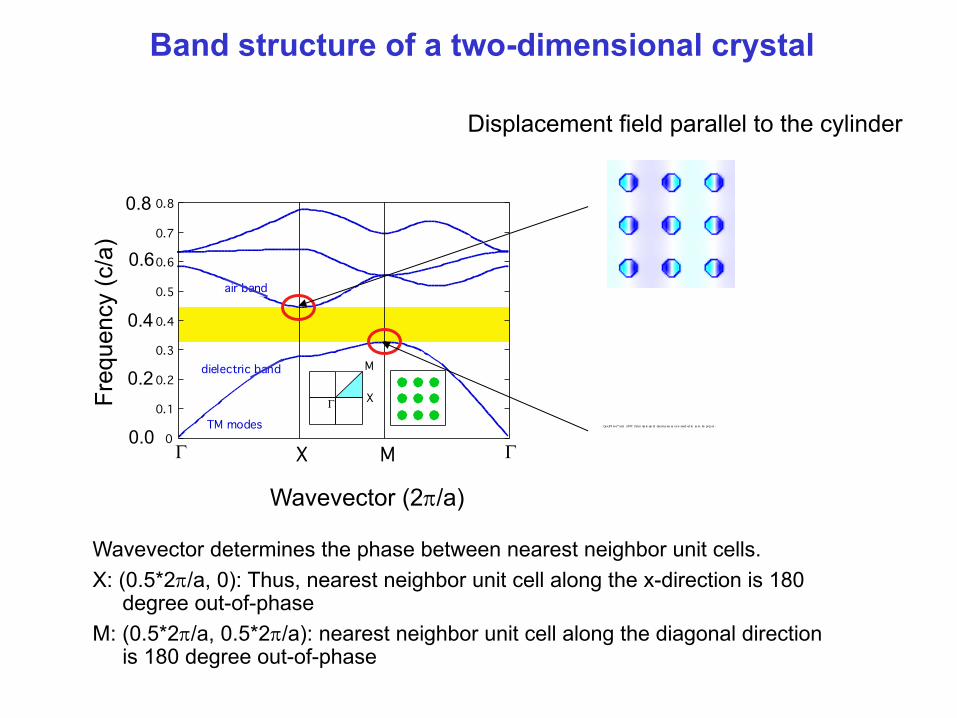
Band structure of a two-dimensional crystal
TM modes
0.8
0.7
0.6
0.5
0.4
0.3
0.2
0.1
0
G X
M
G X M G
dielectric band
air band
Wavevector (2p/a)
Freq
uenc
y (c
/a)
G
0.0
0.2
0.4
0.6
0.8
Displacement field parallel to the cylinder
Wavevector determines the phase between nearest neighbor unit cells.X: (0.5*2p/a, 0): Thus, nearest neighbor unit cell along the x-direction is 180
degree out-of-phaseM: (0.5*2p/a, 0.5*2p/a): nearest neighbor unit cell along the diagonal direction
is 180 degree out-of-phase
Qu ickTi me™ and a TI FF (Unco mp re sse d) decomp res so r are need ed to se e t hi s pi ctu re .

Bragg scattering
Incident light
eikxa
re-ikx
Regardless of how small the reflectivity r is from an individual scatter, the total reflection R from a semi infinite structure:
R = re− ikx + re −2ikae− ikx + re −4 ikae− ikx + ... = re− ikx 11− e−2ika
Diverges if
e2ika = 1 Bragg conditionk = πa
Light can not propagate in a crystal, when the frequency of the incident light is such that the Bragg condition is satisfied
Origin of the photonic band gap

Vacuum: e=1, µ=1, plane-wave solution to the Maxwell’s equation:
A simple example of the band-structure: vacuum (1d)
€
k •H = 0
A band structure, or dispersion relation defines the relation between the frequency w, and the wavevector k.
€
Hei(k ⋅r−ωt )with a transversality constraints:
k
€
ω = c k
For a one-dimensional system, the band structure can be simply depicted as:
k
w=ck
w

Light cone
Visualization of the vacuum band structure (2d)
For a two-dimensional system:
€
ω = c kx2 + ky
2
A few ways to visualize this band structure :
w
kx
ky
This function depicts a cone: light cone.
kx
ky
w
Constant frequency contour Projected band diagram
w
kx0
w=ckx
Light line
Band diagram along several “special”directions
Continuum of plane wave
w
(k,0) (k,k)(0,0) (0,0)k

Maxwell’s equation in the steady state
Time-dependent Maxwell’s equation in dielectric media:
Time harmonic mode (i.e. steady state):
Maxwell equation for the steady state:
€
∇•H r, t( ) = 0
€
∇•εE r, t( ) = 0€
∇×H r, t( ) −ε r( )∂ ε0E r, t( )( )
∂t= 0
€
∇ ×E r,t( ) +∂ µ0H r,t( )( )
∂t= 0
€
H r,t( ) =H r( )e−iωt
€
E r,t( ) = E r( )e−iωt
€
∇ ×E r( ) − iω µ0H r( )( ) = 0
€
∇ ×H r( ) + iω ε r( )ε0E r( )( ) = 0

Master’s equation for steady state in dielectric
Expressing the equation in magnetic field only:
Thus, the Maxwell’s equation for the steady state can be expressed in terms of an eigenvalue problem, in direct analogy to quantum mechanics that governs the properties of electrons.
Quantum mechanics ElectromagnetismField
Eigen-value problem
Operator
€
∇×1
ε r( )∇×H r( ) =
ωc&
' (
)
* + 2
H r( )
€
c =1ε0µ0
€
Ψ r, t( ) =Ψ r( )e jωt
€
H r, t( ) = H r( )eiωt
€
ˆ H Ψ r( ) = EΨ r( )
€
ˆ H = − 2∇2
2m+ V r( )
€
ΘH r( ) =ω 2
c 2$
% &
'
( ) H r( )
€
Θ = ∇×1
ε r( )∇×

Donor and Acceptor States
Dielectric defect
p-state
Air defect
s-stateP. R. Villeneuve, S. Fan, and J. D. Joannopoulos, Phys. Rev. B 54, 7837 (1996)
radius of defect (c/a)0.0 0.1 0.2 0.3 0.4
0.2
0.3
0.4
0.5
frequ
ency
(c/a
)
Air defect Dielectric defect

Line defect states: projected band diagram
0.0
0.1
0.2
0.3
0.4
0.5
0.0 0.1 0.2 0.3 0.4 0.5
Guided Modes
Wavevector (2p/a)
Freq
uenc
y (c
/a)
Electric field
parallel wavevector

Conventional waveguide Photonic crystal waveguide
Photonic crystal vs. conventional waveguide
High-index region Low index region

High transmission through sharp bends
A. Mekis et al, PRL, 77, 3786 (1996)Polluck, Fundamentals of Optoelectronics, 1995

Micro add/drop filter in photonic crystals
S. Fan, P. R. Villeneuve, J. D. Joannopoulos, and H. A. Haus, Physical Review Letters 80, 960 (1998).
• Two resonant modes with even and odd symmetry.• The modes must be degenerate.• The modes must have the same decay rate.

Summary
Qu ickTi me™ and a TI FF (Unco mp re sse d) decomp res so r are need ed to se e t hi s pi ctu re .
Qu ickTi me™ and a TI FF (Unco mp re sse d) decomp res so r are need ed to se e t hi s pi ctu re .
TM modes
0.8
0.7
0.6
0.5
0.4
0.3
0.2
0.1
0
G X
M
G X M G
dielectric band
air band
Wavevector (2p/a)Fr
eque
ncy
(c/a
)
G X M G
G X
M
0.0
0.2
0.4
0.6
0.8
•Photonic crystals are artificial media with a periodic index contrast.
•Electromagnetic wave in a photonic crystal is described by a band structure, which relates the frequency of modes to the wavevectors.
•Fundamental properties of modes: scale invariance, orthogonality