Embed Size (px)
Citation preview

Topic # 08
Structuring System Process Requirements
CIS Life Cycle and Requirements Structuring Stage

1. Data Flow Diagrams
2. Rules and Guidelines to DFD development that lead to accurate and
well-structured process models.
3. DFD decomposition into lower-level diagrams.
4. Balancing higher-level and lower level data flow diagrams.
5. Four main types of DFDs: a) current physical, b) current logical, c) new physical, and d) new logical.
Objectives
Data Flow Diagrams
Data Flow Diagrams
In this class, our focus will be on one tool used to coherently represent the information gathered as part of requirements determination – Data
Flow Diagrams (DFDs). A Data Flow Diagram is a picture of the movement of data between external
entities and the processes and data stores within a system.
Systems analysts use data flow diagrams to help them model the processes internal to an information system and how data from the system’s environment enter the system, are used by the system, and are returned to the environment. DFDs help analysts understand how the organization handles information and what its information needs are or might be. Analysts also use DFDs to study alternative information handling procedures
during the process of designing new information services.

An Example of Data Flow Diagram
Data Flow Diagramming Mechanics
Data Flow Diagramming Mechanics
DFDs are versatile diagramming tools. With only four (4) simple symbols, you can use data DFDs to represent both physical and logical information systems.
There two different standard sets of DFD symbols, but each set consists of four
symbols that represent the same things: data flows, data stores, processes/actions, and sources/sinks (or external entities).
A Data Flow can be best understand as data in motion, moving from one
place in a system to another.
A Data Store is data at rest (files, folders, etc.).
A Data Process is the work or actions performed on data so that they are transformed, stored, and/or distributed.
A Data Source is the origin and/or destination of data, sometimes referred to as external entities.

Comparison of 1) DeMarco & Yourdan,
and 2) Gane & Sarson
DFD Symbol Sets
DFD Rules
1) Processes cannot have only outputs, cannot have only inputs, and must have
a verb phrase label. 2) Data can only move to a data store from a process, not from another data
store or an outside source.
3) Similarly, data can only be moved to an outside sink or to another data store by a process.
4) Data to and from external sources and sinks can only be moved by
processes.
5) Data flows move in one direction only.
6) Both branches of a forked or a joined data flow must represent the same type of data.
7) A data flow cannot return to the process from which it originated.
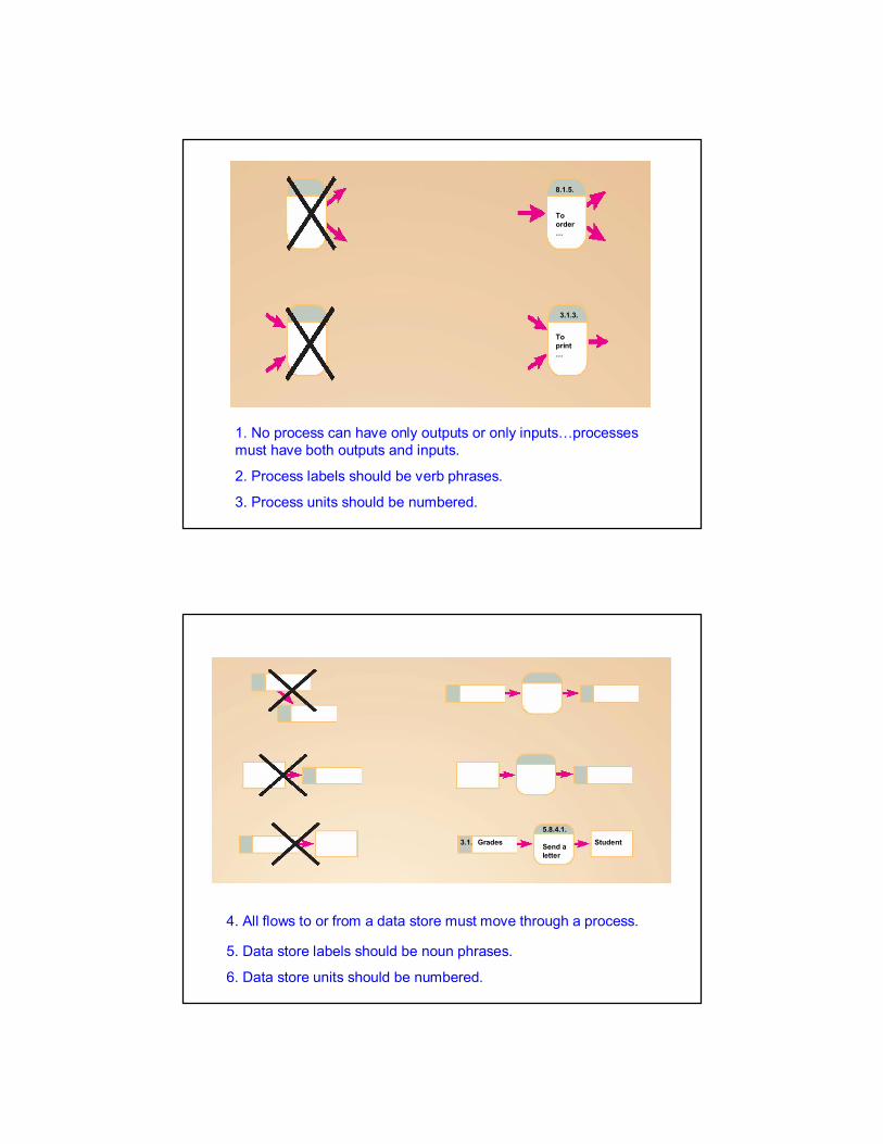
1. No process can have only outputs or only inputs…processes must have both outputs and inputs.
2. Process labels should be verb phrases.
3. Process units should be numbered.
To print …
3.1.3.
8.1.5.
To order …
5. Data store labels should be noun phrases.
4. All flows to or from a data store must move through a process.
6. Data store units should be numbered.
3.1. Grades StudentSend a letter
5.8.4.1.

8. Source and sink labels should be noun phrases.
7. No data moves directly between external entities without going through a process. Interactions between external entities without intervening processes are outside the system and therefore not represented in the DFD.
StudentDean’s Office
Send a letter
5.8.4.1.
9. Bidirectional flow between process and data store is represented by two separate arrows.
10. Forked data flow must refer to exact same data item (not different data items) from a common location to multiple destinations.
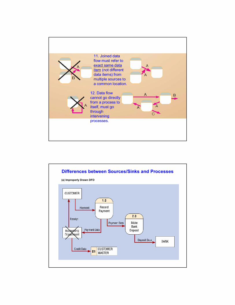
11. Joined data flow must refer to exact same data item (not different data items) from multiple sources to a common location.
12. Data flow cannot go directly from a process to itself, must go through intervening processes.
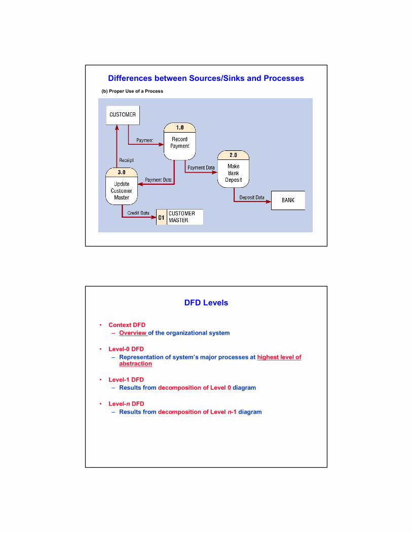
Differences between Sources/Sinks and Processes
(a) Improperly Drawn DFD
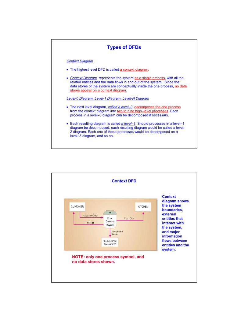
Differences between Sources/Sinks and Processes
(b) Proper Use of a Process
DFD Levels
• Context DFD
– Overview of the organizational system
• Level-0 DFD
– Representation of system’s major processes at highest level of abstraction
• Level-1 DFD
– Results from decomposition of Level 0 diagram
• Level-n DFD
– Results from decomposition of Level n-1 diagram
Types of DFDs
Context Diagram The highest level DFD is called a context diagram. Context Diagram represents the system as a single process, with all the
related entities and the data flows in and out of the system. Since the data stores of the system are conceptually inside the one process, no data stores appear on a context diagram.
Level-0 Diagram, Level-1 Diagram, Level-N Diagram
The next level diagram, called a level–0, decomposes the one process
from the context diagram into two to nine high–level processes. Each process in a level–0 diagram can be decomposed if necessary.
Each resulting diagram is called a level–1. Should processes in a level–1
diagram be decomposed, each resulting diagram would be called a level–2 diagram. Each one of these processes would be decomposed on a level–3 diagram, and so on.
Context diagram shows the system boundaries, external entities that interact with the system, and major information flows between entities and the system.
NOTE: only one process symbol, and no data stores shown.
Context DFD
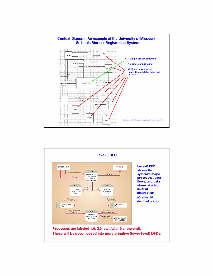
Context Diagram: An example of the University of Missouri –St. Louis Student Registration System
http://www.umsl.edu/~sauterv/analysis/dfd/dfd_homework.html
• A single processing unit
• No data storage units
• Multiple data sources (providers of data, receivers of data)
Level-0 DFD shows the system’s major processes, data flows, and data stores at a high level of abstraction
(O after 1st
decimal point)
Processes are labeled 1.0, 2.0, etc. (with 0 at the end).
These will be decomposed into more primitive (lower-level) DFDs.
Level-0 DFD

Level 0 Diagram: An example of the University of Missouri –St. Louis Student Registration System
http://www.umsl.edu/~sauterv/analysis/dfd/dfd_homework.html
• Main (single) processing unit is divided into sub-units (level-0 processing units)
• Use of data storage units
• Still multiple data sources (providers of data, receivers of data) –they are the same as at Context DFD
Level-1 DFD shows the sub-processes of one of the processes in the Level-0 DFD.
This is a Level-1 DFD for Process 4.0. (1 digit after 1st
decimal point).
Processes are labeled 4.1, 4.2, etc. These can be further decomposed in more primitive (lower-level) DFDs if necessary.
Level-1 DFD

Level-n DFD
Level-n DFD shows the sub-processes of one of the processes in the Level n-1DFD.
This is a Level-2 DFD for Process 4.3. (2 digits after 1st decimal point)
Processes are labeled 4.3.1, 4.3.2, etc. If this is the lowest level of the hierarchy, it is called a primitive DFD.
Multi-Level DFD: Webster-Plus system example
Context DFD
(a fragment)
Level-0 DFD
(a fragment)
Level-1 DFD
(a fragment)
Level-2 DFD
(a fragment)
Main processing unit:
to register for courses
- to add a course
- to pay for a course
…
- to display schedule
…
…
…
- to pay with credit card
- to pay with cache
…
- to pay with transfer of money
- to enter CC number
- to enter FIrstName and LastName
…
- to confirm amount to be paid
1.0 2.0 9.0
2.1 2.2 2.9
2.1.1 2.1.2 2.1.9

Decomposition and Balancing of DFDs
Decomposition of DFDs Decomposition is the iterative process by which a system description is broken down into finer and finer detail, creating a set of diagrams in which one process on a given diagram is explained in greater detail on a lower–level diagram. Balancing is the conservation of inputs and outputs to a data flow diagram process when that process is decomposed to a lower level. You can determine if a set of DFDs are balanced or not by observing whether or not a process which appears in a level–n diagram has the same inputs and outputs when decomposed for a lower-level diagram.
Topic # 08
Structuring System Process Requirements:In-Classroom Exercise
Four Different Types of DFDs
Types of DFDs There are actually four different types of DFDs used in system’s development process:
1) Current physical, 2) Current logical, 3) New logical, and 4) New physical.
Current physical DFDs often show the people and technology used within a system, showing who does what and the media on which data are stored.
Current logical DFDs attempt to show the essence of the system without regard to the actual physical implementation. Note: Detailed DFDs for the current physical system tend to take a great deal of time and then tend to be tossed aside as the focus shifts from the current to the new system. By not drawing current physical DFDs, or by drawing only cursory ones, analysts can save themselves effort and focus from the beginning on what is really important, the new system.
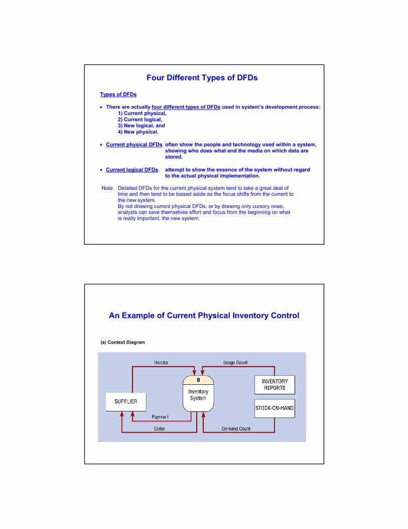
An Example of Current Physical Inventory Control
(a) Context Diagram
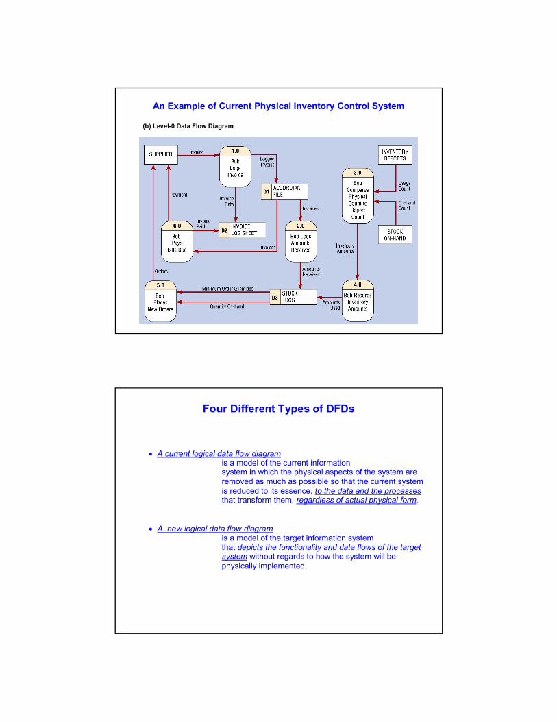
An Example of Current Physical Inventory Control System
(b) Level-0 Data Flow Diagram
Four Different Types of DFDs
A current logical data flow diagram is a model of the current information system in which the physical aspects of the system are removed as much as possible so that the current system is reduced to its essence, to the data and the processes that transform them, regardless of actual physical form. A new logical data flow diagram
is a model of the target information system that depicts the functionality and data flows of the target system without regards to how the system will be physically implemented.

Level-0 Data Flow Diagram for Current Logical Inventory Control System
Level-0 Flow Diagram for New Logical Inventory Control System
Guidelines for Drawing DFDs
Additional DFD Guidelines: DFD Completeness the extent to which all necessary components of a data flow diagram have been included and fully described. DFD Consistency the extent to which information contained on one level of a set of nested DFDs is also included on other levels. Timing Iterative Development
Primitive DFDs the lowest level of decomposition for a DFD.
Topic # 08
Structuring System Process Requirements:Homework Assignment


![STRUCTURING FINANCIAL REQUIREMENTS [IB 2001]](https://img.dokumen.tips/doc/110x75/61bd228561276e740b0fb654/structuring-financial-requirements-ib-2001.jpg)
