Embed Size (px)
Citation preview
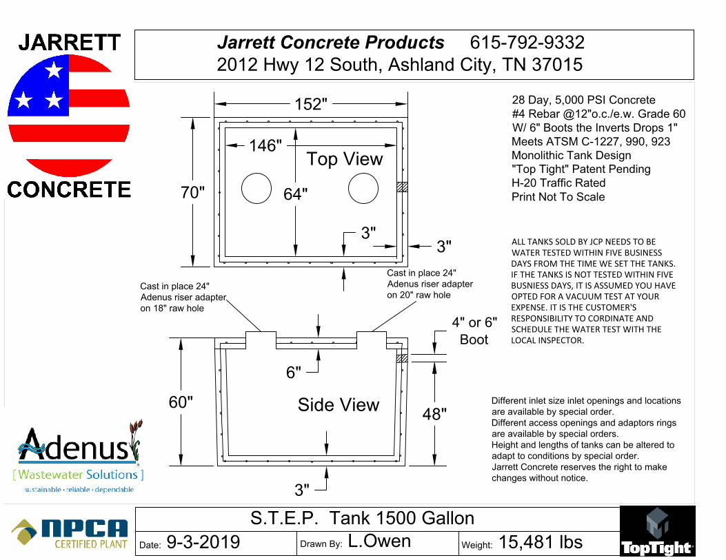
Date: 9-3-2019Drawn By: L.Owen
Weight: 15,481 lbs
Jarrett Concrete Products 615-792-9332
2012 Hwy 12 South, Ashland City, TN 37015
S.T.E.P. Tank 1500 Gallon
Side View
Top View
3"
70"
152"
146"
3"
3"
64"
6"
60"
48"
4" or 6"
Boot
Different inlet size inlet openings and locations
are available by special order.
Different access openings and adaptors rings
are available by special orders.
Height and lengths of tanks can be altered to
adapt to conditions by special order.
Jarrett Concrete reserves the right to make
changes without notice.
ALL TANKS SOLD BY JCP NEEDS TO BEWATER TESTED WITHIN FIVE BUSINESSDAYS FROM THE TIME WE SET THE TANKS.IF THE TANKS IS NOT TESTED WITHIN FIVEBUSNIESS DAYS, IT IS ASSUMED YOU HAVEOPTED FOR A VACUUM TEST AT YOUREXPENSE. IT IS THE CUSTOMER'SRESPONSIBILITY TO CORDINATE ANDSCHEDULE THE WATER TEST WITH THELOCAL INSPECTOR.
28 Day, 5,000 PSI Concrete
#4 Rebar @12"o.c./e.w. Grade 60
W/ 6" Boots the Inverts Drops 1"
Meets ATSM C-1227, 990, 923
Monolithic Tank Design
"Top Tight" Patent Pending
H-20 Traffic Rated
Print Not To Scale
Cast in place 24"
Adenus riser adapter
on 18" raw hole
Cast in place 24"
Adenus riser adapter
on 20" raw hole

STA-RITE® JP Series Signature 2000® composite 4" submersible pumps
Precision-engineered, corrosion-resistant Signature 2000® Composite Pumps in 10, 15, 20 and 30 GPM deliver efficient, dependable performance even in rough, aggressive water. Heads to over 650 feet and capacities to 45 GPM. Built to deliver long-term, trouble-free service.
These pumps feature the proven SignaSeal™ staging system. Floating impeller design resists sand and reduces sand locking.
APPliCATionSWater systems…for residential, industrial, commercial, multiple housing and farm use.
SPECiFiCATionSShell: Stainless steelDiameter: 3-7/8"Discharge: Fiberglass-reinforced thermoplasticDischarge Bearing: Nylatron®
intermediate Bearing: (On larger units) polycarbonate, nitrile rubber and stainless steelimpellers: AcetalDiffusers: PolycarbonateSuction Caps: Polycarbonate with stainless steel insertThrust Pads: Proprietary spec.Shaft and Coupling: Stainless steelintake: Fiberglass-reinforced thermoplasticintake Screen: PolypropyleneCable Guard: Stainless steelCheck Valve: AcetalAgency listings: CSA
Nylatron® is a registered trademark of Polymer Corp. All other brand or product names are trademarks or registered trademarks of Pentair Ltd.
FEATurESProven Staging System: Our proven SignaSeal staging system incorporates a harder-than-sand ceramic wear surface that when incorporated with our floating impeller design, greatly reduces problems with abrasives, sand lock-up and running dry.Discharge: Corrosion-resistant fiberglass-reinforced thermoplastic for durability in aggressive water. Large octagon wrench area for ease of installation.Discharge Bearing: Exclusive self-lubricating Nylatron bearing resists wear from sand.intake: Corrosion-resistant fiberglass-reinforced thermoplastic for durability in aggressive water.Shaft: Positive drive from 7/16" hexagonal heavy-duty 300 grade stainless steel.Coupling: Stainless steel press fit to pump shaft. Couples to all standard NEMA motors.Shell: Heavy-walled corrosion-resistant stainless steel. Threaded for easy servicing.Hardware: All screws, washers and nuts are corrosion-resistant 300 grade stainless steel.Check Valve: Durable internal poppet-type check valve.Cable Guard: Corrosion-resistant stainless steel guard protects motor leads. Tapered ends prevent pump from catching on well.intake Screen: Corrosion-proof polypropylene. Pentek® XE Series™ Motor: 2 and 3 wire NEMA standard all stainless construction water-filled motors.
1 S4559wS

STA-RITE® JP Series Signature 2000® composite 4" submersible pumps
* Length and weight are approximate.**For 10 GPM, 15 GPM, 20 GPM and 30 GPM discharge is 1-1/4" NPT.NOTE: On 2 HP and larger pumps – Motor, Control Box or Magnetic Starter must be ordered separately.
orDErinG inForMATion
GPMMoTor TyPE HP STGS. PH VolT
ASSEMBlED PuMP PuMP EnD MoTor ConTrol BoXCATAloG nuMBEr
lEnGTHinCHES*
WEiGHTPounDS*
CATAloG nuMBEr
lEnGTHinCHES*
WEiGHTPounDS*
CATAloG nuMBEr
WEiGHTPounDS*
CATAloG nuMBEr
WEiGHTPounDS*
10**
2 WirE
1/2 7 1 115 S10P4JP05121 22-3/4 27-1/2 L10P4CJ 12-3/4 9 P42B0005A1 191/2 7 1 230 S10P4JP05221 22-3/4 27-1/2 L10P4CJ 12-3/4 9 P42B0005A2 193/4 10 1 230 S10P4JP07221 25-3/4 30-1/2 L10P4DJ 14-1/2 10 P42B0007A2 231 13 1 230 S10P4JP10221 28-3/4 34-1/2 L10P4EJ 16 10-3/4 P42B0010A2 25
1-1/2 17 1 230 S10P4JP15221 34-3/4 41-1/2 L10P4FJ 19-3/4 12-1/2 P42B0015A2 29
3 WirE
1/2 7 1 115 S10P4JP05131 22-3/4 27-1/2 L10P4CJ 12-3/4 9 P43B0005A1 19 SMC-IR0511 41/2 7 1 230 S10P4JP05231 22-3/4 27-1/2 L10P4CJ 12-3/4 9 P43B0005A2 18 SMC-CR0521 43/4 10 1 230 S10P4JP07231 25-3/4 30-1/2 L10P4DJ 14-1/2 10 P43B0007A2 21 SMC-CR0721 41 13 1 230 S10P4JP10231 28-3/4 34-1/2 L10P4EJ 16-1/4 10-3/4 P43B0010A2 23 SMC-CR1021 41 13 3 230 L10P4EJ 15-1/2 10-1/4 P43B0010A3 231 13 3 460 L10P4EJ 15-1/2 10-1/4 P43B0010A4 23
1-1/2 17 1 230 S10P4JP15231 33-1/2 41-1/2 L10P4FJ 19-3/4 12-1/2 P43B0015A2 27 SMC-CR1521 71-1/2 17 3 230 L10P4FJ 19-3/4 12-1/2 P43B0015A3 231-1/2 17 3 460 L10P4FJ 19-3/4 12-1/2 P43B0015A4 23
15**
2 WirE
1/2 5 1 115 S15P4JP05121 22-1/4 27 L15P4CJ 12-1/4 9 P42B0005A1 191/2 5 1 230 S15P4JP05221 22-1/4 27 L15P4CJ 12-1/4 9 P42B0005A2 193/4 7 1 230 S15P4JP07221 25-3/4 31 L15P4DJ 14-1/2 10 P42B0007A2 231 9 1 230 S15P4JP10221 29-1/4 35 L15P4EJ 16-3/4 11 P42B0010A2 25
1-1/2 12 1 230 S15P4JP15221 35-1/4 43 L15P4FJ 20-1/4 13 P42B0015A2 29
3 WirE
1/2 5 1 115 S15P4JP05131 22-1/4 27 L15P4CJ 12-1/4 9 P43B0005A1 19 SMC-IR0511 41/2 5 1 230 S15P4JP05231 22-1/4 27 L15P4CJ 12-1/4 9 P43B0005A2 18 SMC-CR0521 43/4 7 1 230 S15P4JP07231 25-3/4 31 L15P4DJ 14-1/2 10 P43B0007A2 21 SMC-CR0721 41 9 1 230 S15P4JP10231 29-1/4 35 L15P4EJ 16-3/4 11 P43B0010A2 23 SMC-CR1021 41 9 3 230 L15P4EJ 15-1/2 10-1/4 P43B0010A3 231 9 3 460 L15P4EJ 15-1/2 10-1/4 P43B0010A4 23
1-1/2 12 1 230 S15P4JP15231 33-3/4 41 L15P4FJ 20-1/4 13 P43B0015A2 27 SMC-CR1521 71-1/2 12 3 230 L15P4FJ 20-1/4 13 P43B0015A3 231-1/2 12 3 460 L15P4FJ 20-1/4 13 P43B0015A4 23
20**
2 WirE3/4 5 1 230 S20P4JP07221 23-3/4 30 L20P4DJ 12-1/2 8-1/2 P42B0007A2 231 7 1 230 S20P4JP10221 27-1/4 34 L20P4EJ 14-3/4 9-3/4 P42B0010A2 25
1-1/2 9 1 230 S20P4JP15221 32 39 L20P4FJ 16-3/4 10-3/4 P42B0015A2 29
3 WirE
3/4 5 1 230 S20P4JP07231 23-3/4 30 L20P4DJ 12-1/2 8-1/2 P43B0007A2 21 SMC-CR0721 41 7 1 230 S20P4JP10231 27-1/4 34 L20P4EJ 14-3/4 9-3/4 P43B0010A2 23 SMC-CR1021 41 7 3 230 L20P4EJ 15-1/2 10-1/4 P43B0010A3 231 7 3 460 L20P4EJ 15-1/2 10-1/4 P43B0010A4 23
1-1/2 9 1 230 S20P4JP15231 30-1/2 39 L20P4FJ 16-3/4 10-3/4 P43B0015A2 27 SMC-CR1521 71-1/2 9 3 230 L20P4FJ 16-3/4 10-3/4 P43B0015A3 231-1/2 9 3 460 L20P4FJ 16-3/4 10-3/4 P43B0015A4 23
2 12 1 230 L20P4GJ 20-1/4 12-1/2 P43B0020A2 31 SMC-CR2021 72 12 3 230 L20P4GJ 20-1/4 12-1/2 P43B0020A3 232 12 3 460 L20P4GJ 20-1/4 12-1/2 P43B0020A4 23
30**
2 WirE 1 5 1 230 S30P4JP10221 26-1/2 35 L30P4EJ 14 10 P42B0010A2 251-1/2 6 1 230 S30P4JP15221 30-1/2 39 L30P4FJ 15-1/4 11 P42B0015A2 29
3 WirE
1 5 1 230 S30P4JP10231 26-1/2 35 L30P4EJ 14 10 P43B0010A2 23 SMC-CR1021 41 5 3 230 L30P4EJ 15-1/2 10-1/4 P43B0010A3 231 5 3 460 L30P4EJ 15-1/2 10-1/4 P43B0010A4 23
1-1/2 6 1 230 S30P4JP15231 29 39 L30P4FJ 15-1/4 11 P43B0015A2 27 SMC-CR1521 71-1/2 6 3 230 L30P4FJ 15-1/4 11 P43B0015A3 231-1/2 6 3 460 L30P4FJ 15-1/4 11 P43B0015A4 23
2 8 1 230 L30P4GJ 18-1/4 12 P43B0020A2 31 SMC-CR2021 72 8 3 230 L30P4GJ 18-1/4 12 P43B0020A3 232 8 3 460 L30P4GJ 18-1/4 12 P43B0020A4 23
2 S4559wS
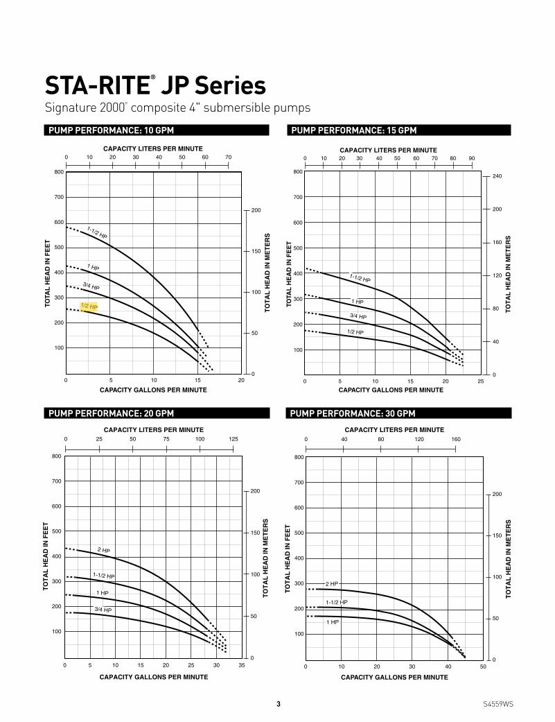
STA-RITE® JP Series Signature 2000® composite 4" submersible pumpsPuMP PErForMAnCE: 10 GPM
0 5
800
700
600
500
400
300
200
100
10 15 20
200
150
100
50
0
TOTA
L H
EA
D IN
FE
ET
CAPACITY GALLONS PER MINUTE
CAPACITY LITERS PER MINUTE
TO
TA
L H
EA
D IN
ME
TE
RS
10 70605040200 30
1-1/2 HP
1 HP
3/4 HP
1/2 HP
PuMP PErForMAnCE: 15 GPM
800
700
600
500
400
300
200
100
0 5 10 15 20 25
240
200
160
120
80
40
0
TOTA
L H
EA
D IN
FE
ET
CAPACITY GALLONS PER MINUTE
CAPACITY LITERS PER MINUTE
TO
TA
L H
EA
D IN
ME
TE
RS
30 908070604020100 50
1-1/2 HP
1 HP
3/4 HP
1/2 HP
PuMP PErForMAnCE: 30 GPM
0 10 50
800
700
600
500
400
300
200
100
CAPACITY GALLONS PER MINUTE
TO
TA
L H
EA
D IN
FE
ET
20 30 40
2 HP
1-1/2 HP
1 HP
CAPACITY LITERS PER MINUTE
TO
TA
L H
EA
D IN
ME
TE
RS
16080400 120
200
150
100
50
0
PuMP PErForMAnCE: 20 GPM
CAPACITY GALLONS PER MINUTE
TO
TA
L H
EA
D IN
FE
ET
0 5 10 20 25 3015 35
800
700
600
500
400
300
200
100
CAPACITY LITERS PER MINUTE
TO
TA
L H
EA
D IN
ME
TE
RS
75 12550250 100
200
150
100
50
0
1-1/2 HP
1 HP
3/4 HP
2 HP
3 S4559wS
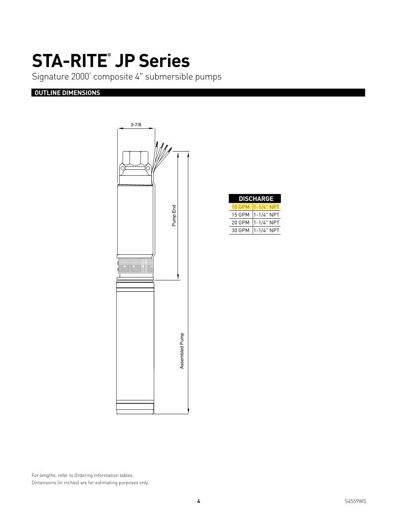
STA-RITE® JP Series Signature 2000® composite 4" submersible pumpsouTlinE DiMEnSionS
3-7/8
Pum
p E
nd
Ass
embl
ed P
ump
For lengths, refer to Ordering Information tables. Dimensions (in inches) are for estimating purposes only.
DiSCHArGE10 GPM 1-1/4" NPT15 GPM 1-1/4" NPT20 GPM 1-1/4" NPT30 GPM 1-1/4" NPT
4 S4559wS
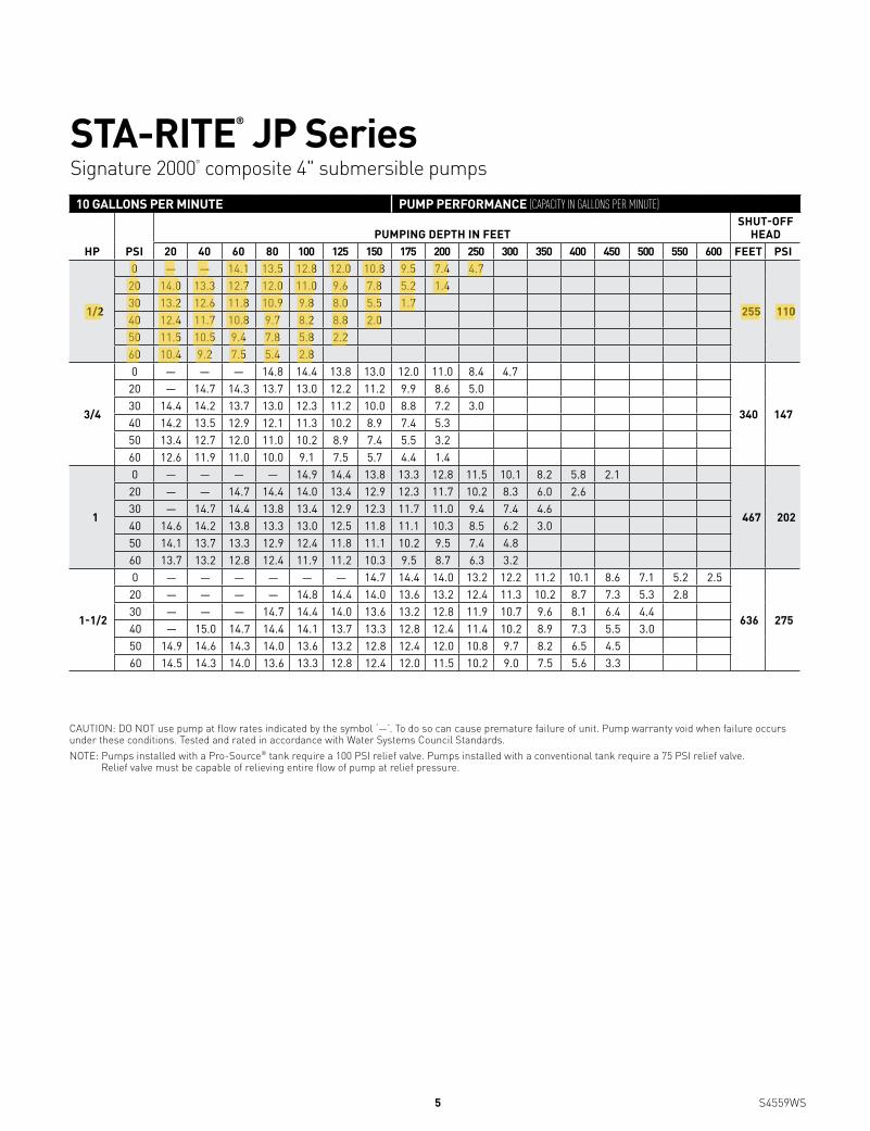
STA-RITE® JP Series Signature 2000® composite 4" submersible pumps
CAUTION: DO NOT use pump at flow rates indicated by the symbol ‘—’. To do so can cause premature failure of unit. Pump warranty void when failure occurs under these conditions. Tested and rated in accordance with water Systems Council Standards.NOTE: Pumps installed with a Pro-Source® tank require a 100 PSI relief valve. Pumps installed with a conventional tank require a 75 PSI relief valve.
Relief valve must be capable of relieving entire flow of pump at relief pressure.
10 GAllonS PEr MinuTE PuMP PErForMAnCE (CapaCity in Gallons per Minute)
HP PSiPuMPinG DEPTH in FEET
SHuT-oFF HEAD
20 40 60 80 100 125 150 175 200 250 300 350 400 450 500 550 600 FEET PSi
1/2
0 — — 14.1 13.5 12.8 12.0 10.8 9.5 7.4 4.7
255 110
20 14.0 13.3 12.7 12.0 11.0 9.6 7.8 5.2 1.430 13.2 12.6 11.8 10.9 9.8 8.0 5.5 1.740 12.4 11.7 10.8 9.7 8.2 8.8 2.050 11.5 10.5 9.4 7.8 5.8 2.260 10.4 9.2 7.5 5.4 2.8
3/4
0 — — — 14.8 14.4 13.8 13.0 12.0 11.0 8.4 4.7
340 147
20 — 14.7 14.3 13.7 13.0 12.2 11.2 9.9 8.6 5.030 14.4 14.2 13.7 13.0 12.3 11.2 10.0 8.8 7.2 3.040 14.2 13.5 12.9 12.1 11.3 10.2 8.9 7.4 5.350 13.4 12.7 12.0 11.0 10.2 8.9 7.4 5.5 3.260 12.6 11.9 11.0 10.0 9.1 7.5 5.7 4.4 1.4
1
0 — — — — 14.9 14.4 13.8 13.3 12.8 11.5 10.1 8.2 5.8 2.1
467 202
20 — — 14.7 14.4 14.0 13.4 12.9 12.3 11.7 10.2 8.3 6.0 2.630 — 14.7 14.4 13.8 13.4 12.9 12.3 11.7 11.0 9.4 7.4 4.640 14.6 14.2 13.8 13.3 13.0 12.5 11.8 11.1 10.3 8.5 6.2 3.050 14.1 13.7 13.3 12.9 12.4 11.8 11.1 10.2 9.5 7.4 4.860 13.7 13.2 12.8 12.4 11.9 11.2 10.3 9.5 8.7 6.3 3.2
1-1/2
0 — — — — — — 14.7 14.4 14.0 13.2 12.2 11.2 10.1 8.6 7.1 5.2 2.5
636 275
20 — — — — 14.8 14.4 14.0 13.6 13.2 12.4 11.3 10.2 8.7 7.3 5.3 2.830 — — — 14.7 14.4 14.0 13.6 13.2 12.8 11.9 10.7 9.6 8.1 6.4 4.440 — 15.0 14.7 14.4 14.1 13.7 13.3 12.8 12.4 11.4 10.2 8.9 7.3 5.5 3.050 14.9 14.6 14.3 14.0 13.6 13.2 12.8 12.4 12.0 10.8 9.7 8.2 6.5 4.560 14.5 14.3 14.0 13.6 13.3 12.8 12.4 12.0 11.5 10.2 9.0 7.5 5.6 3.3
5 S4559wS

STA-RITE® JP Series Signature 2000® composite 4" submersible pumps
CAUTION: DO NOT use pump at flow rates indicated by the symbol ‘—’. To do so can cause premature failure of unit. Pump warranty void when failure occurs under these conditions.Tested and rated in accordance with water Systems Council Standards.NOTE: Pumps installed with a Pro-Source® tank require a 100 PSI relief valve. Pumps installed with a conventional tank require a 75 PSI relief valve.
Relief valve must be capable of relieving entire flow of pump at relief pressure.
15 GAllonS PEr MinuTE PuMP PErForMAnCE (CapaCity in Gallons per Minute)
HP PSiPuMPinG DEPTH in FEET
SHuT-oFF HEAD
20 40 60 80 100 125 150 175 200 250 300 350 400 450 500 FEET PSi
1/2
0 — 21.5 20.0 18.7 16.9 13.1 7.4
175 76
20 19.7 18.3 16.3 13.0 8.830 18.0 15.6 12.4 7.9 2.040 15.2 11.9 7.050 11.2 5.860 4.8
3/4
0 — — 21.2 20.2 19.3 17.8 16.0 13.2 9.6
245 106
20 20.9 19.9 19.0 17.7 16.4 13.7 10.0 4.930 19.8 18.8 17.6 16.1 14.0 10.7 5.540 18.6 17.5 15.9 13.5 10.9 6.050 17.2 15.4 13.1 10.0 6.460 15.0 12.7 9.7 5.5 1.8
1
0 — — — — 20.4 19.4 18.4 17.2 15.5 10.3 2.7
318 138
20 — 20.9 20.2 19.3 18.7 17.5 15.8 13.4 10.9 3.230 20.8 20.0 19.1 18.5 17.6 16.0 13.7 11.1 7.540 19.8 19.0 18.3 17.4 16.2 13.9 11.3 8.1 3.750 18.9 18.2 17.1 15.8 14.0 11.4 8.2 4.060 18.0 17.0 15.6 13.7 11.7 8.4 4.4
1-1/2
0 — — — — — 20.5 19.9 19.3 18.4 16.4 13.1 8.3 2.8
420 182
20 — — 21.2 20.5 20.0 19.3 18.6 17.6 16.5 13.5 9.1 3.230 — 21.1 20.3 19.9 19.3 18.7 17.7 16.6 15.4 11.7 6.340 21.0 20.2 19.8 19.2 18.7 17.9 16.7 15.5 13.7 9.4 3.650 20.2 19.7 19.2 18.6 18.0 16.8 15.6 13.8 11.9 6.760 19.6 19.0 18.5 17.7 16.9 15.7 13.9 12.0 9.7 3.8
6 S4559wS

STA-RITE® JP Series Signature 2000® composite 4" submersible pumps
CAUTION: DO NOT use pump at flow rates indicated by the symbol ‘—’. To do so can cause premature failure of unit. Pump warranty void when failure occurs under these conditions. Tested and rated in accordance with water Systems Council Standards.NOTE: Pumps installed with a Pro-Source® tank require a 100 PSI relief valve. Pumps installed with a conventional tank require a 75 PSI relief valve.
Relief valve must be capable of relieving entire flow of pump at relief pressure.
20 GAllonS PEr MinuTE PuMP PErForMAnCE (CapaCity in Gallons per Minute)
HP PSiPuMPinG DEPTH in FEET
SHuT-oFF HEAD
20 40 60 80 100 125 150 175 200 250 300 350 400 450 FEET PSi
3/4
0 — — — 26.9 23.5 19.0 13.7
180 78
20 — 25.8 22.5 18.5 14.5 3.430 25.2 22.0 18.3 13.9 4.540 21.3 17.6 13.0 3.050 17.2 11.460 10.2
1
0 — — — — — 25.3 22.4 18.8 15.5
251 109
20 — — — 25.1 22.8 19.5 16.1 10.130 — — 24.9 22.5 19.8 16.5 10.640 27.0 24.5 22.0 19.4 16.8 11.6 2.650 24.2 21.5 19.0 16.3 12.5 3.360 21.3 18.6 16.0 11.1 3.7
1-1/2
0 — — — — — — 26.4 24.0 21.6 16.4 5.4
323 140
20 — — — — 26.8 24.4 22.0 19.5 16.8 6.830 — — — 26.5 24.7 22.2 19.6 17.1 13.940 — — 26.2 24.3 22.3 19.8 17.3 14.2 8.050 — 26.0 24.1 22.1 20.0 17.5 14.5 8.360 25.6 23.9 21.9 19.8 17.5 14.8 9.1
2
0 — — — — — — — 27.3 26.0 23.2 20.2 16.2 8.5
435 188
20 — — — — — — 26.1 24.9 23.4 20.6 16.7 9.530 — — — — — 26.2 25.0 23.5 22.1 19.1 13.8 4.840 — — — — 26.4 25.1 23.7 22.2 20.8 17.2 10.150 — — 27.2 26.1 25.1 23.8 22.3 20.9 19.3 14.0 5.760 — 27.1 26.0 25.0 23.9 22.4 21.0 19.4 17.3 10.8
7 S4559wS

STA-RITE® JP Series Signature 2000® composite 4" submersible pumps
293 WRIGHT STREET, DELAVAN, WI 53115 WWW.STA-RITE.COM PH: 888-782-7483 ORDERS FAX: 800-426-9446Because we are continuously improving our products and services, Pentair reserves the right to change specifications without prior notice.
CAUTION: DO NOT use pump at flow rates indicated by the symbol ‘—’. To do so can cause premature failure of unit. Pump warranty void when failure occurs under these conditions. Tested and rated in accordance with water Systems Council Standards.NOTE: Pumps installed with a Pro-Source® tank require a 100 PSI relief valve. Pumps installed with a conventional tank require a 75 PSI relief valve.
Relief valve must be capable of relieving entire flow of pump at relief pressure.
30 GAllonS PEr MinuTE PuMP PErForMAnCE (CapaCity in Gallons per Minute)
HP PSiPuMPinG DEPTH in FEET
SHuT-oFF HEAD
20 40 60 80 100 125 150 175 200 250 300 350 400 450 FEET PSi
1
0 — — 40.9 39.1 36.8 32.5 26.0 8.0
175 76
20 40.4 38.8 36.0 32.4 27.7 13.330 38.0 35.3 31.7 26.3 14.340 35.0 31.4 25.9 12.150 30.2 24.0 3.060 21.9
1-1/2
0 — — 41.9 39.9 37.5 34.1 30.9 26.9 17.0
210 91
20 41.2 39.1 36.5 34.0 31.5 27.8 21.530 38.9 36.1 33.8 31.0 27.9 21.840 36.0 33.5 30.8 27.7 20.250 32.9 30.1 26.8 21.560 29.5 25.9 18.1
2
0 — — — 41.8 40.5 38.8 36.8 34.7 31.6 23.7
280 121
20 — 41.3 40.1 38.7 37.1 34.9 32.1 29.0 24.830 41.2 40.0 38.5 37.0 35.0 32.2 29.1 24.9 15.240 39.9 38.3 36.6 34.8 32.7 29.8 25.1 16.150 38.0 36.3 34.5 32.1 30.0 25.3 17.560 36.0 34.0 31.9 29.1 26.0 18.0
S4559wS (05/20/13)
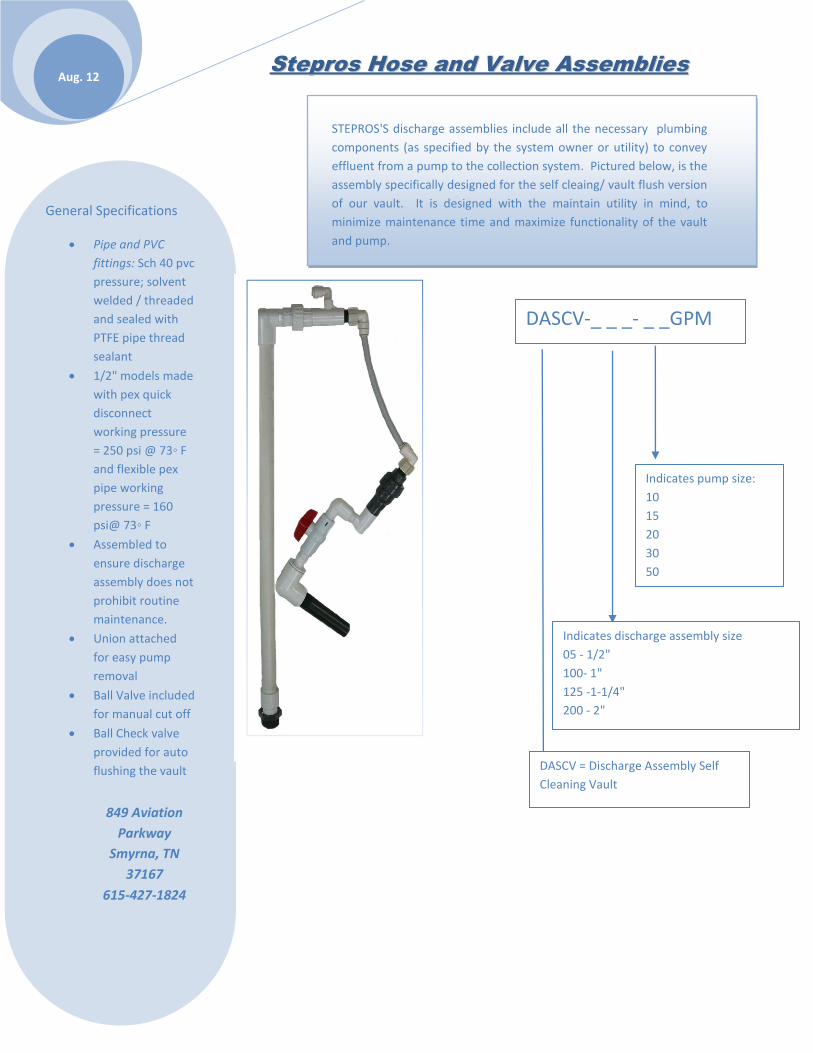
Aug. 12 SStteepprrooss HHoossee aanndd VVaallvvee AAsssseemmbblliieess
DASCV-_ _ _- _ _GPM
General Specifications
• Pipe and PVC
fittings: Sch 40 pvc
pressure; solvent
welded / threaded
and sealed with
PTFE pipe thread
sealant
• 1/2" models made
with pex quick
disconnect
working pressure
= 250 psi @ 73◦ F
and flexible pex
pipe working
pressure = 160
psi@ 73◦ F
• Assembled to
ensure discharge
assembly does not
prohibit routine
maintenance.
• Union attached
for easy pump
removal
• Ball Valve included
for manual cut off
• Ball Check valve
provided for auto
flushing the vault
849 Aviation
Parkway
Smyrna, TN
37167
615-427-1824
STEPROS'S discharge assemblies include all the necessary plumbing
components (as specified by the system owner or utility) to convey
effluent from a pump to the collection system. Pictured below, is the
assembly specifically designed for the self cleaing/ vault flush version
of our vault. It is designed with the maintain utility in mind, to
minimize maintenance time and maximize functionality of the vault
and pump.
DASCV = Discharge Assembly Self
Cleaning Vault
Indicates discharge assembly size
05 - 1/2"
100- 1"
125 -1-1/4"
200 - 2"
Indicates pump size:
10
15
20
30
50
DASCV-05-10GPM

MUNICIPAL OPEN PROFILE SEWER PIPE & FITTINGS
PVC Gravity Flow Systems manufactured to CSA
and ASTM standards
IPEX Ultra-RibTM Pipe and Fittings
(200 mm – 600 mm) (8" – 24" )
CSA B182.4 and ASTM F794
IPEX Ultra-Rib™ is a gravity flow PVC sewerpipe with concentric reinforcing ribs thatencircle the pipe to provide superior ringstiffness and performance. It is an extruded,seamless pipe made from high grade PVC
compound.
Ultra-Rib is available in standard sewer sizes from200mm to 600 mm (8” – 24”). Its optimized profile
design offers strength and reliability, as well aseconomy and superior flow rates.
Features and Benefits
Ultra-Rib offers many advantages over traditional materials, as well asother plastic sewer pipes. Some of these advantages include:
Tight Joints & Lower Treatment Costs: Eliminate infiltration and exfiltration. Ultra-Rib’s50 psi capable joints easily outperform concrete and corrugated PE joints.
Superior Flow Characteristics: Because of the smooth inside wall of Ultra-Rib, aManning’s coefficient of 0.009 can be used when designing systems using Ultra-Ribpipe. This compares with Manning’s coefficients of up to 0.023 for other materialslike clay or concrete.
Abrasion Resistance: Ultra-Rib has been proven to be more abrasion resistant thanother profile pipes, and has out-performed concrete pipe in testing at California StateUniversity.
Chemical Resistance: PVC is virtually immune to chemical attack from any type ofsewage. Hydrogen Sulphide attack, which causes millions of dollars of damage toconcrete and metal infrastructure, will not affect Ultra-Rib.
Stress Crack Resistance: While some HDPE pipes have been found to crackprematurely under load, Ultra-Rib’s tough PVC construction and superior formulationhas been proven to be immune to these problems.
IPEX PVC Profile Pipe - Ultra-RibTM
TOLL FREE U.S.: (800) 463-9572 TOLL FREE CANADA: (866) 473-9462
www.ipexinc.com

© 2004 IPEXPIMNURIP040415
Pipe SizeAverage I.D.
dAverage Diameter
Over Ribs DO.D. at Bell
D3Waterway Wall
t
mm in mm in mm in mm in mm in
200 8 200 7.89 224 8.80 248 9.78 2.20 0.087
250 10 251 9.86 280 11.00 311 12.22 2.30 0.091
300 12 298 11.74 333 13.10 371 14.59 2.60 0.102
375 15 365 14.37 408 16.04 453 17.82 2.80 0.110
450 18 448 17.65 497 19.57 553 21.77 3.30 0.130
525 21 527 20.75 579 22.80 638 25.14 4.06 0.160
600 24 597 23.50 650 25.61 717 28.24 4.58 0.180
TOLL FREE U.S.: (800) 463-9572 TOLL FREE CANADA: (866) 473-9462
www.ipexinc.com
ASTM Embedment
Material Classification
ManufacturedGranularAngular
Clean Sand& Gravel
Sand & Gravelwith Fines Silt & Clay
DENSITY (PROCTOR)AASHO T-99
E'kPa (psi)
Height of Cover m ft1
2
3
4
5
6
7
8
9
10
15
3.3
6.6
9.8
13.1
16.4
19.7
23.0
26.3
29.5
32.8
49.2
0.5
0.5
0.6
0.8
1.1
1.3
1.5
1.7
1.9
2.1
3.2
0.3
0.4
0.4
0.6
0.7
0.9
1.0
1.2
1.3
1.4
2.2
1.0
1.0
1.2
1.6
2.0
2.4
2.8
3.2
3.6
4.0
6.0
90% 85%90% 80%
20 700(3,000)
13 800(2,000)
7 000(1,000)
7 000(1,000)
3 500(500)
2 760(400)
CLASS I CLASS II CLASS III
1.0
1.0
1.2
1.6
2.0
2.4
2.8
3.2
3.6
4.0
6.0
2.1
2.2
2.6
3.5
4.4
5.3
6.1
7.0
7.9
8.8
13.1
1.7
1.8
2.2
2.9
3.7
4.4
5.1
5.9
6.6
7.3
11.0
90% 85%
CLASS IV
Percent (%) Deflection of ULTRA-RIB pipe
Dimensions
Not recommended
ASSEMBLY
AVERAGEDIAMETEROVER RIBS
I.D.t
O.D. BELL (D3)

Aug. 17 SStteepprrooss MMaaxxiimmuumm FFiilltteerr
Technical Specifications
Polypropylene
Schedule 40 PVC
1/8" solids or
smaller
15.3 ft² effective
screen area
Features
Unique inside to
compliment
surface area
with ease of
cleaning and
removal of
buildup.
Superior pump
protection
Maximum
surface area to
ensure delivery
of water to the
pump
849 Aviation Parkway Smyrna,
TN 37167
615-427-1824
STEPROS'S maximum filter series is designed to meet your filtration
requirements. Our filter is unique in design to benefit your
preventative maintenance program Our maximum filter used in
conjunction with our Self Cleaning Vault repels solids back into the
tank instead of collecting them thus providing longer periods of time
between cleaning and increase in pump life.
MF 12
Underside/Inside View

Information Technology Solutions Control/Pump Duty Float Switches
www.ezonsite.com
NNoorrmmaallllyy OOppeenn ((NN//OO)):: Pump duty. As the float raises 1” (5º) above horizontal, the contact becomes closed and completes the circuit. This float is generally used to turn on pumps.
Normally Closed (N/C): Control duty. As the float falls 1” (5º) below horizontal, the contact becomes closed and completes the circuit. This float is generally used to turn off pumps as a fail-safe method (redundant off).
Narrow Angle Floats (N/0): Control duty. As the float raises 1” (10º) above horizontal, the contact becomes closed and completes the circuit. This float is generally used to turn on pumps. With a narrow-angle activated actuation, these are often used in pump stations and recirculating sand filters (RSFs) where water levels require more precision.
Applications For use with EZ-
Onsite control Panels
Pump Stations
Recirculation Sand
Filter Beds.
STEP and STEG tanks
These floats are constructed of a
durable polypropylene outer shell and a solid polyurethane foam interior. They are designed for accurate liquid level control in many applications including sewage and wastewater environments. Float switches can be utilized to signify specific water levels for direct alarm actuation, and can be used as a “pump-on” or “pump off” switch.
SPECIFICATIONS 2.90 x 3.75”
Min/max
temperatures 32-
170ºF
power cord is chlorinated polyethylene type SJOOW- 300v
16/2 for N/O or
18/2 for N/C and wide angle switches.
16/2 N/O 13amps @120-240 VAC ½ H.P
18/2 N/C and Narrow angle N/O 10 AMPS @ 120 VAC, 3 AMPS @ 240 VAC.
FEATURES Leak proof, shock
proof, and impact
resistant
Durable
polypropylene outer
shell and a solid
polyurethane foam
interior
849 Aviation Parkway
Smyrna, TN 37167
615-604-4007
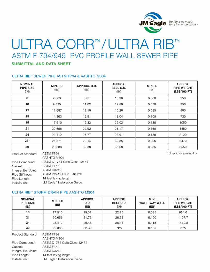
ULTRA RIB™ SEWER PIPE ASTM F794 & AASHTO M304
NOMINAL PIPE SIZE
(IN)
MIN. I.D(IN)
APPROX. O.D.(IN)
APPROX.BELL O.D.
(IN)
MIN. T. (IN)
APPROX.PIPE WEIGHT(LBS/100 FT)
8 7.863 8.81 10.20 0.060 250
10 9.825 11.02 12.80 0.070 350
12 11.687 13.10 15.26 0.085 490
15 14.303 15.91 18.04 0.105 730
18 17.510 19.32 22.02 0.130 1050
21 20.656 22.92 26.17 0.160 1450
24 23.412 25.77 28.91 0.180 2120
27* 26.371 29.14 32.85 0.205 2470
30 29.388 32.38 36.68 0.235 3550
ULTRA RIB™ STORM DRAIN PIPE AASHTO M304
NOMINAL PIPE SIZE
(IN)
MIN. I.D(IN)
APPROX.O.D.(IN)
APPROX.BELL O.D.
(IN)
MIN.WATERWAY WALL
(IN)*
APPROX.PIPE WEIGHT(LBS/100 FT)
18 17.510 19.32 22.25 0.085 884.6
21 20.656 21.73 26.38 0.100 1107.7
24 23.412 25.48 28.13 0.115 1430.8
30 29.388 32.30 N/A 0.135 N/A
SUBMITTAL AND DATA SHEET
ULTRA CORR™ / ULTRA RIB™
ASTM F-794/949 PVC PROFILE WALL SEWER PIPE
Product Standard:
Pipe Compound:Gasket:Integral Bell Joint:Pipe Stiffness:Pipe Length:Installation:
ASTM F794AASHTO M304ASTM D 1784 Cells Class 12454ASTM F477ASTM D3212ASTM D2412 F/ Y = 46 PSI14 feet laying lengthJM Eagle™ Installation Guide
Product Standard:
Pipe Compound:Gasket:Integral Bell Joint:Pipe Length:Installation:
ASTM F794AASHTO M304ASTM D1784 Cells Class 12454ASTM F477ASTM D321214 feet laying lengthJM Eagle™ Installation Guide
* Check for availability.

ULTRA CORR™ SEWER PIPE ASTM F949/F794 & AASHTO M304
NOMINAL PIPE SIZE
(IN)
MIN. I.D(IN)
APPROX.O.D. BARREL
(IN)
MIN. WALL THICKNESS APPROX. WEIGHT(LBS/FT)
APPROX.BELL O.D.
(IN)INNER WALL t1
(IN)OUTER WALL t2
(IN)AT VALLEY t3
(IN)
24 23.412 25.58 0.110 0.085 0.123 18.2 28.7
27 26.371 28.86 0.120 0.091 0.137 20.2 32.5
30 29.388 32.15 0.130 0.105 0.147 26.0 35.8
36 35.370 38.74 0.150 0.125 0.171 36.1 43.4
Product Standard:
Pipe Compound:Gasket:Integral Bell Joint:Pipe Stiffness:Pipe Length:Installation:
ASTM F949 / F794AASHTO M304ASTM D1784 Cells Class 12454ASTM F477ASTM D3212ASTM D2412 F/ Y = 46 PSI14 feet laying lengthJM Eagle™ Installation Guide
Ultra Rib Ultra Rib
Ultra Corr Ultra Corr

Technical Data Sheet
Orenco Systems® Inc. , 814 Airway Ave., Sutherlin, OR 97479 USA • 800-348-9843 • 541-459-4449 • www.orenco.com NTD-RLA-GR-1Rev. 2.0, © 03/17
Page 1 of 2
Grade Rings & Grade Ring InsertsApplicationsOrenco’s grade rings extend existing access risers to needed lengths. Orenco’s grade ring inserts connect sections of access riser pipe for strong, watertight bonding.
GeneralAn Orenco® grade ring is constructed of a section of PVC riser pipe with an insert affixed to its edge. The grade ring insert is bonded to the end of the riser to serve as a coupling. MA320 or ADH100 adhesive is used to bond grade ring inserts to riser pipes.
Standard ModelsSee specifications chart on page 2 for standard models of grade ring inserts.
Product Code Diagrams
Orenco® grade rings with grade ring inserts attached
Orenco grade ring inserts
GR
Riser pipe style:Blank = Kor-FLo™, Perma-Loc, and Ultra-Rib™ in 21-, 24-, 30-, 36-in. (525-, 600-, 750, 900-mm) diametersU = Ultra-Rib™ in 12- and 18-in. (300- and 450-mm) diameters
Riser-to-lid adapter option:1
Blank = no RLA RLA = RLA-style insert
Grade ring
1 For 24-in. (600-mm) grade rings only
Grade ring diameter:12 = 12-in. (300-mm) 18 = 18-in. (450-mm)21 = 21-in. (525-mm) 24 = 24-in. (600-mm)30 = 30-in. (750-mm) 36 = 36-in. (900-mm)
Grade ring height, in inches
IGR
Riser pipe style:Blank = Kor-FLo™, Perma-Loc, and Ultra-Rib™ in 18-, 21-, 24-, 30-, 36-in. (450-, 525-, 600-, 750-, 900-mm) diametersU = Ultra-Rib™ in 12-in. (300-mm) diameter
Grade ring
Riser pipe diameter:12 = 12-in. (300-mm) 18 = 18-in. (450-mm)21 = 21-in. (525-mm) 24 = 24-in. (600-mm)30 = 30-in. (750-mm) 36 = 36-in. (900-mm)
Insert
Materials of ConstructionGrade rings Inserts:
12- and 18-inch (300- and 450-mm) PVC
21-, 24-, and 30-inch (525-, 600-, 750-mm) ABS
30-inch (750-mm) Fiberglass
Screws and spacers (GRI30 only) Stainless steel and nylon
Ribbed riser pipe PVC

Orenco Systems® Inc. , 814 Airway Ave., Sutherlin, OR 97479 USA • 800-348-9843 • 541-459-4449 • www.orenco.com NTD-RLA-GR-1Rev. 2.0, © 03/17Page 2 of 2
Technical Data Sheet
SpecificationsGrade ring inserts* GRUI12 GRI18 GRI21 GRI24 GRI24RLA GRI30 GRI36
A - Insert thickness, in. (mm) 0.30 (8) 0.30 (8) 0.25 (6) 0.30 (8) 0.30 (8) 0.20 (5) 0.25 (6)
B - O.D., in. (mm) 11.74 (298) 18.70 (475) 20.50 (521) 23.50 (597) 24.38 (619) 29.25 (743) 35.5 (902)
C - Flange O.D., in (mm) 12.75 (324) N/A 21.50 (546) 24.50 (622) N/A N/A N/A
Pipe applications Ultra-Rib™ Ultra-Rib Ultra-Rib, Ultra-Rib, 24" pipe Ultra-Rib, Perma-Loc, Perma-Loc™ Perma-Loc, with RLAs Perma-Loc, Kor Flo Kor Flo™ Kor Flo
* All inserts adapt to the I.D. of the riser, except the GRI18, which adapts to the O.D. of the riser.
Specifications for pipe portion of grade rings can be found on Access Riser technical data sheets NTD-RLA-RR-1 and NTD-RLA-RR-2.
GRUI12, top and side view GRI18, top and side view
GRI21 and GRI24, top and side view GRI30, top and side view
C
B
B B
C
B
A
AA
A
SF1-ETM Info.doc Rev 2.5 © 3/08
Page 1 of 1
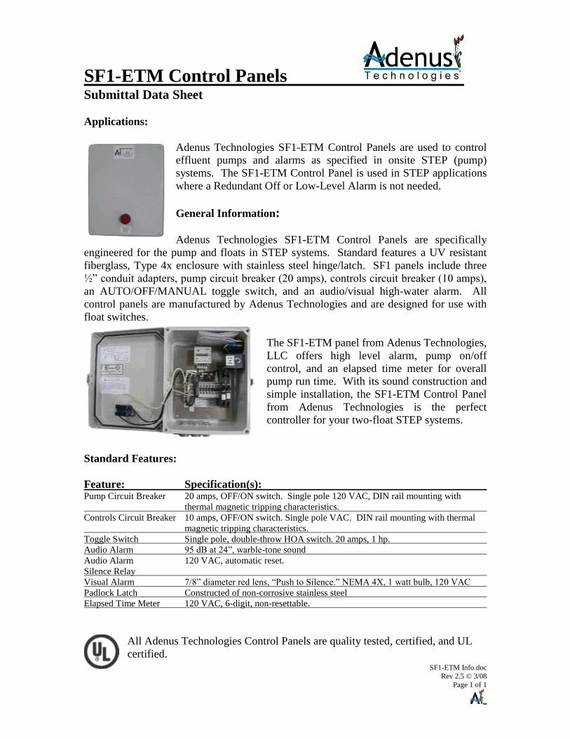
SF1-ETM Control Panels Submittal Data Sheet Applications:
Adenus Technologies SF1-ETM Control Panels are used to control
effluent pumps and alarms as specified in onsite STEP (pump)
systems. The SF1-ETM Control Panel is used in STEP applications
where a Redundant Off or Low-Level Alarm is not needed.
General Information:
Adenus Technologies SF1-ETM Control Panels are specifically
engineered for the pump and floats in STEP systems. Standard features a UV resistant
fiberglass, Type 4x enclosure with stainless steel hinge/latch. SF1 panels include three
½” conduit adapters, pump circuit breaker (20 amps), controls circuit breaker (10 amps),
an AUTO/OFF/MANUAL toggle switch, and an audio/visual high-water alarm. All
control panels are manufactured by Adenus Technologies and are designed for use with
float switches.
The SF1-ETM panel from Adenus Technologies,
LLC offers high level alarm, pump on/off
control, and an elapsed time meter for overall
pump run time. With its sound construction and
simple installation, the SF1-ETM Control Panel
from Adenus Technologies is the perfect
controller for your two-float STEP systems.
Standard Features:
Feature: Specification(s): Pump Circuit Breaker 20 amps, OFF/ON switch. Single pole 120 VAC, DIN rail mounting with
thermal magnetic tripping characteristics.
Controls Circuit Breaker 10 amps, OFF/ON switch. Single pole VAC. DIN rail mounting with thermal
magnetic tripping characteristics.
Toggle Switch Single pole, double-throw HOA switch. 20 amps, 1 hp.
Audio Alarm 95 dB at 24”, warble-tone sound
Audio Alarm 120 VAC, automatic reset.
Silence Relay
Visual Alarm 7/8” diameter red lens, “Push to Silence.” NEMA 4X, 1 watt bulb, 120 VAC
Padlock Latch Constructed of non-corrosive stainless steel
Elapsed Time Meter 120 VAC, 6-digit, non-resettable.
All Adenus Technologies Control Panels are quality tested, certified, and UL
certified.
Cons
tructi
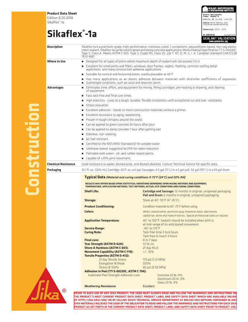
onSikaflex®-1aDescription Sikaflex-1aisapremium-grade,high-performance,moisture-cured,1-component,polyurethane-based,non-sagelasto-
mericsealant.Sikaflex-1acanbeusedingreenanddampconcreteapplications.MeetsFederalSpecificationTT-S-00230C,TypeII,ClassA.MeetsASTMC-920,TypeS,GradeNS,Class35,useT,NT,O,M,G,I,A.CanadianstandardCAN/CGSB19.13-M87.
Where to Use n Designedforalltypesofjointswheremaximumdepthofsealantwillnotexceed1/2in.
n Excellentforsmalljointsandfillets,windows,doorframes,reglets,flashing,commonroofingdetail applictions,andmanyconstructionadhesiveapplications.
n Suitableforverticalandhorizontaljoints;readilyplaceableat40°F n Has many applications as an elastic adhesive between materials with dissimilar coefficients of expansion.
n Submergedconditions,suchascanalandreservoirjoints.
Advantages nEliminatestime,effort,andequipmentformixing,fillingcartridges,pre-heatingorthawing,andcleaningofequipment.
n Fasttack-freeandfinalcuretimes.
n Highelasticity-curestoatough,durable,flexibleconsistencywithexceptionalcutandtear-resistance. n Stressrelaxation. n Excellentadhesion-bondstomostconstructionmaterialswithoutaprimer.
n Excellentresistancetoaging,weathering. nProvenintoughclimatesaroundtheworld.
n Canbeappliedtogreenconcrete24hoursafterpour n Canbeappliedtodampconcrete1houraftergettingwet
n Odorless,non-staining.
n Jetfuelresistant. n CertifiedtotheNSF/ANSIStandard61forpotablewater.
n Urethane-based;suggestedbyEPAforradonreduction. n Paintablewithwater-,oil-andrubber-basedpaints.
n Capableof±35%jointmovement.
Chemical Resistance Goodresistancetowater,dilutedacids,anddilutedalkalines.ConsultTechnicalServiceforspecificdata.
Packaging 10.1fl.oz.(300mL)Cartridge,20fl.oz.uni-pacSausages,4.5gal(17L)ina5galpail,52gal(197L)ina55galdrum
Product Data SheetEdition8.20.2018Sikaflex®-1a
Typical Data (Material and curing conditions @ 75°F (24°C) and 50% RH)
Shelf Life: Cartridge and Sausage: 12monthsinoriginal,unopenedpackaging. Pail and Drum: 6monthsinoriginal,unopenedpackaging.
Storage: Storeat40°-95°F(4°-35°C).
Product Conditioning: Conditionmaterialto65°-75°Fbeforeusing.
Colors: White,colonialwhite,aluminumgray,limestone,black,darkbronze, capitoltan,stoneandmediumbronze.Specialarchitecturalcolorsonrequest.
Application Temperature: 40°to100°F.Sealantshouldbeinstalledwhenjointis atmid-rangeofitsanticipatedmovement.
Service Range: -40°to170°FCuring Rate: Tack-freetime3to6hours Tack-freetotouch3hoursFinal cure: 4to7daysTear Strength (ASTM D-624): 55lb./in.Shore A Hardness (ASTM C-661): 21day45±5Movement Capability (ASTM C-719): +/-35%Tensile Properties (ASTM D-412): 21dayTensileStress 175psi(1.21MPa) Elongation@Break 550% Stress@100% 85psi(0.59MPa)Adhesion in Peel (TT-S-00230C, ASTM C 794): SubstratePeelStrengthAdhesionLoss Concrete20lb.0% Aluminum20lb.0% Glass20lb.0%Weathering Resistance Excellent
RESULTS MAY DIFFER BASED UPON STATISTICAL VARIATIONS DEPENDING UPON MIXING METHODS AND EQUIPMENT, TEMPERATURE, APPLICATION METHODS, TEST METHODS, ACTUAL SITE CONDITIONS AND CURING CONDITIONS.
PRIOR TO EACH USE OF ANY SIKA PRODUCT, THE USER MUST ALWAYS READ AND FOLLOW THE WARNINGS AND INSTRUCTIONS ON THE PRODUCT’S MOST CURRENT PRODUCT DATA SHEET, PRODUCT LABEL AND SAFETY DATA SHEET WHICH ARE AVAILABLE ONLINE AT HTTP://USA.SIKA.COM/ OR BY CALLING SIKA’S TECHNICAL SERVICE DEPARTMENT AT 800.933.7452 NOTHING CONTAINED IN ANY SIKA MATERIALS RELIEVES THE USER OF THE OBLIGATION TO READ AND FOLLOW THE WARNINGS AND INSTRUCTIONS FOR EACH SIKA PRODUCT AS SET FORTH IN THE CURRENT PRODUCT DATA SHEET, PRODUCT LABEL AND SAFETY DATA SHEET PRIOR TO PRODUCT USE.

Cons
tructi
onCoverage
How to UseSurface Preparation Cleanallsurfaces.Jointwallsmustbesound,clean,frost-free,andfreeofoilandgrease.Curingcompoundresiduesand
anyotherforeignmattermustbethoroughlyremoved.Aroughenedsurfacewillalsoenhancebond.Installbondbreakertapeorbackerrodtopreventbondatbaseofjoint.Primingisnotusuallynecessary.Mostsubstratesonlyrequireprimingiftestingindicatesaneedorwheresealantwillbesubjectedtowaterimmersionaftercure.
Forgreenconcreteapplicationscontroljointsmustbecut8hourspriortosealantinstallationandinexpansionjointformsmustberemoved4hourspriortosealantinstallation.Forwetconcreteapplicationsallexcessorstandingwatermustbedisplacedandconcretemustthendryforaminimumof60minpriortosealantinstallation.
ConsultSikaflexPrimerTechnicalDataSheetorTechnicalServiceforadditionalinformationonpriming.
Application Recommendedapplicationtemperatures:40°-100°F.Forcoldweatherapplication,conditionunitsatapproximately70°F;removepriortousing.Forbestperformance,Sikaflex-1ashouldbegunnedintojointwhenjointslotisatmid-pointofitsdesignedexpansionandcontraction.Placenozzleofgunintobottomofthejointandfillentirejoint.Keepthenozzleinthesealant,continueonwithasteadyflowofsealantprecedingthenozzletoavoidairentrapment.Avoidoverlappingofsealanttoeliminateentrapmentofair.
Sikaflex-1acanbeappliedongreenconcreteaftertheconcretehascuredforaminimumof24hoursat75°F.Controljointsmustbecutandopenforminof8hourspriortoapplication.Expansionjointsmusthaveformsremovedaminimumof4hourspriortoapplication.FordampconcreteapplicationsSikaflex-1acanbeapplied60minutesafteranyandallwaterhasbeendisplaced.
Tooling and Finishing Toolsealanttoensurefullcontactwithjointwallsandremoveairentrapment.Jointdimensionshouldallowfor1/4inchminimumand1/2inchmaximumthicknessforsealant.Properdesignis2:1widthtodepthratio,Foruseinhorizontaljointsintrafficareas,theabsoluteminimumdepthofthesealantis1/2in.andclosedcellbackerrodisrecommended.
Removal Usepersonalprotectiveequipment(chemicalresistantgloves/goggles/clothing).Withoutdirectcontact,removespilledorexcessproductandplacedinsuitablesealedcontainer.Disposeofexcessproductandcontainerinaccordancewithapplicableenvironmentalregulations.
Over Painting Allow1-weekcureatstandardconditionswhenusingSikaflex-1aintotalwaterimmersionsituationsandpriortopainting.
PRIOR TO EACH USE OF ANY SIKA PRODUCT, THE USER MUST ALWAYS READ AND FOLLOW THE WARNINGS AND INSTRUCTIONS ON THE PRODUCT’S MOST CURRENT PRODUCT DATA SHEET, PRODUCT LABEL AND SAFETY DATA SHEET WHICH ARE AVAILABLE ONLINE AT HTTP://USA.SIKA.COM/ OR BY CALLING SIKA’S TECHNICAL SERVICE DEPARTMENT AT 800.933.7452 NOTHING CONTAINED IN ANY SIKA MATERIALS RELIEVES THE USER OF THE OBLIGATION TO READ AND FOLLOW THE WARNINGS AND INSTRUCTIONS FOR EACH SIKA PRODUCT AS SET FORTH IN THE CURRENT PRODUCT DATA SHEET, PRODUCT LABEL AND SAFETY DATA SHEET PRIOR TO PRODUCT USE.
10.1 oz Cartridge: Yield in Linear feet
Depth 1/4" 3/8" 1/2"
Width
1/4" 24.3
3/8" 16.2 10.8
1/2" 12.1 8.1 6.1
3/4" 8.1 5.4 4.0
1" 3.0
1.25" 2.4
1.5" 2.0
20 oz Sausage: Yield in Linear feet
Depth 1/4" 3/8" 1/2"
Width
1/4" 48.1
3/8" 32.1 21.4
1/2" 24.1 16.0 12.0
3/4" 16.0 10.7 8.0
1" 6.0
1.25" 4.8
1.5" 4.0
1 gallon: Yield in Linear feet
Depth 1/4" 3/8" 1/2"
Width
1/4" 307.9
3/8" 205.3 136.8
1/2" 153.9 102.6 77.0
3/4" 102.6 68.4 51.3
1" 38.5
1.25" 30.8
1.5" 25.7

Cons
tructi
on
Visit our website at usa.sika.com 1-800-933-SIKA NATIONWIDERegional Information and Sales Centers.ForthelocationofyournearestSikasalesoffice,contactyourregionalcenter.
Sika Corporation Sika Canada Inc. Sika Mexicana S.A. de C.V. 201PolitoAvenue 601DelmarAvenue CarreteraLibreCelayaKm.8.5Lyndhurst,NJ07071 PointeClaire Fracc.IndustrialBalvaneraPhone:800-933-7452 QuebecH9R4A9 Corregidora,QueretaroFax:201-933-6225 Phone:514-697-2610 C.P.76920 Fax:514-694-2792 Phone:524422385800
Fax:524422250537
KEEP CONTAINER TIGHTLY CLOSED. KEEP OUT OF REACH OF CHILDREN. NOT FOR INTERNAL CONSUMPTION. FOR INDUSTRIAL USE ONLY. FOR PROFESSIONAL USE ONLY.
For further information and advice regarding transportation, handling, storage and disposal of chemical products, users should refer to the actual Safety Data Sheets containing physical, ecological, toxicological and other safety related data. Read the current actual Safety Data Sheet before using the product. In case of emergency, call CHEMTREC at 1-800-424-9300, International 703-527-3887.Prior to each use of any Sika product, the user must always read and follow the warnings and instructions on the product’s most current Product Data Sheet, product label and Safety Data Sheet which are available online at http://usa.sika.com/ or by calling Sika’s Technical Service Department at 800-933-7452. Nothing contained in any Sika materials relieves the user of the obligation to read and follow the warnings and instruction for each Sika product as set forth in the current Product Data Sheet, product label and Safety Data Sheet prior to product use.SIKA warrants this product for one year from date of installation to be free from manufacturing defects and to meet the technical properties on the current Product Data Sheet if used as directed within shelf life. User determines suitability of product for intended use and assumes all risks. Buyer’s sole remedy shall be limited to the purchase price or replacement of product exclusive of labor or cost of labor. NO OTHER WARRANTIESEXPRESS OR IMPLIED SHALL APPLY INCLUDING ANY WARRANTY OF MERCHANTABILITY OR FITNESS FOR A PARTICULAR PURPOSE. SIKA SHALL NOT BE LIABLE UNDER ANY LEGAL THEORY FOR SPECIAL OR CONSEQUENTIAL DAMAGES. SIKA SHALL NOT BE RESPONSIBLE FOR THE USE OF THIS PRODUCT IN A MANNER TO INFRINGE ON ANY PATENT OR ANY OTHER INTELLECTUAL PROPERTY RIGHTS HELD BY OTHERS.SALE OF SIKA PRODUCTS ARE SUBJECT SIKA’S TERMS AND CONDITIONS OF SALE AVAILABLE AT HTTP://USA.SIKA.COM/ OR BY CALLING 201-933-8800.
ISO 9001Certificate # FM 69711
RC 14001Certificate # RC 510999
PRIOR TO EACH USE OF ANY SIKA PRODUCT, THE USER MUST ALWAYS READ AND FOLLOW THE WARNINGS AND INSTRUCTIONS ON THE PRODUCT’S MOST CURRENT PRODUCT DATA SHEET, PRODUCT LABEL AND SAFETY DATA SHEET WHICH ARE AVAILABLE ONLINE AT HTTP://USA.SIKA.COM/ OR BY CALLING SIKA’S TECHNICAL SERVICE DEPARTMENT AT 800.933.7452 NOTHING CONTAINED IN ANY SIKA MATERIALS RELIEVES THE USER OF THE OBLIGATION TO READ AND FOLLOW THE WARNINGS AND INSTRUCTIONS FOR EACH SIKA PRODUCT AS SET FORTH IN THE CURRENT PRODUCT DATA SHEET, PRODUCT LABEL AND SAFETY DATA SHEET PRIOR TO PRODUCT USE.
Limitations n Allow1weekcureatstandardconditionswhenusingSikaflex-1aintotalwaterimmersionsituations.
n Whenovercoatingwithwater,oilandrubberbasedpaints,compatibilityandadhesiontestingisessential.
n Sealantshouldbeallowedtocurefor7dayspriortoovercoating
n Avoidexposuretohighlevelsofchlorine.(Maximumcontinuouslevelis5ppmofchlorine.)
n Maximumdepthofsealantmustnotexceed1/2in.;minimumdepthis1/4in.
n Maximumexpansionandcontractionshouldnotexceed35%ofaveragejointwidth.
n Donotcureinthepresenceofcuringsiliconesealants.
n Avoidcontactwithalcoholandothersolventcleanersduringcure.
n Donotapplywhenmoisture-vapor-transmissionconditionexistsfromthesubstrateasthiscancausebubbling withinthesealant.
n Useopenedcartridgesanduni-pacsausagesthesameday.
n Whenapplyingsealant,avoidair-entrapment.
n Sincesystemismoisture-cured,permitsufficientexposuretoair.
n Whitecolortendstoyellowslightlywhenexposedtoultravioletrays.
n Lightcolorscanyellowifexposedtodirectgasfiredheatingelement.
n TheultimateperformanceofSikaflex-1adependsongoodjointdesignandproperapplicationwithjointsurfaces properlyprepared.
nThedepthofsealantinhorizontaljointssubjecttotrafficis1/2in.
nDonottoolwithdetergentorsoapsolutions.
n Donotuseincontactwithbituminous/asphalticmaterials.
n Ingreenconcreteapplicationssealingjointsinpoororlowstrengthconcrete24hoursafterpourmayimpact abilityofsealanttogainproperadhesion.
n Indampconcreteapplicationsallstandingwaterandexcesswatermustbeeliminatedpriortothe60minute waitingtime.

TOP VIEW BOITOMVfEW
26"
SIOE\llEW CUT-A·WAYVI&/
<' 50>1 ' 31s;:r:lrit:=~· ;===== = ooo 1<::====='":: .. ::::===~>I
II U ''°"~=========~ ~~~~~~~~~>!
0.25 0.2S 22 75
FEATURES
+ IBl igh strength polycarbonate with 8000 lbs. wheel I oad in all weather condibons, H10 rabng
+ l!Baked urethane finish for positive uv protection and a hard durable surface lzyl.vailable in green or black)
+ llflat. non-slip diamond-plate surface + llPositive drop in feature ensures proper
cover and gasket alignment and makes installation easy
+ !$crews will not pull through even in extremely hot conditions
+ Ill holes and 4 drill able dim pies in two different hole patterns for universal fastening and the ability to fit multiple 24" diameter risers
+ 1$oft gasket provides good seal on various surfaces
+ lltan be easily installed with Styrofoam insulation for cold climates
+ lltan be attached to the bottom of our STF-R8248 segmented riser or to a 24" PVC well casing to create a pump basin
Order part No. STF-APC24B STF-APC24G
CAD detail draWng available in DXF fonnat
RELATED PRODUCTS STF-Cl24 page 5
STF-R824B page 9 STF-AR24 page 9 STF-11118 page 10 STF-11124 page 10 STF-11130 page 10
STF-APC24Gl-075 page 14 STF-APC24Bl-075 page 14 STF-APC24Gl-100 page 14 STF-APC24Bl-100 page 14
STF-APL24G page 14 STF-APL24B page 14
PAIZ Toll Free 888-999-3290 Office 231-582-1020 Fax 231-582-7324 Email simtech@free'Mly.net Web www.simtechfilter.com 6

Aug. 12 SStteepprrooss SSeellff CClleeaanniinngg VVaauulltt
Technical Specifications
• Polypropylene
• Schedule 40 PVC
• 1/8" solids or
smaller
• 15.3 ft² effective
screen area
Features
• Unique inside to
compliment
surface area
with ease of
cleaning and
removal of
buildup.
• Superior pump
protection
• Maximum
surface area to
ensure delivery
of water to the
pump
• Venturi effect
849 Aviation Parkway Smyrna,
TN 37167
615-427-1824
STEPROS'S maximum filter series designed to meet your filtration
requirements. Our filter is unique in design to benefit your
preventative maintenance program. Our maximum filter used in
conjunction with our Self Cleaning Flush Vault utilizies the venturi
effect to repel solids back into the tank instead of collecting them
thus providing longer periods of time between cleaning and
increasing life of the pump.