Embed Size (px)
Citation preview

Top-Up Experience at SPEAR3

• SPEAR 3 and the injector
• Top-up requirements
• Hardware systems and modifications
• Safety systems & injected beam tracking
• Interlocks & Diagnostics
Contents

3GeV Injector
BTS
5W, 1.6nA
E
W
N S
3GeV
10nm-rad
500 mA
Booster
(White
Circuit)
LINAC/RF Gun
10Hz
SPEAR3 Accelerator Complex
PXPD/XAS
SAXS/PX
XAFSNEXAFS
PX
PX
XAS/TXM
ARPES
EnvironmentXAS
CoherentSingle bunch/pulse

o Rebuild SPEAR into SPEAR3 (1999-2003)
o Operated at 100mA for ~6 years (beam line optics)
o Recently increased to 200mA
o Chamber components get hot at 500ma (450kW SR, impedance)
o 500mA program suspended because of
power load transient on beam line optics
o Instead worked to top-off mode (beam decay mode, fill-on-fill)
Top ‘off’ at SPEAR3
RF system and vacuum chamber rated for 500ma

o 13 exit ports taking SR (9 Insertion Device, 4 Dipole)
o 7 ID ports presently in „fill-on-fill‟ open shutter mode
o 4 dipole beam lines open shutter injection by end of October 2009
o Last two ID shutters fill-on-fill by June 2010
o Trickle charge 2011
Present Status
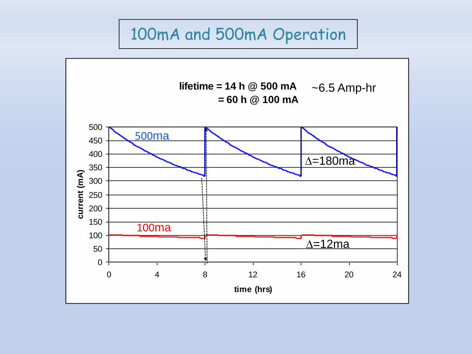
SPEAR 3 100 vs. 500 mA Fill Scenarios
lifetime = 14 h @ 500 mA
= 60 h @ 100 mA
0
50
100
150
200
250
300
350
400
450
500
0 4 8 12 16 20 24
time (hrs)
cu
rren
t (m
A)
100mA and 500mA Operation
=12ma
=180ma
100ma
500ma
~6.5 Amp-hr

delivery time = 8 hr
tfill = ~6-7 min
delivery time = 2 hr
tfill = ~1.5-2 min
SPEAR 3 500 mA Fill Scenario
lifetime = 14 h @ 500 mA
0
50
100
150
200
250
300
350
400
450
500
0 6 12 18 24
time (hrs)
curr
ent
(mA
)
delivery time = 0.5 hr
tfill = ~17 sec
SPEAR 3 500 mA Fill Scenario
lifetime = 14 h @ 500 mA
0
50
100
150
200
250
300
350
400
450
500
0 6 12 18 24
time (hrs)
curr
ent
(mA
)
delivery time = 1 min
tfill = ~0.5 sec
(or 10ms single shot)
500mA Injection Scenarios

RF
B132-102
B116-
101
B117
control
roomB118
power
suppliesSLM
room
B132-101
B120
B131
B130
3 GeV
Booster
120 MeV
linac
B140
LTB
BTS
RF
HVP
S
• Gun
o higher current
o stablize emission rate
o “laser-assisted” emission
• Linac
o restore 2nd klystron
(higher energy, feedback)
o phase-lock linac and booster rf
• Booster
o improve capture with modified lattice
o improve orbit and tune monitors
o develop fast turn-on mode
• BTS
o eliminate vacuum windows (done)
o diagnostics
• SPEAR
o add shielding, interlocks
o improve kicker response
o transverse feedback
• Beamlines
o add shielding, interlocks
o timing
Hardware Upgrades

• Vertical Lambertson septum (booster outside ring)
- operates DC, skew quadrupole added
• Three magnet bump
• ~15 mm amplitude, ~12mm separation
• Injection across three cells (sextupoles)
• Slotted stripline kickers (DELTA, low impedance)
• Transverse field dependence in K2
SPEAR3 Injection Notes
Elevation viewPlan view
Injected beam
Stored beam

Se
ptu
m w
all
Se
ptu
m w
all
With windows: ~20% beam loss No windows: ~no loss
Hardware Upgrade: BTS Windows
Huang & Safranek

Injected beam profile measurements
Turn number
Movies…
Visible diagnostic beam line

• Synchrotron oscillations measured with turn-by-turn BPMs:
• Kickers set to dump injected beam each cycle
• Injection energy stable
• Injection time varies over hours– RF cable temperature
• Develop method to measure timing with stored beam
Before correction After correction
Hardware upgrade: Injection Timing and Energy
Huang, Safranek & Sebek

V
H
mS
V
H
mS
Single shot
injection kicker transient = ~10 ms
(~0.1 ms with feedback)
• Kickers can interrupt data acquisition
o What is interruption sequence?
• depends on current ripple, beam lifetime and charge/shot
• bunch train filling needs new booster RF system
o Gated data acquisition
o Tests with beam lines no complaints
o Lots of work to match kicker waveforms
Hardware upgrade: Injection Bump Closure
Huang & Safranek

downconverter schematic
Hardware Upgrade: PEP-II Bunch Current Monitor
bunch-by-bunch processor chassis
- visible APD (ASP)- x-ray APD (CLS)
downconverter chassis
A.S.Fisher

► S-band RF gun with thermionic cathode, alpha magnet, and chopper
► Most charge during the 2 μs RF pulse stopped at the chopper
► 5-6 S-band buckets pass into the linac, single booster bucket
► SPEAR3 single bunch injection, 10Hz presently ~50pC/shot
2.856 GHz (2 s)
e- beamTungsten
dispenser-cathode
(1000 C)
1.5 cell RF gun
Hardware Upgrade: Thermionic Cathode as a Photo-Emitter
Nominal configuration

► high singe-bunch charge for top-off
- reduce beam loading in linac
- eliminate cathode back bombardment
- eliminate chopper
2.856 GHz (~2 s)
e- beam (~500ps)cold-cathode
UV or green laser
UV Green
1.5W heating
Sara Thorin/MAXLab, EPAC'08
'Turning the thermionic gun into a photo injector
has been very successful '
1.5 cell RF gun
Photo-emission cathode (cont’d)
Laser-driven configuration
Cu
S.Gierman

• Radiation Safety: the first hurdle
o AP studies to demonstrate injected beam can not escape shielding
o Many clever scenarios (dreams and zebras)
o BL shielding sufficient? (higher average current, more bremsstrahlung)
o PPS/BCS interlock modifications
o Do users wear badges?
• Efficient injection into main ring
o Injection time, charge/shot, repetition rate
The Injected Beam Safety Dilemma
Safety is complicated!

18
SPEAR3 DBA cell
Synchrotron Radiation Exit Ports

V4 MASK
V1, V2 MASKS
BPMs
H2 ABSORBER
TSPs
EDDY CURRENT
BREAK
BM-2
QFC
BM-1
220 L/S
ION PUMP
150 L/S
ION PUMP
TSP
V3 MASK
BELLOWS
BELLOWS
H1 ABSORBER H3 ABSORBER
TSP
BPM
BPM
BPM
ID BPM
ADDITIONAL
BPM SET
220 L/S
ION PUMP
84 mm
44.2
mm
34
mm
24 mm13 mm18.8 mm
ID BPM
BPM
Vacuum Chamber Construction

e- beam
photon beam
outside absorber
inside absorber
Photon Beam Exit Channel

A Closer Look…

22
X-Rays
Injected Beam
X-Rays
Stored Beam
NORMAL
X-Rays
Injected Beam
X-Rays
Stored Beam
Injected Beam
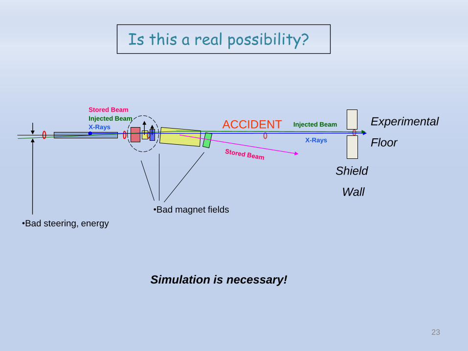
ACCIDENT
Stored Beam
X-Rays
Injected Beam
X-Rays
Injected Beam
Ratchet
WallFixed
Mask
Top-Up with Safety Shutters Open
SAFE
23
X-Rays
Injected Beam
X-Rays
Stored Beam
Injected BeamACCIDENT
•Bad steering, energy
Experimental
Floor
Simulation is necessary!
Is this a real possibility?
•Bad magnet fields
Shield
Wall
QF QD BEND SDINSERTION DEVICE
A1 A2
Stored Beam on
design orbit
Ratchet
WallFixed
Mask I
Fixed
Mask IIComb
Mask 9.1
CM
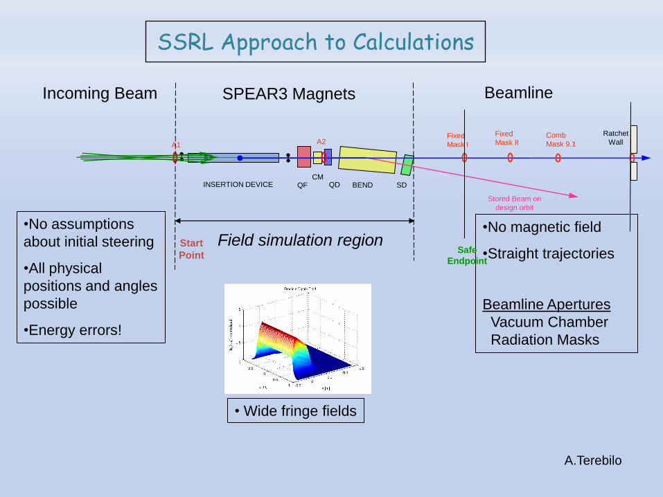
SPEAR3 Magnets BeamlineIncoming Beam
•No assumptions
about initial steering
•All physical
positions and angles
possible
•Energy errors!
•No magnetic field
•Straight trajectories
Beamline Apertures
Vacuum Chamber
Radiation Masks
Safe
Endpoint
Start
Point
Field simulation region
SSRL Approach to Calculations
• Wide fringe fields
A.Terebilo

25
A1 Aperture
A2 Aperture
Fixed Mask
Stored Beam
Injected Beam
Ratchet Wall
(2-ft Concrete)
Forward Propagation Only
Chamber boundary
26
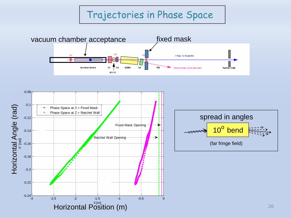
-3 -2.5 -2 -1.5 -1 -0.5 0-0.24
-0.22
-0.2
-0.18
-0.16
-0.14
-0.12
-0.1
-0.08
X [m]
X' [r
ad]
Phase Space at Z = Fixed Mask
Phase Space at Z = Ratchet Wall
Fixed Mask Opening
Ratchet Wall Opening
Horizontal Position (m)
Horizonta
l Angle
(ra
d)
vacuum chamber acceptance fixed mask
10 bendo
spread in angles
(far fringe field)
Trajectories in Phase Space

27
-0.06 -0.04 -0.02 0 0.02 0.04 0.06 0.08 0.1-0.8
-0.6
-0.4
-0.2
0
0.2
0.4
0.6
0.8
1
X [m]
X' [r
ad]
Initial: A1 and BPM7
After BPM1
-0.08 -0.06 -0.04 -0.02 0 0.02 0.04 0.06 0.08 0.1 0.12-0.04
-0.03
-0.02
-0.01
0
0.01
0.02
0.03
0.04
0.05
X [m]
X' [r
ad]
BPM1
After QF
A2
Dipole Entrance
-0.15 -0.1 -0.05 0 0.05 0.1 0.15 0.2-0.04
-0.02
0
0.02
0.04
0.06
0.08
0.1
X [m]
X' [r
ad]
Dipole Entrance
Dipole Exit
SD Exit
-3 -2.5 -2 -1.5 -1 -0.5 0-0.24
-0.22
-0.2
-0.18
-0.16
-0.14
-0.12
-0.1
-0.08Allowed Phase Space in BL coordinates
X [m]
X' [r
ad]
Z = SD exit
Z = Fixed Mask
Z = Ratchet Wall
QF QD BEND SDInsertion Device HCOR
A1 A2
Stored Beam on design orbit
X-Rays to Beamline
Ratchet
WallFixed
Mask I
BPM 7 BPM 1
Evolution of allowed phase space

28
-3 -2.5 -2 -1.5 -1 -0.5 0-0.24
-0.22
-0.2
-0.18
-0.16
-0.14
-0.12
-0.1
-0.08
X [m]
X' [r
ad]
Phase Space at Z = Fixed Mask
Phase Space at Z = Ratchet Wall
Fixed Mask Opening
Ratchet Wall Opening
The Metric: Separation in Phase Space to Apertures

29
A1
QF QD BEND SD
ID A2BPM 7 BPM 1
Stored Beam
on design orbit
Beamline Axis
Extreme Ray
4 6 8 10 12 14 16-1.4
-1.2
-1
-0.8
-0.6
-0.4
-0.2
0
Z [m]
BL a
pert
ure
s a
nd E
xtr
em
e R
ay p
ositio
n [
m]
Beamline apertures and the most severely mis-steered beam
BL4
BL5
BL6
BL7
BL9
BL10
BL11
mis-steered beam
Extreme Ray
All other
Trajectories
The Extreme Ray
Position along beam line [m]
rise/run ~ -0.1 rad
ratchet wall
Offset [
m]
Separation at
Fixed Mask
beam pipe w/apertures

30
Large SPEAR3 magnet field error
- and/or -
Large injected beam energy error
- AND -
“extensive intentional steering”
Condition for ‘Abnormal’ Scenario
special SLAC interpretation

4 6 8 10 12 14 16-1.2
-1
-0.8
-0.6
-0.4
-0.2
0
0.2
Z[m] from ID center
BL a
pert
ure
and E
xtr
em
e R
ay p
ositio
n [
m]
BL5
BL6
BL7
BL9
BL10
BL11
Nominal
B/B = -10%
B/B = -50%
B/B = -60%
Parameter To Pass Beyond Fixed
Mask
To Pass Beyond
Ratchet Wall
Target Value for
Interlock Limit
EINJ/ESPEAR +59% +100% +10%
B/B -48% -60% -1% (-10%)
QF -100% Only with polarity
reversed
-25%
QD +300% 55% (PS Limit)
HCOR 22 mrad 30 mrad 3mrad (2 x PS Limit)
Parameter Sensitivity

QF QD BEND SDInsertion Device HCOR
A1 A2 A3
Stored Beam on design orbit
X-Rays to Beamline
Ratchet Wall
PM
+60 / -43 mm +50 / -43 mm BL9: +112 / -101 mm
SPEAR
Apertures
Beamline-Specific
Aperture
Alignment of Apertures is Critical

33
Fixed
Mask
ID sourceRing
Aperture
Experimental Floor
xxx
Mechanical Drawings & Tolerances
Documentation
Periodic checks
More documentation

Dose Calculations & Testing
Bauer & Liu
mis-steer and measure…

35
Passive Systems
-Limiting apertures in transport line (BTS)
-Limiting apertures in SPEAR3 and beam lines
- Permanent magnets for dipole beam lines
Active Systems (Redundant Interlocks)
- Injection energy interlock
- BTS dipole supply
- SPEAR3 magnet supplies
- Stored beam interlock
- Radiation detectors at each beam line
‘Hazard Mitigation’

Hardware Interlock Envelope
Software Alarm Envelope
A
B
* *
path 1
path 2
Software Monitor Envelope
Interlock Hierarchy
(reportable incident)

A Rastafarian Logic Table
Corbett & Schmerge

1. Load operational lattice
- software check of PS readbacks
2. Inject to <20 mA (orbit interlock)
3. Start orbit feedback (few microns)
4. Inject to 50 mA – top-off permit
5. Open beam line injection stoppers
6. Fill 500 mA maximum (FOFB runs continuous)
7. Fill-on-fill or trickle charge
SPEAR3 Operating Sequence