Embed Size (px)
Citation preview


Top file: Block Diagram
P1shades(5:0) and P2Shades(5:0) allow the userto change the color of their pieces other than the standard red and blue.
Resetn- common anode button (used for resetting)
Clk- clock set at 100 Mhz
Right, left and Drop are all buttons on the Nexys4. Right and left serve as Index selector inputs that allow the user to see where he/she is about to drop there piece.
Drop places the users Indexed piece into place.
R,G,B, HS and VS are output data signals to the VGA screen
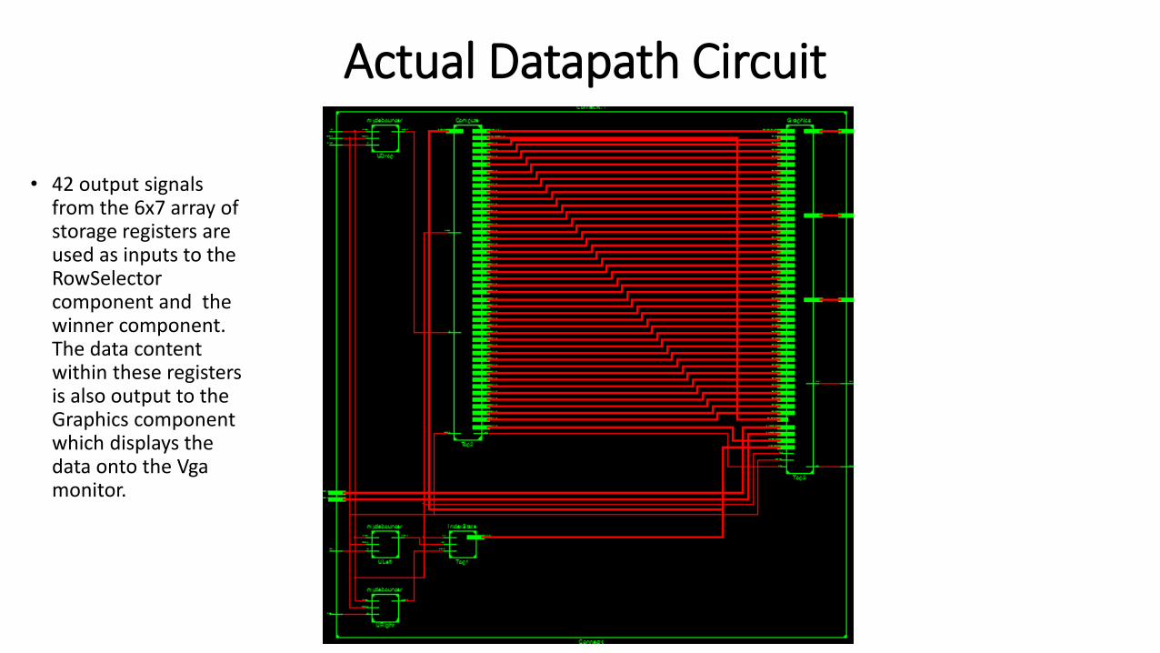
Actual Datapath Circuit
• 42 output signals from the 6x7 array of storage registers are used as inputs to the RowSelectorcomponent and the winner component. The data content within these registers is also output to the Graphics component which displays the data onto the Vgamonitor.

Simplified Datapath Circuit
• This circuit only contains one register. The original contains 42 separate output signals to all of the components in the Compute file.
• This image is just for demonstrative purposes.

Debouncers with IndexState datapath
Left and right buttonsAre smoothened outTo get rid of mechanicalBouncing, they are then Fed into the IndexStateComponent which actsAs a decoder to representEach index position above the Connect 4 game board.

X_index Selector

Compute: Datapath circuit Simplified

PlayerSwitcherState Machine

5
4
3
2
1
0
Y_dim0 1 2 3 4 5 6
X_dim
Reg00
Reg65
Reg63
Reg30
The 6x7 Grid of Registers and their Naming Convention

End to end Test done by the Compute (TestBench Included)
Move 1

Move 2

Move 3

Move 4

Move 5
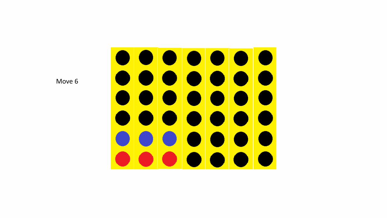
Move 6

Move 7

Timing Simulation Depicting each of the 7 turns and their corresponding values of “red=10” and “blue=01” being saved into each register.

TestBench Code-Reset is pressed, it instantiates all the registers with values of “00”
-Player one goes in the Left bottom corner
-Player two goes above his last move.
-Player one goes one index to the right.
-Player two goes above his last move.
-Player two goes above his last move.
-Player one goes one index to the right.
-Player one goes one index to the right.

Graphics: Datapath Circuit SimplifiedThis circuit takes 49 inputs total. 42 inputs from the register contentsContaining a specific value for a Color: red=10 and blue=01.The value is then decoded into12 bit RGB and used as an inputTo a 42x1 Multiplexor.
The multiplexor’s selector is basedUpon HC and VC values which areOutput from the VGA_ctrl_12b.HC and VC give reference to theX and y coordinates on the VGA Screen.
The VGA_ctrl_12b then outputs R,G, B, Hs and V to a Vga monitor.