Embed Size (px)
Citation preview
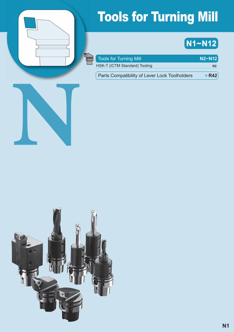
Tools for Turning Mill
N1~N12N1~N12
N1
HSK-T (ICTM Standard) Tooling N2
Tools for Turning Mill N2~N12
Parts Compatibility of Lever Lock Toolholders R42
N2
N
Tool
s fo
r Tur
ning
Mill
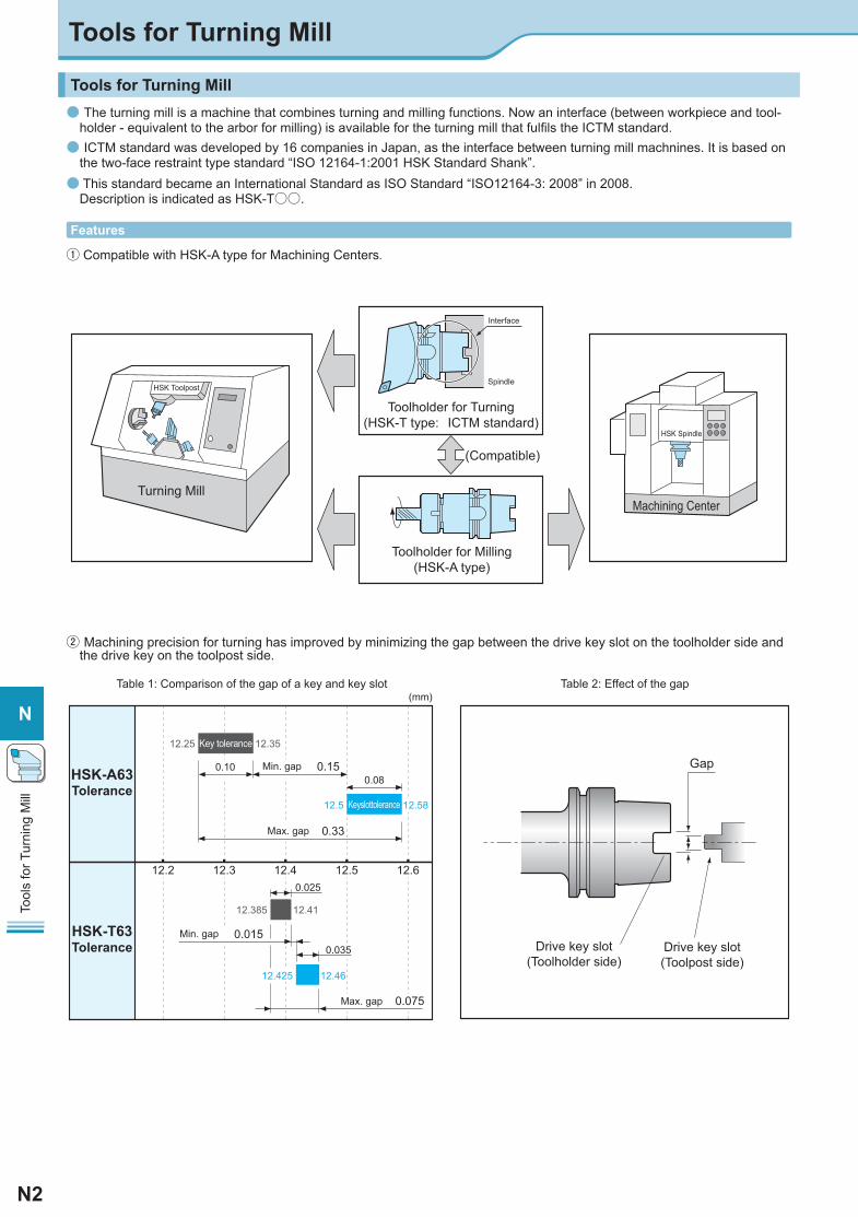
Tools for Turning Mill● The turning mill is a machine that combines turning and milling functions. Now an interface (between workpiece and tool-
holder - equivalent to the arbor for milling) is available for the turning mill that fulfi ls the ICTM standard.● ICTM standard was developed by 16 companies in Japan, as the interface between turning mill machnines. It is based on
the two-face restraint type standard “ISO 12164-1:2001 HSK Standard Shank”.● This standard became an International Standard as ISO Standard “ISO12164-3: 2008” in 2008.
Description is indicated as HSK-T○○.
HSK-A63Tolerance
HSK-T63Tolerance
Keyslottolerance
Key tolerance
Min. gap
12.2 12.3
0.150.10
Min. gap 0.015
Max. gap 0.33
Max. gap 0.075
0.025
0.035
0.08
(mm)
12.5812.5
12.4612.425
12.3512.25
12.4112.385
12.512.4 12.6
Gap
Drive key slot(Toolpost side)
Drive key slot(Toolholder side)
Toolholder for Turning(HSK-T type: ICTM standard)
(Compatible)
Turning MillMachining Center
HSK Toolpost
HSK Spindle
Interface
Spindle
Toolholder for Milling(HSK-A type)
Table 1: Comparison of the gap of a key and key slot Table 2: Effect of the gap
Features
① Compatible with HSK-A type for Machining Centers.
② Machining precision for turning has improved by minimizing the gap between the drive key slot on the toolholder side and the drive key on the toolpost side.
Tools for Turning Mill
N3
N
Tool
s fo
r Tur
ning
Mill
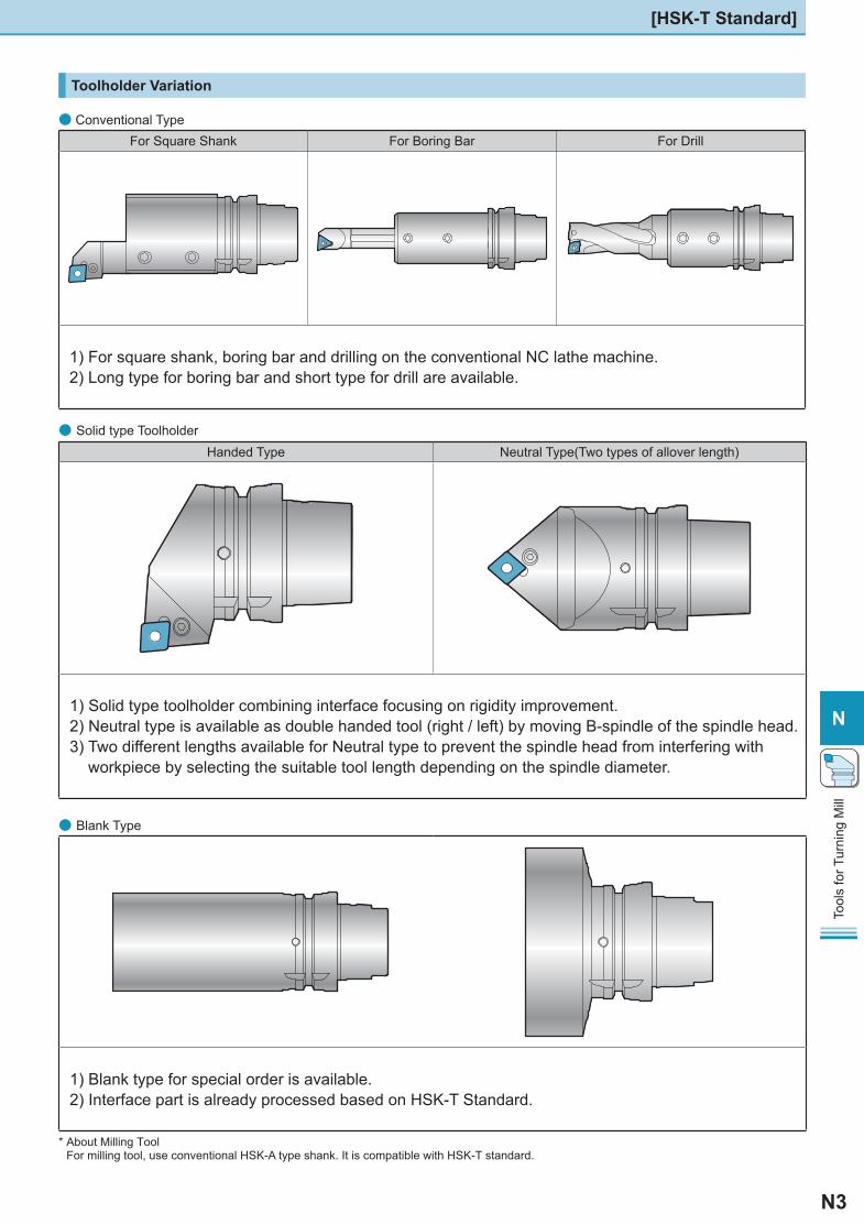
● Solid type ToolholderHanded Type Neutral Type(Two types of allover length)
1) Solid type toolholder combining interface focusing on rigidity improvement.2) Neutral type is available as double handed tool (right / left) by moving B-spindle of the spindle head.3) Two different lengths available for Neutral type to prevent the spindle head from interfering with
workpiece by selecting the suitable tool length depending on the spindle diameter.
● Conventional Type For Square Shank For Boring Bar For Drill
1) For square shank, boring bar and drilling on the conventional NC lathe machine. 2) Long type for boring bar and short type for drill are available.
● Blank Type
1) Blank type for special order is available.2) Interface part is already processed based on HSK-T Standard.
* About Milling ToolFor milling tool, use conventional HSK-A type shank. It is compatible with HSK-T standard.
Toolholder Variation
[HSK-T Standard]
N4
N
Tool
s fo
r Tur
ning
Mill
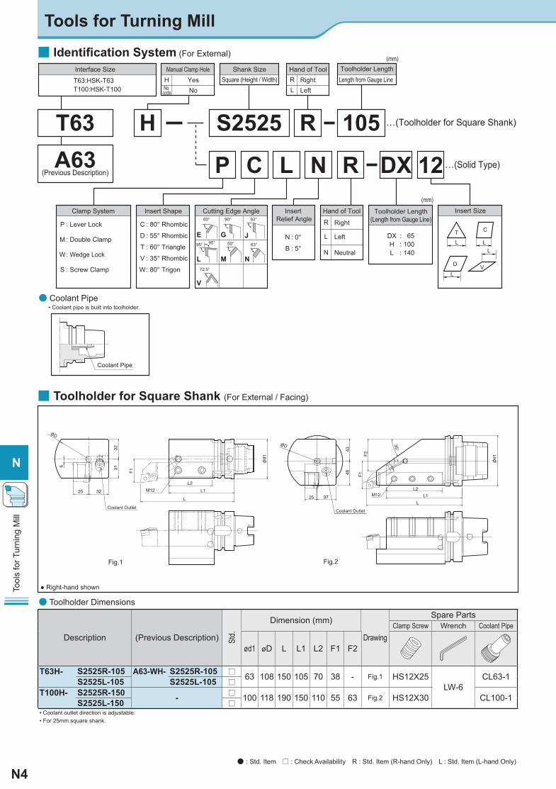
● Coolant Pipe
Insert Size
DXHL
: : :
65100140
12…(Solid Type)
…(Toolholder for Square Shank)
L
D
LV
T
L
C
L
Cutting Edge Angle Toolholder Length(Length from Gauge Line)R
L
Right
Left
N Neutral
DXRNLCP
S2525 R 105T63A63
(Previous Description)
H
Hand of Tool
RL
RightLeft
Hand of Tool
C
D
T
V
W
: 80° Rhombic
: 55° Rhombic
: 60° Triangle
: 35° Rhombic
: 80° Trigon
Insert Shape
H YesNo
Manual Clamp HoleSquare (Height / Width)
Shank SizeLength from Gauge Line Toolholder Length
P
M
W
S
: Lever Lock
: Double Clamp
: Wedge Lock
: Screw Clamp
Clamp System
N
B
: 0°
: 5°
Insert Relief Angle
E G J
L N
V
M
60° 90° 93°
95° 95° 50°
72.5°
63°
(mm)
(mm)Interface Size
T63:HSK-T63T100:HSK-T100 No
code
• Coolant pipe is built into toolholder.
Coolant Pipe
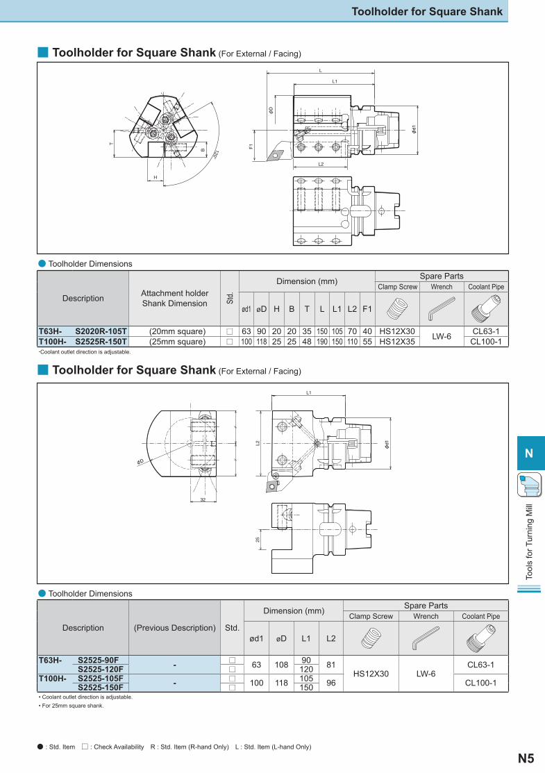
■ Toolholder for Square Shank (For External / Facing)
M12
Coolant Outlet
L2
L1
6
25
3231
32
L
F1
φD
Fig.1
φd1
● Right-hand shown
■ Identifi cation System (For External)
φd1
4843
F1
F2
35°
L2
L1
L3725 M12
φD
Coolant Outlet
Fig.2
● Toolholder Dimensions
Description (Previous Description) Std.
Dimension (mm)
Drawing
Spare PartsClamp Screw Wrench Coolant Pipe
ød1 øD L L1 L2 F1 F2
T63H- S2525R-105 A63-WH- S2525R-105 □ 63 108 150 105 70 38 - Fig.1 HS12X25LW-6
CL63-1S2525L-105 S2525L-105 □T100H- S2525R-150 - □ 100 118 190 150 110 55 63 Fig.2 HS12X30 CL100-1S2525L-150 □• Coolant outlet direction is adjustable.• For 25mm square shank.
Tools for Turning Mill
● : Std. Item □ : Check Availability R : Std. Item (R-hand Only) L : Std. Item (L-hand Only)
N5
N
Tool
s fo
r Tur
ning
Mill
■ Toolholder for Square Shank (For External / Facing)
Description Attachment holderShank Dimension St
d.
Dimension (mm) Spare Parts Clamp Screw Wrench Coolant Pipe
ød1 øD H B T L L1 L2 F1
T63H- S2020R-105T (20mm square) □ 63 90 20 20 35 150 105 70 40 HS12X30 LW-6 CL63-1T100H- S2525R-150T (25mm square) □ 100 118 25 25 48 190 150 110 55 HS12X35 CL100-1・Coolant outlet direction is adjustable.
φ
φ
● Toolholder Dimensions
Description (Previous Description) Std.
Dimension (mm) Spare Parts Clamp Screw Wrench Coolant Pipe
ød1 øD L1 L2
T63H- S2525-90F - □ 63 108 90 81HS12X30 LW-6
CL63-1S2525-120F □ 120T100H- S2525-105F - □ 100 118 105 96 CL100-1S2525-150F □ 150• Coolant outlet direction is adjustable. • For 25mm square shank.
■ Toolholder for Square Shank (For External / Facing)φ
φ
● Toolholder Dimensions
Toolholder for Square Shank
● : Std. Item □ : Check Availability R : Std. Item (R-hand Only) L : Std. Item (L-hand Only)
N6
N
Tool
s fo
r Tur
ning
Mill
Applicable Insert
DNGA
1504..
DNGGDNMADNMGDNMMDNMP
Applicable Insert
CNGA
1204..
CNGGCNMACNMGCNMMCNMP
Applicable Insert
CNGA
1204..
CNGGCNMACNMGCNMMCNMP
6°
5°
L1
F1
5°
31
φ63
6°
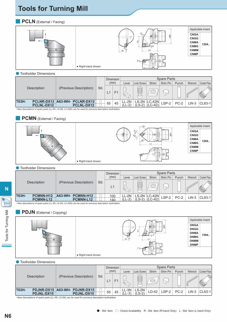
■ PCLN (External / Facing)
● Right-hand shown
Description (Previous Description) Std.
Dimension(mm)
Spare Parts Lever Lock Screw Shim Shim Pin Punch Wrench Coolant Pipe
L1 F1
T63H- PCLNR-DX12 A63-WH- PCLNR-DX12 □ 65 45 LL-2N(LL-2)
LS-2N(LS-2)
LC-42N(LC-42) LSP-2 PC-2 LW-3 CL63-1PCLNL-DX12 PCLNL-DX12 □
• New descriptions of spare parts (LL-2N, LS-2N, LC-42N) can be used for previous description toolholders.
● Toolholder Dimensions
■ PCMN (External / Facing)
Description (Previous Description) Std.
Dimension(mm)
Spare Parts Lever Lock Screw Shim Shim Pin Punch Wrench Coolant Pipe
L1
T63H- PCMNN-H12 A63-WH- PCMNN-H12 □ 100 LL-2N(LL-2)
LS-2N(LS-2)
LC-42N(LC-42) LSP-2 PC-2 LW-3 CL63-1PCMNN-L12 PCMNN-L12 □ 140
• New descriptions of spare parts (LL-2N, LS-2N, LC-42N) can be used for previous description toolholders.
● Toolholder Dimensions φ
● Right-hand shown
■ PDJN (External / Copying)
Description (Previous Description) Std.
Dimension(mm)
Spare Parts Lever Lock Screw Shim Shim Pin Punch Wrench Coolant Pipe
L1 F1
T63H- PDJNR-DX15 A63-WH- PDJNR-DX15 □65 45 LL-3N
(LL-3)LS-2N(LS-2) LD-42 LSP-2 PC-2 LW-3 CL63-1PDJNL-DX15 PDJNL-DX15 □
• New descriptions of spare parts (LL-3N, LS-2N) can be used for previous description toolholders.
● Toolholder Dimensions
φ
Tools for Turning Mill
● Right-hand shown
● : Std. Item □ : Check Availability R : Std. Item (R-hand Only) L : Std. Item (L-hand Only)
N7
N
Tool
s fo
r Tur
ning
Mill
Applicable Insert
DNGA
1504..
DNGGDNMADNMGDNMMDNMP
Applicable Insert
TNGA
1604..
TNGGTNMATNMGTNMMTNMP
Applicable Insert
TNGA
1604..
TNGGTNMATNMGTNMMTNMP
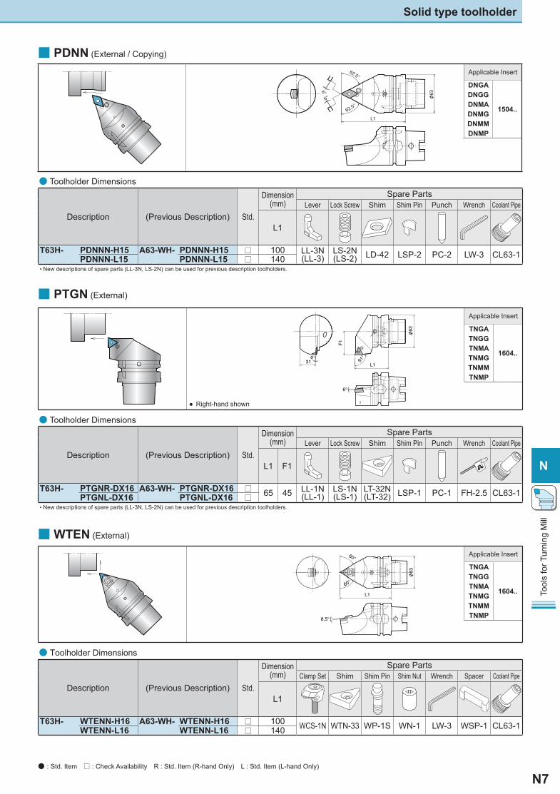
■ PDNN (External / Copying)
φ
Description (Previous Description) Std.
Dimension(mm)
Spare Parts Lever Lock Screw Shim Shim Pin Punch Wrench Coolant Pipe
L1
T63H- PDNNN-H15 A63-WH- PDNNN-H15 □ 100 LL-3N(LL-3)
LS-2N(LS-2) LD-42 LSP-2 PC-2 LW-3 CL63-1PDNNN-L15 PDNNN-L15 □ 140
• New descriptions of spare parts (LL-3N, LS-2N) can be used for previous description toolholders.
● Toolholder Dimensions
■ PTGN (External)
φ● Right-hand shown
Description (Previous Description) Std.
Dimension(mm)
Spare Parts Lever Lock Screw Shim Shim Pin Punch Wrench Coolant Pipe
L1 F1
T63H- PTGNR-DX16 A63-WH- PTGNR-DX16 □ 65 45 LL-1N(LL-1)
LS-1N(LS-1)
LT-32N(LT-32) LSP-1 PC-1 FH-2.5 CL63-1PTGNL-DX16 PTGNL-DX16 □
• New descriptions of spare parts (LL-3N, LS-2N) can be used for previous description toolholders.
● Toolholder Dimensions
■ WTEN (External)
Description (Previous Description) Std.
Dimension(mm)
Spare Parts Clamp Set Shim Shim Pin Shim Nut Wrench Spacer Coolant Pipe
L1
T63H- WTENN-H16 A63-WH- WTENN-H16 □ 100 WCS-1N WTN-33 WP-1S WN-1 LW-3 WSP-1 CL63-1WTENN-L16 WTENN-L16 □ 140
● Toolholder Dimensions
φ
Solid type toolholder
● : Std. Item □ : Check Availability R : Std. Item (R-hand Only) L : Std. Item (L-hand Only)

N8
N
Tool
s fo
r Tur
ning
Mill
Description (Previous Description) Std.
Dimension(mm)
Spare Parts Lever Lock Screw Shim Shim Pin Punch Wrench Coolant Pipe
L1 F1
T63H- PWLNR-DX08 A63-WH- PWLNR-DX08 □65 45 LL-2N
(LL-2)LS-2N(LS-2)
LW-42N(LW42) LSP-2 PC-2 LW-3 CL63-1
PWLNL-DX08 PWLNL-DX08 □• New descriptions of spare parts (LL-2N, LS-2N, LW-42N) can be used for previous description toolholders.
● Toolholder Dimensions
■ WWMN (External / Facing)
φ
Description (Previous Description) Std.
Dimension(mm)
Spare Parts Clamp Set Shim Shim Pin Shim Nut Wrench Coolant Pipe
L1
T63H- WWMNN-H08 A63-WH- WWMNN-H08 □ 100WCS-8 WWN-42 WP5X15 WN-1 LW-3 CL63-1
WWMNN-L08 WWMNN-L08 □ 140
● Toolholder Dimensions
■ PWLN (External / Facing)
φ
● Right-hand shown
Applicable Insert
WNGA
0804..WNMAWNMGWNMMWNMP
Applicable Insert
WNGA
0804..WNMAWNMGWNMMWNMP
Tools for Turning Mill
● : Std. Item □ : Check Availability R : Std. Item (R-hand Only) L : Std. Item (L-hand Only)
N9
N
Tool
s fo
r Tur
ning
Mill
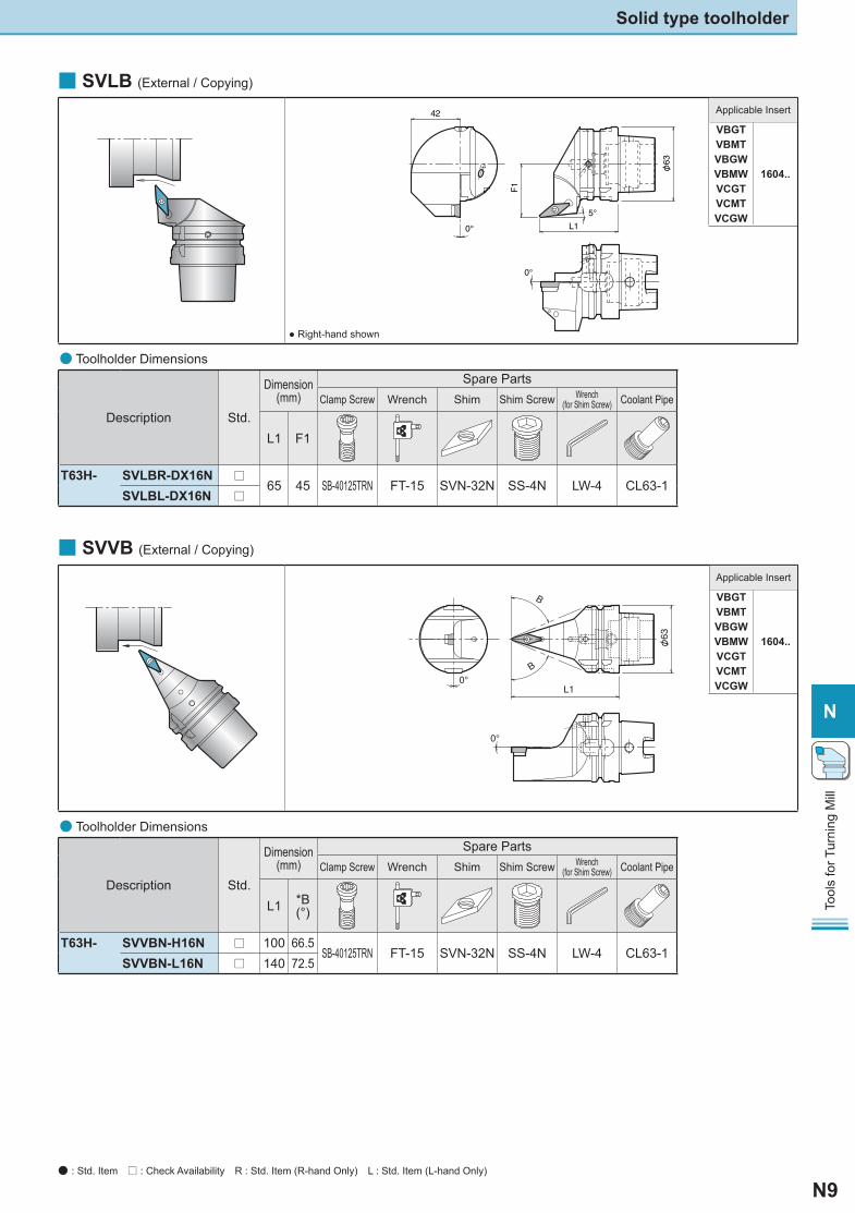
Description Std.
Dimension(mm)
Spare PartsClamp Screw Wrench Shim Shim Screw Wrench
(for Shim Screw) Coolant Pipe
L1 F1
T63H- SVLBR-DX16N □65 45 SB-40125TRN FT-15 SVN-32N SS-4N LW-4 CL63-1
SVLBL-DX16N □
■ SVLB (External / Copying)
φ
● Right-hand shown
● Toolholder Dimensions
■ SVVB (External / Copying)
φ
Applicable Insert
VBGT
1604..
VBMTVBGWVBMWVCGTVCMTVCGW
Description Std.
Dimension(mm)
Spare Parts
Clamp Screw Wrench Shim Shim Screw Wrench (for Shim Screw) Coolant Pipe
L1 *B (°)
T63H- SVVBN-H16N □ 100 66.5SB-40125TRN FT-15 SVN-32N SS-4N LW-4 CL63-1
SVVBN-L16N □ 140 72.5
● Toolholder Dimensions
Solid type toolholder
Applicable Insert
VBGT
1604..
VBMTVBGWVBMWVCGTVCMTVCGW
● : Std. Item □ : Check Availability R : Std. Item (R-hand Only) L : Std. Item (L-hand Only)
N10
N
Tool
s fo
r Tur
ning
Mill
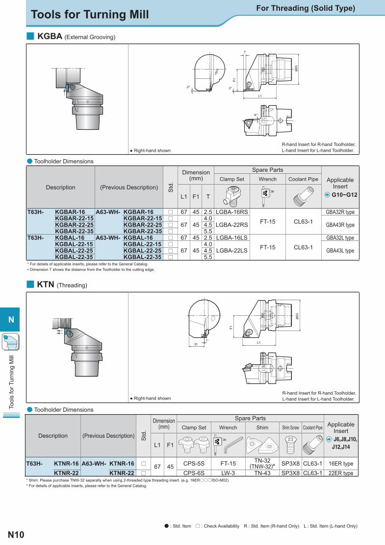
■ KGBA (External Grooving)
φ
● Right-hand shown
Description (Previous Description) Std
.Dimension
(mm)Spare Parts
Applicable Insert
G10~G12
Clamp Set Wrench Coolant Pipe
L1 F1 T
T63H- KGBAR-16 A63-WH- KGBAR-16 □ 67 45 2.5 LGBA-16RSFT-15 CL63-1
GBA32R typeKGBAR-22-15 KGBAR-22-15 □
67 454.0
LGBA-22RS GBA43R typeKGBAR-22-25 KGBAR-22-25 □ 4.5KGBAR-22-35 KGBAR-22-35 □ 5.5
T63H- KGBAL-16 A63-WH- KGBAL-16 □ 67 45 2.5 LGBA-16LSFT-15 CL63-1
GBA32L typeKGBAL-22-15 KGBAL-22-15 □
67 454.0
LGBA-22LS GBA43L typeKGBAL-22-25 KGBAL-22-25 □ 4.5KGBAL-22-35 KGBAL-22-35 □ 5.5
* For details of applicable inserts, please refer to the General Catalog. • Dimension T shows the distance from the Toolholder to the cutting edge.
● Toolholder Dimensions
R-hand Insert for R-hand Toolholder, L-hand Insert for L-hand Toolholder.
Description (Previous Description) Std
.
Dimension(mm)
Spare Parts Applicable
Insert J6,J8,J10,
J12,J14
Clamp Set Wrench Shim Shim Screw Coolant Pipe
L1 F1
T63H- KTNR-16 A63-WH- KTNR-16 □ 67 45 CPS-5S FT-15 TN-32(TNW-32)* SP3X8 CL63-1 16ER type
KTNR-22 KTNR-22 □ CPS-6S LW-3 TN-43 SP3X8 CL63-1 22ER type* Shim: Please purchase TNW-32 separatly when using 2-threaded type threading insert. (e.g. 16ER○○○ISO-M02) * For details of applicable inserts, please refer to the General Catalog.
● Toolholder Dimensions
■ KTN (Threading)φ
● Right-hand shownR-hand Insert for R-hand Toolholder, L-hand Insert for L-hand Toolholder.
Tools for Turning Mill For Threading (Solid Type)
● : Std. Item □ : Check Availability R : Std. Item (R-hand Only) L : Std. Item (L-hand Only)
N11
N
Tool
s fo
r Tur
ning
Mill
N 08 70T63 H
H Yes
No
Manual Clamp HoleN
C
For Boring Bar
For Drill
BL For Blank Tool
Toolholder
0810
ø8ø10
Internal Dia.
Length from Gauge Line
Toolholder Length
(mm)Interface Size
T63:HSK-T63T100:HSK-T100
Nocode
● Coolant Pipe • Coolant pipe is built into toolholder.
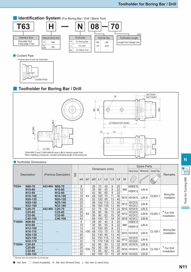
■ Toolholder for Boring Bar / Drill
■ Identifi cation System (For Boring Bar / Drill / Blank Tool)
Description (Previous Description) Std.
Dimension (mm)Spare Parts
RemarksClamp Screw Wrench Coolant Pipe
ød ød1 øD L1 L2 L3 L4 M
T63H- N08-70 A63-WH- N08-70 □ 8
63
28 70 45 9 20M8
HS8X10LW-4
CL63-1 Boring Bar Installation
N10-80 N10-80 □ 10 35 80 55 9 22 HS8X12N12-90 N12-90 □ 12 42 90 65 9 22N16-100 N16-100 □ 16 48 100 75 11 30 M10 HS10X16 LW-5N20-120 N20-120 □ 20 52 120 95 13 40N25-140 N25-140 □ 25 56 140 115 13 50 M12 HS12X16 LW-6N32-160 N32-160 □ 32 56 160 135 13 60 HS12X12
T63H- C20-75 A63-WH- C20-75 □ 2063
52 75 50 13 22 M10 HS10X16 LW-5CL63-1 * For Drill
InstallationC25-85 C25-85 □ 25 56 85 58 15 28 M12 HS12X16 LW-6C32-90 C32-90 □ 32 56 90 62 15 30 HS12X12C40-100 C40-100 □ 40 68 100 72 18 35 M16 HS16X12 LW-8
T100H- N08-80
-
□ 8
100
28 80 45 9 20M8
HS8X10LW-4
CL100-1 Boring Bar Installation
N10-90 □ 10 35 90 55 9 22 HS8X12N12-100 □ 12 42 100 65 9 22N16-110 □ 16 48 110 75 11 30 M10 HS10X16 LW-5N20-130 □ 20 52 130 95 13 40N25-150 □ 25 62 150 115 13 50 M12 HS12X18 LW-6N32-170 □ 32 72 170 135 13 60 HS12X20
T100H- C20-85-
□ 20100
52 85 50 13 22 M10 HS10X16 LW-5CL100-1 * For Drill
InstallationC25-90 □ 25 62 90 58 15 20 M16 HS16X18 LW-8C32-95 □ 32 72 95 62 15 20C40-105 □ 40 82 105 72 15 25 M16 HS16X20 LW-8
* Shorter than the toolholder for boring bar.
● Toolholder Dimensions
Coolant Pipe
Toolholder for Boring Bar / Drill
● : Std. Item □ : Check Availability R : Std. Item (R-hand Only) L : Std. Item (L-hand Only)
φd1
L1
L2(Attachment depth)
φD
φd
M26(T63H)29(T100H)
L2 (45)
φd
(φ8)
φ8.
4
T63H-N08-70 and T100H-N08-80 have a φ8.4 internal coolant hole. When installing a boring bar, consider protruding length of the boring bar.
L3 L4
N12
N
Tool
s fo
r Tur
ning
Mill
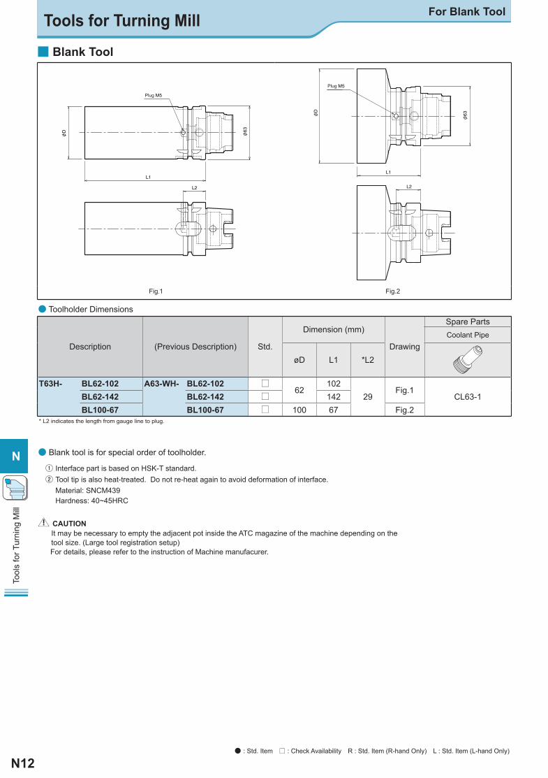
■ Blank Tool
Plug M5
φφ
Plug M5
φ
φ
Fig.1 Fig.2
Description (Previous Description) Std.
Dimension (mm)
Drawing
Spare Parts
Coolant Pipe
øD L1 *L2
T63H- BL62-102 A63-WH- BL62-102 U62
10229
Fig.1CL63-1BL62-142 BL62-142 U 142
BL100-67 BL100-67 U 100 67 Fig.2* L2 indicates the length from gauge line to plug.
● Toolholder Dimensions
● Blank tool is for special order of toolholder.
① Interface part is based on HSK-T standard. ② Tool tip is also heat-treated. Do not re-heat again to avoid deformation of interface.
Material: SNCM439Hardness: 40~45HRC
▲▲! CAUTION It may be necessary to empty the adjacent pot inside the ATC magazine of the machine depending on the tool size. (Large tool registration setup)For details, please refer to the instruction of Machine manufacurer.
Tools for Turning Mill For Blank Tool
● : Std. Item □ : Check Availability R : Std. Item (R-hand Only) L : Std. Item (L-hand Only)