Embed Size (px)
Citation preview
NISTIR 8093
Tools for Robotics in SME Workcells: Challenges and Approaches for
Calibration and Registration
Jeremy A. Marvel Elena Messina
Brian Antonishek Karl Van Wyk
Lisa Jean Fronczek
This publication is available free of charge from: http://dx.doi.org/10.6028/NIST.IR.8093
NISTIR 8093
Tools for Robotics in SME Workcells: Challenges and Approaches for
Calibration and Registration
Jeremy A. Marvel Elena Messina
Brian Antonishek Karl Van Wyk
Lisa Jean Fronczek
Intelligent Systems Division Engineering Laboratory
This publication is available free of charge from: http://dx.doi.org/10.6028/NIST.IR.8093
November 2015
U.S. Department of Commerce Penny Pritzker, Secretary
National Institute of Standards and Technology Willie May, Under Secretary of Commerce for Standards and Technology and Director
Disclaimer
Commercial equipment and materials are identified in order to adequately specify certainprocedures. In no case does such identification imply recommendation or endorsement bythe National Institute of Standards and Technology, nor does it imply that the materials orequipment identified are necessarily the best available for the purpose.
Abstract
An overview of the challenges associated with robot workcell calibration and registration ispresented, with a particular focus on the challenges faced by small- and medium-sized manufacturing enterprises (SMEs). Considerations for the barriers to integrating systems-of-systems workcells are described, and the proposed solutions from literature are presented. We discuss the impacts that calibration and registration have on many commonrobot applications, and highlight specific use cases of robot-sensor and robot-robot systemregistration.
i
TableofContents
Introduction ....................................................................................... 1
Background ........................................................................................ 3
Barriers to Ease of Adoption of Robotics.................................. 4 Locating the Part................................................................................................................................5 Grasping the Part ...............................................................................................................................6 Moving the Part ..................................................................................................................................6 Placing the Part within the Assembly .........................................................................................7 Manipulating (Reorienting or Repositioning) Parts..............................................................7 Fastening ..............................................................................................................................................8 Integrated System Considerations...............................................................................................8Transporting Materials ..................................................................................................................................9Offline Programming ......................................................................................................................................9Collaborative Robots....................................................................................................................................10
Calibration Requirements and Techniques...........................12 Camera Calibration ........................................................................................................................ 13 Robot Calibration ........................................................................................................................... 14 Articulated Robot Calibration ..................................................................................................................14 Robot-Camera Calibration.........................................................................................................................16 Robot Calibration using Calibrated Cameras ....................................................................................17Robot-Vehicle Calibration..........................................................................................................................18 Robot-Gripper/Hand Calibration ...........................................................................................................19Calibrating Robots to CAD Models for Offline Programming.....................................................20
Calibrating Virtual Models to Sensor Data............................................................................. 21Template Matching .......................................................................................................................................22Feature Matching...........................................................................................................................................22Cross-Modal Fitting ......................................................................................................................................23
Discussion .........................................................................................24
Bibliography.....................................................................................25
ii
1
Introduction
AnewvisionforU.S.manufacturingisemergingtostrengthenU.S.competitivenessintheface of global trends that are driving manufacturers towards dramatically greaterresponsiveness and innovation in their enterprises. This vision requires development offully-integrated, collaborativemanufacturing systemswhich respond in real time tomeetchanging demands and conditions in the factory, in the supply network, and in meetingcustomerneeds.Becauseoftheirinherentflexibilityandreusability,roboticsystemsareanessential part of achieving this vision. To succeed, robotic systems need to be highly-capable, perceptive, dexterous, mobile, and relocatable and be able to operate safely incollaborationwithhumansorotherrobots,easily taskedandre-tasked,andbe integratedinto the rest of the enterprise seamlessly and quickly; in otherwords, the robot systemsneed to be smart. The National Institute of Standards and Technology (NIST) iscontributing standards andmeasurement science1to enable dynamic production systemsand rapid design-to-product transformation, with an emphasis on assembly-centricmanufacturing.
Thesesmarterrobotswillbeableto(1)performassembly-centrictasksinless-structuredsurroundings by relying on distributed and sensor-derived information about theworkspaceratherthanonrigidfixturingofcomponents,(2)workcollaborativelywithotherrobotsandwithhumans,and(3)willbeabletonavigatearoundtheshopfloor,bringingthetoolsandfunctionalitytowheretheyareneeded.
InadditiontoexecutingaProgramthatseekstoprovidethemissingmeasurementsciencetoenableattainingthevisionandbenefitsofroboticsystemsforsmartmanufacturing,NISThas launched a project to specifically investigate the technical barriers that limit theadoption of robotic systems by small and medium enterprises (SMEs). Installing andmaintainingroboticsystemsischallengingandwillbecomemoresoastherobotsbecomemore sophisticated. The calibration of robots and registration of multiple sensors, inparticular, requires expertise and equipment that many small- and medium-sizedmanufacturerstypicallymaynothave.
Calibration refers to the process of measuring the characteristics and performance of asystem, developing a mathematical model of the system from those measurements, andthenverifyingandvalidatingthemodel’saccuracyinrepresentingthesystem.Thismodelisthenusedtoevaluateandtunetheperformanceandbehaviorofthesystemthroughthecontinuous assessment of the errors between the ideal (model) and actual performance.Forroboticsystems,thesemodelscapturethekinematicanddynamiccharacteristicsofthephysical robot. These models are then verified through detailed measurements, and asubset of parameterized controls that represent the robot’s behaviors are selected andintegratedintothemotioncontrolloop.
Forrobotusers,calibrationisessentialforreapingthefulladvantagesfromroboticsystems.
1Measurement Science includes development of performance metrics, measurement and testing methods,predictive modeling and simulation tools, knowledge modeling, protocols, technical data, and referencematerials and artifacts; Evaluation of technologies, systems, and practices, including uncertainty analysis;Development of the technical basis for standards, codes, and practices—in many instances via testbeds,consortia, standards and codes development organizations, and/or other partnerships with industry andacademia;andConductofinter-comparisonstudiesandcalibrations
2
Calibration enhances robot positioning accuracy, enables vision systems to accuratelyreport object identification and localization information, and ensures that force sensorswithin the robotic systemknow thedifferencebetweena slight tapon itshumanpartnerandanimpactthatcouldresultininjury.Calibrationproceduresallowusersto“retune”therobotbacktoitsoriginal,stockconfigurationevenasthesystemagesthroughmechanicalwear, dimensional drifts due to environmental changes, and even through componentreplacements. Referring to the robot arm, “calibration errors can be classified in fivecategories: environmental (such as those caused by temperature drifts), parametric (forexample,manufacturingandassemblyerrors),measurement(causedbylimitedresolutionof the motor encoders), computational (computer round-off, and steady state controlerrors),andapplication(suchasinstallationerrors)”[1].Similarcategoriesoferrorsexistfor sensors: environmental (e.g., lighting), parametric (such as lens distortion due tomanufacturingerrors),measurement(causedbylimitedresolutionofthesensororlimitedfrequency of data capture), computational (e.g., algorithmic limitations, round-off), andapplication(e.g.,reflectivityandotherpropertiesoftheparts;fieldofviewbeingoffsetbybeingbumped).Another term related to calibration that is frequently used with respect to robots is“registration.” Registration refers to theprocessofmeasuringandmapping the feedbackfrom one system to the model of another, correcting for differences in resolution, scale,direction, and timing. Such feedback includes, but is not limited to, position data,coordinate framedata, rawsensordata,andcomplexworldmodels. Forroboticsystems,suchregistrationincludesmappingsensoroutputssuchasimagesortorquemeasurementstothekinematicanddynamicprofilesoftherobot,andviceversa.Inmulti-robotsystems,registrationalsoreferstomappingthecoordinateframesandmotioncharacteristicsoftherobotstooneanother.Withoutproperperiodiccalibration,roboticsystemswillnotperformadequately,causingfailuresandexpensivedowntime.Inadditiontogivingtheuserfaiththattherobotwillgotoitsassignedpositionwhenrequested,awell-qualifiedroboticsystem(inotherwords,acalibratedone)enablesusers to implementoff-lineprogrammingand simulation. Withawell-calibrated robotic system, users can avoid costly mistakes by testing out the robotprogrampriortoimplementationoftheprogramontheshopfloorandinbeingabletoplanoutthenextprogramofflinewhiletherobotisstillinusewiththefirsttask.The competitive advantages that smart robot systemspromise aremostlyoutof reachofmost small and medium enterprises until the barriers to adopting robotic systems arereducedsignificantly. Of course, largermanufacturerswill alsobenefit fromreducing thetechnicalbarriersforinstallingandmaintainrobotsystems.Calibrationisonesuchmajortechnicalbarrier.Thisreportprovidesahigh-leveloverviewofthevariouscalibration-relatedchallengesthatcurrently exist and are expected tomultiplywithmore advanced robots that aremobile,sensor-laden,andrequiredtoworksafely incollaborationwithotherrobotsandhumans.In the following sections, we will briefly discuss the importance of calibration andregistrationinsensor-drivenrobotapplications,andtheapplicationchallengesfacedbyallscalesofmanufacturers.Wealsoprovideahigh-leveloverviewofvarioustechniquesusedtocalibrateandregisterrobots,sensors,andvirtualmodels.Weconcludewithadiscussionregarding how toolkits for reducing the burden of calibrating and registering workcellelementswillenableabroaderadoptionofrobotsystemsinmanufacturingapplications.
3
Background
Robotsystemshavealteredthefaceofmanufacturingonmanyfronts.Theyhaveincreasedquality and throughput through their superhuman repeatability and speed. Theseadvantagesfollowlengthyandexpensiveup-frontpreparations.One of the most pressing issues identified at a workshop exploring Opportunities inRobotics,Automation,andComputerScienceheldattheWhiteHouseConferenceCenterin2013[2]wasrelatedtothecostofdeployingandmanagingaproductionline:“Accordingtothe[InternationalFederationofRobotics]IFRWorldRobotics2009thecostofdeployinganautomation system canbe split into20% to25% for the robot, 20% to30%auxiliaryhardware,and45%to60%systemsintegration.Thisfractionappearstohavenotchangedsignificantlyoverthelastfouryears.Thecostofsystemsintegrationissignificantandthereis very limited reuse of software from one application to the next. In addition, the timerequired to deploy a line can be significant.” A significant investment in effort andintellectual capital is required to integrate robots and sensors into the manufacturingworkflow. These systems must be both individually and collectively calibrated andregisteredtogether.Calibrationandregistrationerrorsanduncertaintiesmustbeidentifiedandmeasured,andcompensationsfortheseerrorsanduncertaintiesmustbeputintoeffect.These stepsmust be taken periodically as robots and sensors age, ormore frequently asprocess flows change, product lines evolve, new manufacturing uncertainties areintroduced (e.g., as a newbatch of components is delivered from an external vendor), orequipmentandtoolsarereplaced.Suchaninvestmentisparticularlychallengingtosmall-andmedium-sizedenterprises,whosebusinessmodelsaremorelikelytoinvolvecustomorone-offmanufacturingofproducts[3]. ThereportfromtheOpportunitiesWorkshopgoeson to note that the European Union is starting a program to counter this hindrance toroboticsadoption,especiallybySMEs:The“factoryinaday”project[4,5]aimstodeveloptechnologies and tools that reduce the installation and startup time. Among the areashighlighted as being essential to achieve this is auto-calibration by the robots and theirsensors.TheIFRfigurequotedintheOpportunitiesWorkshopreportcorrelatestootherestimates,suchasthatthecostofinstallationandsupportinginfrastructureinacellisnormallyuptoten times the costof the robot [6]. Another significant statistic is that45%of the robotsupplyistakenupby10%oftheindustry,primarilybycompaniesthathavemorethan500employees(mostlyautomotive)[7],andthat90%ofthepotentialusershavenotadoptedrobotics formanufacturing [8]. Given that it is estimated that 98%of allmanufacturingenterprises are considered small- or medium-sized, it is clear that SMEs represent theprincipaldemographicthatcanbenefitfromautomation.Evenifthesituationhasimprovedsignificantly since these figures were estimated, it is unlikely that the installation andinfrastructurecostshavedroppedsufficientlytofosterdramaticallygreaterpenetrationbyrobots,especiallyinsmalltomediumenterprises.ManyexpertsbelievethatSMEsholdthefuture of U.S. manufacturing. However, SMEs are the least likely to adopt the newesttechnologiesduetolimitedcapitalinvestmentfunds,engineeringstaff,andlimitedproofofperformanceofthetechnologiesthemselves.In the subsequent sections,wewill examine the contributors to these disproportionatelylargeinstallationandmaintenancecoststhatdissuadegreateruseofrobotsystems.
4
BarrierstoEaseofAdoptionofRobotics
Thedomainofindustrialrobotsuseandintegrationhasbeendominatedbythelarge-scaleautomotive and electronics industries [9]. These industries fall into the “large volume”(with high productmix, and/or short product life) [2]. Although recent trends show anexpansion of robot adoption outside of these areas, progression into these new fields isslow.Asmentioned previously, sources cite the cost of integration as being a key factor in thehesitancy for introducing robotics into production lines that currently see little to noautomation. Cost alone, however, cannot account for this limited adoption of roboticsoutsideoftheautomotiveandelectronicsdomains.Manyindustrialrobotscurrentlyonthemarket are clearly intended for targeted applications within these two domains.Application-specific packages anddesign features have limiteduse outside of these nicheuses. Recent market trends, however, witness new designs of robots emerging in themarket that are more general purpose, and focus on human-robot collaboration andmodularityratherthansinglepurposetaskperformance.Althoughthesenewrobotdesignsarecorrelatedwiththegrowingexpansionofrobotsoutsideofautomotiveandaerospacemanufacturing,anyformofcausalityisnotevident.Thesenewrobotdesigns andapplicationsposean interesting challenge. Trends indicatethattheyarebecomingincreasinglyeasiertouse,butultimatelymoredifficulttointegrateduetothesacrificesincurredbyeffortstoreducecostandbroadenapplicationscope.Somecollaborative robot designs, for instance, sacrifice accuracy and repeatability in favor ofinherentsafety,whichimpactstherobots’reliabilityontheproductionfloor.Otherdesignstout flexibility andmodularity of design of components, but suffer in terms of optimizedpath planning and compromised structural rigidity due to the open-ended nature of therobots’ designs. Clearly,mechanisms for providing calibration and registration in a clearandaccessiblemannerwouldbenefitthesenewrobottechnologies,andeasetheprocessofadoptionintonewmarkets.ItisalsoevidentthatthebroadfieldofmanufacturingroboticsistoovastforNIST’sRoboticSystemsforSmartManufacturing(RSSM)programtotackleallatonce.Instead,weneedtofocus on a specific, example domain that represents a significant area for growth acrossmultiplemarkets.AsmanufacturersarelookingtowardsautomationingeneralaspartofastrategytohelpreshoreorretainjobshereintheUnitedStates(US),theyareconsideringautomation in their assembly tasks. While the automotive industry is the predominantindustry forassembly,other industries suchasdurablegoods (e.g.,householdappliances,lawn equipment), electronics, and medical devices industries are increasing their pushtowardsusingroboticassemblyintheirmanufacturingprocess.NISThasidentifiedroboticassembly in its SmartManufacturingportfolio as being an exemplardomain that impactsmultipleindustriesatallscales. Itthusfollowsthatweusethisapplicationasourguidinginspiration for identifying approaches for calibration and registration. The calibrationchallenges posed by the assembly application are expected to generalize to many otherroboticapplications.
5
WebeginourdiscussionwithadefinitionofassemblyfromWhitney[10]:
“An assembly is a chain of coordinate frames on parts designed to achievecertain dimensional relationships, called key characteristics, between someofthepartsorbetweenfeaturesonthoseparts.”
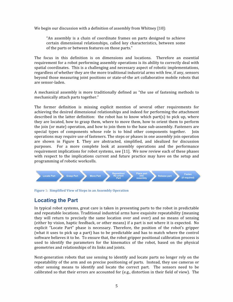
The focus in this definition is on dimensions and locations. Therefore an essentialrequirementforarobotperformingassemblyoperationsisitsabilitytocorrectlydealwithspatialcoordinates.Thisisachallengingandnecessaryaspectofroboticimplementations,regardlessofwhethertheyarethemoretraditionalindustrialarmswithfew,ifany,sensorsbeyondthosemeasuringjointpositionsorstate-of-theartcollaborativemobilerobotsthataresensor-laden.Amechanical assembly ismore traditionally defined as “the use of fasteningmethods tomechanicallyattachpartstogether.”The former definition is missing explicit mention of several other requirements forachievingthedesireddimensionalrelationshipsandindeedforperformingtheattachmentdescribed in the latterdefinition: the robothas toknowwhichpart(s) topickup,wheretheyarelocated,howtograspthem,wheretomovethem,howtoorientthemtoperformthejoin(ormate)operation,andhowtojointhemtothebasesub-assembly.Fastenersarespecial types of components whose role is to bind other components together. Joinoperationsmayrequireuseoffasteners.Thestepsorphasesinoneassemblyjoinoperationare shown in Figure 1. They are abstracted, simplified, and idealized for discussionpurposes. For a more complete look at assembly operations and the performancerequirementimplicationsforrobotsystems,see[11].Wenowrevieweachofthesephaseswith respect to the implications current and future practice may have on the setup andprogrammingofroboticworkcells.
Figure1:SimplifiedViewofStepsinanAssemblyOperation
Locating the Part Intypicalrobotsystems,greatcareistakeninpresentingpartstotherobotinpredictableandrepeatablelocations.Traditionalindustrialarmshaveexquisiterepeatability(meaningthey will return to precisely the same location over and over) and nomeans of sensing(eitherbyvision,hapticfeedback,orothermeans)ifapartisnotwhereitisexpected.Noexplicit “Locate Part” phase is necessary. Therefore, the position of the robot’s gripper(what ituses topickupapart)has tobepredictableandhas tomatchwhere thecontrolsoftwarebelievesittobe.Toensurethat,therobotgripperpositionalcalibrationprocessisused to identify the parameters for the kinematics of the robot, based on the physicalgeometriesandrelationshipsofitslinksandjoints.Next-generationrobots thatusesensing to identifyand locatepartsno longerrelyon therepeatabilityof thearmandonprecisepositioningofparts. Instead, theyusecamerasorother sensing means to identify and locate the correct part. The sensors need to becalibratedsothattheirerrorsareaccountedfor(e.g.,distortionintheirfieldofview).The
Locate Part Grasp Part Move Part Reposition/Re-orient
Part
Place part into
assembly Release part
Fasten (if required)
6
sensor’s frameof referencemustbe registeredwith that of the robot such that the robotknowsthelocationofthepart.Iftherearemultiplesensors,theymayneedtoberegisteredwitheachothers’ framesof reference. To thisend, it is important todistinguishbetweenthesensor’scalibrationand therobot’scalibration. Subsequentsectionswilldiscusshowcameracalibrationmaybeusedtohelpachieverobotcalibration.
Grasping the Part Intraditionalroboticworkcells,asdiscussedintheprevioussection,theparttobegraspedis assumed to be in a known pre-determined position. The end-of-arm tooling is oftencustomized to be able to pick up the part. Indeed, the robot may need to change outgrippers for differentpartswithin the sameassembly. The robot’s calibrationprocedurehastotakeintoaccountthetoolcenterpoint(TCP),whichisakeypositiononthegripper,often the center between the two jaws since this is usually the point whose position iscontrolledduringthearm’smotion. Therefore,therewillneedtobemultipleTCPsstoredwiththerobot’scontrolleriftherearemultiplegrippers/endeffectors.Grippersthathavemultipleopeningpositionswillneedtobecalibratedtoensurethatthe100%open,50%open,etc.areatthecorrectaperture.Asmore general-purpose end effectors enter themarketplace, there are some additionalsensor modalities that are becoming readily available. Embedded proximity sensorsprovideconfirmationthatapartiswithinthegripper.Somegrippershaveforcefeedback,whichrequirescalibrationtoavoidexertingtoomuchforce(anddamagingthepart)ortoolittle(andnothavingasecureholdonit).Asbio-inspiredrobotichandswithatleastthreefingers, very high degrees-of-freedom, and tactile sensing emerge, the calibrationrequirements and complexities increase. Each finger has to be calibrated for force andposition. Specialized sensors, such as for shear force, vibration, and temperature, whichassistthetactileresponsivenessofthehand,alsorequirecalibrations.
Moving the Part Duringassembly,arobot’smotionsmaybecoarselyclassifiedaseithergrossor fine. Wewillcovergrossmotionsinthissection.Finemotionssegueintoinsertion,whichiscoveredin the next section. Gross motions are used to bring a part to its destination assemblylocationandoccuroverdistancesthatare largecomparedtothepartbeingmoved. Theytend to be as fast as possible and do not require high accuracy, hence, relatively largetrajectoryerrorsareallowable.Fortraditionalroboticarmsthatdonothavesensorstodetectobstaclesorpartlocations,themovementswillbeperformed“blindly”sincetheyassumethatconditionsarecontrolledin their surroundings so their path will be obstacle-free. The TCP will follow theprogrammedpath,assumingthattherobotarmandendeffectorarecorrectlycalibrated.Anextgenerationrobotmayrelyonsensorstoensuremovementsdonotcausecollisionswithobstacles.Collaborativerobotsmayhaveembeddedsensingthatdetectsthepresenceand/or contact with an object and causes the arm to stop or “give way” to the object.Obstacle detection sensors require calibration and registration for the system to planobstruction-freemotionpaths. Contactor forcesensingforcollaborativerobotswillneedcalibrationaswell.
7
Placing the Part within the Assembly Finemotionsareusedforthefinalapproachtowardsthematingphaseandforthematingtask itself. Finemotions are smallwith respect to thepart size andmayoccurwhen theparts are in contact. Errors in position and orientation in this phase are usually smallenoughthattheyaredetectedonlybyforcesensors.Incurrentpractice,passivemechanicaldevices,suchasaremotecentercompliance,maybeused to aid the finalmotion if insertion is involved. Some robotsmay have active forcesensingavailablemountedonthefaceplatepriortotheendeffectorandifso,boththeforcesensinganditseffectontherobot’smotionshavetoundergocalibration.The force sensing options are expanding for future implementations. Robotic handswillsense forces in thenormalaswellas the tangentialdirection. Thesemulti-modalsensingsystems have to be calibrated and registered together. Fine positioning, which includesbeing able tomaintain small angular resolutions, places exacting demands on calibrationandregistrationofthepositioningandsensingsystemswithinthehandandthearm.
Manipulating (Reorienting or Repositioning) Parts In current implementations, the ability of robots to reposition parts once they haveacquiredthemisfairlylimited.[12]Partsmayhavetobeplacedinanintermediatefixturetoallowtherobotstograsptheminadifferentorientationpriortoplacingthepartwithintheassembly. Theprincipal calibrationneed therefore is for thearm’sandendeffector’sposition.Dexterousmanipulation is an active area of research and promises robotic systemswithgreaterflexibility. Theabilityofhumanstomanipulateawiderangeofobjectswithgreatdexterity and precision enables them to operate productively in the world. People canassemble, disassemble, and determine many part properties through touch. This iscurrently beyond the capabilities of even the most sophisticated robots, and is a majorobstacletomovingrobotsintosmallandmedium-sizeenterprises.One of the essential capabilities needed to address the challenges in next-generationautomation is believed to be robots that are equippedwith dexterousmanipulators [13].Dexterousmanipulation is an areaof robotics inwhichmultiplemanipulators, or fingers,cooperate to grasp and manipulate objects [14]. While the definition emphasizes the“fingers”,(i.e.,theendeffector),whole-armdexteritymayberequiredincertainoperations,suchaswhentherobotistoaccessconfinedorhard-to-reachlocationsonaworkpiece.Thedefinitionreflectsthatmanyreferencestodexterousmanipulationimplybio-inspired,moregeneral-purposerobotichands,ratherthanthearmitself.Dexterousmanipulationrequirestheusertoconsidertheobjecttobemanipulatedintermsofforce(s)ontheobjectandwhatmovementsareneeded.Participantsinthe2013DexterousManipulationforManufacturingApplicationsWorkshop[15]identifiedseveralkeychallenges,mostofwhichapplytothefuturevisionforassemblyroboticsystems:
1. Makingiteasiertotrainrobotsinchallenginganddynamicenvironments;2. Developing a general-purpose end of the arm device that is able to grasp and
manipulateawiderangeofpartsreliablyinanyorientation;3. Arobotbeingmore “human-like” in its capabilities to graspandmanipulateparts
8
basedonpastlearnedknowledge;4. The ability to use tactile sensors (i.e., force/pressure, shear, temperature, and
vibration)thatprovidetherobotasenseoftouch;5. Robotics systems having the flexibility to support large-scale manufacturing
productsaswellasdetailedsmall-scaleones;6. Robotic systems attaining the ability to work in confined spaces (and possibly
hazardousenvironments)withclosetolerances.Futurerobotsystemswillbeabletoperformin-handmanipulationtore-orientpartspriortoinsertionorjoinoperationsandbeabletodexterouslyaccessdifficult-to-reachassemblygeometries. Thisabilitywillbehighlydependentonmulti-fingermechanicaldesigns thatarerichinsensorcues,includingnormalandtangentialforces,vibration,andthermalflux.Thearm itselfmayrequireanarrayof forceor tactile sensors. Therefore, thecalibrationandregistrationrequirements for thisbreedofdexterousmanipulators(armsandhands)willberigorousanddemanding.
Fastening Assemblies use a wide range of fastening methods. Methods range from snap or pressfitting, to use of ancillary components such aswashers, pins, screws, nuts, and rivets, toprocesses such as soldering, welding, or gluing. Robotic implementations today rely onspecialized end effectors and precise positioning for fastening operations. These includedrill and screw spindles or multi-function end effectors that house drills, screwdriverspindles, rivet guns, glue dispensers, and other tools in various combinations. Positionalaccuracyisparamountforplacementofendeffectorssuchasdrills. Insomeapplications,suchasforaircraftassemblies,accuraciesontheorderof0.25mmorbetterarerequired.[16] For certain tools, particularly those that are rotational, orientation accuracy is alsoessential.[17]Fortighteningfasteners,forcesensingmaybeincorporatedinthespecializedend effectors. Some current implementations use vision to more precisely locate thefastening position, e.g., a hole or a bolt ontowhich to place awasher or nut. Again, thecoordinate frame of the vision system must be well-calibrated with that of the robot’sposition. Some advocate re-calibrating very frequently, in case the camera gets bumpedbetweenoperations.[18]As robotic systems become more widely deployed for assembly operations, the use ofspecialized fasteningend-of-arm toolingwill continue. Thesensitivityandadaptabilityofthesetoolswill increase. Furthermore,theirsensingwillbefusedwiththatoftherobot’sarmtoprovideunifiedfeedbackonposition,torque,forces,andothercriteriaforeffectiveand efficient fastening. Therefore, sensors embedded in specialized tools (drills,screwdrivers, riveters, etc.) will need calibration with those on the arm (which couldincludecamerasforpositiondeterminationaswellasforceandtorque,vibration,etc.).
Integrated System Considerations Beyond the basic principles of material handling in single-robot workcells, integratingrobotsintolargermanufacturingchainspresentsadditionalchallengesrequiringcalibrationandregistration. Suchchallengesarecenteredonthecoordinationofmultipleautomatedsystems, includingroboticvehicles,conveyorandfeedingsystems,monitoringsystems,aswellasotherrobotsandevenhumanoperators.
9
TransportingMaterials
Automated or automatic guided vehicles (AGVs) are mobile robots used in industrialapplications to transport materials in a manufacturing facility or warehouse. Currentmodelstypicallyusemarkersintheenvironment(embeddedinthefloor,ceilings,orwalls)to guide their paths. Some AGV models have on-board sensing, particularly to detecthumansorobjectsintheirpathsandhalttheirmotion.Dependingonthetypeofguidanceapproach used by the AGV, therewill be differing calibration requirements. Examples ofguidance technologies include magnetic, inductive, retro-reflective, and visual fiducialmarkers.Forthesimplestguidanceapproach,whichhasthevehiclefollowembeddedpathsinthefloor,forexample,thereisminimalcalibration/registrationrequired.However,ifthevehicle’s navigation relies on reference markers in the environment (possibly inconjunction with its own internal position estimate based on dead reckoning or othertechnique), then a lengthy calibration process is necessary upon installation. Should theenvironmental conditions change (some markers may become covered by equipment orbumped,thepathsareextendedintonewareas,etc.),recalibrationmaybeneededaswell.Calibrationsmustbeperformedforanyadditionalonboardsensors,particularly for thosefor safety. Ifmultiple sensors are to be used to detect or confirm an obstacle, then theymustbe registered together to ensure that theirdifferentperspectivesmap to a commoncoordinateframe.Future mobility advances in sensing and planning will enable AGVs to have greaterautonomyandflexibility.Theywillhaveagreatervarietyofonboardsensorsforsafety,forlocalizing themselves, and for planning and adapting paths around obstacles. Safe andeffectiveusewillrequireverificationandvalidationthatthemobileplatform’spositionandvelocity sensors are calibrated and registered together, especially for safety reasons.Furthermore,mobilemanipulators (articulated robot armsmounted onmobile platforms[19])areanticipatedasbeingcriticaltechnologiesforagilemanufacturingapplications,andultimatelyposethegreatestuncertaintyandriskinhuman-occupiedfactoryenvironments.Hence,mobilemanipulatorswillposesignificantdemandsonensuringthatallcomponentsarecalibratedandregistered.
OfflineProgramming
Duetothetimeandexpenserequiredtobringanewroboticworkcellonline,endusersandintegrators prefer to design and program a workcell in a computer-aided design (CAD)system prior to even beginning workcell construction (e.g., [17, 20, 21]). This is calledoffline programming and provides the opportunity to reduce the programming time andimproveproductivity.Neto,Pires,andMoreira [21]note thatagoodofflineprogrammingtool is an important tool forSMEswhodonothavepersonnel trained tooperate robots.However,theCADlayoutoftheworkcell–aswellasthemodelsoftherobot(s)–representidealized versions of the system as a whole, and minor uncertainties and measurementimperfectionscausetherealandvirtualworkcellsandrobotmotionstobemisaligned.In current practice, considerablepost-construction effortmaybe required to compensateforthesetranslationalerrorspriortodeployinginthephysicalworld[22,23].Oneexamplenoted thatproductivity improvedsignificantlywhencombiningofflineprogrammingwitheffectiveandefficientcalibration:bothproductiondowntimeandcosttoprogramtherobotweredecreasedby73%aftertheyreducedtheneedforextensive“touchup”[24].Thefuturewillbringgreaterdepthandbreadthinthesimulationcapabilitiesthatsupport
10
off-lineprogramming. Currentsimulationsystemsdonot typicallyhaveveryhigh-fidelitysensormodels,forexample.Modelingtheuncertaintiesandrealisticresponsesofasensorto different surface textures, geometries, and ambient conditions will be essential fordesigningandprogrammingsensor-richroboticworkcellsoffline.Similarly,tactilesensorsand hand kinematics must be well-modeled and well-calibrated to their physicalcounterparts. Hence, leveraging the advanced capabilities of next-generation roboticsystems through offline programming raises the importance of accurate calibrations of arobot’sarmkinematics,sensors,andadvancedhands.
CollaborativeRobots
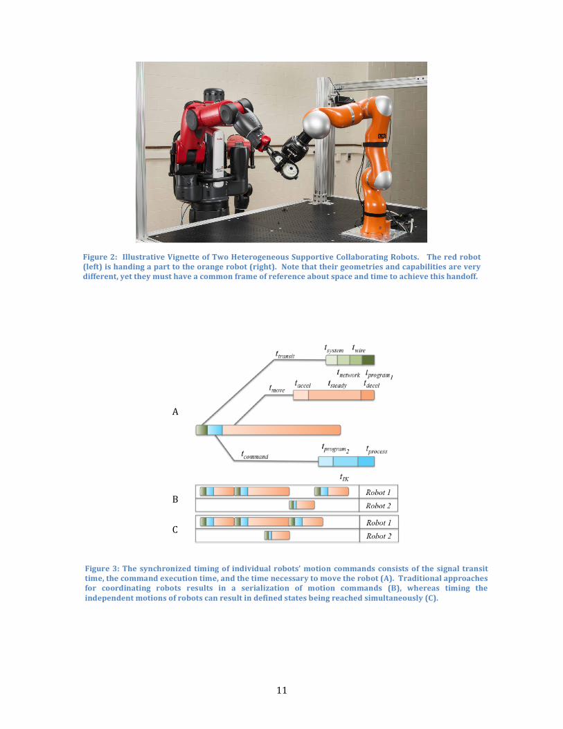
Robot collaboration (eitherwith humans orwith other robots) is often characterized byfourlevelsofinteraction[25]:independent,synchronous,simultaneous,andsupportive.Inindependent collaboration, the robotand its collaboratoroperateonseparateworkpieceswithout any interaction. In synchronous collaboration, the robot and its collaboratoroperateonsequentialcomponentsonthesameworkpiece. Insimultaneouscollaboration,the robot and its collaborator are co-located, and operate on separate tasks on the sameworkpiece(s) at the same time. And in supportive collaboration, the robot and itscollaborator work ‘cooperatively’ to complete the processing of a single workpiece.Simultaneous and supportive tasks are expected to have the highest potential for risk ofinjury[26],somoststate-of-the-art industrialoperationsrequiringrobotcollaborationdoso using synchronous interactions. In assembly tasks, for instance, multi-robot systemsperform the componentmanipulations in a series of workstation operations rather thansimultaneouslytoreduceriskstotherobots,parts,andhumansintheworkenvironment.Specifically,onerobotwillperformitsprogrammedtaskonthesharedworkpiece,andthenthat workpiece is passed to the next station for additional processing. Each robot isassignedasingletaskrole,andpartsarepresentedinfixtures.Whenmultiplerobotsmustoperatesimultaneously,theschedulingofthesystemistheprincipalconcernforintegrators[27].Suchschedulingincludesresourceallocations[28-30],processdistribution[29-32],logisticalcontrols(i.e.,partpresentations[28,33]),andcollisionavoidance[33].Inmanyofthesetestcases,thephysicalinteractionbetweenrobotsisrestrictedornonexistent,andtherobotsoperatesimultaneouslyinthesharedworkcell,butinanon-supportivemanner.Supportivecollaborationsrequirethethree-dimensionallocationandtime-basedcoordinationandsynchronizationofmotionstominimizepositioningandtrajectoryerrors.Sucherrorsmaynegativelyimpacttherobotsthemselves,damagepartsortooling,orpresenthazardstohumanoperatorsworkinginthearea.Figure2showsanexampleofdifferentrobotscollaborating.Whenprogrammingrobotsinheterogeneousconfigurations(i.e.,whentherobotshaveseparate,incompatiblecontrollers),therobots’joint-andCartesian-spacemotions,dataaccess,communication,andprocessingdelays,andsystemprocessingtimingsmustbecharacterizedandregisteredtoenablesynchronization(seeFigure2andFigure3).
11
Figure2: IllustrativeVignetteofTwoHeterogeneousSupportiveCollaboratingRobots. Theredrobot(left)ishandingaparttotheorangerobot(right).Notethattheirgeometriesandcapabilitiesareverydifferent,yettheymusthaveacommonframeofreferenceaboutspaceandtimetoachievethishandoff.
A
B
C
Figure3:The synchronized timingof individualrobots’motion commands consistsof the signal transittime,thecommandexecutiontime,andthetimenecessarytomovetherobot(A).Traditionalapproachesfor coordinating robots results in a serialization of motion commands (B), whereas timing theindependentmotionsofrobotscanresultindefinedstatesbeingreachedsimultaneously(C).
12
CalibrationRequirementsandTechniques
Thefieldofrobotandsensorcalibrationisbothvastandlong-lived,andassuchwecannotprovideanexhaustivesurveyofallpossiblecalibrationtechniques.Instead,wewillattemptto give a broad overview of many of the more commonmechanisms for calibrating andregisteringrobotsandsensors,bothasstand-aloneplatformsandasintegratedsystems.Ingeneral,acalibrationprocessconsistsoffoursequentialsteps:
1. Choosingamathematicmodel2. Takinglotsofmeasurementdata(thisstepimpliesadecisiononthemeasurement
device)3. Calculatingtheappropriatecontrolparametererrorstobeminimized,andfinally4. Integratingtheerrorcompensationintothesystem.
Calibrationscanbetime-consumingandcanbeperformedatvariouslevelsofcomplexity.Generalchallengesinclude:
• Determining whichmeasurements to take (location and number) to ensure goodresultswhileminimizingresourcesrequired
• Decidingwhichmetrology system ormeasurement approach to use for collectingthedata
• Decidingwhichalgorithmandtoolstouseforprocessingthedata,and• Knowingwhenthesystemisoutofcalibration.
For example, for robot arm kinematics, depending on the type of error modeled, thecalibration can be classified as Level-1 (only joints are modeled to determine therelationship between the signal to the joint and its actual joint displacement), Level-2(entirekinematiccalibrations–determinethebasickinematicgeometryoftherobotaswellas the correct joint-angle relationship), and Level-3 (non-kinematic calibrations whereerrors in positioning of the end effector are due to non-geometric errors such as jointcompliance, friction, and clearance, link compliance, stiffness, temperature, and dynamicmodelingcouldbeinthisleveltoo)[1,34].
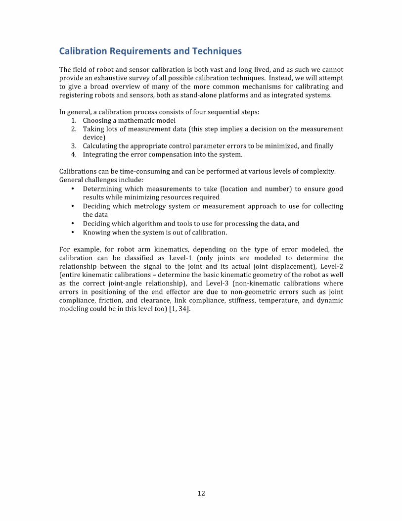
13
Figure 4 is a highly abstracted and idealized representation of a robot workcell with anarticulatedarmonamobilebase. Thearmhasamulti-fingeredhandwithtactilesensorsand the cell includes two external sensors. To function correctly, all the differentcomponents must be calibrated and many must have the relationships between theircoordinateframesestablished(“registered”).Inthenextsections,wewillprovideabriefsummaryofthecalibrationpracticesandissuesforthemaincomponentsinFigure4.
Camera Calibration Computer vision techniques precisely calculate andmathematically represent a camera’svarious property values -- both intrinsic and extrinsic. The extrinsic parameters defineexactlywhere in the3Dspace thatacamera is located in thephysicalworld(translation)andwhichwaythatthecameralensispointing(rotation). The intrinsicparameterscoverthecameramodel-specificattributessuchasthecamera’sfocal length, lensdistortion,etc.[35]. Knowing theseproperties then letsusdeterminehow the camera’s reported imagepixelvaluescorrespondtotherealworld(three-dimensional,3D,space)thatitisobserving.Theentireprocessposesmanydifficulties.Asdescribedin[36]:
Figure 4: Conceptual View of the Different Coordinate Frames and Calibration/RegistrationRequirements
14
“Complex robots can also pose many challenges for the calibrationprocedure. The robotmay havemany different sensors, and each sensoroften has very different error characteristics. For instance, a laserrangefinderdetectspointsin3Dverydifferentlythanastereocamera,andacamera’sprecisioninresolvingpointsisverydependentonitsfocallength.To complicate things further, if the camera ismounted on a robot arm orotheractuatedlinkage,thenthelinkage’serrorcharacteristicsmustalsobeincorporatedintothesensor’suncertainties.”
Oncethesepropertyvalueshavebeencalculated,thecorrespondencebetweenthecamera’simageview(i.e.,twodimensional–2D–imagespace)andtherealworld(i.e.,3DCartesianspace)positioncanbemathematicallyrepresented.
Robot Calibration AsuccinctsummaryofrobotcalibrationcomesfromRothetal.[37]:
“Calibration involves identifying a more accurate functional relationshipbetweenthejointtransducerreadingsandtheactualworkspacepositionoftheendeffectorandusing these identifiedchanges topermanentlychange(betweeneachconsecutivecalibration)therobotpositioningsoftware.”
Beforearobotcanplanatrajectoryorperformanykindofmotion,itmustfirstunderstandits own configuration. Encoder or resolver information is meaningless unless there is areference frame againstwhich all subsequent readings can be compared. Thismasteringprocessinvolvesmanuallymovingtherobotintoanaprioriestablishedconfiguration,andrecording the sensor readings. This is a registration process, where the robot’sjoint/encoderreadingsaremappedtoaknownposeoftherobot.Thisinformationisthenused to establish a kinematic mapping of the totality of the joint values to a Cartesiancoordinateframeattherobot’sorigin.At this point, assuming the mastering process was performed correctly, the robot iscalibratedonlyto itself. However,therobot isotherwisefullyfunctional inthatCartesianmotionstotherobot’stoolflangecanbecommandedrelativetothatbaseframe.Programscan be written and executed without issue provided that the robot does not have tocoordinate with another system (such as external sensors or other robots), or performactions using an attached tool. Such actions require quality calibration of the robot, andthenregisteringtherobottoanexternalcoordinateframe.
ArticulatedRobotCalibration
Ultimately,a robotmustbepreciselyawareof itsownposition,and thepositionofall itsconstituentcomponents,withinitsoperatingvolume.Thisisthecruxofrobotcalibration.A robot’s exact position, and its components’ positions, can be affected by amultitude offactors includingmachine wear, joint friction, andmanufacturing imperfections [38, 39].Robot calibration uses a combination of techniques to help compensate for any or all ofthese factors. That is, given a perfect robot calibration, a robot’s end effector will bepositionedinCartesianspacewithhighaccuracyandrepeatability.Thecurrenttechniquestoachieverobotcalibrationinvolveproceduressuchas
• Usingprecisionmeasurementtechniquestoobservethedifferencesbetweenactual
15
robotpositionand theposition the robot calculates it is at toobserve repeatableand/orpredictabletranslationandrotationerrors,and
• Modeling the capabilities of the robot in software and factoring in any knownobservableerrors.
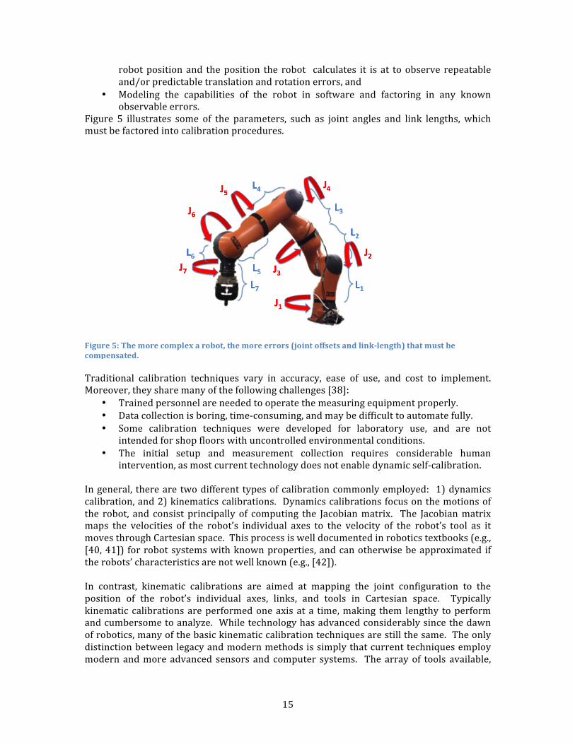
Figure 5 illustrates some of the parameters, such as joint angles and link lengths, whichmustbefactoredintocalibrationprocedures.
Traditional calibration techniques vary in accuracy, ease of use, and cost to implement.Moreover,theysharemanyofthefollowingchallenges[38]:
• Trainedpersonnelareneededtooperatethemeasuringequipmentproperly.• Datacollectionisboring,time-consuming,andmaybedifficulttoautomatefully.• Some calibration techniques were developed for laboratory use, and are not
intendedforshopfloorswithuncontrolledenvironmentalconditions.• The initial setup and measurement collection requires considerable human
intervention,asmostcurrenttechnologydoesnotenabledynamicself-calibration.
Ingeneral, thereare twodifferent typesofcalibrationcommonlyemployed: 1)dynamicscalibration,and2)kinematicscalibrations. Dynamicscalibrationsfocusonthemotionsofthe robot, and consist principally of computing the Jacobianmatrix. The Jacobianmatrixmaps the velocities of the robot’s individual axes to the velocity of the robot’s tool as itmovesthroughCartesianspace.Thisprocessiswelldocumentedinroboticstextbooks(e.g.,[40,41]) forrobotsystemswithknownproperties,andcanotherwisebeapproximated iftherobots’characteristicsarenotwellknown(e.g.,[42]).In contrast, kinematic calibrations are aimed at mapping the joint configuration to theposition of the robot’s individual axes, links, and tools in Cartesian space. Typicallykinematic calibrationsareperformedoneaxisata time,making them lengthy toperformandcumbersometoanalyze. Whiletechnologyhasadvancedconsiderablysincethedawnofrobotics,manyofthebasickinematiccalibrationtechniquesarestillthesame.Theonlydistinctionbetweenlegacyandmodernmethodsissimplythatcurrenttechniquesemploymodernandmoreadvanced sensorsandcomputer systems. Thearrayof tools available,
Figure5:Themorecomplexarobot,themoreerrors(jointoffsetsandlink-length)thatmustbecompensated.
16
though providing more options, may complicate the selection process for calibrations:Measurementdevices[1]usedforcalibrationinclude:
1. Touchprobeswithareferenceartifact[44,45]2. Telescopingballbar3. Camera-based3D(positioning)devices4. Acousticsensors5. Large-range 3D measurement devices such as laser-trackers [46], coordinate
measuring machines, theodolites [47], laser interferometry [35, 48, 49], andphotogrammetry[50].
Each comes with its own advantages and disadvantages. Touch probe with referenceartifact is one of the oldest methods and simplest to use; however, it is best used in acontrolledenvironmentandisnotidealforlargevolumesystems.Telescopingballbarsuseembedded sensors and analysis software to give a relatively simple, rapid check ofpositioning performance that is tied to international standards and are quite familiar tomachinetoolcalibratersacrossthemanufacturingfloor;however,theyareusuallylimitedtoapproximately300mminlengthandcanonlycalibrateone-dimensionatatime.Large-range3Dmeasurementdevicesprovide extremely accurate, large volumemeasurements;however, the equipment is expensive, needs to be calibrated itself, and needs a trainedoperatortosetupandusethedevicebeforecalibratingtherobotsystem.Ratherhavingtocalibrateeachjointoftherobotindividuallyandthenreferenceeachonebacktoacommonreferencepoint, therobot’sendeffectorcouldbetheonlypointcalibrated.Thismayhaveitsownadvantage(shortertimeperiodtocalibrate)anddisadvantage(therobotmaynotknowitsownvolumespace,i.e.,howbigitis!).Researchersareconstantlytryingtofindeasierandquickerwaystocalibraterobots. Forexample,onegroupdevelopeda6D(completepose,consistingoflocationandorientation)measurement system comprised of a camera-based system or a laser tracker with a 6Dprobe(e.g.,telescopingballbarsystem)[1].Bycombiningcalibrationtechniques,theywereable toaccomplish thecalibration inaboutanhour,ata relatively lowcost.However, thesystemonlyhasasmallworkingvolumeof300mmand itdoesnot factor inanysensors(e.g., vision, touch) that theusermaywant touse. Thehunt is stillon for thecalibrationmethodsthatiseasytouse,inexpensive,andquickenoughtoperformonaregularbasis.A robot’s position is a combination of the requested location and the robot errors. Themeasurementdevicementionedabovewill provide lotsofdata;however, it still doesnotnecessarilyprovidearepeatablepositionresponse.Themeasurementdatacombinedwithan appropriate mathematical model (e.g., Denavit-Hartenberg and Denavit-HartenbergModifiedConventions [43],CompleteandParametricallyContinuousModel [44,45],ProductofExponentials[46,47])willimprovetherepresentationofthepositionandorientation(i.e.,thepose)oftherobotend-effector.Thesemathematicalmodelsareafunctionoftherobotjointanglesandtheerrorparametersthatneedtobemodeled.
Robot-CameraCalibration
Anothermethod to approximate robot calibration is through observations of the robot’sworkspaceofspecifictargetpointsusingcalibratedcameras.Iftheobservationalcamera’sintrinsic and extrinsic properties can be calculated, then interpretation of objects in thecamera’sviewcanbeusedtomapoutwhereobjectsareinthe3Dspacebeingobserved.
17
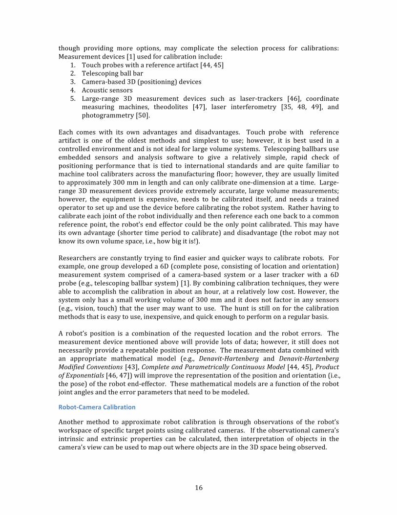
Standardcheckerboardpatternsplacedintherobotworkspacecanbeusedtocalculateacamera’sspecificintrinsicandextrinsicproperties.AnexampleofsuchacheckerboardisshowninFigure6.Aseriesofmulti-imagecapturesarecollectedofthecheckerboardinvariousareasofthecamera’sframe.Theseimagesarethenusedtocalculatethevaluesofthecamera’sspecificpropertiesincluding:position,rotation,focalpoint,skew,anddistortionproperties.Oncethesepropertiesareknown,thenthecameraisconsideredtobeafullycalibratedcamera.
Twomethodshavebeendevelopedfordeterminingarobotarm’spositionandposebasedoncalibratedcameras: onemethodhasthecalibratedcameraattachedtotherobot’sendeffector to be able to calculate a precise view of where the camera is in 3D space andcorrespondinglywhere therobot’sendeffector is in3Dspace. Theothermethodhas thecalibratedcameraasastationarycamera(orstereocamerapairs)atthebaseoftherobotobservingtherobot’spiecesastheymovethroughtherobotspace[48-51].
RobotCalibrationusingCalibratedCameras
Generallyspeaking,thereisalackofageneral-purposeframeworkforcalibratingallofthesensorsandactuatorsofa robot together thataccounts foreachsensor’s individualerrorcharacteristics. A promising new technique [36] allows the combination of data from avarietyofobservationalsensors(laserrange-finders,cameras,stereocameras,etc.) in therobot’sworkspace tobeused alongwith the classic computer vision techniqueof bundleadjustment2to solve the intrinsicandextrinsicpropertiesalongwitherrorestimationsofeach individual sensor used. Once determined, these can be used together to get anaccuratecalculationoftherobot’spositionandpose.Ifthesenewtechniquesareproventobeconsistentlyreliableandaccurateandifstraight-forwardmethodsandinstructionscanbecreatedforrobotmanufacturersand/orSMEstoreplicate these techniques, thenall theadvantagesofhavingaprecision robot calibrationwill be gained. One such attempt at accomplishing this is available for the ROS (RobotOperatingSystem)environment.[52]
2Bundleadjustmentisatechniqueforderivingjointlyoptimal3Dstructureandviewingparameter(cameraposeand/orcalibration)estimates.“Bundle”referstothegroupoflightraysthatemanatefromeachobjectfeatureandconvergeonthecamera’scenter.
Figure6:Checkboardpatternscanbeusedtoregistermultiplesensorsatonetime.
18
Robot-VehicleCalibration
Itisanticipatedthatroboticvehicleswillbeintegraltothefutureoflarge-scaleandflexiblefactoryautomationofassemblytasks. Asnotedabove,automatedguidedvehicles(AGVs),mobile robots, and mobile manipulators (articulated robot arms mounted on mobileplatforms [19]) are anticipated as being critical technologies for agile manufacturingapplications,andultimatelyposethegreatestriskinhuman-occupiedfactoryenvironments.Ensuringthattheirpositionandsensorsystemsarecorrectlycalibratedisessential.Many approaches exist for the calibration and evaluation of marker-less methods forlocalization,morecommonlyknownassimultaneouslocalizationandmapping(SLAM,[53,54],discussedinmoredetaillater).Withinthemanufacturingrealm,however,SLAMdoesnotprovidelocalizationrobustenoughtoensureoptimalpositioningperformanceorsafety,but some results imply such performance may be eventually possible [55]. Otherapproachesuseactivemechanismstoproject fiducials intotheenvironment thatareusedforrangemeasurementandlocalization(e.g.,[56]).However,suchmethodshavenotfoundmuch applicationwithin industry. Instead, typicalmobile platform installations focus onprovidingfixedreferences(e.g.,visualtargetsoreasily-identifiablestructuralcomponents)within the environment to provide suitable localization and navigational support.Commercial options for such fiducials include retro-reflective markers [57], ceiling-mountedbarcodes[58],andwires,visualmarkers,ormagnetsembeddedinthefloor(e.g.,[59]).CommercialAGVsystemshaveknownperformanceaccuracies,thoughtheperformanceofthemobile system is dependent on the extrinsic calibration between the tracking systemand the robot itself. Typically, theAGVwillhavesome formofonboard,odometry-basedsystem that attempts to localize itself through dead reckoning. Odometry-based systemsare dependent on accurate measurements of wheel radii, the baseline between wheels,wheel slip models, and the accuracy and precision of the steering mechanism (e.g.,differential-steeringversusAckerman-steering).Gyro-based internal localization systems (e.g., inertial odometric navigation - ION) gothroughaseriesofknownmotionstocalibratethecontrollaws.DeCecco[60],forinstance,assumestheIONknowsnothingabouttheAGV,andcommandstheAGVtomovethroughaseriesofroundedrectangularpathstoautomaticallygenerateestimatesforthe1)steeringangleatwhichtheinstantaneouscenterofrotationisatinfinity,2)thedrivingwheelradius,3)thedistancebetweenthewheelrotationaxes,and4)thecharacteristicsofthegyroscopeitself. Aninfraredabsolutetriangulationsystem(withanangularuncertaintyof±47arc-seconds and positional accuracy of ±2 mm) provided the inputs into the calibrationprocedure. As a verificationmetric, the calibration values for these characteristicswerecompared with the nominal values provided by the AGV and gyro vendors. In hisexperiment,thistechniquemadeitpossibletoachieveameandifferenceintheendpositionestimationbetweentheabsolutesystemandthenavigationalgorithmofεx=6mm,εy=4mm,εδ=0.2degrees.Thevarianceachievedwasσx=12mm,σy=8mm,σδ=0.6degreesoverapathof25mlong.Censi et al. [61] provide a mobile platform calibration technique for calibrating robotodometryaswellastheextrinsicparametersforalaser-basedlocalizationsystemrelativeto its locationontherobot. Unlikemanyotherapproaches, thismethoddoesnotrequirethe robot to move through known trajectories, though the authors do recommend

19
trajectories be chosen that result in closed loops in confined spaces with relatively lowspeeds to maximize the sample density. Their evaluations were performed on a small,differentially-steeredmobilerobotwithanonboardlaserrangefinder,andthecalibrationverification was done by means of comparing the calibrated estimates with valuesmeasuredmanually(whenpossible)andprovidedinproductspecifications.Kelly and Sukhatme [62] solve the problemof extrinsically calibrating sensors to inertialmeasurementunitsonboardmobilerobotplatforms.Parametersrecoveredduringtheself-calibration include sensor-to-sensor transformations, inertial measurement unit (IMU)biases, local gravity vector, and scene structure by utilizing structure from motion (i.e.,SLAM).Theapproachwasevaluatedinsimulationandinexperiments.Verificationtooktheformofcomparingtheself-calibrationmethodologywithhand-measuredresults.
Robot-Gripper/HandCalibration
Ahighly coveted functionality regardingmulti-fingered, general purpose robotic hands istheir ability to efficiently andeffectivelygraspobjectswithinunstructuredenvironments.Withoutaccurateknowledgeandcontrolovertheenvironment,perceptionandreactivityisofparamountnecessitytorobustinteractivity.Neurophysiologicalresearchhasrepeatedlyshown that humans possess a suite of finger-embedded mechanoreceptors that providesensoryinformationthatisultimatelyresponsibleforourabilitytoproperlyforcemodulateour grasps in the presence of uncertainty and disturbances [63, 64]. Consequently,manystate-of-the art techniques in robotic grasping and manipulation exploit the feedbackcapabilitiesofmanydifferentkindsoffingersensors.Forinstance,contemporarystrategiesrely heavily on measuring contact forces [65-70]. Finger sensors can provide thisinformation through sensory layouts such as load cells, barometers, accelerometers,electrodes, hydrophones, cameras, or some combination thereof. The complexity of thesesensors with application to touch-related events not only lies with their design andintegration,butalsowiththeircalibration.Thatis,inherentlytheyaredesignedtorespondtocertainperturbationsduringcontact,but theirresponsesaremademeaningful throughthe application ofmathematicalmodels. Thesemodels can be complex, and are typicallyappliedofflineonlargereferencedatasetsthathavebeencollected.Furthermore,manyofthesesensorscanexhibitnonlinearresponsedynamicsthatcancomplicatethecalibrationprocess.Generallyspeaking, thedifficultyof thecalibrationprocess for thesecontactsensorsrestswithdatacollectionanddataanalysis.Theparticularexperienceineachofthesecategoriescanvarysignificantlydependingontheparticulardesignandimplementationofthesensoranditsdesiredapplication.
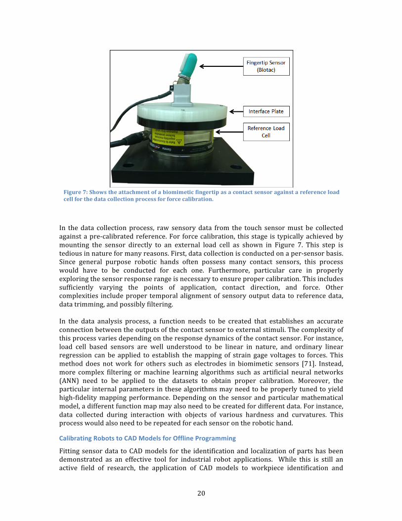
20
In thedata collectionprocess, raw sensorydata from the touch sensormust be collectedagainstapre-calibratedreference.For forcecalibration, thisstage is typicallyachievedbymounting the sensor directly to an external load cell as shown in Figure 7. This step istediousinnatureformanyreasons.First,datacollectionisconductedonaper-sensorbasis.Since general purpose robotic hands often possess many contact sensors, this processwould have to be conducted for each one. Furthermore, particular care in properlyexploringthesensorresponserangeisnecessarytoensurepropercalibration.Thisincludessufficiently varying the points of application, contact direction, and force. Othercomplexities includeproper temporalalignmentof sensoryoutputdata to referencedata,datatrimming,andpossiblyfiltering.In the data analysis process, a function needs to be created that establishes an accurateconnectionbetweentheoutputsofthecontactsensortoexternalstimuli.Thecomplexityofthisprocessvariesdependingontheresponsedynamicsofthecontactsensor.Forinstance,load cell based sensors are well understood to be linear in nature, and ordinary linearregression canbe applied to establish themappingof strain gage voltages to forces. Thismethod does notwork for others such as electrodes in biomimetic sensors [71]. Instead,more complex filtering ormachine learning algorithms such as artificial neural networks(ANN) need to be applied to the datasets to obtain proper calibration. Moreover, theparticularinternalparametersinthesealgorithmsmayneedtobeproperlytunedtoyieldhigh-fidelitymappingperformance.Dependingon thesensorandparticularmathematicalmodel,adifferentfunctionmapmayalsoneedtobecreatedfordifferentdata.Forinstance,data collected during interaction with objects of various hardness and curvatures. Thisprocesswouldalsoneedtoberepeatedforeachsensorontherobotichand.
CalibratingRobotstoCADModelsforOfflineProgramming
Fittingsensordata toCADmodels for the identificationand localizationofpartshasbeendemonstrated as an effective tool for industrial robot applications. While this is still anactive field of research, the application of CAD models to workpiece identification and
Figure7:Showstheattachmentofabiomimeticfingertipasacontactsensoragainstareferenceloadcellforthedatacollectionprocessforforcecalibration.
21
localizationissoeffectivethatsomeconsidertheirusetobeabasicstartingpointformanyofflineprogrammingindustrialrobots[72].CADmodelsoftherobots,themselves,havealsogainedpopularity,andareoftenusedasabasis for evaluating robot workcell design (e.g., [73]), process flow representation (e.g.,[74]),andofflineprogramming(e.g.,[21]).Modelsoftherobotsareloadedintoa3Dvirtualrepresentation of the actual or planned workcells. The kinematics of these models arelinkedtoasimulatedrobotcontroller,allowingforthevisualizationoftherobots’motionsastheywouldbeexecutedbytheirreal-worldcounterparts[75].Suchsimulationsofrobotcontrollers (and the 3D rendered environments) are typically provided by the robotvendors,butthird-partysolutionsaregaininginpopularityfortheirabilitytomodelrobotsandcontrolalgorithmsfrommultiplesources.Another use of CAD models is for the evaluation of robot operational environments forsafety and performance optimization. For instance, in 1992, Yao and Yusoff [76]demonstrated a system in which a material handling workcell for a 4-axis robot wasregisteredtoacommercialCADrepresentationoftheoperationalspace. Thisregistrationforms the basis of an error map that is used for task-oriented, collision-free trajectoryplanningfortherobotwhenevertheenvironmentischanged.Usingtheknownkinematicsoftherobot,positionalerrorsareprojectedthroughoutthemodeledworkingenvironment.Theseerrormodelsprovidethebasisforofflineplanning,programming,anderror-reducedperformanceoptimization.Similartechniquesareusedtodayinopen-sourcedlibrariesfortheoffline,automaticgenerationofcollision-freemotionplanning(e.g.,[77]). Ratherthanrepresenting environments in commercial software, robots and their operationalenvironmentsarecapturedintheunifiedrobotdescriptionformat(URDF)[78]soastobeusablebyROStoolsandlibraries.Inalloftheseexamples,thecalibrationandregistrationofvirtualrobots,workpieces,andenvironments to the real world have been accomplished manually through meticulousmeasurementandverificationprocesses. In thevirtual-real transition,physicalworkcellsareconstructedfromtheoriginalCADmodelswithinsomedegreeofconstructiontolerance,whereas the real-virtual transition is largely based on rough measurements of physicalspacesintegratedwithvendor-provided3Dmodelsoftherobots.Advancesinsensing,processing,anddisplaycapabilitieshavegivenrisetonewapplicationswithaugmentedreality.Insuchsystems(e.g.,[79]),calibratedmarkersareusedtoregisterthe perspective of a vision system to the physical configuration, and a 3D renderedrepresentationoftherobotisprojectedintotheoperator’svisualdisplayforprogrammingandprocessfeedback.
Calibrating Virtual Models to Sensor Data Visionsensor-basedrobotapplicationsrequiresomemodelofthepartsonwhichtherobotsareoperating. Suchapplicationsarehistorically limitedtoroutinematerialhandling(e.g.,part acquisition and inspection), but advances in sensing and robot technologies areenabling expanded applications in the domains of robotic assembly, part manipulation,welding,andsurfacefinishing.Therearetrade-offsbetweenmultiplefactors,includingflexibility,reliability,performance,cost, and ease-of-use depending on which sensors and models are used, however. For
22
example, limited-view model perspectives of the parts for monocular camera capturesystems (e.g.,partsbeingpresented inmatrixkit trays) compromise flexibility in favorofeasierprogrammingand increased reliability. In contrast, CAD-basedmodel fittingof3Dpoint clouddata reduces the restrictiononpartpresentationandgrasping, andenablesabroaderrangeofintelligentapplicationsduetotheabilitytodirectlymapofflineCADdatatoonlineprocesses.Registeringsensorinformationtovirtualmodels(e.g.,CADdata,asdescribedpreviously)isa broad topic that is still actively being investigated. A full survey of such techniques isbeyond the scope of this report, but it is worth mentioning some approaches from theliteraturelandscapehere. Inparticular,wewilldiscusstechniquesfortemplatematching,featurematching,andcross-modalfitting.
TemplateMatching
Templatematching is themostdirectmethodforcomparingvirtualmodelstorawsensorinputs.Here,thevirtualmodelconsistsofanaprioridefinedtemplate(orspecificinstanceorsub-samplesofsensordata),whichisprovidedtotheobserversystem.Thesystemthensearchesthesensorinputforanexactmatchofthattemplatetoidentifyifandwherethattemplate occurs in the data stream. In image-based matching, for instance, an exampleimage of an object or element is provided as a template. That template is then shiftedacross a query image to determine if and where that template image can be found. Acommonimplementationofthismatchingprocessisbymeansofcorrelationcoefficients(ormeasures of similarity) between the archetype template and the raw sensor input. Alimitationof the templatematchingapproach,however, is that templatesmustbedefinedfor every possible instance and orientation of the components to be identified. Certaintransformsmaybeappliedtothetemplates(e.g., inimage-basedmatching,templatesmaybescaled,skewed,orrotated)toidentifytheapproximateoffsetsfromthebasetemplate.Templatematching is best appliedwhen the presentation and tolerances of parts can betightly controlled. Such matching processes are generally not robust against largedeviationsfromthearchetypetemplates(e.g.,partvariationsorshiftsinlightinginimage-basedmatching).Moreover,increasingthesearchspace,numberofcomparisontemplates,or transforms applied to the templates increases the computational cost of identificationand localization. Certain performance optimization tricks such as subsampling [80] orsignalscalingcanbeusedtomitigatehighcomputationalcosts.
FeatureMatching
Incontrastwithtemplatematching,whichrequiresarepresentativesampleforcomparison,featurematchingprovidesidentificationandlocalizationbasedoncollectionsofnumericalrules(orclassifiers). Here,theseclassifiersactasvirtualmodels,andprovidethebasisofassessingsensor inputs. Specificsub-elementsof the inputsareuniquely identifiedbasedonmathematicallyidentifiableaspectsofthesensorspace.Suchaspectsincludeidentifiededges or circles in camera images [81], force and torque profiles in force-based controlmeasurements [82], and specific frequency and magnitude profiles in sound-basedapplications [83]. Multiple classifiers may be used to improve identification andlocalizationbymeansofinter-classifierrelationships.Thematchingprocessconsists largelyofagoodnessof fitmetric,wherethemathematicalfeatures,once identifiedand locatedwithinthe inputsdatastream,areassessedbasedonthe defined inter-classifier relationships. Such assessmentsmay be based on rootmean
23
errors (differences) between the measured values, or in terms of transformationmagnitudesnecessarytofittheclassifierstothedatastream(e.g.,comparingrelationshipsbased on attributes, such as using pattern recognition algorithms like the K-nearestneighborstechniques[84]).Earlierwe introduced a related field of study, simultaneous localization andmapping, orSLAM. Asthenameimplies,SLAMattemptsto identifywherewithinaparameterspaceagiven system is located, while simultaneously characterizing that space. This is mostcommonly applied toward the mobile robot domain, with specific applications in robotnavigationandplanning ([53,54]). BothSLAMandSLAM-basednavigationareextensivefields of research, but the underlying principle is as follows. A robot-mounted sensorsystem measures the distance between the robot and some identified features (orlandmarks) in thesurroundingarea. These featuresmustbebotheasily identifiable (e.g.,flat surfaces or corners) and static. Based on these distance measurements, the robotestimatesitspositionrelativetothesefeaturesbasedonpriorestimatesofpreviouslyseen(andrecorded) features. Thesepositionestimatesmaybecombinedwithdeadreckoningstate estimates based onwheel encoders or open-loop control predictions. As the robotmovesthroughoutthespace,bothitspositionandthemapofidentifiedfeaturesarerefined.Iftherobottraversesthroughthatspaceagain,thegeneratedmapsmaybeusedtoprovidelocalizationcues(e.g.,throughMonteCarloprocesses[85]).Ingeneral,theSLAMprocessislargelyopenloop,asthetruelocationsoftherobotandidentifiedfeaturesareneverknownormeasured.Ingeneral,feature-basedmatchingalgorithmsarebothfastandrobust.However,accuracymaybeimpactedifboundsarenotproperlyplacedonthequalityoffeaturematches,oriftheinitialsetoffeaturesispoorlydefined.Specifically,incontrastwithtemplatematching,the process ofmathematically defining features and theirweights is not always intuitive.Whatappeartobekeyfeaturesforahumantoidentifypartsmaynotworkaswell foranautomatedsystem.Assuch,aconsiderableamountofinitialtrialanderrormayberequired.Similarly,ifthesystemisrequiredtogoopen-loopasinSLAM,evenminormatchingerrorsmay accumulate to produce larger, irrecoverable errors downstream unless concertedeffortsaremadeto“closetheloop”usingestablishedreferencepoints.
Cross-ModalFitting
Inbothtemplateandfeaturematching,virtualmodelsaredefinedwithinthecontextoftheconstituent data streams. There is, however, a significant challenge presentedwhen thevirtualmodelisdefinedinaconfigurationspacethatisnotidenticaltotherawsensorinput.Insuchinstances,onerepresentationmustbetransformedintotheformatoftheother,orbothmustbetransformedintoathirdspacefordirectcomparison.An illustrativeexampleofsuchcross-modal fitting isattemptingtomatchaCADmodel torawred-green-blue-depth(RGBD)data. Insuchcases,boththeCADmodelandtheRGBDdatamustbeprojected into theCartesiancoordinate space. TheRGBDdatawill take theform of a point cloud, while the CAD model will be a geometric solid. The brute-forceapproachexhaustively rotates and shiftsboth thepoint cloudand the soliduntil thebestpossiblefitisfound.Ifallowed,suchanapproachcouldtakeaneternitytocompleteiftheaccuracyrequirementsaretoostringent.AnalternativeapproachistoprojectboththeCADmodelandtheRGBDpointcloudintoyetanotherform(e.g.,shapeproxies[86])thatenablefaster andmore direct comparisons. Other examples of this include converting the CADmodel intoapointcloudforK-nearestneighborevaluation,ortheinverseinwhichaCAD
24
model is generated from point cloud data (i.e., “reverse engineering” [87]). Thistransformative process involves some level of initial computational overhead, butsignificantly reduces the problem complexity. Essentially, the cross-modal problembecomesreducedtoeitheratemplateorafeaturematchingproblem.
Discussion
Inthisreport,weintroducedchallengestointegratingrobotsintomanufacturingprocessesfaced by SMEs as well as largemanufacturers. We drew specific attention to the issuesconcerning robot system calibration and registration, and presented a number ofapproaches from the literature to address many of the calibration and registrationchallenges.Clearly,calibrationandregistrationissuesarebutasmallfractionofthebarrierstosmall-and medium-sized enterprises accepting robot technologies. However, these issues arecentral to the performance of any robot integrated into amanufacturing process. Beingawareofboth thenatureof thechallengesand theexistenceofapproaches toaddressingthose challenges is critical to acceptance. The processes of calibrating and registeringrobots to other systems are difficult and time consuming. As the needs and concerns ofSMEs becomewell documented and understood, new, user-friendly tools are expected tobecomeavailabletoutilizecalibrationandregistrationtechniqueswithminimaleffort.This endeavor, however, cannot be completed in a vacuum, or without the activeparticipation of SMEs. New standards may be written to address the requirements forproviding assurance of system performance. But without the inputs of SMEs, thesestandardsareunlikelytoaddressthebroadspectrumofstakeholderpreferences.Similarly,newtechnologiesandtoolsmaybedevelopedtoeasetheintellectualburdenofcalibrationandregistration.Yet,ifSMEsareeitherunawareoftheirexistenceorunwillingtoprovidefeedbackon experimental systems, these technologies areunlikely to find theirwayontothe manufacturers’ shop floors. Therefore, a convening of all the interested parties isneededtoachieveprogressintheadoptionofroboticsbySMEs.Thisreportisintendedtoserveasastartingpointforthediscussionsandformulationofactionplansleadingtowardsthe development of accurate and easy to implement toolkits for reducing the burden ofcalibrationandregisteringofroboticworkcells.
25
Bibliography
1. Nubiola,A.andI.A.Bonev,Absoluterobotcalibrationwithasingletelescopingballbar.PrecisionEngineering,2014.38:p.472-480.
2. ComputingCommunityConsortium,WorkshoponOpportunitiesinRobotics,Automation,andComputerScience.2014:http://www.cra.org/ccc/files/docs/meetings/NSF-OSTP-CCC-RVO-Workshop-Report-Oct21-2013.pdf.
3. Marvel,J.A.,CollaborativeRobotics:AGatewayintoFactoryAutomation,inThomasNetNews.2014:http://news.thomasnet.com/IMT/2014/09/03/collaborative-robots-a-gateway-into-factory-automation/.
4. Lavars,N.,Factory-in-a-Dayprojectaimstodeploywork-readyrobotswithin24hours,inGizmag.2014:http://www.gizmag.com/factory-in-a-day/30053/.
5. Union,E.Factory-in-a-Day.201323September,2014];Availablefrom:http://www.factory-in-a-day.eu/
6. Barajas,L.G.,A.L.Thomaz,andH.I.Christensen.UsheringintheNextGenerationofFactoryRobotics&Automation.inNationalWorkshoponChallengetoInnovationinAdvancedManufacturing:IndustryDriversandR&DNeeds.2009.
7. InternationalFederationofRobotics.Statistics-IFRInternationalFederationofRobotics.2014[cited2014;Availablefrom:http://www.ifr.org/industrial-robots/statistics/.
8. Knight,W.,Increasingly,robotsofallsizesarehumanworkmates,inMITTechnologyReview.2014.
9. Orcutt,M.ManufacturersAddingRobotstotheFactoryFloorinRecordNumbers.2014[cited201503February];Availablefrom:http://www.technologyreview.com/graphiti/529971/robots-rising/.
10. Whitney,D.E.,Mechanicalassemblies:theirdesign,manufacture,androleinproductdevelopment.Vol.1.2004:OxfordUniversityPress.
11. Shneier,M.,etal.,MeasuringandRepresentingthePerformanceofManufacturingAssemblyRobots.2015,NationalInstituteofStandardsandTechnology:Gaithersburg,MD.
12. Dafle,N.C.,etal.Extrinsicdexterity:In-handmanipulationwithexternalforces.inRoboticsandAutomation(ICRA),2014IEEEInternationalConferenceon.2014.IEEE.
13. ComputingCommunityConsortium,AroadmapforUSrobotics:FromInternettorobotics.2013:http://www.us-robotics.us/reports/CCCReport.pdf.
14. Okamura,A.M.,N.Smaby,andM.R.Cutkosky,Anoverviewofdexterousmanipulation,inIEEEInternationalConferenceonRoboticsandAutomation.2000:SanFrancisco,CA,USA.p.255-262.
15. Falco,J.,J.Marvel,andE.Messina,DexterousManipulationforManufacturingApplicationsWorkshop,N.I.o.S.a.Technology,Editor.2013:http://www.nist.gov/el/isd/upload/NIST-IR-7940.pdf.
16. Gray,T.,D.Orf,andG.Adams,MobileAutomatedRoboticDrilling,Inspection,andFastening.2013,SAETechnicalPaper.
17. Li,X.,etal.Automaticofflineprogramcalibrationinroboticcells.inCyberTechnologyinAutomation,Control,andIntelligentSystems(CYBER),2014IEEE4thAnnualInternationalConferenceon.2014.IEEE.
18. Lewis,J.,ElementsofSuccessfulVision-GuidedRobotics,inAssembly.2013.19. Marvel,J.A.andR.Bostelman,Towardsmobilemanipulatorsafetystandards,inIEEE
InternationalSymposiumonRoboticandSensorsEnvironments.2013:Washington
26
D.C.p.31-36.20. Chen,H.,T.Fuhlbrigge,andX.Li,AreviewofCAD‐basedrobotpathplanningfor
spraypainting.IndustrialRobot:AnInternationalJournal,2009.36(1):p.45-50.21. Neto,P.,J.N.Pires,andA.P.Moreira,CAD-basedoff-linerobotprogramming,inIEEE
ConferenceonRoboticsAutomationandMechatronics(RAM).2010.p.516-521.22. daMotta,J.M.S.,C.A.G.deSousa,andF.A.Afonso.Anoff-linerobotprogramming
systemincludingworkcellandrobotcalibration.inABCMSymposiumSeriesinMechatronics.2004.
23. Bergström,G.,Methodforcalibratingofoff-linegeneratedrobotprogram,inDepartmentofAutomaticControl.2011,ChalmersUniversityofTechnology.
24. Dynalog.IntegratedOLPprocessatJCIusingDynaCal.[cited2015January6,2015];Availablefrom:http://www.dynalog-us.com/dynalogmainsite_005.htm.
25. Helms,E.,R.D.Schraft,andM.Hägele,rob@work:Robotassistantinindustrialenvironments,in11thIEEEInternationalWorkshoponRobotandHumanInteractiveCommunication.2002:Berlin,Germany.p.399-404.
26. Marvel,J.A.,J.Falco,andI.Marstio,Characterizingtask-basedhuman-robotcollaborationsafetyinmanufacturing.IEEETransactionsonSystemsScienceandCybernetics:Systems,2015.45(2):p.260-275.
27. Abd,K.,K.Abdhary,andR.Marian,Aschedulingframeworkforroboticflexibleassemblycells.KingMongkut'sUniversityofTechnologyNorthBangkok:InternationalJournalofAppliedScienceandTechnology,2011.4(1):p.31-38.
28. Nof,S.Y.andZ.Drezner,Themultiple-robotassemblyplanproblem.JournalofIntelligentandRoboticSystems,1993.5:p.57-71.
29. Hsieh,S.-F.,Re-configurabledual-robotassemblysystemdesign,developmentandfuturedirections.IndustrialRobot:AnInternationalJournal,2003.30(3):p.250-257.
30. Fu,L.-C.andY.-J.Hsu,Fullyautomatedtwo-robotassemblycell,inIEEEInternationalConferenceonRoboticsandAutomation.1993:Atlanta,GAUSA.p.332-338.
31. Glibert,P.-R.,etal.,Schedulingofamulti-robotassemblycell.ComputerIntegratedManufacturingSystems,1990.3(4):p.236-245.
32. Lee,J.-K.andT.-E.Lee,Automata-basedsupervisorycontrollogicdesignforamulti-robotassemblycell.InternationalJournalofComputerIntegratedManufacturing,2010.15(4):p.319-334.
33. Bonert,M.,L.H.Shu,andB.Benhabib,Motionplanningformulti-robotassemblysystems.InternationalJournalofComputerIntegratedManufacturing,2010.13(4):p.301-310.
34. Mooring,B.W.,Z.S.Roth,andM.R.Driels,FundamentalsofManipulatorCalibration.1991:JohnWiley&Sons,Inc.
35. Tsai,T.-M.,CameraCalibrationforaManufacturingInspectionWorkstation.2005,USDepartmentofCommerce,TechnologyAdministration,NationalInstituteofStandardsandTechnology.
36. Pradeep,V.,K.Konolige,andE.Berger.Calibratingamulti-armmulti-sensorrobot:Abundleadjustmentapproach.inExperimentalRobotics.2014.Springer.
37. Roth,Z.S.,B.Mooring,andB.Ravani,Anoverviewofrobotcalibration.RoboticsandAutomation,IEEEJournalof,1987.3(5):p.377-385.
38. Elatta,A.Y.,etal.,AnOverviewofRobotCalibration.InformationTechnologyJournal,2004.3(1):p.74-78.
39. Roth,Z.S.,B.W.Mooring,andB.Ravani,Anoverviewofrobotcalibration.IEEEJournalofRoboticsandAutomation,1987.3(5):p.377-385.
40. Jazar,R.N.,TheoryofAppliedRobotics:Kinematics,Dynamics,andControl.2nded.2010:SpringerScience+BusinessMedia.
27
41. Kafrissen,E.andM.Stephens,IndustrialRobotsandRobotics.1984,Reston,Virginia:RestonPublishingCompany,Inc.
42. Piepmeier,J.A.,G.V.McMurray,andH.Lipkin,AdynamicJacobianestimationmethodforuncalibratedvisualservoing,inIEEE/ASMEInternationalConferenceonAdvancedIntelligentMechatronics.1999:Atlanta,GA,USA.p.944-949.
43. Wikipedia.HartenbergParameters.201424September,2014];Availablefrom:http://en.wikipedia.org/wiki/Denavit%E2%80%93Hartenberg_parameters.
44. Zhuang,H.,Z.S.Roth,andF.Hamano,Acompleteandparametricallycontinuouskinematicmodelforrobotmanipulators.IEEETransactionsonRoboticsandAutomation,1992.8(4):p.451-463.
45. Zhuang,H.andZ.S.Roth,RobotcalibrationusingtheCPCerrormodel.RoboticsandComputer-IntegratedManufacturing,1992.9(3):p.227–237.
46. Brocket,R.W.,Roboticmanipulatorsandtheproductofexponentialsformula,inInLectureNotesinControlandInformationSciences:MathematicalTheoryofNetworksandSystems.1984.p.120-129.
47. Tao,P.Y.,etal.,Product-Of-Exponential(POE)ModelforKinematicCalibrationofRobotswithJointCompliance,inIEEE/ASMEInternationalConferenceonAdvancedIntelligentMechatronics.2012.p.496-501.
48. Augustson,T.M.,VisionBasedIn-SituCalibrationofRobots:withApplicationinSubseaInterventions,inMechanicalEngineeringDepartment.2007,PontificiaUniversidadeCatolicadoRiodeJaneiro:LapLambertAcademicPublishing.
49. Du,G.andP.Zhang,Onlinerobotcalibrationbasedonvisionmeasurement.RoboticsandComputer-IntegratedManufacturing,2013.29(6):p.484-492.
50. Meng,Y.andH.Zhuang,Autonomousrobotcalibrationusingvisiontechnology.RoboticsandComputer-IntegratedManufacturing,2007.23(4):p.436-446.
51. Motta,J.M.c.S.T.,G.C.d.Carvalho,andR.S.McMaster,Robotcalibrationusinga3Dvision-basedmeasurementsystemwithasinglecamera.RoboticsandComputer-IntegratedManufacturing,2001.17(6):p.487-497.
52. ROS.ROS(RobotOperatingSystem)-Industrial’sMulti-CameraExtrinsicCalibrationwithaTargetpackage.[cited2015May6];Availablefrom:http://wiki.ros.org/industrial_extrinsic_cal/Tutorials/Multi_camera_calibration.
53. Durrant-Whyte,H.andT.Bailey,Simultaneouslocalizationandmapping:PartI,inIEEERoboticsandAutomationMagazine.2006.p.99-110.
54. Bailey,T.andH.Durrant-Whyte,Simultaneouslocalizationandmapping(SLAM):PartII,inIEEERoboticsandAutomationMagazine.2006.p.108-117.
55. Wang,C.-C.,C.Thorpe,andS.Thrun,Onlinesimultaneouslocalizationandmappingwithdetectionandtrackingofmovingobjects:THeoryandresultsfromagroundvehicleincrowdedurbanareas,inIEEEInternationalConferenceonRoboticsandAutomation.2003:Taipei,Taiwan.p.842-849.
56. Reid,I.D.,Projectivecalibrationofalaser-striperangefinder.ImageandVisionComputing,1996.14(9):p.659-666.
57. GöttingKG.LaserScannerforNavigation.2014[cited20141October];Availablefrom:http://www.goetting-agv.com/components/43600.
58. TotalTrax,I.TheSky-TraxSystem.2014[cited20141October];InformationpagefortheSky-Traxforkliftlocalizationsystem.Includesafewcasestudies(PDFs)atthebottomofthepage.].Availablefrom:http://totaltraxinc.com/index.php/smart-forklift-solutions/forklift-tracking/sky-trax.
59. GöttingKG.IntroductionInductiveTrackGuidance.2014[cited20141October];Availablefrom:http://www.goetting-agv.com/components/inductive/introduction.
60. DeCecco,M.D.,Self-calibrationofAGVinertial-odometricnavigationusingabsolute-
28
referencemeasurements,inIEEEInstrumentationandMeasurementTechnologyConference.2002:Anchorage,AK,USA.p.1513-1518.
61. Censi,A.,etal.,Simultaneouscalibrationofodometryandsensorparametersformobilerobots.IEEETransactionsonRobotics,2013.29(2):p.475-492.
62. Kelly,J.andG.S.Sukhatme,Visual-intertialsensorfusion:Localization,mappingandsensor-to-sensorself-calibration.InternationalJournalofRoboticsResearch,2011.30(1):p.56-79.
63. Johansson,R.S.andR.Flanagan,Codinganduseoftactilesignalsfromthefingertipsinobjectmanipulationtasks.NatureReviewNeuroscience,2009.10:p.245-259.
64. Johansson,R.S.,C.Häger,andR.Riso,Somatosensorycontrolofprecisiongripduringunpredictablepullingloads.ExperimentalBrainResearch,1992.89:p.192-203.
65. Glossas,N.I.andN.A.Aspragathos,Fuzzylogicgraspcontrolusingtactilesensors.Mechatronics,2001.11(7):p.899-920.
66. Sadigh,M.J.andH.Ahmadi,Robustcontrolalgorithmforsafegraspingbasedonforcesensing,inIEEEInternationalConferenceonRoboticsandBiomimetics.2008:Bangkok,Thailand.p.1279-1284.
67. Ascari,L.,etal.,Bio-inspiredgraspcontrolinarobotichandwithmassivesensorialinput.BiologicalCybernetics,2009.100(2):p.109-128.
68. Sadigh,M.J.andH.Ahmadi,Safegraspingwithmulti-linkfingersbasedonforcesensing,inIEEEInternationalConferenceonRoboticsandBiomimetics.2009,1796-1802:Guilin,China.
69. Romano,J.M.,etal.,Human-inspiredroboticgraspcontrolwithtactilesensing.IEEETransactionsonRobotics,2011.27(6):p.1067-1079.
70. Boughdiri,R.,etal.,Dynamicmodelingandcontrolofamulti-fingeredrobothandforgraspingtask,inInternationalSymposiumonRoboticsandIntelligentSensors.2012.p.923-931.
71. Wettels,N.andG.E.Loeb,Hapticfeatureextractionfromabiomimetictactilesensor:Force,contactorlocationandcurvature,inIEEEInternationalConferenceonRoboticsandBiomimetics.2011:Phuket,Thailand.p.2471-2478.
72. Pan,Z.,etal.,Recentprogressonprogrammingmethodsforindustrialrobots.RoboticsandComputerIntegratedManufacturing,2012.28:p.87-94.
73. Adam,G.K.andE.Grant,QMTOOL-AqualitativemodellingandsimulationCADsystemfordesigningautomatedworkcells,inIEEEInternationalConferenceonRoboticsandAutomation.1994:SanDiego,CA.p.1141-1146.
74. Jongeling,R.andT.Olofsson,Amethodforplanningofwork-flowbycombineduseoflocation-basedschedulingand4DCAD.AutomationinConstruction,2007.16(2):p.189-198.
75. Harrison,W.S.,VirtualFusion:TheIntegrationandAnalysisofSimulationandRealProcessesforManufacturingProcessDeployment,inMechanicalEngineering.2011,UniversityofMichigan.
76. Yao,Y.L.andM.R.M.Yusoff,ACAD-basedmappingandlayoutfacilityforprecisionroboticoperations.RoboticsandComputerIntegratedManufacturing,1992.9(6):p.505-511.
77. Chitta,S.,I.Sucan,andS.Cousins,MoveIt![ROSTopics],inIEEERoboticsandAutomationMagazine.2012.p.18-19.
78. Meüssen,W.,J.Hsu,andR.Diankov.URDF-UnifiedRobotDescriptionFormat.2014[cited20153February];Availablefrom:http://www.ros.org/wiki/urdf.
79. Girbacia,F.,M.Duguleana,andA.Stavar,Off-lineprogrammingofindustrialrobotsusingco-locatedenvironments.AdvancedMaterialsResearch,2012:p.1654-1657.
80. Vanderbrug,G.J.andA.Rosenfeld,Two-stagetemplatematching.IEEETransactions
29
onComputers,1977.c-26(4):p.384-393.81. Forsyth,D.A.andJ.Ponce,ComputerVision:AModernApproach.2003,UpperSaddle
River,NewJersey,USA:PrenticeHall.82. Skubic,M.andR.A.Volz,Acquiringrobust,force-basedassemblyskillsfromhuman
demonstration.IEEETransactionsonRoboticsandAutomation,2000.16(6):p.772-781.
83. Kashino,K.,T.Kurozumi,andH.Murase,Aquicksearchmethodforaudioandvideosignalsbasedonhistogrampruning.IEEETransactionsonMultimedia,2003.5(3):p.348-357.
84. Peterson,L.E.,K-nearestneighbor.Scholarpedia,2009.4(2):p.1883.85. Thrun,S.,etal.,RobustMonteCarlolocalizationformobilerobots.Artificial
Intelligence,2001.128:p.99-141.86. Schnabel,R.,R.Wahl,andR.Klein,EfficientRANSACforpoint-cloudshapedetection.
ComputerGraphicsForum,2007.26(2):p.214-226.87. Durupt,A.,etal.,Froma3DpointcloudtoanengineeringCADmodel:aknowledge-
product-basedapproachforreverseengineering.VirtualandPhysicalPrototyping,2008.3(2):p.51-59.