Embed Size (px)
Citation preview

Decision Support Systems 13 (1995) 35-59 35 North-Holland
Tools for building the human-computer interface of a decision support system
Sukumar Rathnam a,, and Michael V. Mannino b " Scopus Technology, Emeryville, CA 94608, USA h Department of Management Science, 370 MacKenzie Hall DJ-lO, University of Washington, Seattle, WA 98185, USA
There has been a recent trend towards using graphical, direct-manipulation interfaces in Decision Support Systems (DSS). The development of graphical, direct-manipulation interfaces for a DSS is often expensive in programming re- sources and elapsed time. To reduce the time and cost of interface development, User Interface Management Systems (UIMS) have been developed. The guiding principles of UIMSs are the re-use of interface code, the promotion of interfaces with a consistent "look and feel", and the separa- tion of the functional part of an application from its interface. UIMSs have not been as successful as expected, even if due consideration is given to the immaturity of the technology. We feel this is due to a poor understanding of the basic theoreti- cal formalisms and software design principles for UIMSs as well as the variety of competing standards. This expository paper surveys UIMSs and their role in the construction of the human-computer interface of DSSs. It covers the formalisms underlying UIMSs and describes representative systems. It then describes the direction DSS interfaces are headed to- wards by presenting illustrative examples of recent systems. Finally, we raise a set of six issues that need to be addressed if UIMSs are to become a standard tool to build DSSs.
Keywords." User interface; User interface management sys- tem; Interaction modelling; DSS implementation
"By both research and acclamation, an interface developer's role is now generally accepted to be that of a non-programmer. To address this tools to support interface development need to use sophisti- cated techniques to provide the functionality and power needed to design and execute an interface."
Correspondence to: S. Rathnam, Scopus Technology, 1900 Powell Street, Suite 900, Emeryville, CA 94608, USA. i Our thanks are due to Christopher V. Jones - the guest
editor, and the anonymous referees for providing us ex- tremely useful directions in revising and extending the scope and content of the paper.
1. Introduction
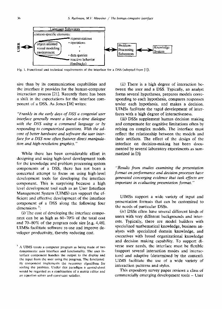
The human-computer interface ~ (language subsystem) along with the problem processing subsystem and the knowledge system is one of the three principle components of a decision support system (DSS) [5]. Fig. 1 describes the technical and functional requirements of the interface component of a DSS.
The success/failure of a DSS is increasingly judged less by its processing speed and problem
Sukumar Rathnam is the Scopus Fel- low at Scopus Technology. He holds a B.Tech in Computer Science from liT Madras, a PGDM from IIM Ahmed- abad and a Ph.D. from the University of Texas, Austin. His research awards include the IBM doctoral fellowship and the Phillips Petroleum IS re- search award. His research interests include computer graphics, object-ori-
~ " ~ ented programming, and coordination ~ theory. For his dissertation he was
awarded a grant by the Marketing Science Institute and recognized as the most outstanding doctoral student. He won the John Howard award from the American Marketing Association for his Ph.D. dissertation. He has published papers in Mathematical and Computer Modeling, Interfaces, IEEE Expert, ICIS, HICSS, ACM COCS, and IFIP WG8.3/8.4.
Michael V. Mannino received a B.B.A. degree from the University of Cincinnati in 1978 and an M.S. and a Ph.D. degree both from the Univer- sity of Arizona, Tucson in 1981 and 1983, respectively. Previously, he was faculty member in the Computer and Information Sciences Department at the University of Florida and in the Department of Management Science and Information Systems at the Uni- versity of Texas at Austin. He joined the Department of Management Sci-
ence, University of Washington, Seattle in September 1991. Dr. Mannino teaches and conducts research in the areas of database management, software engineering, and knowledge representation. His articles have appeared in major journals including IEEE Transactions on Software Engineering, IEEE Transactions on Knowledge and Data Engineering, ACM Computing Surveys, Communications of the ACM, MIS Quarterly, Journal of Management Information Systems, and ORSA Journal on Computing.
2 For the rest of this paper the term interface will be used synonymously with the term human-computer interface.
0167-9236/95/$09.50 ©1995 - Elsevier Science B.V. All rights reserved SSDI 0 1 6 7 - 9 2 3 6 ( 9 3 ) E 0 0 3 0 - H
36 S. Rathnam, M.V. Mannino / The human-computer interface
Language Subsystem context-specific elements:
representations fobject oriented~ • operations
~ " ~ ' ~ visual modeling I ~,environment J
• data queries ~ reactive behavior
(feedbacks)
Fig. 1. Functional and technical requirements of the interface for a DSS (adapted from [1]).
~ P r o b l e m - ~ Knowledge Pr°cessing Fq~----~-~ System I Subsystem
size than by its communication capabilities and the interface it provides for the human-computer interaction process [21]. Recently there has been a shift in the expectations for the interface com- ponent of a DSS. As Jones [38] writes:
"Frankly in the early days of DSS a congenial user interface generally meant a line-at-a-time dialogue with the DSS using a command language or by responding to computerized questions. With the ad- vent of better hardware and software the user inter- face for a DSS now often features direct manipula- tion and high-resolution graphics."
While there has been considerable effort in designing and using high-level development tools for the knowledge and problem processing system components of a DSS, there has not been a concerted at tempt to focus on using high-level development tools for developing the interface component. This is surprising because a high level development tool such as an User Interface Management System (UIMS) can support the ef- ficient and effective development of the interface component of a DSS along the following four dimensions 3:
(i) The cost of developing the interface compo- nent can be as high as 60-70% of the total cost and 70-80% of the program code size [e.g. 4,48]. UIMSs facilitate software re-use and improve de- veloper productivity, thereby reducing cost.
3 A UIMS treats a computer program as being made of two components: user interface and functionality. The user in- terface component handles the output to the display and the input from the user using the program. The functional- ity component implements the necessary algorithms for sovling the problem. Under this paradigm a spread-sheet would be regarded as a combination of a matrix editor and an equation solver and constraint satisfier.
(ii) There is a high degree of interaction be- tween the user and a DSS. Typically, an analyst forms several hypotheses, prepares models corre- sponding to each hypothesis, compares responses under each hypothesis, and makes a decision. UIMSs facilitate the rapid development of inter- faces with a high degree of interactiveness.
(iii) DSSs supplement human decision making and compensate for cognitive limitations often by relying on complex models. The interface must reflect the relationship between the models and their artifacts. The effect of the design of the interface on decision-making has been docu- mented by several laboratory experiments as sum- marized in [3]:
"Results from studies examining the presentation format on performance and decision processes have generated converging evidence that task effects are important in evaluating presentation format."
UIMSs support a wide variety of input and presentation formats that can be customized to the needs of particular DSSs.
(iv) DSSs often have several different kinds of users with very different backgrounds and inter- ests. Typically, there are model builders with specialized mathematical knowledge, business an- alysts with specialized domain knowledge, and executives with broad organizational knowledge and decision making capability. To support di- verse user needs, the interface must be flexible (support several interaction modes and interac- tors) and adaptive (determined by the context). UIMS facilitate the use of a wide variety of interaction patterns and styles.
This expository survey paper reviews a class of commercially emerging development tools - User

S. Rathnam, M.V. Mannino / The human-computer interface 37
Interface Management Systems - that facilitate the development of interfaces for DSS by reduc- ing their cost and improving their quality. This expository review of UIMS technology and its relationship to DSS has three motivating factors:
(i) Software tools and technologies used to develop interfaces for DSSs are widely available. From the viewpoint of a practitioner in the DSS field, choosing a development tool (especially one that must integrate with existing tools) is a com- plex process that involves several trade-offs. A review of UIMS tools and technologies which maps features of UIMSs to the characteristics of DSSs highlights the impacts of making these trade-offs.
(ii) The defining characteristics of DSSs are undergoing a significant change [43]. Current DSSs are more user-centred and often exploit visual modelling (the process of stating a problem in two or more dimensions) and model visualiza- tion (the process that depicts the ongoing effects of executing a model) [59]. In such systems pro- viding effective human-computer interaction is essential [1]. UIMSs offer a technological solution to the problem of rapid development of high quality interfaces. By describing the theoretical foundations of UIMS technology as well as benchmark systems, this paper serves as a vehicle for technology transfer between a problem on the one hand (developing interfaces for DSSs) and the availability of tools (UIMSs) to solve the problem on the other.
(iii) From the viewpoint of the researcher in the DSS field, the review identifies gaps that exist in current tools and potential areas for future research. In particular, we discuss six basic issues about using UIMS of which DSS developers should be aware.
Since our paper is expository in nature and uses a literature survey as its methodological ba- sis, we first summarize UIMS research and then present the linkage to DSS development technol- ogy. In section 2 we present a brief introduction to UIMS. In sections 3, we review the theoretical basis for UIMSs. Section 4 describes some of the prominent UIMSs. Section 5 describes the inter- faces of three DSS applications with special em- phasis on their unique features. Section 6 raises the set of six issues that need to be considered by developers of DSSs who use UIMS. Section 7 concludes the paper.
2. Basics: an introduction to UIMS
In keeping with the expository nature of this paper we now present an introduction to UIMS for readers not familiar with the area (others can skip to section 3). To avoid the terminological confusion that is widely prevalent in the literature and the field at large, we clarify the terminology used in this paper through the following defini- tions are drawn from Scheifler et al. [63] and Myers [52]: • A programming interface is a library of rou-
tines and types provided in a programming language/environment for interacting with a windowing system.
• An application interface is the mechanical in- teraction with the user and the visual appear- ance that is specific to the application.
• A management interface is the mechanical in- teraction with the user, dealing with overall control of the desktop and the input devices. The management interface defines how appli- cations are arranged and re-arranged on the screen, and how the user switches between applications.
• The human-computer interface is the sum total of the previous three kinds of interfaces.
• A user-interface toolkit is a library of interac- tion techniques (such as menus, scroll bars and sliders), where an interaction technique is a way of using a physical device, to receive input, and provide feedback.
• A User Interface Management System (UIMS) is a tool that helps a programmer create and manage all the aspects of a human-computer interface. The term was introduced by David Kasik in 1982 [41].
• The person who designs a human-computer interface and thus uses a UIMS is called the designer.
• The person who creates the application which uses the interface is called the application pro- grammer.
• The person who finally uses the finished prod- uct is called the end-user. Research in and the development of user in-
terface tools have been driven by the emergence of direct manipulation interfaces, software engi- neering concerns of re-usability and interface independence, and the iterative nature of inter- face design. Direct manipulation interfaces sup-

38 S. Rathnam, M.V. Mannino / The human-computer Otterface
port graphic display, multiple modes for execut- ing a given command, control multiple, asyn- chronous input and output devices, involve mode-free dialogue 4, and provide a high degree of semantic feedback 5 [65]. They have become the most popular and easy to use interfaces. However, by their very nature, they are complex to build without appropriate tools.
In traditional approaches to DSS develop- ment, program variables can be used by both the interface code and the application functionality. The state-oriented approaches to system develop- ment, in which program variables affected by interface variables are the same as those used by functionality and vice-versa, can result in a mass of spaghetti code. For reasonably sized applica- tions the interface code can be as much as 80% of the total code [52]. Re-usability is one way to reduce the cost of interface development. Reuse of interface code through the use of UIMS can reduce development time by a factor of 4 to 5 [64]. Reuse of code also gives the interface a consistent "look-and feel". 6
Another way to reduce the cost of interface development is to provide a layer between the application functionality and the interface. There is a well defined separation of concerns between developing the interface to a program and the program itself [52]. Maintenance costs can be reduced if changes to an interface do not affect the underlying application functionality. 7
Because of the complexity of direct manipula- tion interfaces, interface development requires an
4 Direct manipulat ion interfaces have a coroutine like struc- ture and, despite appearances, a highly moded dialogue [34]. This is not a contradiction, and depends on the level of abstraction being considered - to the user the dialogue is mode-free but to the application the dialogue is moded. In practise the dialogue modes are determined by the context.
s (Semantic feedback involves determining the appropriate response based on the context. For example, in the Apple Macintosh interface an icon highlights when another icon is dragged over the first one and semantically meaningful operations are possible between the two objects. In general, and in the specific case of a DSS, consistency in the human-compute r interface can be disadvantageous. For an excellent paper on this topic refer to [27].
7 Note that an interface between the application functionality and interface (the user interface) must be provided. The nature of this interface (how much information and how is it communicated) is a main design variable in UIMS re- search.
iterative process of testing and re-design. The Xerox Star, for example, was built using an "iter- ative design" methodology [52]. An iterative de- sign process requires software support in the form of rapid prototyping tools. As Myers writes [52]:
"The only reliable way to generate quality inter- faces is to test prototypes with users and modify the design based on their comments."
To initially meet these requirements, user in- terface toolkits were developed as an extension of graphics libraries such as Core [22], GKS [6] and PHIGS [9]. User interface toolkits, such as the Macintosh toolbox, SunTools [69] and the X Toolkit for the X Window system manager, in- clude routines to manage windows, perform graphics, and manipulate text. The toolkits are often organized in an object-oriented (OO) man- ner to increase their re-usability. However, the size and complexity of the toolkits (they can con- tain hundreds, if not thousands of sub-routines) as well as the need for access by non-pro- grammers has necessitated the need for higher level development tools such as UIMSs.
Since its birth in the early 1980's, the field of UIMS has resulted in the development of several commercially available tools such as NextStep [75], and Prototyper [67]. UIMSs are often built over existing window managers and use OO tech- niques. Besides providing the functionality and programming interface (callable subroutine li- braries) of toolkits, UIMSs furnish mechanisms for describing desired combinations and se- quences of interaction techniques. These specifi- cations are processed by a UIMS development module to yield a user interface definition. The run-time component of a UIMS forms a part of the final application and draws on the user inter- face definition to provide an effective user inter- face.
As opposed to toolkits, UIMSs enforce the separation between the interface and the applica- tion functionality components of the DSS at both the physical level - code modules - as well as the logical level - data structures. Similarly explicit linking mechanisms between the two components are usually provided at the micro-communication and action level. Again, in contrast to the proce- dural programming language interface of toolkits, a UIMS supports interface development at the

S. Rathnam, M.V. Mannino / The human-computer interface 39
Presentation ~ , , q ' Dialogue Control ~ Application interface model
Fig. 2. The Seeheim model.
interaction level, i.e., in terms of action and reac- tion to high level events. A UIMS provides non- procedural techniques to specify an interface and then generates code or interprets the specifica- tion to implement the interface. Thus, UIMSs are often targeted towards non-programming inter- face experts and support rapid prototyping.
3. Theoretical foundations: the formal basis for UIMS
Since every UIMS needs to have an abstract model of the human-computer interaction pro- cess, our focus, in this section, is to deal with the formalisms that are used to specify and model this process. The formalism that underlies an UIMS has a direct bearing on the nature of the programming interface and therefore on the de- sign of the UIMS and consequently the imple- mentat ion of the DSS.
The Seeheim model (Fig. 2) of interfaces de- scribes the total human-computer interface in terms of three components: a presentation com- ponent, dialogue control and an application inter- face model [26]. The presentation component is responsible for token generation and passing. It corresponds to the lexical level of the interface. The dialogue control is responsible for the struc- ture of the commands and dialogue used by the user. It corresponds to the syntactic level of the interface. The application interface model de- fines the interface between the human-computer interface and the rest of the DSS (knowledge system and problem processing system). It is typi- cally a collection of procedures invoked from the syntactic level that implements the functional re- quirements of the system. It corresponds to the semantic level of the interface.
Using the conceptual framework of the See- heim model, we examine the following for- malisms: transition networks, formal languages, event-based approaches, constraint modelling, di- rect graphical specification, and Higraphs. For each we present its nature, a brief formal defini-
tion, and its pros and cons. s For a fuller treat- ment of these formalisms and UIMSs based on these models the reader is referred to [58].
3.1. Transition networks [26]
This formalism is one of the three major mod- els traditionally used to describe interfaces. Tra- ditionally, transition networks have been used to model the dialogue part of the interface. A tran- sition network consists of a set of nodes repre- senting states and a set of arcs representing user actions. The arcs determine how the dialogue moves from one state to another. To manage large transition networks, sub-diagrams are used. Sub-diagrams are complete transition networks that can be called by or invoked from another sub-diagram. If recursive calls are allowed, the network is called a recursive transition network (RTN). Recursive transition networks can be shown to be equivalent to deterministic push down automata [26].
Augmented transition networks (ATN) are ex- tensions to recursive transition networks. An ATN consists of a set of transition diagrams, a set of registers and functions. The registers can hold arbitrary values and are visible only to the dia- logue control components. Functions can perform computations on the registers and r e a d / w r i t e into them. Functions can be attached to arcs in the diagram and are executed when an arc is traversed with the traversal taking place only if the function has a true value. An ATN can be used to construct context-sensitive dialogues (un- like the case in regular recursive transition net- works).
Formally a RTN M is defined as M = (Q,X,P,T,~,y,q0,z0,f) where: Q is a finite set of states corresponding to the
states in the diagram.
s The description of each of these formalisms is adopted and condensed from the full paper which is cited in the sub-sec- tion heading. The reader is referred to that reference for more detail.

40 S. Rathnam, M.V. Mannino / The human-computer interface
X is a finite set of input symbols, and there is one symbol in X for each input token generated.
P is a finite set of actions that label the arcs in the diagram.
T is a finite set of push-down list symbols, with one symbol for each state in Q and each symbol in X.
8, the transition function, maps Q*(,YU{e})*T --* Q ' T *
y, the action function, is a mapping from Q to P.
q0 • Q is the initial state of M z 0 • T is the initial symbol on the push-down
list. f c Q is the set of final states in M. For a long time systems have been developed
using this approach [55]. However, there are sev- eral problems with using transition networks for describing direct manipulation interfaces. These include [28]: • The synchronous control between a parent and
sub-diagram is not appropriate to model menu hierarchies. In some cases, one would like to retain state information between menu levels. If a user has gone very deep along one path but wants to temporari ly pop-up several levels to a different node, he should be able to do so without having to go down the original hierar- chy all over again. This problem is particularly rampant in management interfaces. The Rooms system is the first systematic a t tempt to address this problem [29].
• The exponential growth in the number of states to represent a system when it grows linearly.
• The inherently sequential nature of actions and inability to easily model concurrent operations. Modelling a complex, reactive, highly concur- rent system by its global state can lead to hard-to-solve correctness and consistency is- sues.
3.2. Formal languages [26]
tems, grammar based systems allow a more natu- ral and graceful error recovery scheme. However the usage of grammars has typically been re- stricted by the parsing methods and tools avail- able.
Formally a context free grammar G is defined as:
G = (N,T,R,P,S) where: N is a finite set of non-terminals. T is a finite set of terminals and there is one
symbol in T for each of the input tokens gener- ated.
R is a finite set of symbols that correspond to the actions attached to the productions.
P is a finite set of productions of the form n - - * a , r w h e r e n • N , a • ( N U T ) * a n d r • R .
S • N is the start symbol for the grammar. Syngraph [57] is a system that is developed
using this approach. Syngraph generates interface programs in PASCAL from a grammar descrip- tion which is specified using an extended BNF. Syngraph supports prompting, echoing, and menus. More importantly, semantic error recov- ery, "Cancel" and " U n d o " at the semantic level, and selecting only feasible operations from the menu are provided. Jones [36,37] has developed Networks (further described in section 5) - a system utilizing attributed graph grammars (an extension of context-free grammars used to de- scribe visually oriented formal languages). Mack- inlay's automated presentat ion tool (APT) (fur- ther described in section 6) is also based on formal languages, specifically graphic languages [451.
Grammar and transition networks suffer from the inability to deal with functionality and ap- pearance linkage issues. The overwhelming thrust is on the syntax, not on the graphic details of the interaction. Thus grammars, while good for com- mand language interfaces, can be problematic for use in describing direct manipulation interfaces [56].
Traditionally context free grammars are among the most popular category of grammars used to model dialogues in the interface. Terminals in grammar based systems are the input tokens gen- erated by the presentat ion system. These tokens represent user actions and are combined by the productions in the grammar to form non-termi- nals. Compared to transition network based sys-
3.3. Event-based approaches[26]
Event models view input devices as sources of events. Events are placed in a queue and the application processes these on a F IFO basis. A simple example of an event would be a mouse click or a key press. When events are generated they are dispatched to event handlers for process-

S. Rathnam, M.V. Mannino / The human-computer interface 41
ing. An event handler consists of a set of pro- cesses that can respond to a request. An example of an event handler would be the launching of an application when 2 mouse clicks are received. Event handlers can call each other, add and delete other events and event handlers, and exe- cute procedures or modules. The behaviour of an event handler, and thus the semantics of events, are defined by the event handler template. A template consists of several sections that define the parameters of the handler, local variables, event classes and procedures.
Formally events and event handlers are de- fined as:
An event E -- (i,m,d) where: i E I, where I is a set of symbols used as the
names for event handlers. m E M, where M is a set of symbols used as
the names for events. d e D, where D is the domain (possibly infi-
nite) of event values. An event handier E H = (m,r,Q,R,P) where: m is the number of event types processed by
the handler. r is the number of registers in the handler
(m < = r). Q E E* is the event queue for the handier. R e (D U I) r is the set of register values. P is a set of m event handler procedures, with
one procedure for each type of event that can be processed by the handier.
Events can be modeled using messages and handles using methods. Hence, e v e n t / O O based approaches offer great flexibility in defining the boundary between interface (dialogue) and appli- cation functionality (computation). This is critical in direct manipulation interfaces for DSSs as there is a great deal of semantic feedback in- volved. Event-based mechanism provide the un- derlying control and communication techniques upon which asynchronous dialogue can be con- structed [62].
Out of all the frameworks we have studied this is the one that comes most naturally to interface builders. Borland's Object Vision [7], Smalltalk [25], the X windowing system [63] and MacApp [64] are commercially used systems that are based on this conceptual framework. Furthermore, the event model maps directly into an OO model of execution. For example, Smal l t a lk /V [18] uses the notion of models, panes and dispatchers to
schedule, synchronize, coordinate and handle events. The role of the dispatcher corresponds to the event handler and actions on the interactors the events.
3.4. Constraint modelling [8]
Using constraints as the basis for a UIMS follows closely from the work done in modelling invariants and assertions in programming lan- guages. A constraint describes a relation that must be maintained. Constraints have two parts - a declarative description of the relations usually represented as predicates, and a set of methods and procedures to ensure that the constraint holds. Constraints provide a useful mechanism to aid in the construction of interfaces as they spec- ify invariant properties and behaviour. Con- straints are descriptive in nature, specifying what relations should hold, rather than being procedu- ral and indicating how they are maintained. An- other advantage of the constraint approach is that constraint relations can satisfy themselves bi-directionally.
There are two basic kinds of constraints - static constraints and temporal constraints. Static constraints are further classified as reference only constraints and anchor constraints. In reference only constraints, constraint satisfaction is partially determined by the value of a part, but the part itself may not be altered to satisfy the constraint. Thus in a bar chart we could have the size of the bar related to the frequency of a variable. If this relationship is a reference only constraint, then invoking the constraint satisfier will drive the size of the bar to change with changes in the value of the variable. The alternate case would have been to keep the size of the bar the same but change the scaling factor. Thus these kinds of constraints are useful in guiding the constraint satisfier and ensuring directionality. Anchor constraints are used to specify the final properties required (which are fixed). Hence if a part of a constraint is anchored, no constraint may alter it. Temporal constraints are classified as time function con- straints, time differential constraints and trigger constraints. Time function constraints and time differential constraints can describe the continu- ous evolution of objects while trigger constraints describe discreet evolution and event handling.

42 S. Rathnam, M.V. Mannino / The human-computer interface
3.5. Direct graphical specification
These techniques consist of visual coaching [66] and generation by example [50,54]. UIMS built using this paradigm attempt to generate code for the interface by generalizing example specifications which are usually in the form of either input-output pairs or traces. While lan- guage based techniques are more suitable for use by interface builders, direct graphical specifica- tion techniques are more suitable for use by interface designers.
Visual coaching techniques are program con- struction techniques that are independent of the language generated. In the case of visual lan- guages the syntax is fixed but the target varies, i.e., different kinds of programs are written. Thus there is a crucial distinction between visual coaching/genera t ion by example techniques on the one hand and visual languages on the other. 9 Visual coaching/genera t ion by example tech- niques have been used as the basis for UIMS in systems such as Peridot (Programming by Exam- ple for Real-Time Interface Design Obviating Typing) [50]. The interface generator component of Microsoft's programming language Visual BA- SIC [47], and Acumen's Small talk/V Widgets, can also be considered as UIMSs that support direct graphical specification.
To specify an interface in Peridot, the designer draws the screen display that the end-user will see and manipulates the mouse and other input devices to show what the end-user will do. This is achieved by combining the ideas of specifying programs in two dimensional fashion, creating programs through examples of input-output data, graphical and data constraint specification, induc- tive reasoning and plausible inferencing. The sys- tem attempts to infer the relationship between actions and interface objects. If the inference (encoded as simple condition action rules) is valid, then the generated code is put into small parame- terized procedures that can be called from appli-
The term visual programming is used to mean the use of relevant graphic representations in the process of program- ming. In this paper, however, we consider only that subset of VP which deals with methods to provide visual environ- ments for information retrieval, information presentation, software design and implementation. Hence we do not consider the building of visual programming languages like MANDALA.
cation programs or used hierarchically. Specifica- tion by examples has its problems in that exam- ples need to be unambiguous and complete. Since these assumptions are typically not always true, the domain of systems that are built through these techniques is restricted.
3.6. Higraphs [28]
Graphs and hypergraphs are convenient ways of expressing a set of elements and special rela- tions on them. E u l e r / V e n n diagrams provide a convenient way of representing a collection of sets together with the structural and set theoretic relationships between them. Higraphs attempt to combine both these techniques into a single vi- sual formalism of a topological nature. Harel [28] originally used Higraphs as a representation scheme for specifying the behaviour of reactive systems rather than as a dialogue model. We feel that the extension to dialogue models is both convenient and natural as there is a parallel between dialogue control models and event re- sponse specification. 10
The creation of statecharts using higraphs can overcome many of these limitations of state tran- sition diagrams. Interestingly higraphs can also be used in many cases where regular graphs are used. They can be used to represent data models by a simple transformation of the ER model into a higraph based representation.
Formally a higraph H -- (B,~,Tr,E) where: B is a finite set of elements called blobs. E is a set of edges and a binary relation on B.
Therefore E _c B* B. o- the sub-blob function is defined as tr: B
2 B"
This assigns to each blob x e B, its set tr(x) of sub-blobs and is cycle-free.
If we define
(r° (x) = x,~r i+ t ( x ) = ~r ( ( r i (x ) ) and
= U i(x) i = l
then s is restricted so that x e o--(x).
At this point it is necessary to note that Higraphs have never been used for UIMS. Since they are a useful visual formalism for representing objects and their inter-relation- ships, the development of UIMS based on Higraphs seems a natural extension to the current work which uses either state transition networks or formal languages as the theo- retical basis.

S. Rathnam, M. V. Mannino / The human-computer interface 43
~r the partitioning function defined is as: 7r: B ~ 2 ~*B.
This associates with each blob x E B an equiva- lence relation ~-(x) on its set of sub-blobs ~r(x). The idea is to specify the breakup of x into its orthogonal components, which are simply the equivalence classes induced by the relation ~r(x).
4. Tools: exist ing UIMS H
Several authors have created taxonomies for classifying UIMS based on generations. For ex- ample Hix [30] classifies UIMS based on genera- tion of technology. This classification results in four generations of UIMS:
"In the first generation, UIMS were facade-only simulation-like prototype builders and display man- agers that are often based on textual languages (e.g. a form management system) and meant to be used by programmers only. In the second genera- tion, UIMS were oriented towards runtime systems. Some were design tools - often based on state transition diagrams - with limited functionality (e.g. Syngraph [57]) and still intended for use by only programmers. In the third generation, U1MS had greater functionality including a variety of interaction styles and devices (e.g. Peridot [50]). Their design-time usability was limited, but many could be used with some difficulty by non-pro- grammers. Fourth generation UIMS show a contin- ued increase in functionality and improvements in usabi#ty through empirically based development of UIMSs (e.g. Garnet [53]. These systems are basi- cally used to describe the data that exists and the subsequent temporal changes that occur. They are widely and frequently used by non-programmers."
This section focuses on reviewing generation three and four UIMS 12. We discuss the X Sys- tem [63], InterViews [44], Garne t [51,53], Athena Muse [31], MMConf [13] and Suite [16,17]. They were selected based on the criteria of applicabil-
I I The descr ip t ion of each of these sys tems is adop t ed and condensed from the full p a p e r which is c i ted in the sub- sect ion heading . The r eade r is r e fe r red to tha t r e fe rence
for more detai l . ~z For an exhaust ive summary of exis t ing U I M S the r eade r is
re fe r red to [61] or to [58].
ity to building DSS and diversity of scope and design approach.
4.1. The X system [63]
We have chosen system X as the first tool to describe as it is the basic building block on which many current UIMSs are built. X is also an important system because it provides the back- bone for most of the Graphical User Interfaces (GUIs) found in a workstation environment. For example, a study recently completed by IBM Canada reported that by the year 2000 X would form one of the basic mega-objects (along with UNIX, SQL servers, and OO Programming Lan- guages such as C + + and Smalltalk) on the software bus for approximately 60% of all com- mercial systems [33].
To avoid confusion it must be noted that X is a windowing system that also provides an applica- tion program interface (API). The API is a set of programming-language function calls that can be used in the development of interfaces. The inter- face development tools available fall into two levels: the X Lib level and the X toolkit level. The X Lib level is equivalent to the Macintosh Toolkit level - a series of relatively low level subroutines. The toolkit level at tempts to provide some OO capabilities without using an OO lan- guage, i.e., plain C. The X Toolkit makes it simple to define new widgets (interactors) based on existing widgets. Widgets are defined using a class hierarchy and inheritance is allowed. Parent widgets can incorporate any kind of geometry management philosophy. If a child requires a change, then it is upto the parent to a l low/deny the request.
The need for a high-performance, device-inde- pendent graphics windowing system lead to the development of the X windowing system. The aim of the system was to provide a hierarchy of re-sizable overlapping windows with network transparent access to the display. The windowing system offers the application programmer the ability to create a presentation of the interface, the ability to lexically analyze and parse the dia- logue generated and finally a handle that can be used to execute dialogue actions. System X was designed with the following goals in mind [63]: • The system must be implementable on a variety
of devices.

44 S. Rathnam, M.V. Mannino / The human-computer interface
Fig. 3. The architecture for the X Window System (adapted from [63]).
• The applications must be device independent. • The system must be network transparent. • The system must support multiple applications
displaying concurrently. • The system must be capable of supporting many
different application and management inter- faces.
• The system must support overlapping windows including output to partially obscured windows.
• The system must support a hierarchy of re-siz- able windows and an application should be able to use many windows at once.
• The system must provide support for text, 2-D graphics and imaging.
• The system must be extensible. X is based on a client-server model (Fig. 3
shows a schematic representat ion of the X client-server model). It must be noted that in some fundamental sense, the usage of the term "client-server model" in the design of X is not consistent with the typical client server models. In X terminology, the client refers to an applica- tion that could exist on a remote host while the server refers to the X display server that runs on the user 's hos t / t e rmina l . Thus with reference to typical database systems, the locus of execution of the client and server are reversed.
Unlike most window systems the base system in X is defined by a network protocol: asyn- chronous stream based inter-process communica- tion replaces the traditional procedure call or kernel call interface. For each physical display there is a controlling server. Client applications and the server communicate via a simple block stream protocol. If the client and the server are on the same machine, the stream is typically an
inter-process communication mechanism; other- wise a network connection over protocols like T C P / I P or DECnet is used. Multiple clients can have connections open to a server simultaneously, and a client can have connections open to multi- ple servers simultaneously.
The X server encapsulates the base window system. It provides the fundamental resources and mechanisms, and the hooks required to im- plement various categories of interfaces. The ba- sic resources provided by the server are: windows, fonts, mouse cursors and offscreen images (both bitmaps and pixels are supported). The system does support an arbitrarily complex branching hierarchy of rectangular windows starting from a root window. Hierarchy modelling is done by the use of the "stacks of paper" metaphor. X allows any client that knows the identifier of a resource, irrespective of who created it, to use and manipu- late the resource. This enables an application to multiplex the use of several windows over a net- work connection. X provides a model to support customization. Users can define a hierarchy of attribute names and values. Usually a client name forms the root of the hierarchy. Attribute lookup involves a search through parts of the attribute hierarchy that match the position of the object in the instance hierarchy. Attribute names can in- clude wildcard specifications so that one attribute can apply to several objects.
The process of going from an X event to an application function is triply indirect. This nesting of event handling layers provides for a great deal of flexibility and customization. The use of event propagation, the sharing of resource properties through inheritance, and network-transparency offered by X offers three unique advantages for the development of UIMS. First, software written for the X window system can use any form of X Window display. The application program sends calls to the X Window library, which package the display requests as X packets and sends them along to the X Window server, which decodes the X packets and displays them on the screen. Sec- ond, the client-application and display can run on different machines. Finally, a whole plethora of widely available X-based interface development tools (such as the X Toolkit, the Andrew Toolkit, and InterViews), allowing portable application development is available under a range of plat- forms and GUIs (For a summary of these tools,

S. Rathnam, M. 11I.. Mannino / The human-computer interface 45
the reader is referred to Byte July 1989 pp. 252- 253).
There have been two disadvantages repeatedly stressed by X users [73]. First, there is a lack of sufficient data checking. In particular, error-mes- sages tend to occur at very deep levels in the sub-routine calling stack. At this low-level of ab- straction (the sub-routine calling stack) it be- comes very difficult to debug code. Several times it is not even apparent whether the errors are due to the toolkit or to the application. The overhead incurred in performing data-checking at applica- tion entry points would be dwarfed by the amount of programming and bug-tracking time saved. Second, X widgets are 'policy-free'. This supports several user-interface styles but it lacks support to constrain applications and widgets. Hence al- ternate implementations can differ in subtle, and often confusing, ways for both developers and end-users.
4.2. InterViews [44]
InterViews is a UIMS that has been in use by thousands of people and is currently undergoing several updates [73]. InterViews is a system that was designed to provide a rich set of composition mechanisms and a variety of pre-defined objects to allow the easy implementation of complex in- terfaces. InterViews is built using C + + over the X window system and thus encourages the use of event modelling and OO techniques in modelling interfaces. The use of objects is natural for repre- senting the elements of an interface and support- ing their direct manipulation. Objects provide a good abstraction mechanism, encapsulate state and operations, and makes extensions easy (through inheritance). The support for inheri- tance and polymorphism in InterViews provides an efficient hook for a flexible programming in- terface.
InterViews was built using the following guide- lines: all interfaces need not be alike, interfaces need not be purely graphical, interface code should be object oriented and the interactive and abstract objects should be separate. InterViews provides a clear separation between interactive objects that implement the interface and the ab- stract objects that implement operations on the data underlying the interface. InterViews defines the set of operations defined on a object as a
communication protocol. Dynamic binding lets composition objects take advantage of subclass specific behaviour without modification. Compo- sition mechanisms are central to the design of InterViews. InterViews provides a library of C+ + classes that define interactive objects and composition strategies. Hence the focus in de- signing InterViews can be seen as providing prim- itives and not solutions.
InterViews is used to build interfaces by creat- ing compositions of a sparse set of three basic object categories: interactors, graphics and text. Interactors are composed of scenes; scene sub- classes define specific composition semantics as tiling, transparency, and overlapping. Structured objects are derived from the graphic base class. These include objects such as polygons, circles and lines. Graphic objects are composed by pic- tures which provide a common coordinate system and a graphical context for their components. Structured text objects include strings and whites- pace which are composed by clauses. The class- subclasses hierarchy defines common strategies for arranging components to fill available space. InterViews explicitly recognizes that the biggest interface objects need not be as large-grained as scroll-bars and buttons (an assumption made in most UIMS). InterViews uses a much lighter weight category of objects (Glyphs) that are cheap enough to represent individual characters in a text editor as the smallest interface object.
Composition mechanisms can be used to de- fine how a picture's graphics state affects its components. Pictures are drawn recursively with a graphics state formed by concatenating the component 's state with its own. The default se- mantics for composition is that the attribute de- fined by a parent overrides the child's attribute. Note that composition semantics in InterViews is the reverse of inheritance in OO programming. Composition overriding is particularly important in editors where operations performed on inte- rior nodes of the graphic hierarchy affect the leaf graphics uniformly.
4.3. Garnet [51,53]
Garnet (Generating an Amalgam of Real-time, Novel Editors and Toolkits) is a current research project that is underway at Carnegie Mellon Uni- versity to build a UIMS that overcomes many of

46 S. Rathnam, M.V. Mannino / The human-computer interface
the limitations of existing UIMSs. In our review we found Garnet to be the most complete UIMS as well as the most useful from the standpoint of applicability to DSS. Garnet is implemented in CommonLisp under the Mach operating systems and uses the X window manager. Garnet is portable as it does not use either the Common- Lisp Object System or the X Toolkit.
The limitation with many UIMSs is that they do not support the dynamic component of a sys- tem - what goes into an application window. To facilitate the creation of interaction techniques and application-specific graphic objects, Garnet separates the graphics from the behaviour of in- teractors. In Garnet many of the relationships among the graphic objects are specified using constraints which are declared once and main- tained automatically. The Garne t interface builder allows the use of existing toolkit items as well as the specification and creation of new interaction techniques and application-specific objects. The development tools associated with Garnet (Lapidary and Jade) support the creation and exploration of various Looks-and-Feels for interfaces - a characteristic critical in a DSS application where multiple levels of expertise are often involved in the use of the application. Fig. 4 depicts the structure of Garnet.
The Garnet system contains a number of com- ponents described in two layers. The lower layer, the Garnet Toolkit, supports the object-oriented graphics systems and constraints, and contains a collection of interaction techniques. Designers us- ing this level of Garnet must write code. The toolkit itself is divided into five components:
(i) An OO programming system: The OO sys- tem provides a prototype-instance model for ob-
Q Applications )
Graphical Editor Shell
Tool kit
Interactors Constraints
Object-Oriented Graphics
X Wm and Postscript Common Lisp
Mach
Fig. 4. The architecture of Garnet (adapted from [51]).
jects (as opposed to the Smal l ta lk /C+ + class-in- stance model). The prototype-instance model al- lows changes in a prototype to be propagated to dependents more easily than a class model would allow. All data and methods are stored in slots (instance variables in Smalltalk terminology).
(ii) A constraint system: The constraint system allows relationships between graphical objects to be specified easily and maintained automatically, even if the objects are modified. Garnet uses a one-way constraint system similar to G RO W [2].
(iii) A graphical-object system: The Garnet graphical object system Opal (the Object Pro- gramming Aggregate Layer) makes it easy to cre- ate and edit graphical objects as lines, rectangles, and text strings. Further graphical objects can display and erase themselves and handle refresh automatically. Opal allows graphical objects to be grouped together into aggregates. When proto- types are aggregate objects, the instances auto- matically become aggregates.
(iv) A system for handling input: Most UIMS provide input handling via a stream of events in an event queue. However, Garnet provides inter- actors that encapsulate input-device behaviours. The use of interactors allows any form of graph- ics " look" to be attached to any form of interac- tion "feel". The details of the behaviours of the objects can be separated from the application and the graphics.
(v) A collection of interaction techniques (or widgets in X terminology): These are the basic set of primitive interactors such as menus, scroll-bars, etc. These sit over Opal and the input interactors. Applications can use interactors by programming or via the Garnet Interface Builders. The higher layer contains a set of tools that allow designers to specify an interface. The most important tools are the Lapidary (Lisp-Based Assistant for Proto- typing Interface designs Allowing Remarkable Yield) interface builder, Jade (Judgment-based Automatic Dialogue Editor), and the Graphical Editor Shell. We now briefly describe each of these tools: • Lapidary: Lapidary is an interface builder that
provides a graphical front-end to most of the underlying Garnet toolkit features so that all the graphical aspects of programs can be speci- fied pictorially. The specification of how these graphical aspects of a program (including the interface component) should look and behave
S. Rathnam, M.V. Mann[no / The human-computer interface 47
is done by direct-specification (in a manner similar to Per[dot [50]). Designers create proto- types of the final objects in Lapidary and the application programs can create instances as needed.
• Jade: The motivation for jade was that it is easier to list the contents of a dialogue box or menu rather than to draw it. The textual speci- fication to jade describes the kind of input required (e.g. choice of one in a set) and the Look-and-Feel (e.g. Macintosh-like, Garnet Standard).
• The Graphical Editor Shell: The Graphical Ed- itor Shell handles many of the functions com- mon to graphical, interactive programs in a central place. The Graphical Editor Shell is being designed to handle (a) selecting an appli- cation object (b) the creation of new objects (c moving objects and re-sizing them (d) giving commands from menus and from the keyboard (e) undoing of commands (f) providing help for commands and functions and (g) printing of pictures at high resolution on laser printers.
4.4. Athena muse [31]
Project Athena is currently a 10 year research project at the Massachusetts Institute of Technol- ogy. Athena was set up with about $100 million in funding from Digital Equipment Corporation and IBM. The Athena Muse project aimed at devel- oping a set of software tools in a networked workstation environment that would enable fac- ulty in developing multi-media authoring tools. The power and flexibility of Athena Muse facili- tate its use as one of the basic software compo- nents for advanced workstations [24]. The Athena Muse system combines/al lows the integration of four representation schemes: directed graphs,
multidimensional spatial frameworks, declarative constraints, and a procedural language to simplify the construction of multi-media educational soft- ware. The power of this representation scheme permits teachers and students to explore subjects from several differing viewpoints [31].
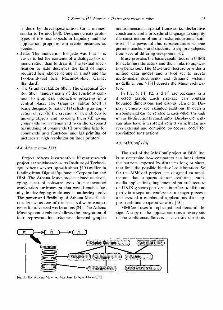
Muse provides the basic capabilities of a UIMS for defining interactors and their links to applica- tion behaviour. The Muse architecture provides a unified data model and a tool set to create multi-media documents and dynamic systems modelling. Fig. 5 [31] depicts the Muse architec- ture.
In Fig. 5, P1, P2, and P3 are packages in a directed graph. Each package can contain bounded dimensions and display elements. Dis- play elements are assigned positions through a mapping and can be related to each other through uni or bi-directional constraints. Display elements can also have interpreted scripts (which can ac- cess external and compiled procedural code) for specialized user actions.
4.5. MMCon f [131
The goal of the MMConf project at BBN Inc. is to determine how computers can break down the barriers imposed by distances long or short, that limit the possible kinds of collaboration. So far the MMConf project has designed an archi- tecture that supports shared, real-time multi- media applications, implemented an architecturc on UNIX systems partly as a interface toolkit and partly in a separate conference manager process, and created a number of applications that sup- port real-time cooperative work [13].
MMConf uses a replicated architectural de- sign. A copy of the application runs at every site in the conference. Servers at each site distribute
Fig. 5. The Athena Muse Architecture (adapted from [31]).

48 S. Rathnam, M.V. Mannino / The human-computer interface
input to each copy using a propagation control mechanism to ensure that every copy sees the same sequence of input events. Output from each copy only appears locally; because all copies see the same input, their states remain synchronized, yielding identical output at each site. The MM- Conf architecture has five parts: • Conference management and communications. • An application programming model. • A method of intercepting input to applications. • Window-system-specific implementations of the
programming model. • A mapping between window-system-specific in-
put events and MMConf generic event descrip- tions. The UNIX implementation of MMConf puts
everything but the conference management and communications system in a user interface toolkit. The toolkit is linked with the tele-conferencing applications. Conference management resides in a separate process.
The tools developed include the B B N / S l a t e document editor. This tool lets users view and edit documents containing text, graphics, images, spreadsheets, and voice. A second tool that has been developed is ViewShell - a terminal emula- tor. The third tool is a Video Information Server. The fourth tool is Sketch - a simple shared graphical editor that functions without floor con- trol. The fifth tool is Presenter which implements a slide show in a tele-conference.
4.6. Suite [16,17]
Suite began as a tool to aid the development of single-user systems and has since evolved to support the development of multi-user interfaces. Suite [16] offers several advanced features miss- ing from contemporary interactive systems includ- ing a generic direct-manipulation user interface; a flexible input model offering the benefits of incremental and delayed feedback, customizable system-provided dialogue managers, loose physi- cal coupling between an application and its dia- logue manager.
Suite which has been developed at Purdue University, is currently implemented on a net- work of workstations executing Unix, T C P / I P , X, and Sun NFS. It uses X for displaying win- dows and T C P / I P and NFS for communication
among and naming of applications and dialogue managers. Suite provides an object layer support- ing distributed and persistent objects. Suite pro- vides an inheritance model, using multiple inter- secting hierarchies based on the IS-A and IS- PART-OF primitives, for reducing the effort re- quired to specify user interface properties or at- tributes of active values. Grouping of attributes is allowed and the dependency maintained auto- matically.
The Suite single-user primitives are built around the abstractions of active variables, at- tributes, and value groups. An active variable is an application data structure displayed to the user that can be updated by the application to show results and edited by the user to input new values. An attribute is an interaction property of an active variable. A value group is a group of related active values that stores attributes shared by these values. Suite primitives are divided into Suite calls, which are invoked by applications to perform interface operations and Suite callbacks (procedures invoked in applications in response to user actions). The Suite calls consist mainly of: (i) Crea t ion /Dele t ion calls to c r ea t e /de l e t e dis- plays of active variables (ii) Attribute Set t ing/ Retrieving calls which define and retrieve the value of an attribute in a value group (iii) Value Set t ing/Retr ieving calls which update and re- trieve the value of an active variable and (iv) Message calls which displays text messages to users.
Suite has been extended, through a set of primitives, to support the development of multi- user interfaces [17]. These primitives support both col labora t ion- t ransparent and collaboration- aware multi-user programs. Additionally they al- low existing single-user programs to be incremen- tally changed to their multi-user counter-parts. The collaboration-aware primitives include those for tailoring the input and output to a user, authenticating users, executing code in a user's environment and querying and setting properties of it, and tailoring the user interface coupling. The extended set of Suite primitives includes methods for: • Supporting collaboration transparency. • Supporting collaboration awareness through
group awareness. • Supporting collaboration awareness through
user /sess ion awareness.

S. Rathnam, M.V. Mannino / The human-computer interface 49
• Supporting collaboration environment awareness.
• Supporting collaboration coupling awareness
awareness through
awareness through
5. Advanced interfaces of DSSs 13
The advent of direct manipulation interfaces has changed the role of DSSs themselves. Angehrn and Luthi [1] describe this shift as:
"In traditional approaches the focus is on deter- mining a-priori the functionality presumably needed by the decision maker and embedding it into the system. The user-centred approach aims at design- ing a flexible, usable working environment the user can interact with effectively"
In the previous two sections, we described the underlying theory of UIMS and reviewed a set of tools that are available to the developers of DSSs. While most DSSs are not built using UIMS tech- nology, there is evidence that the use of UIMSs (or other high level tools) is gaining acceptance. In this section, we describe a representative set of DSSs with advanced user interfaces highlighting their unique features and relationships with UIMS formalisms and tools. We focus on answer- ing the three inter-related questions: (i) What are the unique DSS interface requirements? (ii) How have interface formalisms have been used in DSS interfaces? and (iii) What has been the use of UIMS in DSS interfaces?.
To answer the preceding three question we now examine the GT-MOCA system developed by Chu et al. [12], Tolomeo developed by Angehrn and Luthi [1], Max developed by Kimbrough et al. [43], and Networks developed by Jones [36,37].
satellite ground control operators working at the NASA Goddard Space Flight Center, Greenbelt MD. GT-MOCA provides users tools for task and information management and system visualiza- tion. The GT-MOCA interface was developed using TAE Plus and the X toolkit as UIMSs and runs on a dual-monitor Sun SparcStation envi- ronment. GT-MOCA runs as a client program that is served by a simulation environment an d communicate with the simulation via T C P / I P .
Like Max, and unlike Tolomeo and Networks, GT-MOCA is designed to support specialized tasks. GT-MOCA is designed to support analysts responsible for the configuration and verification of the communication link between an unmanned scientific satellite and the ground equipment that captures and processes its data. The analysts also monitor spacecraft data, command the space- craft, and keep records of all relevant actions and system events.
The basic metaphor used for supporting task management is that of a blackboard. The black- board appears as a panel containing buttons (but- tons can call up other panels) and explanation boxes. The blackboard depicts the current state of the system as well as the set of possible func- tions, tasks, and actions that a user can perform. As actions are executed they get added to the blackboard and the linkages with tasks in progress get established. Actions performed by the system are coded in blue and actions performed by the operator in white. The currently selected opera- tion is coded in yellow. The main panel in the interface was implemented using TAE while the nodes and labels which represent action elements are implemented as X widgets (for efficiency). Links are drawn using the lowest possible level - the X function XdrawLine. Fig. 6 depicts a sketch of the blackboard.
5.1. GT-MOCA: the georgia tech mission opera- tions cooperative assistant [12,39,40]
The Georgia Tech Mission Operations Coop- erative Assistant (GT-MOCA) [12,39,40] is a model based computer associate for experienced
~3 The description of each of these systems is adopted and condensed from the full paper which is cited in the sub- section heading. The reader is referred to that reference for more detail.
Configure ) Functions A P ~ ' ~
Subfunctions CConfigure ( " (~CcCcnfigure TAC)
I I
Fig. 6. A sketch of the blackboard used to support task management in GT-MOCA (adapted from [12]).

50 S. Rathnam, M.V. Mannino / The human-computer interface
Information management is supported through the use of organized, color-coded textlist items on a panel. Each textlist corresponds to a different kind of communicative act. Messages are gener- ated dynamically based on system and user-gen- erated events. As messages get generated the textlists get updated asynchronously. Message / communication objects also maintain status infor- mation about the set of actions that have been performed and can be performed on the object. Since the tool is designed to support real-time decision making, the mechanism to notify users of alerts (a special kind of communicative act) is of special interest. In GT-MOCA, color is used to highlight categories of communicative acts with alerts being coded in red.
5.2. Tolomeo [1]
In a recent award winning paper Angehrn and Luthi [1] describe Tolomeo - a DSS for decision making in a geographic context. An exemplar application is the analysis of a communications networks in which the nodes represent stations and links represent transmission channels. Tolo- meo marks a significant shift in the design of DSS interfaces for two reasons. First, its design is user-centred - the need to make the human-com- puter interaction process (as opposed to the mod- elling tools and analysis techniques) the focal point of the finished application. Second, by pro- viding a visual modelling environment, it suggests new ways for matching the technical world of information processing with individual ap- proaches to problem solving.
Tolomeo represents an intersection of visual languages and OO modelling. The design of Tolomeo is based on three primitives: Objects (which could be either concrete or abstract) and attributes, Relations (which describe the struc- tural or functional dependencies between other objects) and Constraints (similar to those de- scribed in section 3.5). These three generic primi- tives are available to users in a visual interactive environment. Users incrementally describe differ- ent decision situations and solution alternatives by introducing and directly manipulating objects.
Tolomeo supports end-user modelling through incremental specification, visual modelling and the integration of analysis tools. Users incremen- tally describe different decision situations and
solution alternatives by directly manipulating ob- jects. Users can begin with a simple situation and gradually add complexity. All operations are per- formed incrementally and experimentation with various decision alternatives are possible at each stage. Models in Tolomeo are visually con- structed using objects that have a close fit with the direct manipulation interface. Users can spec- ify the display and interaction properties of ob- jects as they construct models. Tolomeo smoothly integrates supporting analysis tools using a mod- elling-by-example scheme. A user dynamically formulates a suggestion which is interpreted by Tolomeo based on past behaviour. Supporting analysis tools are automatically executed based on the context of the request. The ad-hoc appli- cation of different techniques is also supported.
Constraint modelling is an underlying formal- ism of Tolomeo. Toiomeo supports reactive be- haviour through a system of automatic recalcula- tions (like a spread-sheet) and constraints. Con- straints in Tolomeo ensure that the structural and semantic properties of the interface stay consis- tent with the properties of the model (e.g. the value of an attribute is always less than a constant or a new switching center can only be added at an existing city).
5.3. Max I431
In another recent award winning paper Kim- brough et al. [43] describe Max - a Hypertext based DSS shell or environment originally de- signed to support ship acquisition for the U.S. Coast Guard. Like Tolomeo, and Networks, the Max approach to producing a high quality user interface for DSS is based on using a user inter- face technology (generalized hypertext) that maps directly to the theoretical basis for the design of the problem-processing and knowledge process- ing sub-systems. Max is designed in two levels. Level 1 of Max is a document oriented DSS that provides document and model management. Level 2 of Max incorporates a task-activity model that supports the process of decision making.
A major focus of Max is to represent the relationship between models and their artifacts using a document orientation. All primitive ob- jects available to a user are represented and manipulated as documents. Max is designed to be consistent with argumentation theory which re-

S. Rathnam, M.V. Mannino / The human-computer interface 51
quires a DSS to support the examination of premises and arguments or the assumptions be- hind the artifacts presented as output. Max sup- ports different browsers (alternative interfaces) for analysts and executives. Analysts execute models under various decision scenarios to create documents which in turn can be used by execu- tives.
Because of their complexity, documents are organized in a hypertext fashion. The generalized hypertext nature of Max allows users to dynami- cally create nodes (documents) and links. The browser serves as both an authoring tool as well as a reading tool. All the objects in the Max domain can form nodes and links in a generalized hypertext network. The high level linkage be- tween data and model elements through a hyper- text model provides consistency of interaction across a broad range of applications and skill levels.
The analysis tools and techniques are inte- grated using a model management component named TEF A (The Eileen Ford Agency because model management is so fashionable). TEFA supports a modelling life cycle which includes identification of the model paradigm, formulation and specification of a particular model (using a declarative approach), implementation of the model, determination of parameter values, solu- tion of the model, use of the model, and re-de- sign of the model. An extended work breakdown structure underlies modelling life cycle support in TEFA.
5.4. Networks [36,37]
cations reported have included transportation problems, decision tree problems, travelling sales- man problems and scheduling problems.
In Networks both the graphs themselves and operations defined on them are specified as graphs. Networks allows users to design and de- velop DSSs using graph-based modelling [36]. The set of permissible interface-level events that a user can generate a n d / o r receive are specified through the production rules of a graph grammar. Assuming that the production rules are appropri- ately specified, the graph produced will satisfy the characteristics of the desired model [38]. The use of graph grammars to model the dialogue process between a user and a DSS can be seen as an extension of the use of formal languages as a basis for UIMS design. Graph grammars are Tur- ing-complete which implies that they are general, powerful, formal and executable [38].
In Networks the linkages between the be- haviour of an application and a set of interface events is supported by the use of syntax-directed editing [60]. The output of Networks is a syntax- directed editor for a particular category of prob- lems. Users can manipulate the models in the DSS using the set of customized productions de- fined by the semantics of the syntax-directed edi- tor. The use of syntax-directed editing to specify interface events ensures that the dialogue be- tween the user and the DSS is always syntacti- cally valid. This obliviates the need (from a DSS developer's point of view) of having to ensure that the semantic properties of the interface and application are consistent in the presence of syn- tactic errors.
Of all the work that has been done at the intersection of DSS and UIMS the work of Jones [36,37] has the highest level of semantic coupling and macro-communication between the interface and the application functionality. Jones [36,37] has designed an editor generator - Networks - which provides a tool to manipulate attributed graphs and generate direct manipulation inter- faces. In an attributed graph the nodes and links have attributes of a specified type. The values of the attributes can be derived in terms of at- tributes of other objects in the graph much like a spreadsheet. Several extensions to the original graph grammar ideas and DSS applications have been incorporated in Networks [37,38]. The appli-
6. Issues: caveats when using UIMS to develop the interface component of a DSS
In this section we discuss requirements of DSSs and relate them to characteristics of UIMS tech- nology. While UIMSs offer a powerful technolog- ical solution to the problems of delivering higher quality interfaces at a lower cost, several caveats are in order before they can be used in a DSS context. To help map current UIMS technology to the interface requirements of industrial strength DSSs, we raise a set of issues that need to be addressed in using UIMS for building the

52 S. Rathnam, M. E Mannino / The human-computer interface
interface component of a DSS (and may conse- quently lead to extensions of UIMS technology).
6.1. Issue 1 - closer linkages between application functionality and interface
In a DSS context it is important to ensure that the right kinds of coupling mechanisms (hooks) for communicating information between the in- terface and the application functionality exist. Developing interfaces for complex DSS applica- tions can require the use of several or even com- posite metaphors [10] as part of the interface design strategy. Furthermore, in the many DSS applications in which there is a great deal of dialogue the interface code must have extensive access to the state and actions of the application system [21]. For example, while a UIMS might make the task of manipulating windows in a multi-window, multi-tasking environment simple, it is still up to an underlying DSS application to ensure that the contents of and the behaviour in each of the windows is valid syntactically and semantically.
UIMSs, by definition do not provide applica- tion functionality. For example, Networks itself does not incorporate any graph-theory based al- gorithms. Rather, it provides hooks to external solvers. An inappropriate level of coupling be- tween the application functionality and interface can exacerbate the basic problem in using UIMS - of ensuring that the programming interface is reasonable [62]. The lack of attention to the issue of coupling can raise the complexity of applica- tion development to the point that it negates the advantages of using a UIMS.
Correctly connecting the dialogue to the appli- cation (i.e. coupling) is difficult because an ideal separation is "hard to define and even harder to achieve" [62]. Effective coupling requires balanc- ing the communication overheads, level of dia- logue independence and semantic-feedback. Cou- pling can be accomplished by either building more knowledge about application semantics into the interface (the macro communication approach) or
by establishing closer communication between the interface and the application semantics (the mi- cro communication approach). In practice, a com- bination of approaches is required (because mi- cro communication yields a cleaner separation and macro communication requires less over- head) but often overlooked [62].
As a first step towards developing systems that support a mixed approach, several frameworks are under investigation as replacements for the Seeheim model (which proposed a narrow chan- nel between the application and dialogue control). One of these frameworks [70] proposes sharing application information to support semantic feed- back (Fig. 7).
The Seeheim model (and UIMSs based on it) promote narrow (infrequent) coarse-grained com- munication between the interface and functional- ity. Such a communication model is effective for textual interfaces but highly inappropriate for direct-manipulation interfaces. On the other hand, UIMSs based on the Szekely framework explicitly recognize the need for communication between the functionality and interface compo- nents of an application. By incorporating a se- mantic support component that lies between the dialogue and presentation control, and the appli- cation the Szekely framework allows information sharing and at the same time preserves modular- ization.
One of the efforts being made to develop a UIMS that supports high level interface design descriptions and provides a powerful coupling mechanism between application functionality and the interface lies in using knowledge-based HCI [21] as operationalized in the UIDE system [23]. UIDE uses a knowledge base to store a concep- tual design of application objects and provides for an OO model of the interface. Consistency is facilitated by the specification of pre and post- conditions. These specification mechanisms in UIDE allows the high-level specification of the mapping between interface events and applica- tion semantics. UIDE requires less low-level in- formation and more high-level information (from
presentation support control component
Fig. 7. The Szekely framework for interaction modelling.
Application

S. Rathnam, M.V. Mannino / The human-computer interface 53
a quantity perspective) to flow between the inter- face and the application functionality.
6.2. Issue 2 - incorporating multiple media into the human-computer interaction process
Communication media vary in their capacity to process the richness of information where infor- mation richness is defined as the ability of infor- mation to change under standing within a time interval [14]. Different "genres of communication" (rules and regulations, formal information sys- tems, special reports, planning, direct contact, integrator, group meetings) support structural mechanisms that fit along a continuum with re- spect to their capacity for reducing uncertainty or resolving equivocality for decision makers [14]. Similarly, McLuhan [46] has argued that the speed and nature of the dominant communication medium severely impacts and even possibly cre- ates social forms. He writes:
"It is the medium that shapes and controls the scale and form of human association. The effects of communication technology do not occur at the level of opinions or concepts, but instead alter the sense ratios or patterns of perception. Media are active metaphors in their power to translate experi- ence into new forms of learning."
Progress in hardware and software has facili- tated interactive access to digital multimedia in- formation [24]. Given the inexorable trend to- wards the use of multi-media in computing, the issue of incorporating multi-media into the inter- face for a DSS arises. The use of multi-media presents four challenges for developers of DSSs. First, multi-media hardware and software are of- ten special-purpose, incompatible across a range of platforms and expensive. Second, in large-scale applications integration rather than just use of multiple media is the overriding design issue. Third, there are no clear theoretical guidelines or empirical results available on how decision mak- ers would use multi-media information. Fourth and most important, continuous media such as audio and video introduce the need for explicit synchronization with non-interface (i.e. events at the application level) events. For example, users might have to be notified of critical values through sound alerts.
6.3. Issue 3 - automatic presentation of output
Deep knowledge about appropriate output for- mats for standardized data types is absent in the mechanisms provided by most user interface de- velopment tools in general and UIMS in particu- lar. While systems like Max and Tolomeo are good for visual modelling, they breakdown when there is the simultaneous need for model visual- ization. Supporting visual modelling and model visualization simultaneously is critical as current DSSs are often utilized in highly interactive con- texts in which the output is represented graphi- cally. DSSs are moving from algorithm manipula- tion to direct manipulation, from traditional data processing to visual information processing, and from problem solvers to context-sensitive mod- elling environments [1]. For example, if a Linear Program is used as the underlying model then the output of the sensitivity analysis can be depicted graphically.
Paralleling the need for and the use of sophis- ticated interfaces has been the knowledge gained through systematic laboratory experiments on the effects of presentation format on managerial de- cision making. These experiments have generated theory-based guidelines for the design of the in- terface component of a DSS [35]. Typical of such empirical results [3] are: • Changes in representation increase decision
time but have no effect on performance. • The influence of presentation format on per-
formance depends on task; color has some pos- itive but no detrimental effects.
• Presentation format influences information ac- quisition strategies; presentation format and task requirements jointly influence evaluation strategies. The work done by Mackinlay [45] provides a
start on providing meaningful representations for output when its nature is known. Mackinlay's work develops an application independent pre- sentation tool (APT) that automatically designs effective graphical presentations of information stored in a relational form (like an SQL table). The fundamental approach used in APT is to automatically extract data, synthesize it and then render it as an image. Both expressiveness crite- ria (whether a graphical language can express the desired information) and effectiveness criteria (whether a graphical language exploits the capa-

54 S. Rathnam, M.V. Mannino / The human-computer interface
bilities of the human-computer interaction envi- ronment) are represented in APT. The approach used by Mackinlay is similar to the work of Jones in that output presentations can be described as sentences of a formal graphical language. Besides providing the primitives required to display data elements, mechanisms to generate output for data generated through composition and other rela- tional operations are provided.
6.4. Issue 4 - developing multi-user interfaces
Decision support systems often need to be used by a group of people [15]. This forces the developers of the interface component of a DSS to think in terms of developing multi-user inter- faces and groupware applications. Groupware as defined by Ellis, Gibbs, and Rein (1989) is: "A class o f applications, arising from the merger of computation and communication, that support two or more users engaged in a common task and provide the users with an interface to a shared environment." Multi-user systems are formally defined using a triplet of definitions [74]:
• Definition 1: A system is a collection of related components, as perceived (or abstracted) by an external viewer; a system has an environ- ment, that consists of components related to those making up the system, but external to the system itself; part of the system description (or specifica- tion) will be an explicit expression of how and in what way components are related. Formally a system is a 3-tuple of components, relationships and (at least one, but possibly more) systemic propert ies System:: = = (C,1LP).
• Definition 2: A multi-system is a collection of related systems, again as perceived (or ab- stracted) by an external viewer; the systems may (but do not always) have common components, but either through such commonality, or in more abstract terms, an explicit specification will ex- press how and in what way systems are related.
• Definition 3: An interface is the formal ex- pression of the relationship between a system and its environment, or between the systems of a multi-system, as defined by the external user.
Multi-user interfaces for a multi-person DSS are qualitatively different from those designed for single user DSS ~4. For example, the semantics of
14 Note that by definition, a multi-user interface implies a multi-person system.
complex operations like undo are hard to define precisely and equitably. In multi-user interfaces to DSS the key issues are the equality of interac- tion between individuals and focus of attention for an individual. In multi-user interfaces the presence of multiple discussion threads makes floor control issues complicated. Multi-user inter- faces also require the support for history and change management in the interface - especially when the underlying models are used in a plan- ning period.
In multi-user interfaces, concurrency control and coordination among the users' actions are required at several levels of abstraction, For ex- ample, coordination of users' actions needs to be carried out at the user interface level by having weak locking mechanisms such as telepointers (a cursor that appears on more than one display and that can be moved by different users) and floor passing conventions. Further, as several individu- als work on the same problem it becomes neces- sary to provide an explicit notification and update schema, which keeps the users of the DSS up to date by providing automatic feedback. ~5
The relaxed WYSIWIS (what you see is what I see) model, developed for COLAB, is one that has been used successfully as an interface guide- line to address the issues involved in developing multi-user interfaces [68]. Relaxed WYSIWIS re- laxes the constraints imposed by strict WYSIWIS on four dimensions: display space (the set of display objects to which WYSIWIS is applied), time of display (when displays are synchronized), subgroup population (the set of participants in- volved or affected) and view congruence (the visual congruence of displayed information).
It still remains to be seen how support for strict WYSIWIS or relaxed WYSIWIS will be incorporated into UIMS. Currently, the technolo-
15 GROVE [20] provides explicit notification at the interface level through the use of real time animation. For example, text is "aged" so that recently entered text appears in bright blue and then gradually changes to black. While modifications are immediately visible to the person who initiates them, they are indicated on other users' displays by the appearance of "clouds" over the original text. The position and size of a cloud indicates the approximate location and extent of the modification. When the non-ini- tiating user has stopped typing for some time, his/her clouds disappear and the new text is displayed, first in blue and gradually changing to black.

s. Rathnam, M.V. Mannino / The human-computer interface 55
gies in this area have taken on the roles of supporting conferencing with multi-media inter- action in real time. We see the need to focus on the issue of developing the characteristics of good multi-user interfaces and the tools that will sup- port their building.
6.5. Issue 5 - better support for interface evalua- tion
We do not see too many efforts to test the hypothesis that a UIMS improves the productivity of users and developers when the system involves complex interactions. UIMS prototypes do not test whether the specified interface met the re- quirements of the user 's tasks [19]. This has re- sulted in the lack of mechanisms for evaluating the quality of the interface that has been built. Interface design (in both the DSS and general contexts) is an iterative process which seeks to overcome the 5 following gaps [71]: • Ecological gap: The gap between results ob-
tained in a laboratory setting and the real-world results.
• User gap: The gap caused by individual differ- ences and levels of motivation.
• Task gap: The gap caused by generalizing across tasks and problem formulation.
• Artifact gap: The gap caused by the use of several levels of a computing environment and the gaps between short- term and long-term use.
• Work-context gap: The gaps caused by differ- ing job contexts, social contexts and cultural contexts. While usability testing (the most frequently
used way of determining interface quality) is nec- essary it is rarely sufficient.
Supporting rich, context-filled evaluation of in- terface quality requires the collection of precise data. This requirement flies in the face of what UIMSs provide by way of tools and techniques to collect data on the human-computer interaction process. It would be useful to automatically col- lect interaction information from a static (error rates, etc.) as well as a process (interaction pat- tern) standpoint - or as Yogi Bera put it: "you can observe a lot by just watching". This would help designers easily refine interfaces. Major re- writes of code will not have to be done every time new models of interaction are discovered. The
Garnet system [53] is the first systematic at tempt to address this issue.
6.6. Issue 6 - software integration and standards
One of the greatest advantages of the Macin- tosh Toolbox was that the primitive routines were part of the underlying operating system. This along with the use of a consistent imaging model (QuickDraw) enabled the user-interface to work efficiently even on a low-end micro-processor. While CPU speeds are no longer a very signifi- cant issue, a DSS requires high performance in terms of interface response time (i.e. the time required to translate and communicate an inter- face event to the application functionality). Incor- porating graphics primitives at the operating sys- tem level can provide the technological platform to increase the responsiveness of the user inter- face across applications. As a panel discussion at the ACM conference on user interface technol- ogy [72] noted:
"The basics o f an operating system include man- agement o f processing time, memory, inter-process communication, and persistent storage. Choices made in the proL, ision of these sert~ices can impact the user interface, ecen when many layers intercede."
Response time is still an important concern for highly interactive DSS applications that run on low-end micro-processor based systems. As the experience with G T - M O C A seems to indicate, developing interfaces using UIMSs (as opposed to a low level tool like the Macintosh Toolbox or the X toolkit) can increase the response time and application size by an order of magnitude as several extra layers of software between the user interface and the low-level primitives are intro- duced.
In developing an industrial DSS, a UIMS should be an integrated part of a suite of applica- tion development tools. The development of UIMS for mainly LISP or X environments re- duces their viability for use in a DSS context as most DSS systems are not built in either of these environments. Developers of UIMSs for DSS ap- plications will have to address the issues of inte- grating the development tools into the larger software development environment. Further-
56 S. Rathnam, M.V. Mannino / The human-computer interface
more, the arena of desktop GUIs, which forms the management interface for many DSS applica- tions, is marked by tremendous confusion and conflicting commercial claims. As was recently quoted (Byte July 1989 p.250):
"Back then (1984) genealogy was straightforward: Researchers at Xerox's Palo Alto Research Center begat the Xerox Star; Steve Jobs visited PARC, saw the Star, went back to Apple, and begat the Mac. But five years later, the begats have become bewil- dering. The Mac begat Windows - or was it a cousin? Windows begat the Presentation Manager - which doesn't look much like the Mac at all, thanks to IBM, which begat Systems Application Architec- ture (SAA). M I T begat X Window, which crossbred with PM and New Wave to give birth to Motif. Tandy begat DeskMate, Japan Inc., begat BTRON, Steve Jobs - back again for a second try - begat NextStep, and Apple has filed a paternity suit against Microsoft. What a mess."
In an age in which software standards, particu- larly in the GUI area, are being rapidly defined (and re-defined) it becomes necessary to be able to design and develop systems using a set of software tools that conform to commonly ac- cepted standards (e.g. Motif). We are currently witnessing four major alternatives in terms of a hardware/software environment for developing DSSs. The outcome of the workstation-Unix, PC-Microsoft Windows, Macintosh and PS/2- OS2 wars could have significant repercussions in terms of a basic development environment for DSSs. Using UIMS to develop interfaces pro- motes standardization across applications and even hardware platforms. UIMS facilitate stand- ardization by providing a software layer in be- tween the design of the interface and its realiza- tion under a specific windowing system.
Interestingly we see two directions in terms of the UIMS and standardization debate. The first direction is to produce the same interface irre- spective of the underlying hardware/software in- frastructure. X based tools and the Motif stand- ard encourage this "open systems" approach in which the end-user interfaces are standardized but the programming interfaces are specialized. The second (and diametrically opposite) direction has been adopted by SmaUtalk systems (notably Smalltalk/V and its derivatives). The Smalltalk
approach has been to standardize the program: ming interface (and its semantics) but to let the end-user interface be customized to the hard- ware/software environment. The X approach has the advantage of consistency at the overhead of having an extra layer of software.
7. Conclusions
While DSSs have never been easier to use, the development of their interfaces has never been more difficult. Just as the last revolution was for people who used computers, there needs to be one for people who design and build human-com- puter interfaces. The rapid development of user interfaces for DSSs of complex application func- tionality is an important unresolved issue [32]. UIMSs seem to be the tools for addressing this problem by supporting, through the entire life- cycle, the development of the interface portion of a DSS. UIMS provide programming interfaces for tasks as diverse as menu creation, form creation, the generation of user interface objects such as controls and dialogues, text and graphics han- dling, and event-based programming. This is be- cause UIMSs facilitate software reuse, provide powerful programming interfaces, support a wide-variety of interaction styles and provide a high-level model of the human-computer interac- tion process.
While Tolomeo, Max and Networks are suc- cessful in providing an integrated decision sup- port system, many of their features could have been more easily implemented with a tool like Athena Muse or Intermedia [76]. Both Athena Muse and Intermedia provide all the primitives required to support generalized multi-user hyper- media capabilities. In our opinion the effort re- quired to produce the user interface for systems like Max could have been significantly reduced with a UIMS. UIMS based on X technology afford the advantage of rapid interface develop- ment in a client-server environment. Besides in- terface development, X based tools facilitate the development of applications in which the inter- face and functionality process need to communi- cate across a network (in a distributed or client- server fashion).
Unfortunately, the use of UIMS in a DSS context has been restricted. Indeed much of the

S. Rathnam, M.V. Mannb~o / The human-computer interface 57
UIMS work has p roceeded "outside the main- stream of MIS, DSS, and ESS" [32]. Despi te their
many advantages, UIMSs have not yet emerged as practical deve lopment tools that can be used on a widespread basis for three reasons [49]: • The i r p rog ramming interfaces tend to be pro-
cedural ra ther than declarative. • The b ind ing be tween the interface and the
appl icat ion funct ional i ty is of ten weak. UIMSs do not directly suppor t all the high-level inter- face descript ions requi red to develop complex DSSs which use opt imizat ion and s imula t ion
• The separa t ion of interface from appl icat ion
funct ional i ty is unconven t iona l from the point of view of commercia l development . Besides the unconven t iona l na tu re of the separat ion, U I M S tend to drive p rogrammers to adopt a design strategy that is user-centred. Very often using an U I M S requires the p rog rammer to def ine the interface first and then design the algori thms and functionali ty. There is an in- buil t resis tance to change.
In conclusion, as Kasik et al. [42] state from their initial exper iments on the viability of U I M S technology:
• A UIMS is an effective tool that is only neces- sary but not sufficient to define a development environment for highly interactive applications. Graphics and database tools are needed to comple- ment the UIMS.
• A UIMS must be able to complex dialogue specifications that are part of the real world. Un- fortunately, many UIMS implementations are good at handling simple situations but not complex ones.
• There are benefits to using a UIMS from both a development and usage standpoint.
• UIMS technology should not be viewed as a universal tool, but when applied properly it can be viewed as an excellent addition to the basic set of required development tools.
We find that the use of U I M S to develop the interface componen t of a DSS is still p remature . Wi thou t a unifying theoret ical basis or widely accepted s tandards , they will r ema in in a state of confus ion for some time - with more and more products be ing developed but be ing used to lesser and lesser degrees. As the following sober ing extract from a CHI '88 pane l discussion [11] warns:
"As long as the art o f interface design is rapidly advancing, we should not expect UIMSs to support the most advanced interfaces. As seductive as it is, the dream of being able to separate out interface development and application development is a false one. Direct Manipulation tasks, and their data vary too much. The specification of such complex be- haviour will require some form of programming or the other."
References
[1] A. Angehrn and H. Luthi, Intelligent Decision Support Systems: A Visual Interactive Approach, INTERFACES, Vol. 20 No. 6, Nov-Dec 1990, pp. 17-28.
[2] P.S. Barth, An Object Oriented Approach to Graphical Interfaces, ACM Transactions On Graphics, Vol. 5 No. 2, pp. 142-172, 1986.
[3] I. Benbasat and B.R. Nault, An Evaluation of Empirical Research in Managerial Support Systems, Decision Sup- port Systems, Vol. 6 1990, pp. 203-226.
[4] J.L. Bennett, Analysis and Design of the User Interface for Decision Support Systems, in Building Decision Sup- port Systems, Bennett, J.L., (ed), Addison Wesley Pub- lishing Co., Reading MA.
[5] R.H, Bonczek, C. Holsapple and A.B. Whinston, Foun- dations of Decision Support Systems, Academic Press, New York, 1981.
[6] P. Bono, J. Encarnacao, F. Hopgood and P. ten Hagen, GKS: The First Graphics Standard, IEEE Computer, 9 (23), July 1982.
[7] Borland International Inc., Turbo Pascal For Windows: Programmer's Guide, Scotts Valley, CA: Borland Inter- national, Inc.
[8] A. Borning and R. Duisberg, Constraint-Based Tools for Building User Interfaces, ACM Transactions On Graph- ics, Vol. 5 No. 4, pp. 345-374, 1986.
[9] M.D. Brown, Understanding PHIGS, TEMPLATE, The Software Division of Megatek, 1985
[10] J.M. Caroll, R.L. Mack and W.A. Kellogg Interface Metaphors and User Interface Design, Research Report RC 13400 (#59681) 12/4/87, User Interface Institute, IBM T.J. Watson Research Institute, Yorktown Heights. NY.
[11] CHI 1988, U1MSs: Threats or Menace?, Panel Discus- sion, CHI '88 Proceedings, pp. 197-200.
[12] R.W. Chu, P.M. Jones, W.M. Harris and C.M. Mitchell, GT-VITA and GT-MOCA: More Experiences Using TAE Plus, Proceedings of the 9th TAE Users Confer- ence, Greenbelt, MD, Nov. 1991, pp. 211-225.
[13] T. Crowley, P. Milazzo, E. Baker, H. Forsdick and R. Tomlinson, MMConf: An infrastructure for building shared multimedia applications, Proceedings of the CSCW '90 Conference, Los Angeles October 1990. pp 329-343.

58 S. Rathnam, M.V. Mannino / The human-computer interface
[14] R.L. Daft and R.H. Lengel, Organizational Information Requirements, Media Richness and Structural Design, Management Science, Vol. 32 No. 5, pp 554-571.
[15] A. Dennis, J. George, L. Jessup, J. Nur~amaker and D. Vogel, Information Technology to Support Electronic Meetings, MIS Quarterly, December 1988.
[16] P. Dewan, A Tour of the Suite User Interface Software, Proceedings of the ACM SIGGRAPH Symposium on User Interface Software and Technology, Snowbird Utah, Oct 3-5, 1990, pp. 57-65.
[17] P. Dewan and R. Choudhary,, Primitives for Program- ming Multi-user Interfaces, Working paper, Department of Computer Science, Purdue University 1991.
[18] Digitalk Inc. Smalltalk/V Windows: Tutorial and Pro- gramming Handbook, Digitalk Inc., 1991.
[19] D.A. Duce, M.R. Gomes, F.R.A. Hopgood and J.R. Lee, (eds) User Interface Management and Design, Springer- Verlag, New York, 1991.
[20] CA. Ellis, S.J. Gibbs and G.L. Rein, Groupware: The Research and Development Issues, MCC Technical Re- port # STP-414-88, March 3 1989.
[21] G. Fischer, Human-Computer Interaction Software: Lessons Learned, Challenges Ahead, IEEE Software, Vol. 6 No. 1, 1989, pp 44-52.
[22] J. Foley and A. Van Dam, Fundamentals of Interactive Computer Graphics, Addison-Wesley, 1982.
[23] J. Foley, W.C. Kim, S. Kovacevic and K. Murray, Defin- ing Interfaces at a High Level of Abstraction, IEEE Software, Vol. 6 No. 1, 1989, pp 25-32.
[24] E.A. Fox, Advances in Interactive Digital Multimedia Systems, IEEE Computer, October 1991, pp. 9-17.
[25] A. Goldberg, Smalltalk-80: The Interactive Programming Environment, Addison-Wesley, Reading MA, 1984.
[26] M. Green, A Survey of Three Dialogue Models, ACM Transactions On Graphics, Vol. 5 No. 3, pp 244-282, 1986.
[27] J. Grudin, The Case Against User Interface Consistency, Communications of the ACM, Vol. 32 No. 5, Oct. 1989, pp 287-299.
[28] D. Harel, On Visual Formalisms, Technical Report CMU-CS-87-126 June 5, 1987.
[29] D.A. Henderson and S.K. Card, Rooms: The Use of Multiple Virtual Workspaces to Reduce Space Con- tention in a Window-Based Graphical User Interface, ACM Transactions On Graphics, Vol. 5. No. 3, pp. 211-243, 1986.
[30] D. Hix, Generations of User-lnterface Management Sys- tems, IEEE Software, September 1990. pp 77-87.
[31] M.E. Hodges, R.M. Sasnett and M.S. Ackerman, A Con- struction Set for Multimedia Applications, IEEE Soft- ware, Vol. 6 No. 1, 1989, pp 37-43.
[32] C. Holsapple, S. Park and A.B. Whinston, Framework for DSS Interface Development, Proceedings of the NATO ASI on Recent Development in DSS, II Cioccio, Italy, June 1992.
[33] R.C. Holt, T. Stanhope and G. Lausman, Object Ori- ented Computing: Looking Ahead to the Year 2000, IBM TR-74.060, IBM Canada Laboratory, April 1991.
[34] R.J.K. Jacob, A Specification Language for Direct- Manipulation User Interfaces, ACM Transactions On Graphics Vol. 5 No. 4, pp. 283-317, 1986.
[35] S.L. Jarvenpaa and G.W. Dickson, Graphics and Man- agerial Decision Making: Research Based Guidelines, Communications of the ACM, Vol. 31 No. 6, 1988, pp 764-774.
[36] C.V. Jones, An Introduction to Graph-Based Modelling Systems, Part I: Overview, ORSA Journal of Computing, Vol. 2 No. 2, 1990.
[37] C.V. Jones, An Introduction to Graph-Based Modelling Systems, Part II: Graph Grammars and The Implementa- tion, ORSA Journal of Computing, Vol. 3 No. 3, 1991.
[38] C.V. Jones, Developments in Graph-Based Modelling for Decision Support, Proceedings of the NATO ASI on Recent Developments in Decision Support Systems, Il Cioccio, Italy June 1991.
[39] P.M. Jones and C.M. Mitchell, Human-Machine Cooper- ative Interaction in the Supervisory Control of a Complex Dynamic System, Proceedings of the 1991 IEEE Interna- tional Conference on Systems, Man, and Cybernetics, Vol. 2, pp. 1301-1306.
[40] P.M. Jones and C.M. Mitchell, A Mechanism for Knowl- edge-Based Reminding and Advice-Giving in the Super- visory Control of a Complex Dynamic System, Proceed- ings of the 1991 IEEE International Conference on Sys- tems, Man, and Cybernetics, Vol. 2, pp. 1295-1300.
[41] D.J. Kasik, A User Interface Management System, Com- puter Graphics, Vol. 16 No. 3, 1982, pp. 99-106.
[42] D.J. Kasik, M.A. Lurid and H.W. Ramsey, Reflections on using a UIMS for Complex Applications, IEEE Software, Vol. 6 No. 1, 1989, pp 54-61.
[43] S.O. Kimbrough, C.W. Pritchett, M.P. Bieber and H.K. Bhargava, The Coast Guard's KSS Project, INTER- FACES, Vol. 20 No. 6, Nov-Dec 1990, pp. 5-16.
[44] M.A. Linton, J.M. Vlissides and P.R. Calder, Composing User Interfaces with InterViews, IEEE Computer, Vol. 22 No. 2, pp. 8-22, 1989.
[45] J. Mackinlay, Automating the Design of Graphical Pre- sentations of Relational Information, ACM Transactions On Graphics, Vol. 5 No. 2, pp. 110-141 1986.
[46] M. McLuhan, Understanding Media; The Extension Of Man, McGraw Hill 1964.
[47] Microsoft Corp., Visual Basic: Users Manual, Microsoft Corporation, 1991
[48] R. Molich and J. Nielsen, Improving a Human Computer Dialogue, Communications of the ACM, Vol. 33 No. 3, Mar. 1990, pp 338-348.
[49] B.A. Myers, Gaining General Acceptance for UIMSs, Computer Graphics, Vol. 21 No. 2, 1987.
[50] B.A. Myers, Creating User Interfaces By Demonstration, Academic Press Boston 1988.
[51] B.A. Myers, The Garnet User Interface Development Environment; A Proposal, Technical Report CMU-CS- 88-153, September 1988.
[52] B.A. Myers, User Interface Tools: Introduction And Sur- vey, IEEE Software, Vol. 6 No. 1, 1989, pp 15-23.
[53] B.A. Myers, et. al The Garnet Toolkit Reference Manu- als: Support for Highly-Interactive, Graphical User Inter- faces in LISP, Technical Report CMU-CS-89-196, November 1989.
[54] B.A. Myers, Taxonomies of Visual Programming and Program Visualization, Journal of Visual Languages and Computing, Vol. 1 No. 1, 1990, pp. 97-123.

S. Rathnam, M.V. Mannino / The human-computer interface 59
[55] W.M. Newman, A System For Interactive Graphical Pro- gramming, Proceedings Of The AFIPS Spring Joint Con- ference 1968, pp. 47-54.
[56] D. Olsen, MIKE: The Menu Interaction Kontrol Envi- ronment, ACM Transactions On Graphics, Vol. 5 No. 4, pp. 318-344, 1986.
[57] D. OIson and E.P. Dempsey, Syngraph: A Graphical User Interface Generator, pp. 43-50 Computer Graph- ics: SIGGRAPH 83 Conference Proceedings, Vol. 17 No. 3, July 25-29 1983.
[58] S. Rathnam and M.V. Mannino, User Interface Manage- ment Systems: Themes And Variations - A Review Of The Literature, Proceedings of the Twenty Fourth Hawaii International Conference on System Sciences, Kauai ttawaii, 1/8/91-1/11/91.
[59] S. Rathnam and T. Madhavan, An Interactive Graphics Based Visual Modelling Tool, Mathematical And Com- puter Modelling, Vol. 16 No. 4, April 1992, pp. 115-129.
[60] T. Reps and T. Teitelbaum, The Cornell Program Syn- thesizer: A Syntax-Directed Programming Environment, Communications of the ACM, Vol. 24 No. 9, 1981, pp. 563-573.
[61] H. Rex-Harston and D. Hix, Human-Computer Interface Development: Concepts and Systems, ACM Computing Surveys, Vol. 2l No. l, March 1989, pp. 5-93.
[62] 1t. Rex-Harston, User-Interface Management Control and Communication, IEEE Software, Vol. 6 No. 1, 1989, pp 54-61.
[63] R.W. Scheifler and J. Gettys, The X-Window System, ACM Transactions On Graphics, Vol. 5 No. 2, pp. 79- 11)9, 1986.
[64] K.J. Schmucker, Object-Oriented Programming for the Macintosh, 1986, Hayden Book Co., Hasbrouck Heights NJ.
[651 B. Shneiderman, Direct Manipulation: A Step Beyond Programming Languages, IEEE Computer, Vol. 16 No. 8 pp. 57-69, 1983.
[66] N. Shu, Visual Programming, Van Nostrand New York 1988.
[67] Smetbers-Barnes, Prototyper, 1989, Smethers-Barnes Publishing Division, Portland OR.
[68] M. Stefik, D,G. Bobrow, G. Foster, S. Lanning and D. Tartar, WYSIWlS revised: Early experiences with multi- user interfaces, ACM Transactions on Office Informa- tion Systems, Vol. 5 No. 2, April 1987, pp. 147-186.
[69] Sun Microsystems, Sun Windows Programmer's Guide, Sun Microsystems, Mountain View, CA, 1984.
[70] P. Szekeley, Modular Implementation of Presentations, Proceedings of SIGCHI+GI '87, New York 1087, pp. 235-240.
[71] J.C. Thomas and W.A. Kellogg, Minimizing Ecological Gaps in Interface Design, IEEE Software, Vol. 6 No. 1, 1989, pp 78-86.
[72] In Search of the Ideal Operating System for User Inter- facing. Panel Discussion, Proceedings of the ACM SIG- GRAPH Symposium on User Interface Software and Technology, Snowbird Utah, Oct 3-5, 1990, pp. 31-35.
[73] X Toolkits: the Lessons Learned. Panel Discussion, Pro- ceedings of the ACM SIGGRAPH Symposium on User Interface Software and Technology, Snowbird Utah, Oct 3-5, 1990, pp. 108-111.
[74] A.A. Verrijin-Stuart, A Formal View Of Interfaces In A Multi-User Environment, Proceedings of the IFIP W8.4 Conference on Multi-User Interfaces and Applications, Heraklion Crete, Greece, 24-26 September 1990, North- Holland, pp 3-8.
[75] B. Webster, The NeXT Book, 1989. Addison-Wesley, Reading MA.
[76] N. Yankelovich, B.J. Haan, N.K. Meyrowitz and S.M. Drucker, lntermedia: The concept and the Construction of a Seamless Information Environment, IEEE Com- puter, January, 1988, pp. 81-96.


