Embed Size (px)
Citation preview
FACULDADE DE ENGENHARIA DA UNIVERSIDADE DO PORTO
Tools and Processes for enhancedProduct Customization
Rodolfo Alexandre de Almeida Rodrigues
Mestrado Integrado em Engenharia Informática e Computação
Supervisor: Nuno Honório Rodrigues Flores
July 19, 2017


Tools and Processes for enhanced Product Customization
Rodolfo Alexandre de Almeida Rodrigues
Mestrado Integrado em Engenharia Informática e Computação
Approved in oral examination by the committee:
Chair: Doctor Hugo José Sereno Lopes Ferreira
External Examiner: Doctor Ângelo Manuel Rego E Silva Martins
Supervisor: Doctor Nuno Honório Rodrigues FloresJuly 19, 2017


Abstract
Providing a customizable system allows customers and partners to expand product functionalityto meet their specific needs and goals. But the changes or additions of functionalities to the basesystem require a deep knowledge of its structure and functionality, as well as technical skills thatensure fully functional modifications. In order to minimize the inherent difficulties of the develop-ment and testing process of these customizations, software suppliers should provide support toolsand documentation.
The main focus of the present work is the analysis of customization projects, their supporttools and documentation, to solve or minimize the customization process difficulties and problems.Through the definition of a customization support strategy that proposes knowledge extraction asa way of documentation guided by the Collective Knowledge Systems concepts. And a tool thatimproves the process simplicity and reliability due to displaying intuitively the compilers codeanalysis to the user.
The present work also covers the implementation of this support strategy to the process ofcustomization of the Manufacturing Execution System (MES) of Critical Manufacturing (CMF),in order to validate its effectiveness.
Critical Manufacturing MES is a customizable information system that performs operationsmanagement in advanced manufacturing environments while ensuring high performance and com-petitiveness. CMF provides a customizable system, capable of meeting both customers and part-ners requirements, but the inherent complexity in offering a complete and competitive systemimplies a customization support strategy that ensures a simple, fast and reliable process.
The expected results for the present work, and following the definition of a software cus-tomization support strategy, are: (1) a tool and documentation that support and guide customersand partners in their customization process, and (2) an increase in the confidence and efficiencyof customers and partners on the development of their customizations through a more rapid andefficient process. The customization support strategy seeks to be as comprehensive and generic aspossible to facilitate its adoption by other entities.
i

ii
Resumo
O fornecimento de um sistema personalizável permite que clientes e parceiros expandam as fun-cionalidades do produto para abranger as suas necessidades e os seus objetivos específicos. Masas alterações ou adições de funcionalidades ao sistema-base requerem um profundo conhecimentoda sua estrutura e do seu funcionamento, assim como competências técnicas que garantam alter-ações totalmente funcionais. Com o intuito de minimizar as dificuldades inerentes ao processo dedesenvolvimento e teste destas customizações, os fornecedores de software devem disponibilizarferramentas e documentação de suporte.
O principal foco do presente trabalho consiste na análise de projetos de customização, suasferramentas e documentação de suporte ao desenvolvimento, para a resolução ou minimização dasdificuldades e problemas do processo de customização. Através da definição de uma estratégia desuporte à customização que propõe a extracção de conhecimento como forma de documentaçãoorientada pelos conceitos dos Collective Knowledge Systems. E uma ferramenta que aumentaa simplicidade e a fiabilidade do processo apresentando de uma forma intuitiva ao utilizador aanálise do código produzida pelo compilador.
O presente trabalho contempla ainda a implementação dessa estratégia de suporte ao processode customização do Manufacturing Execution System (MES) da Critical Manufacturing (CMF),com vista a validar a sua eficácia.
O Critical Manufacturing MES é um sistema de informação personalizável que realiza a gestãodas operações em ambientes avançados de fabricação garantindo um elevado desempenho e com-petitividade. A CMF fornece um sistema customizável, capaz de corresponder aos requisitos dosclientes e parceiros, mas a complexidade inerente à oferta de um sistema completo e competitivoimplica uma estratégia de apoio à customização que garanta um processo simples, rápido e fiável.
Os resultados esperados para o presente trabalho, e consequentes da definição de uma estraté-gia de apoio à customização de software, são: (1) uma ferramenta e documentação de apoio queorientem os clientes e parceiros no seu processo de customização e (2), um aumento da confiança eeficiência dos clientes e parceiros no desenvolvimento das suas personalizações através de um pro-cesso mais rápido e fiável. A estratégia de apoio à customização definida procura ser abrangentee genérica, de forma a facilitar a sua adoção por outras entidades.
iii

iv

Contents
1 Introduction 11.1 Software Customization . . . . . . . . . . . . . . . . . . . . . . . . . . . . . . . 11.2 Dissertation Goals . . . . . . . . . . . . . . . . . . . . . . . . . . . . . . . . . . 21.3 Document Overview . . . . . . . . . . . . . . . . . . . . . . . . . . . . . . . . 2
2 Tools and Processes for Software Customization 32.1 Software Customization . . . . . . . . . . . . . . . . . . . . . . . . . . . . . . . 3
2.1.1 Customization Advantages . . . . . . . . . . . . . . . . . . . . . . . . . 42.1.2 Customization Disadvantages . . . . . . . . . . . . . . . . . . . . . . . 4
2.2 Software Frameworks . . . . . . . . . . . . . . . . . . . . . . . . . . . . . . . . 52.2.1 Framework Design and Development . . . . . . . . . . . . . . . . . . . 52.2.2 Software Development Tools . . . . . . . . . . . . . . . . . . . . . . . . 62.2.3 Framework Documentation . . . . . . . . . . . . . . . . . . . . . . . . . 7
2.3 Manufacturing Execution System . . . . . . . . . . . . . . . . . . . . . . . . . . 82.3.1 MES Advantages . . . . . . . . . . . . . . . . . . . . . . . . . . . . . . 92.3.2 MES VS. ERP . . . . . . . . . . . . . . . . . . . . . . . . . . . . . . . 102.3.3 Critical Manufacturing MES . . . . . . . . . . . . . . . . . . . . . . . . 11
2.4 .NET Compiler Platform . . . . . . . . . . . . . . . . . . . . . . . . . . . . . . 132.4.1 Compiler Pipeline . . . . . . . . . . . . . . . . . . . . . . . . . . . . . 142.4.2 Compiler API . . . . . . . . . . . . . . . . . . . . . . . . . . . . . . . . 152.4.3 Workspaces API . . . . . . . . . . . . . . . . . . . . . . . . . . . . . . 152.4.4 Syntax Tree . . . . . . . . . . . . . . . . . . . . . . . . . . . . . . . . . 162.4.5 Semantic Model . . . . . . . . . . . . . . . . . . . . . . . . . . . . . . 182.4.6 Workspaces . . . . . . . . . . . . . . . . . . . . . . . . . . . . . . . . . 19
2.5 Collective Knowledge Systems . . . . . . . . . . . . . . . . . . . . . . . . . . . 202.6 Topic Modeling . . . . . . . . . . . . . . . . . . . . . . . . . . . . . . . . . . . 21
2.6.1 Machine Learning . . . . . . . . . . . . . . . . . . . . . . . . . . . . . 222.6.2 Data Mining . . . . . . . . . . . . . . . . . . . . . . . . . . . . . . . . 222.6.3 Topic Model Specification and Estimation . . . . . . . . . . . . . . . . . 23
2.7 Chapter Summary . . . . . . . . . . . . . . . . . . . . . . . . . . . . . . . . . . 23
3 Improving Software Customization Tools and Processes 253.1 Problem Description . . . . . . . . . . . . . . . . . . . . . . . . . . . . . . . . 253.2 Solution . . . . . . . . . . . . . . . . . . . . . . . . . . . . . . . . . . . . . . . 273.3 Expected Results . . . . . . . . . . . . . . . . . . . . . . . . . . . . . . . . . . 283.4 Chapter Summary . . . . . . . . . . . . . . . . . . . . . . . . . . . . . . . . . . 29
v

CONTENTS
4 Implementation and Results 314.1 DEE Action Code Editor . . . . . . . . . . . . . . . . . . . . . . . . . . . . . . 31
4.1.1 Implementation . . . . . . . . . . . . . . . . . . . . . . . . . . . . . . . 334.1.2 Technologies . . . . . . . . . . . . . . . . . . . . . . . . . . . . . . . . 404.1.3 Results and Validation . . . . . . . . . . . . . . . . . . . . . . . . . . . 42
4.2 DEE Action Topic Model . . . . . . . . . . . . . . . . . . . . . . . . . . . . . . 434.2.1 Implementation . . . . . . . . . . . . . . . . . . . . . . . . . . . . . . . 434.2.2 Technologies . . . . . . . . . . . . . . . . . . . . . . . . . . . . . . . . 454.2.3 Results . . . . . . . . . . . . . . . . . . . . . . . . . . . . . . . . . . . 45
4.3 Chapter Summary . . . . . . . . . . . . . . . . . . . . . . . . . . . . . . . . . . 46
5 Conclusions and Future Work 495.1 Contributions . . . . . . . . . . . . . . . . . . . . . . . . . . . . . . . . . . . . 495.2 Future Work . . . . . . . . . . . . . . . . . . . . . . . . . . . . . . . . . . . . . 50
References 51
vi
List of Figures
2.1 Functional Hierarchy of Manufacturing Systems [Man17d] . . . . . . . . . . . . 102.2 Critical Manufacturing MES Tiers [Man17a] . . . . . . . . . . . . . . . . . . . 132.3 Pre or Post DEE Actions Mechanism [Man17c] . . . . . . . . . . . . . . . . . . 142.4 .NET Compiler Pipeline and API [Uhl16] . . . . . . . . . . . . . . . . . . . . . 142.5 .NET Compiler Platform APIs [Uhl16] . . . . . . . . . . . . . . . . . . . . . . . 152.6 .NET Compiler Platform Host Environment [Vas16] . . . . . . . . . . . . . . . . 162.7 Example of a Collective Knowledge System [Gru07] . . . . . . . . . . . . . . . 20
3.1 MES DEE Action Development Environment . . . . . . . . . . . . . . . . . . . 26
4.1 Code syntax highlighting feature . . . . . . . . . . . . . . . . . . . . . . . . . . 324.2 Documentation tool-tip and auto-completion suggestions features . . . . . . . . . 334.3 Code errors and warnings highlighting feature . . . . . . . . . . . . . . . . . . . 344.4 Quick Fix for when a using directive is missing . . . . . . . . . . . . . . . . . 354.5 System Client-Server Architecture . . . . . . . . . . . . . . . . . . . . . . . . . 364.6 Client Layered Architecture . . . . . . . . . . . . . . . . . . . . . . . . . . . . 384.7 Code Check Sequence Diagram . . . . . . . . . . . . . . . . . . . . . . . . . . 384.8 Server Sequence Diagram . . . . . . . . . . . . . . . . . . . . . . . . . . . . . . 394.9 Number of Topics Analysis Results . . . . . . . . . . . . . . . . . . . . . . . . . 444.10 Web Application UI for topic search . . . . . . . . . . . . . . . . . . . . . . . . 464.11 Example of a generated topic (Top 10 words) . . . . . . . . . . . . . . . . . . . 46
vii

LIST OF FIGURES
viii

Abbreviations
CAM Computer-Aided ManufacturingCKS Collective Knowledge SystemCLR Common Language RuntimeCMF Critical ManufacturingCSS Cascading Style SheetsDEE Dynamic Execution EngineDWH Data WarehouseERP Enterprise Resource PlanningGUI Graphical User InterfaceHTML HyperText Markup LanguageJS JavaScriptLDA Latent Dirichlet AllocationMES Manufacturing Execution SystemMRP Material Requirements PlanningODS Operational Data StoreOLTP Online Transaction ProcessingOOP Object-oriented ProgrammingPLC Programmable Logic ControllerRIA Rich Internet ApplicationsSCADA Supervisory Control and Data AcquisitionTCO Low Total Cost of OwnershipTF-IDF Term-Frequency Inverse Document FrequencyWWW World Wide WebXML Extensible Markup Language
ix


Chapter 1
Introduction
Nowadays, most organizations business processes are supported by generic software products,
such as ERP and MES systems. These products are designed for a comprehensive application
domain and have to be tailored to the specific needs of each customer. The development and
customization of these products pose major challenges [dSPS12].
1.1 Software Customization
The functionalities of the modules of a software product, such as MES, represent a generic solution
that reflects a series of considerations about the way companies work in general.
In order to make their use more flexible in a larger number of companies and in different
business segments, MES systems have been developed so that they can be configured up to a
certain level, thus enabling the fulfillment of the needs of the organization [SA01].
In some situations, the system configuration isn’t enough to address customers requirements
and it is necessary to personalize the software package to the organizational process, implementing
specific requirements according to the needs of the organization [Sin05].
The ability to customize this product enables customers to add and modify product function-
alities to achieve their specific needs and goals but requires a deep knowledge of its structure and
functionality, as well as technical skills that ensure fully functional modifications. In order to min-
imize the inherent difficulties, facilitate and speed up the development and testing process of these
customizations, software suppliers provide support tools and documentation.
This dissertation proposal was developed in a partnership with Critical Manufacturing, a com-
pany that develops and delivers software for high-tech manufactures (electronics, semiconductors,
etc.). The Critical Manufacturing MES is the company’s flagship product for Advanced Manufac-
turing Environments, with a significant set of different modules. Critical Manufacturing MES is a
fully customizable Manufacturing Execution System.
1
Introduction
1.2 Dissertation Goals
The main focus of this dissertation is software customization projects analysis, study of the tools
and documentation that support the customization process and identification of its difficulties and
problems to form a software customization support strategy. This work also entails the implemen-
tation of this strategy on the Critical Manufacturing’s Manufacturing Execution System (MES)
customization process, for validation purposes.
The expected results for the present work, and following the definition of a software cus-
tomization support strategy are: (1) a tool and documentation that support and guide customers
and partners in their customization process, and (2) an increase in the confidence and efficiency
of customers and partners on the development of their customizations through a more rapid and
efficient process. The customization support strategy seeks to be as comprehensive and generic as
possible to facilitate its adoption by other entities.
1.3 Document Overview
This dissertation is organized in a top-down manner: it starts with a review of the most impor-
tant concepts and key issues of Software Customization and then narrows the focus on a specific
company and its software customization strategy.
The initial chapter frames the dissertation field of study and details its motivations, also
presents a brief description of each chapter.
The second chapter reviews the concept and key issues of Software Customization. And intro-
duces Software Frameworks as an approach to override generic functionality providing tailor-made
features therefore addressing specific customers needs. The second half of this chapter is devoted
to an overview of Manufacturing Execution Systems and the technologies that support this work.
The third chapter mentions the researched problem, the solution is described and a justification
is provided for its use. The work’s expected results are also covered in this chapter.
The fourth chapter focus on the dissertation’s implementation and results, offering a closer
look to the technical decisions behind the code editor and the topic model development. And how
those decisions affected the dissertation’s expected results.
The last chapter presents the conclusions of the dissertation and provides future work possi-
bilities.
2

Chapter 2
Tools and Processes for SoftwareCustomization
[Ber16] stated that the software industry has three main business models: the software product
business, the software service business and the hybrid business. The software product business
offers highly standardized software products that may allow minor customization and are develop
with the standard customer in mind. The software service business addresses a specific customer
goals and needs through tailor-made projects.
Although, an overlap between the software product business and software service business
is possible. Most professional software products sold for the business-to-business market are
developed in a hybrid business model. In this business model, a core product is developed that
offers most typical features for their customers businesses but also allows additional customization
to adjust the product to specific customer requirements.
2.1 Software Customization
In recent years, according to [Ber16], the software business has mutated from a product business
into a service or hybrid business and nowadays, most companies that operate in this market seg-
ment follow a hybrid business model. While trying to merge product business and service business,
this model has inherent challenges: supply standard software products with generic maintenance
and support services, furthermore, offer customization frameworks to enable modifications or ad-
ditional features so that specific customer needs are meet by these software products.
The software customization frameworks to adjust the products to specific customer needs are,
nowadays, a major business for the software industry. In the past, the main revenue stream were
product license fees, however, at the present time, maintenance, consulting and customization
services represent important revenue sources.
3
Tools and Processes for Software Customization
[Ber16] also mentions that a software customization project is, normally, developed by the
software vendor or by a third party IT partner. In this project, a generic software product is
reshaped in a specific solution with customer needs as project requirements. The software cus-
tomization project has two kinds of knowledge: the customer knowledge (his business needs) and
the software vendor knowledge (how to technically solve the customers problems and goals). The
customization process implicates that all these knowledge is unified into a specific solution, this
unification and exchange of knowledge can promote software innovation.
The major software companies such as SAP, Oracle and Microsoft normally produce software
for a vast range of markets and in these instances project requirements specification is only totally
consummated with customers at execution stage[Ber16]. For that reason, information systems
customization projects are late product differentiation and a collaborative value added process
with a very high economic relevance.
2.1.1 Customization Advantages
In [LS16] it is stated that companies searching the market for a software solution may identify a
product with features that fulfill most project requirements, however do not exhaustively meet all
of them.
The benefit of software customization is to smooth the path of adjustment between a software
product and the customers needs. Software customization allows users and administrators to define
new forms for storing, displaying, importing and exporting data and can also offer users a more
simple and easy way to create reports and graphs.
For third party IT partners and developers, software customization offers "comprehensive ac-
cess to controlling stored data using custom code, as well as (ideally) a strong, logical, and con-
sistent framework that can be easily adopted by other developers. This combination of customiza-
tion can help ensure that the software or service will meet your exact specifications, as well as a
smoother adoption process" [LS16].
2.1.2 Customization Disadvantages
[LS16] describes software customization as a very specialized and technical task therefore has its
difficulties and downsides.
Technical support for the final product is normally expensive and hard to locate. Moreover,
software products can offer a vast range of user interface categories from graphical to complicated
API (programming interface) and this can require that customized product users must be highly
specialized and technically skilled.
Finally, there is the burden of the extent and complexity of customization in eventual support,
update and migration problems. A very specific functionality has a higher chance to be forgotten
by developers. A skeptical way of thinking about this problem is that a specific feature may have
a user base of one. §
4
Tools and Processes for Software Customization
2.2 Software Frameworks
The need to shape the problem to fit the domain of framework solutions is the main difference
between a traditional development and a framework-supported development. Building our appli-
cation on top of a foundation with a set of generic functionalities entails the obligation to use the
template defined by the framework.
[dA03] stated that, as part of a software system, a software framework is a reusable software
environment in which a generic functionality can be overridden, modified or extended by user-
written code to simplify and speed up development of specific customer software. A software
framework has three main characteristics: non-modifiable framework code, the core framework
code can’t be changed but users can extend the framework functionality; inversion of control,
different from normal libraries, the caller relinquishes command of the overall program’s flow to
the framework; extensibility additional specific functionality can be implemented through selective
overriding generic framework features.
Tools and documentation are essential components of a consistent software framework that
smooths the developer’s adoption path and guarantees that the custom software product meets
the specific customer needs. Software frameworks goals are: to increase development quality
and productivity and to reduce time-to-market. Nevertheless, these goals are only achieved over
time and require up-front investments: users normally need to learn how to use it through the
understanding of its architecture and design principles. Good framework tools and documentation
can minimize the learning effort.
2.2.1 Framework Design and Development
The framework development process, according to [dA03], can be divided in the following phases:
domain analysis, framework design and implementation, framework testing, framework documen-
tation and framework evolution.
The knowledge gathering and analysis of the domain is the first phase in framework devel-
opment and is the foundation for framework design and implementation phases. In the domain
analysis phase, a wide and substantial study is conducted to gather the present and future needs of
the problem domain and identify typical requirements, domain concepts and their interrelations.
This information is mainly extracted from previous experience of developing applications in the
domain and knowledge of domain experts.
The framework design and implementation phase has three main steps: abstraction of the con-
cepts and functionality identified in the domain analysis, pinpoint the components most expected
to change and design them to simplify customization and facilitate integration in specific software
products. The design process is guided by future demand forecast, flexibility, extensibility and
ease of use but this requires a solid design expertise and a vast domain knowledge. Simple and
clear interactions between client code and framework classes help reduce the number of lines in
the client code and inherently the number of client errors. Customization is possible through hot
5

Tools and Processes for Software Customization
spots, points established in advance for code refinement through abstraction techniques, such as,
abstract classes, polymorphism and dynamic binding.
The testing phase goal serves to assert the correctness of the framework functionality as well
as its components re-usability.
The adoption rate and efficiency of a framework are highly reliant on the quality of framework
documentation, making its creation one of the most important tasks in framework development. A
well written framework documentation includes low-level and high-level code specifications. At
a low-level it describes classes and methods and from a high-level perspective explains design de-
tails, guidelines and clarifies framework usage by means of examples. The high-level framework
overview typically resorts to common software patterns and knowledge to facilitate the under-
standing of the framework as a whole while grasping the low-level code elements. The framework
documentation phase should assemble a framework user manual containing clearer answers on
how to use it, how it works and tutorials and examples for developers.
Framework development is inherently a medium to long-term investment, so the only way to
guarantee its return is through framework maintenance and evolution. Reported errors, require-
ments or domain changes will generate a framework evolution, but all this must be achieved while
preserving backward compatibility.
2.2.2 Software Development Tools
Research by [dA03] supports that frameworks are the custom application basis in a framework-
based application development, notwithstanding that are common notions and patterns between
class libraries and frameworks, there are at least two main distinctions in the application develop-
ment process: Inversion of control, where the execution flow is controlled by the framework while
in the class libraries is controlled by the caller; and predefined application structure, framework
usage expects a predefined application structure on the other hand class libraries are much more
flexible in this matter.
Framework-based application development starts with a requirements analysis and a high-level
design. A group of frameworks is selected using the project requirements and, from those, one
or more frameworks are picked to served as application foundation. Following framework selec-
tion, composition and customization processes are executed to achieve the project requirements.
Customization typically involves deducing, designing and developing specific framework exten-
sions and modifications. Succeeding customization and adding other application code, the custom
application is tested to guarantee that project requirements are accomplished.
As in many application development approaches, in framework-based application develop-
ment, to gather and analyze the application requirements is the goal of the requirements analysis
procedure. Those requirements are used as framework input for application high-level design.
A set of frameworks are selected taking into account the functionality to be provided by the
application, the architecture of the application and other non-functional requirements. Framework
selection and applicability evaluation implies a good understanding and appropriateness of the
selected framework to the required applications features.
6
Tools and Processes for Software Customization
Application development with a single framework is exclusively accomplished through frame-
work extension. Although an increase in application complexity normally leads to the composition
of multiple frameworks for application development, which may originate integration and compo-
sition problems.
After framework selection, the specific application requirements must be met through a cus-
tomization process: deducing, designing and developing specific framework extensions and mod-
ifications. Sub-classing of framework abstract classes and/or composition of concrete classes are
mechanisms behind the customization process. The difficulty of this phase is determined by the
quality of the framework documentation and its extensibility technique which in turn influences
how easy it is to learn, understand and use the framework.
The framework documentation defines the design rules and constraints for the integration of
specific application extensions. Following this integration, the custom application contains frame-
work code, code that implements the application-specific framework extensions, and typical ap-
plication code.
Application testing can be divided in two areas: before integrating specific extensions with
all the application it is necessary to test them and assert if specific applications requirements are
achieve by the application as whole.
2.2.3 Framework Documentation
[dA03] stated that the understanding and use of a software framework is highly dependent on the
quality level of its documentation. Framework documentation must explain its usage, functionality
and design in a accurate and explicit way or developers will have a hard time trying to understand
and use it.
Framework-based application development gives, to less experience developers, the opportu-
nity of building their applications on top of a framework designed and implemented by highly
skilled software engineers with a deep understanding of the problem domain. Although, to fully
harvest the benefits of framework usage, first time users must dedicate time to learn the framework
structure, functionality and usage. Well written framework documentation enhances the learning
process and helps users in their customization process.
Framework documentation, usually, contains user manuals and tutorials explaining framework
design decisions and how to use the framework. These documents are created generally in the
framework development phase.
In application development, framework documentation usage is more frequent in the frame-
work instantiation phase, providing information written by framework developers to framework
users and framework developers in charge of framework maintenance and evolution. Framework
evolution must go side by side with documentation updates and maintenance. For a successful and
efficient evolution activities, it is important that framework users are able to send their comments
and feedback for improving the framework documentation.
Framework documentation is normally divided in the following activities [dA03]: configura-
tion, production, organization, usage, and maintenance.
7

Tools and Processes for Software Customization
The configuration activity should always be the first activity because its purpose is to support
the activities of documentation through creation of template documents, setup of editors, integra-
tion and storage mechanisms and other support tools.
The most important activity is production, since writing the technical documentation is the
core goal. Integration and formatting of documents and source-code are also part of this activity.
Inherently with documentation production is documentation organization, this activity should
evolve the documentation side by side with the framework evolution. The main purpose of this
activity is to answer the users needs through a consistent, well structured and easy to maintain
documentation.
Providing documentation for frameworks users is the final purpose of these activities but docu-
mentation usage must go beyond reading and offering search, selection and navigation operations.
Documentation maintenance consists in a solid documentation storage and archiving, while
tracking its history and controlling documentation revisions and releases.
2.3 Manufacturing Execution System
[Had05] denotes that the manufacturing process improvement can be achieved by avoiding ma-
chine failure, meeting delivery dates and solving production flow bottlenecks, etc. A solid process
improvement is possible if we can combine all these factors in a single management system. In
the plant floor, production equipment control is possible using programmable logic controllers
(PLCs), robots and computer-aided manufacturing (CAM), but all these types of production con-
trol have a single and isolated view without a global perspective of the production process. In
recent years, the usage of Supervisory Control and Data Acquisition (SCADA) tried to connect
this independent production control points, but the collected data is vast and unorganized, gener-
ating several problems: the data analysis process is long and may produce outdated information,
irrelevant for decision making.
In the manufacturing production planning, the most used tool is Enterprise Resource Planning
(ERP), which includes distribution, product data management and supplier management. In some
cases, it can even contain a Material Requirements Planning (MRP) that, accordingly with the
product quantities required from the master production schedule, calculates the quantity to make or
purchase and generates manufacturing schedules for purchasing, accounting and inventory control.
Nevertheless, due to incorrect predictions or production flow constrains, the production process
may fail to accomplish its planned goals. And that is unbearable for a company who operates on a
highly competitive market with rigorous customers standards.
In the connection between the planning decisions of the management team and the manu-
facturing equipment on the plant floor, resides an opportunity to boost the production efficiency
and reliability. Software systems such as ERP, supply chain, customer relationship and product
life-cycle management weren’t designed to fill that gap in a swift and efficient way. That is why
manufacturers need a different kind of software product that can globally enhance the manufactur-
ing process while swiftly adjusting to the needs of customers and suppliers. A tool that supplies
8
Tools and Processes for Software Customization
operations with quick, transparent and precise data is named a Manufacturing Execution System
(MES).
According to [Man17d], in a rapidly changing and competitive manufacturing domain, a Man-
ufacturing Execution System is an information system that manages and oversees the manufactur-
ing operations accomplishment while assuring high quality and performance standards.
A Manufacturing Execution System is defined by [Had05] as a system that controls all the
operations that constitute a manufacturing process and allows the production planning manage-
ment. It creates a connection between the plant floor and the management team with a stream of
information from production operations, and real-time information that enables real-time adjust-
ments to the manufacturing operations. MES transmits data to the other information systems of
the company and this has many benefits, such as the work orders information on the MES will
improve the supply chain inventory reliability.
MES is constituted by several standard features that fit the needs of most common plant floor.
Nevertheless, MES can be customized to adjust to specific manufacturing processes. The features
that constitute most common core MES functionality are [Man17d]:
• Monitoring and enforcing the correct execution of the production process.
• Monitoring and controlling the material used in the production process.
• Gathering information about the production process.
• Providing the tools for the analysis of the data to optimize efficiency.
• Delivering and managing work-instructions.
• Providing the tools to solve problems and optimize procedures.
A fully operational MES exchanges information with management through the ERP and is
connected to the production control system on the plant floor. These real-time connections allow
instant optimization of the manufacturing operations using the just-in-time reports from the factory
floor.
2.3.1 MES Advantages
Short after a Manufacturing Execution System is adopted by a company, it is possible to discern
advantages in increased efficiency and reduced costs [Man17d]:
• Reduction of manufacturing cycle time.
• Reduction of order lead time.
• Reduction of direct labor costs.
• Reduction of data entry time.
9

Tools and Processes for Software Customization
• Reduction or elimination of paperwork.
• Reduction of work in process (WIP) inventory.
• Increase in machine utilization.
A Manufacturing Execution System as also an impact on the long term with an overall im-
provement in processes:
• Increased customer satisfaction.
• Improvement of regulatory compliance.
• Increased agility and time to market.
• Improvement of supply chain visibility.
2.3.2 MES VS. ERP
Both Manufacturing Execution System and Enterprise Resource Planning are essential to manu-
facturing processes. That is why the integration and the information exchange between this two
systems is highly beneficial. The distinction among the two system resides in which processes
are overseen by each system. An Enterprise Resource Planning feeds from business operating
information to support a consistent production process while a Manufacturing Execution System
is designed to deal with a large volume of transactions and rapid changes, being a perfect fit to a
complex manufacturing process with several product versions. According to standard ANSI/ISA-
95, MES can be seen as the translation layer between business planning & logistics and operation
& process control [Man17d].
Figure 2.1: Functional Hierarchy of Manufacturing Systems [Man17d]
10

Tools and Processes for Software Customization
2.3.3 Critical Manufacturing MES
In industries with complex manufacturing processes, Critical Manufacturing MES is designed for
improving the processes agility, visibility and reliability while meeting market demands due to
enabling cost reduction and flexibility. Critical Manufacturing MES is a software system with a
set of modular applications, scaling to production operations and providing information on pro-
duction, enterprise and supply chain cost. The most distinctive features of Critical Manufacturing
MES are [Man17b]:
• Low Total Cost of Ownership - Critical Manufacturing MES drives down the expenses
associated with the deployment, operation and maintenance of the application.
• Functional coverage - Critical Manufacturing MES provides a wide spectrum of capabili-
ties that cover all the requirements of advanced and complex manufacturing environments.
• Empowering end users - Modeling software enables users to easily design and deploy a
plant layout track manufacturing material and process details to increase efficiency, utiliza-
tion and hone in on potential problem areas.
• Extensibility - Critical Manufacturing is fully flexible, scalable and extensible to all tiers.
• Industry 4.0 Ready - The architecture of Critical Manufacturing is already equipped for
Smart Manufacturing based on connectivity to different protocols for equipment or devices,
and supporting Internet-of-Things enabled products and production systems.
2.3.3.1 Modular Functionality
Critical Manufacturing MES is a complete modular system for companies operating in techno-
logical markets, such as semiconductor, electronics, medical devices, solar, automotive and other
high mix manufacturing industries.
Critical Manufacturing MES is built on Microsoft application development layers and HTML5
and Angular 2 user interface technologies. This layered solution allows access to a vast and
up-to-date manufacturing process information for supporting production strategic decisions. The
modular MES capabilities are organized in the following six functionality areas [Man17e]:
• Factory Management (Core).
• Quality.
• Visibility and Intelligence.
• Scheduling.
• Operational Efficiency.
• Integration and Automation.
11
Tools and Processes for Software Customization
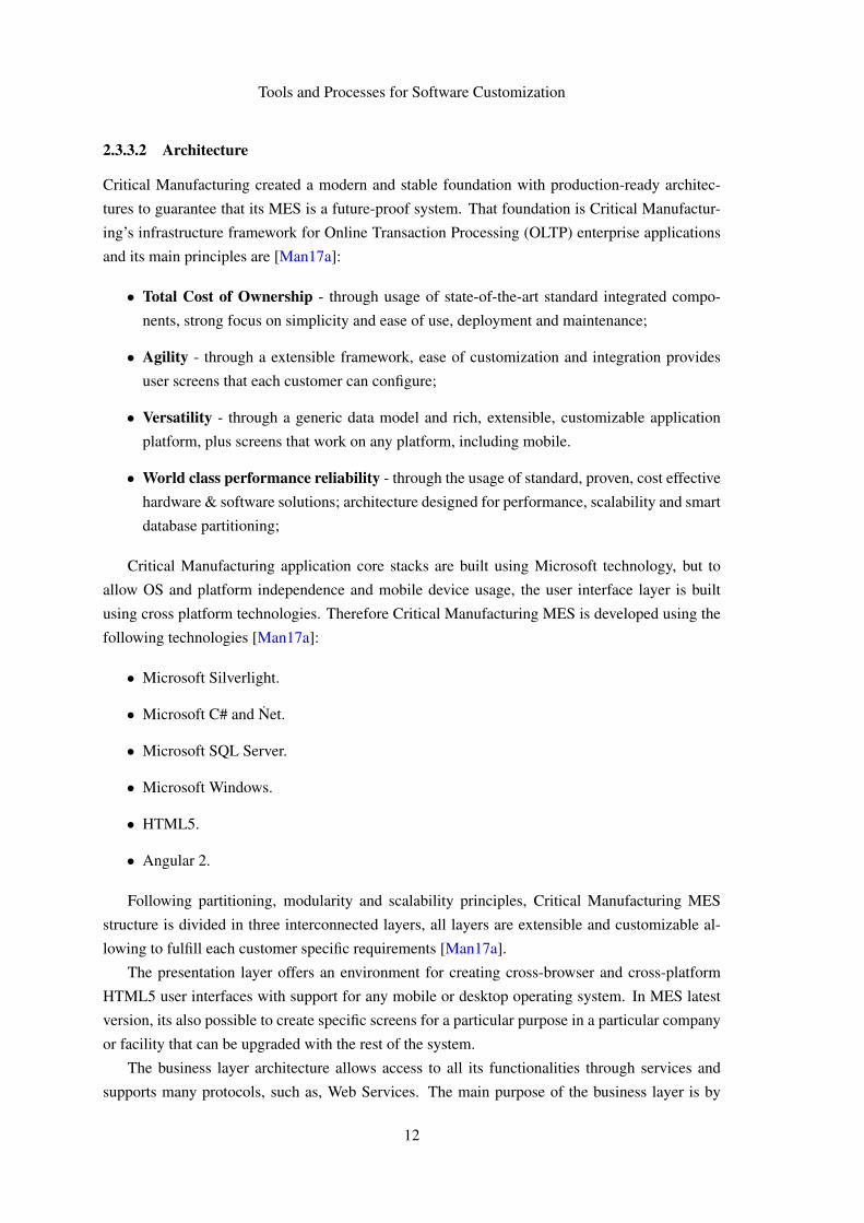
2.3.3.2 Architecture
Critical Manufacturing created a modern and stable foundation with production-ready architec-
tures to guarantee that its MES is a future-proof system. That foundation is Critical Manufactur-
ing’s infrastructure framework for Online Transaction Processing (OLTP) enterprise applications
and its main principles are [Man17a]:
• Total Cost of Ownership - through usage of state-of-the-art standard integrated compo-
nents, strong focus on simplicity and ease of use, deployment and maintenance;
• Agility - through a extensible framework, ease of customization and integration provides
user screens that each customer can configure;
• Versatility - through a generic data model and rich, extensible, customizable application
platform, plus screens that work on any platform, including mobile.
• World class performance reliability - through the usage of standard, proven, cost effective
hardware & software solutions; architecture designed for performance, scalability and smart
database partitioning;
Critical Manufacturing application core stacks are built using Microsoft technology, but to
allow OS and platform independence and mobile device usage, the user interface layer is built
using cross platform technologies. Therefore Critical Manufacturing MES is developed using the
following technologies [Man17a]:
• Microsoft Silverlight.
• Microsoft C# and Net.
• Microsoft SQL Server.
• Microsoft Windows.
• HTML5.
• Angular 2.
Following partitioning, modularity and scalability principles, Critical Manufacturing MES
structure is divided in three interconnected layers, all layers are extensible and customizable al-
lowing to fulfill each customer specific requirements [Man17a].
The presentation layer offers an environment for creating cross-browser and cross-platform
HTML5 user interfaces with support for any mobile or desktop operating system. In MES latest
version, its also possible to create specific screens for a particular purpose in a particular company
or facility that can be upgraded with the rest of the system.
The business layer architecture allows access to all its functionalities through services and
supports many protocols, such as, Web Services. The main purpose of the business layer is by
12

Tools and Processes for Software Customization
Figure 2.2: Critical Manufacturing MES Tiers [Man17a]
the means of the management of business objects, supply transparent functionalities to the upper
layers. The development of business objects followed OOP principles, which simplifies code reuse
between objects.
The data layer offers automatic data warehousing, reporting and data-mining features. At the
earliest opportunity, this layer is able to transfer data to the Operational Data Store (ODS) and to
the Data Warehouse (DWH) because of its runtime system optimization for reporting and business
intelligence.
2.3.3.3 Dynamic Execution Engine Actions
The Critical Manufacturing Customization Guide [Man17c] states that the Dynamic Execution
Engine (DEE or DE2) actions are the most powerful customization and extensibility mechanism
of the CMF MES. A DEE Action is a block of code written in C# language that is compiled and
executed in runtime and this execution can be requested either automatically or manually.
DEE actions are executed automatically by the system within the context of a service or oper-
ation as pre or post action.
It is also possible to execute the DEE Actions manually, explicitly requesting their execution
in the orchestration code or in the code of another DEE Action.
2.4 .NET Compiler Platform
Compilers are known to be mystical entities that process code through an obscure methodology
driven by a deep knowledge of the language, held only by the compiler creators.
For many years, according to [Uhl16, Boc16, Saa17], this was a perfectly acceptable arrange-
ment but that is no longer the case. Nowadays, the quality of our code and our productivity as
13

Tools and Processes for Software Customization
Figure 2.3: Pre or Post DEE Actions Mechanism [Man17c]
programmers depends on code analysis tools, and as these tools become more robust, their need
for knowledge comes close to the knowledge held only by the compiler.
The main purpose of the .NET Compiler Platform is to facilitate access to the knowledge and
information held by the compiler, providing an API that allows users and tools a broad under-
standing of the code. Converting from compiler to platform simplifies the creation of innovative
tools and applications in areas such as meta-programming, code generation and transformation.
2.4.1 Compiler Pipeline
The articles from [Uhl16, Boc16, Saa17] note that the .NET Compiler Platform ("Roslyn") pro-
vides the user with compiler’s code analysis through API that mimics the compiler pipeline struc-
ture.
Figure 2.4: .NET Compiler Pipeline and API [Uhl16]
The elements that make up the compiler pipeline are separated into four phases:
• Parse Phase - Source code tokens extraction and parsed into a syntax tree.
• Declaration Phase - Imported metadata and source code declarations analysis produces a
set of named symbols.
• Bind Phase - Connects source code identifiers with symbols.
• Emit Phase - Compiler builds and emits an assembly.
14

Tools and Processes for Software Customization
In each of the mentioned phases, the information produced by the compiler can be accessed
through an object, each phase exposes a different type of object: the parse phase object is a syntax
tree, a hierarchical symbol table is exposed by the declaration phase, the binding phase as a model
that exposes the result of the compiler’s semantic analysis and IL byte codes are produced by an
emit phase API.
Figure 2.5: .NET Compiler Platform APIs [Uhl16]
2.4.2 Compiler API
According to [Uhl16, Boc16, Saa17], the compiler APIs provides the objects associated with each
phase of the compilation process, allowing access to syntactic and semantic information. This
layer also stores an immutable snapshot of a single invocation of a compiler, that contains source
code files, assembly references and compiler options. The compiler offers two separate but similar
APIs for the C# language and the Visual Basic language.
The compiler analysis can produce a set of diagnostics such as syntactic errors, semantic
errors, assignment errors, warnings and informative diagnostics, etc. The API enables access to
compiler-generated diagnostics through an extension allowing third-party analyzers to track the
compilation process and generate their own diagnostics, such as showing "live squiggles" in the
editor and offering code fixes suggestions.
2.4.3 Workspaces API
The Workspaces API is mentioned by [Uhl16, Boc16, Saa17], as the cornerstone of solution code
analysis and refactoring. This API has several functionalities such as allowing direct access to
the informative objects exposed by the compiler without needing to parse files, group all the in-
formation about the projects of the solution in a single object, manage project references and
dependencies or compilation configurations.
15

Tools and Processes for Software Customization
Figure 2.6: .NET Compiler Platform Host Environment [Vas16]
2.4.4 Syntax Tree
In [Uhl16, Boc16, Saa17] is stated that the syntax tree is "the most fundamental data structure ex-
posed by the Compiler APIs" because it provides a lexical and syntactic source code representation
and fulfills two significant goals:
• Allows tools to gain access to the syntactic source code structure for representation and
analysis purposes.
• Enables tools to create, manipulate and transform the syntax tree in a easy manner.
Compilation, code generation, code analysis, refactoring and binding are just a few of the many
operations that use a syntax tree as its main structure in view of the fact that to fully understand
source code we must first bind its source code elements to the language entities.
The ability for storing all the unadulterated source code information is one of the main reasons
why the syntax tree is such an important compilation structure, it contains everything: grammatical
construct, lexical token, whitespace, comments and preprocessor directives.
Another reason is related to the fact that syntactic errors are also stored in the syntax tree and
are depicted as omitted or lacking tokens, this guarantees that from the syntax tree it is possible
to recreate the text that originated the tree in the first place and vice versa. This syntax tree
characteristic enables the ability to generate and edit text through syntax tree manipulation. In
other words, creating a tree is creating a analogous text and changing a tree is editing a existing
text to match the new edited tree.
16
Tools and Processes for Software Customization
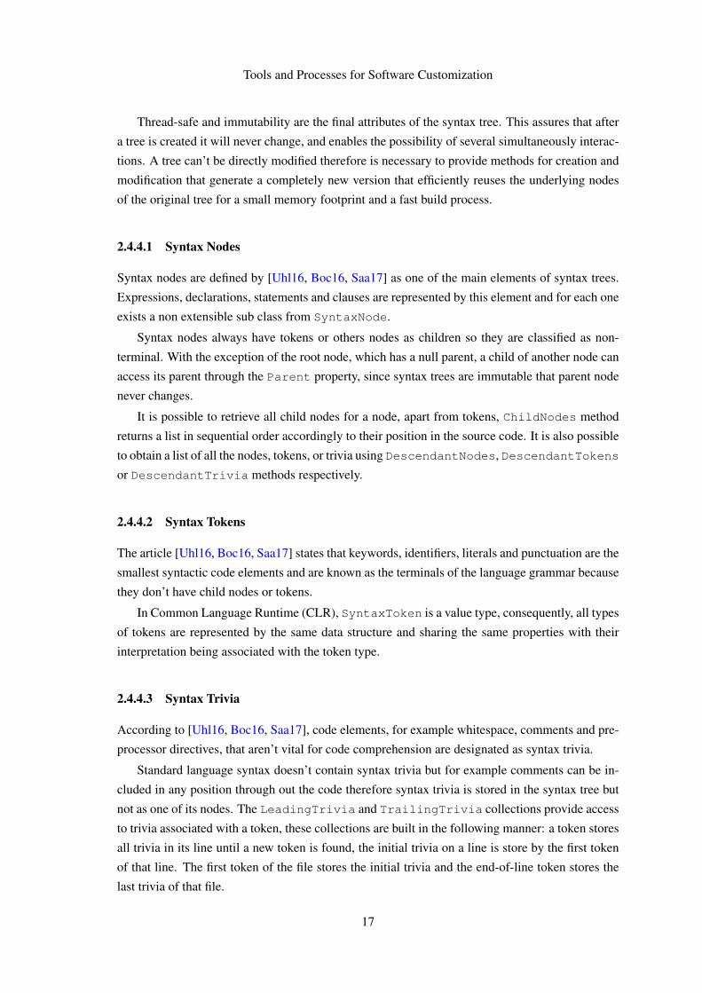
Thread-safe and immutability are the final attributes of the syntax tree. This assures that after
a tree is created it will never change, and enables the possibility of several simultaneously interac-
tions. A tree can’t be directly modified therefore is necessary to provide methods for creation and
modification that generate a completely new version that efficiently reuses the underlying nodes
of the original tree for a small memory footprint and a fast build process.
2.4.4.1 Syntax Nodes
Syntax nodes are defined by [Uhl16, Boc16, Saa17] as one of the main elements of syntax trees.
Expressions, declarations, statements and clauses are represented by this element and for each one
exists a non extensible sub class from SyntaxNode.
Syntax nodes always have tokens or others nodes as children so they are classified as non-
terminal. With the exception of the root node, which has a null parent, a child of another node can
access its parent through the Parent property, since syntax trees are immutable that parent node
never changes.
It is possible to retrieve all child nodes for a node, apart from tokens, ChildNodes method
returns a list in sequential order accordingly to their position in the source code. It is also possible
to obtain a list of all the nodes, tokens, or trivia using DescendantNodes, DescendantTokens
or DescendantTrivia methods respectively.
2.4.4.2 Syntax Tokens
The article [Uhl16, Boc16, Saa17] states that keywords, identifiers, literals and punctuation are the
smallest syntactic code elements and are known as the terminals of the language grammar because
they don’t have child nodes or tokens.
In Common Language Runtime (CLR), SyntaxToken is a value type, consequently, all types
of tokens are represented by the same data structure and sharing the same properties with their
interpretation being associated with the token type.
2.4.4.3 Syntax Trivia
According to [Uhl16, Boc16, Saa17], code elements, for example whitespace, comments and pre-
processor directives, that aren’t vital for code comprehension are designated as syntax trivia.
Standard language syntax doesn’t contain syntax trivia but for example comments can be in-
cluded in any position through out the code therefore syntax trivia is stored in the syntax tree but
not as one of its nodes. The LeadingTrivia and TrailingTrivia collections provide access
to trivia associated with a token, these collections are built in the following manner: a token stores
all trivia in its line until a new token is found, the initial trivia on a line is store by the first token
of that line. The first token of the file stores the initial trivia and the end-of-line token stores the
last trivia of that file.
17

Tools and Processes for Software Customization
Syntax trivia, such as syntax tokens, is a value type and the same structure is used by all the
different trivia types but in contrast with syntax tokens and nodes it doesn’t have parents although
it is possible to access the token that stores the trivia through the Token property.
2.4.4.4 Spans
[Uhl16, Boc16, Saa17] mentions that, in terms of position and length, each node, token or trivia
is aware of its number of characters and its position in the source code. A code element span is
denoted by a TextSpan object, that stores two integers, the span starting position and the span
length.
However a syntax tree node has two TextSpan properties, the Span property and the FullSpan
property, the former doesn’t include any leading and trailing trivia.
2.4.4.5 Kinds
RawKind is a property common to node, token or trivia that determines which code element is
represented by the object. C# and VB languages have a SyntaxKind enumeration that stores
all specific syntax elements in the language grammar and its possible to transform the RawKind
property in a specific kind using CSharpSyntaxKind() or VisualBasicSyntaxKind()
extension methods. This object property is essential, when it is not possible to differentiate two
syntax elements because they share the same node class, like in syntax tokens and trivia [Uhl16].
2.4.4.6 Errors
According to [Uhl16, Boc16, Saa17], a syntax tree with syntax errors is still represented by the
parser and is still possible to recreate the source code used in its generation. After a syntax error
is identified, the parser can still build a syntax tree using one of two fall back techniques:
• Missing Token - A specific kind of token is missing, the parser adds the missing token with
a null span length and sets the IsMissing property to true.
• Skipped Token - The parser ignores tokens until it is possible to restart the parsing process,
a trivia node of type SkippedTokens is created to store the ignored tokens.
2.4.5 Semantic Model
In the context of source code, as stated by [Uhl16, Boc16, Saa17], a semantic model relates to
semantic information as a syntax tree relates to lexical and syntactic information. Therefore, a
semantic model allows to inspect all semantic diagnostics that produce errors and warnings, the
type of a specific expression, the variables stream and referenced symbols in a specific part of
code. This wouldn’t be possible using only a syntax tree because without knowing the language
semantic rules it is not possible to precisely assert which code entity is referenced by a identifier.
For that reason, a semantic model contains the language semantic rules and the syntactic model,
allowing programs to refer also elements inside previously compiled libraries.
18
Tools and Processes for Software Customization
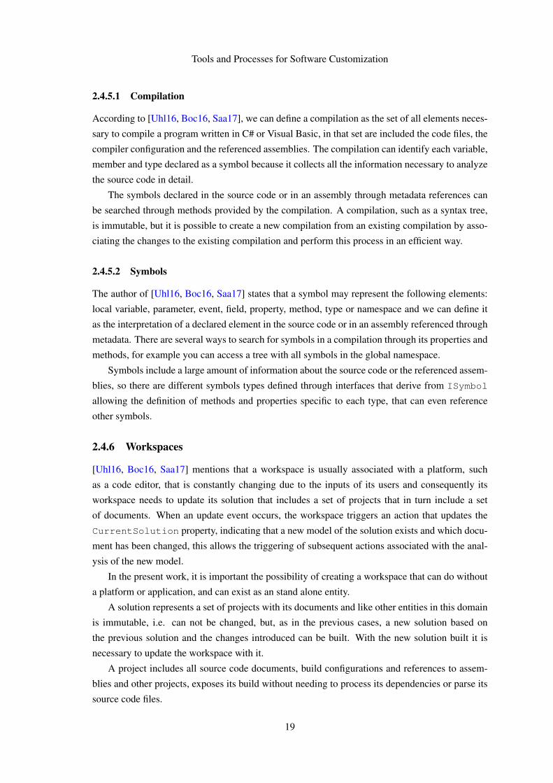
2.4.5.1 Compilation
According to [Uhl16, Boc16, Saa17], we can define a compilation as the set of all elements neces-
sary to compile a program written in C# or Visual Basic, in that set are included the code files, the
compiler configuration and the referenced assemblies. The compilation can identify each variable,
member and type declared as a symbol because it collects all the information necessary to analyze
the source code in detail.
The symbols declared in the source code or in an assembly through metadata references can
be searched through methods provided by the compilation. A compilation, such as a syntax tree,
is immutable, but it is possible to create a new compilation from an existing compilation by asso-
ciating the changes to the existing compilation and perform this process in an efficient way.
2.4.5.2 Symbols
The author of [Uhl16, Boc16, Saa17] states that a symbol may represent the following elements:
local variable, parameter, event, field, property, method, type or namespace and we can define it
as the interpretation of a declared element in the source code or in an assembly referenced through
metadata. There are several ways to search for symbols in a compilation through its properties and
methods, for example you can access a tree with all symbols in the global namespace.
Symbols include a large amount of information about the source code or the referenced assem-
blies, so there are different symbols types defined through interfaces that derive from ISymbol
allowing the definition of methods and properties specific to each type, that can even reference
other symbols.
2.4.6 Workspaces
[Uhl16, Boc16, Saa17] mentions that a workspace is usually associated with a platform, such
as a code editor, that is constantly changing due to the inputs of its users and consequently its
workspace needs to update its solution that includes a set of projects that in turn include a set
of documents. When an update event occurs, the workspace triggers an action that updates the
CurrentSolution property, indicating that a new model of the solution exists and which docu-
ment has been changed, this allows the triggering of subsequent actions associated with the anal-
ysis of the new model.
In the present work, it is important the possibility of creating a workspace that can do without
a platform or application, and can exist as an stand alone entity.
A solution represents a set of projects with its documents and like other entities in this domain
is immutable, i.e. can not be changed, but, as in the previous cases, a new solution based on
the previous solution and the changes introduced can be built. With the new solution built it is
necessary to update the workspace with it.
A project includes all source code documents, build configurations and references to assem-
blies and other projects, exposes its build without needing to process its dependencies or parse its
source code files.
19

Tools and Processes for Software Customization
A document is a source code file that exposes its text, syntax tree and semantic model.
2.5 Collective Knowledge Systems
According to [Gru07], we live in a time where the knowledge-sharing network is extremely effi-
cient and covers a wide range of people who are experts in their fields. This system offers a large
amount of information and a wide range of perspectives, publicly available and without access
restrictions. Therefore, collective knowledge is the ultimate goal. However, today, that sharing
network only offers a collected knowledge: user contributions are collected and aggregated in a
specific domain.
The author of [Gru07], states that we should aim to a collective knowledge and that the Inter-
net is our best knowledge sharing network. The path to this goal is an interaction between humans
and computers. Humans are the producers and consumers of the system, providing their knowl-
edge and their problems. Computers are the medium, to store and allow the search of knowledge
and simultaneously seek to generate latent knowledge. With the medium created by computers,
humans can communicate and generate new knowledge in a more efficient way. Computers are
now able to extract knowledge from human-provided information with very satisfactory results,
but these processes are limited by the collection of information because the tasks of converting raw
information into information that can be processed by a computer are extremely time consuming.
But today we can turn to the Social Web, where millions of humans share their knowledge on
platforms that store, share and allow the search of this information and with it, we can build a
collective knowledge.
Figure 2.7: Example of a Collective Knowledge System [Gru07]
A Collective Knowledge system (CKS) is a human computer interaction based on the ability
20

Tools and Processes for Software Customization
of computers to process, structure and do data reasoning from large volumes of human knowl-
edge. The shared properties between a Collective Knowledge System and a Collected Knowledge
System are:
• User-Generated Content - The participation of humans in the Social Web produce a lot of
data that is structured and stored by the platform.
• Human-Machine Synergy - The interaction between humans and computers allows us to
produce a volume of useful information that could not be obtained otherwise. The volume,
coverage and diversity of perspectives provided by this information is unparalleled by the
bibliography or the opinion of experts.
• Increasing Returns with Scale - The system encourages users to contribute information
through rewards and the utility of the system increases due to contributions increase.
The transformation of Collected Knowledge System into a Collective Knowledge System re-
quires an additional property:
• Emergent Knowledge - The data collected by the system is processed and analyzed in
order to extrapolate and discover new knowledge that were not stated in the community
contributions.
Emergent Knowledge in Collective Knowledge Systems is inspired by the possibilities cre-
ated by technology to improve the creation and discovery of knowledge using widely available
collections of human knowledge and the extraction of latent data connections.
2.6 Topic Modeling
In machine learning and natural language processing, according to [GH11], topic models are sta-
tistical entities that offer a probabilistic modeling for the term frequency occurrences in a set of
documents, designated corpus. The order of words in a document is considered irrelevant due to
the fact that topic models process only term frequencies occurrences, mirroring "bag-of-words"
models.
The author of [Uhl16] states that topic modeling is an effective technique for identifying re-
lationships in large volumes of text. The most common type of topic modeling is called Latent
Dirichlet Allocation (LDA), where mining text is done through a statistical machine learning pro-
cess that creates clusters of words named topics and clusters of documents into a mix of topics.
The cornerstone of LDA is a Bayesian inference model where documents have a probability
distribution over topics while topics are related to words also through a probability distribution.
A probability distribution describes a random phenomenon through the probability of events
of that phenomenon, in other words, it is a mathematical function that relates a particular event in
an experience with the probability of that event occurring.
21

Tools and Processes for Software Customization
A Bayesian inference is a statistical inference process that uses Bayes’ theorem to update
the probability of a given event whenever new data is known. This type of inference allows the
use of new data to improve the current model, through an iterative process that updates a certain
probability according to the new data in order to improve the resulting new probability.
In the context of topic modeling, our data are documents so its main objective is to group the
words of the documents in topics and identify the topics covered in each document through the
analysis of those same documents and with the possibility of improving our model of topics due
to the analysis of new documents.
2.6.1 Machine Learning
Machine learning is a domain that encompasses artificial learning techniques with the characteris-
tic of being able to update a model based on new data. The evaluation of the results produced by
the modifications to the model allows guiding future modifications in order to increase the quality
of the results produced. Typically, machine learning algorithms can be divided into the following
main tasks [Dic17]:
• Execution.
• Evaluation of the output results.
• Tuning the input parameters to increase the quality of the output results.
• Initialize a new algorithm iteration.
The Machine Learning domain can be divided into two broad areas, supervised and unsuper-
vised learning. In supervised learning, the algorithm model is trained and this implies that the
data set used is previously classified. In the case of unsupervised learning, the performance of the
algorithm model is evaluated through parameters extracted from the environment that hosts the
model.
The area of non-supervised learning includes a sub-area called unsupervised statistical learning
where we can include the Topic Modeling algorithm. The inclusion in this sub-area is justified by
the use of a Bayesian inference model as the host environment evaluation parameter for performing
the model tuning in an unsupervised way. Unlike document clustering, where each document
belongs to only one topic, in topic modeling a document can belong to multiple topics.
2.6.2 Data Mining
The article [Dic17] mentions that the primary goal of Data Mining is to examine and extract
latent relationships in a vast, unstructured dataset. Therefore, Data Mining techniques involve
a preprocessing of the input data in order to guarantee an efficient and correct interpretation of
the data by the algorithm, however the techniques of Data Mining are usually very complex and
time-consuming. The data preparation stage can be divided into two tasks: discarding incorrect,
22

Tools and Processes for Software Customization
incomplete or divergent data and then reducing, each of the data set elements, to the characteristics
considered important for the scope under study.
In topic modeling, the data set is composed of text files so the data preparation step consists of
reducing the text files only to its words. Then, stop words are removed. Stop words are the most
common words in the language in which the text files are written and which, due to their frequent
use, affect the quality of the topic model through the generation of irrelevant topics. The thematic
context of the text files may demand the creation of an additional custom stop words list.
Data clusters are the foundation of topic modeling. It is a multi phase clustering technique that
builds clusters of words called topics and clusters of documents into a set of topics.
2.6.3 Topic Model Specification and Estimation
In topic models generated with LDA, it is necessary to set the number of topics k because it is one
of the input parameters of the algorithm. The topic model is built considering a document w =
(w1, ...,wn) of a corpus D with N words that belong to a vocabulary of V terms, where wi ∈ 1, ...,V
for all i = 1, ...N. The process can be divided in three stages [GH11]: (1) the term distribution β
is determined for each topic by β ∼ Dirichlet(δ ), (2) the proportions θ of the topic distribution
for the document w are determined by θ ∼ Dirichlet(α), (3) for each of the N words wi: choose
a topic zi ∼ Multinomial(δ ) and choose a word wi from a multinomial probability distribution
conditioned on the topic zi : p(wi|zi,β ). β is the term distribution of topics and contains the
probability of a word occurring in given topic.
In the article [GH11] is stated that the input data, before being supplied to the topic model
algorithm, has to be converted into a document-term matrix. The matrix rows represent the corpus
documents and the columns represent the terms of the vocabulary. Therefore, a matrix cell stores
information about the column’s term frequency occurrences in the row’s document.
One of the tasks of the data processing stage is vocabulary definition: to select the most mean-
ingful words in the available data. The words in each document of the corpus are counted for the
creation of a bag-of-words, for this it is necessary to carry out a cleaning of each document re-
moving punctuation, numbers, stop words and words with dimension smaller than a certain value.
The document’s bag-of-words enables the creation of the document-term matrix, but this matrix
can be further improved by using words that occur in, at least, a minimum number of documents
or by selecting the words that will constitute the final matrix with highest term-frequency inverse
document frequency (TF-IDF) indicator. The matrix always stores the frequency of the terms, the
TF-IDF indicator only serves to select the terms contained in the final matrix.
2.7 Chapter Summary
Software customization is the main topic of this dissertation and this chapter addresses its def-
inition, the support provided by software frameworks for customization and the importance of
tools and documentation for an effective use of these development environments. Therefore, the
23

Tools and Processes for Software Customization
inherent software customization difficulties and the review of the technologies used in this disser-
tation lay the groundwork for the description of the problem and the understanding of the proposed
solution in the next chapter.
24
Chapter 3
Improving Software CustomizationTools and Processes
In the context of Manufacturing Execution Systems, the main goal of this work is assess which
solutions in the software framework domain can more strongly improve the software customization
process.
This chapter defines the scope and characteristics of the problem and outlines the proposed
solutions, while giving reasons for its selection. Finally, is mentioned the expected results for the
problem at hands.
3.1 Problem Description
This work is developed in a enterprise environment, specifically in the company Critical Manu-
facturing and its main product is a Manufacturing Execution System. Manufacturing Execution
System (MES) is a system that manages and oversees all steps of a manufacturing process in a fac-
tory floor and displays real-time information from the production operations so the management
team can make decision supported by up-to-date information.
A MES system must display a high level of performance taking into consideration the large
volumes of information it has to process, yet it should also be a competitive product and ad-
dress customers needs and goals. As each customer have specific needs and goals, since different
customers have different products therefore need different features, a MES system must offer cus-
tomization and extensibility capabilities in order to stay relevant in its market.
Software customization is a product of a hybrid business model approach to the software
market, triggered by the advantages of a merge between a product business model and a service
business model. The product business model supplies a generic software product with generic
maintenance and support service while the service business model offers customization frame-
works to enable modifications and additional features so that specific customers needs are meet.
25
Improving Software Customization Tools and Processes
But harmonize generic maintenance and support services with specific customers features is a
challenging task.
Software frameworks are the ideally platform to overcome this challenging task, one of the
main purposes of software frameworks is to simplify and speed up development of specific cus-
tomer features by enabling developers to override, modify or extend by user-written code a generic
functionality. To take full advantage of a software framework, users need to understand its design
principles and architecture to learn how to use it and to simplify and minimize this learning effort,
good framework tools and documentation are essential.
Framework tools and documentation are a substantial factor in framework adoption but aren’t
immune to problems. If badly designed or highly complex, framework tools will only be accessible
to highly skilled users or will require long training periods. Framework documentation is an
expensive and time consuming task that may lead to incomplete or outdated documentation, and
all of this will amount to low framework adoption rates.
Software frameworks are a vast and highly complex domain, where there are many valid solu-
tions for framework tools and documentation problems. Nevertheless our work scope is a subset
of this domain, software framework for customizing a MES system, therefore we must first char-
acterize and understand the specific problems that occur on this subset before we can select and
implement the more suitable solutions from the software frameworks domains, thus designing and
tailoring a MES customization support strategy.
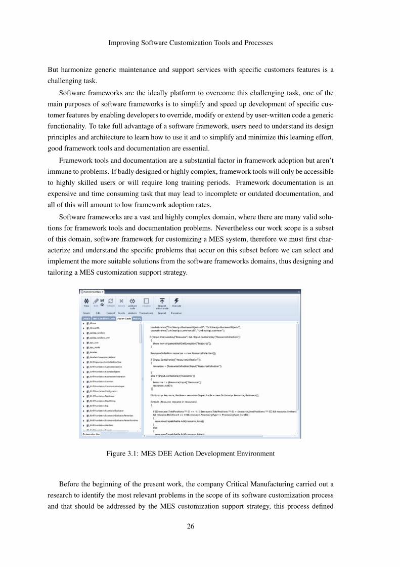
Figure 3.1: MES DEE Action Development Environment
Before the beginning of the present work, the company Critical Manufacturing carried out a
research to identify the most relevant problems in the scope of its software customization process
and that should be addressed by the MES customization support strategy, this process defined
26
Improving Software Customization Tools and Processes
the most relevant improvement for each of the areas (tools and documentation) of software cus-
tomization. It has concluded that the tool that supports the development of MES DEE actions by
customers and partners needs to be improved in order to provide a more reliable and faster devel-
opment environment with the ability to display real-time code information and recommendations.
And at the documentation level, should be investigated a way to produce documentation that helps
users of the MES customization platform in designing their DEE actions, while consuming less
resources from the platform development team in creating and maintaining that documentation.
The results of the analysis of the MES customization process are the starting point of the present
work, characterize the addressed problems and its solutions define the expected work results.
3.2 Solution
The solution proposed in this work covers the two areas of software customization support, tools
and documentation. And is oriented to solve the most pertinent problems identified by the com-
pany Critical Manufacturing in its customization process. The improvement of the MES cus-
tomization process will be supported by:
• The construction of a code editor for the development of the system DEE actions.
• A method of documentation generation using a text mining technique applied to existing
DEE action sets.
The code editor eases the development process and increases confidence in the DEE action
developed by offering the following code analysis features:
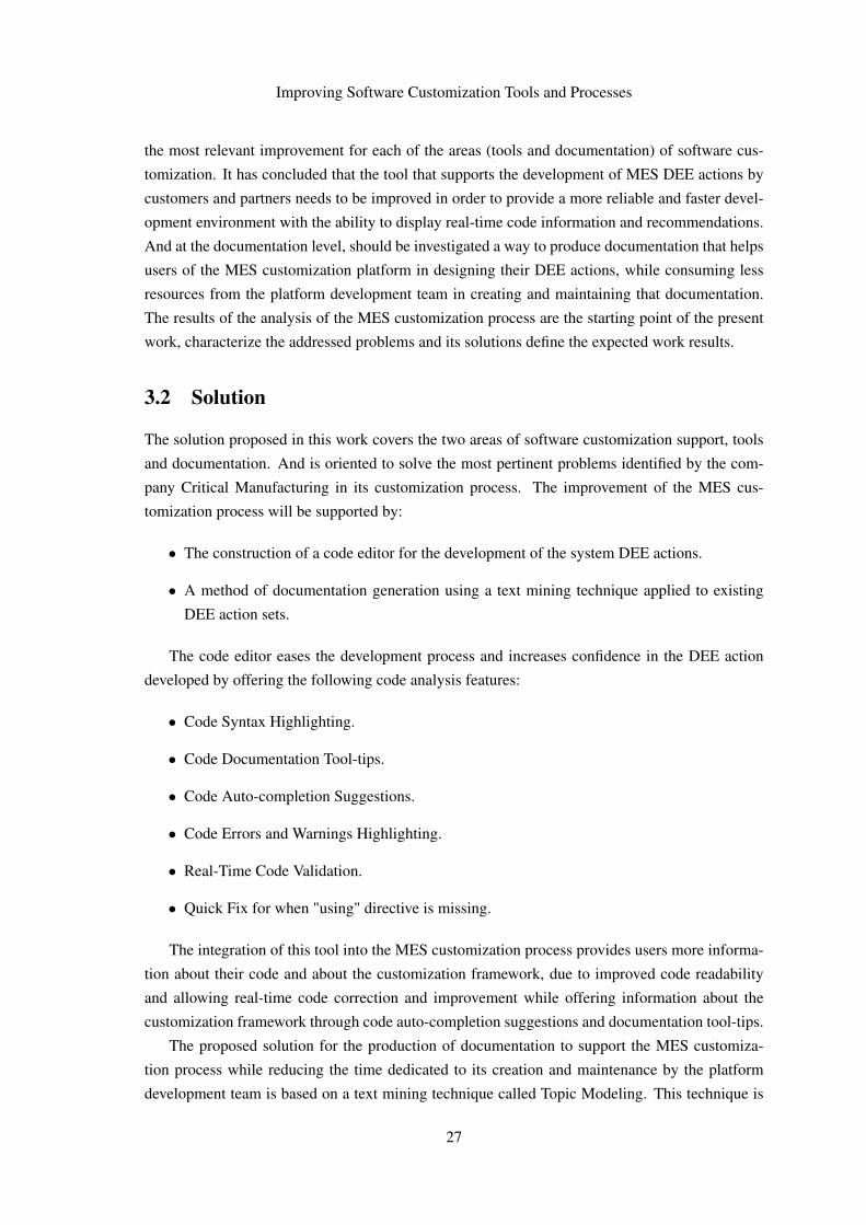
• Code Syntax Highlighting.
• Code Documentation Tool-tips.
• Code Auto-completion Suggestions.
• Code Errors and Warnings Highlighting.
• Real-Time Code Validation.
• Quick Fix for when "using" directive is missing.
The integration of this tool into the MES customization process provides users more informa-
tion about their code and about the customization framework, due to improved code readability
and allowing real-time code correction and improvement while offering information about the
customization framework through code auto-completion suggestions and documentation tool-tips.
The proposed solution for the production of documentation to support the MES customiza-
tion process while reducing the time dedicated to its creation and maintenance by the platform
development team is based on a text mining technique called Topic Modeling. This technique is
27

Improving Software Customization Tools and Processes
usually applied to texts in natural language, but in this work the data used will be the code of the
existing MES DEE actions. The final objective will be to create a table of contents of the MES
DEE actions, this index of topics allows the search and discovery of DEE actions that fit within a
certain scope represented by the topic.
The MES DEE actions have an inherent knowledge that was not, until now, easily accessible
to users of the platform, but through this index of topics it is possible to structure the information
and convert it into a learning and support instrument for new and current users.
In a work not limited by the temporal constraints of a dissertation, the MES DEE actions topic
model would be one of the modules of a Collective Knowledge System but a fully fledged CKS
requires a active community and that was unfeasible to gather within the duration of this work.
Thus it is possible to frame the DEE actions topic model in the context of Collective Knowledge
System as a way to emerge knowledge from user-generated content however this work isn’t able
to fully explore the CKS key properties, specially human-machine synergy and increasing returns
with scale.
3.3 Expected Results
The implementation of the proposed solution for the MES customization support tools and doc-
umentation seeks to produce results that make the product more attractive by adapting faster and
more easily to the specific challenges of each client or partner. In addition, allowing a broad
set of enabled users to develop customization actions will lead to an increased flexibility in the
management of the customer human resources.
The features introduced with the new code editor seek to reduce the learning curve associated
with the development of DEE actions, extending the group of developers enabled to its develop-
ment and reducing the time of training of new users of the platform.
The new code editor provides a more readable and informative development environment,
more information about errors and warnings allows new users to learn from their errors, and cur-
rent users have greater confidence in the code they develop. While providing a more efficient and
quick correction of the code and a respective reduction in development time.
The auto-completion suggestions provided by the code editor, with each suggestion offering its
respective documentation information, are an important learning and support tool for users of all
levels. Because they allow to consult information about the various entities (Classes, Methods, ...)
in the framework without having to leave the editor, contributing once again to a greater confidence
in the written code and a faster development.
The DEE action topic model is expected to produced a new kind of support documentation
while requiring a low amount of input by the framework development team. The topic model
is expected to offer a way to search and discover previously implemented DEE actions that fall
within a certain scope therefore providing knowledge to develop new DEE actions that are within
the same scope.
28

Improving Software Customization Tools and Processes
In a scientific perspective, it is expected that at the end of the work it will be possible to
conclude if the application of topic models to this domain of code documentation is a path that
should be explored in greater detail.
All improvements resulting from the proposed solution will have the effect of making the MES
customization process more attractive to customers and partners and consequently increasing the
DEE actions framework usage rate.
In summary, the solutions proposed and implemented in this work were designed with the
following results in mind:
• Faster and reliable customization process.
• Increase the confidence and efficiency of the development.
• Shorter framework training periods.
• Higher framework adoption rate.
3.4 Chapter Summary
The description of software customization problems and difficulties allows us to understand the
rationale behind the proposed solution. Thus, after understanding this choice of a solution consist-
ing of a code editor with code analysis features and a documentation generated using text mining,
the following chapter will report on its implementation process, the solution’s technologies and
the obtained results.
29

Improving Software Customization Tools and Processes
30

Chapter 4
Implementation and Results
This chapter will focus on the concepts, architecture and design decisions that support the imple-
mentation of this work and it will also cover the work results and the validation process.
The information contained in this chapter will allow the reader to understand how the data is
processed by the applications, how the various layers of the applications interact with each other,
how the communication between the applications work, how the applications are structured, how
the two systems are organized and other design decisions.
The last part of the chapter will describe how the validation process was performed as well as
analyze the validation process results.
The chapter’s structure is divided into two main sections: DEE Action Code Editor and DEE
Action Topic Model. Each one of those sections has the following three sub-sections: Implemen-
tation, Technologies and Results.
4.1 DEE Action Code Editor
As mentioned in the previous chapter, the code editor eases the development process and increases
confidence in the DEE action developed by offering code analysis features such as:
• Code Syntax Highlighting.
• Code Documentation Tool-tips.
• Code Auto-completion Suggestions.
• Code Errors and Warnings Highlighting.
• Real-Time Code Validation.
• Quick Fix for when a using directive is missing.
31
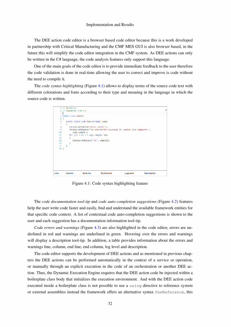
Implementation and Results
The DEE action code editor is a browser based code editor because this is a work developed
in partnership with Critical Manufacturing and the CMF MES GUI is also browser based, in the
future this will simplify the code editor integration in the CMF system. As DEE actions can only
be written in the C# language, the code analysis features only support this language.
One of the main goals of the code editor is to provide immediate feedback to the user therefore
the code validation is done in real-time allowing the user to correct and improve is code without
the need to compile it.
The code syntax highlighting (Figure 4.1) allows to display terms of the source code text with
different colorations and fonts according to their type and meaning in the language in which the
source code is written.
Figure 4.1: Code syntax highlighting feature
The code documentation tool-tip and code auto-completion suggestions (Figure 4.2) features
help the user write code faster and easily, find and understand the available framework entities for
that specific code context. A list of contextual code auto-completion suggestions is shown to the
user and each suggestion has a documentation information tool-tip.
Code errors and warnings (Figure 4.3) are also highlighted in the code editor, errors are un-
derlined in red and warnings are underlined in green. Hovering over the errors and warnings
will display a description tool-tip. In addition, a table provides information about the errors and
warnings line, column, end line, end column, log level and description.
The code editor supports the development of DEE actions and as mentioned in previous chap-
ters the DEE actions can be performed automatically in the context of a service or operation,
or manually through an explicit execution in the code of an orchestration or another DEE ac-
tion. Thus, the Dynamic Execution Engine requires that the DEE action code be injected within a
boilerplate class body that initializes the execution environment. And with the DEE action code
executed inside a boilerplate class is not possible to use a using directive to reference system
or external assemblies instead the framework offers an alternative syntax UseReference, this
32
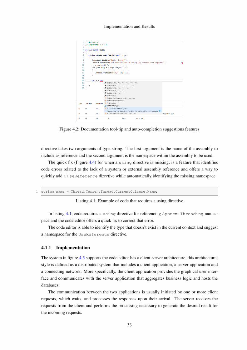
Implementation and Results
Figure 4.2: Documentation tool-tip and auto-completion suggestions features
directive takes two arguments of type string. The first argument is the name of the assembly to
include as reference and the second argument is the namespace within the assembly to be used.
The quick fix (Figure 4.4) for when a using directive is missing, is a feature that identifies
code errors related to the lack of a system or external assembly reference and offers a way to
quickly add a UseReference directive while automatically identifying the missing namespace.
1 string name = Thread.CurrentThread.CurrentCulture.Name;
Listing 4.1: Example of code that requires a using directive
In listing 4.1, code requires a using directive for referencing System.Threading names-
pace and the code editor offers a quick fix to correct that error.
The code editor is able to identify the type that doesn’t exist in the current context and suggest
a namespace for the UseReference directive.
4.1.1 Implementation
The system in figure 4.5 supports the code editor has a client-server architecture, this architectural
style is defined as a distributed system that includes a client application, a server application and
a connecting network. More specifically, the client application provides the graphical user inter-
face and communicates with the server application that aggregates business logic and hosts the
databases.
The communication between the two applications is usually initiated by one or more client
requests, which waits, and processes the responses upon their arrival. The server receives the
requests from the client and performs the processing necessary to generate the desired result for
the incoming requests.
33
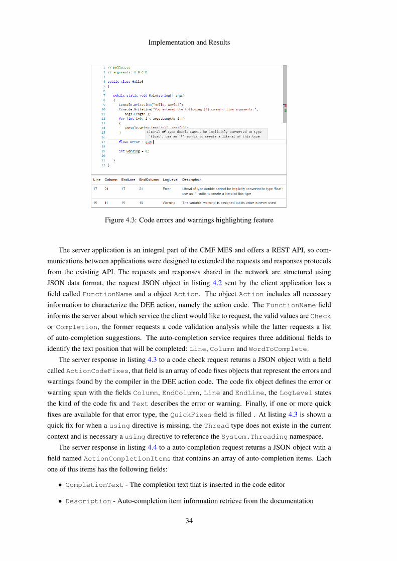
Implementation and Results
Figure 4.3: Code errors and warnings highlighting feature
The server application is an integral part of the CMF MES and offers a REST API, so com-
munications between applications were designed to extended the requests and responses protocols
from the existing API. The requests and responses shared in the network are structured using
JSON data format, the request JSON object in listing 4.2 sent by the client application has a
field called FunctionName and a object Action. The object Action includes all necessary
information to characterize the DEE action, namely the action code. The FunctionName field
informs the server about which service the client would like to request, the valid values are Check
or Completion, the former requests a code validation analysis while the latter requests a list
of auto-completion suggestions. The auto-completion service requires three additional fields to
identify the text position that will be completed: Line, Column and WordToComplete.
The server response in listing 4.3 to a code check request returns a JSON object with a field
called ActionCodeFixes, that field is an array of code fixes objects that represent the errors and
warnings found by the compiler in the DEE action code. The code fix object defines the error or
warning span with the fields Column, EndColumn, Line and EndLine, the LogLevel states
the kind of the code fix and Text describes the error or warning. Finally, if one or more quick
fixes are available for that error type, the QuickFixes field is filled . At listing 4.3 is shown a
quick fix for when a using directive is missing, the Thread type does not existe in the current
context and is necessary a using directive to reference the System.Threading namespace.
The server response in listing 4.4 to a auto-completion request returns a JSON object with a
field named ActionCompletionItems that contains an array of auto-completion items. Each
one of this items has the following fields:
• CompletionText - The completion text that is inserted in the code editor
• Description - Auto-completion item information retrieve from the documentation
34
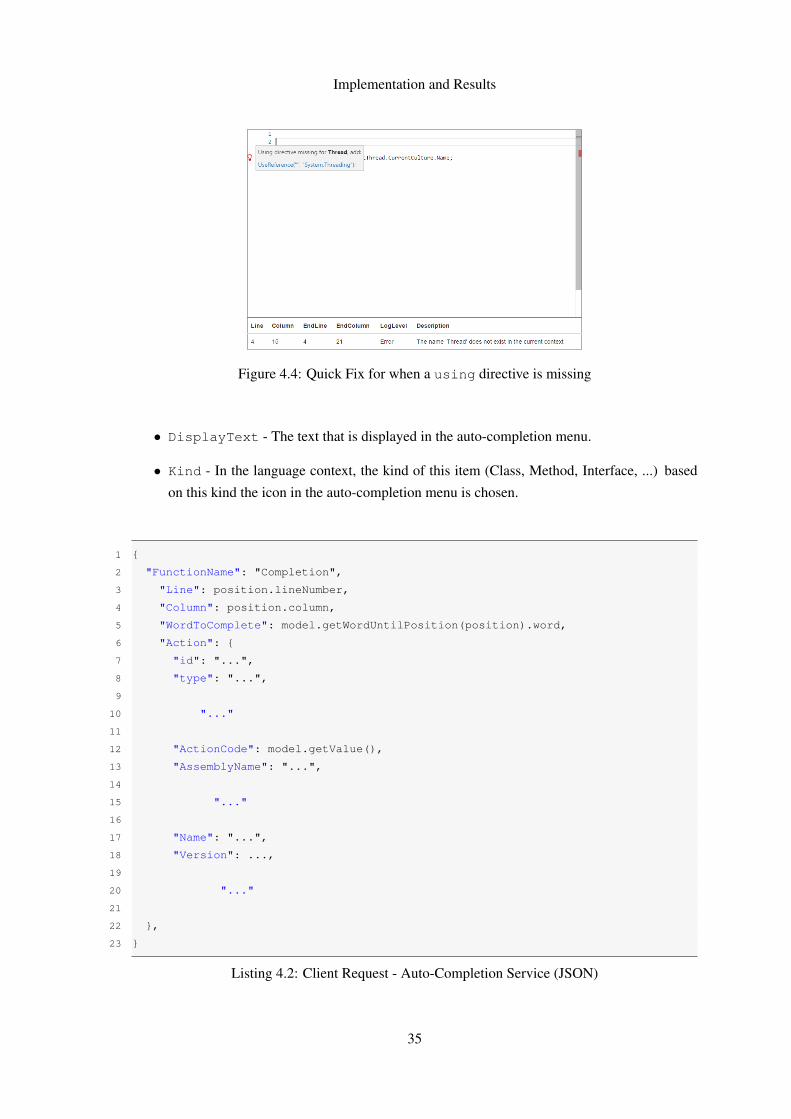
Implementation and Results
Figure 4.4: Quick Fix for when a using directive is missing
• DisplayText - The text that is displayed in the auto-completion menu.
• Kind - In the language context, the kind of this item (Class, Method, Interface, ...) based
on this kind the icon in the auto-completion menu is chosen.
1 {
2 "FunctionName": "Completion",
3 "Line": position.lineNumber,
4 "Column": position.column,
5 "WordToComplete": model.getWordUntilPosition(position).word,
6 "Action": {
7 "id": "...",
8 "type": "...",
9
10 "..."
11
12 "ActionCode": model.getValue(),
13 "AssemblyName": "...",
14
15 "..."
16
17 "Name": "...",
18 "Version": ...,
19
20 "..."
21
22 },
23 }
Listing 4.2: Client Request - Auto-Completion Service (JSON)
35

Implementation and Results
At listing 4.4, the auto-completion item represents a Site class that belongs to the CMF
libraries. The code editor allows the use of code snippets so $0 marks the position of the cursor
when the user selects this auto-completion item with a TAB key press.
Figure 4.5: System Client-Server Architecture
4.1.1.1 Client Application
The client application in figure 4.6, hosts the code editor GUI is a web server that runs in Node.js
run-time environment, the sole purpose of this Node.js server is produce a web page with a cus-
tomize Monaco Code Editor. Monaco Code Editor is the client-side code editor that powers Visual
Studio Code, it was chosen because is a very complete browser based code editor and is already
use in the CMF MES GUI.
1 {
2 "id": "1",
3 "type": "...",
4 "Action": {
5
6 "..."
7
8 },
9 "ActionCodeFixes": [
10 {
11 "id": "...",
12 "type": "...",
13 "Id": "CS0103",
14 "Column": 78,
15 "EndColumn": 84,
16 "Line": 126,
17 "EndLine": 126,
18 "LogLevel": "Error",
19 "Text": "The name "Thread" does not exist in the current context",
20 "Scope": "Action Code",
21 "QuickFixes": [
36

Implementation and Results
22 {
23 "id": "...","$type": "...",
24 "UsingType": "Thread",
25 "UsingNamespace": "System.Threading"
26 }
27 ]
28 },
29 ],
30 }
Listing 4.3: Server Response - Code Check Service (JSON)
The Monaco Editor is the core of our code editor GUI and it was loaded into our web server
as a npm module. The Monaco Editor API structure is divided in three main modules: editor,
languages and worker. The main purpose of our code editor is to support DEE action develop-
ment in C# language therefore it was necessary to connect to the languages module to provide
our code analysis features.
1 {
2 "id":"...",
3 "type":"...",
4 "Action":{
5
6 "..."
7
8 },
9 "ActionCompletionItems":[
10 {
11 "id": "...",
12 "type": "...",
13 "CompletionText":"Site$0",
14 "Description":"This code was generated by Cmf.\nSite implementation
class\nSite Object\n",
15 "DisplayText":"Site",
16 "Kind":"Class"
17 }
18 ]
19 }
Listing 4.4: Server Response - Auto-Completion Service (JSON)
The first step was to register the C# language in the languages API module, this enabled C# ba-
sic syntax colorization in our code editor and to connect additional features providers to the C# lan-
guage. The languages API offers several provider register methods (registerHoverProvider,
registerHoverProvider, registerCodeLensProvider, ...) but to implement our fea-
tures only one was use, the registerCompletionItemProvider. The code check provider
37

Implementation and Results
was custom made using other API calls from the editor module because languages API mod-
ule doesn’t offer a similar provider.
Figure 4.6: Client Layered Architecture
The real-time validation of the code check provider, displayed in figure 4.7, is possible through
a editor module event onDidChangeModelContent that is triggered when the content of the
editor is changed.
The code check provider sends a code check request that contains the source code in the editor,
when the server response arrives, the provider uses the API call setModelMarkers to highlight
the code error and warnings, adds quick fix options to the editor gutters with deltaDecorations
method and updates the code errors and warnings table.
Figure 4.7: Code Check Sequence Diagram
38
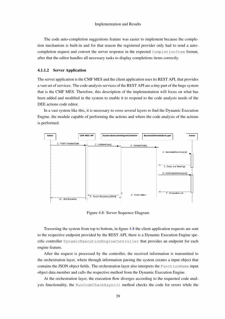
Implementation and Results
The code auto-completion suggestions feature was easier to implement because the comple-
tion mechanism is built-in and for that reason the registered provider only had to send a auto-
completion request and convert the server response in the expected CompletionItem format,
after that the editor handles all necessary tasks to display completions items correctly.
4.1.1.2 Server Application
The server application is the CMF MES and the client application uses its REST API, that provides
a vast set of services. The code analysis services of the REST API are a tiny part of the huge system
that is the CMF MES. Therefore, this description of the implementation will focus on what has
been added and modified in the system to enable it to respond to the code analysis needs of the
DEE actions code editor.
In a vast system like this, it is necessary to cross several layers to find the Dynamic Execution
Engine, the module capable of performing the actions and where the code analysis of the actions
is performed.
Figure 4.8: Server Sequence Diagram
Traversing the system from top to bottom, in figure 4.8 the client application requests are sent
to the respective endpoint provided by the REST API, there is a Dynamic Execution Engine spe-
cific controller DynamicExecutionEngineController that provides an endpoint for each
engine feature.
After the request is processed by the controller, the received information is transmitted to
the orchestration layer, where through information parsing the system creates a input object that
contains the JSON object fields. The orchestration layer also interprets the FunctionName input
object data member and calls the respective method from the Dynamic Execution Engine.
At the orchestration layer, the execution flow diverges according to the requested code anal-
ysis functionality, the RunCodeCheckAsync() method checks the code for errors while the
39

Implementation and Results
GetCompletionsAsync() method provides code completion suggestions, both this methods
belong to the Action class in the Dynamic Execution Engine layer.
The two methods create a CodeEditor class object that creates a virtual .Net Compliler
Platform Workspace and store the code editor present state:
• Adhoc Workspace creation and set up.
• Workspace project creation.
• Add references to the workspace project.
• Project document creation.
• Add source code text to the project document.
The CodeEditor object is essential in the creation and preparation of the conditions for the
use of .Net Compiler Platform API, without this previous set up it is not possible to create a syntax
tree or a semantic model.
As previously mentioned, the .Net Compiler Platform Workspace is the root node of a C#
hierarchy and our project uses a Adhoc workspace because it allows to add a solution and project
files manually, this workspace is a quick and easy way to create a workspace and add projects
and documents to it. Given that our project needs to easily manipulate the workspace and its
components, this workspace type is the right option.
The CodeEditor object also adds to the project the necessary system and external assembly
references to a enable a successful source code compilation.
The RunCodeCheckAsync() method uses the compiler API to obtain the source code se-
mantic model and from that model is possible to run a diagnosis analysis that identifies the code
errors and warnings. If a using directive error is detected an additional process is run where the
global namespace tree is transversed in search of a type that match the source code word associ-
ated with error, when the search is successful the type namespace is used for providing a quick
fix.
Using the request information, the GetCompletionAsync() method first step is locate the
source code word position for completion contextual purposes, then transfers that information to
a .Net Compiler Platform API service that returns a completion items list. The list elements are
analyzed using the word to complete sent by the service request and a final completions list is
created.
4.1.2 Technologies
The technologies used in the DEE action code editor are different between the client and server
application, having as only common ground the REST API through which they communicate.
40

Implementation and Results
4.1.2.1 Client Application Technologies
The client application main technologies are HTML, CSS, Javascript, Node.js and XML Http
Requests. All those technologies helped customize Monaco code editor to meet our needs and
goals.
HyperText Markup Language (HTML), according to [Net17], is the primary piece of the Web.
It structures and determines the contents of a web page. Hyper Text refers to text that links web
pages, within a single site, or between sites. Links are essential on the World Wide Web, when
you add content to the Internet and link to pages created by others. HTML uses markup for text
notes, pictures, and other content to display in a Web browser.
[Net17] states that Cascading Style Sheets (CSS) are a stylesheet language used to define
how elements should be rendered on screen, on paper, in speech, or on other media in a document
written in HTML or XML.
JavaScript (JS) is describe by [Net17] as a lightweight, interpreted, object-oriented language
with first-class functions, and is best known as the scripting language for Web pages, but it’s
used in many non-browser environments as well. It is a prototype-based, multi-paradigm scripting
language that is dynamic, and supports object-oriented, imperative, and functional programming
styles. Monaco code editor runs JavaScript on the client side to implement the code editor features,
event handlers and API while Node.js is a non-browser implementation.
According to [Net17], XMLHttpRequest is an API that provides client functionality for trans-
ferring data between a client and a server. It provides an easy way to retrieve data from a URL
without having to do a full page refresh. This enables a Web page to update just a part of the page
without disrupting what the user is doing.
Node.js is a platform built on top of the Google Chrome V8 JavaScript engine to easily build
fast and scalable network applications. Node.js uses a non-blocking event-driven I/O model that
makes it lightweight and efficient, ideal for real-time applications with intense data exchange
across distributed devices.
The Monaco Editor is the browser based code editor that powers Visual Studio Code, it pro-
vides several out of the box features and offers a very complete API to add custom language
support.
4.1.2.2 Server Application Technologies
The Critical Manufacturing MES is our server application and is built using technologies de-
veloped by Microsoft: Microsoft C# - .Net, Microsoft Silverlight, Microsoft SQL Server and
Microsoft Windows.
The most important technological components are Microsoft C# and .Net framework due to
the fact that Microsoft code Analysis Tools are contained in the .Net environment and the analyzed
and developed code was written in C#.
41
Implementation and Results
The .NET Framework is a Microsoft enterprise initiative that aims at a single platform for
developing and running systems and applications. Any code generated for .NET can be run on any
device that support this framework.
C# is a programming language that is designed for building a variety of applications that
run on the .NET Framework. C# is simple, powerful, type-safe, and object-oriented. The many
innovations in C# enable rapid application development while retaining the expressiveness and
elegance of C-style languages.
4.1.3 Results and Validation
The implementation of a code editor with code analysis features to support the development of
DEE actions is one of the main expected results of this work, according to the customization
process assessment survey conducted by Critical Manufacturing. The execution of the code editor
included the development of the following functionalities:
• Code Syntax Highlighting.
• Code Documentation Tool-tips.
• Code Auto-completion Suggestions.
• Code Errors and Warnings Highlighting.
• Real-Time Code Validation.
• Quick Fix for when "using" directive is missing.
As stated and demonstrated in the previous sections, the code editor and its requested func-
tionalities were all built, so from an implementation standpoint, the goals were met. But it is also
important to quantify the efficiency and time gains to the DEE actions development process and
for this it is necessary to compare the tool developed in this work with what currently exists in the
Critical Manufacturing MES.
The current MES DEE action development tool in figure 3.1 is built using Microsoft Silverlight
technology and doesn’t offer any code analysis features or even C# basic syntax highlighting.
The validation process protocol, for comparing this development support tools and assess if
our code editor produces a efficiency and time gains, consisted in assembling two groups of four
software developers from CMF Implementation team with similar experience levels, one group us-
ing the current editor and the other using the new editor. And ask them to write code to implement
the same DEE action while counting time, none of the developers had previously implemented
the requested DEE action. At the end of each validation assessment instance, the developers were
asked to comment on the new code editor relevance and usability and if they would like to provide
suggestions for tool improvement. The participants in the validation process were all from the
CMF Implementation team because it was required knowledge on how to develop a DEE action.
42

Implementation and Results
The results of the validation process demonstrated that the new editor offers better support
and faster development, the new editor group took about 8 minutes on average to implement the
requested DEE action while all the current editor group developers reached the 15 minutes test
time limit without a compilable DEE action.
The validation process reveled, according to post validation assessment interviews, that the
most useful code analysis feature is the code auto-completion suggestions because it doesn’t re-
quire the user to know by heart all the framework classes, methods or parameters and its also an
easy and fast way to provide in line documentation.
4.2 DEE Action Topic Model
The DEE action topic model can be divided into two components: the topic model and the web
application that enables users to search DEE actions using topics.
The purpose of the DEE action topic model is the production of documentation to support the
MES customization process while reducing the time dedicated to its creation and maintenance by
the platform development team. The main goal will be to create a table of contents of the MES
DEE actions, this index of topics allows the search and discovery of DEE actions that fit within a
certain scope represented by the topic.
4.2.1 Implementation
The topic model creation process was implemented in two stages, a data processing state and a
model generation stage.
The data processing stage is initiated with the DEE actions retrieval from the database in
Extensible Markup Language (XML) format and later converted to C# files, this facilitate the
source code formatting and the code analysis process. Then the DEE action C# files are load into
the Web Application database.
The DEE action code processing starts with the creation of its syntax tree using the .Net Com-
piler Platform API. A syntax tree walker is created to transverse the tree and extract code tokens
while filtering meaningless tokens (commas, semicolons, parentheses, ...). In the end, each DEE
action has a text file with the selected tokens.
The token text files are the input data of the R language script that generates the DEE action
topic model and this script heavily relies in features provided by the topicmodels package, an
R package for fitting topic models. The text files are read by the R script and a document corpus
is created with them, after that a second data processing is executed with the following tasks:
• Remove digits
• Remove whitespace
• Remove C# keywords
• Remove common CMF MES words
43
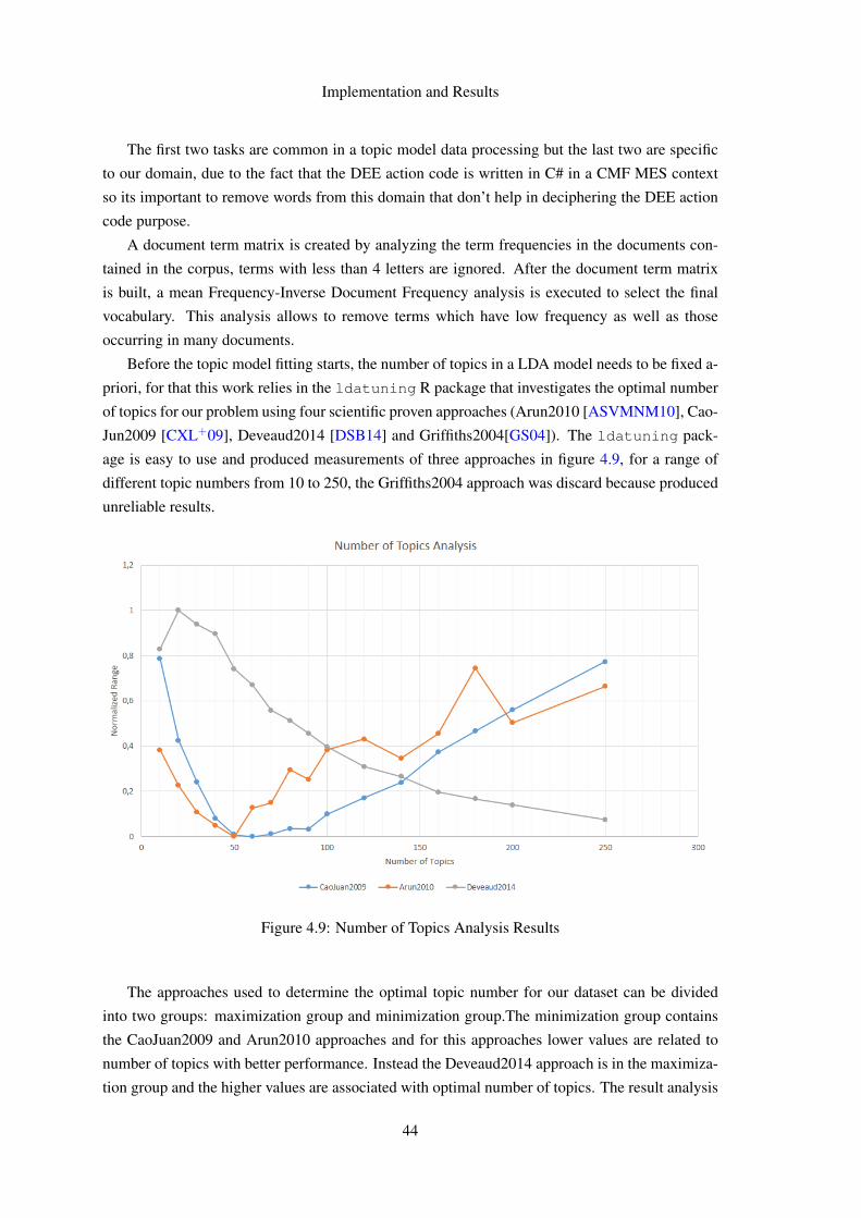
Implementation and Results
The first two tasks are common in a topic model data processing but the last two are specific
to our domain, due to the fact that the DEE action code is written in C# in a CMF MES context
so its important to remove words from this domain that don’t help in deciphering the DEE action
code purpose.
A document term matrix is created by analyzing the term frequencies in the documents con-
tained in the corpus, terms with less than 4 letters are ignored. After the document term matrix
is built, a mean Frequency-Inverse Document Frequency analysis is executed to select the final
vocabulary. This analysis allows to remove terms which have low frequency as well as those
occurring in many documents.
Before the topic model fitting starts, the number of topics in a LDA model needs to be fixed a-
priori, for that this work relies in the ldatuning R package that investigates the optimal number
of topics for our problem using four scientific proven approaches (Arun2010 [ASVMNM10], Cao-
Jun2009 [CXL+09], Deveaud2014 [DSB14] and Griffiths2004[GS04]). The ldatuning pack-
age is easy to use and produced measurements of three approaches in figure 4.9, for a range of
different topic numbers from 10 to 250, the Griffiths2004 approach was discard because produced
unreliable results.
Figure 4.9: Number of Topics Analysis Results
The approaches used to determine the optimal topic number for our dataset can be divided
into two groups: maximization group and minimization group.The minimization group contains
the CaoJuan2009 and Arun2010 approaches and for this approaches lower values are related to
number of topics with better performance. Instead the Deveaud2014 approach is in the maximiza-
tion group and the higher values are associated with optimal number of topics. The result analysis
44
Implementation and Results
demonstrate that the optimal number of topics range is between 20 and 50 topics for this dataset,
the DEE action topic model was built using 40 topics.
The final step in the topic model generation process is the model fitting using the LDA algo-
rithm with 40 topics, thereafter the fitted model is stored in the web application database. Users
interested in searching and discovering existing DEE actions that have a similar topic to the DEE
action they intend to implement can use the web application UI to find the existing DEE actions
inside that topic.
4.2.2 Technologies
The web application that allows users to search for topics was built using the Microsoft technol-
ogy stack: C# programming language, .Net Core Framework and ASP.NET Core. On the other
hand the topic model generation process relied in R programming language packages such as tm,
topicmodels and ldatuning.
C# is a programming language that is designed for building a variety of applications that
run on the .NET Framework. C# is simple, powerful, type-safe, and object-oriented. The many
innovations in C# enable rapid application development while retaining the expressiveness and
elegance of C-style languages.
.NET Core is a general purpose development platform maintained by Microsoft and the .NET
community. It is cross-platform, supporting Windows, macOS and Linux, and can be used in
device, cloud, and embedded/IoT scenarios [Mic17].
ASP.NET Core is a new open-source and cross-platform framework for building modern cloud
based internet connected applications, such as web apps, IoT apps and mobile backends. ASP.NET
Core apps can run on .NET Core or on the full .NET Framework. It was architected to provide an
optimized development framework for apps that are deployed to the cloud or run on-premises. It
consists of modular components with minimal overhead, so you retain flexibility while construct-
ing your solutions [Mic17].
R is a language and environment for statistical computing and graphics. R provides a wide
variety of statistical (linear and nonlinear modelling, classical statistical tests, time-series analysis,
classification, clustering, ...) and graphical techniques, and is highly extensible [Lan17].
4.2.3 Results
The present work was able to built a topic model for the existing DEE actions and enable users to
search for those topics on a web platform. The results of this work represent a new way of devel-
oping support and learning documentation for the development of new DEE actions, requiring a
low investment by the development team in its creation and maintenance.
The web platform in figure 4.10 that constitutes the support and learning documentation has
as main functionality the search of existing DEE actions through the topics of the model but it is
also possible to search the existing DEE actions as well as the words of the actions source codes
considered in the creation of the model.
45

Implementation and Results
Figure 4.10: Web Application UI for topic search
As previously mentioned, this is a work limited by the temporal constraints of a dissertation,
therefore we were only able to build one of the modules of a Collective Knowledge System but
a fully fledged CKS requires a active community and that was unfeasible to gather within the
duration of this work. Thus it is possible to frame the DEE actions topic model in the context
of Collective Knowledge System as a way to emerge knowledge from user-generated content
however this work isn’t able to fully explore the CKS key properties, specially human-machine
synergy and increasing returns with scale.
An active community would allow us to go beyond a topic empirical validation and assess real
world gains of this kind of documentation. In a way, the code editor validation process showed that
this kind of documentation can help the software development process because many participants
in the validation process asked if they could use code from previously implemented DEE actions
and that is exactly what the DEE action topic model tries to simplify and improve.
Figure 4.11: Example of a generated topic (Top 10 words)
4.3 Chapter Summary
This chapter provided an in-depth review of the design decisions and technologies behind the
code editor and the topic model but also and more importantly it presented the work’s results and
46

Implementation and Results
analyzed the dissertation’s goals fulfillment.
The code editor and its requested functionalities were all built, so from an implementation
standpoint, the goals were met. The results of the validation process demonstrated that the new
editor offers better support and faster development.
The topic model for the existing DEE actions enables users to search for topics on a web
platform and constitutes a new way of developing support and learning documentation for the
development of new DEE actions, requiring a low investment by the development team in its
creation and maintenance.
47

Implementation and Results
48

Chapter 5
Conclusions and Future Work
A Manufacturing Execution System manages and oversees the manufacturing operations execution
with high levels of performance and flexibility to the changes of the productive process so that its
users are competitive in their market. But different customers produce different products and
require different functionalities so the system must be customizable and extensible to meet the
customers needs and goals.
A sustainable, customizable and extensible software product combines generic maintenance
and support with a customization framework to enable modifications and additional specific cus-
tomer features. Harmonize generic maintenance and support with specific customer features is a
challenging task.
A software framework can overcome that challenge since it provides a software environment
in which a generic functionality can be overridden, modified or extend by user-written code to
simplify and speed up development of specific customer software. A software framework guaran-
tees a generic application through non-modifiable framework code and inversion of control while
allowing software extensibility and customization.
The cornerstones of an highly adopted and well supported software framework are tools and
documentation although tools may require highly skilled users and long training times and docu-
mentation can be expensive and time consuming.
5.1 Contributions
The main goal of this work was to enhance the software customization process. Those enhance-
ments were:
• A tool that improves the process simplicity and reliability due to displaying intuitively the
compiler code analysis to the user.
49

Conclusions and Future Work
• A new kind of documentation generated using text mining techniques that reduces creation
and maintenance costs.
The browser based code editor and its code analysis features contribute to an more reliable and
efficient software customization process due to its informative and contextual code suggestions and
a real-time code analysis.
The results of the validation process demonstrated that the new editor offers better support and
faster development. Moreover, according to post validation assessment interviews, the most useful
code analysis feature is the code auto-completion suggestions because it doesn’t require the user
to know by heart all the framework classes, methods or parameters and its also an easy and fast
way to provide in line documentation.
The topic model approach to documentation generation demonstrated that it is a path that is
worth pursuing although an empirical validation wasn’t conducted, most topics were meaningful
and helpful in the domain context. With a low creation and maintenance cost, the topic model
offers a new platform to learn how to use a framework.
Both enhancements contributed to an overall software customization process improvement by
means of a faster and reliable development that might increase customer framework adoption.
5.2 Future Work
All dissertation goals were achieved nevertheless is always possible to improved upon our work
and there are always paths left to explore. Therefore, in a future work the following subjects could
be further explored:
• Deepen the customization framework support improvements analysis by gathering an active
community to use and test the topic model. Evaluate the community topic model usage
trends and gains for assessing if a topic model that provides a comprehensive domain cov-
erage translates into effective real-world support documentation.
• As previously stated, it is possible to frame a topic model in the collective knowledge sys-
tems field as a way to emerge knowledge from user-generated content but a fully fledge
CKS requires human-machine synergy and increasing returns with scale. Therefore, build
a collective knowledge system on top of this work’s topic model and gather an active com-
munity that adds the missing CKS properties through an organic user topic rating. In order
to investigate the benefits of a collective knowledge system for software documentation.
• Implement a code editor feature that allows users to compare code differences between two
source code files. A diff editor is an important stepping stone to a customization actions
version control system that stores and displays changes between customization action ver-
sions.
50

References
[ASVMNM10] Rajkumar Arun, Venkatasubramaniyan Suresh, C Veni Madhavan, andM Narasimha Murthy. On finding the natural number of topics with latent dirich-let allocation: Some observations. Advances in Knowledge Discovery and DataMining, pages 391–402, 2010.
[Ber16] Matthias Bertram. The Strategic Role of Software Customization. Springer, 2016.
[Boc16] Jason Bock. .NET Development Using the Compiler API. Springer, 2016.
[CXL+09] Juan Cao, Tian Xia, Jintao Li, Yongdong Zhang, and Sheng Tang. A density-based method for adaptive lda model selection. Neurocomputing, 72(7):1775–1781, 2009.
[dA03] Ademar Manuel Teixeira de Aguiar. Framework Documentation - A MinimalistApproach. PhD thesis, Faculdade de Engenharia da Universidade do Porto, Porto,Portugal, 2003.
[Dic17] James Dickman. Topic modeling explained: Lda to bayesian infer-ence. Published in https://www.tdktech.com/tech-talks/topic-modeling-explained-lda-to-bayesian-inference, Jan-uary 2017.
[DSB14] Romain Deveaud, Eric SanJuan, and Patrice Bellot. Accurate and effective la-tent concept modeling for ad hoc information retrieval. Document numérique,17(1):61–84, 2014.
[dSPS12] Maria Clara dos Santos Pinto Silveira. A reutilização de requisitos no desenvolvi-mento e adaptação de produtos de software. 2012.
[GH11] Bettina Grun and Kurt Hornik. topicmodels: An r package for fitting topic mod-els. Journal of Statistical Software, 2011.
[Gru07] Tom Gruber. Collective knowledge systems: Where the social web meetsthe semantic web. Published in https://tomgruber.org/writing/collective-knowledge-systems.htm, November 2007.
[GS04] Thomas L Griffiths and Mark Steyvers. Finding scientific topics. Proceedings ofthe National academy of Sciences, 101(suppl 1):5228–5235, 2004.
[Had05] Basil Hadjimichael. Manufacturing Execution Systems Integration and Intelli-gence. PhD thesis, Department of Eleetrical and Computer Engineering - McGiliUniversity, Montreal, Canada, 2005.
51

REFERENCES
[Lan17] R Language. What is r? Published in https://www.r-project.org/about.html, June 2017.
[LS16] Eric Leland and Jason Salter. Customizing Software and Services. FivePathsLLC, 2016.
[Man17a] Critical Manufacturing. Critical manufacturing framework. Pub-lished in http://www.criticalmanufacturing.com/en/critical-manufacturing-mes/architecture, January 2017.
[Man17b] Critical Manufacturing. Critical manufacturing mes - the future of manufacturingexecution systems. Published in http://www.criticalmanufacturing.com/en/critical-manufacturing-mes/overview, January 2017.
[Man17c] Critical Manufacturing. Customization guide. 2017.
[Man17d] Critical Manufacturing. Manufacturing execution systems- empowering operations. Published in http://www.criticalmanufacturing.com/en/critical-manufacturing-mes/what-is-manufacturing-execution-system, January 2017.
[Man17e] Critical Manufacturing. Modular functionality for integrated management of op-erations. Published in http://www.criticalmanufacturing.com/en/critical-manufacturing-mes/modules-features, January 2017.
[Mic17] Microsoft. Introduction to asp.net core. Published in https://docs.microsoft.com/en-us/aspnet/core/, June 2017.
[Net17] Mozilla Developer Network. Web technology for developers. Published inhttps://developer.mozilla.org/en-US/docs/Web/, May 2017.
[SA01] Firmino Silva and J. Alves. ERP e CRM: da empresa à e-empresa: soluções deinformação reais para empresas globais. Edições Centro Atlantico, 2001.
[Saa17] Mehrdad Saadatmand. Towards automating integration testing of .net applica-tions using roslyn. The 2017 IEEE International Conference on Software Quality,Reliability and Security QRS 2017, 25 Jul 2017, Prague, Czech Republic, 2017.
[Sin05] Sinfic. O ciclo de vida de um sistema integrado de gestão. Disponívelem http://www.sinfic.pt/PortalWeb/newsletter/sinfic/Newsletter29/Dossier3.CicloVidaDosERP.html, 2005.
[Uhl16] Kasey Uhlenhuth. .net compiler platform (“roslyn”) overview. 2016.
[Vas16] Sergey Vasiliev. Introduction to roslyn and its use in program development. Pub-lished in https://www.viva64.com/en/b/0399/, May 2016.
52