Embed Size (px)
Citation preview

I
TONI SIIK
THE VERIFICATION OF LOW-PRESSURE DIE CASTINGSIMULATION RESULTS
Master’s Thesis
Examiner: Professor Tuomo Tiainen
Examiner and topic approved in the Faculty ofAutomation, Mechanical and MaterialsEngineering Council meeting on 5.10.2011
II
ABSTRACT
TAMPERE UNIVERSITY OF TECHNOLOGY
Master’s Degree Programme in Materials Engineering
SIIK, TONI: The verification of low-pressure die casting simulation results
Master of Science Thesis, 56 pages
November 2011
Major: Metals
Examiner: Professor Tuomo Tiainen
Keywords: low-pressure die casting, simulation, verification, heat transfercoefficients, material data, brass, MAGMASOFT
In this thesis the accuracy of low-pressure die casting simulation results is bothverified and improved for the casting process at Oras Oyj. The accuracy of castingsimulation depends on the correctness of the initial data used for the simulation. Thisdata include the process parameters and material data. As casting simulation programsonly usually provide a limited database for the materials available on purchase it is oftennecessary to expand this database by modeling more materials and providing the correctprocess parameters of the simulated process.
The main goal of this project was to verify the correctness of the most importantprocess parameters, material data and the actual results. With correct values thesimulations can provide valuable information to the product designers and production.This information can be used to design better products and molds from the conceptstage forwards. The simulation results can be used to improve old products.
The project was divided into two separate parts, theoretical and experimentalsections. The theoretical section of the project concentrated on providing backgroundinformation on the data which needed to be verified.
During the experimental section of the project, data was acquired which could beused to tune the simulation program. The data on casting alloys were improved bysimulating the materials properties which were needed. These simulated properties wereverified by using the thermal analysis of the casting alloys. The mold materials were
III
tested at Jönköping University for the needed properties. All of these measurementswere used to model the casting alloys and mold materials into the simulation programsdatabase.
An experimental mold was also manufactured; this mold was used to measure thetemperature-time curves inside the mold material during the casting cycles. The moldwas used to cast test-castings of each different casting alloy which had to be simulated.The thermal data acquired from these test castings was compared to the simulatedthermal data and the simulation program was adjusted until the results were comparable.
The accuracy of the simulation results was increased significantly due to theimproved data acquired during this project. After this project simulation can be used asa tool in tool design and in finding the sources of quality problems. The data can still beimproved by comparing the simulation results of more cases to the results obtained fromreal castings.
IV
TIIVISTELMÄ
TAMPEREEN TEKNILLINEN YLIOPISTO
Materiaalitekniikan koulutusohjelma
SIIK, TONI: Matalapainevalun simulointitulosten verifiointi
Diplomityö, 56 sivua
Marraskuu 2011
Pääaine: Metallit
Tarkastaja: professori Tuomo Tiainen
Avainsanat: Matalapainevalu, simulointi, verifiointi, materiaali data,lämmönsiirtokerroin, messinki, MAGMASOFT
Tässä diplomityössä sekä varmennettiin että parannettiin Oras Oyj:nmatalapainevalu-prosessin simulointitulosten tarkkuutta. Simulointien tarkkuus riippuupitkälti simulointiohjelmistoon syötettävien alkutietojen tarkkuudesta. Nämä tiedotsisältävät sekä prosessiparametrit että materiaalidatan. Useimmissa tapauksissavalunsimulointiohjelmistot sisältävät suoraan jonkin laajuisen materiaali- japrosessiparametri-tietokannan, mutta usein tätä tietokantaa on laajennettavamallintamalla sinne uusia materiaaleja ja lisäämällä todellisen prosessinprosessiparametreja.
Tämän projektin pää-tavoitteena on ollut varmentaa Oras Oyj:n valuprosessintärkeimmät parametrit, käytetty materiaalidata sekä tulokset. Oikein kalibroitunavalunsimulointia voidaan käyttää työkaluna valujensuunnittelussa ja tuotannossa.Simuloinneista saatavaa tietoa voidaan käyttää hyväksi paremmin valmistettavientuotteiden suunnittelussa aina konsepti-tasolta lähtien. Vaihtoehtoisestisimulointituloksia voidaan käyttää vanhojen tuotteiden valmistettavuudenparantamiseksi.
Tämä projekti voidaan jakaa kahteen eri osaan, teoreettiseen osaan ja käytännönosaan. Teoreettisessa osassa pyrittiin keräämään taustatietoa varmennettavista tiedoista.
Kokeellisessa osassa hankittiin ja mitattiin tarvittavaa tietoa simulointiohjelmistonhienosäätöä varten. Valettavien seosten ominaisuuksia ja tietoja parannettiin

V
simuloimalla materiaaleja niiden ominaisuuksien tarkentamiseksi. Nämä simuloiduttulokset varmennettiin termisen analyysin keinoin. Muottimateriaalit testattiinJönköpingin Yliopistossa. Kaikki hankittu tieto käytettiin ohjelmiston tietokannanpäivittämiseen.
Projektia varten valmistettiin myös instrumentoitu koemuotti, jonka avulla pystyttiinmittaamaan lämpötiloja muottilaattojen sisältä valusyklien aikana.Simulointiohjelmistoa hienosäädettiin tämän jälkeen kunnes simuloidut tulokset saatiinvastaamaan mitattua lämpötilatietoa.
Simulointitulosten tarkkuus parani projektin johdosta huomattavasti. Projektinansiosta simulointia voidaan käyttää paremmin työkaluna niin tuotteiden kuintyökalujenkin suunnittelussa sekä valuongelmien ratkaisussa Oras Oyj:n prosessissa.Tuloksia voidaan jatkossa parantaa tarkentamalla edelleen ohjelmiston parametreja.Tämä voidaan tehdä vertaamalla simulointituloksia valettuihin kappaleisiin.

VI
PREFACE
First of all, I want to thank everybody at Oras Oyj. for providing this interestingproject for me to work on and for all of their support. I am also very grateful for theguidance, knowledge and feedback I have received from Professor Tuomo Tiainenduring this project. I would not even have become interested in this field of studieswithout the interesting courses held by Tuomo.
Most of all I would like to thank my family and friends for their support andencouragement received during this project. Without you I would not be here today.
Tampere 2011
TONI SIIK

VII
TABLE OF CONTENTS
ABSTRACT............................................................................................................... II
TIIVISTELMÄ .........................................................................................................IV
PREFACE .................................................................................................................VI
ABBREVIATIONS AND NOTATIONS .................................................................. X
1 Introduction ........................................................................................................1
THEORETICAL BACKGROUND ............................................................................3
2 Low-pressure die casting (LPDC) ......................................................................3
2.1 Advantages of the process...........................................................................3
2.2 The process..................................................................................................4
2.3 Future development.....................................................................................6
3 Casting and mold materials ................................................................................8
3.1 Copper alloys ..............................................................................................8
3.1.1 Castability of copper base alloys.............................................................9
3.1.2 Main alloying elements in copper alloys...............................................10
3.2 Casting alloys – Brass alloys ....................................................................12
3.2.1 Yellow brass (CuZn36Pb1) ...................................................................13
3.2.2 Low lead yellow brass ...........................................................................13
3.2.3 Other nonleaded yellow brasses ............................................................14
3.3 Mold materials in low pressure die casting...............................................15
3.3.1 CuCrZr – alloys .....................................................................................15
3.3.2 Beryllium copper alloys ........................................................................16
3.3.3 Safe handling of beryllium containing alloys........................................17
4 Casting simulation ............................................................................................18

VIII
4.1 The basic principles of casting simulation ................................................18
4.1.1 Pre-processing .......................................................................................19
4.1.2 Simulation .............................................................................................22
4.1.3 Post-processing......................................................................................24
5 Test mold design for experimental studies.......................................................26
5.1 Geometry design principles.......................................................................26
5.1.1 Casting design .......................................................................................26
5.1.2 Gating design.........................................................................................26
5.2 Instrumentation design principles .............................................................27
5.2.1 Thermocouple placement ......................................................................28
6 Improving the accuracy of simulation results ..................................................29
EXPERIMENTAL STUDIES...................................................................................31
7 Studies on material data ...................................................................................31
7.1 Casting alloys ............................................................................................31
7.1.1 Theoretical models of copper alloys .....................................................32
7.1.2 Verification of the simulated properties by thermal analysis ................33
7.2 Mold materials ..........................................................................................35
7.2.1 Specific heat capacity ............................................................................35
7.2.2 Density...................................................................................................36
7.2.3 Thermal diffusivity................................................................................36
7.3 Core materials ...........................................................................................38
7.3.1 Comparative testing of the thermal conductivity in sand materials ......38
7.3.2 The setup of experiments ......................................................................38
7.3.3 Results ...................................................................................................40
8 Casting experiments .........................................................................................43
8.1 Manufacture of the test mold ....................................................................43

IX
8.1.1 Machining the mold...............................................................................43
8.1.2 Instrumentation of the mold ..................................................................43
8.1.3 Mold setup.............................................................................................46
8.2 The casting experiments............................................................................46
9 Results of improved material data and process parameters..............................49
9.1 Improved material data and process parameters .......................................49
9.1.1 Casting alloys ........................................................................................49
9.1.2 Mold materials.......................................................................................49
9.1.3 Core materials........................................................................................49
9.1.4 Heat transfer coefficients.......................................................................50
9.2 Simulation setup........................................................................................51
9.3 Further verification of the simulation results ............................................52
10 Conclusions ......................................................................................................53
10.1 Future areas of research ............................................................................53
10.1.1 Improvements to simulation accuracy ...............................................53
10.1.2 Improvements for process control and management .........................54
11 References ........................................................................................................55

X
ABBREVIATIONS AND NOTATIONS
LPDC - Low-pressure die casting
HTC - Heat transfer coefficient
FEM - Finite element method
FVM - Finite volume method
MAGMASOFT - A casting simulation software suite
ASM - American Society of Metals
UNS - Unified numbering system to identify different alloys
DSC - Differential Scanning Calorimetry

1
1 INTRODUCTION
This Master of Science thesis was a part of a Tekes-funded project, which wasaiming to implement the use of casting simulation in the production of yellow brasscastings at Oras Oyj. The main goal of the thesis was to verify the simulation resultsobtained with the software and to take the necessary steps to improve the accuracy ofthe simulation results.
Casting simulation is an FVM-based technique which can be used to simulate andforecast the filling of the mold, solidification and properties of castings. Castingsimulations have become more common as the calculation times for the simulationshave decreased with the increased computational power of workstations and clusters.The decreased calculation times for the simulations have made it possible to increasethe accuracy of the simulations so that even smaller details of the casting process can besimulated. The increased accuracy of simulation results can be used to improve thecasting design, improve the yields of castings, and to improve the casting quality. Whenall of these are achieved, significant savings can be expected.
While casting simulation programs usually include some process data database, atleast some of the parameters and values of the casting processes are individual in eachfoundry. In addition foundries often use in their process materials which are notincluded in the database which leads to the need to describe those materials into theprograms database. While most values and parameters in the casting process can beapproximated, either by mathematical models and approximations, measuring the actualprocess parameters and values usually provides much better results.
The experimental part of the thesis included the description of two casting alloysand two mold materials into MAGMASOFT. The casting alloy models developed forthe database were based on mathematical models of the alloys, which were calculatedfor the two alloy compositions used at the foundry. These mathematical models wereverified by thermal analysis. The two mold materials were described using the results ofactual measurements performed on actual samples of each material.
An instrumented test mold was produced for the project with the goal of providingmeasurement data which could be used to determine the heat transfer coefficients(HTCs) for the several different material interfaces existing in the system.

2
The data acquired from the test mold was used to fine-tune the HTC-values withinthe simulation program so that the simulated data from the software was as close aspossible to the data measured from the test-mold.
The results of this thesis were used to fine-tune the simulation program at the clientfor their process so that it would provide them with accurate simulation results. Thiscould be used as a good tool in helping design decisions and to fine-tune the castingsystems.
3
THEORETICAL BACKGROUND
2 LOW-PRESSURE DIE CASTING (LPDC)
Low-pressure die casting is one of the permanent mold castings techniques, whichhas been used since the 1950s. It is commonly used as a production technique for high-volume, high-quality and high-integrity components from nonferrous metals such asaluminum, magnesium and many copper base alloys. Aluminum is the most used alloywith the LPDC-technique. With aluminum some of the most common applications arecritical components for the automotive industry, such as engine blocks, wheels andsuspension components. The casting weight is usually between 5 kg and 100 kg, butboth smaller and larger castings are possible. When casting copper base alloys such asbrass, one of the most common applications are plumbing components, such as valves,faucets and water meter bodies. (Bader 2002) (Woycik and Peters 2008)
2.1 Advantages of the process
The casting technique is well suited to many components with large- to medium-sizeseries where casting quality is important. One of the main advantages of the process isthe highly controllable filling of the mold cavities, which in turn makes the filling of themold as non-turbulent and as smooth as possible.
This results in usually 5-6% better mechanical properties when compared withsimilar castings produced with gravity casting techniques from the same alloys. One ofthe reasons for the improved mechanical properties is the lack of entrained oxide films,which is resulting from the smooth filling of the cavities. The presence of the oxidefilms is further reduced by the fact that the melt which is forced into the mold is takeninside the melt in the furnace. This eliminates the oxide films which are most commonlyfound on the melt surface at the upper part of the furnace. The highly-controlled fillingalso results in a very low rejection rate.
Another significant advantage of the process is that the riser volume of the castingscan be minimized with correct casting design. When casting systems are designed sothat the final solidification of the casting moves from the top of the product to the gatingsystem, it may be possible to leave out risers completely. The lack of risers will improve

4
the yield of the castings significantly and it will also lower the manufacturing costs ofthe castings as less work will be required for the cleaning of the castings.
The reason why low-pressure die casting is one of the best casting techniques forcasting brass plumbing components, such as faucets and valves, is that the techniqueallows for complex external and internal shapes. They are possible to obtain with theuse of sand cores. As a large portion of brass castings will end up with finishing bygrinding, polishing and chromium plating, low-pressure die casting also provides thehigh casting quality which is needed for these components. Due to the long productionprocess the faults which are found in the last stages of manufacturing, become veryexpensive. With correct mold design and good process control, the faults whichoriginate in the casting stage can be minimized. (Bader 2002) (Woycik and Peters 2008)(Campbell 2003)
2.2 The process
Low-pressure die casting machines are highly automated and usually require onlyone operator for each machine. The operator takes care of starting the casting cycle, ofinspecting the castings, and of inserting the necessary cores. Depending on the moldstructure, the operator may also be responsible for removing the castings from themolds. Ideally the process parameters should be established well before the molds areused in production, but often the operators are also responsible for adjusting the processparameters when necessary.
Figure 1 - The basic structure of a LPDC-machine. (Campbell 2003)
The LPDC machines most often have a general structure which can be seen inFigure 1. The machines consist of the mold structure and a hermetically sealed furnace.Depending on the casting machine the mold can have either a vertical or a horizontalparting line. The basic working principle of both machine types is similar, but the mold
5
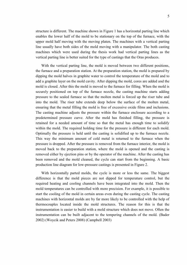
structure is different. The machine shown in Figure 1 has a horizontal parting line whichenables the lower half of the mold to be stationary on the top of the furnace, with theupper mold half moving with the moving platen. The machines with a vertical partingline usually have both sides of the mold moving with a manipulator. The both castingmachines which were used during the thesis work had vertical parting lines as thevertical parting line is better suited for the type of castings that the Oras produces.
With the vertical parting line, the mold is moved between two different positions,the furnace and a preparation station. At the preparation station, the mold is prepared bydipping the mold halves in graphite water to control the temperature of the mold and toadd a graphite layer on the mold cavity. After dipping the mold, cores are added and themold is closed. After this the mold is moved to the furnace for filling. When the mold issecurely positioned on top of the furnace nozzle, the casting machine starts addingpressure to the sealed furnace so that the molten metal is forced up the riser tube andinto the mold. The riser tube extends deep below the surface of the molten metal,ensuring that the metal filling the mold is free of excessive oxide films and inclusions.The casting machine adjusts the pressure within the furnace enclosure according to apredetermined pressure curve. After the mold has finished filling, the pressure isretained for a needed amount of time so that the metal has enough time to solidifywithin the mold. The required holding time for the pressure is different for each mold.Optimally the pressure is held until the casting is solidified up to the furnace nozzle.This way the minimum amount of cold metal is returned to the furnace when thepressure is dropped. After the pressure is removed from the furnace interior, the mold ismoved back to the preparation station, where the mold is opened and the casting isremoved either by ejection pins or by the operator of the machine. After the casting hasbeen removed and the mold cleaned, the cycle can start from the beginning. A basicproduction line diagram for low-pressure castings is presented in Figure 2.
With horizontally parted molds, the cycle is more or less the same. The biggestdifference is that the mold pieces are not dipped for temperature control, but therequired heating and cooling channels have been integrated into the mold. Then themold temperatures can be controlled with more precision. For example, it is possible tostart the cooling of the mold in certain areas even during the casting cycle. The castingmachines with horizontal molds are by far more likely to be controlled with the help ofthermocouples located inside the mold structures. The reason for this is that theinstrumentation is easier to build with a mold structure which does not move. Often theinstrumentation can be built adjacent to the tempering channels of the mold. (Bader2002) (Woycik and Peters 2008) (Campbell 2003)

6
Figure 2 - Low pressure die casting production line. (Bader 2002)
2.3 Future development
While low-pressure die casting is one of the most reliable casting techniques forhigh quality parts there are several areas with room for improvement. One of the mainareas where the improvements are significant issues is the insufficient melt velocitycontrol. Often filling rates are increased to improve the cycle times. While the higherfilling rates may lower the cycle time, the benefits are outweighed by the problems thiscauses.
There are some visions how this issue can be solved. The computerized control ofthe casting machines often makes it possible to use optimized pressure curves for filling.When the pressure curves are optimized correctly, filling speeds are optimal at eachpoint of filling. The optimized filling curves are still not common as this optimization isnot easy. It is challenging to determine the actual rate by which the mold is filledwithout the use of instrumented molds. This causes the optimized pressure curves oftento get out of phase, causing even more problems than the non-optimized pressurecurves.
In the future we may see more molds, where it is possible to determine the rate offilling in real-time through the use of probes. John Campbell suggests that this could becarried out by monitoring the pressures of the inert gases above the mold and by

7
measuring the changing capacitance between the melt and mold clamp plate. (Campbell2003)
Another possible area of improvement in low-pressure die casting is the diecoatings. When casting copper base alloys with low-pressure die casting the molds aretraditionally coated with graphite. Now new coatings are becoming available whichimprove the control over the heat transfer from the melt to the mold. Better coatingmaterials will improve both the quality of the castings and the control of the castingprocess.

8
3 CASTING AND MOLD MATERIALS
3.1 Copper alloys
Copper alloys can be divided into six different groups by their composition. Thegroups include coppers, high-copper alloys, brasses, bronzes, copper nickels and nickelsilvers. The coppers contain less than 0.7% of other elements than copper while thehigh-copper alloys can contain up to 8% of alloying elements. The main alloyingelements and their contents in the other copper alloy groups can be seen in Table 1.
Table 1 - Different copper base alloy groups and their main alloying elements. (Sadayappan,Sahoo and Michels 2008)
All of the different copper alloys are considered as castable, but the castable alloyshave different standards which allow for different compositions than the wrought alloys.Most of the compositional differences are due to efforts to improve the castability of thealloys. The more accurate division of the alloys can be seen in Table 2.

9
Table 2 - Copper base alloys and their UNS-standard numbers. (Sadayappan, Sahoo andMichels 2008)
3.1.1 Castability of copper base alloys
Castability is a term which tries to establish how easy the alloys are to use in castingprocesses. For an alloy to be considered as castable it must be relatively easy to producesound castings with that alloy. All copper alloys can be cast using sand castingtechnique, but only some of the alloys are commonly used in die casting. Pressurizeddie casting is mainly used to cast different yellow brass grades, for which the techniqueis well suited. The castability ratings (according to ASM) of some of the casting alloyscan be found in Table 3.
Generic name UNS numbers Composition
Coppers C10100-C15760 >99% Cu
High-copper a l loys C16200-C19600 >96% Cu
Brasses C20500-C28580 Cu-Zn
Leaded brasses C31200-C3890 Cu-Zn-Pb
Tin brasses C40400-C49080 Cu-Zn-Sn-Pb
Phosphor bronzes C50100-C52400 Cu-Sn-P
Leaded phosphor bronzes C53200-C54800 Cu-Sn-Pb-PCopper-phosphorus and copper-s i lver-phosphorus a l loys
C55180-C55284 Cu-P-Ag
Aluminum bronzes C60600-C64400 Cu-Al -Ni -Fe-Si -Sn
Si l i con bronzes C64700-C66100 Cu-Si -Sn
Other copper-zinc a l loys C66400-C69900 …
Copper-nickels C7000-C79900 Cu-Ni -Fe
Nickel s i lvers C73200-C79900 Cu-Ni -Zn
Coppers C80100-C81100 >99% Cu
High-copper a l loys C81300-C82800 >94 Cu
Red and leaded red brasses C83300-C85800Cu-Zn-Sn-Pb(75–89% Cu)
Yel low and leaded yel low brasses C85200-C85800Cu-Zn-Sn-Pb(57–74% Cu)
Manganese bronzes and leadedmanganese bronzes
C86100-C86800 Cu-Zn-Mn-Fe-Pb
Si l i con bronzes , s i l i con brasses C87300-C87900 Cu-Zn-Si
Tin bronzes and leaded tin bronzes C90200-C94500 Cu-Sn-Zn-Pb
Nickel -tin bronzes C94700-C94900 Cu-Ni -Sn-Zn-Pb
Aluminum bronzes C95200-C95810 Cu-Al -Fe-Ni
Copper-nickels C96200-C96800 Cu-Ni -Fe
Nickel s i lvers C97300-C97800 Cu-Ni -Zn-Pb-Sn
Leaded coppers C98200-C98800 Cu-Pb
Miscel laneous a l loys C99300-C99750 …
Wrought alloys
Cast alloys

10
Table 3 - Castability rating of copper alloys according to ASM. The ratings go from 1 to 8 with 1being the best rating and 8 the worst. (Sadayappan, Sahoo and Michels 2008)
3.1.2 Main alloying elements in copper alloys
Zinc
Zinc is the most used alloying element in copper alloys due its low price and solid-solution strengthening properties. It both lowers the alloy price and adds strength andhardness at the same time. Contents up to 36 wt.-% can be used to produce alloys whichhave a single-phase structure which is called alpha brass. When the zinc content ishigher, the structure of the alloy turns to alpha-beta brass.
Tin
Tin is the oldest alloying element found in copper base alloys. It has by far higherstrengthening effect on the alloys when compared to zinc. It also improves the

11
corrosion-resistance and enhances the castability by increasing the fluidity andsolidification range of the alloys. Tin is used in copper alloys up to the content of 11.5wt.-%.
Lead
Lead is a common alloying element found in many copper alloys even though it isinsoluble in copper. The lead found in these alloys forms a separate phase whichsolidifies last. Due to this behavior it is found in the grain boundaries and interdendriticareas.
Lead is used in the alloys for many different reasons. It has been found to improvethe soundness of castings for example by filling the pores which form duringsolidification. This makes it easier to produce pressure-tight castings. High-lead alloysare also used in bearings, where the added lead improves the tribological aspects of thealloys. In the bearings the lead acts as a dry lubricant. Machinability is also improvedwith the addition of lead as the lead phases work as natural chip breakers.
Aluminum
Aluminum is used in copper alloys with contents up to 9 wt.-%. Aluminumstrengthens the alloys by solid solution strengthening and therefore it is used in thehigh-strength alloys. When aluminum is added in small amounts, it also improves themelt fluidity of some of the copper alloys such as the yellow and silicon brasses.
Silicon
Silicon containing alloys are commonly used in art castings as the silicon increasesthe melt fluidity of the alloys. Contents of up to 5 wt.-% are used.
Nickel
Nickel is found in the copper-nickel alloys which exhibit high resistance tocorrosion. The copper-nickel alloys are commonly used in the petroleum, chemical,food and dairy industries. Nickel additions in copper alloys also improve the strengthand creep resistance. Nickel is also slightly better in improving the pressure tightness ofcastings than lead when used in bronze and semi-red brass alloys.
Beryllium
Beryllium strengthens the copper alloys by providing an interdendritic precipitate.The increased strength comes with a loss in electrical and thermal conductivity and theductility of the alloys. Typically the electrical conductivity of commercial Cu-Be alloysis of the order of 15-20% IACS, where 100% IACS represents the electricalconductivity of 100% pure copper.

12
Chromium
Chromium is used as a strengthening agent in the alloys. Chromium additions lowerthe thermal and electrical conductivities only slightly when compared with pure copperalloys.
Iron
Iron is one of the nonsoluble alloying elements used in copper alloys. Its exactinfluencing mechanism is not well known, but iron is used as a grain refiner in brassesand aluminum bronzes. Iron increases the melting temperature of the alloys and thetendency of hard spot formation. It also increases the strength of the alloys. If magneticsusceptibility has to be considered the iron content should be less than 0.01 wt.-%.
Antimony
Antimony is used in small amounts in brasses to encounter then dezincificationprocess where the zinc evaporates from the molten alloys. When present in tin bronzes,it reduces the strength and ductility.
Bismuth
Bismuth is considered to be an impurity in the high-strength alloys where only 0.01wt.-% of bismuth can cause embrittlement. It is also used to replace lead in some of thebrass alloys where it improves the machinability and pressure tightness of the alloys.Bismuth is used to replace the lead in the alloys as it is less hazardous to the healthwhen compared to lead.
3.2 Casting alloys – Brass alloys
Brasses are one group of the many different copper base alloys. All brass alloyshave zinc as their main alloying element. In addition to zinc the brasses may contain tin,lead, iron, aluminum, nickel, silicon and bismuth. The brasses are divided into manydifferent categories depending on their composition. (Sadayappan, Sahoo and Michels2008)
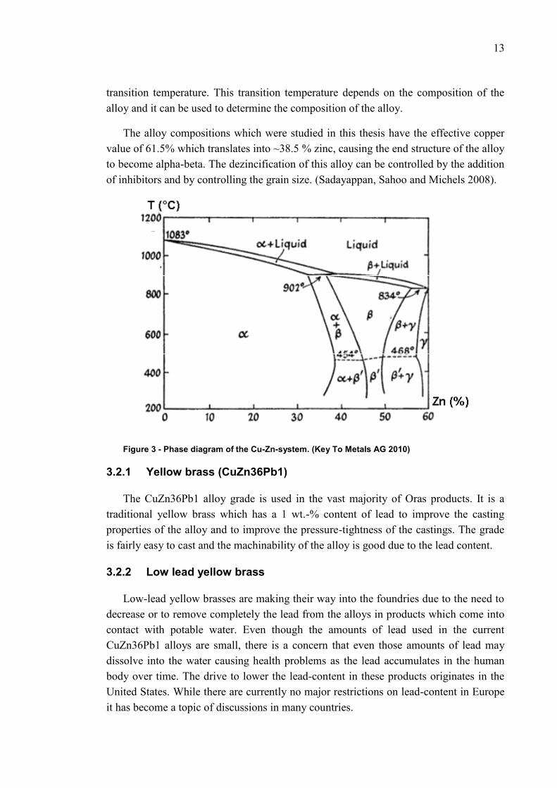
As all brasses have zinc as the main alloying element the phase diagram in Figure 3shows the main phases which can be found in brasses. The alloys whose behavior isstudied in this thesis are located between 35 and 40 wt.-% contents of zinc. As evidentfrom the diagram, the solidification of the alloy starts at higher temperatures with theformation of the alpha phase. After the peritectic solidification temperature has beenreached the beta phase will form together with the alpha phase. With the alloys inquestion the end phase for the brass will stay within the alpha area. The beta phase willchange back to the alpha phase as the temperature of the alloy drops below the
13
transition temperature. This transition temperature depends on the composition of thealloy and it can be used to determine the composition of the alloy.
The alloy compositions which were studied in this thesis have the effective coppervalue of 61.5% which translates into ~38.5 % zinc, causing the end structure of the alloyto become alpha-beta. The dezincification of this alloy can be controlled by the additionof inhibitors and by controlling the grain size. (Sadayappan, Sahoo and Michels 2008).
Figure 3 - Phase diagram of the Cu-Zn-system. (Key To Metals AG 2010)
3.2.1 Yellow brass (CuZn36Pb1)
The CuZn36Pb1 alloy grade is used in the vast majority of Oras products. It is atraditional yellow brass which has a 1 wt.-% content of lead to improve the castingproperties of the alloy and to improve the pressure-tightness of the castings. The gradeis fairly easy to cast and the machinability of the alloy is good due to the lead content.
3.2.2 Low lead yellow brass
Low-lead yellow brasses are making their way into the foundries due to the need todecrease or to remove completely the lead from the alloys in products which come intocontact with potable water. Even though the amounts of lead used in the currentCuZn36Pb1 alloys are small, there is a concern that even those amounts of lead maydissolve into the water causing health problems as the lead accumulates in the humanbody over time. The drive to lower the lead-content in these products originates in theUnited States. While there are currently no major restrictions on lead-content in Europeit has become a topic of discussions in many countries.

14
The low-lead alloys have different properties when compared with the currentlyused alloys. The liquidus and solidus temperatures of the most low-lead alloys arehigher than those of the conventional lead containing alloys. Due to the higher meltingand solidification temperatures, the casting temperature control becomes even morecrucial. The lack of lead also seems to cause a need for a higher degree of feeding of thealloys, which can be seen as bigger feeding pores in the cast components. The lack oflead also makes it harder to produce pressure-tight castings as there is no phase whichwould fill in the pores which are formed when the alloy solidifies. The higher solidusand liquidus temperatures also often cause the low-lead alloys to solidify too earlyduring the casting cycle. This behavior leads to filling and quality problems.
The machinability of the low-lead yellow brasses is often also worse than that of theleaded alloys. This is caused by the lack of chip breaking inclusions and dry lubricantwithin the alloy structure.
3.2.3 Other nonleaded yellow brasses
There are many alloys currently available to the industry where the lead in thebrasses has been replaced with other alloying elements. As mentioned earlier, bismuthhas been used to replace the lead in the casting alloys for health and environmentalreasons. While bismuth still has toxic properties (Figure 4), they are less significant andbismuth does not accumulate in the human body. This makes it safer for use inplumbing applications where there is a possibility that some of the alloying elements aredissolved in the water over long periods of time.
The addition of bismuth to the alloys may cause embrittlement due to its tendency toaccumulate at grain boundaries. This tendency can be avoided if the zinc-concentrationsof the alloys are sufficiently high. (La Fontaine and Keast 2006)
Figure 4 - The toxicity of several different elements. (Kondracki and Szajnar 2007)

15
3.3 Mold materials in low pressure die casting
As the vast majority of low-pressure die casting components are produced fromaluminum the most common mold materials are different tool steels. While steel may bethe optimal material for aluminum casting, in copper alloy casting the temperatures aretoo high for the steel molds. The steel molds wear down too fast.
Carbon steel molds are suitable for copper alloy castings only when the annualcasting volumes are low enough. The approximate expected lifetime of a carbon steelmold is only about 5000 castings according to one of the casting machinemanufacturers. The main reason for the short lifetimes of carbon steel based molds,when used to cast copper base alloys, is caused by the materials lower thermalconductivity. The lower thermal conductivity of the material causes larger temperaturedifferences within the mold, causing tearing in the molds. The wear properties of thecarbon steel molds would be much better than those of copper alloy molds. (Bader2002)
Copper alloy based molds are by far more suitable for casting copper alloys, as theylast much longer. The most common mold material when casting copper alloys isberyllium copper, which usually provides a lifetime of 50 000 castings. In addition thecopper base alloy molds can be reworked several times, providing even an even betterlifetime with minimal added costs. Often the copper molds also produce better qualitycastings, which is crucial when producing consumer products where the surfaces of thecastings will often, are polished and electrically coated with chrome. The influence ofthe mold material should however not be the determining factor in the quality ofcastings as good casting quality should come from good casting design. (Bader 2002)
3.3.1 CuCrZr – alloys
CuCrZr-alloys are precipitation hardenable high-copper alloys where the hardness,thermal and electrical conductivities are still at a high level. This set of properties makesthe material ideal for applications where high strength and excellent thermal andelectrical conductivities are required. The most common applications of the materialinclude welding tips and electrodes for spot welding and spark erosion and parts inelectrical equipment which are subjected to high stresses, but still require high electricalconductivity. (Metaal n.d.)
The alloying elements present in the CuCrZr-alloys are chromium and zirconium.Chromium is added to the alloy to improve the strength of the alloy while lowering theelectrical and thermal conductivities only slightly. Zirconium is added to the alloys toprovide strength through precipitation hardening. (Sadayappan, Sahoo and Michels2008) (MatWeb n.d.)
16
When comparing the CuCrZr-alloys to the beryllium copper alloys, they offer betterelectrical and thermal conductivity, but have smaller strength and hardness. Theimproved thermal conductivity can also be seen as a disadvantage of the material whenused as a mold material. When the material has higher thermal conductivity, it removesheat from the molten metal faster, making the castings to solidify faster. This makes itharder to fill the molds as the melt often cools down too fast. The heat transfer from themolten metal to the mold can be adjusted by using die coatings which lower the heattransfer between the mold and molten metal.
The higher thermal conductivity of this material can also cause hot-tearing in thebrass castings. While the exact reason for this behavior is not known, it is suspected thatit may be caused by the steep temperature gradients in the casting while it is solidifying.This tendency can be decreased by using die coatings which lower the heat transferfrom the melt to the mold.
The CuCrZr-alloys are used at Oras due to the health risks adjacent to the use ofberyllium copper alloys.
3.3.2 Beryllium copper alloys
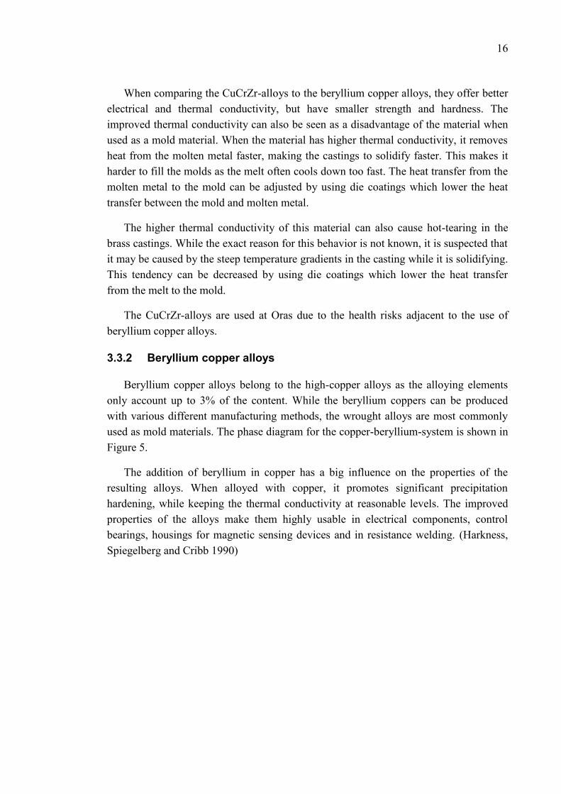
Beryllium copper alloys belong to the high-copper alloys as the alloying elementsonly account up to 3% of the content. While the beryllium coppers can be producedwith various different manufacturing methods, the wrought alloys are most commonlyused as mold materials. The phase diagram for the copper-beryllium-system is shown inFigure 5.
The addition of beryllium in copper has a big influence on the properties of theresulting alloys. When alloyed with copper, it promotes significant precipitationhardening, while keeping the thermal conductivity at reasonable levels. The improvedproperties of the alloys make them highly usable in electrical components, controlbearings, housings for magnetic sensing devices and in resistance welding. (Harkness,Spiegelberg and Cribb 1990)
17
Figure 5 - Phase diagrams of the Cu-Be-system. (Harkness, Spiegelberg and Cribb 1990)
Beryllium coppers are used as mold materials when casting copper base alloys dueto the improved strength of the alloy. An additional useful property is the loweredthermal conductivity of the alloys as this helps the filling of the molds properly duringcasting.
3.3.3 Safe handling of beryllium containing alloys
Beryllium poses a severe health risk when inhaled in large quantities. The mainthreat to the workers working with beryllium is to become sensitized to beryllium,which can cause serious chronic pulmonary disease. Only a small number of people areactually susceptible of becoming sensitized to the element, but it is impossible toidentify these people in advance. Another possible health risk posed by berylliuminhalation is the carcinogenic nature of beryllium, which can cause lung cancer.(Administration 2006)
The protection of the workers from becoming sensitized to the element can becarried out by limiting the exposure to the element. This can be achieved by providingadequate ventilation so that the airborne concentrations are low enough to eliminate anyadverse effects on the workers. (Harkness, Spiegelberg and Cribb 1990)

18
4 CASTING SIMULATION
The importance of casting simulation has increased significantly as the companiesare striving for efficiency in their production. The correct use of casting simulation cancut the design times of castings along with their costs significantly, as simulations canreplace expensive and time-consuming test castings. In addition the castings and thecasting systems can be optimized with the help of simulation so that the properties ofthe castings can be maximized, the yields are increased and casting weight valuesminimized.
While casting is one of the oldest manufacturing processes it is also is one of theleast understood. The basic principles of casting are simple, but when they are viewed ingreater detail they are much more complex. As the computational power of computershas increased during the past two decades, the achievable accuracy has increased andcalculation times have decreased so that simulation can be used to evaluate real worldcases with high degrees of complexity.
While the potential accuracy of casting simulation has increased significantly duringthe past decade, the accuracy of the results still relies on knowing the accurateparameters for the simulation. If the input data for the simulation is incorrect, the resultswill also be incorrect. While the parameters will never be absolutely correct, it is veryimportant to get them as close as possible to the correct values. When the values areclose to the real values, the simulations should give a decently accurate representationof the real world. George E.P. Box has stated that, “All models are wrong, some areuseful”. (Hinkkanen 2009)
4.1 The basic principles of casting simulation
Casting simulation in MAGMASOFT is based on FVM which is comparable withother “Finite Element Method (FEM) techniques, which for example, are often used toevaluate stresses in components. In the mathematical-methods the components whichare evaluated are divided into a finite number of elements. Depending on the usedsimulation-method the elements can be of different shapes and sizes.
As with other mathematical-methods, casting simulations have the same workflow.The basic workflow consists of preprocessing, running the simulation, and post-processing of the simulation results.

19
4.1.1 Pre-processing
The pre-processing in casting simulation starts with defining the geometry of thecastings. Today the geometries for the simulation processes are reasonably easy todefine, as the geometrical data of the castings is most often available due to the fact thatmost castings are designed with the help of CAD programs. The CAD programs usuallycan provide the simulation programs with the suitably formulated geometries.
Before a simulation can be run there are still several phases which have to beaccomplished before the whole simulation is defined. While most CAD-programs canprovide a format which is readable by the simulation software, the geometry still has tobe divided into an appropriate number of elements. Depending on the used simulationsoftware, different kinds of element shapes are possible. MAGMASOFT currently onlysupports cube-shaped elements, which poses some restrictions on the achievable mesh.The basic principle of enmeshing geometries in MAGMASOFT is shown in Figure 6.
The number of elements used in simulations has increased during the past years dueto the increases in computational power. The more elements the mesh for the geometryhas, the higher the simulation accuracy will be, but the longer it will take to simulate theprocess. This means that the user of the software has to determine what is the neededaccuracy of the simulation. It does not make any sense running simulations with toomany elements, if the calculation times become unbearably long.
Figure 6 - Enmeshing of feeder geometry with several different material designations.(Mampaey 2001)
When the geometries have been successfully imported into the simulation softwaresuch as MAGMASOFT, the users have to define the specific volumes of the geometrywith the necessary process and material data. The needed material data includes thephysical properties of the materials for the volumes in the simulation and heat transfercoefficients for each material interface. The process data on the other hand includes all

20
of the different timings of events, initial temperatures and pressure-curves to name afew.
Material data
The material data necessary to define the process conditions for the simulationincludes the following physical properties:
Melting and solidification temperatures Latent heat of fusion Solidification mechanism Specific heat as a function of temperature (Figure 7) Thermal conductivity as a function of temperature Density as a function of temperature (Figure 7) Solidification state as a function of temperature (Figure 8)
These properties have to be available to the simulation software for the simulation tobe possible. When simulating the filling of molds, the viscosity and surface tension ofthe casting alloy melts should also be known as a function of temperature. If there is nodata available for the viscosity and surface tension, the software can often provide anapproximation of the values, if the needed initial data are available as a function oftemperature.
The reliability of the simulations depends on the accuracy of the preliminary data, soit is important that the data used in the simulation models are correct. Often this meansthat some of the parameters and values need to be determined or checked. While thesimulation programs often provide a material properties database, they often includeonly the most commonly used materials.
Figure 7 - The specific heat and density curves of AlSi12 as a function of temperature.(Hinkkanen 2009)

21
Figure 8 - Fraction solid curve as a function of temperature for AlSi10Mg. (Hinkkanen 2009)
Heat Transfer Coefficient (HTC)
The heat transfer coefficients (HTCs) across different surfaces are among the mostimportant parameters in simulating permanent mold castings. In permanent moldcasting the HTC is the most important parameter, which determines the cooling rate ofthe casting. If the HTC is not correct, the whole simulation will be incorrect and theresults wrong.
Figure 9 - A figure of the metal-mold interface. (Polyteknisk Forlag 2005)
The heat transfer coefficient determines the rate at which heat is transferred overmaterial interfaces. One of these interfaces is the interface between the mold and metal.This interface is shown in Figure 9. The difficulty of determining the correct heattransfer coefficients comes from the fact that they are not constants, but depending onthe interfaces they can be, for example, functions of temperature or time. Mostcommonly HTCs are functions of temperature.

22
The HTC of the mold-metal interface most commonly has its highest value when thecast metal is in liquid form and the value drops at some point during or aftersolidification. This drop can be caused by several different reasons. One of the reasonsis an air gap forming between the mold and the solidifying and shrinking casting,causing an insulating air-pocket to form between the two materials. This insulating layerof air influences adversely the conduction of heat over the interface.
There are several other HTCs which have to be considered in addition to the mold-metal interface in low-pressure die casting. A HTC has to be assigned for every singlematerial interface. (The University of Michigan; Missisippi State University 2005)
4.1.2 Simulation
There are several things which can be simulated in casting process. The main threesimulation categories, into which the simulations can be divided, are filling,solidification and stress and strain simulations. The first two simulation categories areby far more common than the stress and strain simulations. The main reason for this isthat the stress and strain simulation modules for the simulation programs are expensiveand require lots of computational power as well as expertise in setting up the simulationand interpreting the results.
Filling simulation
The filling stage of the molds is a vital step in producing good castings. If the fillingof the mold is not optimal, quality issues can be caused by premature solidification andair entrapment, to name a few reasons.
Filling simulations simulate the filling of molds. The filling simulation takes intoaccount the conservation of momentum, mass and energy. The temperature dependentproperties of molten metals cause challenges in filling simulations, which increases theneed of calculation time to solve the problem how the molds actually are filled.
For accurate casting simulations, filling simulations are important for the endresults. The filling simulations provide the solidification simulation with the correcttemperature distribution in the casting. In addition the filling simulation brings thecorrect amount of heat into the mold when simulating permanent castings. If the fillingof the mold is not simulated, the solidification simulation needs to use a homogenousheat distribution for the castings, which is far from the actual truth.
Solidification simulation
After sufficient amount of heat has been taken away from the molten metal, it willstart to solidify after or even during the filling of the mold. Solidification modeling mostoften finds the solution to the energy equation, which takes into account the energy

23
conservation laws. It has to be noted that the conservation of momentum and masscannot be forgotten, either. For example, the convection can still move the molten orsolidified areas within the castings.
Solidification simulations are the most common ones as they are easy and fast torun. Running the basic solidification simulations without the initial information fromfilling simulation will most often give a decent approximation of the problem areas ofcastings, giving the designers valuable feedback on their design. However, thesolidification results can be considerably different when comparing them with reality, ifthey are produced without using the filling simulation-generated heat distributions,which improve this situation considerably.
Stress and strain simulation
The stress and strain simulations can be carried out after running the filling andsolidification simulations for the studied case. The stress and strain simulations areusually run in a semi-coupled way where the thermal analysis and mechanical analysisare run in sequences. If not done this way, the simulations must be run simultaneously,which is much harder.
These simulation results can be used to evaluate the mechanical properties of thecastings and the risks of distortion and hot tearing, to name a few uses.
Factors which are taken into account when calculating stress and strain simulationsin castings:
Linear thermal contraction Solid state phase transformations Shrinkage-dependent interfacial heat transfer Mold distortion Temperature dependent plasticity Hydrostatic pressure Crack formation
24
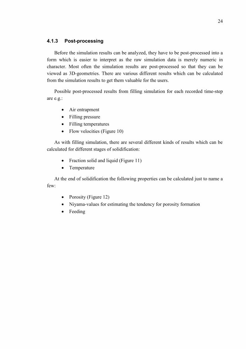
4.1.3 Post-processing
Before the simulation results can be analyzed, they have to be post-processed into aform which is easier to interpret as the raw simulation data is merely numeric incharacter. Most often the simulation results are post-processed so that they can beviewed as 3D-geometries. There are various different results which can be calculatedfrom the simulation results to get them valuable for the users.
Possible post-processed results from filling simulation for each recorded time-stepare e.g.:
Air entrapment Filling pressure Filling temperatures Flow velocities (Figure 10)
As with filling simulation, there are several different kinds of results which can becalculated for different stages of solidification:
Fraction solid and liquid (Figure 11) Temperature
At the end of solidification the following properties can be calculated just to name afew:
Porosity (Figure 12) Niyama-values for estimating the tendency for porosity formation Feeding

25
Figure 10 - Flow velocities in an iron casting during the mold filling stage.
Figure 11 - Fraction liquid-simulation results for a steel casting during the solidificationstage.
Figure 12- The porosity analysis of a large steel casting.
26
5 TEST MOLD DESIGN FOR EXPERIMENTALSTUDIES
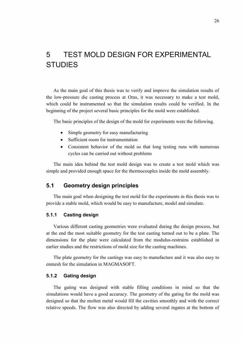
As the main goal of this thesis was to verify and improve the simulation results ofthe low-pressure die casting process at Oras, it was necessary to make a test mold,which could be instrumented so that the simulation results could be verified. In thebeginning of the project several basic principles for the mold were established.
The basic principles of the design of the mold for experiments were the following.
Simple geometry for easy manufacturing Sufficient room for instrumentation Consistent behavior of the mold so that long testing runs with numerous
cycles can be carried out without problems
The main idea behind the test mold design was to create a test mold which wassimple and provided enough space for the thermocouples inside the mold assembly.
5.1 Geometry design principles
The main goal when designing the test mold for the experiments in this thesis was toprovide a stable mold, which would be easy to manufacture, model and simulate.
5.1.1 Casting design
Various different casting geometries were evaluated during the design process, butat the end the most suitable geometry for the test casting turned out to be a plate. Thedimensions for the plate were calculated from the modulus-restrains established inearlier studies and the restrictions of mold size for the casting machines.
The plate geometry for the castings was easy to manufacture and it was also easy toenmesh for the simulation in MAGMASOFT.
5.1.2 Gating design
The gating was designed with stable filling conditions in mind so that thesimulations would have a good accuracy. The geometry of the gating for the mold wasdesigned so that the molten metal would fill the cavities smoothly and with the correctrelative speeds. The flow was also directed by adding several ingates at the bottom of

27
the casting. These ingates would help to direct the flow of the molten metal so that itwould be laminar when moving up in the cavity. The gating design also tried toeliminate the rapid changes in flow speed when the filling of the mold was at criticalstages. The resulting mold design can be seen in Figure 13.
Figure 13 – The design of the instrumented mold.
5.2 Instrumentation design principles
When designing the instrumentation of the mold it was decided that a total ofsixteen temperature measurement sites would be located in the mold, so that a sufficientamount of proper thermal data could be measured from the mold. The easiest way ofdoing this was to use two separate data loggers, both with 8 channels for thermocouples,one for each mold plate.
The mold was decided to be instrumented from the backsides of the mold plates.This was done by adding a in the back second cavity which could be sealed to the plateof the mold. The cavity would house the thermocouples and their wires used to measurethe temperatures at various different positions and depths within the mold plates.
As the loggers need to be protected from the heat and moisture, they were detachedfrom the mold plates and encased. The locations of the loggers were chosen to be closeto the mold, as this would enable to make the thermocouple wires as short as possible.As the loggers were attached to the mold construction, they would move with the moldat all of the different phases of the casting cycle, removing the eventual bending and

28
movements of the thermocouple wires. The locations of the logger enclosures can beseen in Figure 14.
Figure 14 – The concept of the test mold with instrumentation.
5.2.1 Thermocouple placement
The thermocouples were placed of various different places and depths in the mold.The main goal in placing the different sensors was to provide sufficient thermal datafrom different areas of the mold, such as the gating-system and the castings. A total of 8thermocouples were placed on each mold plate. Each plate had the same locations forthe thermocouples, but the depths of the thermocouples were different on each sideapart from one sensor which was identically placed on both sides.

29
6 IMPROVING THE ACCURACY OFSIMULATION RESULTS
There are several different parameters which influence the accuracy of castingsimulations. In order to improve the accuracy the correctness of these parameters has tobe verified so that they better represent the reality. Often the parameters and valuesprovided by the simulation software are only approximations or represent theparameters from a different material or process. In general the process parameters aredifferent in each foundry, and therefore it is vital to verify the parameters for eachprocess that is strived to be simulated.
There are several different categories of parameters and values which should beverified and which can be improved in most cases. It is easiest to divide the parametersand values into three separate groups, material data, HTC data and process data.
Material data
The material data can be verified and improved by either carrying out the requiredmeasurements or by getting the values through the use of theoretical models. While theactual measurements will usually provide better results, the difficulty of some of themeasurements may lead to the use of theoretical models instead of real measurements.The measurements involving the molten state materials can pose big challenges andproblems. For example, the viscosity and surface tension of the melt can be hard tomeasure as a function of temperature. Some of the potential measurement methods fordifferent material properties can be seen in Table 4.
Table 4 - Material properties and measuring methods.
Property Measuring methodDensity Dilatometry
Heat capacity Differential ScanningCalorimetry
Heat conductivity Laser flash diffusivityLiquidus and Solidus temperatures Thermal analysis
30
HTC values
The heat transfer coefficient values can be determined with a few different methods.Depending on the situation, the HTC-values can be calculated from measured datathrough mathematical methods which rely on theoretical models. The other way is totest different HTC-values in the simulation software and to compare the temperature-time curves of the simulation to the measured values. Through trial and error the correctHTC-values can be found with a sufficient number of iterations.
Depending on the instrumentation and thermal data, several different HTCs can bedetermined. In this thesis the HTCs for the casting-mold and mold-dipping mediainterfaces were established through running sequential simulations and by adjusting thevalues between each iteration cycle.
Process data
The process data for the simulation can be verified through the measurements of thedifferent parameters of the process. These include the filling pressure curves and thetiming of the different cycle phases.

31
EXPERIMENTAL STUDIES
The verification and improvements of the simulation results were accomplished byconducting several different experiments. Materials testing was carried out at TampereUniversity of Technology, Jönköping University and at the Oras Oyj. foundry inRauma.
7 STUDIES ON MATERIAL DATA
As stated earlier, it is vital to have the correct material data available in thesimulation software. As some of the materials used in the simulated process were notincluded in the database delivered with MAGMASOFT, the models for some of thematerials were only based on approximations and some were derived from the data forother similar materials.
Due to the lack of material data, it was crucial to update the database by describingthe materials missing from the database with the needed accuracy. The level of requiredaccuracy for the material data was determined by the impact of the material on theresults. The materials whose properties have the most impact on the casting process inlow-pressure die casting are the casting alloys and mold materials. Thus the highestdegree of accuracy was required for the casting alloys and the mold materialsthemselves.
7.1 Casting alloys
As the casting alloys and their properties have a profound influence on thesimulation results, it is crucial for them to have the correct material data for simulation.As the casting alloys and their properties need to be described in a broad temperaturerange, from room-temperature to well into the liquid-state, actual measurements for theproperties would have been both difficult and expensive to perform. This is why thecasting alloy data was improved through the use of theoretical models to simulate theneeded properties. These simulated properties were then verified through thermalanalysis of the alloys.

32
7.1.1 Theoretical models of copper alloys
The casting material properties were simulated by using the CAS-model (Copperalloy solidification model) developed at the Aalto University School of Engineeringduring the years 2002-2008. The CAS-model is based on the IDS-model (Interdendriticsolidification of steels) which has been developed since 1984. In comparison with theIDS-model, the CAS-model is much more complex due to the fact that the solidificationof copper alloys much more complex than the solidification of steels.
Figure 15 - Flow chart of the CAS-model showing the calculation modules of different phaseregion for multi-component copper alloys (L=liquid, F=FCC, B=BCC, C=Compound, G=Gamma,H=HCP). (Miettinen 2011)
The simulations for this thesis were carried by Jyrki Miettinen from CasimConsulting Oyj. As the CAS-model could not directly be used to simulate the materialsused in the simulated Oras process, it was modified by adding the missingthermodynamic data so that the simulations for the needed compositions could be run.

33
With the CAS-model the thermodynamic, diffusion, and dendrite arm spacing-datacan be calculated when the composition and cooling rate are known. Figure 15 showsthe flow chart of the CAS-model.
7.1.2 Verification of the simulated properties by thermal analysis
The verification of the theoretical model results for the casting alloys was carriedout with thermal analysis. The main goal of the thermal analysis was to verify theliquidus and solidus temperatures for both alloys. If the liquidus and solidustemperatures established through thermal analysis were reasonably close to thesimulated values, the simulated data could be considered as suitable for use.
The thermal analysis measurements were carried out for both casting alloys at Oras.The compositions of both alloys were analyzed before the measurements to ensure thatthe compositions were within the specifications.
The measurements were carried out with insulated measurement cups equipped withs-type thermocouples so that the cooling curves of the alloys could be measured. Twosuccessful measurements were accomplished on both alloys to ensure the reliability ofthe results.
The measurement equipment was set up next to the furnaces so that the metal couldeasily be poured into the measurement cups by using a hand ladle. After the metal hadbeen poured into the measurement cups, it was allowed to cool down sufficiently so thatthe phase transformations which were of interest could be seen on the cooling curves.The measuring setup can be seen in Figures 16 and 17.
The different phase transformations in the material can be seen as cooling-ratechanges in the thermal analysis. The phase transformation temperatures of interest in thecasting materials were the liquidus and solidus temperatures. As apparent in Figure 18,the material cools rapidly to the liquidus temperature, after which the cooling rate dropsand the temperature stabilizes. This is caused by the latent heat released by thesolidifying material. The cooling-rate increases again after the material is completelysolidified.

34
Figure 16 - The measurement setup forthe thermal analysis of the casting alloys.
Figure 17 - The instrumentation for thethermal analysis of the casting alloys.
Figure 18 - The thermal analysis of one of the casting alloys.
750
770
790
810
830
850
870
890
910
-2
-1.5
-1
-0.5
0
0.5
1
1.5
2
2.5
0 50 100 150 200 250 300 350 400 Tem
pera
ture
Ratio
of T
empe
ratu
re C
hang
e /
dC/s
Time (s)
SM2567 - Thermal Analysis of Solidification
dT/dt T/dt

35
7.2 Mold materials
The mold materials have a great influence on the solidification of castings andtherefore they were tested and the data was improved to enhance the simulationaccuracy. Two different mold materials were tested in order to establish what kind ofimpact they have in the casting process. The materials tested were the CuCrZr-alloyused at the Oras foundries and the more commonly used beryllium copper. Due to thelack of measuring equipment the measurements were conducted at JönköpingUniversity. The samples were sent pre-cut and finished according to specification toJönköping University where the actual measurements were performed by ToniBogdanoff.
Three different properties of the mold materials were measured so that thedescriptions for each material could be brought into MAGMASOFT. The thermaldiffusivity, density and specific heat of the materials were all measured as functions oftemperature. These values were also used in calculating the thermal conductivity of themold materials. The mold materials were tested for the temperature range from room-temperature to 600 °C as the mold materials should never experience temperatures over600 °C during their use.
7.2.1 Specific heat capacity
The specific heat capacity of the mold materials has a great influence on thesimulation results in the low-pressure die casting process. It determines how much themold will heat up during the casting cycles and how much heat it can withdraw from thecastings.
Figure 19 - The setup used to measure the specific heat capacity of the samples. (Bogdanoff2011)

36
The specific heat capacity of the mold materials was measured at JönköpingUniversity with their differential scanning calorimetry equipment (Figure 19).
7.2.2 Density
Density of the mold materials is also of interest when describing the materials foruse in casting simulation programs. The density is also used to calculate other propertiesof the materials such as, e.g., the thermal conductivity.
The density of the mold materials was measured through the use of a dilatometer atJönköping University (Figure 20). The dilatometer was used to measure the linearthermal elongation of the samples with increasing temperature. This data could then beused to calculate the density of the samples as a function of temperature, when theinitial length and weight of the samples were known.
Figure 20 - The dilatometer used to measure the thermal elongation of the samples. (Bogdanoff2011)
7.2.3 Thermal diffusivity
The thermal diffusivity of the samples was measured with a laser flash diffusivityequipment. The thermal diffusivity was measured to get the thermal conductivity valueswithin the wanted temperature-range for both of the mold materials. These values wereneeded to describe the mold materials in the simulation software.

37
Figure 21 - The basic structure of laser flash diffusivity equipment. (Netzsch n.d.)
Figure 22 - Working principle in the measurement of the thermal diffusivity with laser flashdiffusivity equipment. (Lenseis n.d.)
In laser flash diffusivity measurements the samples are subjected to precise laserpulses (Figures 21 and 22) and the temperature of the backside of the samples ismeasured with an IR sensor which can detect how much heat is transferred to the otherside of the sample. When monitored continuously the thermal diffusivity can becalculated from the temperature change as a function of time. (Lenseis n.d.)

38
7.3 Core materials
The core materials were only compared with each other so that the differencesbetween the different materials could be determined. As the core materials transfer onlyvery small amounts of heat away from the casting when compared to the metallic moldmaterials, their influence on the results is so small that accurate models of the coresands are not as crucial as those of the mold materials.
7.3.1 Comparative testing of the thermal conductivity in sand materials
The different core materials were tested so that the differences between their thermalconductivities could be seen. No actual conductivity values were obtained during themeasurements. These measurements were carried out in order to establish the eventualneed for more accurate measurements on the core materials.
The comparative testing on the core materials was carried out on small sample coreswhich had been made at Oras. A total of five different compositions of cores were testedto establish whether there are any significant differences between the core materials.
7.3.2 The setup of experiments
The measuring equipment consisted of a hot-plate, a large copper plate which wasused to eliminate the uneven heat distribution, two thermocouples, a data logger and alaptop computer (Figures 23, 24 and 25). In addition a few pieces of kaowool were usedto insulate the surroundings of the samples while measuring.
The two thermocouples were used to measure both sides of the sample. Thethermocouple on the bottom of the sample was used to ensure that the hot-plateprovided a stable temperature. The second thermocouple was used to measure thetemperature on top of the samples. The rate at which the temperature increases on top ofthe sample depends on the thermal conductivity of the samples.
Figure 23 - The measurement setup for the thermal conductivity studies of the core sands.
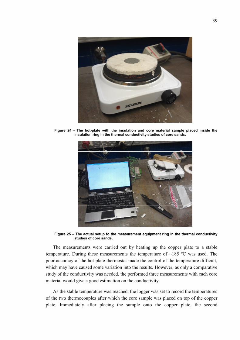
39
Figure 24 - The hot-plate with the insulation and core material sample placed inside theinsulation ring in the thermal conductivity studies of core sands.
Figure 25 – The actual setup fo the measurement equipment ring in the thermal conductivitystudies of core sands.
The measurements were carried out by heating up the copper plate to a stabletemperature. During these measurements the temperature of ~185 ºC was used. Thepoor accuracy of the hot plate thermostat made the control of the temperature difficult,which may have caused some variation into the results. However, as only a comparativestudy of the conductivity was needed, the performed three measurements with each corematerial would give a good estimation on the conductivity.
As the stable temperature was reached, the logger was set to record the temperaturesof the two thermocouples after which the core sample was placed on top of the copperplate. Immediately after placing the sample onto the copper plate, the second

40
thermocouple was placed on top of the sample. Kaowool insulation was placed on topof the sample and thermocouple as quickly as possible. This insulation was placed therein a way which enabled the pressing of the thermocouple against the measuring surfacefor better contact and the exclusion of any external factors eventually influencing themeasurement. The measurements were run as long as necessary for the samples to heatup close to the hot plate temperature.
7.3.3 Results
The measurement results were evaluated with two different criteria for each corematerial. An average heating rate for each material was calculated and the temperature-vs.-time-curves measured on the top surface of the samples for each material werecompared.
Figure 26 shows the average heating rates for all of the different core materials. Asis evident from the results, there are no significant differences between the thermalconductivities of the core materials. The differences are so small that they will have nosignificant effect on the heat transfer during the casting cycle. Figure 27 further suggeststhat there are no significant differences between the measured core materials in thesetests.
A comparative measurement with a sample of the mold-material would have beenvery good in showing how low the thermal conductivity really is in the sand materials.Unfortunately a sample of the mold material could not be obtained in time for thetesting.
While the measurements on the core materials do not reveal any differences in thethermal conductivities of the core materials, it is possible that at higher temperatures thedifferences are bigger. The temperatures during the casting process can rise up to 1000ºC and of those temperatures the properties of the core materials can behave completelydifferently as there are many reactions which can have big influence on the castingresults. The binders within the core materials will burn, releasing varying amounts ofgases into the mold cavities and into the melt.
While the thermal conductivities of the sand materials don’t have any significantdifferences, cores from different sands have proven to have significant differences inpractice. One of the possible explanations for this is the fact that the different bindersystems react differently at higher temperatures, giving off different amounts of gases.As the pressure of the gases given out from the cores at high temperatures can have bigeffect on the feeding of the casting, the core materials can have a big impact on wherethe feeding problems may arise.

41
Fortunately newer versions of MAGMASOFT will include better simulationpossibilities for the behavior of sand and core materials. The gases released by the coreswill be taken into account in the newer versions, which will have an improving effect onthe accuracy of simulations especially in this process. With the current version ofMAGMASOFT it is not possible to simulate the behavior of the core materials with thisaccuracy.

42
Figure 26 - The core material heating rate as measured at the top surface of the core sample in thecomparative thermal conductivity measurements of core sands.
Figure 27 - The temperature vs. time measurements taken from the top surfaces of the coresamples in the comparative thermal conductivity measurements of core sands.
0.00
0.10
0.20
0.30
0.40
0.50
0.60
100 150 200 250 300 350 400 450
Heat
ing
Rate
/ºC/s
Time /s
Core Material Heating Rate Comparison
Sand 1 Average
Sand 2 Average
Sand 3 Average
Core 4 Average
Sand 5 Average
-20.00
0.00
20.00
40.00
60.00
80.00
100.00
120.00
140.00
160.00
180.00
50 100 150 200 250
Tem
p,er
atur
e (ºC)
Time (s)
Temperature At The Top Of The Sample
Sand 1 Average
Sand 2 Average
Sand 3 Average
Sand 4 Average
Sand 5 Average

43
8 CASTING EXPERIMENTS
The casting experiments were carried out at Oras Foundry on the two studied alloysusing two different casting machines. The mold was also manufactured andinstrumented at Oras tool shop.
8.1 Manufacture of the test mold
8.1.1 Machining the mold
The test mold was machined from wrought billets of the mold material. The moldmaterial used for the mold was the standard material used at the foundry, CuCrZr. Themold plates were machined in two different stages, as both sides of the mold had to bemachined. The cavities for the castings and the gating system were machined onto thefront sides of the mold plates and the cavities for the instrumentation were machined onthe backsides. Figures 28 and 29 show the molds in different stages of manufacturing.
8.1.2 Instrumentation of the mold
The instrumentation of the mold was carried out by using K-type thermocouples.The thermocouples used in this project were produced with thin tips in order to improvethe sensitivity of the thermocouples to the changes in temperature.
The thermocouples were placed in drilled holes which provided the correctmeasuring points. The thermocouples were secured mechanically to the mold in order toprevent their movement during testing and to ensure the proper contact to the mold at alltimes. A thermal compound was used in one of the mold plates in order to establish theinfluence of a silicon-based thermal compound on the results. Figure 30 shows thethermocouples installed into the mold plate.
The wires of the thermocouples were secured within the instrumentation cavity ofthe mold so that manipulating the wires outside the mold would not break or movethem. The instrumentation cavity of the mold was covered with a steel cover which hada hole, allowing the thermocouple wires to pass through. The cover plate was sealed sothat no moisture could enter the cavity during the use and influence the results.

44
Figure 28 - The back side of the test mold plate with the instrumentation cavity.
Figure 29 - The sample cavities of the instrumented test molds.
Figure 30 - Instrumentation of the mold Figure 31 - Protection of the thermocouplewires in the test mold.

45
The thermocouple wires were routed to the data logger enclosure, which was locatedbehind the mold. Even if the thermocouple wires were rated for high-temperature use,they were further shielded with a heat resistant braided sleeve (Figure 31). This sleevingalso made it easier to organize the wires.
The logger enclosure had two openings through which the necessary cables couldpass. The thermocouple wires were brought into the enclosure through a hole at theback of the enclosure (Figure 32). The necessary power- and USB-cables for the datalogger were brought into the enclosure through a smaller hole on the side of theenclosure.
Figure 32 - Wiring of the thermocouples to the data logger enclosure for the castingexperiments.
Enclosures for the data loggers were necessary due to the high temperatures andlevels of humidity in the casting environment. The data logger enclosures weremachined from aluminum and they were sealed from the environment with O-ringgaskets. As aluminum conducts heat very well, it was also necessary to shield thealuminum enclosure from the heat with additional insulation.

46
8.1.3 Mold setup
Figure 33 - The protection of theinstrumentation and wiring of the moldswhen attached to the casting machine for thecasting experiments.
Figure 34 - The computer setup used torecord the measurements.
The data loggers were attached onto fixtures on the mold assembly. These fixtureswere also used as heat shields for the wiring. The fixture was designed so that a part ofit would guide the heat from the furnace away from the wires during casting.
The data loggers were connected to a laptop which was used to record the data(Figure 34). The data loggers could also have been installed to work off-line as well, buthaving the real time measurements visible during testing helped in determining whetherthe process was stable enough for the measurements.
The wiring of the data loggers was routed through the casting machine so that thewires would not interfere with the motions of the casting machine (Figure 33). Thelength of the wires posed some difficulties while routing, as the casting machines makequite large movements during the casting cycles.
8.2 The casting experiments
The goal of the casting experiments was to provide adequate amount of thermal datawhich could then be compared with the data produced via simulation. The goal was tocast sufficiently long series for the measurements to stabilize. The measurements wererepeated with both casting alloys and for both coating systems.

47
The process parameters were established when the test mold was first used with theinstrumentation. This way the stability of the process could be confirmed with thechosen parameters. When the parameters were established, the same values were used inall consequent tests with some small adjustments when casting with the second castingmachine.
Some of the differences in process parameters for the two casting machines werealso caused by the operator. Therefore the results between the different machines are notdirectly comparable. This only causes the need to calibrate the simulations for eachcasting alloy separately.
The measurements were carried out so that at least ten successfull cycles were castin succession so that the process would have sufficient time to stabilize. Allmeasurements besides the initial testing were carried out during two working shifts atthe foundry. Some of the test castings can be seen in Figure 35. Figure 36 shows someof the measured thermal data from the casting experiments. The figure shows a total ofeight different channels of temperature data over time. A total of 12 cycles were run insuccession for these measurements.
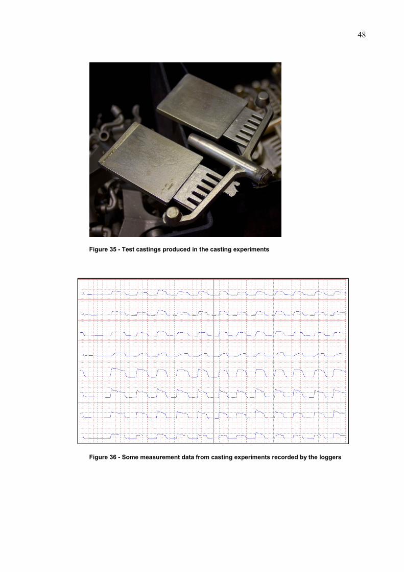
48
Figure 35 - Test castings produced in the casting experiments
Figure 36 - Some measurement data from casting experiments recorded by the loggers

49
9 RESULTS OF IMPROVED MATERIAL DATAAND PROCESS PARAMETERS
9.1 Improved material data and process parameters
During the course of this project, most of the vital material data and processparameters were updated for the simulations. As the accuracy of the material data andprocess parameters was improved the simulation results have also improvedsignificantly.
9.1.1 Casting alloys
While earlier there was only one casting alloy material described in the software forthe Oras simulations, two new materials were described in order to improve thesimulation results for both alloys. One of these new materials was the low lead alloy andthe other was a more accurate material for the lead-containing alloy.
As was apparent after the simulated properties and the thermal analysis of bothalloys, there was a significant difference to the originally used material model in bothcases. The simulated properties and thermal analysis of the low-lead alloy provided newinsight into many of the issues, which are only existent with this new alloy. Whileearlier it was believed that both used alloys should perform similarly and have similarproperties, it was proven that the low-lead alloy had higher melting temperatures whencompared to the normally used lead containing yellow brass.
9.1.2 Mold materials
Originally the simulations were run with only approximated material data of themold material. After the project two new mold materials have been described into thesoftware database, the currently used alloy and a beryllium copper alternative. Thereason for describing both materials into the software database is to reveal whether theunusual mold material used by Oras is contributing to some casting faults and problems.
9.1.3 Core materials
As the project was carried out before a new version of MAGMASOFT was released,it was decided that describing the core materials was not as important as the descriptionof the other system materials. The main reason for this is the addition of large amounts

50
of new research-verified material data on different core and mold materials to the newcoming version of the software. Therefore only a comparative test was carried out sothat the differences between the different core materials could be determined. Ifsignificant differences between the materials would have been revealed, the importanceof modeling the core materials into the software database would have been re-evaluated.Within a few years MAGMASOFT will provide better simulation of core materials intothe software. With the new software version it would be wise to reconsider the need ofimproving the core material data.
9.1.4 Heat transfer coefficients
Heat transfer coefficients were in the core of research in this project as they have thestrongest influence on low-pressure die casting simulation results. The HTCs wereimproved by running the simulations with different HTC-profiles and by improving theaccuracy over several iterations of the coefficients.
This phase of the project demanded high computational power, which was availablewith a workstation provided by MAGMASOFT. A total of 38 iterations were run inorder to improve the accuracy of the HTC-values.
Figure 37 - Comparison of the measured temperature-time profile data with the new (V24) andold (V0) simulated profile
Tem
pera
ture
/ C
°
Time / s
Measured Data vs. Simulated Data
Measurements V0 V24
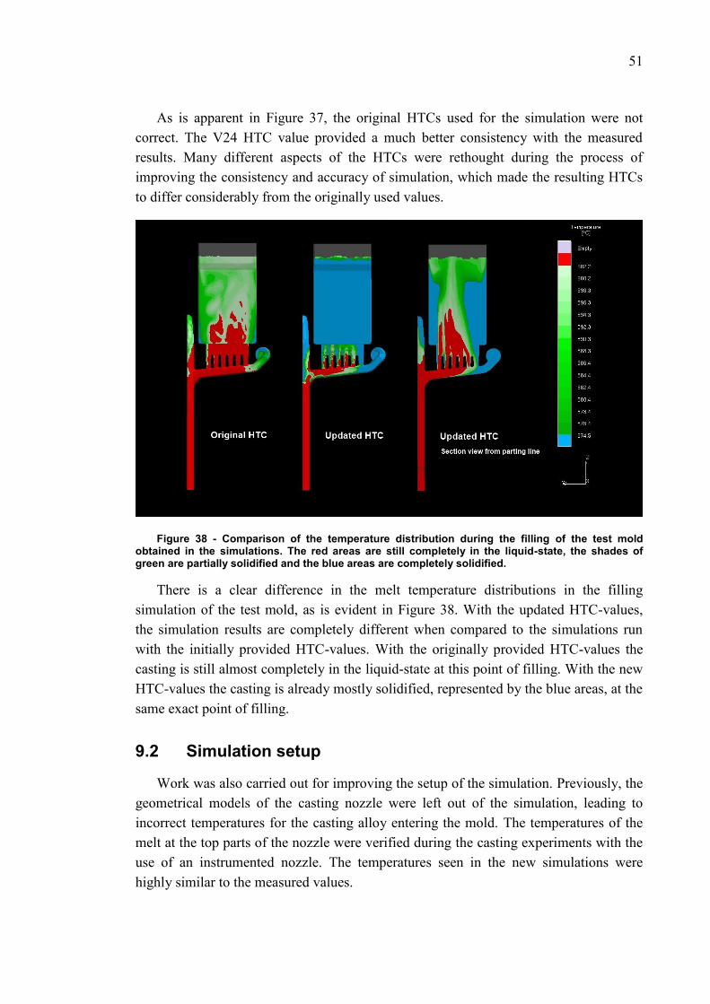
51
As is apparent in Figure 37, the original HTCs used for the simulation were notcorrect. The V24 HTC value provided a much better consistency with the measuredresults. Many different aspects of the HTCs were rethought during the process ofimproving the consistency and accuracy of simulation, which made the resulting HTCsto differ considerably from the originally used values.
Figure 38 - Comparison of the temperature distribution during the filling of the test moldobtained in the simulations. The red areas are still completely in the liquid-state, the shades ofgreen are partially solidified and the blue areas are completely solidified.
There is a clear difference in the melt temperature distributions in the fillingsimulation of the test mold, as is evident in Figure 38. With the updated HTC-values,the simulation results are completely different when compared to the simulations runwith the initially provided HTC-values. With the originally provided HTC-values thecasting is still almost completely in the liquid-state at this point of filling. With the newHTC-values the casting is already mostly solidified, represented by the blue areas, at thesame exact point of filling.
9.2 Simulation setup
Work was also carried out for improving the setup of the simulation. Previously, thegeometrical models of the casting nozzle were left out of the simulation, leading toincorrect temperatures for the casting alloy entering the mold. The temperatures of themelt at the top parts of the nozzle were verified during the casting experiments with theuse of an instrumented nozzle. The temperatures seen in the new simulations werehighly similar to the measured values.

52
While the addition of the nozzle to the simulations increased the accuracy of thesimulations by some degree, it also increased the number of cells which have to besimulated and prolonged the simulation time.
9.3 Further verification of the simulation results
In this work the simulation results have been verified by comparing the simulatedresults to the temperature-time profiles measured with the instrumented mold. Thesimulation results were also verified by simulating other production castings and theirmolds by comparing those simulation results to the produced castings.
A couple of production stage castings were selected to verify the simulation results.Both castings were challenging in their own way, which made them interesting cases tosimulate.
When simulated with the original dataset provided with the software, the simulationresults represented the reality only poorly. The simulations with the original datasetcompletely failed to reveal the common problems related to these castings. Mostly thiswas due to the wrong HTC-values.
When using the simulation software with the improved dataset, the simulationresults represented the reality much better. Currently it seems that many of the earlierunexplained problems related to these castings can be explained through the use of thesimulation results obtained with the new dataset.

53
10 CONCLUSIONS
The present project has both verified and improved the simulation results for thelow-pressure die casting process at Oras Oyj. The improvement of the data used forsimulation has had significant effects on the simulation results. Due to this improvementin accuracy, casting simulation can be used as a better tool guiding the design ofcastings and tooling than before the project. Earlier the simulations could only be usedto identify possible locations for feeding problems, but with the new data the fillingbehavior and the solidification of the castings can be evaluated with high accuracy.
With the use of simulation and tool development a better level of process know-howcan be achieved and product designs can be better optimized for casting. This ispossible due to the added knowledge of the casting process and having a tool which canbe used to easily test changes in design and process parameters.
Simulation can also be used in the development of the casting process, as theinfluence of the different process parameters can be determined. With this informationthe process can be optimized.
10.1 Future areas of research
While most data acquired during this project are universal for all castings producedwith the studied materials, some of the process parameters, such as cycle timings andHTCs, are not the same for all castings.
10.1.1 Improvements to simulation accuracy
The casting simulation accuracy can further be improved by fine-tuning thesimulation parameters and data over time by comparing the simulation results to theresults obtained with real castings. As this project only used a few different geometriesto improve and verify the data used for simulations, it is apparent that the data can befurther improved by using more references.
The instrumentation of other well-known molds would provide valuable data for thefurther tuning of the simulation software, as currently the only useful thermal data fromthe molds have been measured during this project with one mold. When more thermaldata from different molds exist, this data can be used to improve the HTC-curves forsimulation. This would further improve the simulation results.

54
When new materials are introduced to the process, they should also be describedinto the software in the same way as the new materials were described during thisproject. This includes the possible new casting alloys as well as new mold and corematerials.
10.1.2 Improvements for process control and management
The instrumented production molds could also be used for the process control andfor the management of the casting processes. The actual casting times can easily be seenand checked from the thermal data measured from the molds and the actual moldtemperatures can be seen more reliably. The mold temperature data could be used tocontrol the dipping time of the mold so that a stable casting temperature for the moldcould be sustained through the whole casting process.
In the future it may also be possible to use the thermal data measured from themolds to fine-tune the filling pressure vs. time curves of the casting machines. It wouldbe fairly easy to see how the molds are filled and this data could be used to adjust thecurves for better filling behavior.

55
11 REFERENCES
Administration, Occupational Safety & Health. Beryllium. United States Department ofLabor. 11 November 2006. http://www.osha.gov/SLTC/beryllium/index.html(accessed October 20, 2011).
Bader, Michael. Die Design. Document. KWC Engineering. Unterkulm, 5726, 11 July2002.
Bogdanoff, Toni. Pictures from the laboratory. Jönköping University, Jönköping.
Campbell, John. Castings (Second Edition). 2. Oxford: Butterworth-Heinemann, 2003.
Harkness, J. C., W. D. Spiegelberg, and W. R. Cribb. “Beryllium-Copper and OtherBeryllium Containing Alloys.” In Properties and Selection: Nonferrous Alloysand Special-Purpose Materials, Volume 2, ASM Handbook, 403-427. Ohio:ASM International, 1990.
Hinkkanen, Mikko. “Rengasmuottisegmenttien valumenetelmän kehittäminen.” MScThesis, Tampere, 2009.
Key To Metals AG. Copper-Zinc Alloys: The Brasses. Key to Metals. 2010.http://www.keytometals.com/Article69.htm (accessed July 2011).
Kondracki, M., and J. Szajnar. “Special non-leaded brasses for permanent mouldcasting.” Journal of achievements in materials and manufacturing engineering(International OCSCO World Press) 25, no. 2 (December 2007).
La Fontaine, A., and V.J. Keast. “Compositional distributions in classical and lead-freebrasses.” Materials Characterization 57 (2006): 424-429.
Lenseis. LFA 1000 Laser Flash Apparatus. n.d.http://www.linseis.net/html_en/thermal/laserflash/lfa_1000.php (accessedAugust 2011).
Mampaey, F. “Practical Examples Using the Finite Volume Method for Simulating theCasting Process.” AFS Transactions 01-075 (American Foundry Society), 2001:1 of 10.

56
MatWeb. How Alloying Elements Affect the Properties of Copper Alloys. MatWeb. n.d.http://www.matweb.com/reference/copper-alloys.aspx (accessed February2011).
Metaal, Brouwer. “Brouwer Metaal - Copper Alloys : Materials/Applications.” n.d.http://www.brouwermetaal.com/?page=materials&applications=materials%20copper%20alloys (accessed February 2011).
Miettinen, Jyrki. Neljän kuparimessinkiseoksen jähmettymismallinnus. Espoo: CasimConsulting Oy, 2011.
Netzsch. Analyzing & Testing - LFA 457 Micro Flash. NETZSCH-Gerätebau Gmbh.Seib, n.d.
Polyteknisk Forlag. Fundamental of Numerical Modelling of Casting Processes. 1st.Edited by Jesper Hattel. Lyngby: Polyteknisk Forlag, 2005.
Sadayappan, K., M. Sahoo, and H. T. Michels. “Copper and Copper Alloy Castings.” InCasting, Volume 15, ASM Handbook, 1085-1094. Ohio: ASM International,2008.
The University of Michigan; Missisippi State University. “Investigation of HeatTransfer at the Mold/Metal Interface in Permanent Mold Casting of LightAlloys.” Final Technical Report, The University of Michigan, Ann Arbor, 2005.
Woycik, Gregory G, and Gordon Peters. “Low-Pressure Metal Casting, Casting,Volume 15.” In ASM Handbook, by ASM International Handbook Committee,edited by ASM International, 700-708. Ohio: ASM International, 2008.