Embed Size (px)
Citation preview

University of Warwick institutional repository: http://go.warwick.ac.uk/wrap
This paper is made available online in accordance with publisher policies. Please scroll down to view the document itself. Please refer to the repository record for this item and our policy information available from the repository home page for further information.
To see the final version of this paper please visit the publisher’s website. Access to the published version may require a subscription.
Author(s): J. Toby Mottram and Behrouz Zafari
Article Title: Pin-bearing strengths for bolted connections in fibre-reinforced polymer structures Year of publication: 2011
Link to published article: http://dx.doi.org/10.1680/stbu.2011.164.5.291 Publisher statement: None

1
J. T. Mottram and B. Zafari, ‘Pin-bearing strengths for design of bolted connections in pultruded structures,’ Structures and Buildings, 164 5, (2011), 291–305. ISSN 0965-0911 Paper: Ms. No. SB-D-10-00013R1 doi: 10.1680/stbu.2011.164.5.291
Pin-bearing Strengths for Bolted Connections in FRP Structures
J. T. Mottram BSc PhD DSc CEng FIStructE
Reader, University of Warwick
B. Zafari BSc MSc
PhD student, University of Warwick
Original: 31 January 2010 Revised: 21 January 2011
Principal Author (Contact details):
Dr J. Toby Mottram
Civil Research Group
School of Engineering
University of Warwick
CV4 7AL
Tel: 024 765 22528 email: [email protected]

2
Summary
Presented in this paper are pin-bearing strengths for pultruded fibre reinforced
polymer materials that are required to check for the bearing resistance when designing
bolted connections. For steel pin diameters up to 16 mm equivalent test results, at
room temperature, using the European standard test method BS EN 13706-2 and a test
method (like ASTM D 5764) are shown not to be significantly different. Because the
latter method uses much smaller specimen blanks new pin-bearing strengths can be
determined for the web material in a 203 x 203 x 9.5 Wide Flange shape, with the
connection force at 0o, 45o or 90o to the direction of pultrusion. An evaluation is made
of the test results and recommendations given on how pin-bearing strengths are to be
determined so that they will match the geometries of bolted connections and
connection forces found in practice.
Keywords: Codes of practice & standards, FRP composite structures, Strength and
testing of material.
Notation
d Bolt diameter, mm
dn Hole diameter, mm
e1 End distance, mm
e2 Side distance, mm
t Constant thickness of FRP material, mm
w Constant plate width for single bolted connection with e2 = w/2, mm
brF Pin-bearing strength for the orientation of the resultant force at the
bolt/FRP contact with respect to the direction of pultrusion, MPa
br0F Pin-bearing strength in the longitudinal (0o) direction of pultrusion, MPa
br45F Pin-bearing strength for 45o to the direction of pultrusion, MPa

3
br90F Pin-bearing strength in the transverse (90o) direction of pultrusion, MPa
Rbr Pin-bearing strength (resistance) per bolt, kN
Rbr,test Compressive force using the Warwick University test arrangement, kN
Rn Nominal (design) strength (resistance) for bolted connection, kN
Introduction
In 2007 the American Society of Civil Engineers (ASCE) and the American
Composites Manufacturers Association (ACMA) signed a three-year agreement to
develop a pre-standard for the Load and Resistance Factor Design (LRFD) of
Pultruded Fiber-Reinforced Polymer (FRP) Structures. When published this LRFD
standard is expected to help structural engineers and architects use pultruded FRP
composites (standard shapes) in building and transportation designs and bring
benefits, such as its strength-to-weight ratio, resistance to corrosion, low maintenance
and long life cycle, to US infrastructure (Anonymous, 2007).
Pultruded standard shapes consist of a number of thin-walled panels of glass fibre
reinforced polymer matrix connected to form open or closed cross-sections. I, Wide
Flange (i.e., an H cross-section), channel, leg-angle shapes (or profiles) mimic steel
sections, and so it is natural that construction follows what is seen in conventional
steelwork (Turvey, 2000; Bank, 2006; Anonymous 2011a,b). Being lightweight and
resistant to corrosion pultruded shapes and structures are increasingly used where
these attributes meet the clients’ requirements.
Standard shapes (Turvey, 2000; Bank, 2006; Anonymous, 2011a,b) are reinforced
with E-glass fibres and possess a matrix often based on a polyester or vinyl ester
thermoset resin with fillers and additives. Each panel has an outermost layer of a thin

4
protective veil, which does not provide reinforcement. The first reinforcement layer is
often of Continuous Filament (or Strand) Mat (abbreviation CFM (or CSM)). This is
followed by alternate layers of unidirectional (UD) rovings and CFM forming the
material’s core. Because each profile has its own layered construction the directional
elastic constants and material strengths of the orthotropic fibre reinforced material
will change accordingly (Bank, 2006; Anonymous, 2011a,b), and this poses a
challenge when mean or characteristic properties are required for the preparation and
application of design formulae in the LRFD pre-standard (Anonymous, 2011c).
The main class of construction that will be designed by the LRFD pre-standard is for
non-sway braced frames that have simple shear joints between main members and
bracing to transfer lateral loads to the ground. A simple joint can be assumed not to
transmit bending moments. The method of connection is by steel bolting (there is no
adhesive bonding), and so the types of connections scoped will correspond to the
engineering drawings in in-house design manuals (see, e.g. Figure 1), independently
prepared by American pultruders (Anonymous, 2011a,b). Bank (2006) and Turvey
(2000) show applications of such bolted connections in frame structures of pultruded
shapes. Chapter 8 in the pre-standard (Anonymous, 2011c) is therefore for the design
of such bolted connections, and the first author was a member of the drafting team.
To scope the types of connections and joints the bolted connection chapter combines
the need to design for frame joints, such as the web-cleated type shown in Figure 1
(will classify as simple), with the design of plate-to-plate connections, such as there is
for the beam’s web and in each of the two legs for the web cleat shown in the figure.
The beam shape in Figure 1 can be used to define the orientations of the material with

5
the 0o (or longitudinal) direction coincident with the direction of pultrusion of the
beam. The 90o (or transverse) direction is normal to the pultrusion direction, within
the plane of the panels forming the thin-walled shape. An orientation of 45o is for the
angle half way between the 0o to 90o directions. For a pultruded web-cleat in Figure 1
the orientations for the 0o and 90o directions will be rotated through ninety degrees
relative to their directions in the beam shape.
In this paper, we shall consider the connection building block for joints, which
comprises bolting and two or more thicknesses of material. We shall restrict the
discussion to plate-to-plate connections having the double lap-shear configuration,
and with in-plane loading. It is well-known that such bolted connections of pultruded
material fail ultimately in one of a number of failure modes (e.g. bearing, shear-out,
cleavage, net-tension and block shear). In design, the size of the steel bolting is
chosen such that failure, either by bolt rupture or bolt pull-through, should not occur
(Mottram and Turvey, 2003). The sketches in Figure 2 show the simplified stress
distributions and fracture paths for these distinct plate-to-plate modes of failure (for
tension loading). Mix modes (e.g. when the connection force is off-axis with respect
to the direction of pultrusion) are possible and block-shear is a mode when there are
multiple rows of bolts (Mottram and Turvey, 2003).
For the basic connection building block of a single-bolted situation the plate is of
constant thickness t and constant width w, which is twice the edge (or side) distance e2
because the bolt is centrally placed. Other relevant geometric parameters are the hole
diameter dn, and the bolt diameter d, which due to a hole clearance is less than dn.
Mottram and Turvey (2003) used the results from series of tests to observe that the

6
mode of failure will change on varying the geometric ratios e1/d (or e1/dn) and w/d (or
w/dn), with w = 2e2. To promote failure of the single bolted connection in the bearing
mode these two geometric ratios need to be four or higher when the FRP material is
pultruded.
Bearing (mode in Figure 2(a)) is the only one of the ‘distinct’ modes that does not
always give a brittle failure response, and can be used to provide the bolted
connection with a degree of damage tolerance; this is desirable in design because it
imparts structural integrity into the design (Mottram and Turvey, 2003; Thoppul et
al., 2009). It is also the mode of failure with a strength formula (Bank, 2006) that
requires its ‘own’ material strength property ( brF ), and the formula per bolt is
brbr FdtR . (1)
Using LRFD standard language the pin-bearing strength (Rbr) by Equation (1) is given
by the projected area of bolt bearing multiplied by the characteristic pin-bearing
strength ( brF ) for the orientation () of the resultant force at the bolt/FRP contact
with respect to the direction of pultrusion. When designing a bolted connection, such
as shown in Figure 1, bearing strength (in kN) is to be the sum of the appropriate Rbrs
calculated using Equation (1) multiplied by the number of bolts for each of the
different pin-bearing strengths per bolt. Clearly, if the bolt and hole sizes are constant
then only a single Rbr is to be calculated.
When the connection force is aligned with the longitudinal direction of pultrusion we
have = 0o, and br0F is the highest pin-bearing strength. If = 90o the force is
coincident with the transverse direction and br90F is the lowest pin-bearing strength. In

7
the pultruders’ manuals (Anonymous, 2011a,b) the 0o direction is referred to as
LengthWise (LW) and the 90o direction as CrossWise (CW). For the web connection
in Figure 1 the nominal pin-bearing strength (resistance) is 2Rbr, with the terms in
Equation (1) to be brF = br
90F , t = 9.53 mm (3/8 in.) and d = 9.53 mm (3/8 in.), or 12.7
(1/2 in.) or 15.85 mm (5/8 in.).
By definition the pin-bearing strength ( brF ) is the mean stress over the bearing area at
bearing failure (however the failure load is defined, and there are several choices
(Johnson and Matthews, 1979), as shown in Figure 3), when there is no lateral
restraint. It is further assumed that when measuring brF there is no bolt thread bearing
against the FRP material. It is important to emphasize that for the bearing strength to
be the pin value there must be no tightening of the bolting. It is well-known that
bearing strength increases significantly on tightening, because a torqued steel bolt
provides stiffness to oppose the ‘free’ through-thickness deformation (Cooper and
Turvey, 1995; Mottram, 2004). Other factors not already mentioned that influence the
bearing strength are; the fibre reinforcement architecture, material thickness and
orientation, the bolt-flexibility, the presence of thread in contact with the bearing
surface, the bolt diameter-to-thickness (d/t) ratio, the size of the clearance hole and
environmental conditioning.
The strength equations for the other distinct failure modes shown in Figure 2 require
one or two material strengths (such as those tabulated in Anonymous (2011a) and
Anonymous (2011b)), and appropriate values may be determined by using, for
example, an ASTM standard test method.

8
Historical Review of Test Methods for Pin-bearing Strength
A historical review of standard test methods will be used to show that there is a lack
of consistency in how pin-bearing strengths of pultruded materials have been
measured. Prior to giving the review, it is appropriate first to summarise the likely
scope of bolted connections by way of the LRFD pre-standard chapter. Material
thicknesses are to be in the range from 6.35 mm (1/4 in.) up to, and, perhaps,
including 25.4 mm (1 in.). Standard pultruded shapes (Bank, 2006, Anonymous,
2011a,b) are to be either of flat sheets or structural cross-sections (I, H, leg-angles,
etc.); with the structural shapes having the higher volume fraction of UD rovings.
This unidirectional E-glass reinforcement is aligned with the longitudinal (0o or LW)
direction. Although not completely excluded in practice, it will be assumed in this
presentation that there is no or little of the bolt thread in bearing. Bolts and nuts will
be to ASTM standards A193, A304, A307 and A316 and the range of bolt diameters,
d, is from 9.53 mm (3/8 in.) up to, and including 25.4 mm (1 in.). Hardened flat
circular washers are to have an outer diameter at least twice the nominal bolt
diameter, and at least one washer is to be used at the head of the bolt and at the nut.
Bolts are to be torqued to the snug-tightened condition. Guidance for setting this bolt
tensioning is not specified in the LRFD pre-standard. The nominal hole diameter, dn,
is to be a minimum of 1.6 mm (1/16 in.) larger than the nominal bolt diameter, d, and
holes are to be drilled or reamed. The hole clearance is therefore in the range 0.06dn to
0.14dn as the bolt diameter reduces from 25.4 to 9.53 mm.
With such a wide scope in connection details permitted by the pre-standard chapter
we need confidence in published pin-bearing strengths to be used with Equation (1).
So why did the writers of Chapter 8 (Bolted connections) specify a pin-bearing

9
strength in Equation (1) when the LRFD pre-standard specifies that the bolting is to
be snug-fit? The beneficial effect of bolt tightening on bearing strength (Cooper and
Turvey, 1995) has to be off-set by its long-term reduction due to creep relaxation
(Thoppul et al., 2009; Mottram, 2004) and from other possible influences to durability
over the intended service life of pultruded structures, which will be in tens of years.
To ensure that a bolted connection should not fail prematurely it was deemed prudent
by the pre-standard writers for the bearing strength per bolt to be calculated using
Equation (1) with the ‘lowest’ characteristic strength that can exist in practice, and
this is the pin-bearing strength that accounts for all detrimental affects.
Although historical bearing strengths are reported (Wang, 2004; Lutz, 2005,
Anonymous, 2011a,b) their provenance is not always in the public domain and
significant differences in values may be partially explained by differences in materials
and test methods. Another reason for observed differences is the seven possible ways
of defining failure load from the load-stroke plot, which can be recorded during the
bearing strength test. Figure 3 shows a typical bearing load against measured
extension (stroke) plot based on 1970s research by Johnson and Matthews (1979).
Consideration of this curve suggests that there are seven ways of defining failure load,
and these are:
(a) The maximum load. Usually considerable damage may have occurred in
reaching this load.
(b) The first peak in the load/extension plot. Damage sustained up to this load is
not insignificant.

10
(c) The load corresponding to a specified amount of hole elongation; which has
been specified at various percentages up to 4% (ASTM D 953-02, 2002;
MIL-HDBK-17-3F, 2002; ASTM D5961-05, 2005; Thopull et at., 2009)
(d) The load at which the load/extension curve first deviates from linearity. The
point at which this occurs is usually difficult to establish.
(e) The load at which cracking first becomes audible. Specimens examined at this
point would show visible cracks around the loaded side of the bolt hole.
(f) The load at which cracking is initiated. This load is probably quite low and
very difficult to determine.
(g) The load at which cracks become visible outside the washers.
Towards the end of the review we will return to the question of which failure load is
to be used when determining a pin-bearing strength for Equation (1).
The Pultrusion Industry Council (PIC) of ACMA recommends that bearing strengths
be determined in accordance with D 953–02 (2002). This ASTM (American) standard
was first published in 1948, and its previous edition was published in 1995.
Introduced next are the specific features to the D 953 test method that deviate from
the bolted connection details permitted by the LRFD pre-standard chapter. Its scope is
actually for rigid plastics, in either sheet or moulded form. In other words, the 2002
edition is not necessarily suitable for the testing of pultruded materials. This test
method, and its tensile Procedure A (fixture for the double lap-shear loading is shown
in Figure 4), uses a hardened steel pin (no lateral constraint) of nominal diameter
6.325 mm (d) and a maximum hole diameter of dn = 1.012d. This geometry has a
maximum hole clearance of only 0.012dn, many times smaller than the minimum of
0.06dn permitted by the LRFD standard. Testing is conducted under stroke control at a

11
displacement rate to make the loading static. Test specimen (No. 6 in Figure 4)
thickness is specified at 6.4 mm, the edge distance ratio is 3 (e1/d) and side distance
(e2) is 1.85d. The length of material behind the hole with the bearing pin (No. 5 in
Figure 4) is 100 mm (part of this length is used for load transfer gripping). The
extensometer span (No. 4 in Figure 4) is the length of the straight-sided coupon used
to measure the deformation that gives the load for the pin-bearing strength when the
hole is deformed by 4% of its diameter (see Figure 3). This strength measure
(Mottram and Turvey, 2003; Anonymous, 2011b; Thoppul et al., 2009) is for failure
load (c) in Figure 3 and is known as the 4% hole deformation bearing strength. The
LRFD writers have doubts about its reliability.
Back calculation using Equation (1) is the procedure employed to obtain a strength
measurement; it is this procedure that the authors use to obtain pin-bearing strengths
by testing. D 953 has been adopted by the American pultruders and its application
provides the maximum bearing strengths reported in their design manuals
(Anonymous, 2011a,b).
A second ASTM standard for bearing strength is D 5961-05 (2005), and as its title
suggests it was written to be used with laminated FRP composites, commonly found
in non-construction applications. It is not a coincidence therefore that it is consistent
with the recommendations in MIL-HDBK-17 (2002), and that we find the test
requirements correspond to how aircraft bolted connections are fabricated. It has
provisions for coupon testing with both the double and single lap-shear configuration.
Specified specimen geometry and fastener diameter are not too different from D 953-
02, with e1/d = 3, w/d = 6 and laminate thickness t between 3 and 5 mm. Bearing load
12
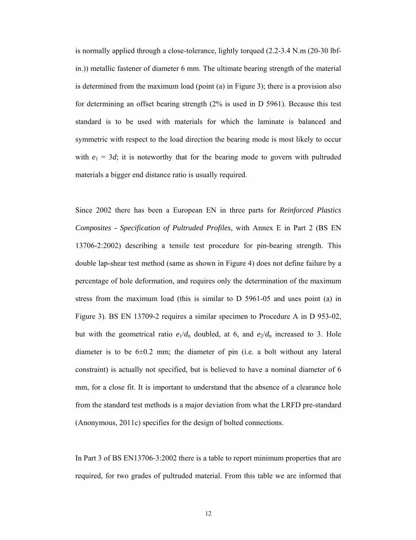
is normally applied through a close-tolerance, lightly torqued (2.2-3.4 N.m (20-30 lbf-
in.)) metallic fastener of diameter 6 mm. The ultimate bearing strength of the material
is determined from the maximum load (point (a) in Figure 3); there is a provision also
for determining an offset bearing strength (2% is used in D 5961). Because this test
standard is to be used with materials for which the laminate is balanced and
symmetric with respect to the load direction the bearing mode is most likely to occur
with e1 = 3d; it is noteworthy that for the bearing mode to govern with pultruded
materials a bigger end distance ratio is usually required.
Since 2002 there has been a European EN in three parts for Reinforced Plastics
Composites - Specification of Pultruded Profiles, with Annex E in Part 2 (BS EN
13706-2:2002) describing a tensile test procedure for pin-bearing strength. This
double lap-shear test method (same as shown in Figure 4) does not define failure by a
percentage of hole deformation, and requires only the determination of the maximum
stress from the maximum load (this is similar to D 5961-05 and uses point (a) in
Figure 3). BS EN 13709-2 requires a similar specimen to Procedure A in D 953-02,
but with the geometrical ratio e1/dn doubled, at 6, and e2/dn increased to 3. Hole
diameter is to be 6±0.2 mm; the diameter of pin (i.e. a bolt without any lateral
constraint) is actually not specified, but is believed to have a nominal diameter of 6
mm, for a close fit. It is important to understand that the absence of a clearance hole
from the standard test methods is a major deviation from what the LRFD pre-standard
(Anonymous, 2011c) specifies for the design of bolted connections.
In Part 3 of BS EN13706-3:2002 there is a table to report minimum properties that are
required, for two grades of pultruded material. From this table we are informed that

13
the minimum pin-bearing strengths of br0F and br
90F (in N/mm2) are 150 and 70 for
Grade 23, and 90 and 50 for Grade 17 (the material grade number gives the minimum
longitudinal tensile modulus of elasticity or LengthWise tensile modulus). It may be
assumed that the higher material grade is for structural shapes and that the lower is for
flat sheets; although this association is not strong.
The two American standards and the single European standard recommend a sample
size of five; which is not large when a statistical analysis (ASTM D 7290-06 (2006)
requires a minimum of ten specimens per batch) is required to establish a
characteristic strength. Because the three standard test methods were not written
concurrently with the drafting of a structural standard for the design of pultruded FRP
structures their specifications ensure that some required (pin) bearing strengths cannot
be measured and when they can be, they may not be acceptable for brF in Equation
(1). The reasons for this finding will further be developed and discussed in the rest of
this paper.
Having reviewed what the three standard test methods offer a valid test method
requires a relevant definition for the failure load. Earlier in the historical review the
seven different failure load definitions from Johnson and Matthews (1979) are listed.
Failure loads (d) to (g) have not been observed with pultruded materials when the test
method is for the pin-bearing strength. Failure load (c) is dependent on the length of
gauge used to measure hole elongation and at 4% (for D 953) the elongation can be
too high for pultruded materials. Testing for br0F always gives load-stroke plot curves
without a failure load (b), and so by virtue of elimination the pin-bearing strengths for
Equation (1) in the LRFD pre-standard chapter should always be determined using

14
failure load (a), the maximum load (it is usually the load for failures giving failure
loads, (b), (e) and (f)). This complies with what is required by testing to ASTM D
5961-02 and BS EN 13706-2:2002.
A Test Method for Pultruded Structural Shapes
To be able to characterise the pin-bearing strength for the LRFD pre-standard it will
be necessary to test with pin sizes up to the maximum permitted bolt diameter.
Applying any of the three test methods introduced above it will be necessary, when
the bolt diameter is 25.4 mm (1 in.), for the length of the double-lap specimen (see
item 6 in Figure 4) to be 300 mm or higher. For this biggest bolt diameter the
specimen width ought to be 150 mm (i.e. 6d). Such a specimen size (0.3 by 0.15 m)
can readily be cut from ‘off-the-shelf’ flat sheets (Anonymous, 2011a,b) of 1.828 by
1.21 m (6 ft. by 4 ft.) to determine brF for any orientation required. This specimen
size, however, cannot readily be accommodated in the longitudinal direction ( = 0o)
with many structural shapes (see Figure 1 and examples in Turvey (2000), Bank
(2006) and Anonymous, (2011a,b)), and definitely is far too big, and remains so, even
with the smallest bolt diameter of 9.53 mm (3/8 in.), when the direction of loading is
in the transverse direction (for = 90o).
To overcome the tensile specimen dimension limitation when characterising
orthotropic material from a structural shape (or profile in EN 13706) Clause 6 to the
Preparation of plates and test specimens in Part 2 of EN 13706 gives “…a test plate
can be used to simulate the pultrusion for the determination of the laminate properties
for design…” To the authors’ knowledge this approach is not practiced and so a test

15
method is very desirable that has a reduced specimen size to remove the dimension
limitation with the tensile specimen of the current standard test methods.
A preliminary study by Mottram (2009) presents a comparison for a longitudinal pin-
bearing strength ( br0F ) determined using two test methods. One is in the spirit of EN
13706-2 (Figure 4) and the second, using the test arrangement shown in Figure 5,
requiring a much smaller compression specimen is found to be in the spirit of the
timber test method ASTM D 5764-97a (reapproved 2007). The load arrangement has
previously been used by Wang et al., (1996) to characterise bearing strengths of
laminated FRPs for the aerospace industry. The Warwick University test arrangement
is shown in Figure 5. It is based on compressing a pin into a small rectangular
specimen with a semi-circular notch held vertically by a specimen holder having
uniform grooves in the side walls to accommodate the material thickness. This
approach to apply the pin bearing force removes the tensile specimen size problem.
Mottram (1994) gives a description of how the compression ‘die set’ in Figure 5 is
used to subject a compression coupon to pure compression for determination of
compression strength.
The material, of nominal thickness 6.35 mm (1/4 in.), was pultruded by Creative
Pultrusions Inc. (Anonymous, 2011a) and is from the 1625 series of flat sheets. It
consists of E-glass fibre reinforcement in a thermoset Vinyl Ester (Class 1 FR) based
matrix. This series of flat sheets, with thicknesses from 3.18 mm (1/8 in.) to 25.4 mm
(1 in.), have the following reported mechanical properties in the longitudinal (0o or
LengthWise) direction: compression modulus (D 695) = 12.4 kN/mm2; compression

16
strength (D 695) = 165 N/mm2; bearing strength (D 953) = 220 N/mm2 (it is actually a
pin-bearing value).
The number of nominally identical specimens per batch of specimens was six
(Mottram, 2009). There were twelve batches, six for each of the two test
arrangements, and with the six comprising of the three pin diameters (d) of 8, 12 and
16 mm, with and without a hole clearance of nominally 1 mm (which is 0.6 mm
below the minimum value given in the LRFD pre-standard). The actual measured
mean diameters (d) of the pins, cut from metric steel bolts (Grade 8.8), were 7.84,
11.84 and 15.8 mm. The six nominal hole diameters (dn) were 8, 9, 12, 13, 16 and 17
mm and their mean measured values were (to nearest 0.05 mm) 7.75, 8.80, 11.80,
12.8, 15.7 and 16.8 mm, respectively. Note that tolerances in drilling mean the holes
were undersized by up to 0.3 mm. In Mottram (2009) each batch was labelled, with
WU09 for specimens having a 9 mm diameter hole, loaded with the Warwick
University (WU) test arrangement of Figure 5, while EN17 is for the 17 mm hole
diameter, loaded using the EN 13760 test arrangement (Figure 4). Specimen
thicknesses were measured to the nearest 0.05 mm with an outside micrometer, and t
was found to range between 6.10 and 6.60 mm.
Figure 5 shows the in-house compression ‘die set’ (Mottram, 1994) with fixtures and
steel pin to apply compressive loading into a semi-circular notched rectangular
specimen. The specimen holder for the 6.35 mm thick plate required a specimen
width of 73 mm (Lutz, 2005). For this preliminary study, the height of a specimen
was set at 6d, so that for the WU16 specimen shown in Figure 5 this dimension is 96
mm. Load was applied under a constant stroke rate of -0.01 mm/s using a DARTEC

17
9500 hydraulic testing machine with a ±250 kN load cell. To establish the maximum
compressive force at failure, 0.165 kN was added to the maximum machine reading to
allow for the dead weight of the top plate and rocker transfer fixture (not shown in
Figure 5). For the EN testing the tension loading to the double lap-shear specimen
(like Figure 4) was applied using a constant stroke rate of 0.01 mm/s. The duration of
each static strength test to failure load (a) (in Figure 3) was between 60 and 90
seconds.
Presented in Tables 1 and 2 is a summary of the br0F results from this first series of
tests, with Table 1 for the WU batches and Table 2 for the equivalent EN batches.
Batch mean, Standard Deviation (SD) and Coefficient of Variation (CV) are given on
the assumption that the strength population fits the Gaussian distribution.
Characteristic values for br0F are determined using the guidance in Annex D7 to
Eurocode 0 (BS EN 1990:2002), and they may be associated with the characteristic
strength for Equation (1) in the LRFD pre-standard (Anonymous, 2011c). Both BS
EN 1990:2002 and the commentary by Gulvanessian et al. (2002) on Eurocode 0 give
details on how characteristic properties are to be determined. The CV is typically
between 5 and 10% and this justifies calculating the characteristic strength on the
assumption that the coefficient of variation is know a priori. A full discussion on the
findings from this series of tests is to be found in Mottram (2009).
To have the confidence to continue characterising pin-bearing strengths using the
Warwick University test arrangement it is imperative to be confident that the two
methods do not give significantly different strength measurements. In Figure 6 the
characteristic values from Tables 1 and 2 are plotted against the bolt diameter-to-
18
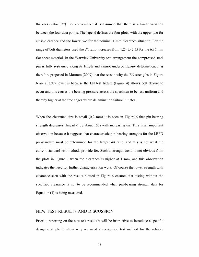
thickness ratio (d/t). For convenience it is assumed that there is a linear variation
between the four data points. The legend defines the four plots, with the upper two for
close-clearance and the lower two for the nominal 1 mm clearance situation. For the
range of bolt diameters used the d/t ratio increases from 1.24 to 2.55 for the 6.35 mm
flat sheet material. In the Warwick University test arrangement the compressed steel
pin is fully restrained along its length and cannot undergo flexure deformation. It is
therefore proposed in Mottram (2009) that the reason why the EN strengths in Figure
6 are slightly lower is because the EN test fixture (Figure 4) allows bolt flexure to
occur and this causes the bearing pressure across the specimen to be less uniform and
thereby higher at the free edges where delamination failure initiates.
When the clearance size is small (0.2 mm) it is seen in Figure 6 that pin-bearing
strength decreases (linearly) by about 15% with increasing d/t. This is an important
observation because it suggests that characteristic pin-bearing strengths for the LRFD
pre-standard must be determined for the largest d/t ratio, and this is not what the
current standard test methods provide for. Such a strength trend is not obvious from
the plots in Figure 6 when the clearance is higher at 1 mm, and this observation
indicates the need for further characterisation work. Of course the lower strength with
clearance seen with the results plotted in Figure 6 ensures that testing without the
specified clearance is not to be recommended when pin-bearing strength data for
Equation (1) is being measured.
NEW TEST RESULTS AND DISCUSSION
Prior to reporting on the new test results it will be instructive to introduce a specific
design example to show why we need a recognised test method for the reliable
19
determination of pin-bearing strength of pultruded materials. Later we shall return to
this example to examine it with the new strength data. Figure 1 shows a typical web
cleat connection (Anonymous, 2011b) for a beam member of the Wide Flange shape
of size 203 x 203 x 9.35 mm (8 x 8 x 3/8 in). This type of beam-to-column joint is
covered by the design clauses in the bolted connection chapter to the LRFD pre-
standard (Anonymous, 2011c). When checking the resistance of the web cleat
connection it is assumed that the vertical shear force from the beam loading splits
equally between the two bolts and the relevant pin-bearing strength is br90F . Page 8-14
of the Strongwell Design Manual (Anonymous, 2011b) has a load table for this
standard structural shape when used as a simply supported beam having a uniformly
distributed load. For a span of 4 m (i.e. 13 ft) and a maximum allowable central
deflection of span/150 the end shear force is 8.85 kN. Assuming the two steel bolts
take equal shear force and have the smallest diameter (d) of 9.53 mm (3/8 in.), the
web has a mean thickness (t) of 9.1 mm (from Tables 3 to 5) the required design br90F is
found to be 51 N/mm2. This reduces to 32 N/mm2 if the serviceability limit on linear
elastic deflection is set to span/240. The design manual also allows for bolting with
bolts of 12.7 mm (1/2 in.) or 15.8 mm (5/8 in.) sizes and the required pin-bearing
strength will reduce. The required strength for the web cleats is significantly lower
because, at each bolt level, the nominal cleat thickness is nearly 2.7 times greater than
the thickness of the web. br0F is, however, to be the pin-bearing strength when
checking the web cleats for bearing failure and when the designer calculates the tying
force resistance for the beam’s bolted connection.
Test results for 0o, 45o and 90o material orientations (Figure 1) are obtained from a
series of pin-bearing strength tests using the WU test arrangement shown in Figure 7.
20
The test procedure is that given earlier and in Mottram (2009). This test method is
required because the specimens are cut from the web of a 203 x 203 x 9.53 mm Wide
Flange shape having a depth of 180 mm. The shape is from Creative Pultrusions Inc.
(Anonymous, 2011a) and the standard 1525 series product range with a fire retardant
matrix, comprising a filled isophthalic polyester polymer. The 1525 series shapes are
coloured gray. The material has the following reported mechanical properties
(Anonymous, 2011a):
in the longitudinal (0o or LengthWise) direction - compressive modulus
(D695) = 20.7 kN/mm2; compression strength (D 695) = 231 N/mm2;
maximum bearing strength (LW),br
0F (D 953) = 206 N/mm2.
in the transverse (90o or CrossWise) direction - compressive modulus (D695)
= 7.0 kN/mm2; compression strength (D 695) = 115 N/mm2; maximum
bearing strength (CW),br
90F (D 953) = 124 N/mm2.
These mechanical properties from the pultruder are averages based on random
sampling and testing of production lots for the series range of shape. As a
consequence of their provenance they cannot be linked directly to specific shapes,
such as those shown in Figure 1. In the Design Manual (Anonymous, 2011a) the
longitudinal pin-bearing strength br0F is defined as the Maximum Bearing Strength
(LW). There are no accompanying notes to explain why the word ‘Maximum’ is used.
D953 does define maximum bearing stress to be the maximum load in newtons (or
pounds-force) sustained by the specimen, divided by the bearing area. This is not
what D953 defines as bearing strength, which is the bearing stress at which the
bearing hole is deformed 4% of its diameter. Because Creative Pultrusions Inc. used
the standard test method ASTM D 953 the word ‘Bearing’ ought to be ‘Pin-bearing’.

21
Such a casual choice of words in the Design Manual (Anonymous, 2011a) is not
helpful to practitioners; it is an example of the numerous gaps in knowledge that led
the PIC of ACMA to support the project for the preparation of the LRFD pre-standard
(Anonymous, 2007, 2011a).
It is also of interest to observe that if we assume the material of the Wide Flange
shape is classified as Grade 23, BS EN 13706-3:2002 says the minimum longitudinal
( br0F ) and transverse ( br
90F ) pin-bearing strengths are 150 and 90 N/mm2, respectively.
The Creative Pultrusion Inc. values at 206 and 124 N/mm2 are seen to 38% higher.
They were obtained in-house in accordance with test method ASTM D 953 and a
bearing failure load for a 4% hole elongation, which we have already exposed
weaknesses in determining pin-bearing strength.
Micromechanical modelling can be used to estimate the elastic moduli of a pultruded
material. Volume fractions of the constituents are obtained by using the resin burn-off
method. Lane (2002) took the constituent properties for the E-glass and polyester
matrix and used micromechanical modelling to estimate that the web material in the
Wide Flange shape has a longitudinal modulus of elasticity of 17 kN/mm2 and a
transverse modulus of 10 kN/mm2. This theoretically derived longitudinal modulus is
significantly lower than the 24.3 kN/mm2 measured by strain gauging (Lane, 2002)
and the higher modulus, for the flange material in the same shape, of 26.0 kN/mm2
using micromechanical modelling (Lane, 2002). This difference in longitudinal
modulus of elasticity between flanges and web is because the web material has less
UD rovings per unit area and to compensate a greater volume fraction of CSM
reinforcement than in the flanges.

22
The test results are presented in Tables 3 and 5. In this series of tests the number of
nominally identical specimens per batch is six when the loading is either at 45o or 90o
to the direction of pultrusion. For the tests with the load at 0o the batch size is bigger
at 11. For each of the three material orientations there are four batches, comprising the
following pairs of nominal hole diameters (dn) and nominal pin diameters (d): 11.8
and 9.7 mm; 14.8 and 12.7 mm (1/2 in.); 20.9 and 18.8 mm (3/4 in.) and 27.9 and
25.4 mm (1 in.). The four pins were cut from standard steel (Grade 8.8) bolts. The
mean measured diameters (d and dn) and mean hole clearances (dn – d) to nearest 0.1
mm are given in rows two to four in Tables 3 to 5. Because of available diameters of
the drill bits it is to be noted that the minimum clearance of 1.9 mm is greater than the
minimum 1.6 mm (1/16 in.) required by the LRFD pre-standard; we can therefore
expect pin-bearing strength measurements to be on the lower side of their values that
can be used with Equation (1).
Mean web thickness per specimen was measured to the nearest 0.05 mm with an
outside micrometer, and t is found to have mean specimen values in the range of 9.07
to 9.18 mm. The mean thicknesses per batch of six or 11 specimens are given in the
first row in Tables 3 to 5.
Figure 7 shows a second in-house compression ‘die set’ arrangement for testing that
applies the pure compressive bearing load through a pin. The ‘die set’ and specimen
holder are bigger than those for the same test arrangement shown in Figure 5, and the
specimen holder (for nominally 9.53 mm thick material) requires a specimen with a
width of 100 mm. By inspection of the surface texture of the specimen in Figure 7 it
can be seen that the material orientation is 45o. Because bearing failure is known to

23
occur (Lutz, 2005; Wang, 2004) when the end distance (e1) of the tensile specimen
(Figure 4) is 4d or higher, the specimen height for all four pin diameters is set at 100
mm (i.e. 4 25 mm). To achieve this height the blanks cut from the web had to be
125 mm long to accommodate drilling for the 28 mm diameter hole. It is noteworthy
that the 4590o blanks of 125 by 100 mm for the WU test method (Figure 7) can
readily be cut from the 180 mm deep web of the Wide Flange shape.
Load is applied under a constant stroke rate of -0.01 mm/s using a DARTEC 9500
hydraulic testing machine with a ±250 kN load cell. To establish the maximum
compressive force at failure, 0.338 kN is added to the maximum machine reading to
allow for the dead weight of the top plate and rocker transfer fixture (not shown in
Figure 7). A Solartron SI 3531 data acquisition system is used to monitor the load and
stroke in real time, at the rate of one pair of readings every two seconds. To reach the
maximum load the duration of testing can be 110 seconds.
Tables 3 and 5 present a summary of test results, with, respectively, the table ordering
for longitudinal (0o), 45o and transverse (90o) material orientations. The number of
specimens per batch is given in row five. For each batch the mean, Standard
Deviation (SD) and Coefficient of Variation (CV) are given in rows six to eight on the
assumption that the strength population fits the Gaussian distribution. Characteristic
values in row nine of the tables are determined using the guidance in Annex D of
Eurocode 0 (Gulvanessian et al., 2002), and they may be associated with a
characteristic strength for Equation (1). Because CV typically lies between 5 and 10%
it was acceptable to calculate the characteristic strength on the assumption that the

24
coefficient of variation is known a priori. The final row entries in the tables give the
pin diameter-to-material thickness ratios.
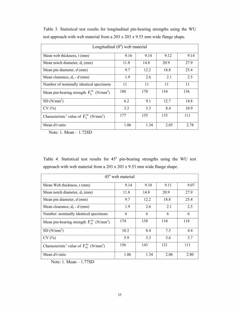
It is seen from the results in Table 1 that the minimum mean br0F of 136 N/mm2 is
below the BS EN 13706-3:2002 minimum required strength of 150 N/mm2 (for Grade
23 material). An even less favourable finding is that the minimum characteristic value
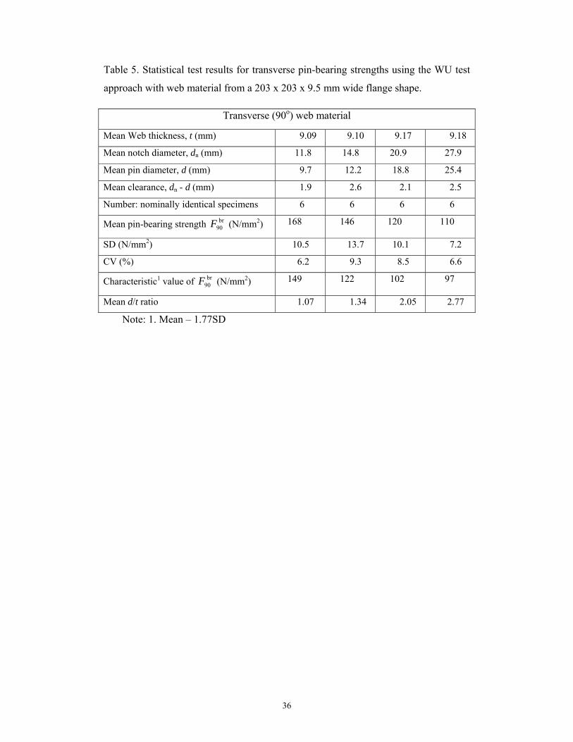
of 111 N/mm2 is 26% below this EN minimum. For br90F the minimum mean and
characteristic values of 110 N/mm2 and 97 N/mm2, respectively, are found to be well
in excess of the EN 13706-3:2002 minimum of 70 N/mm2.
Figures 8 to 10 presents pin-bearing stress (calculated using Rbr,test/td, where Rbr,test is
the test compressive force (see Figure 7)) against stroke plots. The stroke is that
measured by the DARTEC 9500 testing machine and because of the much higher
axial stiffness of test fixtures, steel pin, and testing machine this stroke is dominated
by the compressive deformation of the (100 – dn/2) mm high FRP specimen. When
the compressive load is aligned with the pultrusion direction it has been previously
found (Mottram, 2009) that the load-stroke curves are virtually linear to maximum
load, and that there is a sudden load reduction as significant bearing failure occurs.
This justifies the choice of failure load (a) in Figure 3, from Johnson and Matthews
(1979), for calculating pin-bearing strength. The typical plots for stress against stroke
in Figures 8 and 9 are therefore for the newer load cases when Rbr,test is acting
transverse (90o) or 45o to the pultrusion direction. As expected, the sudden reduction
in load at onset of bearing failure is less than when loading is in the 0o material
direction (Mottram, 2009). The curves in these two figures show that when the pin
diameter is 18.8 or 25.4 mm the curves are also fairly linear to the maximum load. For

25
the smaller pin diameter of 12.2 mm this is also found for the 45o loading case. For
this pin size and 90o loading, and for the smallest pin diameter of 9.7 mm, with both
45o and 90o loading cases, the three curves show a form of ductility with the
maximum load higher than at first peak. Figure 8 shows that the maximum load is
more than just slightly higher for the specimen with the 9.7 mm pin. This is the only
specimen out of 92 in the test series where the failure load could be defined by point
(b) in Figure 3; the other 91 can be defined by the maximum load.
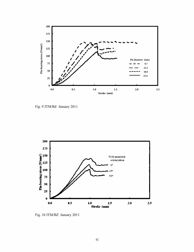
Plotted in Figure 10 are typical stress-stroke curves at the three material orientations
of 0o, 45o and 90o for a specimen with the 25.4 mm pin and 28 mm hole diameters.
Their characteristics are similar with the maximum load occurring at a stroke of about
1.0 mm and in descending magnitude with increasing material orientation. After the
initial embedding stage, the slope of the linear part of load-stroke curve should be
proportional to the modulus of elasticity. The ratio of gradients (for stroke between
0.4 and 0.8 mm) for the 0 and 90o tests is 1.72; very close to 1.7 given by the moduli
for the web material reported from micromechanical modelling by Lane (2002). Using
the gradient for the 45o specimen in Figure 10 it is estimated that the 45o modulus of
elasticity is 11.2 kN/mm2, which is 12% higher than in the transverse direction. For
the pin-bearing strengths, not governed by the UD roving reinforcement, we find the
ratio br90
br45 F/F is 1.13 using the mean of the four characteristic strengths in Tables 4
and 5. This suggests that for orientations away from 0o there might be a correlation
between the modulus of elasticity and the pin-bearing strength.
In Figure 11 the characteristic strengths in Tables 3 to 5 are plotted against the bolt
diameter-to-material thickness ratio (d/t). It is assumed that there is a linear variation

26
between the data points. The legend defines the three plots for material orientations of
0o, 45o and 90o. The d/t ratio increases from 1.06 to 2.80 (final row in the tables).
Now, when there is a hole clearance present the pin-bearing strength, c.f. with
equivalent curves in Figure 6, is seen to reduce with increase in d/t, thereby adding
evidence (Mottram 2009) to the requirement that a characteristic strength for Equation
(1) must be determined using the most severe design parameters found in practice. We
find therefore that reliability in establishing Rbr with Equation (1) cannot be assured
when pin-bearing strength is determined by rigorously complying with the standard
test methods of ASTM D 953-02 or BS EN 13706-2:2002. The trend of the strength
decrease in Figure 11 might be linear, but confirmation of this useful observation for
reducing the amount of testing to characterise the strength requires more results.
Yuan et al. (1996) conducted tests to show that by increasing hole clearance up to
50% of pin diameter (12.7 mm) the bearing strength was still reducing. For pin-
bearing test results reported in Tables 3 to 5 the available drill bits meant the
clearance sizes, as a percentage of pin diameter, were 20, 21, 11 and 10 for the bolt
(pin) diameters of 9.7, 12.2, 18.8 and 25.4 mm. It is therefore likely that
measurements for the two smaller bolt sizes are relatively lower than what has been
measured for the two bigger bolt sizes. This observation suggests that to establish a
trend, if, indeed, it exists, between pin-bearing strength and the d/t ratio, testing
should be performed with a clearance size that is set at a constant percentage (say
10%) of the pin diameter, for all bolt sizes. When using the historical review to
introduce what is permitted in the LRFD pre-standard (Anonymous, 2011c) the
authors stated that the minimum clearance hole size is 1.6 mm (1/16th in.) for bolts
from 9.53 (3/8 in.) to 25.4 mm (1 in.). On the assumption that the clearance remains

27
constant the reduction in strength is therefore largest for the smallest bolt size and this
influence is hidden as bolt diameter increases because the strength will decrease as d/t
increases.
Returning to the design checks for the web in the beam of Figure 1 the required
design pin-bearing strength ( br90F ) was earlier estimated to be 51 N/mm2, for a central
deflection of span/150. For the 9.7 mm bolt size the results in Table 5 say the
characteristic br90F is 149 N/mm2. Given that the required design value is about 1/3rd of
what is available, this single design comparison does not immediately raise alarm
bells over the reliability of the ‘room temperature’ load table for 203 x 203 x 9.53 mm
shape in the Strongwell Design Manual (Anonymous, 2011b). The Strongwell Wide
Flange shape will possess the same mechanical properties as the equivalent standard
section from Creative Pultrusions Inc. It is noteworthy that should the minimum
characteristic br90F of 97 N/mm2 be used in design calculations the level of reliability
will reduce significantly, and this is without any strength reduction due to service life
affects (such as from cyclic loading and/or environmental degradation).
Another finding from this series of tests is that the maximum transverse pin-bearing
strength of 124 N/mm2 (D 953), taken from the Creative Pultrusion Inc. Design
Manual (Anonymous, 2011a) is 30% higher than the lowest characteristic strength
entry in Table 5.
As expected the highest strength is in the longitudinal direction and as seen in Figure
11 the decrease of br0F with d/t is the most dramatic. Whereas Creative Pultrusion Inc.

28
state that the maximum bearing strength (LW) for the Wide Flange shape is 206
N/mm2, the characteristic results in Table 3 show it can be much lower (up to 46%)
and this must be accounted for should bearing failure govern the tying force
requirement of a beam’s joint. A reason for the significant difference in strength when
the bolt diameter is 25.4 mm is that the standard test method ASTM D 953 does not
require a clearance hole and the d/t ratio is specified to be 1.0.
Because we do not have details on how the Creative Pultrusion Inc. Design Manual
maximum bearing strengths were established the authors cannot provide an exact
explanation for the difference with the new results. What can be said is that there are a
number of differences in how the pin-bearing strengths were measured and that the
test approach for br0F and br
90F in this paper is the one that is representative of the
geometry of bolted connections found in practice.
Depending on how orthotropic the pultruded material is, it was believed (Mottram,
2009) that the strength ratio br90
br0 F/F lies within the range 1.2 to 1.5. From the
characteristic strengths reported in Tables 3 and 5 the lowest value to the ratio
br90
br0 F/F is 1.13 (mean of the four values is 1.23), and this ratio is lower than the
previously understood lower bound ratio of 1.2 (Mottram, 2009). Given that the ratio
of the directional modulus of elasticity is 1.7 (Lane, 2002) it is observed that this pin-
bearing strength ratio is not proportional to the modulus ratio. An explanation for this
finding could be that the mechanism for the bearing mode of failure has changed with
orientation, and this finding is the subject of new research.
CONCLUDING REMARKS

29
A historical review of the standard test methods (ASTM D 953-02 and EN 13706-
2:2002) used to determine the bearing strength of pultruded fibre reinforced polymer
materials in structural shapes has been used to expose their limitations in the context
of obtaining reliable and relevant strengths for the design of bolted connections. It is
observed that these standards do not require the strength to be determined when there
is a clearance hole, and for the much larger material thicknesses and bigger bolt sizes
found in practice. Another finding from the review of standard test methods is that the
size of the tension specimens is too large for it to be cut from pultruded shapes. An
alternative test arrangement, with a smaller specimen size, is therefore needed if all
pin-bearing strengths required to design bolted connections are to be determined.
To account for all possible influences on lowering the bearing strength of the
pultruded material, by the end of a structure’s service life, the authors recommend that
the pin-bearing strength (determined with no lateral restraint from tightening the nut
and bolt) should be used in calculations for the strength of bolted connections.
A comparison is reported by Mottram (2009) for pin-bearing strengths determined
using the larger tensile specimen with the test method EN 13706-2:2002 and the
smaller compression specimen with the Warwick University test method, the latter
loading approach is linked to ASTM D 5764-97a for evaluating dowel-bearing
strength of wood and wood-based products. Building on this previous study, a new
series of tests have been conducted to characterise the web material in a 203 x 203x
9.5 mm Wide Flange shape from the pultruder Creative Pultrusion Inc. Testing is
performed on batches of specimens with the loading oriented at 0o, 45o or 90o to the
direction of pultrusion. If this characterisation had been constrained by the need to use

30
a tensile specimen (for D 953 or EN 13706) the specimen size would have only
allowed the longitudinal (0o) pin-bearing strength to be determined.
Salient test results are presented and characteristic strengths are calculated in
accordance with Eurocode 0. The bolt diameter-to-material thickness ratio is varied
from 1.06 to 2.80, and the clearance hole is a minimum of 1.9 mm. Plots for the
characteristic strength for the three orientations highlight its decrease as this ratio
increases. The trend might be linear, but confirmation requires more test results (and
with a minimum of 10 nominally identical specimens per batch). It is found that the
minimum characteristic strengths are obtained with the biggest steel bolt diameter of
25.4 mm. The maximum (0o or longitudinal) and minimum (90o or transverse)
characteristic strengths at 111 and 97 N/mm2, respectively, cannot easily be compared
with the maximum (pin) bearing strengths of 206 and 124 N/mm2, respectively,
tabulated in the Creative Pultrusion Inc. Design Manual (Anonymous, 2011a). What
is known is that there are significant differences in how the pin-bearing strengths were
measured by Creative Pultrusions Inc. and the authors, and that the test approach used
in this paper is the one that represents the geometry of bolted connections found in
practice.
The main finding from this study towards the determination of pin-bearing strength is
that it is necessary to relax the requirements specified in the standard test methods (D
953 or EN 13706) currently used by pultruders and researchers. To be able to measure
every characteristic strength used in design it will be necessary to apply a test
methodology similar to that used by the authors, and to ensure that the test matrix
involves material orientations and thicknesses, and pin and hole diameters found in

31
practice. A recommended test matrix can be established by way of the scope
permitted in the bolted connection chapter to the future LRFD standard (Anonymous,
2011c). It is further recommended that the minimum batch size be set at 10 and that
characterisation must involve environmental conditioning that will encompass the
likely forms of material degradation in the region of the bolt holes over the intended
service lives of pultruded FRP structures.
ACKNOWLEDGMENTS
In preparing the specimens the authors acknowledge the technical support given to
this research by Mr C. Banks of the School of Engineering at the University of
Warwick.
References
Anonymous. (2007). ACMA develops design standard for civil engineers. Reinforced
Plastics 51, No. 9, 12.
Anonymous. (2011a). The New and Improved Pultrex® Pultrusion Design Manual
(Metric version). Creative Pultrusions, Inc., Alum Bank, PA.
//www.creativepultrusions.com/rd.html (Literature library) 21st January 2011
Anonymous. (2011b). Strongwell Design Manual. Strongwell, Bristol, VA.
//www.strongwell.com/ (Literature) 21st January 2011
Anonymous. (2011c). New Pre-Standard for Pultruded FRP Composites Funded thru
ACMA Means Increased Applications, American Composites Manufacturers
Association (ACMA) press release. //www.acmanet.org/pressreleases/2011/011711.html
21st January 2011
ASTM D 953–02. Standard Test Method for Bearing Strength of Plastics. American
Society for Testing and Materials International, West Conshohocken, PA, 2002.
ASTM D 5961-05. Standard Test Method for Bearing Response of Polymer Matrix
Composite Laminates. American Society for Testing and Materials International,
West Conshohocken, PA, 2005.
32
ASTM D 7290-06. Standard Practice for Evaluating Material Property
Characteristic Values for Polymeric Composites for Civil Engineering Structural
Applications. American Society for Testing and Materials International, West
Conshohocken, PA, 2006.
ASTM D 5764-97a (Reapproved 2007). Standard Test Method for Evaluating Dowel-
Bearing Strength of Wood and Wood-Based Products. American Society for Testing
and Materials International, West Conshohocken, PA, 2007.
Bank, L. C. Composites for Construction - Structural Design with FRP Materials,
John Wiley & Sons, New Jersey, 2006.
BS EN 1990:2002. Eurocode 0 - Basis of Structural Design, British Standards
Institution, United Kingdom, 2002.
BS EN 13706-2:2002. Reinforced Plastic Composites - Specification for Pultruded
Profiles - Part 2: Methods of Test and General Requirements. British Standards
Institution, United Kingdom, 2002.
BS EN 13706-3:2002. Reinforced Plastic Composites - Specification for Pultruded
Profiles - Part 3: Specific Requirements. British Standards Institution, United
Kingdom, 2002.
Cooper, C. & Turvey, G. J. (1995). Effects of joint geometry and bolt torque on the
structural performance of single bolt tension joints in pultruded GRP sheet material.
Composite Structures 32, Nos. 1-4, 217-226.
Gulvanessian, H., Galgaro, J-A. and Holický, M. (2002). Designers' Guide to EN
1990 Eurocode: Basic of Structural Design, Thomas Telford, London.
Johnson, M. & Matthews, F. L. (1979). Determination of safety factors for use when
designing bolted joints in GRP. Composites 10, No. 2, 73-76.
Lane, A. An Experimental Investigation of Buckling Mode Interaction in PFRP
Columns. PhD thesis, University of Warwick, UK, 2002.
Lutz, C. Structural Integrity of Bolted Joints for PFRP Profiles. PhD thesis,
University of Warwick, UK, 2005.
MIL-HDBK-17-3F. (2002). Composite Materials Handbook, Volume 3. Polymer
Matrix Composites: Materials Usage, Design and Analysis, Volume 3 of 5,
Department of Defense Handbook, USA.
Mottram, J. T. (1994). Compression strength of pultruded flat sheet material. Journal
of Materials in Civil Engineering 6 No. 2, 185-200.

33
Mottram, J. T. (2004). Friction and load transfer in bolted joints of pultruded fibre
reinforced polymer section. Proceedings of the 2nd International Conference on FRP
Composites in Civil Engineering, Adelaide, Australia, A. A. Balkema Publishers, 845-
850.
Mottram, J. T. (2009). Determination of pin-bearing strength for the design of bolted
connections with standard pultruded profiles. Proceedings of the 4th International
Conference on Advanced Composites in Construction (ACIC 2009), Edinburgh,
NetComposites Ltd., Chesterfield, 483-495.
Mottram, J. T. & Turvey, G. J. (2003). Physical test data for the appraisal of design
procedures for bolted joints in pultruded FRP structural shapes and systems. Progress
in Structural Engineering and Materials 5 No. 4, 195-222.
Thoppul, S. D., Finegan, J. & Gibson, R. F. (2009). Mechanics of mechanically
fastened joints in polymer-matrix composites – A review. Composites Science and
Technology 69, 301-329.
Turvey, G. J. (2000). Bolted connections in PFRP structures. Progress in Structural
Engineering and Materials 2, No. 2, 146-156.
Wang, H. S., Hung, C. L. & Chang, F. K. (1996). Bearing failure of bolted composite
joints, Part I: Experimental characterization. Journal of Composite Materials 30, No.
12, 1284-1313.
Wang P. Structural Integrity of Bolted Joints for Pultruded GRP Profiles. PhD thesis,
University of Lancaster, UK, 2004.
Yuan, R. L., Liu, C. J. & Daley, T. (1996). Study of mechanical connection for GFRP
laminated structures. Proceedings of the 2nd International Conference on Advanced
Composite Materials in Bridges and Structures (ACMBS-2), The Canadian Society
for Civil Engineers, Montreal, 951-958.

34
Table 1. Statistical test results for longitudinal pin-bearing strengths using the WU
test approach with 6.35 mm thick flat sheet material.
br0F Batches of six specimens
WU08 WU09 WU12 WU13 WU16 WU17
Mean (N/mm2) 362 241 315 227 314 239
SD (N/mm2) 21.6 25.2 10.0 24.5 31.0 17.0
CV (%) 6.0 10.5 3.2 10.8 9.9 7.1
Characteristic1
(N/mm2)
314 186 293 174 246 202
Mean d/t ratio 1.25 1.27 1.92 1.91 2.55 2.54
Table 2. Statistical test results for longitudinal pin-bearing strengths using BS EN
13706-2 test approach with 6.35 mm thick flat sheet material.
br0F Batches of six specimens, except for EN09 with five
EN08 EN09 EN12 EN13 EN16 EN17
Mean (N/mm2) 324 232 298 201 297 235
SD (N/mm2) 10.4 17.6 19.5 7.6 22.2 19.6
CV (%) 3.2 7.6 6.6 3.8 7.5 8.4
Characteristic1
(N/mm2)
301 191 255 185 245 192
Mean d/t ratio 1.23 1.25 1.92 1.88 2.51 2.49
Note: 1. Mean – 2.18SD.
35
Table 3. Statistical test results for longitudinal pin-bearing strengths using the WU
test approach with web material from a 203 x 203 x 9.53 mm wide flange shape.
Longitudinal (0o) web material
Mean web thickness, t (mm) 9.16 9.14 9.12 9.14
Mean notch diameter, dn (mm) 11.8 14.8 20.9 27.9
Mean pin diameter, d (mm) 9.7 12.2 18.8 25.4
Mean clearance, dn - d (mm) 1.9 2.6 2.1 2.5
Number of nominally identical specimens 11 11 11 11
Mean pin-bearing strength br0F (N/mm2) 188 170 154 136
SD (N/mm2) 6.2 9.1 12.7 14.8
CV (%) 3.3 5.3 8.4 10.9
Characteristic1 value of br0F (N/mm2) 177 155 133 111
Mean d/t ratio 1.06 1.34 2.05 2.78
Note: 1. Mean – 1.72SD
Table 4. Statistical test results for 45o pin-bearing strengths using the WU test
approach with web material from a 203 x 203 x 9.53 mm wide flange shape.
45o web material
Mean Web thickness, t (mm) 9.14 9.10 9.11 9.07
Mean notch diameter, dn (mm) 11.8 14.8 20.9 27.9
Mean pin diameter, d (mm) 9.7 12.2 18.8 25.4
Mean clearance, dn - d (mm) 1.9 2.6 2.1 2.5
Number: nominally identical specimens 6 6 6 6
Mean pin-bearing strength br45F (N/mm2) 174 158 134 118
SD (N/mm2) 10.3 8.4 7.5 4.4
CV (%) 5.9 5.3 5.6 3.7
Characteristic1 value of br45F (N/mm2) 156 143 121 111
Mean d/t ratio 1.06 1.34 2.06 2.80
Note: 1. Mean – 1.77SD
36
Table 5. Statistical test results for transverse pin-bearing strengths using the WU test
approach with web material from a 203 x 203 x 9.5 mm wide flange shape.
Transverse (90o) web material
Mean Web thickness, t (mm) 9.09 9.10 9.17 9.18
Mean notch diameter, dn (mm) 11.8 14.8 20.9 27.9
Mean pin diameter, d (mm) 9.7 12.2 18.8 25.4
Mean clearance, dn - d (mm) 1.9 2.6 2.1 2.5
Number: nominally identical specimens 6 6 6 6
Mean pin-bearing strength br90F (N/mm2) 168 146 120 110
SD (N/mm2) 10.5 13.7 10.1 7.2
CV (%) 6.2 9.3 8.5 6.6
Characteristic1 value of br90F (N/mm2) 149 122 102 97
Mean d/t ratio 1.07 1.34 2.05 2.77
Note: 1. Mean – 1.77SD

37
Figure Captions
Figure 1. Typical beam-to-column bolted joint for steel bolts of diameters 9.53 mm
(3/8 in.) to 15.9 mm (5/8 in.) based on engineering drawing on Page 19-6 of the
Strongwell Design Manual (Anonymous, 2011b).
Figure 2. Plate-to-plate distinct modes of failure with a single steel bolt; (a) bearing,
(b) net-tension, (c) shear-out, (d) cleavage.
Figure 3. Bearing load with measured extension showing seven ways to define failure
load, labelled (a) to (g), which can be used to determine a bearing strength (Johnson
and Matthews, 1979).
Figure 4. Steel tension loading fixture and FRP test specimen for D 953-02: 1 –
Hardened spacer plate; 2 – 6.35 mm steel bolts in reamed holes; 3 – Hardened side
plate; 4 – Extensometer span; 5 – Hardened steel pin in reamed hole; 6 – Test
specimen.
Figure 5. The smaller Warwick University (WU) pin-bearing strength test rig (from
Lutz, 2005).
Figure 6. Characteristic pin-bearing strengths (in N/mm2) of 6.35 mm series 1625 flat
sheet (Anonymous, 2011a) with d/t ratio, and with and without a 1 mm hole clearance.
Figure 7. The larger Warwick University (WU) pin-bearing strength test rig
(Mottram, 2009).
Figure 8. Pin-bearing stress (in N/mm2) with stroke (in mm) curves for transverse
orientation of the web material with four pin diameters from 9.7 to 25.4 mm.
Figure 9. Pin-bearing stress (in N/mm2) with stroke (in mm) curves for web material
oriented at 45o to load direction with four pin diameters from 9.7 to 25.4 mm.
Figure 10. Pin-bearing stress (in N/mm2) with stroke (in mm) curves for the web
material at the three orientation of 0o, 45o and 90o and pin diameter of 25.4 mm
(giving d/t = 2.78).
Figure 11. Characteristic pin-bearing strengths (in N/mm2) of 9.1 mm thick web
material with d/t ratio and hole clearance of 1.9 mm or larger.

38
25.4
76.2
25.4
44.4
203 x 203 x 9.53 WF
102 x 102 x 12.7 leg-angle
0o direction
90o direction45o direction
Fig. 1 JTM/BZ January 2011
Fig. 2 JTM/BZ January 2011

39
Bea
rin
g lo
ad
Measured extension (stroke)
a
bc
de
f
g
Fig. 3 JTM/BZ January 2011
5
1
2
3
4
6
d
e1
2e2
Fig. 4 JTM/BZ January 2011

40
73 mm
6d=
96
mm
Pin diameter 16 mm
Fig. 5 JTM/BZ January 2011
Fig. 6 JTM/BZ January 2011

41
100
mm
Fig. 7 JTM/BZ January 2011
0
25
50
75
100
125
150
175
200
0.0 0.5 1.0 1.5 2.0 2.5Stroke (mm)
Pin
-bea
ring
stre
ss (N
/mm
2 )
Fig. 8 JTM/BZ January 2011
42
0
25
50
75
100
125
150
175
200
0.0 0.5 1.0 1.5 2.0 2.5
Stroke (mm)
Pin
-bea
ring
stre
ss (N
/mm
2 )
Pin diameter (mm)
9.7
12.2
18.8
25.4
Fig. 9 JTM/BZ January 2011
Fig. 10 JTM/BZ January 2011

43
Fig. 11 JTM/BZ January 2011
End