Embed Size (px)
Citation preview

IntroductionTo
NDT
BY: Omid HEIDARY

NDT Methods
Penetrant Testing
Magnetic Particle Testing
Eddy Current Testing
Ultrasonic Testing
Radiographic Testing
Acoustic Emission
Infrared Testing
Visual Testing
Other methods

NDT
Which method is the best ?
Depends on many factors and conditions

NDT
Industries involved with NDT:
•Oil and Gas
•Construction
•Metal Fabrication
•Chemical
•Aerospace
•Power Generation
•Transportation
•Medical
•Electronic
•Metal Manufacturing
•Composite Manufacturing
•Inspection and Testing
•Research and Development
•Training and Certification

Penetrant Testing
Surface Testing method
For detecting surface breaking defects (opened to surface)
Applicable to all materials -except for excessively porous (absorbing) materials
Also known as Dye Penetrant Inspection (DPI)
Penetrant Flaw Detection (PFD)
Liquid Penetrant Inspection (LPI)

Basic Steps
•Penetrant application
•Removal of excess
penetrant
•Pre-cleaning
•Application of
Developer
•Inspection
•Post-cleaning

Penetrant Testing
• Penetrating fluid (penetrant) applied to
component
Aerosol Spraying
Immersion Brushing
Electrostatic

Advantages of PT
Applicable to non-ferromagnetics
Able to test large parts with a portable kit
Batch testing
Applicable to small parts with complex geometry
Simple,cheap easy to interpret
Sensitivity

Disadvantages of PT
Will only detect defects open to the surface
Careful surface preparation required
Not applicable to porous materials
Temperature dependant
Cannot retest indefinitely
Compatibility of chemicals

Magnetic Particle Testing

Test method for the detection of
surface and sub-surface defects
in ferromagnetic materials
Magnetic Particle Testing

Equipment

Depth below surface
SN SN

Ultrasonic Testing

Ultrasonic Testing
High frequency sound sound waves are introduced into a material
Reflected sound gives information on the material under test and signals displayed on a CRT
Principle

What is Sound ?
A mechanical vibration
The vibrations create Pressure Waves
Sound travels faster in more ‘elastic’ materials
Number of pressure waves per second is the ‘Frequency’
Speed of travel is the ‘Sound velocity’

Sound at an Interface
Sound will be either transmitted across or reflected back
Reflected
Transmitted
Interface
How much is reflected and
transmitted depends upon the
relative acoustic impedance of
the 2 materials
VZ acoustic impedance

Steel
AirSteel
Air
Steel
Steel Aluminum
Steel
Large Acoustic Impedance
Ratio
Large Acoustic Impedance
Ratio
No Acoustic Impedance
Difference
Small Acoustic Impedance
Difference

Snell’s Law
Perspex
Steel
C
CS
If the angle of Incident is
increased the angle of
refraction also increases
Up to a point where the
Compression Wave is at
90° from the Normal
90° This happens at the
FIRST CRITICAL ANGLE

Probes

Compression / Longitudinal
Vibration and propagation in the same direction / parallel
Travel in solids, liquids and gases
Propagation
Particle vibration

Shear / Transverse Vibration at right angles / perpendicular to
direction of propagation
Travel in solids only
Velocity 1/2 compression (same material)
Propagation
Particle vibration

Ultrasonic Displays A scan
The CRT (Cathode Ray Tube) display
The Horizontal axis :Represents time base / beam path length / distance / depth
The Vertical axis :Represent the amount of sound energy returned to the crystal
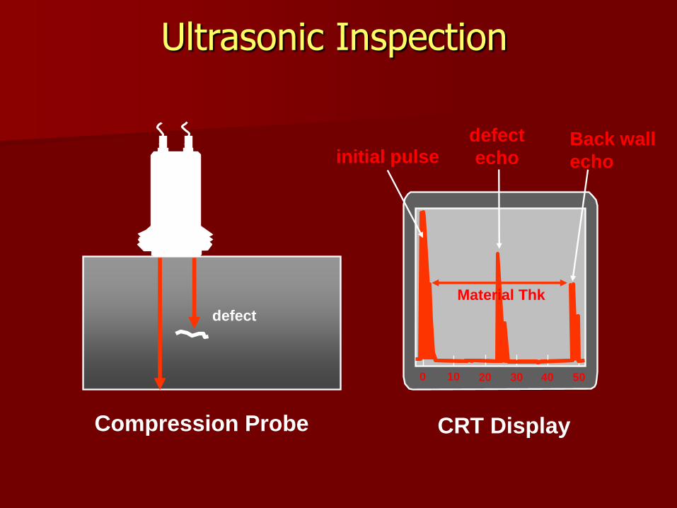
Ultrasonic Inspection
defect
0 10 20 30 40 50
defect
echoBack wall
echo
CRT DisplayCompression Probe
Material Thk
initial pulse

The depth of the defect can be read with reference
to the marker on the screen
0 10 20 30 40 50 60
60 mm

Thickness / depth measurement
A
A
B
B
C
C
The THINNER the material
the less distance the sound
travel
The closer the reflector
to the surface, the signal
will be more to the left of
the screen
The thickness is read from the screen
684630

Scanning Procedure
Parent Material
0 degree both sides
To maximum range for angle probes
Full skip distance for 60 or 70 probes

Scanning Procedure
Weld Root
Half skip from both sides
For PCN exams :
70 degree probe at half skip from both sides

Scanning ProcedureWeld Fusion Faces
Half to full skip from both sides
A probe which strikes fusion faces at 90 degrees
Probe angle = 90 - (1/2 Root angle)

Defect OrientationONLY DEFECTS HAVING A SUITABLY ORIENTATED
REFLECTING SURFACE CAN BE DETECTED BY PULSE ECHO METHODS!!
Orientation favourable, sound reflected back to
point of origin
Orientation unfavourable, sound not reflected back
to point of origin

Ultrasonic Displays
B scan
The End View Display
B
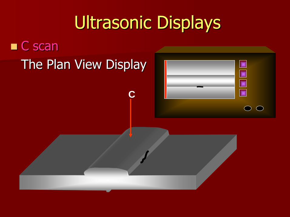
Ultrasonic Displays
C scan
The Plan View Display
C

Ultrasonic Displays
D scan
The Side View Display
D

Advantages of UT
Sensitive to cracks at various orientations
Portability
Safety
Able to penetrate thick sections
Measures depth and through wall extent

Disadvantages
No permanent record (unless automated)
Not easily applied to complex geometries and rough surfaces.
Unsuited to course grained materials
Requires highly skilled and experienced technicians

Radiographic Testing

Radiographic Testing
Electromagnetic radiation is imposed upon a test object
Radiation is transmitted to varying degrees dependant upon the density of the material through which it is travelling
Variations in transmission detected by photographic film or fluorescent screens
Applicable to metals,non-metals and composites

Shorter Wavelength = Increased Energy
Shortening Wavelength

10-10 10-8 10-6 10-4 10-2 1cm 102 104 106 108
Wavelength
Electric
Waves
TV
Microwaves
Infra
red
Ultra
violet
Industrial
radiography
Electromagnetic Spectrum

Re
lati
ve
Inte
ns
ity M
ev.
Gamma line spectrum (discrete energies), the wave
length is not of a fixed nature. A number of frequencies
will be emitted for most sources.
Long Short
Co 60
1.17 to1.3 Mev
Ir 192
0.3 to 0.47 MevYb 169
0.06 to 0.2 Mev
Wavelength l
Wavelengths
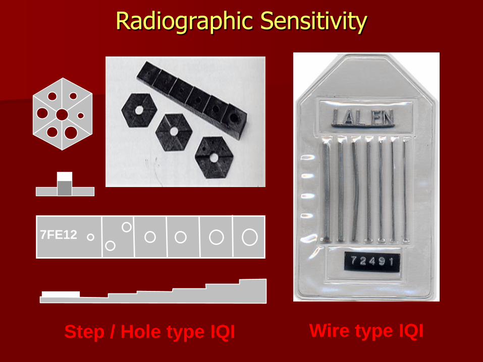
7FE12
Step / Hole type IQI Wire type IQI
Radiographic Sensitivity

Radiation beam
Radiographic Inspection
Test specimen
Image quality indicator
Source
Radiographic film

Film
Source
Low dense
discontinuity
High dense
discontinuity
Lighter
region on
radiograph
Darker
region on
radiograph
The basis of radiography

Source
Film
Thin part
Thick
part
Darker
region on
radiograph
Lighter
Region on
radiograph
The basis of radiography

Radioactive isotope
It is small,typically 1mm x 1.5 mm cylinders,that give off gamma rays
It occurs in nature and also in artificial isotopes
Artificial isotopes are created by bombarding an element with an excess of neutron in the nuclear reactor.
Example of nature isotopes are radium and uranium
Example of artificial isotopes are iridium 192 and cobalt 60

MEASUREMENT OF RADIOACTIVITY
THE BASIC UNIT IS CURIE
IN SI UNIT, IT IS MEASURED IN BECQUEREL
1 CURIE = 3.7 X 10¹⁰ BECQUERELS
HALF LIFE OF AN ISOTOPE IS THE
TIME IT TAKES FOR 1/2 OF THE ATOMS TO DECAY

RADIOGRAPHIC FILM
IT HAS TWO TYPES
SLOW FILM
-FINE GRAIN AND NEED MORE EXPOSURE
FAST FILM
- LARGE GRAINS AND NEED LESS EXPOSURE
KNOWLEDGE OF FILM CAN HELPS THE RADIOGRAPHER TO WORK OUT EXPOSURES WHEN CHANGING FILM BRANDS. E.G IN TABLE 5.3
FILM ALSO SHOULD BE STORED IN EDGES, IN COOL DRY CONDITIONS AND AWAY FROM CHEMICALS OR RADIATION

Radiographic
Techniques

IQI’s should be placed source side
Film
Film
Single Wall Single Image
SWSI

IQI’s are placed on the film side
Source inside film outside (single exposure)
Film
SWSI panoramic
Single Wall Single Image Panoramic

Film
IQI’s are placed on the film side
Source outside film outside (multiple exposure)
This technique is intended for pipe diameters over 100mm
Double Wall single Image
DWSI

Film
IQI’s are placed on the source or film side
Source outside film outside (multiple exposure)
A minimum of two exposures
This technique is intended for pipe diameters less than100mm
Double Wall Double Image
DWDI

Base
Subbing
Subbing
Emulsion AgBr
Emulsion AgBr
Supercoat
Supercoat
Radiographic Film

Dev
eloper
Sto
p
bat
h Running water
MANUAL SYSTERM
PROCESSING FILM

Advantages of Radiography
Permanent record
Detection of Internal flaws
Can be used on most materials
Direct image of flaws
Real - time imaging

Disadvantages of Radiography Health hazard
Sensitive to defect orientation
Limited ability to detect fine cracks
Access to both sides required
Limited by material thickness
Skilled interpretation required
Relatively slow
High capital outlay and running costs