Embed Size (px)
Citation preview

To: Dr. Lin and Dr. Momoh From: Ben Angel, Brandon Bodeker, Corey Delaney Date: 2/24/14 Re: Musical Tesla Coil Design Progress Report Report Outline
Report Summary
Problems And Corrections
Status Of The Machine
Supporting Information
Time Line For Completion
Block Diagram
Schematic
Parts List
Report Summary What you will find in the following report are updated designs and diagrams, our project Gantt chart, and the system simulations so far. Also is a brief description of any issues that have come up along the way and their corrections, what is the status of the machine and what is left to be done. The design phase is complete and we have moved onto circuit board creation to get ready for construction. Problems and Corrections Problems so far have included finding specific parts and dealing with Multisim. Not all the parts needed to build and test our designs are in Multisim or easily found and made to be added to Multisim. Not being able to get every part into our design as we needed it caused delays in being able to test and simulate some parts of the overall design. Also when we were ordering parts we have found some parts to be quite expensive and are trying to shop around for either cheaper options or better prices. Some parts on our list seem to be obsolete and not created any more sending us on huts to find reasonable alternatives. Status of the Machine Progress made so far includes circuit design and ordering parts. So far the designing of all individual circuits are complete. We have moved on to ordering parts to start building our designs. Currently we are testing and simulating the designs on Multisim to ensure their resilience as well as waiting for all the parts to arrive so that building and troubleshooting can begin. Supporting Information Primary/secondary voltages - In this particular case we use a pair of current transformers CT1 and
CT2. Both of them are a 1:33 ratio, and being cascaded, the final current reduction ratio is 1:1089 or
roughly 1:1000. The output of CT1 is loaded with a pair of zener diodes with ultrafast diodes to block
the slow recovery of the zeners. Since the transformer ratio is ~1:1000, by normal transformer action,
the current should be 1/1000th of the primary current, and the voltage should be 1000X greater.

How the feedback subsystem works – Our design will use a primary current feedback as the basis. The
way the design is set up, we could do a secondary base current feedback, but we have decided the
primary current feedback is the best option in our application. We are going to be using zener diodes to
cut the voltage from the coils to 0, 5, and 15v, which will give us a clipped sine wave (approximately a
square wave). A calculated resistance will then limit the current into a logic gate (currently undecided),
along with a few other supporting components. We will then pass our feedback signal through 2
inverters cleaning up our square and providing some hysteresis {This part refers to an analog filter. What
order is that?}. The signal is them passed on to the input of our gate drivers as well as the clock input for
a flip flop. The signal gets taken indirectly from an interrupter and gives an output that is synced up with
the clock input.
System Specifications Goals
Toroid
o Dimensions: 4’’ x 13’’
o Capacitance: 14.5pF
Secondary Coil
o Dimensions: 4.5’’ coliform x 18’’ length
o 1140 turns of 30 AWG
o Winding length: 12’’
o Ls: 48.87mH
o Rs: 134.9 Ohms
o Fres: 297kHz
Primary Coil
o Dimensions: 8’’ Diameter Solenoid Coil
o 6 turns of .25’’ copper tubing
o .2’’ conductor Spacing
Strike Rail
o Coil Diameter: 12’’
o # of Turns: .92
o Height: 3.2’’
o Conductor Diameter: .375’’
Time Line for Completion Present: 2/20/14 Finish design troubleshoot and board circuit board creation: 3/2/14 Finish building and troubleshooting individual circuits: 3/10/14 Finish integrating circuits and troubleshooting: 4/5/14
Formatted: Font color: Red
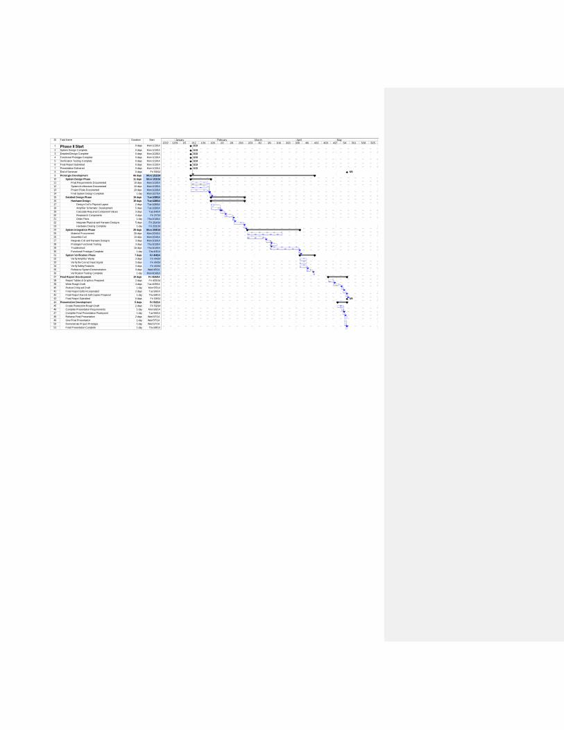
ID Task Name Duration Start
1 Phase II Start 0 days Mon 1/13/14
2 System Design Complete 0 days Mon 1/13/14
3 Detailed Design Complete 0 days Mon 1/13/14
4 Functional Prototype Complete 0 days Mon 1/13/14
5 Verification Testing Complete 0 days Mon 1/13/14
6 Final Report Submitted 0 days Mon 1/13/14
7 Presentation Delivered 0 days Mon 1/13/14
8 End of Semester 0 days Fri 5/9/14
9 Prototype Development 66 days Mon 1/13/14
10 System Design Phase 11 days Mon 1/13/14
11 Final Requirements Documented 10 days Mon 1/13/14
12 System Architecture Documented 10 days Mon 1/13/14
13 Project Risks Documented 10 days Mon 1/13/14
14 Final System Design Complete 1 day Mon 1/27/14
15 Detailed Design Phase 19 days Tue 1/28/14
16 Hardware Design 19 days Tue 1/28/14
17 Design Coil's Physical Layout 2 days Tue 1/28/14
18 Amplifier Schematic Development 5 days Tue 1/28/14
19 Calculate Required Component Values 3 days Tue 2/4/14
20 Reasearch Components 4 days Fri 2/7/14
21 Order Parts 1 day Thu 2/13/14
22 Integrate Physical and Harware Designs 5 days Fri 2/14/14
23 Hardware Desing Complete 1 day Fri 2/21/14
24 System Integration Phase 29 days Mon 2/24/14
25 Material Procurement 20 days Mon 2/24/14
26 Assemble Coil 10 days Mon 2/24/14
27 Integrate Coil and Harware Designs 3 days Mon 3/10/14
28 Prototype Functional Testing 3 days Thu 3/13/14
29 Troubleshoot 15 days Thu 3/13/14
30 Functional Prototype Complete 1 day Thu 4/3/14
31 System Verification Phase 7 days Fri 4/4/14
32 Verify Amplifier Works 3 days Fri 4/4/14
33 Verify the Correct Input Signal 3 days Fri 4/4/14
34 Verify Safety Features 3 days Fri 4/4/14
35 Rehearse System Demonstration 3 days Wed 4/9/14
36 Verification Testing Complete 1 day Mon 4/14/14
37 Final Report Development 10 days Fri 4/25/14
38 Report Tables & Graphics Prepared 2 days Fri 4/25/14
39 Write Rough Draft 4 days Tue 4/29/14
40 Review Critiqued Draft 1 day Mon 5/5/14
41 Final Report Edits Incorporated 2 days Tue 5/6/14
42 Final Report Hard & Soft Copies Prepared 1 day Thu 5/8/14
43 Final Report Submitted 0 days Fri 5/9/14
44 Presentation Development 5 days Fri 5/2/14
45 Create Powerpoint Rough Draft 2 days Fri 5/2/14
46 Complete Presentation Requirements 1 day Mon 5/5/14
47 Complete Final Presentation Powerpoint 1 day Tue 5/6/14
48 Reharse Final Presentation 2 days Wed 5/7/14
49 Give Final Presentation 1 day Wed 5/7/14
50 Demonstrate Project Prototype 1 day Wed 5/7/14
51 Final Presentation Complete 1 day Thu 5/8/14
1/13
1/13
1/13
1/13
1/13
1/13
1/13
5/9
5/9
12/22 12/29 1/5 1/12 1/19 1/26 2/2 2/9 2/16 2/23 3/2 3/9 3/16 3/23 3/30 4/6 4/13 4/20 4/27 5/4 5/11 5/18 5/25 6/1 6/8December January February March April May June

Block Diagrams
Figure 1: Top down block diagram
Figure 2: More detailed top down diagram

Circuit Simulation Schematics
System Schematic (part 1) – Synchronized Shutdown Circuitry
Figure 2-1
System Schematic (part 2) – Overcurrent Sensory
Figure 2-2

System Schematic (part 3) – LED Display
Figure 2-3
System Schematic (part 4) – Low Voltage Power Supply
Figure 2-4

System Schematic (part 5) – Over Temperature Sensor
Figure 2-5
System Schematic (part 6) – Half Bridge and Capacitor Bank
Figure 2-6
System Schematic (part 7) – Self Starting Circuit
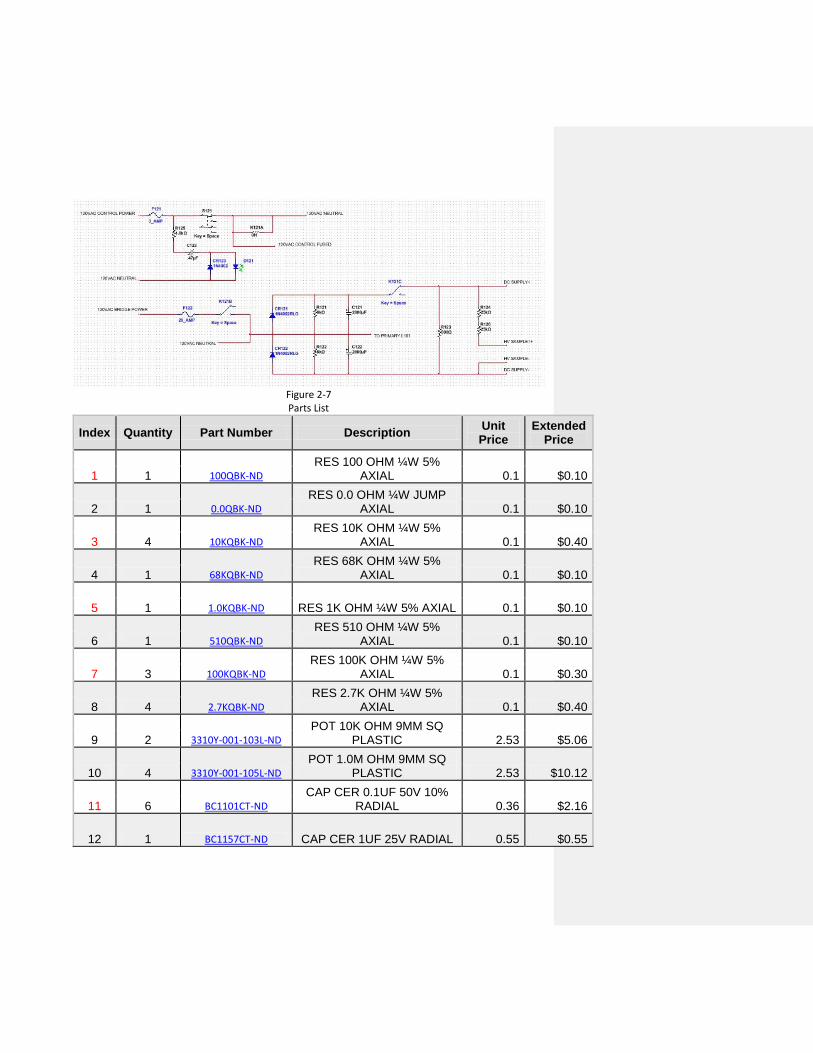
Figure 2-7 Parts List
Index Quantity Part Number Description Unit Price
Extended Price
1 1 100QBK-ND
RES 100 OHM ¼W 5% AXIAL 0.1 $0.10
2 1 0.0QBK-ND
RES 0.0 OHM ¼W JUMP AXIAL 0.1 $0.10
3 4 10KQBK-ND
RES 10K OHM ¼W 5% AXIAL 0.1 $0.40
4 1 68KQBK-ND
RES 68K OHM ¼W 5% AXIAL 0.1 $0.10
5 1 1.0KQBK-ND RES 1K OHM ¼W 5% AXIAL 0.1 $0.10
6 1 510QBK-ND
RES 510 OHM ¼W 5% AXIAL 0.1 $0.10
7 3 100KQBK-ND
RES 100K OHM ¼W 5% AXIAL 0.1 $0.30
8 4 2.7KQBK-ND
RES 2.7K OHM ¼W 5% AXIAL 0.1 $0.40
9 2 3310Y-001-103L-ND
POT 10K OHM 9MM SQ PLASTIC 2.53 $5.06
10 4 3310Y-001-105L-ND
POT 1.0M OHM 9MM SQ PLASTIC 2.53 $10.12
11 6 BC1101CT-ND
CAP CER 0.1UF 50V 10% RADIAL 0.36 $2.16
12 1 BC1157CT-ND CAP CER 1UF 25V RADIAL 0.55 $0.55

13 7 BC1095CT-ND
CAP CER 10000PF 50V 10% RADIAL 0.31 $2.17
14 2 BC1098CT-ND
CAP CER 0.033UF 50V 10% RADIAL 0.37 $0.74
15 1 399-3579-ND
CAP TANT 10UF 35V 10% RADIAL 1.84 $1.84
16 4 1N4002DICT-ND
DIODE GEN PURPOSE 100V 1A DO41 0.14 $0.56
17 3 350-1562-ND
LED 3MM BLUE WATER CLEAR 1.75 $5.25
18 5 LM555CNNS/NOPB-
ND
IC OSC MONO TIMING 8-DIP 1.11 $5.55
19 1 1295K-ND
HOLDER BATT 9V UNIVER PLASTIC QF 1.8 $1.80
20 3 EG1506-ND
SWITCH ROCKER DPST 8A 125V 1.61 $4.83
21 1 360-1945-ND
SWITCH PUSH SPDT 0.4VA 28V 8.63 $8.63
22 2 ARFX1064-ND
CONN BNC JACK STR 50 OHM SOLDER 1.77 $3.54
23 5 ED3108-ND
IC SOCKET 8PIN MS TIN/TIN .300 0.74 $3.70
24 6 226-2000-ND
KNOB CLR GLOSS.50”DIA .125”SHAFT 6.28 $37.68
25 1 560QBK-ND
RES 560 OHM ¼W 5% AXIAL 0.1 $0.10
26 1 15KQBK-ND
RES 15K OHM ¼W 5% AXIAL 0.1 $0.10
27 5 1.0KQBK-ND RES 1K OHM ¼W 5% AXIAL 0.1 $0.50
28 1 P1.6W-3BK-ND RES 1.6 OHM 3W 5% AXIAL 0.61 $0.61
29 2 3296W-103LF-ND
TRIMMER 10K OHM 0.5W PC PIN 2.31 $4.62
30 2 10KQBK-ND
RES 10K OHM ¼W 5% AXIAL 0.1 $0.20
31 2 100KQBK-ND
RES 100K OHM ¼W 5% AXIAL 0.1 $0.20
32 4 470QBK-ND RES 470 OHM ¼W 5% 0.1 $0.40
AXIAL
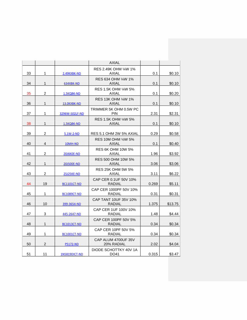
33 1 2.49KXBK-ND
RES 2.49K OHM ¼W 1% AXIAL 0.1 $0.10
34 1 634XBK-ND
RES 634 OHM ¼W 1% AXIAL 0.1 $0.10
35 2 1.5KQBK-ND
RES 1.5K OHM ¼W 5% AXIAL 0.1 $0.20
36 1 13.0KXBK-ND
RES 13K OHM ¼W 1% AXIAL 0.1 $0.10
37 1 3296W-502LF-ND
TRIMMER 5K OHM 0.5W PC PIN 2.31 $2.31
38 1 1.5KQBK-ND
RES 1.5K OHM ¼W 5% AXIAL 0.1 $0.10
39 2 5.1W-2-ND RES 5.1 OHM 2W 5% AXIAL 0.29 $0.58
40 4 10MH-ND
RES 10M OHM ½W 5% AXIAL 0.1 $0.40
41 2 20J6K0E-ND
RES 6K OHM 10W 5% AXIAL 1.96 $3.92
42 1 20J500E-ND
RES 500 OHM 10W 5% AXIAL 3.06 $3.06
43 2 25J25KE-ND
RES 25K OHM 5W 5% AXIAL 3.11 $6.22
44 19 BC1101CT-ND
CAP CER 0.1UF 50V 10% RADIAL 0.269 $5.11
45 1 BC1089CT-ND
CAP CER 1000PF 50V 10% RADIAL 0.31 $0.31
46 10 399-3654-ND
CAP TANT 10UF 35V 10% RADIAL 1.375 $13.75
47 3 445-2647-ND
CAP CER 1UF 100V 10% RADIAL 1.48 $4.44
48 1 BC1013CT-ND
CAP CER 100PF 50V 5% RADIAL 0.34 $0.34
49 1 BC1001CT-ND
CAP CER 10PF 50V 5% RADIAL 0.34 $0.34
50 2 P5172-ND
CAP ALUM 4700UF 35V 20% RADIAL 2.02 $4.04
51 11 1N5819DICT-ND
DIODE SCHOTTKY 40V 1A DO41 0.315 $3.47

52 2 1N5337BRLGOSCT-ND
DIODE ZENER 4.7V 5W AXIAL 0.54 $1.08
53 4 1N4148DICT-ND
DIODE SWITCHING 75V 0.15A DO35 0.12 $0.48
54 5 1N4002DICT-ND
DIODE GEN PURPOSE 100V 1A DO41 0.14 $0.70
55 2 VS-20ETS08FPPBF-ND
DIODE GP 800V 20A TO220ACFP 2.83 $5.66
56 1 1.5KE7V5CADICT-ND
TVS DIODE 6.4VWM 11.3VC DO201 0.77 $0.77
57 1 P6KE18CALFCT-ND
TVS DIODE 15.3VWM 25.2VC AXIAL 0.49 $0.49
58 4 1N4752ADICT-ND
DIODE ZENER 33V 1W DO41 0.43 $1.72
59 2 1.5KE33CADICT-ND
TVS DIODE 28.2VWM 45.7VC DO201 0.77 $1.54
60 4 5KP220CALFCT-ND
TVS DIODE 220VWM 371.1VC AXIAL 4.45 $17.80
61 1 296-1577-5-ND
IC HEX SCHMITT-TRIG INV 14-DIP 0.52 $0.52
62 1 296-1602-5-ND
IC D-TYPE POS TRG DUAL 14DIP 0.52 $0.52
63 1 296-1570-5-ND
IC QUAD 2-INPUT AND GATE 14-DIP 0.52 $0.52
64 1 296-13689-5-ND
IC MOSFET DRVR SGL HS 9A 8-DIP 3.02 $3.02
65 1 296-13686-5-ND
IC MOSFET DRVR SGL HS 9A 8-DIP 3.02 $3.02
66 2 LM311NNS/NOPB-ND
IC VOLTAGE COMPARATOR 8-DIP 0.91 $1.82
67 1 LM555CNNS/NOPB-
ND
IC OSC MONO TIMING 8-DIP 1.11 $1.11
68 1 LT1630CN8#PBF-ND
IC OPAMP GP 30MHZ RRO 8DIP 6.53 $6.53
69 1 LM3916N-1/NOPB-ND
IC DRIVER DOT BAR DISPLAY 18-DIP 2.64 $2.64
70 1 TLP372F-ND
OPTOCOUPLER DARL 5KVRMS 6DIP 0.91 $0.91
71 1 LM35DT-ND IC SENSOR PREC CENT 3.57 $3.57

TEMP TO220-3
72 1 LM340T-5.0/NOPB-
ND IC REG LDO 5V 1A TO220-3 1.66 $1.66
73 1 LM340T-15-ND
IC REG LDO 15V 1A TO220-3 1.77 $1.77
74 2 237-1096-ND
TRANSF 14MH CRNT SENSE 6.88 $13.76
75 2 MHB14K-ND
SHROUDED HEADER 14 POS STRAIGHT 2.65 $5.30
76 1 C3AAG-1406G-ND
IDC CABLE – CSC14G/AE14G/CSC14G 6.83 $6.83
77 13 7701K-ND
TERM W/ASSEMBLD SCREW VERT PCMNT 0.462 $6.01
78 11 ED1514-ND
TERMINAL BLOCK 3.5MM 2POS PCB 0.591 $6.50
79 1 ED1515-ND
TERMINAL BLOCK 3.5MM 3POS PCB 0.86 $0.86
80 7 ED3108-ND
IC SOCKET 8PIN MS TIN/TIN .300 0.74 $5.18
81 3 ED3114-ND
IC SOCKET 14PIN MS TIN/TIN .300 0.98 $2.94
82 1 ARFX1064-ND
CONN BNC JACK STR 50 OHM SOLDER 1.77 $1.77
83 4 345-1087-ND
HEATSINK LOW HEIGHT BLK TO-220 0.23 $0.92
84 1 100QBK-ND
RES 100 OHM ¼W 5% AXIAL 0.1 $0.10
Subtotal $259.42
Shipping Estimate
Sales Tax unknown

Progress Report: 3/17/2014 Parts We have received all of the parts needed for the Tesla Coil itself and are currently awaiting the parts for the Audio Modulator. Circuits We have the circuits for the Dual Resonate Solid State Tesla Coil (DRSSTC) nearly completed. The peak Current Feedback circuit, Synchronized Shutdown circuit, Primary Current Sensor, Peak Current Circuit, DC power supply charging indicator circuit, Low Voltage Power Supply Circuit, Half-Bridge Power Circuit, and Capacitor banks have been completed and can be seen below.
Figure 3-1: Circuits overview

Figure 3-2: Capacitor Bank

Enclosure and Structure Along with the circuit boards the base for the tesla coil has been constructed. The two layers are not yet fastened together though, this is because assembly needs to take place on both layers separately (primary and secondary, as well as circuit boards) and it is easier when the two halves are still separated. They will be fastened together when everything else is in place (see image below).The inner primary coil guide creates a mold to run the copper tube through and measures 8’’ in diameter with a .075’’ upward slope until six passes/rings are created while the upper most guides allow for a strike rail to be inserted at a height just above the primary coil and has a 12’’ diameter. The purpose of the strike rail is to prevent any discharges from the coil from striking the primary coil during operation. If this occurs, it would not be catastrophic, although it would produce very noisy input signals and overtime, reduce the life of the capacitors. Below you will find the pictures of our current progress on the base.
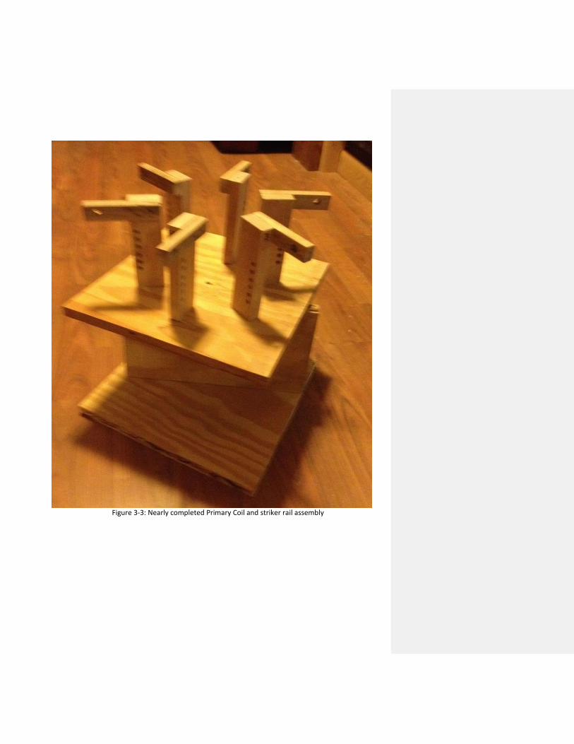
Figure 3-3: Nearly completed Primary Coil and striker rail assembly

Figure 3-4: Strike rail support for size comparison

Figure 3-5: Primary Coil base prior to strike rail
In Progress: The remaining parts of the structure, which are the Toroid, Secondary Coil, and circuit enclosures are still in the process of acquiring materials for, but should take very little time to construct. It takes some time to find nonconductive hardware for the Secondary Coil, so some of these delays were expected (we have some Nylon screws and nuts on order). External enclosures also are in the works, plans just need to be finalized and hardware (found at local stores) will need to be acquired. Testing: With the Primary and Secondary coil being incomplete, as well as the modulator, it is currently impossible to test functionality with any meaningful results. The only true result we have is we checked some of the major components for functionality and to ensure that no damage had been taken during the shipping process. Updated Deadlines: 3/17/14 Present: 2/20/14 Finish design troubleshoot and board circuit board creation: 3/2/14 Finish building structure and enclosures: 3/10/14 3/28/14 Finish building and troubleshooting individual circuits: 3/10/14 3/28/14 Finish integrating circuits and troubleshooting: 4/5/14