Embed Size (px)
Citation preview

UNCLASSIFIED
AD NUMBER
AD477479
NEW LIMITATION CHANGE
TOApproved for public release, distributionunlimited
FROMDistribution authorized to U.S. Gov't.agencies only; Administrative/OperationalUse; 27 Sep 1965. Other requests shall bereferred to Army Research and DevelopmentProcurement Office, For Belvoir, VA.
AUTHORITY
USAERDL ltr, 21 Jul 1966
THIS PAGE IS UNCLASSIFIED

/ Engineering Design Report
JTCIERMOELECTRIC ENVIRONMENTAL
CONTROL UNIT
For
II RESEARCH AND DEVELOPMENT PROCUREMENT OFFICE
U.S. ARMY ENGINEER RESEARCH AND DEVELOPMENT LABORATORIES
UFORT BELVOIR VIRGINIA
C-)
CONTRACT DA-44-009-AMC-1135(T)
TASK NO. ID 643303 D54503
I
1 !.I ) Air Conditioning Company
MILITARY EQUIPMENT DEPARTMENT
Bach transmittal of this document outside the agencies
of the U. S. overnment rn~ hini prior rproval of 1Comman~ding Officer, Arm~y Enginoor Rezearch & DeveloPllft
Labs, Port Bilvoir, Va. 22060 CU
USI WNTE S5'15 L
THE VIEWS AGENCYIONY THE.\?' - :~Ti GZC
'3Z BY T (
DZPARTMET 01 THE AM.
0-P,

~~ ,'ngineering Design Repait,
for
j THERMOELECTRIC ENVIRONMENTAL CONTROL UWJTT,
-Y9IA
Prepared for
I RESEARCH AND DEVELOPMENT PROCUREMENT OFFICE
U.S. ARMY ENGINEER RESEARCH AND DEVELOPMENT LABORATORIES
FORT BELVOIR, VIRGINIA
ft*A-44-9-AMC-1135 (T)
7WWW0*:D-643303 D54503
Submitted by
Military Equipment Department, Carrier Air Conditioning Company
I Syracuse, Now York
1 27 September 1985

TABLE OF CONTENTS
Paragraph Title Pagr-
1.0 INTRODUCTION................................... 1
1.1 General.........................................1
1. 2 Sstem Requirements............................1I
11.3 Proposed Work................................. 2
1.4 Summary of Work Completed....................... 2
2.0 SYSTEM ANALYSIS................................. 3
2.1 General...................................... 3
2. 2 Thermoelectric Coil............................. 3
2. 3 Air Handling System............................. 9
12.4 Control and Power Conversion System................ 11
3.0 SYSTEM DESIGN.................................. 12
3.1 Thermoelectric Coil............................. 12
13. 2 Control and Power Conversion...................... 15
3.3 Design Details................................. 16
3.4 Desip Drawings................................ 22
3.5 Electrical Circuit Diagram........................ 23
3.6 Desian R~equirement............................. 24
4.0 SYSTEM OPERA71ON............................ 25
4.1 Description of gperation.......................... 25
4.2 P~erUnix Procedure............................. 29
I4.3 9peraing Performance ................... 30
I5.0 MAINTE NANCE PROCEDURES.................... 41
5.1 Thermoelectric Module........................... 41
5.2 Internal fta....................... ........... 42

TABLE OF CONTENTS(continued) .
Paragraph Title Page
5.3 External Fan ................................. 42
5.4 Control and Power Conversion Package ............. 42
5.5 Frequency Changeover .......................... 43
6.0 MANUFACTURING PROCEDURE ...................... 43
7.0 COST ESTIMATE ...... ........................... 44
8.0 SUMMARY OF RESULTS ............................ 46
9.0 RECOMMENDATIONS 4"..........................4
APPENDIXA ................................ A-1
T
[i
APPENDIXB..................................... B-i
r
El
I.I
II UiI

1.0 INTRODUCTION
1.1 General
This report is submitted in fulfillment of contract DA-44-009-AMC-1135(T) dated
June 2, 1965. In accordance with the requirements of the contract, a detailed engineering
I design is provided for a 24,000 Btu/hr thermoelectric environmental control unit. The
design has been formulated to meet the system requirements described in Exhibit "A",
I Purchase Description of Request for Quotation No. 65-1816-B dated January 5, 1965 and
Amendment No. 1 dated April 26, 1965.
The design presented in this report is a practical one for the application. The analyt-
ical and design optimization techniques which are employed have been qualified by previous
experience in designing and building thermoelectric systems. Useful experience which
was utilized in this study includes thz design and development of a thermoelectric 'ir condi-
tioning system for submarines, performed under contracts NObs 77112 and 84598 for the
Pureau of Ships, U.S. Navy Department. More recently the first thermoelectric air condi-
tioning and control systems to be sold for a commercial application were developed by Carrier '
for Installation in the headquarters office building of S.C. Johnson and Son, Inc., Racine,
Wisconsin. Twenty-eight complete systems have been in operation for approximately one
year. The advantages and proven meth As which were utilized in these systems have been
incorporated into the environmental control unit design provided herein. The experience
gained in these and other similar developments provides assurance that an actual system of
the design shown can be built successfully and will perform in accordance with the operational
ch&,racteristics described. J
1. 2 System Requirements
IThe Purchase Description calls for a complete engineering design of a thermoelectric
environmental control unit to be optimized for minimum size and weight as well as for maxi-
mum efficiency. The design conditions for this system are detailed in the Purchase Descrip-
tion. A brief summary of the design conditions is listed in Table L:
II

TABLE I.
Cooling capacity ............... 24,000 Btu/hr
Ambient air temperature ......... 1200F
Supply air temperature .......... 92 0 F
Coefficient of performance ....... Minimum of 1. 0Heating capacity ............... Unspecified, consistent with full reversal of
design operating voltage
Maximum dimensions ........... 40 in. wide x 18 in. deep x 66 in. high
Maximum volume .............. 15 cubic feet
Supply air flow ................ 840 to 1,000
Supply air pressure ............. 0.25 in. of water
Control ..................... Provisions for both automatic and manualoperation
Power conversion .............. Solid state without voltage transformation
Main power supply ............. 208 volt, 3 phase, adaptable to both60 and 400 cps.
Reliability .................... Capable of continuous operating for10,000 hours
Maximum noise level ............ ASHRAE NC-60
1.3 Proposed Work
On February 5, 1965 Carrier Proposal No. MD8512-2 was submitted to USAERDL
in reply to the subject Proposal Request. This proposal detailed the work required to meet
the specifications of the Purchase Description. No exceptions were taken to these specifica-
tions. The proposed work included a complete system analysis in order to provide an optimum
design for the subject unit. This work has subsequently been completed as proposed; the
exact procedure followed and the results obtained are described in the following sections of
this report.
1.4 Summary of Work Completed jjIn order to formulate the system design, an extensive optimization analysis was
carried out. In this analysis, twelve design parameters were optimized for minimum weight
and maximum efficiency, four of which describe the TE panel configuration and eight which
describe the heat exchanger characteristics.
it2

Next, a study was made of the various system arrangements that could incorporate
the optimized T.E. coil into a practical design which would meet the requirements of the pur-
chase description. Consideration was also given to the type of fans which could be utilized
I with these various system arrangements. Similarly, various methods for controlling the
system were studied. From the results of these studies, a final system design was developed
as shown in Section 3. 0 of this report. Further calculations were then made to determine
the performance characteristics of this unit over a complete range of operating conditions.
Performance information is contained in Section 4. 3.
The system described in Section 3.0 is 28 inches wide by 18 inches deep by 63 inches
high, weighs approximately 380 pounds, operates at an overall coefficient of performance
(COP) of 1. 12, and has a net cooling capacity of 24,000 Btu/hr at design operating conditions.
The dual frequency vaneaxial f,-ns selected for the design are well suited to meet the reli-
ability and noise requirements. The power rectifier will furnish 3 phase, full wave d-c
power without voltage transformation. The contral system will furnish modulated capacity
control from full cooling to full heating as required by he system load.
2.0 SYSTEM ANALYSIS
2.1 General
In order to make a complete system analysis, the environmental control unit was
divided into three subsystems which, for convenience purposes, can be considered sep-
arately. These subsystems consist of the thermoelectric coil, the air handling system, and
the control and power conversion system. The thermoelectric coil and the air handlingsystem are very closely related physically. However, for purposes of design, the control
and power conversion system may be considered to be independent of the other subsystems
- so i" as physical interrelations are concerned. Some reasons for this include the small
size, light weight, and high efficiency of this subsystem. Also, because this portion of the
system is physically connected to the other parts by light flexible wire, it Is not restricted
in its physical location or orientation to the others.
2.2 Thermoelectric Coil
t There are 14 major physical and operating parameters that affect the size, weight,
and performance of an air-to-air thermoelectric unit. These are:
33

1. Element length
2. Element diameter
3. Element packing density (ratio of element area to panel area)
4. Conductor strap thickness
5. Operating current
6. Intcrnai fin spacing
7. External fin spacing
8. Internal fin thickness
9. External fin thickness
10. Internal fin height
11. External fin height
12. Fin material
13. Internal air velocity
14. External air velocity
Because the thermoelectric coil is the heaviest part of the system, it is of consid- -.
erable importance that this coil be optimized for minimum weight. The system fans also
represent a substantial portion of the overall weight, the size and power requirements of
which must also be included in this study in order to yield an optimum system. Fortunately,
some of the system parameters do not require optimization. For example, the fin material
must be aluminum, since it has the highest ratio of thermal conductivity to weight. Also,
from past experience, it is known that the optimum strap thickness is considerably less than
the minimum thickness that can be physically handled efficiently. The minimum conductor
strap thickness is considered to be 0.020 inches for this system.
2.2.1 System Optimization Procedure. In order to optimize the remaining 12 parameters,
equations were written which describe the system in terms of these parameters. These
equations were then programmed into an analog computer and solved while each parameter
was varied through a complete range of values. The results were then plotted to show var-
iation in system coefficient of performance over a range of operating current density and for
various values of the parameter being varied. An example of this plot is shown in Figure 1.
This curve illustrates the significance of parameter variation since it shows the large change ,
in performance that can be expected as a result of changes in internal air velocity. Not all
of the parameters have this much effect on system performance or weight. ii
4

Fcrtunately, the optimum value of each parameter is somewhat independent of the
others and; therefore, this proce, re converges on an optimum design quite rapidly. To
initiate this procedure, it was necessary to first assume a value for each parameter. Next,
Ifor each parameter, calculations were made over the complete range and the optimum param-
eter value was then used while the next parameter was varied. This procedure continued
until all parameters were optimized O"e first time, then the entire procedure was repeated a
second time to insure that all values represented the true optimum. Table II shows these
parameters in the order they were optimized, the initial assumed parameter value, the
parameter value after the first optimization, and the final value after the second optimization.
I TABLE II
ASSUMED VALUE VALUEINITIAL AFTER FIRST AFTER SECOND
PARAMETER VALUE OPTIMIZATION OPTIMIZATION
Packing density (%) -- 50 50Internal air velocity (ft/min.) 600 300 300External air velocity (ft/min.) 1000 800 700
Internal fin spacing (fin/in.) 24 28 30
External fin spacing (fin/in.) 24 28 30
I Internal fin thickness (in.) 0.010 0. 007 0. 006
External fin thickness (in.) 0.010 0.007 0. 006
I Internal fin height (in.) 1.00 0.80 0.80
External fin height (in.) 1.00 1.00 1.00
I Some of the thermoelectric panel parameters are not shown In Table I. The ele-
ment length is not included because this value was set up as a variable on the computer
program and was varied to give the maximum coefficient of performance for each calcula-
tion (the element length was optimized for each solution). The other parameters not shown
1 are element diameter and operating current. Indirectly. these values are combined into the
current density and show up as one of the variables on the optimlzation curve, Figure 1.
The element diameter is not actually optimized until the system design is finalized. Figure
2 shows the final results of this optimization procedure. Thic curve shows tm optimum
relation between system weight and system performance over the practical range of opera-
ting current density.
I5I4
.I
I ,

1.4 3INTERNAL AIR VELOCITY
300 FT/MIN3
1.3 400 FT /MIN
500 FT/MIN
21.21
o 600 FT/MINI- 15 AMPS
U.U. IS AMPSw
(0
U)
0.9 P.5 AMPSOPERATING CURRENT DENSITYAMPS/ 7 MILLIMETER COUPLE
0.8 1too 300 400 500
SYSTEM WEIGHTLB
Figure 1. Optimization Curve Showing Weight and Performance over aRangt. of Internal Air Velocity
8

OPERATING CURRENT DENSITY
I1.5 AMPS/ 7 MILLIMETER COUPLE15
S1.4
I IsU-
1 2.1
w1.20
0
1.01 I3100 200 300 400
SYSTEM WEIGHT, LB
Figure 2. Final Optimization Curve showing System Weight andPerformance as a Function of Current Density

It should be pointed out that in this study, reference is always made to overall
system weight and system performance, not thermoelectric coil weight or performance.
System weight includes the weight of the thermoelectric coil, the weight of the fans (which
is calculated as a function of the fan power requirement) and the weight of the unit frame and
manifolds which are assumed to equal 50 per cent of the fan and coil weight. System coeffi-
cient of performance is defined as the system cooling capacity divided by system power
required. System power required includes fan power as well as the power required by the
thermoelectric coil. Fan power is calculated from fin pressure drop and air velocity based
on an overall fan-motor efficiency of 40 per cent. System cooling capacity is always equal Vto 24,000 Btu/hr, but is calculated by subtracting the internal fan power from the thermo-
electric coil cooling capacity. I2.2.2. Analog Procedure. The optimization equations and the analog procedure used to
solve these equations are essentially the same as those described in detail in Carrier's VProposal No. MD-8512-2. The exact equations and calculations are presented in the orig-
inal design calculations attached to Copy No. 1 of thiis report.
2.2.3 Material Parameters. Thermoelectric material parameters used in this study are
also the same as described in the reference proposal. These parameters represent average
values obtained from actual measurement during fabrication of more than 600 thermoelectric
panels built by Carrier, and are based on currently available commercial thermoelectric
material. Table III shows the variation in material parameters with temperature.
TABLE III INUMERICAL VALUE 1
PARAMETER SYMBOL UNITS AT 81OF AT 152 0 F
Seebeck coefficient a Volts/couple -OF 1. 98 x 154 2.18 x 10'
Electrical resistivity Pn+Pp Ohm-in. /couple 7.84 x 164 9. 37 x 1-04
Thermal conductivity k Btu-in. /hr-ft a- F 7.72 7.84
Figure of merit Z OC 2.86 x IF" 2.86 x 1ia
Electrical resistance of Ohm-cm2 1 x 1 1 x I'TE junctions r
Thermal conductivity of Btu-in. /hr-ft2 -?F 0. 20 0. 20 Ifoam insulation kins
I* 8
I

Although these parameter values do vary with temperature, they were consideredconstant at the 152 0F value for the optimization calculations. This is justified because the
figure of merit is directly related to efficiency and this parameter does not vary with tem-
Iperature over this range. It is important to note, however, that these variations are taken
into account in the final design and the performance calculations described in Section 3. 0 and
I Section 4.3.
The heat exchanger surfaces utilized in this analysis are a straight fin laminar flow
I type. The performance characteristics of these surfaces may be found in the original design
calculations section.
2.3 Air Handling System
I Optimization of the air handling system was accomplished to the greatest extent
possible as described in paragraph 2.2. 1. Other aspects of this subsystem which were
further analyzed include fan efficiency, fan type, system noise level, and air manifold
arrangement.
Fan efficiency has a definite relationship to fan type. If dual fans (two fans opera-
ting in parallel flow) are used for both the internal and external air streams, these fans
would operate at specific speeds of 82,500 and 88,000 respectively:
= rm (~ 1/2 3/4[specific speed = (rpm) (cfm)/ (inch water pressure)3 4
These specific speed ranges represent an efficient operating condition for vaneaxial type
fans. If it were desirable to use forward-curved, squirrel-cage type blowers; two double-
inlet scrolls or four single-inlet units should be used. It was estimated that the overall fan-
motor efficiency of the vaneaxial units would be twice that of the squirrel-cage units. Other
itype blowers available were not considered to be feasible for this system.
In order to meet the dual frequency requirement, it is necessary that fan motors
operate at both 60 and 400 cps. Dual frequency motors are available with separate windings
within the same motor frame. Also, statically co;nmutated motors have recently beendeveloped which will operate on either frequoncy; however, information obtained from the
I manufacturers indicate that these motors are not sufficiently developed to be considered at
this time. Thus, it appears that the dual frequency motors are best suited for this applica-
tion. With these motors, it will be necessary to connect the power to the proper winding rterminals depending on the power supply frequency.
I9I

IWith respect to system noise level, it appears that the NC-60 requirement could be
met using either type of blower considered. Typically a squirrel-cage blower will generate
the greatest noise in the low octave bands where the human ear is less sensitive. Although
the vaneaxial fan generates the highest noise levels in the center octave bands, this noise is
more readily attenuated with acoustical insulation. In this system, one inch thick fiberglass
insulation will be used wherever it will effectively absorb sound or decrease thermal conduc-
tion losses. iProbably the most important consideration related to the air handling system is the
manifold arrangement. This, in conjunction with the type and number of fans used, largely idictates the size and shape of the overall unit. The possibility exists that the manifolds
could be eliminated by going to a cross-flow coil design; however, this presents other prob-
lems. In a crossflow design, the coil must be shallow in two directions in order to keep the
fan pressure requirements at a reasonable level. Making the coil shallow in two directions
on a system of this size results in a long thin coil which is difficult to design into a system.
A counterflow coil, being shallow in only one direction, does not have this limitation.
In order to obtain a good manifold arrangement, five possible systems were sketched
out and the advantages and disadvantages of each were considered. Systems 1, 2, and 3
were relatively short and wide. A combination of squirrel-cage and vaneaxial fans were used
in System 1. System 2 was similar except that it used only vaneaxial fans. System 3 used
vaneaxial fans in a somewhat different arrangement than System 2. The major disadvantages I,'of all three systems was large size and poor fan and manifold air entrance arrangements.
System 4 was a relatively high and narrow arrangement using all vaneaxial fans. This sys-
tem was smaller and had considerably better air flow arrangements than the other three
systems. From this arrangement it became obvious that System 4 could be made shorter by jincreasing the coil depth slightly. System 5 includes this change which saved 12 per cent
in system volume and 20 per cent in manifold length. The penalty for this saving was a 20 jper cent increase in fan power resulting in a three and one-half per cent decrease in system
coefficient of performance.
System 5 was then selected as the best fan and manifold arrangement to be incor-
porated into the final design. The advantages of this system arrangement are pointed out in
Section 3.0 of this report.
IiIi
10
Ii

2.4 Control and Power Conversion System
The object of the control and power conversion system is to regulate d-c power to
the thermoelectric coil in response to a signal obtained from the temperature sensor. In
order to provide this power regulation, two step-control methods and five proportional-
control methods were considered. The criteria used to evaluate these methods were size,
j efficiency, reliability, degree of modulation, and cost.
The first method considered was a switching scheme whereby the total current
fthrough the thermoelectric coil could be increased in discrete steps by automatically recon-
necting the thermoelectric modules from a series to a parallel circuit. The main objection
j. to this method is the increased cost of the coil, since a proportionately larger number of
smaller couples would be required if the unit were to operate at full capacity with the
jmodules connected in parallel. Transforming the power to a lower voltage would solve the
problem mentioned above, but this could be accomplished only at the expense of transformer
weight and power loss. In addition, the specifications stated that power conversion should
1. be accomplished without voltage transformation.
A simple two-step control was considered whereby the voltage to the coil would be
increased by switching from half-wave to full-wave rectification. The limited degree of
modulation attainable, which in turn affects the system efficiency, is the main dis..dvantage
ij of this method. Also, a special power generator would be necessary in order to operate on
half-wave power.
The five types of proportional control systems that were considered include:
(1) motor-generator set; (2) magnetic amplifier and rectifier; (3) servo-driven variable
transformer; (4) thyratron bridge; (5) silicon controlled rectifier bridge. SCR's and
thyratrons can be used in circuits other than the bridge circuits to accomplish proportional
I power conversion; however, the bridge circuit is more efficient and requires fewer power
components.
j The SCR bridge control method is easily the best of those considered above. The
reasons for this largely involve the small size, high efficiency, and low cost of this system.
Reliability information on SCR systems is incomplete at this time, but experience to date
indicates this method is at least as reliable as any of the other methods considered. On this
basis, the SCR full-wave bridge method was used in the final system design.
L
iiI
i1

3.0 SYSTEM DESIGN
3.1 Thermoelectric Coil
The final design of the thermoelectric environmental control unit was largely dic-
tated by the results obtained from the system analysis. However, in order to make this
design realistic, experience and engineering knowledge require that numerical values
obtained from the computer study be somewhat compromised.
It has been well substantiated that there are cooling capacity losses in this type
system that are very difficult to calculate. This includes such losses as air leakage, joule
heating in electrical wires and connectors, structural heat conduction, ductwork and mani-
fold conduction, thermoelectric material parameter variation, and non-uniform air flow
distribution. Added together, these losses equal nearly ten per cent of the system cooling --
capacity. Consequently, for a net capacity of 24,000 Btu/hr, the system should actually bedesigned for a capacity of 26,400 Btu/hr. Figure 3 shows the relationship between system 7weight and system performance when this ten per cent loss factor is included.
As mentioned in paragraph 2. 2. 1, the relationship between operating current andelement diameter must be such that the system will operate at 278 volts. A graphical method
shown in Figure 4 was used to determine this relationship. As shown on this graph, a single
line represents the relationship between operating current, d-c power and voltage (design
voltage = 278 volts d-c). The diagonal lines which cross the voltage line represent the rela-
tionship between current and power for systems made up of various diameter elements. The
vertical lines show the approximate relationship between system coefficient of performance
and d-c power draw. Thus, a system COP of 1.20 may be obtained by using 7.3 millimeter -r
diameter elements and the system should operate at 18. 0 amperes.
More exact calculations of the system performance later determined that the element
diameter should be 6.9 mm. and the system should operate at 17. 5 amperes. Reasons for
this deviation from the optimum result include:
(1) Thermoelectric material parameters were considered to be -
independent of temperature for the optimization calculations.
(2) Changes in coil depth and air flow velocities were made in
order to compact the system as described in paragraph 2.2.
12
II

K
III 1.4-
IOPERATING CURRENT DENSITY
S1.3 AMPS/7 MILLIMETER COUPLE0U. 15
.18a.
0 "1 a
I--
I.0
I o 2
I I0.9100 200 300 400
SYSTEM WEIGHT, LB
* I Figure 3. Design Curve Showing System Weight and Perforr inoe
when 10 Per Cen. Capacity Losses are Included
SI13

ELEMENT DIA, MILLIMETERS
7.47. 3
7.0 I
20 1DESIGN POINT 18.0 AMPS
7.3 MILLIMETER DiA.I
w
5 -SSTEM VOLTAGE. 278 VOLTS OC
02 ITHERMOELECTRIC POWER DRAW, KILLOWATTSI
Figure 4. Graphical Determination of ThermoelectricjElement Diameter
141

i3.2 Control and Power Conversion
Although the system analysis determined that an SCR full-wave bridge would provide
the best means of supplying power to the thermoelectric coil, a number of considerations
must be taken into account before the exact control and power conversions circuit is finalized.
The power conversion is accomplished with a 3-phase bridge capable of supplying approxi-
Imately six kilowatts of d-c power when operated from a 208 volt, 60 or 400 cycle supply.
After full-wave rectification and allowing for a 2. 5 volt drop across the SCRts, the 208 volt
a-c supply converts to 278 volts d-c. The magnitude of the d-c voltage can be controlled by
controlling the conduction time of the SCR's. Thus, the main problem was to design the
necessary circuitry to control the SCR conduction time in proportion to the deviation from
the system set point temperature. Also, the polarity of the output voltage must be reversed
as the heat pumping requirement changes from heating to cooling and vice versa. Additional
circuitry must be designed for manual operation as well as for over-temperature protection.
Automatic reversing could be accomplished statically by using 12 SCRts in the
bridge, or by using a double pole, double throw relay in conjunction with a bridge containing
three SCR's and three diodes. The relay method was used because of its simplicity.
The control circuitry includes a firing circuit, a signal shaping network, an
amplifier, a temperature sensor and a Schmitt trigger. The Schmitt trigger is used to con-
vert the analog signal from the temperature sensor to a digital signal for operating the
reversing relay.
The temperature sensor consists of a thermistor connected in a d-c bridge. The
voltage signal from the bridge is proportional to the resistance o the utormistor. The
amplifier is required to increase this signal to a workable level.
The signal shaping network is required to provide a dead zone about the set point
temperature and also to provide a 180 degree phase shift in the amplifier voltage signal when
Icooling is required.
The firing circuit controls the conduction time of the SCR's. The SCR's are non-
conducting until voltage pulses from the firing circuit are supplied to the SCR gates, at
which time conduction begins and continues until the end of a cycle.
Transistors and other semiconducter devices used in this .,Ircuit have character-
3 istics which vary with temperature. Therefore, the circuit is temperature compensated so
that temperature change of the control components will not affect the operation of the unit.
:I

A diode bypass of the SCR's is used for manual operation. A relay connects three
diodes into the bridge in place of the three SCR's. All of the automatic circuitry is bypassed
and maximum power will be supplied to the heat pump.
A thermistor over-temperature protection network was designed to protect the
thermoelectric modules from excessively high temperatures that might result from a fan
failure. If a thermistor detects a high temperature condition, power to the thermoelectric
modules is removed.
A radio frequency filter was designed and is used in the system for suppression of
interference which will be introduced by the switching of the SCR's.
The use of a filter for reducing the ripple at low output voltage was studied. The
results of the study indicated that the filter was not worth the extra weight it would add to
the system.
3.3 Design Details
The physical system configuration and the design system performance are outlined
below:
3. 3.1 Physical Configuration
a. Thermoelectric Panels
Element length, 0. 087 inch
Element diameter, 6. 9 mm.
Element packing density, 0.45
Conductor strap thickness, 0. 020 inch
Number of couples, 34 per panel
Panel size, 3.625 x 2. 540 x 0. 177 inches
b. Heat Exchangers
Parameter Internal HX External HX
Fin spacing, fin/inch 30 30
Fin material Aluminum Aluminum
Fin thickness, inch 0.006 0.006Fin height, inch 0.80 1.00
Size, inches 5. 25 x 7.37 x 0. 34 5.25 x 7.37 x 1.04 4
Ii

c. Thermoelectric Modules
Number of TE panels per module 4Number of TE couples per module 136
Number of heat exchanges per module 1 internal, 1 external
Size 5. 25 x 7. 37 x 2. 06 inches
IWeight 2.67 lb
d. Fans
I Parameter Internal External
Manufacturer General Dynamics General Dynamics
I Type Vaneaxial Vaneaxial
Identification Proposal No. RA-5519 Proposal No. RA-5520
Model No. 9071-A 9092-A
Length, inches 7-1/4 10-1/8
Diameter, inches 8-3/4 11
Weight, lb 13-1/2 28
e. Control and Monitor Panel
Size 14 x 13 x 4 inches
Weight 5 lb
I f. Control and Power Conversion Package
Size 20 x 8 x 4 inches
Weight 16 lb
g. Complete Thermoelectric System (24,000 Btu/hr)
Number of TE modules 60
Number of TE panels 240
I Number of TE couples 8160
Number of internal fans 2
I Number of external fans 2
Overall size 18 in. deop x 28 In. wide x 63 in. high
Overall volume 18.4 cubic feet
Overall weight 380 lb
I
I}1 1?
I2

3.3.2 System Performance (Design Point Operation)
a. Thermoelectric Coil
Main PowerSupply Frequency
60 cps 400 cps
Current, amperes d-c 17.5 17.7
Voltage, volts d-c 278 278
Power draw, kilowatts 4.86 4. 92
Cooling capacity, Btu/hr 28,050 28,230 ICoefficient of performance 1.69 1.68
Internal air velocity, ft/min 359 402
External air velocity, ft/min 838 945
b. Internal Fan, Each Unit I
60 cps 400 cps
Voltage, volts a-c 208 208 1Phase 3 3
Current, amperes a-c 0.6 1.5 1Power factor 0.85 0.51
Motor ef^-ciency 0.65 0.57
Brake horsepower, hp 0.16 0.21
Power draw, watts 184 275
Sound pressure level, C-scale 70 70 4Guaranteed life, hr 3,000 3,000
Expected life, hr 20,000 20,000
Air flow, cfm 510 560
Air pressure, in. of water 1.26 1.43
i8

Ic. External Fans, Each Unit
Main PowerSupply Frequency
60 cps 400 cps
Voltage, volts a-c 208 208
I Phase 3 3
Current, amperes a-c 2.4 5.3
Power factor 0.90 0.57
Motor efficiency 0.70 0.63
Brake hcrsepower, hp 0.73 0.92
Power draw, watts 780 1090
Sound pressure level, C-scale 80 80
I Guaranteed life, hr 3,000 3,000
Expected life, hr 20,000 20,000
Air flow, cfm 1260 1380
Air pressure, in. of water 1.75 2.00
I d. Complete System
60 cps 400 cps
Voltage, volts a-c 208 208
Current, amperes a-c 19.7 24.4
I Power factor 0.99 0.89
Phase 3 3Power draw, kilowatts 6.84 7.70
I Cooling capacity, Btu/hr 26,230 25,800
Overall coefficient of 1.12 0.98performance
Performance curves for the internal and external fans are shown in Figures 5 and
6, respectively. These graphs also show the system characteristic curves.
1
?. 5 .19
SI

0O.4'U
.Q3
90
GENERAL DYNAMICS/ EL ECTRO DYNA~IWCMODEL - 9 07 IA
1DENSITY
0 75 LS8/ FT3SPEED AS INDICATED
SYSTEMWCHARACTERISTIC;I
3700 RPM (400N)
3450 RPMj (SON~)
9 0. 4
0 AOR FLOW CFM 600flo
20

1.0
R 3750 RPM (400N)
x 3450 RPM (60N)
0.6-
V - GENERAL DYNAMICS/ ELEOTRO DYNAMIC
3.0
I 4 CHARACTERISTIC
0
600 B00 1000 1200 1400 1600I Al RFLOWsOFM
Figure S. Wxtna1 Fan Performance
1 21

3.4 Design Drawings
Detailed engineering drawings are included in Appendix A. Most of these are
assembly drawings, and the appropriate bill of material for each assembly is shown on the
drawing. Exact design details for all special components which are pertinent to the opera-
tion of the system are also shown on these drawings.
Drawing number R-1058-3429 shows a thermoelectric panel assembly. In opera-
tion, the electrical current will feed into the panel through one of the insulated lead straps Ithen aiternately through the n-type and p-type bismuth telluride elements and out the insu-
lated lead strap at the opposite end of the panel. The 34 pairs of elements in each panel are
connected in series by means of the 67 insulated conductor straps. The insulated conductor iistraps are made of a metalized ceramic wafer soldered between a copper conductor strap,
and a copper spacer. This sandwich assembly has a dielectric breakdown strength in excess
of 4000 volts d-c, and an electrical resistivity in excess of 101 2 ohms.
Drawing number R-1058-4430 shows how four of the thermoelectric panels are
soldered in place between the aluminum internal and external air heat exchangers to form a
module assembly. This module assembly is the basic building block of the thermoelectric
coil. In the complete system, 60 of these modules are stacked in 12 side-by-side banks,
each bank five modules high. The current flows through two panels on one side of each
module in series, then on through the two panels on the same side of the next module located
directly above the first, and so on through the five modules in one bank to the top of the
bank. At the top, current flows through a jumper strap to the panel located on the opposite Iside of the top module and then back down through the same five modules. At the bottom of
each bank the curiat will flow to the next bank of modules and so on in series through all
12 banks.
Drawing R-1058-9434 shows the unit framework assembly. The frame is constructed Ifrom 1-1/2 x 1-1/2 x 3/16 inch aluminum angle and 1-1/2 x 1-1/2 x 1/8 inch square aluminum
tubing welded together. Calculations determined that this size angle would keep the natural
frequency of the long structural members well above the rotational frequency of the system
fans. Item 26 of this drawing is the internal air supply manifold. These manifolds, as well
as the return manifolds, are formed from aluminum sheets insulated with a 3/16 Inch layer
of free foamed epoxy prior to cutting and frming.
22
bi !
It

Drawing R-1058-9431 shows the system control and monitor panel. This panel
mounts into a sealed, recessed compartment on the inside face of the unit such that it may,
if desired, be remotely located without resealing the opening from which it was removed.
Electrically, this panel is connected to the unit by a single feed-through connector mounted
near the bottom of the recessed compartment wall. The system temperature sensor mounted
f on the face of this panel is detailed on drawing R-1058-3432.
Drawing R-1058-9433 shows the power conversion and control package. This pack-
age is made up of a two-compartment box designed to confine radio frequency noise
generated by the silicon control rectifiers. The free convection fins mounted to the outside
of this box are designed to conduct heat away from the power rectifier which is mounted
$ directly adjacent to the fins on the inside of the box. The rectifier mounting blocks are in
good thermal contact with the aluminum box, but are electrically insulated from the box by
18 electrically insulated ceramic conductor straps.
Drawing R-1058-4435 shows the access cover assembly. This removable cover
mounts on the outside face of the unit and is easily removed to allow access to the
thermoelectric modules, the internal and external fans and the power rectifier and control
package. A fine mesh wire screen prevents dust and dirt from entering the external air
inlet, and the outer grill protects the unit from damage. The internal air return manifolds
.1iare mounted to the cover such that when the cover is tightened down, it will hold the thermo-
electric modules firmly in position.
Drawing R-1058-9436 shows six views of the complete environmental control unit
along with a sectional side elevation. This drawing shows the mounted location of all the
system components described above. The buss-bar which carries the electrical current
from one bank of modules to the next is detailed in drawing R-1058-3437.
: ! iDrawing R-1058-9439 shows a pictorial side elevation of the unit indicating the
flow paths of the internal and external air streams.
I I 3.5 Electrical Circuit Diagram
I Drawing R-1058-4428 shows the schematic wiring diagram for the system. As
shown, the 3-phase, 208 volt, 60 or 400 cycle power feeds into the unit through the main
power circuit breaker switch (CB1), through the power rectifier, through the reversing
relay (RR), and to the thermoelectric heat pump. Lead wires connect the module selector
switch to each of the 12 banks of thermoelectric modules so that the voltage drop across
*| each individual module bank, or across tho total coil, may be monitored on the voltmeter (VM).
23

The same input power feeds through the fan power circuit breaker (CB2) to the internal and
external fans, as well as to the control system voltage transformer (TRANS, 1). The auto-
matic control ni_'work is made up of a temperature sensor circuit, amplifier, Schmitt
trigger, signal shaping circuit, and firing circuit. This network picks up a signal from the
temperature sensor thermistor (TH1) and feeds a control signal through the pulse trans-
formers (PT1, PT2, PT3) to the gates of the silicon control rectifiers (SCRI, SCR2, SCR3).
At the same time, the Schmitt trigger controls the operation of the control relay (CR1) which
in turn operates the reversing relay (RR). The system selector switch (SWl) bypasses the
automatic control network when it is in the manual heat or manual cool position. In the
manual position, the reversing relay and the power rectifier circuit are controlled such that
the unit may operate at either full cooling or full heating. During manual operation, the
power to the thermoelectric coil bypasses the SCR's and is supplied through the power diodes
(D4, D5, D6). The over-temperature protection circuit monitors the signal from the over-
temperature thermistors (TH2, TH3, TH4, TH5), and will cut off the power to the rectifiers
by operating the control relay (CR2) which in turn will open the main contactor (MC). The
over-temperature thermistors are mounted to the thermoelectric coil frame so that they are
in good thermal contact with the internal and external air fins.
3. 6 Design Requirements
The design requirements for this system are specified in Section 2 of the Purchase
Description as amended by Amendment No. 1. The system design described in Sections 3.2,
3.3, and. 3.4 above meets or exceeds all of the specified requirements with the exception of
unit volume. The 18.4 cubic foot volume of this design exceeds the 15 cubic foot requirement
described in Section 2.2.3 of the Purchase Description. IWith regard to certain requirements describing the method of control, variations
are made in the exact method specified. However, the same end result is accomplished by
means that are considered better than those described. These variations are described
below; the section numbers listed refer to those used in the Purchase Description.
Section 2.4.2.2 - Automatic Capacity Control:
With this system design, automatic capacity control is accomplished by
modulating the voltage applied to the thermoelectric coil. This modula-
tion is continually proportional from full cooling to full heating. T7he
operation of this control system is described in more detail in Section
4. 1. 3.3 of this report.
24
, [i

Section 2.4. 3. 1 - Selector Switch:
IThe selector switch has only three positions: MANUAL HEAT,",
MANUAL COOL, and AUTOMATIC.
Section 2.4.3.1.3 - Off:
Power to the thermoelectric coil is turned off by turning the main
power circuit breaker switch to the OFF position,
Section 2.4. 3. 1. 5 - Start:
A special start mode of operation is not provided. With the fast
response time and the high heat pumping capacity of a thermo-electric unit during start-up, it appears that a special startingmode of operation should not be required.
.1 Section 2.4. 3. 2. 1 - Inside Fan Motor Switch:
The inside fan will run whenever the fan power circuit breaker
switch is on.
Section 2. 4. 3. 2. 2 - Outside Fan Motor Switch:
The outside fan motor switch has two positions, ON and AUTOMATIC.
The system could possibly be damaged if the external fans were
turned off when the unit was operating in the cooling mode, consequently
the OFF position was eliminated.
Section 2.4.3.5 - Montor Lights:1 A voltmeter and a thermoelectric module selector switch are located
on the control and monitor panel. This provides a means of checking
the exact voltage drop across each module bank.
Section 2.4. 7 - Thermoelectric Modules:This unit has 12 module banks each comprised of five identical modules.
4.0 SYSTEM OPERATION
I 4.1 Description of OpeQation
4.1.1 General. The basic subsystems comprising the thermoelectric environmental con-
Itrol unit are: (1) thermoelectric coil, (2) air handling, and (3) control and power conversion.
I1 25

Referring to Drawing R-1058-9439, the air flow paths through the fans, manifolds,
and thermoelectric coil are showa. Internal air enters the top of the unit just above the
internal fans and passes through the fans into the internal air supply manifolds. It then
passes through the thermoelectric coil, up through the six return air manifolds and leaves
the unit through the top opening near the outside face of the unit.
External air enters through the outside face of the unit, passes through the protective
grill and fine mesh screen straight into the external air fins of the thermoelectric coil.
After leaving the coil, air passes downward into the external fans and is discharged through
a protective grill near the bottom of the outside face. Thus, the two air streams pass -
through the coil in counter flow. The internal circuit is under positive pressure and the
external circuit under negative pressure so that any air leakage will always be from the
internal to the external air stream. 1The direction of heat flow through the thermoelectric modules is dependent on the
polarity of d-c power supplied to the modules. In the cooling mode, heat is pumped from ithe internal air stream to the external air stream. In the heating mode, heat is not
actually extracted from the external air stream, since the external fans are always off.
However, the heat equivalent of the power input is rejected to the internal air stream. Con-
trol of the d-c current flow quantity and direction is described in Section 4. 1. 2.
4.1.2 Control and Power Conversion
4. 1. 2. 1 Manual Operation. IRefer to Drawing R-1058-4428. When the system selector switch (SW1) is
in the manual cool position, the manual relay (MAN) is energized, the SCR's (SCRI, SCR2, ]
SCR3) are disconnected from the rectifier bridge, and the diodes (D4, D5, D6) are connected
to the bridge. The reversing relay (RR) is in the non-energized cooling position and 278 volts
d-c is applied to the thermoelectric heat pump.
With the system selector switch in the manual heat position, manual relay f(MAN) is again energized, the reversing relay (RR) is energized to the heating position, and
278 volts d-c is applied to the thermoelectric coil. Also, the fan relay (FR) is energized, icutting the external fans off.
I2
26
11

4.1.2.2 Automatic Operation.
In te automatic mode of operation, a small voltage signal is produced by
the temperature sensor in proportion to the difference between the set point temperature
and the temperature of the control thermistor (TH1). The resistance of the thermistor
decreases as the temperature increases, and this causes the voltage at the base of
transistor TR1 to increase in proportion to the temperature increase. The voltage signal
is amplified by transistor TR2 and then supplied to the reversing network consisting of a
i Schmitt trigger, a control relay (CR1), and the reversing relay (RR). Simultaneously, this
amplified signal is supplied to the signal shaping network.
I The amplifier and Schmitt trigger are biased so that the reversing occurs
at a set point temperature of 67 0F. As the temperature rises above 67 0 F, the control relay
i (CR1) is energized, opening its normally closed contacts. Also, the reversing relay is
de-energized placing a cooling polarity on the thermoelectric coil, and the fan relay (FR) is
de-energized turning on the external fans. As the temperature of the control thermistor
drops below 67 0F, the control relay (CR1) is de-energized which in turn energizes the
reversing relay to the heating position, and the fan relay turns off the external fans.g The signal shaping network provides a dead zone of * 50F about the set
point temperature. When the control thermistor temperature is in this dead zone, no signal
in supplied to the firing circuit, and consequently power is not supplied to the thermoelectric
col. As the control thermistor temperature increases above 720F, the voltage from the
S[sigial shaping network increases continuously until the full cooling signal is produced at
77 0 F. Conversely, as temperature drops below 62°F, the voltage decreases until the full
heating signal is produced at 57 0 F.
The voltage from the signal shaping network is supplied to the firingI[ circuit which controls the conduction time of the SCR's in proportion to the voltage signal.
Controlling the conduction time of the SCR's in turn controls the voltage applied to the
~ [ thermoelectric coil. Figure 7 shown the relation between the control thermistor temperatureand the applied system voltage. The firing circuit used bore is a unijunction type. In this
circuit, a voltage signal is converted to a time signal by charging a capacitor. Thus, aK ' high signal voltage corresponds to a short charging time which In turn results in a long
1 t
K. 12?

300
EXTERNAL FAN OFF EXTERNAL FAN ON
200
nOo HEATING COOlING
0-
1200 [
too-W
300 . I I ... .55 59 63 6? ?I 5 79
CON MOL THERMISTOR TWEKRATURE Ii
-u I

I4. 1. 2. 3 Over-Temperature Protection.
In the over-temperature protection circuit, the thermistors (TH2, TH3,
TH4, TH5) are located to protect the system against over-temperature conditions which
could be caused by an inoperative fan or by a blocked air passage. If the temperature of any
one of these thermistors exceeds 160OF durirg operation, then control relay (CR2) is
energized, which in turn de-energizes the main contactor (MC) removing power from the
thermoelectric coil. Simultaneously, the reset warning light on the control panel will go on
indicating an over-temperature condition has occurred. To resume operation after an
over-temperature condition occurs, the "reset" button must be depressed.
4.2 Operating Procedure
4.2.1 Automatic Operation. To operate this unit in the automatic mode, the following
sequential procedure should be followed:
1. Selector switch ... AUTO
2. External fan ...... AUTO
3. Fan power ....... ON
4. Main power ...... ON
Both the main power and the fan ?ower indicator lights should be on. The reset
light should be out; however, if the reset light is on immediately after the fan power switch
is turned on, then the reset button should be pushed.
If during automatic operation, or any mode of operation, the operator wants to
check the module operation, the voltage drop across anj of the 12 module banks may be
monitored by setting the module selector switch to the proper module bank number and
reading the voltage drop from the meoe&.
To turn the unit of when operating in the automatic mode, the sequence is:
1. Main power ...... OFF
2. Fan power ....... OF
14. . 2 Maual Operation. To operate the unit in either the manual cooling or tie manual
heating mode:1. Selector switch .... MAN. COOL OR MAN. HEAT
2. External fin ...... AUTO
,.3. Fanpower....... ON4. Main power ...... ON
29

To tur off unit:
1. Main power ...... OFF
2. Fan power ....... OFF
4.2.3 Manual Fan Operation. In order to operate the internal fans without operating the
thermoelectric coil or the external fan, the sequential operations are:
1. Selector switch .... MAN. HEAT
2. External fan ...... AUTO
3. Main power ...... OFF
4. Fan power ....... ON
To operate bou, internal and external fans with the thermoelectric coil off:
1. External fan ...... ON
2. Main power ...... OFF
3. Fan power ....... ON
If the inside air temperature is above 67 0F and the outdoor ambient is below 67 0F,
It may be possible to decrease the inside temperature to 67:F and control at this tempera-
turn without operating the thermoelectric coil. This is possible by operating the Internal
fans and letting the external fans cycle on and off in the automatic operating mode. To
accomplish this:
1, Selector switch.. .. AUTO
2. External fan ...... AUTO
3. Main power ...... OFF
4. Fan power ....... ON
To turn the unit off after any manual fan operation, simply turn the fan power
switch off.
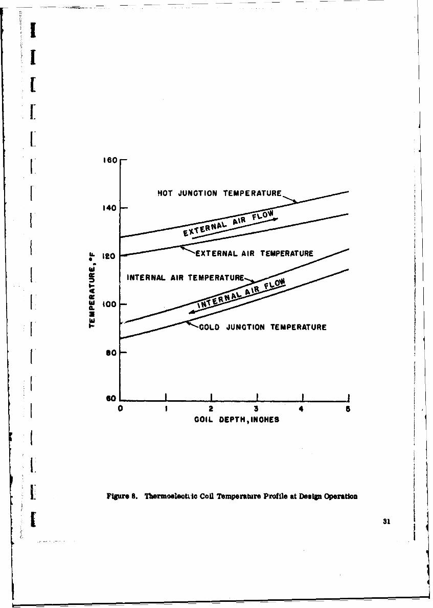
4.3 Operating Performance
Electronic analog computer calculations were made to determine the performance
characteristics of this system at off-design as well as at design conditions. The operating Lperformance at design condition was described in detail in Section 3, 3.2. Figure 8 shows
the plotted computer solution for the syatem operating at design conditions on 60 cycle
po-Aer. This plot shows how the element junction temperature and the internal and external
air temperatures vary with coil location.
I
j NOT JUNCTION TEMPERATURE
140
I12 T t XERNA L AIR TEMPERATURE
I 1100 INTERNAL AIR TEMPERATURE
so-
10 I2 3 4 5COI L DEPTH91NOHES
I Figure 18. Thermoeldieco Coil Temperature Profile at DeIg Operation

Off-design cooling performance was calculated for variations in outdoor ambient
temperature, internal supply air temperature and operating voltage. Heating performance
was calculated for variation in operating voltage. All calculations were made for both 60
and 400 cycle operation. The system power draw and COP are significantly affected by main -*
power frequency, whereas the change in cooling capacity is insignificant. Figures 9 and 10
show how system capacity varies with ambient temperature and operating voltage for supply
air temperature of 72 and 62 0 F, respectively. In both of these plots, the heating capacity
is based on a return air temperature of 50 0F. Note that zero amperage curves are shown
rather than zero voltage. The reason for this is that when the SCR's are shut off, there Is
still a back EMF on the system generated by the thermoelectric coil. In certain cases, this
generated voltage may exceed 60 volts. Figures 9 and 10 are of primary interest because they
give a good representation of how the system will perform under normally expected conditions
of operation. It is interesting to note that there is a large range of operation between zero
amperage heating and zero amperage cooling. Within this range, the system will control
the inside air temperature at the set point temperature of 67 0 F by simply turning the external
fans off and on as required.
Figure 11 shows how system performance during cooling operation varies with out-
door ambient air temperature and operating voltage. System capacity, power draw and co-
efficient of performance are all shown for 60 cycle operation and a supply air temperature
of 720F.
Figure 12 shows the same performance information when the supply air temperature
is 620F, and Figures 13 and 14 show similar curves for the system operating on 400 cycle
power.
Figures 15 and 16 show how system performance during full cooling operation
varies with outdoor ambient sir temperature and supply air temperature. Again system
capacity, power draw, and coefficient of performance may be determined from the plot. IFigure 15 represents 60 cycle operation and Figure 16 represents 400 cycle operation.
These two plots are of greatest interest because they represent how the system will operate IIn the manual cooling mode. They also show the system design operating condition.
The exact procedure used to calculate the performance information is located in Ithe calculation section of Copy No. 1 of this report. Tabulated data is also provided which
shows such information as operating current, fan power requirements, etc.
32 IL!

I:A60 OR 400 CYC LE POWERI: SUPPLY AIR TEMPERATURE COOLING - 720 FRETURN AIR TEMPERATURE HEATING a 50OF
1 50-
1 40-
1 30-
S 20-
00100 1
f0 0 AMPS HEATING Igo VOLTS
90 VOLTS HEATING COOLING
I ~10-100 VOLTS HEATING
1 0 AMPS \ 90 VOLTSto C COLING <COOLING
278 VOLTS HEATINGI'
s0 40 60 so00 120OUTSIDE AMBIENT TEMPERATURE, OF
FVgur 9. Operatfg Performance Curve Showing Capacity aFunction of Ambient Temperatue wan Operating Voltage
1 33

60 OR 400 CYCLE POWERSUPPLY AIR TEMPERATURE COOLING = 620 FRETURN AIR TEMPERATURE HEATING a500 F
s0o-
40-
30 T
20'
810- 278 VOLTS
COOLING
00 AMPS HEATING
90 VOLTS HEATNG
1S0 VOLTSI 9 ISOVOTS HEATINGJ COLIG
-278 VOLTS HEATING COOLING \VwT SIN
20 40 60 s0 10 120
OUTSIDE AMBIENT TEMPERATURE, OF
Filpre1.Opeatg floCrnmS CM O wiDg CW011 As a I
34

11 .4
2.21. 2.z~ ~
00
0/ / 030- 0.8, /
00
0.4
.0-
0001Nv- / - CONSTANT VOLTAGE
_.CONSTANT AMBIENTI lE MPERATU RE
SYTMPWE1RW KILOWATTS
Figure 11. systemu cooling PerformanceI (720F Supply Air Temperature, 6o Cycle Power)
I 35

F 2.0 1.8 1.6
//1.4
50
,1.2 Wa
z. 4.2 ii
40
-/ 0I
30 0.80
202
toILb , .
o I . ./ O
i "
, 0 ,, , 0 /
!0.
.0!
0 /
a/ -'-'- CONSTANT VOLTAGE.
10 !,Ii.... - CONSTANHT AMBIENT
TEMPERATURE; g
2o o I I .. . I . .. I I ]
02Y 4 6 S 0
SYSTEM POWER DRAW, KLOWATTS
Figure 12. Sysem Cooling Performnane
(720F Supply Air Temperature, 400 Cycle Power)
36 I

2.2 2.0 1.8 1.6
1.1 50 -
0~ z40- I 1.0 0
IL
30 / 0.802P/
7' .4 0.4~
I/ /)0 0
0 _ O.0
0 a 4 6 1
/YTD POE DRW 0.4wATFiur 13 yse Coineromac
/6* Supl Ai0eprtr,0CcePwr
I / / ".

ri
1.8 1.6
14
0- ,
,o ~~~1 ,'w1 ,1 o0.'C' z
I0/i / i / 4 o~u
40-(o
1.0 ,o,1 //IL
30 0
,/ / ,
" __, ' , ./ /., / 4 l [2 - 1 .
I0i / o/ 1/ I0
i,/,'/ ,, "I
0.400
0 [
i, I / / 02---o.rN o..I/ 0.00 10/
0 " "
2 40
4 /
S/ q/ -CONSTANT VOLTAGE- -CONSTANT AMBIENT [
/ / TEMPERATURE
0 2 4 10SYSTEM POWER DRAW, KILOWATTS
Figure 14. System Cooling Performaws(62F Spply Air Temperature, 400 Cycle Power)
38

TI1Iz
1 60-0 U.
%.0
30 0-0
2 fPOIN 0.I0 :-.
10 i0
SYTMPWEDRw ILATEAT U
Figure 15. 481,601 Cooling Performance1 (278 Volt operatIon, 60 Cycle power)
.1 39

70 0
60-0.
x
IL Bon 50 -
000 0
00
0 [
DEIG
-- CONSTANT AMBIENT
CONSTANT SUPPLYAIR TEMPERATURE
SYSTEM POWER DRAW, KILOWATTS
Figure is. system Cooling Performace(218 Volt Operation, 400 Cycle Power) I

5.0 MAINTENANCE PROCEDURES
5.1 Thermoelectric Module
Ii A thermoelectric module with a broken junction may either be replaced w-i a spare
module or electrically removed from the circuit while it physically remains in the thermo-
J electric col. To replace a thermoelectric moduln:
(1) Remove access cover from outside face.
1 (2) Identify the bank which contains the defective module,
(3) Remove the top module in this bank by sliding it up
about 1 inch and then out.
(4) Remove successive modules from the bank in the same
manner until the defective module has been removed.
(5) Replace with a spare module making sure that the
module connector pins are properly in place.
(6) Replace the other modules kato the bank, again insuring
that all connector pins are properly in place.
(7) Replace and fasten down the access cover.
If a spare module is not available, then a defective module may be electrically~removed from the circuit by the following procedure:
(1) Remove access cover from outside face.
(2) Remove the top module as described perviously.
(3) lemove successive modules from the bank in the same
manner until the defective module has been removed.
(4) After removal of the defective module, replace all other
modules into the bank such that each module is one position
Sbelow its original position.
(5) Leaving the Jumper strap in Its original position Pcross the
top of the uppermost module, replace the bad module into
the top position after removing the connector pins.
(6) lplace and fasten down the access cover.
I1 41
J J J J J M J JlJI

5.2 Internal Fan
In order to remove an internal fan:
(1) Remove access cover from outside face.
(2) Remove the internal air baffle from the front of the fans.
(3) Disconnect fan electrical connector.
(4) Remove fan mounting bolts and remove fan.
(5) Replace fan by reversing steps 1, 2, 3, and 4.
5.3 External Fan
To remove an external fan:
(1) Remove access cover from outside face.
(2) Disconnect fan electrical connector.
(3) Remove fan mounting bolts and remove fan.
(4) Replace fan by rever.- . steps 1, 2, and 3.
5.4 Control and Power Conversion Packag -
To remove the control and power conversion package: H
(1) Remove access cover from outside face.
(2) Remove one external fan.
(3) Remove all electrical connectors from control box.
(4) Remove screws fastening the control box to the unit Iframe and remove control box.
(5) Replace box by reversing steps 1, 2, 3, and 4. IITo remove a printed circuit card from the control and power conversion package: H
(1) Remove cover from package.
(2) Slip card from connector and replace with a spare card.
(3) Replace cover. 11
II,, flIt
42t

! I
To remove a bad diode or SCR from the rectifier bridge:
1 (1) Remove cover from the control box.
(2) Disconnect lead wires from the defective diode or SCR.
1 (3) Remove the defective component and replace with a spare.
Care should be exercised to prevent stripping the copper
j threads. If a torque wrench is available, the components
should be torqued to 30 in. -lb.
(4) Replace the lead wires.
(5) Replace cover.
j 5.5 Frequency Changeover
The fan motors rend the firing circuit for this system are frequency sensitive.
Consequently, they must be wired for the proper supply frequency. On the firing circuit,
a jumper wire must be removed when the unit is operated at 400 cycles. This wire is
marked as indicated on the schematic wiring diagram. Conversely, when operating on 60
cycle this wire must be connected in position.
[ The fan motors, are dual frequency with a separate set of lead wires for each
frequency. Each set of wires is connected to an MS connector. The connectors are clearly
Fmarked 60 cycle or 400 cycle. The proper connection is determined by the main power
supply frequency.
6.0 MANUFACTURING PROCEDURE
The manufacturing procedure used to process thermoelectric panels consistsprincipally of processing semiconductor elements and insulated conductor straps and
r assembling them into the panel circuit. Detailed process sheets are available which
:' I describe the exact step-by-step procedures that have been developed at Carrier's thermo-
electric process development nd pilot production facility. The applicable process sheets
are included in Appendix B.
II
II

7.0 COST ESTIMATE IThe Purchase Description requests a cost estimate for fabricating one prototype J
unit and total costs for producing quantities of 10, 50 and 600 units per buy. A detailed
price analysis is presented in Figure 17 to show prototype development costs and an estimate
for producing ten units. An explanation is in order for these cost estimates as well as for
the larger production quantities.
Input data for the price analysis shown has been obtained from actual experience
using existing thermoelectric process development facilities and the manufacturing methods
described in the previous section. Existing facilities and procedures are adequate for pro-
totype development and for a limited production to meet the requirements of field trial qual-
ification. After absorption of non-recurring development costs, there would be only minor
differences in cost per unit up to the maximum capability of the existing facilities and using
the manufacturing procedures described earlier. In other words, after the first unit is Ideveloped, whether the additional requirement is for three units, five or ten, only slight
cost improvement would be possible. The maximum capability of the facility now in use iwould be about ten units, considering a reasonable delivery time for fabrication. Therefore,
the information presented in the price analysis for producing one and ten units should be.
regarded as reasonably representative for any number within this range, the major
difference for quantities smaller than ten being in material costs. Likewise, to reflect
substantial reductions in cost, a scale-up to meet volume production requirements would
be necessary. This, of course, is not reflected in the price for a range from one to ten
units.
For quantities of 50 and 600 units per buy, increased automation of routine pro-
cedures would be employed. High volume operations would justify capital expenditures to 1reduce labor costs and to improve process yield, both of which are significant percentages
of unit cost in small quantities as produced by existing methods. One of the major advantages
of producing a small number of units, say three to ten, would be to establish production
measures which could be employed for large scale-up in capacity. IIt is fully recognized that cost will play a major role in determining the ultimate
feasibility of thermoelectric systems. The advantages of reliability, size, weight and
performance characteristics will, in the final analysis, have to be related to cost in com-parison with a conventional system. Carrier believes that the effect of a scale-up to meet
true production requirements will be of major significance in reducing thermoelectric Isystem cost to a level where it is competitive with more conventional systems. We do not
4 I

CItIII_ AMit C()N)I'I)N/N( COMPANY
MI Io'I'AIHY .(tilI'MI'ENT I )i IAII'I'M'.NTr
Purcaser USAERDL, Fort Ilcivoir, Va. Contract No. DA-44-009-AMC-1135(T)
Proje'ct Thermoelectric Environmental Control Unit l);itu September, 1965
Applicable Spe. RFQ No. 65-181GD E.-itimated by
Typo Uits Thermoelectric Chckud by
Non-Recurring Production Production
PRICE ITEMIZATION Preproduction Costh Coats Costs(No. Unitsaj (No. Units_1 (No. Units 10)
ornwr MAl'EIALRaw Material 5,800 47,000
Ptirchased Parts ..... 4,700 35,100
FACTORY LAIOI
1 900 lirs at$ 3.95 7,505
14.60._lira at $ 2.50!lit ..r 36,250
FACTORY OVEIRIIEAD 145 %-, 1-0,882 52,563
ENGINEERING LAIOR
2000 llirat $6.50 /lir-- 13,
jnonlirs at $ 5.25/ /Ih 2.625 5,250
ENGINEERING OVEREIAD 85 % 11,050 2,231 4.463
DRAFTING LAUO11
500 llra at $ 4.25 /11r 2125
DRAFTING OVEIIIIEAD 85 %, 1,806 --
C)TfiIEI l)IIIE~CT COSTSS
i. -I.TING HATEIAL-S - CQ'r3
(&) Testing Labor: 100 hra at 3.95 x 2.45 968
k,) Testing Labor: 400 bra at 2.50 x 2.45 2,450
'rOTAl. MANUFACTURING COSTS 27,981 34,711 183,076
f GENERAL, & AI)MINISrIIATIVE ,XPINS ._J_% 4.197 5.,207 27.461
TOTAL. CS T 32,178 39,918 210,537
PiiFir o 3,.218 3,.992 21,054
MISCO'. MANI US COSTS
fo), _ _ _ _ _ _ _ - - - --,. - - - - - - - -
TOI'Al, i I,I,INQ PilClE (No. of Uiit .J.- - 35.196 43.910 231.501
Fi&zre 17. Detailed Price Analysia

believe, however, that it is possible, without the experience of prototype development and a
limited production for field evaluation purposes, to predict an accurate unit cost for large
volume requirements.
It is our belief that no une is in a better position to predict the cost of developing -
and producing a system of the type described than Carrier. We are the only company to
date that has developed and produced a thermoelectric air conditioning system for a com-
mercial application, namely the 28 units provided for the S.C. Johnson application described
previously. On the basis of this experience, we believe that a projection of c.osts to large
production quantities would be misleading until after the important first steps of prototype
development and limited production for field trial qualification have been completed success-
fully.
8.0 SUMMARY OF RESULTS
A system analysis has been completed for a 24,000 Btu/hr thermoelectric environ-
mental control unit. In this analysis an electronic analog computer was used to optimize
12 system parameters for minimum weight and maximum efficiency. All important sub-
systems and sub-system components were also analyzed by weighing the advantages and
disadvantages of the design possibilities considered.
From this analysis a design was formulated to meet the system requirements as
described in the Purchase Description. A complete set of assembly drawings are provided.
The resulting thermoelectric environmental control unit has outside dimensions of 28 inches
wide by 18 inches deep by 63 inches high, weighs 380 pounds and will provide 24,000 Btu/hr
cooling capacity at an overall system coefficient of performance of 1. 12.
Calculations were made to determine the off-design performance characteristics
of this system. Performance information is presented in graphical form, and a complete
description of how the system operates is included. Operating instructions, maintenance
procedures, manufacturing procedures and cost analysis information are also presented.
9.0 RECOMMENDATIONS [IOn the basis of the results presented herein, it is recommended that development
of a prototype unit be initiated. The objectives outlined in the Purchase Description have Ibeen met or exceeded by the design provided. Carrier is confident that a successful proto-
type unit can be built which will be in complete accord with all of the physical and perform- Hance characteristics of the design shown.
46 fl

It is estimated that delivery of a completed unit can be made within nine months
j from the date of contract award. As shown in the price analysis included in Section 7.0, the
estimated cost for producing one unit of the type designed is:
[ None-recurring developmental costs $35,196
Production cost 43,910
Total estimated cost $79,106
We will welcome the opportunity of working with USAERDL in developing this unit
[and believe that it is an important and worthwhile step in the application of thermoelectricity
to military requirements.
U
L
I
'if Li:

APPENDIX A
I LIST OF ASSEMBLY AND SCHEMATIC DRAWINGS
1.R0832 ae sy o . .EvrnetlCnrlUi2. R1058-430 Panue Assy. for T. E. Environmental Control Unit
3. R1058-9434 Frame Assembly for T. E. Environmental Control Unit
4. R1058-9431 Control and Monitor Panel for T. E. Environmental Control Unit
6 . R1058-3432 Temperature Sensor Assembly for T. E. Environmental Controlunit
16. R1058-9433 Power Conversion &oto akg o .E niomna
8. ~~~ Control Unit oto acaefrT . niomna
7. R08"6 Access Cover Assembly for T. E. Environmental Control Unit
8. R1068-9436 Unit Assembly for T. E, Environmental Control Unit
19. R1068-3437 Module Receptacle for T. E. Environmental Control Unit
10. R1(*6-943S Air flow Diagram for T. E. Environmental Control Unit
II 11. R.1058-4428 Schemnatic Diagram Control and Power Saply for T. E.Environmental Control Unit
A-i

~ob
.9~ w .
F 6 . . W -0
ILI
3 41 0 0 j090
9 .
wi -w
44.3 Wa
I xzrw oovz mo17 ~H L ! u
-~ E~E~LIi*asLEZJEJ911,I17L
(C~Wit

IlLD UP CAVITY FLUS" WITR OUTSIDE 5.z50 j.USING SILICON RUBBER 61 .RTV-IOt ,~ON EQUAL AS THE FILLE(R MATERIAL A 17
LAI
tp
ucmm AnrnImA

ITEMI SW. ATM. E O DEN S C I TI ON( FIIS DSIE)MAERA
I R I O S 8 3 4 1 9 4 P A N E L A S S Y ._ _ _ _ _ _ _
2 R I O S 4 4 3 0 - t 2 -0 0 T lK . 9 0S 0 H IG H . 1 .1 * 7 .1 1 1 1 . F IN N E D S T O C K
3 ___3 2 £ TN1K..AOO 416" .L25.1.479111 FINNED STOCK
4 -4 2 .020 75K.. 6;'- 1 L._ _ _ _
5 -5 2 .00 TH. 64 71 .G.ALUMINUM____-7-7
1 .010 711K.- S4 1 LQ.
8 1 _ DI A. -3, FE CTTN BS9 -9 2 D I A . . L GO ,E U T I G S S
r-AtAW
EEZ4
aa
BP-
wallR1058-44301
T

pi4DUI4 oo. DIELRIPTmM(w
33 NWA 0434-8 a TUv~iiI.WLL .
14 F035411N It IVTAI .TS. COU
s i i-111ss - IiE______ AM~e
I'-3 i25.SW Iz liVIE?,SLIMSSELF PLUG
__ __ __ __ __ _ __ __ _ __ _ 37 SSSSGAOMWIF 32 lKTS, BLINI StLIF RUtS6
114l*lI4% g ISV(:. BLIN, SELF FLU
p 35 NS1139 B NUT1. BLINS IlVSTFLAT* j-- * , 0 FSzlIII-S7 3e WT1, kWSSIV. FLAT NO,
41* MSZIItItI WT. LIND IVET, FLATN.41 M$027131 -S 35 at T, BLIND WAY.FLAT Hit
41 * . 4* It N
45 45 1I G 04TN..Z 11 $ILG.I~~~4 1 44I4O~I L.7&S
g a l f i l i f 1
0-0
-41 ma*1ThIT * * .low'
- w-
suo -
low 5*mms

ITMGGpTa!* ESCRIPTION (FINISHE I ZE ) RAT'LImZNil Lim n.PNTNA. at OtSCRIPTIAI (FINIHED D~E NLC31 W4Ati ESCRIPTION( FINIISE i)- - 4404-33411 to '* ..li~ - s k9G.43N-1I ANG - ItI .1 . 6LG. _ _ _
-- 0-No.-- -- "W- I- - RIO ~ _ _75121115INuito 4 IlGAtNG 7451 If..&NNLL.AI 3 '1 It ANGLE- itIj 6 LI.433 Z6 ONO-4 It RIVET, BLIND, SELFPLUGGING.AAIA to £2 6 SQUAR TUBE - Ii; WALL - LN. Lo. -4 1 ANGL -Ijli V 1.ZLSI: 37 Hit""'4-NW It Vt. BLIND .LF PLGGIN- IA. Ii !0 13GI -.10THIL..2j.2I(NuuETOPECESJ 5 - S4 IANL.IIi&Z L4
30 434W44--4U4 IN RIVET, SLINO. SELF PLIIUIIII 14. It It 0N1 -.IO 4.4 (MAKES TIPI[CNS) - NNL4~I~AtIA"13" NTIS "U~,INDfIVT*F34I W CLANIDENCI-ow Ell -23 1 T7E 7. 1.TN.TL._____4IAAEI.i&2~G
40 N621134. 2T W04T. KIND RVET.FLT NoCLOSED EN3DT 4 Z4 -14 4 NAN. 3DN.LS.- ~ S - 0 AGGj .. r-, I -- - --- _____- - - -- - ___1_ANGLE______1[-&_____LIS
4t 621. 3t im. KIND RIYNT. RAT4 No. uo.bmgTOIV tN -26 3 01.S -CO A 0 ,... - -
THEE 1N It
44 -46 1 2343TH131 I~.7~A .-0 IITwit.S.jL -lN 36 AKI-11. Ii.1.7 S
.301 I 0N .N).30ali _
SLU ISNNft
IN46
1Lu: oi S I.i I 2 B7U
Q312

.~~~~~ ~~ ... ...............
00 0
. 0
MODULE VOLTAGE
MAMAAL
2OO
AUT TO~ (NRET EXTERNAL FAN 10 6
ETOR WTC..UTO
FRONT ~IIW 84 SICTION
00
1.'I TA

I ~4t; 014 -I .1 wOf'4A 4--..4.. NOVEL - 7; it&1064
'7 mw '4 .6 9 *4 * S : ;',NJ * J 4 I T m. .St titi~
.~ ..~ ~ T. v JT OwRqt?'a 14 p 4 1 vNIPAn a.b 462jiA.______
20 14".-A& HIM4 *1 or~t "I' Laz.rI', f TNT *)4 -143Z t omt T ~f41 u so6 46).
"s "1044. Nol z 1*@ 12 ,.; -I U RO 40 1 .6 NUT41)4li* 9Ij M l PLITIC FMOT POCKSI
I 16 IS { 6.(14CM ; --- I
14 13 .9 - O~ S14 WITC VAl* -in a.44
' 1 Pt?)?? 3? UG7lAC 1 405-911RESE 101250814K3 I I UITCWCOUTROLS C&? O MF WEICAN
.1 j 1:Tsl )44 PIt mom ) iII?-gu~ Ctoi-N.l~I~StU __
14 j005&-143I.I WFI SlU I TAL S T.WCO IUCIA 60)2
00
o1
QzJW 4001Q
UCIO IKPVE
7 0@N 0-k ^
7 --T 009 mm homp
50IVA6m u soia

IN1" ~C\
2 .94, *. QQ
Q~~ I iI -0
U 41
2s 0! w-~-~
Do-go
Ci T 1 IJf7
1
tIb
.
UOp
00
I C=T=7~
- IRI ~z I .1.0C.

214
(3 -0Upx O MM&tTAP FULL DEPTH >4 ) r
(3~2 ax P k~c4~ltTAP PULL Carr" t '278 lt*I 01A.) DRILL
Iji hI.312 R
STIRLIma SU KPO.Y 22OR LUUAL
DETAULC 2AP
L DETAALL ^-'
23
+-
7j7 4
-LJLJ- IL
4X4)4 1n- C4 3-
ALM - j
dwgmo

O C-9)* 14S ma V1C~ C' 4" 1v
- -5 i~ j thjAi XJL$.4 uMAN ( U.I4CJ
k4~214i r1
j3~ ORIO KU AGAC240CWt 3 TRS OPS
it fe8,,iO -11 a TIIYRECTOR DOCOIASIAO __
12 3(51.2,3 JAN 2M W8 £ SILICON CONTR@LLIO IIPIt1911
3 1,3-- RIOSS-33-13 3 DI0DE - OhI *1,1747 615V 3SA4 4,C3,04 Rl008i431--4 3 bl031- G.E."IM3?71 4S10 SSA
15 6 Prc b-OARDo
_I7 MS 312AZS~C li3 COINECTOR- -
Is M51026 3-IS 3 CONNU!CORtP L044
-33-V 01C TAP -19-- ±ROS14I OMC~i ECI-A-DO WH END -L20 -20 1 TRMINIAL STRIP -KULKA -3
zi 21 I % X 2% M& ROD AUMVINum,6mITC
22-22 2 1! GA. (.090) x x :2 4. tOO Roo
24 -:4 3 X2 V4 V RECTI FIER MOYNT COPPER
26 111tI14421-4 IS O0tI THInG X I)X X '%* Lf ____
Z7 IR10S0-3624 19 .010 TIIK A OV* I% L64 CERAMAIC AI~O
24 IRIOSS-9431-26 I IIhACOb)X It f. 1. SUPOT StaT ALUIMINIII64*TI
-21113 4 PCsIOI 101 ITCHIOIS1511-3 PUPCI4ASE
30 j .30 1 11 GA(GM) x , x21 ROAR P61411. A "lSP,4-TS
3031 _-4i I 114 GA(O)08 coSI x6 1lt PA14EL __
u I-W 1 14 SA(.OSI) XC 47 K( log P61411is -33 1 14 A (.0611) X4 6 PARTITION
14 -34 1 14 GA (.00) X4Xz21 TOP P1111,421. _
36 - jS -15 14 ISAC(OW X 140 SOITTOM AM&L,1.__34 .8-1 14GA (to" 112 KIT% PCe SAT _
37 .~~~~37 8 lISA .6~~I.l.AR1 __
411,1111.10--1 17 '4-40 VA.5ICK 6CRIW,P60 ND PURCNASI
15 'I 4 -440 wVCX I, %A MMCRAW. PAM~ go______________ as "IS- 6611113 xO .4 WAIL 60aw.mm aS
44 -5104-I a 1_________IIIIIIL____________ m
+84 '004 34M-"IL -0W H W
Als? i ft W ISerN a .4 " c t usA
414

~/T H XHI. E P1X Y FOAMCOA71NG FREE FOAMEDPRIOR 0b FORMINGAS SHOWN
3 SECTION 27
___ ___ ___ ___ ___ ___ _ - 27
9~~~z -9 fl_ _ __ _ _
M A u nI l r LlT 1
7es mIr
mae aw - - - 63
L9it

ITEM DW4PARTNOSEft DESCRIPTION (FINIS NED SI *'SIIAL PURQIA$
IAE Riflsg 435* 1 1 j RECTANGULAR TUBE] ''j IS*ALL- 63LG.
Z _ PF.CTAOJGULAR TUBE- I-' IZS2 WALL - 63 LG.33 1
1 <TANGULAR TUE- . .IZS12 WMALL- 27 LG.
4 I4 1 ANGULAR TUBE t-A,.I25WALL- 27IL6. ALUMINUM
S -5~ 2 RECTANGULAR TUBE - f,' -.125 WVALL- 24'aLG.
6 .6 1 RECTANGULAR TUB .E-1 [11 -j.25-WALL. 24',L6.27j- -~ I Ii I RECTANGULAR TUBE- 11 .125 WALL- 24' LG.
_________________________________ 2 8-8 1 .063 TH. 9 -24 LG.
209 -9 2 .063TH.' - 13 LG.-~~~~1 10U..... -----...-.- 10 1 .063THK.-w' -~ 24' LG.
II .1 7.OESHE. S'GLG.ALUMINUM
12 -12 6 .0G3 TWK.- 1 1 -38itLG. (REFER 10 SECTION A.A)IS -13 1oTX I 1.OUrA.I21 1LG.
1314 .14 106 OUTWKE. - 1 j -27 'LG. _______
Is .1S 1 *3O MESH 'AIRE SCREEN ZSj 's4 71U.. STAINLESS STIL3U4
vI_ -16 2 EXPANDED METAL- [IBGA.(FLAT) l1*11A. STAINLESS SYL.30217 1I I41 THK. 41' -24i LUG t I . DUIV OITRA ii
-~ *CLEAR VINYL 04 11111PSEN.I
19 MSZ0600-B4WZ k RIVE~T, BLIND, SELF PUNCHI N&G LDlA.PRHS
ZoIS MZOBO-B4 77 RIVET, BLIND, SELF PUNCHING- CIWA.
WTII:
1 Nowm. moooi tolt to "Autm Will~ ns.).
-+
+m
"won "N s-s,1f~~ "W T_ _ __ _ nm R1058-44A5

I r
A I
231
a
IOU
AIP
6" D
,1, , , 3A "
, , . , ,
I~n
iS("
0+ l nnn n L I 'n
_.. ---m ,, ...
I,- ,,l

* -s 95604114 1 '984 AtIMLz 4-Os 44 le 60 "CYL ASlIMILI
I12 C41 ONTROL AND 40"'.O PiMII.
* '1662 POWER CAMV60SION A60 CONTROL PACAGEI RIOSIS4402 1 ACCESS COVR hSIIMILY
6 IOSO-23437 MOUL K4U11IPTACLI
44 0.5 0430 ALUMINUMTRI6~ ~ ~ I LIS93 .404 6 f. ____01__
10 1 .0600Mk.. 61 INA.
-11 2 111 .* I 25 .11 6. L~6.I IOME W61016
151.1 TUN. 11 4 1Lo. WEEK0 =noIw414 -14 12 Tt -hs6..t.1 IS6
_s 7siS Ij 0MM. .I .IGjL&
* '6 ~~6 2 TM..0LF f -17 6 1,1TN 10.III
Is0 .16 It2 TWK.. Ii III
li::IZ 71s2 TUN It 16 Mj
zo -U I I140..Zj.24 Hi W -
22 -U I I141..24 Z#LI a a
23 3 af "W. 1 1 kILI
lii I p13s. * 5.733 L 1
0~z I 212 2M*6.lmh
To .T TIMIR. OISIIICLPWMLOOUA
-4 -, - Z oyL MOE *I
o l 2 tO MN M . A T U C I M I IN 2 1 1
*9M@2I11 I 0MUCiii. KCIPTMCIL I MPINVO1 IM'
X612663 am 0 -6 IU. k SEESCmnhI am.36 3061*4 -10Ku US LMM. Muw AMIS
IT 016W?. U41 S *.I so" Us c.F jPMI RES N PUIChU
40 WHSM-4 t? S.~c~ 4-1W AMA. 1011 PANSIR MIUE-40 4 *I400k- 1% m~a~ 001,AN 40
41 0116111144406 a %.st W4 Mobm1101040 15111052 4 1anImalum6I~Um%40 IHS-II 04 4 140 It120 VIA I3 SKEWI _____
1Soa _______is
0font
WI
SAM"* as

oils
k 0 2 4.
444 2 2 4
I L ow
o 'lowC
0NO a

D. 0
-IS
*POM ,o T, LaI~ m k 01
6% *--b 7
-~ d (E TEWI

lA~i ouONCIE cy'r-I Cc '
C Ib
-t-
-% 0 00;1--n' ?oSC
6 ej
10 w
IA Isu6 m4 a
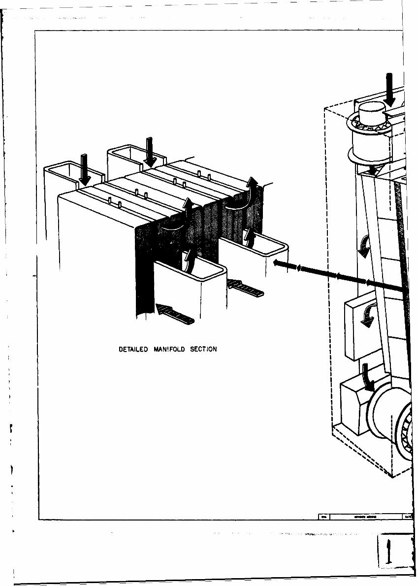
DETAILED MANIFOLD SECTION
Id
IL
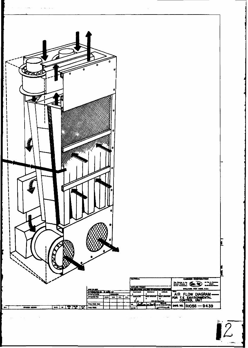
II% w4
low m==~~ ~ A -Pm -a a a AR FLOW DIAGRAM-a FOR j4QM7 ITAL
oom urO6 m Wtg, R105-9439

TEMPERATURE. SENSOR AMPLIFIER SCH4MITT TRIGER SIGNAL SHAPING
too. IIc
T14 ZA.OMj '0 t~ .?K S* 10
3AKt221
rR4OVIRn ~ TEMPRAUR P JoNLN.TtO
TRI t 0 N4 /3\ l U9 2 JAN R51
biy. VSSI Z0flI
it TRI
0070
bn- 101. R
Its Tills
144 CSI
SK~~~~~ m zott

AN 'ON sw" tFIRING CIRCU3IT
G NOTES.1 A IALL RESISTANCE VALUES AIRE AS SHOW~N ANJD ARE
41 " RATED AT '/ WATT WITH RESITANCE TOLERA~NC1sSoo AS (I WAT ) Or±S7,UNLE56S INDIC.AXED OTHERISE.
RIZ-ZK Ea.tESISTOR, roo is coNNU.crEv IN bLems wrnHRS5 I , VM AND WI1LL BE C905EN TO G1IVE A FULL 50ALE
AIJ2IS%4 660 is 0 DEFLEC-rION AT 300 VOL.16 AC.ROSS ALL THETR21 SA i I MODULES.
TR jPI .ALL CAPACITANCE VALUES ARE IN MIC~tOWARADS.A 40 VOLTS
'tTOM
FORf400 CPS OPERATIONJANIMf&4I
all
R40 41R4lZ.ZK 24S ~(I WAI) 6)TAH~
R44
za 44 ZB
!III1I jn CP PAN
"Nut
NiIt
u C,,
400"16M
Nm
"a SUkWATIe DIAGRAM- f - - aw - .01TU@L AND PowIR SUPPY
77 F OMONI
010mm wo I'mI. W,52

WYM50L __~ DE!5rCMIP1
___is I -rRANSISTc I I CAPAC rroR
MAIN WIRING *14 ANNG STANDED ALP14A NoYSI 9 PvrC C . 1PAN WIRING 44co A.G 5'Qrv- ALPHA, Mc.Sj1 PVr_ c I___ I_COMWTROL WIRtG**LO AVIG S-ANDIE ALPH, No Il PVC 04 1 _____
TAEMISTO~ VO4RING*.O AV4G 5141ILDED Ak..PHA M~o.?.t5a c 5 1 _____PULSE TR&%NSFORMU.! WIl~GZlr*?OAV#4Q '5VIILVD N.P8A, V40. ZY3CA
C.I I_ _
r.B I __ _ _ _
c to I _ __ _
c II I __ _ _ _ _
clz I _ _ _ _
CRI I RELAYCR?. ItRR I REVERSING RELFIZ I FAM KELhYmC I RLA'
MAN I ____
PT1 I PULSE~ T 21 NbP0
PTS ITRhmwS I -rotmsFoiti
R ( I POT EMITOMET!
R50 I __
R40 IRS0 IL I I INDUrCTOfRLt I
C&I I CliRculT S.60UAVcis% I I__ _ _ _ _
PLI I MAIN POVOM. Lir.Pi.! I PAN PONSL. LI(SNI I %%wNI r.Klvi? I -
V MIU VOLT ILt
T 14
RtLb I POTCITORKTaitRees IR64 1TH4 I M.T.C. TiftlMIIIC
Dtb 10
-r- --~~ *2T - -kW - - m
maI"soeum iNiI:g=

DE SCRIPT I ON MANUFACTUS TYPE No. RAT-ING SYMBOIR~ DES~CRIPTION MAMUFACTU?.Ei TYPE No. RATINGTRjkw 51 STOR it E. AINW1%1 _ . 1' 7ENER IODE GEW.INS"Ti. USNIN15SZ 5.&V4O0tAW
CA~PA lTOR SPRikGUE CMJl5OMPS ?.SMFD BOV St 1 ___ ____ USNIN96611 IGV400MWY______________ ___CPO5AIEBZZ4K .ZitAFD I00V 1 B I $ UWNN(4B ISV 400MW
________ ___CUS.54INIP3 '5OMFO 50V 1-4 I ____ HOFFMAN USNIN3M 4V IWAIT_______CP05AlEBUt~4.PAMrb ioy 1. 5 I ~III~ 1 1_______CIPOAIE SSM( .03SMF Oy 0 7.G If
_______ ____CPO5AIS2J ?-%2MFO 100V . __________ --l I- USwNINSO S.IV4 IWA TT____CPOSAIBB .O33WD 100V 7-8 1 THyRETOW. DIODVE GE ~szsk*Io_______ ~~~~CP05AIE5Z73KtZ b 100 ?- 1 ___________z4iArO.IO
_______E53K05MF 100V___ 'I_ ____ 109 1 4 1___ ______ 48PS .I MaS Z 1-11 1 ?JENSM DIODE GL4.INSTR.t-USNINSr.B ?.OV400Mw
____111 C.R-1 I SIUCON CON~T'ROLLED RECTIFIER G.E. JANZIN-cso 60 Gas 1A
RELAY R.S.M. MSZS-90t___ ___
_________ DUNCO KRIAML4DC BR- I I REC.TIn!z SBRIMGE GEN.,iNTR. vNo-Z1 140V, b.AEVERSING RELKY KURMAN IGLZCL.40C ____ R-?. It- V f1
FAJ4 KELhY r)~.2D I__ I DIODE G..E. 1N37f.7 rossy BSA,
___D I _
ZGtDC0 DI__ __ __ __ __ _______M~l U7c 11 o4 I I___ N__ _ _ ______l
-rltN ?O-RMEV. REGuL.Ub Q- I If GI _________ANING45 I2.OO*OWtbARSON UV. (.4 Ira__ 0e I _ _ _ __ _ _
POTE~iOETE. 5PfCTROL .-- lS. SK 0% 1 ____
___ __ __ __42-Z-I-IOK IOiK 0101 1
______4t-Z7-i-700 2.00.12 oDII I____ _ __ ___1 017. 1 _ _ _ _
f____t_ 015 1___
~INUTOR CARRIER I 1-34-" IAI.Il 014 1___
______ ~ ~ ~ ~ ~ ~ ~ ~ ~ I I____ -- 55~-t . 22 _ _ _ _
______I' S1___k_9_ ftiVUN AM 'l- Z4A t4 A fste c0 ' I I0CNOLbIN$
__ _ __ _ __ _ POV41L0N ,AODIL it 0-0tR I _ _ _ _ __ _ _
N.T.C. TgaRMISTOU. K%*'fIitU RILSSI IRS__ I_____
41r?.-EVR 1--10K 10K TM I______
______________ 1L.1 J% I " ll A lil
* MI10 v I'Mit IAUL I___t
RSSWT 11.6KT DIALCO t2M5-6 TRISU I _______ - - t5A
__914__I iaW1440I i ___
~SCHEMATIC DIAGPAA~ -.- ~ a- NCM OL AND Pomnum
"M mm W1Aif " t I......

APPENDIX B
PROCESS SHEETS
I
R-1058-1149 Waferizing of Material
R-1058-1225 Polishing Thermoelectric Encapsulated Wafers
R-1058-11 2 Tinning of Thermoelectric ElementsUR-1058-1185 RF Bonding of Ceramic Sandwiches
R-1058-1299 Thermoelectric Panel Assembly
R-1058-1226 Foaming of Thermoelectric Panels
[[
I
.1|pt
I

IC
42z L
4 00 42 Mw
z i1aa
Ad bie
-10 100*r4
K- &4
p3i£

I I A3tM I T 0 -aa
Ir44l
8*-
H I
40. +ILd
x z
42 !A'~2
ul18i 1]1WI-A

'ON
C: v+1~- z F f
d d
0 0
0 q f3
0z u0 ain im + z A A
hi V) -
I' I
0 0z~4 ~.N ZU
0 a i -4X j a
0 4cz - 4rAL a. Z Db
14 a
a. -a
R me - -c -- I- -
r44
-~k-4
oa. 011 0 1
I v ___a 0
00

'ON_________
CH H z -
Z 0, 0
+1 $ N 7
l e a, , . o #A. 2*j zz it ~
ori ) 3. z- 10wz 0 '-1~i
02 +1 Ct'- 4 O
* z. 21
1- 4 a- U 9 LIVc'g. 00 4)
2 z
0 k .05 ~ =O r4~
2 -i a 0 12, za~ iUh
o14 0 U JoA
4J~~~ Zc1 Q
c 00) 4 00#A a) -. 0 0C M -I
~). r40, ~ p44 p4 4~rI14 0+~~H4)1 4 34k
0) 0ri~ -- I f )0 v
(D 0
0 ) 4) ri 00TJ) 42 0 0 0' 1-
0) 0.~4)H 000' \)0 *.4H004 $4 m :0 C )41 4
Ss r- 0 04oV $40c 1 rI
0 x C4 0~ tod C0 0hciI3 04 0i 14 4) 0o toI
+)44)0 ~r-I H
-r4>, 4 - 40 0 804 4-) OOHI.,: "H A 0
+3 4a H- 4) ~~~~. 0 Em.a 1 --
U) 4. - :
H P4 944
o"! a) - bo: c .5 ~ ~~~~ 0- 40 S: C.4 C~C4 t0 4414 -A
Is 0 10 0) 0 00 0
0 . q4 N d :3 0
st
-I-.---

'ON
z 0 C
19 z 41I
z z0 4 4 4 00 z z
.8 a m q0 ILF r
*z a
z~ z H E4 042
je 00(14
w :, a I
s w 0.b -, g
OOz z0 0 C 0C
0~ H 0HV4 A 43 * 0 a
44 S 4 N O0 I---4,l - S. ra*OMO1.34
ii': 0 I iE119"V 43 00 0 -4 -JH 04N4
54 0 0 0s.
01 *H V4 to 04
0*- 4 d t 4
-- 1 1 .4 -4 1 .;4 4
Q. :9 4 - VC.II-oa011 .)4 .+ d1a )Cl1-440 as

w a
0 w
zz pz z 44 V4 'S ZV
z C.44 z z V_ 0 *b
- A ,-H C oa oZ - 1 .1
2 v+ I oo ~ Z
z ~ ~ *-w Ia 2 a4 z t3 4
0. w - --
UO~. 43-cid~~ ~~ 005 i 0 1
0 .3-
0 og ., Od
0 z
* .r4qH
.O -Ao P
r-I-
4 4 .4 4-)
~~4~%* 4A 4Jh *~3
4- 10 0 55
Kg 1

AgH 6ZT-Q~T-d ON
UN
'- j
444 4 0 C)
z A
CA z U
M 0
~.0c y0 oz z
- 4)z 4. a 0
zz C1w
" a 0 a
u 0 :5 (A
L6 -C 0 A. v. a w cO-.1
cc - 0
aH 11 --- 4- U- 02
0 0 * 3___
H A
L3 a4 .4
0
4Co jUC
Vo (Wrq4 4)C
4) 0O .r-4
4 0 1 w r -i o 04' E O 4 )
.4 (* 4 3H 0 : 0 ' 41. in. 0~ -0 to od r
00 64
d 9
43 431&~
.1 1 0
4) 4- 0,aIfa0 - q 0 44..............................
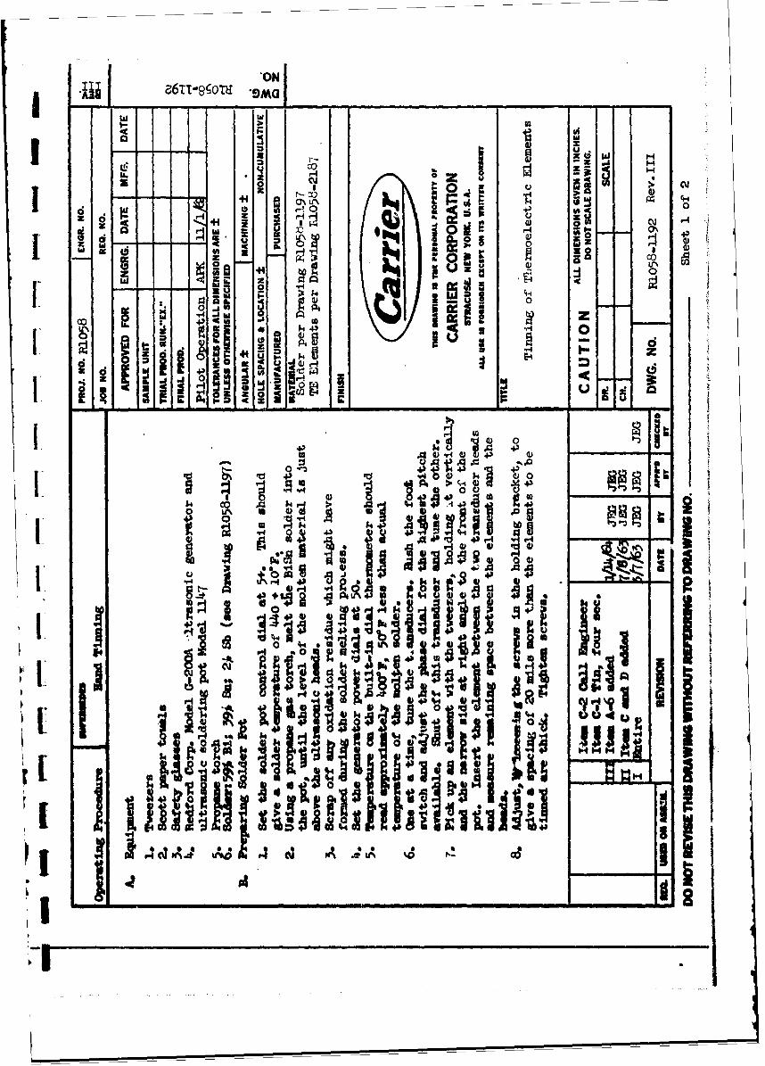
ZZ TP-T -!-IC
wU
a zw H
H Hz 0 cu
z I
*H H
0 1 . a
28 -. L \
0~ .
-.1 2 A 'I0___00 A rA a: 2 __
Iz I §~ $4d0 10
OH 43
03 to
A ~U
N434 0 0
43 IA Cd A i U1%

-;;-z a6r T1-qoTu 9M G J_ _ _ _ _ _ _ _ _ _w
h
-
Hj
10 d H-C z 4z +1 z 0 b
d z U zOC 'i!!- 0
0Ll
oj 440
0*
*1dho)
U ~ ' ~ .
z I 0 V64 5 i i~ ' I_ _ _ ' I
flip I
g. 1 ___ 1'r4
I i -)

III 9TTh9;6OTH 'ON
0~ U
- -U gz C. 00 +
U o *CW mC, ~ Ih! :1
o'm
ha 0 0 .~r0
.- 04
* 00
ir4 'U h-A
443
is ~
4.
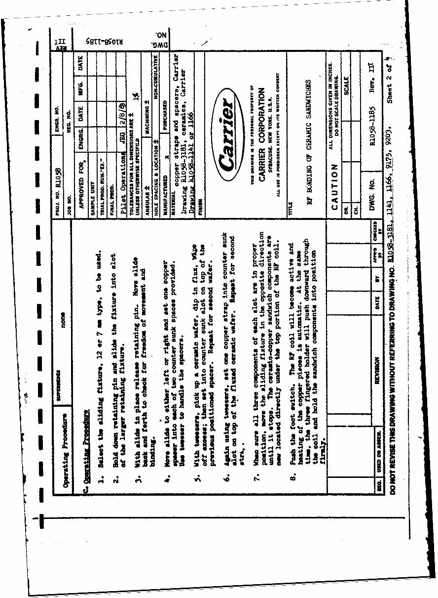
0N0III z8t
O 1 9M _ _
P~ 4c
d z
~ ~~I Z, vs
0__~~~
C->i- ,g -W0 - 0__ -- 0 'X
ozm
a.W z~~~.c
z wo
a. 5.0Q .1* 0b~ 441 S $l $ q 8
.4441 ~ 'oj 00. %
. '12. 430t
V4N(V 14 as 4 4_ _ _ _ _ _ _ _ _ _ _ _ _ _ _ _ _ _ __)_0 iI-0
1-4I

AJM -m -
x~ w
w~ IL V.
F l. -zU *
z d~(3 75- 0 )
,3 z 0i0 ~
hi~0 3:F 0.0 ~
20 (aa 0 U m ,14
z ~ ~ ~ h U)U U
Z0 0MitSU2 48tI * 4
C4 wr #A4.4
z 4.)
-44'
O~ . 4
o H' ~~4- ____
r..40 HH U)AU 4A
0 0 . H
0~i 4 - 200 j $4) 0ro 0
~~ 0*
t v . 1 0 r.4 **k.S 44h0
c 0 to VA
0
.4 9.4 _ _o6 & ji
o %4 1 4, to4

I 11I *AG9I 5TT-99ou
00 5 w
0
Ii 0 0eg m maH -- 0
'a' K W 'K 50It (~ g~It
co 0 ZA 0
coo 4cn .
Cl~
Io-~ ~! I
it4!!1

-0-
6" 0~0
r-
goi
, rdO
-%4 CC) w~. -
~flv4 I I
0~~~ '-A , O i
43 P-4 'rW .
4 42
I z0 .- r-4 -..,40'Ai 4) m A~ 1 j
lu _ z
4..-
LiL
lo 0ii J;
~ I pi!44
1* 4sC4C

A3m 66i-q(OiT *ON 'SAGj__________
45 1
4,$
0PB
I.- &f .
It'
Iva z
W4 4
IL I k
00
I Lw IA r4 Ott -W i40430443' I43i i i

66zt r '-T 1
AI, ON *San .-
0)0Ii'443
II ai ioC.C.
*14
J a
in A
.1
w EI- 0
1-44 0
,jo! toZ: +1 0
q- ac
0 -P-
Z1
4 F-~ +
~ bw
4-1P
-4>d
0)0)
I-,
0
43 0) .
w tDw 4 3 k ri43 ;4~-0 1 1 4
.0 **
4- Zt

9t- O0N -ama fA3V
A. Ci;
14 8 rirecnH
00 o
I. 0w +1 .0 hi
UNU
4z~ z +
U' -
0 z'E 1 1L~'4
U hii
IlIIC~t~rV4 1 Pik
PC%
.....i..

*A38 ON SMG t
00
I c
o a cu
w
0A w 0
5-4u J ; 4
H iw
0 +1 0 +
0 2 a
*r*Im u4W
4J 4'
0, u0 0 W
DO 0 a0
U.h U*-0f* .0 W a. 0
UH >4 L J +c u z
r 4 0) l
IN
54.
-H 4 4'~ 0 10 t' c
1 P4 40 ) 0 0 2p
zE P4 OZZ
z~a a
0 it C > Z a

Secwity 171assificationDOCUMENT CONTROL DATA - R&D
(Security cia4 m~iication of title. body of abstract anid Indexind er,.6tion must be entered when the overall report Is clssified)
1. OIGIP TN GACTVIT (Crpoateautor)20. REPORT SECURITY C LASSIFICATION
Car:'-ier Air Conditioning Company Unclassified
3. fEPOR TITLE
nie -noelectric Environmental Control Unit
14. DESCRIPTIVE NOTES (Type of report and Inclusive dotes)
Oina Engineering Design ReportS. AUTHOR(S) (Lose name. first name. Initiat)
r'.r~2nG.D.; Gable, G.K.; Beck, A.A.
-0 -'RT DATE [7a. TOTAL NO. OF PAGE$ __7 1NO. OF REFS
;eptember 1965 100f.CONTRACT OR GRANT NO. 98. ORIGINATOR'S REPORT NUMISER(S)
L C. .CT NO.
(3303D545 __________________
9 b. OTHER REPORT NO(S) (A ny other numbers that mey be s..?*led:
14. this report)
10 A VA IL ABILITY/LIMITATIOM NOTICES
G...Covernment agencies may obtain copies of this report directly f7rom DDC.K .~ qualified users shall request through 0NEFB-HH, USAERDL, Ft. Belvoir, Va.
vi", EMENTARY NOTES 12. SPONSORING MILITARY ACTIVITY
U. S. Army ERDLV Fort Belvoir, Virginia1 f RIACT
.~detailed engineering design is presented for a 241,000 Btu/hr Th ;r~eoelcz,Environmental Control Unit. System design is based on an optimw.,ai:on anperformed on an analog computer. Procedures followed and resul:zo obtaine?. aro:.described., Twelve design parameters were optimized for minimum weight and rn:x .
.efficiency.
.,ys-Gem is 28 in. wide x 18 in. deep x 63 in. high, weighs 380 lbs. andat an overall C.0.P. (including fans) of 1.12 with a net cooling capacity .)f'24),000 Btu/hr at design operating conditions. Dual frequency (60 and 4i00 nps'fans are used. Power rectifier furnishes 3 phase, full wave d-c ower w- ~izvoltage trar~sformation. Modulated capacity control is provided fcLrom full
:full heating as required by system load. The design is based o~n air-to-airat exchange utilizing aluminum heat transfer surface.
...pevrating instructions, maintenance procedures, manufacturing procedures an~d.cst analysis information are included.
.'econmendation is made to develop a prototype unit.
1 RIJ 1473JN , Uncl,%ssif:&e

See.rity -ClasS Elc.tionKY WORDS[ LINK A LINK B LINK C
..... _ _ __ _ _ __ _ S L W T -- - o tw r•ROLE WT ROLE WY ROLE V
Thermoelectric Heat Pump
Thermoelectric Environmental Control Unit
INSTRUCTIONSI. ORIGINATING ACTIVITY: Enter the name and address 10. AVAILABILITY/LIMITATION NOTICES: Enter any lim-
of the corari,,tor, subcontractor, grantee, Department of De- itations on further dissemination of the report, other than thoseIhe report. imposed by security classification, using standard statementssuch as:2a. REPt>R': SECURITY CLASSIFICATION: Enter the oer- () "Qualified requesters may obtain copies of thisall secur., :.. ifica:tion of the report. Indicate whether rp) f rm a t o e h"Rest,. ,._ .. L," is ,ncluded. Marking xs to be in accord- report from DDC."ance w,..., .,.oriate '. curity regulations. (2) "Foreign announcement and dissemination of this2b. 3 , ,
,,omatic downgrading is specified in DOD Di- report by DDC is not authorized."rectivt. ,- . " I and Armed Forces Industrial Manual. Enter (3) "U. S. Government agencies may obtain copies ofthe vr.'u-. %,r. -r. Also, when applicable, show that optional this report directly from DDC. Other qualified DDCmarkit.., .- , ..en used for Group 3 and Group 4 as author- users shall request throughized.
*3. R v;'C,.:" TITLE: Fnter the complete report title in all (4) "U S. military agencies may obtain copies of thisc ap it.. , ,.s. T itles in all case s should b e unclassified. r4t dirctl y fro m m a O t inq u oied u sIf a mc-an~ngfui iitle cannot be selected without classifica- report directly from DDC. Other qualified userstionc, s-ow tit:e e6assification in all capitals in parenthesis shall request throughimmediately tiulowing the title.
__
4. DESC..-.?TI,'E NOTES: If appropriate, enter the type of (5) "All distribution of this report is controlled. Qual-report, n.z., ,.ierim, progress, summary, annual, or final. ified DDC users shall request throughGive the in . ,sive dates when a specific reporting period is 1,covereu.
If the report has been furnished to the Office of Tecnnical5. AUTHOr(S): Enter the name(s) of author(s) as shown on Services, Department of Commerce, for sale to the public, indi-or in the r 4.1,r;. ,nter last name. first name, middle initial cate this fact and enter the price, if knownIf milli:-, ;cw rank and branch of service. The name ofthe pr,. .k,.. author is nn absolute minimum requirement. It. SUPPLEMENTARY NOTES: Use for additional explana-6. REPORT DATE. Enter the date of the report as day, tory notes.month, y.ar; or month, year. If more than one date eppears 12. SPON14ORING MILITARY ACTIVITY: Enter the name ofon the report, use date of p Abication, the departmental project office or laboratory sponsoring (pay.7a. TOTAL. NUMBER OF PAGES: The total page count ing for) the research and development. Include address.shoul folinv normal pagination procedures, i.e., enter the 13. ABSTRACT: Enter an abstract giving a brief and factualnumber c;h )ages containing information. summary of the document indicative of the report, even thoughit may also appear elsewhere in the body of the technical re-7b. NUMBER OF REFERENCES: Enter tle total number of port. If additional space is required, a continuation sheetreferences cited in the report. shall be attached.8a. CONTRACT OR GRANT NUMBER: If appropriate, enter It is highly desirable that the abstract of classified re-the applicable number of the contract or grant under which ports be unclassified. Each paragraph of the abstract shallthe reort was written. end with an indication of the military security classification8b, &:, & .id. PROJECT NUMBER: Enter the appropriate of the information in the paragraph, represented as (TS), (S).military -'.,_)ar *nt identification, such as project number, (C), or (U).subpr,.-,'c. r, system numbers, task number, etc. There is no limitation on the length of the abstract. How-9a. C 1... ,'OR'S REPORT NUMBER(S): Enter the offl. ever, the suggested length is from 150 to 225 words.cial t,.'r number by which the document will be identified 14. KEY WORDS: Key words are technically meaningful termsand controlled by the originating activity. This number must or short phrases that characterize a report and may be used asbe unique to this report. index entries for cataloging the report. Key words must be9b. OTHFW VFPORT NUMBER(S): If the report has been selected so that no security classification is required. Ide.n-assigned er report numbers (either by the originator tiers, such as equipment model designation, trade name,.or by the ,, or), also enter this number(s). tary project code name, geographic location, may be used as
key words but will be followed by an indication of technica;context. The assignment of links, rules, and weights isoptional.
Security Classification


![USDA Center for Veterinary Biologics Statistics Section€¦ · for such curve ts is the four-parameter logistic (4PL) curve [5, 13]. CVBSOP 0102 [16] illustrates such a curve tting](https://img.dokumen.tips/doc/110x75/6107af7bc69e9347eb16ea8f/usda-center-for-veterinary-biologics-statistics-section-for-such-curve-ts-is-the.jpg)