Embed Size (px)
Citation preview
TO 1-1-691TECHNICAL MANUAL
CLEANING AND CORROSION PREVENTIONAND CONTROL,
AEROSPACE AND NON-AEROSPACE EQUIPMENTF42620-00-D-0038FA8501-05-D-0002
DISTRIBUTION STATEMENT A - Approved for public release; distribution is unlimited (WR-ALC/PA Public Affairs Certification NumberPA04-11-96). Other request for this document shall be referred to 584 CBSS/GBHDE, Robins AFB, GA 31098. Questions concerning technicalcontent shall be referred to AFRL/MLS-OLR.
Published Under Authority of the Secretary of the Air Force.
1 JULY 2003 CHANGE 1 - 15 OCTOBER 2006

Dates of issue for original and changed pages are:
Original . . . . . . . .0 . . . . . . . .1 July 2003 Change . . . . . . 1 . . . . . . 15 October 2006
TOTAL NUMBER OF PAGES IN THIS PUBLICATION IS 350 CONSISTING OF THE FOLLOWING:
Page *ChangeNo. No.
Page *ChangeNo. No.
Page *ChangeNo. No.
Title . . . . . . . . . . . . . . . . . . . . . 1A . . . . . . . . . . . . . . . . . . . . . . . 1i - vii . . . . . . . . . . . . . . . . . . . . 1viii Blank. . . . . . . . . . . . . . . . . . 0ix . . . . . . . . . . . . . . . . . . . . . . . 1x . . . . . . . . . . . . . . . . . . . . . . . 0xi - xii . . . . . . . . . . . . . . . . . . . 1xiii . . . . . . . . . . . . . . . . . . . . . . 0xiv Blank. . . . . . . . . . . . . . . . . . 01-1 . . . . . . . . . . . . . . . . . . . . . . 11-2 . . . . . . . . . . . . . . . . . . . . . . 02-1 . . . . . . . . . . . . . . . . . . . . . . 12-2 - 2-20 . . . . . . . . . . . . . . . . . 02-21 . . . . . . . . . . . . . . . . . . . . . 12-22 . . . . . . . . . . . . . . . . . . . . . 03-1 - 3-12 . . . . . . . . . . . . . . . . . 13-13 - 3-14 . . . . . . . . . . . . . . . . 03-15 - 3-28 . . . . . . . . . . . . . . . . 13-28.1 Added . . . . . . . . . . . . . . . 13-28.2 Blank. . . . . . . . . . . . . . . . 13-29 - 3-33 . . . . . . . . . . . . . . . . 03-34 - 3-36 . . . . . . . . . . . . . . . . 13-37 . . . . . . . . . . . . . . . . . . . . . 03-38 - 3-41 . . . . . . . . . . . . . . . . 13-42 . . . . . . . . . . . . . . . . . . . . . 03-43 . . . . . . . . . . . . . . . . . . . . . 13-44 - 3-45 . . . . . . . . . . . . . . . . 03-46 - 3-48 . . . . . . . . . . . . . . . . 13-49 . . . . . . . . . . . . . . . . . . . . . 03-50 - 3-51 . . . . . . . . . . . . . . . . 13-52 . . . . . . . . . . . . . . . . . . . . . 03-53 - 3-61 . . . . . . . . . . . . . . . . 13-62 . . . . . . . . . . . . . . . . . . . . . 04-1 - 4-2. . . . . . . . . . . . . . . . . . 14-3 - 4-4. . . . . . . . . . . . . . . . . . 04-5 - 4-6. . . . . . . . . . . . . . . . . . 14-7 - 4-8. . . . . . . . . . . . . . . . . . 04-9 . . . . . . . . . . . . . . . . . . . . . . 14-10 - 4-13 . . . . . . . . . . . . . . . . 04-14 - 4-15 . . . . . . . . . . . . . . . . 14-16 - 4-18 . . . . . . . . . . . . . . . . 05-1 - 5-2. . . . . . . . . . . . . . . . . . 15-3 - 5-11 . . . . . . . . . . . . . . . . . 05-12 - 5-14 . . . . . . . . . . . . . . . . 15-15 - 5-16 . . . . . . . . . . . . . . . . 05-17 - 5-23 . . . . . . . . . . . . . . . . 1
5-24 . . . . . . . . . . . . . . . . . . . . . 05-25 . . . . . . . . . . . . . . . . . . . . . 15-26 . . . . . . . . . . . . . . . . . . . . . 05-27 - 5-29 . . . . . . . . . . . . . . . . 15-30 . . . . . . . . . . . . . . . . . . . . . 05-31 - 5-40 . . . . . . . . . . . . . . . . 15-41 . . . . . . . . . . . . . . . . . . . . . 05-42 . . . . . . . . . . . . . . . . . . . . . 15-43 - 5-44 . . . . . . . . . . . . . . . . 05-45 - 5-46 . . . . . . . . . . . . . . . . 15-47 . . . . . . . . . . . . . . . . . . . . . 05-48 . . . . . . . . . . . . . . . . . . . . . 15-49 - 5-51 . . . . . . . . . . . . . . . . 05-52 Blank. . . . . . . . . . . . . . . . . 06-1 . . . . . . . . . . . . . . . . . . . . . . 16-2 - 6-10 . . . . . . . . . . . . . . . . . 06-11 . . . . . . . . . . . . . . . . . . . . . 16-12 - 6-17 . . . . . . . . . . . . . . . . 06-18 - 6-22 . . . . . . . . . . . . . . . . 16-22.1 Added . . . . . . . . . . . . . . . 16-22.2 Blank. . . . . . . . . . . . . . . . 16-23 - 6-27 . . . . . . . . . . . . . . . . 16-28 . . . . . . . . . . . . . . . . . . . . . 06-29 - 6-30 . . . . . . . . . . . . . . . . 16-31 - 6-33 . . . . . . . . . . . . . . . . 06-34 Blank. . . . . . . . . . . . . . . . . 07-1 - 7-15 . . . . . . . . . . . . . . . . . 17-16 - 7-19 . . . . . . . . . . . . . . . . 07-20 Blank. . . . . . . . . . . . . . . . . 08-1 - 8-3. . . . . . . . . . . . . . . . . . 08-4 . . . . . . . . . . . . . . . . . . . . . . 18-5 . . . . . . . . . . . . . . . . . . . . . . 08-6 - 8-13 . . . . . . . . . . . . . . . . . 18-14 Blank. . . . . . . . . . . . . . . . . 09-1 - 9-3 Added. . . . . . . . . . . . . 19-4 Blank. . . . . . . . . . . . . . . . . . 1A-1 - A-3 . . . . . . . . . . . . . . . . . 0A-4 - A-5 . . . . . . . . . . . . . . . . . 1A-6 - A-8 . . . . . . . . . . . . . . . . . 0A-9 - A-10 . . . . . . . . . . . . . . . . 1A-11 . . . . . . . . . . . . . . . . . . . . . 0A-12 - A-18 . . . . . . . . . . . . . . . 1A-19 - A-21 . . . . . . . . . . . . . . . 0A-22 - A-23 . . . . . . . . . . . . . . . 1A-24 . . . . . . . . . . . . . . . . . . . . . 0A-25 . . . . . . . . . . . . . . . . . . . . . 1
A-26 - A-46 . . . . . . . . . . . . . . . 0B-1 . . . . . . . . . . . . . . . . . . . . . . 0B-2 - B-3 . . . . . . . . . . . . . . . . . 1B-4 - B-5 . . . . . . . . . . . . . . . . . 0B-6 - B-9 . . . . . . . . . . . . . . . . . 1B-10 - B-15. . . . . . . . . . . . . . . . 0B-16 . . . . . . . . . . . . . . . . . . . . . 1B-17 . . . . . . . . . . . . . . . . . . . . . 0B-18 - B-19. . . . . . . . . . . . . . . . 1B-20 - B-22. . . . . . . . . . . . . . . . 0B-23 . . . . . . . . . . . . . . . . . . . . . 1B-24 - B-33. . . . . . . . . . . . . . . . 0B-34 - B-39. . . . . . . . . . . . . . . . 1B-40 - B-42. . . . . . . . . . . . . . . . 0Glossary 1 . . . . . . . . . . . . . . . . . 1Glossary 2 - Glossary 4. . . . . . . . 0Index 1 . . . . . . . . . . . . . . . . . . . 0Index 2 . . . . . . . . . . . . . . . . . . . 1Index 3 . . . . . . . . . . . . . . . . . . . 0Index 4 - Index 6. . . . . . . . . . . . 1Index 6.1 Added . . . . . . . . . . . . . 1Index 6.2 Blank . . . . . . . . . . . . . 1Index 7 - Index 8. . . . . . . . . . . . 0
TO 1-1-691
LIST OF EFFECTIVE PAGESINSERT LATEST CHANGED PAGES. DESTROY SUPERSEDED PAGES.
NOTE The portion of the text affected by the changes is indicated by a vertical line in the outer margin ofthe page. Changes to illustrations are indicated by shaded or screened areas, or by miniaturepointing hands.
* Zero in this column indicates an original page.
USAFA Change 1

TABLE OF CONTENTS
Chapter Page Chapter Page
LIST OF ILLUSTRATIONS . . . . . . . . . . . vi
LIST OF TABLES . . . . . . . . . . . . . . . . . . vii
FOREWORD . . . . . . . . . . . . . . . . . . . . . ix
SAFETY SUMMARY . . . . . . . . . . . . . . . xiii
1 INTRODUCTION . . . . . . . . . . . . . . . . . . 1-1
1.1 CORROSION CONTROL PRO-GRAM . . . . . . . . . . . . . . . . . . 1-1
1.1.1 Training . . . . . . . . . . . . . . . . . . . 1-11.1.2 Maintenance . . . . . . . . . . . . . . . . 1-11.1.3 Facilities . . . . . . . . . . . . . . . . . . . 1-11.2 SAFETY . . . . . . . . . . . . . . . . . . 1-11.2.1 Responsibility of Supervisors . . . . . 1-11.2.2 Materials Handling . . . . . . . . . . . . 1-11.3 MATERIALS . . . . . . . . . . . . . . . 1-2
2 CORROSION THEORY . . . . . . . . . . . . . . 2-1
2.1 INTRODUCTION TO CORROSIONTHEORY . . . . . . . . . . . . . . . . 2-1
2.2 DEFINITION OF CORROSION . . 2-12.3 CHEMICAL DEFINITIONS . . . . . 2-12.3.1 Atom . . . . . . . . . . . . . . . . . . . . . 2-12.3.2 Electron . . . . . . . . . . . . . . . . . . . 2-12.3.3 Ions . . . . . . . . . . . . . . . . . . . . . . 2-12.3.4 Electrolyte . . . . . . . . . . . . . . . . . 2-12.4 THEORY OF CORROSION . . . . . 2-12.4.1 Anode . . . . . . . . . . . . . . . . . . . . 2-12.4.2 Cathode . . . . . . . . . . . . . . . . . . . 2-12.4.3 Electrolyte . . . . . . . . . . . . . . . . . 2-12.4.4 Electrical contact . . . . . . . . . . . . . 2-12.5 DEVELOPMENT OF CORRO-
SION . . . . . . . . . . . . . . . . . . . 2-22.5.1 Corrosion Under Painted Surfaces . . 2-22.6 FACTORS INFLUENCE CORRO-
SION . . . . . . . . . . . . . . . . . . . 2-22.6.1 Type of Metal . . . . . . . . . . . . . . . 2-32.6.2 Dissimilar Metal Coupling (Galvanic
Corrosion) . . . . . . . . . . . . . . . . 2-32.6.3 Anode and Cathode Surface Area . . 2-42.6.4 Temperature . . . . . . . . . . . . . . . . 2-42.6.5 Heat Treatment and Grain Direc-
tion . . . . . . . . . . . . . . . . . . . . 2-42.6.6 Electrolytes . . . . . . . . . . . . . . . . . 2-42.6.7 Oxygen . . . . . . . . . . . . . . . . . . . 2-42.6.8 Electrolyte Concentration . . . . . . . 2-52.6.9 Biological Organisms . . . . . . . . . . 2-52.6.10 Mechanical Stress . . . . . . . . . . . . 2-5
2.6.11 Time . . . . . . . . . . . . . . . . . . . . . 2-52.7 TYPES OF CORROSION . . . . . . . 2-52.7.1 Uniform Surface Corrosion . . . . . . 2-52.7.2 Galvanic Corrosion . . . . . . . . . . . . 2-52.7.3 Pitting Corrosion . . . . . . . . . . . . . 2-62.7.4 Intergranular Corrosion . . . . . . . . . 2-62.7.5 Exfoliation Corrosion . . . . . . . . . . 2-62.7.6 Crevice/Concentration Cell Corro-
sion . . . . . . . . . . . . . . . . . . . . 2-72.7.7 Corrosion Fatigue . . . . . . . . . . . . . 2-112.7.8 Filiform Corrosion . . . . . . . . . . . . 2-112.7.9 Fretting Corrosion . . . . . . . . . . . . 2-122.7.10 High Temperature Oxidation (Hot
Corrosion) . . . . . . . . . . . . . . . . 2-122.8 METALS AFFECTED BY CORRO-
SION . . . . . . . . . . . . . . . . . . . 2-122.8.1 Magnesium . . . . . . . . . . . . . . . . . 2-122.8.2 Steel . . . . . . . . . . . . . . . . . . . . . 2-132.8.3 Aluminum . . . . . . . . . . . . . . . . . . 2-132.8.4 Anodized Aluminum . . . . . . . . . . . 2-172.8.5 Titanium . . . . . . . . . . . . . . . . . . . 2-172.8.6 Copper and Copper Alloys . . . . . . . 2-172.8.7 Cadmium . . . . . . . . . . . . . . . . . . 2-172.8.8 CRES/Stainless Steel . . . . . . . . . . 2-172.8.9 Nickel and Chromium . . . . . . . . . . 2-182.8.10 Silver, Platinum, and Gold . . . . . . . 2-182.8.11 Graphite/Carbon Fiber Composites . 2-182.9 CORROSIVE ENVIRONMENTS . . 2-192.9.1 Moisture . . . . . . . . . . . . . . . . . . . 2-192.9.2 Temperature . . . . . . . . . . . . . . . . 2-192.9.3 Salt Atmospheres . . . . . . . . . . . . . 2-192.9.4 Ozone . . . . . . . . . . . . . . . . . . . . 2-192.9.5 Other Industrial Pollutants . . . . . . . 2-192.9.6 Sand, Dust, and Volcanic Ash . . . . 2-192.9.7 Solar Radiation . . . . . . . . . . . . . . 2-202.9.8 Climate . . . . . . . . . . . . . . . . . . . 2-202.9.9 Factors of Influence in Tropical En-
vironments . . . . . . . . . . . . . . . 2-202.9.10 Manufacturing . . . . . . . . . . . . . . . 2-202.9.11 Storage . . . . . . . . . . . . . . . . . . . . 2-212.9.12 Shipment . . . . . . . . . . . . . . . . . . 2-212.9.13 Industrial and Ship Emitted Air Pol-
lutants . . . . . . . . . . . . . . . . . . 2-212.9.14 Animal Damage . . . . . . . . . . . . . . 2-212.9.15 Micro-Organisms . . . . . . . . . . . . . 2-212.10 DEGRADATION OF NON-
METALS . . . . . . . . . . . . . . . . 2-222.11 PREVENTIVE MAINTENANCE . . 2-22
3 PREVENTIVE MAINTENANCE . . . . . . . . 3-1
SECTION I INTRODUCTION . . . . . . . . 3-1
TO 1-1-691
Change 1 i

3.1 PREVENTIVE MAINTENANCEPROGRAM . . . . . . . . . . . . . . . 3-1
3.1.1 Preventive Maintenance . . . . . . . . 3-1
SECTION II CLEANING . . . . . . . . . . . . 3-7
3.2 INTRODUCTION . . . . . . . . . . . . 3-73.2.1 Reasons for Cleaning . . . . . . . . . . 3-73.2.2 When to Accomplish Work . . . . . . 3-73.2.3 Aircraft Clear Water Rinse Require-
ments . . . . . . . . . . . . . . . . . . . 3-83.2.4 Immediate Cleaning . . . . . . . . . . . 3-83.3 CLEANING COMPOUNDS . . . . . 3-93.3.1 Alkaline Cleaners . . . . . . . . . . . . . 3-93.3.2 Solvent Emulsion and Aqueous
Cleaners for Turbine Engine GasPath and General Area Cleaning . 3-10
3.3.3 Aqueous Parts Washer Cleaning So-lutions . . . . . . . . . . . . . . . . . . 3-10
3.3.4 Solvents . . . . . . . . . . . . . . . . . . . 3-113.3.5 Miscellaneous Cleaning Agents . . . 3-113.3.6 Steam Cleaning . . . . . . . . . . . . . . 3-123.3.7 Dilution . . . . . . . . . . . . . . . . . . . 3-123.4 CLEANING EQUIPMENT . . . . . . 3-293.4.1 High Pressure/Hot Water Wash
Equipment . . . . . . . . . . . . . . . 3-293.4.2 Portable, 15 Gallon, Foam Generat-
ing, Cleaning Unit . . . . . . . . . . 3-293.4.3 Portable, 45 Gallon, Foam Generat-
ing Cleaning Unit . . . . . . . . . . . 3-303.4.4 Turbine Engine Compressor Clean-
ing Equipment . . . . . . . . . . . . . 3-343.4.5 Miscellaneous Large Cleaning
Equipment . . . . . . . . . . . . . . . 3-343.4.6 Spray Cleaning Guns for Solvents . 3-343.4.7 Pneumatic Vacuum Cleaner . . . . . . 3-343.4.8 Universal Wash Unit . . . . . . . . . . . 3-343.4.9 Aqueous Parts Washers . . . . . . . . . 3-343.4.10 Miscellaneous Equipment . . . . . . . 3-363.5 CLEANING PROCEDURES . . . . . 3-373.5.1 Warnings and Cautions . . . . . . . . . 3-373.5.2 Cleaning Methods . . . . . . . . . . . . 3-403.5.3 Clear Water Rinsing of Aircraft . . . 3-473.5.4 Post Cleaning Procedures . . . . . . . 3-473.5.5 Treatment and Disposal of Wash
Rack Waste . . . . . . . . . . . . . . . 3-483.5.6 Fungus Growth Removal . . . . . . . . 3-483.5.7 Soil Barriers . . . . . . . . . . . . . . . . 3-49
SECTION III LUBRICATION . . . . . . . . . 3-50
3.6 INTRODUCTION . . . . . . . . . . . . 3-503.6.1 Conventional Lubricants . . . . . . . . 3-503.6.2 Solid Film Lubricants . . . . . . . . . . 3-503.6.3 Application of Conventional Lubri-
cants . . . . . . . . . . . . . . . . . . . 3-51
SECTION IV PRESERVATION . . . . . . . . 3-53
3.7 INTRODUCTION . . . . . . . . . . . . 3-533.7.1 Operational Preservation . . . . . . . . 3-533.7.2 Non-Operational Preservation . . . . . 3-533.7.3 Types of CPC’s . . . . . . . . . . . . . . 3-533.7.4 Time Limitations of CPC’s . . . . . . 3-533.7.5 Description of CPC’s . . . . . . . . . . 3-563.7.6 Preservation of Speci c Areas . . . . 3-613.7.7 Preservation Application Methods . . 3-613.8 APPLICATION OF POLISH AND
WAX . . . . . . . . . . . . . . . . . . . 3-62
4 INSPECTION AND CORROSION PRONEAREAS . . . . . . . . . . . . . . . . . . . . . . . 4-1
SECTION I INSPECTION . . . . . . . . . . . 4-1
4.1 Purpose . . . . . . . . . . . . . . . . . . . 4-14.1.1 Responsibility . . . . . . . . . . . . . . . 4-14.1.2 Frequency of Inspections . . . . . . . . 4-14.1.3 General Inspections . . . . . . . . . . . 4-14.1.4 Detailed Inspections . . . . . . . . . . . 4-14.2 INSPECTION METHODS . . . . . . 4-14.2.1 Visual inspection . . . . . . . . . . . . . 4-14.2.2 Depth Gauge . . . . . . . . . . . . . . . . 4-24.2.3 Visual Inspection with a Borescope . 4-44.2.4 Optical Depth Micrometers. . . . . . . 4-44.2.5 Fluorescent Penetrant Inspection . . . 4-54.2.6 Eddy Current Inspection . . . . . . . . 4-64.2.7 Ultrasonic Inspection . . . . . . . . . . 4-64.2.8 Radiographic Inspection . . . . . . . . 4-64.3 EVALUATION OF CORROSION
DAMAGE . . . . . . . . . . . . . . . 4-84.4 DEGREES OF CORROSION . . . . 4-94.4.1 Light Corrosion . . . . . . . . . . . . . . 4-94.4.2 Moderate Corrosion . . . . . . . . . . . 4-94.4.3 Severe Corrosion . . . . . . . . . . . . . 4-9
SECTION II CORROSION PRONE AR-EAS . . . . . . . . . . . . . . . . . . . . . . . . . . 4-9
4.5 COMMON AREAS . . . . . . . . . . . 4-94.5.1 Fasteners . . . . . . . . . . . . . . . . . . 4-94.5.2 Faying Surfaces and Crevices . . . . 4-104.5.3 Spot-Welded Assemblies . . . . . . . . 4-104.5.4 Engine Exhaust and Gun Gas Im-
pingement Areas . . . . . . . . . . . 4-114.5.5 Wheel Wells and Landing Gear . . . 4-114.5.6 Flap and Slat Recesses . . . . . . . . . 4-114.5.7 Engine Frontal Areas and Air Inlet
Ducts . . . . . . . . . . . . . . . . . . . 4-124.5.8 Wing/Fin-Fold Joints and Wing and
Control Surface Leading Edges . 4-144.5.9 Hinges . . . . . . . . . . . . . . . . . . . . 4-14
TO 1-1-691
TABLE OF CONTENTS - CONTINUED
Chapter Page Chapter Page
ii Change 1
4.5.10 Control Cables . . . . . . . . . . . . . . . 4-144.5.11 Relief Tube Outlets . . . . . . . . . . . 4-144.5.12 Water Entrapment Areas . . . . . . . . 4-144.5.13 Bilge Areas . . . . . . . . . . . . . . . . . 4-144.5.14 Battery Compartments and Battery
Vent Openings . . . . . . . . . . . . . 4-144.5.15 Magnesium Parts . . . . . . . . . . . . . 4-154.5.16 Electrical Connectors and Other
Components . . . . . . . . . . . . . . 4-15
5 CORROSION REMOVAL AND SURFACETREATMENT . . . . . . . . . . . . . . . . . . . 5-1
SECTION I CORROSION REMOVAL . . 5-1
5.1 PURPOSE . . . . . . . . . . . . . . . . . 5-15.2 RESPONSIBILITY . . . . . . . . . . . 5-15.3 CORRECTIVE ACTIONS . . . . . . . 5-15.4 PAINT REMOVAL . . . . . . . . . . . 5-15.5 CORROSION REMOVAL . . . . . . . 5-15.5.1 Mechanical Methods . . . . . . . . . . . 5-25.5.2 Non-Powered Tools and Materials . 5-25.5.3 Power Tools and Materials . . . . . . 5-45.5.4 Abrasive Blasting . . . . . . . . . . . . . 5-95.6 SURFACE FINISH . . . . . . . . . . . 5-135.7 Pitting on Critical Structure . . . . . . 5-135.8 CORROSION REMOVAL
PROCEDURES-MECHANICAL . . . . . . . . . . . . 5-13
5.8.1 Warnings and Cautions . . . . . . . . . 5-135.8.2 Non-Powered Mechanical Corrosion
Removal . . . . . . . . . . . . . . . . . 5-165.8.3 Powered Mechanical Corrosion Re-
moval . . . . . . . . . . . . . . . . . . . 5-175.8.4 Abrasive Blasting Corrosion Re-
moval . . . . . . . . . . . . . . . . . . . 5-175.9 CORROSION REMOVAL-
CHEMICAL . . . . . . . . . . . . . . 5-185.9.1 Aluminum Alloys . . . . . . . . . . . . . 5-185.9.2 Magnesium Alloys . . . . . . . . . . . . 5-225.9.3 Ferrous Metal (Steel) Alloys Other
Than Stainless Steels (Cres) . . . . 5-235.9.4 Stainless Steel (Cres) And Nickel
Based Alloys . . . . . . . . . . . . . . 5-275.9.5 Copper And Copper Based Alloys . . 5-315.9.6 Titanium and Titanium Based Al-
loys . . . . . . . . . . . . . . . . . . . . 5-335.9.7 Plated And Phosphated Surfaces . . . 5-35
SECTION II SURFACE TREATMENT . . . 5-37
5.10 PURPOSE . . . . . . . . . . . . . . . . . 5-375.10.1 Chemical Prepaint Treatments . . . . 5-375.10.2 Surface Preparation . . . . . . . . . . . 5-395.10.3 Precautions . . . . . . . . . . . . . . . . . 5-405.10.4 Application of Surface Treatments . 5-40
5.10.5 Notes on Conversion Coating/Sur-face Treatment . . . . . . . . . . . . . 5-41
5.10.6 Post Treatment . . . . . . . . . . . . . . . 5-425.10.7 Temporary Preservation . . . . . . . . . 5-42
SECTION III SHOT PEENING/ROTO-PEENING . . . . . . . . . . . . . . . . . . . . . . 5-44
5.11 PEENING OF METAL SUR-FACES . . . . . . . . . . . . . . . . . . 5-44
5.11.1 Types of Peening . . . . . . . . . . . . . 5-445.11.2 Roto-Peening (Rotary Flap Peening)
Procedures . . . . . . . . . . . . . . . 5-45
6 SEALANTS . . . . . . . . . . . . . . . . . . . . . . 6-1
6.1 PURPOSE . . . . . . . . . . . . . . . . . 6-16.2 APPLICATIONS . . . . . . . . . . . . . 6-16.3 SEALING COMPOUNDS . . . . . . . 6-16.3.1 Sealant Packaging . . . . . . . . . . . . 6-16.3.2 Polysul de, Polyurethane, and Poly-
thioether Sealing Compounds . . . 6-16.3.3 Silicone Sealing Compounds . . . . . 6-26.3.4 Adhesion Promoters . . . . . . . . . . . 6-116.3.5 SAE AMS 3255 Oil and Water Re-
sistant, Expanded Polytetra uoro-ethylene Sealing Tape (EPTFE)Sky ex . . . . . . . . . . . . . . . . . . 6-11
6.3.6 Av-Dec® Polyurethane SealantTapes and Two Component Seal-ants . . . . . . . . . . . . . . . . . . . . 6-11
6.4 EQUIPMENT . . . . . . . . . . . . . . . 6-116.4.1 Sealant Gun . . . . . . . . . . . . . . . . 6-116.4.2 Application Nozzles . . . . . . . . . . . 6-116.4.3 Injection Gun . . . . . . . . . . . . . . . 6-116.4.4 Sealant Kits (Semkits®) . . . . . . . . 6-176.4.5 Sealant Removal and Application
Tools . . . . . . . . . . . . . . . . . . . 6-176.5 SEALANT MIXING . . . . . . . . . . 6-186.5.1 Application Life . . . . . . . . . . . . . . 6-196.5.2 Storage Instructions . . . . . . . . . . . 6-22.16.5.3 Mixing MIL-PRF-81733, Type III
Spray-able Sealant Coating . . . . 6-22.16.6 SEALANT APPLICATION PROCE-
DURES . . . . . . . . . . . . . . . . . 6-22.16.6.1 Cleaning . . . . . . . . . . . . . . . . . . . 6-236.6.2 Masking . . . . . . . . . . . . . . . . . . . 6-236.6.3 Adhesion Promoters . . . . . . . . . . . 6-236.6.4 Brush Spatula or Caulking Gun Ap-
plication . . . . . . . . . . . . . . . . . 6-236.6.5 Spray Gun Application . . . . . . . . . 6-246.6.6 Peel and Stick Application; AMS
3255 EPTFE Sky ex® and Av-Dec® HT3935-7 and HT3000Sealing Tapes . . . . . . . . . . . . . 6-24
6.7 SEALING OF SPECIFIC AREAS . 6-25
TO 1-1-691
TABLE OF CONTENTS - CONTINUED
Chapter Page Chapter Page
Change 1 iii

6.7.1 Faying Surface Sealing . . . . . . . . . 6-256.7.2 Fillet Sealing . . . . . . . . . . . . . . . . 6-266.7.3 Injection Sealing . . . . . . . . . . . . . 6-266.7.4 Fastener Sealing . . . . . . . . . . . . . . 6-266.7.5 Integral Fuel Cells/Tanks and Re-
movable Fuel Tanks . . . . . . . . . 6-276.7.6 Form-In-Place (FIP) Gasket Sealant
Repair . . . . . . . . . . . . . . . . . . 6-276.7.7 SAE AMS 3255 EPTFE (Sky ex®)
and Av-Dec® HT3000 andHT3935-7 Sealing Tape GasketRepair . . . . . . . . . . . . . . . . . . 6-27
6.7.8 External Aircraft Structure . . . . . . . 6-296.7.9 Depressions . . . . . . . . . . . . . . . . . 6-296.7.10 Damaged Sealant . . . . . . . . . . . . . 6-296.7.11 Extensive Repair . . . . . . . . . . . . . 6-306.7.12 High Temperature Areas . . . . . . . . 6-306.7.13 Low Temperature Curing . . . . . . . . 6-306.8 STORAGE/SHELF LIFE CON-
TROL OF SEALANTS . . . . . . . 6-30
7 TREATMENT OF SPECIFIC AREAS . . . . . 7-1
7.1 INTRODUCTION . . . . . . . . . . . . 7-17.2 BATTERY COMPARTMENTS,
BOXES, AND ADJACENT AR-EAS . . . . . . . . . . . . . . . . . . . . 7-1
7.2.1 Preparation of Solutions for Clean-ing and Neutralizing BatteryElectrolytes . . . . . . . . . . . . . . . 7-1
7.2.2 Cleaning and Neutralizing Proce-dures . . . . . . . . . . . . . . . . . . . 7-2
7.2.3 Paint Systems . . . . . . . . . . . . . . . 7-27.3 RELIEF TUBE AREAS . . . . . . . . 7-27.4 CORROSION TREATMENT FOR
STEEL CABLES . . . . . . . . . . . 7-37.5 PIANO TYPE HINGES . . . . . . . . 7-37.6 INTEGRAL AND EXTERNAL
FUEL TANKS AND DROPTANKS . . . . . . . . . . . . . . . . . 7-3
7.6.1 Corrosion Removal and Rework ofPitted Areas of Integral FuelTanks . . . . . . . . . . . . . . . . . . . 7-3
7.6.2 Removal of Corrosion and Reworkof Aluminum External FuelTanks/Drop Tanks . . . . . . . . . . 7-4
7.7 FAYING SURFACES AND AT-TACHMENT POINTS . . . . . . . 7-5
7.7.1 Faying Surfaces, Joints, and Seams . 7-57.7.2 Attaching Parts and Hardware . . . . 7-57.7.3 Severely Corroded (Rusted) Hard-
ware . . . . . . . . . . . . . . . . . . . . 7-67.8 NATURAL AND SYNTHETIC
RUBBER PARTS . . . . . . . . . . . 7-77.9 POTABLE WATER TANKS . . . . . 7-7
7.10 SURFACES AND COMPONENTSEXPOSED TO EXHAUSTGASES, GUN GASES ANDROCKET BLAST . . . . . . . . . . 7-7
7.11 ELECTRICAL AND ELECTRONICEQUIPMENT . . . . . . . . . . . . . 7-7
7.11.1 Grounding and Bonding Connec-tions . . . . . . . . . . . . . . . . . . . . 7-7
7.11.2 Conduit and Junction Boxes . . . . . 7-77.11.3 Wires and Cables . . . . . . . . . . . . . 7-77.11.4 Corrosion Protection for Electrical
Connectors, Lead-ins, etc . . . . . 7-77.11.5 Moisture and Fungus Proo ng of
Electrical and Electronic Equip-ment . . . . . . . . . . . . . . . . . . . 7-7
7.11.6 Antennas . . . . . . . . . . . . . . . . . . 7-77.12 STRUCTURAL TUBING MEM-
BERS AND ASSEMBLIES . . . . 7-77.12.1 Structural Aluminum Alloy Tubing . 7-77.12.2 Structural Magnesium Alloy Tub-
ing . . . . . . . . . . . . . . . . . . . . . 7-87.12.3 Structural Copper Alloys, Stainless
Steel (CRES) Alloys, and HeatResistant Alloy Tubing . . . . . . . 7-8
7.12.4 Structural Carbon Steel Tubing . . . . 7-87.13 NON-STRUCTURAL TUBING
MEMBERS AND ASSEM-BLIES . . . . . . . . . . . . . . . . . . 7-8
7.13.1 Aluminum Alloy Tubing . . . . . . . . 7-87.13.2 Stainless Steel (CRES) Tubing . . . . 7-97.13.3 Cadmium Plated Steel Tubing . . . . 7-97.13.4 Special Instructions for Tubing Fit-
tings and Sleeves . . . . . . . . . . . 7-107.13.5 Removable Installations . . . . . . . . 7-107.14 CORROSION REMOVAL FROM
THIN METAL (0.0625 INCHTHICKNESS AND LESS) . . . . . 7-10
7.15 AIR INTAKE DUCTS FOR JETAIRCRAFT . . . . . . . . . . . . . . . 7-11
7.16 CLOSELY COILED SPRINGS . . . 7-117.17 CORROSION PREVENTION ON
ASSEMBLIES AND PARTS RE-MOVED FROM AIRCRAFTDURING MAINTENANCE, 30DAY SHORT TERM STORAGE,AND OVER 30 DAY LONGTERM STORAGE REQUIRE-MENTS . . . . . . . . . . . . . . . . . 7-11
7.17.1 Short Term Storage . . . . . . . . . . . 7-117.17.2 Long Term Storage . . . . . . . . . . . . 7-117.18 DEPLETED URANIUM
COUNTER-WEIGHTS . . . . . . . 7-127.18.1 Corrosion and Finish Damage Treat-
ment Procedures . . . . . . . . . . . 7-127.19 MONEL RIVETS . . . . . . . . . . . . . 7-13
TO 1-1-691
TABLE OF CONTENTS - CONTINUED
Chapter Page Chapter Page
iv Change 1

7.20 BERYLLIUM-COPPER ALLOYS,BERYLLIUM-ALUMINUM AL-LOYS, AND BERYLLIUM OX-IDE . . . . . . . . . . . . . . . . . . . . 7-13
7.20.1 Corrosion Removal and Treatment . 7-137.20.2 Depot Maintenance . . . . . . . . . . . . 7-147.21 EMI SEALS AND GASKETS . . . . 7-147.21.1 Treatment of EMI Seals and Gas-
kets . . . . . . . . . . . . . . . . . . . . 7-14
8 EMERGENCY PROCEDURES . . . . . . . . . 8-1
8.1 PURPOSE . . . . . . . . . . . . . . . . . 8-18.2 RESPONSIBILITY . . . . . . . . . . . 8-18.3 EMERGENCY PREPARATIONS . . 8-18.3.1 Priority Removal List of Equipment
and/or Components . . . . . . . . . . 8-18.3.2 Emergency Reclamation Team . . . . 8-28.3.3 Emergency Reclamation Equip-
ment . . . . . . . . . . . . . . . . . . . 8-28.3.4 Production Planning . . . . . . . . . . . 8-28.4 GENERAL PROCEDURES . . . . . . 8-28.4.1 Removal of Contaminated Installed
Equipment . . . . . . . . . . . . . . . 8-58.4.2 Disassembly/Removal of Compo-
nents . . . . . . . . . . . . . . . . . . . 8-58.4.3 Clean . . . . . . . . . . . . . . . . . . . . . 8-58.4.4 Tagging . . . . . . . . . . . . . . . . . . . 8-58.5 GENERAL CLEANING PROCE-
DURES . . . . . . . . . . . . . . . . . 8-58.5.1 Primary Method . . . . . . . . . . . . . . 8-58.5.2 Alternate Methods . . . . . . . . . . . . 8-68.5.3 Removing O-D-1407 Potassium Bi-
carbonate (Purple K Powder/PKPor Other Dry Chemical Fire Ex-tinguishing Agents . . . . . . . . . . 8-6
8.5.4 Removing MIL-F-24385 AqueousFilm Forming Foam (AFFF) FireExtinguishing Agent . . . . . . . . . 8-7
8.5.5 Removal of Carbon Dioxide (CO2),HFC-125, or Halon Fire Extin-guishing Agents . . . . . . . . . . . . 8-7
8.5.6 Removal of Protein Type Foam andSoda-Acid Fire ExtinguishingAgents . . . . . . . . . . . . . . . . . . 8-7
8.5.7 Treatment After Landing on aFoamed Runway . . . . . . . . . . . 8-8
8.5.8 Treatment After Exposure to Volca-nic Ash . . . . . . . . . . . . . . . . . . 8-8
8.6 SPECIFIC INTERNAL AREAS . . . 8-88.6.1 Aircraft Cockpit Area . . . . . . . . . . 8-88.6.2 Aircraft Ejection Seats . . . . . . . . . 8-88.6.3 Avionic, Electronic and Electrical
Equipment . . . . . . . . . . . . . . . 8-9
8.6.4 Photographic Equipment . . . . . . . . 8-98.6.5 Graphite or Carbon Fiber/Epoxy,
Boron Fiber/Epoxy, and TungstenFiber/Epoxy Composite Materi-als . . . . . . . . . . . . . . . . . . . . . 8-9
8.7 SPECIFIC EXTERNAL AREAS OFAIRCRAFT . . . . . . . . . . . . . . . 8-10
8.7.1 Airframes . . . . . . . . . . . . . . . . . . 8-108.7.2 Antennas . . . . . . . . . . . . . . . . . . 8-108.7.3 Reciprocating Engines . . . . . . . . . 8-108.7.4 Turbine Engines . . . . . . . . . . . . . . 8-118.7.5 Treatment for Engines Which Have
Ingested Fire Extinguishing Pow-der (Purple K/PKP, Aqueous FilmForming Foam (AFFF), and/orSodium Bicarbonate) . . . . . . . . 8-11
8.7.6 Helicopter Transmission, RotorHead, and Rotor Hub . . . . . . . . 8-11
8.7.7 Helicopter Main and Tail RotorBlades . . . . . . . . . . . . . . . . . . 8-12
8.7.8 Armament . . . . . . . . . . . . . . . . . . 8-128.7.9 Aircraft Fuel Systems . . . . . . . . . . 8-13
9 SOUTHWEST ASIA ENVIRONMENTS . . . 9-1
9.1 INTRODUCTION . . . . . . . . . . . . 9-19.1.1 Climatic Conditions . . . . . . . . . . . 9-19.1.2 Aircraft Wash . . . . . . . . . . . . . . . 9-29.1.3 Aircraft Clear Water Rinse (CWR) . 9-29.1.4 Effects of Desert Environment . . . . 9-29.2 PRE-DEPLOYMENT RECOM-
MENDATIONS . . . . . . . . . . . . 9-29.3 RECOMMENDED ACTIONS
WHILE DEPLOYED . . . . . . . . 9-29.3.1 High Efficiency Particulate Air
(HEPA) Filtration . . . . . . . . . . . 9-29.3.2 Areas to be Checked and Cleaned . . 9-39.4 POST DEPLOYMENT . . . . . . . . . 9-39.5 CORROSION PREVENTIVE COM-
POUNDS (CPC’s) . . . . . . . . . . 9-39.5.1 Recommended CPC’s . . . . . . . . . . 9-3
APPENDIX A CONSUMABLE MATERI-ALS . . . . . . . . . . . . . . . . . . . . . . . . . . A-1
APPENDIX B EQUIPMENT FORCLEANING AND CORROSION PRE-VENTION AND CONTROL . . . . . . . . . B-1
GLOSSARY . . . . . . . . . . . . . . . . . . . . . .Glossary-1
INDEX . . . . . . . . . . . . . . . . . . . . . . . . . . Index-1
TO 1-1-691
TABLE OF CONTENTS - CONTINUED
Chapter Page Chapter Page
Change 1 v

LIST OF ILLUSTRATIONS
Figure Title Page Figure Title Page
2-1 Simpli ed Corrosion Cell . . . . . . . . . . 2-12-2 Elimination of Corrosion by Application
of an Organic Film to a MetalSurface . . . . . . . . . . . . . . . . . . . . 2-2
2-3 Effect of Sea Water on GalvanicCorrosion . . . . . . . . . . . . . . . . . . . 2-3
2-4 Galvanic Corrosion in a FlashlightBattery . . . . . . . . . . . . . . . . . . . . 2-4
2-5 Effect of Area Relationship in DissimilarMetal Contacts . . . . . . . . . . . . . . . 2-4
2-6 Galvanic Corrosion of MagnesiumAdjacent to a Steel Fastener . . . . . . 2-5
2-7 Pitting of an Aluminum WingAssembly . . . . . . . . . . . . . . . . . . . 2-6
2-8 Cross-section of Corrosion Pits . . . . . . 2-62-9 Cross-section of 7075-T6 Aluminum
Alloy . . . . . . . . . . . . . . . . . . . . . 2-72-10 Grain Structure of a Corroding
Aluminum Surface . . . . . . . . . . . . 2-72-11 Intergranular Corrosion of 7075-T6
Aluminum Adjacent to SteelFastener . . . . . . . . . . . . . . . . . . . . 2-7
2-12 Example of Exfoliation . . . . . . . . . . . 2-72-13 Another Example of Exfoliation . . . . . 2-82-14 Concentration Cell Corrosion . . . . . . . 2-92-15 Stress Corrosion Cracking . . . . . . . . . 2-92-16 Galvanic Series of Metals and Alloys in
Sea Water . . . . . . . . . . . . . . . . . . 2-102-17 Filiform Corrosion Found Under Paint
Coating on a Magnesium Panel . . . . 2-112-18 Schematic of the Development of
Filiform Corrosion on an AluminumAlloy . . . . . . . . . . . . . . . . . . . . . 2-12
2-19 Magnesium Corrosion Products . . . . . . 2-132-20 Steel Corrosion Products (Rust) . . . . . . 2-142-21 Aluminum Surface Corrosion Products . 2-152-22 Cadmium Plated Surface Conditions . . 2-162-23 Failed Chromium Plating . . . . . . . . . . 2-183-1 Foam Generating Cleaning Unit (15
Gallons) . . . . . . . . . . . . . . . . . . . . 3-303-2 Foam Generating Cleaning Unit (45
Gallons) . . . . . . . . . . . . . . . . . . . . 3-313-3 Universal Wash Unit . . . . . . . . . . . . . 3-333-4 Top Loading Type . . . . . . . . . . . . . . . 3-363-5 Front Loading Type . . . . . . . . . . . . . . 3-373-6 Use of Aircraft Washing Applicator . . . 3-413-7 Aircraft Cleaning Procedure . . . . . . . . 3-423-8 Automatic Water Spray Nozzle . . . . . . 3-454-1 Depth Dimension of Corrosion Pits . . . 4-34-2 Fiber Optic Borescope . . . . . . . . . . . . 4-44-3 Optical Depth Micrometer (Analog
Mechanical Read Out Type) . . . . . . 4-74-4 Optical Depth Micrometer (Digital Read
Out Type) . . . . . . . . . . . . . . . . . . 4-8
4-5 Typical Use of a Straight Edge toDetermine if Suspect Areas HaveBeen Previously Reworked . . . . . . . 4-9
4-6 Corrosion Around Fasteners . . . . . . . . 4-104-7 Galvanic Corrosion of Aluminum
Adjacent to Steel Fasteners . . . . . . . 4-104-8 Spot Weld Corrosion . . . . . . . . . . . . . 4-114-9 Spot Welded Skin Corrosion
Mechanism . . . . . . . . . . . . . . . . . 4-124-10 Gun Blast Area Corrosion Points . . . . . 4-124-11 Exhaust Trail Area Corrosion Points . . . 4-124-12 F-15 Nose Landing Gear Wheel Well . . 4-134-13 Flaps Lowered to Expose Recess
Areas . . . . . . . . . . . . . . . . . . . . . 4-134-14 Reciprocating Engine Frontal Area
Corrosion Points . . . . . . . . . . . . . . 4-134-15 Jet Engine Frontal Area Corrosion
Points . . . . . . . . . . . . . . . . . . . . . 4-134-16 Corrosion Prone Point of Air Inlet . . . . 4-134-17 Corrosion in Air Intake Duct . . . . . . . . 4-144-18 Wing Fold Joint . . . . . . . . . . . . . . . . 4-154-19 Hinge Corrosion Points . . . . . . . . . . . 4-164-20 Piano Hinge Lugs . . . . . . . . . . . . . . . 4-164-21 Control Cables . . . . . . . . . . . . . . . . . 4-164-22 Personnel Relief Tube Vent . . . . . . . . . 4-164-23 Common Water Entrapment Areas . . . . 4-174-24 Bilge Areas . . . . . . . . . . . . . . . . . . . 4-174-25 Battery Compartment . . . . . . . . . . . . . 4-185-1 3M Co. Scotch-BriteTM Flap Brush and
Mandrel . . . . . . . . . . . . . . . . . . . . 5-55-2 Abrasive Flap Wheels with Spindle
Mount . . . . . . . . . . . . . . . . . . . . . 5-55-3 3M Co. Radial Bristle Disc . . . . . . . . . 5-65-4 3M Co. Roloc Discs . . . . . . . . . . . . . 5-65-5 3M Co. Inline Bristle Disc . . . . . . . . . 5-85-6 Abrasive Blasting Equipment . . . . . . . 5-105-7 Shaping Reworked Areas . . . . . . . . . . 5-155-8 Acceptable Clean-up of Pitting
Corrosion on Critical Structure . . . . 5-155-9 Limited Clearance . . . . . . . . . . . . . . . 5-165-10 A Water-Break Free Surface Compared
with One with Breaks . . . . . . . . . . 5-415-11 Peening Intensity Conversion Graph (Isp
to Irp) . . . . . . . . . . . . . . . . . . . . . 5-485-12 Saturation Coverage Curves for
MIL-W-81840, Type I Wheels . . . . . 5-495-13 Saturation Coverage Curves for
MIL-W-81840, Type II Wheels(Flaps) . . . . . . . . . . . . . . . . . . . . . 5-50
5-14 Flap De ection Ranges . . . . . . . . . . . 5-516-1 Pneumatic Sealant Gun . . . . . . . . . . . 6-126-2 Sealant Application Nozzles . . . . . . . . 6-136-3 Countersink Application Nozzles . . . . . 6-14
TO 1-1-691
vi Change 1

6-4 Rivet Application Nozzles . . . . . . . . . 6-156-5 Sealant and Adhesive Smoothing Tools . 6-166-6 Sealant Injection Guns . . . . . . . . . . . . 6-176-7 Injection Style Semkit® . . . . . . . . . . . 6-186-8 Non-metallic Spatula . . . . . . . . . . . . . 6-246-9 Faying Surface Sealing . . . . . . . . . . . 6-266-10 Typical Fillet Seal . . . . . . . . . . . . . . . 6-276-11 Typical Injection Seal . . . . . . . . . . . . 6-286-12 Typical Methods of Sealing Fasteners . . 6-286-13 Typical Lap Skin Sealing . . . . . . . . . . 6-306-14 Sealing Procedures for Typical Aircraft
Fitting . . . . . . . . . . . . . . . . . . . . . 6-326-15 Typical Spar Cap Sealing . . . . . . . . . . 6-336-16 Sealing of Access Doors . . . . . . . . . . 6-347-1 Beryllium-Copper Spiral Contact With
Environmental Fluorosilicone Seal . . 7-15
7-2 Dorsal Longeron EMI Seal . . . . . . . . . 7-167-3 Stainless Steel (CRES) EMI Screen . . . 7-177-4 Bonding Cable From Airframe To
Graphite/Epoxy Avionics Bay Door . 7-187-5 EMI Bonding Washers in an Avionics
Bay . . . . . . . . . . . . . . . . . . . . . . . 7-199-1 Soil Makeup in the SWA Area . . . . . . 9-19-2 Global Dust Producing Regions . . . . . . 9-29-3 Open Circuit Board . . . . . . . . . . . . . . 9-3B-1 Back Mounted Full Facepiece
Respirator . . . . . . . . . . . . . . . . . . B-41B-2 Front Mounted Full Facepiece
Respirator . . . . . . . . . . . . . . . . . . B-42B-3 Hooded Air Respirator System . . . . . . B-43
LIST OF TABLES
Table Title Page Table Title Page
2-1 Corrosion of Metals - Type of Attack andAppearance of Corrosion Products . . . 2-16
3-1 Aircraft Wash Intervals . . . . . . . . . . . . . 3-23-2 Cleaning of Specific Areas and
Components . . . . . . . . . . . . . . . . . . 3-123-3 Recommended Dilution of Low
Temperature Cleaner . . . . . . . . . . . . . 3-463-4 Common Military Greases the Their
Uses . . . . . . . . . . . . . . . . . . . . . . . . 3-523-5 Time Limitations for CPC’s . . . . . . . . . . 3-543-6 Corrosion Preventive Compounds . . . . . . 3-543-7 Preservation of Specific Areas and
Components . . . . . . . . . . . . . . . . . . 3-574-1 NDI Inspection Tools for Various Types of
Corrosion . . . . . . . . . . . . . . . . . . . . 4-25-1 Grades of Abrasive Mats . . . . . . . . . . . . 5-25-2 Grades of Steel Wool . . . . . . . . . . . . . . 5-25-3 Recommended Powered Abrasives for
Corrosion Removal . . . . . . . . . . . . . . 5-115-4 Recommended Non-Powered Abrasives for
Corrosion Removal . . . . . . . . . . . . . . 5-125-5 Typical Chemical Corrosion Removal
Procedures For Aluminum Alloy Partsand Assemblies . . . . . . . . . . . . . . . . 5-20
5-6 Typical Chemical Corrosion RemovalProcedures for Magnesium Alloys . . . . 5-23
5-7 Typical Chemical Corrosion RemovalProcedures for Ferrous Metals OtherThan Stainless Steel (CRES) . . . . . . . 5-27
5-8 Typical Chemical Corrosion RemovalProcedures for Stainless Steel (CRES)and Nickel Based Alloys . . . . . . . . . . 5-29
5-9 Control of Corrosion Removal/ PicklingAction of Nitric-Hydrofluoric AcidSolutions . . . . . . . . . . . . . . . . . . . . 5-31
5-10 Typical Chemical Corrosion RemovalProcedures for Copper and CopperAlloys . . . . . . . . . . . . . . . . . . . . . . 5-33
5-11 Typical Chemical Corrosion Removal ofTitanium and Titanium Base Alloys . . 5-34
5-12 Typical Chemical Corrosion RemovalProcedures for Plated and PhosphatedSurfaces . . . . . . . . . . . . . . . . . . . . . 5-37
5-13 Prepaint Treatments for Metal Surfaces . . 5-425-14 Tool Operation Speed Requirements . . . . 5-465-15 Standard Peening Intensity (Isp) for
Complete Coverage Arc-Height inInches . . . . . . . . . . . . . . . . . . . . . . 5-46
6-1 Sealing Compounds . . . . . . . . . . . . . . . 6-36-2 Time Requirements for Sealants When
Used At 75 Degree F (24 Degree C)and 50 Precent RH . . . . . . . . . . . . . . 6-19
8-1 Priority Guide for Emergency Treatmentof Aircraft, Missiles, & Equipment . . . 8-2
8-2 Suggested List of Emergency ReclamationItems . . . . . . . . . . . . . . . . . . . . . . . 8-3
A-1 Units of Issue Codes . . . . . . . . . . . . . . A-1A-2 Consumable Materials . . . . . . . . . . . . . . A-2B-1 Unit Of Issue Codes . . . . . . . . . . . . . . . B-1B-2 Equipment For Cleaning and Corrosion
Prevention and Control . . . . . . . . . . . B-2
TO 1-1-691
LIST OF ILLUSTRATIONS - CONTINUED
Figure Title Page Figure Title Page
Change 1 vii/(viii blank)


FOREWORD
1 PURPOSE.
The purpose of this manual is to provide information onmaterials and procedures for the prevention and repair ofcorrosion damage to aircraft and missile weapon systems andrelated equipment. Supervisory and maintenance personnelshall use this manual as a guide for all corrosion control andmaintenance efforts. Contractors who maintain and repaircorrosion of aircraft, missiles, and related equipment shallalso use this manual.
1.1 Usage. Use this manual in conjunction with and insupport of the appropriate systems specific aircraft, missile,or equipment technical orders (TO’s). In the case of a conflictbetween this manual and a systems specific aircraft, missile,or equipment manual, the system specific manual shall takeprecedence over this manual. Paragraph 5 lists related tech-nical publications used by personnel involved in cleaning andcorrosion control.
2 SCOPE.
The material in this manual provides basic cleaning, corro-sion prevention and control, and corrective maintenanceinformation to be used at organizational, intermediate, anddepot levels. This manual is divided into a foreword, safetysummary, eight chapters, two appendices, a glossary, and analphabetical index.
2.1 Foreword. This Foreword explains the purpose,responsibility for changing this manual, and presents thescope and outlay of the manual.
2.2 Safety Summary. This Safety Summary providesgeneral safety precautions personnel shall use during allphases of operations and maintenance.
2.3 Chapter 1, Introduction. This chapter explains theappropriate usage of this manual.
2.4 Chapter 2, Corrosion Theory. This chapter ex-plains what corrosion is, why it occurs, the various forms itcan take, and how to recognize it.
2.5 Chapter 3, Preventive Maintenance. This chapteroutlines accepted procedures, methods, and materials to be
used in maintenance cleaning in Section I, lubrication inSection II, and preservation in Section III of aircraft, missiles,and related equipment.
2.6 Chapter 4, Inspection and Corrosion Prone Ar-eas. This chapter describes inspection techniques fordetecting corrosion in Section I and discusses corrosion proneareas in Section II.
2.7 Chapter 5, Corrosion Removal and Surface Treat-ment. This chapter outlines the approved methods for theremoval of corrosion damage in Section I and the applicationof surface treatments in Section II.
2.8 Chapter 6, Sealants. This chapter covers recom-mended materials and procedures for the application ofsealing compounds to aircraft, missile, and related equipmentstructures.
2.9 Chapter 7, Treatment of Specific Areas. Thischapter describes the recommended procedures for treatingand protecting against corrosion in specific areas.
2.10 Chapter 8, Emergency Procedures. This chapteroutlines emergency procedures to be followed after exposureof aircraft to salt water, fire extinguishing chemicals, etc.
2.11 Appendix A, Consumable Materials. This appen-dix lists the recommended materials for cleaning, corrosionprevention, surface treatment, and preservation of aircraft,missiles, and related equipment.
2.12 Appendix B, Equipment for Cleaning and Corro-sion Prevention and Control. This appendix lists equip-ment used for cleaning, corrosion removal, conversion coat-ing, and sealing of aircraft, as well as associated safetyequipment including personal protective equipment (PPE) forthese operations.
2.13 Glossary. The glossary defines terms commonlyused by personnel performing aircraft, missile, and equip-ment cleaning and corrosion prevention and control.
2.14 Alphabetical Index. This index locates specificsubjects in the manual.
TO 1-1-691
Change 1 ix

3 ABBREVIATIONS AND ACRONYMS.
This manual contains standard and non-standard abbrevia-tions. The standard abbreviations are in accordance withASME Y14.38.
AFCPCO Air Force Corrosion Prevention andControl Office
AFFF Aqueous Film Forming FoamAISI American Iron and Steel InstituteBOD Biological Oxygen DemandCaCO3 Calcium CarbonateCBR Chemical, Biological, RadiologicalCFM Cubic Feet per MinuteCPC Corrosion Preventive CompoundsCRES Corrosion Resistant SteelsCWR Clear Water Rinse°C Degrees Celsius°F Degrees FahrenheitDI DeionizedDTIC Defense Technical Information
CenterEA EachEPA Environmental Protection AgencyEPTFE Expanded Polytetrafluoroethyleneft Foot/FeetFIP Form-In-PlaceHAP Hazardous Air PollutantsIAW In Accordance WithID Inside Diameterin InchKSI Kilograms per Square InchLG Landing GearLOX Liquid OxygenMEK Methyl Ethyl Ketonemg/L Milligrams per Litermm Hg Millimeters of MercuryMOS Maximum Operating SpeedMSDS Material Safety Data SheetNDI Non-Destructive InspectionNRA Nuclear Regulatory AgencyNSN National Stock NumberOD Outside DiameterODC Ozone Depleting CompoundsODS Ozone Depleting Substances% PercentpH Potential of Hydrogen
PMF Pre-Mixed and FrozenPPE Personal Protective Equipmentppm Parts Per MillionQPL Qualified Products ListRH Relative HumidityRTU Ready To UseSE Support EquipmentSPD System Program DirectorSPM System Program ManagerTDS Total Dissolved SolidsTNP Touch-N-PrepTM
TPH Total Petroleum HydrocarbonTSS Total Suspended Solids
4 RESPONSIBILITY FOR CHANGES TO THISMANUAL.
This manual is maintained for technical content by the AirForce Corrosion Prevention and Control Office (AFCPCO),AFRL/MLS-OLR, 325 Richard Ray Blvd., Robins AFB GA31098-1639, Tel: (478) 926-3284 (DSN 468-3284), Fax:(478) 926-6619 (DSN 468-6619), email: afcorr@ robin-s.af.mil; and for TO administration by WR-ALC/LESGI, 460Richard Ray Blvd., Robins AFB GA 31098-1640, Tel:(478)926-7046 x122 (DSN 468-7046 x122), email: wralc.lesgi.in-dustrialbackhop@ robins.af.mil.
4.1 Recommended Changes, Corrections, or Dele-tions. All activities using this manual are invited to submitrecommended modifications, additions, or deletions. Use thecurrent reporting system in TO 00-5-1 to submit thesechanges to WR-ALC/LESGI.
5 RELATED PUBLICATIONS.
List of Related Publications
Number TitleDOD 6050.5LR Hazardous Material Control
and Management(HMC&M)
AFI 32-1067 Water SystemsAFI 32-7080 Pollution Prevention Pro-
gramAFI 40-201 Managing Radioactive Ma-
terials in the U.S. AirForce
AFM 23-110, Vol.7,Pt.3 Inspection and Control ofUSAF Shelf Life Equip-ment
TO 1-1-691
x

List of Related Publications - Continued
Number TitleAFM 88-11 Sanitary and Industrial
Waste Water CollectionAFM 91-11 Solid Waste ManagementAFOSH STD 91-66 General Industrial Opera-
tionsAFP 85-14 Commanders Facility Im-
provement GuideMIL-HDBK-729 Corrosion and Corrosion
Prevention-MetalsTO 00-5-1 AF Technical Order SystemTO 00-20-1 Aerospace Equipment
Maintenance, GeneralPolicies and Procedures
TO 00-20-2 Maintenance Data Docu-mentation
TO 00-25-107 Maintenance AssistanceTO 00-25-172 Ground Servicing of Air-
craft and Static Ground-ing/Bonding
TO 00-25-234 General Shop Practice Re-quirements for the Re-pair, Maintenance, andTest of Electronic Equip-ment
TO 00-25-235 Safety Procedures andEquipment For ConfinedSpace Entry (IncludingMissile Propellant Tanks)
TO 00-35D-54 USAF Material DeficiencyReporting and Investigat-ing System
TO 00-85-3 Corrosion Control for Pack-aging
TO 00-85A-03-1 Preservation, Packaging andPacking - External Air-craft Fuel Tanks, FuelCells
TO 00-110A-1 Guidelines for Identificationand Handling of Aircraftand Material Contami-nated with RadioactiveDebris (Fallout)
TO 1-1-3 Preparation, Inspection, andRepair of Aircraft Fuel,Oil, and Water-AlcoholCells and Integral Tanks
TO 1-1-8 Application and Removalof Organic Coatings,Aerospace and Non-Aerospace Equipment
List of Related Publications - Continued
Number TitleTO 1-1-17 Storage of Aircraft and
Missiles SystemsTO 1-1-24 Maintenance Repair and
Electrical Requirementsfor Fiberglass AirborneRadomes
1-1-689-1 Cleaning and CorrosionControl, Volume I, Corro-sion Program and Corro-sion Theory
1-1-689-3 Cleaning and CorrosionControl, Volume III, Avi-onics and Electronics
1-1-689-5 Cleaning and CorrosionControl, Volume IV, Con-sumable Materials andEquipment for Avionics
TO 1-1-690 General Advanced Compos-ite Repair Processes
TO 1-1A-1 Engineering H/B Series forAircraft Repair - GeneralManual for StructuralRepair
TO 1-1A-8 Engineering Manual Seriesfor Aircraft and MissilesRepair Structural Hard-ware
TO 1-1A-9 Engineering Series for Air-craft Repair AerospaceMetal General Data andUsage Factors
TO 1-1A-12 Fabrication, Maintenanceand Repair of Transpar-ent Plastic
TO 1-1A-14 Installation Practices forAircraft Electric andElectronic Wiring
TO 1-1A-15 General Maintenance In-structions for SupportEquipment (SE)
TO 2-1-11 Corrosion Control of En-gine Parts During Over-haul and Field LevelMaintenance, Reciprocat-ing, Turbojet, and GasTurbine Aircraft Engines
TO 2-1-111 Standard Maintenance Prac-tices, Navy, USAF andArmy, P&W Aircraft En-gines
TO 1-1-691
Change 1 xi

List of Related Publications - Continued
Number TitleTO 2J-1-13 Cleaning of Gas Turbine
Aircraft Engines andParts
TO 2J-1-18 Preparation for Shipmentand Storage of Gas Tur-bine Engines
TO 2J-1-32 Standard Maintenance Prac-tice Instructions - GEAircraft Engines, ModelTF-34-GE-100, A, -400,A, B, TF58-GE-3, -5,-8B, -10, -16, -100(USCG), -4OOB, -402,T64-GE-6B, -7, A, 100,-413, -415, -416, -416A,F404-GE-400, YF404-GE-400, F110-GE-400,YT700-GE-401, T700-GE-401,4
TO 2R-1-11 Corrosion Control - Recip-rocating Aircraft Engines
TO 2R-1-84 Cleaning of ReciprocatingEngines and Parts
TO 4B-1-32 Maintenance and O/H In-structions - All Type Air-craft Brakes
TO 4S-1-182 General O/H & Mainte-nance Instr. All FSC1620 Landing Gear &Components
TO 4W-1-61 Operation, Service, andMaintenance Instructions— All Aircraft Wheels
TO 10-1-179 Corrosion Control Manualfor Photographic Equip-ment
TO 13A1-1-1 Repair, Cleaning, Inspec-tion and Testing AircraftSafety Belts, ShoulderHarness, and Miscella-neous Personnel RestraintEquipment.
TO 31-1-221 Field Instructions for Paint-ing and Preserving Elec-tronics Command Equip-ment
List of Related Publications - Continued
Number TitleTO 33B-1-1 Nondestructive Inspection
MethodsTO 34-1-3 Inspection and Maintenance
of Machinery and ShopEquipment
TO 35-1-3 Corrosion Prevention,Painting, and Marking ofUSAF Support Equip-ment (SE)
TO 35-1-4 Processing and Inspectionof Support Equipment forStorage and Shipment
TO 35-1-12 Compounds and Proceduresfor Cleaning AerospaceGround Equipment
TO 36-1-191 Technical and ManagerialReference for Motor Ve-hicle Maintenance
TO 42A1-1-1 Evaluation and ServiceTesting of Materials -Cleaning, Painting, Seal-ing, Protective Treating,Anti-Corrosion, Inspec-tion Materials, and Re-lated Items
TO 42A3-1-2 General Use of Cements,Sealants, and Coatings
TO 42B-1-6 Corrosion Preventive Lubri-cants and Anti-SeizeCompounds
TO 42C-1-2 Anti-Icing, Deicing, andDefrosting of Parked Air-craft
TO 42C-1-12 Quality Control of Chemi-cals
TO 42C2-1-7 Electro deposition of Met-als and Metal SurfaceTreatments to meet AirForce MaintenanceRequirements.
TO 1-1-691
xii Change 1

SAFETY SUMMARY
1 GENERAL SAFETY INSTRUCTIONS.
This manual describes physical and chemical processeswhich may cause injury or death to personnel, or damage toequipment if not properly followed. This safety summaryincludes general safety precautions and instructions that mustbe understood and applied during operation and maintenanceto ensure personnel safety and protection of equipment. Priorto performing any task, the WARNINGs, CAUTIONs andNOTEs included in that task shall be reviewed and under-stood.
2 WARNINGS, CAUTIONS, AND NOTES.
WARNINGs and CAUTIONs are used in this manual tohighlight operating or maintenance procedures, practices,conditions or statements which are considered essential toprotection of personnel (WARNING) or equipment (CAU-TION). NOTEs are used in this manual to highlight operatingor maintenance procedures, practices, conditions or state-ments which are not essential to protection of personnel orequipment. The headings used and their definitions are asfollows:
Highlights an essential operating or maintenanceprocedure, practice, condition, statement, etc.,which if not strictly observed, could result ininjury to, or death of, personnel or long termhealth hazards.
Highlights an essential operating or maintenanceprocedure, practice, condition, statement, etc.,which if not strictly observed, could result indamage to, or destruction of, equipment or loss ofmission effectiveness.
NOTE
Highlights an essential operating or maintenanceprocedure, condition or statement.
3 SAFETY PRECAUTIONS.
The following safety precautions shall be observed whileperforming procedures in this manual.
• Some cleaning materials specified herein are flam-mable and/or toxic. Keep away from open flame orother ignition sources. Do not use synthetic wipingcloths with flammable solvents. Open all circuitbreakers associated with battery power prior to ap-plication of any flammable solvent. Provide adequateventilation and avoid skin/eye contact. Wear PersonalProtective Equipment (PPE). Consult the MaterialSafety Data Sheets (MSDS) for specific informationon hazards, effects and protective equipment require-ments.
• Some cleaning processes described herein use mate-rials and generate effluent that may be hazardous topersonnel and the environment. Contact the localbioenvironmental engineer and safety office for guid-ance on PPE and other health and safety precautions,and waste disposal.
• Some cleaning operations described herein utilizepower tool operations and abrasive blasting opera-tions which often generate toxic/hazardous airborneparticles. Always wear proper PPE.
• Ensure that all electrical power is disconnected andall systems in aircraft, missiles, or equipment aredeactivated before starting cleaning operations onavionics, electronics, or electrical equipment to pre-vent electrical shock.
• Remove jewelry and remove/cover loose fittingclothing before operating power equipment to pre-vent entanglement and injury.
• Cleaning with compressed air can create airborneparticles that may enter eyes or penetrate skin.Pressure shall not exceed 30 PSIG. Wear goggles. Donot direct compressed air against skin.
• Depleted uranium is extremely toxic and shall beworked only under a license from the Nuclear Regu-latory Agency (NRA). Machining or other work,such as surface sanding, may be done only by thelicensee. No drilling, sanding, abrasive blasting, orother mechanical work is permitted on depleteduranium by any field level (organizational or inter-mediate) maintenance activity. If the protective finish(plating) which covers the depleted uranium ischipped, peeled, or otherwise removed so the darkgray or black uranium oxide is visible, the part mustbe returned to the licensee for rework or disposal.Packaging and shipping procedures shall conform toAFI 40-201 and any other related current regulationsfor handling radioactive materials.
TO 1-1-691
xiii/(xiv blank)


CHAPTER 1INTRODUCTION
1.1 CORROSION CONTROL PROGRAM.
All activities responsible for maintenance of aircraft, mis-siles, and related equipment shall establish corrosion preven-tion and control programs as required by AFI 21-105. Thetype of program depends upon the environment to which theaircraft, missile, or equipment may be exposed. Aircraft,missiles, and equipment may be exposed to industrial gases,salts, rain, mud, and mists containing sea salts if located nearsalt water. A comprehensive corrosion prevention and controlprogram shall provide a Structural Maintenance Work Centerwith personnel trained in the prevention, early detection,reporting, and repair of corrosion damage. In addition, such aprogram requires a dedicated effort by all maintenancepersonnel to prevent corrosion from occurring and/or todetect it in its initial stages so it can be treated early thusminimizing costly repairs and improving the operationalreadiness of aircraft, missiles, and equipment.
1.1.1 Training. All personnel performing maintenanceon aircraft, missiles, and related equipment shall be trained inbasic corrosion prevention and control skills and must befully aware of the reasons for the corrosion prevention andcontrol program. Without such training and understanding,more severe damage and additional problems will result.
1.1.2 Maintenance. An effective corrosion preventionand control program shall include thorough cleaning, inspec-tion, preservation, and lubrication, at specified intervals, inaccordance with Chapters 3 and 4. Check for corrosiondamage and integrity of protective finishes during all sched-uled and unscheduled maintenance. Early detection andrepair of corrosion will limit further damage. When corrosionis discovered, treat corrosion as prescribed in Chapters 5 and7 as soon as possible using only approved materials, equip-ment, and techniques. Only affected areas shall be repaired.Seal in accordance with Chapter 6, and paint as required inaccordance with TO 1-1-8 and the systems specific TO Allmaintenance personnel shall report corrosion promptly inaccordance with established Air Force directives.
1.1.3 Facilities. In accordance with Paragraph 7.10.5 ofAFH 32-1084 titled “FACILITY REQUIREMENTS”, baseswith a large number of aircraft (40 or more large or mediumassigned aircraft) or located in a severe environment areauthorized, with proper justification, a Corrosion ControlHangar and aircraft wash hangar.
1.2 SAFETY.
Safety is everyone’s business and concern.
1.2.1 Responsibility of Supervisors. Work center su-pervisors shall receive the following training in accordancewith established Air Force directives:
• The recognition and elimination of hazards.
• Occupational safety and health.
• The safety of the individual.
• Accident investigation and reporting.
• The inspection and maintenance of personal protec-tive equipment (PPE).
1.2.1.1 Supervisors shall ensure that all corrosion controlpersonnel are informed of: Current safety procedures;
• Current safety procedures.
• Characteristics of materials to which they will beexposed.
• Required protective clothing and personal protectiveequipment (PPE) to ensure safety of personnel.
1.2.1.2 In addition, supervisors shall ensure that an ad-equate supply of safety equipment is in a ready-for-issuecondition, and that personnel under their control are given,and use, appropriate protective equipment to prevent acci-dents, injuries, and occupational illness. Maintenance person-nel shall use the appropriate equipment while exposed tohazardous conditions, and shall report any protective equip-ment that is broken, damaged, defective, or inadequate to thesupervisor. No one shall use protective equipment that is notin a satisfactory and serviceable condition. Personnel shallcomply with occupational safety and health requirements,including medical examinations, respirator training and fittesting, and protection for eyes, ears, head, skin, and feet.
1.2.2 Materials Handling. Many of the materials andprocedures outlined in this manual are potentially hazardousto personnel and potentially damaging to aircraft, missiles,and equipment, especially when improperly used. Whenusing any chemicals, such as paint removers, detergents,conversion coatings, and solvents, follow the correct proce-dures and use appropriate protective gear to prevent person-nel injury and structural damage. Read the appropriatewarnings and cautions in this manual prior to use of anyhazardous materials. Misuse of certain materials can damageparts or cause corrosion which may lead to catastrophicfailure. Refer to DOD 6050.5-LR, Hazardous MaterialsInformation System, and the appropriate Air Force directivesfor the handling, storage, and disposal of hazardous materials.Refer to local directives and policies pertaining to hazardous
TO 1-1-691
Change 1 1-1

waste management. When in doubt, contact the base safetyoffice, and/or bioenvironmental engineer for assistance.
1.3 MATERIALS.
Consumable materials listed in Appendix A and accessorieslisted in Appendix B shall be used for corrosion preventionand control. The materials and equipment listed have beenapproved only after extensive testing to prove their ability toperform properly and effectively without damage to any ofthe metallic or nonmetallic materials used in aircraft, mis-siles, and related equipment. Only those materials listed inthis manual shall be used for cleaning and corrosion preven-
tion and control of aircraft, missile, and equipment compo-nents. Materials listed in other manuals shall be used onlywhen required procedures are not covered by this manual.Materials or processes considered to be an improvement overexisting ones shall be forwarded to the Aircraft SystemProgram Director (SPD) or the Missile or Equipment SystemProgram Manager (SPM) and the Air Force Corrosion Pre-vention and Control Office (AFCPCO), AFRL/MLS-OLR,for further evaluation. When approved materials are notavailable, substitutions shall only be made after approval bythe appropriate SPD/SPM in conjunction with the AFCPCO.When several methods or materials are listed, the preferredone is listed first, with alternates following.
TO 1-1-691
1-2

CHAPTER 2CORROSION THEORY
2.1 INTRODUCTION TO CORROSION THEORY.
This chapter is an introduction to corrosion theory, the causesof corrosion, and the factors which influence its development.The various forms of corrosion and the effect of corrosiveenvironments on aircraft and metals are described. Thepurpose of this discussion is to provide maintenance person-nel with the background knowledge necessary to understandthe causes of corrosion and to minimize corrosion damage.
2.2 DEFINITION OF CORROSION.
Corrosion is the electrochemical deterioration of a metalbecause of its chemical reaction with the surrounding envi-ronment. This reaction occurs due to the tendency of metalsto return to their naturally occurring states, usually oxide orsulfide ores. For example, iron in the presence of moistureand air will return to its natural state, iron oxide or rust.Aluminum and magnesium form corrosion products that arewhite oxides or hydroxides. When a water solution containingsoluble salts is present, corrosion of many alloys can occureasily at ambient temperatures. This type of corrosion can beeffectively treated by maintenance personnel as discussed inthis manual. Corrosion can also occur in the absence of water,but only at high temperatures such as those found in gasturbine engines. However, the most common type of corro-sion (and the one that can be most effectively treated bymaintenance personnel) is electrochemical corrosion.
2.3 CHEMICAL DEFINITIONS.
2.3.1 Atom. The smallest unit of an element. There areover 100 elements, including metals such as aluminum,magnesium, gold, platinum, iron, nickel, titanium, cadmium,chromium, copper, silver, lead, uranium, beryllium, zinc andcarbon and non-metals such as hydrogen, oxygen, nitrogen,sulfur, chlorine, helium and boron.
2.3.2 Electron. A negatively charged particle muchsmaller than an atom. An electric current occurs whenelectrons are forced to move through metal conductors.Electrons flow through water solutions only in the presence ofions.
2.3.3 Ions. Atoms or groups of atoms bound togetherwhich are either positively or negatively charged. An electriccurrent occurs when ions are forced to move through watersolutions. Ions cannot move through metal conductors.
2.3.4 Electrolyte. A liquid (usually water) solution con-taining ions. Salt water is an electrolyte: an aqueous (mean-ing, water) solution of sodium ions and chloride ions.Electrochemistry is the branch of chemistry concerned withchemical reactions at surfaces in contact with electrolytes.
2.4 THEORY OF CORROSION.
All structural metals will corrode to some extent in a naturalenvironment. When a metal corrodes, the metal atoms loseelectrons and become positively charged metal ions in theelectrolyte. In solution, the positively charged metal ions cancombine with negatively charged ions to form corrosionproducts, such as metallic chlorides, oxides, hydroxides,sulfides, etc. Four conditions must exist before this type ofcorrosion can occur.
2.4.1 Anode. A metal which has a tendency to corrodemust be present (the corroding metal is known as the anode).
2.4.2 Cathode. A dissimilar conductive material (thecathode) which has less tendency to corrode than the anodemust be present (such as a different metal, a protected part ofthe same metal, or conductive plastics).
2.4.3 Electrolyte. A conductive liquid (electrolyte) mustconnect the anode and cathode (so that ions can carry electriccurrent between them).
2.4.4 Electrical contact. Electrical contact between theanode and cathode (usually in the form of metal-to-metalcontact) must exist (so that electrons can move from theanode, where they are released, to the cathode).
2.4.4.1 The elimination of any one of the four conditions,illustrated in Figure 2-1, will stop corrosion. For example, apaint film on a metal surface will prevent the conducting
Figure 2-1. Simplified Corrosion Cell
TO 1-1-691
Change 1 2-1

liquid (electrolyte) from connecting the anode and cathode,thereby, stopping the electric current (refer to Figure 2-2).Another example: two connected dissimilar metal partsplaced in distilled water corrode very slowly due to a lack ofions in solution to conduct the electric current; in sea waterthe corrosion reaction is accelerated by a factor of 1000 ormore (refer to Figure 2-3).
2.5 DEVELOPMENT OF CORROSION.
All corrosive attack begins on the surface of metals. Ifallowed to progress, corrosion can penetrate in the metal. Ifcorrosion begins on an inside surface of a component (forexample, the inner wall of metal tube), it may go undetecteduntil perforation occurs. When corrosion products form, theyoften deposit on the corroding surface as a powdery deposit.This film of corrosion products may reduce the rate ofcorrosion, if the film acts as a barrier to electrolytes. Somemetals (such as stainless steel and titanium), under the rightconditions, produce corrosion products that are so tightlybound to the corroding metal that they form an invisible oxidefilm (called a passive film), which prevents further corrosion.However, when the film of corrosion products is loose andporous (such as those of carbon steel, aluminum and magne-sium), an electrolyte can easily penetrate and continue thecorrosion process, producing more extensive damage thansurface appearance shows.
2.5.1 Corrosion Under Painted Surfaces. Paint coat-ings can mask the initial stages of corrosion. Since corrosion
products occupy more volume than the original metal, paintsurfaces should be inspected often for irregularities such asblisters, flakes, chips, lumps and worm like tracks.
2.6 FACTORS INFLUENCE CORROSION.
Some factors which influence metal corrosion and the rate ofcorrosion are:
• Type of metal
• Presence of a dissimilar, less corrodible metal (gal-vanic corrosion)
• Anode and cathode surface areas (in galvanic corro-sion)
• Temperature
• Heat treatment and grain direction
• Presence of electrolytes (hard water, salt water,battery fluids, etc.)
• Availability of oxygen
• Presence of different concentrations of the sameelectrolytes
• Presence of biological organisms
• Mechanical stress on the corroding metal
• Time of exposure to a corrosive environment
Figure 2-2. Elimination of Corrosion by Application of an Organic Film to a Metal Surface
TO 1-1-691
2-2

2.6.1 Type of Metal. Most pure metals are not suitablefor aircraft construction and are used only in combinationwith other metals, and sometimes non-metals, to form alloys.Most alloys are made up entirely of small crystalline regions,called grains. Corrosion can occur on surfaces of thoseregions, which are less resistant, and also at boundariesbetween regions, resulting in the formation of pits andintergranular corrosion. The metals most commonly used inaircraft construction are aluminum, steel, titanium and mag-nesium. Cadmium, zinc, nickel, chromium and silver aresometimes used as protective platings. Metals have a widerange of corrosion resistance. The most active metals (thosewhich tend to lose electrons easily), such as magnesium andaluminum, corrode easily and are listed at the top or anodicend of Figure 2-16. The most noble metals (those which donot lose electrons easily), such as gold and silver, do notcorrode easily and are listed at the bottom or cathodic end ofFigure 2-16.
2.6.2 Dissimilar Metal Coupling (Galvanic Corro-sion). When two dissimilar metals make electrical contactin the presence of an electrolyte, the rate at which corrosionoccurs depends on the difference in their activities, that is,their positions in Figure 2-16. The greater the difference inactivity, the faster corrosion occurs. For example, magnesiumwould corrode very quickly when coupled with gold in ahumid atmosphere. But aluminum would corrode veryslowly, if at all, in contact with cadmium. A flashlight battery(or dry cell) is an example of galvanic corrosion put topractical use. In Figure 2-4, the zinc battery casing steadilycorrodes supplying a steady flow of electrons, but only whenthe switch is closed. When the switch is open, there is nocorrosion because electrons are not able to leave the zincanode.
Figure 2-3. Effect of Sea Water on Galvanic Corrosion
TO 1-1-691
2-3

2.6.3 Anode and Cathode Surface Area. The rate ofgalvanic corrosion also depends on the size of the parts incontact. If the surface area of the corroding metal (the anode)is smaller than the surface area of the less active metal (thecathode), corrosion will be rapid and severe. But, when thecorroding metal is larger than the less active metal, corrosionwill be slow and superficial. For example, an aluminumfastener in contact with a relatively inert Monel structure maycorrode severely, while a Monel bracket secured to a largealuminum member would result in a relatively superficialattack on the aluminum sheet (refer to Figure 2-5).
2.6.4 Temperature. Higher temperature environmentstend to produce more rapid corrosion due to acceleratedchemical reactions and, in humid environments, higher con-centration of water vapor in the air. In addition, nightly dropsin temperature can cause greater amounts of condensation,leading to increased corrosion rates.
2.6.5 Heat Treatment and Grain Direction. Whenheat-treated, heavy sections of metals do not cool uniformlyand, as a result, tend to vary in chemical composition fromone part of the metal to another. This can cause galvanic
corrosion if one area is more active than another. Alloys,which are fabricated by rolling, extruding, forging, or press-ing, have properties which depend highly on direction (grainlength vs. cross grain). For example, exposed end grainscorrode much more easily than flattened elongated surfaces insheet stock. This explains why exfoliation occurs at the edgeof aircraft skin sections or next to countersunk fasteners.
2.6.6 Electrolytes. Electrically conducting solutions areeasily formed on metallic surfaces when condensation, saltspray, rain, or rinse water accumulate. Dirt, salt, acidic stackgases and engine exhaust gases can dissolve on wet surfaces,increasing the electrical conductivity of the electrolyte,thereby increasing the rate of corrosion.
2.6.7 Oxygen. When some of the electrolyte on a metalsurface is partially confined (such as between faying surfacesor in a deep crevice) metal in this confined area corrodesmore rapidly than other metal surfaces of the same partoutside this area. This type of corrosion is called an oxygenconcentration cell or differential aeration cell. Corrosionoccurs more rapidly than would be expected, because thereduced oxygen content of the confined. electrolyte causes
Figure 2-4. Galvanic Corrosion in a Flashlight Bat-tery
Figure 2-5. Effect of Area Relationship in DissimilarMetal Contacts
TO 1-1-691
2-4

the adjacent metal to become anodic to other metal surfaceareas on the same part immersed in electrolyte exposed to theair.
2.6.8 Electrolyte Concentration. In the same way thatmetals can corrode when exposed to different concentrationsof oxygen in an electrolyte, corrosion will also occur if theconcentration of the electrolyte on the surface varies from onelocation to another. This corrosive situation is known as aconcentration cell.
2.6.9 Biological Organisms. Slimes, molds, fungi andother living organisms (some microscopic) can grow on dampsurfaces. Once they are well established, the area tends toremain damp, increasing the possibility of corrosion. Theirpresence can cause the areas they occupy to have differentoxygen and electrolyte concentrations. In addition, corrosivewastes are secreted, which cause corrosion.
2.6.10 Mechanical Stress. Almost all alloys used inaircraft construction are sensitive to a form of corrosionknown as stress corrosion cracking. Manufacturing processessuch as machining, forming, welding, or heat treatment canleave stresses in aircraft parts. This residual stress and/orstress applied to a part causes corrosion to proceed morerapidly in structurally important regions of the part untilfailure occurs.
2.6.11 Time. As time goes on, metals naturally tend tocorrode. In some cases, the corrosion process occurs at thesame rate, no matter how long the metal has been exposed tothe environment. In other cases, corrosion can decrease withtime, due to the barrier formed by corrosion products, orincrease with time if a barrier to corrosion is being brokendown.
2.7 TYPES OF CORROSION.
Corrosion is catalogued and typed in many ways. Occasion-ally, different names are used for the same type of corrosion.The common types of corrosion are described below.
2.7.1 Uniform Surface Corrosion. Uniform surfacecorrosion or etching results from a direct chemical attack ona metal surface and involves only the metal surface. On apolished surface, this type of corrosion is first seen as ageneral dulling or etching of the surface and, if the attack isallowed to continue, the surface becomes rough and possiblyfrosted in appearance. This type of corrosion appears uniformbecause the anodes and cathodes are very small and con-stantly shift from one area of the surface to another. Anexample is the etching of metals by acids. The discolorationor general dulling of metal created by exposure to elevatedtemperatures is not considered to be uniform surface corro-sion.
2.7.2 Galvanic Corrosion. Galvanic corrosion occurswhen different metals are in contact with each other and anelectrolyte, such as salt water. It is usually recognizable bythe presence of a buildup of corrosion at the joint between themetals. For example, aluminum skin panels and stainless steeldoublers, riveted together in an aircraft wing, form a galvaniccouple if moisture and contamination are present. Figure 2-6shows galvanic corrosion of magnesium adjacent to steelfasteners. When metals which are known to be in electricalcontact are well separated from each other in Figure 2-16,galvanic corrosion is probably occurring.
Figure 2-6. Galvanic Corrosion of Magnesium Adjacent to a Steel Fastener
TO 1-1-691
2-5

2.7.3 Pitting Corrosion. The most common corrosionon aluminum and magnesium alloys is called pitting (Figure2-7). It is first noticeable as a white or gray powdery deposit,similar to dust, which blotches the surface. When the depositis cleaned away, tiny pits or holes can be seen in the surface(Figure 2-8). Pitting corrosion can also occur in other types ofalloys. The combination of small active anodes to largepassive cathodes cause severe pitting.
2.7.4 Intergranular Corrosion. Intergranular corrosionis an attack on the grain boundaries of the metal. A highlymagnified cross section of any commercial alloy (refer toFigure 2-9 and Figure 2-10) shows the granular structure ofthe metal. It consists of quantities of individual grains, eachhaving a clearly defined boundary, which chemically differsfrom the metal within the grain. Frequently the grain bound-aries are anodic (tend to corrode more easily) to the metalwithin the grain. When in contact with an electrolyte, rapidcorrosion occurs at the grain boundaries. Figure 2-11 showsintergranular corrosion of 7075-T6 aluminum alloy adjacentto steel fasteners. In this example, the grain boundaries areanodic to both the metal grain and the steel fastener.
2.7.5 Exfoliation Corrosion. Exfoliation (refer to Fig-ure 2-12 and Figure 2-13) is an advanced form of intergranu-
lar corrosion where the surface grains of a metal are lifted upby the force of expanding corrosion products occurring at the
Figure 2-7. Pitting of an Aluminum Wing Assembly
Figure 2-8. Cross-section of Corrosion Pits
TO 1-1-691
2-6

grain boundaries. The lifting up or swelling is visible evi-dence of exfoliation corrosion. Exfoliation occurs on ex-truded, rolled, wrought and forged high strength aluminumand magnesium parts.
2.7.6 Crevice/Concentration Cell Corrosion. Crevicecorrosion occurs when the electrolyte has a different concen-tration from one area to another. Electrolyte inside the crevice
Figure 2-9. Cross-section of 7075-T6 Aluminum Al-loy
Figure 2-10. Grain Structure of a Corroding Alumi-num Surface
Figure 2-11. Intergranular Corrosion of 7075-T6Aluminum Adjacent to Steel Fastener
Figure 2-12. Example of Exfoliation
TO 1-1-691
2-7

contains less oxygen and more metal ions than electrolyte justoutside the crevice. As a result, the metal surfaces, eventhough they may be part of the same metal, have differentactivities and corrosion occurs inside the crevice. This kind ofcorrosion also occurs when a surface is covered by a foreignmaterial. There are three general types of crevice/concentra-tion cell corrosion (1) metal ion concentration cells (2)oxygen concentration cells; and (3) active-passive cells (Fig-ure 2-14).
2.7.6.1 Metal Ion Concentration Cells. Stagnant elec-trolytes under faying surfaces will normally have a highconcentration of metal ions, while a low concentration ofmetal ions will exist adjacent to the crevice created by thefaying surface. The area of the metal in contact with thehigher concentration of metal ions will be cathodic and notshow signs of corrosion, but the area in contact with the lowermetal ion concentration will be anodic and suffer corrosion.Figure 2-14, view A, illustrates metal ion concentration cellcorrosion.
2.7.6.2 Oxygen Concentration Cells. Electrolyte incontact with metal surfaces will normally contain dissolved
oxygen. An oxygen cell can develop at any point where theoxygen in the air is not allowed to diffuse into the solution,thereby creating a difference in oxygen concentration be-tween two points. Typical locations of oxygen concentrationcells are under either metallic or non-metallic deposits (dirt)on the metal surface and under faying surfaces such as rivetedlap joints. Oxygen cells can also develop under gaskets,wood, rubber, plastic tape and other materials in contact withthe metal surface. Corrosion will occur in the area of lowoxygen concentration (anode) as illustrated in Figure 2-14,view B. Alloys such as stainless steel, which owe theircorrosion resistance to surface passivity, are particularlysusceptible to this type of crevice/concentration cell corro-sion.
2.7.6.3 Active/Passive Cells. Metals which depend ona tightly adhering passive film, such as the oxide film oncorrosion resistant steel, are prone to rapid corrosive attackby active-passive cells. The corrosive action usually startswith a deposit of dirt or salt, which creates an oxygenconcentration cell. The passive film is then broken in the areaof the salt deposit and the more active metal beneath thepassive film will be prone to corrosive attack. This smallanodic area will corrode rapidly due to the much larger areaof the surrounding cathode (passive film). The result is rapidpitting of the surface, as illustrated in Figure 2-14, view C.
2.7.6.4 Stress Corrosion Cracking. Stress corrosioncracking (Figure 2-14) is the intergranular or transgranularcracking of a metal caused by the combined effects ofconstant tensile stress (internal or applied) and corrosion.Internal or residual stresses are produced by cold working,forming and heat treatment operations during manufacture ofa part and remain concealed in the part unless stress reliefoperations are used. Other hidden stresses are induced inparts when press or shrink fits are used and when slightlymismatched parts are clamped together with rivets and bolts.All these stresses add to those caused by applying normalloads to parts in operation. Metals have threshold stressesbelow which stress corrosion cracking will not occur. Thisthreshold stress varies from metal to metal, is different fordifferent tempers of the same metal and is different for eachof the three grain directions in which stress can be applied.
Figure 2-13. Another Example of Exfoliation
TO 1-1-691
2-8

Figure 2-14. Concentration Cell Corrosion
Figure 2-15. Stress Corrosion Cracking
TO 1-1-691
2-9

2.7.6.5 Associated Hazards. Stress corrosion crackingis an extremely dangerous type of failure because it can occurat stress levels far below the rated strength of a metal, startingfrom what is thought to be a very minor corrosion pit. Partscan completely sever in a split second or they can crackslowly, and the rate of cracking is very unpredictable inoperating service. As an example, 7075-T6 aluminum alloycan fail by stress corrosion cracking when a stress which is
only 10% of its rated strength is present across the thicknessof its metal grains or the short transverse grain direction.
2.7.6.6 Causes. Specific environments have been iden-tified which cause stress corrosion cracking of certain alloys.Salt solutions, seawater, and moist salt laden air may causestress corrosion cracking of heat treatable aluminum alloys,
Figure 2-16. Galvanic Series of Metals and Alloys in Sea Water
TO 1-1-691
2-10

high strength steels, stainless steels, and some titaniumalloys. Magnesium alloys may stress corrode in moist air.Stress corrosion can be prevented by placing an insulatingbarrier between the metal and the corrosive environment suchas protective coatings and water displacing corrosion preven-tive compounds. Stress relief operations during fabrication ofparts will help, because it lowers the residual stress level inthe parts. Shot peening a metal increases resistance to stresscorrosion cracking by creating compressive stresses on thesurface, which must be overcome by an applied tensile stressbefore the surface sees any tension load.
2.7.7 Corrosion Fatigue. Corrosion fatigue is thecracking of metals caused by the combined effects of cyclicstress and corrosion, and is very similar to stress corrosioncracking. No metal is immune to a reduction of its resistanceto cyclic stressing if it is in a corrosive environment. Damagefrom corrosion fatigue is greater than the sum of the damagefrom both cyclic stresses and corrosion. Corrosion fatiguefailure occurs in two stages: During the first stage, thecombined action of corrosion and cyclic stress damages themetal by pitting and crack formation in the pitted area. Thesecond stage is the continuation of crack propagation by astraight fatigue mode, in which the rate of cracking iscontrolled by: the stress concentration in the main crosssection; and the physical properties of the metal. Fracture ofa metal part due to corrosion fatigue occurs at a stress farbelow the fatigue limit even though the amount of corrosionmay be very small. For this reason, protection of all parts
subject to alternating stress is particularly important, even inenvironments that are only mildly corrosive. Preventivemeasures are the same as those given above for stresscorrosion cracking.
2.7.8 Filiform Corrosion. Filiform corrosion (refer toFigure 2-17) is a special form of oxygen concentration cellcorrosion or crevice corrosion, which occurs on metal sur-faces having an organic coating system. It is recognized by itscharacteristic wormlike trace of corrosion products beneaththe paint film. Filiform occurs when the relative humidity ofthe air is between 78 and 90%, and when the surface isslightly acidic. It starts at breaks in the coating system, suchas scratches and cracks around fasteners and seams, andproceeds underneath the coating, due to the diffusion of watervapor and oxygen from the air through the coating (refer toFigure 2-18). Filiform corrosion can attack steel, magnesium,and aluminum surfaces, and may lead to more seriouscorrosion in some locations. Filiform corrosion can beprevented by storing equipment and aircraft in an environ-ment with a relative humidity below 70%, by using coatingsystems having a low rate of diffusion for oxygen and watervapors, by maintaining coatings in good condition, and bywashing equipment and aircraft to remove acidic contami-nants from the surface (such as those created by pollutants inthe air). Maintain coatings in good condition (prompttouch-up around fasteners) and apply corrosion preventivecompounds (CPC’s) when paint is damaged.
Figure 2-17. Filiform Corrosion Found Under Paint Coating on a Magnesium Panel
TO 1-1-691
2-11

2.7.9 Fretting Corrosion. This is a special form ofconcentration cell corrosion, which occurs in combinationwith surface wear. The corrosion products increase the wearof the surface and the wear exposes more bare metal surfaceto be corroded. The overall effect is greater than the singleeffects of corrosion and wear added together. It has thegeneral appearance of galling, in which chunks of metal aretorn from the surface with corrosion at the torn areas orragged pits. This type of corrosion occurs on faying surfacesof close tolerance and on parts under high pressure in acorrosive environment when there is slight relative movementof the parts such as that caused by vibration. Frettingcorrosion is normally encountered in heavily loaded staticjoints which are subject to vibration and are not and/or cannotbe sealed to prevent moisture entry, such as landing gearcomponent attachment areas having lug holes with slightpress fits or slip fit bushings with very close tolerance boltspassing through the bushings. Another area is wing rootaccess panels or wing-to-body fairings, which are generallynot tightly secured and cannot be sealed in faying surfaces.
2.7.10 High Temperature Oxidation (Hot Corro-sion). Corrosion in the absence of water can occur at hightemperatures, such as those found in turbine engine compres-sors and hot sections. When hot enough, metals can reactdirectly with the surrounding gases producing oxide scale(by-products of oxidation). Contaminants, such as chloridesand sulfates (by-products of sulfidation), can accelerate thehot corrosion reaction by reducing the melting point of themetallic oxide and promoting its vaporization. High tempera-ture ceramic coatings can reduce this type of corrosion, butare usually applied only by the manufacturer due to highlyspecialized equipment required for application.
2.8 METALS AFFECTED BY CORROSION.
Characteristics of corrosion on metals are summarized inTable 2-1. The following is a discussion of corrosion char-acteristics of metals commonly used on aircraft, missiles, andrelated equipment.
2.8.1 Magnesium. Magnesium alloys are the lighteststructural metals used for aircraft and missile airframes.These alloys are highly susceptible to corrosion, whichappears as white, powdery mounds or spots when the metalsurface is exposed to the environment without a protectivefinish (refer to Figure 2-19). The normal oxide-carbonate filmformed on magnesium alloys does not provide sufficientcorrosion protection even in the mildest environment. Thecorrosion rate of a magnesium alloy increases when the alloyis immersed in water, periodically subjected to moisture,coupled to a dissimilar metal, or exposed to water in whichconductive contaminants are dissolved. Corrosion of magne-sium alloys can be greatly diminished by the use of the properprotective finish. Some magnesium parts in current aircraftand missiles have been originally protected by anodizingprocesses, such as the ASTM D1732, Class II, Type III(MIL-M-45202, Type I, Class A) HAE and the ASTM D1732,Class II, Type II (MIL-M-45202, Type I, Class C) DOW 17coatings. The HAE process can be identified by the brown tomottled gray appearance of the unpainted surface. DOW 17coatings have a green to grayish-green color. Coatings of thistype are thicker than those applied by immersion or brushing.Anodized finishes cannot be restored in the field. Care shouldbe taken to minimize removal of these coatings.
Figure 2-18. Schematic of the Development of Filiform Corrosion on an Aluminum Alloy
TO 1-1-691
2-12

2.8.2 Steel. Ferrous (iron) alloys are used to manufac-ture many aircraft and missile components, and massivestructural assemblies in aircraft and missile ground supportequipment, such as missile gantries, silo crib structures,frames and bodies of trailers and vans, and lesser structuralparts such as brackets, racks, and panels. If unprotected,ferrous alloy surfaces (with the exception of CorrosionResistant Steels (CRES) or stainless steels) easily corrode orrust in the presence of moisture. Ferrous alloy surfaces ofstructures or assemblies are normally painted or plated andpainted to prevent corrosion. Corrosion of steel is easilyrecognized because the corrosion product is red rust (Figure2-20). When ferrous alloys corrode, a dark corrosion product
usually forms first, and when moisture is present, it convertsto red rust. Further attack is promoted by the rust absorbingmoisture from the air.
2.8.3 Aluminum. Aluminum and its alloys are the mostwidely used materials for aircraft and missile construction.Aluminum is highly anodic as evidenced by its position in thegalvanic series (Figure 2-16). However, the formation of atightly adhering oxide film offers increased resistance undermild corrosive conditions. The corrosion products of alumi-num (refer to Figure 2-21) are white to gray powderymaterials (aluminum oxide or hydroxide), which can beremoved by mechanical polishing or brushing with abrasive.It is anodic to most other metals and, when in contact withthem, galvanic corrosion of the aluminum will occur. Alumi-num alloys are subject to pitting, intergranular corrosion,intergranular stress corrosion cracking, and corrosion fatiguecracking. In some cases, the corrosion products of the metalin contact with aluminum are corrosive to aluminum. There-fore, it is necessary to clean and protect aluminum and itsalloys to prevent corrosion. Since pure aluminum is morecorrosion resistant as well as being more anodic than mostalloys, aluminum alloy sheet stock is often covered with athin layer of nearly pure aluminum called alclad. While fullyintact, the alclad layer is very resistant to corrosion because avery adherent oxide film rapidly forms on its surface toprotect it. Alclad is easily removed by harsh treatment withabrasives and tooling, exposing the more corrosion suscep-tible aluminum alloy base metal surface. If the break in thealclad layer is small, the alclad will sacrificially corrode andprotect the exposed base metal alloy because it is more anodicthan the alloy. In such areas, chemical conversion coatings,paints, and corrosion preventive compounds are especiallyimportant. In a marine environment, all aluminum surfacesrequire protection.
Figure 2-19. Magnesium Corrosion Products
TO 1-1-691
2-13

Figure 2-20. Steel Corrosion Products (Rust)
TO 1-1-691
2-14

Figure 2-21. Aluminum Surface Corrosion Products
TO 1-1-691
2-15

Table 2-1. Corrosion of Metals - Type of Attack and Appearance of Corrosion Products
Alloys Type of Attack to Which Alloy Is Susceptible Appearance of Corrosion Product
Magnesium Alloy Highly susceptible to pitting White, powdery, snow-like mounds, andwhite spots on the surface.
Low Alloy Steel(4000-8000 series)
Surface oxidation and pitting; surface andintergranular corrosion
Reddish-brown oxide (rust).
Aluminum Alloy Surface pitting, intergranular, exfoliation,stress corrosion and corrosion fatiguecracking, and fretting
White to gray powder.
Titanium Alloy Highly corrosion resistant; extended or re-peated contact with chlorinated solventsmay result in degradation of the metal’sstructural properties
No visible corrosion products at low tem-perature. Various colored surface oxidesdevelop above 700° F (360° C). Colordependant on temperature.
Cadmium (used as aprotective platingfor steel)
Uniform surface corrosion; used as sacrificialplating to protect steel
From white powdery deposit to brown orblack mottling of the surface.
Stainless Steels (300-400 series)
Crevice/concentration cell corrosion; somepitting in marine environments; corrosioncracking; intergranular corrosion (300 se-ries); surface corrosion (400 series)
Rough surface; sometimes a red, brown, orblack stain.
Nickel-base Alloy(Inconel, Monel)
Generally has excellent corrosion resistancequalities; susceptible to pitting in sea water
Green powdery deposit.
Copper-base Alloy,Brass, Bronze
Surface and intergranular corrosion Blue or blue-green powdery deposit (pa-tina).
Figure 2-22. Cadmium Plated Surface Conditions
TO 1-1-691
2-16

Table 2-1. Corrosion of Metals - Type of Attack and Appearance of Corrosion Products - Continued
Alloys Type of Attack to Which Alloy Is Susceptible Appearance of Corrosion Product
Chromium (plate) Pitting (promotes rusting of steel where pitsoccur in plate)
No visible corrosion products; blistering ofplating due to rusting of the base metaland lifting of plating.
2.8.4 Anodized Aluminum. Some aluminum parts areprotected with an electrochemically applied oxide coating(i.e., anodize). An aluminum oxide film on aluminum is anaturally occurring protective film, and anodizing merelyincreases the thickness and density of the oxide film. Whenthis coating is damaged in service, it can be only partiallyrestored by chemical conversion coating treatment of thedamaged area (Chapter 5, Section II). Avoid damage (e.g.,nicks and scratches) to the anodized surface during process-ing of anodized aluminum alloy parts.
2.8.5 Titanium. Titanium and titanium alloys have manyuses in aircraft and missiles at temperatures up to 1,000° F(540° C). Above 1000° F, titanium readily absorbs gases fromthe surrounding air becoming very brittle. Titanium and itsalloys are highly corrosion resistant because an extremelyadherent oxide film forms on their surfaces almost immedi-ately upon contact with air and thus provides a protectivebarrier. This is identical to the way aluminum forms aprotective oxide film on its surface. Even at temperaturesapproaching 1,000o F, titanium retains its strength andcorrosion resistance. When titanium is heated, different ox-ides having different colors form on the surface. A blue oxidecoating will form at 700° to 800° F (370° to 425° C), a purpleoxide will form at 800° to 950° F (425° to 510° C), and a grayor black oxide will form at 1,000° F (540° C) or higher. Theseare protective discolorations and should not be removed.Titanium is the less active member (cathodic) of mostdissimilar metal couples, and could possibly greatly acceler-ate corrosion of a dissimilar metal coupled to it. However,electrical insulation between titanium and other metals isprovided by the rapidly formed, very adherent, non-conductive oxide film, which prevents galvanic corrosion ofthe other metal. Frequent inspection of such areas is requiredto ensure that the oxide film has not failed and allowedcorrosion to begin. Under certain conditions, chlorides andsome chlorinated solvents may induce stress corrosion crack-ing of certain titanium alloys.
2.8.6 Copper and Copper Alloys. Copper and copperalloys are quite corrosion resistant and corrosion is usuallylimited to staining and tarnish. Generally, such changes insurface conditions are not dangerous and should ordinarilyhave no effect on the part. Copper corrosion is evidenced bythe accumulation of blue or blue-green corrosion products onthe corroded part. Protective paint coatings are seldomrequired because of the inherent resistance of the metal.However, paint finishes may be applied for decorative pur-poses or if the normal tarnish or green patina on the copper isobjectionable. The green patina is merely a thin coating
consisting mainly of basic copper sulfate and perhaps hy-drated copper carbonate. The patina in the thin, firmlyadhering state actually offers increased corrosion protectionto the base metal, but the patina in a rough or frosted stateshould be removed. When coupled with most metals used inaircraft construction, copper is the less active metal andgreatly accelerates corrosion of the other metals. This isespecially true in copper/aluminum couples. Examples areusually found in electrical components and in areas wherecopper bonding strips or wires are fastened to an aluminumchassis or structural components.
2.8.7 Cadmium. Metal parts are plated either to increasethe corrosion resistance of the parts or to develop certainphysical properties on the surface of the parts, such asabrasion (wear) resistance and high temperature oxidationresistance. Parts may also be plated to create a compatibledissimilar metal contact, to provide a satisfactory surface forsoldering, or to provide a sacrificial metal layer. Cadmium isused as a coating to protect metal parts and to provide acompatible surface when a part is in contact with othermaterials. Attack on cadmium is evidenced by brown to blackmottling of the surface or as white powdery corrosionproducts. When cadmium shows mottling and isolated voidsor cracks in the coating, the plating is still performing itsprotective function. The cadmium plate on iron or steelcontinues to protect until such time as actual iron rust appears(refer to Figure 2-22). Even then, any mechanical removal ofcorrosion products should be limited to metal surfaces fromwhich the cadmium has been depleted.
2.8.8 CRES/Stainless Steel. Basically, stainless steels,or corrosion resistant steels (CRES), as they are moreproperly described, are alloys of iron with chromium andnickel. Many other elements, such as sulfur, molybdenum,vanadium, cobalt, columbium, titanium, and aluminum areadded in various amounts and combinations to developspecial characteristics. Stainless/CRES steels are much moreresistant to common rusting, chemical action, and hightemperature oxidation than ordinary steels, due to the forma-tion of an invisible oxide film or passive layer on the surfaceof these alloys. Corrosion and heat resistance are the majorfactors in selecting stainless/CRES steels for a specificapplication. However, it should be well understood thatstainless/CRES steels are not the cure-all for all corrosionproblems, due to service conditions, which can destroy theoxide film on their surfaces. Stainless/CRES steels are highlysusceptible to crevice/concentration cell corrosion and stresscorrosion cracking in moist, salt laden environments and cancause galvanic corrosion of almost any other metal with
TO 1-1-691
2-17

which they are in contact if proper techniques of sealing andprotective coating are ignored. Stainless/CRES steels may bemagnetic or non-magnetic. The magnetic steels are identifiedby numbers in the American Iron and Steel Institute (AISI)400-series, such as 410, 430, etc. These steels are not ascorrosion resistant as the non-magnetic steels which areidentified by numbers in the AISI 300-series, such as 304,316, etc. The AISI 300-series steels have nickel contentsranging from 6% to 22%, while the 400-series steels havenickel contents of only 2%.
2.8.9 Nickel and Chromium. Nickel and chromium areused as protective platings. Chromium plating is also used toprovide a smooth, wear-resistant surface and to reclaim wornparts. Where corrosion resistance in a marine environment isrequired, a nickel under-coat is used. The degree of protectionis dependent upon plating thickness. Both of these metalsform continuous oxide coatings that can be polished to a highluster and still protect not only themselves but also anyunderlying metal. Chromium platings contain micro-cracks,and corrosion/rust originates on the base metal below theseseparations and spalls the plating from the surface. Figure2-22 shows the results of a failed chromium plate.
2.8.10 Silver, Platinum, and Gold. These metals do notcorrode in the ordinary sense, although silver tarnishes in thepresence of sulfur. The tarnish is a brown-to-black film. Goldtarnish is not really corrosion but is a very thin layer of soilsor contaminants that shows up as a darkening of the reflectingsurfaces. All these metals are highly cathodic to almost allother metals and can cause severe galvanic corrosion ofalmost any metal with which they are in contact in thepresence of moisture if joint areas are not sealed or otherwiseinsulated.
2.8.11 Graphite/Carbon Fiber Composites. Graphiteor carbon fiber composites are materials, which consist ofreinforcing fibers in a matrix, made of organic resin, usuallyepoxy. They are an important class of aviation materialsbecause of their high strength-to-weight ratios and highstiffness. Since carbon is the least active metal in the galvanicseries, it will accelerate the corrosion of any aircraft metal towhich it is coupled. Insulation between graphite or carbonepoxy composites and other metals is necessary to preventdissimilar metal attack on the attached part.
Figure 2-23. Failed Chromium Plating
TO 1-1-691
2-18

2.9 CORROSIVE ENVIRONMENTS.
Corrosion of aircraft, missiles, and equipment is caused byboth natural and man-made environments. Natural condi-tions, which affect the corrosion process, are moisture,temperature, salt atmospheres, ozone, sand, dust, solar radia-tion, insects and birds, and microorganisms. Man-madeconditions, which also affect the corrosion process, areindustrial pollution, manufacturing operations, storage con-ditions, and shipment. By understanding these conditions,maintenance personnel will be better able to prevent aircraftdamage.
2.9.1 Moisture. Moisture is present in air as a gas (watervapor) or as finely divided droplets of liquid (mist or fog) andoften contains contaminants such as chlorides, sulfates, andnitrates, which increase its corrosive effects. Moisture entersall areas of an aircraft or missile that air can enter. Allenclosed areas, which are not sealed, allow air to enter andleave as the difference in pressure between inside and outsidechanges. These pressure differences occur when the aircraftchanges altitude, when atmospheric pressure changes, andwhen the temperature of air inside an enclosed area changes.Moisture will condense out of air when the air becomes toocool to hold all of the moisture in it. The dew found onaircraft and missile exteriors and many times on their interiorsurfaces after a cool night is the result of condensation.
2.9.1.1 Condensed Moisture. Condensed moisturewill usually evaporate as surrounding air warms, but willleave its contaminants (residues), including salts, behind.This can result in the build-up of soils and salt contamination.Condensed moisture and its contaminants can also be trappedin close fitting wetable joints, such as faying surfaces. Somegasket and packing materials will absorb several times theirweight in water and, when heated, can transmit this retainedmoisture into the sealed area. Moisture can accumulate insuch areas through successive cycles of warming and coolingleaving pools of moisture and a relative humidity approach-ing 100%. This is known as the desert still effect. In addition,moisture can be drawn into poor bond lines by capillaryaction (wicking). Conditions of temperature and humidity canvary widely in separate sections of aircraft depending on thesuccess of environmental sealing condensation, and locationnear heat-generating equipment.
2.9.1.2 Effect of Moisture. Electrolyte formation resultsfrom condensation and/or collection of moisture. All non-metals absorb some moisture, which may cause changes indimensional stability, dielectric strengths, ignition voltages,and volume insulation resistances. In general, organic matrixcomposites are adversely affected by moisture and may suffera loss of strength and stiffness from exposure. Hermeticsealing (liquid and vapor proof at normal temperatures andpressures) is recommended for moisture-critical items such ascapacitors and quartz crystals. Refer to TO 1-1-689 foradditional information related to electronics equipment.
2.9.2 Temperature. Temperatures at the high end of therange for which equipment is designed may result in either
improvement or degradation of equipment, depending onconditions. Some electronic equipment may not functionproperly at high temperatures. Generally, corrosion and otherharmful processes (such as the degradation of non-metallicmaterials) increase as temperatures rise, but in some in-stances, moderate increases in temperature may serve toreduce corrosion by preventing condensation. Growth ofmolds and bacteria is also inhibited by temperatures above104° F (40° C). Temperatures at the low end of the designrange generally reduce the rate of corrosion.
2.9.3 Salt Atmospheres. When dissolved in water, saltparticles form strong electrolytes. The ocean, which carriesfrom 3.5 to 3.9% salt, is the world’s primary source of salt.Normal sea winds carry from 10 to 100 pounds of sea salt percubic mile of air. Since dissolved salts are strong electrolytes,it is easy to understand why shipboard and coastal environ-ments are highly corrosive.
2.9.4 Ozone. Ozone is a particularly active form ofoxygen, which is formed naturally during thunderstorms, byarcing in electrical devices, and by photochemical reactionsin smog. When ozone is absorbed by electrolyte solutions incontact with metals, it increases the rate of corrosion. It alsooxidizes many nonmetallic materials, being particularlyharmful to natural and certain types of synthetic rubber.Rubber seals stored near welding equipment have experi-enced complete degradation.
2.9.5 Other Industrial Pollutants. Carbon (from inter-nal combustion engine exhaust), nitrates (from agriculturalfertilizers), ozone (from electrical motors and welding opera-tions), sulfur dioxide (from engine exhaust and industrial andship smoke stacks), and sulfates (from automobile exhaust)are important airborne pollutants. The combination of thesepollutants contributes to the deterioration of non-metallicmaterials and severe corrosion of metals.
2.9.6 Sand, Dust, and Volcanic Ash. Sand, dust, andvolcanic ash are present in many areas. In industrial areas,they often contain a number of tar products, ashes, and soot.Dust is also found in the tropic zones during times of little orno rainfall. Sand and dust are extreme problems in thedeserts, since dry, powdery sand and dust are carried by wind.During sandstorms, they can penetrate sealed equipment aswell as many internal areas of airframes, and small sandparticles are often blown as high as 10,000 feet by thesiroccos hot, dust laden winds). Sand, dust and volcanic ashare hygroscopic and, when present on internal or externalsurfaces of aircraft or electronic parts, can absorb and holdmoisture. The presence of sand, dust, and volcanic ash mayalso effect the operation of electrical contacts, prevent properaction of rotating motor-drive devices, and cause malfunc-tions of indicating instruments. Dust from volcanic areascontains chlorides and sulfates, which are extremely corro-sive in the presence of moisture. Although small amounts ofsand or dust may be unnoticed by operating personnel, theymay be sufficient to promote corrosion and wear.
TO 1-1-691
2-19

2.9.7 Solar Radiation. The two ranges of solar radiationmost damaging to materials are ultraviolet, the range thatcauses sunburn, and infrared, the range that makes sunlightfeel warm. On earth, maximum solar radiation occurs in thetropics and equatorial regions, but considerable damageoccurs in the temperate zones as a result of solar heating,photochemical effects, and combinations of these two phe-nomena. Non-metals, especially organic and synthetic mate-rials, are strongly affected by sunlight. Both natural andsynthetic rubber deteriorates rapidly in sunlight. After ex-tended exposure, plastics darken, paints lose their protectivecharacteristics, polymers undergo marked decreases instrength and toughness, and colors fade. This can lead toremoval of essential color-coding on tubing and electroniccomponents. Most electronic equipment is housed in en-closed structures and is protected from solar radiation. Extracare must be taken in the selection and surface treatment ofparts, such as cables and harnesses that are to be exposed toexterior environments.
2.9.8 Climate. Warm, moist air, normally found intropical climates, tends to accelerate corrosion while cold, dryair, normally found in arctic climates, tends to reducecorrosion rates. Corrosion does not occur in very dry condi-tions. For this reason, desiccants are used in shipping con-tainers to produce very dry local environments. The opera-tional climate extremes have always been considered inaircraft design. However, certain areas within an aircraft,such as the cockpit and air-conditioned equipment bays, maybe subjected to climatic conditions very different fromexternal areas of the aircraft. Relatively warm, dry air that hasbeen cooled by air conditioners, thus increasing its relativehumidity, and ducted into interior areas of the aircraft withoutdrying or passing it through an expansion valve can releasesufficient moisture to accelerate corrosion. It is imperative toconsider not only the exterior operational environment butalso the environments in which the equipment will befabricated, transported, reworked, repaired, and mountedinside the aircraft or missile.
2.9.8.1 Desert. Hot, wind-swept deserts create a severemaintenance problem because powdery dust can penetrateeven supposedly sealed components. High daytime tempera-tures, high humidities (in areas such as the Persian Gulf),ultraviolet radiation, and fine dust are the four most serious,destructive elements of the desert climate. Non-metallicmaterials suffer the most damage from the hot desert climateswhere air temperature during the day may reach 124° F (51°C). Temperatures inside closed containers may be 100° F (38°C) higher than external air temperatures.
2.9.8.2 Temperate Zones. The temperate or interme-diate climate zone encompasses most of the North Americanand European continents. These areas at various times of theyear may approximate the extremes of polar, desert, ortropical temperatures and humidity. The temperate zonetemperatures range from -25° to +59° F (-32° to +15° C) in
the winter and from +59° to +125° F (+15° to +52° C) in thesummer. The relative humidity (RH) also fluctuates between5 and 100. The most critical areas are coastal locations,during the warm periods of the year in which the RHapproaches 100at night and the air has high concentrations ofsalt. Moisture from this salt-laden air can condense onequipment during early evening and morning hours, therebycausing serious corrosion. Because of its relatively mildtemperatures, the temperate zone is also the most heavilypopulated. Consequently the smoke, smog, ozone, and cor-rosive fumes associated with heavy industry are also foundthere.
2.9.8.3 Tropics. The greatest challenge to the aircraftand missile industries is to the design equipment that isprotected from corrosion and deterioration in the heat andhumidity of tropical climates. Even though they encompassonly a small portion of the earth’s land area, the tropicsdemand the greatest amount of consideration from the stand-point of corrosion treatment and control. Relative humiditiesof up to 100at ambient air temperatures of 85° F (29° C) andabove create a formidable threat of corrosion. When highhumidity and temperature conditions are combined withsalt-laden air, the corrosive environment becomes extremelysevere. The critical combination of high temperatures, con-densation, high relative humidity, and contaminants such assalt and sand may cause catastrophic failure of equipment.Deterioration of the materials used in electronic equipmentmay also be accelerated.
2.9.9 Factors of Influence in Tropical Environ-ments. Tropical environments are noted for long periodsof heavy rainfall, during which 100 inches or more of rainmay fall. Extended periods of high heat and humiditycontribute to rapid corrosion of metals, cracking and flakingof rubber and plastic materials, and deterioration of seals.Equipment, whether stored or in use, requires special protec-tive containers/measures and frequent preventive mainte-nance. Microorganisms multiply excessively in tropical en-vironments and attack many non-metallic materials. Manyitems become covered with fungi in a matter of hours.Electronic equipment requires special efforts for effectiveoperation in the tropics. Intensive preventive maintenanceand the best possible protective techniques are necessary foraircraft, missiles, and their components in tropical environ-ments.
2.9.10 Manufacturing. During the manufacture, assem-bly, or repair of aircraft, missiles, and their subsystems, manyfactors that might lead to corrosion may be introduced. Theuse of unsuitable materials and improper materials processingcan cause corrosion. The shearing or hole-punching opera-tions on some metal alloys, especially high strength alumi-num, may introduce stresses that eventually lead to stresscorrosion cracking. Assembly of parts in areas contaminatedby fumes or vapors from adjacent operations may result inentrapment of the fumes or vapors in the equipment which
TO 1-1-691
2-20

may cause future corrosion. Spaces that are air conditionedwithout humidity control may be sources of condensedmoisture.
2.9.11 Storage. Even traces of corrosive vapors inpackages containing aircraft or missile parts may result inserious corrosion. Moreover, the natural breathing of pack-ages may introduce moisture into the parts and equipment.Some packing materials have been known to decompose andemit corrosive vapors during periods of prolonged storage.Refer to TO 1-1-17 and the system specific (-17) manual foradditional storage information.
2.9.12 Shipment. During shipment, materials such asplastics and lubricants are often exposed to environments thatwere not considered during the design stage. Materialsshipped by air are subjected to changes in atmosphericpressure and can lose volatile components by out-gassing.The vibration and mechanical shocks associated with ship-ment by truck can damage protective coatings or platings.Shipment by ocean vessel may expose the equipment tocorrosive marine environments, vibrations and shock fromengines or sea conditions, and residual corrosive vapors fromprevious shipments. Although packaging equipment in accor-dance with MIL-STD-2073-1 will protect the equipment fromcorrosive environments, packaging may be damaged duringhandling and thus become ineffective.
2.9.13 Industrial and Ship Emitted Air Pollutants.Smog, smoke, soot, and other airborne contaminants areextremely corrosive to exposed aircraft, missiles, and equip-ment. Many of the fumes and vapors emitted by ships andfrom factories can greatly accelerate metal corrosion. Indus-trial atmospheres may exist over large areas, since wind maycarry these corrodents many miles from their source. Gener-ally, air pollutants, when combined with water, create elec-trolytic solutions and accelerate corrosion.
2.9.14 Animal Damage. Damage to aircraft, missiles,and their subsystems may be caused by insects, birds, andvarious small animals, especially in tropical environments.Equipment in storage is most susceptible to this type ofattack, since animals may enter through vent holes or tears inpackaging and sometimes build nests. Moisture absorbed bynests plus excretions from animals may cause corrosion anddeterioration that goes unnoticed until equipment is put intouse and fails. Another type of damage may occur whenorganic materials, such as upholstery, are shredded for nestsor consumed as food.
2.9.15 Micro-Organisms. Microbial attack includes theaction of bacteria, fungi, or molds. Micro-organisms arenearly everywhere and outnumber all other types of livingorganisms. Organisms that cause the greatest corrosion prob-lems are bacteria and fungi. Damage resulting from microbialgrowth can result from: (1) the tendency of the growth to hold
moisture which then causes corrosion; (2) digestion of thesubstrate as food for the microorganism; or (3) corrosion ofthe surface beneath the growth by secreted corrosive fluids
2.9.15.1 Bacteria. Bacteria may be either aerobic oranaerobic. Aerobic bacteria require oxygen to live. They canaccelerate corrosion by oxidizing sulfur to produce sulfuricacid or ammonia to produce nitric acid. Bacteria living on oradjacent to metals may promote corrosion either by depletingthe oxygen supply or by releasing metabolic products.Anaerobic bacteria, on the other hand, can survive only whenfree oxygen is not present. The metabolism of these bacteriarequires them to obtain food sources by oxidizing inorganiccompounds such as iron, sulfur, hydrogen, and carbon mon-oxide. The resultant chemical reactions cause corrosion.
2.9.15.2 Microbial Growth Requirements. Fungimake up one class of microorganisms that feed on organicmatter. Low humidity levels inhibit the growth of mostspecies of fungi and bacteria. Ideal growth conditions formost fungi and bacteria are temperatures of +68° to +104° F(+20° to +40° C) and relative humidities of 85 to 100%. Itwas formerly believed that microbial attack could be pre-vented by applying moisture-proof coatings to nutrient ma-terials or by drying the interiors of compartments withdesiccants. However, some moisure-proof coatings are at-tacked by microorganisms, especially if the surface to whichthey are applied is contaminated. Some microorganisms cansurvive in spore form for long periods while dry, and canbecome active when moisture is available. When desiccantsbecome saturated, they form what is known as a “desiccantpump” which pumps their absorbed moisture into the affectedarea by evaporation and allows microorganisms to begin togrow. Dirt, dust, and other airborne contaminants are the leastrecognized contributors to microbial attack. Unnoticed, smallamounts of airborne debris may be sufficient to promotefungal growth by absorbing moisture.
2.9.15.3 Microbial Nutrients. Since fungi, bacteria, andother microorganisms are classified as living, it was previ-ously thought that only materials derived from living organ-isms could provide them with food. Thus wool, cotton,feathers, leather, etc., were known to be microbial nutrients.To a large extent this rule of thumb is still valid, but theincreasing complexity of synthetic materials makes it diffi-cult, if not impossible, to determine from the name alonewhether a material will support growth of microorganisms.Many otherwise resistant synthetic materials are renderedsusceptible to microbial attack by the addition of chemicals,which change the properties of the material. In addition,different species of microorganisms have different growthrequirements. The service life, size, shape, surface smooth-ness, cleanliness, environment, and species of microorganisminvolved all determine the degree of microbial attack on theaffected item.
TO 1-1-691
Change 1 2-21

2.10 DEGRADATION OF NON-METALS.
Non-metallic materials (plastics, elastomers, paints, and ad-hesives) are not subject to electrochemical corrosion, sinceions are not easily formed from non-metallic materials andtheir electrical conductivity is extremely low. The degrada-tion of non-metals depends on the chemical makeup of thematerial and the nature of the environment. In 2-10. general,non-metallic materials on aircraft, missiles, and related equip-ment are selected for their obvious performance properties(flexibility, transparency, strength, electrical resistance, etc.)as well as their resistance to heat, impact, abrasion, ultravioletradiation, moisture, ozone and other detrimental gases, andoperational fluids such as hydraulic fluid, lube oil, cleaners,deicing fluids, etc. However, the use of unauthorized main-tenance chemicals and procedures can accelerate degradationand ultimately lead to material failure resulting in leakage,corrosion, electrical shorts, crazing, and/or mechanical fail-ure.
2.11 PREVENTIVE MAINTENANCE.
The two most important factors in preventing corrosion, andthe only ones which can be controlled by field personnel, arethe removal of the electrolyte and the application of protec-tive coatings. Since the extent of corrosion depends on thelength of time electrolytes are in contact with metals, corro-sion can be minimized by frequent washing. If non-corrosivecleaners are used, the more frequently a surface is cleaned ina corrosive environment the less the possibility of corrosiveattack. In addition, by maintaining chemical treatments, paintfinishes, lubricants, and corrosion preventive compounds(CPC’s) in good condition, corrosion can be minimized. Thedegradation of non-metallic materials can be minimized byavoiding the use of unauthorized maintenance chemicals andprocedures. In addition, when repair or replacement ofnon-metallic materials is required, use only approved mate-rials. Dedication to proper preventive maintenance practicesmaximizes equipment reliability.
TO 1-1-691
2-22

CHAPTER 3PREVENTIVE MAINTENANCE
SECTION I INTRODUCTION
3.1 PREVENTIVE MAINTENANCE PROGRAM.
As directed by AFI 21-105, the prevention and control ofcorrosion on aircraft missiles and related equipment is acommand responsibility. Each command must place specialemphasis on the importance of the corrosion control programand lend its full support to ensure that corrosion preventionand control receives sufficient priority to be accomplishedalong with other required maintenance.
3.1.1 Preventive Maintenance. Aluminum and magne-sium alloys found in aviation equipment will corrode if saltdeposits, other corrosive soils, or electrolytes are allowed toremain on their surfaces. To prevent corrosion, a constantcycle of cleaning, inspection, operational preservation, andlubrication must be followed. Prompt detection and removalof corrosion will limit the extent of damage to aircraftcomponents. An effective preventive maintenance programrequires all of the procedures specified in this chapter, butalso includes corrosion removal, paint removal, surfacetreatment, sealing, and painting. A disciplined preventivemaintenance program includes:
a. Regularly scheduled aircraft washing as specified inTable 3-1.
b. Regularly scheduled cleaning or wipe down of allexposed unpainted surfaces, such as landing gear strutsand actuating rods of hydraulic cylinders with a com-patible fluid or lubricant as specified by system specifictechnical orders.
c. Keeping low-point drains open.
d. Inspection, removal, and reapplication of corrosionpreventive compounds (CPC’s) on a scheduled basis.
e. Earliest detection and repair of damaged protectivecoatings.
f. Using only clean/fresh tap water with low chloridecontent for all aircraft, missile, and equipment washingand rinsing operations. Fresh water used for these washand rinse operations shall meet the following require-ments:
To prevent corrosive salt buildup in the water,water from recycling systems shall also meetthese same quality standards. Recycled watershall be tested every 30 days to ensurecompliance.
(1) Chloride content shall be 400 mg/L maximum(somewhat higher than EPA potable drinking waterstandard of 250 mg/L).
(2) pH shall be between 6.5 and 8.5.
(3) Total dissolved solids (TDS) content shall be 500mg/L maximum.
(4) Total suspended solids (TSS) content shall be 5 mg/Lmaximum.
(5) The Langlier Saturation Index shall be slightly above0.
(6) The biological oxygen demand (BOD) concentrationshall be 5 mg/L maximum.
(7) Adequate disinfection of the water shall be providedto control the growth of microorganisms in the water.
(8) The water hardness shall be between 75 and 150mg/L as CaCO3.
(9) The total petroleum hydrocarbon (TPH) content shallbe 10 mg/L maximum.
g. Using padded panel racks to store panels/parts foraircraft and equipment during maintenance; using pro-tective measures to prevent abrasions/scratches resultingfrom placement of parts, tools, tool boxes, etc. on wings,fuselage or other aircraft surfaces.
TO 1-1-691
Change 1 3-1

Table 3-1. Aircraft Wash Intervals
Wash Interval By SeverityAir Base Name and Location Severe (30
Days)Moderate (90
Days)Mild (120 Day)
Aj Taif, SA XAl Dhafra UAE XAl Jouf, SA XAl Udeid AB QATAR XAli Al Salem Kuwait XAllen C. Thompson Fld.; Jackson, MS XAltus AFB, OK XAs Sulayyil, SA XAnderson AFB, GU XAnchorage IAP, AK XAndrews AFB, MD (Wash. DC) XAtlantic City, NJ XAviano AB, IT XBagram AB, Afganistan XBahrain XBalad XBangor IAP, ME XBarksdale AFB; Shreveport, LA XBarnes M. Apt.; Westfield, MA XBattle Creek, MI XBeale AFB; Marysville, CA XBirmingham Apt., AL XBoise Air Term., ID (ANG) XBradley IAP; Windsor Locks, CT XBrindisi/Casale AB, IT XBuckley ANGB; Denver, CO XBurlligton IAP, VT XByrd Fld.; Richmond,VA XCannon AFB; Clovis, NM XCapital Mun. Apt.; Springfield, IL XChannel Island; Port Hueneme NAS, CA XCheyenne Apt. WY XCharleston AFB, SC XCharleston Apt. , WV XColumbus AFB, MS XCuracao Netherlands Antilles XCyprus International Airport XDanelly Fld.; Montgomery, AL XDavis-Monthan AFB; Tucson, AZ XDes Moines IAP, IA XDhahran, SA XDiego Garcia XDobbins AFRB; Marietta, GA XDouglas IAP; Charlotte, NC XDover AFB, DE XDuluth IAP, MN X
TO 1-1-691
3-2 Change 1

Table 3-1. Aircraft Wash Intervals - Continued
Wash Interval By SeverityAir Base Name and Location Severe (30
Days)Moderate (90
Days)Mild (120 Day)
Dyess AFB; Abilene, TX XEareckson (Shemya) AFB, Aleutian Is., AK XEast. WV Reg. Apt; Martinsburg, WV XEdwards AFB; Rosamond, CA XEglin AFB; Valparaiso, FL XEglin AFB (Aux Fld. #3), FL XEielson AFB, AK XEllington Fld.; Houston, TX XEllsworth AFB; Rapid City, SD XElmendorf AFB; Anchorage, AK XFairchild AFB; Spokane, WA XFairford, UK XFalcon AFB, CO XForbes Fld., KS XFort Smith Mun. Apt., AR XFort Wayne Apt., IN XFrancis E. Warren AFB; Cheyenne, WY XFresno Air Term., CA XGeilenkhirchen, GE XGen. Mitchell IAP; Milwaukee, WI XGrand Forks AFB; Emarado, ND XGreat Falls IAP, MT XGreater Peoria Apt.; IL XGriffiss AFB; Rome, NY XGrissom ARB; Peru, IN XHancock IAP; Syracuse, NY XHanscomb AFB; Bedford, MA XHarrisburg IAP, PA XHector IAP; Fargo, ND XHickam AFB; Honolulu, HI XHill AFB; Ogden, UT XHolloman AFB; Alamogordo, NM XHomestead ARB, FL XHoward AB; Panama XHulman Reg. Apt., IN XHurlburt Fld.; Fort Walton Beach, FL XIncirlick AB, Turkey XIstres AB, France XJacksonville IAP, FL XJeddah, SA XJoe Foss Fld.; Sioux Falls, SD XKadena AB, Japan XKeesler AFB; Biloxi, MS XKey Fld.; Meridian, MS XKhamis Mushay, SA XKhandahar Afghanistan X
TO 1-1-691
Change 1 3-3

Table 3-1. Aircraft Wash Intervals - Continued
Wash Interval By SeverityAir Base Name and Location Severe (30
Days)Moderate (90
Days)Mild (120 Day)
Kikuk Iraq XKing Khalid, SA XKingsley Fld.; Klamoth Falls IAP, OR XKirtland AFB, NM; Albuquerque, NM XKunsan AB; S. Korea XLackland AFB, TX XLajes Fld.; Azores, Portugal XLambert Fld., St. Louis IAP, MO XLangley AFB; Hampton, VA XLarnaka International Apt. , Cyprus XLaughlin AFB; Del Rio, TX XLincoln Mun. Apt., NE XLittle Rock AFB, AR XLuke AFB; Glendale, AZ XMacDill AFB; Tampa, FL XMalmstrom AFB; Great Falls, MT XManas Kyrgystan XMansfield Lahm Apt., OH XMantas Ecuador XMarch ARB; Riverside, CA XMartin St. Apt.; Baltimore, MD XMaxwell AFB; Montgomery, AL XMcChord AFB; Tacoma, WA XMcConnell AFB, Wichita, KS XMcEntire ANGB; Columbia, SC XMcGhee Tyson Apt.; Alcoa, TN XMcGuire AFB; Wrightstown, NJ XMcMurdo Station Antarctica XMemphis IAP, TN XMinot AFB, ND XMinn.-St. Paul IAP, MN XMisawa AB, Japan XMoffett Fld., CA XMoody AFB; Valdosta, GA XMountain Home AFB; Boise, ID XNAS Fort Worth, TX XNAS Keflavic, Iceland XNAS New Orleans, LA XNAS Sigonella; Sicily, Italy XNAS Souda Bay (Chania Apt.), Crete XNashville Met. Apt., TN XNellis AFB; Las Vegas, NV XNewburgh Apt. NY XNew Castle Co. Apt.; Wilmington, DE XNiagra Falls IAP, NY XOffutt AFB; Omaha, NE X
TO 1-1-691
3-4 Change 1

Table 3-1. Aircraft Wash Intervals - Continued
Wash Interval By SeverityAir Base Name and Location Severe (30
Days)Moderate (90
Days)Mild (120 Day)
O’Hare IAP; Chicago, IL XOsan AB; S. Korea XOtis ANGB; Falmouth, MA XPatrick AFB; Cocoa Beach, Fl, XPease ANGB; Portsmouth, NH XPeterson AFB; Colorado Springs, CO XPittsburgh IAP, PA XPope AFB; Fayetteville, NC XPortland IAP, OR XPrince Sultan AB, Al Kharj, SA XPuerto Rico IAP/Muniz ANGB; San Juan, PR XQuonset St. Apt; Providence, RI XRAF Akrotiri, Cyprus XRAF Lakenheath, UK XRAF Mildenhall, UK XRamstein AB, GE X XRandolph AFB; San Antonio, TX XReno/ Tahoe IAP, NV XRhein-Main, GE XRickenbacker IAP; Columbus, OH XRiyadh, SA XRobins AFB; Warner Robins, GA XRosecrans Mem. Apt.; St. Joseph, MO XSalt Lake City IAP, UT XSchenectady Co. Apt. NY XScott AFB; Belleville, IL XSelfridge ANGB; Mount Clemens, MI XSeymour Johnson AFB; Goldsboro, NC XShaw AFB; Sumter, SC XSheppard AFB; Wichita Falls, TX XSioux Gateway Apt.; Sioux City, IA XSouda Bay, Crete XSky Harbor Apt.; Pheonix, AZ XSpangdalhem AB, GE XSpringfield-Bleckley Mun. Apt., OH XStandiford Fld./Lvle. IAP; Louisville, KY XSuffolk Co. Apt., NY XTabuk, SA XTaegu, S. Korea XTalil Iraq XTinker AFB; Oklahoma City, OK XThumrait Oman XToledo Exp. Apt.; Swanton, OH XTravis AFB; Fairfield, CA XTravis Fld.; Savannah, GA XTruax Fld./Dane City Reg. Apt; Madison, WI X
TO 1-1-691
Change 1 3-5

Table 3-1. Aircraft Wash Intervals - Continued
Wash Interval By SeverityAir Base Name and Location Severe (30
Days)Moderate (90
Days)Mild (120 Day)
Tucson IAP, AZ XTulsa IAP, OK XTyndall AFB; Panama City, FL XVance AFB; Enid, OK XVandenburg AFB; Lompoc, CA XWestover AFB; Chicopee, MA XWhiteman AFB; Knobnoster, MO XWillow Grove ARS; Philadelphia, PA XWill Rogers IAP; Oklahoma City, OK XWright-Patterson AFB; Dayton, OH XYeager Apt.; Charleston, WV XYokota AB, Japan XYoungstown-Warren Reg. Apt. ARS, OH X
TO 1-1-691
3-6 Change 1

SECTION II CLEANING
3.2 INTRODUCTION.
• Authorized cleaning agents and equipment arelisted in this Chapter and Appendixes A and B.Order materials and equipment by NSN fromthe lists in these appendixes through regularsupply channels, or local purchase from vend-ers listed on the most current QPL of aspecification or by vender part number listedin these appendixes for an authorized non-specification material.
• Specification QPL’s are the responsibility ofthe authority for the specification. For infor-mation access, many cleaning and corrosionprevention and control process related speci-fications having a QPL are available, withtheir most current revision, from theAFCPCO, AFRL/MLS-OLR, web site: https://afcpco.robins.af.mil or the Defense TechnicalInformation Center (DTIC) Scientific andTechnical Information Network web site:http://stinet.dtic.mil.
• Do not use unauthorized cleaners. Althoughother commercial cleaners may appear to per-form as well as, or better than, approvedproducts, these materials may be corrosive tometal alloys used in aircraft, missiles, andrelated equipment. They can also acceleratedegradation of non-metallic materials causingmaterial failures, which may result in fluidleakage, corrosion of surrounding metals,electrical shorts, crazing, and/or mechanicalfailure.
NOTE
Ozone depleting substances (ODS) are solventssuch as, but not limited to, 1,1,1 trichloroethane(MIL-T-81533) and trichlorotrifluoroethane(MIL-C-81302). These solvents, as well as prod-ucts containing them, are still used in someaircraft maintenance processes, including oxygensystems cleaning and some avionics cleaning.Alternate materials continue to be identified.Wherever possible, specifications are beingchanged to eliminate their use automatically.Some products that have been reformulated arenow flammable. Pay close attention to all CAU-TION/WARNING labels on solvents and solvent-based products.
3.2.1 Reasons for Cleaning. Aircraft cleaning is thefirst step in preventing aircraft corrosion. Cleaning requires aknowledge of the materials and methods needed to removecorrosive contaminants and fluids, which tend to retaincontaminants. Clean aircraft, missiles, and related equipmentregularly in order to:
a. Prevent corrosion by removing salt deposits, othercorrosive soils, and electrolytes.
b. Maintain visibility through canopies and windows.
c. Allow a thorough inspection for corrosion damage;aircraft washing before Isochronal (ISO)/ Phase inspec-tions is strongly recommended to facilitate corrosioninspections.
d. Maintain turbine engine efficiency.
e. Reduce fire hazards by the removal of accumulations ofleaking fluids.
f. Improve overall appearance.
g. Ensure aerodynamic efficiency of the aircraft.
h. Maintain paint scheme characteristics.
3.2.2 When to Accomplish Work. Accomplish clean-ing and related treatments at the frequency prescribed in thisSection, or more frequently if inspection indicates the need.Inspect areas of missiles not protected from the elements (e.g.rain, dust, snow, etc.) daily. The Aircraft System ProgramDirector (SPD) in conjunction with the Using Command andthe Air Force Corrosion Prevention and Control Office(AFCPCO) shall establish aircraft wash cycle requirements.The Unit Commander shall establish a definite schedule forinspection, cleaning, and corrosion treatment of the unit’sassigned aircraft, missiles, and equipment, and may at his/herdiscretion direct a wash cycle that is more frequent (not lessfrequent) than the established aircraft wash cycle to promotethe professional appearance of assigned aircraft, missiles, andequipment.
3.2.2.1 Cleaning Frequency. The frequency of inspec-tion, cleaning, and related corrosion treatment depends on thetype of systems assigned as well as the existing localenvironmental and other conditions. Table 3-1 specifies therequired aircraft/weapon system wash interval by base orlocation as dictated by existing, recorded environmental andpollution data at each base and/or location unless a differentinterval is specified in a system specific technical order.Under certain local conditions, depending on aircraft type andusage, the established wash cycle may be insufficient. Sometypes of aircraft, missiles, and related equipment may requiremore frequent cleaning of affected areas when:
TO 1-1-691
Change 1 3-7

NOTE
When unique operational requirements, contin-gencies, droughts, or facility limitations severelyimpact a unit’s ability to wash as prescribed inTable 3-1, the requirement may be temporarilywaived by the MAJCOM Corrosion ProgramManager in conjunction with the Aircraft SystemProgram Director (SPD), who has the final ap-proval authority. The MAJCOM Corrosion Pro-gram Manager must forward a copy of the waiverto the AFCPCO. Each waiver is valid for a periodnot to exceed one year, unless requirementschange.
a. Excessive exhaust or gun blast soil and exhaust gasesaccumulate within impingement areas.
b. Paint is peeling, flaking, or softening.
c. Fluid leakage (coolant, hydraulic fluid, oil, etc.) occurs.
d. Exposure to salt spray, salt water, or other corrosivematerials occurs.
3.2.3 Aircraft Clear Water Rinse Requirements. Air-craft exposed to a salt-water environment require clear waterrinse (CWR). Specific rinse requirements are as follows:
3.2.3.1 All aircraft stationed at bases located within 1.25mi (2 km) of salt water shall be CWR’d at least once every 15days unless washed first. Aircraft flown at low level (under3000 ft) or making two or more take-offs and/or landings,including touch-and-go landings, over salt water require aCWR after the last flight of the day.
3.2.3.2 All aircraft deployed to a location within 1.25 mi(2 km) of salt water for 10 days or more have the same CWRrequirements as if stationed there. When mission require-ments and/or facility limitations prevent accomplishment ofclear water rinsing at the deployed location, make an entry inthe aircraft forms to require a clear water rinse be performedwithin 3 days after return to home station. If an aircraft isdeployed for 30 days or more at a location where it cannot beclear water rinsed, it shall be washed within 5 days afterreturning to home station.
NOTE
When extremely unique operational requirementsor facility limitations severely impact a unit’sability to CWR daily, this requirement may betemporarily waived by the MAJCOM CorrosionProgram Manager in conjunction with the Air-craft System Program Director (SPD) who hasthe final approval authority. The MAJCOM Cor-rosion Program Manager must forward a copy ofthe waiver to the Air Force Corrosion Preventionand Control Office (AFCPCO). Each waiver isvalid for a period not to exceed one year.
3.2.3.3 Any aircraft (primarily transient aircraft) per-forming only a single take-off and/or landing requiringlow-level flight over salt water in a single day are excludedfrom clear water rinsing unless this occurs ten or more timeswithin a 30 day period. After the tenth occurrence, an entryshall be made in the aircraft forms to require a clear waterrinse within five days after returning to home station.
3.2.3.4 Bases that must routinely CWR their assignedaircraft due to low-level flights over salt water may adopt, attheir option, a 15 day CWR program for all their assignedaircraft in lieu of the routine daily rinsing of flyers. Thisoption shall not be granted for aircraft on bases located within1.25 mi (2 km) of salt water or those involved in search,rescue, and recovery missions or any other special operationsover salt water. Approval of a 15 day CWR program must berequested from the Air Force Corrosion Prevention andControl Office (AFCPCO) through the MAJCOM CorrosionProgram Manager. Bases approved for a 15 day CWRprogram shall ensure their Plans and Scheduling Office entersa special inspection requirement into their maintenance datacollection system so that the CWR program is tracked asscheduled maintenance and not just entered into the aircraftAFTO 781K Forms as unscheduled maintenance.
NOTE
Optimum use of taxi-through rinse facilities isrecommended for removal of salt contaminationand light deposits when operating near salt water.CWR does not satisfy aircraft washing require-ments as it only removes readily water-solublematter from aircraft exterior surfaces.
3.2.4 Immediate Cleaning. These affected areas andsoils must be cleaned immediately:
a. Spilled electrolyte and corrosive deposits found aroundbattery terminals and battery area shall be cleaned,neutralized, and treated. Close attention and regularcleaning is required for battery areas of aircraft, mis-siles, and equipment.
b. Areas of aircraft, missiles, and equipment exposed tocorrosive fire extinguishing materials shall be cleanedwithin 4 hours after application if at all possible. If anaircraft, missile, or piece of equipment is impounded byan Accident Investigation Board, the board shall con-sider the corrosive effect of fire fighting materials anddirect their removal as soon as possible consistent withthe accident investigation. Prompt removal of thesematerials saves considerable labor hours and materialswhen salvaging and restoring equipment to a serviceablestatus (Refer to Chapter 8 for instructions).
c. Salt deposits, relief tube waste, or other contaminants.
d. Aircraft, missiles, or equipment exposed to significantamounts of salt water. If shipped or transported via ship
TO 1-1-691
3-8 Change 1

over salt water, they shall be cleaned and given anynecessary treatment after receipt, particularly if thepreservation and/or packaging are damaged.
e. Fungus growth.
f. Chemical, biological, or radiological (CBR) contami-nants. Procedures for CBR decontamination of aircraft,missiles, and equipment are contained in the 00-110-Series technical orders.
g. Spills of corrosive chemicals. An entry in the aircraftAFTO 781A Form shall be made for all corrosivechemical spills, and the chemicals shall be neutralized inaccordance with procedures in AFM 71-4.
3.3 CLEANING COMPOUNDS.
Cleaning compounds work by dissolving soluble soils, emul-sifying oily soils, and suspending solid soils. There areseveral types of cleaning compounds, each of which cleans asurface using one or more of these mechanisms.
3.3.1 Alkaline Cleaners.
When high strength steels (typically 180 KSI andabove), some high strength aluminum, and somestainless steels are exposed to acid paint remov-ers, plating solutions, other acidic materials(cleaners, etc.), and even some alkaline materials,a cathodic reaction on the metal surface produceshydrogen. The hydrogen diffuses into the bulkmetal, accumulating at grain boundaries andweakens the structure. If the part is under load orcontains residual manufacturing stresses, suddencatastrophic failure known as hydrogen em-brittlement occurs when the part can no longersustain the internal and/or applied stresses. Hy-drogen embrittlement has been known to occur inparts stressed to only 15% of the nominal tensilestrength of the metal.
Many alkaline cleaners are not authorized for cleaning of AirForce aircraft, missiles, and related equipment because theyare incompatible with the polyimide insulation on the elec-trical wiring used on many aircraft, missiles, and relatedequipment. Cleaning compounds conforming to MIL-PRF-87937 and MIL-PRF-85570 and that are listed on the QPL foreach specification have been tested and proven compatiblewith polyimide insulation. Types I and IV of MIL-PRF-87937and Types I and II of MIL-PRF-85570 all contain detergentsand foaming agents and work the same way as any detergentsolution. Type I cleaners of both specifications containsolvents and are more effective for removal of heavy oils andgreases such as wire rope lubricant, but they cannot be usedin poorly ventilated areas due to their solvent content. Types
II and IV of MIL-PRF-87937 and Type II of MIL-PRF-85570are all good general cleaners for removal of dirt, grime, lightoils, and hydraulic fluid; and they are usable in confined areassuch as cockpits, cabins, bilges, and equipment bays as theycontain no solvents.
3.3.1.1 MIL-PRF-87937, Type I (terpene solvent based)and MIL-PRF-85570, Type I (aromatic solvent based) clean-ers are water dilutable and biodegradable materials, and arevery good general cleaners for washing aircraft, missiles,components, and support equipment. However, since theycontain solvents, environmental and waste disposal factorsneed to be considered prior to use. Since MIL-PRF-87937,Type I materials contain terpenes which are potentiallycorrosive if entrapped and not completely removed, their usemay be restricted on some weapon systems in specificapplications. Always consult weapon system specific -23TO’s for precautions and/or restrictions on use of this class ofmaterials. These cleaners may be used as alternates forMIL-PRF-87937, Types II and IV, and MIL-PRF-85570,Type II materials. MIL-PRF-87937, Type I cleaners areapproved for use on support equipment (SE) per TO 35-1-3,and aircraft wheels per TO 4W-1-61.
3.3.1.2 MIL-PRF-87937, Types II and IV, and MIL-PRF-85570, Type II cleaners are water dilutable and biodegradablematerials, and are the primary cleaners for washing theexterior of aircraft, missiles, engines, and support equipment(SE). They are excellent materials for removing light tomedium soils (greases, oils, grime, etc.) from almost allsurfaces. Since they contain no solvents, their use is notlimited; except that approval by the aircraft SPD is requiredprior to use on transparent plastic aircraft canopies, windows,and windshields/windscreens. Depending on the type of soilsinvolved, these cleaners may be used in various dilutions assubstitutes for solvents in hand wipe cleaning of greasy andoily areas. Apply them from a pump spray bottle followed bydrying with a clean, lint free cloth. When applied from apump spray bottle at the most dilute mixture recommended,these are excellent cleaners for lightly soiled surfaces inaircraft cabins and cockpits such as non-transparent plasticparts and instrument glass covers.
3.3.1.3 MIL-PRF-87937, Type III and MIL-PRF-85570,Type V are gel type cleaners intended for full strengthapplication with no dilution in areas requiring special clean-ing, such as aircraft wheel wells, control surface wells, andwing butts. They contain small amounts of solvents, deter-gents, and thickening agents, which make them cling verywell to vertical and overhead surfaces. These cleaners arevery effective in emulsifying and/or cleaning heavy depositsof hydraulic fluids, oils, greases, and carbon. In areas wherecomplete rinsing with water can be tolerated, they may beused as direct replacements for solvent cleaners such asMIL-C-43616, MIL-PRF-680, and A-A-59601. To be mosteffective, these materials are applied full strength with nopre-rinsing of the surface, allowed to dwell 5 to 15 minutes,agitated with a non-metallic bristle brush, and then rinsed
TO 1-1-691
Change 1 3-9

thoroughly with tap water. These cleaners are not intended forand shall not be used on transparent plastic aircraft canopies,windows, and windshields/windscreens.
3.3.1.4 MIL-PRF-87937, Type IV is also an excellentheavy duty, water dilutable, solventless cleaner intended forremoval of light to heavy deposits of greases, oils, hydraulicfluids, and carbon from aircraft, missile, and other equipmentsurfaces. It is not intended for and shall not be used ontransparent plastic aircraft canopies and windows.
3.3.1.5 MIL-PRF-85570, Type IV is a cleaner that con-tains solvents, detergents, and suspended rubber particles andis intended for removal of exhaust gas and gun gas residues,smudges, boot marks, and other embedded soils from aircraft,missiles, and other equipment with flat (low gloss)/camou-flage coating systems. When rubbed across a soiled surface,the rubber particles in the cleaner mechanically entrap thesoils like tiny erasers without polishing the surface of thecoating system and increasing its gloss.
NOTE
Solvents used in MIL-PRF-85570, Type IVcleaners may be hazardous air pollutants(HAP’s). Consult with bioenvironmental engi-neering before using this cleaner. MIL-PRF-87937, Types III and IV or MIL-PRF-85570,Type V may be used as alternates.
3.3.1.6 MIL-PRF-85570, Type III is a cleaner that con-tains detergents and fine abrasive particles and is intended forremoval of exhaust gas and gun blast residues from aircraftwith a high gloss coating system. When rubbed across asoiled surface, the abrasive particles mechanically remove thesoils which are then suspended in the detergent whileproducing only a very minimal dulling of the high glosscoating system.
3.3.2 Solvent Emulsion and Aqueous Cleaners forTurbine Engine Gas Path and General Area Clean-ing. MIL-PRF-85704, Types I, II, and III materials aresolvent emulsion (Types I and II) and aqueous (Type III)cleaners intended for cleaning the internal areas or gas path ofaircraft turbine engines. MIL-C-43616, Classes 1 and 1Amaterials are solvent emulsion cleaners intended for generalcleaning of heavily soiled exterior areas of aircraft, missiles,and other equipment. Use only those materials listed on theQPL’s for MIL-PRF-85704 and MIL-C-43616.
3.3.2.1 MIL-PRF-85704, Type I (solvent emulsion witharomatic hydrocarbons) and Type II (aqueous with somenon-aromatic hydrocarbons) are materials intended for clean-ing the interior of an aircraft engine by spraying the cleanerinto the intake while the starter is motoring the engine. Thereis a Type II, RTU (ready-to-use) material that requires nodilution before use, but the bulk form of Type II and Type Imust be diluted with water having a maximum conductivityof 10 micro-mho/centimeter and a pH in the 5.0 to 8.0 rangebefore use. Type III (bulk, same water dilution requirements)
and Type III RTU (ready-to-use with no dilution) are aqueousmaterials with no hydrocarbon solvents intended for cleaningthe interior of an aircraft engine by spraying the cleaner intothe intake while the engine is on line or running per specificengine maintenance instructions. These cleaners work verywell for removal of accumulated salts, dirt, and oily soilsfrom the compressor section and other areas of the gas path ofaircraft engines, and their use is followed by spraying freshtap water through the engine to rinse away the contaminants.
3.3.2.2 MIL-C-43616, Class 1 (bulk- requires dilutionwith tap water) and Class 1A (aerosol- ready-to-use with nodilution) are solvent emulsion cleaners and are very effectivefor removal of oily and greasy soils from general exteriorpainted (polyurethane only) and unpainted areas of aircraft,missiles, and other equipment. The Class 1A aerosol materi-als are excellent spot cleaners for removal of oily and greasysoils.
NOTE
• MIL-PRF-85704 materials are specially for-mulated to minimize corrosion of aircraftturbine engines. Other types of cleaners shallnot be used to clean engine interior areaswithout specific approval by the engine SPMand/or as required by the system specificengine maintenance TO. The system specificengine maintenance TO shall be consulted forinterior cleaning procedures and the require-ment/authorization to use MIL-PRF-85704cleaners.
• MIL-C-43616 solvent emulsion cleaners shallnot be used on non-polyurethane paint systemsand markings as their high solvent content cancause them to fade and/or streak. These clean-ers also leave a very thin oil and/or solventfilm on the surface, so they are not suitable foruse as a final cleaner prior to painting, sealing,or adhesive bonding.
• Large scale use of bulk solvent emulsioncleaners may cause problems for waste watertreatment facilities. Local air pollution regula-tions may restrict the amount and applicationmethods of solvent emulsion cleaners. If so,use MIL-PRF-85704, Type II, RTU in lieu ofthe Type I and the appropriate type of MIL-PRF-87937 or MIL-PRF-85570 in lieu ofMIL-C-43616, Class 1 or 1A.
3.3.3 Aqueous Parts Washer Cleaning Solutions.Materials conforming to and listed on the QPL for MIL-PRF-29602, Type I (liquid concentrate) and Type II (powder)Cleaning Compounds for Parts Washers and Spray Cabinets,either diluted with water (Type I) or dissolved in water (TypeII) in accordance with manufacturer’s instructions are thecleaning agents to be used in high pressure cabinet style partswashers for removing oils and greases from disassembledcomponents. They are not to be used for bearings unless
TO 1-1-691
3-10 Change 1

authorized by system specific technical data. Due to theirmaximum allowable pH of 13.5, MIL-PRF-29602 cleaningsolutions can attack/corrode aluminum alloys. Aircraft SPDand/or equipment SPM engineering authority approval isrequired before cleaning aluminum alloy parts. In addition,many heated MIL-PRF-29602 solutions can attack the IVDAluminum coating used on many high strength steel compo-nents and generate hydrogen, which can enter into the steeland cause a catastrophic failure by hydrogen embrittlement.This is of particular concern for IVD Aluminum coated highstrength steel aircraft landing gear (LG) components. TheseLG components shall be cleaned in aqueous parts washersusing only those materials listed on the most current revisionof AF Drawing No. 9825019 by the Landing Gear SPM,OO-ALC/LGHLE.
3.3.4 Solvents. Cleaning solvents dissolve oily andgreasy soils so that they can be easily wiped away orabsorbed on a cloth. However, solvents differ significantly intheir cleaning ability, toxicity, evaporation rate, effect onpaint, and flammability. A-A-59601, Type II and/or MIL-PRF-680, Type II are the most common cleaning solventsused on aircraft, due to their low toxicity, minimal effect onpaint, and relative safety. Other solvents such as alcohols,ketones, chlorinated solvents, and naphtha, are specializedmaterials restricted for use, as recommended in Table 3-2.
NOTE
• Solvent cleaning operations are becomingmore and more limited due to environmentalregulations. Determine local requirements re-garding limitations on type and volume usedand disposal from your work center supervi-sor, safety officer, and/or bioenvironmentalengineer.
• A-A-59601 Dry Cleaning and Degreasing Sol-vent PD680 and MIL-PRF-680 DegreasingSolvent, replace P-D-680 Dry Cleaning andDegreasing Solvent. MIL-PRF-680 has beenreformulated to reduce Hazardous Air Pollut-ants by reducing the aromatic content of thesolvent, while A-A-59601 is identical toP-D-680.
3.3.4.1 MIL-PRF-680 Degreasing Solvent, and A-A-59601 Dry Cleaning and Degreasing Solvent,PD680. These solvents are used as cleaners and degreasersfor painted and unpainted metal parts and to remove corro-sion preventive compounds. The solvents are available inseveral types. Although the degreasing effectiveness is ap-proximately the same, the flash points differ as follows: TypeI, both specifications, 100° F (38° C) minimum; Type II, bothspecifications, 140° F (60° C) minimum; Type III, bothspecifications, 200° F (93° C) minimum, Type IV (d-limonene additive), MIL-PRF-680 only, 140° F (60° C)minimum. Though the flash points differ, all types will burnintensely once ignited. Type I, both specifications, is notauthorized as a general cleaner due to its flammability, butmay be used in parts washers designed for such solvents.
Type II, both specifications, is the most common cleaningsolvent used on aircraft, missiles, and equipment because ofits higher flash point. If necessary, ASTM D 235, Type II,Class C, Mineral Spirits may be used as a substitute forMIL-PRF-680 or A-A-59601, Type II. Type III, both speci-fications, is intended for use in confined spaces and inlocations with environmental constraints where a solvent witha very low vapor pressure (evaporation rate) and a very highflash point is required. MIL-PRF-680, Type IV (d-limoneneadditive) may be used where a higher flash point and strongsolvency is desired if approved by the aircraft SPD or themissile or equipment SPM. The dwell time for all typesshould be held to a minimum (less than 15 minutes) to avoiddamage to paint.
3.3.4.2 TT-I-735 Isopropyl Alcohol. Isopropyl alcoholis a flammable solvent used primarily as a disinfectant forcleaning fungus and mold. It is a poor degreaser.
3.3.4.3 ASTM D 740 Methyl Ethyl Ketone (MEK).This is a highly flammable solvent used primarily forcleaning prior to painting and bonding. It may also be usedfor cleaning if surfaces become contaminated with leakingoils and/or hydraulic fluids after surface treatment. Mostlocations cannot use MEK due to environmental restrictionson use of solvents with vapor pressures greater than 44millimeters of mercury (mm Hg). MIL-PRF-87937, Type IIor MIL-PRF-85570, Type II (either-diluted 1 part cleaner to 9parts water), may be used as an alternate followed by rinsingthoroughly with fresh water and air drying; or surfaces maybe cleaned by solvent wiping with AMS 3166, Solvents,Cleaning, Cleaning Prior to Application of Sealing Com-pounds.
3.3.4.4 Aliphatic Naphtha. Aliphatic naphtha is ahighly flammable solvent used primarily for cleaning oily orgreasy deposits from acrylic canopy materials. Other solventscause crazing of acrylics. It can also be used to removemasking or preservation tape residue.
3.3.4.5 MIL-T-81772, Type I (Polyurethane), andType II (Epoxy) Thinner. Both of these thinners are highlyflammable solvents that can be used for prepaint solventcleaning when necessary at locations requiring a solventvapor pressure less than 45 mm Hg.
3.3.5 Miscellaneous Cleaning Agents. Some othercleaning materials used on aircraft, missiles, and equipmentare listed here. P-P-560 plastic polish containing a mildabrasive is used to polish out scratches in acrylic canopy andwindow materials. Some alkaline chemicals used to neutral-ize specific acidic soils are: A-A-59370 ammonium hydrox-ide for urine, and ASTM D 928 sodium bicarbonate forelectrolyte spills from sulfuric acid batteries. Some acidicchemicals used to neutralize specific alkaline soils are:ANSI/AWWA B 504 monobasic sodium phosphate andA-A-59282 boric acid for electrolyte spills from nickel-cadmium batteries. MIL-F-24385 AFFF fire extinguishingagent containing wetting and foaming agents can be used towash out residues from fire extinguishing solutions made
TO 1-1-691
Change 1 3-11

with salt water. A-A-59199 optical glass lens cleaner is usedfor cleaning optical lenses on aircraft, missiles, and equip-ment. Solutions of O-D-1435 and A-A-1439 disinfectants areused to sanitize and deoderize relief tube areas; latrine areasincluding toilet bowls, urinals, and latrine buckets; garbagereceptacles; sinks; galley areas; and other interior areas ofaircraft and equipment requiring disinfection. SAE AMS1453 disinfectant is a ready-to-use material that can be usedas a general disinfectant cleaner for aircraft and equipmentinterior surfaces requiring disinfection.
3.3.6 Steam Cleaning. Steam cleaning shall not beused on aircraft and missiles at all levels (Organizational/Unit, Intermediate, or Depot) of maintenance. In addition,steam cleaning shall not be used on the following items on
equipment and components removed from aircraft and mis-siles: honeycomb bonded structure, sealant, fiberglass com-posites, acrylic windows and canopies, or electrical wiring.Steam cleaning erodes paint, crazes plastics, disbonds adhe-sives, damages electrical insulation, and drives lubricationout of bearings.
3.3.7 Dilution. More concentrated solutions than thoserecommended do not clean any better and are wasteful;MORE IS NOT ALWAYS BETTER. In fact, if too muchcleaner is used, the solution merely becomes slippery film,preventing the washing pad from loosening the soil andmaking rinsing more difficult. Do not exceed the cleanerdilution ratios recommended in Table 3-2.
Table 3-2. Cleaning of Specific Areas and Components
Area or Compo-nent
Type of Soil Cleaning Agent orCompound
Mixing Directionsand Nomenclature
Cleaning Procedures
NOTE
• Cleaning procedures are listed in this table. Ordering information for approved materials can be foundin Appendix A. Ordering information for approved equipment can be found in Appendix B.
• Use of hot water (120° to 140° F/49° to 60° C) for rinsing during aircraft washing operations isstrongly recommended as it provides much more efficient rinsing and is known to reduce man-hours foraircraft washing operations by approximately 20%.
• A-A-59601 Dry Cleaning and Degreasing Solvent, PD680 and MIL-PRF-680 De-greasing Solvent are combustible. Keep away from open flames. Use in a well-ventilated area. Wear rubber gloves and chemical or splash proof goggles. Avoid skincontact. Consult the local safety office regarding respiratory protection.
• Wear rubber gloves, chemical or splash proof goggles, and water resistant boots dur-ing cleaning operations using MIL-PRF-87937 and MIL-PRF-85570 cleaning com-pounds. If cleaner is splashed in eyes, rinse thoroughly with fresh water for 15 min-utes and report to medical facility. Remove clothing saturated with cleaning solutionimmediately and flush exposed skin areas with fresh water.
EXTERIORSURFACES,PAINTED
Light Soils (dirt,dust, mud, salt,loose soot)
MIL-PRF-87937,Type II or IVor MIL-PRF-85570, Type IIor
1 part cleaner in 9parts water
Apply cleaner solution with foamgenerator, spray, sponge, softbrush, or cloth. Scrub and thenrinse with fresh water and dry.MIL-PRF-87937, Type I materi-als contain terpenes. Aircraft SPDand/or missile or equipment SPMrestrictions may apply. Consultsystem specific maintenancemanuals.
MIL-PRF-87937or MIL-PRF-85570, Type I
1 part cleaner in 16parts water
TO 1-1-691
3-12 Change 1
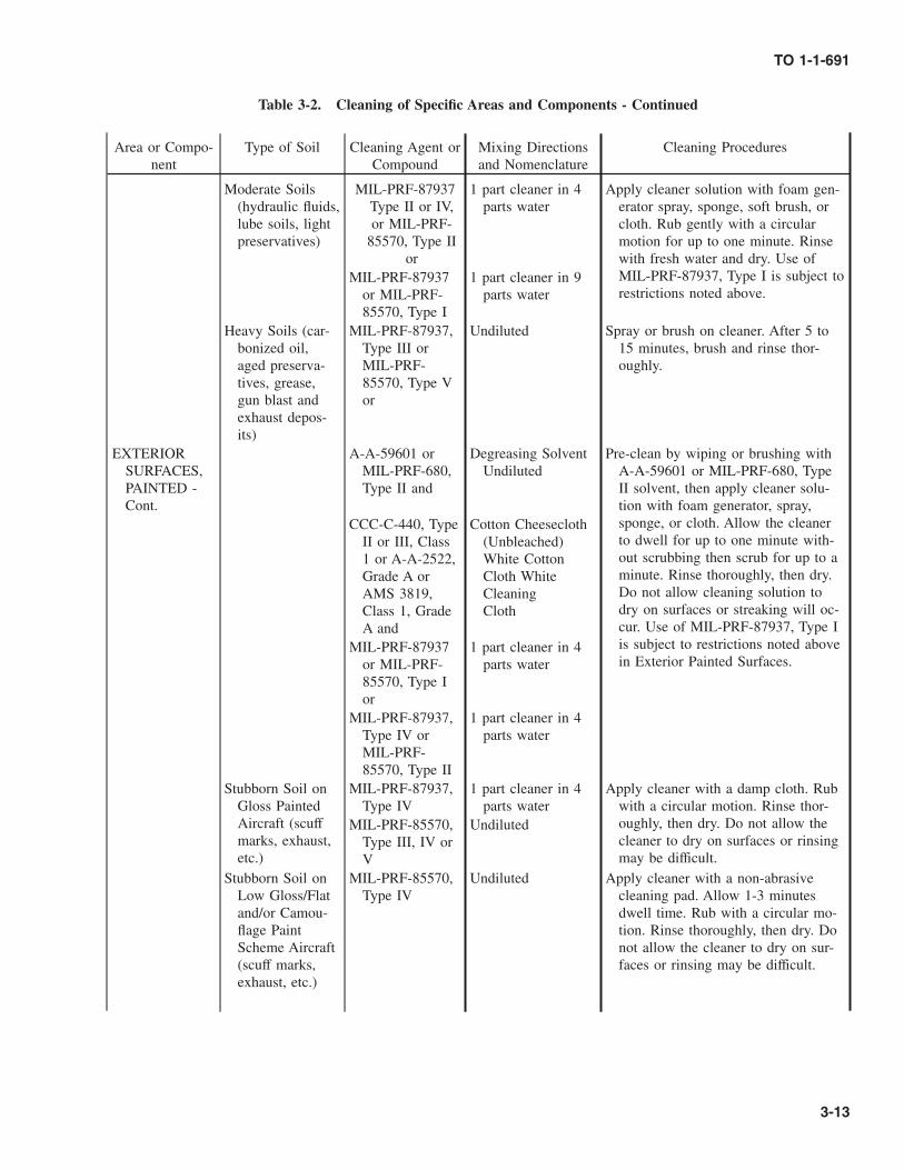
Table 3-2. Cleaning of Specific Areas and Components - Continued
Area or Compo-nent
Type of Soil Cleaning Agent orCompound
Mixing Directionsand Nomenclature
Cleaning Procedures
Moderate Soils(hydraulic fluids,lube soils, lightpreservatives)
MIL-PRF-87937Type II or IV,or MIL-PRF-
85570, Type IIor
1 part cleaner in 4parts water
Apply cleaner solution with foam gen-erator spray, sponge, soft brush, orcloth. Rub gently with a circularmotion for up to one minute. Rinsewith fresh water and dry. Use ofMIL-PRF-87937, Type I is subject torestrictions noted above.
MIL-PRF-87937or MIL-PRF-85570, Type I
1 part cleaner in 9parts water
Heavy Soils (car-bonized oil,aged preserva-tives, grease,gun blast andexhaust depos-its)
MIL-PRF-87937,Type III orMIL-PRF-85570, Type Vor
Undiluted Spray or brush on cleaner. After 5 to15 minutes, brush and rinse thor-oughly.
EXTERIORSURFACES,PAINTED -Cont.
A-A-59601 orMIL-PRF-680,Type II and
Degreasing SolventUndiluted
Pre-clean by wiping or brushing withA-A-59601 or MIL-PRF-680, TypeII solvent, then apply cleaner solu-tion with foam generator, spray,sponge, or cloth. Allow the cleanerto dwell for up to one minute with-out scrubbing then scrub for up to aminute. Rinse thoroughly, then dry.Do not allow cleaning solution todry on surfaces or streaking will oc-cur. Use of MIL-PRF-87937, Type Iis subject to restrictions noted abovein Exterior Painted Surfaces.
CCC-C-440, TypeII or III, Class1 or A-A-2522,Grade A orAMS 3819,Class 1, GradeA and
Cotton Cheesecloth(Unbleached)White CottonCloth WhiteCleaningCloth
MIL-PRF-87937or MIL-PRF-85570, Type Ior
1 part cleaner in 4parts water
MIL-PRF-87937,Type IV orMIL-PRF-85570, Type II
1 part cleaner in 4parts water
Stubborn Soil onGloss PaintedAircraft (scuffmarks, exhaust,etc.)
MIL-PRF-87937,Type IV
1 part cleaner in 4parts water
Apply cleaner with a damp cloth. Rubwith a circular motion. Rinse thor-oughly, then dry. Do not allow thecleaner to dry on surfaces or rinsingmay be difficult.
MIL-PRF-85570,Type III, IV orV
Undiluted
Stubborn Soil onLow Gloss/Flatand/or Camou-flage PaintScheme Aircraft(scuff marks,exhaust, etc.)
MIL-PRF-85570,Type IV
Undiluted Apply cleaner with a non-abrasivecleaning pad. Allow 1-3 minutesdwell time. Rub with a circular mo-tion. Rinse thoroughly, then dry. Donot allow the cleaner to dry on sur-faces or rinsing may be difficult.
TO 1-1-691
3-13

Table 3-2. Cleaning of Specific Areas and Components - Continued
Area or Compo-nent
Type of Soil Cleaning Agent orCompound
Mixing Directionsand Nomenclature
Cleaning Procedures
Wear rubber gloves, chemical or splash proof goggles, and water resistant boots duringcleaning operations using MIL-PRF-87937 or MIL-PRF-85570 cleaning compounds. Ifcleaner is splashed in eyes, rinse thoroughly with fresh water for 15 minutes and report tomedical facility. Remove clothing saturated with cleaning solution immediately and flushexposed skin with fresh water.
Do not allow MIL-PRF-87937 or MIL-PRF-85570, Type I cleaning solutions to contactcanopy, window, or windshield/windscreen transparent plastic panels as they may causecrazing.
EXTERIORSURFACES,UNPAINTED
Gunblast residues,carbonized ex-haust residues
MIL-PRF-87937or MIL-PRF-85570, Type Ior
1 part cleaner in 4parts water
Wet surface with fresh water. Applycleaning solution and scrub brisklywith A-A-58054 Type I, Grade A orB abrasive mat. Rinse with freshwater and dry. Use of MIL-PRF-87937, Type I is subject to restric-tions noted above in Exterior PaintedSurfaces.
MIL-PRF-87937,Type III orMIL-PRF-85570, Type IVor V
Undiluted
• Wear rubber gloves, chemical or splash proof goggles, and water resistant boots duringcleaning operations using MIL-PRF-87937 or MIL-PRF-85570 cleaning compounds. Ifcleaner is splashed in eyes, rinse thoroughly with fresh water for 15 minutes and reportto medical facility. Remove clothing saturated with cleaning solution immediately andflush exposed skin with fresh water.
• When using Ammonium Hydroxide (Ammonia), do not breathe vapors and avoid skincontact. Wash immediately if spilled on skin.
• When using Ammonium Hydroxide (Ammonia), do not allow any solutions to contactaircraft wiring. Flush immediately with fresh water if spillage occurs.
• Avoid use of compressed air to clean electronic equipment. Do not use abrasives in ra-dome compartments.
TO 1-1-691
3-14

Table 3-2. Cleaning of Specific Areas and Components - Continued
Area or Compo-nent
Type of Soil Cleaning Agent orCompound
Mixing Directionsand Nomenclature
Cleaning Procedures
INTERIOR AR-EAS
Lavatories Urine residue A-A-59370 Ammonium Hydrox-ide (Ammonia) 1part in 20 partswater
Sponge with a solution of ammo-nium hydroxide (Ammonia).Flush with fresh water or wetsurface with sodium bicarbonatesolution, allow to dry, and rinsewith fresh water. Dry with aclean cloth.
ASTM D 928 Sodium Bicarbonate,6 oz to 1 gallonof fresh water
USDA Reg 100-12-1
Germicidal Tablets Use germicidal tables as toilet andurinal deodorants.
All types of soilson lavatory sur-faces
O-D-1435; A-A-1439; or SAEAMS 1453
Mix per manf. in-structions
Pour solution into toilets, urinals,and latrine buckets. Scrub with abrush, and rinse with fresh water.Sponge all other surfaces withthe solution, sponge area withfresh water; and wipe dry.
Floor and Deck Dirt, debris MIL-PRF-87937,Type II or IVor MIL-PRF-85570, Type II(Preferred) or
1 part cleaner in 9parts water
Remove loose dirt with vacuumcleaner. Wipe with cleaning com-pound, and rinse with fresh wa-ter. Use of MIL-PRF-87937, TypeI is subject to restrictions notedabove in Exterior Painted Sur-faces.
MIL-PRF-87937,or MIL-PRF-85570, Type I(Alternate)
1 part cleaner in 16parts water
Radome andEquipmentCompartment(interior)
Dust, dirt, oil, anddebris
MIL-PRF-87937,Type II or IVor MIL-PRF-85570 Type IIand
1 part cleaner in 16parts water
Remove loose dirt with a vacuumcleaner. Wipe fiberglass and othersurfaces with a cloth wet withcleaning solution and rinse withcloth wet with fresh water. Drywith a clean cloth.CCC-C-440, Type
I or II, Class 1or A-A-59323,Type II or AMS3819, Class 1,Grade A or B
Cotton Cheesecloth(Unbleached)CleaningCloth, Low lintWhite CleaningCloth
Cockpit Interior Dust, dirt, mud,and light debris
MIL-PRF-87937,Type II or IVor MIL-PRF-85570, Type IIand
1 part cleaner in 9parts water
Loosen any accumulations of mudon control pedals, floors, or othercockpit equipment with brush andremove with vacuum cleaner.Wipe with cloth wet with clean-ing solution and follow with acloth wet with fresh water. Drywith a clean cloth.
A-A-50129 Cloth, Flannel
EnvironmentalControl Duct-ing
Light debris, dust,and grime
MIL-PRF-87937,Type II or IVor MIL-PRF-85570, Type II
1 part cleaner in 9parts water
Refer to applicable maintenancemanuals.
TO 1-1-691
Change 1 3-15
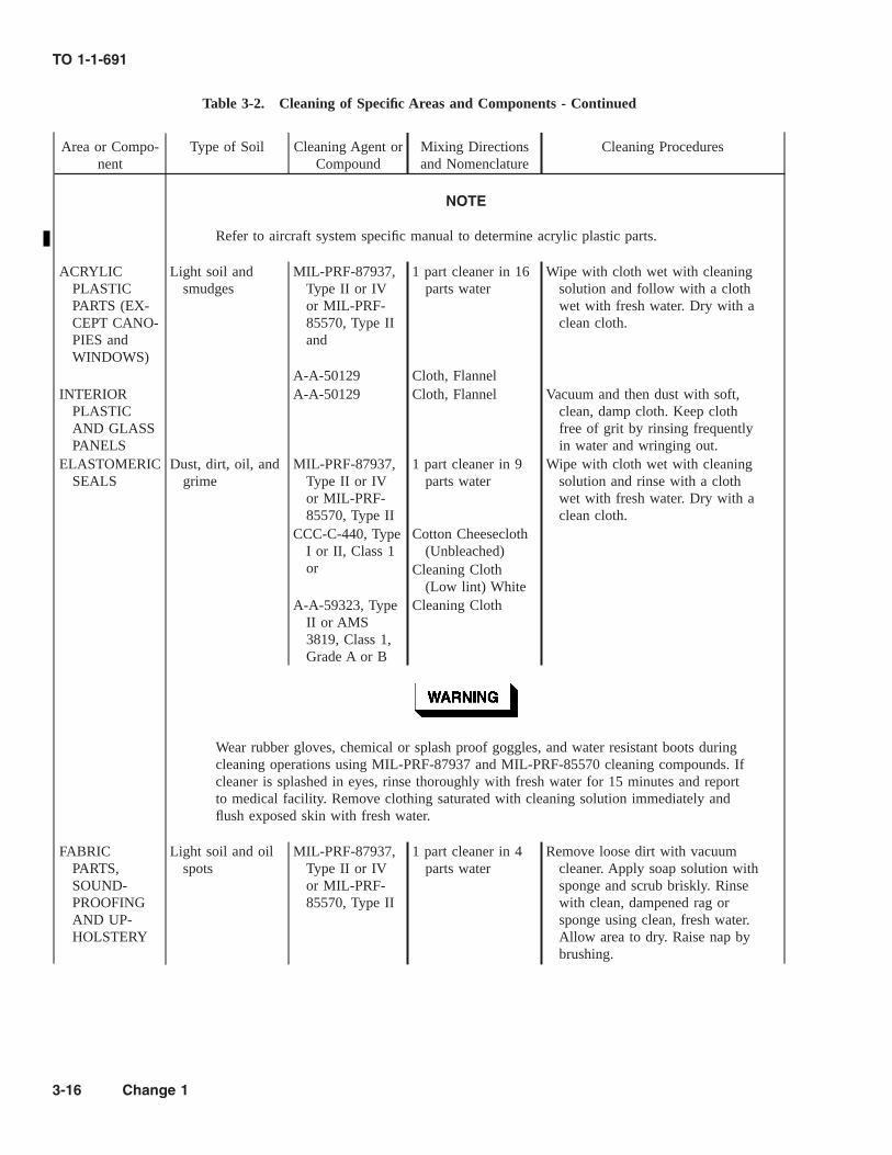
Table 3-2. Cleaning of Specific Areas and Components - Continued
Area or Compo-nent
Type of Soil Cleaning Agent orCompound
Mixing Directionsand Nomenclature
Cleaning Procedures
NOTE
Refer to aircraft system specific manual to determine acrylic plastic parts.
ACRYLICPLASTICPARTS (EX-CEPT CANO-PIES andWINDOWS)
Light soil andsmudges
MIL-PRF-87937,Type II or IVor MIL-PRF-85570, Type IIand
1 part cleaner in 16parts water
Wipe with cloth wet with cleaningsolution and follow with a clothwet with fresh water. Dry with aclean cloth.
A-A-50129 Cloth, FlannelINTERIOR
PLASTICAND GLASSPANELS
A-A-50129 Cloth, Flannel Vacuum and then dust with soft,clean, damp cloth. Keep clothfree of grit by rinsing frequentlyin water and wringing out.
ELASTOMERICSEALS
Dust, dirt, oil, andgrime
MIL-PRF-87937,Type II or IVor MIL-PRF-85570, Type II
1 part cleaner in 9parts water
Wipe with cloth wet with cleaningsolution and rinse with a clothwet with fresh water. Dry with aclean cloth.
CCC-C-440, TypeI or II, Class 1or
Cotton Cheesecloth(Unbleached)
Cleaning Cloth(Low lint) White
A-A-59323, TypeII or AMS3819, Class 1,Grade A or B
Cleaning Cloth
Wear rubber gloves, chemical or splash proof goggles, and water resistant boots duringcleaning operations using MIL-PRF-87937 and MIL-PRF-85570 cleaning compounds. Ifcleaner is splashed in eyes, rinse thoroughly with fresh water for 15 minutes and reportto medical facility. Remove clothing saturated with cleaning solution immediately andflush exposed skin with fresh water.
FABRICPARTS,SOUND-PROOFINGAND UP-HOLSTERY
Light soil and oilspots
MIL-PRF-87937,Type II or IVor MIL-PRF-85570, Type II
1 part cleaner in 4parts water
Remove loose dirt with vacuumcleaner. Apply soap solution withsponge and scrub briskly. Rinsewith clean, dampened rag orsponge using clean, fresh water.Allow area to dry. Raise nap bybrushing.
TO 1-1-691
3-16 Change 1

Table 3-2. Cleaning of Specific Areas and Components - Continued
Area or Compo-nent
Type of Soil Cleaning Agent orCompound
Mixing Directionsand Nomenclature
Cleaning Procedures
Do not use synthetic wiping cloths with flammable solvents, such as TT-N-95 aliphaticnaphtha.
Refer to aircraft system specific manual to determine cleaning procedures for aircraftcanopies. In addition, refer to TO 1-1A-12. Remove rings, watches, or other hard ob-jects from hands and wrists before washing transparent plastics. Personnel must alsotake precautions to prevent buttons, badges, or other hard objects from scratching sur-faces. Do not use hard, dirty, or gritty cloths in cleaning and polishing transparent plas-tics. Wiping with such cloths can mar and scratch plastic surfaces. Do not use anychemical compounds unless specifically authorized for cleaning plastics. Do not rub dryplastic panels with dry cloth, which might scratch surface or create electrostatic chargethat attracts dust.
CANOPY EX-TERIOR,PLASTICAND GLASSWINDOWAND WIND-SHIELD/WIND-SCREENPANELS
Dust, dirt grime,salt spray,
P-P-560 and Plastic Polish Com-pound
Rub gently with bare hands orclean cloth while flushing withfresh water to remove loose dirt.Apply polishing compound witha soft, clean cloth and rub usinga circular motion until clean. Pol-ish with another soft, clean cloth.
A-A-50129 Cloth, FlannelOil, grease TT-N-95 and Aliphatic Naphtha Apply naphtha with soft, clean
cloth. Blot gently; solvent willevaporate and not leave a film.
P-P-560 and Plastic Polish Com-pound
Apply polishing compound. Rubusing a circular motion untilclean and polish with anothersoft, clean cloth.
A-A-50129 Cloth, Flannel
TO 1-1-691
Change 1 3-17

Table 3-2. Cleaning of Specific Areas and Components - Continued
Area or Compo-nent
Type of Soil Cleaning Agent orCompound
Mixing Directionsand Nomenclature
Cleaning Procedures
• Open all circuit breakers associated with battery power (refer to applicable systemspecific maintenance manuals) prior to application of MIL-PRF-680 Degreasing Sol-vent or A-A-59601 Dry Cleaning and Degreasing Solvent, PD680.
• Both of these solvents are combustible. Keep away from open flames. Use in a well-ventilated area. Wear rubber gloves and chemical or splash proof goggles. Avoid skincontact. Consult the local safety office regarding respiratory protection.
Do not use excessive cleaning solvent on control cables. Solvent will remove internallubricant.
CONTROLCABLES
Dust, dirt oil,grease
A-A-59601 orMIL-PRF-680,Type II and
Degreasing Solvent Wipe with clean cloth dampenedwith solvent. Apply MIL-PRF-81309, Type II water displacingCPC to cables, and recoat cableswith MIL-PRF-16173, Grade 4CPC.
MIL-PRF-81309,Type II and
Water Displacing,CPC
MIL-PRF-16173,Grade 4
CPC
Wipe away from seal areas to preclude collection of soil at seal junction areas. Makesure piston surface is clean and completely lubricated but not dripping. If piston is dry,telescoping action of strut will force gritty particles into cylinder causing leaks andeventual failure. Do not use aerosol type cleaning fluids on hydraulic systems.
LANDINGGEAR EX-POSED PIS-TON SUR-FACES
Sand, dirt, saltdeposits, andother foreignparticles
MIL-PRF-83282 Hydraulic Fluid, Clean exposed surfaces with cleancloth dampened with hydraulicfluid. Take care not to scratch thesurface. Wipe away from seals,not toward them.
CCC-C-440, TypeI or II, Class 1or A-A-59323,Type II or AMS3819, Class 1,Grade A or B
Cotton Cheesecloth(Unbleached)Cleaning Cloth(Low lint) Clean-ing Cloth
TO 1-1-691
3-18 Change 1

Table 3-2. Cleaning of Specific Areas and Components - Continued
Area or Compo-nent
Type of Soil Cleaning Agent orCompound
Mixing Directionsand Nomenclature
Cleaning Procedures
• Open all circuit breakers associated with battery power (refer to applicable systemspecific maintenance manuals) prior to application of MIL-PRF-680 Degreasing Sol-vent or A-A-59601 Dry Cleaning and Degreasing Solvent, P-D-680.
• Both of these solvents are combustible. Keep away from open flames. Use in a well-ventilated area. Wear rubber gloves and chemical or splash proof goggles. Avoid skincontact. Consult the local safety office regarding respiratory protection.
Do not use MIL-PRF-16173, Grade 4 or MIL-DTL-85054 on micro-switches or exposedpiston rod surfaces.
DOORS, LINK-AGES, CYL-INDERS
Dust, dirt, oil,grease
A-A-59601 orMIL-PRF-680,Type II
Degreasing Solvent Brush surfaces as necessary withsolvent. Cover rod ends andsprings with MIL-PRF-16173,Grade 4 CPC. Where lubricationis not required, MIL-DTL-85054CPC may be applied.
MIL-PRF-16173,Grade 4 or
CPC
MIL-DTL-85054 CPCWHEELS AND
BRAKESOil, grease, dirt,
sand, and otherforeign matter
For cleaning wheels and brakesreference TO 4W-1-61 and 4B-1-32.
AF Drawing #9825019 speci-fied materials
Dilute and/or mixper manufacturer’sinstructions
Use only those cleaners listed inthe most current revision of AFDrawing No. 9825019. Place offaircraft parts in the AqueousParts Washer and run through thecomplete wash, rinse, and drycycle.
TO 1-1-691
Change 1 3-19

Table 3-2. Cleaning of Specific Areas and Components - Continued
Area or Compo-nent
Type of Soil Cleaning Agent orCompound
Mixing Directionsand Nomenclature
Cleaning Procedures
• Open all circuit breakers associated with battery power (refer to applicable systemspecific maintenance manuals) prior to application of MIL-PRF-680 Degreasing Sol-vent or A-A-59601 Dry Cleaning and Degreasing Solvent, PD680.
• Both of these solvents are combustible. Use in a well-ventilated area. Keep it awayfrom open flames. Avoid contact with skin.
• Wear rubber gloves, chemical or splash proof goggles, and water resistant boots dur-ing cleaning operations using MIL-PRF-87937, MIL-PRF-85570, or MIL-C-43616cleaning compounds. If cleaner is splashed in eyes, rinse thoroughly with fresh waterfor 15 minutes and report to medical facility. Remove clothing saturated with clean-ing solution immediately and flush exposed skin with fresh water.
Protect tires from contact with degreasing solvents or cleaning solutions.
LANDINGGEAR(OTHERTHAN EX-POSED PIS-TON AREA)AND WHEELWELLS
Dirt, grease, hy-draulic fluid, etc.
MIL-PRF-87937,Type III orMIL-PRF-85570, Type Vor
Undiluted Apply thixotropic gel Type III orType V cleaner with spray orbrush and allow a 5-15 minutedwell. Brush, if necessary, andrinse thoroughly with fresh water.Repeat rinsing with brushing toremove cleaner residues.
A-A-59601 orMIL-PRF-680,Type II or III
Undiluted De-greasing Solvent
Alternate procedure: Brush on sol-vent to loosen stubborn soil.
MIL-C-43616,Class 1 or MIL-PRF-85570,Type I
1 part cleaner in 4parts water
Apply MIL-C-43616, Class 1, MIL-PRF-85570, Type I or MIL-PRF-87937, Type I cleaning solution,brush, and rinse. Omit solventpre-soak if desired. Use of MIL-PRF-87937, Type I may be re-stricted as noted above in Exte-rior Painted Surfaces.
TO 1-1-691
3-20 Change 1

Table 3-2. Cleaning of Specific Areas and Components - Continued
Area or Compo-nent
Type of Soil Cleaning Agent orCompound
Mixing Directionsand Nomenclature
Cleaning Procedures
Before cleaning electrical and avionic equipment, make sure electrical power is discon-nected. Injury and death may otherwise result.
Avoid use of compressed air in electronic compartments because air can force dust, dirt,and other foreign materials into components or equipment and cause damage.
ELECTRICALCONNEC-TORS ANDAVIONICCOMPO-NENTS
Dust, dirt, lint, andother loose for-eign matter,grease, oilsmudges, lighttarnish, corro-sion, or fungi
Refer to TO 1-1-689-1, TO 1-1-689-3, and TO 1-1-689-5.
• Open all circuit breakers associated with battery power (refer to applicable systemspecific maintenance manuals) prior to application of TT-I-735 isopropyl alcohol.
• Do not use synthetic wiping cloths with flammable solvents such as TT-I-735 isopro-pyl alcohol.
ORGANIC MA-TERIALS;MILDEW,MOLD, FUN-GUS, ETC
Fungi, mold, mil-dew, etc.
TT-I-735 Isopropyl Alcohol Wipe with clean cloth wet withisopropyl alcohol. To preventrecurring fungus growth, keeparea dry and clean. For treatmentof fungus in fuel systems, contactthe appropriate aircraft SPDand/or missile or equipmentSPM.
CCC-C-440, TypeI or II, Class 1or A-A-59323,Type II or AMS3819, Class 1,Grade A or B
Cotton CheeseclothCleaning ClothLow lint CleaningCloth
OXYGENLINES (EX-TERIORSURFACES)
Oil, grease Refer to system specific maintenance manuals.
TO 1-1-691
Change 1 3-21

Table 3-2. Cleaning of Specific Areas and Components - Continued
Area or Compo-nent
Type of Soil Cleaning Agent orCompound
Mixing Directionsand Nomenclature
Cleaning Procedures
Wear rubber gloves, chemical or splash proof goggles, and water resistant boots duringcleaning operations using MIL-PRF-87937 or MIL-PRF-85570 cleaning compounds. Ifcleaner is splashed in eyes, rinse thoroughly with fresh water for 15 minutes and reportto medical facility. Remove clothing saturated with cleaning solution immediately andflush exposed skin with fresh water.
RELIEF TUBES(EXTERIOR)
Human waste(urine)
MIL-PRF-87937,Type II or IVor MIL-PRF-85570, Type II
1 part cleaner in 9parts water
Wash thoroughly with solution us-ing a soft, bristle brush, thenrinse thoroughly with fresh waterand wipe dry.
Wear rubber gloves, chemical or splash proof goggles, and water resistant boots duringcleaning operations using MIL-PRF-87937 or MIL-PRF-85570 cleaning compounds. Ifcleaner is splashed in eyes, rinse thoroughly with fresh water for 15 minutes and reportto medical facility. Remove clothing saturated with cleaning solution immediately andflush exposed skin with fresh water.
Do not use strong alkaline cleaners or highly abrasive compounds when cleaning rotortip cap areas. Refer to systems specific technical orders for specific cleaninginstructions.
HELICOPTERAND PRO-PELLERBLADES
Grime, oil, grease,exhaust stains
MIL-PRF-87937,Type IV orMIL-PRF-85570, Type II
1 part cleaner in 9parts water
Apply cleaning solution with acleaning pad or brush and agitate.Rinse with fresh water and wipedry.
A-A-3100 Cleaning PadHELICOPTER
CARGO ANDRESCUEHOISTCABLE, ANDEND FIT-TINGS
Salt, and salt water MIL-PRF-16173,Grade 3 orMIL-PRF-81309, Type IIor MIL-L-87177, Type I,Grade B
Water DisplacingCorrosion Preven-tive Compound
Flush thoroughly with fresh water.Blow dry with clean, compressedair or thoroughly dry with a cot-ton cloth. Spray with MIL-PRF-16173, Grade 3; MIL-PRF-81309, Type II; or MIL-L-87177,Type I, Grade B compound as itis being rewound. Remove excesswith clean dry cloth.A-A-50129 Cloth, Flannel
TO 1-1-691
3-22 Change 1

Table 3-2. Cleaning of Specific Areas and Components - Continued
Area or Compo-nent
Type of Soil Cleaning Agent orCompound
Mixing Directionsand Nomenclature
Cleaning Procedures
Wear rubber gloves, chemical or splash proof goggles, and water resistant boots duringcleaning operations using MIL-C-43616, MIL-PRF-87937, or MIL-PRF-85570 cleaningcompounds. If cleaner is splashed in eyes, rinse thoroughly with fresh water for 15 min-utes and report to medical facility. Remove clothing saturated with cleaning solutionimmediately and flush exposed skin with fresh water.
HELICOPTERCARGO ANDRESCUEHOISTDRUM
Salt, and salt water MIL-PRF-87937or MIL-PRF-85570, Type Ior MIL-C-43616, Class 1
1 part cleaner in 9parts water
Rinse with fresh water. Applycleaning solution and scrub witha clean cloth or sponge. Rinsewith clean water. Blow dry withclean, compressed air or dry witha clean, dry cloth. Use of MIL-PRF-87937, Type I may be re-stricted as noted above in Exte-rior Painted Surfaces.
Wear rubber gloves, chemical or splash proof goggles, and water resistant boots duringcleaning operations using MIL-PRF-87937 or MIL-PRF-85570 cleaning compounds. Ifcleaner is splashed in eyes, rinse thoroughly with fresh water for 15 minutes and reportto medical facility. Remove clothing saturated with cleaning solution immediately andflush exposed skin with fresh water.
HELICOPTERRESCUESLING
Salt, and salt water MIL-PRF-87937,Type IV orMIL-PRF-85570, Type II
1 part cleaner in 9parts water
Rinse with fresh water. Applycleaning solution with sponge orclean cloth. Rinse thoroughlywith fresh water. Blow dry withclean compressed air or suspendand allow to dry. If suspended todry, ensure water will drain awayfrom the buckle.
TO 1-1-691
Change 1 3-23

Table 3-2. Cleaning of Specific Areas and Components - Continued
Area or Compo-nent
Type of Soil Cleaning Agent orCompound
Mixing Directionsand Nomenclature
Cleaning Procedures
• Open all circuit breakers associated with battery power (refer to applicable systemspecific maintenance manuals) prior to application of MIL-PRF-680 Degreasing Sol-vent or A-A-59601 Dry Cleaning and Degreasing Solvent, PD680.
• Both of these solvents are combustible. Keep away from open flames. Use in a well-ventilated area. Wear rubber gloves and chemical or splash proof goggles. Avoid skincontact. Consult the local safety office regarding respiratory protection.
ENGINES, RE-CIPROCAT-ING
Oxidized oil, dust,carbon, salt de-posits
A-A-59601 orMIL-PRF-680,Type II and
Degreasing Solvent Apply solvent with cleaning clothor brush. Repeat application anddry. Collect solvent runoff anddispose in accordance with localregulations.
CCC-C-440, TypeI or II, Class 1or
Cotton Cheesecloth(Unbleached)
A-A-59323, TypeII or AMS3819, Class 1,Grade A or B
Cleaning Cloth LowLint CleaningCloth
TO 1-1-691
3-24 Change 1

Table 3-2. Cleaning of Specific Areas and Components - Continued
Area or Compo-nent
Type of Soil Cleaning Agent orCompound
Mixing Directionsand Nomenclature
Cleaning Procedures
Wear rubber gloves, chemical or splash proof goggles, protective wet weather clothingwhere necessary, and water resistant boots during cleaning operations using cleaningcompound MIL-PRF-85704, Types II or II RTU. If cleaner is splashed in eyes, rinsethoroughly with fresh water for 15 minutes and report to medical facility. Removeclothing saturated with cleaning solution immediately and flush exposed areas with freshwater.
• Use only MIL-PRF-85704 cleaning compound for cleaning turbine engine gas paths.Prepare aircraft in accordance with applicable system specific maintenance manualsand/or maintenance work cards. In case of conflict, the manuals and/or work cardstake precedence over the following instructions.
• MIL-PRF-85704, Type I gas path cleaners typically contain 30 to 60 percent solvent.When diluted (1 part cleaner to 4 parts water), some products are above the 10%solvent limit; and most contain enough naphthalene to cause wash rack runoff to ex-ceed the discharge permit limits. The current substitute is MIL-PRF-85704, Type II, awater-base product that contains less than 10 percent solvent in the concentrate. Thismaterial shall be used at the same dilution ratio while using the same starter crankedengine wash procedures, which are currently approved in aircraft engine manuals.MIL-PRF-85704, Type II RTU is ready to use (does not require dilution, but required5 times the storage space since it is already diluted with water).
GAS TURBINEENGINEINTER-IOR(GAS PATH)
Oxidized oil, dust,carbon, salt de-posits
MIL-PRF-85704,Type II or
1 part cleaner in 4parts water
Use in accordance with applicableengine maintenance manual in-structions. Dispose of wastecleaner in accordance with localregulations.
MIL-PRF-85704,Type II RTU
Do not dilute, this isa ready mix form
TO 1-1-691
Change 1 3-25

Table 3-2. Cleaning of Specific Areas and Components - Continued
Area or Compo-nent
Type of Soil Cleaning Agent orCompound
Mixing Directionsand Nomenclature
Cleaning Procedures
Wear rubber gloves, chemical or splash proof goggles, and water resistant boots duringcleaning operations using MIL-PRF-87937, MIL-PRF-85570, MIL-C-43616, or MIL-PRF-85704, Types I or II cleaning compounds. If cleaner is splashed in eyes, rinse thor-oughly with fresh water for 15 minutes and report to medical facility. Remove clothingsaturated with cleaning solution immediately and flush exposed skin with fresh water.
Prepare aircraft in accordance with applicable system specific maintenance manualsand/or maintenance work cards. In case of conflict, the manuals and/or work cards takeprecedence over the following instructions.
GAS TURBINEENGINE EX-TERIOR, EN-GINE BAYAND EN-GINE BAYDOORS
Oxidized oil, dust,carbon, salt de-posits
MIL-C-43616,Class 1 or MIL-PRF-85704,Type I or II or
1 part cleaner in 4parts water
Apply mixed cleaning solutions(MIL-C-43616, Class 1; MIL-PRF-85704, Type I or II; MIL-PRF-87937, Type IV; or MIL-PRF-85570, Type II) or the pre-mixed cleaners (MIL-C-43616,Class 1A or MIL-PRF-85704,Type II RTU) with a brush,scrub, then rinse with fresh water.When using the MIL-PRF-87937,Type III or MIL-PRF-85570,Type V, apply the undiluted con-centrate with a brush, allowcleaner to remain on surface for5 minutes, then brush and rinsethoroughly. Dispose of wastecleaners in accordance with localdirectives.
MIL-C-43616,Class 1A or
Aerosol Can
MIL-PRF-85704,Type II RTU or
Do not dilute, this isa ready mix form
MIL-PRF-87937,Type IV orMIL-PRF-85570, Type IIor
1 part cleaner in 4parts water
MIL-PRF-87937,Type III orMIL-PRF-85704, Type V
Undiluted concen-trate
TO 1-1-691
3-26 Change 1

Table 3-2. Cleaning of Specific Areas and Components - Continued
Area or Compo-nent
Type of Soil Cleaning Agent orCompound
Mixing Directionsand Nomenclature
Cleaning Procedures
Never use a wire brush to clean a battery or a battery area. Wear rubber gloves, a rub-ber apron, and protective goggle when handling batteries.
• Nickel-cadmium batteries must not be exposed to acid or acid vapors. Battery elec-trolytes are extremely corrosive. Spilled electrolyte shall be removed immediately.Refer to applicable system specific aircraft, missile, or equipment manuals for batterytype.
• Fumes from overheated electrolyte will spread to adjacent areas, causing rapid corro-sion on unprotected surfaces.
NOTE
Refer to chapter 7 for additional instructions.
Battery Com-partments
Nickel-cadmiumbattery electro-lyte deposits(potassium hy-droxide solution)
A-A-59282 or Boric Acid Remove spilled electrolyte immedi-ately by flushing with fresh wa-ter. Spray the contaminated areawith Bromothymol Blue solution(Refer to Chapter 7). Neutralizethe area by sponging or sprayinggenerously with boric acid orsodium phosphate solution. Brushwith a fiber bristle brush andflush with fresh water. Reapplythe Bromothymol Blue solutionto determine if all the electrolytehas been neutralized. Retreat areaas required and rinse. Dry withclean wiping cloths. Keep thecell vents open, but do not allowany solutions to enter the cells.Preserve compartment with MIL-PRF-81309, Type II, Class 1 or 2or MIL-L-87177, Type I or II ,Grade B CPC. Do not paint orpreserve batteries.
ANSI/AWWA B504
Monobasic sodiumphosphate
Mix either material6 oz in 1 gallonwater
MIL-PRF-81309,Type II, Class 1or 2, or MIL-L-87177, Type Ior II, Grade B
Water DisplacingCPC
TO 1-1-691
Change 1 3-27

Table 3-2. Cleaning of Specific Areas and Components - Continued
Area or Compo-nent
Type of Soil Cleaning Agent orCompound
Mixing Directionsand Nomenclature
Cleaning Procedures
Lead-acid batteryelectrolyte de-posits (sulfuricacid solution)
ASTM D 928 Sodium bicarbonate,6 oz in 1 gallonwater
Remove spilled electrolyte immedi-ately by flushing with fresh wa-ter. Spray the contaminated areawith Litmus solution (Refer toChapter 7). Neutralize the area bysponging or spraying with so-dium bicarbonate solution. Applygenerously until bubbling stopsand the Litmus solution turnsblue. Let it stay on the surfacefor 5 minutes, but do not allowto dry. Brush with a fiber bristlebrush, then flush with fresh wa-ter. Reapply the Litmus solutionto determine if all the electrolytehas been neutralized. Retreat thearea as required and rinse. Drywith clean wiping cloths. Keepthe cell vents open but do notallow any solutions to enter thecells. Preserve compartment withMIL-PRF-81309, Type II, Class 1or 2, or MIL-L-87177, Type I orII, Grade B CPC. Do not paint orpreserve batteries.
MIL-PRF-81309,Type II, Class 1or 2, or MIL-L-87177, Type Ior II, Grade B
Water DisplacingCPC
• Wear rubber gloves, chemical or splash proof goggles, and water resistant boots dur-ing cleaning operations using MIL-PRF-87937 or MIL-PRF-85570 cleaning com-pounds. If cleaner is splashed in eyes, rinse thoroughly with fresh water for 15 min-utes and report to medical facility. Remove clothing saturated with cleaning solutionimmediately and flush exposed skin with fresh water.
• A-A-59601, Type III Dry Cleaning and Degreasing Solvent, PD680 and MIL-PRF-680, Type III Degreasing Solvent are non-combustible, but can still burn if exposedto flames. Use in a confined area is allowed, but this area should still be well-ventilated. Keep away from open flames. Avoid contact with skin.
BILGE AREAS Hydraulic fluid,water, dirt, me-tallic debris
MIL-PRF-87937,Type II or IV,or MIL-PRF-85570, Type IIor
1 part cleaner in 9parts water
Vacuum clean liquids and debris.Wipe area with a sponge damp-ened in cleaning solution. Rinseby sponging with fresh water.Wipe dry with a clean cloth.
MIL-PRF-87937or MIL-PRF-85570, Type Ior
1 part cleaner in 16parts water
Use of MIL-PRF-87937, Type Imay be restricted as noted abovein Exterior Painted Surfaces.
TO 1-1-691
3-28 Change 1

Table 3-2. Cleaning of Specific Areas and Components - Continued
Area or Compo-nent
Type of Soil Cleaning Agent orCompound
Mixing Directionsand Nomenclature
Cleaning Procedures
A-A-59601 orMIL-PRF-680,Type III
Degreasing Solvent Wipe with cloth dampened withsolvent. Wipe dry with a cleancloth.
Algae contamina-tion
MIL-PRF-87937,Type IV, orMIL-PRF-85570, Type IIor
1 part cleaner in 4parts water
Mix cleaner and water in a pumpspray bottle. Spray mixture oncontaminated area and allow it todwell at least 2 minutes. Wipe offwith a sponge and dry with aclean cloth. Use of MIL-PRF-87937, Type I may be restrictedas noted above in ExteriorPainted Surfaces.
MIL-PRF-87937or MIL-PRF-85570, Type Ior
1 part cleaner in 9parts water
MIL-PRF-87937,Type III orMIL-PRF-85570, Type V
Undiluted concen-trate
OPTICALGLASS
Dust, grease, oil A-A-59199 and Optical cleaner Spray cleaner onto flannel and care-fully wipe the lens or other opti-cal surface. Wipe dry with cleanflannel cloth.A-A-50129 Cloth, Flannel
EJECTIONSEATS
• Application of corrosion preventive compounds (CPC’s) or paints to certain areas ofejection seats could prevent or restrict seat operation. Specific ejection seat instruc-tions must be followed carefully.
• See system specific ejection seat maintenance manuals and SPM instructions for cor-rosion prevention and control and lubrication of ejection seats.
REMOVABLEMETALFUEL TANKS
Fuel residues,grease, and ex-haust deposits
MIL-PRF-85570 Use MIL-PRF-85570 detergent inaccordance with procedures insystems specific fuel tank manu-als.
TO 1-1-691
Change 1 3-28.1/(3-28.2 blank)


3.4 CLEANING EQUIPMENT.
• High pressure wash equipment which devel-ops more than 175 PSI nozzle pressure shallnot be used to apply cleaning compoundsunless specifically authorized by the aircraftSPD and/or the missile or equipment SPM.
• High pressure wash equipment shall never beused on aircraft landing gear and components,wheels, and brakes as they can force lubricantsout of bearings and attach points, and causecorrosion and wear problems.
NOTE
• Use only cleaning materials and equipmentauthorized and described in this manual. Ex-perimentation with unauthorized cleaners maydamage aircraft, missiles, and equipment thusreducing reliability and increasing mainte-nance costs.
• Cleaning equipment specific to one type ofaircraft, missile, or piece of equipment is notcovered by this manual. Approved equipmentfor general cleaning is discussed in thismanual, and ordering information is presentedin Appendix B of this manual. General oper-ating instructions are in Paragraph 3.4.1through 3.4.9. See specific equipment operat-ing manuals for detailed equipment operatinginstructions.
3.4.1 High Pressure/Hot Water Wash Equipment. Ifapproved by the aircraft SPD and/or the equipment SPM,high pressure/hot water wash equipment can be used forgeneral purpose cleaning of aircraft, support equipment, andvehicles. These machines can deliver four gallons per minuteof water and/or cleaning solution at a temperature of 210° Fand a pressure of 3000 PSI at the attach points on the machinefor each output hose. These machines shall be operated perthese instructions and the directions in the specific equipmentoperating manual.
a. Fill the cleaner reservoir with only approved cleaningcompounds.
b. Set the water cleaning compound mixture ratio to 50parts water to 1 part cleaner.
c. Use only 40° flat fan spray nozzles.
d. Ensure that the nozzle stand-off distance to the surface isalways at least 12 inches and never less.
NOTE
• Pressure and temperature at the nozzles will beless than at the hose attach points on themachine due to losses in the hoses.
• This equipment may remove any loose sealantand/or paint.
3.4.2 Portable, 15 Gallon, Foam Generating, Clean-ing Unit. This cleaning unit is compact, portable, light, andideal for cleaning hard to reach areas. It consists of a 54 inchapplicator wand, 50 feet of hose, and a 15 gallon tankmounted on a frame with rubber tire wheels (refer to Figure3-1). The control system allows the operator to adjust thefoam wetness to fit any job. The cleaning unit provides afoam capable of clinging to vertical surfaces to soften anddislodge soils. These machines shall be operated per theseinstructions and the directions in the specific equipmentoperating manual:
Do not service the portable 15 gallon foamgenerating cleaning unit without releasing thetank pressure.
When the cleaning task is completed, drain andflush the tank with fresh water to prevent formingan extremely concentrated solution by pouringadditional cleaner into the solution remaining inthe tank which could damage the equipmentbeing cleaned.
a. Release the tank pressure prior to servicing, and removethe tank fill cap. Fill the tank with an authorized,pre-diluted cleaning solution, while leaving an adequateair space at the top of the tank. Replace the tank fill cap.
b. Connect the air supply hose to the air inlet valve on theair regulator.
NOTE
Table 3-2 for the proper cleaner to water mixratio.
c. Open the cleaning compound metering valve and the airinlet valve to the full open position and set the airregulator to a pressure within the range of 30 to 70 PSI.
d. Open the foam discharge valve while directing thenozzle at the surface to be cleaned.
TO 1-1-691
3-29

e. If the foam is too wet, close the cleaning compoundmetering valve slightly. If the foam is too dry, open thecleaning compound metering valve slightly and/or lowerthe air pressure slightly by adjusting the air regulator.Dry foams have a longer dwell time and prolong thecleaning operation, but wet foams clean better.
f. Apply the foam to the surface and allow it to dwell fora minimum of one minute, but not long enough to dry onthe surface, and then scrub with a cleaning kit, brush, orcloth and rinse. Refer to Table 3-2 for additionalinstructions.
3.4.3 Portable, 45 Gallon, Foam Generating Clean-ing Unit. This cleaning unit is a simplified, portablepressure operated, foam-dispensing system (refer to Table3-2). It uses available air supply for its power source withoutusing pumps. Air is metered directly into the pressurizedsolution chamber which forces cleaning solution into the hoseto create foam. These machines shall be operated per theseinstructions and the directions in the specific equipmentoperating manual:
Do not service the portable 45 gallon foamgenerating cleaning unit without releasing thetank pressure.
When the cleaning task is completed, drain thetank and flush with fresh water to prevent form-ing an extremely concentrated solution by pour-ing additional cleaner into the solution remainingin the tank which could damage the equipmentbeing cleaned.
a. Release the tank pressure prior to servicing. Close thecleaning compound metering valve and the air valve,and open the air dump valve to bleed off retained airpressure.
TO 1-1-691
3-30

Figure 3-1. Foam Generating Cleaning Unit (15 Gallons)
TO 1-1-691
3-31

Figure 3-2. Foam Generating Cleaning Unit (45 Gallons)
TO 1-1-691
3-32

b. Open the tank by removing the cover retaining bolts andlifting off the cover. Fill the tank with an authorized,pre-diluted cleaning solution, while leaving an adequateair space at the top of the tank. Replace the cover andbolt it firmly in place.
NOTE
Refer to Table 3-2 for the proper cleaner to watermix ratio.
Figure 3-3. Universal Wash Unit
TO 1-1-691
3-33

c. Make sure the cleaning compound metering valve andthe air valve are closed. Attach an air line to the airinlet/dump valve on the side of the unit, and fill the voidin the tank with air until the pressure is within the rangeof 30 to 70 PSI as indicated at the air regulator.
d. Open the air valve, and then open the cleaning com-pound metering valve slowly while pointing the nozzleat the surface to be cleaned. Adjust the cleaner com-pound metering valve until the desired foam consistencyis reached.
e. If the foam is too wet, close the cleaning compoundmetering valve slightly and/or open the air valveslightly. If the foam is too dry, open the cleaningcompound metering valve slightly and/or close the airvalve slightly.
f. Apply the foam to the surface and allow it to dwell fora minimum of one minute, but not long enough to dry onthe surface, and then scrub with a cleaning kit, brush, orcloth and rinse. Refer to Table 3-2 for additionalinstructions.
3.4.4 Turbine Engine Compressor Cleaning Equip-ment. Equipment used for cleaning aircraft turbine enginesis contained in specific system specific engine TO’s.
3.4.5 Miscellaneous Large Cleaning Equipment.Other equipment such as truck, trailer, or wash rack/hangermounted spray or foam equipment may be available at manylocations.
3.4.6 Spray Cleaning Guns for Solvents. These sol-vent spray guns have an extended nozzle/tube and requireapproximately 14 CFM of air at 50 PSI to siphon solvent orcleaner from container and deliver it to a surface in anon-atomized spray.
3.4.7 Pneumatic Vacuum Cleaner. This unit is asmall, portable, wet/dry, air-operated vacuum cleaner forremoving debris and water from aircraft (Refer to AppendixB).
3.4.8 Universal Wash Unit. Universal wash units areused for general purpose cleaning (refer to Figure 3-3). Theyapply cleaning solutions to aircraft and/or equipment surfacesin a non-foam state at the approximate rate of 2.5 gal/min. ata pressure of 30 PSI. These machines shall be operated perthese instructions and the directions in the specific equipmentoperating manual:
Use the universal wash unit in the horizontalposition only.
a. Connect the strainer unit to the intake hose and insert itinto the container of water or cleaning compoundsolution.
b. Connect the wand and the spray nozzle assembly to theoutput/discharge hose, or connect the discharge quickdisconnect to the aircraft wash manifold quick discon-nect.
c. Press the start switch on the unit or the remote startswitch and observe the pressure gauge on the unit. Itshould indicate an increase of pressure immediately.When the pressure reaches approximately 10 PSI, re-lease the start switch and the unit will continue to run.
d. Point the nozzle at the aircraft or equipment surface tobe cleaned and spray the surface with the cleaningsolution.
e. Press the stop switch on the unit or the remote stopswitch to stop the unit.
f. Allow the cleaning compound solution to dwell forseveral minutes, but not long enough to dry on thesurface, and then scrub with a cleaning kit, brush, orcloth and rinse. Refer to Table 3-2 for additionalinstructions.
3.4.9 Aqueous Parts Washers. These units are auto-matic industrial power washers comprised of an enclosedcabinet equipped with a system of spray impingementnozzles; a cycle timer; a cleaning solution reservoir with aheater unit; a fluid pump; and an effluent reservoir with askimmer unit for removal of oil, grease, and residues (Referto Figure 3-4 and Figure 3-5). These automatic washers caneffectively clean aircraft, missile, and equipment componentsby using aqueous cleaning solutions applied at varyingcombinations of high temperatures and pressures for theremoval of soils, oils/greases, corrosion preventive com-pounds, and other contaminants when authorized by theaircraft SPD and/or the missile or equipment SPM. Thesemachines shall be operated per these instructions and thedirections in the specific equipment operating manual:
TO 1-1-691
3-34 Change 1

Materials used in and effluent generated by thiscleaning process may be hazardous to personneland the environment. Contact the local bioenvi-ronmental engineer and safety office for guidanceon personal protective equipment (PPE) andother health and safety precautions and wastedisposal. Parts may be very hot and retain hotwater and/or cleaning solution in part cavities atthe end of the cleaning cycle. Handle parts withwater proof and heat resistant protective gloves,and drain entrapped fluids back into the partswasher.
• Aqueous parts washers shall not be used toclean bearings unless authorized by systemspecific technical data.
• Due to the maximum allowable pH of 13.5 forthe MIL-PRF-29602 cleaning compoundsused in these parts washers, they can attackaluminum alloy and IVD aluminum coatedparts. Aircraft SPD and/or missile or equip-ment SPM approval is required prior to clean-ing these types of parts in aqueous partswashers.
• Due to the possibility for hydrogen embrittle-ment and other damage, only those cleanerswhich have been tested, approved, and listedin the most current revision of AF DrawingNo. 9825019 by the Landing Gear (LG) SPM,OO-ALC/LGHLE shall be used in aqueousparts washers for cleaning LG componentsincluding wheels and brakes.
• Depending on the type of equipment used,water/cleaning solution spray pressures inaqueous parts washers can range from 40 to100 PSI. Suitable fixtures and/or baskets mustbe used to secure components during thecleaning cycle to prevent damage caused byimpingement of the high pressure spray.
3.4.9.1 The effectiveness of cleaning in aqueous partswashers is influenced by several factors that should beconsidered when using this cleaning method.
3.4.9.1.1 Spray Nozzles. There are two basic nozzledesigns, fan and cone spray. The distance of the parts in thecabinet from the spray nozzles determines how effective theforce of the spray from the nozzles will be and the area ofcoverage. Placing parts too close to the spray nozzles reducesthe surface coverage of the nozzles and too far from the spraynozzles reduces the force of the spray. Understanding this andracking parts properly in aqueous parts washers will improvethe cleaning effectiveness of the machine.
3.4.9.1.2 Bath Quality. Maintaining the condition of thecleaning bath affects its ability to remove soils. There are twotypes of detergents used in aqueous cleaning, emulsifying andnon-emulsifying. Emulsifying cleaners break down the oilsand greases and hold them in suspension in the bath. Withthese cleaning materials, their cleaning ability becomesdegraded by excessive amounts of oil and greases being heldin the bath. It is important to monitor and change the bathsolution routinely to maintain effective cleaning. The non-emulsifying cleaners break down the oils and greases but donot hold the materials in the bath solution, they rise to the topof the bath. It is important to have an effective skimmer onmachines using non-emulsifying cleaners to remove the oiland greases. The proper concentration of cleaner in the bathalso affects the bath performance. The heated cleaningsolutions cause evaporation and proper make up of both waterand cleaner should be added. This should be monitoredregularly and adjustments made per the manufacturer’s in-structions.
3.4.9.1.3 Skimmers and Filtration. Several types ofboth skimmers and filtration systems are available for usewith aqueous parts washers. These have a major impact onmaintaining bath quality. It is recommended that both thefilters and skimmers be used and that they be maintainedproperly per manufacturer’s instructions to ensure bath qual-ity and the cleaning effectiveness of the machine.
3.4.9.2 Determine the capacity of the aqueous partswasher cleaning compound reservoir, and fill it with MIL-PRF-29602 or AF Drawing No. 9825019 approved cleaningcompound solution mixed/diluted per the manufacturer’sdirections.
TO 1-1-691
Change 1 3-35

NOTE
Agitation prior to reaching the required operatingtemperature may cause the cleaning solution tofoam excessively. Do not use the washer until thecleaning solution has stabilized at the propertemperature.
a. Allow the cleaning solution to stabilize at the tempera-ture recommended by the manufacturer within the rangeof 140° to 180° F.
• When cleaning components which can entrapfluids, load the components in the basket sothat as many cavities as possible that canentrap fluids are face down to prevent corro-sion caused by fluid retention.
• Due to evaporation of the heated cleaningbaths, the bath level must be monitored. Thisis necessary to ensure levels do not go downand expose the heating elements of the ma-chine as this will cause them to burn out.
b. Place components to be cleaned in the aqueous partswasher, and either secure them to the turntable or securethe basket in which they are placed on the turntable.
Do not leave parts unattended in the washercabinet as the very hot and humid environmentinside the unit can cause the parts to corroderapidly. Remove the cleaned components fromthe washer as soon as possible after the cycle iscomplete
c. Set the wash cycle timer for 3 to 30 minutes dependingon the type of soil to be removed, the quantity of soilson the parts, and the number of parts involved and basedon the manufacturer’s recommendations in the equip-ment operating manual. Light degreasing may requireonly 3 minutes, while heavy soils and baked on greasemay require a full 30 minute cycle. Always run theaqueous parts washer for the entire programmed timecycle, and then allow the cleaned components to cool fora short time before removing and handling them.
d. If the cleaned components are to be subjected to animmediate in line process such as fluorescent penetrantinspection, surface treatment and/or painting, or
follow-on precision cleaning, rinse the part with freshtap water and dry them thoroughly.
e. Apply a film of MIL-PRF-81309, Type II, MIL-L-87177, Type I, Grade B, or MIL-PRF-16173, Grade 3,followed by a film of MIL-PRF-16173, Grade 4 on baresteel parts that have been cleaned and rinsed and will beleft unprotected from the environment without furtherprocessing for a period of time.
3.4.10 Miscellaneous Equipment. Accessories andconsumable materials for manual cleaning operations arelisted in Appendixes A and B, and include the followingimportant items:
3.4.10.1 The 3M Co. PN 251 Aircraft Washing Kit (referto Figure 3-6) is a conformable plastic device/head with asurface for attaching non-abrasive cleaning pads and sponges.It attaches to a mop handle for cleaning aircraft surface areas.
3.4.10.2 A-A-3100 Non-Metallic Cleaning and ScouringPads are crimped polyester fiber pads for use with detergentsand solvents for cleaning aircraft, missile, and equipmentsurfaces. These pads can also be attached to a 3M Co. PN 251Aircraft Washing Kit.
3.4.10.3 MIL-B-23958, Non-Metallic Bristle Brushes areused to agitate MIL-PRF-87937 and MIL-PRF-85570 deter-gent cleaners on aircraft, missile, and equipment surfacesduring cleaning operations.
Figure 3-4. Top Loading Type
TO 1-1-691
3-36 Change 1

3.4.10.4 CCC-C-440, Type I or II, Class 1 or 2 Cheese-cloth, CCC-C-46, Type I, Class 7 Non-Woven Wiping Cloths,A-A-59323, Type I or II Low Lint Cleaning Cloths, and AMS3819A, Class 1 or 2, Grade A or B Cleaning Cloths are usedfor cleaning critical areas where an exceptionally clean clothis required, such as solvent cleaning prior to painting,adhesive bonding, or sealing.
3.4.10.5 A-A-2806, or equal, Plastic Pump-Spray Bottlesare used for applying diluted MIL-PRF-87937, Type I or IV,and MIL-PRF-85570, Type I or II, or concentrated MIL-PRF-87937, Type III and MIL-PRF-85570, Type V cleaningsolutions to small, localized areas being cleaned.
3.5 CLEANING PROCEDURES.
Where high outdoor temperatures are encountered (80° F /27°C and above) and an indoor wash rack is not available,
cleaning operations should be scheduled for early morning,late afternoon, or night. Wet aircraft exteriors with fresh waterbefore applying cleaners to cool surfaces and help preventfast evaporation and drying of cleaners during hot weather.For cold weather procedures, refer to Paragraph 3.5.2.6.
NOTE
Only water meeting the requirements in Para-graph 3.1.1, steps f (1) through (9) shall be usedin cleaning operations (washing and rinsing) onaircraft, missiles, and equipment.
3.5.1 Warnings and Cautions. The following warningsand cautions shall be observed during aircraft cleaningoperations:
3.5.1.1 Electrical.
• Aircraft and/or other equipment shall not bewashed, cleaned, or inspected on an outdoorwashrack when an electrical storm is in theimmediate area.
• Open all circuit breakers associated with bat-tery power (refer to applicable aircraft manu-als) prior to application of flammable solventcleaners.
• In order to guard against the danger of staticelectricity, aircraft shall be electricallygrounded during all cleaning operations andwhen moored and parked.
• Before cleaning electrical and avionic equip-ment, make sure electrical power is discon-nected. Injury or death may otherwise result.
Figure 3-5. Front Loading Type
TO 1-1-691
3-37

3.5.1.2 Personal Protection.
• Wear rubber gloves, chemical or splash proofgoggles, and water resistant boots duringcleaning operations using MIL-PRF-87937,MIL-PRF-85570, MIL-C-43616, or MIL-PRF-85704 cleaning compounds. If cleaner issplashed in eyes, rinse thoroughly with freshwater for 15 minutes and report to medicalfacility. Remove clothing saturated with clean-ing solution immediately and flush exposedskin areas with fresh water.
• Cleaning solutions are slippery. Use mainte-nance stands where practical. A safety harnessand safety lines shall be used when standingon upper surfaces of aircraft during cleaningoperations.
Consult the local safety office and bioenvironmental engineerfor personal protective equipment (PPE) requirements.
3.5.1.3 Use of Solvents.
• Do not use synthetic wiping cloths with flam-mable solvents, such as TT-N-95 aliphaticnaphtha.
• Solvents shall not be applied with atomizingspray equipment. This is not only hazardous,but violates environmental regulations in mostareas.
• Keep all solvents away from open flames andany live electrical circuit or sources of electri-cal arcing. Ensure that residual solvent isremoved from aircraft, engine bays, andequipment.
• Use solvents only in well-ventilated areas.Wear chemical resistant rubber gloves andchemical or splash proof goggles when usingsolvents. Avoid skin contact. Consult the localsafety office and bioenvironmental engineerregarding respiratory protection.
• Do not mix cleaning compounds with anysolvent such as A-A-59601 and MIL-PRF-680. The added solvents create a fire hazard, aserious disposal problem, and can damagenonmetallic materials.
3.5.1.4 Use of Cleaners.
• Steam shall not be used for cleaning aircraft,missiles, or their components. Steam can dam-age and/or deteriorate sealants, paint coatings,and elastomers.
• Do not apply MIL-PRF-87937 (except TypeIV) or MIL-PRF-85570 (except Type II),MIL-C-43616, or MIL-PRF-85704, Type Icleaning solutions or any unauthorized sol-vents to electrical wiring or plastic aircraftcanopies, as they may cause damage to insu-lation or crazing of transparent surfaces.
• Do not use cleaning compounds at higherconcentrations than those recommended. Donot allow cleaning solutions to dry on aircraftsurfaces. Such practices cause streaking andcan damage aircraft finishes and components.
3.5.1.5 Water Intrusion.
• To prevent entrapment of water, solvents, andother cleaning solutions inside of aircraft,missile, and equipment parts and structuralareas, all drain holes, flapper valves, etc., shallbe opened before washing to ensure thatproper drainage occurs.
• Do not wash or rinse aircraft, missiles, orequipment with a solid stream of water. Use asoft spray pattern to avoid damaging fragilesections or causing water intrusion.
• Do not direct water streams at pitot tubes,static ports, vents, etc. These areas shall beadequately protected by masking prior to start-ing a cleaning operation.
• Relubricate all fittings and other lube points inareas where cleaning compounds have beenapplied, such as wheel wells, flap wells, flightcontrol wells, etc. Ensure that these areas areadequately drained and check the system spe-cific aircraft manual to determine lubricationrequirements.
TO 1-1-691
3-38 Change 1

3.5.1.6 Oxygen Systems.
Observe warnings and cautions in system specificoxygen system manuals.
3.5.1.7 Special Precautions.
Use extreme care when cleaning around radomes,access doors to integral fuel tank cells, lightfixtures, electrical components, antennas, etc.These areas may be damaged by cleaning solu-tions and equipment.
3.5.1.8 Preparation for Cleaning.
Open all circuit breakers associated with batterypower (refer to applicable system specific aircraftmanuals) prior to application of any flammablesolvent.
Cover acrylic or polycarbonate canopies andwindows on aircraft during washing operations toprevent accidental scratching or crazing by clean-ing compounds and equipment. Cover canopiesand/or windows with A-A-50129 flannel cloth.Cover the flannel cloth on the canopies and/or thewindows with MIL-PRF-131, Class 1 barriermaterial (plastic side toward aircraft) and tape itto the canopy and/or window frames, or thepainted surface near them using AMS-T-21595,Type III masking tape or AMS-T-22085, Type IIpreservation tape. Do not apply the tape directlyto the transparent surfaces.
3.5.1.9 Pre-Wash Lubrication Point Protection. Toprotect against cleaning solution entrapment, inspect alllubrication points having exposed lubrication fittings. Prior tomasking any components or parts, remove all foreign matterfrom joints, fittings, and bearing surfaces, using a CCC-C-46,non-woven cleaning cloth or an AMS 3819, Class 1, Grade Bcleaning cloth. Wipe up all spilled or excess oil and grease.Mask all fittings which will be exposed to wash solutionswith MIL-PRF-131, Class 1, barrier material and AMS-T-21595, Type III masking tape as needed. See the applicablesystem specific maintenance manuals and cards, and Para-graph 3.6 for location of lubrication points.
NOTE
Consult the system specific aircraft (-23) corro-sion manual for cleaning operation masking re-quirements for specific aircraft in addition tothose in this manual.
3.5.1.10 Water/Cleaning Compound Intrusion. Takethe following steps to prevent water/cleaning compoundintrusion during cleaning operations:
a. Close all doors, removable panels, and emergencyopenings, and seal and/or mask their edges if required toprevent leakage into interior areas. Mask all areas wherecleaning solutions and water can become entrapped andcause corrosion and other damage to aircraft and missilecomponents and structure, such as pod doors, areasaround thrust rings, radomes, optical glass, nirdomes,etc. Use prefabricated covers and/or MIL-PRF-131,Class 1 barrier material and AMS-T-21595, Type IIImasking tape or AMS-T-22085, Type II preservationtape for masking.
b. Check drain holes. Make sure that all drain holes areclean by inserting a probe, such as a pipe cleaner, intothem except for pressurized flapper valves. Refer tosystem specific aircraft maintenance manuals or (-23)corrosion manuals for location of drain holes.
Make sure that pitot static tubes and static vents/openings/ports are not fouled by tape adhesivetransfer. Cover them as directed in step c. below.
TO 1-1-691
Change 1 3-39

c. Cover all static vents, openings, and ports with circularcut pieces of MIL-PRF-131, Class 1 barrier material(plastic side toward the aircraft surface) and hold inplace with AMS-T-21595, Type III masking tape orAMS-T-22085, Type II preservation tape. Refer tosystem specific aircraft and missile maintenance manu-als and (-23) corrosion manuals for locations of staticvents, openings, and ports to be masked. Place covers onpitot static tubes. If covers are not available, a piece ofMIL-PRF-131, Class 1 barrier material may be cut andtaped in place on the pitot static tube with AMS-T-21595, Type III masking tape or AMS-T-22085, Type IIpreservation tape. Covers and masking must be removedprior to release of aircraft for flight. Particular care shallbe taken to ensure that static vents, openings, and portsand pitot static tubes are not fouled by tape adhesivetransfer. In the event of significant adhesive transfer,clean with TT-N-95 aliphatic naphtha.
Do not use a direct spray of water or cleaningcompound on carbon brakes, wheels or wheelhubs. If wheel bearings are suspected of contami-nation, corrosion, or loss of lubricant, removewheel bearings and relubricate in accordancewith applicable system specific maintenance in-structions and TO 4W-1-61. If carbon brakes aresuspected of contamination, decontaminate perapplicable system specific maintenance instruc-tions and TO 4B-1-32.
d. Cover wheels with covers designed and manufacturedfor the specific aircraft or locally fabricated covers toprevent water/cleaning compound contamination ofwheel bearings and carbon brakes. Carbon brakes havetemporarily reduced performance when subjected towater, deicers, degreasers, and oil. Protect brakes fromdirect impingement of fluids as much as practical duringmaintenance and aircraft cleaning operations. Weak orspongy brakes (and in some cases, smoke) may resultuntil the contaminants are burned off (normally oneflight/take off and landing).
3.5.2 Cleaning Methods.
• Wear rubber gloves, chemical or splash proofgoggles, and water resistant boots duringcleaning operations using MIL-PRF-87937,MIL-PRF-85570, or MIL-PRF-85704 clean-ing compounds. If cleaner is splashed in eyes,rinse thoroughly with fresh water for 15 min-utes and report to medical facility. Removeclothing saturated with cleaning solution im-mediately and flush exposed skin areas withfresh water.
• Open all circuit breakers associated with bat-tery power (refer to applicable system specificaircraft manuals) prior to application of flam-mable solvents.
• There are potential health risks associated withcleaning compounds if proper handling, mix-ing, and usage instructions are not followed.Consult the specific cleaning compoundMSDS and the local safety office and bioen-vironmental engineer for specific information.
The methods for cleaning aircraft, missiles, and equipmentmay vary depending upon the type of aircraft, missile, orequipment involved. Use the following methods for cleaningaircraft, missile, and equipment exterior surfaces. Refer toTable 3-2 for instructions on specific areas and components.
3.5.2.1 Alkaline Detergent and/or Solvent EmulsionCleaning, Painted and Unpainted Surfaces; Fresh Wa-ter Readily Available. Use procedures in Paragraph3.5.2.1.1, steps a through g.
TO 1-1-691
3-40 Change 1
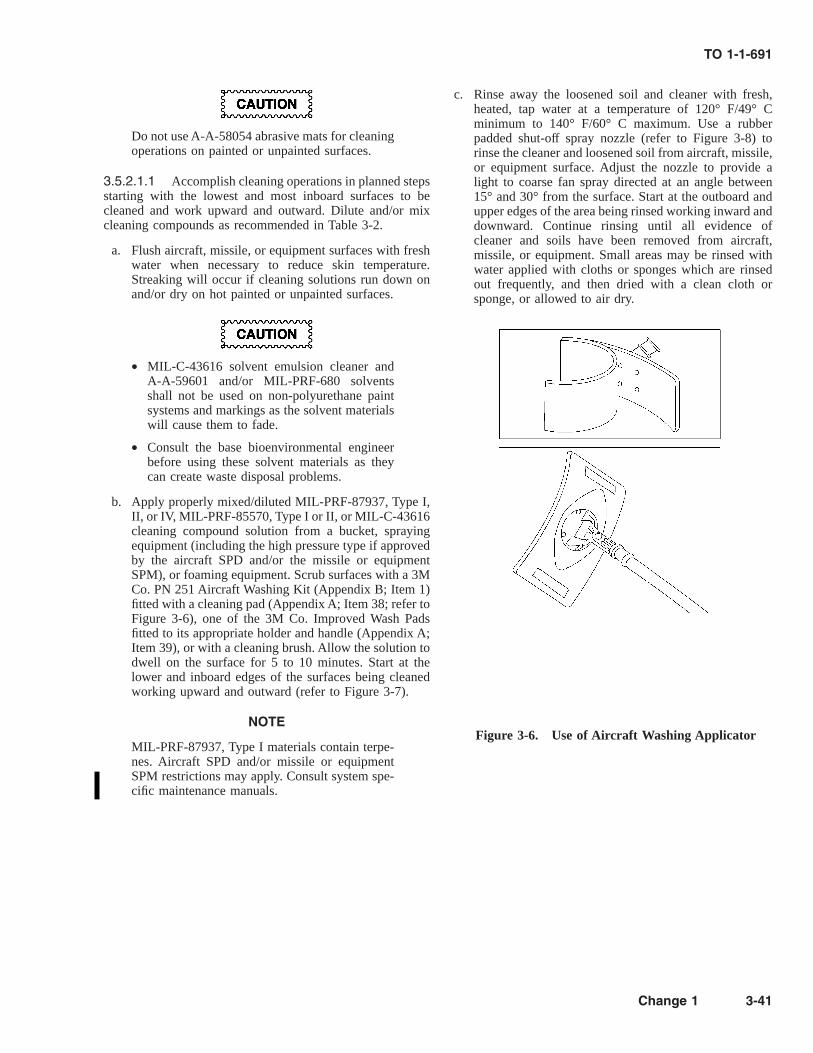
Do not use A-A-58054 abrasive mats for cleaningoperations on painted or unpainted surfaces.
3.5.2.1.1 Accomplish cleaning operations in planned stepsstarting with the lowest and most inboard surfaces to becleaned and work upward and outward. Dilute and/or mixcleaning compounds as recommended in Table 3-2.
a. Flush aircraft, missile, or equipment surfaces with freshwater when necessary to reduce skin temperature.Streaking will occur if cleaning solutions run down onand/or dry on hot painted or unpainted surfaces.
• MIL-C-43616 solvent emulsion cleaner andA-A-59601 and/or MIL-PRF-680 solventsshall not be used on non-polyurethane paintsystems and markings as the solvent materialswill cause them to fade.
• Consult the base bioenvironmental engineerbefore using these solvent materials as theycan create waste disposal problems.
b. Apply properly mixed/diluted MIL-PRF-87937, Type I,II, or IV, MIL-PRF-85570, Type I or II, or MIL-C-43616cleaning compound solution from a bucket, sprayingequipment (including the high pressure type if approvedby the aircraft SPD and/or the missile or equipmentSPM), or foaming equipment. Scrub surfaces with a 3MCo. PN 251 Aircraft Washing Kit (Appendix B; Item 1)fitted with a cleaning pad (Appendix A; Item 38; refer toFigure 3-6), one of the 3M Co. Improved Wash Padsfitted to its appropriate holder and handle (Appendix A;Item 39), or with a cleaning brush. Allow the solution todwell on the surface for 5 to 10 minutes. Start at thelower and inboard edges of the surfaces being cleanedworking upward and outward (refer to Figure 3-7).
NOTE
MIL-PRF-87937, Type I materials contain terpe-nes. Aircraft SPD and/or missile or equipmentSPM restrictions may apply. Consult system spe-cific maintenance manuals.
c. Rinse away the loosened soil and cleaner with fresh,heated, tap water at a temperature of 120° F/49° Cminimum to 140° F/60° C maximum. Use a rubberpadded shut-off spray nozzle (refer to Figure 3-8) torinse the cleaner and loosened soil from aircraft, missile,or equipment surface. Adjust the nozzle to provide alight to coarse fan spray directed at an angle between15° and 30° from the surface. Start at the outboard andupper edges of the area being rinsed working inward anddownward. Continue rinsing until all evidence ofcleaner and soils have been removed from aircraft,missile, or equipment. Small areas may be rinsed withwater applied with cloths or sponges which are rinsedout frequently, and then dried with a clean cloth orsponge, or allowed to air dry.
Figure 3-6. Use of Aircraft Washing Applicator
TO 1-1-691
Change 1 3-41

Figure 3-7. Aircraft Cleaning Procedure
TO 1-1-691
3-42

NOTE
If hot water is unavailable, regular tap water maybe used for rinsing; but it takes a great deallonger, requires much more water, and is not asefficient in removal of residue from the surface.Hot water rinsing is known to reduce man-hoursrequired for rinsing by approximately 20 percent.
d. For aircraft, or equipment painted with a low gloss/flatand/or camouflage paint scheme, ground-in soils (bootmarks, smudges, etc.) can be cleaned with MIL-PRF-85570, Type IV spot cleaner. Apply with a cleaning pador sponge; and after several minutes dwell time, scrubthese areas with the pad or sponge, and rinse thoroughly.When the rubber particles in this cleaner are rubbed withthe pad, removable soils are erased from the low areas ordepressions in the surface of the paint
e. Clean wheel, flap, aileron, elevator, rudder wells andother heavily soiled areas which can tolerate waterrinsing with MIL-PRF-87937, Type III, or MIL-PRF-85570, Type V gel cleaner. These cleaning compoundsmay be sprayed on using a hand operated pump spray.Allow to dwell for 5 to 15 minutes, and then rinsethoroughly with a rubber padded shut-off fan spraynozzle adjusted to provide a light to coarse fan spray(refer to Figure 3-8).
f. Clean painted and unpainted surfaces on aircraft, mis-siles, and/or equipment that are protected/treated withCPC’s with MIL-C-43616, Class 2 (aerosol type) sol-vent emulsion cleaner applied by spray or A-A-59601,Type II or III, or MIL-PRF-680, Type II or III degreas-ing solvents applied with a brush, cloth, sponge, ornon-atomizing spray. Rinse the area thoroughly withfresh tap water (preferably hot water), and then wash byalkaline detergent cleaning per steps b and c above.
NOTE
MIL-PRF-87937, Type III or MIL-PRF-85570,Type V gel cleaning compounds may be used asalternates to clean CPC coated areas per proce-dure in step e above.
g. If surfaces are not clean at this point, repeat the cleaningprocess.
3.5.2.2 Waterless Wipe Down. Waterless wipe downprocedures for spot cleaning will be used only when water isnot available for rinsing, or when cold weather prevents theuse of water. The waterless wipe down method for removal ofsoils and corrosive salt residues is as follows:
a. Using a plastic spray bottle, apply MIL-PRF-87937,Type I or IV, or MIL-PRF-85570, Type I or II, (mixedone part cleaner to nine parts water) to the exteriorsurfaces of the aircraft (several square feet at a time).
NOTE
MIL-PRF-87937, Type I materials contain terpe-nes. Aircraft SPD and/or missile or equipmentSPM restrictions may apply. Consult system spe-cific maintenance manuals.
b. After 30 seconds, scrub, then wipe cleaner and soil fromthe surface with the clean CCC-C-46, Type I, Class 7 orAMS 3819, Class 1, Grade B cloth.
c. Rinse the cleaned surface with fresh water when itbecomes available and/or weather permits.
3.5.2.3 Alkaline Detergent Cleaning with Only Lim-ited Fresh Water Available. Use the following procedure,only when sufficient rinse water is not available:
a. Mix either of the following in a bucket depending on thetype of soil to be removed:
(1) One part MIL-PRF-87937, Type I, II, or IV, orMIL-PRF-85570, Type I or II cleaning compoundand 16 parts water for removal of light to moderatesoils; or
(2) One part MIL-PRF-87937, Type I, II, or IV, orMIL-PRF-85570, Type I or II cleaning compoundand 4 parts water for removal of heavy soils.
NOTE
MIL-PRF-87937, Type I materials contain terpe-nes. Aircraft SPD and/or missile or equipmentSPM restrictions may apply. Consult system spe-cific maintenance manuals.
b. Apply the cleaner with a cleaning pad, sponge, cloth, orcleaning brush one small area at a time (10 to 20 SQFT).
c. Scrub the area with the applicator from step b, and thenwipe clean with a CCC-C-46, Type I, Class 7, or AMS3819, Class 1, Grade B cloth.
d. For very stubborn soils, clean with A-A-59601, Type Ior II, or MIL-PRF-680, Type I or II degreasing solvent,and then scrub with one of the above solutions (1).
3.5.2.4 Solvent Cleaning. The use of MIL-PRF-87937,Type III, or MIL-PRF-85570, Type V cleaning compoundsfor cleaning very stubborn or exceptionally oily areas onexhaust tracks, landing gears, wheel wells, control surfacewells, and engine nacelles will normally be sufficient. Whenthese materials do not completely clean these areas, A-A-59601, Type II or III, or MIL-PRF-680, Type II or III can beused in small quantities. The quantity used shall be limited tothe minimum necessary to accomplish the required cleaning.Remember that solvents will burn intensely once ignited, solimit the amount of solvent available at the aircraft, missile,or piece of equipment to a maximum of three gallons underthe use and/or control of each authorized person involved in
TO 1-1-691
Change 1 3-43

the solvent cleaning operation. Each authorized person shallbe thoroughly familiar with applicable safety precautions anddisposal requirements/information. The solvent dwell time onpainted surfaces shall be held to a minimum of 10 to amaximum of 15 minutes to prevent softening of the paint.Any dirty solvent draining off the surface during the cleaningoperation shall be controlled to prevent unauthorized entryinto the sewer. All solvent spillage shall be cleaned up perlocal regulations/directions. In no instance shall solvents beallowed to drain into or enter a public sewer or otherwise beallowed to contaminate streams or lakes. These guidelinesshall be followed when using A-A-59601, Type II or III, orMIL-PRF-680, Type II or III solvents:
a. Use only in areas approved by the local safety office.
b. Ensure that the area within 50 feet of the solventcleaning operation is clean and remains clear of allpotential ignition sources.
c. Use only explosion-proof electrical devices and powerequipment. Power units used in servicing shall be placedupwind and beyond the 50 feet clearance. Ensure thatthe aircraft, missile, or equipment is properly grounded.
d. No smoking shall be allowed in the solvent cleaningarea.
e. Mixing of solvents with other chemicals, cleaningcompounds, water, etc., is strictly prohibited except asspecified by this manual.
f. Suitable fire extinguishing equipment shall be availableto the solvent cleaning area.
g. Wear ANSI Z87.1, Type II goggles, protective wetweather clothing, solvent resistant gloves, boots, andhead covering. Use a respirator fitted with organic vaporcartridges when working in an enclosed area. Ensurethat good ventilation is maintained. Consult the localsafety office and bio-environmental engineer for PPErequirements.
h. Apply A-A-59601, Type II or III, or MIL-PRF-680,Type II or III solvents using a pad, cloth, or brush. Cleanup solvent spills as they occur.
i. Ensure that no solvent is trapped or has entered theequipment interior. Remove by wiping with clean cottonwiping cloths or by blowing dry, using clean, lowpressure air (10-15 PSI).
j. Collect waste solvents and solvent wetted wiping ragsand dispose of them per local regulations/directions.
k. After cleaning with A-A-59601 or MIL-PRF-680 sol-vents, re-clean the area using procedures in Paragraph3.5.2.1 to remove residue left by the solvents.
3.5.2.5 Interior Cleaning (Vacuum). Remove dirt,dust, small loose objects, paper, etc., from an area with anindustrial or domestic type vacuum cleaner. A soft bristlebrush on the end of the inlet tube/hose of the vacuum cleanerwill aid in removal of soils.
a. Inspect aircraft floor boards and bilge area underneaththe floor boards during depot level maintenance and asmay otherwise be required during field level mainte-nance for conditions that would necessitate cleaning orcorrosion removal and treatment. Particular attentionshall be given to urinal and latrine areas.
Accidental spills shall be investigated immedi-ately after occurrence to determine if the spilledmaterials are corrosive. Spills determined to becorrosive shall be neutralized as soon as possibleper directions in AFM 71-4 followed by cleaningper procedures in Table 3-2. Failure to complycan result in extensive corrosion damage andpossible unsafe conditions for operation of theaircraft, missile, or equipment.
b. When it is determined that harmful contamination, (i.e.,dirt spillage, foreign material, etc.) is present in anaircraft bilge area, remove the floor boards as necessaryto allow proper cleaning of the bilge area.
c. Clean the aircraft bilge area by vacuuming up all looseforeign material, dirt, etc., The vacuum removal of dirtor soil may be aided by agitating with the brush. Becareful not to sweep or wipe the dirt, etc., into oily orwet areas.
TO 1-1-691
3-44

Ensure there is adequate ventilation when usingA-A-59601, Type II or III, or MIL-PRF-680,Type II or III solvents and be sure the bilge and/orother areas are properly ventilated (blown out)before floor boards are reinstalled or closed.Warning signs shall be conspicuously placed atall aircraft entrances to indicate that combustiblematerials are being used. The guidelines cited inParagraph 3.5.2.4 for solvent cleaning proceduresapply.
d. Clean oily areas and/or spots by wiping them with aclean cloth dampened with A-A-59601, Type II or III, orMIL-PRF-680, Type II or III solvent followed immedi-ately by drying with a clean dry cloth. Do not over-saturate the cloth used for applying the solvent becausethis may result in the solvent puddling or enteringrecessed areas and creating a fire hazard. Precautionsshall be taken when using these solvents around electri-cal equipment to prevent entry.
Figure 3-8. Automatic Water Spray Nozzle
TO 1-1-691
3-45

Before starting the following cleaning operation,be sure that the spray or other method of appli-cation will not result in moisture damaging anycomponents, especially electrical components.Before using a spray method, ensure all drainholes are open, that the fluid materials will drain,and that the cleaning solution will not be forcedinto inaccessible areas. Do not apply the solutionto any moisture absorbing material such as insu-lation, sponge rubber (open cell), felt, etc.
e. If further cleaning is required, use a solution of 1 partMIL-PRF-87937, Type II or IV, or MIL-PRF-85570,Type II mixed with 9 parts fresh water applied by spray,mop, sponge, or brush. Use this solution only if it can beadequately rinsed and/or removed from the surface.
f. After applying the cleaning solution, allow dwell timeof approximately 10 minutes, agitate the solution on thesurface with a non-metallic bristle brush, and flush orrinse with clean water. Check drain holes to ensure thatthey are open and that the cleaning solution and waterare draining properly. Remove any remaining waterusing clean cloths. The surface shall then be thoroughlydried by blowing warm air over the surface or wipingwith clean, dry cloths.
g. In those areas where the above procedures cannot beused due to lack of drainage, possible damage tocomponents, etc., hand cleaning procedures will have tobe used. Apply a solution of 1 part MIL-PRF-87937,Type II or IV, or MIL-PRF-85570, Type II mixed with 9parts water to the surface with a rag or sponge wettedwith the solution and then agitate it with the applicator.Immediately following agitation of the solution, rinsethe area by wiping it with a rag wetted with clean waterand then wipe it dry with a clean, dry rag. Thisprocedure may have to be repeated several times onextremely soiled areas.
h. If corrosion is encountered and/or paint is removed, treatthe corrosion per this manual and the applicable systemspecific maintenance manual, and touch-up the paintsystem per TO1-1-8 and the applicable system specificmaintenance manual before the floor boards are replacedor area is closed.
3.5.2.6 Low Temperature Cleaning. Do not performroutine scheduled cleaning when the ambient temperature is40° F (4° C) and below. Instead, aircraft, missiles, orequipment shall be cleaned in an indoor, heated wash rack.However, if the ambient temperature is between 40° F (4° C)and 32° F (0° C) and such a facility is not available, exteriorareas/surfaces on aircraft, missiles, or equipment contami-nated with corrosive materials, such as runway deicing agentsand salt water shall have these areas/surfaces cleaned out-
doors using the waterless wipe down method in Paragraph3.5.2.2. Normal cleaning solutions cannot be used in freezingweather of 32° F (0° C) and below; so under these conditions,the following procedures shall be used for cleaning:
Table 3-3. Recommended Dilution of Low Tempera-ture Cleaner
AMBIENT TEMPERA-TURE
DILUTION RATIO (Partsmixture: parts water)
+30° F and above 1:4+10° F to +30° F 1:2+10° F and below 1:1
SAE AMS 1424, Type I aircraft deicing/anti-icing fluid is mildly toxic. Contact with skin andeyes shall be avoided. Do not inhale deicing fluidmist. Spray equipment operators and personnelusing brush applicators should stay on the wind-ward side of the aircraft and/or equipment to becleaned during cleaning solution application.Chemical, splash-proof goggles and wet weathergear, including boots and gloves, shall be wornby all maintenance personnel involved in lowtemperature cleaning operations.
TT-I-735 isopropyl alcohol or any other alcoholshall not be used for deicing acrylic plasticcanopies. Use Type AMS 1424, SAE Type Iaircraft deicing/anti-icing fluid for theseapplications.
a. If necessary, deice the aircraft, missile, or equipment perprocedures in TO 42C-1-2 and/or the applicable systemspecific maintenance manual.
b. Solvent clean heavily soiled areas of aircraft by wipingor brushing with A-A-59601, Type II or III, or MIL-PRF-680, Type II or III degreasing solvent using proce-dures in Paragraph 3.5.2.2.
c. To make a low temperature cleaner, mix ½ pint ofconcentrated/undiluted MIL-PRF-87937, Type IV orMIL-PRF-85570, Type II cleaning compound into onegallon of the ready-to-use (RTU) SAE AMS 1424, TypeI Aircraft Deicing/Anti-Icing Fluid or into one gallon ofa solution of the concentrated form of the SAE AMS1424, Type I Aircraft Deicing/Anti-Icing Fluid diluted 1
TO 1-1-691
3-46 Change 1

to 1 with water. If necessary, warm either of thesecleaning compound materials until they can be easilypoured into the deicing/anti-icing fluid. Mix thoroughly.
d. Dilute this mixture as required by the ambient tempera-ture involved per Table 3-3 and mix thoroughly.
e. Scrub the aircraft, missile, or equipment using a brush,cloth, or aircraft washing kit.
f. Rinse by deicing as in step a. Heated deicing/anti-icingfluid mixtures will speed up the rinsing process.
3.5.3 Clear Water Rinsing of Aircraft.
• Do not rinse aircraft with a solid stream ofwater. Use a soft, spray pattern to avoiddamaging fragile sections or causing waterintrusion. Water must not be directed at pitottubes, static ports, vents, etc. Critical areasshall be adequately protected with groundplugs, covers, etc.
• Application of water in wheel wells, flapwells, flight control wells, etc., may necessi-tate the relubrication of some components/areas. Ensure that these areas are adequatelydrained and check the system specific aircraftmaintenance manuals to determine lubricationrequirements.
NOTE
• Clear water rinsing does not satisfy aircraftwashing requirements.
• Only water meeting the requirements in Para-graph 3.1.1, steps f (1) through (9) shall beused for clear water rinse operations.
3.5.3.1 Requirements. As directed by the requirementsin Paragraph 3.2.3, aircraft shall be clear water rinsed toremove salt contamination from aircraft surfaces caused byoperations near salt water. Most salt deposits are readilydissolved and/or dislodged and flushed away by rinsing.Rinsing can be done in a taxi-through facility or by directmanual spraying.
3.5.3.2 Taxi-Through Rinsing. Deluge rinse facilities(bird baths) are automatic installations located in a taxiwayarea for use by aircraft after flight through salt air. Theseinstallations provide multiple jet sprays of fresh water tocover the entire aircraft exterior surface to rinse off salt andwater soluble contaminants. Such facilities should be used asfrequently as possible per the requirements in Paragraph3.2.3.
3.5.3.3 Manual Application. Fresh water can be appliedfrom a hand held hose or piece of spraying equipment. Theforce or pressure used to apply the water is not as critical asthe amount of water. Satisfactory results are achieved with anamount of water that will create a full flowing action over thesurface. This requires a minimum of eight gallons per minute(GPM) of water at a nozzle pressure of 25 PSI minimum to175 PSI maximum.
3.5.3.4 Rinsing Procedures. Clear water rinsing shallbe accomplished as follows:
a. Direct water at an angle of 15° to 30° from the surface.Ensure that sufficient water flow is achieved on allsurfaces.
b. Begin rinsing on lower surfaces and work upwardstarting with the lower wing surfaces, then the lowerfuselage, and the lower horizontal stabilizer surfaces.Then rinse from the top down, starting with the upperand lower surfaces of the horizontal stabilizer on T-tailaircraft, the vertical stabilizer surfaces, then the upperfuselage, upper wing surfaces, and upper horizontalstabilizer surfaces. (Refer to Figure 3-7).
3.5.4 Post Cleaning Procedures.
Do not use synthetic wiping cloths with flam-mable solvents as these solvents can dissolvethem.
3.5.4.1 Post Cleaning Task Sequence. Strict compli-ance with the following post cleaning procedures is essential,and they shall be done in the following order:
a. Remove covers and masking from all static vents, pitotstatic tubes, air ducts, heater ducts, etc.
b. Remove tape from all other openings sealed withmasking tape.
c. Remove all tape adhesive residues with TT-N-95 ali-phatic naphtha or TT-I-735 isopropyl alcohol.
d. Ensure all drain holes are open by inserting a probe,such as a pipe cleaner.
e. Ensure that all areas that accumulate water have beendrained and/or otherwise dried. Whenever this is arecurring problem, specialized procedures shall be de-veloped and implemented to remove entrapped waterand other fluids to prevent their accumulation.
TO 1-1-691
Change 1 3-47

An effective corrosion prevention and controlprogram requires that prescribed preservation andlubrication procedures be accomplished as soonas possible after a cleaning operation to prevent/minimize the occurrence of corrosion.
f. Upon completion of all cleaning operations, lubricate allexposed static joints and inject lubricant into all lubefittings in the areas cleaned in accordance with Para-graph 3.6 and applicable system specific maintenancemanuals to displace any entrapped water or cleaningmaterials that could cause corrosion and failure oflubricated parts if they remained.
g. Apply preservatives/corrosion preventive compounds(CPC’s) to components in the area cleaned in accor-dance with Paragraph 3.7 and applicable system specificmaintenance manuals as necessary. Cleaning com-pounds tend to remove preservatives, making previouslyprotected surfaces vulnerable to corrosion.
3.5.5 Treatment and Disposal of Wash RackWaste.
NOTE
Cleaning solutions which remove greases, oils,and surface contamination from aircraft, missiles,equipment, and components may exceed dis-charge concentration limits for oil and grease(especially where oil/water separators are notinstalled or not operating properly), naphthalene(from cleaners containing aromatic hydrocar-bons), chromium, cadmium, nickel, or otherheavy metals (from cleaning operations involvingengines or plated parts). If your wash rack is asource of hazardous waste, consult the basesafety office and/or bioenvironmental engineer todetermine corrective action. Take precautionarymeasures to prevent wash rack waste from con-taminating lakes, streams, or other natural envi-ronments. Some chemicals used for cleaningrequire treatment or other special controls prior todisposal.
3.5.5.1 The disposal of materials shall be accomplished inaccordance with applicable directives and in a manner thatwill not result in the violation of local, state, or federalpollution directives.
3.5.5.2 To reduce the problems associated with disposaland the actual cleaning process, all work shall be accom-plished on an approved wash rack. The only exception to this
requirement shall be for those facilities which are temporarilyestablished to support combat operations or special missions.
3.5.5.3 Aircraft wash rack cleaning waste shall receive theequivalent of secondary sewage treatment. When MIL-PRF-85704, Type I or MIL-C-43616, Class 1 solvent emulsioncleaning solutions are used, waste shall be released so that thetotal effluent entering the waste treatment plant does notcontain more than the amount limited by local environmentalregulations or 100 parts per million (ppm) of cleaningcompound.
3.5.6 Fungus Growth Removal.
A 50-50 by volume mixture of isopropyl alcoholand water is flammable with a flash point of 60°F. Use only with adequate ventilation, and com-ply with guidelines for solvent cleaning in thischapter.
Do not use isopropyl alcohol on transparentacrylic or polycarbonate plastics used for aircraftcanopies and windows or meththacrylate plastic(plexiglas) components as it can cause them tocraze.
Fungus growth (mildew and mold) occurs on the surface oforganic materials (plastics, paper, organic coatings/paints,etc.) and inorganic materials (metals, concrete, etc.) particu-larly in warm, damp/humid climates. Fungus growths must beremoved to prevent corrosion of metals and deterioration ofother materials caused by the fungus by-products.
3.5.6.1 Fungus Removal from Plastics. Since theterm plastics includes a wide variety of different chemicalcompounds with a wide variety of chemical and physicalproperties, one type can be cleaned by a method which candeteriorate another type. In general, organic solvents, mineralspirits, and paint thinners should not be used to clean plasticsor be allowed to come in contact with them. Except as notedabove, remove fungus from plastics by scrubbing the con-taminated area with a lint-free cloth or a sponge wet with a50-50 by volume solution of TT-I-735, Grade A or B, andfresh tap water with two (2) fluid ounces of P-D-410, Type IIdetergent per gallon of solution mixed in. Wipe off the residuewith a lint-free cloth wet with fresh tap water and wipe drywith a clean dry cloth. Clean fungus from transparent plasticsand plastic electrical insulation as follows:
TO 1-1-691
3-48 Change 1
TT-N-95 aliphatic naphtha is flammable and toxicto the skin, eyes, and respira-tory tract. Keepaway from all sources of ignition. Avoid skin andeye contact. Good general ventilation is adequate.
TT-N-97 aromatic naphtha shall not be used toclean transparent plastics as it can attack anddamage them.
a. Remove fungus from acrylic, polycarbonate, and meth-acrylate (plexiglas) transparent plastic com-ponentswith a lint-free cloth or sponge wet with TT-N-95aliphatic naphtha, and then wipe dry with a clean, drycloth. If polishing is required, rub the area with SS-P-821, Grade F or finer pumice ground abrasive. ConsultTO 1-1A-12 for details on polishing transparent plastics.
b. Remove fungus from plastic electrical insulation bywiping with a lint-free cloth or sponge wet with a 50-50by volume solution of TT-I-735, Grade A or B isopropylalcohol and fresh tap water, and then wipe dry with aclean, dry cloth. Consult TO 1-1-689 for additionalinformation on cleaning electrical insulation.
3.5.6.2 Fungus Removal from Metal Surfaces. Re-move fungus from all metal surfaces other than electricalconnectors by first wiping the contaminated area with alint-free cloth or sponge wet with TT-I-735, Grade A or Bisopropyl alcohol followed by cleaning per the standardmethods in Table 3-2 for the type of area involved. Removefungus from electrical connectors as follows:
a. Remove fungus from exterior surfaces of electricalconnectors by wiping with a lint-free cloth or brushingwith a non-metallic bristle brush (tooth brush) wet withTT-I 735, Grade A or B isopropyl alcohol followed byrinsing with a stream of the alcohol from a plastic washbottle and then drying with clean, dry, oil free com-pressed air (15 PSI max).
b. Remove fungus from male pins/contacts using the samemethods as for the exterior surfaces of the electricalconnector.
NOTE
Consult TO 1-1-689 for additional information oncleaning of electrical connectors.
c. Remove fungus from female pins/contacts by scrubbingwith a pipe cleaner or a toothpick saturated withTT-I-735, Grade A or B isopropyl alcohol followed byrinsing with a stream of the alcohol from a plastic washbottle and drying with clean, dry, oil free compressed air(15 PSI max).
3.5.7 Soil Barriers.
Do not apply soil barrier materials to any areaother than engine exhaust and gun gas residueareas on aircraft having a camouflage or a flatpaint scheme. These materials increase the specu-lar gloss and IR reflectance of paint systemsthereby compromising the effectiveness of thecamouflage and flat paint schemes.
Soil barriers are transparent materials that are very effectivein preventing damage to both painted and unpainted engineexhaust track areas and areas exposed to gun gas residue onaircraft and/or other equipment. Soil barrier materials shall beapplied to these areas on aircraft immediately after curing ofa new or overcoat paint system prior to engine run andexisting paint systems after each aircraft wash as a part of theaircraft wash. Soil, soot, and/or gun gas residue graduallyaccumulate on or in the soil barrier film instead of the paintsystem protected by the film. when the protected area doesn’tmeet acceptable aircraft or equipment appearance standards,or an aircraft undergoes a routine wash, remove the soilbarrier film per Paragraph 3.5.7.3 and reapply per Paragraph3.5.7.2 using materials specified in Paragraph 3.5.7.1.
3.5.7.1 Materials. McGean-Rocho, Inc. PN Cee-BeeA-6 and Eldorado Chemical Co., Inc. PN PC-1020 are thesoil barrier materials approved for use on Air Force aircraftand equipment.
NOTE
• Rain or water do not deteriorate soil barriermaterials; but solvents, alkaline cleaners, andsolvent emulsion cleaners tend to degradeand/or remove them.
• If the temperature of the surfaces to be treatedwith soil barriers reaches or exceeds 100° F(38° C), cool the surfaces with a light spray offresh water before applying soil barrier mate-rials.
• No prior cleaning and/or rinsing of an area isrequired if soil barriers are being applied on anew or overcoat paint system.
3.5.7.2 Application. If an old soil barrier film is presenton the surface, remove it per Paragraph 3.5.7.3.
a. Thoroughly clean surface with MIL-PRF-87937, Type IIor MIL-PRF-85570, Type II cleaning compound perTable 3-2 and Paragraph 3.5.2.1.
b. Rinse surface thoroughly with fresh water to remove allgrease, oil, dirt, and cleaning compound residue andallow the water to drain off.
TO 1-1-691
3-49

c. When most of the rinse water has drained off, apply auniform film of either soil barrier material listed inParagraph 3.5.7.1 with a non-atomizing type sprayer(garden sprayer), brush, or roller, and allow the film todry for one hour before releasing the aircraft or equip-ment.
d. Flush the sprayer and/or rinse the brush or roller withfresh water immediately after completing the applica-tion operation. If soil barrier materials dry on/in appli-cation equipment, remove it with A-A-59601, Type II orIII, or MIL-PRF-680, Type II or III degreasing solventor soak the equipment in a solution of one part MIL-PRF-87937, Type II or MIL-PRF-85570, Type II clean-ing compound and four parts water for a minimum offour hours.
3.5.7.3 Removal.
a. Apply McGean-Roncho, Inc. PN Cee-Bee A-276 orEldorado Chemical Co., Inc. PN Astromat A soil barrierremover or A-A-59601, Type II or III, or MIL-PRF-680,Type II or III degreasing solvent to the surface from
which the soil barrier film is to be removed with anon-atomizing sprayer, mop, brush, or cloth.
NOTE
• Soil barrier removers may be used as receivedor diluted 1 to 1 with water, but undilutedworks best.
• Soil barrier removers are to be used only forremoval of soil barrier films. They shall not beused for any other type of aircraft or equip-ment cleaning
b. Allow the soil barrier remover or solvent to dwell on thesurface until it penetrates the soil barrier film (usuallyabout 20 to 60 minutes).
c. Scrub the area thoroughly with a brush or 3M Co. PN251 aircraft washing kit fitted with a non-abrasivecleaning pad or sponge, and then flush the area withfresh water.
d. Reapply soil barrier material per Paragraph 3.5.7.2.
SECTION III LUBRICATION
3.6 INTRODUCTION.
Lubrication performs a dual purpose: to prevent wear be-tween moving parts; and also to fill air spaces, displace water,and provide a barrier against corrosive elements. The lubri-cation requirements contained in system specific maintenancemanuals and/or cards are usually adequate to prevent corro-sion of most lubricated surfaces under normal operatingconditions. Aircraft lubrication shall be accomplished only bypersonnel qualified in lubrication procedures. In the eventthat the specified lubricant is not available, request substitu-tions from the aircraft SPD and/or the missile or equipmentSPM.
NOTE
Comply with relubrication time frame require-ments outlined in the system specific mainte-nance manual.
3.6.1 Conventional Lubricants. Table 3-4 contains thetitle, specification, intended use, and temperature range of themost frequently used conventional lubricating materials.
3.6.2 Solid Film Lubricants.
• Not all lubricating materials are compatiblewith each other and/or metals used in AirForce aircraft, missiles, or equipment. Someare known to promote galvanic corrosion orcause paint or acrylic plastics to deteriorate.Using the correct lubricating material is criti-cal. Do not use greases or oils with solid filmlubricants. Use only lubricants specified byappropriate system specific manuals and/orcards.
• Do not lubricate Teflon bearings or bushings.Clean Teflon bearings and bushings with A-A-59601, Type II or III, or MIL-PRF-680, TypeII or III degreasing solvent.
• Lubricants containing graphite, either alone orin mixture with any other lubricants, shall notbe used since graphite is cathodic to mostmetals and will cause galvanic corrosion in thepresence of electrolytes.
TO 1-1-691
3-50 Change 1

Solid film lubricants are used where conventional lubricantsare difficult to apply or retain, or where other lubricants maybe contaminated with dust, wear products, or moisture and toreduce fretting corrosion on close tolerance fittings that seeprimarily static loads with only very small relative movementcaused by vibration. Typical applications of solid film lubri-cants are sliding motion components such as flap tracks,hinges, turnbuckles and cargo latches.
• Do not use solid film lubricants in areassubject to rotational speeds above 100 RPMunder heavy loads or on roller bearing ele-ments because they will not provide adequatelubrication in these situations.
• Do not use solid film lubricants in conjunctionwith oils or greases as they are not compatible.
3.6.2.1 As with paints, surface preparation prior to appli-cation is extremely important to the service wear life of solidfilm lubricants. In reality, solid film lubricants are nothingmore than paints with solid (powder) type lubricants used asthe pigment. They are usually applied over surfaces pre-coated with other films, such as anodize (aluminum andmagnesium base material), phosphate (steel base material),and sometimes over organic coatings such as epoxy primers.
3.6.2.2 SAE AS5272 (MIL-PRF-46010), Lubricant, SolidFilm, Heat Cured, Corrosion Inhibiting is a heat cured,corrosion-inhibiting, solid film lubricant that provides ex-tended wear life. It can be used on aluminum, copper, steel,stainless steel, and titanium in areas of infrequent operationand in areas requiring long term protection under staticconditions to prevent galling, corrosion, and metal seizure.Because SAE AS5272 (MIL-PRF-46010), Type I must becured at 400° F (205° C) for one hour and Type II must becured at 300° F (149° C) for two hours, they are not suitablefor all applications as metallurgical damage may occur atthese temperatures.
3.6.2.3 MIL-PRF-46147 and/or MIL-L-23398, Lubricant,Solid Film, Air Cured, Corrosion Inhibiting are air-cured,corrosion-inhibiting, solid film lubricants that can be used onaluminum, steel and titanium in areas of infrequent operationand areas requiring long term protection under static condi-tions to prevent galling, corrosion, and metal seizure. Theyprovide moderate wear life and corrosion protection in theseareas when it is not feasible to use a solid film lubricant thatrequires curing at elevated temperatures, and can be used torepair damaged SAE AS5272 (MIL-PRF-46010) heat-cured,solid film lubricants. MIL-L-23398, Type I (bulk) and Type II
(aerosol) both require a 6 hour cure at a temperature of 77°±3° F(25° ±2° C). MIL-PRF-46147, Form 1 (bulk) and Form2 (aerosol); Type I (standard solvents) require a 18 hour cureand Type II (low VOC content), both forms, require a 24 hourcure at these same temperatures. Curing of both MIL-L-23398 and MIL-PRF-46147 solid film lubricants may beaccelerated by allowing air drying at room temperature for 30minutes to flash off solvents and then heating to 125° ±5° F(52° ±3° C) for 1 to 1½ hours.
3.6.3 Application of Conventional Lubricants.
When lubricating hinges and pinned joints, applya generous quantity of either MIL-PRF-63460(preferably); MIL-PRF-81309, Type II; or MIL-PRF-32033 water displacing, Corrosion Preven-tive Compound (CPC) before applying the speci-fied lubricant. Actuate hinges several times tomake sure that the CPC’s and lubricants penetrateall crevices thoroughly, and then wipe off excessfrom exterior surfaces.
3.6.3.1 Apply lubricants as sparingly as possible toprevent accumulation of dust, dirt, and other foreign matter,but always apply enough to provide adequate lubrication.Wipe away any excess lubricant. Using the proper method ofapplication as specified in the appropriate system specificmaintenance manual is important. Apply lubricants by one ofthe following methods:
• Grease guns: lever or pressure type
• Oil, squirt, and aerosol spray cans
• Hand or brush
3.6.3.2 Grease Gun Application. When applyinggrease type lubricants in pressure type grease fittings (Zerkfittings) with a grease gun, clean grease fitting with A-A-59601, Type II or III, or MIL-PRF-680, Type II or IIIdegreasing solvent and clean cloth before applying lubricant.Make sure the lubricant has emerged around the bushing. Ifno grease appears, check the fitting and grease gun for properoperation. Be certain the grease gun is properly attached tothe fitting prior to applying pressure. When applying grease toa flush type (high pressure) fitting, make sure that the greasegun is fitted with a flush type adapter and held perpendicularto the surface of the fitting before applying pressure. If thefitting does not accept lubrication, replace the fitting andlubricate. Wipe excess grease from the fitting and the sur-rounding surfaces with a clean, dry cloth.
TO 1-1-691
Change 1 3-51

Table 3-4. Common Military Greases the Their Uses
Specification and Nomencla-ture
Intended Use Recommend Temperature Range
AMS-G-4343 Grease, Pneu-matic System (NATO CodeG-392)
Lubrication between rubber and metal partsof pneumatic systems; pressurized cabinbulkhead grommets and other mechanismsrequiring rubber to metal lubrication.
-65° to 200° F (-54° to 93° C)
AMS-G-6032 Grease, Plug,Valve, Gasoline and Oil Re-sistant (NATO Code G-363)
Tapered plug valves; gasket lubricant or seal;general plug valve and fitting use wheregasoline, oil, alcohol, or water resistance isrequired.
-32° to 200° F (0° to 93° C)
MIL-G-21164 Grease, Molyb-denum Disulfide, for Lowand High Temperatures(NATO Code G-353)
Heavily loaded steel sliding surfaces, acces-sory splines, or anti-friction bearings car-rying high loads and operating throughwide temperature ranges where molybde-num disulfide will prevent or delay seizurein the event of inadequate lubrication. Thisgrease is not intended for use in wheelbearings.
-100° to 250° F (-73° to 121° C)
MIL-PRF-23827 Grease, Air-craft and Instrument, Gearand Actuator Screw (NATOCode G-354)
Lubrication of ball, roller, and needle bear-ings, gears, and sliding and rolling sur-faces of equipment such as instruments,cameras, electronic gear and aircraft con-trol systems that are subject to extrememarine and low temperature conditions;rolling and sliding surfaces of equipmentwith low motivating power (low torqueequipment); general use on aircraft gears,actuator screws, and other equipment withhigh load carrying capacity. Its extremelylow volatility makes it useful on aircraftoptical equipment since it will not produceoil fogging
-100° to 250° F (-73° to 121° C)
MIL-G-25013 Grease, Aircraft,Ball and Roller Bearing(NATO Code G-372)
Lubrication of ball and roller anti-frictionbearings that operate at extreme high orlow temperatures, especially in applica-tions where soap-type petroleum or syn-thetic oil greases and oils cannot be used.Can be used on aircraft actuators, gear-boxes, and similar equipment.
-100° to 450° F (-73° to 232° C)
MIL-G-25537 Grease, Aircraft,Helicopter, Oscillating Bear-ing (NATO Code G-366)
Lubrication of aircraft bearings having oscil-lating motion of small amplitude.
-65° to 160° F (-54° to 71° C)
MIL-PRF-27617 Grease, Air-craft and Instrument, Fueland Oxidizer Resistant
Lubrication of taper plug valves, gaskets,and bearings in aircraft and ground supportequipment fuel systems; lubrication ofvalves, threads, and bearings of liquid oxy-gen (LOX) systems of aircraft, aerospacevehicles, and support equipment. Do notuse on aluminum or magnesium dynamicbearings due to possible ignition hazard.
Type I (NATO Code G-397) -65° to +300° F (-54° to +149° C)Type II (NATO Code G-398) -40° to +400° F (-40° to +204° C)
TO 1-1-691
3-52

Table 3-4. Common Military Greases the Their Uses - Continued
Specification and Nomencla-ture
Intended Use Recommend Temperature Range
Type III (NATO Code G-399) -30° to +400° F (-34° to +204° C)Type IV (NATO Code G-1350) -100° to +400° F (-73° to +204°C)Type V -100° to +450° F (-73° to +232° C)MIL- PRF-81322 Grease, Air-
craft, General Purpose, WideTemperature Range (NATOCode G-395)
NLGI Grade 1: arresting gear sheave spacersand other equipment that operates underhigh contact loads and high sliding speeds.
-65° to +350° F (-54° to +177° C)
NLGI Grade 2: aircraft wheel bearings andinternal brake wheel assemblies, anti-friction bearings, gearboxes, and plainbearings. Both will withstand high speedoperations and operations on equipmentsubject to extreme marine environments.
SECTION IV PRESERVATION
3.7 INTRODUCTION.
Corrosion preventive compounds (CPC’s), or preservatives,are used to protect metal aircraft, missile, and equipmentparts and components by preventing corrosive materials fromcontacting and corroding bare metal surfaces. Many of thesecompounds are also able to displace water, including seawater, and other contaminants from these surfaces; and someprovide lubrication, as well as corrosion protection. Gener-ally, CPC’s are mixtures of special additives in petroleumderivative bases (special oils or greases). CPC’s range inappearance and consistency from the thick, black types, suchas MIL-C-16173, Grade 1, to light oils, such as MIL-PRF-32033. The thicker CPC’s provide the best corrosion protec-tion, are longer lasting, and are more difficult to remove. Thethinner materials provide some lubrication and do not crack,chip, or peel; but they must be removed and replacedregularly to provide continuing protection.
3.7.1 Operational Preservation. The day to day appli-cation of CPC’s to prevent corrosion on operational aircraft isknown as operational preservation. Areas which are corrosionprone or where paint has been damaged should be routinelyprotected by CPC’s until more permanent treatment, such aspaint touch-up or sealant, can be applied.
3.7.2 Non-Operational Preservation. Preservation ofaircraft or components during periods of prolonged inactivity,storage, or shipment is known as non-operational preserva-tion.
3.7.3 Types of CPC’s. CPC’s can be separated into twomajor categories: water displacing and non-water displacingcompounds.
3.7.3.1 Water Displacing Compounds. Water displac-ing CPC’s can be used to remove water, in-cluding sea water,or other electrolytes from metal surfaces. MIL-PRF-81309,MIL-PRF-63460, MIL-PRF-16173, Grade 3, and MIL-PRF-32033 are water displacing CPC’s that are able to penetrateinto cracks, crevices, voids at faying surface edges, aroundfastener heads, and into hinges. They usually provide verythin coatings, one mil (0.001 inch) or less in thickness, thatare clear or translucent and remain soft and oily afterapplication, so they cannot provide long term protectionoutdoors or in areas which are frequently handled. Anothertype, MIL-DTL-85054, differs from the other water displac-ing compounds as it doesn’t penetrate into joints very well,but forms a relatively hard, dry film on exterior surfaces, andtherefore, it can be used for protection outdoors and in areasof frequent handling.
3.7.3.2 Non-Water Displacing Compounds. Non-water displacing CPC’s may be used on dried surfaces or onsurfaces which have been first treated with a water displacingCPC. MIL-PRF-16173, Grades 1, 2 and 4 are non-waterdisplacing CPC’s. They are heavier bodied, waxy typegreases which provide long term corrosion protection byforming a barrier film on metal surfaces. These CPC’sprovide thicker coatings and are light brown to very darkbrown in color, with a waxy greasy appearance. They providegood corrosion protection in areas where large amounts ofwater collect on or run off of structures.
3.7.4 Time Limitations of CPC’s. Because of theirtemporary nature, CPC’s must be regularly removed andreplaced to provide continuing corrosion protection. Table3-5 provides the recommended time intervals for indoor andoutdoor CPC use.
TO 1-1-691
Change 1 3-53

Table 3-5. Time Limitations for CPC’s
CPC Outdoor1 Indoor2 3Indoor Covered
Soft Thin FilmsMIL-PRF-81309, Type II 14 Days 30 Days 180 DaysMIL-PRF-81309, Type III 5 Days 14 Days 90 DaysMIL-L-87177, Grade B 5 Days 14 Days 90 DaysMIL-PRF-16173, Grade 3 14 Days 30 Days 180 Days
Lubrication and ProtectionMIL-PRF-32033 5 Days 30 Days 180 DaysMIL-PRF-63460 5 Days 30 Days 180 Days
Hard Thick FilmsMIL-DTL-85054 90 Days 210 Days 365 DaysMIL-PRF-16173 Grade 4 90 Days 210 Days 365 DaysMIL-PRF-16173 Grade 2 90 Days 210 Days 365 DaysMIL-PRF-16173 Grade 1 210 Days 365 Days 365 Days
1 Outdoor: Without cover; exposed to elements in a mild climate; absence of Outdoor: Without cover; exposed to elementsin a mild climate; absence of Outdoor: Without cover; exposed to elements in a mild climate; absence of rain and otherwashing forces; free from air and water borne pollutants.
2 Indoor: Hangars, shop areas, storage or parts accumulation areas, warehouses3 Indoor covered: Items are wrapped or sealed in a water-resistant material and stored indoors in a hangar, warehouse, or
shop area. Soft thin film CPCs were designed for indoor use and ease of removal.
Table 3-6. Corrosion Preventive Compounds
Specification and Nomenclature Intended Use Type of Coating
WATER-DISPLACING CPC’sMIL-PRF-32033 Lubricating Oil,
General Purpose, Preservative,(Water Displacing, Low Tempera-ture); Military Symbol PL-S;NATO Code O-190
Lubrication and corrosion protectionof hinges, other moving parts, smallarms and automatic weapons, andwherever a low temperature, waterdisplacing lubricant is required; re-quires frequent reapplications.
Soft, oily coating and lubricant
MIL-PRF-63460 Lubricant, Cleaner,and Preservative for Weapons andWeapons Systems; Military Sym-bol CLP; NATO Code S-758
Lubrication and short term preserva-tion of hinges, and small and largecaliber weapons in all climatic con-ditions within a temperature rangeof -65° to +150° F (-54° to +66° C);facilitates the effective removal offiring residues, gums, and other con-taminants from weapons componentswhile providing adequate lubricationand short term preservation. Of allwater displacing CPC’s, this mate-rial is the best lubricant. Excellentwater displacing characteristics andpenetration into tight joints.
Thin corrosion preventive lubricantfilm
TO 1-1-691
3-54 Change 1

Table 3-6. Corrosion Preventive Compounds - Continued
Specification and Nomenclature Intended Use Type of Coating
MIL-PRF-16173 Corrosion Preven-tive Compound, Solvent Cutback,Cold Application, Grade 3
Displacement of water; short term cor-rosion protection of metal surfacesduring shipment, storage, and in-service use; can be used on movingparts where minor lubrication is re-quired, such as on hinges, bombracks, and sliding parts.
Soft, oily, thin film (1.0 mil), lightamber color
MIL-PRF-81309 Corrosion Preven-tive Compounds, Water Displacing,Ultra-thin Film
Type II Displacement of water; short term cor-rosion protection of metal surfacesduring shipment, storage, and in-service use; corrosion protection ofmoving parts where very minor lu-brication is required, such as hingeareas, bomb racks, and sliding parts.Cannot be used on interior of elec-trical or electronic equipment andconnectors.
Soft, oily, very thin film (0.5 mil)translucent, light amber color
Type III Displacement of water; corrosion pro-tection of electrical, avionics, andother electronic equipment, electricalconnector plugs and contact pins.This material and MIL-L-87177,Grade B are the only CPC’s that canbe used on the interior of electricalor electronic equipment and connec-tors
Soft, oily, ultra thin film (0.2 mil),translucent, light amber color.
MIL-L-87177 Lubricants, CorrosionPreventive, Water Displacing, Syn-thetic Grade B
Displacement of water, corrosion pro-tection, and some lubrication on in-service lightly loaded moving parts.Can be used on interior of electrical,avionics and other electronics equip-ment and connectors
Soft, oily, thin film (0.5 mil), translu-cent, light amber color
MIL-DTL-85054 Corrosion Preven-tive Compound, Water Displacing,Clear (AMLGUARD)
Corrosion protection and water dis-placement for non-moving parts,such as skin seams, installed fas-tener heads where paint has cracked,access panel edges, and areas withdamaged paint. Cannot be used oninterior areas of electrical or elec-tronics equipment and connectors orin joint areas of moving parts as itdries to a hard film.
Dry, thin film (1.0 mil), transparent,colorless to slight blue tint
NON-WATER DISPLACING CPC’sMIL-PRF-16173 Corrosion Preven-
tive Compound, Solvent Cutback,Cold Application
TO 1-1-691
Change 1 3-55

Table 3-6. Corrosion Preventive Compounds - Continued
Specification and Nomenclature Intended Use Type of Coating
Grade 1 Protection of metal surfaces againstcorrosion when exposed with orwithout covering indoors or out-doors. Cannot be used if tempera-tures will fall below 0° F (-18° C)as the film will crack and can spallfrom the surface leaving it unpro-tected.
Hard, tack-free, thick film (4.0 mils),dark brown or black color
Grade 2 Protection of metal surfaces againstcorrosion during rework or storage;film remains tacky.
Soft, non-drying, thick (2.0 mils),light brown color
Grade 4 Protection of metal surfaces againstcorrosion during indoor storagewhen a transparent coating is re-quired; coating of aircraft and equip-ment interior, metal wire controlcables.
Soft, tack-free, thick (2.0 mils), lightbrown color
3.7.5 Description of CPC’s. A list of CPC’s and theirintended uses is summarized in Table 3-6.
3.7.5.1 MIL-PRF-81309, Corrosion Preventive Com-pound, Water Displacing, Ultra Thin Film and MIL-L-87177, Lubricants, Corrosion Preventive, Water Dis-placing, Synthetic.
MIL-DTL-85054, MIL-PRF-63460, and MIL-PRF-81309 have been revised to eliminateODC’s. Some reformulated products now containflammable solvents and/or propellants. Pay closeattention to all CAUTION/WARNING labels onthe product containers.
MIL-PRF-81309 and MIL-L-87177 materials are generalpurpose corrosion preventive compounds for use when a thin,water displacing CPC is needed. MIL-PRF-81309 and MIL-L-87177 are for indoor protection and short term protectionwhere surfaces can be recoated when required. These mate-rials are excellent water displacing compounds which providean ultra thin, soft film (0.5 mil or less). The MIL-PRF-81309specification covers two types of materials and the MIL-L-87177 specification covers one grade of material that areuseful for Air Force purposes to provide temporary protectionfrom corrosion while still being easily removable with a
solvent. They should not be used around LOX fittings. All ofthese CPC’s may be applied by either dipping, brushing, orspraying with a pump or aerosol sprayer.
3.7.5.1.1 MIL-PRF-81309, Type II and MIL-L-87177,Grade B. These CPC’s form a soft, thin film for generaluse on moving or sliding parts where some lubrication isneeded, such as on hinges or bomb rack components. Thesematerials can be easily washed away by rain or washprocedures, so frequent reapplication may be required. Theyare useful in the protection of areas which cannot be properlydrained or contain recesses that are particularly difficult toreach due to their excellent water displacing abilities.
3.7.5.1.2 MIL-PRF-81309, Type III and MIL-L-87177,Grade B. These CPC’s form an ultra thin, soft film thatprovides excellent water displacement and corrosion protec-tion for the interior of electrical, avionics and other electronicequipment and connectors. Although these CPC coatings arenon-conductive, they will allow electrical contact becausetheir very soft, thin film is easily moved aside by mechanicalaction or contact. These materials are the only CPC’s allowedfor interior use on electrical and electronics equipment.
3.7.5.2 MIL-DTL-85054, Corrosion Preventive Com-pound, Clear (AMLGUARD). AMLGUARD is a waterdisplacing CPC which forms a clear, hard/dry, semi-flexiblefilm. It is intended for use as a protective coating on baremetal areas where the paint system has been damaged or
TO 1-1-691
3-56 Change 1
failed until touch-up and/or repainting is practical. Because ofits paint-like characteristics, it provides no lubrication andblocks electrical conductivity.
Ensure that all areas where MIL-DTL-85054 isapplied are fully dried before sealing an area.Although MIL-DTL-85054 is a corrosion preven-tive compound, its solvent vapors may causecorrosion if not allowed to dissipate.
3.7.5.2.1 AMLGUARD can be applied by either dipping,brushing, or spraying with a paint spray gun or an aerosolcan, but it is primarily applied by spraying from aerosol cans.Invert the aerosol can after each use and spray to clear thespray tip (nozzle) of entrapped material. If an aerosol candoes not spray, invert and depress the spray tip several timesto clear the delivery tube and spray tip (nozzle). If the can stilldoes not spray, remove and clean the plastic spray tip(nozzle), and then reinstall the spray tip (nozzle), and sprayagain to clear the delivery tube. Dip application provides onlya very thin coating and therefore much less corrosion protec-tion.
3.7.5.2.2 Remove AMLGUARD if it is damaged due toabrasion, there are cracks in the coating, or if there is
evidence of corrosion under the coating. Since excessiveAMLGUARD buildup is difficult to remove, especially afterprolonged exposure to direct sunlight, remove previouslyapplied coatings before reapplication. If the solvents recom-mended in Table 3-7 do not remove old films of AML-GUARD, spraying on fresh AMLGUARD to soften the filmand wiping or rubbing while wet is often effective.
3.7.5.3 MIL-PRF-16173, Corrosion Preventive Com-pound, Solvent Cutback, Cold Application. MIL-PRF-16173 covers five different grades of CPC’s which can beapplied by brushing or dipping. Grades 1, 2, and 4 do notdisplace water and must be applied to dried surfaces or tosurfaces which have been treated with MIL-PRF-81309, TypeII or III, MIL-L-87117, Grade B, or MIL-PRF-16173, Grade3.
3.7.5.3.1 Grade 1. A thick, hard, black CPC which canbe removed with difficulty using mineral spirits or degreasingsolvents. It offers the most corrosion protection of all theCPC’s indoors and outdoors, and may be used at tempera-tures down to 0° F(-18° C). If used at temperatures below 0°F (-18° C), the CPC film can crack and spall off leaving thesurface unprotected.
Table 3-7. Preservation of Specific Areas and Components
Area or Component CPC Application Instructions Removal Instructions
NOTE
Prior to the application of preservatives (CPC’s), ensure removal of old preservative CPC coatings.
EXTERIOR SURFACESNOT REQUIRING LU-BRICATION
Unpainted areas and areaswith damaged paint whichdo not require lubrication(fastener heads; fayingsurface, access panel,door, and frame edges;attachment points; non-moving attachment hard-ware; wheel well areas;ram air ducts; and flap/slat cavities)
MIL-DTL-85054 or Wipe off dirt and excessmoisture. Apply thin coat-ing of AMLGUARD. Al-low to dry ½ hour. Applya second coat.
Use a non-synthetic wipingcloth wet with A-A-59601,Type II or III, or MIL-PRF-680, Type II or IIIdegreasing solvent. Forstubborn AMLGUARD,refer to Paragraph3.7.5.2.2.
MIL-PRF-81309, Type IIor
Wipe off dirt and excessmoisture. Apply a coatingof MIL-PRF-81309, TypeII or MIL-L-87177, GradeB followed by a coating ofMIL-PRF-16173, Grade 4.
MIL-L-87177 Grade Band
MIL-PRF-16173, Grade 4
EXTERIOR SURFACESNOT REQUIRING HIGHPERFORMANCE LU-BRICANT OR HY-DRAULIC FLUID
TO 1-1-691
Change 1 3-57

Table 3-7. Preservation of Specific Areas and Components - Continued
Area or Component CPC Application Instructions Removal Instructions
Sliding or moving parts re-quiring only minor lubri-cation (bomb rack compo-nents, hinges, door locks)
MIL-PRF-63460 or Apply a continuous wet coatof MIL-L-63460.
Use a non-synthetic wipingcloth wet with A-A-59601,Type II or III, or MIL-PRF-680, Type II or IIIdegreasing solvent.
MIL-PRF-81309, Type IIor
Apply a coating of MIL-PRF-81309, Type II orMIL-L-87177, Grade Bfollowed by a coating ofMIL-PRF-32033. Ifhandled, reapply as neces-sary.
MIL-L-87177, Grade Band MIL-PRF-32033
THREADED SURFACES MIL-PRF-63460 or Dip screws or fasteners inCPC and install. Whendisassembly is frequent,use MIL-PRF-63460, pre-ferably, or use MIL-PRF-81309, Type II or MIL-L-87177, Grade B asalternates. When disassem-bly is infrequent, use MIL-C-16173, Grade 4 for longterm protection.
Immerse screws or fastenersin A-A-59601, Type II orIII, or MIL-PRF-680, TypeII or III degreasing solventand blot or blow dry.
Screws, various fasteners MIL-PRF-81309, Type IIor
MIL-L-87177, Grade B or
MIL-C-16173, Grade 4
HYDRAULIC PISTONSURFACES
System hydraulic fluid Wipe exposed surface with acloth dampened with thehydraulic fluid used in thesystem. Always wipe awayfrom seals. Take care notto scratch surfaces.
Do not remove.
Reapply as necessary.
ELECTRICAL CONNEC-TOR SHELLS (EXTE-RIOR SURFACES)
NOTE
For additional information refer to TO 1-1-689.
Connector shells located incontrol surface wells,wheel wells, bilge areas,and other interior areas ofaircraft and missiles, andall areas of other equip-ment
MIL-DTL-85054 or Wipe off dirt and excessmoisture. Apply thin coat-ing of MIL-DTL-85054(AMLGUARD). Do notallow CPC to contact in-ternal surfaces. Allow todry ½ hour, and then ap-ply a second coat.
Use a non-synthetic wipingcloth wet with A-A-59601,Type II or III, or MIL-PRF-680, Type II or IIIdegreasing solvent.
For stubborn AMLGUARD,refer to Paragraph3.7.5.2.2.
MIL-C-8130,9 Type II orIII or
Wipe off dirt and excessmoisture. Apply coating ofMIL-PRF-81309, Type IIor III, or MIL-L-87177,Grade B followed by acoating of MIL-PRF-16173, Grade 4.
MIL-L-87177, Grade BAnd
MIL-PRF-16173, Grade 4
ELECTRICAL CONNEC-TOR SHELLS (INTE-RIOR SURFACES)
NOTE
For additional information refer to TO 1-1-689.
TO 1-1-691
3-58 Change 1

Table 3-7. Preservation of Specific Areas and Components - Continued
Area or Component CPC Application Instructions Removal Instructions
Do not use any other type of CPC than thoselisted here on the interior of electrical connectorshells as all other types will interfere with electri-cal conductivity.
Connector shells located inall the same areas notedfor exterior surfaces ofconnectors
MIL-PRF-81309, Type IIIor
Wipe off dirt and excessmoisture. Apply a thin,uniform coating of CPC.
Use a non-synthetic wipingcloth wet with TT-I-735isopropyl alcohol.
MIL-L-87177, Grade B
ELECTRICAL CONNEC-TOR PINS (ALL)
Do not use anyother type of CPCthan those listedhere on electricalconnector pins andsockets as theywill interfere withelectricalconductivity.
Connector pins and sockets MIL-PRF-81309, Type IIIor
Apply a continuous thin, wetcoat of CPC. If handled orexposed to water, reapply.
Use an acid brush with non-synthetic bristles to applyTT-I-735 isopropyl alcoholto pins and sockets.Lightly dab all pins andsockets, and then blot dry.
MIL-L-87177, Grade BELECTRICAL AND ELEC-
TRONIC EQUIPMENTRefer to TO 1-1-689.
CONTROL CABLES (ALL)(INTERIOR AND EXTE-RIOR)
MIL-PRF-81309, Type IIor
Apply a continuous film ofMIL-PRF-81309, Type II;MIL-L-87177, Grade B; orMIL-PRF-16173, Grade 3water displacing CPC byaerosol can or by wipingwith cloth wet with theCPC.
Use a non-synthetic wipingcloth wet with A-A-59601,Type II or III, or MIL-PRF-680, Type II or IIIdegreasing solvent.
MIL-L-87177, Grade B or
MIL-PRF-16173, Grade 3and
Follow with a coating ofMIL-PRF-16173, Grade 4applied with a non-synthetic cloth or a non-metallic bristle brush.
MIL-PRF-16173, Grade 4
TO 1-1-691
Change 1 3-59

Table 3-7. Preservation of Specific Areas and Components - Continued
Area or Component CPC Application Instructions Removal Instructions
HELICOPTER CARGOHOIST DRUM
MIL-PRF-81309, Type IIor
Apply a continuous film ofMIL-PRF-81309, Type II;MIL-L-87177, Grade B; orMIL-PRF-16173, Grade 3water displacing CPC tothe drum surfaces by aero-sol can or by wiping witha non-synthetic cloth wetwith the CPC. Wipe with aclean cloth to remove ex-cess.
Use a non-synthetic wipingcloth wet with A-A-59601,Type II or III, or MIL-PRF-680, Type II or IIIdegreasing solvent.
MIL-L-87177, Grade B or
MIL-PRF-16173, Grade 3or
MIL-DTL-85054 Spray a continuous film ofMIL-DTL-85054 (AML-GUARD) on the drumsurfaces by aerosol can.Allow to dry one-halfhour, and then apply asecond coat.
For stubborn AMLGUARD,refer to 3.7.5.2.2.
ARMAMENTS Refer to the system specific equipment maintenance and/or instruction manual.EJECTION SEATS Refer to the system specific ejection seat maintenance manuals and SPM instructions.
3.7.5.3.2 Grade 2. A thick, soft, grease-like, brownCPC that remains tacky and can be removed with mineralspirits or degreasing solvents. It protects under relativelysevere conditions and given adequate maintenance touch-upas necessary, can be used for most maximum protectionrequirements. It may be used at temperatures down to -40° F(-40° C). It is not a good choice for parts that are handledfrequently since it remains tacky.
3.7.5.3.3 Grade 3. A thin, soft, oily film, water displac-ing CPC. This CPC doesn’t penetrate into tight joints as wellas MIL-PRF-81309, Type II or MIL-L-87177, Grade B, soone of them should be used as a substitute for this type ofapplication.
NOTE
Remove the MIL-C-16173, Grade 3 film withA-A-59601, Type II or III, or MIL-PRF-680,Type II or III degreasing solvent prior to inspect-ing an area when the coating is dark and preventsvisual inspection of the underlying surface forcracks and hydraulic leaks.
3.7.5.3.4 Grade 4. A thick, soft, waxy type CPC thatdrys to a tack free, semi-transparent film through whichidentification can be read. It provides good protection underrelatively severe conditions when touched-up as necessary. Itis excellent for use on in-service equipment over MIL-PRF-81309, Type II; MIL-L-87177, Grade B; or MIL-PRF-16173,Grade 3 water displacing CPC since it drys to a tack free film.It can be used at temperatures down to -40° F (-40° C).
3.7.5.4 MIL-PRF-63460, Lubricant, Cleaner, and Pre-servative for Weapons and Weapon Systems.
• If MIL-PRF-63460 is used in an area whichwill later be sealed or totally enclosed with noventilation, allow at least 4 hours for thesolvent to evaporate prior to sealing or closingoff the area. Although MIL-PRF-63460 is acorrosion preventive compound, its solventvapors may cause corrosion if not allowed todissipate.
• Do not use MIL-PRF-63460 on rubber orother elastomeric parts. MIL-PRF-63460 con-tains solvents which attack rubber O rings andother elastomeric parts. Do not use as a directsubstitute for VV-L-800.
MIL-PRF-63460 is a thin, water displacing, protective, pen-etrating lubricant used for cleaning, lubrication, and preser-vation of aircraft, missile, and equipment hinges and fittingjoints that experience only minor and infrequent relativemotion, and on parts and areas of small or large caliberweapons. This material has good lubricating properties be-tween -65° and +150° F (-54° and +65° C), and it is the bestlubricant of all water displacing CPC’s. It may be applied bybrushing, dipping, or spraying by aerosol can or a pumpsprayer.
TO 1-1-691
3-60 Change 1

3.7.5.5 MIL-PRF-32033, Lubricating Oil, GeneralPurpose, Preservative, Water Displacing.
MIL-PRF-32033 material suffers a loss of viscos-ity or starts to gel at very low temperatures,therefore, it shall not be used when temperaturescan drop below -40° F (-40° C).
MIL-PRF-32033 is a general purpose, water displacing,lubricating oil with preservative properties intended for thelubrication and preservation of aircraft, missile, and equip-ment components. It may be applied by brushing, dipping, orspraying by aerosol can or a pump sprayer.
3.7.6 Preservation of Specific Areas.
• Do not use corrosion preventive compoundson the interior of fuel tanks or fuel cells,engines, or engine fuel systems as fouling offuel systems may occur.
• Do not use corrosion preventive compoundson engine parts or accessories which exceed800° F (427° C). Corrosive reactions mayoccur with CPC’s at high temperatures.
• CPC’s are not compatible with LOX andshould not be used on oxygen equipment,lines, fittings or storage bottles. Fire mayresult.
NOTE
Use only corrosion preventive compounds(CPC’s) authorized by and described in thismanual and/or a system specific equipmentmanual.
Table 3-7 provides procedures for the preservation of specificareas and components where the use of a CPC on exposedmetal surfaces is generally recommended for reducing corro-sion. This list does not constitute authority to use CPC’s onspecific equipment. The use of some or all types of CPC’s incertain areas or on equipment may be detrimental. Therefore,consult the appropriate system specific aircraft, missile, orequipment corrosion and/or maintenance manuals beforeapplying a CPC in a new area to determine which, if any,compounds should be used in that area.
3.7.7 Preservation Application Methods.
• CPC’s and solvents can produce toxic vapors.Use only in well ventilated areas. Avoid con-tact with skin. Consult the local safety officeand bioenvironmental engineer for PersonalProtective Equipment (PPE) requirements.
• Do not use synthetic wiping rags or clothswith these materials as they will dissolve thesynthetic cloth/rag.
• Keep CPC’s and solvents away from openflames, heat, or sparks as they are flammable.
CPC’s can be applied by brushing, dipping, or spraying. Thearea of application, viscosity of the material, and conditionsunder which they need to be applied are factors that influencethe decision of which application method should be used.Low viscosity materials are best applied by spraying, whereashigh viscosity materials are more suited for brushing ordipping. Dipping can be used for all types of materials, butthe thickness of the coating obtained with low viscositymaterials may be too thin to provide adequate corrosionprotection. Prior to application of preservatives, remove oldpreservative coatings, and then apply a fresh coating usingone of the following methods:
3.7.7.1 Brushing. Brushing may be accomplished usingan ordinary paint brush. This method is most appropriate forapplying thick materials on small areas or in areas where it isnecessary to prevent material from getting on surroundingareas or nearby equipment.
3.7.7.2 Dipping. Dipping may be accomplished usingany suitable container for the CPC. It is most suitable forsmaller, disassembled parts. It cannot be used for assemblieswhich contain any part or area adversely affected by the CPC.
3.7.7.3 Spraying.
For spray application, do not thin or dilute bulkpreservative CPC unless absolutely necessary. Donot use synthetic wiping cloths. Mask off adja-cent areas to prevent overspray.
TO 1-1-691
Change 1 3-61

Spraying may be accomplished using paint spraying equip-ment, various types of pump sprayers, or aerosol cans. Thismethod is very effective for application to large areas whereconfined areas are not involved. The viscosity of the materialwill determine which type of spraying apparatus to use.
3.8 APPLICATION OF POLISH AND WAX.
Polishing and waxing of aircraft exterior surfaces is prohib-ited.
TO 1-1-691
3-62

CHAPTER 4INSPECTION AND CORROSION PRONE AREAS
SECTION I INSPECTION
4.1 PURPOSE.
Frequent corrosion inspections are essential for an effectiveoverall corrosion control program. Early detection, identifi-cation, and treatment, minimizes the costs resulting fromcorrosion damage. Without regular systematic inspections,corrosion will seriously damage aircraft, missiles, and equip-ment. This chapter describes the basic visual and Non-Destructive (NDI) inspection procedures for detecting corro-sion as well as some of the signs of corrosion damage.
4.1.1 Responsibility. Corrosion detection is everyone’sresponsibility. Since corrosion can occur almost anywhere onaircraft, missiles, and equipment, all maintenance personnelmust be able to identify and report corrosion problems.Personnel performing any scheduled inspections shall bequalified in corrosion detection and shall have attendedappropriate corrosion prevention and control courses estab-lished by AETC and the MAJCOM, and required by AFI21-105.
4.1.2 Frequency of Inspections. The frequency andextent of inspections are established by the aircraft SystemProgram Director (SPD) and/or the missile or equipmentSystem Program Manager (SPM). However, during sched-uled or unscheduled maintenance actions on aircraft, missiles,or equipment and their components, the area involved as wellas those within 36 inches (18 inches on each side) of therepair or treatment area shall be visually inspected forcorrosion. Additional inspections of areas particularly proneto corrode, such as magnesium gear boxes, wheel and controlsurface wells, bilge areas, etc. may be necessary. Corrosionprone areas are discussed in Paragraph 4.5.
4.1.3 General Inspections. A general inspection ofaircraft, missiles, and equipment is performed as follows:
a. Clean area thoroughly per instructions in Paragraph 3.5.
Prior to removing any access covers or panelscoated with TT-P-2760 flexible polyurethaneprimer either with or without a MIL-PRF-85285polyurethane topcoat, score the coating system atthe edges of the cover/panel with a sharp plastictool to prevent fraying or peeling of the paintfinish system when the panel is removed for thefirst time after the finish system is applied.
b. If corrosion is suspected, examine the area with a 10Xmagnifying glass and flashlight. Pay particular attentionto edges of skin panels, rivet heads, and other corrosionprone areas. If blisters, bubbles, or other coating irregu-larities are present, attempt to dislodge the paint byscraping with a sharp plastic tool. If paint does notdislodge easily, the irregularity is probably a sag or runwhich is confined to the paint film itself and no furtheraction is necessary. When corrosion is suspected but noirregularities are present, clean and dry the area perParagraph 3.5; and apply a strip of 3M Co. PN 250(preferred) or A-A-883, Type II, flat-back masking tapeover the area leaving a two inch length free at one end.Hand rub the tape for several strokes in order to assuregood adhesion. Grip the free end of the tape, and removethe tape with an abrupt lifting motion. Where paint isremoved, inspect and determine the extent/degree ofcorrosion as described by Paragraph 4.4.
c. Remove corrosion, clean, and treat the surface perprocedures in Chapter 5, and touch-up the paint per TO1-1-8.
4.1.4 Detailed Inspections. A detailed inspection ofaircraft, missiles, and equipment shall be performed if thecorrosion damage found during a general inspection issuspected to be extensive or severe, and/or as specified inappropriate system specific aircraft, missile, or equipmentmaintenance manuals. Aircraft, missiles, and equipment shallbe carefully inspected for corrosion using the NDI tools andprocedures listed in Table 4-1. Refer to Paragraph 4.5 forinformation on common corrosion prone areas.
4.2 INSPECTION METHODS.
4.2.1 Visual inspection. Visual inspection is the mostwidely used method for the detection and evaluation ofcorrosion. It is very effective for detecting most types ofcorrosion if done carefully with a knowledge of where and forwhat to look. Read Chapter 2 (Corrosion Theory) beforeperforming corrosion inspection, paying particular attentionto Table 2-1 (Appearance of Corrosion Products). The fol-lowing tools can be used to find and evaluate the extent ofcorrosion damage:
• Flashlight
• 10X Magnifying Glass
• Plastic Scraper
• Depth Gauge, pin micrometer type
TO 1-1-691
Change 1 4-1

• Borescope
• Optical Micrometer
4.2.1.1 Evidence of Corrosion. Aluminum corrosionproducts are either white, gray, or black and may appear as apaste when wet or as either a hard, adherent film or easilycrumbled deposits when dry. Magnesium corrosion productsare white and powdery, and form in large amounts withsignificant losses to the base metal. Steel corrosion products(rust) are red, brown, or black deposits either in the form ofa powder or when severe, as flakes that spall off easily.Copper corrosion products (patina) are blue or blue-greendeposits that adhere tightly to the surface. Titanium andstainless steels do not produce significant amounts of visiblecorrosion products on their surfaces, but they can exhibitcracking due to stress corrosion cracking. When corrosionoccurs beneath a paint system, the surface of the paintappears blistered, bubbled, or distorted.
4.2.2 Depth Gauge. Depth gauges are tools used tomeasure the depth of corrosion pits and areas reworked forpitting, exfoliation, and other types of corrosion to determinethe extent of corrosion damage and the amount of metalremoved during rework. If the pit and/or rework area depthare within allowable tolerances specified in a system specificaircraft, missile, or equipment manual as directed by Para-graph 5.6, the pits can be acceptably reworked, and areasreworked for corrosion damage of any type are acceptable.Reapplication of a protective coating system to reworkedareas per TO 1-1-8 and the applicable system specific aircraft,missile, or equipment manual is required. If the depth of pitsor a reworked area are not within allowable tolerances, the
part must be replaced or repaired, if allowed, or a request forengineering assistance must be submitted to the aircraft SPDand/or the missile or equipment SPM.
NOTE
On thin sheet material, waviness in the materialmay result in false depth readings. Several read-ings may be necessary, or it may be necessary toimprovise another method for determining thedepth of the corrosion damage. The depth gaugeis not suitable for determining the depth of astress corrosion or corrosion fatigue crack due tothe relatively large size of the indicator pin.
4.2.2.1 Use of Depth Gauges. Take several depthreadings in the affected area, and select the deepest reading asthe corrosion damage depth. Where there are several dam-aged areas in the same skin panel or component part, plot orsketch a diagram of the depth and location of each damagedarea for comparison with damage limits specified in theapplicable system specific aircraft, missile, or equipmentmanuals or for forwarding to the aircraft SPD and/or themissile or equipment SPM engineer when requesting engi-neering assistance. Place the depth gauge base flat against theundamaged surface on each side of the corrosion damagearea. When taking measurements on concave or convexsurfaces, place the base perpendicular to the surface (refer toFigure 4-1). Also, on the interior or exterior of an aircraftfuselage or a missile body, it is best to align the length of thedepth gauge base with the fuselage or body length.
Table 4-1. NDI Inspection Tools for Various Types of Corrosion
EquipmentType of Corrosion Detected orEvaluated (See Type Below)
Borescope 1, 2, 3, 4, 5, 10, 11, 12Depth Gauge 4, 5Optical Micrometer 1, 2, 4, 5, 6, 7, 8, 10,11Fluorescent Penetrant 3, 4, 8, 9Eddy Current 1, 3, 4, 6, 8, 9Ultrasonic 3, 4, 6, 8, 9,Radiography 6, 8, 9,Type 1 Uniform surface corrosion
2 Galvanic or dissimilar metal corrosion3 Intergranular attack (general)4 Intergranular attack (exfoliation)5 Pitting6 Crevice/concentration cell corrosion7 Fretting corrosion8 Stress corrosion cracking9 Corrosion fatigue10 Filiform corrosion11 Microbiologically induced corrosion
TO 1-1-691
4-2 Change 1

Table 4-1. NDI Inspection Tools for Various Types of Corrosion - Continued
EquipmentType of Corrosion Detected orEvaluated (See Type Below)
12 High temperature oxidation
Figure 4-1. Depth Dimension of Corrosion Pits
TO 1-1-691
4-3

4.2.3 Visual Inspection with a Borescope. The bore-scope has a small, high intensity light that can be used to aidin the inspection of interior surfaces which are not accessibleby any other method. Insert the head assembly into any cavityhaving a large enough opening. With the cavity illuminated,visually inspect it’s interior for defects, such as damage to thepaint system and corrosion (refer to Figure 4-2).
NOTE
Wearing eyeglasses makes it difficult to place theeye at the ideal distance from the eyepiece, andthe view is distorted by external glare and reflec-tion. Rubber eye shields on optical instruments(e.g. borescope, optical micrometer) are designedto shut out external light, but are not as effectivewhen glasses are worn. For these reasons, it isdesirable that the inspector be able to adjust theinstrument without wearing glasses to compen-sate for variations in visual acuity.
4.2.4 Optical Depth Micrometers..
4.2.4.1 Analog Mechanical Read-Out Type. This in-spection tool is an alternate for the digital read-out opticaldepth micrometer and is used to measure the depth ofscratches, cracks, pits, and reworked areas and/or the height
of spurs and other protrusions (refer to Figure 4-3). Theoptical depth micrometer is first focused on the highestsurface in the area of interest and a reading is taken. A secondreading is taken when the lowest surface is in focus. Thedifference between the readings is the distance between thetwo surfaces. Optical micrometers are available with 100 and200 power magnification, reticle eyepieces, and accessorylighting. Use the procedures outlined below to determine thedepth of corrosion pits and/or areas reworked due to corro-sion damage on any surface with the optical depth microme-ter:
a. Select the appropriate base surface (e.g., flat, curved,round, or inside/outside angle surfaces) in the areawhere the measurement is to be made that will providea stable location for the micrometer feet.
b. Position the micrometer solidly over the base surface Aof Figure 4-3 (undamaged surface close to surface B ofFigure 4-3) to make an initial measurement. While themicrometer is set over the surface, a pin point of lightwill cover the area being measured.
c. Look through the eyepiece of the micrometer and rotatethe micrometer thimble clockwise or counterclockwisestarting with the hundred thousandth scale, then the tenthousandth scale, and finally the thousandth scale until
Figure 4-2. Fiber Optic Borescope
TO 1-1-691
4-4

surface A of Figure 4-3 comes into sharp focus usingextreme care when focusing to reduce inaccuracy in themeasured values.
d. Obtain and record the reading for surface A of Figure4-3 located on the vernier scale. Since the vernier scaleis not one that can be simply read, an experiencedtechnician with the proper training is required to readthe scale accurately.
e. Position the micrometer over surface B of Figure 4-3(corrosion pit or area reworked due to corrosion dam-age) to measure the pit or rework depression depth.When measuring the depth of corrosion pits or reworkedareas, ensure that the surface being measured has a largeenough area to focus on for an accurate reading.
f. Repeat procedures in steps c. and d. on surface B ofFigure 4-3. Take several readings from the corrosiongrind-out area and/or the corrosion pit, and use thedeepest reading for the depth calculation.
g. Subtract the surface A of Figure 4-3 reading from thesurface B of Figure 4-3 reading to obtain the depth of acorrosion grind-out or a corrosion pit or: Pit/DamageDepth = B Reading - A Reading.
4.2.4.2 Digital Read-Out Type. This digital read-outoptical depth micrometer is the preferred inspection tool formeasuring the depth of scratches, cracks, pits, and reworkedareas and/or the height of spurs and other protrusions (refer toFigure 4-4). The optical depth micrometer is first focused onthe highest surface in the area of interest (usually an undam-aged surface next to a scratch, pit, or grind out area), and thedigital display is set to zero (0). The micrometer is thenfocused on the lowest surface of the area being inspected (thebottom of the scratch, pit, or grind out area). The readingshown in the digital display when the lowest surface isbrought into focus is the actual depth of the area or thedifference between the undamaged surface and the bottom ofthe damaged area. This type of optical micrometer comeswith extra lenses capable of 40, 80, 100, and 200 powermagnification. The depth of narrow features such as stresscorrosion and corrosion fatigue cracks can be observed andmeasured with the higher power lenses while using the reticleeyepiece to measure the width of such features. The digitalmicrometer kit also includes interchangeable bases, accessorylighting, and a sample scratch plate for demonstration andpractice. Use the procedures outlined below to determine thedepth of corrosion pits and/or areas reworked due to corro-sion damage on any surface with the optical depth microme-ter:
a. Select the appropriate base to use on the type of surface(e.g. flat, curved, round, or inside/outside angle) onwhich the measurement will be made.
b. Turn on the digital display, and check to see if it readsin inches and not millimeters. Change it to inches withthe in/mm button if necessary.
NOTE
The “origin” button is not needed or use in thisapplication.
c. Shine a flashlight down through the eyepiece to spot thetarget and position the micrometer. Look through theeyepiece, and focus up and down to assure that both thehigh and low surfaces are within the field of view.Rotating the focus thimble counterclockwise moves thelens up and clockwise moves the lens down. The 10Xobjective lens will focus when it is approximately ¼ inabove the surface.
d. Focus on surface A, and carefully press the “zero”button on the display without moving the micrometer.
e. Focus on surface B, and read the depth on the digitaldisplay while observing the following points:
(1) Do not move the micrometer base when refocusingbetween surface A at the 0.000 inch digital read-outand surface B.
(2) To get accurate readings, take extreme care infocusing. Be sure to focus well past the surface B(clockwise rotation) you picked in case even lowerareas might be found.
(3) If both surfaces A and B are not within the field ofview, use the 4X lens to get a wider field of view.
f. Take several readings from the corrosion damaged/grindout area, and select the deepest reading as the actualdepth.
4.2.5 Fluorescent Penetrant Inspection.
The apparent simplicity of the penetrant inspec-tion is deceptive. Very slight variations in theinspection process can invalidate the inspectionby failing to indicate serious flaws. It is essentialthat personnel performing penetrant inspection betrained and experienced in the penetrant process.
NOTE
The following inspection methods shall be ac-complished only by qualified and certified NDItechnicians. Refer to TO 33B-1-1 and the specificsystem specific NDI manual for more detailedinspection procedures.
Fluorescent penetrant inspections require components to becleaned and then treated with a fluorescent penetrating liquidwhich is capable of entering surface cracks and/or flaws.After removing the penetrant from the surface, a developer
TO 1-1-691
Change 1 4-5

(powder or liquid suspension of powder) is applied to absorbpenetrant trapped in the cracks or flaws. Under ultravioletlight, the absorbed penetrant is visible directly above thecracks or flaws from which it was drawn out. The penetrantinspection method is used to detect stress corrosion cracking,corrosion fatigue and plain fatigue cracks, intergranularcorrosion, and residual corrosion following corrosion re-moval by grinding or sanding. Intergranular corrosion attackat metallic grain boundaries and the network of very finecracks it forms are visible in the early stages only under a10X or greater magnification, and developer is not used whenevaluating a penetrant indication with a magnifying glass. Inaddition, if penetrant inspection is used to monitor a surfacefor adequacy of corrosion removal by grinding or sanding,caution must be exercised because mechanical removal meth-ods can cause smearing which may obscure indications ofremaining corrosion. When monitoring corrosion grind-outareas with penetrant, a developer is not used followingremoval of excess surface penetrant; because the area mustalso be examined with a 10X magnifying glass after aminimum five minute dwell time. When corrosion is nolonger detected in a corrosion grind-out area, the inspectionprocess shall be repeated using non-aqueous developer todetermine if any cracks are present.
4.2.5.1 Limitations of Penetrant Inspection.
4.2.5.1.1 Flaw Location. Penetrant inspection is appli-cable to all solid, non-porous materials provided the flawbeing inspected for is open to the surface of the part. To detectsubsurface flaws, another inspection method must be used.
4.2.5.1.2 Restricted Flaw Openings. The penetrantinspection process depends upon the ability of the penetrantto enter and exit the flaw opening. Any factor that interfereswith the entry or exit reduces its effectiveness. Organiccoatings, such as paint, oil, grease, or resin, are examples ofthis interference. Any coating that covers or bridges the flawopening prevents penetrant entry, and even if it does not coverthe opening, material at the edge of the opening affects themechanism of penetrant entry and exit, and greatly reducesthe reliability of the inspection. Coatings at the edge of theflaw may also retain penetrant causing background fluores-cence. An inspection method other than penetrant must beused if the organic coating cannot be stripped or removedfrom the surface in the area to be inspected.
4.2.5.1.3 Smeared Metal. Mechanical operations, suchas shot peening, machine honing, abrasive blasting, buffing,wire brushing, grinding, or sanding, can smear or peen thesurface of metals. This mechanical working closes or reducesthe surface opening of any existing discontinuities or flaws.Mechanical working (smearing or peening) also occurs dur-ing service when parts contact or rub against each other.Penetrant inspection will not reliably indicate discontinuitiesor flaws when it is performed after a mechanical operation orservice that smears or peens the surface. Chemical etching
per procedures in TO 33B-1-1 and/or the system specificaircraft, missile, or equipment NDI manual is recommendedprior to penetrant operations to improve test sensitivity whensmeared metal is present.
4.2.5.1.4 Porous Surfaces. Penetrant inspection is im-practical on porous materials with interconnected subsurfaceporosity. The penetrant rapidly enters the pores and migratesthrough the network. This results in an overall fluorescence orcolor that masks any potential discontinuity or flaw indica-tions. In addition, removal of the penetrant after the inspec-tion may be impossible.
4.2.6 Eddy Current Inspection. The eddy current in-spection method may be used to detect or evaluate accessibleand inaccessible surfaces for corrosion. This method candetect and evaluate pitting, intergranular, exfoliation, stresscorrosion cracking, and corrosion fatigue cracking. Detectionof corrosion with eddy current techniques is used on aircraft,missile, and equipment skins where corrosion may occur oninaccessible interior surfaces. Corrosion usually occurs inareas where moisture is entrapped in faying surface areas. Ifrelatively uniform thinning is expected, corrosion detectionmay be simply a matter of thickness measurement. In mostinstances, corrosion is confined to smaller localized areas ofrelatively small diameter. As skin thicknesses increase, sen-sitivity to small areas and shallow depths of corrosion isreduced. Corrosion on either member of faying surfaces maybe detected. Refer to TO 33B-1-1 and/or the system specificNDI manuals for more detailed inspection procedures. Eddycurrent can also be used for corrosion removal inspections,but is less sensitive than penetrant.
4.2.7 Ultrasonic Inspection. The ultrasonic inspectionmethod may be used to detect exfoliation, intergranular,pitting corrosion; and stress corrosion and corrosion fatiguecracking. Ultrasonic thickness gauging is included in thismethod. Ultrasonic inspection for far-side pitting and internalexfoliation corrosion may be accomplished using shear (“S”)wave and longitudinal (“L”) wave techniques. The use of adelay line transducer is recommended for “L” wave inspec-tion to improve resolution of both near and far surfacecorrosion. Technique development is required for each spe-cific application. Refer to TO 33B-1-1 and/or system specificNDI manuals for more detailed inspection procedures.
4.2.8 Radiographic Inspection. Although the radio-graphic inspection method is available for detection andevaluation of corrosion, it is generally used only when noother method can accomplish the inspection. The labor hourrequirements are high for on-aircraft/missile/equipment radi-ography as well as requiring restricted access for othermaintenance personnel during the inspection. Radiographicinspection is used in combination with ultrasonics to deter-mine the condition of aluminum honeycomb. Refer to TO33B-1-1 and/or system specific NDI manuals for moredetailed inspection procedures.
TO 1-1-691
4-6 Change 1

Figure 4-3. Optical Depth Micrometer (Analog Mechanical Read Out Type)
TO 1-1-691
4-7

4.3 EVALUATION OF CORROSION DAMAGE.
Visually determine if the corrosion is present in an area whichhas previously been reworked. If the corrosion damage is ina previously reworked area, measure the damage to includethe material which has previously been removed. A straightedge and a 10X magnifying glass may be used to assist indetermining if an area has previously been reworked. Place
the straight edge across the area being examined at variousangles and check for irregularities, low spots, or depressions(refer to Figure 4-5). If any irregularities, low spots, ordepressions are found, and a visual determination cannotverify previous rework, closely examine the suspected areaand the surrounding area using the 10X magnifying glass.After determining that the area has been previously reworked,evaluate the depth of the previous rework (grind-out) to
Figure 4-4. Optical Depth Micrometer (Digital Read Out Type)
TO 1-1-691
4-8

determine if further metal removal will exceed grind-outlimits specified in the applicable aircraft, missile, or equip-ment system specific manuals or as specified in Paragraph5.6. Depth measurements can also be made using the depthgauges as described in Paragraph 4.2.2 and Paragraph 4.2.4.
4.4 DEGREES OF CORROSION.
Corrosion must be evaluated after the initial inspection andcleaning to determine the nature and extent of repair orrework needed. It is difficult to draw a distinct and specificdividing line among the degrees of corrosion, so reliableevaluation requires sound maintenance judgment. Use thefollowing categories in reporting degrees of corrosion:
4.4.1 Light Corrosion. This degree of corrosion isindicated by the protective coating being scraped, gouged, orchipped to bare metal, or showing the tracks of filliformcorrosion in the film and the bare metal showing is charac-terized by discoloration of surface corrosion and/or pitting to
a depth of approximately one mil (0.001 inch) maximum.This type of damage can normally be removed by light handsanding.
4.4.2 Moderate Corrosion. This degree of corrosionlooks somewhat like light corrosion except some blisters orevidence of scaling and flaking of the coating or paint systemis present, and the pitting depths may be as deep as 10 mils(0.010 inch). This type of damage is normally removed byextensive hand sanding or light mechanical sanding.
4.4.3 Severe Corrosion. The general appearance of thisdegree of corrosion is similar to moderate corrosion in theappearance of the coating system but with severe intergranu-lar corrosion cracks and blistering exfoliation with scaling orflaking of the metal surface. The pitting depths are deeperthan 10 mils (0.010 inch). This damage must be removed byextensive mechanical sanding or grinding and may require apatch type repair or component replacement.
SECTION II CORROSION PRONE AREAS
4.5 COMMON AREAS.
There are certain corrosion prone areas common to allaircraft, missiles, and equipment. (refer to Figure 4-6 throughFigure 4-25). Corrosion prone areas should be cleaned,inspected, and treated more frequently than less corrosionprone areas. The following paragraphs describe the areas andcontain illustrations to aid in inspections. However, the list isnot complete and should be expanded by referring to the
system specific maintenance manuals and cards for eachspecific aircraft, missile, or piece of equipment which showother possible trouble spots.
4.5.1 Fasteners. There are hundreds to thousands offasteners on aircraft, missile and equipment exterior surfaces,and areas around these fasteners are trouble spots (refer toFigure 4-6 and Figure 4-7). These areas are subject to highoperational loads and/or moisture intrusion which makes the
Figure 4-5. Typical Use of a Straight Edge to Determine if Suspect Areas Have Been Previously Reworked
TO 1-1-691
Change 1 4-9

skin material highly susceptible to corrosion at fastenerlocations. High strains cause paint to crack around thefasteners which provides a path for corrosive materials toenter the joint between fastener heads and skin panels. Anypaint that is not highly flexible will crack to some degreearound fasteners.
4.5.2 Faying Surfaces and Crevices. Similar to cor-rosion around fasteners, corrosion in faying surfaces, seams,and joints is caused by the intrusion of salt water and/or othercorrosive fluids or agents. Entry of fluids by capillary actioncauses corrosive liquids to flow into the tightest of joints. Theeffect of corrosion resulting from fluid intrusion into jointareas is usually detectable as bulging of the skin surface.
4.5.3 Spot-Welded Assemblies. Spot-welded assem-blies are particularly corrosion prone due to entrapment ofcorrosive agents between the parts of the assemblies (refer toFigure 4-8 and Figure 4-9). Corrosive attack causes skinbuckling or spot-weld bulging (refer to Figure 4-9) andeventual spotweld fracture. Skin and spot-weld bulging maybe detected in their early stages by sighting or feeling alongspot-welded seams. This condition is prevented by keepingpotential moisture entry points such as gaps, seams, and holescreated by broken spot-welds, filled with a sealant or asuitable preservative or CPC.
Figure 4-6. Corrosion Around Fasteners
Figure 4-7. Galvanic Corrosion of Aluminum Adjacent to Steel Fasteners
TO 1-1-691
4-10

4.5.4 Engine Exhaust and Gun Gas ImpingementAreas. Exhaust and gun gas impingement areas includeareas on an aircraft, missile, or piece of equipment exposed toengine, rocket, missile, and equipment exhaust, gun blast orany other surface exposed to them on installed equipment.These gases cover the organic finish on the surface withdeposits (i.e. corrosive ash and residual solids) that damagethe finish. Surfaces located in the path of rocket and gunblasts, including gun compartment systems and spent ammu-nition collection chutes, are particularly susceptible to dete-rioration and corrosion (refer to Figure 4-10). In addition tothe corrosive effect of the gases and exhaust deposits, theprotective finish is often blistered by the heat, blasted awayby the high velocity gases, or abraded by spent shell casingsor solid particles from engine, gun, and rocket exhausts/gases(refer to Figure 4-11). These areas require more attentionduring inspections.
4.5.5 Wheel Wells and Landing Gear. Wheel wellareas probably receive more abuse than any other area on anaircraft. They are exposed to water spray, mud, salt and otherrunway deicing agents, gravel, and other flying debris fromrunways during taxiing, takeoff, and landing. They are alsoexposed to salt air and spray when aircraft are parked atlocations near salt water. Because of the many complicated
shapes, assemblies, and fittings in the area, complete cover-age with protective coatings is difficult to maintain (refer toFigure 4-12).
4.5.6 Flap and Slat Recesses. Flap and slat recesses/wells (refer to Figure 4-13) and equipment installed in themare normally hidden from view since flaps and slats areusually maintained in the retracted/closed position when an
Figure 4-8. Spot Weld Corrosion
Figure 4-9. Spot Welded Skin Corrosion Mechanism
TO 1-1-691
4-11

aircraft is on the ground, and they may experience corrosionthat goes unnoticed unless special inspections are performed.
4.5.7 Engine Frontal Areas and Air Inlet Ducts. Sincethese areas are constantly abraded by dirt, dust, and gravel,and eroded by rain, special attention shall be given to:
a. Engine frontal areas (refer to Figure 4-14 and Figure4-15) for general surface corrosion, pitting, intergranu-lar corrosion, and erosion.
b. Leading edges of air inlet ducts, including hardwareinside ducts (refer to Figure 4-17 and Figure 4-16) fordamaged/deteriorated protective coating/paint system,galvanic corrosion at fastener locations, general surfacecorrosion, exfoliation corrosion, and erosion .
c. Due to heat dissipation requirements, oil cooler coresand reciprocating engine cylinder fins are not usuallypainted. Engine accessory mounting bases may havesmall, unpainted areas on the machined mounting sur-faces. With moist, salt-laden air flowing over thesesurfaces, they are vulnerable to general surface corro-sion/rusting and pitting.
Figure 4-10. Gun Blast Area Corrosion Points
Figure 4-11. Exhaust Trail Area Corrosion Points
Figure 4-12. F-15 Nose Landing Gear Wheel Well
TO 1-1-691
4-12

Figure 4-13. Flaps Lowered to Expose Recess Areas
Figure 4-14. Reciprocating Engine Frontal AreaCorrosion Points
Figure 4-15. Jet Engine Frontal Area CorrosionPoints
Figure 4-16. Corrosion Prone Point of Air Inlet
TO 1-1-691
4-13

4.5.8 Wing/Fin-Fold Joints and Wing and ControlSurface Leading Edges.
a. Wing and fin-fold areas are vulnerable to corrosiveattack when the wings or fins are folded, so they requirespecial attention (refer to Figure 4-18).
b. Both wing and control surface leading edges on aircraftare constantly exposed to salt laden air and wind erosionwhich make them vulnerable to corrosion, so they bothrequire special attention.
4.5.9 Hinges. Hinges (refer to Figure 4-19 and Figure4-20) are highly susceptible to corrosion because of dissimi-lar metal contact that results from wear and damage toprotective metallic coatings. They are natural traps for dirt,salt, and moisture. Piano type hinges which are used exten-sively on aircraft hatches and control surfaces are especiallyvulnerable to attack.
4.5.10 Control Cables. Control cables present a corro-sion problem whether they are made of carbon steel orstainless steel. As shown in Figure 4-21, the presence of barespots in the plastic cladding on clad cables or missing or gapsin the protective CPC coating are the main contributingfactors to the corrosion of cables. Dirt, grime, and rust thatcollect between cable strands lead to more severe corrosionand wear that eventually cause cable failure.
4.5.11 Relief Tube Outlets. Urine products are verycorrosive (refer to Figure 4-22). Relief tube areas should becleaned frequently and the paint finish kept in good condition.The relief tubes are usually made of plastic and do not presenta corrosion problem, but the surrounding metallic aircraftfuselage structure can be severely corroded by urine products.
4.5.12 Water Entrapment Areas. Figure 4-23 showscommon water entrapment areas. Design specifications re-
quire that aircraft have drains installed in all areas wherewater may collect, but in many cases these drains areineffective either because of improper location or becausethey are plugged by sealants, fasteners, dirt, grease, and/orother debris. The plugging of a single drain hole or thealtering of the attitude of the aircraft can cause seriousstructural defect if salt water or other corrosives remain forany appreciable amount of time in one of these entrapmentareas. Daily inspection and cleaning, if necessary, of lowpoint drains is a standard requirement. These areas mayaccumulate water following washing or rinsing of aircraft.Where this is a recurring problem, field units shall request theaircraft SPD to develop procedures to prevent water accumu-lation. Drain holes shall not be drilled by field units unlessspecifically authorized by the aircraft SPD.
4.5.13 Bilge Areas. Aircraft bilge areas are naturalcollection points (i.e., low points/areas in an aircraft fuselage)for water, salt water, dirt, loose fasteners, drill shavings, andother debris (refer to Figure 4-24). Keeping bilge areas free ofdebris and fluids, maintaining the protective finish system ingood condition, and application of CPC’s as required inaircraft system specific maintenance manuals are the bestprotection against corrosion in bilge areas.
4.5.14 Battery Compartments and Battery VentOpenings. In spite of protective paint systems, corrosionpreventive compounds, and venting provisions, battery com-partments are high corrosion problem areas (refer to Figure4-25). Fumes from overheated battery electrolyte will spreadto adjacent internal cavities causing rapid corrosion of un-protected surfaces. If the battery installation has an externalvent opening on the aircraft, missile, or equipment skin,include this area in battery compartment inspection andmaintenance procedures. Frequent cleaning and neutraliza-tion of deposits will minimize corrosion. Leakage of electro-lytes of either sulfuric acid from lead-acid batteries or
Figure 4-17. Corrosion in Air Intake Duct
TO 1-1-691
4-14 Change 1

potassium hydroxide from nickel-cadmium batteries willcause corrosion. Consult the applicable system specific main-tenance manuals of the particular aircraft, missile, or piece ofequipment to determine which type of battery is used. Referto Chapters 3, 8 and system specific maintenance manuals forinstructions on neutralizing battery electrolytes.
4.5.15 Magnesium Parts. Magnesium parts are ex-tremely corrosion prone. Special attention must be given toproper corrosion preventive surface pretreatment of theirsurfaces, insulation from contact with other metal surfaces,and maintenance of protective paint coatings.
4.5.16 Electrical Connectors and Other Compo-nents. Some electrical connectors are potted with a sealantcompound to prevent the entrance of water into the backside
areas of connectors where wires are attached to pins. RubberO-rings are also used to seal moisture out of the front side orpin mating areas of connectors when two connector halvesare mated together. If moisture gets into electrical plugs, itwill cause corrosion and electrical failure. Electrical plugsmust be disconnected periodically for inspection and corro-sion treatment. The use of improper and unauthorized seal-ants, potting compounds, and corrosion preventive com-pounds can cause severe corrosion damage and/or electricalfailure of electrical connectors or components. Refer to TO1-1-689 for authorized materials and procedures for use onavionics and other electronic and electrical equipment.
Figure 4-18. Wing Fold Joint
TO 1-1-691
Change 1 4-15

Figure 4-19. Hinge Corrosion Points
Figure 4-20. Piano Hinge Lugs
Figure 4-21. Control Cables
Figure 4-22. Personnel Relief Tube Vent
TO 1-1-691
4-16

Figure 4-23. Common Water Entrapment Areas
Figure 4-24. Bilge Areas
TO 1-1-691
4-17

Figure 4-25. Battery Compartment
TO 1-1-691
4-18

CHAPTER 5CORROSION REMOVAL AND SURFACE TREATMENT
SECTION I CORROSION REMOVAL
5.1 PURPOSE.
This chapter covers procedures for corrosion removal andsurface treatment. When corrosion is detected, a specific andimmediate corrective action is required. Each type of corro-sion has its own specifics and requires special treatment.Complete treatment involves a thorough inspection of allcorroded areas, evaluation of the corrosion damage (refer toChapter 4), paint removal per TO 1-1-8, corrosion removalper this chapter, application of chemical surface treatmentsper this chapter, sealing (refer to Chapter 6), and application/touch-up of protective paint finishes per TO 1-1-8.
5.2 RESPONSIBILITY.
Propellers and helicopter blades have criticalbalance requirements. Refer to the appropriatesystem specific propeller or blade manual forevaluation and repair limits for corrosion, ero-sion, and abrasion damage.
Personnel assigned to perform corrosion removal correctivemaintenance tasks shall be specially trained in the use ofchemical paint removers, abrasive materials, powered andhand tools, depth and area measurement of metal removed,and determination of damage limits from the applicablesystem specific maintenance manuals. Inadequate trainingwill lead to further damage of equipment and poses a safetyhazard to the individual.
5.3 CORRECTIVE ACTIONS.
Corrective maintenance depends on: the type of surfaceinvolved (metallic or composite); the area of the damagedsurface (small corrosion spot or large heavily corroded area);and the degree of corrosion, as determined in Chapter 4.Composite materials, such as fiberglass or graphite-reinforcedstructures, shall not be exposed to chemical paint remover,but shall only be scuff sanded to the primer coat. Sincecomposite materials do not corrode, corrosion removal tech-niques are not applicable and shall not be used. Corrosionshall always be removed by the mildest effective technique.
For mechanical procedures specific to the various metalalloys, refer to Table 5-3 and Table 5-4.
5.4 PAINT REMOVAL.
Refer to TO 1-1-8 for proper paint removal procedures.Choose the most effective method that produces the leastamount of hazardous waste and danger to personnel for thejob to be accomplished.
5.5 CORROSION REMOVAL.
Corrosion can be removed by either mechanical or chemicalmethods. Certain factors must be considered prior to startingany corrosion removal operation. The most important factoris that corrosion products must be removed completelywithout causing additional damage to the structure during theprocess. This can be accomplished by first removing allcorrosion visible through a 10X magnifying glass, thenremoving an additional two mils (0.0020 inch) to ensure thatall deposits have been eliminated. Failure to remove allcorrosion allows the corrosion to continue even after affectedsurfaces are refinished. Additional factors to consider are asfollows:
a. Before attempting to remove corrosion products, stripthe paint and clean contaminants from the surface.Surface contaminants and paint interfere with corrosionremoval procedures and make the operation more diffi-cult.
b. Protect adjacent components and parts from corrosionresidue and possible damage that could be caused by theremoval operation. Corrosion residue can cause addi-tional corrosion and damage the surface finish of thesurrounding area. An accidental slip of a corrosionremoval tool can quickly result in additional damage.
c. Prior to corrosion removal, determine the allowablelimits from the system specific aircraft, missile, and/orequipment manuals and/or technical orders. When re-moving corrosion from critical aircraft, missile, orequipment structure, take the following steps:
(1) If allowable metal removal or damage limits will notbe exceeded, remove corrosion completely. Metalloss due to corrosion damage is cumulative. Metal
TO 1-1-691
Change 1 5-1

loss from prior corrosion removal operations andcorrosion removal from areas on the opposite side ofa part must be considered when assessing the degreeof corrosion damage.
(2) If allowable damage limits will be exceeded, repairthe damaged area or replace parts per procedures insystem specific aircraft, missile, or equipment repairmanuals/technical orders. Coordinate any repair orpart replacement not covered in these manuals/technical orders with the aircraft SPD or the missileor equipment SPM.
5.5.1 Mechanical Methods. There are various me-chanical methods for removing corrosion from metal sur-faces. The method used and the types of tools and equipmentselected for the removal operation depend on the type ofmetal involved, the location and accessibility of the corrodedarea, the degree of damage, and the type of corrosioninvolved. It is important that the removal method, tools, andequipment selected be compatible with the metal surface.Compatibility involves two considerations: the mechanicaleffect of the equipment and tools on the surface and thecompatibility of metallic particles worn off the removalequipment and tools which might become embedded in themetal surface.
5.5.1.1 Mechanical Compatibility.
Corrosion removal accessories/tools, such as flapbrushes or rotary files, shall be used on one typeof metal only. For example, a flap brush used toremove corrosion from aluminum alloys shall notbe used to remove corrosion from magnesiumalloys or steel also.
Mechanical compatibility refers to the selection of the righttools and equipment to prevent additional damage caused by
the removal process. Often it is necessary to select a series ofremoval techniques involving the use of different grades orclasses of equipment and material to effectively remove thecorrosion products. The initial use of a rapid and coarseremoval method followed by a slower and finer removalmethod produces a smooth metal surface finish (e.g. using avacuum blaster first followed by using a fine abrasive cloth orpaper to finish the job).
5.5.1.2 Material Compatibility. Material compatibilityrefers to using a medium for brushing, abrading, blasting,etc., that will not cause additional corrosion. Material com-patibilities are assured by using like metals during corrosionremoval operations (e.g. regular carbon steel wool shall neverbe used to remove corrosion from aluminum alloys as it willembed in the aluminum alloy surface and cause galvaniccorrosion).
5.5.2 Non-Powered Tools and Materials.
5.5.2.1 Abrasive Mats. Abrasive mats are made from anylon mesh material impregnated with various grades ofaluminum oxide. Abrasive mats are available in 9 x 11 inchsheets under A-A-58054, Type I, Class 1, Grade A - Very Fine(280-400 grit), Grade B - Fine (180 grit), and Grade C -Medium (100-150 grit). These mats are used by hand toremove small areas of corrosion and/or paint where the use ofpowered tools would be impractical or prevented by the shapeor accessibility of the area. Table 5-1 is a guide for relatingabrasive mat materials to coated abrasive paper and/or clothgrit particle sizes.
5.5.2.2 Abrasive Cloth. Abrasive cloths with bondedaluminum oxide grit per A-A-1048 and silicon carbide gritper A-A-1200 are used for dry sanding of light to moderatecorrosion products. They are available in 9 x 11 inch sheetsand 2 or 3 inch wide x 150 foot long rolls in 240 grit (fine)and 320 grit (very fine) grades.
Table 5-1. Grades of Abrasive Mats
Grade Coated Abrasive (CA) Equivalent
Medium (C) 100- 150Fine (B) 180 - 240
Very Fine (A) 240- 320Super Fine (AA) 500 & finerUltra Fine (AAA) 10 microns & finer
Table 5-2. Grades of Steel Wool
Type Grade Use
Very Fine Final smoothing
TO 1-1-691
5-2 Change 1

Table 5-2. Grades of Steel Wool - Continued
Type Grade Use
II Fine Most commonly usedIII Medium General purposeIV Coarse Rough workV Extra coarse Restoration work
5.5.2.3 Abrasive Paper. Heavy paper with silicon car-bide grit bonded to it per A-A-1047 is used for either wet ordry sanding to remove light to moderate corrosion. It isavailable in 9 x 11 inch sheets in 240 grit (Fine) and 320 grit(Very Fine) grades. Silicon carbide is usually more effectivethan aluminum oxide on harder metals such as low carbonand corrosion resistant steel alloys. Other abrasive paper andcloth with bonded emery or flint are available, but they sufferfrom poor efficiency and short working life.
5.5.2.4 Metallic Wools. Metallic wools are abrasivematerials used for removing corrosion that is not tightlybonded to a metal surface. The four major types of metallicwools are: aluminum, copper, stainless (CRES) steel, andcarbon steel. Metallic wools are available in five grades,ranging from very fine to extra coarse. Table 5-2 is a guide tohelp select the correct grade of metallic wool.
5.5.2.4.1 The type of corroded metal must be knownbefore using metallic wool. Carbon steel wool is used on lowcarbon steel alloys; aluminum wool is used on aluminum andmagnesium alloys; copper wool is used on copper, bronze,and brass alloys; and stainless steel wool is used on stainless(CRES) steel alloys. The use of metallic wools which are notgalvanically compatible with the metal surface being treatedis not authorized. These metallic wool materials are verygood for removing corrosion from tubing or extruded parts.Remove all metallic wool residue from the metal surfacebeing treated and the surrounding area with a vacuum cleaner.Metallic wool particles can create galvanic cells if left on themetal surface.
5.5.2.5 Wire Brushes. Wire brushes are available withcarbon steel, stainless (CRES) steel, aluminum, and brassbristles and are used to remove heavy corrosion deposits andflaking paint that are not tightly bonded to the metal surface.Densely set, short, stiff bristles are most effective for rapidcorrosion removal. The metallic bristles must be compatible
with the metal surface being treated to prevent galvaniccorrosion with stainless (CRES) steel being considered neu-tral and usable on all metals. Do not use brushes with a bristlewire gauge or diameter above 0.010 inch, as severe gougingof the surface leading to stress risers and fatigue crackingmay occur. Remove the corrosion with a linear motion; do notcross-hatch as this will unnecessarily damage the surroundingsurface area. After wire brushing, the surface areas must bepolished with fine abrasive paper to remove and/or smoothout gouges and scratches.
5.5.2.6 Pumice Powder. Pumice powder is a very fineand soft abrasive used to remove stains or to remove surfacecorrosion on thin metal surfaces where minimum metalremoval is allowed. It is mixed with water and then rubbedover the area with a soft cloth to polish the surface. After thecorrosion is removed, the powder is wiped off the surfacewith a clean cloth wet with fresh water.
5.5.2.7 Scrapers. Scrapers are used primarily for theinitial removal of heavy corrosion deposits such as flakingrust and exfoliation blisters, and are particularly effective incorners and crevices that cannot be reached with otherequipment. Scrapers may be locally manufactured fromphenolic plastic, fiberglass, aluminum alloys, plain carbonsteel or carbide-tipped carbon steel, or stainless (CRES) steel.Plastic and fiberglass scrapers may be used on any type ofmetal surface but are of limited value due to their softnessrelative to a metal surface; stainless (CRES) steel andcarbide-tipped carbon steel scrapers may be used on any typeof metal surface; aluminum alloy scrapers may be used onlyon aluminum or magnesium alloy surfaces; and plain carbonsteel scrapers may be used only on carbon steel surfaces.Scrapers made from copper or brass alloys shall never beused on any structural metal surface as galvanic corrosionwill result. Failure to use the correct metal scraper can alsolead to galvanic corrosion after the part is returned to service.
TO 1-1-691
5-3

Surface areas must receive further finishing after corrosionremoval with scrapers due to the gouging action of scrapersand the difficulty in determining complete corrosion removalafter their use.
5.5.3 Power Tools and Materials.
• Power tool operations can often generate toxicairborne particles containing heavy metals,such as chromium (in the form of chromates),titanium, nickel, and beryllium, depending onthe surface being treated. Eye protection, ven-tilation, and an adequate respirator for dustcontrol are required.
• Do not use hands to probe for air leaks inpower tools and their hoses as injury mayresult.
• Before using any powered equipment, removeany clothing such as ties and shirts with longloose sleeves as well as all rings and otherjewelry which might become entangled in theequipment. Always wear proper personalsafety equipment (PPE), such as goggles,face-shields, respirators, etc. Ensure that allelectrical equipment is grounded.
• Corrosion removal with power tools is a veryaggressive method which shall only be usedwhen and where the extent of corrosion makesnon-powered corrosion removal impractical.The indiscriminate use of power tools forcorrosion removal can result in damage toprotective surface finishes.
Power tools are used to remove heavy corrosion fromlocalized areas on metal surfaces or mild to severe corrosionover large surface areas. Their use results in saving time andmoney, but care must be exercised when using power tools.
Application of excessive pressure can easily damage metalsurfaces and cause internal metallurgical changes in the metaldue to excessive heat buildup.
5.5.3.1 Pneumatic Drill Motors. Pneumatic drill motorsare the preferred power tools for removing heavy corrosion orreworking large surface areas. The drill motor is normallyused with wire brush wheels, rotary files, flap brushes,sanding pads, abrasive wheels, or buffing wheels. These drillsare available in many shapes and sizes to satisfy almost anyrequirement. Check all pneumatic equipment air hoses forbreaks or bulges in the coverings.
5.5.3.1.1 Maximum chuck capacity of portable powereddrills is usually ¼ inch. Insert the tool shank into the drill andtighten chuck securely with the chuck key prior to use. Whenit is difficult or impossible to reach the work area with astraight drill, use a flexible shaft or angle adapter. The flexibleshaft permits working around obstructions with a minimumof effort.
5.5.3.1.2 To prevent the rotary file, abrasive wheel, flapbrush, or sanding disc from digging into the metal, keep thetool off the metal when initially starting the drill motor. Whenthe abrading stroke is finished, lift the tool from the metalbefore releasing the power to the motor.
5.5.3.1.3 Holding the drill motor with both hands, applymoderate pressure while holding the rotary file, sanding disc,flap brush, or abrasive wheel against the work surface. Whenusing the pneumatic tool as a sander, be sure to check the sizeand type of the abrasive disc. Ensure that the type of disc iscompatible with the metal. Keep the sanding disc tilted toapproximately a 10 degree angle so that only one side of thedisc is in contact with the metal surface. If the entire discsurface is in contact with the surface, a “bucking” effect willoccur. Excessive pressure will cause a“chattering” effect.Move the tool over the surface with slightly overlappingstrokes. Do not grind, sand, or file in one area for anyextended length of time without stopping and allowing themetal to cool. Excessive heating of the metal will alter itsmetallurgical structure.
TO 1-1-691
5-4

Figure 5-1. 3M Co. Scotch-BriteTM Flap Brush and Mandrel
Figure 5-2. Abrasive Flap Wheels with Spindle Mount
TO 1-1-691
5-5

Figure 5-3. 3M Co. Radial Bristle Disc
Figure 5-4. 3M Co. Roloc Discs
TO 1-1-691
5-6

5.5.3.2 Pneumatic Sanders. The proper technique forusing pneumatic sanders with oscillating heads shall includethe following:
5.5.3.2.1 To prevent the sander from digging into themetal, start the sander before it touches the metal. When thesanding stroke is finished, lift the sander from the metalbefore pressing the stop switch. Do not lay the unit down withthe motor running.
5.5.3.2.2 For best results, apply moderate pressure whileholding the sander against the work. Move the sander overthe surface with parallel and slightly overlapping strokes.Move it as slowly as possible without causing overheating ofthe metal. Generally, the coverage rate should be about twosquare feet per minute.
5.5.3.3 3M Co. Scotch-BriteTM Finishing FlapBrushes.
Do not use flap brushes (refer to Figure 5-1)down to within 2 inches of core. Continued usebeyond this limit may cause gouging due to lossof flexibility of fiber. When using flap brushes,apply minimal pressure to remove a minimumamount of metal. Excessive pressure on flapbrushes will cause paint at the edge of the areabeing worked to melt, gum up, and streak ontothe work area. Do not use on non-metallicsurfaces.
Flap brushes are made of non-woven, nylon webbing impreg-nated with aluminum oxide grit. The brushes are veryeffective for removing mild surface corrosion and preppingsurfaces. It can also be used for mechanical removal andfeathering of paint systems. The brushes are comprised of a
series of flaps bonded to a cardboard core and attached to amandrel. Each flap impacts the surface as the brush spins.When used correctly, the brushes will lead to minimal metalremoval. The flap brush and mandrel (refer to Figure 5-1)shall be assembled so that the arrow, painted on the brush, isfacing the operator and points in the direction of rotation(clockwise). To achieve maximum effectiveness, use at thespecified RPM, and do not exceed the maximum RPM ratingspecified on the brush to prevent disintegration during useand either damage to equipment or injury to personnel.
5.5.3.4 Abrasive Flap Wheels. Abrasive flap wheelscome in various types. One type is made of paper flapsimpregnated with aluminum oxide abrasive and mounted ona spindle (refer to Figure 5-2). Another type is made from aresin reinforced nylon mesh impregnated with aluminumoxide abrasive in a convoluted flap form per A-A-59292,Class 1 or a unitized, rigid, laminated form per A-A-59292,Class 2, both of which are mounted on arbors. Depending ongrit size, these wheels can be used to remove medium tosevere corrosion from thick materials, but caution must beused to minimize the amount of metal removal. For the mosteffective use of this equipment, use at the specified RPM andnever exceed the maximum RPM rating specified on thewheel to prevent disintegration of the wheel during use andeither damage to equipment or injury to personnel.
5.5.3.5 Abrasive Cloth and Paper. Aluminum oxideand silicon carbide cloth and paper can be used with sandersand drill motors by cutting suitable pieces from stock or usingprecut discs mounted on pad type holders.
5.5.3.6 Powered Wire Brushes. Powered wire brushesare available with various types of wire (straight, twisted, orcrimped), various lengths of wire (short, medium, or long),and various wire densities (light, medium, or heavy). Differ-ent actions can be obtained by varying wire type, trim length,and density.
TO 1-1-691
5-7
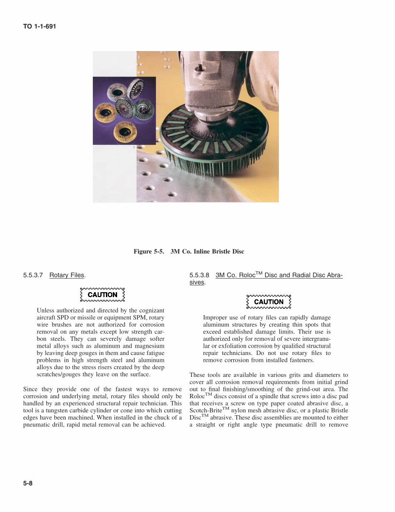
5.5.3.7 Rotary Files.
Unless authorized and directed by the cognizantaircraft SPD or missile or equipment SPM, rotarywire brushes are not authorized for corrosionremoval on any metals except low strength car-bon steels. They can severely damage softermetal alloys such as aluminum and magnesiumby leaving deep gouges in them and cause fatigueproblems in high strength steel and aluminumalloys due to the stress risers created by the deepscratches/gouges they leave on the surface.
Since they provide one of the fastest ways to removecorrosion and underlying metal, rotary files should only behandled by an experienced structural repair technician. Thistool is a tungsten carbide cylinder or cone into which cuttingedges have been machined. When installed in the chuck of apneumatic drill, rapid metal removal can be achieved.
5.5.3.8 3M Co. RolocTM Disc and Radial Disc Abra-sives.
Improper use of rotary files can rapidly damagealuminum structures by creating thin spots thatexceed established damage limits. Their use isauthorized only for removal of severe intergranu-lar or exfoliation corrosion by qualified structuralrepair technicians. Do not use rotary files toremove corrosion from installed fasteners.
These tools are available in various grits and diameters tocover all corrosion removal requirements from initial grindout to final finishing/smoothing of the grind-out area. TheRolocTM discs consist of a spindle that screws into a disc padthat receives a screw on type paper coated abrasive disc, aScotch-BriteTM nylon mesh abrasive disc, or a plastic BristleDiscTM abrasive. These disc assemblies are mounted to eithera straight or right angle type pneumatic drill to remove
Figure 5-5. 3M Co. Inline Bristle Disc
TO 1-1-691
5-8

corrosion from all types of readily accessible metal surfaces.The radial type plastic Bristle DiscTM is similar to a flapwheel and is mounted to an arbor either by itself or inmultiples with the assembly being installed in a straight typepnuematic drill to remove corrosion from all types of metalsurfaces, particularly in bores and recessed areas. To achievemaximum effectiveness with these discs, use at the specifiedRPM, and never exceed the maximum RPM rating specifiedon the disc to prevent disintegration of the disc during use andeither damage to equipment or injury to personnel.
5.5.4 Abrasive Blasting.
Abrasive blasting operations create airborne par-ticles which may be hazardous to the skin andeyes. A hood, gloves with gauntlets, and adequateventilation are required.
In abrasive blasting, abrasive media is propelled toward thework piece either with air pressure (conventional or vacuumblasting) or with water (wet blasting).
5.5.4.1 Conventional Equipment. Two types of equip-ment are used to propel dry abrasives: direct pressure feed
and suction/venturi feed. In direct pressure equipment, theabrasive holding tank is a pressure vessel from whichabrasive media is forced, through a metering device, into thepressurized blast line to the blast nozzle. In suction/venturifeed equipment, the abrasive holding tank is unpressurizedand provides media, through a metering device, into a passingair stream which then propels it through the blast hose to theblast nozzle. Small blast cabinets known as glove boxes (referto Figure 5-6, A) are built to accommodate small parts andhave a recycle system which removes dust and light particlecontaminants such as paint chips or corrosion products.Blasting rooms, designed for large components, use a recy-cling and ventilating system. The operator works within theroom, using a blast gun.
NOTE
Suction/venturi feed equipment requires highernozzle pressure than direct pressure equipment toobtain the required abrasive action. Pressuresgiven in Table 5-3 are for direct pressure equip-ment. As a general rule, increase the nozzlepressure by 50 percent when using suction/ven-turi feed equipment.
TO 1-1-691
5-9

Figure 5-6. Abrasive Blasting Equipment
TO 1-1-691
5-10

Table 5-3. Recommended Powered Abrasives for Corrosion Removal
Abrasive Blasting Parameters
AlloyFlap Brush, Abra-
sive Wheels (1)Abrasive Cloth/
Paper (2) Media (3) Pressure (PSI) Other Tools
Aluminum alloys(Clad)
Aluminum oxideor silicon car-bide
Aluminum oxideor silicon car-bide
Glass beads (Sizes 10-13) or (AGB-15, 12, 9,or 6)
30-40 (4) None
Aluminum alloys(Non-clad)
Aluminum oxideor silicon car-bide
Aluminum oxideor silicon car-bide
Glass beads (Sizes 10-13) or (AGB-15, 12, 9,or 6)
40-45 (4) Rotary files (finefluted)
Magnesium alloys Aluminum oxideor silicon car-bide
Aluminum oxideor silicon car-bide
Glass beads (Sizes 10-13) or (AGB-15, 12, 9,or 6)
10-35 (4) Rotary files (finefluted)
Ferrous metals(other thanstainless steel)
Aluminum oxideor silicon car-bide
Aluminum oxideor silicon car-bide
Aluminum oxide (Type I,Grade A or B); Glassbeads (sizes 10-13) or(AGB-15, 12, 9, or 6)
40-50 (4) 40-50(4)
Rotary files,Wire wheels(steel or stain-less steel)
Stainless steel andNickel alloys
Aluminum oxideor silicon car-bide
Aluminum oxideor silicon car-bide
(5)Glass beads (Sizes10-13) or (AGB-15,12, 9, or 6)
40-50 (4) Wire wheels(stainlesssteel) Rotaryfiles (finefluted)
Copper alloys DO NOT USE POWERED ABRASIVE METHODS DUE TO TOXICITY OF RESIDUE/PAR-TICLES GIVEN OFF - IN PARTICULAR FROM BERYLLIUM-COPPER ALLOYS.
Powered abrasive operations on titanium alloys can generate severe sparking. Keep areaclear of all ignitable substances when performing powered abrasive operations on titaniumalloys.
Titanium alloys Aluminum oxideor silicon car-bide
Aluminum oxideor silicon car-bide
Glass beads (Sizes 10-13) or (AGB-15, 12, 9,or 6); Aluminum oxide(Type I, Grade A or B)
40-50 (4) 40-50(4)
None
Plated and phos-phated surfaces
DO NOT USE POWERED ABRASIVE METHODS DUE TO TOXICITY OF RESIDUE/PAR-TICLES GIVEN OFF FROM MANY TYPES OF PLATING AND PROBABLE SEVEREDAMAGE TO VERY THIN PLATING FILMS.
(1) This includes RolocTM type discs and inline and radial type Bristle DiscsTM.(2) This includes RolocTM type discs.(3) Media specifications: Glass beads - AMS 2431/6 Aluminum oxide - A-A-59316(4) Indicated pressure is for direct pressure equipment. For suction/venturi equipment, use 50% higher pressure.(5) Use only on heavily corroded parts prior to acid pickling and/or passivation.
TO 1-1-691
5-11

Table 5-4. Recommended Non-Powered Abrasives for Corrosion Removal
Alloy Non-woven Abrasive Abrasive Cloth/Paper Metallic Wool Brushes Others
Aluminumalloys
Abrasive Mat Aluminum oxide,Silicon carbide
Aluminum wool Stainless steel,Aluminum
Pumice paste,Carbide-tippedscrapers
Magnesiumalloys
Abrasive Mat Aluminum oxide,Silicon carbide
None Stainless steel,Aluminum
Pumice paste,Carbide-tippedscrapers
Ferrous met-als (otherthan stain-less steel)
Abrasive Mat Aluminum oxide,Silicon carbide
Steel wool Carbon steel,Stainless steel
Carbide-tippedscrapers
Stainless steeland Nickelalloys
None Aluminum oxide,Silicon carbide
Stainless steel wool Stainless steel,Aluminum
None
Copper alloys None Aluminum oxide(400 grit), Siliconcarbide (400 grit)
Copper wool Brass None
Titanium al-loys
Abrasive Mat Aluminum oxide,Silicon carbide
Stainless steel wool Stainless steel,Aluminum
Pumice paste,Carbide-tippedscrapers
Cadmium orZinc platedsurfaces
Abrasive Mat Aluminum oxide,Silicon carbide
None None None
Chromium,Nickel, Tin,or copperplated sur-faces
Abrasive Mat Aluminum oxide,Silicon carbide
None Stainless steel,Aluminum
None
Phosphatedsurfaces
USE METHOD RECOMMENDED FOR BASE METAL
5.5.4.1.1 Blast Media. A wide variety of materials invarious sizes (measured by mesh or grit size) are available forblasting applications. Only aluminum oxide per A-A-59316,Type I, Grades A or B and glass beads per AMS 2431/6,Designation Nos. 15, 12, 9, and 6 (sizes 10-13) abrasives areapproved for use on aircraft, missiles, and their components.Other media may be used on steel components of supportequipment as designated in TO 35-1-3 and/or the equipmentsystem specific maintenance manual.
5.5.4.1.2 Air Hoses. The nozzle pressure of a blaststream is affected by the length and inside diameter (ID) ofthe air hoses. It is best to use the shortest hose possible toprevent excessive pressure drop due to friction. If it isnecessary to couple lengths of hose, use quick disconnectexternal couplers.
5.5.4.1.3 Blast Nozzles. In general, larger nozzle sizesare preferable to smaller ones, because more area can becleaned per hour with the same amount of labor. Highefficiency, wear resistant nozzles (e.g. tungsten carbide)should be used, since they have a longer service life anddirect the blasting particles more efficiently. Inspect nozzles
periodically for wear and discard them when the orifice isworn to a diameter which is 50 percent greater than thediameter when new. A worn nozzle, just as a larger nozzle,will require a larger volume of air flow from the compressorto sustain the needed pressure at the nozzle.
5.5.4.1.4 Air Supply. Frictional losses in the hosesreduce the pressure at the nozzle, and nozzle wear increasesthe volume of air needed to maintain the desired nozzlepressure. To allow for nozzle wear, it is generally goodpractice to use a compressor with the capability of deliveringat least 1½ times the cubic feet per minute (CFM) of airrequired for a new nozzle to permit adjustments as the nozzlewears. Moisture and oil in the air stream gradually accumu-lates in the abrasive during blasting operations and willeventually cause the abrasive to clog the blaster. A water andoil separator must be used in the compressed air supply lineto prevent this problem.
5.5.4.2 Portable Vacuum Abrasive Blast Equip-ment. Also known as vacu-blasters or dry honing ma-chines, these devices are portable machines designed torecover the abrasive as it rebounds from the work piece.
TO 1-1-691
5-12 Change 1

Vacu-blasters have an abrasive hopper, a reclaimer, a dustcollector, a vacuum pump, and a blast gun which containsboth a blast nozzle and a vacuum duct surrounding the nozzlefor recovery of the media (refer to Figure 5-6 B). Thisequipment is useful only on flat or slightly curved surfaces sothat the rebounding media can be collected by the vacuumduct surrounding the blast nozzle. Refer to TO 35-1-3, theequipment operators manual, and systems specific mainte-nance manuals for the aircraft, missile, or equipment beingrepaired for further information on the authorization and useof these machines.
5.5.4.3 Wet Abrasive Blasting Equipment. Wet abra-sive blasters use high pressure water as the medium for thedelivery of abrasives. This method is not as harmful to thebase metal as dry abrasive blasting due to the cushioningeffect of the water medium. Unfortunately, this effect inhibitsthe speed with which corrosion products are removed, and thewater can be driven into joint areas and cause corrosion itself.For these reasons, this method should not be used on aircraftor missiles. Wet abrasive blasters are useful for removing rustfrom steel surfaces of support equipment. The abrasivematerial is normally not recoverable in wet blasting opera-tions, and only sand per A-A-59316, Types II or VI, GradesB or C; aluminum oxide per A-A-59316, Type I, Grades A orB; or glass beads per AMS 2431/6, Designation No. AGB-6(size 13) shall be used. A corrosion inhibitor must be added tothe water or a temporary protective film such as a CorrosionPreventive Compound (CPC) must be applied to the blastedsurface immediately after blasting to prevent rusting of thesteel surface until the part can be painted.
5.6 SURFACE FINISH.
All depressions resulting from corrosion removal shall beblended smoothly and evenly with the surrounding originalsurfaces. In critical and highly stressed areas, all pits remain-ing after removal of corrosion products, by any method, shallbe blended out to prevent stress risers which may becomestarting points for stress corrosion cracking and/or metalfatigue. On non-critical structures, it is not necessary to blendout pits remaining after removal of corrosion products sincethis can result in unnecessary metal removal. Always checkthe system specific aircraft, missile, or equipment mainte-nance/repair manuals for maximum allowable depth of de-pressions due to pitting or corrosion removal. The generalguidelines for shaping and blending corrosion grind-outs areshown in Figure 5-7 through Figure 5-9. For additionalinformation on blend out procedures, refer to the systemspecific aircraft, missile, or equipment maintenance manualsand/or contact the aircraft SPD or the missile or equipmentSPM.
5.7 PITTING ON CRITICAL STRUCTURE.
On critical structures having a large number of closely spacedpits, intervening material may be removed to minimizesurface irregularity or waviness. The resulting depressionshall have no sharp corners and shall be saucer-shaped,wherever clearance permits, with its major axis running
spanwise on wings and horizontal stabilizers, longitudinallyon fuselages, and vertically on vertical stabilizers (refer toFigure 5-7). In areas where a true saucer shaped depressioncannot be formed due to inadequate clearance, blend out adepression as nearly as possible to that shape so that there areno abrupt or sharp edges.
5.8 CORROSION REMOVAL PROCEDURES-MECHANICAL.
5.8.1 Warnings and Cautions. The following warningsand cautions shall be observed during corrosion removaloperations.
5.8.1.1 Personal Protection.
• Many materials such as copper alloys (espe-cially beryllium-copper, refer to Paragraph7.20), cadmium plate, chromate conversioncoatings, paints containing chromates, lead,barium, and strontium, and chemicals used forcorrosion removal are toxic. Use approvedrespirators, eye protection, and skin protec-tion. Take proper safety precautions to avoidinhalation or ingestion of chemical fumes orliquids and dust from corrosion products dur-ing corrosion removal. Wash hands thoroughlybefore eating or smoking.
• All powered mechanical corrosion removalprocedures create airborne particles. Respira-tors and eye protection and adequate ventila-tion are required.
• It is essential that all blasting media and otherresidue be completely removed after abrasiveblasting operations. The blasting media can bevery slippery and can cause dangerous falls.
• Operators shall be adequately protected withcomplete face and head covering equipment,and provided with pure breathing air perrequirements of AFOSH Standards 91-31 and161-1 for all abrasive blasting operations .
• Wear leather gloves when using metallicwools to prevent hand injuries.
TO 1-1-691
Change 1 5-13

• Do not use abrasive flap brushes, wheels, discsor wire brushes above their authorized RPMrating. These tools can fly apart, causingserious injury.
• Abrasive blasting operations create extensiveairborne particles which may be hazardous tothe eyes, lungs, skin, etc. A hood, gloves withgauntlets, and respirator are required.
• Exercise caution when using sharp or pointedtools to prevent injury.
• Depleted uranium is extremely toxic and shallbe worked only under a license from theNuclear Regulatory Agency (NRA). Machin-ing or other work, such as surface sanding,may be done only by the licensee. No drilling,sanding, abrasive blasting, or other mechani-cal work is permitted on depleted uranium byany field level (organizational or intermediate)maintenance activity. If the protective finish(plating) which covers the depleted uranium ischipped, peeled, or otherwise removed so thedark gray or black uranium oxide is visible,the part must be returned to the licensee forrework or disposal. Packaging and shippingprocedures shall conform to AFI 40-201 andother any other related current regulations forhandling radioactive materials.
TO 1-1-691
5-14 Change 1

Figure 5-7. Shaping Reworked Areas
Figure 5-8. Acceptable Clean-up of Pitting Corrosion on Critical Structure
TO 1-1-691
5-15

5.8.1.2 Mechanical Damage.
• Use extreme care to ensure that blast mediadoes not contaminate hydraulic, fuel, oil, cool-ant, or oxygen systems. Blockages in flightcritical components caused by abrasive mediaparticles can result in loss of life and aircraft.
• Finely divided dried particles of many mate-rials (metallic, organic, and inorganic) canform explosive mixtures with air resulting indust explosion hazards. Use extreme carewhen dry abrasive blasting magnesium andtitanium alloys, and provide adequate ventila-tion to prevent formation of explosive dustmixtures during all abrasive blasting opera-tions.
• Abrasive blasting operations of these surfacesshall not be subjected to severe abrasive ac-tion. Do not use rotary files to remove corro-sion from installed fasteners.
• Use only non-powered abrasive paper, cloth,or mat, powered flap brushes or wheels, orabrasive blasting to remove corrosion fromhigh steels. Other power tools can cause localoverheating and/or formation of notcheswhich can generate fatigue or stress corrosioncracking failures. Refer to TO 4S-1-182 foradditional procedures/restrictions to be usedon aircraft landing gear components.
• Dry abrasive blasting of titanium alloys andhigh strength steel crates sparking. Ensure thatthe abrasive blasting area is free of all flam-mable vapors and liquids.
• Do not use flap brushes down to within twoinches from the center of the hub. Continueduse beyond this limit may cause gouging dueto loss of flexibility of the fiber. Followdirection of rotation, as indicated by arrowimprinted on side surface of the core.
• Excessive pressure on flap brushes will causepolyurethane paint to melt, gum up, and streakaround the area being worked
• Protect areas adjacent to corrosion removaloperations from chips, dust, and other debriswhich could produce dissimilar metal corro-sion on previously uncorroded surfaces.
• Use only those materials recommended inTable 5-3 and Table 5-4 to prevent dissimilarmetal particles from becoming embedded insurfaces and generating rapid galvanic corro-sion.
• Be careful when removing corrosion from softplated surfaces (zinc, cadmium, etc.). Softplating is easily damaged or removed bymechanical methods.
5.8.2 Non-Powered Mechanical Corrosion Re-moval. This method is accomplished by abrading thecorroded surface with hand held tools or abrasives to removethe corrosion. It is normally used to remove surface corrosionand other forms of mild to moderate corrosion by scraping orwearing away the corrosion products along with a minoramount of base metal. The basic steps in this procedure are.
5.8.2.1 Determine whether all the corrosion can be re-moved without exceeding the allowable damage limits before
Figure 5-9. Limited Clearance
TO 1-1-691
5-16

starting the removal operation. If damage limits will beexceeded, repair or replace the part per directions in theapplicable system specific aircraft, missile, or equipmentmaintenance manual or request disposition from the aircraftSPD or the missile or equipment SPM if repair or replace-ment is not covered in the manuals.
5.8.2.2 Protect adjacent components and/or areas fromscale, chips, corrosion products, and chemical agents. Masklap joints, hinges, faying surfaces, access doors, air scoops,and other openings which would allow chips, dust, or otherdebris to enter interior areas. Use barrier material/paper andmasking tape.
a. Clean the affected area to remove grease, oil, and soils(refer to Chapter 3).
b. Using materials in Table 5-4, remove all corrosion usingthe mildest effective method. Determine whether corro-sion has been completely removed by inspecting with a10X magnifier (refer to Appendix B). If necessary, amore sensitive evaluation can be made by using fluo-rescent penetrant in conjunction with the magnifier.
c. When complete removal has been attained, blend or fairout the edges of the damaged areas using fine abrasivepaper or cloth. After all corrosion has been removed,recheck to ensure that allowable damage limits have notbeen exceeded.
d. Treat the surface in accordance with Section II of thisChapter and apply protective coatings in accordancewith TO 1-1-8 and the applicable system specificmaintenance manual.
5.8.3 Powered Mechanical Corrosion Removal.Powered corrosion removal is generally done using pneu-matic drills with flap brush, rotary file, sanding pad orabrasive wheel attachments. This method is normally used toremove heavy corrosion by wearing away the corrosionproducts. Part of the base metal is abraded away with thecorrosion products using this procedure. The basic steps incorrosion removal are:
5.8.3.1 Determine whether all the corrosion can be re-moved without exceeding the allowable damage limits beforestarting the removal operation. If damage limits will beexceeded, repair or replace the part per directions in theapplicable system specific aircraft, missile, or equipmentmaintenance manual or request disposition from the aircraftSPD or the missile or equipment SPM if repair or replace-ment is not covered in the manuals.
5.8.3.2 Protect adjacent components and/or areas fromscale, chips, corrosion products, and chemical agents. Masklap joints, hinges, faying surfaces, access doors, air scoops,and other openings which would allow chips, dust, or otherdebris to enter interior areas. Use barrier material/paper andmasking tape.
a. Clean the affected area to remove grease, oil, and soils(refer to Chapter 3).
b. Using materials in Table 5-3, remove all corrosion usingthe mildest effective method. Determine whether corro-sion has been completely removed by inspecting with a10X magnifier (refer to Appendix B). If necessary, amore sensitive evaluation can be made by using fluo-rescent penetrant in conjunction with the magnifier.
c. When complete removal has been attained, blend or fairout the edges of the damaged areas using fine abrasivepaper or cloth.
d. After all corrosion has been removed, recheck to ensureallowable damage limits have not been exceeded.
e. Treat the surface in accordance with Section II of thisChapter and apply protective coatings in accordancewith TO 1-1-8 and the applicable system specificmaintenance manual.
5.8.4 Abrasive Blasting Corrosion Removal. Beforebeginning abrasive blasting operations, ensure that all safetyprecautions listed in the warnings and cautions in Paragraph3.5.1.2 and Paragraph 5.8.1.2 are fully observed. Failure tocomply with these precautions may result in harm to person-nel and equipment.
5.8.4.1 Abrasive Blasting Procedures. The blastingoperation should be accomplished in the following steps:
a. Inspect corroded areas and surfaces and decide whichones can be abrasively blasted and what techniques willbe used. Clean any oil, grease, or other soils fromsurfaces with MIL-PRF-87937, Type IV; MIL-PRF-85570, Type II; or an approved cleaning solvent such asA-A-59601 and/or MIL-PRF-680, Types II or III perinstructions in Chapter 3 of this manual.
(1) Blasting shall not be used in areas or under condi-tions that would allow any escaped abrasive particlesto contaminate any system, engine, or other compo-nent.
(2) Examine all corroded areas for corrosion blisters. Ifintergranular and/or exfoliation corrosion is present,use other recommended mechanical removal meth-ods. Abrasive blasting will not remove these types ofcorrosion effectively.
(3) Blasting shall not be performed on surfaces wherethere is a danger of warping or distorting the basematerial. Sheet metal, 0.0625 inch (16 gauge, U.S.Standard) or thinner shall not be blasted. Consult theapplicable system specific aircraft, missile, or equip-ment manuals to determine metal type, thickness,and allowable metal removal limits for the particularpart.
TO 1-1-691
Change 1 5-17

b. Determine what areas need protection from the mediablast stream and entrapment of the media, and mask orseal these areas. Composite surfaces and those requiringa very smooth surface finish (63 RMS or better) must beeffectively protected from the media blast stream. Useform fitting metal or wood shields as required and animpact resistant tape such as 3M Co. PN 510 or YR-500.
c. Statically ground the abrasive blast equipment and theaircraft, missile, or equipment to be blasted.
d. Blast corroded areas using the pressures and materialsgiven in Table 5-3. Do not attempt to use pressureshigher than those specified, since higher air pressurestend to cause significant damage to components byrapidly removing too much surrounding metal alongwith the corrosion products. When cleaning non-ferrousmetal alloys (i.e. aluminum, magnesium, etc.), never usemedia which has been used for cleaning ferrous metals.Abrasives used for cleaning ferrous metals will retainmany ferrous metal particles which will contaminateany non-ferrous metal being blasted. Refer to theapplicable abrasive blasting equipment operator’smanual for specific operating instructions.
(1) Direct the blast stream at the surface from whichcorrosion is being removed to sweep across thesurface at an angle of 30° to 40° from the blastnozzle to the surface. Several short passes over thecorroded area with the blast nozzle are much moreeffective and less damaging to the surrounding metalthan dwelling on an area for an extended period oftime. Passes should start a few inches before and enda few inches beyond the corroded area being worked.
(2) Maintain the nozzle distance from the surface beingclean wherever the best cleaning is obtained withinthe range of 2 inches minimum to 6 inches maxi-mum.
(3) Continue blasting with short passes over the cor-roded area until a near-white metal surface is ob-tained. A near-white metal surface is a surface fromwhich all mill scale, rust, oxides, any other types ofcorrosion products, paint, and/or any other foreignmatter have been removed.
(4) On critical high strength aluminum and steel parts, itis necessary to fair out and smooth edges of pits toreduce stress concentrations that generate metal fa-tigue and/or stress corrosion cracking problems. Themost effective manner is to rotate the blast nozzlearound the outer edge of the pit, keeping the nozzleat a constant rate using several short passes over thecorroded area.
e. Upon completion of blasting, inspect for the presence ofcorrosion in the blasted area. It may be necessary to usefluorescent penetrant inspection in conjunction with a10X magnifier. Pay particular attention to areas where itis suspected that pitting has progressed into intergranu-
lar attack, because abrasive blasting has a tendency toclose up streaks of intergranular corrosion rather thanremove them if e. the operator uses an improperimpingement angle. If corrosion has not been removedin a total blasting time of 60 seconds on any one specificarea, other mechanical methods of removal should beutilized.
NOTE
• Refer to the individual system specific aircraft,missile, or equipment maintenance manualsfor limits on metal removal. Do not exceedthese limits without engineering approvalfrom the aircraft SPD or the missile or equip-ment SPM.
• Abrasive blasting will not remove intergranu-lar and/or exfoliation corrosion from alumi-num alloys.
• Abrasive blasting shall be used on stainlesssteel (CRES) and nickel alloy parts only toremove severe/heavy corrosion and prior toacid pickling and/or passivation.
f. Completely clean all residue from the surface andexposed areas using either a pneumatic or an electricwet/dry vacuum cleaner. The vacuum cleaner nozzleshall be plastic or covered with masking tape to protectsurfaces from mechanical damage. Clean the surfaceusing materials and procedures in Chapter 3. Treat andprotect all blasted areas as soon as possible after blastingin accordance with the procedures in Section II of thisChapter.
5.9 CORROSION REMOVAL-CHEMICAL.
The following paragraphs discuss chemical removal proce-dures for use on aircraft, missile, and other equipmentparts/components and assemblies. Each type of metal alloyrequires specific chemicals for removal of the different typesof corrosion that are encountered on the metal alloy. Theauthorized chemical corrosion removal materials and proce-dures for their usage for each of the various metal alloys usedon Air Force aircraft, missiles, and equipment is discussedseparately for each metal alloy.
5.9.1 Aluminum Alloys. These paragraphs outlinechemical corrosion removal procedures for aluminum alloyparts and assemblies of aircraft, missiles, and other equip-ment. Table 5-5 provides procedures for removal of specifictypes of corrosion.
5.9.1.1 Preparation. Before starting chemical removalof corrosion products, perform the following procedures:
a. Clean all dirt, grease, oil, and other contamination fromsurfaces to be worked in accordance with Chapter 3.
TO 1-1-691
5-18 Change 1

b. Inspect the equipment to determine which area(s) areand should be treated with a chemical corrosion removalcompound. If an aircraft is being prepared for completepainting or repainting, all cleaned bare aluminum sur-faces shall be treated.
• Protect all magnesium surfaces from contactwith SAE AMS-1640 (MIL-C-38334) corro-sion removal compound and treat later, asprescribed in this manual. Steel and cadmiumplated parts should also be protected from thiscompound, but protection of all steel andcadmium plated steel fastener heads in largestructures is impractical and need not be done.
• Do not allow these chemical corrosion remov-ers to contact high strength steel. Hydrogenembrittlement may occur and cause a cata-strophic failure.
c. Mask all lap joints, hinges, faying surfaces, accessdoors, air scoops, and other openings that would allowthe corrosion removal compound to enter interior areasor crevices, or contact unprotected magnesium, steel,and cadmium plated parts. Mask with MIL-PRF-131,Class 1 water and vapor proof barrier material (plasticside toward the surface) and SAE AMS-T-23397, TypeII (MIL-T-23397, Type II) masking tape. 3M Co. PN425 tape is the most effective tape for extensive opera-tions, such as chemical corrosion removal and surfacepreparation on large structures such as aircraft exteriorsduring depot repaint operations.
5.9.1.2 Chemical Corrosion Removal Materials forAluminum Alloys. SAE AMS-1640 (MIL-C-38334, TypeI) Corrosion Removal Compound for Aircraft Surfaces is theauthorized general chemical remover for removing corrosionproducts from aluminum alloys, in particular on larger areas.Limited area corrosion removal can also be accomplished byusing MIL-DTL-81706, Class 1A chemical conversion coat-ing solution or Semco® PN Pasa-Jell 102 gel type aluminumcorrosion remover in conjunction with A-A-58054, Type I,Grade B or C abrasive mats.
5.9.1.2.1 SAE AMS-1640 (MIL-C-38334, Type I) Cor-rosion Removing Compound for Aircraft Surfaces.
SAE AMS-1640 (MIL-C-38334, Type I) andSemco® PN Pasa-Jell 102 are moderately toxicand MIL-DTL-81706, Class 1A is highly toxic toskin, eyes, and respiratory tract. Chemical orsplash proof goggles and/or face shields, andchemical resistant rubber gloves, and aprons arerequired. Good general ventilation is normallyadequate.
This material is a liquid concentrate material which shall bemixed with an equal volume of tap water before use; furtherdilution renders it ineffective. This material has a shelf life ofone year from the date of manufacture; discard any of thematerial which has reached or exceeded its shelf life. SAEAMS-1640 (MIL-C-38334, Type I) is used as a generalchemical corrosion remover to remove surface and pittingcorrosion products from aluminum alloy surfaces. It is notLiquid Oxygen (LOX) compatible.
5.9.1.2.1.1 Application and Use. The procedure forapplication and use of SAE AMS-1640 (MIL-C-38334, TypeI) materials is as follows:
a. After mixing properly, apply the solution by eitherflowing, mopping, sponging, brushing, wiping, or spray-ing with a non-atomizing sprayer onto the surface beingworked. For large areas, begin the application at thelowest point and work upward while using a circularmotion to apply the solution to ensure proper coverageand to disturb the oxide film on the surface.
b. Allow the solution to dwell on the surface for 11 to 12minutes while vigorously agitating it on the surface atleast every 2 minutes with a non-metallic, acid resistant,bristle brush or an A-A-58054, Type I, Grade B or Cabrasive mat. Then rinse the surface thoroughly withfresh water heated to a temperature of +120° to +140° F(+49° to +60° C). The solution is much more effective ifit is also heated to a temperature of +120° to +140° F(+49° to +60° C) and applied while warm. For severepitting, removal may be aided by lightly agitating thepits by hand with a stainless steel (CRES) wire bristlebrush with wire bristles having a maximum diameterbetween 0.005 and 0.006 inch (5-6 mils). Areas with
TO 1-1-691
Change 1 5-19

moderate to heavy surface or pitting corrosion mayrequire additional applications.
c. After each solution application and rinse, examine thearea being worked, aided with a 10X magnifier forpitting, to determine if all corrosion products have beenremoved. If not, repeat this process a maximum of threemore times. If corrosion products remain after the fourthapplication of this chemical remover, use an appropriatemechanical method described in this Chapter to removethe remaining corrosion products.
NOTE
(MIL-DTL-81706)/MIL-DTL-5541, Class 1Achemical chromate conversion coating shall beapplied immediately after the final rinse whencorrosion removal is the last process of a reworkoperation, or when the item or area will bepainted.
Table 5-5. Typical Chemical Corrosion Removal Procedures For Aluminum Alloy Parts and Assemblies
Type of CorrosionStep 1
Corrosion Removal
Step 2Surface Treatment (When ap-
plicable)
Step 3Final Protective Paint
Finish (When applicable)
Light or heavy pitting oretching of aluminum al-loys (clad)
Remove corrosion withSAE AMS-1640 (MIL-C-38334, Type I) per Para-graph 5.9.1.2.1.
MIL-DTL-81706/MIL-DTL-5541, Class 1A per SectionII of this chapter.
See TO 1-1-8 and air-craft, missile, or equip-ment system specificmaintenance manualsfor paint system
Light or heavy pitting oretching of aluminum al-loys (non-clad)
Remove corrosion withSAE AMS-1640 (MIL-C-38334, Type I) perParagraph 5.9.1.2.1 fol-lowed by appropriate me-chanical methods in thischapter if necessary.
As above As above
Intergranular or exfoliationcorrosion of aluminumalloys
Not applicable. Removecorrosion by appropriatemechanical methods inthis chapter.
As above As above
Light or heavy pitting oretching on small alumi-num alloy parts whichcan be removed for treat-ment
Remove corrosion and/oroxide film by immersionin a SAE AMS-1640(MIL-C-38334, Type I)prepared per Paragraph5.9.1.2.1.
Immersion in MIL-DTL-81706, Class 1A solutionper Section II of this chap-ter.
As above
Stress corrosion cracking ofaluminum
Not applicable; replace/re-pair as required in thestructural handbook
See step 1 See step 1
5.9.1.2.2 Semco® PN Pasa-Jell 102. This material isa gel type chemical corrosion remover for use on aluminumalloys in limited areas, in particular where LOX compatibilityis required, to remove pitting and surface corrosion oretching/oxidation. Pasa-Jell 102 is a relatively strong acidmixture that can be detrimental to equipment or componentsif improperly used. Therefore, it shall be used only in small
areas, and primarily where LOX compatibility is an essentialrequirement. Personnel must be properly trained and qualifiedto use this material for corrosion removal.
5.9.1.2.2.1 Application and Use.
TO 1-1-691
5-20 Change 1

Do not use aluminum or any type of steel wool toapply or agitate Semco® PN Pasa-Jell 102 or firewill result.
Excessive use of abrasive materials and Semco®PN Pasa-Jell 102 can cause removal of protectivecladding (Alclad) and/or excessive metalremoval.
The procedure for application and use of Semco® PNPasa-Jell 102 material is as follows:
a. Apply Pasa-Jell 102 with an acid brush. Agitate areas ofdeep pitting with an acid brush that has the bristlesshortened by cutting off half their length or an A-A-58054, Type I, Grade A or B abrasive mat until corrosionproducts are removed. A thin, evenly dispersed filmgives the best results. Keep the dwell time to theminimum necessary to effectively remove the corrosionproducts (5 to 12 minutes). Usually, dwell time can becontrolled by closely observing the reaction of thePasa-Jell 102 mixture with the aluminum surface towhich it is applied to determine when all corrosionproducts have been lifted from the surface.
b. After all the corrosion products have been freed fromthe surface or the maximum 12 minutes dwell time isreached, whichever is first, wipe off the Pasa-Jell 102and other residue with a clean, moist cloth followed byrinsing with a stream of fresh tap water applied with awash bottle or continue to wipe with a clean, moistcloth, frequently rinsed in fresh tap water.
c. Inspect the area being worked to determine if allcorrosion has been removed giving particular attentionto pitted areas. Use a 10X magnifier to aid in examina-tion of questionable areas. Remaining corrosion willappear as a powdery crust, slightly different in colorthan the uncorroded base metal. One application ofPasa-Jell 102 is usually sufficient in most cases. How-ever, in severe cases, the preceding steps may have to berepeated.
5.9.1.2.3 MIL-DTL-81706, Class 1A Chemical Chro-mate Conversion Coating Solutions. Limited area cor-rosion removal from aluminum alloy surfaces while simulta-neously applying a chemical chromate conversion coatingcan be accomplished by using a MIL-DTL-81706, Class 1Asolution in conjunction with an A-A-58054, Type I, Grade Cabrasive mat. This material helps to clean an area byoxidizing all organic soils on the aluminum alloy surface,while the abrasive mat acts to remove the corrosion products,and then the solution forms a chemical chromate conversioncoating film on the aluminum alloy surface. If organic soilsare present, they will turn green upon application of the
solution. The green residue and the solution contaminatedwith the residue should be wiped from the surface anddiscarded. Mix the MIL-DTL-81706, Class 1A solution inaccordance with the manufacturer’s instructions and SectionII of this chapter. It is recommended that the technicianpractice on some condemned components or parts prior tousing this material on serviceable aircraft, missile, or equip-ment aluminum alloy parts.
5.9.1.2.3.1 Application of MIL-DTL-81706, Class 1ASolutions for Corrosion Removal.
MIL-DTL-81706, Class 1A chemical chromateconversion coating solutions are moderately toxicto the skin, eyes, and respiratory tract. Chemicalor splash proof goggles and chemical resistantrubber gloves are required. Good general venti-lation is normally adequate.
MIL-DTL-81706, Class 1A solutions shall not beused on high strength steels (180 KSI or higher),due to the potential of hydrogen embrittlement.Also, they shall not be used on magnesium,titanium, or cadmium or zinc plated parts/sur-faces as they will damage and/or corrode thesemetals.
The procedures for application of these materials for corro-sion removal are the same as those cited in Section II of thischapter for the standard chemical chromate conversion coat-ing solutions, except as follows:
a. The small area requiring corrosion removal and surfacetreatment can be cleaned with the chemical chromateconversion coating solution instead of cleaning, rinsing,and drying per Chapter 3 before application of thesolution.
b. Thoroughly wet or flood the area being worked with thesolution and keep it wet with solution until all phases ofthe process are completed and the final film is formed toprevent streaking and/or powdering on the surface.
c. Lightly abrade the surface while wet with the solutionusing a A-A-58054, Type I, Grade C abrasive mat.
d. If the solution turns green, continue to abrade the entirearea until it is completely cleaned, and then wipe alldirty solution from the surface with a sponge, whichshould leave a bright, shiny surface. If dark spots orlines are seen in the area which indicates the presence ofresidual spots of moderate to severe corrosion, reapplythe solution and vigorously agitate the wetted area withan abrasive mat as before. If the corrosion is notcompletely removed after this second application of
TO 1-1-691
Change 1 5-21
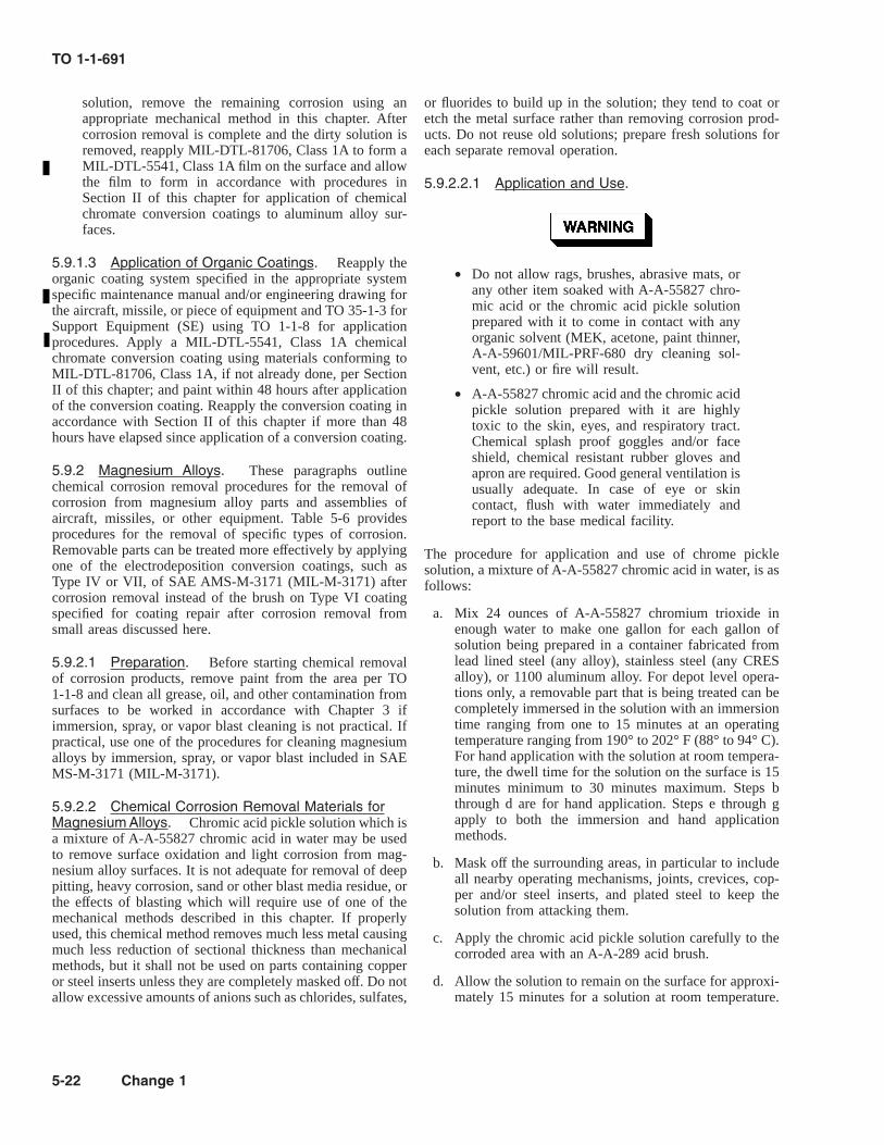
solution, remove the remaining corrosion using anappropriate mechanical method in this chapter. Aftercorrosion removal is complete and the dirty solution isremoved, reapply MIL-DTL-81706, Class 1A to form aMIL-DTL-5541, Class 1A film on the surface and allowthe film to form in accordance with procedures inSection II of this chapter for application of chemicalchromate conversion coatings to aluminum alloy sur-faces.
5.9.1.3 Application of Organic Coatings. Reapply theorganic coating system specified in the appropriate systemspecific maintenance manual and/or engineering drawing forthe aircraft, missile, or piece of equipment and TO 35-1-3 forSupport Equipment (SE) using TO 1-1-8 for applicationprocedures. Apply a MIL-DTL-5541, Class 1A chemicalchromate conversion coating using materials conforming toMIL-DTL-81706, Class 1A, if not already done, per SectionII of this chapter; and paint within 48 hours after applicationof the conversion coating. Reapply the conversion coating inaccordance with Section II of this chapter if more than 48hours have elapsed since application of a conversion coating.
5.9.2 Magnesium Alloys. These paragraphs outlinechemical corrosion removal procedures for the removal ofcorrosion from magnesium alloy parts and assemblies ofaircraft, missiles, or other equipment. Table 5-6 providesprocedures for the removal of specific types of corrosion.Removable parts can be treated more effectively by applyingone of the electrodeposition conversion coatings, such asType IV or VII, of SAE AMS-M-3171 (MIL-M-3171) aftercorrosion removal instead of the brush on Type VI coatingspecified for coating repair after corrosion removal fromsmall areas discussed here.
5.9.2.1 Preparation. Before starting chemical removalof corrosion products, remove paint from the area per TO1-1-8 and clean all grease, oil, and other contamination fromsurfaces to be worked in accordance with Chapter 3 ifimmersion, spray, or vapor blast cleaning is not practical. Ifpractical, use one of the procedures for cleaning magnesiumalloys by immersion, spray, or vapor blast included in SAEMS-M-3171 (MIL-M-3171).
5.9.2.2 Chemical Corrosion Removal Materials forMagnesium Alloys. Chromic acid pickle solution which isa mixture of A-A-55827 chromic acid in water may be usedto remove surface oxidation and light corrosion from mag-nesium alloy surfaces. It is not adequate for removal of deeppitting, heavy corrosion, sand or other blast media residue, orthe effects of blasting which will require use of one of themechanical methods described in this chapter. If properlyused, this chemical method removes much less metal causingmuch less reduction of sectional thickness than mechanicalmethods, but it shall not be used on parts containing copperor steel inserts unless they are completely masked off. Do notallow excessive amounts of anions such as chlorides, sulfates,
or fluorides to build up in the solution; they tend to coat oretch the metal surface rather than removing corrosion prod-ucts. Do not reuse old solutions; prepare fresh solutions foreach separate removal operation.
5.9.2.2.1 Application and Use.
• Do not allow rags, brushes, abrasive mats, orany other item soaked with A-A-55827 chro-mic acid or the chromic acid pickle solutionprepared with it to come in contact with anyorganic solvent (MEK, acetone, paint thinner,A-A-59601/MIL-PRF-680 dry cleaning sol-vent, etc.) or fire will result.
• A-A-55827 chromic acid and the chromic acidpickle solution prepared with it are highlytoxic to the skin, eyes, and respiratory tract.Chemical splash proof goggles and/or faceshield, chemical resistant rubber gloves andapron are required. Good general ventilation isusually adequate. In case of eye or skincontact, flush with water immediately andreport to the base medical facility.
The procedure for application and use of chrome picklesolution, a mixture of A-A-55827 chromic acid in water, is asfollows:
a. Mix 24 ounces of A-A-55827 chromium trioxide inenough water to make one gallon for each gallon ofsolution being prepared in a container fabricated fromlead lined steel (any alloy), stainless steel (any CRESalloy), or 1100 aluminum alloy. For depot level opera-tions only, a removable part that is being treated can becompletely immersed in the solution with an immersiontime ranging from one to 15 minutes at an operatingtemperature ranging from 190° to 202° F (88° to 94° C).For hand application with the solution at room tempera-ture, the dwell time for the solution on the surface is 15minutes minimum to 30 minutes maximum. Steps bthrough d are for hand application. Steps e through gapply to both the immersion and hand applicationmethods.
b. Mask off the surrounding areas, in particular to includeall nearby operating mechanisms, joints, crevices, cop-per and/or steel inserts, and plated steel to keep thesolution from attacking them.
c. Apply the chromic acid pickle solution carefully to thecorroded area with an A-A-289 acid brush.
d. Allow the solution to remain on the surface for approxi-mately 15 minutes for a solution at room temperature.
TO 1-1-691
5-22 Change 1

Agitate the area with an A-A-289 acid brush having halfthe bristle length cut off or an A-A-58054, Type I, GradeB or C abrasive mat.
e. Thoroughly rinse the solution from the surface withplenty of fresh tap water.
f. Repeat the preceding sequence as necessary until allcorrosion products have been removed and the metal isa bright metallic color.
g. Apply a SAE AMS-M-3171 (MIL-M-3171), Type VIchromic acid brush-on pretreatment coating to the areafrom which corrosion was removed in accordance withprocedures in Section II of this chapter for application ofa brush-on chromic acid pretreatment coating to mag-
nesium alloy surfaces. If desired, parts that were treatedby complete immersion may receive one of the othercoatings listed in SAE AMS-M-3171 (MIL-M-3171) fordepot level operations.
5.9.2.3 Application of Organic Coatings. Reapply theorganic coating system specified in the appropriate systemspecific maintenance manual and/or engineering drawing forthe aircraft, missile, or piece of equipment and TO 35-1-3 forsupport equipment (SE) using TO 1-1-8 for applicationprocedures. Apply the paint within 48 hours after applicationof the pretreatment coating. Reapply the pretreatment coatingin accordance with Section II of this chapter if more than 48hours have elapsed since application of the pretreatmentcoating.
Table 5-6. Typical Chemical Corrosion Removal Procedures for Magnesium Alloys
Type of Corrosion Step 1Corrosion Removal
Step 2Surface Treatment
Step 3Protective Finish
Light pitting or sur-face oxidation/etch-ing
Remove corrosion with chro-mic acid pickle solutionper Paragraph 5.9.2.2
SAE AMS-M-3171 (MIL-M-3171),Type VI per Section II of this chapter
Approved paint sys-tem per Paragraph5.9.2.3
Heavy pitting or etch-ing
Not applicable. Remove cor-rosion by an appropriatemechanical method in thischapter.
As above As above
Intergranular or exfo-liation
Not applicable. Remove cor-rosion by an appropriatemechanical method in thischapter.
As above As above
Light or heavy corro-sion on small partswhich can be re-moved for treatment
Remove corrosion in accor-dance with SAE AMS-M-3171 (MIL-M-3171)
As above As above
Stress corrosioncracking
Not applicable. Replace orrepair as required in thesystem specific structuralhandbook.
Not applicable Not applicable
5.9.3 Ferrous Metal (Steel) Alloys Other Than Stain-less Steels (Cres). These paragraphs outline chemicalcorrosion removal procedures for treating ferrous metal alloyparts and assemblies of aircraft, missiles, and other equip-ment. Use of chemical corrosion removers on steels isrecommended only for areas where there is no danger ofentrapping the chemicals in crevices and/or recesses. Table5-7 provides procedures for the removal of specific types ofcorrosion.
5.9.3.1 Preparation. Before starting chemical removalof corrosion products, remove paint from the area per TO1-1-8 and clean all heavy deposits of grease, oil, and othercontaminants from the surfaces to be worked in accordancewith Chapter 3.
5.9.3.2 Chemical Corrosion Removing Materials forFerrous Metal Alloys Other Than Stainless Steels(CRES). Chemical corrosion/rust removers for steels areof two types; the MIL-C-10578 acid type and the A-A-59260(MIL-C-14460) alkaline type.
5.9.3.2.1 MIL-C-10578 Corrosion Removing andMetal Conditioning Compound (Phosphoric AcidBase). MIL-C-10578 covers six separate types of phos-phoric acid based corrosion/rust removing compounds usedto remove corrosion/rust from ferrous metal surfaces. Thefollowing types are available:
TO 1-1-691
Change 1 5-23

5.9.3.2.1.1 Type I (Wash-Off) and II (Wipe-Off). TypeI and II materials are suitable as rust removers for ferrousalloy metal parts. They may also be used as metal condition-ers for ferrous and nonferrous (zinc galvanized, cadmium,brass, and relatively pure aluminum or alclad) metals prior tothe primer and paint application and/or as a corrosionpreventive to provide minor corrosion protection to thesemetals in an unpainted condition. Remove very heavy rustincrustations using an appropriate mechanical method listedin this chapter and heavy grease, oil, and other contaminationper Chapter 3 as directed by Paragraph 5.9.3.1 beforeapplication of these materials. Type I is a little more efficientin removing rust and grease than Type II. Type I materials areapplied by either spray, dip, flow-on, brush, rag, or spongeand are always rinsed off with water, preferably hot. Type IImaterials are applied by either brush, rag, or sponge and donot have to be rinsed off with water, but are wiped off withclean, damp rags followed by wiping with clean, dry ragsprior to painting. Type II materials leave a light, gray-whitecoating/film on the surface that acts as a pretreatment forpainting.
5.9.3.2.1.2 Type III (Inhibited). Type III materials areintended for corrosion/rust removal from chromium platedferrous alloy surfaces and those bare ferrous alloy surfacesrequiring very close dimensional tolerances. Remove veryheavy rust incrustations by an appropriate mechanical methodin this chapter, and heavy grease, oil, and contamination perChapter 3 as directed by Paragraph 5.9.3.1 or by vapordegreasing before application of these materials. Type IIImaterials are applied by either spray, dip, flow-on, brush or byfull immersion in a tank containing the material. Parts are leftin the solution tank or the solution is left on the surface of thepart until the rust is dissolved or loosened sufficiently topermit easy removal, and then the residue is rinsed off thesurface with fresh, tap water, preferably hot, and the part isdried. It is then ready for application of the required corrosionpreventive treatment or paint system application.
5.9.3.2.1.3 Type IV (Nonfoaming). Type IV materialsare very similar to Type I, except that nonfoaming detergentsare included in the mixture. It is intended for use inpressurized spray systems at temperatures up to 150° F (66°C) maximum, after which it is rinsed off with fresh, tap water.
5.9.3.2.1.4 Type V (Immersion Tank). Type V materi-als are also very similar to Type I, except no grease removingsolvents are used in these materials, so they are only suitablefor use on surfaces from which all grease, oil, and contami-nation have been completely removed by cleaning per Chap-ter 3 as directed by Paragraph 5.9.3.1. It is intended for use inimmersion tanks either at ambient temperatures or at tem-peratures up to 140° F (60° C) maximum.
5.9.3.2.1.5 Type VI (Brush, Spray, or Dip). Type VImaterials are surface pretreatments and/or rust converters forapplication on either newly sand blasted or corroded/rusty
steel surfaces by spray, brush, or dipping. All old grease, oil,and dirt must be removed as well as all loose and scaly rustbefore applying these materials. After application, they areallowed to dwell on the surface for a minimum of six hoursto form a pretreatment coating on uncorroded ferrous alloysor to convert the rust on a corroded ferrous surface to aprotective, pretreatment film. After a dwell time of six hours,the excess materials are rinsed off, the surface is allowed toair dry, and then the surface can be primed and painted ortreated with a CPC.
5.9.3.2.2 Application and Use of MIL-C-10578 Corro-sion Removing Compounds.
• Phosphoric acid corrosion removal com-pounds are toxic to the skin, eyes, and respi-ratory tract. Chemical splash proof gogglesand rubber gloves and aprons are required.Use only in a well ventilated area. In case ofeye or skin contact, flush immediately withwater and report to the Base Medical Facility.
• When mixing, always add the phosphoric acidcorrosion remover to the water. Do not add thewater to the acid, since this causes excessiveheat to be generated.
• High strength steel parts, those heat-treatedabove Rockwell C40 (180,000 PSI) tensilestrength, are subject to hydrogen embrittle-ment when exposed to acids, therefore, use ofacid rust/corrosion removers on these parts isprohibited.
• Do not use acidic rust/corrosion removers ifthere is a danger of entrapping the materials increvices or recesses, as they can cause corro-sion in these areas.
5.9.3.2.2.1 Application and Use of Type I (Wash-Off). The directions for application and use of thesematerials are as follows:
a. Add one part of the concentrated material as received tothree parts of water by volume. Use either a stainlesssteel, aluminum, vinyl, polyethylene, or rubber mixingcontainer.
b. Remove heavy grease, oil, and contamination per Chap-ter 3 and heavy rust using an appropriate mechanicalmethod in this chapter before applying the chemicalremoval compound.
TO 1-1-691
5-24

c. Protect adjacent components by masking to preventdamage by scale, chips, corrosion products, or chemi-cals.
d. Apply the solution to the surfaces to be treated by eithernon-atomized spray, dip, flow-on, or brush. Allow thematerial to remain only long enough to wet the surfaceand cause etching. On rusted surfaces, allow the solutionto dwell on the surface long enough to loosen the rust (2to 10 minutes, depending on the degree of rusting) whileagitating the surface with an A-A-58054, Type I, GradeC abrasive mat or a hand held stainless steel (CRES)brush.
e. Rinse the surface with fresh, tap water, preferably hot(120° - 140° F/ 49° - 60° C). Allow the surface to drythoroughly prior to application of a rust/CPC or arequired paint system.
5.9.3.2.2.2 Application and Use of Type II (Wipe-Off). The directions for application and use of thesematerials are as follows:
a. Add one part of the concentrated material as received tothree parts of water by volume. Use the same type ofmixing containers specified in Paragraph 5.9.2.2.1 , stepa.
b. Remove heavy grease, oil, and contamination per Chap-ter 3 and heavy rust using an appropriate mechanicalmethod in this chapter before applying the chemicalremoval compound.
c. Protect adjacent components by masking to preventdamage by scale, chips, corrosion products, or chemi-cals.
d. Apply the solution to the surfaces to be treated by eitherbrush, rag, or sponge. Allow the compound to dwell onthe surface for about 30 seconds.
e. Wipe off residue first with damp rags followed with dryrags leaving no more than a light gray-white coatingfilm on the surface. Allow the surface to dry thoroughlyprior to applying the required paint system.
5.9.3.2.2.3 Application and Use of Type III (Inhib-ited). The directions for application and use of thesematerials are as follows:
5.9.3.2.2.3.1 Follow these procedures for non-atomizedspray, flow-on, and brush applied operations with Type IIImaterials:
a. Add one part of the concentrated material as received toone part of water by volume. Use the same type ofmixing containers specified in Paragraph 5.9.2.2.1, stepa.
b. Remove grease, oil, and contamination per Chapter 3and heavy rust using an appropriate mechanical methodin this chapter prior to applying the chemical removalcompound.
c. Protect adjacent components by masking to preventdamage by scale, chips, corrosion products, or chemi-cals.
d. Apply the solution to the surfaces to be treated bynon-atomized spray, flow-on, or brush. Allow the con-ditioner to dwell on the surfaces long enough to loosenand/or dissolve the rust, and then rinse off all residuewith fresh, hot, tap water (120° - 140° F/ 49° -60° C).
e. Allow the surface to thoroughly dry, and then eitherapply a CPC or a required paint system, or place the partdirectly into service, whichever is directed by the systemspecific maintenance technical data for the equipmentinvolved.
Heated dip tanks shall be properly ventilated, andventilation shall be evaluated by the Bioenviron-mental Engineer prior to initial use.
5.9.3.2.2.3.2 Follow these procedures for dip tank opera-tions with Type III materials:
a. Stainless steel (CRES) tanks are preferred for use withthis method. Mix the material as specified for non-atomized spray, flow-on, and brush applications, but mixit in the stainless steel (CRES) dip tank.
b. Immerse the part in the solution only long enough toloosen the rust. For heavy rust removal, the solution canbe heated to 140° F (60° C) maximum.
c. Agitate the part in the solution to increase the rustremoval rate. Rinse in a continuously over-flowingfresh, cold, tap water rinse tank, if available, or spraywith fresh, hot, tap water (120° - 140° F/49° - 60° C).Thoroughly dry the parts and immediately apply therequired paint system or CPC or place the part directlyinto service, whichever is directed by the system specificmaintenance technical data for the equipment involved.
5.9.3.2.2.4 Application and Use of Type IV (Non-Foaming). The directions for application and use of thesematerials are as follows:
a. Add one part of the concentrated material as received tothree parts of water by volume. Use the same type ofmixing containers as specified in Paragraph 5.9.3.2.2.1,step a.
b. Remove all heavy grease, oil, and contamination perChapter 3 and heavy rust using an appropriate mechani-cal method in this chapter prior to applying the chemicalremoval compound.
c. Apply the solution to the surface being treated bynon-atomized, pressurized spray. To increase the rust
TO 1-1-691
Change 1 5-25

removal rate, the solution may be heated up to atemperature of 150° F (66° C).
d. Rinse with fresh, tap water, preferably hot (120° - 140°F/ 49° - 60° C).
e. Allow the part to thoroughly dry prior to application ofa rust/CPC or a required paint system.
5.9.3.2.2.5 Application and Use of Type V (Immer-sion Tank). The directions for application and use of thesematerials are as follows:
a. Add one part of the concentrated material as received tothree parts of water by volume. Use the same type ofmixing containers as specified in Paragraph 5.9.3.2.2.1,step a, and pour the solution into a stainless steel(CRES) immersion tank, or mix the solution directly inthe immersion tank.
b. This material contains no solvents to assist in cleaning,so all heavy grease, oil, and contamination must bethoroughly removed per Chapter 3 or immersion in analkali bath prior to immersing a part in the corrosionremoval solution. Remove heavy rust with an appropri-ate mechanical method in this chapter also prior toimmersion of the part in the chemical removal com-pound.
c. Submerge the part being treated in the chemical removalcompound just long enough to loosen the rust. Forheavy rust removal, the solution can be heated to atemperature of 140° F (60° C).
d. After immersion, rinse all metal surfaces thoroughlywith fresh, tap water, or immerse the part in an alkalisolution followed by rinsing with fresh, tap water.
e. Allow the part to thoroughly dry prior to applying aCPC or a required paint system.
5.9.3.2.2.6 Application and Use of Type VI (Brush,Spray, or Dip). The directions for application and use ofthese materials are as follows:
a. Add one part of the concentrated material as received tothree parts of water by volume. Use the same type ofmixing containers specified in Paragraph 5.9.2.2.1, stepa. This material is also available mixed in a pen typeapplicator for direct application to the surface.
b. Remove all heavy grease, oil, and contamination perChapter 3 and heavy rust using an appropriate mechani-cal method in this chapter prior to applying the chemicalremoval compound.
c. Apply the solution to the surface being treated by brush,any sprayer that will accommodate acid solutions,dipping the part in the solution, or with the penapplicator.
d. Allow the material to dwell on the surface and react withthe metal and convert the rust to a protective film for
6-24 hours for brush and spray applications. For dipapplications, allow the part to remain in the solution for1-5 hours, and then remove it from the solution, andallow the material to dwell on the part surfaces for anadditional 6-24 hours.
e. After the dwell time is completed, rinse all excess/unreacted material off all part surfaces with fresh,running, tap water for at least 30 seconds.
f. Allow the part to thoroughly dry prior to applying aCPC or a required paint system.
5.9.3.2.3 A-A-59260 (MIL-C-14460, Type I) CorrosionRemoving Compound, Sodium Hydroxide Base; forElectrolytic or Immersion Application. This is a highlyalkaline chemical corrosion/rust removing compound suitablefor rust removal by immersion of the parts in the solution. Itdoesn’t cause dimensional change of critical or machinedsurfaces, and it is safe to use on high strength steels as it willnot cause hydrogen embrittlement. It can be used on smallparts with or without paint, grease, or other surface coatings.
5.9.3.2.4 Application and Use of A-A-59260 (MIL-C-14460, Type I) Corrosion Removing Compounds. Thedirections for application and use of these materials are asfollows:
• A-A-59260 (MIL-C-14460, Type 1) corrosion/rust removing compound is a sodium hydrox-ide solution and therefore, highly alkaline. It istoxic to the skin, eyes, and respiratory tract.Chemical splash proof goggles and/or faceshields and chemical resistant rubber glovesand aprons are required. Heated dip tanks shallbe properly ventilated, and ventilation shall beevaluated by the Bioenvironmental Engineerprior to their initial use.
• When preparing/mixing this highly alkalinesolution, never pour water onto the sodiumhydroxide granules or flakes; this will generatean excessive amount of heat. Always pour thesodium hydroxide granules/flakes into thewater.
a. Prepare/mix this alkaline corrosion/rust remover solu-tion per the manufacturer’s instructions printed on thecontainer to obtain a solution concentration of fivepounds of sodium hydroxide granules or flakes pergallon of water. Use either carbon steel or stainless steel(CRES) tanks to contain the solution.
b. Immerse the parts in the corrosion/rust remover solu-tion. Rust removal time varies with the extent of therust. At room temperature, rust removal is very slow,and a long soak time is required. This solution is mosteffective if the temperatures of the solution is brought up
TO 1-1-691
5-26

to the point of a rolling boil which increases the rate ofthe corrosion/rust removal significantly.
c. Rinse the parts thoroughly in fresh, tap water (preferablyhot- 120°-140° F/ 49°-60° C).
d. Dry the parts thoroughly, and immediately apply a CPCor a required paint system.
5.9.3.3 Application of Organic Coatings. Reapply theorganic coating system specified in the appropriate system
specific maintenance manual and/or engineering drawing forthe aircraft, missile, or piece of equipment and TO 35-1-3 forsupport equipment (SE) using TO 1-1-8 for applicationprocedures. Apply the paint system, when required within 4hours after completion of the corrosion removal procedure toprevent surface rusting from occurring. As a minimum, aprimer should be applied within this time frame.
Table 5-7. Typical Chemical Corrosion Removal Procedures for Ferrous Metals Other Than Stainless Steel(CRES)
Type of Corrosion Corrosion Removal
Light or heavy rust on installed parts where chemicalrust removal is practical
Remove very heavy corrosion by wire brushing, sanding,or other appropriate mechanical method in this chapterfollowed by phosphoric acid etch with MIL-C-10578,Type I, II, IV, or VI materials (refer to Paragraph5.9.3.2.2.1, Paragraph 5.9.3.2.2.2, Paragraph 5.9.3.2.2.4,and Paragraph 5.9.3.2.2.6). Do not use phosphoric acidetch on high strength steel.
Light or heavy rust on small parts where vat treatmentis practical
a. Acid Method: Remove corrosion by immersing parts inMIL-C-10578, Type III, V, or VI phosphoric acid solu-tion (refer to Paragraph 5.9.3.2.2.3, Paragraph5.9.3.2.2.5, and Paragraph 5.9.3.2.2.6). Do not usephosphoric acid on high strength steel.
Alkaline Method (recommended for critical or mechanicalsurfaces): Remove corrosion by immersing parts inA-A-59260 (MIL-C-14460, Type I) alkaline solution(refer to Paragraph 5.9.3.2.4)
5.9.4 Stainless Steel (Cres) And Nickel Based Al-loys. These paragraphs outline chemical corrosion removalprocedures for stainless steel (CRES) and nickel based alloyparts and assemblies. Table 5-8 provides procedures forremoving specific types of corrosion. Chemical corrosionremoval is recommended for severely corroded areas onlywhen there is no danger of entrapping chemicals in recesses,cavities, or joint areas or damaging surrounding metals andplating. Use these chemical procedures on installed compo-nents which are not readily removable. When internal corro-
sion is evident, affected components shall be removed andprocessed through an overhaul facility in accordance withsystem specific maintenance manuals for the specific aircraft,missile, or piece of equipment.
5.9.4.1 Preparation. If the corroded area is contami-nated with grease, oil, dirt, or any other foreign material,clean the area per Chapter 3.
TO 1-1-691
Change 1 5-27

a. Protect adjacent unaffected areas not being treated bymasking to prevent damaging them with the chemicalsused.
• A-A-59601 and MIL-PRF-680, Types II andIII dry cleaning and degreasing solvents aretoxic to the skin, eyes, and respiratory tract.Skin and eye protection are required. Avoidrepeated or prolonged skin contact or inhala-tion. Good general ventilation is normallyadequate.
• When using metallic wools, wear leathergloves and exercise care to prevent injury tohands and fingers.
• Take care to prevent solvents from splashingor running because they can damage paintsand elastomers (e.g., rubbers, plastics).
• Take care to protect surrounding unaffectedareas next to the area being treated by prevent-ing leakage of chemicals into recesses orinaccessible areas in the structure which cancause additional damage from corrosionattack.
b. Remove all loose corrosion by abrading the surface witheither A-A-1043, Type IV, Class 1 stainless steel wool,240 grit ANSI B74.18 (A-A-1047) silicon carbide abra-sive paper or ANSI B74.18 (A-A-1200) silicon carbideabrasive cloth, 240 grit ANSI B74.18 (A-A-1048) alu-minum oxide abrasive paper or cloth, or A-A-58054,Type I, Grade C abrasive mat. Remove all looseparticles by wiping the surface with a clean clothdampened with A-A-59601 or MIL-PRF-680, Type II orIII dry cleaning and degreasing solvent.
5.9.4.2 Chemical Corrosion Removing Materials forStainless Steel (CRES) and Nickel Based Alloys.There are three types of chemicals used for corrosion removalfrom stainless steels (CRES) and nickel based alloys:Semco® PN Pasa-Jell 101 mineral acid, gel type material;MIL-C-10578, Type III -inhibited phosphoric acid basedsolution; and acid pickling solutions consisting of a mixtureof A-A-59105 (O-N-350) nitric acid, MIL-A-24641 hydrof-luoric acid, and water.
5.9.4.2.1 Semco® PN Pasa-Jell 101. This is a min-eral acid, gel type material used for chemical corrosionremoval from assembled aircraft, missile, and equipmentstructures in areas involving LOX storage and gaseousoxygen transfer systems and other areas where a gel typematerial is necessary and/or preferred.
5.9.4.2.1.1 Application and Use of Semco® PNPasa-Jell 101.
• Do not use aluminum or steel wool to agitateSemco® PN Pasa-Jell 101, as a combustiblereaction will occur.
• Semco® PN Pasa-Jell 101 contains strongacids and is toxic to the skin, eyes, andrespiratory tract. Chemical splash proofgoggles and/or face shield and chemical resis-tant rubber gloves and aprons are required.Avoid inhaling fumes, and use only in a wellventilated area.
The directions for the application and use of this material areas follows:
a. Prepare the area per the procedures outlined in Para-graph 5.9.4.1.
b. Apply the Semco® PN Pasa-Jell 101 material to the areabeing worked with an acid brush and in accordance withthe manufacturer’s instructions.
c. To remove light to medium corrosion, agitate the areawith an acid brush having half the bristle length cut off,if necessary. To remove heavy corrosion where pitting ispresent, agitate the area with an A-A-58054, Type I,Grade C abrasive mat until all corrosion embedded inpits and on the surface is removed. Allow the material todwell on the surface only long enough to loosen and/ordislodge all the corrosion products.
d. Remove the Semco® PN Pasa-Jell 101 material andcorrosion products from the surface with a clean,lint-free cloth frequently rinsed in fresh, tap water.
e. For a final wipe, use a clean, lint-free dry cloth. Afterdrying, either apply a CPC or a required paint system, orplace the part directly into service, whatever is directedby the system specific maintenance technical data forthe equipment involved. Usually, stainless steel (CRES)and nickel based alloy parts do not require painting.
TO 1-1-691
5-28 Change 1

5.9.4.2.2 MIL-C-10578, Type III Corrosion Removingand Metal Conditioning Compound (Phosphoric AcidBase)/Inhibited. This is a phosphoric acid based materialthat can be used to remove corrosion from assembled aircraft,missile, and equipment structures in areas that do not containoxygen systems and where a liquid material is acceptable.
5.9.4.2.2.1 Application and Use of MIL-C-10578,Type III. The directions for the application and use of thismaterial are as follows:
a. Prepare the area per the procedures outlined in Para-graph 5.9.4.1.
b. Protect adjacent components by masking to preventdamage by scale, chips, corrosion products, or chemi-cals.
c. Add one part of the concentrated material as received toone part of water by volume. Use either a stainless steel,aluminum, vinyl, polyethylene, or rubber mixing con-tainer.
d. Apply the solution to the surfaces to be treated bynon-atomized spray, flow-on, or brush. Allow the con-ditioner to dwell on the surfaces long enough to loosenand/or dissolve the corrosion/rust, and then rinse off allresidue with fresh, hot, tap water (120° - 140° F/ 49°-60° C).
e. Allow the surface to thoroughly dry, and then eitherapply a CPC or a required paint system, or place the partdirectly into service, whatever is directed by the systemspecific maintenance technical data for the equipmentinvolved. Usually, stainless steel (CRES) and nickelbased alloy parts do not require painting.
Table 5-8. Typical Chemical Corrosion Removal Procedures for Stainless Steel (CRES) and Nickel Based Alloys
Type of CorrosionStep 1
Corrosion RemovalStep 2
Surface TreatmentStep 3
Protective Finish
Light to heavy corrosion/rustto include pitting on in-stalled parts where liquidchemical corrosion/rust re-moval is impractical becauseof location involving LOXstorage or gaseous oxygentransfer equipment, complex-ity of the structure, or rins-ing difficulties.
Remove very heavy corrosion/rust first with stainless steelwool or wire brush, rotary file,or other mechanical means inthis chapter followed by appli-cation of Semco® PN Pasa-Jell 101 (refer to Paragraph5.9.4.2.1.1).
None Normally not required (referto Paragraph 5.9.4.3) fordiscussion of paint systems)
As above, when liquid chemi-cal corrosion/rust removal ispractical.
Remove very heavy corrosion/rust as above first, followed byapplication of MIL-C-10578,Type III solution (refer toParagraph 5.9.4.2.2.1).
None As Above
Light to heavy corrosion toinclude pitting on partswhich can be removed forprocessing
Remove very heavy corrosion/rust as above first followed byimmersion in the nitric-hydrofluoric acid pickling so-lution (refer to Paragraph5.9.4.2.3.1).
Passivate in accor-dance with SAEAMS-QQ-P-35,Type II, VI,VII, or VIII asapplicable tothe type ofstainless steel(CRES) alloybeing treated
As Above
5.9.4.2.3 Acid Pickling for Corrosion Removal (FORDEPOT AND OTHER AUTHORIZED FACILITY USEONLY). Acid pickling solutions consisting of a mixture ofA-A-59105 (O-N-350) nitric acid, MIL-A-24641 hydrofluo-
ric acid, and water are used to remove corrosion/rust fromremoved stainless steel (CRES) and nickel based alloy partsthat can be immersed in the solution.
TO 1-1-691
Change 1 5-29

Scale loosening, pickling, and passivating solu-tions are all strong acids which are toxic to theskin, eyes, and respiratory tract. Chemical splashproof goggles and/or face shield and chemicalresistant rubber gloves and aprons are required.In case of eye or skin contact, flush immediatelywith water and report to the Base Medical Facil-ity. Avoid inhaling fumes, and provide adequateventilation. Solution tanks shall be properly ven-tilated with a lateral exhaust type ventilationsystem. The ventilation system and procedureshall be properly evaluated by the Bioenviron-mental Engineer prior to initial use.
• Heat-treatable stainless steel alloys, such asAISI types 403, 410, 420, and others, aresusceptible to cracking when placed in pick-ling solutions. Use only mechanical methodsto remove corrosion from these alloys.
• When preparing pickling solutions, never pourwater into the acids as excessive heat will begenerated. Always pour the acids into thewater.
• Rubber lined or Koroseal tanks shall be usedto hold these solutions because they are sohighly acidic.
a. Pickling Solution Concentration. Pickling solutions areprepared by mixing various amounts of A-A-59105(O-N-350) nitric acid and MIL-A-24641 hydrofluoricacid in water with the correct content of the two acidsfor a given corrosion removal job being determined bythe testing procedure outlined below. The nitric acidcontent may vary from 5 to 50% by volume, while thehydrofluoric acid content may vary from 0.5 to 5% byvolume. A solution of 12 to 15% nitric acid by volumeand 1% hydrofluoric acid by volume in water is nor-mally used to remove light scale and/or corrosion/rust.Increase the percentage of hydrofluoric acid within therange specified above to remove heavier scale and/orcorrosion/rust. As the amount of nitric acid increaseswith respect to the amount of hydrofluoric acid in thesolution, the rate of corrosion/rust and/or scale removaldecreases, because nitric acid inhibits the action ofhydrofluoric acid.
b. Pickling Solution Temperature. The temperature of thepickling solution may be adjusted from ambient/roomtemperature up to a maximum of 140o F (60o C). Highertemperatures shall be avoided to reduce evaporation lossof hydrofluoric acid. Use temperatures below 120o F
(49o C) if intergranular attack is experienced in local-ized areas, such as weld zones.
NOTE
AISI 300 series stainless steel (CRES) alloytubing may be used to manufacture steam coils toheat the solution. The heating coils should beinstalled so that they are easily replaced, sincethey will be corroded by the solution over time.
c. Testing for Optimum Pickling Conditions. Optimumpickling conditions (temperature, time, and acid concen-tration) shall be determined by exposing test panels tovarious combinations of these parameters and process-ing them through the entire cleaning and corrosionremoval/pickling cycle. Excessive etching and/or inter-granular attack of the base metal indicates conditions aretoo aggressive, and slow removal rates indicate condi-tions are not aggressive enough.
(1) Make four inch square test panels from the samematerial from which the parts that will be treated aremade. Process these test panels through the completecleaning and corrosion removal/pickling cycle.
(2) If etching or intergranular attack is excessive (i.e.,would cause the component to be condemned), or ifcorrosion removal is not complete, adjust the acidconcentration, immersion time, and/or solution tem-perature until the desired result is obtained. Table 5-9shows the effect that varying the parameters of acidconcentration, immersion time, and/or solution tem-perature has on the corrosion removal/pickling ac-tion of the solution.
5.9.4.2.3.1 Application and Use of Acid Pickling Solu-
tions for Corrosion Removal. The directions for theapplication and use of nitric acid-hydrofluoric acid solutionsfor corrosion removal are as follows:
a. Clean parts to be treated per procedures in Chapter 3.
b. If severe scale is present, remove it by one of thefollowing methods:
(1) Remove scale using an appropriate mechanicalmethod in this chapter, or
(2) Remove scale using this chemical method:
(a) Immerse parts in a solution of 8 to 10% byweight A-A-55828 (O-S-809) sulfuric acid andwater at a temperature of 150° to 160° F (66° to71° C) for about 5 minutes. If required, scrub thesurface of the parts with a stainless steel (CRES)wire brush to remove any sludge formed in thearea having severe scale.
TO 1-1-691
5-30

(b) Repeat the above process if required, and thenquickly rinse the parts thoroughly in fresh, hot,tap water at a temperature of 120° to 130° F (49°to 54° C).
c. c. Prepare the pickling solution by mixing the properproportions of A-A-59105 (O-N-350) nitric acid andMIL-A-24641 hydrofluoric acid in fresh, tap water. As astarting point, a typical pickling solution consists of15% nitric acid by volume and 2 to 3% hydrofluoric acidby volume in water. Make adjustments as determined byresults of the testing in Paragraph 5.9.4.2.3, step c.
d. Immerse parts in the typical pickling solution at atemperature of 60° to 140° F (16° to 60° C) for a periodof 5 to 15 minutes. Make adjustments to the solutiontemperature and immersion time as determined by theresults of the testing in Paragraph 5.9.4.2.3, step c. Ifrequired, scrub the surface of the parts with a stainlesssteel (CRES) wire brush to loosen and remove allcorrosion products.
NOTE
• Ensure that the parts are completely immersedin these solutions to prevent corrosive attackof the part at the liquid level line.
• New welds should be mechanically vibrated oragitated during the pickling operation.
e. Immediately after removing the parts from the picklingsolution, thoroughly rinse the parts with fresh, hot, tapwater at a temperature of 120° to 130° F (49° to 54° C).
5.9.4.3 Passivation of Stainless Steel (CRES) AlloyParts. After corrosion removal is completed on removedstainless steel (CRES) parts, passivate the surfaces of theseparts as follows:
a. Prepare a passivating solution in accordance with SAEAMS-QQ-P-35 either Type II, VI, VII, or VIII asapplicable to the stainless steel (CRES) alloy of the partto be passivated.
b. Immerse the part in the passivating solution held withinthe temperature range and for the time interval specifiedin SAE AMS-QQ-P-35.
c. Remove the parts from the passivating solution, andthoroughly rinse with fresh, hot, tap water at a tempera-ture of 120° to 130° F (49° to 54° C). As required bySAE AMS-QQ-P-35, immerse all ferritic and/or marten-sitic stainless steel (CRES) alloy parts in a 4 to 6% byweight solution of A-A-59123 (O-S-595) sodiumdichromate in water at a temperature of 140° to 160° F(60° to 71° C) for 30 minutes.
d. Remove the parts from the sodium dichromate solution.Rinse thoroughly with fresh tap water and dry. Place theparts directly in service or in the supply system unlesspainting is required by system specific technical data.
5.9.4.4 Application of Organic Coatings. Stainlesssteels (CRES) and nickel based alloys are normally notpainted. However, where extreme corrosive conditions areencountered, where organic finishes are required for decora-tive purposes, or where the stainless steel (CRES) or nickelbased alloy is in contact with a dissimilar anodic metal,painting may be required. Reapply the organic coating systemspecified in the appropriate system specific maintenancemanual and/or engineering drawing for the aircraft, missile,or piece of equipment and TO 35-1-3 for support equipment(SE) using TO 1-1-8 for application procedures.
5.9.5 Copper And Copper Based Alloys. These para-graphs outline chemical corrosion removal procedures forcopper and copper based alloy parts and assemblies ofaircraft, missiles, and equipment. Table 5-10 provides proce-dures for removing specific types of corrosion.
5.9.5.1 Preparation. If the corroded area is contami-nated with grease, oil, dirt, or other foreign materials, cleanthe area per Chapter 3. Protect adjacent components and areasnot being treated by masking to prevent damaging them withthe chemicals used.
5.9.5.2 Chemical Corrosion Removing Materials forCopper and Copper Based Alloys. There are two typesof chemical solutions used for corrosion removal from copperand copper based alloys provided there is no danger ofchemical entrapment in crevices and/or recesses: MIL-C-10578, Type III Corrosion Removing and Metal ConditioningCompound (Phosphoric Acid Base)/Inhibited solution andA-A-55828 (O-S-809) Sulfuric Acid solution.
Table 5-9. Control of Corrosion Removal/ Pickling Action of Nitric-Hydrofluoric Acid Solutions
Action Is More Aggressive Action Is Less Aggressive
1. When the nitric acid content is decreased and/or thehydrofluoric acid content is increased.
1. When the nitric acid content is increased and/or thehydrofluoric acid content is decreased.
2. When the temperature is increased. 2. When the temperature is decreased.3. When immersion time is increased. 3. When immersion time is decreased.
5.9.5.2.1 MIL-C-10578, Type III Corrosion Removingand Metal Conditioning Compound (Phosphoric Acid
Base)/Inhibited. This is a phosphoric acid based materialused to remove corrosion from assembled copper and/or
TO 1-1-691
Change 1 5-31

copper alloy aircraft, missile, and equipment structures inareas that do not contain oxygen systems and where a liquidmaterial is acceptable.
5.9.5.2.1.1 Application and Use of MIL-C-10578,Type III Solutions. The directions for the application anduse of this material are as follows:
a. Prepare the area per the procedures outlined in Para-graph 5.9.5.1.
b. Add one part of the concentrated material as received toone part of water by volume. Use either a stainless steel,aluminum, vinyl, polyethylene, or rubber mixing con-tainer.
c. Apply the solution to the surfaces to be treated bynon-atomized spray, flow-on, or brush. Allow the con-ditioner to dwell on the surfaces long enough to loosenand/or dissolve the corrosion and then rinse off allresidue with fresh, hot, tap water (120° - 140° F/ 49°-60° C).
d. Allow the surface to thoroughly dry, and then eitherapply a CPC or a required paint system, or place the partdirectly into service, whatever is directed by the systemspecific maintenance technical data for the equipmentinvolved.
5.9.5.2.2 A-A-55828 (O-S-809) Sulfuric Acid Solu-tions. Sulfuric acid solutions may be used to removecorrosion from copper and/or copper alloy components whichcan be disassembled and treated in immersion tanks. Thetanks must be either manufactured from or lined with eitherstainless steel (CRES), lead, ceramic, glass, or acid resistantrubber; and they must be provided with an adequate lateralexhaust ventilation system. Part holding racks must bemanufactured from either stainless steel (CRES) or Monel.The proper conditions (i.e., time, temperature, and acidconcentration) for the process shall be determined by thesame test procedure outlined in Paragraph 5.9.4.2.3, step c.using test panels made from the same material being treated.
5.9.5.2.2.1 Application and Use of A-A-55828 (O-S-809) Sulfuric Acid Solutions.
Sulfuric acid solutions are toxic to the skin, eyes,and respiratory tract. Chemical, splash proofgoggles and/or face shields and chemical resis-tant rubber gloves and aprons are required. Incase of eye or skin contact, flush immediatelywith fresh water and report to the Base MedicalFacility.
The directions for the application and use of this material areas follows:
a. Disassemble the components from which corrosion willbe removed to the piece part level as necessary.
b. Prepare parts per the procedures outlined in Paragraph5.9.5.1.
When preparing sulfuric acid solutions, neverpour water into the acid, as excessive heat will begenerated. Always pour the acid into the water.
c. Prepare a 5 to 10% by volume solution of A-A-55828(O-S-809) sulfuric acid in water and maintain thesolution temperature within a range of 60° to 120° F(16° to 49° C). As required by Paragraph 5.9.5.2.2,determine the actual operating solution concentrationand temperature within the ranges listed above andestablish the required part immersion time by testing perParagraph 5.9.4.2.3, step c.
Do not process components having assembleddissimilar metal parts or separate parts madefrom different metals in a sulfuric acid solution,as corrosion problems can result.
d. Immerse parts in the sulfuric acid solution prepared andmaintained at the solution concentration and tempera-ture per step c, for the immersion time established instep c.
e. Remove the parts from the acid solution, and immedi-ately rinse them thoroughly with fresh tap water.
NOTE
Thorough rinsing is important, since any residualacid will cause staining of the metal surface.
f. If a red stain appears on the parts following the abovetreatment, remove the stain by immersion of the parts ina solution of 4 to 10% by volume A-A-55828 (O-S-809)sulfuric acid and 4 to 8 ounces per gallon of solution ofA-A-59123 (O-S-595) sodium dichromate in watermaintained within a temperature range of 60° to 120° F(16° to 49° C).
TO 1-1-691
5-32 Change 1

Compressed air used for drying purposes cancause airborne particles that may enter the eyes.Eye protection is required. Air pressure shall notexceed 30 PSI.
g. Dry rapidly, preferably with hot air, to prevent waterstains on the surface, and then either apply a CPC or arequired paint system, or place the part directly intoservice, whatever is directed by the system specificmaintenance technical data for the equipment involved.
5.9.5.3 Application of Organic Coatings. Normallycopper and copper based alloys are not painted. If required,reapply the organic coating system specified in the systemspecific maintenance manual and/or engineering drawing forthe aircraft, missile, or piece of equipment and TO 35-1-3 forsupport equipment (SE) using TO 1-1-8 for applicationprocedures.
Table 5-10. Typical Chemical Corrosion Removal Procedures for Copper and Copper Alloys
Type of Corrosion Step 1Corrosion Removal
Step 2Surface Treatment
Step 3Protective Finish
Tarnish or colored corrosionproducts (patina) on in-stalled components when-ever chemical corrosion re-moval is practical
Remove corrosion withMIL-C-10578, Type IIIcorrosion removingcompound (phosphoricacid base)/inhibited(refer to Paragraph5.9.5.2.1.1.)
Not required Refer to Paragraph 5.9.5.2.1.1for specific instructions
Corrosion on parts which canbe disassembled for immer-sion treatment
Remove corrosion byimmersion in A-A-55828 (O-S-809) sulfu-ric acid solution (referto Paragraph5.9.5.2.1.1, steps a.through e.)
If required, removestain by immersionin A-A-55828 (O-S-809) sulfuric acidsolution and A-A-59123 (O-S-595)sodium dichromatesolution (refer toParagraph5.9.5.2.1.1, steps f.through h.)
As above
5.9.6 Titanium and Titanium Based Alloys. Theseparagraphs outline chemical corrosion removal proceduresfor titanium and titanium alloy parts and assemblies. Table5-11 provides procedures for removing specific types ofcorrosion.
5.9.6.1 Preparation. If the corroded area is contami-nated with grease, oil, dirt, or other foreign materials, cleanthe area per Chapter 3.
a. Protect adjacent unaffected areas not being treated bymasking to prevent damage from scale, chips, corrosionproducts, or chemicals.
b. If present, remove gray or black oxides by an appropri-ate mechanical method in this chapter.
5.9.6.2 Chemical Corrosion Removal Materials forTitanium and Titanium Based Alloys. There are twotypes of chemical solutions used for corrosion removal fromtitanium and titanium based alloys: an acid pickling solutionof A-A-59105(O-N-350), nitric acid and MIL-A-24641, hy-drofluoric acid in water; and an SAE AMS-1640 (MIL-C-38334) corrosion removing compound solution.
5.9.6.2.1 Acid Pickling Solutions.
TO 1-1-691
Change 1 5-33

• Nitric-acid-hydrofluoric acid pickling solu-tions are toxic to the skin, eyes, and respira-tory tract. Chemical, splash proof gogglesand/or face shields and chemical resistantrubber gloves and aprons are required. In caseof eye or skin contact, flush immediately withwater and report to the Base Medical Facility.Use only in a well ventilated area.
• When preparing sulfuric acid solutions, neverpour water into the acid, as excessive heat willbe generated. Always pour the acid into thewater.
Titanium is susceptible to hydrogen embrittle-ment in acid solutions. Therefore, acid picklingshall be used only when other corrosion methodsare not adequate. Competent operators must beassigned to monitor the process.
An acid pickling solution for removing corrosion fromremoved titanium and titanium alloy parts consists of amixture of 20% by volume, A-A-59105 (O-N-350), nitricacid and 3% by volume, MIL-A-24641, hydrofluoric acid inwater. This solution will remove most oxide coatings fromtitanium, provided the scale was formed at temperaturesbelow 1000° F (538° C) by immersing them in the solution.As noted in Paragraph 5.9.6.1, step b, gray or black oxideswhich form at temperatures above 1000° F (538° C) shouldbe removed by an appropriate mechanical method in thischapter, such as abrasive blasting, prior to the acid pickling toprevent pitting of the titanium.
5.9.6.2.1.1 Application and Use of Acid Pickling Solu-tions. The directions for the application and use of thesematerials are as follows:
a. Remove the components to be treated, and disassemblethem to the piece part level.
b. Prepare the parts per Paragraph 5.9.6.1.
c. Immerse the parts in the nitric acid - hydrofluoric acidpickling solution specified in Paragraph 5.9.6.2.1, whilemaintaining the solution at room temperature. Allow the
parts to remain in the solution only long enough toloosen and remove the oxide film from the surface.Intermittent scrubbing of the part surfaces with an acidbrush or wiping them with a cloth during this operationwill facilitate oxide film removal and minimize anypitting of the part surfaces.
NOTE
This process may be optimized by adjusting theacid concentration and immersion time as deter-mined by testing per Paragraph 5.9.4.2.3, step c.prior to starting the pickling operation
d. Remove the parts from the solution, and immediatelyrinse them thoroughly in fresh, running, tap water.Either air dry them at room temperature, or dry them ina circulating air oven at a temperature of 180° to 240° F(82° to 116° C).
e. If required by system specific technical data, apply anorganic coating system per Paragraph 5.9.6.3.
5.9.6.2.2 SAE AMS-1640 (MIL-C-38334) CorrosionRemoval Compound for Aircraft Surfaces. This is thesame material used to remove corrosion from aluminum alloysurfaces, and it may also be used to remove corrosion fromtitanium and titanium alloy assemblies and/or on equipmentsurfaces (refer to Paragraph 5.9.1.2.1).
5.9.6.2.2.1 Application and Use of SAE AMS-1640(MIL-C-38334). The procedure for application and use ofthis corrosion removal compound to remove corrosion prod-ucts/oxides from titanium and titanium alloy surfaces is thesame as it is for aluminum alloy surfaces (refer to Paragraph5.9.1.2.1.1).
5.9.6.3 Application of Organic Coatings. Titaniumand titanium alloys do not normally require a paint system forcorrosion protection. Where organic finishes are required fordecorative purposes, for continuity with the finish system onsurrounding surfaces, or to provide a barrier to preventcontact with a dissimilar anodic material, prepare the titaniumor titanium alloy surface for painting by applying a thixotro-pic MIL-DTL-81706/MIL-DTL-5541, Class 1A chemicalchromate conversion coating solution per Section II of thisChapter. Apply the organic finish system specified in theapplicable system specific aircraft, missile, or equipmentmaintenance manual and/or engineering drawing and TO35-1-3 for support equipment using TO 1-1-8 for applicationprocedures.
Table 5-11. Typical Chemical Corrosion Removal of Titanium and Titanium Base Alloys
Type of Corrosion Corrosion Removal Protective Finish
Light to heavy oxide on partswhere acid pickling is prac-tical on removed parts
(1) Remove gray or black oxide by an ap-propriate mechanical method in this chap-ter.
When required, refer to Paragraph5.9.6.3.
TO 1-1-691
5-34 Change 1

Table 5-11. Typical Chemical Corrosion Removal of Titanium and Titanium Base Alloys - Continued
Type of Corrosion Corrosion Removal Protective Finish
(2) Remove remaining oxide by immersionin nitric/hydrofluoric acid solution (referto Paragraph 5.9.6.2.1.1.
Light to heavy oxide on as-sembled parts and/or onequipment surfaces
(1) As in (1) above As above
(2) Remove remaining oxide by treatingwith SAE AMS-1640 (MIL-C-38334) so-lution (refer to Paragraph 5.9.6.2.2.1 andParagraph 5.9.1.2.1.1).
5.9.7 Plated And Phosphated Surfaces. These para-graphs outline chemical corrosion removal procedures forremoving corrosion from plated and phosphated surfaces.Table 5-12 provides guidelines for touch-up of corrodedareas, but where an organic finish on the plated part isspecified and/or required for engineering or other reasons, thetable can be used as a guide for treating the entire surface ofthe plated or phosphated parts. Chemical corrosion removalusing acid type chemical corrosion/rust removers is recom-mended for use where there is no danger of the chemicalsbecoming entrapped in crevices or recesses. They are in-tended for brush application following removal of heavycorrosion by an appropriate mechanical means in this chapterto remove the remaining red rust and other types of corrosionfrom the base metal and to condition the metal surface forbetter paint adhesion.
5.9.7.1 Preparation.
Many platings and their corrosion products, suchas copper, cadmium, and chromium are toxic.Take proper safety precautions to avoid inhala-tion or ingestion of residue created during corro-sion removal operations. Wash hands thoroughlybefore eating, drinking or smoking after remov-ing corrosion from plated surfaces.
If the corroded area is contaminated by grease, oil, dirt, orother foreign materials, clean the area per Chapter 3. Protectadjacent components and areas by masking to prevent dam-age from scale, chips, corrosion products, and the chemicalsused.
5.9.7.2 Treatment of Corroded Areas on Cadmium orZinc Plated Surfaces. Cadmium and zinc platings pro-vide anodic protection to underlying steel/ferrous (sometimes
copper) base metal. If the plating surface is broken duringnormal usage, the cadmium or zinc plate being anodic to thebase metal will corrode preferentially and sacrificially protectthe base metal. The removal of corrosion from cadmium orzinc plated surfaces shall be limited to the removal of theplating and the base metal corrosion products from thelocalized area of the underlying base metal.
5.9.7.2.1 Application and Use of Chemical CorrosionRemovers on Cadmium and Zinc Plated Surfaces.The directions for the application and use of chemicalremovers on these plated surfaces are as follows:
a. Prepare the area per Paragraph 5.9.7.1.
b. As stated in Paragraph 5.9.7, remove heavy cadmium orzinc and base metal corrosion products from part sur-faces using an appropriate hand type mechanical methodin this chapter such as ANSI B74.18 (GGG-C-520, TypeII, Class 1) 240 grit abrasive paper; ANSI B74.18(A-A-1047) 240 grit abrasive cloth; or A-A-58054, TypeI, Grade B abrasive mat. Avoid removing undamagedcadmium or zinc plating adjacent to the corroded area,and limit corrosion removal to the immediate area of thecorrosion on the base metal and the plating surroundingit.
c. Remove any remaining corrosion and condition thesurface of the plating and base metal with MIL-C-10578, Type I, wash-off, phosphoric acid base, corrosionremoving and conditioning compound. Refer to Para-graph 5.9.3.2.2.1 for additional instructions for applica-tion and use of this material. Allow the acid to contactthe surface only long enough to remove the corrosion,and then rinse the area thoroughly with fresh tap water.
d. Allow the area to dry, and immediately apply an organiccoating system or CPC as directed by system specifictechnical data (refer to Paragraph 5.9.7.5).
TO 1-1-691
Change 1 5-35

NOTE
These procedures are intended only for field leveltreatment of localized corroded areas on cad-mium or zinc plated surfaces and reapplication ofa protective coating after corrosion removal.When the use of organic finishes or the thicknessof the organic finish will impair the normaloperation of a part, severely corroded parts mustbe removed and replaced. Where facilities areavailable, parts with severely corroded cadmiumor zinc plating may be stripped and replated inaccordance with procedures in TO 42C2-1-7.When high strength steels are being replated, useonly those specialized procedures authorized forhigh strength steels as many plating solutions cancause hydrogen embrittlement of these materials.
5.9.7.3 Treatment of Corroded Areas on Plated Sur-faces Except Cadmium or Zinc Plating. When a breakoccurs in the surface of either chromium, nickel, tin, orcopper platings, corrosion of the steel/ferrous base metal andundercutting of the plating will rapidly follow. The corrosionwill occur at a highly accelerated rate due to the galvanicaction of these platings which are highly cathodic to thesteel/ferrous base metals.
5.9.7.3.1 Application and Use of Chemical CorrosionRemovers on Plated Surfaces Except Cadmium orZinc Plating. Directions for the application and use ofchemical removers on plated surfaces except cadmium andzinc platings are as follows:
a. Prepare the area per Paragraph 5.9.7.1.
b. Remove heavy corrosion by an appropriate hand typemechanical method in this chapter, such as a wire brushor abrasive paper, cloth, or mat.
c. Remove any remaining corrosion and condition thesurface of the plating and base metal with MIL-C-10578, Type I, wash-off, phosphoric acid base, corrosionremoving and conditioning compound. Refer to Para-graph 5.9.3.2.2.1 for additional instructions for applica-tion and use of this material. Allow the acid to contactthe surface only long enough to remove the corrosion,and then rinse the area thoroughly with fresh tap water.
d. Allow the area to dry, and immediately apply an organiccoating system or CPC or place the part directly into
service, whichever is directed by system specific tech-nical data (refer to Paragraph 5.9.7.5).
NOTE
These procedures are intended only for field leveltreatment of localized corroded areas on chro-mium, nickel, tin, and copper plated surfaces.Where service temperatures preclude the use oforganic finishes and/or the film thickness of theorganic finish will impair normal operation of thepart, severely corroded parts must be removedand replaced. Where facilities are available, se-verely corroded parts with chromium, nickel, tin,or copper plating may be stripped and replated inaccordance with procedures in TO 42C2-1-7.When high strength steels are being replated, useonly those specialized procedures authorized forhigh strength steels as many plating solutions cancause hydrogen embrittlement of these materials.
5.9.7.4 Treatment of Corroded Areas on PhosphatedSurfaces. Cadmium and zinc plated surfaces as well asmany bare steel surfaces are treated with a phosphate coatingat the time of manufacture to improve paint adhesion andcorrosion resistance of the surfaces or as a base for theapplication of grease, oil, or CPC’s. When phosphatedsurfaces corrode, corrosion should be removed by the methodrecommended for the base material.
5.9.7.5 Application of Organic Coatings. Organiccoatings may be applied to phosphated surfaces and someplated surfaces to provide corrosion protection to the platingand/or to increase the corrosion protection the plating orphosphate coating provides to the base metal. They shouldnot be used when the part operates at temperatures whichpreclude their use or when the finish will prevent the partfrom performing its intended function. Organic coatings shallnot be used on bearing or wearing surfaces of gears, cams,slides, etc., and on surfaces requiring electrical conductivity.Apply the organic finish system specified in the applicablesystem specific aircraft, missile, or equipment maintenancemanual and/or engineering drawing and TO 35-1-3 forsupport equipment using TO 1-1-8 for application proce-dures.
TO 1-1-691
5-36 Change 1

Table 5-12. Typical Chemical Corrosion Removal Procedures for Plated and Phosphated Surfaces
Type of Corrosion Corrosion Removal Protective Finish*
Light corrosion of plating andbase metal under and at breaksin cadmium or zinc platings
Remove corrosion from plating andbase metal with an abrasive pa-per, cloth, or mat. Complete cor-rosion removal and conditionmetal with MIL-C-10578, Type I,wash-off, phosphoric acid basecorrosion removing and condi-tioning compound (refer to Para-graph 5.9.7.2.1 and Paragraph5.9.3.2.2.1).
Refer to Paragraph 5.9.7.5 for discussionof organic coating systems.
Light corrosion of base metalunder and at breaks in tin,chromium, nickel, or copperplatings
Remove corrosion from the basemetal using an appropriate handmechanical method in this chap-ter, followed by metal condition-ing with MIL-C-10578, Type I,wash-off, phosphoric acid basecorrosion removing and condi-tioning compound (refer to Para-graph 5.9.7.3.1 and Paragraph5.9.3.2.2.1).
As above
Heavy corrosion of base metalunder and at breaks in cad-mium, zinc, chromium, nickel,or copper platings
As above As above
Light to heavy corrosion of basemetal under and at breaks inphosphate coatings
Remove corrosion by method usedfor corrosion removal on the basemetal
As above
* Protective finish should be applied only when the service temperature of the part does not preclude use of an organiccoating and/or where the film thickness of the coating will not impair the operation of the part.
SECTION II SURFACE TREATMENT
5.10 PURPOSE.
Surface treatment of the metal with a prescribed chemical toform a protective film is an important step in the corrosionprevention process. Properly applied chemical treatmentsimpart considerable corrosion resistance to the metal andgreatly improve the adhesion of subsequently applied paints.Epoxy primers, for example, which do not adhere well to barealuminum alloy surfaces, adhere very well to them when theyare treated with chemical conversion coatings.
5.10.1 Chemical Prepaint Treatments. Also known aschemical conversion coatings, chromate conversion coatings,chemical films, or surface pretreatments, these treatments areaqueous acid solutions of active inorganic compounds whichcombine with aluminum or magnesium surfaces to form acorrosion resistant film. In addition, these films improve theadhesion of paint coatings.
5.10.1.1 MIL-DTL-81706 Chemical Conversion Mate-rials for Coating Aluminum and Aluminum Alloys.MIL-DTL-81706 covers six different forms (I, II, III, IV, V,and VI) of two different classes (1A and 3) of chromateprepaint treatment materials (with various fluoride activators)with four separate application methods (A-spray, B-brush,C-immersion, and D-pen application) for treating bare andclad aluminum surfaces, including touch-up of damagedanodized aluminum, and titanium alloys. Application of thesematerials and the performance of the coatings developed bythem are covered by MIL-DTL-5541. MIL-DTL-81706,Class 1A coatings provide maximum protection againstcorrosion when left unpainted and superior adhesion whenpaint systems are applied. Class 3 coatings are intended foruse as a corrosion preventative film for electrical and elec-tronic applications where low contact resistance is required.Class 1A is available in the following forms:
TO 1-1-691
Change 1 5-37

5.10.1.1.1 Form I (concentrated liquid).
• Form II (powder) and Form V (premeasuredthixotropic powder) contain chromic acid dustand the other forms contain liquid chromicacid all of which can cause burns of the skin,eyes, and mucous membranes, including irri-tation and ulcers of the nasal septum. Usechemical resistant, rubber gloves and aprons;chemical, splash proof goggles and/or faceshield; and a dust filter mask when mixing thepowder and handling the solutions.
• Chromic acid is a strong oxidizer and mayignite on contact with organic materials andreducing agents.
NOTE
Mix the Form I concentrated liquid, the Form IIpowder, and the Form V premeasured thixotropicpowder in accordance with the manufacturer’sinstructions.
When the concentrated liquid is mixed with water, preferablydeionized (DI) water, per the manufacturer’s instructions, itforms a solution equivalent to a Form III solution and is readyfor use in touch-up by brush, spray, and immersion (MethodsA, B, and C) applications. The unused portions of the mixedsolution may be stored in a container and used as required.The shelf-life of the concentrated liquid and the mixedsolution is around six months if they are not contaminated.
5.10.1.1.2 Form II (powder). When the powder ismixed with water, DI water, per the manufacturer’s instruc-tions a solution equivalent to a Form III solution is formedthat can be used for brush, spray, and immersion (Methods A,B, and C) applications. The powder has an indefinite shelf-life until mixed with water. The unused portions of the mixedsolution may be stored in a closed container and used asrequired. Once mixed, the shelf-life of the solution is aroundsix months if the solution is not contaminated.
5.10.1.1.3 Form III (premixed liquid). This material isready for use as received for brush, spray, and immersion(Methods A, B, and C) applications. The Form III premixedliquid is the most convenient form of MIL-DTL-81706 foruse at field level since it requires no mixing, but is moreexpensive than the Form II powder. The shelf-life of thisliquid is about six months from the date of manufacture.
5.10.1.1.4 Form IV (premixed, thixotropic liquid).This material is a thickened, premixed liquid which is readyto use as received for brush (Method B) application. It is idealfor use on small areas, particularly vertical surfaces, since itwill remain in place without running. It is also intended foruse as a surface pre-treatment on titanium alloys prior topainting. The shelf-life of this liquid is about six months fromthe date of manufacture.
5.10.1.1.5 Form V (premeasured, thixotropic pow-der). This material is a premeasured powder that will forma thixotropic solution equivalent to Form IV when mixedwith water, preferably DI water, per the manufacturer’sinstructions. Its use and application are the same as Form IV.The powder has an indefinite shelf-life until mixed withwater. The unused portions of the mixed solution may bestored in a closed container and used as required. Oncemixed, the shelf-life of the solution is about six months if thesolution is not contaminated.
5.10.1.1.6 Form VI (premixed liquid in a self-contained applicator device). This material is a pre-mixed, ready-to-use liquid contained in its own applicatordevice/pen for application by (pen application) (Method D).It is intended to touch-up small damaged areas of MIL-DTL-5541 chemical chromate conversion coatings and anodizedcoatings, and to apply a pre-treatment coating on corrosiongrind out areas on aluminum alloys. The shelf-life of thesolutions in the applicators is about six months from the dateof manufacture.
5.10.1.2 AMS-M-3171 (MIL-M-3171), Type VI Mag-nesium Alloy, Processes for Pretreatment and Preven-tion of Corrosion On; Chromic Acid Brush-On Treat-ment.
The newly formed conversion coating is soft andcan be easily removed. Do not disturb the coatedsurface until coating is completely dry. Maintainthe drying temperature below 140° F (60° C) toavoid compromising integrity of the film. Theminimum drying time is two hours.
Also known as the Henkel Process, this is a corrosionpreventive and prepaint surface treatment/conversion coatingfor application on all magnesium alloys after corrosionremoval by either brush-on or immersion methods. Eitherobtain the premixed AMS-M-3171 (MIL-M-3171), Type VIsolution through supply channels or mix the solution perthese instructions:
TO 1-1-691
5-38 Change 1

• AMS-M-3171 (MIL-M-3171), Type VI, con-tains chromic acid which can cause burns ofthe skin, eyes, and mucous membranes, in-cluding irritation and ulcers of the nasal sep-tum. Use chemical resistant rubber gloves andaprons, chemical, splash proof goggles and/orface shield, and dust filter mask when mixingor handling these chemicals and/or solutions.
• Chromic acid is a strong oxidizer and mayignite on contact with organic materials suchas solvents, thinners, and reducing agents.
• MIL-DTL-81706/MIL-DTL-5541 aluminumconversion coating is not authorized for treat-ing magnesium alloy surfaces as it can causecorrosion of these surfaces as well as poorpaint adhesion to magnesium alloys.
a. Obtain a one gallon stainless steel, aluminum, vinyl,polyethylene or rubber container.
b. Add ½ gallon of water, preferably DI water, to thecontainer.
c. Add 1-1/3 ounces (37.8 grams) of A-A-55827 (O-C-303) Chromic Acid (CrO3) and 1 ounce (28.3 grams) ofO-D-210 Anhydrous Calcium Sulfate (CaSO4.2H2O) tothe water (refer to Appendix A for ordering informationof chemicals).
d. Top off with enough water to make one gallon ofsolution and mix thoroughly until Calcium Sulfate hascompletely dissolved into the solution.
5.10.2 Surface Preparation. After completing corro-sion removal, proceed as follows:
a. Feather the edges of the paint around areas that havebeen chemically or mechanically stripped for removaland treatment of corrosion prior to pretreatment/conver-sion coating and repainting to ensure a smooth, over-lapping transition between the old and new paint sur-faces. Feathering shall be accomplished using 240 or320 grit ANSI B74.18 (A-A-1048) aluminum oxideabrasive cloth or paper; A-A-58054, Type I, Grade B or
C (fine or medium) aluminum oxide abrasive mat; or afine or very fine aluminum oxide finishing flap brush.
b. Clean the surface of the parts and/or areas being treatedper procedures in Chapter 3 to remove all grease, oil,and dirt, and then rinse with fresh water. For watersensitive areas, use an approved cleaning solvent perprocedures in Chapter 3.
c. Abrade the area from which corrosion was removedwith an A-A-58054, Type I, Grade A or B (very fine orfine) aluminum oxide abrasive mat to remove the oxidelayer/coating. This is the most effective means forcleaning the surface so that it will accept a prepainttreatment/chemical conversion coating.
NOTE
For aluminum alloy surfaces, the oxide layer maybe removed from the area being treated withAMS-1640 (MIL-C-38334) corrosion removingcompound per procedures in TO 1-1-8 and/orParagraph 5.9.1.2.1. of this manual followed byrinsing with fresh water.
d. After abrading and/or deoxidizing the area, rinse thesurface thoroughly by flushing with fresh water, payingparticular attention to fasteners and other areas whereresidues may become entrapped. At this stage of thecleaning process, the surface should be water break-free(refer to Figure 5-10). A surface showing water breaks(water beading or incomplete wetting) is indicative ofcontamination, which will later interfere with conver-sion coating, sealing, and painting.
e. If the surface is not free of water breaks, repeat steps b,c, and d.
NOTE
Areas of aircraft, missiles, or equipment that havebeen waxed, particularly with a silicone material,or that have been treated with a silicone grease oroil require special cleaning to obtain a surfacefree of water breaks. When silicone wax, grease,or oil are suspected, solvent clean using anapproved cleaning solvent per procedures inChapter 3, and then perform steps b, c, and d.
TO 1-1-691
Change 1 5-39

5.10.3 Precautions. Observe the following precautionswhen applying chemical prepaint treatments on aluminum,titanium, or magnesium:
5.10.4 Application of Surface Treatments.
• Chemical prepaint treatments are toxic to theskin, eyes, and respiratory tract. Use chemicalresistant rubber gloves and aprons, and chemi-cal, splash proof goggles and/or face shieldduring mixing or application. If the material(which is an acid) accidentally contacts theskin or eyes, flush immediately with plenty offresh water, and report to the Base MedicalFacility if eyes are affected or the skin isburned.
• Mixing and application should be done in anadequately ventilated area. Avoid prolongedbreathing of vapors.
• Chemical conversion coating/prepaint treat-ment materials are strong oxidizers and are afire hazard in contact with flammable, com-bustible, and readily oxidizable materials.They must be stored separately from flam-mable, combustible, and oxidizable materialsand never mixed in containers previouslycontaining flammable, combustible, and oxi-dizable products. Rags contaminated withchemical conversion coating materials shouldbe thoroughly rinsed and disposed of as soonas it is practicable.
• Do not use chemical prepaint treatments onhigh strength steel parts. Catastrophic failuremay occur due to hydrogen embrittlement.
• Do not use steel, lead, copper, or glass con-tainers for holding/storing chemical prepainttreatments. Use only plastic, rubber, or stain-less steel. Brushes with tin plated steel handlesor ferrules may be used, but contact with thetreatment solution should be minimized.
NOTE
Acrylic tip of TNP pen can be modified or alteredto form any shape to allow touching up hard toreach areas.
Refer to Table 5-13 for recommended materials and proce-dures for specific alloys. Immediately after cleaning to awater break-free surface and rinsing thoroughly, apply chemi-cal conversion coating material by brush, sponge stickmoistener, immersion, or non-atomizing spray. The type ofapplication method used depends on the type of conversionmaterial being applied, the area to be covered, and whetherapplication is on a removed part or on an assembly or onequipment area. The sponge stick moisteners and the Touch-N-PrepTM (TNP) pens are particularly useful for small areas.The sponge stick moisteners may be used to apply all types ofconversion coatings for aluminum, magnesium, and titaniumalloys; and when used, they should be rinsed with fresh waterand discarded at the end of each work shift. The TNP pens areused to apply MIL-DTL-81706, Class 1A, Form VI, MethodD (Alodine 1132) conversion coatings on aluminum alloys.
5.10.4.1 Conversion Coating Using TNP Pens. Therepair of damaged chemical conversion coatings on alumi-num alloys can be accomplished by applying Alodine 1132using the TNP pens conforming to MIL-DTL-81706, Class1A, Form VI, Method D. The TNP pen applicators are idealfor touching-up small surface areas such as nicked, scratched,and chipped areas in a protective coating system. The solutionapplied with TNP pens doesn’t require rinsing or wiping offfollowing application, thus minimizing hazardous waste gen-eration. Empty pens can be returned to manufacturer fordisposal. To use the TNP pen, remove the cap and charge thetip by pressing the tip against a flat surface for 10 to 15seconds. The conversion coating solution will saturate the tip.Do not over-saturate the tip. Refresh solution often during usein a similar fashion. Use of TNP pens is restricted to 1 sq ft.
TO 1-1-691
5-40 Change 1

a. Prepare and clean the damaged area to be repaired inaccordance with Paragraph 5.10.2 prior to using theTNP pen.
b. Immediately following cleaning, use the TNP pen toapply a chemical conversion coating solution in over-lapping parallel strokes. Do not overapply the solutionwhich would allow puddles, drips, or runs to form.
c. Apply one coat of solution and allow coating to dry for5-10 minutes before next application.
d. Apply a second coat perpendicular to the first coat andallow it to dry. The treated surface does not requirerinsing or wiping off, and it can be air dried at ambienttemperature or force air dried with hot air. Oncecompletely dried, the coating is ready for priming and/orpainting.
e. After processing, if bare surface areas still exist, repeatsteps b through d. Also, if the treated surface does notturn to an iridescent yellow color shortly followingapplication, reclean the surface and reapply per steps athrough d.
5.10.5 Notes on Conversion Coating/Surface Treat-ment. Prepaint treatments shall be applied immediatelyafter corrosion removal procedures. Failure to obtain a goodconversion coating may be attributed to the following:
5.10.5.1 Allowing too long a period of contact prior torinsing can result in a powdery coated surface. Chemicalconversion coating/prepaint treatments for aluminum alloysshall be rinsed immediately when the surface has an irides-cent yellow to gold appearance. This usually occurs in 1 to 5
minutes. A brownish color indicates too long a dwell time andproduces a powdery coating. This will not provide a goodsurface to which the paint/coating system can adhere. If apowdery coating is formed, remove it with an A-A-58054,Type I, Grade B abrasive mat and reapply the material. Thenormal dwell time for magnesium conversion coating/paintpretreatments is 1 to 3 minutes to form a brown-green film,but longer contact times for magnesium pretreatments do notusually cause problems. Titanium alloys require a dwell timeof 45 minutes using a thixotropic MIL-DTL-81706, Form IVor V solution. Consult Chapter 3 of TO 1-1-8 and the materialmanufacturer’s instructions for additional instructions formixing and application of conversion coating solutions.
5.10.5.2 Allowing pretreatment solutions to contact lead,steel, copper, glass, or other incompatible materials canreduce the effectiveness of the solutions and may preventadequate pretreatment.
5.10.5.3 Insufficiently cleaned metal surfaces will preventthe conversion coating from forming on the metal surface.Cleaning must provide a water break-free surface. Refer toParagraph 5.10.2, step d.
5.10.5.4 Insufficient dwell time doesn’t allow the conver-sion coating to form on the metal surface. As the solutionapproaches its shelf-life, or at temperatures below 50° F (10°C), more time may be required to form good films.
5.10.5.5 Test a solution or material that is beyond its shelflife date using a small sample of scrap of the aluminum ormagnesium alloy metal that is to be treated. If a iridescentyellow to gold coating is produced within five minutes on an
Figure 5-10. A Water-Break Free Surface Compared with One with Breaks
TO 1-1-691
5-41

aluminum alloy or a brown-green coating is formed withinthree minutes on a magnesium alloy at 77° F (25° C), thematerial may be used.
5.10.6 Post Treatment. Allow the chemical conversioncoated surface to dry for a minimum of two hours beforepainting or applying any other temporary treatment. Moretime may be required at low temperatures or high humidity.The coating is soft until completely dried. Do not wipe thearea with a cloth or brush when coating is still wet, since thiswill remove the coating. To avoid contamination of thetreated surface and to provide a surface that is receptive toorganic coatings, prime the treated area per procedures in TO1-1-8 with the primer specified in the system specific main-
tenance manual for the aircraft, missile, or equipment in-volved within 48 hours after application of the conversioncoating/prepaint treatment. If this is not possible, performtemporary preservation procedures (refer to Paragraph5.10.7) as soon as possible. If the surface is allowed tobecome dirty, scratched or more than 48 hours have elapsedsince its application, it must be cleaned with a wet A-A-58054, Type I, grade A or B abrasive mat and retreated beforeany organic coatings/paint systems or sealants are applied.
5.10.7 Temporary Preservation. Under adverse condi-tions or when the pressure of operations will not permit theapplication and curing of an organic coating/paint system,apply an appropriate CPC in accordance with Chapter 3.
Table 5-13. Prepaint Treatments for Metal Surfaces
Alloy Surface Treatment Procedure
Aluminum alloys MIL-DTL-81706, Class 1A, Form I(Conc. Liquid), Form II (Powder),Form III (Pre-mixed Liquid),Method A, B, or C
Prepare a proper solution with either Form I or II mate-rials per the manufacturer’s instructions and TO 1-1-8or use a Form III solution as received. Spray the solu-tion with a non-atomizing sprayer (Method A) orbrush the solution with a sponge stick applicator orbrush (Method B) on the part or area being treated orimmerse a removed part in solution (Method C). Keepthe part/area wet with or the part immersed in thesolution for one to five minutes, until an iridescentyellow/gold color is obtained. Immediately rinse partthoroughly. Allow to dry (usually two hours, but notto exceed 48 hours) before painting. (1)
MIL-DTL-81706, Class 1A, FormVI, Method D; TNP Pen
Brush the surface using the acrylic tip of the pen to ap-ply a MIL-DTL-81706, Form VI conversion coatingper Method D (refer to Paragraph 5.9.4.1). The treatedsurface does not require rinsing.
Magnesium alloys AMS-M-3171 (MIL-M-3171), TypeVI (chromic acid brush-on treat-ment)
Obtain a premixed solution or mix a solution per in-structions in Paragraph 5.10.1.2. Apply the solution tothe area being treated with a sponge stick applicatoror brush and keep the area wet with solution for oneto three minutes until a brown-green, brassy, orbrown-yellow color is obtained. Immediately rinsepart thoroughly. Allow part to dry (usually eighthours) before painting. (1)
Ferrous metal(other thanstainless steel)
None Treatment prior to painting is limited to corrosion re-moval, cleaning and application of MIL-PRF-26915organic zinc rich primer or MIL-C-8514 or DOD-P-15328 wash primer per instructions in TO 1-1-8.Some of the MIL-C-10578 treatments will leave afilm adequate to paint over (refer to Paragraph5.9.3.2.2)
Stainless steel andnickel alloys
None Under engineering guidance, surfaces may be pickled(refer to Paragraph 5.9.4.2.3)
Cooper alloys None (2)
TO 1-1-691
5-42 Change 1

Table 5-13. Prepaint Treatments for Metal Surfaces - Continued
Alloy Surface Treatment Procedure
Titanium alloys MIL-DTL-81706, Class 1A, Form IV(premixed thixotropic liquid) orForm V (premixed thixotropicpowder)
Obtain the Form IV premixed thixotropic liquid or mixthe Form V premixed thixotropic powder with waterper the manufacturer’s instructions and apply the solu-tion to the surface being treated with a sponge stickapplicator or a brush. Allow the solution to dwell onthe surface for 45 minutes and then rinse thoroughlywith fresh water. Allow to dry (usually two hours, butnot to exceed 48 hours) before painting (1)
Plated and phos-phated cadmium
None (2)
(1) Drying time may be accelerated by blowing with filtered warm air (140° F/60° C maximum). If the air contains oil(from a compressor) or other impurities, the paint system which is applied over the conversion coating will notpass wet tape adhesion tests and will probably peel leading to additional corrosion. Drying air temperatures higherthan 140° F (60° C) will degrade the conversion coating and cause it to lose its effectiveness.
(2) Treatment is limited to corrosion removal and cleaning. These surfaces are not normally painted, but may requirepainting for decorative purposes, or in instances where the surface will be in contact with a dissimilar anodicmetal. (CPCs) may be applied as recommended in Chapter 3.
TO 1-1-691
5-43

SECTION III SHOT PEENING/ROTO-PEENING
5.11 PEENING OF METAL SURFACES.
Peening is a special form of abrasive blasting which slightlydeforms the metal surface by dimpling it and produces acompressive stress on the metal surface. It acts as a preloadstress which must be exceeded by tensile loads applied to apart before the metal surface experiences any tensile stressfrom an applied tensile load. The deformation on the surfacetends to close off exposed metal end grains and grainboundaries on the metal surface. The compressive stress onthe surface increases the resistance of the metal to fatigue andstress corrosion cracking, because both begin on the surfaceof the metal when it is subjected to tensile stresses. Theclosure of exposed end grains and grain boundaries increasesthe resistance of the metal to intergranular corrosion; inparticular, it increases the resistance of high strength alumi-num alloys to exfoliation corrosion. Because it increasesresistance to corrosion and fatigue, peening is specified forprotection of numerous new, high strength steel and alumi-num alloy parts as well as being required as a final procedureduring rework/grindout of corrosion damaged areas at bothfield and depot levels of maintenance on many aircraft,missile, and other equipment components fabricated fromthese metals. Peening will not restore the strength lost in ametal structure caused by metal removal due to corrosiondamage, but it increases corrosion and fatigue resistance ofthe remaining metal. Peening requires the use of larger sizedabrasive particles than used in abrasive blasting operations,specialized blasting procedures for accomplishment, andspecial techniques and equipment for measuring the intensityand saturation or surface coverage of a peening operation.Peening intensity is measured with an Almen gauge and teststrips, while saturation or surface coverage is determined byobservation of the surface with a 10X magnifying glass.
5.11.1 Types of Peening.
Peening operations can cause injury to personnel,as high speed airborne abrasive particles canstrike unprotected areas of the body, enter into therespiratory tract, and cause slippage due to abra-sive residue buildup on the floor. Personal pro-tective equipment (PPE): protective gogglesand/or a face-shield, dust filter mask, gloves, andcoveralls are required for personnel engauged inpeening operations. The work areas shall be keptclean of abrasive residue buildup, and adequateventilation shall be provided.
• Peening is a specialized process requiringspecialized training in peening techniquesused. Personnel who have not been specifi-cally trained for peening operations and/orwho are not thoroughly familiar with thespecifications which cover these operationsAMS-S-13165 (MIL-S-13165) AMS-2431and its subordinate slash numbers (/1 through/8), MIL-R-81841, and MIL-W-81840, shallnot be allowed to perform peening operations.Damage to structure, injury to personnel, in-effective peening, and a false sense of securityabout the condition of peened aircraft, missile,or piece of equipment structure will result ifuntrained and inexperienced personnel areallowed to perform peening operations.
• Damage to equipment can also result fromabrasive particles which enter working mecha-nisms. Masking and shielding materials shallbe used to prevent penetration of abrasiveparticles in areas adjacent to the area beingpeened and to contain abrasive over-spray toprevent damage to the structure.
There are two basic types of peening used on Air Forceequipment: shot peening and glass or ceramic bead peeningper AMS-S-13165 (MIL-S-13165), and roto-peening perMIL-R-81841.
5.11.1.1 Shot Peening and Glass or Ceramic BeadPeening.
Do not use peening media (i.e. steel shot, glassbeads, etc.) previously used for peening one typeof metal to peen a different type of metal, ascontamination of the metal surface and subse-quent galvanic corrosion will result. Do not useany steel wire or shot for peening aluminum alloysurfaces, as steel particles will become embeddedand cause galvanic corrosion. Use only AMS2431/6 glass bead shot or AMS 2431/7 ceramicbead shot per parameters outlined in AMS-S-13165 for peening aluminum alloys.
TO 1-1-691
5-44

Shot and glass or ceramic bead peening, per AMS-S-13165(MIL-S-13165), is the peening of a metal surface by directingan air driven stream of abrasive particles onto the metalsurface, using the same type of equipment employed forabrasive blasting to remove corrosion. The materials used are:stainless steel (CRES) cut wire shot per AMS 243¼; cast steelshot per AMS 2431/1 and /2; conditioned carbon steel cutwire shot per AMS 2431/3 and /8; ceramic bead shot perAMS 2431/7; and glass bead shot per AMS 2431/6. ConsultAMS-S-13165 (MIL-S-13165) for all parameters that con-cern peening, such as intensity, saturation points, angle ofblasting, nozzle distance, dwell times, pressures, and castshot, cut wire shot, and glass or ceramic bead shot sizes. Shotpeening by blasting will not be discussed further in thismanual as this is normally a depot level operation requiring aspecific step by step work procedure for each job and is notused very often in every day corrosion removal work.
5.11.1.2 Roto-Peening (Rotary Flap Peening).
MIL-W-81840, Type I flaps shall not be used topeen aluminum alloy surfaces, since they containcast steel shot which can become imbedded in thesurface and cause galvanic corrosion. Use onlyType II flaps on aluminum alloy surfaces.
Roto-peening or rotary flap peening per MIL-R-81841 is aprocess that uses fiber type flaps with metal shot bonded tothem and mounted in a mandrel which is rotated in apneumatic drill motor to peen a metal surface. The flaps areheld close to the metal surface while the drill motor is movedlinearly along the surface so that the bonded shot strike thesurface causing a peening action to occur over the entire areabeing worked. Rotary flap peening wheels used for roto-peening conform to MIL-W-81840 and are of two types: TypeI - rigid core with semi-rigid bonded flaps to which cast steelshot conforming to AMS 243½ or SAE J827 are bonded; andType II (Class 1, 2, or 3; defines flap size) - a flexible flapassembly mounted in a slotted mandrel with tungsten carbideshot bonded to the flap. Consult the specification coveringrotary flap peening of metal parts, MIL-R-81841, for allparameters that concern roto-peening, such as intensity,saturation points, flap distance from surface, linear movementrate of flap, dwell times, drill motor speed (in RPM), and sizeof flap. This method of peening is convenient for peeningsmall areas where corrosion rework has been accomplished inplace on an aircraft, missile, or piece of equipment since itdoes not produce the contamination and abrasive residueassociated with the airblast methods and doesn’t requireremoval/disassembly of a part for placement in a blast booth.Roto-peening (rotary flap peening) is the primary peeningprocess used on aircraft, missile, and equipment componentsafter corrosion removal, so it is the only peening processdiscussed in detail in this manual. These procedures arelimited in scope for use only for peening or repeening metal
surfaces after corrosion removal and no other purpose.Peening that may be accomplished is limited as follows:
a. The area peened shall not be larger than 3 x 4 inches.
b. When more than one area on a component requirespeening, the cumulative size of these areas shall notexceed 3 x 4 inches.
c. This procedure is not authorized for peening to accom-plish fatigue or stress relief on previously unpeenedareas where corrosion removal is not involved.
d. Any roto-peening operation which exceeds these param-eters shall be accomplished in accordance with allrequirements in MIL-R-81841 in addition to theseprocedures.
e. Roto-peening shall be used on a weapon system com-ponent only when required in a specific system specifictechnical order or the component is identified as havingbeen previously peened.
5.11.2 Roto-Peening (Rotary Flap Peening) Proce-dures.
Roto-peening (rotary flap peening) operationscreate airborne particles. Eye protection in theform of safety goggles/glasses and/or face shieldis required.
5.11.2.1 Equipment. The tools required for rotary peen-ing are: a pneumatic drill or high speed grinder; a flap wheel,conforming to MIL-W-81840; an air regulator for the drill orgrinder; and a tachometer. The pneumatic drill or high speedgrinder must be capable of achieving the RPM required forthe type and class of peening wheel or flap being used (within±10 RPM under load; refer to Table 5-14). The tachometer isused to check the speed (RPM) of the drill/grinder. The airregulator is used to adjust the air pressure for the control ofthe RPM. An Almen gauge designed specifically for theroto-peen process along with appropriate Almen test strips isused to determine peening intensity. MIL-W-81840 flapwheels are of two types: Type I wheels are for use on ferrousmetal alloys (steels); and Type II, Class 1, 2, or 3 wheels (flapassemblies mounted in mandrels) are for use on aluminumand steel alloys.
5.11.2.2 Surface Preparation Procedure. Prepare thesurface to be peened as follows:
5.11.2.2.1 Dimensions and Part Conditions. Areas ofparts to be roto-peened shall be within required dimensionaland surface finish requirements before peening. Unless oth-erwise directed, all heat treatments required to developspecified mechanical properties, and all machining, grinding,
TO 1-1-691
Change 1 5-45

and required polishing operations shall be completed beforepeening. Prior to roto-peening, all fillets shall be properlyformed, all burrs shall be removed, and all sharp edges andcorners to be peened shall be machined or sanded to providethem with a sufficient radius to result in complete coveragewithout any distortion.
5.11.2.2.2 Cleaning and Coating/Paint Removal.Unless otherwise specified, all areas to be roto-peened shallbe cleaned in accordance with Chapter 3 of this manual, andcoatings/paints shall be removed from the areas per proce-dures in TO 1-1-8.
Table 5-14. Tool Operation Speed Requirements
Operational Speed (RPM)
Tool (MIL-W-81840) Tool Description Normal RangeMaximum Al-
lowed
Type I Rigid Core with Bonded Semi-Rigid Flaps and CastSteel Shot Bonded to Flaps
1500 to 4000 4500
Type II, Class 1 Mandrel with 2 in L x 1 in W Flaps 1500 to 5000 6000Type II, Class 2 Mandrel with 1¼ in L x 9/16 in W Flaps 2750 to 7000 14000Type II, Class 3 Mandrel with 1 in L x 9/16 in W Flaps 2750 to 7000 14000
5.11.2.2.3 Masking. Any areas of the part which havecritical surface finishes that must be free from peening shallbe suitably masked or otherwise handled to protect them fromdamage caused by the rotary flap action. Masking of areas notrequiring peening and whose surface finishes are not criticalis optional.
5.11.2.3 Peening Intensity Determination. The peen-ing intensity is a measure of the amount of compressive stressdeveloped on the surface of the metal component by peening.This is measured as an arc-height value, based on the fact thata sheet of metal which is cold worked on one side only willdeform due to the compressive stresses set up on the coldworked side and form a bow or arc. The arc height is
determined by measuring in inches the bow created in anAlmen test strip at its center by roto-peening it using the sameparameters as will be used to peen the area of the componentbeing worked. The peening intensity required after corrosionremoval is that which is specified in a system specificmaintenance technical order for the specific weapon systemor it may be determined from Table 5-15. The peeningintensities given in this table are for standard shot peeningand were determined with an Almen test strip in accordancewith AMS-S 13165 (MIL-S-13165). These intensities must beconverted to roto-peen (rotary flap peening) intensities inaccordance with MIL-W-81840, using the graph in Figure 5-8which is reprinted here from MIL-W-81840.
Table 5-15. Standard Peening Intensity (Isp) for Complete Coverage Arc-Height in Inches
Material Thick-ness (In.)
Steel: Under 20000PSI
Steel: Over 20000 PSI Titanium and TitaniumAlloys
Aluminum and AluminumAlloys
0.090 or less 0.003-0.0006A 0.003-0.006A 0.00.-0.006A0.0090 0.375 0.006-0.012A 0.006-0.010A 0.006-00.010A 0.0060-0.010A0.375 or more 0.012-0.016A 0.006-0.010A 0.006-0.010A 0.010-0.014A
NOTE
• Base on test strip holder is specified in AMS-S-13165 (MIL-S-13165).
• The suffix letter A indicates that the values have been determined by using an A type Almen test strip. AnA type Almen test strip is used for arc heights up to 0.024A. For greater intensities, Almen test strip Cshould be used. Almen test strip N is used if the intensity is less than 0.004A.
5.11.2.4 RPM and Peening Time Determination. Therequired peening intensity determined from Table 5-15 isconverted in Figure 5-8 and then used in Figure 5-9 and/or
Figure 5-10, as applicable, to establish peening time andRPM requirements. Figure 5-9 converts peening intensity tothe RPM and peening time required to achieve this intensity
TO 1-1-691
5-46 Change 1

when using MIL-W-81840, Type I roto-peening wheels.Figure 5-10 accomplishes the conversion for MIL-W-81840,Type II, Class 1, 2, and 3 peening wheels (flaps). The peeningtimes have been determined by saturating the 2.25 squareinch Almen test strip at the RPM and times given in Figure5-9 and/or Figure 5-10 to obtain the corresponding peeningintensity. For areas smaller or larger than 2.25 square inches,use the following equation to determine peening time:
T = TsA/As
T = Total peening time, in minutes.
Ts = Saturation peening time, as determinedfrom Figure 5-9 and/or Figure 5-10, inminutes.
A = Area of part to be peened in squareinches.
As = The 2.25 in2 area of the test strip whena flap with a width of ¾ inch or less isused; if the flap width is greater than ¾inch, multiply effective width of the flapby 3 inches to obtain As.
Isp = Standard peening intensity measuredwith an AMS-S-13165 (MIL-S-13165)Almen strip holder. The intensity rangerequired for saturation peening forvarious metal alloys at variousthicknesses is specified in Table 5-15.
Irp = Roto-peening intensity required forsaturation peening as measured with aMIL-W-81840 Almen strip holder anddetermined by conversion of Isp to Irpusing the graph in Figure 5-8.
Example: Determine the peening timeand the tool speed (RPM) required toroto-peen (rotary flap peen) a 3 x 4 inarea on an aluminum alloy componenthaving a thickness within the range of0.090 to 0.375 in using aMIL-W-81840, Type II, Class 1 flap andmandrel.
A = 3 x 4 in = 12 in2
As= 1 x 3 in = 3 in2. This is the case since aType II, Class 1 flap is 1 in (wider than¾ in).
Isp = 0.010A (10 mils). This is the maximumallowed intensity for aluminum alloyswith a thickness within the 0.090 to0.375 in range as determined with aAMS-S-13165 (MIL-S-13165) Almenstrip holder and specified in Table 5-15.
Irp = 13.2 mils (0.013A). This is the requiredroto-peening intensity measured with aMIL-W-81940 Almen strip holder. It isdetermined by entering Figure 5- 8 onthe horizontal (X) axis with the Isp of 10mils, moving up to the line in the graph,and reading across to the vertical (Y)axis to find an Irp of 13.2 mils.
T =s3.25 minutes. This is determined byentering Figure 5-10, the saturationcurve graph for Type II wheels (flaps) ofMIL-W-81840, on the vertical (Y) axiswith the Irp of 13.2 mils from above,moving across to the “C” curve, whichis the only curve that works in this casefor Class 1 flaps, and reading down tothe horizontal (X) axis to find a Ts of3.25 minutes at a flap speed of 2500RPM.
T = (3.25) 12/3 = 13.00 min = 13 min and 0sec at a flap speed of 2500 RPM.
5.11.2.5 Peening Process.
MIL-W-81840, Type I flaps shall not be used topeen aluminum alloy surfaces, since they containcast steel shot which can become imbedded in thesurface and cause galvanic corrosion. Use onlyType II flaps on aluminum surfaces.
To achieve the required peening intensity, it is essential thatthe flap wheel be operated at the required speed under loadand that the proper flap deflection be maintained throughoutthe peening process. Move the flap wheel over the surfacebeing peened with longitudinal sweeps and transverse oscil-lation to provide uniform surface coverage, while applyingsufficient hand pressure to the tool to deflect the flaps asshown in Figure 5-11. Perform this procedure over the entiresurface area being peened for the time determined by themethods stated in Paragraph 5.11.2.4.
NOTE
The flaps used for this procedure are expensiveand tear apart easily when they drop over theedge of a part during the peening operation. Theuse of a hard rubber material clamped in place atthe edges of the part being peened will preventthe flaps from dropping over the edge of the partduring the peening operation, thus increasing theuseful life of each flap.
TO 1-1-691
5-47

5.11.2.6 Peened Coverage. Visually inspect peenedareas with a 10X power magnifier to determine if completecoverage and saturation have been accomplished. Everyportion of the critical surface shall show visible evidence ofplastic flow to demonstrate complete coverage and saturationwhich is indicated by the complete obliteration of the originalsurface finish and overlapping peening impressions.
5.11.2.7 Surface Finish. Conversion coat or passivatethe peened area in accordance with Section II or otherapplicable paragraph of this chapter. Apply protective coat-ings as specified in the system specific maintenance manualfor the aircraft, missile, or equipment involved using appli-cation procedures in TO 1-1-8
Figure 5-11. Peening Intensity Conversion Graph (Isp to Irp)
TO 1-1-691
5-48 Change 1

Figure 5-12. Saturation Coverage Curves for MIL-W-81840, Type I Wheels
TO 1-1-691
5-49

Figure 5-13. Saturation Coverage Curves for MIL-W-81840, Type II Wheels (Flaps)
TO 1-1-691
5-50

Figure 5-14. Flap Deflection Ranges
TO 1-1-691
5-51/(5-52 blank)


CHAPTER 6SEALANTS
6.1 PURPOSE.
This chapter covers sealing compounds and procedures fortheir application to aircraft, missile, and equipment struc-tures. When properly applied, sealants prevent the intrusionof moisture from condensation, rain, and salt water as well asdust, dirt, and aircraft fluids into joint areas where they cancause extensive corrosion. Sealants are one of the mostimportant tools for corrosion prevention and control. To beeffective, it is critical that the correct sealant be chosen for aspecific area/situation and that it be applied correctly. Onlyqualified personnel thoroughly familiar with sealants andtheir application shall be permitted to handle and apply them.
6.2 APPLICATIONS.
Sealants are used for the following reasons:
a. Fuel sealing (fuel tanks and delivery components).
b. Pressure area sealing (aircraft cabin areas).
c. Weather and fluid sealing (aircraft, missile, and equip-ment exterior and interior skin and structural joints andsurfaces).
d. Firewall sealing (engine and ordnance areas).
e. Electrical sealing (bulkhead wiring, electrical connec-tors, and components).
f. Acid-resistant sealing (aircraft, missile, and equipmentbattery compartments, and aircraft relief tubes andwaste collection tanks).
g. Window sealing (aircraft and equipment windows).
h. High temperature sealing (engine areas, anti-icing ducts,and some electronics).
i. Aerodynamic sealing/smoothing (aircraft and missileexterior skin surfaces).
6.3 SEALING COMPOUNDS.
Table 6-1 lists approved sealing compounds, and their avail-able types, properties, and intended use. Refer to the appli-cable aircraft, missile, or equipment system specific mainte-nance manual and Paragraph 6.7 for specific informationconcerning selection of the proper sealing compound and its
application. Observe the warnings and cautions in Paragraph6.6 when using any sealing compound.
6.3.1 Sealant Packaging. Sealants are generally pack-aged and available as three different types of packaging orunits of issue (U/I):
6.3.1.1 Two-Part Kit (KT). The package consists of twoseparate containers, usually metal cans. One contains thecatalyst (part A) and the other contains the base compound(part B), each in pre-measured amounts for mixing together.
6.3.1.2 Cartridge (CA). Cartridges come in two differ-ent types. One for single component sealants and one for twocomponent sealants.
6.3.1.2.1 Single component sealants are contained in aplastic cartridge or tube in a ready to use condition requiringno mixing. If some of a single component sealant remainsafter a job, it can be stored and used at a future time as longas the cartridge/tube is tightly capped at the nozzle opening toprevent contact with air.
6.3.1.2.2 Two component sealants are packaged in Sem-kits® which are complete plastic cartridge assemblies thatstore both sealant components (each in separate chambers).Mixing of sealant materials is accomplished within theassembly, which is then used for application. Semkits® areconvenient because they eliminate the need to measure andhandle the materials for mixing, and generate less waste asthey contain small quantities for small area applications.
6.3.1.3 Premixed and Frozen (PMF). Two componentsealants can be premeasured, mixed, and frozen at tempera-tures of -40° F (-40° C) and stored at temperatures of -20° F(-29° C) or lower with the unit of issue being in ounces. ThePMF material in plastic tubes is a convenient packageconfiguration for low and intermittent usage applications,particularly in depot level operations. Simply thaw thematerial and use.
6.3.2 Polysulfide, Polyurethane, and PolythioetherSealing Compounds. All these materials are two com-ponent with the Part B base containing the prepolymer andthe Part A catalyst containing the curing agent packaged inseparate containers supplied together as a kit. When thor-oughly mixed, the catalyst cures the prepolymer to a rubberysolid. Rates of cure depend on the type of prepolymer andcatalyst, as well as the temperature and humidity. Full cure of
TO 1-1-691
Change 1 6-1

these materials may require as long as 7 days. Refer to Table6-1 for a general description of these materials.
6.3.3 Silicone Sealing Compounds.
Room Temperature Vulcanizing (RTV) siliconesconforming to MIL-A-46106 produce acetic acid(vinegar smell) which is corrosive. Therefore, asa rule of thumb, if the RTV silicone materialsmells like vinegar, don’t use it.
These materials are generally one component materials whichcure by reacting with moisture in the air. If silicones areapplied too thick or in such a way that moisture is preventedfrom entering the material, they may not cure at all. Inaddition, many unauthorized silicone sealing compoundsproduce acetic acid, indicated by a vinegar smell, whilecuring which can lead to severe corrosion problems. Thereare two silicone sealant specifications, MIL-A-46146 andMIL-A-46106. Only MIL-A-46146 materials are non-corrosive. MIL-A-46106 materials give off acetic acid whilecuring and shall not be used on Air Force equipment.
TO 1-1-691
6-2

Tabl
e6-
1.Se
alin
gC
ompo
unds
Spec
ifica
tion
Type
sA
vaila
ble
Prop
ertie
sIn
tend
edU
se
MIL
-PR
F-81
733
(sup
erse
des
MIL
-S-
8173
3),
Seal
ing
and
Coa
ting
Type
I(t
hin)
-fo
rbr
ush
ordi
pap
-pl
icat
ion
Two
com
pone
nts
Seal
ing
fayi
ngsu
rfac
esan
dfo
rw
etin
-st
alla
tion
offa
sten
ers
onpe
rman
ent
stru
ctur
ere
pair
s.C
lass
1,G
rade
Am
ater
ials
are
the
pref
erre
dse
alan
tsfo
rth
ese
appl
icat
ions
asth
eypr
ovid
eth
ebe
stco
rros
ion
prot
ectio
n.
Com
poun
d,C
orro
sion
Inhi
bitiv
eTy
peII
(thi
ck)
-fo
rse
alan
tgu
nor
spat
ula
appl
icat
ion
Roo
mte
mp
cure
Cla
ss1
-Po
lysu
lfide
Type
III
(spr
ayab
le)
-fo
rsp
ray
gun
appl
icat
ion
Serv
ice
tem
p:-6
5°to
+25
0°F
(-54
°to
+12
1°C
)C
lass
2-
Poly
thio
ethe
rTy
peIV
(spr
eada
ble)
-fo
rfa
ying
surf
ace
seal
ing
requ
irin
gex
tend
edas
sem
bly
times
Peel
stre
ngth
:15
inlb
wid
th(m
in)
Gra
deA
-C
hrom
ate
Inhi
bito
rsC
orro
sion
inhi
bitin
gG
rade
B-
Non
-Chr
omat
eIn
hibi
tors
Res
ists
fuel
,oi
l,an
dhy
drau
licflu
id.
SAE
AM
S-S-
8802
(sup
erse
des
MIL
-S-
8802
),Se
alin
gC
ompo
und,
Tem
pera
-tu
reR
esis
tant
,In
tegr
alFu
elTa
nks
and
Fuel
Cel
lC
aviti
es,
Hig
hA
dhe-
sion
(Pol
ysul
fide)
Cla
ssA
(thi
n)-
for
brus
hap
plic
a-tio
nTw
oco
mpo
nent
sU
sed
for
fille
tan
dbr
ush
seal
ing
inte
gral
fuel
tank
san
dfu
elce
llca
vitie
s.N
otto
beex
pose
dto
fuel
orov
erco
ated
until
tack
-fre
e.C
lass
B(t
hick
)-
for
seal
ant
gun
orsp
atul
aR
oom
tem
pcu
re
Cla
ssC
(spr
eada
ble)
-fo
rus
ew
here
exte
nded
asse
mbl
ytim
esar
ere
-qu
ired
Serv
ice
tem
p:-6
5°to
+25
0°F
(-54
°to
+12
1°C
)
Peel
stre
ngth
:20
inlb
wid
th(m
in)
No
corr
osio
nin
hibi
tors
Res
ists
fuel
,oi
l,an
dhy
drau
licflu
id.
TO 1-1-691
6-3

Tabl
e6-
1.Se
alin
gC
ompo
unds
-C
onti
nued
Spec
ifica
tion
Type
sA
vaila
ble
Prop
ertie
sIn
tend
edU
se
SAE
AM
S32
76(s
uper
sede
sM
IL-S
-83
430)
,Se
alin
gC
ompo
und,
Inte
gral
Fuel
Tank
san
dG
ener
alPu
rpos
e(P
olys
ulfid
e).
Cla
ssA
(thi
n)-
for
brus
hap
plic
a-tio
nTw
oco
mpo
nent
s
Cla
ssB
(thi
ck)
-fo
rse
alan
tgu
nor
spat
ula
appl
icat
ion
Roo
mte
mp
cure
Cla
ssC
(thi
ck)
-fo
rus
ew
here
ex-
tend
edas
sem
bly
times
are
re-
quir
ed
Serv
ice
tem
p-6
5°to
+25
0°F
(-54
°to
+12
1°C
)su
stai
ned,
inte
rmitt
ent
(abo
ut6
hour
sm
ax.)
expo
sure
to36
0°F
(182
°C
)
For
high
erte
mpe
ratu
reap
plic
atio
ns.
Use
dfo
rfu
elta
nkse
alin
g,ca
bin
pres
-su
rese
alin
g,ho
lean
dvo
idfil
ling,
and
aero
dyna
mic
smoo
thin
g;fo
rfa
ying
surf
ace
seal
ing,
wet
-ins
talla
tion
offa
sten
ers,
over
coat
ing
fast
ener
s,an
dse
alin
gjo
ints
and
seam
sin
fuel
wet
area
s;an
dfo
rno
n-st
ruct
ural
adhe
sive
bond
ing.
Tre
atbo
ndsu
rfac
esw
ithSA
EA
MS
3100
adhe
sion
prom
oter
toen
hanc
ese
alan
tad
hesi
on.
Cla
ssD
(thi
ck)
-fo
rho
lean
dvo
idfil
ling
Peel
stre
ngth
:20
inlb
wid
th(m
in)
Cla
ssE
(thi
ck)
-fo
rau
tom
atic
rive
t-in
geq
uipm
ent
appl
icat
ion
No
corr
osio
nin
hibi
tors
Res
ists
fuel
,oi
l,an
dhy
drau
licflu
id;
PR-1
773
(sup
erse
des
PR-1
403G
),Se
alin
gC
ompo
und,
Non
-Chr
omat
eC
orro
sion
Inhi
bitiv
ePo
lysu
lfide
Rub
ber
Cag
eC
ode
#835
74
Cla
ssB
(thi
ck)
-fo
rse
alan
tgu
nor
spat
ula
appl
icat
ion
Two
com
pone
nts
Pref
erre
dse
alan
tfo
rge
nera
lpu
rpos
e,lo
wad
hesi
onse
alin
gof
acce
ssdo
ors,
floor
pane
lsan
dpl
ates
,re
mov
able
pane
ls,
and
form
edin
plac
e(F
IP)
gas-
kets
inno
n-fu
elar
eas.
Can
beus
edto
repa
irde
fect
sin
FIP
Gas
kets
.
Roo
mte
mp
cure
Serv
ice
tem
p:-6
5°to
250°
F(-
54°
to+
121°
C)
Peel
stre
ngth
:2
inlb
wid
th(m
ax)
Cor
rosi
onin
hibi
tors
Res
ists
fuel
,oi
l,an
dhy
drau
licflu
id.
SAE
AM
S32
67/1
,/2
,/3
,an
d/4
(su-
pers
edes
MIL
-S-8
784)
,Se
alin
gC
ompo
und,
Low
Adh
esio
n,C
orro
-si
onIn
hibi
ting,
For
Rem
ovab
lePa
n-el
san
dFu
elTa
nkIn
spec
tion
Plat
es
Cla
ssA
(thi
n)-
for
brus
hap
plic
a-tio
nTw
oco
mpo
nent
sPo
lysu
lfide
rubb
erse
alin
gco
mpo
und
for
fille
tan
dfa
ysu
rfac
ese
alin
gof
re-
mov
able
stru
ctur
essu
chas
acce
ssdo
ors,
floor
pane
lsan
dpl
ates
,re
mov
-ab
lepa
nels
,an
dfu
elta
nkin
spec
tion
plat
es.
Not
for
high
tem
par
eas
orpe
rman
ent
stru
ctur
es.
Cla
ssB
(thi
ck)
-fo
rse
alan
tgu
nor
spat
ula
appl
icat
ion
Roo
mte
mp
cure
Serv
ice
tem
p:-6
5°to
250°
F(-
54°
to+
121°
C)
/1=
Cla
ssA
-½Pe
elst
reng
th:
4in
lbw
idth
(max
)/2
=C
lass
B-½
Cor
rosi
onIn
hibi
tors
/3=
Cla
ssA
-2R
esis
tsfu
el,
oil,
and
hydr
aulic
fluid
./4
=C
lass
B-2
TO 1-1-691
6-4

Tabl
e6-
1.Se
alin
gC
ompo
unds
-C
onti
nued
Spec
ifica
tion
Type
sA
vaila
ble
Prop
ertie
sIn
tend
edU
se
SAE
AM
S33
74/1
,/2
,/3
,an
d/4
(su-
pers
edes
MIL
-S-3
8249
),Se
alin
gC
ompo
und,
Air
craf
tFi
rew
all
Type
1(o
ne-p
art
high
tem
p.si
li-co
ne)(
cond
ensa
tion
cure
dO
neco
mpo
nent
,Ty
pe1;
Two
com
pone
nts,
Type
s2,
3,an
d4
Seal
ing
firew
all
stru
ctur
esex
pose
dto
very
high
tem
pera
ture
sag
ains
tth
epa
ssag
eof
air
and
vapo
rs.
Cur
eson
expo
sure
toai
r./1
=Ty
pe1
Type
2(t
wo-
part
high
tem
p.si
li-co
ne)
-ad
ditio
ncu
red
Roo
mte
mp
cure
/2=
Type
2Ty
pe3
(tw
o-pa
rthi
ghte
mp.
sili-
cone
)-
cond
ensa
tion
cure
dSe
rvic
ete
mp;
-65°
to+
400°
F(-
54°
to+
204°
C)
with
stan
dsfla
shte
mpe
ratu
reof
2000
°F
(109
3°C
)/3
=Ty
pe3
Type
4(t
wo-
part
poly
sulfi
de)
Peel
stre
ngth
:10
inlb
wid
th(m
in)
/4=
Type
4N
oco
rros
ion
inhi
bito
rsR
esis
tsfu
el,
oil,
and
hydr
aulic
fluid
MIL
-S-8
5420
,Se
alin
gC
ompo
unds
,Q
uick
Rep
air,
Low
Tem
pera
ture
Cur
ing
Poly
sul-
fide,
for
Air
craf
tSt
ruct
ures
Cla
ssA
(thi
n)-
for
brus
hap
plic
a-tio
nTw
oco
mpo
nent
sQ
uick
repa
irse
alin
gof
airc
raft
stru
c-tu
res
atlo
wte
mpe
ratu
res.
Use
only
with
the
reco
mm
ende
dad
hesi
onpr
o-m
oter
/pri
mer
for
optim
umre
sults
.W
hen
cure
dat
ate
mpe
ratu
reof
atle
ast
75°
F(2
4°C
),th
efly
-aw
aytim
eis
2to
3ho
urs.
Whe
ncu
red
ata
tem
-pe
ratu
reas
low
as45
°F
(7°
C),
the
fly-a
way
time
is4
hour
sfo
rTy
peII
seal
ants
and
8ho
urs
for
Type
Ise
al-
ants
.T
his
seal
ant
shou
ldbe
stor
edat
ate
mpe
ratu
reno
tto
exce
ed+
80(F
orpo
orad
hesi
onw
illre
sult.
Type
I-
dich
rom
ate
cure
syst
emC
lass
B(t
hick
)-
for
seal
ant
gun
orsp
atul
aap
plic
atio
nL
owte
mp
cure
Type
II-
man
gane
secu
resy
stem
Serv
ice
Tem
p:-6
5°to
200°
F(-
54°
to+
93°
C)
Peel
stre
ngth
:10
inlb
wid
th(m
in)
No
corr
osio
nin
hibi
tors
;R
esis
tsfu
el,
oil,
and
hydr
aulic
fluid
.
TO 1-1-691
6-5

Tabl
e6-
1.Se
alin
gC
ompo
unds
-C
onti
nued
Spec
ifica
tion
Type
sA
vaila
ble
Prop
ertie
sIn
tend
edU
se
MIL
-S-2
9574
(SA
EA
MS-
S-29
574)
,Se
alin
gC
ompo
und,
Poly
thio
ethe
r,fo
rA
ircr
aft
Stru
ctur
es,
Fuel
and
Hig
hTe
mpe
ratu
reR
esis
tant
,Fa
stC
urin
gat
Am
bien
tan
dL
owTe
m-
pera
ture
s
Cla
ssA
(thi
n)-
for
brus
hap
plic
a-tio
nTw
oco
mpo
nent
Mul
ti-pu
rpos
eai
rcra
ftst
ruct
ure
and
inte
-gr
alfu
elta
nkse
alan
tsw
ithra
pid
am-
bien
tan
dlo
wte
mpe
ratu
recu
ring
ca-
pabi
litie
s.U
seof
man
ufac
ture
r’s
reco
mm
ende
dpr
imer
isre
quir
edpr
ior
toap
plyi
ngth
isse
alan
tfo
rpr
oper
adhe
sion
.Ty
peI
can
beus
edas
anal
tern
ate
for
SAE
AM
S-S-
8802
(MIL
-S-
8802
)in
fuel
tank
appl
icat
ions
and
Type
IIca
nbe
used
asan
alte
rnat
efo
rM
IL-S
-817
33.
Type
I(
No
corr
osio
nin
hibi
tors
inte
r-m
itten
tus
eto
+40
0°F
(204
°C
)G
rade
A(
gene
ral
use,
fuel
tank
san
dai
rcra
ftst
ruct
ures
Gra
deA
1(
ambi
ent
orim
med
iate
heat
cure
afte
rap
plic
atio
nat
tem
psup
to35
0°F
(175
°C
)C
lass
esB
&C
only
Gra
deB
(enh
ance
dcr
aze
resi
stan
cefo
rai
rcra
ftac
rylic
tran
s-pa
renc
ies
Cla
ssB
(thi
ck)
-fo
rse
alan
tgu
nor
spat
ula
Low
(dow
nto
+20
°F/
-7°
C)
and
ambi
ent
tem
pcu
ring
;Ty
peI,
Gra
deA
1on
ly-
can
behe
atcu
red
atte
mps
.up
to+
350°
F(+
175°
C)
Type
II(
Cor
rosi
onin
hibi
tive
inte
rmit-
tent
use
to36
0°F
(182
°C
)C
lass
C(s
emi-
thic
k)-e
xten
ded
as-
sem
bly
times
for
fayi
ngsu
rfac
ese
alin
g
Serv
ice
tem
p:-8
0°to
+30
0°F
(-68
°to
+15
0°C
)w
ithin
term
it-te
ntus
eto
+40
0°(+
204°
C)
for
Type
Ian
d+
360°
F(+
182°
C)
for
Type
IIPe
elst
reng
th:
20in
lbw
idth
(min
)C
orro
sion
inhi
bitin
g-
Type
IIon
lyTy
peI
has
noco
rros
ion
inhi
bi-
tors
Res
ists
fuel
,oi
l,an
dhy
drau
licflu
id.
TO 1-1-691
6-6

Tabl
e6-
1.Se
alin
gC
ompo
unds
-C
onti
nued
Spec
ifica
tion
Type
sA
vaila
ble
Prop
ertie
sIn
tend
edU
se
MIL
-A-4
6146
,Adh
esiv
e-
Seal
ants
,Si
licon
e,R
oom
Tem
pera
ture
Vul
ca-
nizi
ng(R
TV
),N
onco
rros
ive
(For
Use
With
Sens
itive
Met
als
and
Equ
ipm
ent)
Gro
upI
-G
ener
alpu
rpos
eO
neco
mpo
nent
Con
veni
ent
one
com
pone
nt,
non-
corr
osiv
e,R
TV
silic
one
seal
ant
for
use
with
sens
itive
met
als
and
equi
p-m
ent.
Not
tobe
used
whe
rere
sist
ance
tofu
els,
oils
,or
hydr
aulic
fluid
sis
requ
ired
.C
heck
man
ufac
ture
r’s
in-
stru
ctio
nsfo
rpr
imer
requ
irem
ents
onth
em
etal
subs
trat
ebe
ing
seal
ed,
and
appl
yth
esp
ecifi
edpr
imer
befo
reap
-pl
ying
the
seal
ant.
Gro
upII
-H
igh
stre
ngth
Roo
mte
mp
cure
Gro
upII
I-
Hig
hte
mpe
ratu
reE
ach
grou
pha
stw
oty
pes.
Serv
ice
tem
p-7
0°to
+40
0°F
(-57
°to
+20
4°C
)fo
rG
roup
sI
&II
,an
d-7
0°to
+60
0°F
(-57
°to
+31
6°C
)fo
rG
roup
III
Type
I-
Thi
xotr
opic
past
ein
lbs
Peel
stre
ngth
:G
roup
I,Ty
peI:
15in
lbs
wid
th(m
in)
Type
II:
4in
lbs
wid
th(m
in)
Gro
ups
II&
III
(bot
hty
pes)
:40
inlb
sw
idth
(min
)Ty
peII
-Se
lf-l
evel
ing
liqui
dN
oco
rros
ion
inhi
bito
rsL
ong
shel
flif
eSh
ort
cure
time.
SAE
AM
S32
55,
Seal
ing
Tape
,Po
ly-
tetr
afluo
roet
hyle
ne,
Exp
ande
d(E
PTFE
)O
ilan
dW
ater
Res
ista
nt;
(Sky
flex(
®)
Cla
ss1:
Con
tinuo
usR
ibbe
d,in
-cl
udes
:Sk
yflex
®PN
’s:
Pref
orm
edga
sket
tape
with
noad
hesi
veon
eith
ersi
deex
cept
asno
ted
in“I
nten
ded
Use
”co
l-um
n;
Seal
ing
offa
ying
surf
aces
,ac
cess
/re-
mov
able
pane
ls,
floor
boar
ds,
and
win
dscr
eens
.N
otfo
rfu
elso
aked
orve
ryhi
ghte
mpe
ratu
reap
plic
atio
n.N
on-h
azar
dous
alte
rnat
ive
tolo
wad
-he
sion
,tw
oco
mpo
nent
seal
ants
.So
me
ofth
ese
seal
ing
tape
sha
vea
low
peel
stre
ngth
adhe
sive
onon
esi
deto
hold
the
tape
inpl
ace
onon
esu
rfac
ew
hile
the
mat
ing
part
isbe
ing
inst
alle
d.
GU
A-1
071-
1fo
rfa
ysu
rfac
es≤1
inw
ide
No
mix
ing,
mas
king
,or
curi
ngre
quir
edG
UA
-100
1-1
for
fay
surf
aces
&;g
t;1
inw
ide
Serv
ice
tem
p:-6
5°to
+45
0°F
(-54
°to
+23
2°C
)w
ithsh
ort
term
expo
sure
to60
0°F
(315
°C
)G
UA
-100
1-2
for
fay
surf
aces
&;g
t;1in
wid
ew
here
thic
ker
tape
isne
eded
tofil
lfa
ysu
rfac
ega
p
Peel
stre
ngth
:2
lb/in
wid
th(m
ax)
for
side
with
adhe
sive
only
GU
A-1
017-
1fo
rfa
ysu
rfac
es≤
1in
wid
eN
oco
rros
ion
inhi
bito
rs
GU
A-1
401-
1fo
rfa
ysu
rfac
es≤
1in
wid
ein
dry
area
sof
floor
boar
dsan
dw
here
ath
icke
rta
peis
need
edto
fill
fay
surf
ace
gaps
Res
ists
wat
er,
fuel
,oi
l,an
dhy
-dr
aulic
fluid
TO 1-1-691
6-7

Tabl
e6-
1.Se
alin
gC
ompo
unds
-C
onti
nued
Spec
ifica
tion
Type
sA
vaila
ble
Prop
ertie
sIn
tend
edU
se
GSC
-21-
8076
7-00
-fo
rfa
ysu
rfac
es<
1in
inhi
ghm
oist
ure
area
sof
floor
boar
dsan
dw
here
thic
ker
tape
isne
eded
tofil
lfa
ysu
rfac
ega
psC
lass
2:C
ontin
uous
Non
-Rib
bed,
incl
udes
:Sk
yflex
PN’s
GU
A-1
003-
1-co
mpe
nsat
ion
tape
ana
rrow
un-r
ibbe
dta
peus
edto
fill
irre
gula
ritie
son
ase
alin
gsu
rfac
eor
repa
irm
inor
dam
age
toa
pre-
viou
sly
appl
ied
tape
seal
GU
A-1
057-
1-fo
rfa
ysu
rfac
es<
1in
wid
e,us
edas
shim
/bar
rier
tore
-si
stm
inor
chafi
ngG
UA
-105
8-1(
for
fay
surf
aces
<1
inw
ide,
used
asa
shim
/bar
rier
tore
sist
min
orch
afing
GU
A-1
059-
1fo
rfa
ysu
rfac
es>
1in
wid
e,
used
assh
im/b
arri
erto
resi
stm
inor
chafi
ngG
UA
-130
1-1-
for
fay
surf
ace
<1
inw
ide
with
thic
kga
ps.
Av-
Dec
®H
iTak
®Po
lyur
etha
neTa
peSe
alan
t(P
NH
T39
35-7
-XX
X)
Pref
orm
edga
sket
tape
with
adhe
-si
veon
both
side
san
dth
inpo
ly-
ethy
lene
rele
ase
film
onon
esi
de
For
fay
surf
ace
seal
ing
ofar
eas
whe
reflu
idin
trus
ion
isa
prob
lem
such
asai
rcra
ftflo
orpa
nels
and
carg
otie
dow
nfit
tings
.Fo
rm
axim
umse
alin
g,re
mov
eth
ere
leas
efil
mfo
rad
hesi
onto
both
surf
aces
.Fo
rea
sier
pane
lre
-m
oval
and
max
imum
reus
abili
ty,
leav
eth
ere
leas
efil
min
plac
eon
the
side
cont
actin
gth
ere
mov
able
pane
l.D
amag
edse
ctio
nsof
the
tape
are
eas-
ilyre
pair
edas
itha
sve
rygo
odad
he-
sion
toits
elf.
-100
for
fay
surf
aces
≤1
inw
ide
No
mix
ing,
mas
king
,or
curi
ngre
quir
ed
-150
for
fay
surf
aces
&;g
t;1
inup
to1.
5in
wid
eSe
rvic
eTe
mp:
(85°
to+
275°
F(6
5°to
+13
5°C
)w
illw
ithst
and
shor
tno
n-co
ntin
uous
expo
sure
tohi
gher
tem
pera
ture
s
-200
for
fay
surf
aces
>1.
5in
upto
2in
wid
ePe
elSt
reng
th:
1-4
inlb
wid
th
TO 1-1-691
6-8

Tabl
e6-
1.Se
alin
gC
ompo
unds
-C
onti
nued
Spec
ifica
tion
Type
sA
vaila
ble
Prop
ertie
sIn
tend
edU
se
-250
for
fay
surf
aces
>2
inup
to2.
5in
wid
eN
oco
rros
ion
inhi
bito
rs
Res
ists
wat
er,
deic
ing
fluid
s,fu
el,
oil,
and
hydr
aulic
fluid
(inc
lud-
ing
Skyd
rol
LD
-4)
Av-
Dec
®H
iTak
®T
ufSe
alT
MPo
lyur
e-th
ane
Tape
Seal
ant
(PN
HT
3000
-X
XX
)
Pref
orm
edga
sket
tape
with
adhe
-si
veon
one
side
and
ape
rma-
nent
Teflo
n(
film
baki
ngon
the
oppo
site
side
For
fay
surf
ace
seal
ing
ofno
n-pe
rman
ent
stru
ctur
esu
chas
acce
ssan
din
spec
tion
pane
ls/c
over
son
air-
craf
t,m
issi
les,
and
equi
pmen
tto
pre-
vent
fluid
entr
yin
toth
efa
ying
surf
ace
area
san
dth
eca
vitie
sov
erw
hich
the
pane
ls/c
over
sar
ein
stal
led.
The
Teflo
n(
back
ing
ishi
ghly
abra
sion
resi
stan
tan
dpe
rmits
slig
htm
ovem
ent
ofth
eco
vers
with
out
dam
agin
gth
est
ruct
ure
tow
hich
itis
atta
ched
.T
heta
peis
very
dura
ble,
soit
may
bere
used
man
ytim
eson
ceit
isin
stal
led,
and
dam
aged
sect
ions
are
easi
lyre
pair
edas
itha
sve
rygo
odad
hesi
onto
itsel
f.
-100
for
fay
surf
aces
≤1
inw
ide
No
mix
ing,
mas
king
,or
curi
ngre
quir
ed-1
50fo
rfa
ysu
rfac
es>
1in
upto
1.5
inw
ide
Serv
ice
Tem
p:(8
5°to
+27
5°F
(65°
to+
135°
C)
-200
for
fay
surf
aces
>1.
5in
upto
2in
wid
ePe
elSt
reng
th:
2-5
inlb
wid
thad
-he
sive
side
only
,th
eot
her
side
has
ape
rman
ent
Teflo
n(
film
back
ing
No
corr
osio
nin
hibi
tors
Res
ists
wat
er,
deic
ing
fluid
s,fu
el,
oil,
and
hydr
aulic
fluid
(inc
lud-
ing
Skyd
rol
LD
-4)
Av-
Dec
®Se
lfL
evel
ingT
M(
Gre
en(P
NH
T33
26-5
-XX
X)
and
Thi
xofle
x(
Ora
nge
Inje
ctab
le(P
NT
F221
9)Se
alan
ts
Self
Lev
elin
g(G
reen
(for
fillin
gvo
ids
and/
orca
vitie
son
hori
zont
alsu
rfac
esw
here
ase
lfle
velin
gliq
-ui
dm
aybe
used
;su
pplie
din
ei-
ther
50cc
(-05
0)or
200
(-20
0)ca
rtri
dges
Two
com
pone
ntse
alan
ts;
both
are
supp
lied
indu
alsy
ring
esco
n-ta
inin
gth
ere
quir
edam
ount
sof
resi
nan
dha
rden
erfo
rm
ixin
gon
site
The
Self
Lev
elin
gTM
(Gre
ense
alan
tis
inte
nded
tofil
lvo
ids/
cavi
ties
onho
ri-
zont
alsu
rfac
essu
chas
airc
raft
seat
trac
kde
pres
sion
sto
prev
ent
fluid
sfr
omac
cum
ulat
ing
inth
eman
dca
us-
ing
corr
osio
nw
hile
still
bein
gea
sily
rem
oved
for
requ
ired
insp
ectio
nsan
d/or
oper
atio
nal
use.
Als
ous
eful
tofil
lca
vitie
sar
ound
ante
nna
conn
ec-
tors
.
Thi
xofle
xTM
Ora
nge
-fo
rfil
ling
void
s/ca
vitie
son
hori
zont
al,
vert
i-ca
l,or
over
head
surf
aces
whe
rea
past
em
ater
ial
isre
quir
ed;
sup-
plie
din
50cc
cart
ridg
es
Mix
ing
and
disp
ensi
ngis
acco
m-
plis
hed
with
acce
ssor
ies
ob-
tain
edfr
omth
eve
ndor
per
the
vend
or’s
inst
ruct
ions
Serv
ice
Tem
p:-6
0°to
+26
0°F
(-51
°to
+12
7°C
)(
eith
erty
pe
TO 1-1-691
6-9

Tabl
e6-
1.Se
alin
gC
ompo
unds
-C
onti
nued
Spec
ifica
tion
Type
sA
vaila
ble
Prop
ertie
sIn
tend
edU
se
Peel
Stre
ngth
:bo
th1-
4in
lbw
idth
The
Thi
xofle
xTM
Ora
nge
seal
ant
isin
-te
nded
for
fillin
gth
esa
me
void
s/ca
vi-
ties
asab
ove
asw
ell
asth
ose
onve
r-tic
alan
dov
erhe
adsu
rfac
esw
hile
still
bein
gea
sily
rem
oved
for
requ
ired
insp
ectio
nsan
d/or
oper
atio
nal
use.
No
corr
osio
nin
hibi
tors
Res
ists
wat
er,
deic
ing
fluid
s,fu
el,
oil,
and
hydr
aulic
fluid
(inc
lud-
ing
Skyd
rol
LD
-4).
TO 1-1-691
6-10

6.3.4 Adhesion Promoters.
Solvent based adhesion promoters are hygro-scopic (absorb moisture) and must be kept awayfrom moisture. Discard material if it becomescloudy or a precipitate is formed.
Some sealing compounds may require the application of aspecial primer or adhesion promoter prior to sealant applica-tion in order to develop a good adhesive bond with thesurface. Use only those primers or adhesion promotersrecommended by the manufacturer for their product. Thesematerials are especially important for MIL-S-85420, SAEAMS-S 29574 (refer to MIL-S-29574) and some siliconebased sealants. Refer to Appendix A for a listing anddescription of adhesion promoters.
6.3.5 SAE AMS 3255 Oil and Water Resistant, Ex-panded Polytetrafluoroethylene Sealing Tape (EPTFE)Skyflex. The sealant tape consists of an extruded gasket(most of the time with several protruding ribs) with a pressuresensitive adhesive backing. No mixing is required and thereare no application life constraints or cure times involved. Thesealing tape does not require removal and replacement unlessdamaged. The adhesive backing is only required to hold thesealing tape in place until an access panel, floor panel, orcomponent is (re)installed. Tapes may be special orderedwithout adhesive backing for use in areas where fluidexposure (e.g. hydraulic fluid or fuel) is expected and appliedwith a fluid resistant rubber cement. Refer to Table 6-1 for ageneral description of these tapes.
NOTE
Use of the EPTFE (Skyflex) sealing tape requiresauthorization from the aircraft SPD or the missileor equipment SPM engineering authority.
6.3.6 Av-Dec® Polyurethane Sealant Tapes and TwoComponent Sealants. Av-Dec® sealing tapes are pre-cured polyurethane gasket tapes with the HT3935-7 serieshaving a tacky adhesive on both sides and the HT3000 serieshaving a tacky adhesive on one side and a permanent Teflonfilm backing on the other side. These tapes require no mixing,have unlimited application life, and require no cure time. TheHT3995-7 series tapes are particularly useful for sealing highmoisture areas such as aircraft floor panels. The HT3000series are useful for sealing frequently removed inspectionand access panels, since once applied they are totally reusableunless damaged; damaged areas only may be removed andreplaced. The HT3326-5 Self Leveling Green liquid and
TF2219 thick orange paste materials are two componentcurable sealants that are particularly useful in filling voidsand cavities to prevent moisture and fluid accumulation andsubsequent corrosion damage in areas where ease of removalfor inspection and/or operational requirements is necessary.
6.4 EQUIPMENT.
The following equipment is available:
NOTE
Avoid air bubbles as much as possible during thefilleting operation. Allow the sealant to cure to, atleast, the tack-free stage before moving theassembly.
6.4.1 Sealant Gun. The Semco® Model 250-A or itsequivalent (Figure 6-1), fitted with one of the nozzles fromFigure 6-2 is used for the application of fillet seals. Whenusing this gun, the nozzle tip must be pointed into the seamand maintained at a 45 degree angle to the line of travel,forcing the bead of sealing to precede the gun tip to minimizeentrapment of air. Use fairing/smoothing tools (i.e., spatulasand spreaders) shown in Figure 6-5 to work sealants andadhesives into seams.
6.4.2 Application Nozzles.
Care should be taken when using rivet nozzles toprevent sealant material from filling fastenerholes.
In addition to the standard, fillet, and ribbon nozzles in Figure6-2, the countersink and rivet nozzles in Figure 6-3 andFigure 6-4, respectively, can also be used with sealant guns.Countersink nozzles can be used to apply sealants into thecountersink of fastener holes prior to fastener installation.Rivet nozzles are suitable for use to apply sealants intocountersink and through hole prior to fastening part(s) withrivets. The rivet nozzles have a spring-loaded tip. It serves asa check valve and allows for dispensing the precise amount ofsealant material.
6.4.3 Injection Gun. Figure 6-6 illustrates two types ofinjection guns used for injecting sealant into confined holes,slots, structural voids, joggles, etc. Follow the proceduresoutlined in the applicable aircraft, missile, or equipmentsystem specific maintenance manual and the injection gunmanufacturer’s operation instructions for the proper prepara-tion and use of these guns. For hard to reach areas, attach anextension nozzle to the injection tip.
TO 1-1-691
Change 1 6-11

Figure 6-1. Pneumatic Sealant Gun
TO 1-1-691
6-12

Figure 6-2. Sealant Application Nozzles
TO 1-1-691
6-13

Figure 6-3. Countersink Application Nozzles
TO 1-1-691
6-14

Figure 6-4. Rivet Application Nozzles
TO 1-1-691
6-15

Figure 6-5. Sealant and Adhesive Smoothing Tools
TO 1-1-691
6-16

6.4.4 Sealant Kits (Semkits®).
Before using sealant materials, refer to the sealantMaterial Safety Data Sheet (MSDS) for informa-tion on handling precautions.
Certain types of sealants, such as SAE AMS-S-8802 (MIL-S-8802) and MIL-PRF-81733, are available as ready to usekits (Semkits®). These kits are compact, two-part mixingapplication units designed for convenient storage, easy mix-ing, and proper application of the sealant in small quantities.The base component of the sealant is packed in standard 2-½ounce and 6 ounce cartridges which are placed in a filletinggun or injection gun for application after mixing with theaccelerator/catalyst. There are two styles: the Barrier Style,
which holds proportioned amounts of the two componentsseparated by an aluminum barrier disc; and the InjectionStyle, which stores the accelerator/catalyst material withinthe injection rod to separate it from the base compound priorto use (Figure 6-7). When using Semkits®, note that thehandle or the injection/dasher rod contains a pre-measuredamount of accelerator/catalyst and should be retained untilthe ramrod has been operated to break the seal at the bottomof the injection/dasher rod releasing the accelerator/catalystinto the base component and mixing is completed. All of thematerials contained inside these two-component Semkit®packages are mixed within the cartridges. Follow the manu-facturer’s recommended storage instructions for these Sem-kits®.
6.4.5 Sealant Removal and Application Tools. Themost commonly used tools for removing or fairing outsealants are shown in Figure 6-5. Other tools may be
Figure 6-6. Sealant Injection Guns
TO 1-1-691
6-17

manufactured as needed to fit a specific situation. Only plasticshall be used to manufacture these sealant removal andapplication tools. The Pneumatic Vibro Gun Sealant RemovalKit may also be used.
6.5 SEALANT MIXING.
The proper weighing and mixing of components is essentialto assure proper curing and adhesion of sealants. Use anappropriate weight scale (refer to Appendix B) to accuratelymeasure the materials before blending. Accomplish all mix-ing in one designated central area in each organization.Polysulfide and polythioether sealants consist of two sepa-rately packaged components, a base compound (usually partB) and an accelerator/catalyst (usually part A) in ½ pint (6
oz), pint (12 oz), and quart (24 oz) kits. The base-to-accelerator/catalyst ratio varies with different manufacturersof the same type of sealant. It is important, therefore, to mixthe material according to the manufacturer’s instructionsrecommendations. Add accelerator/catalyst into the base inthe correct ratio and mix until a uniform color is obtained.Difficulties with curing and/or adhesion of poly-sulfide andpolythioether sealants are frequently caused by incompletemixing. Two component sealants are chemically cured and donot depend on solvent evaporation for curing. Slow handmixing is recommended for two-component can type kits. Ahigh speed mechanical mixer should not be used as internalheat will be generated thus reducing application life andintroducing air into the mixture. Refer to Figure 6-7 forinjection style Semkit® mixing instructions.
Figure 6-7. Injection Style Semkit®
TO 1-1-691
6-18 Change 1

6.5.1 Application Life. Application life and cure timesare dependant on environmental considerations. The applica-tion life of a sealant is the length of time that a mixed sealingcompound remains usable at 77° F (25° C) and 50 percentRelative Humidity (RH). This time (in hours), known as adash number, is denoted as the last number in a sealantdesignation (e.g. MIL-PRF-81733, Type II-2 has an applica-tion life of two hours). Table 6-2 indicates application times,tack-free times, and full cure times for each sealant type anddash number at 77° F ( 25° C) and 50% RH. For each 18°sF(10°sC) increase in the temperature above 77° F (25° C), theapplication, tack-free, and cure times are shortened by ap-proximately one-half; while for each 18°sF (10°sC) decreasein the temperature below 77° F (25° C), the application,tack-free, and cure times are lengthened by approximatelyon-half. For each 15% increase in RH above 50%, theapplication, tack-free, and cure times are shortened by ap-proximately one-half; while for each 15% decrease in RHbelow 50%, the application, tack-free, and cure times arelengthened by approximately one-half. Maintenance person-nel should be aware of the effects of temperature andhumidity on the application life of a sealant. Mix only theamount of material that can be applied during the rated worklife of the sealant.
6.5.1.1 Enhancement of Sealant Curing. There areseveral corrective measures that can be used to prevent and/orlessen sealant curing problems caused by various environ-mental conditions.
a. At a relative humidity of 30% RH or lower (sometimeseven 40% RH causes a problem), it is very difficult toproperly cure sealants. When these conditions are expe-rienced, adding water vapor to the air to increase thehumidity by either wetting down the floor of the facility,covering the area being sealed with a wet cloth withoutit touching the sealant surface and keeping the cloth wetduring the cure cycle, or some other convenient methodwill eliminate the problem.
Do not apply heat to sealants until 30 minutesminimum have elapsed at ambient temperatureafter application to allow the contained solventsto flash off. Most solvents are flammable andcould catch fire if the sealants are exposed tohigher temperatures before the solvents flash off.
NOTE
If sealants are heated to a temperature of 110° F(43° C) or greater as noted in Paragraph 6.5.1.1.bbelow no adjustment to the humidity is required.
b. Except for MIL-S-85420 and MIL-S-29574 (SAE AMS-S-29574) sealants that are designed to cure properlywith good adhesion at low temperatures, sealant curingis extremely slow when applied at ambient air tempera-tures of 50° F (10° C) and below and adhere very poorlyto metal structure having a surface temperature of 60° F(16° C) and below due to poor surface wetting proper-ties at the time of application. These problems can beeliminated by preheating the metal surfaces to which asealant will be applied to a temperature of 60° F (16° C)or higher and/or heating the sealant to a temperature of130° F ±10° F (54° C ±6° C) after application with hotair, infrared lamps, or some other approved method afterallowing the sealant to stand for minimum of 30 minutesat ambient temperature after it is applied to flash off itscontained solvents.
c. If sealants are applied to metal surfaces having a surfacetemperature of 100° F (37° C) or at ambient airtemperatures of 95° F (35° C) or greater, will very likelyhave bubbles in the cured sealant film, commonly called“solvent pop” due to too rapid evaporation of thesolvents contained in the sealant. Cool the metal surfacedown to a temperature of 90° F (32° C) or lower bywetting it down with water and then wiping the surfacedry or by some other approved method and/or relocatethe equipment to which sealant is to be applied to anarea having an ambient temperature of 90° F (32° C) orlower prior to applying the sealant and keep the equip-ment in this cooler condition for a minimum of 30minutes to allow the contained solvents to flash offbefore relocating the equipment in a hotter area orapplying heat to the sealant.
d. Sometimes sealant must be applied in areas where othermaintenance is being accomplished which leads tosealant smears in the area caused by walking on and/ordragging tools through sealant that is not completelycured. To minimize this problem, apply a polyethylenefilm over the uncured sealant after allowing a minimumof 30 minutes at ambient temperature after it is appliedto flash off its contained solvents and permit the film toremain in place until the sealant has completely cured.
Table 6-2. Time Requirements for Sealants When Used At 75 Degree F (24 Degree C) and 50 Precent RH
SpecificationType orClass1
AssemblyTime (Hr)
Tack-FreeTime (Hr)
ApproximateFly Away Time
(Hr) Application Method(s)
MIL-PRF-81733
I, CL 2-¼ - 4 - Brush
TO 1-1-691
Change 1 6-19

Table 6-2. Time Requirements for Sealants When Used At 75 Degree F (24 Degree C) and 50 Precent RH - Con-tinued
SpecificationType orClass1
AssemblyTime (Hr)
Tack-FreeTime (Hr)
ApproximateFly Away Time
(Hr) Application Method(s)
(SupersedesMIL-S-81733)
I-½ CL1-16CL2-8
- Brush
I-2 - CL1-24CL2-16
- Brush
II, CL 1-1/16 - 4 - Gun or spatulaII-¼ - CL1-8 CL2-1 - Gun or spatulaII-½ - CL1-16
CL2-2- Gun or spatula
II-2 - CL1-24CL2-12
- Gun or spatula
II-4 - 32 - Gun or spatulaIII-1 - 8 - SprayIV-4 8 40 - Brush or spatulaIV-12 24 120 - Brush or spatulaIV-24 48 180 - Brush or spatulaIV-40 120 600 - Brush or spatulaIV-48 168 1008 - Brush or spatula
SAE AMS-S-8802
A-½ - 10 40 Brush
(SupersedesMIL-S-8802)
A-1 - 20 55 Brush
A-2 - 40 72 BrushB-½ - 10 30 Gun or spatulaB-1 - 20 55 Gun or spatulaB-2 - 40 72 Gun or spatulaB-4 - 48 90 Gun or spatulaC-12 12 - - Brush or spatulaC-20 20 96 - Brush or spatulaC-80 80 120 - Brush or spatulaC-96 96 - - Brush or spatula
AMS 3276 A-½ - 10 30 Brush(Supercedes
MIL-S-83430)
A-2 - 24 72 Brush
A-4 - 36 90 BrushB-¼ - 6 16 Gun or spatulaB-½ - 10 30 Gun or spatulaB-1 - 12 36 Gun or spatulaB-2 - 24 72 Gun or spatulaB-4 - 36 90 Gun or spatulaB-6 - 48 120 Gun or spatulaB-12 - 120 240 Gun or spatulaC-½ - 10 30 Brush or spatulaC-2 - 24 72 Brush or spatula
TO 1-1-691
6-20 Change 1

Table 6-2. Time Requirements for Sealants When Used At 75 Degree F (24 Degree C) and 50 Precent RH - Con-tinued
SpecificationType orClass1
AssemblyTime (Hr)
Tack-FreeTime (Hr)
ApproximateFly Away Time
(Hr) Application Method(s)
C-8 20 96 120 Brush or spatulaD-¼ - 6 16 Gun or spatulaD-½ - 10 30 Gun or spatulaE 6 120 240 Used w/auto rivet equip.
PR-1773 (Su-percedesPR-1403G)
B-½ - 4 6 Gun or spatula
PRC-DeSotoInt.
B-2 - 8 16 Gun or spatula
AMS 3267 /1 A-½ - 10 24 Brush(Supersedes
MIL-S-8784)
/3 A-2 - 24 72 Brush
/2 B-½ - 10 24 Gun or spatula/4 B-2 - 24 72 Gun or spatula
AMS 3374 /1 1 -N/A - 6 14 days Gun or spatula(Supersedes /2 2 -4 - 24 7 days or 1day
@ 120° F(49° C)
Gun or spatula
MIL-S-38249) /3 3 -4 - 6 14 days Gun or spatula/4 4 -½ - 2 7 days Gun or spatula
MIL-S-85420 Ty I, ClA-1/6
- 2 (ST), 4(LT)2
4 (ST), 8 (LT)2 Brush
Ty I, ClB-1/6
- 2 (ST), 6(LT)2
4 (ST), 8 (LT)2 Gun or spatula
Ty II,ClA-1/6 - 2 (ST), 4(LT)2
4 (ST), 6 (LT)2 Brush
Ty II,ClB-1/6 - 1¼ (ST), 4(LT)2
4 (ST), 6 (LT)2 Gun or spatula
AMS-S-29574 A-¼ - 1 / 3 / 63 1.5 / 4 / 83 Brush(MIL-S-
29574)A-½ - 1.5 / 3 / 63 3 / 8 / 163 Brush
A-2 - 9 14 BrushB-¼ - 1 /3 / 63 1.5 / 4 / 83 Gun or spatulaB-½ - 2 / 6 / 63 3 / 8 / 163 Gun or spatulaB-2 - 9 14 Gun or spatulaC-4 8 - 24 Brush or spatula
MIL-A-46146 Gp I, Ty I - 5 - Gun or spatulaGp I, Ty II - 5 - PourGp II, Ty I - 5 - Gun or spatulaGp II, Ty II - 5 - PourGp III, Ty I - 5 - Gun or spatulaGp III, Ty II - 5 - Pour
TO 1-1-691
Change 1 6-21

Table 6-2. Time Requirements for Sealants When Used At 75 Degree F (24 Degree C) and 50 Precent RH - Con-tinued
SpecificationType orClass1
AssemblyTime (Hr)
Tack-FreeTime (Hr)
ApproximateFly Away Time
(Hr) Application Method(s)
AMS 3255-EPTFESealingTape (Sky-flex®)
Class 1 - 0 0 Peel and Stick
Av-DECTM
HT3935-7& HT3000Series
Class 2 - 0 0 Peel and Stick
PolyurethaneSealingTapes
- - 0 0 Peel and Stick
Av-DECTM
InjectablePolyure-thane Seal-ants
SelfLevel-ingTM
Green,HT3326-5
<20 (minutes) 45 (minutes)max
- Gun with syringe
ThixoflexTM
Orange,TF2219
<3 (minutes) 7 (minutes)max
- Gun with syringe
1 The number after the dash (-) indicates the room temperature working life of the sealant after it is mixed.2 (ST) =Standard Temperature of +75° F (+24° C); (LT) = Low Temperature of +45° F (+7° C).3 1st # @ +75° F (+24° C); 2nd # @ +40° F (+4° C); 3rd # @ +20° F (-7° C).
TO 1-1-691
6-22 Change 1

6.5.2 Storage Instructions. When large quantities ofsealants are used, such as for depot level maintenanceoperations, it may be advantageous to premix and freezesealants to provide a ready supply of mixed sealants whenthey are needed. Store two-part kits and Semkit® packagesealants according to instructions on the container. Storepolysulfide sealants in a pre-mixed and frozen (PMF) form ina freezer at -40° F (-40° C) or below for retention of optimalapplication properties and shelf life. Polythioether sealantsrequire extremely low temperature refrigeration at -80° F(-62° C) or below for optimal retention of applicationproperties and shelf life. Thawing of PMF sealants can beaccomplished in two ways. For ambient temperature thaw,place the PMF cartridge in a vertical position. Let stand at+70° to +80° F (+21° to +27° C) approximately 30 minutes.Dry any condensation from the exterior of the cartridge priorto use. For water bath thaw, place the PMF cartridge uprightin a +120° F (49° C) water bath for approximately 4 to 6minutes. Upon removal from the bath, carefully dry theexterior of the cartridge before using.
6.5.3 Mixing MIL-PRF-81733, Type III Spray-ableSealant Coating. The base component (Part B) of MIL-PRF-81733, Type III has a tendency to settle out duringstorage, so it requires thorough mixing with a standard paintshaker to obtain a uniform consistency before the addition ofthe accelerator component (Part A). The accelerator compo-nent (Part A) requires hand shaking or stirring with a woodstir paddle/stick in its container to obtain a uniform consis-tency before adding it to the base component (Part B). Afterboth components, base and accelerator, have been stirred/mixed separately, add the proper amount of the accelerator tothe base in its container and mix the combined materials,preferably with a paint shaker for 3 minutes in an uprightposition followed by 3 minutes in an inverted position for kitsup to 1 gallon, and for 5 to 10 minutes with an air drivenagitator in a pressure pot for kits greater than 1 gallon. Forproper application life and cure, the base and accelerator mustbe combined in the proper ratio and mixed prior to theaddition of any thinner (solvents). After mixing, the sealantmay be thinned for spraying to a viscosity of 20 to 25 secondsin a No. 2 Zahn cup (refer to TO 1-1-8 ) with a 20 to 30% byvolume addition of a 50% by volume mixture of MEKconforming to ASTM D 740 and Toluene conforming toA-A-59107, and stirring for 2 minutes with an air drivenagitator at 70 RPM.
6.6 SEALANT APPLICATION PROCEDURES.
• Solvents are flammable. Never use near igni-tion sources, i.e. lighted cigarettes, electricalarcing, heat sources, etc.
• When cleaning an area prior to applying asealant, apply a small amount of solvent to aclean cloth, wipe the surface, and follow bywiping with a clean, dry cloth. Immediatelyafter use, place used rags into an appropriateHAZMAT container, and then dispose of perlocal directives. This minimizes exposure ofpersonnel to and release of solvent vapors intothe environment.
• Sealants, with the exception of SAE AMS3255 (Skyflex®) EPTFE and Av-Dec® sealanttapes, are toxic to the skin, eyes, and respira-tory tract. Wear rubber or polyethylene glovesand chemical proof goggles and/or face shieldwhen using these materials, and make sureventilation is adequate in the area where theyare used. Wash hands thoroughly with soapand water before eating or smoking.
• MIL-PRF-81733 is not suitable for use on theinterior of integral fuel tanks and shall not beused for these applications. SAE AMS-S-8802(MIL-S-8802) and SAE AMS-S-29574 (MIL-S-29574) are the authorized sealants for theinterior of integral fuel tanks.
• No RTV sealant which produces acetic acidsuch as those conforming to MIL-S-46106shall be used on aircraft. No RTV sealant shallbe used in areas where exposure to fuels andoils will be encountered. If RTV sealants arerequired by the structural repair manual, en-sure that the sealant conforms to MIL-A-46146, Adhesives/Sealants, Silicone, RTV,Noncorrosive (for use on sensitive metals andequipment), and/or is listed in Appendix A asbeing a non-corrosive RTV silicone sealant.
TO 1-1-691
Change 1 6-22.1/(6-22.2 blank)


• SAE AMS-S-8802 (MIL-S-8802) sealantshould not be exposed to fuel or overcoateduntil it is tack-free as it will not cure properly.SAE AMS-S-8802 is used to fillet and brushseal on the inter-ior of integral fuel tanks only.
• Do not use AMS 3267 (MIL-S-8784) sealantin high temperature areas or for permanentstructural installations. These sealants have nohigh temperature resistance and very low peelstrength. Some typical uses of SAE AMS 3267(MIL-S-8784) sealants include sealing aircraftfloor panels and plates, and fuel tank inspec-tion plates.
6.6.1 Cleaning. If the surfaces have been contaminatedfollowing corrosion removal and surface treatment per in-structions in Chapter 5, clean the area with a clean CCC-C-440, Type I or II, Class 2 cheesecloth; an AMS 3819A, Class2, Grade A cleaning cloth; or a CCC-C-46, Type I, Grade 7non-woven cleaning cloth saturated with either A-A-59281,Type I or AMS 3166 solvent. Begin at the top of the area tobe sealed and work downward. Dry the surfaces immediatelywith a clean cloth. Do not allow solvent to evaporate from thesurface because it will allow some or all of the oil, dirt, etc.to redeposit, making it impossible to remove with a dry cloth.Use a stiff bristle brush to clean around bolts, rivets, etc.Always use clean cloth as each new area is cleaned.
NOTE
Always pour solvent on the cloth to avoid con-taminating the solvent supply. Reclaimed sol-vents or soiled cleaning cloths shall not be used.After surface treatment, do not contaminate areasto be sealed with soiled hands or tools.
6.6.2 Masking. To prevent sealant from contacting ad-jacent areas during application and smoothing out operations,the surrounding area not being sealed can be masked off withAMS-T-21595, Type I masking tape (Figure 6-8). In caseswhere the tape is likely to remain in place for more than twodays on items exposed to direct sunlight and where taperesidue on the surface cannot be tolerated, use AMS-T-22085,Type II (3M Co. PN 481 or 225) preservation and sealingtape. Masking tape is very useful during fillet sealing ofexterior surface lap and butt seams.
6.6.3 Adhesion Promoters. In some cases, it may benecessary to improve the adhesion of sealants by the use ofadhesion promoters. Adhesion promoters are solvents that
contain additives which leave a residue on the surface aftersolvent evaporation to promote adhesion. To apply, clean thearea per Paragraph 6.6.1, brush or wipe the surface to besealed with the liquid solution, and allow the treated surfaceto dry by evaporation without touching the treated areas for30 minutes to an hour before applying sealant. AMS 3100adhesion promoter (PN: PR-148 or PR-182) is essential torepairing integral fuel tanks where new polysulfide sealantwill be applied over aged, fuel soaked polysulfide sealant. Ifa polythioether sealant is to be applied over a polysulfidesealant, PN PR-186 is recommended for use at the sealantinterface. If the surface becomes contaminated or sealant isnot applied within two hours after applying an adhesionpromoter, re-clean the area and reapply the adhesion pro-moter per the above instructions. Refer to Appendix A forinformation relative to purchasing/ordering these adhesionpromoters.
6.6.4 Brush Spatula or Caulking Gun Application.Prior to masking and sealing, prepare and clean the surface inaccordance with Paragraph 6.6.1.
Do not contaminate areas to be sealed with hands,tools, etc. after surface treatment and primerapplication.
6.6.4.1 To prevent sealant from contacting adjacent areasduring application and smooth out, outline the areas beingsealed with masking tape (AMS-T-21595, Type I) so that eachtape strip is 1/16 to 3⁄8 in from the edge of butt seams and theupper surface edge of a lap seam, and ¼ to 3⁄8 in from thelower surface edge of a lap seam. If tape residue on thesesurfaces is excessive, remove adhesive residues using TT-N-95 aliphatic naphtha. Masking may be very beneficialduring fillet sealing of exterior surface lap seams and fillingexterior surface butt seams.
6.6.4.2 Apply sealant between the pieces of tape.
6.6.4.2.1 Thick sealants may be applied with a non-metallic spatula or spreader to fillet seal lap seams or flush fillbutt seams as shown in Figure 6-8. Avoid the entrapment ofair. Work sealant into recesses by sliding the edge of thespatula firmly back over recesses. Smoothing will be easier ifthe non-metallic spatula is first dipped in water.
6.6.4.2.2 Brushable sealants are applied with a brush andsmoothed until the desired thickness is reached.
TO 1-1-691
Change 1 6-23
6.6.4.2.3 Thick sealants may be applied with a caulkinggun, and if done carefully, will not usually require masking.This method is especially adaptable to filling seams or theapplication of form-in-place gaskets. On exterior surfaceswhere aerodynamic smoothness is required, masking is nec-essary to allow smoothing the sealant after applicationwithout smearing it onto surrounding surfaces.
6.6.4.3 Remove masking tape after the sealant has beenapplied and before it begins to set. Cure time depends on theapplication life of the sealant materials used, the temperature,and the RH. When sealant no longer feels tacky, prime andtopcoat as necessary and required by system specific techni-cal data per application instructions in TO 1-1-8.
6.6.4.4 d. Remove all uncured sealant residue by wipingthe area with an SAE AMS 3819A, Class 2, Grade A orequivalent cleaning cloth wetted with a liquid product knownas Sky Wash® distributed by AeroSafe Products Inc. andwiping dry with a clean, dry cloth of the same type.
NOTE
MEK conforming to ASTM D 740 may be usedas an alternate solvent for cleaning up uncuredsealant residues as long as it is not environmen-tally prohibited and the aircraft SPD and/or themissile or equipment SPM approves its use andrequires it in system specific technical data.
6.6.5 Spray Gun Application. Prior to masking andsealing, prepare surface in accordance with Paragraph 6.6.1.
If any dirt or oil residues accumulate after con-version coating, clean thoroughly with solvent toensure adequate adhesion of paint, primer, andsealant.
a. Mask off adjacent areas with either MIL-PRF-121, TypeI or II, or MIL-PRF-131, Class 1 barrier material held inplace with AMS T-21595, Type I masking tape tominimize overspray on adjacent areas.
b. Apply MIL-PRF-81733, Type III sprayable sealant in asolid, continuous pattern per the manufacturer’s instruc-tions and TO 1-1-8.
NOTE
The dry film thickness (DFT) of spray sealantcoatings shall be in the range of 3 to 5 mils (0.003to 0.005 in ).
6.6.6 Peel and Stick Application; AMS 3255 EPTFESkyflex® and Av-Dec® HT3935-7 and HT3000 SealingTapes. Prior to application, prepare surface in accordancewith Paragraph 6.6.1.
After surface treatment and any required primerapplication, do not contaminate areas to be sealedwith soiled hands or tools as contaminationprevents proper sealing tape adhesion.
6.6.6.1 Examine faying surfaces to be sealed and build upany uneven areas on the aircraft, missile, or equipment frameflange. Use Skyflex® PN GUA-1003-1 compensation tape ora small piece of the same type of Skyflex® tape that will beused for AMS 3255 sealing tape applications and a smallpiece of the same type of Av-DECTM tape that will be usedfor HT3935-7 and/or HT3000 sealing tape applications. Thiswill create a level faying surface for panel sealing.
6.6.6.2 Select the proper PN sealant tape so that it willcover the full width of the faying surface to be sealed. Tapemay be applied to either the aircraft, missile, or equipmentframe flange or to the panel faying surface.
a. Measure and cut the required length of sealant tape.
Figure 6-8. Non-metallic Spatula
TO 1-1-691
6-24 Change 1

b. For corners, cut the ends of the tape at a 30 degree angleso that the sealant tape from the converging side willoverlap by one-quarter to one-half inch. Do not fold thetape in corners as this will result in triple layer thickness.
Use care not to pull or stretch the sealant tape asit is applied. The stretched AMS 3255 EPTFEand Av-Dec® HT3000 tapes will retract even ifclamped between faying surfaces, and the Av-Dec® HT3935-7 tapes will be reduced in thick-ness. In either case, inadequate sealing mayresult.
c. Peel the non-stick backing paper off the sealant tape alittle at a time as the tape is applied to the aircraft,missile, or equipment frame flange or mating panelsurface.
NOTE
• Applying a small amount of extra pressure tothe upper surface of the sealant tape will causethe pressure sensitive adhesive to adhere betterto the faying surface on which it is beingapplied, and it will create indentations/discol-oration at the fastener holes allowing for easierlocation/identification. If done with Av-DEC®3935-7 sealant tapes, it must be done beforethe non-stick backing paper is removed.
• If an AMS 3255 sealant tape without a pres-sure sensitive adhesive backing has been or-dered for use in areas where fluid exposure isexpected, 3M Co. PN Scotchgrip® 847 or1099 plastic adhesive (refer to Appendix A)may be used to hold the sealing tape in placeduring panel installation.
d. After applying the full length of the sealant tape, runfingers back and forth on the upper surface of the sealanttape to press the tape against the aircraft, missile, orequipment frame flange or the access panel surface topromote adherence of the adhesive.
NOTE
For Av-Dec® HT3935-7 sealant tapes, this mustbe done before the non-stick backing is removed.
e. Puncture all fastener holes using an object with a sharppoint such as an awl or a scribe.
NOTE
As fasteners are installed, the sealant materialpushed into the fastener holes will help to sealagainst moisture intrusion.
f. Install the access door/panel.
NOTE
No curing time is required. All fasteners shouldbe wet installed with MIL-PRF-16173, Grade 4;MIL-PRF-63460 CPC material specified in thespecific aircraft, missile, or equipment systemspecific maintenance manual.
6.7 SEALING OF SPECIFIC AREAS.
6.7.1 Faying Surface Sealing. Faying surfaces aresealed by applying sealants to the connecting surfaces of twoor more parts (refer to Figure 6-9). It is a very effective sealand should be used for all assembly or reassembly. Whenpossible, it should be used in conjunction with fillet sealing.There are two types of faying surface seals: removable andpermanent. Removable seals are used around access doors,removable panels, inspection plates, etc. A removable sealcan be formed using a low adhesion sealant that adheres toboth surfaces, or by using a high adhesion sealant thatadheres to one surface and a parting agent on the matingsurface. Permanent seals are created using high adhesionsealants between permanently fastened structures. To create apermanent seal, coat either one or both mating surfaces witha high adhesion sealant before assembling the parts and thenassembling them while the sealant is still wet. Apply enoughsealant to force a bead to squeeze out along the joint afterassembly, and also install all fasteners wet with the sealant.Assemble parts within the rated application life and/orassembly life of the sealant while taking into account theeffects of temperature and humidity on these times.
6.7.1.1 For permanent structure, all faying surfaces,seams, and lap joints outside of fuel wet and high temperatureareas shall be protected with MIL-PRF-81733, Type II or IV,Class 1 or 2, Grade A sealant. Apply the sealing compound toone or both surfaces and squeeze the part together to ensurethe complete coating of the entire mating or faying surface.Excess material squeezed out shall be removed so that thefillet remains at the joint edges. The fillet width shall not beless that ¼ inch. For seams, the sealant shall fill the seamentirely up to flush with the surface. Joint, joggle, or cavityareas which could hold water shall be filled with MIL-PRF-81733, Type II, Class 1 or 2, Grade A, SAE AMS-S-8802,Class B, or SAE AMS-3276, Class B sealant.
6.7.1.2 If sealing is impossible because of mechanical orother factors, prime both surfaces with two coats of MIL-PRF-23377, Type I, Class C epoxy primer or TT-P-2760,Type I, Class C polyurethane primer per instructions in TO1-1-8.
6.7.1.3 Faying surfaces that are to be adhesive bondedshall be treated and processed as specified by the approvedbonding procedure in the applicable system specific mainte-nance manual.
TO 1-1-691
Change 1 6-25

6.7.1.4 On faying surfaces, seams, or joints which requiredisassembly for maintenance, either SAE AMS 3267 or PN:PR-1773 low adhesion sealant shall be used (PN: PR-1773sealant contains non-chromate corrosion inhibitors).
NOTE
SAE AMS 3255 (Skyflex®) sealing tapes orAv-Dec® HT3935-7 and HT3000 sealing tapesmay be used in lieu of the low adhesion curingtype sealants in many removable joint areasrequiring periodic disassembly for maintenancewhen approved by the aircraft SPD and/or themissile or equipment SPM.
6.7.1.5 On plastic components, the joints shall be suitablysealed and faired into the adjacent surfaces with MIL-PRF-81733, Type II or IV, Class 1 or 2, Grade A, SAE AMS-S-8802, Class B, or SAE AMS-3276 sealant, unless otherwise
specified in the applicable system specific maintenancemanuals, to stop the formation of pockets which will entrapmoisture, dirt, etc.
NOTE
MIL-PRF-81733, Type II or IV, Class 1 or 2,Grade A sealant shall be used for rivets thatrequire wet installation on plastic components.
6.7.2 Fillet Sealing. The fillet, or seam, as shown inFigure 6-10, is the most common type found on an aircraft,missile, or piece of equipment. Fillet seals are used to coverstructural joints or seams along stiffeners, skin butts, walls,spars, and longerons, and to seal around fittings and fasteners.This type of sealing is the most easily repaired. It should beused in conjunction with faying surface sealing and in placeof it if the assembly sequence restricts the use of fayingsurface sealing.
6.7.3 Injection Sealing. This type of seal, as shown inFigure 6-11, is used primarily to fill voids created bystructural joggles, gaps, and openings. Use only those seal-ants recommended by the aircraft, missile, or equipmentmanufacturer. Force sealant into the areas using a sealant gun.This method is a means of producing a continuous seal whereit becomes impossible to lay down a continuous bead of
sealant while fillet sealing. Clean the voids of all dirt, chips,burrs, grease, and oil before injection sealing.
6.7.4 Fastener Sealing. Figure 6-12 illustrates tech-niques used to seal different types of fasteners. Fasteners aresealed either during assembly or after assembly. Install them
Figure 6-9. Faying Surface Sealing
TO 1-1-691
6-26 Change 1

wet with sealant in accordance with requirements in theapplicable system specific maintenance manual for fastenersin permanent structures. To seal during assembly, apply thesealant to the hole or dip the fastener into sealant, and installfastener while sealant is wet. For removable parts, coat thelower side of the fastener head only. Do not coat the hole orthe fastener shank or threads, as this makes future removalalmost impossible without damage to the part. To seal afterassembly, cover the pressure side of the fastener with sealantafter installation. Corrosion damaged areas in the counter-sinks around removable and fixed fasteners may be filled withthe fastener in place. Cadmium coated fasteners that havebeen blasted or abraded during corrosion removal shall beprimed in accordance with the applicable system specificmaintenance manual and TO 1-1-8 and then coated withMIL-PRF-81733, Type I, Class 1 or 2, Grade A sealant.
6.7.5 Integral Fuel Cells/Tanks and Removable FuelTanks. Refer TO 1-1-3 and/or the aircraft’s system specificmaintenance manual for fuel area sealing procedures.
6.7.6 Form-In-Place (FIP) Gasket Sealant Repair.After removal of all loose sealant material, thoroughly cleanthe area to be re-sealed per Paragraph 6.6.1. Areas of the oldseal to which new sealant will be added must be cleaned andabraded using an abrasive mat or abrasive cloth (refer toAppendix A) to expose a clean, fresh surface.
a. Apply MIL-PRF-81733, Type II-½, Class I, Grade A;PR-1773, Class B-½; or SAE AMS-3276, Class B-½sealant, preferably with a sealant gun. The new sealantshould match the configuration of the removed sealantbut should be of sufficient depth to ensure contact withthe mating surface.
b. Apply a very thin film of MIL-PRF-32033 (VV-L-800)oil or VV-P-236 petrolatum to the mating surface of theaccess door/panel and close and/or install the accessdoor/panel. If installed with fasteners, lubricate themwith the same material used on the door/panel matingsurface, install ½ of the required fasteners (every otherfastener), and torque to ½ to ¾ of the specified torquefor the assembly.
c. Do not open or remove the door/panel for a minimum of24 hours.
NOTE
The main function of the pressure sensitive ad-hesive backing on the SAE AMS 3255 (Sky-flex®) sealant tape is to hold the EPTFE sealanttape in place during access door/panel assembly.The adhesive on one side of the Av-Dec®HT3000 sealant tape acts as a seal as well asholding the sealant tape in place. Peeling/delami-nation of the adhesive from the aircraft, missile,or equipment frame flange or access door/panelrequires replacement of the sealant tape if thetape is no longer located in the faying surface.Visually inspect sealant tape material for nicks,cuts, gouges and delamination/separation.
6.7.7 SAE AMS 3255 EPTFE (Skyflex®) and Av-Dec® HT3000 and HT3935-7 Sealing Tape GasketRepair. In order to preserve seal integrity, it is necessary toinspect the sealant tape each time an access panel is removed.
Figure 6-10. Typical Fillet Seal
TO 1-1-691
Change 1 6-27

NOTE
Av-Dec® HT3935-7 sealing tape requires com-plete replacement each time an access door/panelsealed with it is removed as it has an adhesive onboth sides. Scrape the old tape off with a plastictool, and apply a new length of tape as doneoriginally.
a. Cut and remove damaged section of sealant tape.
b. Measure and cut a new piece of SAE AMS 3255(Skyflex®) or Av-Dec® HT3000 sealant tape approxi-mately one inch longer than the removed section.
c. Peel the non-stick backing paper off and install a newsection of sealant tape so it overlaps the previously
installed sealant tape by one-quarter to one-half of aninch on each side of the repair site.
Figure 6-11. Typical Injection Seal
Figure 6-12. Typical Methods of Sealing Fasteners
TO 1-1-691
6-28

NOTE
Ends of the repair splice must overlap the exist-ing sealant tape to ensure seal integrity. Use carenot to pull or stretch the sealant tape patch as it isapplied. The stretched AMS 3255 EPTFE andAv-Dec® HT3000 sealant tape patches will re-tract even if clamped between faying surfaces,and inadequate sealing may result.
d. Once the sealant tape patch is applied, run fingers backand forth on the upper surface of the sealant tape patchto promote adherence of the adhesive. d.
NOTE
Applying a small amount of extra pressure to theupper surface of the sealant tape patch will causethe pressure sensitive adhesive to adhere better tothe faying surface and overlapped areas of oldsealant tape and it will create indentations/discol-oration at the fastener holes allowing for easierlocation/identification.
e. Puncture any affected fastener holes with a sharppointed object such as an awl or a scribe.
NOTE
As fasteners are installed, the sealant materialpushed into the fastener holes will help sealagainst moisture intrusion.
f. Install access panel.
NOTE
No curing time is required. All fasteners shouldbe wet installed with MIL-PRF- 16173, Grade 4CPC; MIL-PRF-63460 CPC; or CPC materialspecified in the specific aircraft, missile, or equip-ment system specific maintenance manual.
6.7.8 External Aircraft Structure. If, during normalmaintenance, it becomes necessary to remove and replacecomponents (wing planks, skin, spar caps, fasteners, fittings,etc.), they shall be sealed when reinstalled, even if they werenot sealed originally. The only exception to this requirementis a temporary repair accomplished for a one time flight to adepot or overhaul facility. Refer to Figure 6-13 throughFigure 6-16 for typical sealing methods.
6.7.9 Depressions. When the thickness of metal isreduced by more than 15 mils (0.015 in) in the removal ofcorrosion damage, fill the depression with MIL-PRF-81733,Type II, Class 1 or 2, Grade A sealant after applying achemical conversion treatment per Section II of Chapter 5.
NOTE
The above procedure does not apply to the use ofSAE AMS 3255 EPTFE and Av-Dec® HT3935-7or HT3000 sealing tapes; or to the use of SAEAMS-S-8802 (MIL-S-8802) sealant inside inte-gral fuel tanks
6.7.10 Damaged Sealant. Many areas on aircraft,missiles, and equipment are sealed either at the factory or bydepots during rework. Fresh sealant shall be applied when-ever the previously applied sealant is damaged. Remove thedamaged sealant with a plastic scraper and, if necessary,prepare the metal surface in accordance with Section II ofChapter 5. Slightly roughen a strip of the undamaged sealantapproximately one inch wide around the boundary of thestripped area with an A-A-58054, Type I, Grade C abrasivemat and then clean the area per Paragraph 6.6.1. Apply thenew sealant by brush, sealant gun, or spatula and then smoothout the surface with a spatula as required. The new sealantshould overlap onto the roughened area of the old sealant.
NOTE
• To assist with removal of damaged sealant, aliquid product known as Sky Restore® distrib-uted by AeroSafe Products Inc. (refer to Ap-pendix A) may be applied to the damaged areawith a non-metallic bristle brush, an SAEAMS 3819A, Class 2, Grade A or equivalentcleaning cloth, or a pump spray bottle andallowed to dwell for 15 to 50 minutes until thesealant is softened. A plastic scrapper maythen be used to remove the damaged sealant.This material has a fairly obnoxious odor so itmust be used either in a well ventilated area orpersonnel must wear an appropriate respiratorin all confined areas.
• After the damaged sealant is scrapped away,the area must be neutralized and cleaned witha liquid product known as Sky Wash® distrib-uted by AeroSafe Products Inc. (refer to Ap-pendix A) applied in the same manner asabove, scrubbed with the same type of brushor cloth as used above, and wiped dry
• Other tools useful for sealant removal are the3M Co. SR Radial Bristle Discs and plastic SRCutters mounted on a pneumatic drill motorand the Kell-Strom Toll Co. OZ7000 pneu-matic sealant removal kit; a vibro gun with aset of plastic scrapers and OZ7006 manualsealant removal kit; or a rubber palm supporthandle with a set of plastic scrapers (refer toappendix B).
TO 1-1-691
Change 1 6-29

6.7.11 Extensive Repair. If corrosion damage is soextensive that structural repair is necessary, all faying sur-faces between patches (or doublers) and skins shall receive asurface treatment per Section II of Chapter 5 before the repairparts are installed. Coat the faying surfaces with MIL-PRF-81733, Type IV, Class 1 or 2, Grade A sealant prior toinstallation of patch, and install all fasteners wet withMIL-PRF-81733, Type I or IV, Class 1 or 2, Grade A sealant.
6.7.12 High Temperature Areas. In areas where thetemperature is expected to rise above 250° F (121° C), aone-part silicone sealant, MIL-A-46146, Type I or III, or SAEAMS 3374, Type 1, 2, 3, or 4 silicone sealant should be usedfor temperatures up to +400° F (+204° C). SAE AMS 3276(MIL-S-83430) sealant may be used in areas that experienceintermittent temperatures up to +360° F (+182° C). Applica-tion of these sealants is by spatula or sealant (caulking) gunper Paragraph 6.6.4.
6.7.13 Low Temperature Curing. When cold climatesinterfere with sealing operations by prolonging the sealantcuring reaction, use MIL-S-85420 or MIL-S-29574. Forbetter adhesion, an adhesion promoter can be used, refer toParagraph 6.3.3. SAE AMS 3255 EPTFE and Av-DECTM
HT3935-7 or HT3000 sealant tape gasket materials may beused for low temperature sealing operations when specified insystem specific technical data and/or is approved by theaircraft SPD and/or the missile or equipment SPM.
6.8 STORAGE/SHELF LIFE CONTROL OF SEAL-ANTS.
All sealants have a specified shelf life. The date of manufac-ture and the shelf life are listed on each container. The shelflife is dependant on storing the sealant in its original,unopened container in an area where the temperature does notexceed 80° F (27° C). Sealants shall not be stored in areaswhere the temperature exceeds 80° F (27° C). Prior to use,sealant containers shall be inspected to determine if thematerial has exceeded its shelf life. If a sealant has exceededits original shelf life then it shall not be used until the updatetesting has been performed. Sealants may be extended one-half of their original shelf life after passing the required tests.Updating may be repeated until sealant fails to pass testing.No sealant shall be used if it fails testing. Minimum updatetesting can be performed as follows.
a. Select one kit of sealant from each manufacturer’s batchof material to be tested for updating.
b. Visually examine the content of each can in the kit. Ifthe base polymer is lumpy or partially cured or cannotbe mixed with the curing agent, dispose of the openedkit and all kits from that batch of sealant.
c. If the kit can be blended to form a homogeneousmixture, determine whether the working time is suitable
Figure 6-13. Typical Lap Skin Sealing
TO 1-1-691
6-30 Change 1

for the intended purpose by applying the mixture to aclean scrap of metal. If the working time is not accept-able, dispose of the opened kit and all others from thatbatch
d. If the working time is acceptable, the applied sealantshall be tested for proper cure time by periodicallychecking its hardness. The batch of sealant represented
by applied test sealant can be extended one-half itsoriginal shelf life if it achieves approximately the samehardness as sealant from kits of another batch which arewithin their established shelf life.
e. This updating process may be repeated until the sealantfails to pass any of the above tests.
Figure 6-14. Sealing Procedures for Typical Aircraft Fitting
TO 1-1-691
6-31

Figure 6-15. Typical Spar Cap Sealing
TO 1-1-691
6-32

Figure 6-16. Sealing of Access Doors
TO 1-1-691
6-33/(6-34 blank)


CHAPTER 7TREATMENT OF SPECIFIC AREAS
7.1 INTRODUCTION.
This chapter describes the procedures recommended fortreating and protecting against corrosion in several specificareas known to be corrosion prone areas and containsillustrations to aid in inspections. This chapter is not allinclusive. Applicable system specific maintenance manualsfor specific aircraft, missiles, and/or equipment should beconsulted also to determine all corrosion prone areas on aspecific system, and the required treatment and preventivemeasures in these areas as well as any existing expanded oramplified instructions for areas covered by this chapter.
7.2 BATTERY COMPARTMENTS, BOXES, AND AD-JACENT AREAS.
Observe precautions listed in previous chapters(or references) for cleaning compounds, solvents,surface treatments, sealants, and paints as thesematerials can injure personnel if used improperly.
The battery, battery cover, battery box, and adjacent areas(especially areas below the battery compartment where bat-tery electrolyte may have seeped) are subject to the corrosiveaction of the battery electrolyte. Two different types ofbatteries are encountered on aerospace and non-aerospaceequipment: lead acid, having a sulfuric acid electrolyte; andnickel-cadmium, having a potassium hydroxide electrolyte.Methods for cleaning up and neutralizing spilled and/orleaked electrolytes are given in Table 3-2.
7.2.1 Preparation of Solutions for Cleaning and Neu-tralizing Battery Electrolytes.
• When handling electrolytes, chemical splashproof goggles and chemical resistant rubbergloves and aprons shall be worn. If anyelectrolyte contacts the skin or eyes, flood theaffected area immediately with water and re-port to the Base Medical Facility. An emer-gency shower and an eye wash station in thearea where work involving electrolytes isbeing performed are required.
• Isopropyl Alcohol (TT-I-735) is highly flam-mable. Use only in a well ventilated area andkeep away from all sources of ignition.
Both sulfuric acid and potassium hydroxide bat-tery electrolytes will cause severe corrosion ofmetallic structures. Avoid dripping electrolyte onor allowing contaminated gloves, rags, sponges,etc., to come in contact with aircraft, missile, orequipment structures. Place all items contami-nated with electrolyte in a leak-proof plasticcontainer prior to removing them from the area ofthe aircraft, missile or piece of equipment. Re-move any battery box which contains spilledelectrolyte from the aircraft, missile, or piece ofequipment prior to cleaning it. Electrolyte spilledon aircraft, missile or equipment structure shallbe cleaned up as soon as possible after it has beendetected.
NOTE
The use of indicating solutions can sometimes beavoided and/or at least limited in scope by usingtest strips of litmus paper. When trying to initiallydetect electrolyte spills from acid batteries (suchas lead- acid), apply a strip of blue litmus paper tothe wet surface. A color change to red indicatesan acid is present. When trying to detect spillsfrom alkaline batteries (such as nickel-cadmium),apply red litmus paper to the wet surface. A colorchange to blue indicates an alkaline solution ispresent.
7.2.1.1 There are four different solutions needed for thedetection, neutralization, and clean up of spilled and/orleaked battery electrolytes. Indicating solutions (litmus solu-tion for lead acid batteries and bromothymol blue solution fornickel cadmium batteries) are required for cleaning areassubjected to electrolyte spills to determine the location ofcontaminated areas and to indicate if these areas have beencompletely neutralized. A 10% by weight sodium bicarbonate(ordinary baking soda) solution is required to neutralizesulfuric acid from lead-acid batteries and a 3% by weightboric acid or monobasic sodium phosphate solution is re-quired to neutralize potassium hydroxide from nickel-cadmium batteries. These solutions are prepared per thefollowing procedures:
7.2.1.1.1 Litmus Indicating Solution. Pour one pint ofa mixture containing 70 percent by volume of TT-I-735isopropyl alcohol and 30 percent by volume distilled waterinto a plastic spray bottle with a hand squeeze pump. Add onetablespoon of litmus powder into the solution, and mixthoroughly until a deep blue color is observed.
TO 1-1-691
Change 1 7-1
7.2.1.1.2 Bromothymol Blue Indicating Solution.Pour one pint of bromothymol blue solution into a plasticbottle with a hand squeeze pump. Using an eye dropper, addone drop at a time of phosphoric acid into the solution withsubsequent mixing after each drop until the color of thesolution changes from blue to gold or amber.
7.2.1.1.3 Sodium Bicarbonate Neutralizing Solu-tion. Pour one pint of distilled water into a 500mlpolyethylene wash bottle, add ¾ of an ounce of ASTM D928sodium bicarbonate powder, and mix thoroughly.
7.2.1.1.4 Boric Acid and/or Monobasic Sodium Phos-phate Neutralizing Solutions. Pour one pint of distilledwater into a 500ml polyethylene wash bottle, add ¾ of anounce of either A-A-59282 boric acid powder or ANSI/AWWA B504 monobasic sodium phosphate powder, and mixthoroughly.
7.2.2 Cleaning and Neutralizing Procedures.
7.2.2.1 Determine the type of electrolyte involved bydipping a small strip of blue and a small strip of red litmuspapers into the liquid puddle. If the red litmus stays red andthe blue litmus turns red, the liquid is acid. If the blue litmusstays blue and the red litmus turns blue, the liquid is basic oralkaline.
7.2.2.2 Remove any standing liquid or puddles with asqueeze bulb type syringe, absorbent cloth, or sponge. Placethe used items in a leak proof container for disposal toprevent the contamination of other areas.
7.2.2.3 Spray the entire suspected area with the properindicator solution, using the minimum amount needed to wetthe entire surface. For spills/leaks from lead acid batteries,use the litmus solution which will change in color from deepblue to a bright red in areas contaminated by sulfuric acid.For spills/leaks from nickel-cadmium batteries, use the bro-mothymol blue solution which will change in color fromamber or gold to a deep blue in areas contaminated bypotassium hydroxide.
7.2.2.4 Apply the correct neutralizing solution to the areaswhere the indicating solution has been applied. For spills/leaks from lead-acid batteries, use a sodium bicarbonatesolution. For spills/leaks from nickel-cadmium batteries, useeither a boric acid or mono-basic sodium phosphate solution.Ensure that the area is well saturated including all seams andcrevices where electrolyte could collect. Use care to preventneutralizing solutions from spreading to adjacent areas; andon aircraft, ensure that bilge area drains are open. Allowfluids to flow overboard from these drains on aircraft. Allowthe neutralizing solution to remain on the surface for at leastfive minutes or until all bubbling action ceases, whichever islonger.
NOTE
When neutralizing sulfuric acid, the litmus indi-cating solution will change back from its brightred color to a light blue as the neutral point isreached. When neutralizing potassium hydroxide,the bromothymol blue indicating solution willchange back from its deep blue color to a lightamber color as the neutral point is reached.
7.2.2.5 Rinse the area thoroughly with a liberal amount ofclean tap water and remove any standing liquid or puddles, asspecified in Paragraph 7.2.2.2.
7.2.2.6 Reapply the indicator solution, as in Paragraph7.2.2.3. If the solution does not change color, rinse the area,as in Paragraph 7.2.2.5, and dry the area with clean cloths orrags. If the solution changes color, repeat Paragraph 7.2.2.4and Paragraph 7.2.2.5.
7.2.2.7 Remove any corrosion noted per procedures inSection I of Chapter 5, apply conversation coating treatmentper procedures in Section II of Chapter 5, apply sealantspecified by the applicable system specific maintenancemanual and Chapter 6 using procedures in Chapter 6, andapply primer and paint coatings per the applicable systemspecific maintenance manual using procedures in TO 1-1-8 ifbare metal is exposed. If bare metal was not exposed, or whenthe paint system applied is cured to a tack free state, apply aprotective film of either MIL-PRF-81309, Type II, or MIL-L-87177, Type I or II, Grade B CPC to the area.
7.2.3 Paint Systems. Special acid and/or alkali resis-tant coatings are usually required for battery compartments,boxes, and areas. Refer to the applicable system specificaircraft, missile, or equipment maintenance manual for thespecific paint system requirements.
7.3 RELIEF TUBE AREAS.
O-D-1435 disinfectant solutions are highly alka-line and can burn the eyes and the skin. Wearchemical resistant splash proof goggles and/orface shield and chemical resistant rubber gloveswhen using these solutions.
Interior and exterior relief tube areas shall be inspected andcleaned after each flight. Cleaning shall be accomplished byprocedures outlined in Chapter 3. After cleaning, the exposedareas shall be disinfected by wiping down with a cloth wettedwith an O-D-1435 disinfectant solution prepared per themanufacturer’s instructions. The interior of the tubes shall be
TO 1-1-691
7-2 Change 1

disinfected by pouring the solution through them. Rinse thedisinfectant solution from the area with fresh tap water, andwipe dry with a clean, dry cloth. After cleaning and disin-fecting, remove any corrosion noted per procedures in Sec-tion I of Chapter 5. For areas having exposed bare metal,apply the type of conversion coating material required for thespecific metal alloy involved per procedures in Section II ofChapter 5. Touch up the paint system in the area as requiredwith the primer and topcoat specified in the applicable systemspecific maintenance manual with application per proceduresin TO 1-1-8.
7.4 CORROSION TREATMENT FOR STEELCABLES.
• Consult the applicable system specific main-tenance manual for cable detensioning andtensioning requirements prior to performingany maintenance.
• Do not use metallic wools to clean installedsteel control cables. The use of metallic woolwill cause dissimilar metal particles to becomeembedded in the cables and create furthercorrosion problems (galvanic corrosion). Useonly a clean cloth dampened with A-A-59601,Type II or III, or MIL-PRF-680, Type II or IIIdegreasing solvent to clean steel controlcables. Excessive solvent will remove internalcable lubricant and allow the cable strands toabrade and further corrode.
If the surface of a cable is corroded, relieve cable tension andcarefully force the cable open by reverse twisting. Visuallyinspect the interior. Corrosion on the interior strands consti-tutes failure, and the cable must be replaced. If no internalcorrosion is detected, remove loose external rust and corro-sion with a clean, dry, coarse-weave rag or fiber brush. Cleanthe control cables with a clean cloth dampened with A-A-59601, Type II or III, or MIL-PRF-680, Type II or IIIdegreasing solvent. After thorough cleaning, apply a thin filmof either MIL-PRF-81309, Type II; MIL-L-87177, Type I orII, Grade B; or MIL-PRF-16173, Class II, Grade 3 waterdisplacing CPC to the cable surface by aerosol spray or acloth dampened with the CPC followed by a liberal applica-tion of MIL-PRF-16173, Class II, Grade 4 CPC with anon-metallic brush. Wipe off any excess CPC. If excessiveCPC is allowed to build up, it will interfere with the operationof cables at fairleads, pulleys, or grooved bell-crank areas.
7.5 PIANO TYPE HINGES.
Corrosion inhibiting solid film lubricants are often applied tohinge pins and nodes to provide lubrication and to reducecorrosion problems. Refer to Section II of Chapter 3 forprocedures on touch-up and replacement of these lubricantswhen hinges are disassembled. Each time an aircraft, missile
or piece of equipment is washed, make sure that all hinges arecleaned in accordance with Chapter 3. After washing, apply acoating of a water displacing CPC. Use either MIL-PRF-63460, or MIL-PRF-81309 Type II, or MIL-L-87177, Type Ior II, Grade B followed by MIL-PRF-32033 (VV-L-800) tothe node and hinge pin areas of all piano hinges includingthose coated with solid film lubricants.
7.6 INTEGRAL AND EXTERNAL FUEL TANKS ANDDROP TANKS.
For additional instructions on materials and procedures usedin aircraft fuel tank areas, refer to TO 1-1-3.
7.6.1 Corrosion Removal and Rework of Pitted Areasof Integral Fuel Tanks. Complete removal of corrosionproducts is required to prevent recurrence of corrosion in theaffected areas.
Power abrasive removal operations create air-borne particles. Eye protection is required. Goodgeneral ventilation is normally adequate.
7.6.1.1 Remove corrosion by mechanical methods inSection I of Chapter 5 using materials and procedures listedthere for aluminum alloys, except that abrasive blasting shallnot be used. In general, a power driven abrasive on a flexibleshaft is the most effective means of corrosion removal in thisarea. Corrosion removal shall be followed by hand sandingwith 280 grit abrasive paper or cloth followed by 400 gritabrasive paper or cloth to produce a smooth surface finish.The system specific aircraft -3 and -23 manuals shall beconsulted to assure structural limits are not exceeded.
To prevent injury to personnel, exercise cautionwhen using sharp or pointed tools.
7.6.1.2 After sanding operations are completed, cleanabrasive residue off reworked areas with a clean cloth, andinspect for small shiny patches which appear much brighterthan the base metal. These generally indicate exfoliationunderneath the exposed shiny surface below a blister fromwhich the top has been partially removed. As the surface isbeing sanded during rework, these blisters, being high points,receive most of the abrasive action, leaving the blister areamuch brighter than the surrounding base metal. To com-pletely remove this corrosion, the blisters must be brokenopen to fully expose the exfoliation and powdery corrosiondeposits underneath. It is usually much faster and easier topry the top off the blister with a sharp instrument. Thisoperation requires extreme caution to prevent unnecessarygouges or scratches in the base metal. Pitted and exfoliatedareas must be reworked to a depth sufficient to remove all the
TO 1-1-691
Change 1 7-3

corrosion and the resulting depression must be blended intothe surrounding surface. All loosened material must beremoved from the fuel tank by vacuuming prior to furthertreatment.
7.6.1.3 Abrade the bare metal reworked area to remove theoxide film which forms on it and the surface of the SAEAMS-C-27725 (MIL-C-27725) fuel tank coating adjacent tothe reworked areas to remove the gloss from it with A-A-58054, Type I, Grade A abrasive mat.
A-A-59281 (MIL-C-38736) solvents are flam-mable and toxic to skin, eyes, and respiratorytract. Chemical resistant splash proof gogglesand/or face shield and chemical resistant rubbergloves are required. Respirators are requiredwhen using this solvent in enclosed areas.
7.6.1.4 Clean the areas thoroughly to remove all residue,oil, and grease with a clean, lint free cloth conforming toeither A-A-2522, Grade A, Color 1; CCC-C-440, Type I or II;or SAE AMS 3819A, Class 2, Grade A wetted with A-A-59281, Type I (MIL-C-38736, Type I) solvent. Do not allowsolvent to dry by evaporation; wipe the area dry with a cleancloth to prevent redepositing the soils on the surface.
7.6.1.5 Apply MIL-DTL-5541/MIL-DTL-81706, Class 1A, conversion coating to the reworked area per Section II ofChapter 5.
PR-148 adhesion promoter is flammable andtoxic to skin, eyes, and respiratory tract. Chemi-cal or splash proof goggles and rubber gloves arerequired. Respirators are required when using thismaterial in enclosed areas.
7.6.1.6 Apply PR-148 (PRC-DeSoto Int. Corp.) adhesionpromoter to the reworked area and the dulled area of thecoating around the reworked area, and allow it to dry for 30minutes minimum to 2 hours maximum.
MIL-PRF-81733 sealants are moderately toxic toskin and body (if ingested). Wear chemical resis-tant gloves and avoid other skin contact. Washhands thoroughly before eating, drinking, orsmoking after using these sealants.
7.6.1.7 Using an acid brush which has had the bristlesclipped off to half their original length, scrub MIL-PRF-81733, Type I or II sealant onto the reworked area whilemaking sure the sealant wets the entire area and overlapsslightly on to the dulled area of the coating around thereworked area. Add more sealant with the brush until a slightmound is formed and smooth the surface with the brush.
7.6.1.8 Replace any fillet or brush coat sealant removed tofacilitate rework of a corroded area per instructions in TO1-1-3.
Polyurethane coatings are flammable and toxic tothe skin, eyes, and respiratory tract. Chemicalresistant splash proof goggles and/or face shield,chemical resistant rubber gloves, and an organicvapor face mask are required. Avoid all skincontact. Exhaust ventilation is required whenusing this material in enclosed spaces/areas. Keepall open flames and any other sources of ignitionaway from the area in which this material is beingused.
7.6.1.9 When sealant applied in Paragraph 7.6.1.7 andParagraph 7.6.1.8. above is tack free, overcoat the sealantwith a MIL-C-83019 clear flexible polyurethane coating.Overlap of this coating onto the dulled area of the SAEAMS-C-27725 (MIL-C-27725) coating around the reworkedarea shall not exceed ¼ inch.
7.6.2 Removal of Corrosion and Rework of Alumi-num External Fuel Tanks/Drop Tanks. Complete re-moval of corrosion products is required to prevent recurrenceof corrosion in the affected areas.
7.6.2.1 Tank Exterior Surfaces.
Tanks which have contained fuel are hazardousuntil all vapors and residual fuel deposits havebeen removed. They are potential explosion andhealth hazards and should be treated as such.Refer to TO 1-1-3 for proper purging procedures.
Remove corrosion from these surfaces and rework the areaper the following procedure:
a. If painted, remove paint from area where corrosion issuspected per instructions in TO 1-1-8 such that amargin of good metal around the suspected area isexposed.
TO 1-1-691
7-4 Change 1

b. Remove and treat corrosion using an appropriate me-chanical method in Section I of Chapter 5.
c. Apply MIL-C-5441/MIL-DTL-81706, Class 1A conver-sion coating to bare metal areas per procedures inSection II of Chapter 5.
d. Touch up area from which paint was removed perinstructions in the applicable system specific -23 aircrafttechnical order using procedures in TO 1-1-8.
7.6.2.2 Tank Interior Surfaces. Remove corrosionfrom these surfaces and rework the area per the followingprocedure:
NOTE
The interior surface of aluminum alloy tanksshall not be painted.
7.6.2.2.1 If a preservative mixture is present, remove itonly from the immediate area requiring corrosion removaland treatment. Mix 1 part MIL-C-87937, Type IV cleanerwith 9 parts fresh tap water by volume. Apply the cleanersolution to the area with a sponge, soft brush, or cloth. Scrubthe area thoroughly, remove preservative, and rinse with freshtap water. Use a clean, dry, lint free cloth to dry the area.
7.6.2.2.2 Remove and treat corrosion using an appropriatemechanical method in Section I of Chapter 5, except abrasiveblasting shall not be used.
7.6.2.2.3 Apply MIL-DTL-5541/MIL-DTL-81706, Class1A conversion coating to bare metal areas per procedures inSection II of Chapter 5.
7.6.2.2.4 Per direction of TO 00-85A-03-1, preserve theinterior of assembled tanks by fogging with preservative orapplying it with a clean, lint free cloth soaked in a preserva-tive solution. The preservative solution shall consist of onepart of MIL-C-6529, Type 1 CPC and three parts of MIL-PRF-6081, Grade 1010 oil. If spraying the preservative toprotect the entire tank interior, spray with a pressure spraythat provides complete atomization, and vent the tank at thefarthest practicable distance from the introduction point of theoil mixture during spraying operations. The amount ofpreservative shall be a minimum of 0.12 cc per square foot ofinternal surface.
NOTE
• Tanks containing foam baffling shall not bepreserved.
• This preservative compound is compatiblewith gasoline and jet type fuels, so it need notbe removed before placing tank in service.
7.7 FAYING SURFACES AND ATTACHMENTPOINTS.
NOTE
Treat and process faying surfaces of parts, com-ponents, or structures which are assembled byadhesive bonding in accordance with the appli-cable system specific aircraft, missile, or equip-ment maintenance manual that covers adhesivebonding.
7.7.1 Faying Surfaces, Joints, and Seams. Whenrepairs are made on equipment or accessories and/or compo-nents are installed or structures are reinstalled, the attachingor faying surfaces shall be protected by sealing all metal tometal and composite to metal contact surfaces. All permanentstructures shall be installed with faying surfaces wet withMIL-PRF-81733, Type I or IV, Class 1 or 2, Grade A sealant.All removable structures such as access doors, inspectionplates, floor panels and plates, and other removable panels(components requiring frequent removal for maintenancerequirements) shall either be installed with faying surfaceswet with AMS 3367, Class A or B, or PR-1773, Class Bsealant or with SAE AMS 3255 (Skyflex®) or Av-DECTM
HT3935-7 or HT3000 sealant tape in the joints as specified bythe system specific maintenance manual. In addition to fayingsurface sealing, fillet seal all critical interior seams (those incorrosive areas such as aircraft bilges and latrines) and allexterior seams (those exposed to the outside environment) onpermanent structure so that fillet is flush with the surface forbutt seams and fairs smoothly into the adjoining surface forlap seams using MIL-PRF-81733, Type II, Class 1 or 2,Grade A sealant. Fillet seal all critical interior and all exteriorbutt and lap seams on removable structures that were fayingsurface sealed with SAE AMS 3367 or PR-1773 sealant in thesame manner with SAE AMS 3267, Class B, or PR-1773,Class B sealant. Refer to Chapter 6 for additional details onsealant selection and application procedures. The coatingsystem on all structures adjacent to the sealed seams andjoints shall be touched up after sealant installation to matchthe surrounding structure in accordance with the applicablesystem specific maintenance manual with application per TO1-1-8 procedures.
7.7.2 Attaching Parts and Hardware. Attaching parts,such as nuts (standard, speed, and self-locking), bushings,spacers, washers, screws (standard and self-tapping), sleevesfor shake-proof fastener studs, clamps, bolts, etc., do not needto be painted in detail except when dissimilar metal or woodcontact is involved with the materials being joined orexposure to a corrosive interior environment or the exteriorenvironment will occur in service. However, all parts shall beinstalled wet with sealant. For permanent installations, use
TO 1-1-691
Change 1 7-5
MIL-PRF-81733, Type I or IV, Class 1 or 2, Grade A sealantand coat the entire mating surface of the parts. For removableinstallations, use SAE AMS 3367, Class A or PR-1773, ClassB sealant and coat only the lower side of the heads of screwsand bolts with sealant. For removable installations, do notcoat the threads and shanks of screws and bolts or the holesinto which they are inserted because this will make futureremoval almost impossible without damaging the parts. As analternate for removable installations, the shanks, threads, andlower side of the heads of standard screws and bolts may becoated with MIL-PRF-63460; MIL-PRF-16173, Class II,Grade 3; or MIL-PRF-32033 (VV-P-800) CPC before theyare installed. Close tolerance bolts and parts shall be coatedwith corrosion inhibiting, solid film lubricant. Use SAEAS5272 (MIL-PRF-46010, heat curing type) on non-aluminum parts when 400° F (205° C) ovens are available.Use MIL-L-23398 or MIL-PRF-46147 (air curing type) onaluminum parts and on all types of metallic parts when 400°F (205° C) ovens are unavailable. The solid film lubricantshall be applied and completely cured prior to assembly (referto Section II of Chapter 3 for application and curing proce-dures). Bolts shall be coated on shanks and threads only. Athin bead of sealant shall be applied under the bolt head toimpart a wet seal. If possible, bolt head, nut, and bolt endshall be fillet sealed after installation. MIL-PRF- 81733, TypeII, Class 1 or 2, Grade A shall be used for sealing.
NOTE
The following does not apply to parts which arelubricated in the joint areas immediately beforeor after installation, or to close tolerance boltsand parts which are removed frequently formaintenance requirements.
7.7.2.1 All rivets shall be installed wet with MIL-PRF-81733, Type I or IV, Class 1 or 2, Grade A sealant. In fuelcontact areas, the exposed rivet head and approximately ¼ inof the adjacent structure shall be brush-over-coated with SAEAMS-S-8802 (MIL-S-8802), Class A sealant.
7.7.2.2 All machine screws, countersunk fasteners, bolts(head end), and nuts which are used in contact with magne-sium shall be installed with 5056 aluminum alloy washers.These parts, including the washers, shall be installed wet withMIL-PRF-81733, Type II, Class 1, Grade A sealant and shallbe completely fillet sealed with the same material afterinstallation.
7.7.2.3 Adjustable parts, such as tie rod ends and turn-buckles shall be installed as follows:
7.7.2.3.1 If possible, surfaces and threads shall be lubri-cated and protected before assembly with a film of SAEAS5272 (MIL-PRF-46010, heat curing type) or MIL-L-23398 or MIL-PRF-46147 (air curing type) corrosion inhib-iting, solid film lubricant which shall be completely curedprior to assembly (refer to Section II of Chapter 3 for
application and curing procedures). After installation, apply athin coating of DOD-L-25681 lubricant to all surfaces ofthese parts located in high temperature areas. Apply a thincoating of MIL-PRF-63460; MIL-PRF-16173, Class II,Grade 3; MIL-PRF-32033 (VV-L-800); MIL-PRF-81309,Type II; or MIL-L-87177, Type 1 or 2, Grade B waterdisplacing, CPC to all surfaces of these parts located in otherlower temperature areas.
7.7.2.3.2 If solid film lubricants cannot be applied, use athin coating of DOD-L-25681 lubricant on all surfaces beforeand after assembly when located in high temperature areas.Apply a thin coating of MIL-PRF-63460; MIL-PRF-16173,Class II, Grade 3; MIL-PRF-32033 (VV-L-800); MIL-PRF-81309, Type II; or MIL-L-87177, Type 1 or 2, Grade B waterdisplacing, CPC after assembly when located in other lowertemperature areas.
7.7.2.4 If possible, slip fit parts shall be assembled withmating surfaces wet with MIL-PRF-81733, Type I or IV,Class 1 or 2, Grade A sealant. If not possible, coat the ID ofthe holes in the receiving part, which is normally the largerstructure, with a corrosion inhibiting, solid film lubricantconforming to MIL-L-23398 or MIL-PRF-46147 (air curingtypes) and the OD of the mating part with one conforming toMIL-PRF-46010 (heat curing type) or one conforming toMIL-L-23398 or MIL-PRF-46147 (air curing types). Thesolid film lubricant shall be applied and completely curedprior to assembly (refer to Section II of Chapter 3 forapplication and curing procedures).
7.7.2.5 Press fit parts shall be installed with fayingsurfaces (the OD of the part and the ID of the hole) wet withMIL-PRF-81733, Type IV, Class 1 or 2, Grade A sealant, andthe edges of these parts shall be fillet sealed with MIL-PRF-81733, Type II, Class 1 or 2, Grade A sealant after installa-tion.
7.7.2.6 All cut edges and holes drilled or reworked forbolts, screws, rivets, studs, and bushings of aluminum alloyand magnesium alloy structures or parts shall receive achemical conversion coating treatment prior to the installa-tion of the fasteners or bushings and prior to installing orrefinishing the structure or parts. Apply a MIL-DTL-5541/MIL-C-81706, Class 1A chromate conversion coating toaluminum alloy parts and SAE AMS-M-3171 (MIL-M-3171), Type VI chromic acid brush-on pretreatment to mag-nesium alloy parts per procedures in Section II of Chapter 5.
7.7.3 Severely Corroded (Rusted) Hardware. Se-verely corroded common hardware such as screws, bolts, andwashers should be replaced. Economic consideration shall begiven to replacement of other corroded screws, bolts, nuts,washers, etc., instead of cleaning and recoating or replating.However, major replacements should be accomplished duringoverhaul and/or scheduled depot maintenance. When a pro-tective coating, such as cadmium plating on bolts, screws,
TO 1-1-691
7-6 Change 1

etc., is damaged, immediate action shall be taken to apply anappropriate protective finish to prevent corrosion (rusting).Refer to Section III of Chapter 3 for proper corrosionpreventative materials.
7.8 NATURAL AND SYNTHETIC RUBBER PARTS.
Natural and synthetic rubber shall not be painted or oiled. Asa general rule, grease should not be applied to rubber parts,but some parts, such as O rings, require a grease coating(consult the appropriate system specific maintenancemanual). Many types of rubber are subject to fungus growth(e.g. mold, mildew) which can cause deterioration of therubber and corrosion of surrounding metal surfaces. If fungusis noted on rubber parts, clean the parts and remove thefungus per procedures in Section I of Chapter 3.
7.9 POTABLE WATER TANKS.
The interior surface of aluminum alloy potable water tanksshall not be painted or conversion coated. Remove corrosionby using the mechanical methods outlined in Section I ofChapter 5, and ensure all debris is removed.
7.10 SURFACES AND COMPONENTS EXPOSED TOEXHAUST GASES, GUN GASES AND ROCKETBLAST.
Residues from exhaust gases, gun gases, and rocket blast arevery corrosive and can cause deterioration of paint systems.Frequent cleaning of these areas to remove residue is requiredand shall be accomplished in accordance with Section I ofChapter 3.
7.11 ELECTRICAL AND ELECTRONIC EQUIPMENT.
Avionic and electrical equipment are easily damaged bycontamination with corrosion removal debris and by applica-tion of improper corrosion control materials. Many of theconventional corrosion treatment methods used on airframe,missile, and equipment structural components are also usedon areas adjacent to or supporting avionic equipment, elec-trical equipment, wire bundles, and other electrical parts.Personnel performing airframe corrosion control tasks on oraround this equipment shall be familiar with materials andprocedures used for corrosion prevention and control onelectrical and electronic equipment to ensure that no damageto electrical or avionic equipment will occur. For morespecific information, refer to TO 1-1-689, TO 00-25-234, TO1-1A-14, and the specific system specific equipment mainte-nance manuals.
7.11.1 Grounding and Bonding Connections. Afterthe grounding or bonding connection has been made, over-coat the entire connection, including all bare areas on themetal surface, with MIL-PRF-81733, Type II, Class 1 or 2,Grade A sealant.
7.11.2 Conduit and Junction Boxes. Electrical conduit(exterior) and junction boxes (interior and exterior) shall be
primed with two coats of MIL-PRF-23377, Type I, Class Cepoxy primer or TT-P-2760, Type I, Class C polyurethaneprimer applied per procedures in TO 1-1-8. If corrosion isfound, remove it by mechanical methods outlined in SectionI of Chapter 5. Before applying the primer, apply a MIL-DTL-5541/MIL-DTL-81706, Class 1A chromate conversioncoating to aluminum alloy parts and SAE AMS-M-3171(MIL-M-3171), Type VI chromic acid brush-on pretreatmentto magnesium alloy parts per procedures in Section II ofChapter 5 to all reworked areas and any other bare metalareas.
7.11.3 Wires and Cables. Electrical wires and cableshaving plastic jacket insulation and/or braided wire exteriorshielding shall not be painted or coated except as required formoisture and fungus proofing. Consult TO 1-1-689, TO1-1A-14, and TO 00-25-234 for additional information.
7.11.4 Corrosion Protection for Electrical Connectors,Lead-ins, etc. Almost all corrosion problems on electricaland electronic equipment are caused by moisture intrusion atthe connector or lead-in attachment points on cases andcovers. While the design of this equipment is fixed, corrosioncan be prevented by spraying MIL-PRF-81309, Type III orMIL-L-87177, Type I, Grade B avionics grade, water displac-ing, CPC into the pin and/or pin receptacle end of theconnectors prior to mating the connector halves, and on theconnector shells after mating the connector halves. ConsultSection III of Chapter 3 and TO 1-1-689 for additionalinformation.
7.11.5 Moisture and Fungus Proofing of Electricaland Electronic Equipment. Consult TO 1-1-689, TO1-1A-14, and TO 00-25-234 for information on fungusproofing this equipment.
7.11.6 Antennas. Dissimilar metal (Galvanic) corrosionoften occurs at antenna attach points. Refer to TO 1-1-689 forrepair information. Refer to the system specific maintenancemanuals for information on paint touch-up and finishing.Apply paint and coatings per procedures in TO 1-1-8.
7.12 STRUCTURAL TUBING MEMBERS AND AS-SEMBLIES.
Only non-powered mechanical procedures and materialsspecified in Section I of Chapter 5 shall be used to removecorrosion on structural tubing. Reworked areas shall alwaysbe polished to a smooth surface, using 400 to 600 gritabrasive mat, paper, or cloth as the final step in the corrosionremoval procedure. The following steps outline generalpractices for the protection of structural tubing:
7.12.1 Structural Aluminum Alloy Tubing. Treat andpaint the exterior surfaces of all tubing and the interiorsurfaces of open ended tubing closed off by riveted or boltedend surfaces with the finish system designated in the appli-cable system specific maintenance manual. Apply paint perprocedures in TO 1-1-8. All bolted or riveted caps orcomponents shall be installed with faying surfaces and
TO 1-1-691
Change 1 7-7

fasteners wet with MIL-PRF-81733, Type I or IV, Class 1 or2, Grade A sealant. Interior surfaces of tubing closed bywelded end plugs or components shall be coated withMIL-PRF-16173, Class II, Grade 2 or 4 CPC using the filland drain method of application through holes located neareach end of the tubes. These holes shall subsequently beclosed by installing blind rivets wet with MIL-PRF-81733,Type II, Class 1 or 2, Grade A sealant and overcoating therivet head with the same material after installation.
7.12.2 Structural Magnesium Alloy Tubing. All sur-faces of magnesium tubing shall be treated with a SAEAMS-M-3171 (MIL-M-3171), Type VI chromic acidbrush-on pretreatment coating per procedures in Section II ofChapter 5, and painted with the finish system designated inthe applicable system specific maintenance manual withapplication per procedures in TO 1-1-8. Install all parts ontothe tubing with all faying surfaces and fasteners wet withMIL-PRF-81733, Type I or IV, Class 1 or 2, Grade A sealant.
7.12.3 Structural Copper Alloys, Stainless Steel(CRES) Alloys, and Heat Resistant Alloy Tubing. Theinterior and exterior surfaces of these types of tubing do notrequire a finish system. However, to prevent galvanic corro-sion of other metals with which these types of tubing are incontact, install parts and attach tubing with faying surfacesand fasteners wet with MIL-PRF-81733, Type I or IV, Class1 or 2, Grade A sealant when located in areas not exposed tohigh temperatures or AMS-3374, Type 1, 2, 3, or 4 sealant forhigh temperature areas.
7.12.4 Structural Carbon Steel Tubing.
7.12.4.1 Exterior. All exterior surfaces of steel tubingassemblies shall be finished with one coat of MIL-PRF-26915, Type I or II, Class A or B, zinc-rich primer; MIL-PRF-23377, Type I, Class C, or MIL-PRF-85582, Type I,Class C2 epoxy primer; or TT-P-2760, Type I, Class Cpolyurethane primer followed by two coats of MIL-PRF-85285 polyurethane topcoat with the color as specified in theapplicable system specific maintenance manual. After corro-sion (rust) is removed and before applying a primer, apply anappropriate MIL-C-10578 film per Section I of Chapter 5, ora MIL-C-8514 or DOD-P-15328 wash primer coating to baremetal areas per procedures in TO 1-1-8. Apply primer andtopcoat materials per procedures in TO 1-1-8.
7.12.4.2 Interior. For tubing assemblies without weldedor crimped ends, coat all interior surfaces with MIL-PRF-23377, Type I, Class C epoxy primer or MIL-PRF-26915,Type I or II, Class A or B, zinc-rich primer using afill-and-drain procedure. Where practical, in lieu of thefill-and-drain procedure, two coats of primer may be sprayapplied to interior surfaces of all assemblies using a spray gunwith an extension wand.
7.12.4.3 Sealing. After coating the interior, clean theexterior surfaces of all assemblies adjacent to holes in thetube walls by solvent wiping to remove any oil, grease, orother contamination. Seal all holes in tube walls by installingblind rivets in the holes wet with MIL-PRF-81733, Type II,Class 1 or 2, Grade A sealant and overcoating the rivet headswith the same material after installation. Assemble all tubingassemblies manufactured by riveting or bolting memberstogether with fittings with faying surfaces and fasteners wetwith MIL-PRF-81733, Type I or IV, Class 1 or 2, Grade Asealant.
7.13 NON-STRUCTURAL TUBING MEMBERS ANDASSEMBLIES.
Use the same procedures and materials specified for corrosionremoval on structural tubing members and assemblies inParagraph 7.12 to remove corrosion from non-structuraltubing.
7.13.1 Aluminum Alloy Tubing.
Do not use A-A-59601 and/or MIL-PRF-680degreasing solvents or other solvents that are notoxygen compatible in areas involving oxygenstorage, including transfer systems, and on thesurfaces of missiles using liquid propellant. Fail-ure to observe these precautions can result inserious or fatal injury to personnel and completedestruction of the equipment.
7.13.1.1 Protect aluminum tubing exposed directly to theoutside environment during either flight or ground operationsby applying the exterior finish system specified in theapplicable system specific maintenance manual with applica-tion per procedures in TO 1-1-8. Treat aluminum tubingaccording to the following procedure: Clean in accordancewith Section I of Chapter 3. Remove corrosion in accordancewith Paragraph 7.12, using non-powered mechanical methodsspecified in Section I of Chapter 5.
7.13.1.1.1 Apply a MIL-DTL-81706, Class 1A chemicalchromate conversion coating to all interior and exteriorsurfaces of tubing per procedures in Section II of Chapter 5;except coat only the exterior surfaces of oxygen lines. Fornew tubes, apply conversion coating to the entire tube afterfabrication and prior to the installation. If corrosion has beenremoved from tubing, apply conversion coating to all bare,reworked areas.
TO 1-1-691
7-8 Change 1

No paint or corrosion preventive compound shallbe applied to any tubular interior surface. Takenecessary precautions to prevent primer or paintfrom entering the interior areas of tubing. Wheredouble flares are used (e.g., on oxygen systems),cap the ends and apply the finish system after theflaring operation. Paint end fittings after installa-tion on the aircraft, missile, or equipment. Useextreme care to prevent contamination of interiorsurfaces of hydraulic, oxygen, and air speedindicator tubing during painting operations.
7.13.1.1.2 No paint or corrosion preventive compoundshall be applied to any interior surfaces of non-structuraltubing. Apply the specified exterior finish system to allexterior surfaces or reworked areas of tubing exposed to theenvironment in the same sequence given above for structuralaluminum tubing. Touch-up any coating systems damagedduring tubing installation with the coating system specified inthe system specific maintenance manual with application perprocedures in TO 1-1-8.
7.13.2 Stainless Steel (CRES) Tubing.
• Do not use A-A-59601 or MIL-PRF-680 de-greasing solvents or other solvents that are notoxygen compatible in areas involving oxygenstorage, including transfer systems, and on thesurfaces of missiles using liquid propellant.Failure to observe these precautions can resultin serious or fatal injury to personnel andcomplete destruction of the equipment
• SAE AMS 3166 wipe solvent is flammableand toxic to the skin, eyes, and respiratorytract. Eye and skin protection is required. Useonly in a well ventilated area.
• Apply a small amount of AMS 3166 solvent toa clean cloth and wipe the surface. Follow bywiping with a clean cloth or dry rag. Thisminimizes the amount of solvent used as wellas preventing redepositing contamination onthe surface.
• To control solvent odor, used rags should beimmediately placed in sealed plastic bags orcovered containers and disposed of in accor-dance with local directives.
7.13.2.1 Protect stainless (CRES) steel tubing exposeddirectly to the outside environment, either during flight orground operations, by applying the exterior finish specified in
the applicable system specific maintenance manual withapplication per procedures in TO 1-1-8. Austenitic (3XXseries) stainless (CRES) steels are highly susceptible topitting, crevice corrosion, and stress corrosion cracking whenexposed to moist, salt-laden air and when deposits of dirt anddebris are allowed to collect on areas of the tubing covered bymetal brackets or parts. Treat stainless steel (CRES) tubingaccording to the following procedures:
a. Clean in accordance with Section I of Chapter 3.
b. Remove corrosion in accordance with Paragraph 7.12,using non-powered mechanical methods specified inSection I of Chapter 5.
c. Immediately before painting, wipe areas which will bepainted with a lint free cloth moistened with SAE AMS3166 wipe solvent; and dry with a clean cloth. Do notallow drying by evaporation, since soils will redepositon the surface.
d. Apply the finish system specified for stainless steel(CRES) tubing in the system specific technical manualsper TO 1-1-8 procedures.
7.13.3 Cadmium Plated Steel Tubing.
• SAE AMS 3166 wipe solvent is flammableand toxic to the skin, eyes, and respiratorytract. Eye and skin protection is required. Useonly in a well ventilated area.
• Apply a small amount of AMS 3166 solvent toa clean cloth and wipe the surface. Follow bywiping with a clean cloth or dry rag. This willminimize the amount of solvent used as wellas preventing redepositing contamination onthe surface.
• To control solvent odor, used rags should beimmediately placed in sealed plastic bags orcovered containers and disposed in accordancewith local directives.
7.13.3.1 Bare cadmium plating deteriorates rapidly whensubjected to abrasion, most bases (alkalis) and acids, andmarine, industrial, and very humid environments. It shouldalways be protected with a paint system to prevent corrosion.Treat cadmium plated steel tubing in accordance with thefollowing procedure:
a. Clean in accordance with Section I of Chapter 3.
b. Remove deteriorated plating and corrosion on basemetal (steel) in accordance with Paragraph 7.12, usingnon-powered mechanical methods specified in Section Iof Chapter 5.
TO 1-1-691
Change 1 7-9

c. Immediately before painting, wipe areas which will bepainted with a lint free cloth moistened with SAE AMS3166 wipe solvent; and dry with a clean cloth. Do notallow drying by evaporation, since soils will redepositon the surface.
d. Apply the specified finish system for steel tubing in thesystem specific technical manuals per TO 1-1-8 proce-dures.
7.13.4 Special Instructions for Tubing Fittings andSleeves. Corrosion often occurs on sleeves and theirfittings and/or on the tubing in contact with them due to thecrevices present at their attachment points. Galvanic corro-sion often occurs because the type of sleeve or fitting chosenis not electrochemically compatible with the tubing. Whencorrosion is found on these areas or when tubing, fittings, orsleeves are replaced, consult the applicable system specificmaintenance manual to determine the proper types of sleevesand fittings. Fillet seal all fittings located in areas which areinaccessible for inspection and refinishing during operationalservice at the joint area with MIL-PRF-81733, Type II, Class1 or 2, Grade A sealant at the time of installation and prior topainting. After sealant is tack-free, paint the tubing, fittings,and sealant as directed in tubing in the system specifictechnical manuals per TO 1-1-8 procedures.
7.13.5 Removable Installations.
• Do not use MIL-PRF-16173 corrosion preven-tive compounds on any oxygen line fittings.These materials contain petroleum solventsthat are not Liquid Oxygen (LOX) compatible.Explosion may occur if oxygen contacts thesematerials and if the resulting mixture is sub-jected to sudden pressure or impact. Afterinstallation, apply the exterior paint systemspecified in the applicable system specificmaintenance manual with application per pro-cedures in TO 1-1-8 to exposed tubing,sleeves, and back portions of the B nuts ofthese fittings and a LOX compatible grease/lubricant to the gap at the front end of the Bnut and the adjacent tubing for a length of oneinch.
• Provide adequate ventilation when using A-A-59601 and/or MIL-PRF-680 degreasing sol-vents. Avoid repeated or prolonged skin con-tact of inhalation or vapors.
7.13.5.1 Do not apply the finish system on fittings andadjacent tubing for a distance of one inch from the back andfront ends of the fittings on tubing areas requiring periodic
removal and/or opening during service. Clean all old preser-vative coatings and dirt from the fitting, sleeves, and tubingends with a clean, lint free cloth wetted with either A-A-59601, Type II or III, or MIL-PRF-680, Type II or IIIdegreasing solvent and wipe dry with a clean, dry lint freecloth before reinstalling tubing and tightening fittings. Exceptfor oxygen line fittings, apply a MIL-PRF-81309, Type II;MIL-L-87177, Type I or II, Grade B; or MIL-PRF-16173,Class II, Grade 3 water displacing, CPC by spray or brush toall fitting surfaces after they are tightened, including theexposed areas of the sleeves and the unfinished areas of thetubing. Allow the CPC to dry for at least one hour, and applyMIL-PRF-16173, Class II, Grade 4, or MIL-DTL-85054 CPCover the same areas by spraying or brushing.
7.14 CORROSION REMOVAL FROM THIN METAL(0.0625 INCH THICKNESS AND LESS).
Do not allow metallic or corrosion particles tobuild up around the area being polished or on thepolishing tool (abrasive cloth or paper) during thepolishing operation. Damage to thin metal sur-faces may result.
Moderate to severe pitting and all intergranular and/or exfo-liation corrosion on thin metal requires removal by mechani-cal methods specified in Section I of Chapter 5 as appropriatefor the type of metal involved. Use extreme care and consultthe applicable system specific maintenance manual for struc-tural damage limits when removing corrosion from thinmetal. When stains, surface corrosion, and mild pitting arefound on thin structural skins (i.e., aircraft, missile, andequipment skins), chemical methods specified in Section I ofChapter 5, as appropriate for the type of metal involved, maybe used to remove the corrosion. In lieu of chemical corrosionremoval, the following convenient and effective mechanicalmethod for the removal of minor corrosion or stains on allmetals may be used:
a. Mix ground SS-P-821, Grade F pumice powder abrasivewith clean tap water to form a paste. Using a clean, softcloth (such as CCC-C-440 cheesecloth), apply the pasteto the area being treated and abrade the area with a lightrubbing motion.
b. When the pumice paste has dried to a white powder,wipe it off with a clean, dry, soft cloth. If corrosionproducts (observed as stubborn stains) still exist, use a600 grit wet or dry abrasive paper, cloth, or mat andwater to remove the remaining corrosion. Wipe cleanwith a clean, soft, dry cloth.
c. Refer to Section II of Chapter 5 for the required surfacetreatment on the type of metal involved, and touch-up
TO 1-1-691
7-10 Change 1

the area with the finish system specified in the appli-cable system specific maintenance manual with applica-tion per procedures in TO 1-1-8.
7.15 AIR INTAKE DUCTS FOR JET AIRCRAFT.
Air intake ducts are fabricated from materials (usually 5000series aluminum) which have high corrosion resistance.Certain components of these ducts may be cast aluminum ormagnesium. Frequent cleaning of the ducts is usually suffi-cient to preclude attack by corrosion. Aircraft performing lowlevel missions or take-offs and landings over salt water or inhighly saline atmospheres may require the ducts to be paintedto reduce corrosion attack. A requirement for a coating asdetermined and/or recommended by the operating unit shallbe coordinated with the MAJCOM Corrosion Manager, theaircraft SPD, and the Air Force Corrosion Prevention andControl Office (AFCPCO). The MIL-PRF-23377, Type I,Class C epoxy primer/MIL-PRF-85285 or APC polyurethanetopcoat paint system, color to match the surrounding area, isusually recommended for painting the ducts, but the finaldetermination of the coating to be used shall be made by theaircraft SPD in conjunction with the AFCPCO.
7.16 CLOSELY COILED SPRINGS.
Springs which are so tightly coiled that the areas between thecoils can not be plated or painted for corrosion protectionshall be coated with a MIL-PRF-81309, Type II; MIL-L-87177, Type I or II, Grade B; or MIL-PRF-16173, Class II,Grade 3 water displacing CPC applied by spraying or dippingand allowing it to dry for at least one hour. After drying, acoating of MIL-PRF-16173, Class II, Grade 4 CPC shall beapplied to the springs by spraying or dipping.
NOTE
These requirements do not apply to springs op-erating in oil or hydraulic fluids.
7.17 CORROSION PREVENTION ON ASSEMBLIESAND PARTS REMOVED FROM AIRCRAFT DURINGMAINTENANCE, 30 DAY SHORT TERM STORAGE,AND OVER 30 DAY LONG TERM STORAGE REQUIRE-MENTS.
7.17.1 Short Term Storage. Short term storage isdefined as any period up to 30 days for the purposes of thismanual. When assemblies or parts are removed from theaircraft, missile, or equipment for repair, or to gain access toareas of the aircraft, missile, or equipment for maintenance,they shall be treated to prevent corrosion prior to placementinto short term storage. All items shall be stored indoors in acovered area to protect them from the elements. Refer to TO1-1-17 and the applicable system specific maintenancemanual and -17 storage manual for specific details on storageof a particular part or assembly.
7.17.1.1 Assemblies or parts having bare metal surfaces,such as internal and working surfaces on landing gearcomponents, shall be properly lubricated or protected bycoating with the aircraft, missile, or equipment greases,hydraulic fluids, or oils normally applied in operationalservice.
7.17.1.2 High strength steel components which arestripped of their protective coatings shall have a film ofMIL-PRF-81309, Type II; MIL-L-87177, Type I or II, GradeB; or MIL-PRF-16173, Class II, Grade 3 water displacingCPC applied to all bare surfaces whenever there is a lapse oftwo hours or more in the rework cycle. The part shall then beloosely over-wrapped with MIL-PRF-121, Type II, Grade A,Class 1 barrier paper.
7.17.1.3 Completely painted parts need no other specialprotective measures, except in marine or high humidityenvironments. In these cases, a MIL-PRF-81309, Type II;MIL-L-87177, Type I or II, Grade B; or MIL-PRF-16173,Class II, Grade 3 water displacing CPC shall be applied to thepart. The part shall then be loosely over-wrapped withMIL-PRF-121, Type II, Grade A, Class 1 barrier paper.
7.17.1.4 Prior to rework or reapplication of the requiredprotective coating, remove old CPC with solvent, and reapplythe appropriate aircraft, missile, or equipment lubricant toareas requiring lubrication. The CPC compound applied toprovide temporary protection shall not be used for lubricationin lieu of the appropriate lubricant specified for use on aparticular part or assembly.
7.17.2 Long Term Storage. If the storage of assembliesor parts will exceed 30 days, increased protective measuresare required, particularly on critical parts and high strengthsteel components. All items shall be stored indoors in acovered area to protect them from the elements. Refer to TO1-1-17 and to the applicable system specific maintenance and-17 storage manuals for specific details on storage of aparticular part or assembly.
7.17.2.1 All bare metal surfaces, and surfaces with dam-aged plating or paint, shall be coated with MIL-PRF-81309,Type II; MIL-L-87177, Type I or II, Grade B; or MIL-PRF-16173, Class II, Grade 3 water displacing CPC followed byapplication of a coating of MIL-PRF-16173, Class II, Grade4 long term CPC. The part shall then be over-wrapped withMIL-PRF-121, Type II, Grade A, Class 1 barrier paper.
7.17.2.2 Completely repainted parts need no other specialprotective measures, except in marine or high humidityenvironments. In these cases, surfaces shall be coated withMIL-PRF-81309, Type II; MIL-L-87177, Type I or II, GradeB; or MIL-PRF-16173, Class II, Grade 3 water displacingCPC followed by application of a coating of MIL-PRF-16173, Class II, Grade 4 long term CPC. The part shall thenbe over-wrapped with MIL-PRF-121, Type II, Grade A, Class1 barrier paper.
TO 1-1-691
Change 1 7-11

7.17.2.3 Depending on the length of time in storage,reapplication of CPC’s may be required. Refer to Section IIIof Chapter 3 for time limitation information on CPC’s.
7.17.2.4 Prior to returning the part or assembly to service,remove CPC’s with solvent and reapply the appropriateaircraft, missile, or equipment lubricant to areas requiringlubrication. The CPC compound applied to provide tempo-rary protection shall not be used for lubrication in lieu of theappropriate lubricant specified for use on a particular part ofassembly.
7.18 DEPLETED URANIUM COUNTER-WEIGHTS.
Many aircraft control surfaces such as ailerons and elevatorsare equipped with counter-weights fabricated from depleteduranium for mass balancing purposes. Depleted uranium isused because of its very high weight per unit of volume(density). To protect the depleted uranium from corrosion,many of the counterweights are plated with a copper strike,followed with a nickel strike, followed by a full thicknesscadmium plate and then overcoated with the organic finish(paint) system specified for the specific aircraft. Thesecounter-weights are usually impression stamped for identifi-cation as follows; “Caution: Radioactive Material, DepletedUranium, High Salvage Value, Manufactured by - - -,Fabrication No. - - -, Finished Weight - - - lb. UnauthorizedAlterations Prohibited.” All personnel shall observe thefollowing requirements of the Nuclear Regulatory Commis-sion relative to depleted uranium.
To restrict radiation exposure to a maximum of10% of the Nuclear Regulatory Commission’sestablished limits for radioactive materials work-ers and to comply with the requirements in AFI40-201, observe these precautions to control ex-posure to radiation emitted from these weights.Failure to comply may result in overexposure toradiation and the need for medical attention.
a. All work on depleted uranium counterweights shallconform to the requirements of AFI 40-201.
b. Chemical or mechanical processing of depleted uraniumcounterweights, other than repair or restoration of plat-ing, organic finish system, and/or other covering, re-quires a Nuclear Regulatory Commission license.
c. Do not machine, grind, file, sand, drill, weld, or other-wise mechanically work these counterweights at field/organizational maintenance units. Depleted uranium andits oxide corrosion products in the form of dust, fumes,or particles are highly toxic if ingested.
d. If at all possible, remain at least two feet away from thedepleted uranium counterweights since radiation is al-most nil at this distance and greater. If any part of thebody comes within 1 foot of a depleted uranium
counterweight, keep a record of the exposure time; anddo not allow the total exposure time to exceed 40 hoursper calendar quarter. If it becomes necessary to touch adepleted uranium counterweight, keep a record of theexposure time; and do not allow the total exposure timeto exceed 13 hours per calendar quarter.
e. If an aircraft with control surfaces having depleteduranium counterweights is being transferred to anotherunit or the aircraft or one of its control surfaces is beingscrapped, notify the receiving unit and/or salvage per-sonnel of their presence and bring these precautions totheir attention.
f. Remove the depleted uranium counterweights and/or thecontrol surfaces containing them from the aircraft afterany aircraft accident.
g. Dispose of depleted uranium counterweights per direc-tions in AFI 40-201.
NOTE
Refer to applicable system specific maintenancemanual to determine the location of depleteduranium parts and to determine any specificdirections for work either on the counterweightsor in areas immediately adjacent to thecounterweights.
7.18.1 Corrosion and Finish Damage Treatment Pro-cedures. Follow these procedures when treating finishsystem and/or corrosion damage on depleted uranium coun-terweights:
7.18.1.1 Visually inspect the organic finish system (paint)for blisters and flaking. If found, peel away the paint flakesand inspect the plating for blisters and flaking. If found, peelaway the plating flakes and inspect the surface of the depleteduranium for pitting and/or intergranular exfoliation corrosion.The corrosion products are very dark brown to gray to blackcolor similar to rust on steel and will flake off in the samefashion.
7.18.1.2 Collect all of peeling and/or flaking paint and/orplating residue, check it for radioactivity, and dispose of it perinstructions in AFI 40-201 if radioactivity is noted.
7.18.1.3 Field/organizational units are not authorized toremove corrosion found on the depleted uranium itself.Field/organizational units are limited to the following actionson depleted uranium counterweights:
a. Accomplish Paragraph 7.18.1. and Paragraph 7.18.1.2above.
b. Apply one thick coat of MIL-PRF-81733, Type I or II,Class 1 or 2, Grade A sealant to the bare area with abrush per the manufacturer’s instructions.
c. After the sealant cures at least to a tack free state, applyone coat of MIL-PRF-85285 polyurethane in the color
TO 1-1-691
7-12 Change 1

specified in the system specific technical data by brushper procedures in TO 1-1-8 over the sealant with a slightoverlap onto the surrounding paint surface.
d. Make an entry in the appropriate aircraft forms toindicate a requirement for depot level repair of theaffected counterweight at the next aircraft depot inputfor PDM or other depot level maintenance.
7.18.1.4 Depot facilities (ALC prime for the aircraft) canremove corrosion from depleted uranium counterweights andrework them, but only if properly licensed by the NuclearRegulatory Commission. If the prime ALC is not licensed toperform the work, the affected counterweights shall beremoved from the control surfaces and packaged for shipmentper instructions in AFI 40-201, and shipped to a properlylicensed facility for either rework or disposal as appropriate.If the prime ALC performs rework of depleted uraniumcounterweights after they are removed from the controlsurface, it shall be done in accordance with AFI 40-201 anda definitive process order developed and approved by theaircraft SPD in conjunction with the ALC corrosion preven-tion and control manager. This process order shall include thefollowing procedures as a minimum:
a. Remove the affected counterweight from the controlsurface per instructions in the applicable system specificmaintenance manual.
b. Remove the paint from the counterweight surfaces perprocedures in TO 1-1-8.
c. Remove the plating from the counterweight surfaces perprocedures in TO 42C2-1-7.
d. Remove any corrosion from the depleted uranium sur-faces using an appropriate mechanical method in Sec-tion I of Chapter 5 of this manual that is approved andlisted in the process order making sure to observe all theprecautions in the WARNING above and in AFI 40-201.
e. Check all residue for radioactivity, and dispose of anyresidue found to be radioactive per instructions in AFI40-201.
f. Replate the counterweight with the plating(s) specifiedin the applicable system specific technical data perprocedures in TO 42C2-1-7.
g. Apply a MIL-PRF-23377, Type I, Class C epoxy primerand MIL-PRF-85285 polyurethane topcoat in the colorspecified in the applicable system specific maintenancemanual per procedures in TO 1-1-8.
h. Reinstall the counterweight on the control surface perinstructions in the applicable system specific mainte-nance manual with faying surfaces and fasteners wetwith MIL-PRF-81733 Type I or IV, Class 1 or 2, GradeA sealant.
7.19 MONEL RIVETS.
Corrosion of nickel-copper alloy (monel) is evidenced bygreen corrosion products (patina). Removal of this type ofcorrosion is not required as the corrosion products are veryadherent and provide a degree of protection to the monel basemetal. If desired, corrosion products may be removed asfollows:
a. Scrub with a non-metallic bristle brush wet with solu-tion of 6 oz of ASTM D928 sodium bicarbonate pergallon of water.
b. Thoroughly rinse the affected area with fresh tap waterand wipe dry with a clean, lint free cloth or blow drywith oil free, low pressure air.
7.20 BERYLLIUM-COPPER ALLOYS, BERYLLIUM-ALUMINUM ALLOYS, AND BERYLLIUM OXIDE.
Dust, corrosion products (beryllium oxide), andother fine particles generated by beryllium andberyllium alloys are toxic when inhaled or al-lowed to contact skin. Severe poisoning canresult if beryllium dust and/or fumes are inhaledand cause delayed lung injury and/or death.OSHA regulations require use of Personal Pro-tective Equipment (PPE) suitable for the taskbeing performed. Consult the local Bioenviron-mental Engineer for determination of the type ofPPE required. Do not weld, drill, cut, file, sand,abrade, machine, or perform any other mechani-cal action on beryllium alloy parts that will createairborne dust particles from the operation withoutusing appropriate PPE and facility dust collectionsystems.
NOTE
Surface discoloration is normal and removal isneither advised nor is it necessary.
7.20.1 Corrosion Removal and Treatment. If it is notfeasible to remove the part from the aircraft, missile, or pieceof equipment for corrosion removal and treatment, theprocedure may be performed on an installed part in place. Tominimize the generation of fine beryllium, beryllium oxide,beryllium-copper alloy, and/or beryllium-aluminum alloydust particles when removing corrosion from beryllium-copper alloy fittings such as contacts, bushings, etc., andberyllium-aluminum alloy parts, proceed as follows:
TO 1-1-691
Change 1 7-13

a. Wear disposable coveralls, gloves, hood, cartridge res-pirator, and other PPE as required by the local Bioen-vironmental Engineer.
b. Dampen an A-A-58054, Type I, Grade B abrasive matwith A-A-59601 or MIL-PRF-680, Type II or III de-greasing solvent, and abrade the corrosion productsfrom the surface.
c. To prevent the spread of toxic dust, keep mat wetthroughout the corrosion removal process.
d. Clean the surface with disposable towels dampened withdegreasing solvent after the completion of corrosionremoval, and wipe dry with a clean, dry towel.
e. Apply a film of MIL-PRF-81309, Type II, or MIL-L-87177, Type I, Grade B water displacing, CPC toberyllium-copper bushings and MIL-PRF-81309, TypeIII, or MIL-L-87177, Type I, Grade B to beryllium-copper contacts by spraying. Apply a MIL-DTL-81706/MIL-C-55441, Class 1A conversion coating to thesurface of beryllium-aluminum alloy parts per proce-dures in Section II of Chapter 5.
f. Wipe work area clean with disposable towels dampenedwith A-A-59601 or MIL-PRF-680, Type II or III de-greasing solvent, and wipe the area dry with a clean, drytowel.
g. Place disposable towels, abrasive mats, and coveralls ina plastic bag marked, “Beryllium Contaminated Waste”.
h. Close the plastic bag with SAE AMS-T-23397 (MIL-T-23397), Type II aluminum foil tape.
i. Discard all in accordance with local environmentaldirectives.
j. Wash hands with soap and water immediately aftercompletion of the task.
7.20.2 Depot Maintenance. If it is feasible, operation-ally acceptable, and replacement parts are readily available,beryllium alloy parts should not be reworked to removecorrosion by field/organizational level maintenance person-nel. The parts should be removed from the aircraft, missile, orpiece of equipment, properly packaged, and shipped to theresponsible depot (ALC) for rework using the followingprocedures:
a. Wear disposable coveralls, gloves, cartridge respiratorand other PPE as required by the local Bioenvironmen-tal Engineer.
b. Remove the corroded part, and place it in a plastic bagmarked, “Beryllium Alloy Part”.
c. Close the plastic bag with SAE AMS-T-23397 (MIL-T-23397), Type II aluminum foil tape.
d. Package the part for shipment to the responsible depot(ALC) for rework.
e. Clean the area from which the part was removed withdisposable towels dampened with A-A-59601 or MIL-PRF-680, Type II or III degreasing solvent, and wipe drywith a clean, dry towel.
f. Install a new replacement part in the area from whichthe old, corroded beryllium alloy part was removed perthe appropriate system specific technical data.
g. Place disposable towels and coveralls in a plastic bagmarked, “Beryllium Contaminated Waste”.
h. Close the plastic bag with SAE AMS-T-23397 (MIL-T-23397), Type II aluminum foil tape.
i. Discard all in accordance with local environmentaldirectives.
j. Wash hands with soap and water immediately aftercompletion of the task.
7.21 EMI SEALS AND GASKETS.
Radiated electromagnetic fields (produced by radar antennas;aircraft, and missile transmitters; certain poorly designedavionics units; electric motors; lightning; or any other naturaleffects) can interfere with aircraft avionics systems causingelectrical and/or electronic malfunctions. This radiation isknown as electromagnetic interference (EMI). To preventmalfunctions caused by EMI, electrically conductive shield-ing is either built into the avionic device or must be added toaccess panels, doors, or covers to: prevent emission of EMIfrom its own circuits and; prevent susceptibility to outsideEMI. EMI seals and gaskets may also act as environmentalseals in certain locations especially around doors and accesspanels. Since aluminum surfaces oxidize very easily, thusbecoming much less conductive and/or non-conductive, othermaterials have been used to make electrical contacts (i.e.,beryllium-copper, titanium, silver-plated aluminum, and tin-zinc coatings). However, since these contacts must provide aconductive path to an aluminum or graphite/epoxy skin,corrosion often occurs at the junction of these dissimilarmetals. When corrosion occurs, the conductive path is lostalong with the EMI protection, making the aircraft suscep-tible to electrical and electronic malfunctions caused byexternal radiation. Examples of system malfunctions aremicroprocessor bit errors, computer memory loss, false indi-cators (alarms, lights, read-outs), CRT ripple, false signalsand power loss. The result of such malfunctions can becatastrophic (e.g. EMI radiation was responsible for anaircraft jettisoning a bomb while taking off from a carrier).The following are typical EMI shielding materials: elasto-meric seals and gaskets with an embedded or attachedconductor (Figure 7-1), conductive elastomer gaskets (Figure7-2), metallic screens installed under composite covers (Fig-ure 7-3), bonding cables for access doors (Figure 7-4), andbonding washers for avionics enclosures (Figure 7-5).
7.21.1 Treatment of EMI Seals and Gaskets. Whencorrosion is observed in such areas, disassemble only the
TO 1-1-691
7-14 Change 1

affected areas and remove the corrosion using the mildestavailable method necessary to remove the corrosion. Care-fully clean the area with a lint free cloth wet with TT-I-735isopropyl alcohol. Dry with a clean cloth. If replacement sealsare available, install them in accordance with the appropriateaircraft, missile, or equipment system specific maintenance
manual. If replacement seals are not available or do not exist,spray the contacting surfaces with a light coating of MIL-PRF-81309, Type III avionics grade, water displacing CPC,and then reassemble. Periodically inspect repaired areas andareas known to be chronic problems.
Figure 7-1. Beryllium-Copper Spiral Contact With Environmental Fluorosilicone Seal
TO 1-1-691
Change 1 7-15

Figure 7-2. Dorsal Longeron EMI Seal
TO 1-1-691
7-16

Figure 7-3. Stainless Steel (CRES) EMI Screen
TO 1-1-691
7-17

Figure 7-4. Bonding Cable From Airframe To Graphite/Epoxy Avionics Bay Door
TO 1-1-691
7-18

Figure 7-5. EMI Bonding Washers in an Avionics Bay
TO 1-1-691
7-19/(7-20 blank)


CHAPTER 8EMERGENCY PROCEDURES
8.1 PURPOSE.
This chapter describes emergency procedures to be followedafter aircraft, missile, or equipment incidents or accidentsinvolving exposure to gross amounts of salt water or fireextinguishing agents. The procedures described are used toprevent further damage before more extensive cleanup ateither organizational or intermediate maintenance can beperformed and/or further treatment at depot level mainte-nance can be accomplished.
8.2 RESPONSIBILITY.
Exposure to salt water, purple K powder (PKP/potassium bicarbonate), and/or protein type firefighting foam require immediate action to preventserious corrosion damage.
NOTE
In cases involving aircraft, missile, or equipmentaccidents, permission must be obtained from thesenior member of the accident investigationboard prior to the initiation of emergencyprocedures.
Under emergency conditions, all personnel are responsiblefor minimizing damage. Removal of equipment shall besupervised by the organizational unit maintenance officer inconjunction with the maintenance superintendent. They shalldesignate an officer or senior NCO as the corrosion controlofficer, whose duties will include organizing and supervisingan emergency reclamation team and directing the team toaccomplish salvage operations or corrosion control action.The size and composition of the team depends on the urgencyof the situation and/or workload. If required, additionalpersonnel from outside the maintenance squadron shall beselected and placed under the direction of the corrosioncontrol officer. In case of fire damage, the aircraft SPD and/orthe missile or equipment SPM and cognizant ALC corrosionprevention and control manager must be contacted to deter-mine the effects of heat or excessive salt water and/or fire
fighting material contamination prior to continued use orrepair of affected parts or components.
8.3 EMERGENCY PREPARATIONS.
Emergency preparations shall include the development ofpriority lists for removal of equipment, emergency reclama-tion team planning, and lists of required tools, materials, andequipment with notations of their location and availabilitywithin the organizational unit and/or where they can beobtained if not readily available at the unit.
NOTE
Each organizational unit maintenance officerand/or maintenance superintendent shall prepareor have access to a list of installed equipment/components indicating removal priority from af-fected aircraft, missiles, or equipment in emer-gency conditions.
8.3.1 Priority Removal List of Equipment and/orComponents.
Magnesium parts are particularly susceptible tocorrosive attack when exposed to salt water orfire extinguishing materials. Avionic, electronic,electrical, and ordnance equipment known tocontain magnesium components shall be givenhigh priority for cleaning. Contaminants shall beremoved promptly to prevent serious damage.
Table 8-1 is a tabulation of aircraft, missile, and equipmentcomponent groups arranged in order of suggested priority oftreatment. Among the factors considered in the developmentof the table were dollar value, corrosion rate, and probabilityof successful salvage. Whenever manpower or facility short-age prohibits simultaneous processing of all components,treatment shall be given in the order of the priority listing.The table should be considered as a guide, and operationsmay deviate from the assigned priority when directed byqualified organizational unit production planning personnel
TO 1-1-691
8-1

or maintenance officer and/or maintenance superintendent orthe cognizant ALC SPD and/or SPM engineering personnel.
NOTE
Table 8-1 is a priority guide for removing andprocessing equipment which has been exposed tocorrosive salt water or fire fighting chemicals.Variations in aircraft, missile, or equipment de-sign configurations and mission equipment instal-lations may make it necessary to contact theaffected aircraft SPD and/or missile or equipmentSPM and request them to furnish listings ofequipment and preferred priority of removal andtreatment. Priority of removal and treatmentshould always be oriented toward recovery ofsalvageable equipment
8.3.2 Emergency Reclamation Team. The emergencyreclamation team will provide expertise and facilities forprocessing equipment received from accident/incident sites atthe operational unit. This team shall be responsible forprocessing equipment received. The size of the team, itsorganization, and the specific equipment requirements will begeared to the size and needs of the reclamation operation athand. Recommended equipment includes wash/rinse facili-ties, drying ovens, dip tanks (for water displacing compoundsand preservatives), and cleaning compounds.
8.3.3 Emergency Reclamation Equipment. The avail-ability of the necessary tools, materials, and equipment forthe prompt removal, cleaning, and drying of avionic, elec-tronic, and electrical equipment will significantly aid inreducing damage. Refer to material and equipment lists inTable 8-2 and Appendices A and B. Certain useful items ofequipment are:
• Drying ovens
• Portable air blowers
• Heaters
• Backpack pumps
• Vacuum cleaners
• Hoses and washing equipment
8.3.4 Production Planning. Whenever possible, all sal-vageable components of the affected aircraft, missile, orequipment shall be treated simultaneously. To minimize
damage and ensure that the work is accomplished in athorough and competent manner, the most experienced per-sonnel available shall be assigned to disassemble and processthe aircraft, missile, or equipment. Whenever possible, ex-amination and evaluation personnel shall be assigned to workwith the disassembly and preservation crew in order thatthose items obviously beyond reclamation may be scrappedimmediately; and that only those areas exposed to corrosivesalt water or fire fighting chemicals are disassembled andtreated. The time saved by this procedure may be utilized toaccelerate preservation of salvageable components.
8.4 GENERAL PROCEDURES.
Before starting emergency treatment, particularlyin those instances where fuel cells have beenruptured and fuel or fuel vapors are present, it isimperative that a fuel system specialist and/or thesafety officer supervise purging or inerting pro-cedures and certify that the affected aircraft,missile, or equipment is fire and explosion safe.Qualified missile and/or ordnance personnel shallbe assigned to handle all missiles, ordnance andassociated items, such as ammunition andpyrotechnics.
For cases involving aircraft, missile, or equipment accidents,permission for any treatment shall be obtained from thesenior member of the accident investigation board prior toinitiating procedures for emergency reclamation to preventjeopardizing the ability to determine the cause of the incident.
NOTE
CBR decontamination procedures for aircraft,missiles, and equipment exposed to chemical,biological, and/or radiological materials arefound in TO 00-110A-1 and AFI 40-201.
a. Determine from the local fire department which fireextinguishing agent was used. A review of photographstaken by public affairs and/or other media personnelmay provide information concerning areas that wereactually exposed to corrosive fire extinguishing materi-als such as foam, and purple K (PKP).
Table 8-1. Priority Guide for Emergency Treatment of Aircraft, Missiles, & Equipment
PriorityNumber Reciprocating Engine Gas Turbine Engine
Turboprop, TurboshaftEngine Helicopters
1 Engine, propeller,and accessories
Engine and accessories Engine, propeller, pro-peller drive gearmechanisms, andaccessories
Rotor dynamic compo-nents
TO 1-1-691
8-2
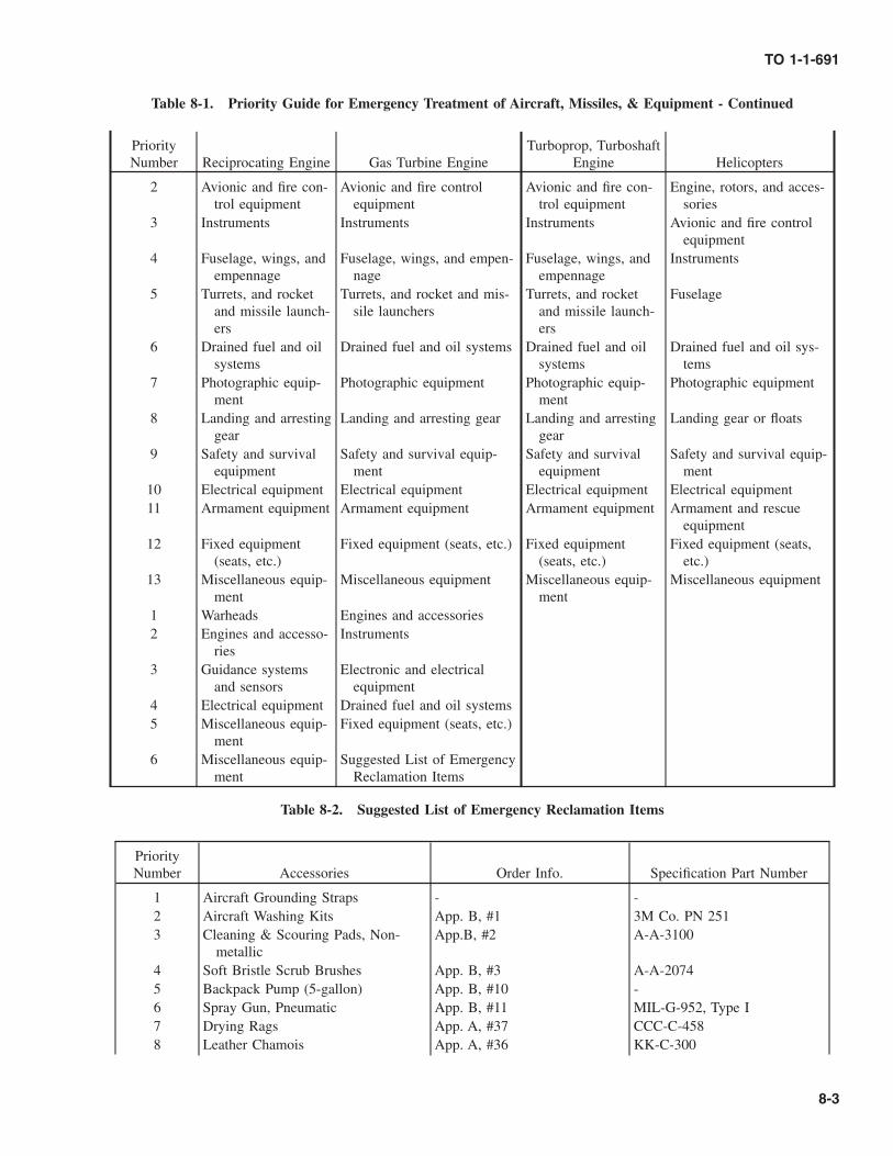
Table 8-1. Priority Guide for Emergency Treatment of Aircraft, Missiles, & Equipment - Continued
PriorityNumber Reciprocating Engine Gas Turbine Engine
Turboprop, TurboshaftEngine Helicopters
2 Avionic and fire con-trol equipment
Avionic and fire controlequipment
Avionic and fire con-trol equipment
Engine, rotors, and acces-sories
3 Instruments Instruments Instruments Avionic and fire controlequipment
4 Fuselage, wings, andempennage
Fuselage, wings, and empen-nage
Fuselage, wings, andempennage
Instruments
5 Turrets, and rocketand missile launch-ers
Turrets, and rocket and mis-sile launchers
Turrets, and rocketand missile launch-ers
Fuselage
6 Drained fuel and oilsystems
Drained fuel and oil systems Drained fuel and oilsystems
Drained fuel and oil sys-tems
7 Photographic equip-ment
Photographic equipment Photographic equip-ment
Photographic equipment
8 Landing and arrestinggear
Landing and arresting gear Landing and arrestinggear
Landing gear or floats
9 Safety and survivalequipment
Safety and survival equip-ment
Safety and survivalequipment
Safety and survival equip-ment
10 Electrical equipment Electrical equipment Electrical equipment Electrical equipment11 Armament equipment Armament equipment Armament equipment Armament and rescue
equipment12 Fixed equipment
(seats, etc.)Fixed equipment (seats, etc.) Fixed equipment
(seats, etc.)Fixed equipment (seats,
etc.)13 Miscellaneous equip-
mentMiscellaneous equipment Miscellaneous equip-
mentMiscellaneous equipment
1 Warheads Engines and accessories2 Engines and accesso-
riesInstruments
3 Guidance systemsand sensors
Electronic and electricalequipment
4 Electrical equipment Drained fuel and oil systems5 Miscellaneous equip-
mentFixed equipment (seats, etc.)
6 Miscellaneous equip-ment
Suggested List of EmergencyReclamation Items
Table 8-2. Suggested List of Emergency Reclamation Items
PriorityNumber Accessories Order Info. Specification Part Number
1 Aircraft Grounding Straps - -2 Aircraft Washing Kits App. B, #1 3M Co. PN 2513 Cleaning & Scouring Pads, Non-
metallicApp.B, #2 A-A-3100
4 Soft Bristle Scrub Brushes App. B, #3 A-A-20745 Backpack Pump (5-gallon) App. B, #10 -6 Spray Gun, Pneumatic App. B, #11 MIL-G-952, Type I7 Drying Rags App. A, #37 CCC-C-4588 Leather Chamois App. A, #36 KK-C-300
TO 1-1-691
8-3

Table 8-2. Suggested List of Emergency Reclamation Items - Continued
PriorityNumber Accessories Order Info. Specification Part Number
9 Cleaning Sponges App. B, #1 A-A-207310 Air Nozzle Gun App. B, #31 A-A-5554311 Air Hose Assembly App. B, #32 ZZ-H-500 / ZZ-H-52112 Vacuum Cleaner, Pneumatic (Wet/D
Vac)App. B, #17 & 18 A-A-54943
13 Utility Pails, Plastic App. B, #21 A-A-5924314 Large Trash Cans & Plastic Liners - -15 Water Nozzle App. B, #8 A-A-5046116 Water Hose App. B, #9 A-A-5927017 Goggles, Chemical Resistance App. B, #101 A-A-111018 Face Shield, Industrial App. B, #99 ANSI Z87.119 Rubber Apron App. B, #98 A-A-310420 Rubber Gloves, Industrial App. B, #82 MIL-G-1222321 Leather Palm Gloves (for handling
composite materials, medium sizedonly)
NSN: 8415-00-268-8350 A-A-50016
22 Barrier Material App. A, #69 MIL-PRF-131, Class 123 Aircraft Preservation Tape App. A, #73 AMS-T-22085, Type II24 Full Face Piece Respirator & Car-
tridgesApp. B, #64 & 67 -
25 Disposal Coveralls (Bunny Suit). App. B, #88 A-A-55196, Type II26 Heater Gun, Electric App. B, #16 A-A-59435
Consumable Materials27 Corrosion Preventive Compound,
Water Displacing (5-gal min. )App. A, #43 & 44 MIL-PRF-81309,Type II & III;
& MIL-L-87177, Type I &II, Grade B
28 Aircraft Cleaning Compound App. A, #19 & 20 MIL-PRF-87937, Type IV;MIL-PRF-85570, Type II
29 Engine Gas Path Cleaner App. A, #22 MIL-PRF-85704, Type II RTU30 Degreasing Solvent App. A, #97 A-A-59601, Type II; MIL-PRF-
680, Type II31 Isopropyl Alcohol (IPA) App. A, #101 TT-I-73532 Fire Extinguishing Agent (AFFF) App. A, #59 MIL-F-24385
b. Ensure that the aircraft, missile, or equipment is safe formaintenance. Electrically ground the aircraft, missile, orequipment by attaching the ground lead to the aircraft,missile or equipment at a point outside the area thatcould contain explosive vapors. Turn off all electricalpower and disarm all explosive and/or firing systems ona missile or an aircraft, including the ejection seat(s) onan aircraft .
c. Closely inspect the aircraft, missile, or equipment todetermine areas affected. Traces of foam type extin-guishing agents may not be evident; however, moist
residues often indicate previous foam application. Drypowders may be present in joints, faying surfaces, etc.,so a careful examination will be necessary to determineif they are present.
d. Wherever possible, remove components from affectedareas. Open, loosen, or remove covers, access plates,inspection doors, etc. Allow any accumulated salt wateror other liquids to drain off. If dry chemical fireextinguishing materials have been used, refer to Para-graph 8.5.3.
TO 1-1-691
8-4 Change 1

e. Remove gross amounts of contaminants by flushingwith fresh water and draining.
f. Remove components and process in accordance withParagraph 8.4.2 and Paragraph 8.4.3.
g. Clean the aircraft in accordance with Paragraph 8.4.4.
h. Inspect aircraft, missile, or equipment and determinewhether it can return to operational service followinglocal organizational level maintenance action or whetheradditional higher level maintenance will be necessary. Ifaircraft is locally repairable, repairs must be permanentrepairs before the aircraft, missile, or equipment isreleased for unrestricted operational service.
8.4.1 Removal of Contaminated Installed Equip-ment. After salt water immersion or entry or exposure toany corrosive agents, equipment must be cleaned promptlyand thoroughly. Follow the procedures in this chapter fordecontaminating specific areas and equipment. Refer to Table8-1 for assigning priority to equipment removal and treat-ment.
8.4.2 Disassembly/Removal of Components.
8.4.2.1 The mechanical cutting of fuel, hydraulic and oillines, and electrical leads, and other drastic operations nec-essary to expedite removal of parts are left to the discretion ofthe maintenance officer and/or maintenance superintendentdirecting the operations.
8.4.2.2 When aircraft are involved in water crashes, itshall be assumed that all components, including hollowstructural and mechanical members, are contaminated inter-nally. All components shall be disassembled and treated orforwarded to the appropriate ALC depot for disassembly andtreatment as required. Ensure that all contaminants have beenremoved and that all corroded surfaces have been effectivelytreated to inhibit further attack prior to returning the aircraftto operational service.
8.4.3 Clean. Equipment and components shall becleaned by the team, in accordance with Paragraph 8.5,Paragraph 8.6, and Paragraph 8.7, and then delivered to thedesignated shops for further inspection and maintenance.Equipment that cannot be removed shall be cleaned in placeand inspected.
NOTE
All equipment subject to emergency reclamationteam procedures must be certified operationallyready before returning to serviceable status. In-spect equipment for corrosion, cracks and heatdamage. Obtain the maximum available engi-neering assistance to evaluate the extent of dam-age. Particular attention shall be given to dissimi-lar metal joints. Avionic, electronic, and electricalequipment usually contain dissimilar metals.
8.4.4 Tagging. All parts and components removed fromthe aircraft, missile, or equipment shall be “green” tagged(DD Form 1577-3) for identification, description of theaccident/incident experienced, listing of the contaminants andchemical materials to which they were exposed, and toindicate the type of CPC applied. CPC’s shall be removedprior to reusing the equipment.
8.5 GENERAL CLEANING PROCEDURES.
Contaminated areas may be cleaned by several methods. Theprimary method is fresh water flushing. Alternate methodsmay be used when fresh water is not available. Use themethods in Paragraph 8.6, and Paragraph 8.7 for emergencytreatment of specific components. Do not use the followinggeneral methods when specific methods are available.
8.5.1 Primary Method.
Prolonged breathing of vapors from organic sol-vents or materials containing organic solvents isdangerous. Prolonged skin contact with manyorganic solvents or solvent containing materialscan have toxic effect on exposed skin areas.Observe precautions listed in previous chapters,referenced manuals, and MSDSs for cleaningcompounds, solvents, surface treatment chemi-cals, sealants, primers, and paints.
Do not expose plastic or rubber items; avionic,electronic, or electrical components; wiring; orother components susceptible to heat damage totemperatures in excess of 130° F (54° C) andany/all other areas to temperatures in excess of150° F (66° C) during emergency cleaningprocedures.
NOTE
Always use the mildest cleaning cycle availablethat will ensure proper decontamination. Eventhough fresh water/detergent wash should notsignificantly affect accident investigations, per-mission must be obtained from the senior mem-ber of the appointed accident investigation boardbefore performing this operation.
The primary method of removing salt water is as follows:
a. Immerse removed unit or component in clean, freshwater whenever possible.
TO 1-1-691
8-5

b. Flush all areas with clean fresh water and allow them todrain.
c. Dry the item or areas by vacuum cleaning excess waterand/or blotting with a cloth or paper towels, or blowingdry with compressed air at a pressure not greater than 10PSI. If visual evidence of salt remains, a second clean-ing should be accomplished as follows:
(1) Mix a solution of one part of MIL-PRF-87937, TypeIV, or MIL-PRF-85570, Type II aircraft cleaningcompound in nine parts water.
(2) Apply the solution to the affected areas and scrubwith bristle brushes, sponges or cloths.
(3) Flush thoroughly with clean fresh water and drainthoroughly.
(4) Dry the item or areas as before.
d. After flushing and drying, apply MIL-PRF-81309, TypeIII, or MIL-L-87177, Type I or II, Grade B waterdisplacing CPC/preservative on all avionic, electronic,or electrical components and connectors. Ensure that allareas and crevices are coated. Apply a liberal amount ofMIL-PRF-81309, Type II, or MIL-L-87177, Type I or II,Grade B water displacing CPC to all other areas thatcannot be properly drained or contain recesses which aredifficult to reach. Ensure that all surfaces are coated.
NOTE
MIL-PRF-81309, Type II water displacing CPCdeposits a thin, nonconductive film which mustbe removed for proper function of contact pointsand other electromechanical devices where noslipping or wiping action is involved, but MIL-PRF-81309, Type III, and MIL-L-87177, Type Ior II, Grade B need not be removed as they do notinterfere with proper function of these items.CPC is easily removed with A-A-59601, or MIL-PRF-680, Type II or III degreasing/dry cleaningsolvent. Removal will be accomplished duringsubsequent maintenance or functional test priorto issue for use.
8.5.2 Alternate Methods. Use only when fresh water isnot available or is available only in limited supply or whentime prevents immediate flushing with fresh water.
8.5.2.1 Method One (preferred). Spray, brush, or wipethe exterior of the affected areas and components with liberal
amounts of MIL-PRF-81309, Type II, or MIL-L-87177, TypeI or II, Grade B water displacing CPC/preservative.
8.5.2.2 Method Two (alternate).
a. Apply a solution of one part MIL-PRF-87937, Type IV,or MIL-PRF-85570, Type II aircraft cleaning compoundin nine parts water by spray, brush, or cloth.
b. Brush affected areas until contaminants and cleanerbecome intermixed or emulsified.
c. Wipe off thoroughly with a clean cloth, to remove bothcontaminants and cleaner.
d. Apply a liberal amount of MIL-PRF-81309, Type II, orMIL-L-87177, Type I or II, Grade B water displacingCPC to affected areas.
8.5.3 Removing O-D-1407 Potassium Bicarbonate(Purple K Powder/PKP or Other Dry Chemical FireExtinguishing Agents. Remove powder as follows:
a. Remove as much as possible by vacuuming.
b. Use a soft bristle brush and air pressure not greater than10 PSI to dislodge contaminants between close-fittingcomponents.
c. Vacuum clean again.
d. Remove the residual film of dry powder adhering to thesurface by wiping, brushing, or spraying with a solutionof one part of MIL-PRF-87937, Type IV, or MIL-PRF-85570, Type II aircraft cleaning compound in nine partsof water.
e. Rinse thoroughly with fresh water.
f. Dry with cloths or paper towels and/or blow dry withdry, oil free compressed air at a pressure not greater than10 PSI.
g. Apply a liberal amount of MIL-PRF-81309, Type II orMIL-L-87177, Type I or II, Grade B water displacingCPC to the affected area.
h. Enter a notation defining the affected areas and whereand how they were treated in the appropriate aircraft,missile, or equipment forms with a requirement for aspecial inspection as corrosion prone areas at a specifiedfuture time to determine if any corrosion has occurred.
TO 1-1-691
8-6 Change 1

8.5.4 Removing MIL-F-24385 Aqueous Film FormingFoam (AFFF) Fire Extinguishing Agent. To removeresidues of burned materials and fresh water solutions ofAFFF, use the following procedure:
NOTE
• AFFF and fresh water mixtures usually do notpresent a corrosion problem, but cleanup ofresidues of burned materials after a fire isrequired for corrosion prevention.
• Enter a notation defining areas and compo-nents that are exposed to residue from burnedmaterials and MIL-F-24385 AFFF fire extin-guishing agent in the appropriate aircraft,missile, or equipment forms with a require-ment for a special inspection as corrosionprone areas or components at a specifiedfuture time to determine if any corrosion hasoccurred.
a. Flush all affected areas with fresh, clean water whiledraining at the same time. Whenever possible, units orcomponents which have been removed, should be im-mersed in fresh water and then flushed thoroughly withfresh, clean water. Drain away the water.
b. Clean surfaces with a solution of one part MIL-PRF-87937, Type IV, or MIL-PRF-85570, Type II aircraftcleaning compound in nine parts of water. Scrub af-fected areas and rinse with clean, fresh water. Drainaway excess water.
c. Dry with cloths, paper towels, and/or dry, oil freecompressed air at a pressure not greater than 10 PSI.
d. Apply MIL-PRF-81309, Type III, or MIL-L-87177,Type I or II, Grade B water displacing CPC to allavionic components and electrical connectors. Apply aliberal amount of MIL-PRF-81309, Type II, or MIL-L-87177, Type I or II, Grade B water displacing CPC to allother areas that cannot be properly drained or containrecesses which are difficult to reach.
e. Enter information on affected areas and/or componentsin the appropriate aircraft, missile, or equipment formsper the instructions in the above NOTE.
f. Dismantle engine to piece part component level for allcomponents exposed to inlet flow path air.
g. Clean engine components exposed to AFFF per theappropriate depot level component cleaning procedureor clean per Paragraph 8.5.6.
8.5.5 Removal of Carbon Dioxide (CO2), HFC-125,or Halon Fire Extinguishing Agents. CO2, HFC-125(Pentafluoroethane), Halon 1211 (MIL-DTL-38741, Bromo-chlorodifluoromethane), and Halon 1301 (ASTM D5632,Bromotrifluoromethane) evaporate rapidly. Therefore, nocleanup is required unless moisture or a high temperature was
present at the area of application; but ventilation shouldalways be provided to remove the vapors. If moisture or hightemperature was present, use the following clean up proce-dures for Halon materials:
NOTE
Even though carbon dioxide or Halon fire extin-guishing agents leave no residues; smoke,smudges, or other grime from a fire should beremoved from affected items that are to beretained for future use.
a. After a fire has been extinguished, purge area andsurfaces with clean, dry air (dust and oil free, lowmoisture content, compressed air).
b. Clean surfaces with a solution of one part MIL-PRF-87937, Type IV, or MIL-PRF-85570, Type II aircraftcleaning compound in nine parts of water. Scrub af-fected areas and rinse with clean, fresh water. Drainaway excess water.
c. Dry with cloths, paper towels, and/or dry, oil freecompressed air at a pressure not greater than 10 PSI.
d. Apply MIL-PRF-81309, Type III, or MIL-L-87177,Type I or II, Grade B water displacing CPC to allavionic components and electrical connectors. Apply aliberal amount of MIL-PRF-81309, Type II, or MIL-L-87177, Type I or II, Grade B water displacing CPC to allother areas that cannot be properly drained or containrecesses which are difficult to reach.
e. Enter a notation defining the affected areas, and whereand how they were treated in the appropriate aircraft,missile, or equipment forms with a requirement for aspecial inspection as corrosion prone areas at a specifiedfuture time to determine if any corrosion has occurred.
8.5.6 Removal of Protein Type Foam and Soda-AcidFire Extinguishing Agents. The residues left from the useof these materials can be very corrosive to aircraft, missiles,and equipment. Remove these residues as follows:
a. Thoroughly flush the affected area with fresh water.Ensure that the rinse water is completely flushed fromthe aircraft, missile, or equipment.
b. Clean surfaces with a solution of one part of MIL-PRF-87937, Type IV, or MIL-PRF-85570, Type II aircraftcleaning compound in nine parts of water. Scrub af-fected areas and rinse with clean, fresh water. Drainaway excess water.
c. Dry with cloths, paper towels, and/or dry, oil freecompressed air at a pressure not greater than 10 PSI.
d. Apply MIL-PRF-81309, Type III, or MIL-L-87177,Type I or II, Grade B water displacing CPC to allavionic components and electrical connectors. Apply aliberal amount of MIL-PRF-81309, Type II, or MIL-L-
TO 1-1-691
Change 1 8-7

87177, Type I or II, Grade B water displacing CPC to allother areas that cannot be properly drained or containrecesses which are difficult to reach.
e. Enter a notation defining the affected areas, and whereand how they were treated in the appropriate aircraft,missile, or equipment forms with a requirement for aspecial inspection as corrosion prone areas at a specifiedfuture time to determine if any corrosion has occurred.
8.5.7 Treatment After Landing on a Foamed Run-way. Materials used to foam runways are corrosive toaircraft. As soon as possible after a landing on a foamedrunway, exterior areas, wheel wells, any interior areas ex-posed, and engines shall be cleaned. Clean the exterior andwheel wells, interior areas, and engines in accordance withSection I of Chapter 3.
8.5.8 Treatment After Exposure to Volcanic Ash. Theprimary concern in removing volcanic ash is the extremeabrasiveness of the ash. It is not a significantly corrosivematerial. Aircraft, missiles, and equipment which have beenexposed to volcanic ash should be cleaned using the follow-ing procedures before the next aircraft, missile, or equipmentoperation:
a. All static ports, fuel vents, engine inlets, air condition-ing inlets, etc., should be vacuumed to remove as muchash as possible and then suitably covered to precludeadditional ash entry. Special emphasis should be placedon ducting supplying cooling air to avionics, electronics,and electrical equipment.
b. After covering all openings where ash may enter, theexterior of the airframe, missile or equipment shouldhave ash removed initially using a vacuum, low pres-sure, compressed air (not to exceed 10 PSI), or bylightly dusting with clean rags. Avoid rubbing since thismay damage painted and bare metal surfaces due to theabrasiveness of the ash.
c. Wash entire aircraft, missile, or piece of equipmentusing a mild MIL-PRF-87937, Type IV, or MIL-PRF-85570, Type II alkaline cleaner and water solution (1part cleaner to 9 parts water) using procedures inSection I of Chapter 3 and rinse thoroughly with lowpressure water. Ensure that critical parts, such as flapscrews, tracks, and exposed hydraulic actuators areadequately cleaned. Again, caution should be takenwhen washing to avoid vigorous rubbing/scrubbing,since ash is even more abrasive when combined withwater to form a slurry.
d. Check windshield wiper blades to ensure that all con-taminants are removed prior to operation.
e. If ash penetration is evident in the aircraft interior (thecockpit, cargo area, avionics compartments, and otheraccessible interior areas) or interior areas and compart-ments of missiles and equipment; they should be thor-oughly vacuumed.
f. Check lower aircraft, missile, and/or equipment struc-tures for volcanic matter and water entrapment.
g. Clear all drains and air dry structures as much aspossible.
h. Uncover all openings which were covered during step a.
i. After washing, the aircraft, missile, or piece of equip-ment must be lubricated in accordance with applicablesystem specific maintenance manuals.
8.6 SPECIFIC INTERNAL AREAS.
The cockpit, ejection seats, avionic and electrical equipment,identification and modification plates, and photographicequipment require specific emergency cleaning procedures.
8.6.1 Aircraft Cockpit Area. Emergency cleaning pro-cedures for the aircraft cockpit are as follows:
a. If the interior is undrainable, drill out a few fasteners atlow points. If still undrainable, drill holes at low pointsas approved and directed by the aircraft SPD.
b. Remove avionics equipment, relay boxes, circuit break-ers and switches, and clean as specified in TO 1-1-689.
c. Clean ejection seats (refer to Paragraph 8.6.2).
d. Turn equipment over to the activity that has the author-ity and capability to disassemble, clean, and repair theequipment.
e. Dry equipment that has been cleaned as much aspossible with dry, oil free compressed air at a pressureless than 10 PSI, drying machines, electric fans, or handfans in a hot room of 150° F (66° C) maximum or in awell ventilated room where the humidity is low.
f. Apply MIL-PRF-81309, Type II, or MIL-L-87177, TypeI or II, Grade B water displacing CPC by spraying orbrushing onto all areas that cannot be properly drainedor contain recesses which are difficult to reach.
8.6.2 Aircraft Ejection Seats.
Disarm ejection seat mechanism before cleaning.Ensure that only authorized personnel disarmseats and perform cleaning operations.
The following emergency cleaning procedure shall be usedfor cleaning aircraft ejection seats:
a. Remove parachutes, drogue parachutes (where appli-cable), and seat pans. Return them to the local survivalequipment work center for cleaning and/or replacement.
TO 1-1-691
8-8 Change 1

b. Remove ejection seat in accordance with the applicablesystem specific maintenance manual.
c. Rinse seat thoroughly with fresh water. Continue rinsingwhile directing water into crevices and close fitting partsuntil contaminants are removed.
d. Wipe down cartridge activated devices, rockets, andinertia reels with fresh water. Disarm and remove fromseats. Cap all gas lines and ports.
e. Remove as much water as possible from equipment withvacuum or low pressure, clean, dry, oil free compressedair.
f. Dry off any remaining water with a clean cloth or papertowels.
g. Apply MIL-PRF-81309, Type II, or MIL-L-87177, TypeI or II, Grade B water displacing CPC by either spray orbrush application to critical metal surfaces and recessareas which may not be completely dry. Water displac-ing CPC protects equipment during necessary inspec-tions and/or inquiry and during transfer to the localsurvival equipment work center.
h. Wash all survival gear and pilot safety equipment withfresh water and dry thoroughly. Refer to applicablesystem specific maintenance requirements for detailedpreservation procedures. Lubricate and apply CPC’s inaccordance with the applicable system specific mainte-nance cards and Sections II and III of Chapter 3 in thismanual.
i. If necessary, send the entire ejection seat to the appro-priate ALC Depot for overhaul/repair.
j. Aircraft mounted escape system components (mechani-cally activated CADS) shall be wiped and dried with aclean cloth and fresh water. If internal contamination issuspected, remove and replace. Forward removed com-ponents to the appropriate ALC Depot for furtherdisassembly, inspection, and repair.
8.6.3 Avionic, Electronic and Electrical Equipment.
Ensure that all electrical power is disconnectedand all systems in the aircraft, missile, or equip-ment are deactivated before starting the cleaningoperation on avionics, electronic, or electricalequipment to prevent electrical shock.
Effective cleaning ensures that salt water, fire fighting chemi-cals, and other corrosive agents are completely removed toprevent corrosion damage. Refer to TO 1-1-689 for specificcleaning procedures.
8.6.4 Photographic Equipment. Use the following pro-cedure for cleaning photographic equipment:
a. Immediately rinse with fresh water, drain and rinseagain.
b. Apply MIL-PRF-81309, Type III, or MIL-L-87177,Type I, Grade B water displacing CPC by spraying.
c. Return to the appropriate photographic equipment tech-nician for prompt servicing.
8.6.5 Graphite or Carbon Fiber/Epoxy, Boron Fiber/Epoxy, and Tungsten Fiber/Epoxy Composite Materi-als.
• The inhalation of graphite, boron, or tungstencomposite fibers resulting from aircraft, mis-sile, or equipment fires and/or material dam-age may be harmful to personnel. Wear acartridge type respirator and goggles whenexposed to these materials, and, in addition,wear close weave cotton gloves when han-dling these materials. Request the assistanceof the local bioenvironmental engineer andsafety officer to provide specific informationregarding hazards to personnel during cleanupoperations involving these materials and therequired PPE.
• Do not put power to or start up any aircraft,missile, piece of equipment or other avionic/electronic/electrical equipment which havebeen exposed to debris until decontaminationby vacuuming and/or washing is completed.Failure to observe these procedures may resultin electrical short circuits and fires.
Aircraft, missile, or equipment constructed utiliz-ing graphite, boron, or tungsten fiber compositematerials in contact with metal structures orsubstructures create a high potential for establish-ing galvanic corrosion cells. This can result incorrosion of the metal components if the structureis exposed to an electrolyte medium, such as saltwater.
The graphite, boron, and/or tungsten fibers of compositematerials may be released into the atmosphere if their epoxybinder burns; this occurs at temperatures in excess of 600 F(316 C). In addition, fibers may be released during anexplosion or a high impact crash. Since graphite, boron, andtungsten are very conductive, these fibers can damage unpro-tected avionic, electronic, and electrical equipment withinseveral miles of the incident site by settling on and shortingout electrical contacts. The procedures for treating damagedcomposite materials are listed below. Refer to TO 1-1-690 foradditional information.
TO 1-1-691
Change 1 8-9

8.6.5.1 Cleanup. When damaged aircraft, missiles, orequipment have graphite, boron, or tungsten fiber compositesurfaces which are broken or burned, follow these proce-dures:
8.6.5.1.1 If ventilation inlets are exposed to debris, takeimmediate action to ensure that the filtration system isproperly operating. If the system is not operating properly,shut down the system and provide temporary filtration atoutlets leading to compartments with electrical, avionic, andelectronic equipment.
8.6.5.1.2 Warn the flight crew of adjacent in-flight aircraftand maintenance control for flight line operations that thesmoke may contain hazardous electrical contaminants.
8.6.5.1.3 Spray MIL-PRF-81309, Type II, or MIL-L-87177, Type I, Grade B CPC on damaged composite surfaces.This will prevent the spread of graphite, boron, or tungstenfiber contamination by causing the fibers to stick togetherand/or to the damaged surface. Cover damaged surfaces withplastic sheet and tape it securely in place.
8.6.5.1.4 Aircraft, missiles, facilities, clothing and equip-ment that have been exposed to debris from the aircraft,missile, or equipment fire must be vacuumed and/or washeddown prior to reuse or movement into a hanger.
8.6.5.1.5 Decontamination of the immediate area of theaircraft, missile, or equipment wreckage may require vacu-uming, washing, and bagging, of composite material frag-ments. Use a sealed industrial vacuum and store the collecteddebris in sealed plastic bags for the accident investigationboard. Dispose of the debris in accordance with applicableregulations when so directed by the investigation team.
8.6.5.1.6 If wrapping and secure taping of the aircraft,missile, or equipment wreckage is not possible, transportingthe wreckage must be planned to bypass heavily populatedand industrial areas. Aircraft, missiles, or equipment parkedor located along the planned route must have their canopiesand access doors closed and their engine inlet and exhaustopenings, air intakes and outlets, and all other vents and portscovered. In addition, the doors and windows of surroundingbuildings should be closed to minimize the probability ofhaving wind-blown fibers enter areas containing electricaland electronic equipment.
8.7 SPECIFIC EXTERNAL AREAS OF AIRCRAFT.
The following external aircraft areas require emergencycleaning after exposure to fire and fire fighting agents.
8.7.1 Airframes. Use the following procedure for clean-ing airframes:
a. Flush all areas with fresh, clean water while draining atthe same time. Whenever possible, units or componentsthat have been removed from the aircraft should beimmersed in fresh water and then flushed thoroughlywith clean, fresh water. Drain away the water and dry
the areas with cloths, paper towels, or dry, oil freecompressed air at a pressure of less than 10 PSI.
b. Clean with a solution of one part of MIL-PRF-87937,Type IV, or MIL-PRF-85570, Type II aircraft cleaner innine parts of water. Scrub affected areas with thesolution. Flush thoroughly with fresh water and drainaway the excess water. Dry with cloths, paper towels, ordry, oil free compressed air at a pressure of less than 10PSI.
c. Apply a liberal amount of MIL-PRF-81309, Type II, orMIL-L-87177, Type I or II, Grade B water displacingCPC by spraying or brushing to all other areas thatcannot be properly drained or contain recesses which aredifficult to reach, to aid in the removal of water.
d. If the aircraft fuselage, empennage, or wings are in arepairable condition, drain holes may be provided fordraining water by drilling out rivets at the lowest points.All repairable parts shall be collected and returned withthe aircraft when shipment is made.
8.7.2 Antennas. Remove antennas per instructions inthe system specific aircraft and/or specific equipment main-tenance manual. Treat in accordance with TO 1-1-689.Accomplish any in place cleaning as follows:
a. Check antenna insulators for damage or cracks.
b. Brush or spray a solution of one part MIL-PRF-87937,Type IV, or MIL-PRF-85570, Type II aircraft cleaningcompound in nine parts water onto the antenna and theaffected adjacent area, and scrub the area with a small,soft brush or wiping cloth dipped in the above cleaningsolution.
c. Rinse with clean, fresh water.
d. Dry the area with a clean, dry cloth.
8.7.3 Reciprocating Engines.
a. Determine the extent of contamination.
b. Drain all fluids. Partial disassembly is authorized toaccomplish thorough draining. Ensure that pressuresystems and cylinders are drained.
c. Thoroughly flush all surfaces and passages with freshwater.
d. Apply A-A-59601 or MIL-PRF-680, Type II or III drycleaning/degreasing solvent to the affected areas with abrush, cloth, or non-atomizing spray, and scrub the areawith a brush or cloth.
e. Flush all accessible interior surfaces and all passageswith either a solution of one part MIL-C-85704, Type IIturbine engine gas path cleaning compound in four partsfresh water or use the straight undiluted form of MIL-
TO 1-1-691
8-10 Change 1

C-85704, Type II ready to use (RTU) cleaner. Both theType II and Type II RTU are aqueous cleaners withoutany hydrocarbon solvents.
f. Thoroughly rinse all areas with fresh water.
g. Allow to thoroughly drain. Dry using paper towels,cloths, or dry, oil free compressed air at a pressure ofless than 10 PSI.
h. Apply a liberal amount of MIL-PRF-81309, Type II, orMIL-L-87177, Type I or II, Grade B water displacingCPC to all surfaces. This may be accomplished by fillingand draining (preferred), flushing, or spraying. Rotatethe propeller shaft to coat cylinder walls. Drain excessCPC.
i. Reassemble engine finger tight.
j. Lubricate any pressure lubrication points to displace allcontaminated lubricant.
k. For shipping, place engine in an approved dehydratedmetal container, using twice the normal amount ofdesiccant. Notify the engine SPM to arrange for specialhandling as required.
8.7.4 Turbine Engines. Engines which are contami-nated with small amounts of sea water entering the intakeshall be cleaned using MIL-PRF-85704 engine gas pathcleaner in accordance with Table 3-2 and the engine systemspecific technical/overhaul manuals. Decontaminate enginesthat have been completely submerged in fresh water or seawater as follows:
a. Drain all fluids. Partial disassembly is authorized toaccomplish thorough draining.
b. Thoroughly flush all surfaces and passages with freshwater.
c. Flush all accessible interior surfaces and all passageswith either a solution of one part MIL-PRF-85704, TypeII turbine engine gas path cleaning compound in fourparts fresh water or use the straight undiluted form ofMIL-C-85704, Type II RTU cleaner. Both Type II andType II RTU are aqueous cleaners without any hydro-carbon solvents.
d. Thoroughly rinse all areas with fresh water.
e. Drain thoroughly.
f. Apply a liberal amount of MIL-PRF-81309, Type II, orMIL-L-87177, Type I or II, Grade B water displacingCPC to all surfaces. This may be accomplished by fillingand draining (preferred), flushing, or spraying. Drainexcess CPC. Repeat this procedure until all traces ofwater have been removed.
g. Lubricate any pressure lubrication points to completelydisplace all contaminated lubricant.
h. For shipping, install in an approved dehydrated metalcontainer, using twice the normal amount of desiccant.Notify the engine SPM to arrange for special handlingas required.
8.7.5 Treatment for Engines Which Have IngestedFire Extinguishing Powder (Purple K/PKP, AqueousFilm Forming Foam (AFFF), and/or Sodium Bicarbon-ate).
a. With the ignition off/disconnected, vacuum up as muchof the loose powder/foam as possible followed bycranking the engine and rinsing it thoroughly withwater.
b. Wash the engine with MIL-PRF-85704 gas path cleanerper instructions in Table 3-2 and Paragraph 8.5.4 and8.5.7.
c. Flush all accessible interior surfaces and all passageswith either a solution of one part MIL-PRF-85704, TypeII turbine engine gas path cleaning compound in fourparts fresh water or use MIL-PRF-85701, Type II, RTUcleaner undiluted. Both Type II and Type II RTU areaqueous cleaners without any hydrocarbon solvents.
d. Based on the high-temp metals and unique coatings/finishing materials used in the manufacturing of theseend items, cleaning of engines exposed to any fire or fireextinguishing products, requires consulting the weaponsystem specific technical order, depot overhaul manual/procedures, original equipment manufacturer (OEM)manual, and the appropriate engine engineering author-ity for potential additional actions required such asdismantling of the engine.
e. Drain engine lubricant/oil and refill/service.
f. At the next inspection, recheck previously contaminatedareas and repeat the above procedure, if necessary.
8.7.6 Helicopter Transmission, Rotor Head, and Ro-tor Hub. Helicopter transmission, rotor head, and rotor hubcases are often constructed of magnesium. Magnesium partsexposed to salt water or fire fighting chemicals requireimmediate and thorough decontamination and preservation.
8.7.6.1 External Surface Contamination. Treat heli-copter transmissions, rotor heads, and rotor hubs with exter-nal surface contamination as follows:
a. Rinse with fresh water.
b. Wash with a solution of one part MIL-PRF-87937, TypeIV, or MIL-PRF-85570, Type II aircraft cleaning com-pound in nine parts fresh water or use MIL-C-43616,Class 1A aerosol type solvent emulsion aircraft cleanerper instructions in Section I of Chapter 3, and rinsethoroughly.
TO 1-1-691
Change 1 8-11

c. Apply a liberal amount of MIL-PRF-81309, Type II, orMIL-L-87177, Type I, or II, Grade B, water displacingCPC to all affected areas by spraying or brushing.
d. Lubricate all pressure lubrication points to displace allcontaminated lubricant.
8.7.6.2 Internal Surface Contamination. If internalsurface contamination of helicopter transmissions, rotorheads, and gearboxes is suspected, immediately contact theappropriate helicopter SPD for assistance with decontamina-tion procedures. Treat helicopter transmissions, rotor heads,rotor hubs, and gear boxes having internal contamination asfollows:
a. Drain all fluids. Partial disassembly is authorized toaccomplish thorough draining. Ensure that pressuresystems are drained.
b. Thoroughly flush all surfaces and passages with freshwater.
c. Flush all surfaces and passages with a solution of onepart MIL-PRF-87937, Type IV, or MIL-PRF-85570,Type II aircraft cleaning compound in nine parts freshwater per instructions in Section I of Chapter 3.
d. Thoroughly rinse all areas with fresh water.
e. Allow to drain thoroughly.
f. Apply a liberal amount of MIL-PRF-81309, Type I, orMIL-L-87177, Type I or II, Grade B water displacingCPC to all surfaces. This may be accomplished by fillingand draining (preferred), flushing, or spraying. With thehousing full of preservative, rotate the main shaftapproximately five revolutions. After the preservativehas remained in the housing for four hours, drain, andreplace plugs.
g. Service the transmission, rotor head, rotor hub, and/orgear box in accordance with the applicable systemspecific maintenance manual if going back in service orleave as preserved if the unit will be shipped out.
h. Lubricate all pressure lubrication points to displace allcontaminated lubricant.
8.7.7 Helicopter Main and Tail Rotor Blades. Heli-copter blades that have been exposed to an excessive amountof salt water or to liquid fire fighting chemicals shall betreated as follows:
NOTE
Some rotor blades have areas commonly knownas pockets or blade boxes with very small drainholes. The drain holes may require enlargement,if blades were salt water immersed, to facilitatedecontamination of the blade spar. Enlargingdrain holes destroys the affected pockets or bladeboxes and requires Depot Level repair before theblade can be reused. Enlargement of pocketaccess openings requires authorization from theappropriate helicopter SPD and blade SPM foreach blade involved. Where possible, flush pock-ets with MIL-PRF-81309, Type II, or MIL-L-87177, Type II, Grade B water displacing CPC.Preserve and package the blade properly beforesending it to the appropriate ALC Depot forengineering evaluation and necessary repair.
a. Thoroughly flush all contaminated surfaces with freshwater. Pay particular attention to recesses that tend totrap debris such as mud, dirt, or salt deposits.
b. Wash with a solution of one part MIL-PRF-87937, TypeIV, or MIL-PRF-85570, Type II aircraft cleaning com-pound in nine parts fresh water per instructions inSection I of Chapter 3.
c. Rinse thoroughly with fresh water.
d. Dry with a cloth, paper towels or dry, oil free com-pressed air at a pressure of less than 10 PSI.
8.7.8 Armament. The following instructions are forinitial treatment of armament equipment that has undergonesalt water immersion or been subjected to fire extinguishingchemicals.
8.7.8.1 Safety Precautions. Before performing anycleaning chores, make certain that preliminary safety precau-tions are followed:
a. Ensure that the aircraft, missile or piece of equipment issafe for maintenance.
b. Disconnect all electrical power and ensure that allarmament switches are in the OFF or SAFE positions.
TO 1-1-691
8-12 Change 1

NOTE
For removal of armament equipment, refer toapplicable system specific maintenance/technicalmanual for the respective aircraft, missile, orpiece of equipment.
c. Remove all ordnance from the aircraft or piece ofequipment, and all warheads from the missile andproperly dispose of contaminated ammunition and war-heads as required.
8.7.8.2 Cleaning Procedure. After complying with thesafety precautions, clean per the following procedure:
a. Rinse equipment with fresh water.
b. Disassemble as required and wipe away excess greasewith clean cloth dampened with A-A-59601 or MIL-PRF-680, Type II or III dry cleaning/degreasing sol-vents.
c. Immerse and agitate parts in a solution of one partMIL-PRF-87937, Type IV, or MIL-PRF-85570, Type IIaircraft cleaning compound in nine parts of fresh water.
d. Rinse parts with fresh water to ensure complete removalof contaminants.
e. Wipe away excess water with clean, dry cloth.
f. Blow dry the cleaned equipment/parts as thoroughly aspossible with clean, dry, oil free compressed air at apressure of less than 10 PSI.
g. Inspect the equipment to determine whether it should bereturned to service or forwarded to the appropriate ALCDepot for overhaul or repair.
h. Apply a liberal amount of MIL-PRF-81309, Type II, orMIL-L-87177, Type I or II, Grade B water displacingCPC by either spray, brush, dip, or fill and drainapplication.
i. If shipment to the prime ALC Depot for maintenance isrequired, wrap the equipment in MIL-PRF-131, Class 1barrier material, package it per the applicable instruc-tions, and forward it to the depot as directed.
8.7.9 Aircraft Fuel Systems. For emergency treatmentof aircraft fuel systems contaminated with water throughother than a water crash or fire damage, refer to TO 1-1-3.
TO 1-1-691
Change 1 8-13/(8-14 blank)


CHAPTER 9SOUTHWEST ASIA ENVIRONMENTS
9.1 INTRODUCTION.
The Southwest Asia (SWA) Area of Responsibility (AOR)consists of varied regions from Afghanistan to South Africa.The conditions range from seasonal high winds and highhumidity to arid areas and low winds. In many locations,there are negatively charged ions (called anions) in soils thatwhen combined with aggressive sand storms, can spreadthroughout SWA (refer to Figure 9-1). The extent that sandand dust can penetrate equipment is dependent on manyvariables such as wind speed and direction, size of the dustparticles, protective shelter availability at the site, and equip-ment problems such as bad seals, gaskets and bent doors.Although sandstorms are usually seasonal, during the periodsof relative calm there can be a significant amount of airborndust seen as a general haze in the atmosphere (refer to Figure9-2).
9.1.1 Climatic Conditions. SWA contains varied cli-matic and environmental conditions. Temperatures canchange drastically from day to night. A desert environment islargely typical of SWA with the exception of coastal areas andareas with bodies of water close by; such as rivers, streams,and lakes. In certain areas of SWA, where there is low relativehumidity and rainfall, the dry air tends to decrease thecorrosion initiation and propagation action. In contrast, flightsover bodies of water, and operations near coastal areas withhigher humidity and recurring fog, provide moisture toextract soluble anions. These environments assist in thedevelopment of electrolytes for corrosion initiation. Thepotential for corrosion increases when moisture in the form ofhigh humidity (greater than 70%), rainfall, dew, fog, etc,combine with fine dust and sand containing corrosive anionssuch as chlorides, sulfates, nitrates and fluorides. During thedaylight hours, the equipment stored outdoors will normally
heat-up causing expansion of panels allowing hot moist air tomigrate into enclosed areas or under non-breathable fabriccovers. When the equipment cools, moisture condenses andcombines with dust particles and sand settling on metalsurfaces which increases the potential for corrosion. Thesoluble materials in the sand form a crust as they dry, makingremoval difficult.
Figure 9-1. Soil Makeup in the SWA Area
TO 1-1-691
Change 1 9-1

9.1.2 Aircraft Wash. Aircraft shall be washed in accor-dance with Table 3-1. If the water quality does not meetcriteria established in Paragraph 3.1.1f (1-9), the unit mustrequest a waiver in accordance with the NOTE in Paragraph3.2.3.1.
9.1.3 Aircraft Clear Water Rinse (CWR). CWR re-quirements in Paragraph 3.2.3 are not applicable to SWAlocations. If units need to remove dust and sand for opera-tional or specific maintenance reasons, dry cleaning processessuch as vacuum, brush, compressed air, etc, should be used tothe greatest extent possible. In rare cases where rinse opera-tions must be performed to remove accumulated dust andsand, water must meet the quality specified in Paragraph2.1.1f (1-9). After these limited rinse operations have beencompleted, accumulated water must be removed to minimizeeffects of chlorides found in many of the dusts and sands ofthe SWA environment.
9.1.4 Effects of Desert Environment. Soils in many ofthe SWA operating locations will cause or accelerate existingcorrosion if left in contact with metal surfaces in highhumidity conditions or in the presence of other moisture.However, if some type of moisture is not present, these soils,although high in potentially corrosive salts, do not supportcorrosion cell initiation or propagation. In all cases, the soilsshould be considered suspect and be regularly removed whilein-country or as soon as practical after the equipment returnsto home station.
NOTE
Recommend specific System Program Director(SPD)/System Program Offices (SPO) in con-junction with affected MAJCOM CorrosionFunctional Managers to develop a detailed check-list for each weapon system. Standardized check-lists for each phase of a deployment for aircraftand associated equipment will greatly improvethe overall condition when operating in SWAenvironments and increase equipment survivabil-ity and serviceability. Some general requirementsin the absence of weapons systems guidance areincluded in Paragraph 9.3 and Paragraph 9.4.This list may not be inclusive of all tasks.
9.2 PRE-DEPLOYMENT RECOMMENDATIONS.
a. Inspect entire aircraft exterior for missing and chippedprimer and/or paint. Correct all discrepancies prior todeployment.
b. Inspect and replace any worn, torn or cracked seals andgaskets that will allow sand and dust intrusion.
c. Accomplish a complete wash prior to deployment.
d. Remove all standing water.
e. Inspect all drain holes and unplug if needed.
f. Minimize aircraft lubrication by removing all excessgreases to limit sand and dust entrapment.
9.3 RECOMMENDED ACTIONS WHILE DEPLOYED.
Soils in operating locations in SWA should be consideredsuspect and be regularly removed. A constant regimen ofvacuuming, brushing, etc to remove dust and sand accumu-lation is necessary to reduce potential corrosion problems.Limit the use of compressed air to areas that will not causethe sand and dust to migrate and settle on other areas andcomponents.
9.3.1 High Efficiency Particulate Air (HEPA) Filtra-tion. HEPA filtration vacuum cleaners should be used togreatest extent because SWA sand and dust particulates arecommonly 10 microns or smaller. Numerous manufacturersproduce commercial off-the-shelf vacuum systems that aresuitable for SWA sand and dust removal.
a. Pneumatic wheeled units. Air volume consumption is30-60 CFM. Used for cargo decks or large surfaceswhere space is available.
Figure 9-2. Global Dust Producing Regions
TO 1-1-691
9-2 Change 1

b. Pneumatic Backpack. Air volume consumption is 70CFM. Portable for difficult to access areas in flightdecks, latrines, medium sized wheel wells. It can beremoved from the backpack frame for hand-held use.
NOTE
The units above require large volumes of air andare used in situations where electricity is unavail-able or restricted for use.
c. Electric models in floor and backpack are available in110-460 Volts @ 60 Hertz.
d. Battery pack portable units, requires 12-18 Volt batterypacks. Used for extremely small/confined areas such ascockpits, avionics bays, main and nose landing gear offighter aircraft.
9.3.2 Areas to be Checked and Cleaned. Listedbelow are some of the areas that should be checked andcleaned.
a. Wheel Wells.
b. Exposed control cables, pulleys, and gears.
c. Flap wells, control surface wells, personnel restraintattach points.
d. Access doors and service compartments.
e. Crew entry and exit doors. Latch release doors andpanels.
f. Cockpit interior and flight decks.
g. Inside engine pylons and lower sections of nacelles.
h. Cargo ramps and recessed areas of cargo decks.
i. Avionic instruments, electrical panels and bays (refer toFigure 9-3), especially those with cooling vents andintake fans.
j. All areas susceptible to standing water. Keep all drainholes open by inserting a probe, such as a pipe cleanerbefore and after vacuuming.
NOTE
If sand is hard and crusted, gently break up withnon-metallic tool and remove with vacuum.
9.4 POST DEPLOYMENT.
a. Inspect all areas listed in Paragraph 9.3.2.
b. Remove as much entrapped sand and dust as practicalwith dry cleaning processes such as vacuum, brush,compressed air, etc.
c. Perform thorough aircraft wash (NLT 30 days) afterarrival to home station.
d. Remove all standing water.
e. Inspect exterior surfaces for areas of missing primer andpaint erosion. Correct all deficiencies.
9.5 CORROSION PREVENTIVE COMPOUNDS(CPC’S).
Corrosion preventive compounds are used to protect aircraft,missile, and equipment parts and components by preventingcorrosive materials from contacting and corroding bare metalsurfaces. Section IV, Chapter 3 of this TO lists CPC types andapplications. Recommend applying these products ahead ofscheduled deployment if known.
9.5.1 Recommended CPC’s. Since general purpose,soft, oily CPC such as MIL-PRF-81309, Type II and MIL-PRF-16173, Grades 1, 2 and 4, have a tendency to attract andhold sand and dust particles, they should not be used in SWAenvironments unless mandated in weapons system specificTO’s. In all cases, CPCs should be used sparingly and anyexcess removed at the time of application. MIL-L-87177 andMIL-PRF-81309, Type III deposit ultra-thin films that are lesssusceptible to sand and dust accumulation, so they shouldcontinue to be used in the all applications addressed in thisTO, TO 1-1-689 and all weapons specific TO’s. MIL-DTL-85054 (AMLGUARD) produces a dry, thin film that also doesnot attract and hold dust and sand particles. Apply this CPCto aircraft or equipment surfaces for temporary protection ifconventional primers and topcoats are not available or otherlimitations prevent their use. This CPC is not suitable for useon the interior of electrical or electronic equipment orconnectors.
Figure 9-3. Open Circuit Board
TO 1-1-691
Change 1 9-3/(9-4 blank)


APPENDIX ACONSUMABLE MATERIALS
A.1 INTRODUCTION.
Table A-2 provides consumable materials used for aircraft,missile, and equipment cleaning and corrosion preventionand control. Nomenclatures, specifications/part numbers, na-tional stock numbers, units of issue, and intended use ofmaterials are provided. Items are located by function in thefollowing groupings:
• Abrasives
• Conversion coating materials
• Cleaning compounds
• Cleaning pads/cloths
• Corrosion preventive compounds
• Lubricants
• Neutralizing agents
• Protective materials
• Sealants and sealant accessories
• Solvents
A.1.1 Shelf Life. Shelf life and its extension data (givenin months) for materials that have a shelf life are provided inAFMAN 23-110 and the Shelf-Life Extension Data (SLED)Program managed by WR-ALC/MADL at Robins AFB, GA
(HQ USAF/SLED; DSN 468-4005 or COM (478) 926-4005;FAX same prefixes and -1276; [email protected]). TO42C-1-12 covers qual-ity control procedures for chemical materials.
A.1.2 Consumable Materials Containers. Consum-able materials of a particular specification are provided invarious sized containers. If the particular sized containerrequired is not available or listed, ask supply department toprovide the next size container under the same specification.
A.1.3 Local Purchase. When local purchase is speci-fied, include all procurement information, source of supplyand GSA contract number available.
A.1.4 Local Environmental Laws and Regulations.Prior to the procurement/use of any of specified products forcleaning, corrosion prevention, touch-up painting, etc., deter-mine and comply with all local environmental requirements,i.e., laws and regulations.
A.1.5 Units of Issue Codes. The units of issue codes inthe unit issue column and their meaning are as follows inTable A-1:
Table A-1. Units of Issue Codes
CODE UNIT CODE UNIT CODE UNIT
BG Bag EA Each PG PackageBO Bolt FT Foot PR PairBT Bottle GL Gallon PT PintBX Box GR Gross QT QuartCA Cartridge JR Jar RO RollCB Carboy KG Kilogram SE SetCC Cubic Cent. KT Kit SH SheetCN Can L Liter TU TubeCO Container LB Pound YD YardCS Case LG LengthDR Drum MX ThousandDZ Dozen OZ Ounce
TO 1-1-691
A-1

Tabl
eA
-2.
Con
sum
able
Mat
eria
ls
Item No
Nom
encl
atur
eSp
ecifi
catio
n/Pa
rtN
umbe
rN
atio
nal
Stoc
kN
umbe
rU
nit
ofIs
sue
Inte
nded
Use
Abr
asiv
es1
Abr
asiv
eM
ats,
Alu
mi-
num
Oxi
de,
Non
-w
oven
,N
on-
met
al-
lic
A-A
-580
54(s
uper
sede
sM
IL-
A-9
962)
Type
I,C
lass
1(9
x11
inSH
)
Alu
min
umox
ide
impr
egna
ted
nylo
nfib
erw
ebbi
ngus
edfo
rre
mov
ing
corr
osio
npr
oduc
tsan
dfo
rpa
int
scuf
fing
and
feat
heri
nged
ges
prio
rto
touc
h-in
gup
.G
rade
A(V
ery
Fine
)53
50-0
0-96
7-50
89PG
(10
SH)
Gra
deB
(Fin
e)53
50-0
0-96
7-50
93PG
(10
SH)
Gra
deC
(Med
ium
5350
-00-
967-
5092
PG(1
0SH
)2
Abr
asiv
ePa
per,
Alu
mi-
num
Oxi
de,
Non
-w
ater
proo
f
(9x
11in
SH)
Dry
sand
ing
tore
mov
elig
htto
mod
erat
eco
rros
ion
prod
ucts
.24
0G
rit
5350
-00-
829-
3981
PG(5
0SH
)18
0G
rit
5350
-01-
322-
1122
PG(5
0SH
)3
Abr
asiv
ePa
per,
Silic
onC
arbi
de,
Wat
erpr
oof
AN
SIB
74.1
8(s
uper
sede
sA
-A-1
047)
(9x
11in
SH)
Wet
ordr
ysa
ndin
gto
rem
ove
light
tom
oder
ate
cor-
rosi
onpr
oduc
ts.
180
Gri
t53
50-0
0-72
1-81
17PG
(50
SH)
240
Gri
t53
50-0
0-22
4-72
05PG
(50
SH)
320
Gri
t53
50-0
1-04
3-22
78PG
(50
SH)
4A
bras
ive
Pape
r,Si
licon
Car
bide
,N
on-
wat
erpr
oof
220
Gri
t53
50-0
0-22
4-72
09PG
(50
SH)
Dry
sand
ing
tore
mov
elig
htto
mod
erat
eco
rros
ion
prod
ucts
.32
0G
rit
5350
-00-
867-
7665
PG(5
0SH
)
5A
bras
ive
Pape
rD
iscs
,Pr
essu
reSe
nsiti
veB
acki
ng,
Silic
onC
ar-
bide
AN
SIB
74.1
8(s
uper
sede
sA
-A-2
697)
(6in
Ddi
sc)
Dry
sand
ing
tore
mov
elig
htto
mod
erat
eco
rros
ion
prod
ucts
.Fo
rus
ew
ithpn
eum
atic
drill
sor
orbi
tal
sand
ers
with
a6
inch
diam
eter
pad.
180
Gri
t53
45-0
1-07
4-94
04R
O(2
50E
A)
280
Gri
t53
45-0
1-07
4-94
06R
O(2
50E
A)
6A
bras
ive
Clo
th,A
lum
i-nu
mO
xide
,W
ater
-pr
oof
AN
SIB
74.1
8(s
uper
sede
sA
-A-1
048)
(9x
11in
SH)
Wet
ordr
ysa
ndin
gto
rem
ove
light
tom
oder
ate
cor-
rosi
onpr
oduc
ts.
240
Gri
t53
50-0
0-86
5-59
48PG
(25
EA
)32
0G
rit
5350
-00-
597-
5798
PG(2
5E
A)
7A
bras
ive
Clo
th,A
lum
i-nu
mO
xide
,N
on-
wat
erpr
oof
AN
SIB
74.1
8(s
uper
sede
sA
-A-1
048)
Dry
sand
ing
tore
mov
elig
htto
mod
erat
eco
rros
ion
prod
ucts
.
180
Gri
t(9
x11
inSH
)53
50-0
0-19
2-50
51PG
(50
EA
)18
0G
rit
(3x
150
ftR
O)
5350
-00-
229-
3095
RO
(50
YD
)24
0G
rit
(9x
11in
SH)
5350
-00-
161-
9715
PG(5
0E
A)
240
Gri
t(3
x15
0ft
RO
)53
50-0
0-22
9-30
80R
O(5
0Y
D)
320
Gri
t(9
x11
inSH
)53
50-0
0-24
6-03
30PG
(50
EA
)32
0G
rit
(2x
150
ftR
O)
5350
-00-
187-
6289
RO
(50
YD
)
TO 1-1-691
A-2

Tabl
eA
-2.
Con
sum
able
Mat
eria
ls-
Con
tinu
ed
Item No
Nom
encl
atur
eSp
ecifi
catio
n/Pa
rtN
umbe
rN
atio
nal
Stoc
kN
umbe
rU
nit
ofIs
sue
Inte
nded
Use
320
Gri
t(3
x15
0ft
RO
)53
50-0
0-22
9-30
92R
O(5
0Y
D)
8A
bras
ive
Clo
th,
Silic
onC
arbi
de,
Non
-w
ater
proo
f
AN
SIB
74.1
8(s
uper
sede
sA
-A-1
200)
Dry
sand
ing
tore
mov
elig
htto
mod
erat
eco
rros
ion
prod
ucts
.18
0G
rit
(9x
11in
SH)
5350
-00-
559-
7778
PG(5
0SH
)24
0G
rit
(9x
11in
SH)
5350
-00-
297-
6670
PG(5
0SH
)24
0G
rit
(2x
150
ftR
O)
5350
-00-
256-
5162
RO
(50
YD
)32
0G
rit
(2x
150
ftR
O)
5350
-00-
482-
5585
RO
(50
YD
)9
Alu
min
umW
ool
A-A
-104
4R
emov
ing
corr
osio
nfr
omal
umin
umal
loy
surf
aces
.Ty
peII
,C
lass
1,Fo
rmA
(Me-
dium
)53
50-0
0-28
6-48
51R
O(1
LB
)
Type
II,
Cla
ss3,
Form
A(F
ine)
5350
-00-
312-
6129
RO
(1L
B)
10C
oppe
rW
ool
A-A
-104
4R
emov
ing
corr
osio
nfr
omco
pper
allo
y,br
onze
,an
dbr
ass
surf
aces
.Ty
peI,
Cla
ss3
(Fin
e)53
50-0
0-25
5-77
36R
O(1
LB
)11
Stee
lW
ool,
Stai
nles
sA
-A-1
043
Rem
ovin
gco
rros
ion
from
stai
nles
sst
eel
surf
aces
.Ty
peIV
,C
lass
153
50-0
0-44
0-50
35R
O(1
LB
)12
Gla
ssB
ead
Med
ia,
Cle
anin
gan
dPe
en-
ing
SAE
AM
S24
31(A
MS
2431
/6=
AG
B-6
)(s
uper
-se
des
MIL
-G-9
954;
Size
13)
Gla
ssbe
adbl
astin
gm
edia
used
for
rem
ovin
gco
rro-
sion
from
alum
inum
surf
aces
byab
rasi
vebl
astin
g.
5350
-00-
576-
9634
BG
(50
LB
)13
Pum
ice
Abr
asiv
e,Po
w-
der
SS-P
-821
,G
rade
FFF
Rem
ovin
gst
ains
orco
rros
ion
onth
inm
etal
sur-
face
s.53
50-0
0-16
1-90
34C
N(5
LB
)
Che
mic
alC
onve
rsio
nC
oatin
g,C
orro
sion
Rem
oval
,an
dSu
rfac
eT
reat
men
tM
ater
ials
14C
orro
sion
Rem
ovin
gC
ompo
und
for
Air
-cr
aft
Surf
aces
SAE
AM
S16
40(s
uper
sede
sM
IL-C
-383
34)
Aco
ncen
trat
edph
osph
oric
acid
solu
tion
mix
ed1:
1w
ithw
ater
used
onal
umin
umal
loy
surf
aces
tore
mov
esu
rfac
eco
rros
ion/
oxid
atio
nan
dco
rros
ion
prod
ucts
from
corr
osio
npi
tsin
conj
unct
ion
with
A-A
-580
54ny
lon
abra
sive
mat
s.It
isus
edto
re-
mov
eth
eox
ide
film
from
alum
inum
allo
ysu
r-fa
ces
prio
rto
appl
icat
ion
ofa
chro
mat
eco
nver
-si
onco
atin
gdu
ring
pain
ting
oper
atio
ns.
6850
-00-
527-
2426
CN
(5G
L)
6850
-00-
300-
9008
DR
(55
GL
)
TO 1-1-691
A-3
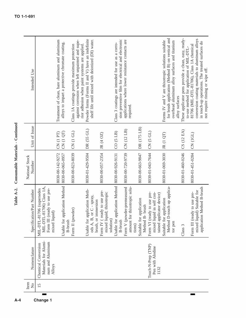
Tabl
eA
-2.
Con
sum
able
Mat
eria
ls-
Con
tinu
ed
Item No
Nom
encl
atur
eSp
ecifi
catio
n/Pa
rtN
umbe
rN
atio
nal
Stoc
kN
umbe
rU
nit
ofIs
sue
Inte
nded
Use
15C
hem
ical
Con
vers
ion
Mat
eria
lsfo
rA
lum
i-nu
man
dA
lum
inum
Allo
ys
MIL
-DT
L-8
1706
(sup
erse
des
MIL
-DT
L-8
1706
)C
lass
1A,
Form
III
(rea
dyto
use
pre-
mix
edliq
uid)
8030
-00-
142-
9272
CN
(1PT
)T
reat
men
tof
clea
n,ba
real
umin
uman
dal
umin
umal
loys
toim
part
apr
otec
tive
chro
mat
eco
atin
g.U
sabl
efo
rap
plic
atio
nM
etho
dB
-bru
sh80
30-0
0-06
5-09
57C
N(1
QT
)
Form
II(p
owde
r)80
30-0
0-82
3-80
39C
N(1
GL
)C
lass
1Aco
atin
gspr
ovid
em
axim
umpr
otec
tion
agai
nst
corr
osio
nw
hen
left
unpa
inte
dan
dsu
pe-
rior
adhe
sion
whe
npa
int
syst
ems
are
appl
ied.
Usa
ble
for
appl
icat
ion
Met
h-od
sA
,B
,or
C-
spra
y,br
ush,
orim
mer
sion
8030
-01-
429-
9504
DR
(55
GL
)Po
wde
rfo
rms
(For
ms
IIan
dV
)ha
vean
inde
finite
shel
flif
eun
tilm
ixed
with
deio
nize
d(D
I)w
ater
.
Form
IV(
read
yto
use
pre-
mix
edliq
uid;
thix
otro
pic
solu
tion)
8030
-00-
057-
2354
JR(4
OZ
)
Usa
ble
for
appl
icat
ion
Met
hod
B-b
rush
8030
-00-
926-
9131
CO
(5L
B)
Cla
ss3
coat
ings
are
inte
nded
for
use
asa
corr
o-si
onpr
even
tive
film
for
elec
tric
alan
del
ectr
onic
appl
icat
ions
whe
relo
wer
resi
stan
ceco
ntac
tsar
ere
quir
ed.
Form
V(p
owde
r-pr
emea
sure
dam
ount
for
thix
otro
pic
solu
-tio
ns)
8030
-00-
720-
9739
CN
(12
LB
)
Suita
ble
for
appl
icat
ion
Met
hod
B-
brus
h80
30-0
0-66
3-98
47D
R(1
75L
B)
Touc
h-N
-Pre
p(T
NP)
Pen
with
Alo
dine
1132
Form
VI
(rea
dyto
use
pre-
mix
edliq
uid
inse
lfco
n-ta
ined
appl
icat
orde
vice
)
8030
-01-
043-
7644
CN
(5G
L)
Suita
ble
for
appl
icat
ion
Met
hod
D-t
ouch
upap
plic
a-to
rpe
n
8030
-01-
069-
3030
JR(1
QT
)Fo
rms
IVan
dV
are
thix
otro
pic
solu
tions
suita
ble
for
brus
hap
plic
atio
n(M
etho
dB
)on
vert
ical
and
over
head
alum
inum
allo
ysu
rfac
esan
dtit
aniu
mal
loy
surf
aces
Cla
ss3
8030
-01-
460-
0246
CS
(12
EA
)T
hese
appl
icat
orpe
nspr
ovid
ea
clea
n,ea
sy,
read
y-to
-use
met
hod
for
appl
icat
ion
ofM
IL-D
TL
-81
706
(MIL
-DT
L-8
1706
),C
lass
1Ach
emic
alco
nver
sion
coat
ing
mat
eria
lsto
alum
inum
allo
ysin
touc
h-up
oper
atio
ns.
The
trea
ted
surf
aces
dono
tre
quir
eri
nsin
gor
wip
eof
f.
Form
III
(rea
dyto
use
pre-
mix
edliq
uid)
Suita
ble
for
appl
icat
ion
Met
hod
B-b
rush
8030
-01-
451-
0284
CN
(1G
L)
TO 1-1-691
A-4 Change 1

Tabl
eA
-2.
Con
sum
able
Mat
eria
ls-
Con
tinu
ed
Item No
Nom
encl
atur
eSp
ecifi
catio
n/Pa
rtN
umbe
rN
atio
nal
Stoc
kN
umbe
rU
nit
ofIs
sue
Inte
nded
Use
16C
hem
ical
Con
vers
ion
Mat
eria
lsfo
rA
lum
i-nu
man
dA
lum
inum
Allo
ys(n
on-
ferr
icya
nide
cata
-ly
zed)
MIL
-DT
L-8
1706
(sup
erse
des
MIL
-DT
L-8
1706
),C
lass
1A&
3
Non
-fer
ricy
anid
eco
nver
sion
coat
ing
for
the
trea
t-m
ent
ofcl
ean,
bare
alum
inum
allo
ysu
rfac
esto
impa
rta
chro
mat
eco
atin
gw
here
ferr
icya
nide
mat
eria
lsca
use
prob
lem
sfo
rth
elo
cal
was
tedi
spos
al/tr
eatm
ent
(sew
er)
syst
em.
Alo
dine
600,
Cla
ss1A
,Fo
rmII
,M
etho
dB
-bru
sh80
30-0
0-81
1-37
23B
T(2
LB
)
Alo
dine
600,
Cla
ss3,
Form
II,
Met
hod
B-b
rush
8030
-01-
018-
2838
CO
(10
LB
)
Tur
coat
Alu
mig
old,
Cla
ss1A
,Fo
rmII
,M
etho
dB
-bru
sh80
30-0
1-34
1-86
09C
B(1
25L
B)
17M
agne
sium
Allo
y,Pr
o-ce
sses
for
Pret
reat
-m
ent
and
Prev
entio
nof
Cor
rosi
onO
n(H
enke
lPr
oces
s)
SAE
AM
S-M
-317
1(s
uper
-se
des
MIL
-M-3
171)
Type
VI
(chr
omic
acid
brus
h-on
trea
tmen
t)
Tre
atm
ent
ofcl
ean,
bare
mag
nesi
uman
dits
allo
ysto
impa
rta
prot
ectiv
ech
rom
ate
coat
ing
usin
gth
isH
enke
lPr
oces
spr
emix
edre
ady
tous
ech
ro-
miu
mtr
ioxi
dean
dca
lciu
msu
lfat
em
ixtu
re.
The
inst
ruct
ions
for
prep
arin
gth
isso
lutio
nfr
ompo
wde
rs(C
hrom
ium
Tri
oxid
ean
dC
alci
umSu
l-fa
te)
-lis
ted
inIt
em#’
s18
and
19)
onsi
teca
nbe
foun
din
Cha
pter
5,Se
ctio
nII
ofth
ism
anua
l.
8030
-015
12–2
416
CO
(1Q
T)
18C
hrom
ium
Tri
oxid
e,Te
chni
cal
(Chr
omic
Aci
d)
A-A
-558
27(s
uper
sede
sO
-C-
303)
6810
-00-
264-
6517
CN
(5L
B)
One
oftw
och
emic
als
used
topr
epar
ea
mag
ne-
sium
conv
ersi
onco
atin
gso
lutio
n(S
AE
AM
S-M
-31
71,
Type
VI)
per
Cha
pter
5,Se
ctio
nII
ofth
ism
anua
l.19
Des
icca
nt,
Cal
cium
Sulf
ate,
Anh
ydro
us,
Tech
nica
l
O-D
-210
6810
-00-
242-
4066
CN
(1L
B)
One
oftw
och
emic
als
used
topr
epar
ea
mag
ne-
sium
conv
ersi
onco
atin
gso
lutio
n(S
AE
AM
S-M
-31
71,
Type
VI)
per
Cha
pter
5,Se
ctio
nII
ofth
ism
anua
l.
TO 1-1-691
Change 1 A-5

Tabl
eA
-2.
Con
sum
able
Mat
eria
ls-
Con
tinu
ed
Item No
Nom
encl
atur
eSp
ecifi
catio
n/Pa
rtN
umbe
rN
atio
nal
Stoc
kN
umbe
rU
nit
ofIs
sue
Inte
nded
Use
20C
orro
sion
Rem
ovin
gan
dM
etal
Con
ditio
n-in
gC
ompo
und
(Pho
spho
ric
Aci
dB
ase)
MIL
-C-1
0578
Aco
ncen
trat
edph
osph
oric
acid
solu
tion
whi
chis
dilu
ted
with
wat
eran
dus
edto
rem
ove
corr
osio
n/ru
stfr
omfe
rrou
sm
etal
surf
aces
and
slig
htly
etch
the
surf
ace
offe
rrou
san
dso
me
non-
ferr
ous
sur-
face
sto
prom
ote
adhe
sion
ofpa
int
syst
ems
and
CPC
’s.
Type
sI
&II
are
used
for
rust
rem
oval
from
ferr
ous
met
als
afte
rhe
avy,
encr
uste
dru
stis
rem
oved
mec
hani
cally
and
asa
surf
ace
cond
i-tio
ner
for
ferr
ous
and
som
eno
n-fe
rrou
sm
etal
surf
aces
prio
rto
pain
ting
orC
PCap
plic
atio
n.Ty
peI
rem
oves
mor
eru
stan
dre
quir
esri
nsin
gw
ithw
ater
,w
hile
Type
IIis
wip
edof
fw
ithcl
ean
rags
.Ty
peII
Iis
used
tore
mov
eru
stfr
omch
ro-
miu
mpl
ated
stee
lsu
rfac
es.
Type
Vis
used
tore
-m
ove
rust
from
ferr
ous
met
alpa
rts
imm
erse
din
adi
pta
nkaf
ter
all
grea
sean
doi
lha
vebe
encl
eane
dfr
omth
esu
rfac
es.
Type
I(W
ash-
off)
6850
-00-
270-
5551
BT
(1G
L)
6850
-00-
656-
1291
DR
(5G
L)
6850
-00-
926-
5298
DR
(15
GL
)
Tank
)Ty
peII
(Wip
e-of
f)68
50-0
0-17
4-96
72B
T(1
GL
)
6850
-00-
656-
1292
DR
(5G
L)
Type
III
(Inh
ibite
d)68
50-0
085
4-79
52D
R(5
GL
)
Type
V(I
mm
ersi
on68
50-0
1-10
7-25
51C
O(4
GL
)
6850
-00-
551-
9577
DR
(15
GL
)
Do
not
use
thes
em
ater
ials
onhi
ghst
reng
thst
eel
part
sas
they
can
caus
ehy
-dr
ogen
embr
ittle
men
t.
Cle
anin
gC
ompo
unds
21C
lean
ing
Com
poun
d:A
ircr
aft,
Ext
erio
rM
IL-P
RF-
8557
0
Type
I(G
ener
alpu
rpos
e,68
50-0
1-23
7-74
82C
N(5
GA
L)
Cle
anin
gof
pain
ted
and
unpa
inte
dai
rcra
ft,
mis
sile
,an
deq
uipm
ent
surf
aces
.C
heck
for
regu
lato
ryco
mpl
ianc
ebe
fore
usin
gTy
peI
beca
use
itco
n-ta
ins
arom
atic
solv
ents
.
arom
atic
solv
ent
base
d)68
50-0
1-23
7-80
03D
R(1
5G
AL
)
6850
-01-
237-
8004
DR
(55
GA
L)
Type
II(G
ener
alpu
rpos
e,68
50-0
1-23
9-05
71G
L(1
GA
L)
Cle
anin
gof
pain
ted
and
unpa
inte
dai
rcra
ft,
mis
sile
,an
deq
uipm
ent
surf
aces
.W
ater
base
dfo
rmul
am
aybe
used
onbo
thhi
ghgl
oss
and
cam
oufla
gepa
int
syst
ems.
non-
solv
ent
base
d)68
50-0
1-23
5-08
72C
N(5
GA
L)
6850
-01-
248-
9828
DR
(15
GA
L)
6850
-01-
236-
0128
DR
(55
GA
L)
TO 1-1-691
A-6

Tabl
eA
-2.
Con
sum
able
Mat
eria
ls-
Con
tinu
ed
Item No
Nom
encl
atur
eSp
ecifi
catio
n/Pa
rtN
umbe
rN
atio
nal
Stoc
kN
umbe
rU
nit
ofIs
sue
Inte
nded
Use
Type
III
(Abr
asiv
esp
otcl
eane
r)68
50-0
1-23
2-91
64C
N(5
GL
)U
seon
high
glos
spa
int
sche
me
coat
ings
tore
mov
est
ubbo
rnco
ntam
inan
tssu
chas
boot
mar
ksan
dsm
udge
sas
wel
las
gun
blas
tan
dex
haus
ttr
ack
soil.
21 Con
t.Ty
peIV
(Rub
beri
zed
spot
clea
ner)
6850
-01-
235-
0873
CN
(5G
AL
)U
seon
low
glos
s,ca
mou
flage
pain
tsc
hem
eco
atin
gsto
rem
ove
stub
born
cont
amin
ants
such
asbo
otm
arks
and
smud
ges
asw
ell
asgu
nbl
ast
and
ex-
haus
ttr
ack
soil.
6850
-01-
248-
9829
DR
(15
GA
L)
6850
-01-
248-
9830
DR
(55
GA
L)
Type
V(G
el-t
ype
clea
ner)
6850
-01-
234-
0219
CN
(5G
AL
)C
lean
ing
ofw
heel
wel
ls,
win
gbu
tts,
and
othe
rar
eas
whe
reco
mpl
ete
rins
ing
with
wat
erca
nbe
tole
r-at
ed.
Thi
xotr
opic
clea
ner
clin
gsto
vert
ical
orov
erhe
adsu
rfac
es.
6850
-01-
248-
9831
DR
(15
GA
L)
6850
-01-
235-
7458
DR
(55
GA
L)
22C
lean
ing
Com
poun
d,A
eros
pace
Equ
ip-
men
t
MIL
-PR
F-87
937
Type
I(T
erpe
neba
sed,
solv
ent
emul
sion
,w
ater
dilu
tabl
e)68
50-0
1-39
0-78
08C
N(1
GL
)Te
rpen
eba
sed.
Goo
dge
nera
lcl
eane
rfo
rhe
avily
soile
dca
mou
flage
and
high
glos
spa
inte
dar
eas
and
unpa
inte
dm
etal
surf
aces
.R
equi
res
adeq
uate
vent
ilatio
nan
dco
mpl
ete
rins
ing
ofen
trap
men
tar
eas.
May
requ
ire
airc
raft
SPD
and/
orm
issi
leor
equi
pmen
tSP
Map
prov
albe
fore
itis
used
.
6850
-01-
390-
7811
CN
(5G
L)
6850
-01-
390-
7816
DR
(55
GL
)68
50-0
1-46
1-00
65B
T(2
4O
Z)
Spra
yT
rig-
ger
Type
II(W
ater
dilu
tabl
ecl
ean-
ing
com
poun
d)68
50-0
1-39
0-78
27C
N(1
GL
)A
tpr
esen
t,th
isis
the
prim
ary
gene
ral
clea
ner
for
cam
oufla
gean
dgl
oss
pain
ted
and
unpa
inte
dm
etal
surf
aces
onai
rcra
ft,
mis
sile
s,an
deq
uipm
ent.
Itw
illbe
dele
ted
in20
05an
dre
plac
eden
tirel
yby
the
Type
IVcl
eane
r.
6850
-01-
339-
5227
CN
(5G
L)
6850
-01-
339-
5228
DR
(55
GL
)
Type
III
(Gel
type
clea
ning
com
poun
d)68
50-0
1-39
0-95
30C
N(5
GL
)V
isco
us,
thix
otro
pic
gel
clea
ner
for
very
heav
ilyso
iled
area
ssu
chas
airc
raft
cont
rol
surf
ace
and
whe
elw
ells
whe
rea
long
dwel
ltim
eis
requ
ired
.U
seon
lyin
area
sth
atto
lera
tehe
avy
rins
ing.
6850
-01-
390-
9453
DR
(55
GL
)
TO 1-1-691
A-7

Tabl
eA
-2.
Con
sum
able
Mat
eria
ls-
Con
tinu
ed
Item No
Nom
encl
atur
eSp
ecifi
catio
n/Pa
rtN
umbe
rN
atio
nal
Stoc
kN
umbe
rU
nit
ofIs
sue
Inte
nded
Use
22 Con
t.Ty
peIV
(Hea
vydu
ty,
wat
erdi
luta
ble
clea
ning
com
-po
und)
6850
-01-
429-
2368
CN
(1G
L)
Hea
vydu
tycl
eane
req
ually
suite
dfo
rhe
avily
soile
dar
eas
and
asa
gene
ral
clea
ner
for
clea
ning
cam
-ou
flage
and
glos
spa
inte
dan
dba
rem
etal
surf
aces
ofai
rcra
ft,
mis
sile
s,an
deq
uipm
ent.
In20
05,
itw
illco
mpl
etel
yre
plac
eTy
peII
clea
ner.
6850
-01-
433-
0873
CN
(5G
L)
6850
-01-
429-
2371
DR
(55
GL
)68
50-0
1-46
1-00
60B
T(2
4O
Z)
Spra
yT
rig-
ger
6850
-01-
461-
0070
CN
(16
OZ
)A
eros
ol23
Cle
anin
gC
ompo
unds
,A
ircr
aft
Surf
ace
MIL
-C-4
3616
6850
-01-
045-
7929
CN
(5G
L)
Aso
lven
tem
ulsi
onty
pecl
eane
rfo
rre
mov
alof
oily
and
grea
syso
ils.
The
Cla
ss1A
aero
sol
mat
eria
lis
anex
celle
ntsp
otcl
eane
rfo
rth
ese
type
sof
soils
.C
lass
1(l
iqui
d)68
50-0
1-04
5-79
30D
R(1
5G
L)
6850
-01-
045-
7931
DR
(55
GL
)C
lass
1A(l
iqui
d/
aero
sol)
6850
-01-
005-
5305
CN
(16
OZ
)A
eros
ol24
Cle
anin
gC
ompo
und:
Eng
ine
Gas
Path
Cle
aner
MIL
-PR
F-85
704
Rem
oves
accu
mul
ated
salt,
dirt
,an
doi
lyre
sidu
esfr
omth
ega
spa
thof
engi
nes.
Type
I(S
olve
ntem
ulsi
oncl
eane
rco
ncen
trat
ew
/hy-
droc
arbo
nso
lven
t)
6850
-00-
181-
7594
CN
(5G
L)
Solv
ent
conc
entr
ate
for
clea
ning
the
com
pres
sor
sect
ion
ofga
stu
rbin
een
gine
s(e
ngin
eof
f-lin
e;st
arte
rcr
anke
d).
6850
-00-
181-
7597
DR
(55
GL
)
Type
II(A
queo
uscl
eane
rco
n-ce
ntra
te)
6850
-01-
372-
8303
CN
(5G
L)
Aqu
eous
conc
entr
ate
for
clea
ning
the
com
pres
sor
sect
ion
ofga
stu
rbin
een
gine
s(e
ngin
eof
f-lin
e;st
arte
rcr
anke
d).
6850
-01-
372-
8304
DR
(55
GL
)
Type
IIR
TU
(Rea
dy-T
o-U
se)
6850
-01-
370-
5245
CN
(5G
L)
Rea
dyto
use
aque
ous
clea
ner
for
clea
ning
gas
tur-
bine
engi
nes
(eng
ine
off-
line;
star
ter
cran
ked)
.68
50-0
1-37
0-52
44D
R(5
5G
L)
Type
III
(Aqu
eous
clea
ner
conc
entr
ate
w/o
hydr
ocar
-bo
nso
lven
t)
6850
-01-
433-
6436
CN
(5G
L)
Aqu
eous
conc
entr
ate.
With
nohy
droc
arbo
nso
lven
tsfo
ron
-lin
e(fi
red)
clea
ning
ofga
stu
rbin
een
gine
sIA
Wsp
ecifi
cen
gine
mai
nten
ance
inst
ruct
ions
.68
50-0
1-43
3-64
38D
R(5
5G
L)
24 Con
t.Ty
peII
IR
TU
(Rea
dy-T
o-U
se)
6850
-01-
472-
1845
CN
(5G
L)
6850
-01-
472-
1846
DM
(55
GL
)
TO 1-1-691
A-8

Tabl
eA
-2.
Con
sum
able
Mat
eria
ls-
Con
tinu
ed
Item No
Nom
encl
atur
eSp
ecifi
catio
n/Pa
rtN
umbe
rN
atio
nal
Stoc
kN
umbe
rU
nit
ofIs
sue
Inte
nded
Use
25C
lean
ing
Com
poun
d,fo
rPa
rts
Was
hers
and
Spra
yC
abin
ets
MIL
-PR
F-29
602
(SA
EA
MS-
C-2
9602
)D
eter
gent
for
use
inpa
rts
was
hers
and
spra
yca
bi-
nets
tocl
ean
avia
tion
wea
pons
syst
ems,
engi
ne,
and
supp
ort
equi
pmen
tco
mpo
nent
s.R
emov
esgr
ease
,oi
l,an
ddi
rtw
hich
are
pres
ent
ondi
sas-
sem
bled
com
pone
nts.
Type
I(W
ater
solu
ble
liqui
dco
ncen
trat
e)68
50-0
1-43
1-22
69C
N(1
GA
L)
6850
-01-
431-
2267
CN
(5G
AL
)68
50-0
1-43
1-22
68D
R(5
5G
AL
)D
SF-1
,Te
lech
emIn
t’l
Inc
6850
-01-
524-
2956
BX
(4G
LC
onta
iner
s)P/
ND
SF-1
Hea
vyD
uty
6850
-01-
524-
2978
CO
(5L
B)
Aqu
eous
Part
sW
ashe
r,C
lean
eran
dD
egre
aser
6850
-01-
524-
2980
DR
(55
GL
)
.Ty
peII
(Wat
erso
lubl
epo
w-
der)
TH
EM
AT
ER
IAL
SL
IST
ED
BE
LO
WA
RE
AP
PR
OV
ED
FO
RU
SEO
NL
AN
DIN
GG
EA
RC
OM
PO
NE
NT
SA
ND
IVD
CO
AT
ED
HIG
HST
RE
NG
TH
STE
EL
PAR
TS
6850
-01-
053-
2789
CO
(1L
B)
Do
not
use
thes
ecl
eane
rson
airc
raft
land
-in
gge
arco
mpo
nent
s,w
heel
s,an
dbr
akes
,or
any
IVD
alum
inum
coat
edhi
ghst
reng
thst
eel
part
sas
they
may
caus
ehy
drog
enem
britt
lem
ent.
Use
only
mat
eri-
als
appr
oved
byan
dlis
ted
onth
ela
test
revi
sion
ofA
FD
raw
ing
#98
2501
9on
airc
raft
land
ing
gear
com
pone
nts,
whe
els,
and
brak
es,
and
onan
yot
her
IVD
alum
i-nu
mco
ated
high
stre
ngth
stee
lpa
rts.
6850
-01-
431-
9025
CO
(50
LB
)68
50-0
1-43
1-90
24D
R(4
00L
B)
(Zip
Che
mic
alPr
oduc
tsC
o;C
age
Cod
e#
1KQ
X9)
PNC
alla
-296
(Con
cent
rate
dem
ulsi
fyin
gty
peliq
uid
clea
ner)
6850
-01-
485-
5972
CO
(1G
L)
6850
-01-
485-
5932
CO
(5G
L)
6850
-01-
485-
5950
DR
(55
GL
)PN
Cal
la60
2LF
(Con
cen-
trat
edno
n-em
ulsi
fyin
gty
peliq
uid
clea
ner)
6850
-01-
513-
5230
CO
(1G
L)
6850
-01-
513-
5237
CO
(5G
L)
6850
-01-
513-
5233
DR
(55
GL
)
TO 1-1-691
Change 1 A-9
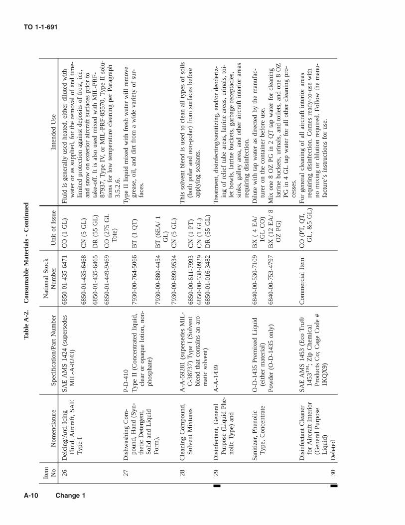
Tabl
eA
-2.
Con
sum
able
Mat
eria
ls-
Con
tinu
ed
Item No
Nom
encl
atur
eSp
ecifi
catio
n/Pa
rtN
umbe
rN
atio
nal
Stoc
kN
umbe
rU
nit
ofIs
sue
Inte
nded
Use
26D
eici
ng/A
nti-
Icin
gFl
uid,
Air
craf
t,SA
ETy
peI
SAE
AM
S14
24(s
uper
sede
sM
IL-A
-824
3)68
50-0
1-43
5-64
71C
O(1
GL
)Fl
uid
isge
nera
llyus
edhe
ated
,ei
ther
dilu
ted
with
wat
eror
assu
pplie
d,fo
rth
ere
mov
alof
and
time-
limite
dpr
otec
tion
agai
nst
depo
sits
offr
ost,
ice,
and
snow
onex
teri
orai
rcra
ftsu
rfac
espr
ior
tota
ke-o
ff.
Itis
also
used
mix
edw
ithM
IL-P
RF-
8793
7,Ty
peIV
,or
MIL
-PR
F-85
570,
Type
IIso
lu-
tions
for
low
tem
pera
ture
clea
ning
per
Para
grap
h3.
5.2.
6.
6850
-01-
435-
6468
CN
(5G
L)
6850
-01-
435-
6465
DR
(55
GL
)
6850
-01-
449-
9469
CO
(275
GL
Tote
)
27D
ishw
ashi
ngC
om-
poun
d,H
and
(Syn
-th
etic
Det
erge
nt,
Solid
and
Liq
uid
Form
),
P-D
-410
Type
IIliq
uid
mix
edw
ithfr
esh
wat
erw
illre
mov
egr
ease
,oi
l,an
ddi
rtfr
oma
wid
eva
riet
yof
sur-
face
s.Ty
peII
(Con
cent
rate
dliq
uid,
clea
ror
opaq
uelo
tion,
non-
phos
phat
e)
7930
-00-
764-
5066
BT
(1Q
T)
7930
-00-
880-
4454
BT
(6E
A/
1G
L)
7930
-00-
899-
9534
CN
(5G
L)
28C
lean
ing
Com
poun
d,So
lven
tM
ixtu
res
A-A
-592
81(s
uper
sede
sM
IL-
C-3
8737
)Ty
peI
(Sol
vent
blen
dth
atco
ntai
nsan
aro-
mat
icso
lven
t)
Thi
sso
lven
tbl
end
isus
edto
clea
nal
lty
pes
ofso
ils(b
oth
pola
ran
dno
n-po
lar)
from
surf
aces
befo
reap
plyi
ngse
alan
ts.
6850
-00-
611-
7993
CN
(1PT
)68
50-0
0-53
8-09
29C
N(1
GL
)68
50-0
1-01
6-34
82D
R(5
5G
L)
29D
isin
fect
ant,
Gen
eral
Purp
ose
(Liq
uid
Phe-
nolic
Type
)an
d
A-A
-143
9T
reat
men
t,di
sinf
ectin
g/sa
nitiz
ing,
and/
orde
oder
iz-
ing
ofre
lief
tube
area
s,la
trin
ear
eas,
urin
als,
toi-
let
bow
ls,
latr
ine
buck
ets,
garb
age
rece
ptac
les,
sink
s,ga
lley
area
,an
dot
her
airc
raft
inte
rior
area
sre
quir
ing
disi
nfec
tion.
Sani
tizer
,Ph
enol
icTy
pe,
Con
cent
rate
O-D
-143
5Pr
emix
edL
iqui
d(e
ither
mat
eria
l)68
40-0
0-53
0-71
09B
X(
4E
A/
1GL
CO
)D
ilute
with
tap
wat
eras
dire
cted
byth
em
anuf
ac-
ture
ron
the
cont
aine
rbe
fore
use.
Pow
der
(O-D
-143
5on
ly)
6840
-00-
753-
4797
BX
(12
EA
/8
OZ
PG)
Mix
one
8O
ZPG
in2
QT
tap
wat
erfo
rcl
eani
ngla
trin
ebu
cket
s,ur
inal
s,an
dto
ilets
,an
don
e8
OZ
PGin
4G
Lta
pw
ater
for
all
othe
rcl
eani
ngpr
o-ce
sses
.D
isin
fect
ant
Cle
aner
for
Air
craf
tIn
teri
or(G
ener
alPu
rpos
eL
iqui
d)
SAE
AM
S14
53(E
coT
ru®
1453
TM
;Z
ipC
hem
ical
Prod
ucts
Co;
Cag
eC
ode
#1K
QX
9)
Com
mer
cial
Item
CO
(PT,
QT,
GL
,&
5G
L)
For
gene
ral
clea
ning
ofal
lai
rcra
ftin
teri
orar
eas
requ
irin
gdi
sinf
ectio
n.C
omes
read
y-to
-use
with
nom
ixin
gor
dilu
tion
requ
ired
.Fo
llow
the
man
u-fa
ctur
e’s
inst
ruct
ions
for
use.
30D
elet
ed
TO 1-1-691
A-10 Change 1

Tabl
eA
-2.
Con
sum
able
Mat
eria
ls-
Con
tinu
ed
Item No
Nom
encl
atur
eSp
ecifi
catio
n/Pa
rtN
umbe
rN
atio
nal
Stoc
kN
umbe
rU
nit
ofIs
sue
Inte
nded
Use
31W
ater
Rep
elle
nt:
Win
-do
wan
dW
inds
hiel
d,G
lass
and
Plas
tic
SAE
AS
6882
(sup
erse
des
MIL
-W-6
882)
6850
-00-
139-
5297
BT
(8O
Z)
Ant
i-w
ettin
gfil
mfo
rex
teri
orgl
ass
orac
rylic
plas
ticw
indo
ws
and
win
dshi
elds
toas
sure
good
visi
bilit
yun
der
rain
yco
nditi
ons.
32Po
lish,
Met
al,A
lum
i-nu
mA
-A-5
9318
(sup
erse
des
MIL
-P-
6888
)Po
lishi
ngun
pain
ted
alum
inum
surf
aces
ofai
rcra
ft.
The
abra
sive
qual
ityof
the
polis
hen
able
sit
tore
mov
eta
rnis
han
dpr
oduc
ea
high
last
ing
shin
e.T
hepo
lish
shal
lno
tbe
used
onal
umin
umai
rcra
ftsu
rfac
esth
atar
eto
bepa
inte
d.
Type
I(L
iqui
d)79
30-0
0-26
6-71
31C
N(1
QT
)79
30-0
0-26
7-12
24C
N(1
GL
)Ty
peII
(Pas
te)
7930
-00-
734-
4010
CN
(1Q
T)
33Po
lish,
Plas
ticP-
P-56
0C
lean
ing
and
polis
hing
ofpl
astic
mat
eria
lsto
re-
mov
elig
htsc
ratc
hes,
and
inth
eap
plic
atio
nof
anan
tista
ticfil
mw
hich
will
prev
ent
the
elec
tros
tatic
attr
actio
nof
dust
,lin
t,as
h,et
c.,
toac
rylic
plas
ticsu
rfac
es.
Type
I(L
iqui
d)79
30-0
0-63
4-53
40B
T(1
PT)
7930
-00-
935-
3794
BX
(24
EA
8oz)
7930
-01-
133-
5375
BX
(1D
Z)
7930
-01-
115-
4744
CN
(1PT
)34
Era
sers
,R
ubbe
rA
-A-1
32(s
uper
sede
sZ
Z-E
-66
1)R
emov
alof
light
tarn
ish
orco
rros
ion
from
elec
tric
alco
nnec
tors
and
cont
acts
and
othe
rav
ioni
csco
m-
pone
nts.
Rec
tang
ular
with
beve
led
ends
(25/ 8
inL
x½
inW
x7/ 8
inT
7510
-00-
949-
5055
BX
(1D
Z)
Rec
tang
ular
(2in
Lx
¾in
Wx
7/ 8
inT
)75
10-0
0-32
3-87
88B
X(1
DZ
)
Cle
anin
gPa
ds/C
loth
s35
Face
Res
pira
tor
Cle
an-
ing
Wip
e(t
owel
ette
s)3M
Co.
PN50
4(C
age
Cod
e#
OT
1L6)
Hyg
ieni
ccl
eani
ngof
resp
irat
ors
and
othe
rpe
rson
alpr
otec
tive
gear
/equ
ipm
ent
(alc
ohol
-fre
efo
rmul
a).
11x
8.5
inW
ipes
4240
-01-
372-
3078
BX
(100
PK)
6510
-01-
397-
4339
CS
(5B
Xof
100
PK)
36C
lean
ing
Com
poun
d,O
ptic
alL
ens
(Rea
dyto
Use
)
A-A
-591
99(s
uper
sede
sM
IL-
C-4
3454
)C
lean
ing
ofex
pose
dop
tical
surf
aces
.
Type
I(2
0%al
coho
l)68
50-0
0-39
2-97
51B
T(2
OZ
)68
50-0
0-22
7-18
87B
T(1
QT
)Ty
peII
(57%
alco
hol)
6850
-00-
188-
9875
BT
(1Q
T)
37C
lean
er,
Pipe
PN:
8405
07(C
age
Cod
e#
6406
7)99
20-0
0-29
2-99
46B
X(1
344
EA
)C
lean
ing
smal
lor
ifice
san
dcr
evic
es
TO 1-1-691
A-11

Tabl
eA
-2.
Con
sum
able
Mat
eria
ls-
Con
tinu
ed
Item No
Nom
encl
atur
eSp
ecifi
catio
n/Pa
rtN
umbe
rN
atio
nal
Stoc
kN
umbe
rU
nit
ofIs
sue
Inte
nded
Use
38Pa
d,C
lean
ing
and
Pol-
ishi
ngN
on-m
etal
lic(f
orai
rcra
ftcl
eani
ngki
t)
A-A
-310
0(s
uper
sede
sM
IL-C
-83
957)
Non
-wov
en,
non-
met
allic
,no
n-ab
rasi
ve,
poly
este
rcl
eani
ngan
dpo
lishi
ngpa
ds(1
2″L
x6″
W)
for
use
onai
rcra
ft,
mis
sile
,an
deq
uipm
ent
surf
aces
.R
epla
cem
ent
pads
for
airc
raft
was
hki
t(A
ppen
dix
B,
Item
No.
1)
Type
I(3
/ 8in
T)
7920
-00-
151-
6120
PG(1
0SH
)
Type
II(1
inT
)79
20-0
0-17
1-15
34PG
(10
SH)
39A
ircr
aft
Cle
anin
gPa
ds3M
Co.
PN61
-500
1-87
94-5
6850
-01-
496-
4913
CS
(200
EA
)N
on-w
oven
,no
n-m
etal
lic,
non-
abra
sive
,po
lyes
ter
clea
ning
and
polis
hing
pads
with
impr
egna
ted
rubb
erpa
rtic
les
for
clea
ning
ofai
rcra
ft,
mis
sile
,an
deq
uipm
ent
surf
aces
.T
hese
pads
prov
ide
im-
prov
edcl
eani
ngef
ficie
ncy
over
the
Item
#38
pads
.
Scot
chbr
ite®
#33
(3½
x5
inpa
d
(Cag
eC
ode
#(I
m-
prov
edTy
pe)
7638
1)3M
#96
1;PN
61-5
000-
4615
-8(3
½x
5in
pad
hold
er-
hand
held
)
Loc
alPu
rcha
seC
S(1
0E
A)
3MC
o.PN
61-5
001-
8795
-268
50-0
1-49
6-49
03C
S(1
00E
A)
(45/ 8
x10
inpa
d3M
#250
;PN
61-5
000-
4913
-7(4
5/ 8
x10
inpa
dho
lder
-han
dhe
ld)
Loc
alPu
rcha
seC
S(5
EA
)
3MC
o.PN
61-5
001-
8796
-068
50-0
1-49
6-49
01C
S(5
0E
A)
(6x
12in
pad)
3M#2
61;
PN61
-500
0-32
35-6
(6x
12in
pad
hold
er-
hand
le
6850
-01-
499-
5307
CS
(1E
A)
Mel
amin
ePa
ds3.
5″X
5″X
1.2″
7920
-01-
526-
9015
BX
(200
EA
)4.
625″
X10
″X
1.3″
7920
-01-
526-
9007
BX
(100
EA
)4.
625″
X10
″X
1.2″
7920
-01-
526-
9003
BX
(10
EA
)6″
X12
″X
1.3″
7920
-01-
526-
9003
BX
(50
EA
)3″
X5″
X1″
6850
-00-
525-
7684
BX
(6E
A)
40C
ham
ois
Lea
ther
,Sh
eeps
kin,
Oil
Tann
ed
KK
-C-3
00G
ener
alpu
rpos
ew
ashi
ngan
dpo
lishi
ng
Gra
deB
,C
lass
2,Si
ze-
smal
l83
30-0
0-82
3-75
45PG
(5E
A)
TO 1-1-691
A-12 Change 1

Tabl
eA
-2.
Con
sum
able
Mat
eria
ls-
Con
tinu
ed
Item No
Nom
encl
atur
eSp
ecifi
catio
n/Pa
rtN
umbe
rN
atio
nal
Stoc
kN
umbe
rU
nit
ofIs
sue
Inte
nded
Use
41C
hees
eclo
th,
Cot
ton,
Ble
ache
dan
dU
n-bl
each
ed
CC
C-C
-440
Cle
anin
gan
dpo
lishi
ngai
rcra
ft,
mis
sile
,an
deq
uip-
men
tsu
rfac
es.
Type
I,C
lass
2(b
leac
hed)
8305
-00-
262-
3321
BO
(36
inx
50Y
D)
8305
-00-
205-
3495
BO
(36
inx
100
YD
)Ty
peI,
Cla
ss1
(unb
leac
hed)
8305
-00-
222-
2423
PG(3
8.5
inx
1Y
D)
Type
II,
Cla
ss2
(ble
ache
d)83
05-0
0-20
5-34
96PG
(36
inx
10Y
D)
8305
-00-
267-
3015
PG(3
6in
x1
YD
)42
Clo
th,
Cle
anin
g,N
on-
wov
enFa
bric
CC
C-C
-46
Gen
eral
clea
ning
(e.g
.w
ipin
gup
grea
sean
dliq
uid
spill
s)w
here
low
resi
dual
surf
ace
cont
amin
atio
nis
requ
ired
.Ty
peI
(Unt
reat
ed)
Cla
ss1
(Lig
htdu
ty)
8305
-00-
753-
2967
RO
(36
inx
50Y
D)
Cla
ss4
(Ext
rahe
avy
duty
)79
20-0
0-29
2-92
04B
X(M
X)-
150
in2
EA
7920
-01-
130-
7738
PG(H
D)
-12
x15
inE
AC
lass
6(L
ight
duty
,pe
rfor
ated
orno
n-pe
rfor
ated
)79
20-0
0-40
1-80
34B
X(H
D)
-150
in2
EA
Cla
ss7
(Air
craf
tso
lven
tw
iper
)79
20-0
1-18
0-05
5618
BX
(150
EA
-8¾
x8¼
in)
7920
-01-
180-
0557
BX
(800
EA
-16
¾in
x20
¾in
)
TO 1-1-691
Change 1 A-13

Tabl
eA
-2.
Con
sum
able
Mat
eria
ls-
Con
tinu
ed
Item No
Nom
encl
atur
eSp
ecifi
catio
n/Pa
rtN
umbe
rN
atio
nal
Stoc
kN
umbe
rU
nit
ofIs
sue
Inte
nded
Use
43C
loth
es,
Cle
anin
gfo
rA
ircr
aft
Prim
ary
and
Seco
ndar
ySt
ruct
ural
Surf
aces
SAE
AM
S38
19;
Cla
ss2,
Gra
deA
(Dup
ont-
Sont
ara®
AC
TM
Air
craf
tW
ipes
;D
is-
trib
utor
-C
age
Cod
e#
1BL
94)
Use
dfo
rcl
eani
ngsu
rfac
esre
quir
ing
exce
ptio
nally
low
resi
dual
surf
ace
cont
amin
atio
n.
PNA
C91
6568
50-0
1-48
7-28
598B
X(1
00E
A-
9x
16½
in)
PNA
C12
165
6850
-01-
487-
2861
BX
(250
EA
-12
x16
½in
)44
Clo
th:
Flan
nel,
Cot
ton
(Blu
ein
colo
r)A
-A-5
0129
(sup
erse
des
CC
C-
C-4
58)
8305
-00-
913-
5817
BO
(50
YD
)C
lean
ing
and
polis
hing
ofpl
astic
surf
aces
such
asca
nopi
es,
win
dscr
eens
,et
c.45
Clo
th:
Cle
anin
g,L
ow-
Lin
tA
-A-5
9323
Hyd
raul
iccl
ean
room
and
fluid
syst
ems
clea
ning
.
(Whi
tein
colo
r)(s
uper
sede
sM
IL-C
-850
43)
Type
I(C
lean
room
use
-ultr
a-cl
ean,
low
lint
wip
es)
7920
-00-
165-
7195
BX
(10
LB
)
Do
not
use
thes
ecl
oths
with
flam
mab
leso
lven
tsas
fire
may
resu
ltw
hen
used
with
thes
eso
lven
ts.
Type
II(G
ener
alus
ere
quir
ing
low
lint,
high
lyab
sorb
ent
wip
esbu
tno
tto
clea
nro
omst
anda
rds)
7920
-00-
044-
9281
BX
(10
LB
)
Cor
rosi
onPr
even
tive
Com
poun
ds,
Oils
,G
reas
es,
and
Lub
rica
nts
46C
orro
sion
Prev
entiv
eC
ompo
und,
Solv
ent
Cut
back
,C
old
App
li-ca
tion
MIL
-PR
F-16
173
(sup
erse
des
MIL
-C-1
6173
)
Cla
ssII
,G
rade
1-
Har
dFi
lm(L
owV
OC
≤2.8
#/G
L)
8030
-01-
396-
5731
CN
(1PT
)T
hick
,w
ax-l
ike,
hard
film
cons
iste
ncy
for
long
term
prot
ectio
nof
met
alsu
rfac
esag
ains
tco
rros
ion
with
orw
ithou
tco
veri
ngs
(ind
oors
orou
tdoo
rs).
Thi
sm
ater
ial
will
crac
kan
dsp
all
off
the
surf
ace
ator
belo
wa
tem
pera
ture
of0°
F(-
18°
C).
8030
-01-
396-
5732
CN
(1G
L)
8030
-01-
347-
0970
CN
(5G
L)
8030
-01-
396-
5237
DR
(55
GL
)
TO 1-1-691
A-14 Change 1

Tabl
eA
-2.
Con
sum
able
Mat
eria
ls-
Con
tinu
ed
Item No
Nom
encl
atur
eSp
ecifi
catio
n/Pa
rtN
umbe
rN
atio
nal
Stoc
kN
umbe
rU
nit
ofIs
sue
Inte
nded
Use
46 Con
t.C
lass
I,G
rade
2-
Soft
film
(Hig
hV
OC
>2.
8#/
GL
)80
30-0
0-11
8-06
66C
N(1
1O
Z)
Aer
osol
Thi
ck,
grea
se-l
ike
cons
iste
ncy
for
prot
ectin
gm
etal
surf
aces
agai
nst
corr
osio
ndu
ring
rew
ork
orst
or-
age.
Incl
udes
exte
nded
indo
orpr
otec
tion
ofin
te-
rior
orex
teri
orsu
rfac
esw
ithou
tth
eus
eof
barr
ier
mat
eria
ls.
For
outd
oor
prot
ectio
n,th
ism
ater
ial
can
only
beus
edfo
ra
limite
dtim
ew
here
tem
-pe
ratu
reis
not
extr
emel
yho
t.It
will
adhe
reto
surf
aces
and
prov
ide
prot
ectio
nat
tem
pera
ture
sdo
wn
to-4
0°F
(-40
°C
)
8030
-01-
149-
1731
CN
(1Q
T)
8030
-00-
244-
1297
CN
(1G
AL
)
8030
-00-
244-
1298
CN
(5G
AL
)
8030
-00-
244-
1295
DR
(55
GL
)
Cla
ssII
,G
rade
3-
Soft
oily
film
(Low
VO
C≤2
.8#/
GL
)80
30-0
1-39
6-57
35C
N(1
PT)
Soft
,oi
lym
ater
ial
used
todi
spla
cew
ater
,in
clud
ing
salt
wat
er,
from
met
alsu
rfac
esan
djo
int
area
san
dto
prot
ect
them
from
corr
osio
nfo
rlim
ited
peri
ods
(30
days
orle
ss).
Use
dto
prot
ect
criti
cal
bare
stee
lan
dph
osph
ated
stee
lsu
rfac
esof
part
saw
ait-
ing
repa
iror
bein
gsh
ippe
dto
ade
pot
for
repa
ir.Pr
ovid
esin
defin
itepr
otec
tion
for
part
sw
ithin
seal
edba
rrie
rm
ater
ial
cont
aine
rs.
8030
-01-
396-
5748
CN
(1G
L)
8030
-01-
347-
0971
CN
(5G
L)
8030
-01-
396-
5734
DR
(55
GL
)
Cla
ssII
,G
rade
4(T
rans
par-
ent,
non-
tack
yso
ftfil
m)
8030
-01-
396-
5738
CN
(1PT
)T
hin,
tran
spar
ent,
wat
erdi
spla
cing
,ta
ck-f
ree
prot
ec-
tive
film
for
prot
ectio
nof
met
alsu
rfac
esag
ains
tco
rros
ion
duri
ngin
door
stor
age
orw
hen
loca
ted
inin
teri
orar
eas
ofai
rcra
ft,
mis
sile
s,or
equi
pmen
tan
dfo
rlim
ited
outd
oor
pres
erva
tion.
Use
onco
n-tr
olca
bles
,fa
sten
ers,
bare
met
alar
eas,
oran
y-w
here
tem
pora
ry(3
0da
ysor
less
)pr
otec
tion
isne
eded
and
for
long
term
stor
age
ofpa
rts
with
inse
aled
barr
ier
mat
eria
lco
ntai
ner.
Itw
illad
here
tosu
rfac
esan
dpr
ovid
epr
otec
tion
atte
mpe
ratu
res
dow
nto
-40°
F(-
40°
C).
8030
-01-
396-
5743
CN
(1G
L)
8030
-01-
347-
0972
CN
(5G
L)
8030
-01-
396-
5736
DR
(55
GL
)
47C
orro
sion
Prev
entiv
eM
IL-D
TL
-850
54Te
mpo
rary
repa
irof
smal
lpa
int
dam
age
area
sfr
omch
ips,
scra
tche
s,or
crac
ks.
Inte
nded
for
use
onno
n-m
ovin
gpa
rts
not
requ
irin
ga
lubr
icat
edsu
r-fa
ce,
such
asfa
sten
ers,
seam
s,ac
cess
pane
ls,
join
ts,
unpa
inte
dm
etal
,et
c.D
ries
toa
hard
film
.
TO 1-1-691
Change 1 A-15

Tabl
eA
-2.
Con
sum
able
Mat
eria
ls-
Con
tinu
ed
Item No
Nom
encl
atur
eSp
ecifi
catio
n/Pa
rtN
umbe
rN
atio
nal
Stoc
kN
umbe
rU
nit
ofIs
sue
Inte
nded
Use
47 Con
t.C
ompo
und
(AM
L-
GU
AR
D)
Type
I(P
ress
uriz
ed/a
eros
olca
n)C
lass
134A
HC
FCpr
o-pe
llant
8030
-01-
066-
3971
CN
(12
OZ
)
8030
-01-
041-
1596
CN
(16
OZ
)80
30-0
1-34
7-09
79C
N(1
4O
Z)
Type
II(B
ulk
form
)80
30-0
1-34
7-09
83B
T(3
2O
Z-
pum
psp
ray)
8030
-01-
347-
0981
CN
(1Q
T)
8030
-01-
347-
0982
CN
(5G
L)
48C
orro
sion
Prev
entiv
eM
IL-P
RF-
8130
9W
ater
disp
laci
ngC
PCw
hich
may
beap
plie
dby
dipp
ing,
spra
ying
,br
ushi
ng,
orfr
ompr
essu
rize
dco
ntai
ners
.C
ompo
unds
,W
ater
Dis
plac
ing,
Ultr
a-T
hin
Film
Type
II(S
oft
film
)C
lass
1(N
on-p
ress
uriz
edco
n-ta
iner
/bul
k)80
30-0
0-21
3-32
79C
N(1
GL
)Su
itabl
efo
rus
eon
any
met
alsu
rfac
eex
cept
avio
n-ic
s/el
ectr
onic
sap
plic
atio
nsfo
rin
door
and
shor
tte
rmou
tdoo
rpr
otec
tion
whe
resu
rfac
esca
nbe
re-c
oate
dw
hen
requ
ired
.80
30-0
0-26
2-73
58C
N(5
GL
)N
OT
E
Itsh
ould
not
beus
edar
ound
LO
Xfit
tings
.
8030
-00-
524-
9487
DR
(55
GL
)C
lass
2,G
rade
CO
2(P
ress
ur-
ized
cont
aine
r-C
O2
prop
el-
lant
)
8030
-00-
938-
1947
CN
(16
OZ
)
Type
III
(Sof
tfil
m;A
vion
icgr
ade)
Wat
erdi
spla
cing
CPC
for
use
onav
ioni
ceq
uipm
ent,
elec
tric
alco
nnec
tor
plug
s,an
dco
ntac
tpo
ints
.C
lass
1(N
on-p
ress
uriz
edco
n-ta
iner
-bu
lk)
8030
-01-
347-
0978
CN
(1G
AL
)
Cla
ss2
(Pre
ssur
ized
cont
aine
r/ae
roso
l-
non
OD
Spr
opel
-la
nt)
8030
-00-
546-
8637
CN
(16
OZ
)
TO 1-1-691
A-16 Change 1

Tabl
eA
-2.
Con
sum
able
Mat
eria
ls-
Con
tinu
ed
Item No
Nom
encl
atur
eSp
ecifi
catio
n/Pa
rtN
umbe
rN
atio
nal
Stoc
kN
umbe
rU
nit
ofIs
sue
Inte
nded
Use
49L
ubri
cant
s,C
orro
sion
Prev
entiv
eC
om-
poun
d,W
ater
Dis
-pl
acin
g,Sy
nthe
tic
MIL
-L-8
7177
Wat
erdi
spla
cing
CPC
whi
chm
aybe
appl
ied
bydi
ppin
g,br
ushi
ng,
orsp
rayi
ng(p
ump
spra
yer
orae
roso
lsp
ray)
.Su
itabl
efo
rus
eon
any
met
alsu
r-fa
cein
clud
ing
avio
nics
/ele
ctro
nics
equi
pmen
t,el
ectr
ical
conn
ecto
r/pl
ugs,
and
cont
act
poin
tsfo
rin
door
and
shor
tte
rmou
tdoo
rpr
otec
tion
whe
resu
rfac
esca
nbe
re-c
oate
dw
hen
requ
ired
.It
can
beus
edas
anal
tern
ate/
subs
titut
efo
rM
IL-P
RF-
8130
9,Ty
pes
IIan
dII
I.
Type
I(P
ress
uriz
edca
n/A
ero-
sol)
;G
rade
B(W
ithad
ded
corr
osio
nin
hibi
tor)
6850
-01-
328-
3617
CN
(16
OZ
)
Type
II(N
on-p
ress
uriz
edco
n-ta
iner
/bu
lk);
Gra
deB
(With
adde
dco
rros
ion
in-
hibi
tor)
6850
-01-
326-
7294
CN
(5L
)
Do
not
use
arou
ndL
OX
fittin
gsas
fire
may
resu
lt.
50C
orro
sion
Prev
entiv
eC
ompo
und
(Hig
hZ
inc
Dus
tC
onte
ntPa
int)
Com
mer
cial
Prod
uct
Ahi
ghzi
ncdu
stco
nten
tep
oxy
pain
tty
peco
rros
ion
prev
entiv
eco
mpo
und
(als
okn
own
as“c
old
galv
a-ni
ze”)
used
for
repa
irof
defe
cts
inga
lvan
ized
coat
ings
,to
over
coat
wel
ded
area
son
galv
aniz
edst
eel,
and
topr
ovid
eco
rros
ion
for
area
sw
here
corr
osio
nw
asre
mov
edon
stee
lst
ruct
ures
ofsu
p-po
rteq
uipm
ent,
elec
tron
icva
ns,
ante
nna
tow
ers,
and
vehi
cles
.
ZR
CPr
od.
Co.
(Cag
eC
ode
#07
957)
8030
-01-
384-
9932
CN
(1Q
T)
PN82
81-1
0002
ZR
CPr
od.
Co.
(Cag
eC
ode
#07
957)
8030
-01-
015-
1550
CN
(12
OZ
)A
eros
olPN
8281
-100
00D
evco
nC
orp.
(Cag
eC
ode
#160
59)
8010
-00-
501-
5798
CN
(16
OZ
)A
eros
olPN
DE
VC
ON
Z&
NH
CC
orp.
(Cag
eC
ode
#20
913)
PNH
Y-Z
INC
Dev
con
Cor
p.(C
age
Cod
e#
1605
9PN
’s17
03&
1203
080
10-0
0-36
0-33
69C
N(1
GL
)
TO 1-1-691
Change 1 A-17

Tabl
eA
-2.
Con
sum
able
Mat
eria
ls-
Con
tinu
ed
Item No
Nom
encl
atur
eSp
ecifi
catio
n/Pa
rtN
umbe
rN
atio
nal
Stoc
kN
umbe
rU
nit
ofIs
sue
Inte
nded
Use
51L
ubri
catin
gO
il,G
en-
eral
Purp
ose,
Pres
er-
vativ
e(W
ater
Dis
-pl
acin
g,L
owTe
mpe
ratu
re)
MIL
-PR
F-32
033
(sup
erse
des
VV
-L-8
00)
9150
-00-
836-
8641
BT
(½O
Z)
Age
nera
lpu
rpos
e,w
ater
disp
laci
ng,
low
tem
pera
-tu
rera
ted
(-40
°F
/-4
0°C
)oi
lth
atca
nbe
appl
ied
bydi
ppin
g,br
ushi
ng,
orsp
rayi
ngfo
rlu
bric
atin
gan
dsh
ort
term
corr
osio
npr
otec
tion
ofm
etal
part
s;ai
rcra
ft,
mis
sile
,an
deq
uipm
ent
hing
es;
and
smal
lar
ms.
9150
-00-
261-
8146
BT
(1O
Z)
9150
-00-
273-
2389
CN
(4O
Z)
9150
-00-
458-
0075
CN
(16
OZ
)A
eros
ol91
50-0
1-37
4-20
21B
T(1
6O
Z)
Pum
pSp
ray
9150
-00-
231-
6689
CN
(1Q
T)
9150
-00-
231-
9045
CN
(1G
L)
9150
-00-
231-
9062
CN
(5G
L)
9150
-00-
281-
2060
DR
(55
GL
)52
Lub
rica
nt,
Cle
aner
and
Pres
erva
tive
for
Wea
pons
and
Wea
p-on
sSy
stem
s(C
LP)
MIL
-PR
F-63
460
9150
-01-
102-
1473
BT
(½O
Z)
Lub
rica
tion
and
shor
tte
rmpr
eser
vatio
nof
airc
raft
,m
issi
le,
and
equi
pmen
thi
nges
,an
dsm
all
and
larg
eca
liber
wea
pons
.C
anbe
used
asan
alte
rnat
eor
subs
titut
efo
rM
IL-P
RF-
3203
3(V
V-L
-800
).91
50-0
1-07
9-61
24B
T(4
OZ
)
Do
not
use
MIL
-PR
F-63
460
onru
bber
orot
her
elas
tom
eric
mat
eria
lsas
itm
ayda
mag
eth
em.
Use
only
inar
eas
whe
reth
eco
ntai
ned
solv
ents
can
read
ilyev
apor
ate.
9150
-01-
054-
6453
BT
(16
OZ
)Pu
mp
Spra
y
9150
-01-
327-
9631
BT
(32
OZ
)Pu
mp
Spra
y
9150
-01-
053-
6688
BT
(1G
L)
TO 1-1-691
A-18 Change 1

Tabl
eA
-2.
Con
sum
able
Mat
eria
ls-
Con
tinu
ed
Item No
Nom
encl
atur
eSp
ecifi
catio
n/Pa
rtN
umbe
rN
atio
nal
Stoc
kN
umbe
rU
nit
ofIs
sue
Inte
nded
Use
53C
orro
sion
Prev
entiv
eC
ompo
und,
Petr
o-le
um,
Hot
App
lica-
tion
MIL
-C-1
1796
Pres
erva
tion
ofin
teri
orsu
rfac
esof
unse
aled
stru
c-tu
ral
stee
lan
dal
umin
umal
loy
tubi
ngas
sem
blie
san
dot
her
met
alar
eas
that
mus
tre
mai
nba
rean
dar
eex
pose
dto
eith
erex
teri
oror
inte
rior
envi
ron-
men
tsin
serv
ice.
Cla
ss1
and
1Am
ater
ials
can
beus
edto
prot
ect
met
alpa
rts
inun
shie
lded
outd
oor
stor
age
orus
efo
rlim
ited
peri
ods
(90
days
)an
dun
limite
din
door
use
orst
orag
eei
ther
pack
aged
orun
pack
-age
d.C
lass
3m
ater
ials
can
beus
edto
prot
ect
part
ssu
chas
anti-
fric
tion
bear
ings
inin
-do
orst
orag
e.Pr
efer
ably
,us
eon
lyC
lass
1Am
ate-
rial
son
inse
rvic
est
ruct
ures
asth
eyar
eno
n-sl
ick
and
won
’tco
llect
dirt
asw
ell
asre
sist
ing
high
eram
bien
tte
mpe
ratu
res
(+15
0°F
/+
66°
C)
with
out
mel
ting
and
runn
ing
off
surf
aces
tow
hich
itis
appl
ied.
Cla
ss1
(Har
dfil
mco
mpo
und)
8030
-00-
231-
2354
CN
(5L
B)
8030
-00-
597-
3288
CN
(35
LB
)
8030
-00-
231-
2352
DR
(400
LB
)
Cla
ss1A
(Har
dfil
m,
non-
slic
kco
mpo
und)
8030
-00-
823-
8054
CN
(35
LB
)
8030
-00-
514-
1843
DR
(400
LB
)
Cla
ss3
(Sof
tfil
mco
mpo
und)
8030
-00-
598-
5915
CN
(1PT
)
8030
-00-
231-
2353
CN
(5L
B)
8030
-00-
285-
1570
CN
(35
LB
)
54L
inse
edO
il,B
oile
dA
STM
D26
0,Ty
peI
8010
-00-
244-
8961
CN
(1PT
)Pr
eser
vatio
nof
inte
rior
surf
aces
ofse
aled
stru
ctur
alca
rbon
stee
ltu
bing
asse
mbl
ies.
(sup
erse
des
A-A
-371
)80
10-0
0-15
2-32
45C
N(1
GL
)80
10-0
0-68
4-87
89C
N(5
GL
)80
10-0
0-24
2-61
14D
R(5
5G
L)
LU
BR
ICA
NT
S55
Gre
ase:
Air
craf
t,G
en-
eral
Purp
ose,
Wid
eTe
mpe
ratu
re
MIL
-PR
F-81
322
(sup
erse
des
MIL
-L-8
1322
)L
ubri
catin
gai
rcra
ftar
rest
ing
gear
shea
vesp
acer
san
dot
her
equi
pmen
tth
atop
erat
eun
der
high
con-
tact
load
san
dhi
ghsl
idin
gsp
eeds
.R
ange
(-65
°to
+35
0°F/
-54°
to+
177°
C)
NA
TO
Cod
eG
395
NG
LI
Gra
de1
9150
-01-
378-
0744
TU
(8O
Z)
9150
-01-
378-
0559
CN
(1.7
5L
B)
9150
-01-
378-
0693
CN
(6.5
LB
)N
GL
IG
rade
291
50-0
0-18
1-77
24T
U(8
OZ
)L
ubri
catin
gai
rcra
ftw
heel
bear
ings
and
inte
rnal
brak
ew
heel
asse
mbl
ies,
anti-
fric
tion
bear
ings
,ge
arbo
xes,
and
plai
nbe
arin
gs.
9150
-01-
262-
3358
CA
(14
OZ
)91
50-0
0-94
4-89
53C
N(1
.75
LB
)
TO 1-1-691
A-19

Tabl
eA
-2.
Con
sum
able
Mat
eria
ls-
Con
tinu
ed
Item No
Nom
encl
atur
eSp
ecifi
catio
n/Pa
rtN
umbe
rN
atio
nal
Stoc
kN
umbe
rU
nit
ofIs
sue
Inte
nded
Use
56G
reas
e:A
ircr
aft
and
Inst
rum
ent,
Gea
ran
dA
ctua
tor
Scre
w(-
100°
to+
250°
F/-
73°
to+
121°
C)
NA
TO
Cod
eG
354
MIL
-PR
F-23
827
(sup
erse
des
MIL
-G-2
3827
Lub
rica
ntfo
rus
ein
ball,
rolle
ran
dne
edle
bear
ings
,ge
ars,
and
onsl
idin
gan
dro
lling
surf
aces
ofsu
cheq
uipm
ent
asin
stru
men
ts,
cam
eras
,el
ectr
onic
gear
s,an
dai
rcra
ftco
ntro
lsy
stem
sth
atar
esu
bjec
tto
extr
eme
mar
ine
and
low
tem
pera
ture
cond
i-tio
ns.
It’s
extr
emel
ylo
wvo
latil
itypr
even
tsit
from
fogg
ing
upop
tical
inst
rum
ents
.It
can
beus
edfo
rro
lling
and
slid
ing
surf
aces
ofeq
uipm
ent
havi
nglo
wm
otiv
atin
gpo
wer
(low
torq
ueeq
uip-
men
t).A
lso
inte
nded
for
gene
ral
use
onai
rcra
ft,
mis
sile
,an
deq
uipm
ent
gear
s,ac
tuat
orsc
rew
s,an
dot
her
equi
pmen
tre
quir
ing
alu
bric
ant
with
high
load
carr
ying
capa
city
.
Type
I(M
etal
licso
apth
ick-
ened
)91
50-0
0-98
5-72
44T
U(4
OZ
)
9150
-00-
985-
7245
TU
(8O
Z)
9150
-00-
935-
4017
CA
(14
OZ
)
9150
-00-
985-
7246
CN
(1.7
5L
B)
9150
-00-
985-
7247
CN
(6.5
LB
)
9150
-00-
985-
7248
CN
(35
LB
)
57G
reas
e:Pl
ugV
alve
,G
asol
ine
Oil,
and
Wat
erR
esis
tant
SAE
AM
S-G
-603
2(s
uper
-se
des
MIL
-G-6
032)
Lub
rica
tion
ofta
pere
dpl
ugva
lves
.T
hetw
oty
pes
prov
ide
for
the
use
inhi
ghpr
essu
relu
bric
atio
neq
uipm
ent
orfo
rse
rvic
ing
thos
eva
lves
whi
chre
quir
ea
stic
kty
pelu
bric
ant.
Als
om
aybe
used
asa
gask
etlu
bric
ant
orse
alan
dfo
rge
nera
lpl
ugva
lve
serv
ice
insy
stem
sw
here
gaso
line,
oil,
alco
-ho
l,or
wat
erre
sist
ance
isre
quir
ed.
NA
TO
Cod
eG
363
Type
I(B
ulk
form
)91
50-0
0-19
0-09
26C
N(8
OZ
)
9150
-00-
257-
5360
CN
(1.7
5L
B)
Type
II(S
tick
form
)C
lass
A(¼
Dx
7/ 8
inL
)91
50-0
0-26
1-82
87B
X(2
4E
A)
Cla
ssB
(13/
32D
x1-
3/ 8
inL
)91
50-0
0-26
1-82
89B
X(2
4E
A)
Cla
ssC
(35/
64D
x2
inL
)91
50-0
0-26
1-82
90B
X(2
4E
A)
Cla
ssD
(21/
32D
x2-
7/16
inL
)91
50-0
0-26
1-82
91B
X(2
4E
A)
Cla
ssG
(55/
64D
x3-
3/ 8
inL
)91
50-0
0-26
1-82
92B
X(2
4E
A)
TO 1-1-691
A-20

Tabl
eA
-2.
Con
sum
able
Mat
eria
ls-
Con
tinu
ed
Item No
Nom
encl
atur
eSp
ecifi
catio
n/Pa
rtN
umbe
rN
atio
nal
Stoc
kN
umbe
rU
nit
ofIs
sue
Inte
nded
Use
58G
reas
e:A
ircr
aft
and
Inst
rum
ent,
Fuel
and
Oxi
dize
rR
esis
tant
MIL
-PR
F-27
617
(sup
erse
des
MIL
-G-2
7617
)L
ubri
catio
nof
tape
rpl
ugva
lves
,ga
sket
s,an
dbe
ar-
ings
infu
elsy
stem
sof
airc
raft
and
grou
ndsu
p-po
rteq
uipm
ent.
Als
osu
itabl
efo
rus
ein
LO
Xsy
s-te
ms
asa
lubr
ican
tfo
rva
lves
,th
read
s,an
dbe
arin
gsin
aero
spac
eve
hicl
esan
dsu
ppor
teq
uip-
men
t.M
ayno
tbe
suita
ble
for
alum
inum
and
mag
nesi
umdy
nam
icbe
arin
glu
bric
atio
nbe
caus
eof
poss
ible
igni
tion
haza
rds.
Type
III
ism
ore
com
mon
lykn
own
as“K
ryto
x”an
dis
LO
Xco
m-
patib
le.
Type
I-
NA
TO
Cod
e39
7(-
65°
to+
400°
F/-5
4°to
+20
4°C
)
9150
-01-
007-
4384
TU
(8O
Z)
9150
-01-
311-
9771
CN
(1.7
5L
B)
9150
-01-
088-
0498
TU
(2O
Z)
Type
II-
NA
TO
Cod
eG
398
(-40
°to
+40
0°F/
-40°
to+
204°
C)
9150
-00-
961-
8995
TU
(8O
Z)
9150
-01-
358-
5154
CN
(1L
B)
Type
III
-N
AT
OC
ode
G39
9(-
30°
to+
400°
F/-3
4°to
+20
4°C
)
9150
-01-
353-
5788
CR
(1L
B)
Type
IV-
NA
TO
Cod
eG
1350
(-10
0°to
+40
0°F/
-73°
to+
204°
C)
9150
-01-
393-
1749
TU
(2O
Z)
59G
reas
e:M
olyb
denu
mD
isul
fide,
Low
and
Hig
hTe
mpe
ratu
res;
NA
TO
Cod
eG
353
(-10
0°to
+25
0°F/
-73
°to
+12
1°C
)
MIL
-G-2
1164
9150
-00-
935-
4018
CA
(14
OZ
)L
ubri
cant
for
acce
ssor
ysp
lines
,he
avy
load
edsl
id-
ing
stee
lsu
rfac
es,
orfo
ran
ti-fr
ictio
nbe
arin
gsca
rryi
nghi
ghlo
ads
and
oper
atin
gth
roug
hw
ide
tem
pera
ture
rang
esw
here
mol
ybde
num
disu
lfide
will
prev
ent
orde
lay
seiz
ure
inth
eev
ent
ofin
ad-
equa
telu
bric
atio
n.Sh
ould
not
beus
edfo
rw
heel
bear
ings
orfo
rot
her
than
stee
lsu
rfac
esw
ithou
tau
thor
izat
ion.
9150
-00-
754-
2595
CN
(1.7
5L
B)
9150
-00-
223-
4004
CN
(6.5
LB
)
9150
-00-
965-
2003
CN
(35
LB
)
9150
-01-
219-
1629
DR
(20
KG
)
60G
reas
e:Pn
eum
atic
Sys-
tem
;N
AT
OC
ode
G39
2
SAE
AM
S-G
-434
3(s
uper
-se
des
MIL
-G-4
343)
9150
-00-
119-
9291
TU
(2O
Z)
Lub
rica
ntbe
twee
nru
bber
and
met
alpa
rts
ofpn
eu-
mat
icsy
stem
s.It
may
also
beus
edfo
rpr
essu
rize
dca
bin
bulk
-hea
dgr
omm
ets
and
othe
rm
echa
nism
sre
quir
ing
rubb
erto
met
allu
bric
atio
n.91
50-0
0-26
9-82
55C
N(1
.75
LB
)
TO 1-1-691
A-21

Tabl
eA
-2.
Con
sum
able
Mat
eria
ls-
Con
tinu
ed
Item No
Nom
encl
atur
eSp
eci c
atio
n/Pa
rtN
umbe
rN
atio
nal
Stoc
kN
umbe
rU
nit
ofIs
sue
Inte
nded
Use
61G
reas
e:A
ircr
aft,
Hel
i-co
pter
Osc
illat
ing
Bea
ring
;N
AT
O
MIL
-G-2
5537
9150
-00-
478-
0055
CA
(14
OZ
)L
ubri
catio
nof
bear
ings
havi
ngos
cilla
tory
mot
ion
ofsm
all
ampl
itude
.
Cod
eG
366
(-65
°to
160°
F/-5
4°to
+71
°C
)
9150
-00-
616-
9020
CN
(1.7
5L
B)
9150
-00-
721-
8570
CN
(6.5
LB
)91
50-0
0-72
1-85
81C
N(3
5L
B)
62G
reas
e,A
ircr
aft,
Bal
lan
dR
olle
rB
eari
ng;
NA
TO
Cod
eG
372
(-10
0°to
450°
F/-7
3°to
+232
°C
)
MIL
-G-2
5013
9150
-00-
823-
8048
TU
(8O
Z)
Bal
lan
dro
ller
bear
ing
lubr
icat
ion.
Itm
aybe
used
onai
rcra
ftac
tuat
ors
and
gear
boxe
s,an
dot
her
sim
ilar
equi
pmen
tan
dan
ti-fr
ictio
nbe
arin
gsw
here
oper
atio
nof
low
torq
ueeq
uipm
ent
requ
ires
lubr
i-ca
tion
for
exte
nded
peri
ods
oftim
ew
hen
auth
o-ri
zed
byth
eap
plic
able
syst
emsp
eci c
mai
nte-
nanc
em
anua
l.
9150
-00-
935-
4019
CA
(14
OZ
)
9150
-01-
234-
5866
CN
(1L
B)
9150
-00-
141-
6770
CN
(1.7
5L
B)
9150
-00-
141-
6771
CN
(35
LB
)
63L
ubri
cant
,M
olyb
de-
num
Dis
ul d
e,Si
li-co
ne;
NA
TO
Cod
eS
1735
DO
D-L
-256
8191
50-0
0-54
3-72
20L
B(1
LB
)L
ubri
cant
for
use
onsl
ow-s
peed
slid
ing
surf
aces
inai
rcra
ftga
stu
rbin
een
gine
san
dot
her
area
sof
airc
raft
,m
issi
les
and
equi
pmen
tsu
bjec
tto
high
tem
pera
ture
s(u
pto
+752
°F/
+40
0°C
)an
das
anan
ti-se
ize
com
poun
don
thre
aded
part
sw
hich
op-
erat
eat
tem
pera
ture
sup
to+1
400°
F(7
60°
C).
64L
ubri
cant
:So
lidFi
lm,
Hea
t-C
ured
,C
orro
-si
onIn
hibi
ting
SAE
AS5
272,
Type
sI
&II
(rep
lace
sM
IL-P
RF-
4601
0,Ty
pes
I&
II)
Lub
rica
ntfo
rus
eto
redu
cew
ear
and
prev
ent
gall-
ing,
corr
osio
n,an
dse
izur
eof
met
als.
Idea
lfo
rsl
idin
gm
otio
nap
plic
atio
nssu
chas
plai
nan
dsp
heri
cal
bear
ings
, a
ptr
acks
,hi
nges
,th
read
,an
dca
msu
rfac
es.
Itis
also
usef
ulw
here
aso
lven
tre
sist
ant
coat
ing
isre
quir
ed,
lubr
icat
ion
and
corr
o-si
onpr
otec
tion
for
area
sth
atex
peri
ence
slig
htvi
brat
ory
mot
ion,
lubr
icat
ion
and
corr
osio
npr
o-te
ctio
nof
mec
hani
sms
havi
ngin
freq
uent
oper
a-tio
nin
terv
als
orlif
etim
elu
bric
atio
n,an
dw
here
long
-ter
mco
rros
ion
prot
ectio
nis
need
edun
der
stat
icco
nditi
ons.
TO 1-1-691
A-22 Change 1

Tabl
eA
-2.
Con
sum
able
Mat
eria
ls-
Con
tinu
ed
Item No
Nom
encl
atur
eSp
ecifi
catio
n/Pa
rtN
umbe
rN
atio
nal
Stoc
kN
umbe
rU
nit
ofIs
sue
Inte
nded
Use
64 Con
t.Ty
peI
(cur
e@
+30
0°F
/+14
9°C
)91
50-0
0-83
4-56
08C
N(1
PT)
NO
TE
SAE
AS5
272,
Type
Ian
dM
IL-P
RF-
4601
0cu
red
at+
300°
F(+
149°
C)
are
usab
leon
all
met
alsu
rfac
es,
but
SAE
AS5
272,
Type
IIan
dM
IL-P
RF-
4601
0cu
red
at+
400°
F(+
204°
C)
shou
ldno
tbe
used
onal
umin
umal
loys
orot
her
met
als
adve
rsel
yaf
fect
edby
expo
sure
toth
ishi
gher
tem
pera
ture
.B
efor
eus
ing
MIL
-PR
F-46
010
(alo
wV
OC
mat
eria
l)in
lieu
ofSA
EA
S527
2,Ty
pes
Ian
dII
,au
thor
i-za
tion
from
the
airc
raft
SPD
orth
em
is-
sile
oreq
uipm
ent
SPM
isre
quir
ed.
Do
not
use
thes
em
ater
ials
onro
ller
bear
ings
orin
area
sex
pose
dto
LO
X.
9150
-00-
985-
7255
CN
(1G
L)
Type
II(c
ure
@+
400°
F/+
205°
C)
9150
-00-
948-
6912
CN
(1Q
T)
9150
-00-
948-
7025
CN
(1G
L)
MIL
-PR
F-46
010
(sup
erse
des
MIL
-PR
F-46
010,
Type
III)
Col
or1
(Nat
ural
)91
50-0
1-41
6-95
06C
N(1
GL
)C
olor
2(B
lack
)91
50-0
1-41
6-95
09C
N(1
GL
)65
Lub
rica
nt,
Solid
Film
,A
ir-C
ured
,C
orro
sion
Inhi
bitin
g;N
AT
OC
ode
S74
9
MIL
-L-2
3398
Lub
rica
ntca
nbe
appl
ied
bydi
ppin
g,br
ushi
ng,
orsp
rayi
ngfo
rus
eon
stee
l,tit
aniu
m,
oral
umin
umbe
arin
gsu
rfac
esw
here
mod
erat
ew
ear
life
and
corr
osio
npr
otec
tion
isde
sire
d.It
issu
itabl
efo
rsl
idin
gm
otio
nap
plic
atio
nssu
chas
inpl
ain
sphe
rica
lbe
arin
gs,
flap
trac
ks,
hing
esan
dca
msu
rfac
es,
espe
cial
lyw
here
itis
not
feas
ible
tous
eth
ety
peof
solid
film
lubr
ican
tw
hich
requ
ires
baki
ngat
anel
evat
edte
mpe
ratu
re.
Use
dto
repa
irde
fect
sin
SAE
AS5
272
and
MIL
-PR
F-46
010
coat
ings
.
Type
I(B
ulk)
9150
-00-
954-
7422
CN
(1Q
T)
Type
II(P
ress
uriz
edSp
ray)
9150
-01-
260-
2534
CN
(16
OZ
)A
eros
ol
MIL
-PR
F-46
147
Type
I(1
8ho
urcu
re)
Form
1(B
ulk)
Col
or1
(Nat
ural
)91
50-0
1-36
0-19
07C
N(1
QT
)
9150
-01-
142-
9361
CN
(1G
L)
Col
or2
(Bla
ck)
9150
-01-
360-
1908
CN
(1Q
T)
9150
-01-
360-
1909
CN
(1G
L)
TO 1-1-691
Change 1 A-23

Tabl
eA
-2.
Con
sum
able
Mat
eria
ls-
Con
tinu
ed
Item No
Nom
encl
atur
eSp
ecifi
catio
n/Pa
rtN
umbe
rN
atio
nal
Stoc
kN
umbe
rU
nit
ofIs
sue
Inte
nded
Use
Form
2(P
ress
uriz
edSp
ray)
Col
or1
(Nat
ural
)91
50-0
1-36
0-19
03C
N(1
2O
Z)
Aer
osol
9150
-01-
360-
1905
CN
(16
OZ
)A
eros
olC
olor
2(B
lack
)91
50-0
1-36
0-19
04C
N(1
2O
Z)
Aer
osol
9150
-01-
360-
1906
CN
(16
OZ
)A
eros
ol
Neu
tral
izin
gA
gent
san
dIn
dica
tor
Mat
eria
ls66
Fire
Ext
ingu
ishi
ngA
gent
,Aqu
eous
Film
Form
ing
Foam
(AFF
F)L
iqui
dC
on-
cent
rate
,fo
rFr
esh
and
Sea
Wat
er
MIL
-F-2
4385
Con
cent
rate
isin
tend
edfo
rus
ein
mec
hani
cal
foam
gene
ratin
geq
uipm
ent
such
asfir
efig
htin
gtr
ucks
orfo
amsp
rink
ler
syst
ems
for
extin
guis
hing
fires
.D
ilute
and
use
the
AFF
Fag
ent
with
fres
hw
ater
inth
efo
llow
ing
prop
ortio
nto
achi
eve
optim
umpe
rfor
man
ce:
Type
3-3
part
sof
conc
entr
ate
to97
part
sw
ater
byvo
lum
e;an
dTy
pe6-
6pa
rts
con-
cent
rate
to94
part
sw
ater
byvo
lum
e.
Type
342
10-0
1-13
9-49
72C
N(5
GA
L)
4210
-01-
144-
0291
DR
(55
GA
L)
Type
642
10-0
1-05
6-83
43C
N(5
GA
L)
4210
-01-
056-
0883
DR
(55
GA
L)
67A
mm
oniu
mH
ydro
xide
,Te
chni
cal
A-A
5937
0(s
uper
sede
sO
-A-
451)
Use
das
ane
utra
lizin
gag
ent
for
acid
sin
urin
e.
Type
I(2
0to
30%
asam
mo-
nia)
6810
-00-
584-
3793
BT
(1PT
)
6810
-00-
817-
9929
BT
(1G
L)
Type
III
(9to
10%
asam
mo-
nia)
6810
-00-
527-
2476
BT
(1Q
T)
68So
dium
Bic
arbo
nate
,Te
chni
cal
(Bak
ing
Soda
)
A-A
-374
(AST
MD
928)
6810
-00-
264-
6618
BX
(1L
B)
Use
dto
neut
raliz
esu
lfur
icac
idel
ectr
olyt
ede
posi
tsfr
omle
ad-a
cid
batte
ries
.68
10-0
0-29
7-00
92B
G(5
0L
B)
69So
dium
Phos
phat
e,M
onob
asic
,Anh
y-dr
ous,
Tech
nica
l
AN
SI/A
WW
AB
504
(sup
er-
sede
sM
IL-S
-137
27)
6810
-00-
281-
1858
BG
(100
LB
)U
sed
tone
utra
lize
pota
ssiu
mhy
drox
ide
elec
trol
yte
depo
sits
from
nick
el-c
adm
ium
batte
ries
.
70B
oric
Aci
dA
-A-5
9282
(sup
erse
des
O-C
-26
5)68
10-0
0-26
4-65
35B
T(5
00G
M)
Use
tone
utra
lize
pota
ssiu
mhy
drox
ide
elec
trol
yte
depo
sits
from
nick
el-c
adm
ium
batte
ries
.68
10-0
0-82
4-90
90B
T(3
KG
)68
10-0
0-97
3-57
16B
T(1
LB
)68
10-0
0-15
3-01
91B
X(2
5L
B)
TO 1-1-691
A-24
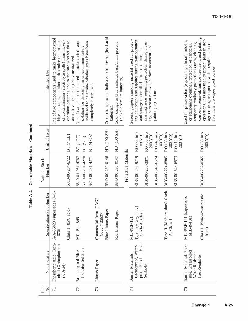
Tabl
eA
-2.
Con
sum
able
Mat
eria
ls-
Con
tinu
ed
Item No
Nom
encl
atur
eSp
ecifi
catio
n/Pa
rtN
umbe
rN
atio
nal
Stoc
kN
umbe
rU
nit
ofIs
sue
Inte
nded
Use
71Ph
osph
oric
Aci
d,Te
ch-
nica
l(O
rtho
phos
pho-
ric
Aci
d)
A-A
-558
20(s
uper
sede
sO
-O-
670)
One
oftw
oco
mpo
nent
sus
edto
mak
ebr
omot
hym
olbl
uein
dica
ting
solu
tion
tode
term
ine
the
loca
tion
ofco
ntam
inat
ion
(ele
ctro
lyte
spill
s)fr
omni
ckel
-ca
dmiu
mba
tteri
esan
dto
indi
cate
whe
ther
thes
ear
eas
have
been
com
plet
ely
neut
raliz
ed.
Cla
ss1
(85%
acid
)68
10-0
0-26
4-67
22B
T(7
LB
)
72B
rom
othy
mol
Blu
eIn
dica
tor
Solu
tion
MIL
-B-1
1845
6810
-01-
031-
4757
BT
(1PT
)O
neof
two
com
pone
nts
used
tom
ake
anin
dica
tor
solu
tion
for
dete
ctin
gni
ckel
-cad
miu
mba
ttery
spill
san
dto
dete
rmin
ew
heth
erar
eas
have
been
com
plet
ely
neut
raliz
ed.
6810
-00-
281-
4270
BT
(½L
)
6810
-00-
281-
4271
BT
(4O
Z)
73L
itmus
Pape
rC
omm
erci
alIt
em-C
AG
EC
ode
#22
537
Blu
eL
itmus
Pape
r66
40-0
0-29
0-01
46H
D(1
00SH
)C
olor
chan
geto
red
indi
cate
sac
idpr
esen
t(l
ead
acid
batte
ries
).R
edL
itmus
Pape
r66
40-0
0-29
0-01
47H
D(1
00SH
)C
olor
chan
geto
blue
indi
cate
sba
se/a
lkal
ipr
esen
t(n
icke
l-ca
dmiu
mba
tteri
es).
Prot
ectiv
eM
ater
ials
74B
arri
erM
ater
ials
,G
reas
epro
of,
Wat
er-
proo
f,Fl
exib
le,
Hea
t-Se
alab
le
MIL
-PR
F-12
1G
ener
alpu
rpos
em
aski
ngm
ater
ial
used
for
prot
ect-
ing
equi
pmen
tan
dsu
pplie
sdu
ring
tran
spor
tatio
nan
dst
orag
eun
der
all
clim
ate
cond
ition
s,an
dm
aski
ngar
eas
requ
irin
gpr
otec
tion
duri
ngcl
ean-
ing,
corr
osio
nre
mov
al,
surf
ace
trea
tmen
t,an
dpa
intin
gop
erat
ions
.
Type
I(H
eavy
duty
)G
rade
A,
Cla
ss1
8135
-00-
292-
9719
RO
(36
inx
100
YD
)81
35-0
0-23
3-38
71R
O(3
6in
x20
0Y
D)
8135
-00-
543-
6574
RO
(48
inx
100
YD
)Ty
peII
(Med
ium
duty
)G
rade
A,
Cla
ss1
8135
-00-
224-
8885
RO
(36
inx
200
YD
)81
35-0
0-54
3-65
73R
O(1
2in
x20
0Y
D)
75B
arri
erM
ater
ial,
Flex
-ib
le,
Gre
asep
roof
Wat
erR
esis
tant
,H
eat-
Seal
able
MIL
-PR
F-13
1(s
uper
sede
sM
IL-B
-131
)U
sed
for
pres
erva
tion
(e.g
.se
alin
gai
rcra
ft,
mis
sile
,or
equi
pmen
top
enin
gs,
prot
ectio
nof
cano
pies
,te
mpo
rary
wal
kway
prot
ectio
n)du
ring
clea
ning
,co
rros
ion
rem
oval
,su
rfac
etr
eatm
ent,
and
pain
ting
oper
atio
ns.
Itis
also
used
topr
otec
tpa
rts
inst
or-
age
orbe
ing
tran
spor
ted
whi
chre
quir
ean
abso
-lu
tem
oist
ure
vapo
rpr
oof
barr
ier.
Cla
ss1
(Non
-wov
enpl
astic
back
)81
35-0
0-28
2-05
65R
O(3
6in
x20
0Y
D)
TO 1-1-691
Change 1 A-25

Tabl
eA
-2.
Con
sum
able
Mat
eria
ls-
Con
tinu
ed
Item No
Nom
encl
atur
eSp
ecifi
catio
n/Pa
rtN
umbe
rN
atio
nal
Stoc
kN
umbe
rU
nit
ofIs
sue
Inte
nded
Use
NO
TE
Alw
ays
inst
all
with
the
plas
ticco
ated
side
tow
ard
the
part
and/
orsu
rfac
e.
76K
raft
Pape
r,U
ntre
ated
,(B
row
nin
colo
r)A
-A-2
03(s
uper
sede
sU
U-P
-26
8)G
ener
alw
rapp
ing
appl
icat
ions
and
prot
ectio
nof
surr
ound
ing
surf
ace
area
sdu
ring
abra
sive
blas
t-in
g,sp
ray
pain
ting,
seal
ant
appl
icat
ion,
etc.
,w
here
aw
ater
proo
fan
d/or
moi
stur
eva
por
proo
fm
aski
ngm
ater
ial
isno
tre
quir
ed.
Styl
e1
(She
ets)
30po
und
basi
sw
eigh
t81
35-0
0-29
0-34
08SH
(2x
3ft
;85
0E
A)
70po
und
basi
sw
eigh
t81
35-0
0-29
0-55
04SH
(3x
4ft
;20
0E
A)
Styl
e2
(Rol
ls)
50po
und
basi
sw
eigh
t81
35-0
1-33
7-53
70R
O(3
x20
0ft
)76 Con
t.81
35-0
0-16
0-77
64R
O(3
x98
0ft
)60
poun
dba
sis
wei
ght
8135
-00-
160-
7768
RO
(3x
820
ft)
8135
-00-
160-
7769
RO
(4x
820
ft)
70po
und
basi
sw
eigh
t81
35-0
0-16
0-77
71R
O(3
x70
0ft
)81
35-0
0-16
0-77
72R
O(4
x70
0ft
)80
poun
dba
sis
wei
ght
8135
-00-
160-
7776
RO
(3x
615
ft)
8135
-00-
160-
7778
RO
(4x
615
ft)
77Pa
int
Mas
king
Pape
rw
ithA
dhes
ive
Bac
k(L
ight
brow
nin
colo
r)
Rea
dy-M
askt
TM
(3M
Co.
/CA
GE
Cod
e#
5215
2PN
850D
C)
Ope
nPu
rcha
seR
O(2
inx
180
ft)
Pape
rm
aski
ngta
pew
ithad
hesi
veal
ong
one
edge
.Pr
otec
tssu
rfac
esfr
ompa
int
spla
tters
and
over
-sp
ray.
Eas
yto
appl
yan
dco
mes
off
clea
nly
with
noad
hesi
vetr
ansf
er.
Ope
nPu
rcha
seR
O(3
inx
400
ft)
Ope
nPu
rcha
seR
O(3
¼in
x75
ft)
TO 1-1-691
A-26

Tabl
eA
-2.
Con
sum
able
Mat
eria
ls-
Con
tinu
ed
Item No
Nom
encl
atur
eSp
ecifi
catio
n/Pa
rtN
umbe
rN
atio
nal
Stoc
kN
umbe
rU
nit
ofIs
sue
Inte
nded
Use
78Pl
astic
Shee
t,Po
lyol
e-fin
(Cle
ar)
A-A
-317
4(s
uper
cede
sL
-P-
378)
8135
-01-
066-
3217
RO
(6ft
x10
0ft
)Pr
otec
tion
ofac
rylic
airc
raft
cano
pies
duri
ngw
ash-
ing
oper
atio
ns.
Type
I(N
orm
alst
reng
thpo
ly-
ethy
lene
),C
lass
1(n
on-f
ood
use)
,G
rade
A(l
owsl
ip),
Fini
sh1
(unt
reat
ed)
79Ta
pes,
Pres
sure
Sens
i-tiv
eA
dhes
ive,
Pres
-er
vatio
nan
dSe
alin
g(B
lack
inco
lor)
SAE
AM
S-T-
2208
5(s
uper
-se
des
MIL
-T-2
2085
)75
10-0
0-85
2-81
79R
O(1
inx
36Y
D)
Plas
ticpr
eser
vatio
nan
dse
alin
gta
peus
edfo
rho
ld-
ing
mos
tba
rrie
rm
ater
ials
inpl
ace
duri
ngst
orag
eor
ship
men
tan
dcl
eani
ngan
dco
rros
ion
rem
oval
oper
atio
ns.
Eff
ectiv
efo
rm
any
outd
oor
appl
ica-
tions
and
can
beus
edon
met
als
orpa
inte
dsu
r-fa
ces
with
clea
nre
mov
alup
to2
year
saf
ter
ini-
tial
use.
7510
-00-
852-
8180
RO
(2in
x36
YD
)Ty
peII
(use
w/
orw
/oan
over
coat
ing)
7510
-00-
885-
3510
RO
(2½
inx
36Y
D)
7510
-00-
926-
8939
RO
(3in
x36
YD
)(3
MC
o./C
AG
EC
ode
#52
152
PN48
1)75
10-0
0-91
6-96
59R
O(4
inx
36Y
D)
7510
-00-
926-
8941
RO
(6in
x36
YD
)N
OT
E
Do
not
use
onac
rylic
orpo
lyca
rbon
ate
cano
pies
and
win
dscr
eens
.
TO 1-1-691
A-27

Tabl
eA
-2.
Con
sum
able
Mat
eria
ls-
Con
tinu
ed
Item No
Nom
encl
atur
eSp
ecifi
catio
n/Pa
rtN
umbe
rN
atio
nal
Stoc
kN
umbe
rU
nit
ofIs
sue
Inte
nded
Use
80Ta
pes,
Pres
sure
Sens
i-tiv
eA
dhes
ive,
Mas
k-in
g,N
on-S
tain
ing,
for
Air
craf
tPa
intin
gA
pplic
atio
ns
SAE
AM
S-T-
2159
5(s
uper
-se
des
MIL
-T-2
1595
)C
onfo
rmab
lecr
eped
pape
rta
peus
edfo
rm
aski
ngof
eith
erfla
tor
cont
oure
dsu
rfac
espr
ior
topa
intin
gan
dse
alan
tap
plic
atio
ns.
Tape
can
beus
edat
bak-
ing
tem
pera
ture
sup
to+
250°
F(+
121°
C)
for
one
hour
and
can
bere
mov
edw
ithou
tad
hesi
vetr
ans-
fer.
Tape
shal
lno
tbe
subj
ecte
dto
prol
onge
dpe
ri-
ods
ofou
tdoo
rex
posu
reor
sunl
ight
beca
use
itw
illbe
com
eve
rydi
fficu
ltto
rem
ove
and
will
leav
eta
pean
dad
hesi
vere
sidu
es.
Type
I(C
repe
dpa
per
back
ing)
(3M
Co.
/CA
GE
Cod
e#
5215
2PN
231/
Nat
ural
Col
or)
7510
-01-
371-
3239
RO
(½in
x60
YD
)75
10-0
1-37
1-32
34R
O(¾
inx
60Y
D)
7510
-01-
371-
3238
RO
(1in
x60
YD
)75
10-0
1-37
1-32
36R
O(1
½in
x60
YD
)75
10-0
1-37
1-32
37R
O(2
inx
60Y
D)
7510
-01-
371-
3235
RO
(3in
x60
YD
)Ty
peII
I(P
last
icba
ckin
g)(3
MC
o./C
AG
EC
ode
#52
152
PN21
8/L
ight
Gre
enC
olor
;Fi
neL
ine
Tape
®)
7510
-01-
158-
0035
RO
(¼in
x60
YD
)T
hin
plas
ticta
peus
edfo
rfin
elin
em
aski
ng,
inpa
r-tic
ular
whe
reco
lor
sepa
ratio
nis
invo
lved
,an
ddu
ring
pain
tto
uch-
up,
and
for
othe
rm
aski
ngan
dho
ldin
gap
plic
atio
ns.
Tape
shal
lno
tbe
subj
ecte
dto
prol
onge
dpe
riod
sof
outd
oor
expo
sure
orsu
n-lig
htbe
caus
eit
will
beco
me
very
diffi
cult
tore
-m
ove,
and
will
leav
eta
pean
dad
hesi
vere
sidu
es
7510
-01-
158-
6606
RO
(½in
x60
YD
)75
10-0
1-15
8-77
78R
O(¾
inx
60Y
D)
7510
-01-
158-
6605
RO
(1in
x60
YD
)75
10-0
1-15
8-66
04R
O(1
½in
x60
YD
)75
10-0
1-15
8-66
03R
O(2
inx
60Y
D)
7510
-01-
158-
6607
RO
(3in
x60
YD
)
TO 1-1-691
A-28

Tabl
eA
-2.
Con
sum
able
Mat
eria
ls-
Con
tinu
ed
Item No
Nom
encl
atur
eSp
ecifi
catio
n/Pa
rtN
umbe
rN
atio
nal
Stoc
kN
umbe
rU
nit
ofIs
sue
Inte
nded
Use
81Ta
pes,
Pres
sure
Sens
i-tiv
eA
dhes
ive,
for
Mas
king
Dur
ing
Pain
tR
emov
alO
p-er
atio
ns
SAE
AM
S-T-
2339
7(s
uper
-se
des
MIL
-T-2
3397
)A
lum
inum
foil
back
mas
king
tape
used
for
prot
ect-
ing
surr
ound
ing
surf
aces
duri
ngpa
int
rem
oval
oper
atio
nsan
dch
emic
alan
dso
me
mec
hani
cal
corr
osio
nre
mov
alop
erat
ions
.Alu
min
umba
ckin
gpr
ovid
esex
celle
ntre
flect
ion
ofbo
thhe
atan
dlig
ht.
Tape
can
beus
edei
ther
indo
ors
orou
tdoo
rsfo
rm
any
long
term
appl
icat
ions
.U
seta
pean
dde
cal
appl
icat
or,
Item
#84
,to
appl
yth
ista
peto
surf
aces
.
Type
II(A
lum
inum
foil
back
-in
g-
72ho
urpr
otec
tion)
7510
-00-
806-
4669
RO
(½in
x60
YD
)75
10-0
0-65
4-98
11R
O(¾
inx
60Y
D)
7510
-00-
720-
7516
RO
(1in
x60
YD
)(3
MC
o./C
AG
EC
ode
#52
152
PN42
5)75
10-0
0-68
4-88
03R
O(2
inx
60Y
D)
NO
TE
Use
only
3mC
o.PN
425
tape
for
airc
raft
chem
ical
pain
tre
mov
alop
erat
ions
,as
all
othe
rta
pes
will
not
hold
upfo
rth
ese
ex-
tend
eddw
ell
time
oper
atio
ns.
7510
-00-
816-
8077
RO
(3in
x60
YD
)75
10-0
0-98
2-39
55R
O(4
inx
60Y
D)
7510
-01-
179-
0662
RO
(6in
x60
YD
)82
Tape
s,Pr
essu
reSe
nsi-
tive
Adh
esiv
e,M
ask-
ing
A-A
-883
(sup
erse
des
PPP-
T-42
)Ty
peII
(Fla
tpa
per
back
ing)
7510
-01-
026-
4661
RO
(½in
x60
YD
)T
his
solv
ent
resi
stan
tta
peis
idea
lfo
rst
raig
htlin
epa
int
mas
king
oper
atio
ns.
The
1in
wid
thof
the
3MC
o.PN
250
tape
isth
ere
quir
edta
pefo
rpe
r-fo
rmin
gth
epa
int
wet
tape
adhe
sion
test
.B
ecau
seof
itshi
ghst
reng
th,
itis
good
for
hold
ing,
bun-
dlin
g,an
dw
rapp
ing
ona
vari
ety
ofsu
rfac
es.
Itis
not
reco
mm
ende
dfo
rou
tdoo
rex
posu
rebe
caus
eit
beco
mes
very
diffi
cult
tore
mov
e.
7510
-00-
290-
2024
RO
(¾in
x60
YD
)(3
MC
o./C
AG
EC
ode
#52
152
PN25
0-T
anC
olor
)75
10-0
0-28
3-06
12R
O(1
inx
60Y
D)
7510
-00-
290-
2027
RO
(1½
inx
60Y
D)
7510
-00-
290-
2026
RO
(2in
x60
YD
)75
10-0
0-26
6-66
94R
O(3
inx
60Y
D)
TO 1-1-691
A-29

Tabl
eA
-2.
Con
sum
able
Mat
eria
ls-
Con
tinu
ed
Item No
Nom
encl
atur
eSp
ecifi
catio
n/Pa
rtN
umbe
rN
atio
nal
Stoc
kN
umbe
rU
nit
ofIs
sue
Inte
nded
Use
83A
bras
ive
Bla
stin
gTa
pe,
Impa
ctR
esis
-ta
nt(L
ight
Gre
enin
colo
r)
Com
mer
cial
Prod
uct
3MC
o./
CA
GE
Cod
e#
5215
2PN
500
7510
-01-
300-
2124
RO
(1in
x10
YD
)U
sed
for
mas
king
topr
otec
tai
rcra
ft,
mis
sile
,an
deq
uipm
ent
surf
aces
duri
ngab
rasi
vebl
astin
gco
rro-
sion
rem
oval
oper
atio
ns.
7510
-01-
300-
2125
RO
(2in
x10
YD
)75
10-0
1-30
0-21
26R
O(3
inx
10Y
D)
7510
-01-
300-
2127
RO
(4in
x10
YD
)84
App
licat
or,
Tape
and
Dec
al(m
ade
ofha
rdpl
astic
)
Com
mer
cial
Prod
uct
5120
-00-
628-
5569
BX
(25
EA
)Id
eal
for
appl
ying
mas
king
tape
s(e
spec
ially
the
Item
#81
alum
inum
foil
tape
),an
ti-er
osio
nle
ad-
ing
edge
tape
,de
cals
,et
c.3M
Co.
/CA
GE
Cod
e#
7638
1PN
P.A
.-1
(Har
dpl
astic
tool
with
tape
red
edge
s;4
inL
x2¾
inW
)Ta
pe,
Pres
sure
Sens
i-tiv
e,fo
rW
etTa
pePa
intA
dhes
ion
Test
-in
g
3MC
o./C
AG
EC
ode
#78
381
PN25
075
10-0
0-26
6-66
94R
O(1
inW
x60
YD
L)
Use
dto
perf
orm
wet
tape
adhe
sion
test
ing
onne
wly
appl
ied
and
old
pain
tsy
stem
sto
dete
rmin
epr
oper
pain
tad
hesi
on.
Seal
ants
and
Seal
ing
Acc
esso
ries
KT
-Tw
o-Pa
rtC
anK
it(B
ase
and
Acc
eler
ator
)PM
F-
Prem
ixed
and
Froz
enSC
-Se
mki
tC
artr
idge
85Se
alin
gan
dC
oatin
gC
ompo
und,
Cor
ro-
sion
Inhi
bitiv
e
MIL
-PR
F-81
733
(sup
erse
des
MIL
-S-8
1733
)C
lass
1(P
olys
ulfid
e);
Gra
deA
(Chr
omat
eIn
ibito
rs)
Type
I(B
rush
able
)
Use
dfo
rse
alin
gfa
ying
surf
aces
and
wet
inst
alla
tion
offa
sten
ers
onpe
rman
ent
stru
ctur
es.
Itis
also
the
pref
erre
dse
alan
tfo
rfo
rmin
-pla
ce(F
IP)
seal
son
door
s,re
mov
able
pane
ls,
and
seal
ing
gaps
and
seam
s.85 Con
t.I-
½80
30-0
0-00
8-72
07K
T(1
PT)
NO
TE
Do
not
use
onin
side
ofin
tegr
alfu
elta
nks.
8030
-00-
009-
5022
KT
(1Q
T)
TO 1-1-691
A-30

Tabl
eA
-2.
Con
sum
able
Mat
eria
ls-
Con
tinu
ed
Item No
Nom
encl
atur
eSp
ecifi
catio
n/Pa
rtN
umbe
rN
atio
nal
Stoc
kN
umbe
rU
nit
ofIs
sue
Inte
nded
Use
I-2
8030
-00-
008-
7196
KT
(1PT
)80
30-0
0-76
2-88
07K
T(1
QT
)80
30-0
1-36
3-65
01PM
F(6
OZ
CA
)80
30-0
1-36
1-18
14SC
(3½
OZ
)Ty
peII
(Gun
orsp
atul
aap
pli-
catio
n)II
-½80
30-0
0-00
8-71
98K
T(1
PT)
8030
-00-
470-
9154
KT
(1Q
T)
8030
-01-
097-
4519
KT
(1G
L)
8030
-01-
184-
0328
SC(2
½O
Z)
8030
-01-
184-
0329
SC(6
OZ
)II
-280
30-0
1-12
4-76
22K
T(½
PT)
8030
-00-
009-
5023
KT
(1PT
)85 Con
t.80
30-0
0-00
8-72
00K
T(1
QT
)
8030
-01-
518-
3439
KT
(1G
L)
8030
-01-
333-
3954
PMF
(2½
OZ
CA
)80
30-0
1-33
3-48
21PM
F(6
OZ
CA
)80
30-0
1-19
6-19
58SC
(2½
OZ
)80
30-0
1-18
4-03
30SC
(6O
Z)
II-4
8030
-00-
008-
7201
KT
(1PT
)80
30-0
0-00
8-72
02K
T(1
QT
)Ty
peII
I(S
pray
gun
appl
ica-
tion)
III-
180
30-0
0-00
8-72
03K
T(1
PT)
8030
-00-
008-
7204
KT
(1Q
T)
8030
-00-
871-
8489
KT
(1G
L)
Type
IV(F
ayin
gsu
rfac
eap
-pl
icat
ions
;gu
nor
spat
ula;
exte
nded
cure
time)
TO 1-1-691
A-31

Tabl
eA
-2.
Con
sum
able
Mat
eria
ls-
Con
tinu
ed
Item No
Nom
encl
atur
eSp
ecifi
catio
n/Pa
rtN
umbe
rN
atio
nal
Stoc
kN
umbe
rU
nit
ofIs
sue
Inte
nded
Use
85 Con
t.IV
-12
8030
-01-
395-
2726
KT
(1PT
)
8030
-00-
008-
7205
KT
(1Q
T)
8030
-00-
151-
9973
KT
(1G
L)
IV-2
480
30-0
1-39
5-27
28K
T(1
PT)
8030
-00-
008-
7206
KT
(1Q
T)
8030
-01-
363-
6504
PMF
(6O
ZC
A)
IV-4
880
30-0
1-19
2-28
07K
T(½
PT)
8030
-01-
395-
2729
KT
(1PT
)80
30-0
0-02
8-84
95K
T(1
QT
)86
Seal
ing
Com
poun
d,Te
mpe
ratu
reR
esis
-ta
nt,
Inte
gral
Fuel
Tank
san
dFu
elC
ell
Cav
ities
,
SAE
AM
S-S-
8802
(sup
erse
des
MIL
-S-8
802)
Type
II(M
an-
gane
sedi
oxid
ecu
red)
Use
dfo
rfil
let
and
brus
hse
alin
gin
inte
gral
fuel
tank
san
dfu
elce
llca
vitie
s.T
his
seal
ant
ism
anga
-ne
sedi
oxid
ecu
red
and
does
n’t
cont
ain
any
chro
-m
ates
orot
her
corr
osio
nin
hibi
tors
.
Hig
hA
dhes
ion
(Pol
ysul
fide)
Cla
ssA
(Bru
shab
le)
86 Con
t.A
-½80
30-0
0-75
3-45
96K
T(½
PT)
8030
-00-
965-
2004
KT
(1PT
)80
30-0
0-84
2-81
27K
T(1
GL
)80
30-0
0-75
3-50
08SC
(2½
OZ
)80
30-0
0-75
3-50
10SC
(6O
Z)
A-1
8030
-01-
386-
3656
KT
(1Q
T)
A-2
8030
-00-
753-
4598
KT
(½PT
)80
30-0
0-75
3-53
43K
T(1
PT)
8030
-00-
723-
5344
KT
(1Q
T)
8030
-00-
841-
6832
KT
(1G
L)
8030
-01-
363-
6671
PMF
(2½
OZ
CA
)80
30-0
1-36
3-65
05PM
F(6
OZ
CA
)80
30-0
0-75
3-50
03SC
(2½
OZ
)80
30-0
0-75
3-50
09SC
(6O
Z)
TO 1-1-691
A-32

Tabl
eA
-2.
Con
sum
able
Mat
eria
ls-
Con
tinu
ed
Item No
Nom
encl
atur
eSp
ecifi
catio
n/Pa
rtN
umbe
rN
atio
nal
Stoc
kN
umbe
rU
nit
ofIs
sue
Inte
nded
Use
Cla
ssB
(Gun
and
spat
ula
ap-
plic
atio
n)86 Con
t.B
-½80
30-0
0-75
3-45
97K
T(½
PT)
8030
-00-
174-
2599
KT
(1PT
)80
30-0
0-08
0-15
49K
T(1
QT
)80
30-0
0-84
1-68
31K
T(1
GL
)80
30-0
0-75
3-50
07SC
(2½
OZ
)80
30-0
0-75
3-50
04SC
(6O
Z)
B-1
8030
-01-
337-
9408
SC(2
½O
Z)
8030
-01-
376-
8504
KT
(1G
L)
B-2
8030
-00-
753-
4599
KT
(½PT
)80
30-0
0-72
3-27
46K
T(1
PT)
8030
-00-
685-
0915
KT
(1Q
T)
8030
-00-
579-
8453
KT
(1G
L)
8030
-01-
333-
4823
PMF
(24
EA
,2½
OZ
CA
)80
30-0
1-33
3-48
22PM
F(2
4E
A,
6O
ZC
A)
8030
-00-
753-
5006
SC(2
½O
Z)
8030
-00-
753-
5005
SC(6
OZ
)86 Con
t.B
-480
30-0
0-17
4-25
98K
T(1
PT)
8030
-00-
850-
5717
KT
(1Q
T)
8030
-00-
850-
0759
SC(2
.5O
Z)
8030
-00-
850-
0758
SC(6
OZ
)C
lass
C(E
xten
ded
asse
mbl
ytim
e)C
-20
8030
-01-
048-
3772
KT
(1PT
)80
30-0
0-42
7-26
61K
T(1
GL
)80
30-0
0-15
2-00
12SC
(6O
Z)
C-8
080
30-0
0-70
9-32
78K
T(1
QT
)80
30-0
0-43
2-15
44K
T(1
GL
)
TO 1-1-691
A-33

Tabl
eA
-2.
Con
sum
able
Mat
eria
ls-
Con
tinu
ed
Item No
Nom
encl
atur
eSp
ecifi
catio
n/Pa
rtN
umbe
rN
atio
nal
Stoc
kN
umbe
rU
nit
ofIs
sue
Inte
nded
Use
87Se
alin
gC
ompo
und,
Inte
gral
Fuel
Tank
s,an
dG
ener
alPu
rpos
e,In
term
itten
tU
seTo
360°
F(1
82°
C)
(Pol
ysul
fide)
SAE
AM
S32
76(s
uper
sede
sM
IL-S
-834
30)
Use
for
fille
tse
alin
gof
join
tsan
dse
ams
and
brus
hse
alin
gor
over
coat
ing
offa
sten
ers
inin
tegr
alfu
elta
nks
and
fuel
cell
cavi
ties,
inpa
rtic
ular
whe
rete
mpe
ratu
res
of36
0°F
(182
°C
)ar
eex
peri
ence
don
anin
term
itten
tba
sis.
Thi
sse
alan
tis
man
ga-
nese
diox
ide
cure
dan
ddo
esn’
tco
ntai
nan
ych
ro-
mat
esor
othe
rco
rros
ion
inhi
bito
rs.
Cla
ssA
(Bru
shab
le)
A-½
8030
-00-
602-
0107
KT
(½PT
)80
30-0
1-39
5-54
74K
T(1
PT)
8030
-01-
036-
6936
KT
(1Q
T)
8030
-00-
312-
6128
SC(6
OZ
)A
-280
30-0
0-60
2-00
49K
T(½
PT)
8030
-00-
602-
0051
KT
(1G
L)
8030
-01-
387-
1001
PMF
(6O
Z)
Cla
ssB
(Gun
orsp
atul
aap
pli-
catio
n)B
-¼80
30-0
1-21
4-03
74SC
(6O
Z)
87 Con
t.B
-½80
30-0
0-60
2-00
39K
T(½
PT)
8030
-00-
348-
7888
KT
(1PT
)80
30-0
1-25
2-79
63SC
(2½
OZ
)80
30-0
0-60
2-00
45SC
(6O
Z)
B-2
8030
-00-
485-
3237
KT
(1PT
)80
30-0
1-06
6-64
44K
T(1
QT
)80
30-0
0-58
5-49
00K
T(1
GL
)80
30-0
1-38
3-41
85PM
F(2
½O
Z)
8030
-01-
383-
3953
PMF
(6O
ZC
A)
8030
-00-
560-
8758
SC(6
OZ
)B
-480
30-0
1-19
5-06
55K
T(1
QT
)B
-680
30-0
0-60
2-00
35SC
(6O
Z)
8030
-01-
387-
1061
PMF
(6O
ZC
A)
C-½
8030
-01-
311-
5653
KT
(1Q
T)
TO 1-1-691
A-34

Tabl
eA
-2.
Con
sum
able
Mat
eria
ls-
Con
tinu
ed
Item No
Nom
encl
atur
eSp
ecifi
catio
n/Pa
rtN
umbe
rN
atio
nal
Stoc
kN
umbe
rU
nit
ofIs
sue
Inte
nded
Use
88Se
alin
gC
ompo
und,
Low
Adh
esio
n,C
or-
rosi
onIn
hibi
ting
(Non
-Chr
omat
e),
Poly
sulfi
de
PN:
PR-1
773;
CA
GE
Cod
e#
8357
4(s
uper
sede
sPR
-14
03G
)
Thi
sm
ater
ial
isa
two-
part
,no
n-ch
rom
ate
type
cor-
rosi
onin
hibi
ting,
low
adhe
sion
,fu
elre
sist
ant
seal
-an
tus
edfo
rfa
ysu
rfac
ese
alin
gof
acce
ssdo
ors,
rem
ovab
lepa
nels
and
stru
ctur
es,
and
the
head
sof
thei
rat
tach
ing
fast
ener
s.It
can
also
beus
edto
mak
eFI
Pga
sket
san
dre
pair
dam
aged
area
sof
FIP
gask
ets.
Itsh
ould
not
beus
edfo
rse
alin
gin
-si
dein
tegr
alfu
elta
nks,
inhi
ghte
mpe
ratu
rear
eas,
oron
perm
anen
tlyin
stal
led
stru
ctur
es.
Cla
ssB
(Gun
orsp
atul
aap
pli-
catio
n)B
-½80
30-0
1-41
8-54
14SC
(2½
OZ
)80
30-0
1-41
8-54
18SC
(6O
Z)
B-2
8030
-01-
104-
5396
KT
(1Q
T)
8030
-01-
418-
5415
SC(2
½O
Z)
8030
-01-
418-
5417
SC(6
OZ
)89
Seal
ing
Com
poun
d,L
owA
dhes
ion,
Cor
-ro
sion
Inhi
bitin
g,fo
rR
emov
able
Pane
lsan
dFu
elTa
nkIn
-sp
ectio
nPl
ates
SAE
AM
S32
67(s
uper
sede
sM
IL-S
-878
4)T
his
mat
eria
lis
atw
o-pa
rt,
low
adhe
sion
,fu
elre
sis-
tant
seal
ant
that
does
n’t
cont
ain
any
corr
osio
nin
hibi
tors
.It
can
beus
edfo
rfa
ysu
rfac
ese
alin
gof
rem
ovab
lest
ruct
ures
such
asac
cess
door
s,flo
orpa
nels
and
plat
es,
fuel
tank
insp
ectio
npl
ates
,an
dot
her
rem
ovab
lepa
nels
.It
shou
ldno
tbe
used
for
seal
ing
insi
dein
tegr
alfu
elta
nks,
inhi
ghte
mpe
ratu
rear
eas,
oron
perm
anen
tlyin
-st
alle
dst
ruct
ures
.
Cla
ssA
(Bru
shab
le)
A-½
8030
-00-
291-
8380
KT
(½PT
)
A-2
8030
-00-
584-
4399
KT
(½PT
)
8030
-01-
127-
8281
KT
(1PT
)80
30-0
0-15
2-00
62SC
(2½
OZ
)C
lass
B(G
unor
spat
ula
appl
i-ca
tion)
B-½
8030
-00-
598-
2910
KT
(½PT
)80
30-0
0-88
1-39
33K
T(1
PT)
8030
-01-
028-
4336
KT
(1Q
T)
8030
-01-
065-
0306
KT
(1G
L)
8030
-00-
152-
0022
SC(2
.5O
Z)
8030
-01-
365-
3912
SC(6
OZ
)89 Con
t.80
30-0
0-15
2-00
21SC
(8O
Z)
B-2
8030
-00-
616-
9191
KT
(½PT
)80
30-0
0-68
0-20
41K
T(1
PT)
8030
-01-
371-
9247
PMF
(24
EA
;2½
OZ
CA
)
TO 1-1-691
A-35

Tabl
eA
-2.
Con
sum
able
Mat
eria
ls-
Con
tinu
ed
Item No
Nom
encl
atur
eSp
ecifi
catio
n/Pa
rtN
umbe
rN
atio
nal
Stoc
kN
umbe
rU
nit
ofIs
sue
Inte
nded
Use
8030
-01-
371-
9246
PMF
(24
EA
;6
OZ
CA
)80
30-0
1-38
3-49
93SC
(6O
Z)
90Se
alin
gC
ompo
und,
Air
craf
t,Fi
rew
all
SAE
AM
S33
74(s
uper
sede
sM
IL-S
-382
49)
Seal
ing
airc
raft
firew
all
stru
ctur
esex
pose
dto
very
high
tem
pera
ture
sto
prev
ent
the
pass
age
ofai
ran
dva
pors
.It
will
with
stan
d40
0°F
(204
°C
)co
ntin
uous
lyan
d20
00°
F(1
093°
C)
for
atle
ast
15m
inut
es.
Type
1(O
neco
mpo
nent
;si
li-co
ne)
8040
-01-
168-
0077
CA
(12
OZ
)
Type
4(t
wo
com
pone
nt;
SAE
AM
S33
74/4
and/
orM
IL-S
-38
249,
Type
I)
8030
-00-
783-
8898
KT
(½PT
)
8030
-00-
723-
5345
KT
(1PT
)80
30-0
1-03
3-34
85K
T(1
GL
)80
30-0
1-36
4-73
62PM
F(2
4E
A;
2½O
ZC
A)
8030
-01-
365-
0049
PMF
(24
EA
;6
OZ
CA
)80
30-0
1-36
4-73
59SC
(2½
OZ
)90 Con
t.80
30-0
0-78
3-88
86SC
(6O
Z)
91Se
alin
gC
ompo
und,
Poly
thio
ethe
r,fo
rA
ircr
aft
Stru
ctur
es,
Fuel
and
Hig
hTe
m-
pera
ture
Res
ista
nt,
Fast
Cur
ing
atA
mbi
-en
tan
dL
owTe
m-
pera
ture
s
SAE
AM
S-S-
2957
4;M
IL-S
-29
574;
and/
orSA
EA
MS
3277
,G
rade
A
Use
dfo
rfa
ysu
rfac
ese
alin
gan
dre
pair
ing
fille
tan
dfa
sten
erse
als
inin
tegr
alfu
elta
nks.
Itca
nal
sobe
used
for
over
coat
ing
fast
ener
san
dse
alin
gse
ams
and
join
ts.
Type
I(F
uel
resi
stan
t-
use
at-8
0°to
+30
0°F/
-62°
to+
149°
Cco
ntin
uous
and
inte
rmitt
ent
to+
400°
F/+
204°
C
NO
TE
•Ty
peI
com
poun
dsre
quir
eth
eus
eof
anad
hesi
onpr
omot
er(e
.g.
PR-1
86)
whe
reas
Type
IIco
mpo
unds
dono
t.
•N
otfo
rus
eon
airc
raft
win
dshi
elds
and
cano
pies
.
Cla
ssA
(Bru
shab
le)
A-½
8030
-01-
330-
6568
SC(2
½O
Z)
8030
-01-
330-
0730
SC(6
OZ
)A
-180
30-0
1-33
0-07
35SC
(2½
OZ
)C
lass
B(G
unor
spat
ula
appl
i-ca
tion)
TO 1-1-691
A-36

Tabl
eA
-2.
Con
sum
able
Mat
eria
ls-
Con
tinu
ed
Item No
Nom
encl
atur
eSp
ecifi
catio
n/Pa
rtN
umbe
rN
atio
nal
Stoc
kN
umbe
rU
nit
ofIs
sue
Inte
nded
Use
91 Con
t.B
-¼80
30-0
1-29
0-51
34SC
(2½
OZ
)
8030
-01-
290-
5135
SC(6
OZ
)B
-½80
30-0
1-29
0-51
36SC
(2½
OZ
)80
30-0
1-29
0-51
37SC
(6O
Z)
B-2
8030
-01-
290-
5138
SC(2
½O
Z)
8030
-01-
290-
5139
SC(6
OZ
)Ty
peII
(Fue
lre
sist
ant.
Cor
ro-
sion
inhi
bitin
g;us
eat
-80°
to+
300°
F(-
62°
to+
149°
C)
cont
inuo
usan
din
term
it-te
ntto
+36
0°F(
+18
2°C
)C
lass
B(G
unor
Spat
ula
ap-
plic
atio
n)B
-¼80
30-0
1-36
4-38
83SC
(2½
OZ
)80
30-0
1-36
4-38
86SC
(6O
Z)
B-½
8030
-01-
364-
3882
SC(2
½O
Z)
8030
-01-
364-
3885
SC(6
OZ
)91 Con
t.B
-280
30-0
1-36
4-38
81SC
(2½
OZ
)
8030
-01-
364-
3884
SC(6
OZ
)92
Adh
esiv
es-S
eala
nts,
Silic
one,
RT
V,
Non
-C
orro
sive
(for
Use
With
Sens
itive
Met
-al
san
dE
quip
men
t)
MIL
-A-4
6146
Gro
upI
(Gen
eral
purp
ose)
Type
I(T
hixo
trop
ic/p
aste
type
)
The
sear
ero
omte
mpe
ratu
revu
lcan
izin
g(R
TV
)si
li-co
nese
alan
tsus
edon
sens
itive
met
als
and
equi
p-m
ent,
inpa
rtic
ular
onel
ectr
onic
seq
uipm
ent
and
ante
nnas
,at
tem
pera
ture
sup
to+
400°
F(2
04°
C).
The
ycu
reat
room
tem
pera
ture
upon
cont
act
with
moi
stur
ein
the
air.
Toim
prov
ead
hesi
on,
use
thes
ese
alan
tsaf
ter
appl
ying
apr
imer
(Ite
m#
93)
spec
ified
byth
em
anuf
actu
rer
toth
esu
rfac
es.
Kit
(KT
)in
clud
esth
ere
quir
edpr
imer
,bu
ttu
be(T
U)
and
cart
ridg
e(C
A)
dono
t.W
hite
8040
-01-
331-
7133
TU
(3O
Z)
NO
TE
The
sese
alan
tsar
eno
tfu
elre
sist
ant,
and
they
shal
lno
tbe
used
infu
elw
etar
eas
TO 1-1-691
A-37

Tabl
eA
-2.
Con
sum
able
Mat
eria
ls-
Con
tinu
ed
Item No
Nom
encl
atur
eSp
ecifi
catio
n/Pa
rtN
umbe
rN
atio
nal
Stoc
kN
umbe
rU
nit
ofIs
sue
Inte
nded
Use
Whi
te80
40-0
1-33
1-80
46C
A(1
2O
Z)
92 Con
t.W
hite
8040
-00-
118-
2695
KT
(3O
Z;
TU
w/½
OZ
BT
prim
er)
Whi
te80
40-0
1-93
8-15
35K
T(1
2O
ZC
Aw
/10
OZ
BT
prim
er)
Gra
y80
40-0
1-05
7-00
91C
N(1
PT)
Gra
y80
40-0
1-39
4-20
26K
T(5
GL
CO
w/½
GL
BT
prim
er)
Cle
ar80
40-0
1-14
8-17
59C
N(1
PT)
Cle
ar80
40-0
1-38
0-64
28T
U(3
OZ
)C
lear
8040
-01-
227-
3787
CA
(12
OZ
)C
lear
8040
-01-
394-
2024
KT
(5G
LC
Ow
/½G
LB
Tpr
imer
)Ty
peII
(Sel
f-le
velin
gliq
uid
type
)C
lear
8040
-01-
331-
7127
TU
(3O
Z)
Cle
ar80
40-0
1-33
1-71
34C
N(1
PT)
Cle
ar80
40-0
0-92
7-15
13K
T(1
PTC
Nw
/10
OZ
BT
prim
er)
Cle
ar80
40-0
1-00
9-15
62K
T(3
OZ
TU
w/½
OZ
BT
prim
er)
Gro
upII
(Hig
hst
reng
th)
92 Con
t.Ty
peII
I;Ty
peI
for
old
spec
i-fic
atio
n;(T
hixo
trop
ic/
past
ety
pe)
Cle
ar80
40-0
0-11
7-85
10T
U(3
OZ
)C
lear
8040
-01-
394-
3735
TU
(3O
Z)
Cle
ar80
40-0
1-45
0-40
13T
U(3
OZ
)C
lear
8040
-01-
375-
4803
CA
(6O
Z)
TO 1-1-691
A-38

Tabl
eA
-2.
Con
sum
able
Mat
eria
ls-
Con
tinu
ed
Item No
Nom
encl
atur
eSp
ecifi
catio
n/Pa
rtN
umbe
rN
atio
nal
Stoc
kN
umbe
rU
nit
ofIs
sue
Inte
nded
Use
Cle
ar80
40-0
1-08
2-91
28C
A(1
2O
Z)
Gra
y80
40-0
0-14
5-00
20T
U(3
OZ
)G
ray
8040
-01-
375-
4805
TU
(3O
Z)
Gra
y80
40-0
1-33
1-71
28C
A(1
2O
Z)
Gra
y80
40-0
1-27
5-50
52K
T(1
2O
ZC
Aw
/1O
ZB
Tpr
imer
)T
rans
luce
nt80
40-0
1-45
0-54
19C
A(6
OZ
)T
rans
luce
nt80
40-0
1-45
0-91
84K
T(5
GL
CO
w/½
GL
BT
prim
er)
Type
II(S
elf-
leve
ling
liqui
dty
pe)
Cle
ar80
40-0
1-44
1-06
71K
T(3
OZ
TU
w/½
OZ
BT
prim
er)
92 Con
t.G
roup
III
(Hig
hte
mpe
ratu
re)
Type
I(T
hixo
trop
ic/p
aste
type
)G
ray
8040
-01-
450-
6545
TU
(3O
Z)
93Pr
imer
for
RT
VSi
li-co
neA
dhes
ive-
Seal
ants
(for
use
with
Item
#92
)
GE
Co.
(CA
GE
Cod
e#
0113
9)U
sed
for
impr
ovin
gad
hesi
onof
RT
Vsi
licon
ead
hesi
ve-s
eala
nts
(Ite
m#
92).
PNSS
4004
Stra
w80
40-0
0-89
3-48
15C
N(1
PT)
PNSS
4004
Pink
8040
-00-
083-
8403
CN
(1PT
)D
owC
orni
ngC
o.(C
AG
EC
ode
#71
984)
PND
C12
00R
ed80
40-0
0-11
1-26
82C
N(1
PT)
PND
C12
00C
lear
8040
-00-
845-
4304
CN
(1PT
)PN
DC
1200
Red
8040
-00-
870-
0877
CN
(1Q
T)
PND
C12
00Pi
nk80
40-0
0-91
4-69
70C
N(1
GL
)PN
DC
1204
Cle
ar80
40-0
1-04
2-14
22C
N(1
PT)
PND
C12
04C
lear
8040
-01-
063-
7509
CN
(1G
L)
TO 1-1-691
A-39

Tabl
eA
-2.
Con
sum
able
Mat
eria
ls-
Con
tinu
ed
Item No
Nom
encl
atur
eSp
ecifi
catio
n/Pa
rtN
umbe
rN
atio
nal
Stoc
kN
umbe
rU
nit
ofIs
sue
Inte
nded
Use
94Se
alin
gTa
pe,
Poly
tet-
raflu
oro
ethy
lene
,E
xpan
ded
(EPT
FE),
SAE
AM
S32
55C
lass
1(R
ibbe
d)Se
alin
gof
fayi
ngsu
rfac
es,
pres
suri
zed
and
non-
pres
suri
zed
acce
sspa
nels
,flo
orbo
ards
,an
dw
ind-
scre
ens
whe
nap
prov
edby
the
airc
raft
SPD
orth
em
issi
leor
equi
pmen
tSP
M.
Do
not
use
inin
tegr
alfu
elta
nks,
fuel
soak
edor
high
tem
pera
ture
appl
i-ca
tions
(+25
0°F
/+
121°
Cor
high
er).
Env
iron
-m
enta
llypr
efer
red
non-
haza
rdou
sal
tern
ativ
eto
two-
com
pone
nt,
solv
ent-
base
dse
alan
ts.
The
Cla
ss1/
Rib
bed
tape
sar
epr
efer
red
for
mos
tse
alin
gop
-er
atio
nsw
here
thes
eta
pes
are
appr
oved
for
use.
Oil
and
Wat
erR
esis
tant
(Sky
flex
Tape
-W
.L
.G
ore
Ass
ocia
tes
Inc.
-C
AG
EC
ode
#0A
MD
8&
1721
7)
PNG
UA
-100
1-1
8030
-01-
367-
7357
RO
(15/ 8
inx
100
ft)
PNG
UA
-100
1-2
8030
-01-
475-
1368
RO
(1½
inx
100
ft)
PNG
UA
-101
7-1
8030
-01-
368-
7208
RO
(1in
x10
0ft
)PN
GU
A-1
401-
1(3
ribs
)80
30-0
1-45
4-74
19R
O(1
.1in
x10
0ft
)94 Con
t.PN
GSC
-21-
8076
7-00
(5ri
bs)
8030
-01-
454-
7418
RO
(1.1
inx
100
ft)
Cla
ss2
(Non
-rib
bed)
PNG
UA
-100
3-1
8030
-01-
368-
7207
RO
(¼in
x10
0ft
)C
ompe
nsat
ion
tape
:fil
lsga
psan
dre
pair
sm
inor
seal
defe
cts
PNG
UA
-105
8-1
8030
-01-
381-
1584
RO
(½in
x10
0ft
)T
hin:
use
assh
imto
prev
ent
chafi
ng.
PNG
UA
-105
7-1
8030
-01-
377-
3084
RO
(1in
x10
0ft
)T
hin:
use
assh
imto
prev
ent
chafi
ng.
PNG
UA
-103
8-1
8030
-01-
463-
6459
RO
(1.4
2in
x10
0ft
)T
hin:
use
assh
imto
prev
ent
chafi
ng.
PNG
UA
-105
9-1
Ope
nPu
rcha
seR
O(1
½in
x10
0ft
)T
hin:
use
assh
imto
prev
ent
chafi
ng.
PNG
UA
-130
1-1
Ope
nPu
rcha
seR
O(1
inx
100
ft)
Thi
ck:
use
for
fayi
ngsu
rfac
esw
ithw
ide
gaps
.
TO 1-1-691
A-40

Tabl
eA
-2.
Con
sum
able
Mat
eria
ls-
Con
tinu
ed
Item No
Nom
encl
atur
eSp
ecifi
catio
n/Pa
rtN
umbe
rN
atio
nal
Stoc
kN
umbe
rU
nit
ofIs
sue
Inte
nded
Use
95A
v-D
ec®
Poly
uret
hane
Tape
s&
Seal
ants
(CA
GE
Cod
e#
1NPE
1)95 Con
t.H
iTak
TM
Poly
uret
hane
Tape
with
adhe
sive
onbo
thsi
des
PNH
T39
35-7
-100
8030
-01-
494-
5206
RO
(1in
x12
ft)
Fay
surf
ace
seal
ing
area
sw
here
fluid
intr
usio
nis
apr
oble
mbu
tea
seof
com
pone
ntre
mov
alis
re-
quir
ed;
such
asai
rcra
ftflo
orpa
nels
and
tiedo
wn
fittin
gs.
For
max
imum
seal
ing,
rem
ove
the
rele
ase
film
sobo
thsi
des
ofth
eta
pead
here
toth
esu
r-fa
ces.
For
easi
erpa
nel
rem
oval
,le
ave
the
rele
ase
film
inpl
ace
onth
esi
deof
the
tape
inco
ntac
tw
ithth
ere
mov
able
pane
l.D
amag
edar
eas
are
eas-
ilyre
pair
edas
the
tape
adhe
res
wel
lto
itsel
f.
PNH
T39
35-7
-150
8030
-01-
494-
5209
RO
(1½
inx
12ft
)
PNH
T39
35-7
-200
8030
-01-
494-
5207
RO
(2in
x12
ft)
PNH
T39
35-7
-250
8030
-01-
494-
4136
RO
(2½
inx
12ft
)
95 Con
t.T
ufSe
alFR
TM
Poly
ure-
than
eTa
pew
ithPe
r-m
anen
tTe
flon®
Bac
king
On
One
Side
PNH
T30
00-1
00O
pen
Purc
hase
RO
(1x
12ft
)Fa
ysu
rfac
ese
alin
gof
non-
perm
anen
tst
ruct
ures
;su
chas
acce
ssan
din
spec
tion
pane
ls/c
over
son
airc
raft
,m
issi
les,
and
equi
pmen
tto
prev
ent
fluid
entr
yin
toth
efa
ying
surf
ace
area
san
dth
eca
vitie
sco
vere
dby
the
inst
alle
dpa
nels
/cov
ers.
The
Te-
flon®
back
ing
ishi
ghly
abra
sion
resi
stan
tan
dpe
rmits
slig
htm
ovem
ent
(vib
ratio
n,et
c.)
ofth
epa
nels
/cov
ers
with
out
dam
agin
gth
est
ruct
ure
tow
hich
they
are
atta
ched
.T
his
tape
isve
rydu
-ra
ble,
soit
can
bere
used
inpl
ace
man
ytim
esaf
ter
initi
alin
stal
latio
n.D
amag
edse
ctio
nsar
eea
sily
repa
ired
bycu
tting
them
out
and
splic
ing
ina
new
sect
ion
that
slig
htly
over
laps
onto
the
cut
edge
sof
the
old
tape
seal
.
PNH
T30
00-1
50O
pen
Purc
hase
RO
(1½
inx
12ft
)PN
HT
3000
-200
Ope
nPu
rcha
seR
O(2
inx
12ft
)PN
DR
4000
FR-1
0080
30-0
1-49
8-90
79R
O(1
x12
ft)
PND
R40
00FR
-150
8030
-01-
498-
8779
RO
(1½
inx
12ft
)PN
DR
4000
FR-2
0080
30-0
1-49
8-90
78R
O(2
inx
12ft
)PN
DR
4000
FR-2
5080
30-0
1-49
8-90
76R
O(2
½in
x12
ft)
95 Con
t.Se
lfL
evel
ingT
MG
reen
Poly
uret
hane
Seal
ant
PNH
T33
26-5
-50
8030
-01-
494-
9650
CA
(50
CC
)T
his
seal
ant
isin
tend
edfo
rfil
ling
void
s/ca
vitie
son
hori
zont
alsu
rfac
es,
such
asai
rcra
ftse
attr
ack
de-
pres
sion
s,to
prev
ent
fluid
from
accu
mul
atin
gin
them
and
caus
ing
corr
osio
nw
hile
still
bein
gea
syto
rem
ove
for
requ
ired
insp
ectio
nsan
d/or
oper
a-tio
nal
use.
Itis
also
usef
ulfo
rfil
ling
cavi
ties
arou
ndan
tenn
aco
nnec
tors
.
TO 1-1-691
A-41

Tabl
eA
-2.
Con
sum
able
Mat
eria
ls-
Con
tinu
ed
Item No
Nom
encl
atur
eSp
ecifi
catio
n/Pa
rtN
umbe
rN
atio
nal
Stoc
kN
umbe
rU
nit
ofIs
sue
Inte
nded
Use
Thi
xofle
xTM
Ora
nge
Poly
uret
hane
Seal
ant
PNT
F221
9-50
8030
-01-
494-
7677
CA
(50
CC
)T
his
seal
ant
isin
tend
edfo
rfil
ling
the
sam
ety
pes
ofvo
ids/
cavi
ties
asth
eSe
lfL
evel
ingT
MG
reen
seal
-an
t,bu
tit
can
also
beus
edon
vert
ical
and
over
-he
adsu
rfac
esas
itis
ave
ryth
ick
mat
eria
lth
atw
illre
mai
nin
plac
ew
ithou
tru
nnin
gw
hile
itcu
res.
Itis
also
easi
lyre
mov
edfo
rre
quir
edin
-sp
ectio
nsan
d/or
oper
atio
nal
use.
Seal
ant
Dis
pens
erPN
UG
9811
08-0
1(5
0C
Cca
paci
ty)
5120
-01-
494-
7678
EA
96A
dhes
ion
Prom
oter
for
Poly
sulfi
deSe
alin
gC
ompo
unds
96 Con
t.So
lven
tB
ased
(Blu
eso
lutio
n)SA
EA
MS
3100
/1(P
NPR
-14
8;C
AG
EC
ode
#83
574)
8030
-00-
560-
8756
CN
(1PT
)So
lven
tba
sed
solu
tion
for
enha
ncin
gth
ead
hesi
onof
poly
sulfi
deco
mpo
unds
toa
wid
eva
riet
yof
subs
trat
es(e
.g.
inte
gral
fuel
tank
s).A
pply
bybr
ush
orcl
ean
clot
h.M
ater
ial
drie
sat
room
tem
pin
appr
oxim
atel
y30
min
utes
leav
ing
atit
anat
efil
mon
the
surf
ace
that
enha
nces
seal
ant
adhe
-si
on.
Wat
erB
ased
(Pin
kso
-lu
tion)
SAE
AM
S31
00/3
(PN
PR-
182;
CA
GE
Cod
e#8
3574
)80
30-0
1-13
1-32
28C
N(1
PT)
VO
Cco
mpl
iant
solu
tion
for
enha
ncin
gad
hesi
onof
poly
-sul
fide
seal
ants
tow
ide
vari
ety
subs
trat
es(e
.g.
inte
gral
fuel
tank
s).A
pply
bybr
ush
orcl
ean
clot
h.It
drie
sat
room
tem
pin
30m
inut
esle
avin
gan
adhe
sion
enha
ncin
gfil
m.
97A
dhes
ion
Prom
oter
for
Poly
thio
ethe
rSe
al-
ing
Com
poun
dsSo
l-ve
ntB
ased
Sila
neSo
lutio
n(Y
ello
wso
lutio
n)
PNPR
-186
-C
AG
EC
ode
#83
574
8030
-01-
363-
6682
BT
(1O
Z)
Solv
ent
base
dsi
lane
solu
tion
for
enha
ncin
gth
ead
-he
sion
ofpo
lyth
ioet
her
seal
ants
tocu
red
poly
sul-
fide
orpo
lyth
ioet
her
seal
ants
and
ava
riet
yof
coat
edm
etal
surf
aces
(e.g
.in
tegr
alfu
elta
nks)
.A
pply
bybr
ush
orcl
ean
clot
h.M
ater
ial
drie
sat
room
tem
pin
appr
oxim
atel
y30
min
utes
leav
ing
asi
lane
film
that
enha
nces
seal
ant
adhe
sion
.
8030
-01-
363-
6679
BT
(2O
Z)
8030
-01-
363-
6678
BT
(16
OZ
)
TO 1-1-691
A-42

Tabl
eA
-2.
Con
sum
able
Mat
eria
ls-
Con
tinu
ed
Item No
Nom
encl
atur
eSp
ecifi
catio
n/Pa
rtN
umbe
rN
atio
nal
Stoc
kN
umbe
rU
nit
ofIs
sue
Inte
nded
Use
98Pl
astic
Adh
esiv
efo
rSA
EA
MS
3255
EPT
FE(S
kyfle
x®)
Seal
ing
Tape
with
noad
hesi
ve
Use
toho
ldE
PTFE
seal
ing
tape
with
noad
hesi
veba
ckin
gin
plac
e.Fa
stdr
ying
and
resi
sts
wea
ther
-in
g,w
ater
,oi
l,pl
astic
izer
mig
ratio
nan
dal
ipha
ticfu
els.
Bac
king
(Red
-bro
wn
inco
lor)
Scot
ch-G
rip
847
(Liq
uid)
8040
-01-
033-
7507
TU
(5O
Z)
CA
GE
Cod
e#1
A9T
3(A
mbe
rin
colo
r)M
MM
-A-1
89Sc
otch
-Gri
p10
99(B
rush
orSp
ray)
8040
-01-
126-
1422
CN
(1Q
T)
(CA
GE
Cod
e#1
A9T
3)Sc
otch
-Gri
p10
99-L
(Bru
sh)
8040
-00-
043-
1717
TU
(2O
Z)
(CA
GE
Cod
e#1
A9T
3)So
lven
ts99
Dry
Cle
anin
gan
dD
e-gr
easi
ngSo
lven
tsA
-A-5
9601
Type
II68
50-0
0-11
0-44
98C
N(1
PT)
Gen
eral
purp
ose
clea
ning
solv
ent
for
rem
ovin
goi
l,gr
ease
,pa
intin
gpr
eser
vatio
nco
mpo
unds
,et
c.,
from
pain
ted
orun
pain
ted
met
alsu
rfac
es.
Do
not
use
asa
final
clea
ner
prio
rto
.
(Hig
hFl
ash
Poin
t+
140°
F/+
61°
C)
6850
-00-
637-
6135
GL
(1G
L)
6850
-00-
274-
5421
CN
(5G
L)
6850
-00-
285-
8011
DR
(55
GL
)Ty
peII
I68
50-0
1-37
7-19
16C
N(4
OZ
)Id
eal
for
use
inlo
calit
ies
whe
reTy
peII
ofth
ism
a-te
rial
isre
stri
cted
orpr
ohib
ited
due
toits
high
erV
OC
cont
ent,
vapo
rpr
essu
re,
and/
orlo
wer
flash
poin
t.(V
ery
Hig
hFl
ash
Poin
t+
200°
F/+
93°
C)
6850
-01-
377-
1811
CN
(1PT
)N
OT
E
Thi
sso
lven
tm
ust
bew
iped
off
the
sur-
face
com
plet
ely
asit
has
ave
rysl
owev
apor
atio
nra
te.
6850
-01-
377-
1808
CN
(1Q
T)
6850
-01-
377-
1809
CN
(1G
L)
6850
-01-
331-
3349
CN
(5G
L)
6850
-01-
331-
3350
DR
(55
GL
)
MIL
-PR
F-68
0
TO 1-1-691
A-43

Tabl
eA
-2.
Con
sum
able
Mat
eria
ls-
Con
tinu
ed
Item No
Nom
encl
atur
eSp
ecifi
catio
n/Pa
rtN
umbe
rN
atio
nal
Stoc
kN
umbe
rU
nit
ofIs
sue
Inte
nded
Use
99 Con
t.Ty
peII
Gen
eral
purp
ose
clea
ning
solv
ent
for
rem
ovin
goi
l,gr
ease
,et
c.,
from
met
alsu
rfac
es.
Do
not
use
asa
final
clea
ner
prio
rto
pain
ting
orap
plyi
ngpr
eser
-va
tion
com
poun
ds,
etc.
onpa
inte
dor
unpa
inte
dsu
rfac
es.
Sam
eas
A-A
5960
1,Ty
peII
.
(Hig
hFl
ash
Poin
t+
140°
F/+
61°
C)
6850
-01-
474-
2319
CN
(1G
L)
6850
-01-
474-
2317
CN
(5G
L)
6850
-01-
474-
2316
DR
(55
GL
)Ty
peII
I68
50-0
1-47
4-23
18C
N(1
GL
)Id
eal
for
use
inlo
calit
ies
whe
reTy
peII
ofth
ism
a-te
rial
isre
stri
cted
orpr
ohib
ited
due
toits
high
erV
OC
cont
ent,
vapo
rpr
essu
re,
and/
orlo
wer
flash
poin
t.Sa
me
asA
-A-5
9601
,Ty
peII
I.(V
ery
Hig
hFl
ash
Poin
t+
200°
F/+
93°
C)
6850
-01-
474-
2320
CN
(5G
L)
NO
TE
Thi
sso
lven
tm
ust
bew
iped
off
the
sur-
face
com
plet
ely
asit
has
ave
rysl
owev
apor
atio
nra
te.
6850
-01-
474-
2321
DR
(55
GL
)
100
Wip
eSo
lven
t,L
owV
apor
Pres
sure
P-W
-289
1C
lean
ing
ofai
rcra
ftsu
rfac
espr
ior
topa
intin
g,se
al-
ing,
non-
stru
ctur
alad
hesi
vebo
ndin
g,et
c.,
asan
alte
rnat
ive
for
ME
K,
MIB
K,
MIL
-T-8
1772
,an
dA
-A-5
9281
.Ty
peII
,C
lass
Bm
ater
ials
are
safe
tous
eon
win
dow
s,w
inds
hiel
ds/
win
dscr
eens
,an
dca
nopi
es.
Type
I(F
ast
Eva
pora
tion;
Flas
hPo
int
+10
0°F/
+38
°C
min
imum
)C
lass
A(i
ncom
patib
lew
/acr
ylic
s&
poly
carb
on-
ates
)
7930
-01-
436-
8085
CN
(1PT
)
7930
-01-
436-
8023
CN
(1Q
T)
7930
-01-
436-
8077
CN
(1G
L)
7930
-01-
436-
7959
CN
(5G
L)
7930
-01-
436-
8019
DR
(55
GL
)Ty
peII
(Slo
wE
vapo
ratio
n;H
igh
Flas
hPo
int
+14
0°F/
+61
°C
min
imum
)C
lass
B(A
cryl
ican
dpo
lyca
rbon
-at
eco
mpa
tible
)
7930
-01-
436-
8024
CN
(1Q
T)
7930
-01-
436-
7904
CN
(1G
L)
7930
-01-
436-
7953
BX
(4E
A,
1G
LB
T)
7930
-01-
436-
7944
CN
(5G
AL
)79
30-0
1-43
6-80
13D
R(5
5G
L)
TO 1-1-691
A-44

Tabl
eA
-2.
Con
sum
able
Mat
eria
ls-
Con
tinu
ed
Item No
Nom
encl
atur
eSp
ecifi
catio
n/Pa
rtN
umbe
rN
atio
nal
Stoc
kN
umbe
rU
nit
ofIs
sue
Inte
nded
Use
101
Solv
ents
,C
lean
ing,
for
Cle
anin
gPr
ior
toSe
alan
tApp
licat
ion
SAE
AM
S31
66PN
DS-
108
(CA
GE
Cod
e#3
0256
)79
30-0
1-36
7-09
94B
X(2
4E
A,
1PT
BT-
Sque
eze
Tri
gger
)
Cle
anin
gof
airc
raft
,m
issi
le,
and
equi
pmen
tpr
imar
yan
dse
cond
ary
stru
ctur
al(i
.e.,
met
alan
dco
mpo
s-ite
)su
rfac
espr
ior
tose
alin
g,bo
ndin
g,an
dap
pli-
catio
nof
adhe
sion
prom
oter
s,et
c.79
30-0
1-36
7-09
95B
X(4
EA
,1
GL
BT
)79
30-0
1-36
7-09
96C
O(5
GL
)79
30-0
1-36
7-09
97D
R(5
5G
L)
102
Isop
ropy
lAlc
ohol
,Te
chni
cal
(IPA
,2-
Prop
anol
,an
d/or
Isop
ropa
nol)
TT-
I-73
568
10-0
0-75
3-49
93C
N(½
PT)
Use
dfo
rre
mov
alof
fung
i(m
olds
)an
dcl
eani
ngof
elec
tric
alan
del
ectr
onic
com
pone
nts
and
conn
ec-
tors
.68
10-0
0-98
3-85
51C
N(1
QT
)
6810
-00-
286-
5435
CN
(1G
L)
Do
not
use
onac
rylic
plas
ticm
ater
ials
asit
may
caus
ecr
azin
g.
6810
-00-
543-
7915
CN
(5G
L)
6810
-00-
586-
6647
DR
(55
GL
)
103
Alip
hatic
Nap
htha
TT-
N-9
5,Ty
peII
(For
Cle
an-
ing
Acr
ylic
Plas
tics)
6810
-00-
238-
8119
CN
(1G
L)
Use
dfo
rcl
eani
ng/d
egre
asin
gac
rylic
plas
tics
(i.e
.,w
inds
cree
nsan
dca
nopi
es).
6810
-00-
265-
0664
CN
(5G
L)
6810
-00-
238-
8117
DR
(55
GL
)10
4Se
alan
tR
emov
er,
Che
mic
alTy
peA
eros
afe
Prod
ucts
Inc.
CA
GE
Cod
e#
1LFP
0C
omm
erci
alIt
ems
104
Con
t.Sk
yR
esto
re®
Use
dto
assi
stin
poly
sulfi
dese
alan
tre
mov
alby
soft
enin
gth
ese
alan
tbe
fore
usin
ga
plas
ticsc
rape
ror
tool
.App
lied
byno
n-m
etal
licbr
ush,
clot
h,or
pum
psp
ray.
PNL
M30
6/1
(Thi
nso
lutio
n)80
30-0
1-46
6-44
32PG
(6E
A,
1L
BT
)PN
LM
307/
1(T
hick
solu
tion)
8030
-01-
466-
4433
PG(6
EA
,1
LB
T)
Thi
sm
ater
ial
has
anob
noxi
ous
odor
.U
sein
aw
ell
vent
ilate
dar
eaan
d/or
requ
ire
pers
onne
lto
wea
ran
appr
opri
ate
resp
ira-
tor
ifin
aco
nfine
dar
ea.
TO 1-1-691
A-45

Tabl
eA
-2.
Con
sum
able
Mat
eria
ls-
Con
tinu
ed
Item No
Nom
encl
atur
eSp
ecifi
catio
n/Pa
rtN
umbe
rN
atio
nal
Stoc
kN
umbe
rU
nit
ofIs
sue
Inte
nded
Use
Sky
Was
h®U
sed
tone
utra
lize
the
area
from
whi
chse
alan
tw
asre
mov
edw
ithth
eab
ove
mat
eria
l.A
pplie
dby
non-
met
allic
brus
h,cl
oth,
orpu
mp
spra
y,sc
rubb
edw
itha
non-
met
allic
brus
hor
acl
oth,
and
then
wip
eddr
yw
itha
clot
h.
PNL
M30
8/1
8030
-01-
466-
4431
PG(6
EA
,1
LB
T)
TO 1-1-691
A-46
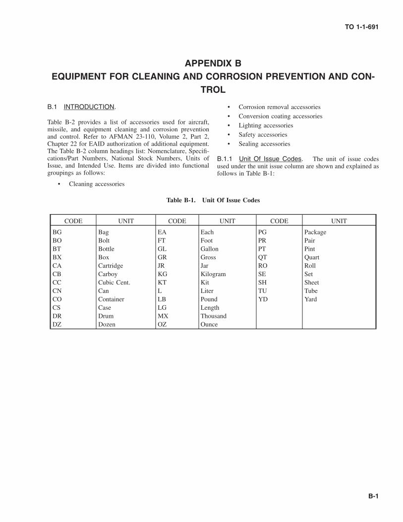
APPENDIX BEQUIPMENT FOR CLEANING AND CORROSION PREVENTION AND CON-
TROL
B.1 INTRODUCTION.
Table B-2 provides a list of accessories used for aircraft,missile, and equipment cleaning and corrosion preventionand control. Refer to AFMAN 23-110, Volume 2, Part 2,Chapter 22 for EAID authorization of additional equipment.The Table B-2 column headings list: Nomenclature, Specifi-cations/Part Numbers, National Stock Numbers, Units ofIssue, and Intended Use. Items are divided into functionalgroupings as follows:
• Cleaning accessories
• Corrosion removal accessories
• Conversion coating accessories
• Lighting accessories
• Safety accessories
• Sealing accessories
B.1.1 Unit Of Issue Codes. The unit of issue codesused under the unit issue column are shown and explained asfollows in Table B-1:
Table B-1. Unit Of Issue Codes
CODE UNIT CODE UNIT CODE UNIT
BG Bag EA Each PG PackageBO Bolt FT Foot PR PairBT Bottle GL Gallon PT PintBX Box GR Gross QT QuartCA Cartridge JR Jar RO RollCB Carboy KG Kilogram SE SetCC Cubic Cent. KT Kit SH SheetCN Can L Liter TU TubeCO Container LB Pound YD YardCS Case LG LengthDR Drum MX ThousandDZ Dozen OZ Ounce
TO 1-1-691
B-1

Tabl
eB
-2.
Equ
ipm
ent
For
Cle
anin
gan
dC
orro
sion
Pre
vent
ion
and
Con
trol
Item No.
Nom
encl
atur
eSp
ecifi
catio
ns/P
art
Num
ber
Nat
iona
lSt
ock
Num
ber
Uni
tIs
sue
Inte
nded
Use
Cle
anin
gE
quip
men
t1
Air
craf
tW
ashi
ngK
it,E
xter
ior,
Con
form
-ab
le
3MC
o.(C
AG
EC
ode
#763
81)
Gen
eral
clea
ning
ofai
rcra
ft,
mis
sile
,an
deq
uipm
ent
surf
aces
.U
ses
12in
Lx
6in
Wx
1in
orus
ere
plac
emen
tpa
dslis
ted
asIt
em#
38in
App
endi
xA
.PN
251
(Con
form
able
appl
ica-
tor
head
&2
EA
ofea
chty
peof
pad)
7920
-00-
490-
6046
KT
2Sp
onge
,Sy
nthe
ticL
-S-6
26,
Cla
ss1,
Gra
deB
orA
-A-2
073,
Type
I,St
yle
B,
Cla
ss1
7920
-00-
633-
9915
EA
(7in
Lx
4¼in
Wx
23⁄8
inT
)
Fine
pore
synt
hetic
spon
gefo
rap
plic
atio
nof
clea
n-in
gco
mpo
unds
onan
dsc
rubb
ing
ofpa
inte
dan
dun
pain
ted
surf
aces
byha
nd.
3Sc
rub
Bru
shA
-A-2
074
(sup
erse
des
H-B
-14
90)
App
licat
ion
ofcl
eani
ngco
mpo
unds
and
scru
bbin
gof
pain
ted
and
unpa
inte
dai
rcra
ft,
mis
sile
and
equi
pmen
tsu
rfac
es.
Type
I,St
yle
A(N
ylon
Bri
stle
s)79
20-0
0-61
9-91
62E
A(4
½in
x1¾
in)
Type
II,
Styl
eC
(Tam
pico
Bri
stle
s)79
20-0
0-28
2-24
70E
A(1
0¾in
x2¾
in)
Type
IV,
Styl
eB
(Nyl
onB
rist
les)
7920
-00-
061-
0037
EA
(8½
inx
5in
)Ty
peIV
,St
yle
D(P
alm
yra
Bri
stle
s)79
20-0
1-06
7-62
03E
A(8
½in
D)
TO 1-1-691
B-2 Change 1

Tabl
eB
-2.
Equ
ipm
ent
For
Cle
anin
gan
dC
orro
sion
Pre
vent
ion
and
Con
trol
-C
onti
nued
Item No.
Nom
encl
atur
eSp
ecifi
catio
ns/P
art
Num
ber
Nat
iona
lSt
ock
Num
ber
Uni
tIs
sue
Inte
nded
Use
4B
rush
,Air
craf
tC
lean
-in
gM
IL-B
-239
58Ty
peI
(Nyl
onB
rist
les)
App
licat
ion
ofcl
eani
ngco
mpo
unds
and
scru
bbin
gof
pain
ted
and
unpa
inte
dai
rcra
ft,
mis
sile
and
equi
pmen
tsu
rfac
es.
Styl
e1
7920
-00-
054-
7768
EA
(53⁄8
inD
)St
yle
279
20-0
0-05
1-43
86E
A(6
inx
2in
)St
yle
379
20-0
0-05
1-43
83E
A(1
2in
x3½
in)
Type
II(T
ampi
coB
rist
les)
Styl
e2
7920
-00-
957-
5945
EA
(6in
x2½
in)
Type
III
(Nyl
on/
Tam
pico
Bri
stle
s)St
yle
179
20-0
0-05
1-43
84E
A(5
3⁄8
inD
)St
yle
279
20-0
0-05
1-43
87E
A(6
inx
2in
)St
yle
379
20-0
0-05
1-43
85E
A(1
2in
x3½
in)
Type
IV(H
orse
hair
/Syn
-the
ticB
rist
les)
Styl
e4
7920
-00-
685-
5969
EA
(10
inx
2¾in
)5
Win
dow
Bru
sh,
Wat
er-
proo
f(H
orse
hair
Bri
stle
s)
Type
I(R
ound
)Sc
rubb
ing
airc
raft
,m
issi
le,
and
equi
pmen
tpa
inte
dan
dun
pain
ted
surf
aces
,w
indo
ws,
win
dshi
elds
,an
d/or
win
dscr
eens
.79
20-0
0-24
0-71
76E
A(4
.5in
D)
7920
-00-
297-
1509
EA
(8in
D)
Type
II(R
ecta
ngul
ar)
7920
-01-
136-
8892
EA
(6in
x4
in)
6To
othb
rush
,So
ftB
rist
le,
Stra
ight
Lin
eD
esig
n.
A-A
-59
(Chi
ldre
n’s
-30
Tuf
ts)
8530
-01-
293-
1388
DZ
Cle
anin
gin
tric
ate
part
s.B
efor
eus
ing,
ensu
rech
emi-
cals
will
not
diss
olve
orso
ften
brus
hha
ndle
and
bris
tles.
A-A
-123
(Adu
lt’s
-30
Tuf
ts)
8530
-01-
293-
1387
DZ
TO 1-1-691
Change 1 B-3

Tabl
eB
-2.
Equ
ipm
ent
For
Cle
anin
gan
dC
orro
sion
Pre
vent
ion
and
Con
trol
-C
onti
nued
Item No.
Nom
encl
atur
eSp
ecifi
catio
ns/P
art
Num
ber
Nat
iona
lSt
ock
Num
ber
Uni
tIs
sue
Inte
nded
Use
7H
andl
es,
Woo
d,A
cme
Thr
eade
dan
dTa
-pe
red
End
s
A-A
-308
2(s
uper
sede
sN
N-H
-10
4)H
andl
esfo
rus
ew
ithsc
rub/
clea
ning
brus
hes
(Ite
ms
3&
4)an
dai
rcra
ftw
ashi
ngki
t(I
tem
1).
Type
I(T
hrea
ded
met
alen
d)7/ 8
inD
x4
ftL
7920
-00-
982-
6512
EA
Type
II(T
aper
eden
d)15
/16
inD
x4½
L79
20-0
0-17
7-51
06E
A15
/16
inD
x5
ftL
7920
-00-
263-
0328
EA
1in
Dx
4½L
7920
-00-
141-
5452
EA
1in
Dx
8ft
L79
20-0
0-26
3-03
27E
A1
inD
x4¼
ftL
7920
-00-
263-
0324
EA
8H
andl
e,A
cme
Thr
eade
dE
nd(T
ele-
scop
ic)
A-A
-146
4(7
/ 8in
D)
7920
-00-
926-
5146
EA
A5
ftto
10ft
exte
ndab
leal
umin
umha
ndle
for
scru
b/cl
eani
ngbr
ushe
s(I
tem
s3
&4)
orai
rcra
ftw
ashi
ngki
t(I
tem
1)to
clea
nhi
ghsu
rfac
eson
airc
raft
oreq
uipm
ent.
9N
ozzl
es,
Gar
den
Hos
e(F
or5/ 8
and
¾in
Hos
e)A
djus
tabl
e
A-A
-504
61Sp
rayi
ngan
dri
nsin
gof
airc
raft
,m
issi
les,
and
equi
p-m
ent
duri
ngcl
eani
ngop
erat
ions
.St
raig
ht,A
djus
tabl
eSp
ray
(Bra
ss)
4730
-00-
223-
6731
EA
Pist
olG
rip,
Adj
usta
ble
(Cop
-pe
rA
lloy
w/R
ubbe
rC
over
)PN
1085
5;C
AG
EC
ode
#97
141
4730
-00-
900-
0733
EA
10H
ose
and
Hos
eA
ssem
-bl
ies,
Non
-Met
allic
(Rub
ber,
Plas
tic)
A-A
-592
70(s
uper
sede
sL
-H-
520)
Spra
ying
and
rins
ing
ofai
rcra
ft,
mis
sile
s,an
deq
uip-
men
tdu
ring
clea
ning
oper
atio
ns.
Type
I,C
lass
I(R
ubbe
r)5/ 8
inID
x50
ftL
4720
-00-
203-
3920
EA
¾in
IDx
50ft
L47
20-0
0-20
3-39
12E
ATy
peII
,G
rade
A(P
VC
)5/ 8
inx
50ft
4720
-00-
729-
5334
EA
¾in
x50
ft47
20-0
0-72
9-53
38E
A11
Pum
p,B
ackp
ack
PN:
5100
-254
B43
20-0
0-28
9-89
12E
AL
ocal
ized
smal
lar
eacl
eani
ngan
dri
nsin
gof
air-
craf
t,m
issi
le,
and
equi
pmen
tsu
rfac
es.
(5G
Lca
paci
ty)
CA
GE
Cod
e#
0402
412
Spra
yers
Inse
ctic
ide,
Man
ually
-Car
ried
,H
and
Ope
rate
d-C
ompr
essi
on
A-A
-557
4837
40-0
0-19
1-36
77E
A(1
GL
ca-
paci
ty)
Use
dto
appl
yso
ilba
rrie
rm
ater
ial
onai
rcra
ftsu
r-fa
ces
(sup
erse
des
MIL
-S-1
4102
)37
40-0
0-64
1-47
19E
A(2
GL
ca-
paci
ty)
TO 1-1-691
B-4

Tabl
eB
-2.
Equ
ipm
ent
For
Cle
anin
gan
dC
orro
sion
Pre
vent
ion
and
Con
trol
-C
onti
nued
Item No.
Nom
encl
atur
eSp
ecifi
catio
ns/P
art
Num
ber
Nat
iona
lSt
ock
Num
ber
Uni
tIs
sue
Inte
nded
Use
13G
uns,
Spra
y,O
ilsan
dSo
lven
tSA
EA
MS-
G-9
52(s
uper
sede
sM
IL-G
-952
)Ty
peI
4940
-00-
248-
0866
EA
Non
-ato
miz
ing,
trig
ger
oper
ated
spra
yno
zzle
for
spra
ying
clea
ning
com
poun
dson
airc
raft
,m
issi
les,
and
equi
pmen
t.14
Cle
anin
gU
nit,
Por-
tabl
e,Fo
amG
ener
at-
ing
Stai
nles
sSt
eel
Tank
(Por
ta-F
oam
er)
PN00
20SS
CA
GE
Cod
e#
2136
149
40-0
1-05
8-52
67E
A(1
5G
Lca
paci
ty)
Foam
appl
icat
orfo
rM
IL-P
RF-
8793
7an
dM
IL-P
RF-
8557
0cl
eani
ngco
mpo
unds
for
clea
ning
airc
raft
,m
issi
le,
and
equi
pmen
tex
teri
ors.
Use
sco
m-
pres
sed
air
tosp
ray
wat
erde
terg
ent
solu
tions
.M
ayal
sobe
used
toap
ply
clea
ning
solv
ents
for
clea
ning
engi
nes
and
othe
req
uipm
ent.
Agu
nty
pesp
ray
wan
dan
dno
zzle
isin
clud
ed.
PN94
88-7
023
CA
GE
Cod
e#
8588
449
40-0
1-04
1-56
80E
A(4
5G
Lca
paci
ty)
15C
lean
er,
Pres
sure
,So
lven
t-W
ater
(Uni
-ve
rsal
Was
hU
nit)
PN21
C24
38G
01C
AG
EC
ode
#99
207
4940
-01-
185-
6215
EA
Use
dto
appl
ycl
eani
ngco
mpo
und
solu
tions
ina
non-
foam
stat
eto
airc
raft
,m
issi
le,
and
equi
pmen
tex
teri
orsu
rfac
esat
ara
teof
2½G
L/
min
.at
30PS
Ipr
essu
re.
16C
art,
Cor
rosi
onC
ontr
ol(T
urbi
neE
ngin
eC
lean
ing)
Mod
el#
6255
5PN
65A
102J
1C
AG
EC
ode
#0G
ZN
849
20-0
0-93
0-18
01E
APo
rtab
lecl
eani
ngm
achi
nefo
rcl
eani
ngan
dri
nsin
gai
rcra
fttu
rbin
een
gine
s.
17D
eice
r,A
ircr
aft
(Tru
ckM
ount
ed)
Mod
el#
5832
3PN
D40
-DC
AG
EC
ode
#’s
5832
3&
9340
8
1730
-01-
093-
6517
EA
Tru
ckm
ount
edsp
ray
unit
used
tosp
ray
deic
ing
and
anti-
icin
gflu
ids
onai
rcra
ftex
teri
orsu
rfac
es.
18H
eate
r,G
un,
Ele
ctri
cTy
peA
-A-5
9435
Toth
awor
dry
equi
pmen
t/com
pone
nts
orto
shri
nkhe
atsh
rink
type
insu
latin
gtu
bing
asso
ciat
edw
ithel
ectr
ical
appl
icat
ions
.Ty
peI
(350
°-5
00°
F)49
40-0
0-35
7-13
69E
ATy
peII
(500
°-7
50°
F)49
40-0
1-02
8-74
93E
ATy
peII
I(7
50°-
1000
°F)
4940
-01-
391-
7046
EA
19V
acuu
mC
lean
er,
Pneu
-m
atic
PNA
T56
0AC
F-18
CA
GE
Cod
e#
0078
451
30-0
1-36
8-58
61E
ASm
all,
light
-wei
ght,
alum
inum
,ve
ntur
ity
pe,
hand
held
vacu
umcl
eane
rw
ith18
inL
flexi
ble
hose
for
rem
ovin
gdi
rtan
dde
bris
from
airc
raft
,m
is-
sile
,an
deq
uipm
ent
inte
rior
s.20
Vac
uum
Cle
aner
(with
atta
chm
ents
)Pn
eum
atic
Type
PN15
-A10
80C
AG
EC
ode
#58
150
7910
-00-
807-
3704
EA
For
rem
ovin
gdi
rt,
debr
is,
and
fluid
sfr
omai
rcra
ft,
mis
sile
,an
deq
uipm
ent
inte
rior
s.E
lect
ric
Type
(A-A
-549
43)
PNC
8398
5-01
CA
GE
Cod
e#
1689
3
7910
-01-
236-
0893
EA
For
rem
ovin
gdi
rt,
debr
is,
and
fluid
sfr
omai
rcra
ft,
mis
sile
,an
deq
uipm
ent
inte
rior
s.T
his
vacu
umcl
eane
rca
nal
sobe
used
tore
mov
ein
fect
ious
was
tem
ater
ials
.
TO 1-1-691
B-5

Tabl
eB
-2.
Equ
ipm
ent
For
Cle
anin
gan
dC
orro
sion
Pre
vent
ion
and
Con
trol
-C
onti
nued
Item No.
Nom
encl
atur
eSp
ecifi
catio
ns/P
art
Num
ber
Nat
iona
lSt
ock
Num
ber
Uni
tIs
sue
Inte
nded
Use
21B
ottle
,App
licat
or,
16O
ZC
apac
ity(A
d-ju
stab
leSp
ray
Noz
zle)
A-A
-280
681
25-0
0-48
8-79
52E
ASp
rayi
ngof
clea
ning
com
poun
dso
lutio
nson
smal
lar
eas
ofai
rcra
ft,
mis
sile
,an
deq
uipm
ent
surf
aces
.
22Sp
ray
Kit,
Self
Pres
sur-
ized
Tri
gger
Spra
y,Po
ly-e
thyl
ene
Bot
tle(3
2O
ZC
apac
ity)
PN43
82T
1C
AG
EC
ode
#39
428
4940
-01-
364-
8761
EA
Spra
ying
ofcl
eani
ngco
mpo
und
solu
tions
onsm
all
area
sof
airc
raft
,m
issi
le,
and
equi
pmen
tsu
rfac
es
23U
tility
Pail,
Plas
tic(3
GL
Cap
acity
)A
-A-5
9253
(sup
erse
des
L-P
-65
)Si
ze4;
Styl
eB
7240
-00-
246-
1097
EA
Con
tain
erfo
rho
ldin
gw
ater
and
chem
ical
solu
tions
for
clea
ning
and
corr
osio
ntr
eatm
ent
oper
atio
ns.
Con
vers
ion
Coa
ting
Equ
ipm
ent
24B
rush
,Aci
dSw
abbi
ng(M
etal
Han
dle/
Hor
seha
ir&
Hog
Bri
stle
Bru
sh)
A-A
-289
,Ty
peII
,C
lass
1,Si
ze1
7920
-00-
514-
2417
GR
(5¾
inL
x3⁄8
inW
)D
ispo
sabl
ebr
ush
for
appl
ying
chem
ical
conv
ersi
onco
atin
gso
lutio
nsan
dso
me
brus
habl
ese
alan
ts.
25M
oist
ener
,Pa
per
Seal
-in
g,Fo
unta
in-T
ype
(Spo
nge
Moi
sten
erSt
ick)
A-A
-137
(sup
erse
des
GG
-M-
571)
7520
-00-
241-
2981
EA
App
licat
ion
ofch
emic
alco
nver
sion
coat
ing
solu
-tio
nsto
smal
lar
eas.
26W
ash
Bot
tle,
Lab
ora-
tory
,Po
lyet
hyle
ne(2
50m
l.C
apac
ity)
Com
mer
cial
Item
CA
GE
Cod
e#
2551
866
40-0
0-29
9-84
93E
AB
X(1
2E
A)
Use
dfo
rri
nsin
gch
emic
ally
trea
ted
surf
aces
.
Cor
rosi
onR
emov
alE
quip
men
t27
Dri
ll,Pn
eum
atic
,Po
r-ta
ble
(¼in
Chu
ck;
3200
RPM
)
OO
-D-6
91C
orro
sion
rem
oval
and
scuf
fsa
ndin
g.
Type
I,St
yle
C(S
trai
ght
Dri
ve,
Pist
olG
rip)
5130
-00-
294-
9511
EA
Type
I,St
yle
A(9
0°A
ngle
Dri
ve,
Bod
yG
rip)
5130
-00-
293-
1977
EA
28K
ey,
Dri
llC
huck
(¼in
Dri
ve)
A-A
-509
66PN
K1
CA
GE
Cod
e#
7507
834
60-0
0-26
4-55
77E
ASe
curi
ngor
rele
asin
gdr
illbi
t.Fo
rus
ew
ithIt
em#
27dr
illm
otor
.29
Sand
er,
Pad,
Pneu
mat
ic(O
rbita
lM
otio
n)6,
000
-9,
000
RPM
A-A
-268
7(O
O-S
-101
,Ty
peI,
Styl
e1)
5130
-00-
606-
9694
EA
Cor
rosi
onre
mov
alan
dbl
end
out
asw
ell
assc
uff
sand
ing,
finis
hsa
ndin
g,an
dfe
athe
red
ging
/ble
nd-
ing
ofpa
int
surf
aces
.
TO 1-1-691
B-6 Change 1

Tabl
eB
-2.
Equ
ipm
ent
For
Cle
anin
gan
dC
orro
sion
Pre
vent
ion
and
Con
trol
-C
onti
nued
Item No.
Nom
encl
atur
eSp
ecifi
catio
ns/P
art
Num
ber
Nat
iona
lSt
ock
Num
ber
Uni
tIs
sue
Inte
nded
Use
30Sa
nder
,D
isc,
Pneu
-m
atic
,Po
rtab
le(R
an-
dom
Orb
ital)
A-A
-269
0(O
O-S
-101
,Ty
peII
,St
yle
3)51
30-0
0-20
4-06
23E
AC
orro
sion
rem
oval
and
blen
dou
tas
wel
las
scuf
fsa
ndin
g,fin
ish
sand
ing,
and
feat
her
edgi
ng/b
lend
-in
gof
pain
tsu
rfac
es.
The
sand
er’s
rand
omor
bita
lac
tion
prev
ents
scra
tche
san
dsw
irl
mar
ks.
Dua
lm
otio
n,ve
rtic
aldr
ive
with
6in
Dm
axpa
d&
7000
RPM
max
(unl
oade
d)31
Sand
er,
Dis
c,Pn
eu-
mat
ic,
Port
able
(Rig
htA
ngle
)R
ight
angl
edr
ive
with
7in
Dpa
dm
ax&
6000
RPM
max
(unl
oade
d)
A-A
-268
9(O
O-S
-101
,Ty
peII
,St
yle
2)51
30-0
0-59
6-11
76E
AC
orro
sion
rem
oval
and
blen
dou
t.R
ight
angl
edr
ive
mak
esit
easi
erto
use
inco
rner
s,al
ong
edge
s,an
din
tight
spac
es.
32D
ryH
onin
gM
achi
ne,
Port
able
,Air
-O
pera
ted
(Vac
u-B
last
er)
PN41
303
CA
GE
Cod
e#
6255
549
40-0
0-87
2-17
12E
AA
com
pact
,se
lf-c
onta
ined
,lig
htw
eigh
tab
rasi
vebl
astin
gun
itus
edfo
rth
esa
fean
dco
nven
ient
re-
mov
alof
corr
osio
npr
oduc
tsfr
omai
rcra
ft,
mis
sile
and
equi
pmen
tsu
rfac
esan
dth
eir
com
pone
nts
with
noha
zard
ous
part
icle
emis
sion
s.A
llab
rasi
vepa
rtic
les,
corr
osio
npr
oduc
ts,
and
pain
tch
ips
are
draw
nba
ckin
toth
em
achi
new
here
resi
dues
are
filte
red
out
and
colle
cted
for
disp
osal
,an
dth
eab
rasi
vepa
rtic
les
are
recy
cled
.33
Ele
ctri
cal
Pum
pK
itfo
rD
ryH
onin
gM
achi
ne(I
tem
#32
)
PN91
8708
CA
GE
Cod
e#
6255
549
40-0
0-94
8-38
10E
AT
heel
ectr
icpu
mp
for
the
Dry
Hon
ing
Mac
hine
al-
low
sus
eof
low
pres
sure
/low
volu
me
air
toop
er-
ate
inst
ead
ofth
elo
wpr
essu
re/h
igh
volu
me
air
requ
ired
toop
erat
eun
itseq
uipp
edw
ithth
eai
rej
ecto
rpu
mp.
34G
un,A
irB
low
,(B
last
Cle
anin
g)A
-A-5
5543
(sup
erse
des
GG
G-
G-7
70)
Use
tore
mov
ech
ips,
dirt
,an
dw
aste
mat
eria
lfr
omm
achi
nes,
wor
kpi
eces
,or
benc
hes.
Type
II(p
ush
butto
n),
Styl
eB
(3⁄8
inIn
t.T
hd.)
4940
-00-
223-
8972
EA
Type
II(p
ush
butto
n),
Styl
eA
(¼in
Int.
Thd
.)49
40-0
0-33
3-55
41E
A
TO 1-1-691
Change 1 B-7

Tabl
eB
-2.
Equ
ipm
ent
For
Cle
anin
gan
dC
orro
sion
Pre
vent
ion
and
Con
trol
-C
onti
nued
Item No.
Nom
encl
atur
eSp
ecifi
catio
ns/P
art
Num
ber
Nat
iona
lSt
ock
Num
ber
Uni
tIs
sue
Inte
nded
Use
35A
irH
ose
Ass
embl
ies,
Gen
eral
Purp
ose
Hos
ean
dH
ose
As-
sem
blie
s,N
on-
Met
allic
Spra
y
A-A
-596
13H
ose
asse
mbl
ies
used
with
pneu
mat
icto
ols,
pain
tsp
ray
guns
,an
ddr
yho
ning
mac
hine
s.
3⁄8
inID
x50
ft47
20-0
0-28
9-34
29FT
Hos
e,R
ubbe
r,an
dH
ose
Ass
embl
ies,
Rub
ber,
Pneu
mat
ic(Y
arn
and
Fabr
icR
einf
orce
d)
A-A
-595
65
½in
IDx
50ft
4720
-00-
278-
4889
FT5/ 8
inID
x50
ft47
20-0
0-27
8-48
90FT
¾in
IDx
50ft
4720
-00-
278-
4891
FT
36C
oupl
ing
Hal
ves,
Qui
ck-D
isco
nnec
tA
-A-5
9439
(sup
erse
desM
IL-
C-4
109)
Type
II(M
ale)
¼in
NPT
/Men
d(S
tyle
1)47
30-0
0-49
4-32
71E
AM
ale
quic
kdi
scon
nect
halv
esfo
rus
ew
ithpn
eu-
mat
icto
ols
and
pain
tsp
ray
guns
.3⁄8
inN
PT/F
end
(Sty
le2)
4730
-00-
293-
7182
EA
3⁄8
inSh
ank
end
(Sty
le3)
4730
-00-
277-
5679
EA
½in
NPT
/Men
d(S
tyle
1)47
30-0
0-29
3-71
65E
AM
ale
quic
kdi
scon
nect
halv
esfo
rus
ew
ithpo
rtab
ledr
yho
ning
mac
hine
s.½
inN
PT/F
end
(Sty
le2)
4730
-01-
233-
3434
EA
¾in
NPT
/Men
d(S
tyle
1)47
30-0
0-29
3-71
80E
ATy
peI
(Fem
ale)
¼in
NPT
/Fen
d(S
tyle
2)47
30-0
1-17
7-09
87E
AFe
mal
equ
ick
disc
onne
ctha
lves
for
use
with
pneu
-m
atic
tool
san
dpa
int
spra
ygu
ns.
3⁄8
inN
PT/M
end
(Sty
le1)
4730
-00-
203-
0178
EA
3⁄8
inSh
ank
end
(Sty
le3)
4730
-00-
494-
3272
EA
½in
NPT
/Men
d(s
tyle
1)47
30-0
0-20
3-48
47E
AFe
mal
equ
ick
disc
onne
ctha
lves
for
use
with
por-
tabl
edr
yho
ning
mac
hine
s.½
inSh
ank
end
(Sty
le3)
4730
-00-
905-
9794
EA
¾in
NPT
/Men
d(S
tyle
1)47
30-0
0-29
3-70
43E
A37
Hos
eC
lam
pA
-A-5
2506
(sup
erse
des
WW
-C
-440
)47
30-0
0-82
6-42
68E
AM
etal
hose
clam
pus
edfo
rho
ldin
gfle
xibl
edu
cts
orho
ses
onto
am
ale
end
ora
38H
and
Pad
Hol
der
(for
use
with
Item
#1,
App
endi
xA
)
3MC
o.PN
952
(IN
STA
-L
OK
)C
AG
EC
ode
#28
124
Com
mer
cial
Item
Ope
nPu
rcha
seE
AH
and
tool
for
hold
ing
abra
sive
pads
.
TO 1-1-691
B-8 Change 1

Tabl
eB
-2.
Equ
ipm
ent
For
Cle
anin
gan
dC
orro
sion
Pre
vent
ion
and
Con
trol
-C
onti
nued
Item No.
Nom
encl
atur
eSp
ecifi
catio
ns/P
art
Num
ber
Nat
iona
lSt
ock
Num
ber
Uni
tIs
sue
Inte
nded
Use
39H
olde
r,D
isk
Pad,
Hoo
kan
dL
oop
Type
(for
use
with
Item
#47
)
3MC
o.(C
AG
EC
ode
#28
124)
Bac
k-up
pad
toru
nsu
rfac
eco
nditi
onin
gdi
scs
ona
drill
mot
or.
PN92
15C
omm
erci
alIt
emE
A(1
½in
Don
¼in
shan
k)O
pen
Purc
hase
PN04
8011
-074
94-8
Com
mer
cial
Item
CS
(10
EA
)(2
inD
on¼
insh
ank)
Ope
nPu
rcha
sePN
923
(3in
Don
¼in
shan
k)53
45-0
1-34
2-59
32E
APN
0480
11-0
7492
-4C
omm
erci
alIt
emC
S(5
EA
)(4
inD
on¼
insh
ank)
Ope
nPu
rcha
sePN
0480
11-0
5680
-7C
omm
erci
alIt
emE
A(5
inD
on¼
insh
ank)
Ope
nPu
rcha
se40
Pad,
Abr
asiv
eD
isk
Hol
der
(for
use
with
Item
#5,
App
endi
x.A
)
3MC
o.(C
AG
EC
ode
#28
124)
Bac
k-up
pad
toru
n6
inD
abra
sive
pape
rdi
scs
ona
dual
mot
ion
type
sand
er.
PN05
1144
-055
7651
30-0
1-07
5-81
37E
A
41M
andr
els
(for
use
with
Item
#’s
42an
d43
)3M
Co.
(CA
GE
Cod
e#
2812
4)PN
990
(3⁄8
insh
ank)
Ope
nPu
rcha
seB
X(5
EA
)Fo
rus
ew
ith2
-3
inD
radi
albr
istle
disc
sst
acke
dfr
om1⁄8
to½
inW
PN99
1(3
⁄8in
shan
k)O
pen
Purc
hase
BX
(5E
A)
For
use
with
2-
3in
Dra
dial
bris
tledi
scs
stac
ked
from
¾in
to1
inW
PN93
334
60-0
1-04
4-26
26E
AFo
rus
ew
ith2
to3
inD
abra
sive
disc
s.(2
inL
;¼
insh
ank
w/1
inD
was
her)
PN93
4,34
60-0
0-15
0-71
64E
AFo
rus
ew
ith3
to6
inD
abra
sive
disc
s.(3
1/16
inL
;¼
insh
ank
w/
2½in
Dw
ashe
r)PN
935,
Split
Min
iM
andr
el34
60-0
0-15
0-71
63E
AFo
rus
ew
ith1
inW
x1½
inL
piec
esof
abra
sive
mat
eria
lto
fitin
totig
htar
eas
for
corr
osio
nre
-m
oval
.(2
inL
;¼
insh
ank)
TO 1-1-691
Change 1 B-9

Tabl
eB
-2.
Equ
ipm
ent
For
Cle
anin
gan
dC
orro
sion
Pre
vent
ion
and
Con
trol
-C
onti
nued
Item No.
Nom
encl
atur
eSp
ecifi
catio
ns/P
art
Num
ber
Nat
iona
lSt
ock
Num
ber
Uni
tIs
sue
Inte
nded
Use
42R
oloc
TM
Dis
cPa
dH
olde
rsfo
rIn
Lin
eB
rist
leD
iscs
(Ite
m#
45)
and
Rol
ocT
M-
Coa
ted
Abr
asiv
eD
iscs
(Ite
m#
46)
3MC
o.(C
AG
EC
ode
#28
124)
Com
mer
cial
Item
sU
sed
toho
ldR
oloc
TM
in-l
ine
bris
tledi
scs
and
coat
edab
rasi
vedi
scs
for
inst
alla
tion
onei
ther
inlin
eor
righ
tan
gle
drill
mot
ors.
PN05
1144
-451
01O
pen
Purc
hase
BX
(5E
A)
(1in
DH
olde
r)PN
0511
44-4
5095
-4O
pen
Purc
hase
BX
(5E
A)
(2in
DH
olde
r)PN
0511
44-4
5092
-3O
pen
Purc
hase
BX
(5E
A)
(3in
DH
olde
r)PN
0511
44-4
5179
-1O
pen
Purc
hase
BX
(5E
A)
(4in
DH
olde
r)PN
0511
44-4
5102
-9O
pen
Purc
hase
EA
(¼in
Dth
read
edsh
aft)
43W
heel
,Fl
apB
rush
,A
bras
ive
(Non
-w
oven
nylo
nfla
psw
ithal
umin
umox
ide
abra
sive
;M
aroo
nin
colo
r)(6
inD
x1
inW
x2
inar
bor
hole
)
3MC
o.(C
AG
EC
ode
#28
124)
Com
mer
cial
Item
sR
emov
ing
mild
corr
osio
nfr
oman
dpo
lishi
ngof
surf
aces
.Als
ofo
rm
echa
nica
lre
mov
alan
dfe
ath-
erin
gof
pain
tsy
stem
s.M
axim
umop
erat
ing
spee
d(M
OS)
is34
00R
PM.
Use
don
PN93
4m
andr
el(I
tem
#41
abov
e).
PN5A
FN6X
1X2
(fine
grit)
5345
-00-
151-
7936
EA
PN5A
MD
6X1X
2(m
ediu
mgr
it)53
45-0
0-15
7-97
90E
A
TO 1-1-691
B-10

Tabl
eB
-2.
Equ
ipm
ent
For
Cle
anin
gan
dC
orro
sion
Pre
vent
ion
and
Con
trol
-C
onti
nued
Item No.
Nom
encl
atur
eSp
ecifi
catio
ns/P
art
Num
ber
Nat
iona
lSt
ock
Num
ber
Uni
tIs
sue
Inte
nded
Use
44St
acka
ble
Rad
ial
Bri
stle
Dis
cs,
(Re-
galit
eTM
/Alu
min
umO
xide
&C
ubitr
onA
bras
ive)
3MC
o.(C
AG
EC
ode
#28
124)
Com
mer
cial
Item
sR
emov
ing
mild
corr
osio
nan
dpo
lishi
ngsu
rfac
esan
dde
-bur
ring
.Als
ofo
rm
echa
nica
lre
mov
alof
cure
dse
alan
ts,
adhe
sive
s,pa
ints
,an
dfe
athe
ring
ofpa
int
syst
ems.
Use
with
adr
illan
da
#93
4,99
0,or
991
man
drel
asap
prop
riat
e.C
anbe
used
tore
ach
into
deep
depr
esss
ions
and
cavi
ties.
Can
beus
edon
in-l
ine
orri
ght
angl
edr
illm
otor
s.T
heM
OS
is25
,000
RPM
.
3in
D-
Man
drel
Mou
nted
PN04
8011
-242
79-8
(Gra
de50
-G
reen
Col
or)
Ope
nPu
rcha
seC
S(4
0E
A)
PN04
8011
-242
80-4
Ope
nPu
rcha
seC
S(4
0E
A)
(Gra
de80
-Y
ello
wC
olor
)PN
0480
11-2
4281
-1(G
rade
120
-W
hite
Col
or)
Ope
nPu
rcha
seC
S(4
0E
A)
PN05
1131
-075
44-3
3460
-01-
509-
1789
CS
(40
EA
)(G
rade
120
-W
hite
Col
or;
Thi
ckB
rist
les)
Rol
ocT
MD
isc
Pad
Hol
der
Mou
nted
PN04
8011
-242
76-7
(Gra
de50
-G
reen
Col
or)
Ope
nPu
rcha
seS
(40
EA
)
PN04
8011
-242
77-4
(Gra
de80
-Y
ello
wC
olor
)O
pen
Purc
hase
CS
(40
EA
)
PN04
8011
-242
78-1
(Gra
de12
0-
Whi
teC
olor
)O
pen
Purc
hase
CS
(40
EA
)
Rol
ocT
MD
isc
Pad
Hol
der
for
thes
eR
adia
lB
rist
leD
iscs
PN05
1144
-451
01-2
Ope
nPu
rcha
seB
X(5
EA
)
TO 1-1-691
B-11

Tabl
eB
-2.
Equ
ipm
ent
For
Cle
anin
gan
dC
orro
sion
Pre
vent
ion
and
Con
trol
-C
onti
nued
Item No.
Nom
encl
atur
eSp
ecifi
catio
ns/P
art
Num
ber
Nat
iona
lSt
ock
Num
ber
Uni
tIs
sue
Inte
nded
Use
45R
oloc
TM
InL
ine
Bri
stle
Dis
cs3M
Co.
(CA
GE
Cod
e#
2812
4)C
omm
erci
alIt
ems
Rem
ovin
gm
ildco
rros
ion
and
polis
hing
surf
aces
and
de-b
urri
ng.A
lso
for
mec
hani
cal
rem
oval
ofcu
red
seal
ants
,ad
hesi
ves,
and
pain
tsan
dfe
athe
r-in
gof
pain
tsy
stem
s.C
anbe
used
onin
line
orri
ght
angl
edr
illm
otor
saf
ter
mou
ntin
gon
anap
-pr
opri
ate
Rol
ocT
Mdi
scpa
dho
lder
(Ite
m#
42)
The
max
imum
oper
atin
gsp
eed
(MO
S)de
pend
son
the
diam
eter
ofth
edi
sc.
(Reg
alite
Rol
ocT
M/A
lu-
min
umO
xide
&C
u-bi
tron
Abr
asiv
e)
1in
Dw
/5/ 8
inL
bris
tles
PN04
8011
-186
98-6
Ope
nPu
rcha
seC
S(8
0E
A)
(Gra
de50
-G
reen
Col
or)
PN04
8011
-187
06-8
Ope
nPu
rcha
seC
S(8
0E
A)
(Gra
de80
-Y
ello
wC
olor
)PN
0480
11-1
8710
-5O
pen
Purc
hase
CS
(40
EA
)(G
rade
120
-W
hite
Col
or)
2in
Dw
/5/ 8
inL
bris
tles
PN04
8011
-187
30-3
Ope
nPu
rcha
seC
S(4
0E
A)
(Gra
de50
-G
reen
Col
or)
PN04
8011
-187
32-7
5345
-01-
432-
3032
CS
(40
EA
)(G
rade
80-
Yel
low
Col
or)
PN04
8011
-187
33-4
3460
-01-
509-
1806
(Gra
de12
0-
Whi
teC
olor
)3
inD
w/
5/ 8
inL
bris
tles
PN04
8011
-187
34-1
Ope
nPu
rcha
seC
S(4
0E
A)
(Gra
de50
-G
reen
Col
or)
PN04
8011
-187
36-5
Ope
nPu
rcha
seC
S(4
0E
A)
(Gra
de80
-Y
ello
wC
olor
)PN
0480
11-1
8737
-234
60-0
1-50
9-18
29C
S(4
0E
A)
(Gra
de12
0-
Whi
teC
olor
)
TO 1-1-691
B-12

Tabl
eB
-2.
Equ
ipm
ent
For
Cle
anin
gan
dC
orro
sion
Pre
vent
ion
and
Con
trol
-C
onti
nued
Item No.
Nom
encl
atur
eSp
ecifi
catio
ns/P
art
Num
ber
Nat
iona
lSt
ock
Num
ber
Uni
tIs
sue
Inte
nded
Use
46R
oloc
TM
Coa
ted
Abr
a-si
veD
iscs
(Re-
galit
eTM
/Alu
min
umO
xide
&C
ubitr
onA
bras
ive)
and
Nyl
onM
atD
iscs
(Alu
mi-
num
Oxi
deA
bra-
sive
);Fo
rus
ew
ithIt
em#
42
3MC
o.(C
AG
EC
ode
#28
124)
Com
mer
cial
Item
sFo
rre
mov
alof
mod
erat
eto
seve
reco
rros
ion
from
thic
kcr
oss
sect
ion
alum
inum
,st
eel,
and
mag
ne-
sium
stru
ctur
esw
hen
mou
nted
onIt
em#
42di
scpa
dho
lder
san
din
stal
led
onei
ther
in-l
ine
orri
ght
angl
edr
illm
otor
s.U
seof
thes
eab
rasi
vedi
scs
shou
ldbe
follo
wed
bysm
ooth
ing
out
the
area
with
ale
ssag
gres
sive
abra
sive
disc
such
asan
Item
#47
surf
ace
cond
ition
ing
disc
(ver
yfin
egr
it).
Gra
de-
80gr
itPN
0511
44-1
4661
-153
45-0
1-42
0-14
57C
S(2
00E
A)
(2in
Ddi
sc)
PN-0
5114
4-76
634-
5O
pen
Purc
hase
CS
(200
EA
)(3
inD
disc
)PN
0511
44-8
3693
-2O
pen
Purc
hase
CS
(100
EA
)(4
inD
disc
)G
rade
-10
0gr
itPN
0511
44-8
0508
-2O
pen
Purc
hase
CS
(200
EA
)(2
inD
disc
)PN
0511
44-8
0509
-9O
pen
Purc
hase
CS
(200
EA
)(3
inD
disc
)PN
0511
44-8
3694
-9O
pen
Purc
hase
CS
(100
EA
)(4
inD
disc
)G
rade
-12
0gr
itPN
0511
44-8
0512
-953
45-0
1-42
0-14
53C
S(2
00E
A)
(2in
Ddi
sc)
PN05
1144
-805
13-6
Ope
nPu
rcha
seC
S(2
00E
A)
(3in
Ddi
sc)
PN05
1144
-836
95-6
Ope
nPu
rcha
seC
S(1
00E
A)
(4in
Ddi
sc)
Ver
yFi
neG
rit
(Blu
eC
olor
)PN
0480
11-0
5523
5345
-01-
367-
7680
CS
(200
EA
)(2
inD
-Sco
tch
Bri
teD
isc)
PN04
8011
-055
3053
45-0
1-39
7-52
53C
S(1
00E
A)
(3in
DSc
otch
Bri
teD
isc)
TO 1-1-691
B-13

Tabl
eB
-2.
Equ
ipm
ent
For
Cle
anin
gan
dC
orro
sion
Pre
vent
ion
and
Con
trol
-C
onti
nued
Item No.
Nom
encl
atur
eSp
ecifi
catio
ns/P
art
Num
ber
Nat
iona
lSt
ock
Num
ber
Uni
tIs
sue
Inte
nded
Use
47Su
rfac
eC
ondi
tioni
ngD
iscs
,Alu
min
umO
xide
(for
use
with
Item
#39
)
3MC
o.(C
AG
EC
ode
#28
124)
Com
mer
cial
Item
sC
orro
sion
rem
oval
and
surf
ace
prep
arat
ion.
The
disc
spr
oduc
em
inim
alm
etal
/sub
stra
tere
mov
al.
The
ype
rfor
mbe
ston
righ
tan
gle
type
drill
mo-
tors
,bu
tca
nbe
used
succ
essf
ully
onin
-lin
edr
illm
otor
s.D
iscs
are
mou
nted
onth
eap
prop
riat
esi
zed
disc
pad
hold
er(I
tem
#39
)w
hich
isth
enm
ount
edin
toei
ther
anin
-lin
eor
ari
ght
angl
edr
illm
otor
.
Ver
yFi
neG
rit
(Blu
eC
olor
)PN
0480
11-0
4T75
-6O
pen
Purc
hase
CS
(200
EA
)(1
½in
D)
PN04
8011
-04T
77-0
Ope
nPu
rcha
seC
S(1
00E
A)
(3in
D)
PN04
8011
-042
78-7
Ope
nPu
rcha
seC
S(1
00E
A)
(4in
D)
PN04
8011
-043
03-6
Ope
nPu
rcha
seC
S(5
0E
A)
(5in
D)
Med
ium
Gri
t(M
aroo
nC
olor
)PN
0480
11-0
4122
-3O
pen
Purc
hase
CS
(200
EA
)(1
½in
D)
PN04
8011
-074
59-7
Ope
nPu
rcha
seC
S(2
00E
A)
(2in
D)
PN04
8011
-041
24-7
Ope
nPu
rcha
seC
S(1
00E
A)
(3in
D)
PN04
8011
-074
51-1
Ope
nPu
rcha
seC
S(1
00E
A)
(4in
D)
PN04
8011
-006
43-7
Ope
nPu
rcha
seC
S(5
0E
A)
(5in
D)
48C
OM
BI-
SW
heel
with
Spin
dle
Mou
nt,A
lu-
min
umO
xide
,M
a-ro
onC
olor
(3in
Dx
1¾in
Ww
/¼in
Dsh
ank)
3MC
o.(C
AG
EC
ode
#28
124)
Com
bina
tion
ofal
umin
umox
ide
coat
edab
rasi
vean
dno
n-w
oven
nylo
nm
ater
ial
used
for
finis
hing
,bl
endi
ng,
and
rem
ovin
glig
htto
med
ium
corr
o-si
on.
MO
Sis
8000
RPM
.12
0gr
itPN
0511
44-8
0678
Ope
nPu
rcha
seE
A18
0gr
itPN
0511
44-8
0799
Ope
nPu
rcha
seE
A
TO 1-1-691
B-14

Tabl
eB
-2.
Equ
ipm
ent
For
Cle
anin
gan
dC
orro
sion
Pre
vent
ion
and
Con
trol
-C
onti
nued
Item No.
Nom
encl
atur
eSp
ecifi
catio
ns/P
art
Num
ber
Nat
iona
lSt
ock
Num
ber
Uni
tIs
sue
Inte
nded
Use
49A
bras
ive
Whe
els,
Non
-W
oven
Nyl
on,
Res
inR
einf
orce
d(A
lum
i-nu
mO
xide
Abr
asiv
e)
A-A
-592
92(S
uper
sede
sM
IL-
W-8
1319
,Ty
peI)
Cla
ss2
(Lam
inat
ed)
Rem
ovin
gm
ediu
mto
seve
reco
rros
ion
(e.g
.in
ter-
gran
ular
,ex
folia
tion)
from
thic
km
ater
ials
.
Gra
deC
(Med
ium
)-1
50gr
it(3
inD
x¾
inW
on¼
inD
shaf
t)
5345
-00-
732-
9989
EA
The
sew
heel
sar
eve
ryag
gres
sive
and
will
rem
ove
met
alsu
bstr
ate
asw
ell
asco
rro-
sion
prod
ucts
.
Gra
deA
(Ver
yFi
ne)
-28
0gr
it(2
inD
x½
inW
on¼
inD
shaf
t)
5345
-00-
935-
7869
EA
Gra
deB
(Fin
e)-
180
Gri
t(6
inD
x¾
inW
with
½in
arbo
rho
le)
3460
-01-
479-
5941
EA
50A
bras
ive
Dis
kK
it(C
ompo
site
Mat
eria
lR
epai
r)
PN65
001
CA
GE
Cod
e#
0017
953
45-0
1-01
5-14
19K
TFo
rus
ein
repa
irof
com
posi
tean
dho
neyc
omb
ma-
teri
als
ON
LY.
Com
esw
ith3
disc
hold
ers
(1in
,2
in,
and
3in
Dsi
zes)
and
150
disc
sof
asso
rted
grits
(50
inea
chsi
ze).
51Fi
les,
Rot
ary,
Con
eSh
ape,
Hig
hSp
eed
Stee
lor
Tun
gste
nC
arbi
de
A-A
-511
76R
emov
ing
seve
reco
rros
ion
(e.g
.in
terg
ranu
lar
and
exfo
liatio
n)an
dun
derl
ying
met
al;
atta
chto
ast
raig
htin
-lin
epn
eum
atic
drill
.Ty
peII
(Tun
gste
nC
arbi
de)
Styl
eA
(RH
spir
alflu
te),
3455
-00-
293-
3560
EA
Cla
ssB
(med
ium
),Si
ze5
(¼in
Dx
½in
L)
Styl
eB
(RH
spir
alflu
tew
/chi
pbr
eake
r),
Cla
ssC
(Fin
e),
Size
6(¼
inD
x¾
inL
)
3455
-00-
293-
3559
EA
Rot
ary
files
are
extr
emel
yag
gres
sive
tool
san
dca
nea
sily
rem
ove
too
muc
hm
etal
subs
trat
e.Pa
yst
rict
atte
ntio
n,an
dta
keex
tra
care
whe
nus
ing
thes
eto
ols.
Styl
eA
,C
lass
C,
Size
7(¼
inD
x1
inL
)34
55-0
0-29
3-35
61E
A
TO 1-1-691
B-15

Tabl
eB
-2.
Equ
ipm
ent
For
Cle
anin
gan
dC
orro
sion
Pre
vent
ion
and
Con
trol
-C
onti
nued
Item No.
Nom
encl
atur
eSp
ecifi
catio
ns/P
art
Num
ber
Nat
iona
lSt
ock
Num
ber
Uni
tIs
sue
Inte
nded
Use
52A
ircr
aftA
dhes
ive
and
Dec
alR
emov
alD
isc
(AA
DR
),N
on-
abra
sive
3MC
o.(C
AG
EC
ode
#52
152)
Com
mer
cial
Item
sU
sed
ona
pneu
mat
icdr
illto
rem
ove
adhe
sive
s,se
alan
ts,
deca
ls,
grap
hics
,vi
nyl
stri
ppin
gta
pes,
doub
le-s
ided
mol
ding
tape
s,an
dle
adin
ged
geta
pes
with
out
rem
ovin
g/da
mag
ing
the
unde
r-co
atin
gs.
Rec
omm
ende
dop
erat
ing
spee
dis
2600
RPM
;do
not
exce
ed40
00R
PM.
PN05
1131
-074
98(6
inD
x5⁄8
inW
onR
oloc
TM
Hol
der
w/3
⁄8in
Dsh
ank)
3460
-01-
447-
8021
CS
(5E
AD
iscs
w/1
Hol
der)
PN04
8011
-241
05-0
(1E
A2
in,
3in
,4,
5,6
inD
x5⁄8
inW
Dis
cw
/1E
AR
oloc
TM
Hol
der
w/3
⁄8in
Dsh
ank)
Ope
nPu
rcha
seC
S(5
EA
Dis
csw
/1H
olde
r)N
OT
E
Do
not
use
onac
rylic
lacq
uer
pain
tsan
dpo
lyca
rbon
ate
orac
rylic
plas
tics
(can
o-pi
es,
win
dow
s,an
dw
inds
cree
ns).
TO 1-1-691
B-16 Change 1

Tabl
eB
-2.
Equ
ipm
ent
For
Cle
anin
gan
dC
orro
sion
Pre
vent
ion
and
Con
trol
-C
onti
nued
Item No.
Nom
encl
atur
eSp
ecifi
catio
ns/P
art
Num
ber
Nat
iona
lSt
ock
Num
ber
Uni
tIs
sue
Inte
nded
Use
53Se
alan
t(M
astic
)R
e-m
oval
Kits
Kel
l-St
rom
Tool
Co,
Inc.
(CA
GE
Cod
e#
7524
5)C
omm
erci
alIt
ems
Use
dto
rem
ove
cure
dse
alan
tth
atov
er-c
oats
fas-
tene
rpa
ttern
sor
fille
tse
als
atst
ruct
ure
edge
sw
ithsh
arpe
ned
plas
tican
d/or
stee
lbl
ades
mou
nted
ina
pneu
mat
icpo
wer
edvi
brat
ory
tool
ora
man
ual
hand
held
supp
ort
hand
le.
Can
also
beus
edto
rem
ove
anti-
skid
mat
eria
lsfr
omai
rcra
ftflo
ors/
deck
s.
Pneu
mat
icV
ibro
-Gun
Seal
ant
Rem
oval
Kit
-C
ase
cont
aini
ng1
Vib
ro-G
unw
ithai
rho
se,
blad
esh
arpe
ner
with
aggr
egat
edi
scan
dva
cuum
,ex
tra
disc
PNO
Z70
05)
and
vacu
umba
gsPN
OZ
7004
),6
EA
1in
W(P
NO
Z70
01)
&2
EA
½in
W(P
NO
Z70
02ri
gid
plas
ticbl
ades
,&
1E
A2
inW
(PN
OZ
7003
)fle
xibl
est
eel
blad
e
PNO
Z70
00(V
ibro
-Gun
Seal
-an
tR
emov
alK
it49
20-0
1-50
0-80
87E
A
PNO
Z70
06(V
ibro
-Gun
only
)49
20-0
1-50
0-80
84E
A
PNO
Z70
07(H
and
Type
Seal
-an
tR
emov
alK
it)49
20-0
1-50
0-80
90E
A
Han
dTy
pese
alan
tR
e-m
oval
Kit
-C
ase
cont
aini
ng1
EA
pad-
ded
palm
supp
ort
hand
le(P
NO
Z70
08);
6E
A1
inW
(PN
OZ
7001
),3
EA
½in
W(P
NO
Z70
02),
3E
A1½
inW
(PN
OZ
7010
),&
3E
A1
inW
(bu
tton
head
rive
tad
apta
ble)
rigi
dpl
as-
ticbl
ades
;2
EA
shar
peni
ngst
ones
(PN
OZ
7009
);&
2E
Asm
all
clea
ning
brus
hes
Ant
iSt
atic
Air
Hos
es
PNO
Z70
13(5
0ft
L)
Ope
nPu
rcha
seE
A
PNO
Z70
14(1
00ft
L)
Ope
nPu
rcha
seE
A
Rep
lace
men
tpa
rts
-us
ePN
’sat
left
toor
der
Ope
nPu
rcha
se
TO 1-1-691
B-17

Tabl
eB
-2.
Equ
ipm
ent
For
Cle
anin
gan
dC
orro
sion
Pre
vent
ion
and
Con
trol
-C
onti
nued
Item No.
Nom
encl
atur
eSp
ecifi
catio
ns/P
art
Num
ber
Nat
iona
lSt
ock
Num
ber
Uni
tIs
sue
Inte
nded
Use
54Se
alan
tR
emov
alTo
ols
(Dri
llM
otor
Mou
nted
SRC
utte
rs&
Dis
cs)
3MC
o.(C
AG
EC
ode
#76
381)
Com
mer
cial
Item
sT
hese
plas
ticcu
tters
and
smal
lbr
istle
disc
sar
epa
r-tic
ular
lyus
eful
for
rem
oval
ofse
alan
tco
atin
gson
and
arou
ndpr
otru
ding
fast
ener
san
dla
pty
pese
ams.
The
ypr
ovid
eef
fect
ive
seal
ant
rem
oval
whi
lem
inim
izin
gco
ntam
inat
ion
ofth
esu
rrou
nd-
ing
area
and
the
subs
eque
ntre
quir
edcl
ean
up.
PN61
-500
1-75
76-7
(#8
SRC
utte
r-
1in
D)
3455
-01-
509-
1769
BX
(40
EA
)
PN61
-500
1-75
77-5
(#3
SRR
otar
yC
utte
r)34
55-0
1-50
9-17
79B
X(4
0E
A)
PN61
-500
1-75
78-3
(2in
SRR
adia
lB
rist
leD
isc)
3460
-01-
509-
1794
BX
(40
EA
)
PN61
-500
1-75
79-1
(3in
SRR
adia
lB
rist
leD
isc)
3460
-01-
509-
1791
BX
(40
EA
)
PN61
-500
0-78
16-9
(Rol
ocT
M
Pad
&#
1Pl
astic
Hol
der)
3460
-01-
509-
1784
BX
(5E
A)
PN61
-500
0-74
12-7
(Rol
ocT
M
Pad
&#
7Pl
astic
Red
But
-to
nfo
rH
olde
r)
3460
-01-
509-
1812
BX
(5E
A)
PN61
-500
0-73
34-3
(#99
0M
andr
el)
3460
-01-
493-
7924
BX
(5E
A)
Env
isio
nPn
eum
atic
Seal
ant
Rem
oval
Kit
(In-
clud
es:
1E
AIn
gers
oll-
Ran
d10
00R
PMri
ght
angl
edr
ive,
¼in
thre
aded
chuc
kpn
eum
atic
drill
mot
or;
1tu
bew
ith5
EA
#8
SRcu
tters
;an
d1
tube
with
5E
A#
3SR
cutte
rs
PNQ
A08
59D
-1C
AG
EC
ode
#2A
178
5130
-01-
514-
0853
Kit
55O
ptic
alD
epth
Mi-
crom
eter
Kit
(Dig
ital
read
-out
)PR
E-
FER
RE
DT
OO
L
PN84
00K
CA
GE
Cod
e#
6595
666
50-0
1-22
0-89
42E
AIn
spec
tion
ofan
dde
pth,
wid
th,
and
leng
thm
easu
re-
men
tsof
corr
osio
nda
mag
ean
dco
rros
ion
grin
dou
tar
eas.
TO 1-1-691
B-18 Change 1

Tabl
eB
-2.
Equ
ipm
ent
For
Cle
anin
gan
dC
orro
sion
Pre
vent
ion
and
Con
trol
-C
onti
nued
Item No.
Nom
encl
atur
eSp
ecifi
catio
ns/P
art
Num
ber
Nat
iona
lSt
ock
Num
ber
Uni
tIs
sue
Inte
nded
Use
56O
ptic
alD
epth
Mi-
crom
eter
Kit
(Ana
-lo
g,m
echa
nica
lre
ad-
out)
ALT
ER
NA
TE
TO
OL
PN96
6A1
CA
GE
Cod
e#
9254
166
50-0
0-83
1-55
32E
AIn
spec
tion
ofan
dde
pth,
wid
th,
and
leng
thm
easu
re-
men
tsof
corr
osio
nda
mag
ean
dco
rros
ion
grin
dou
tar
eas.
57D
epth
Gau
ge,
Nee
dle
Poin
tD
ial
Indi
cato
rPN
6527
281
CA
GE
Cod
e#
7016
852
10-0
0-71
0-43
59E
APr
ecis
ion
mea
sure
men
tof
corr
osio
nda
mag
ean
dco
rros
ion
grin
dou
tde
pth
with
ina
rang
eof
0.0i
nto
0.12
5in
.58
Mag
nify
ing
Gla
ss,
Fold
ing
Pock
etT
ripl
eL
ens
Type
(Cir
cula
rsh
ape
-½
inD
)
PN81
-23-
95C
AG
EC
ode
#06
175
6650
-00-
530-
1880
EA
Insp
ectio
nof
corr
osio
n.M
agni
fyin
gpo
wer
ofth
ele
nses
are
5X,
7X,
and
10X
.L
ense
spi
vot
for
ei-
ther
sing
leor
com
bina
tion
use.
59In
spec
tion
Mir
ror
GG
G-M
-350
,Ty
peII
(plu
nger
activ
ated
),C
lass
3(r
ecta
n-gu
lar)
Aid
for
insp
ectin
gha
rdto
see
area
sfo
rco
rros
ion.
Size
1(1
½in
Lx
1¼in
W)
5120
-00-
278-
9926
EA
Size
2(2
inL
x1¾
inW
)51
20-0
0-61
8-69
02E
A60
Penc
il,A
ircr
aft
Mar
k-in
g(N
on-C
orro
sive
-7
inL
)
MIL
-P-8
3953
Iden
tifica
tion/
mar
king
ofco
rrod
edar
eas.
Yel
low
7510
-00-
537-
6930
DZ
Red
7510
-00-
537-
6935
DZ
Blu
e75
10-0
1-17
7-15
27D
Z61
Bru
sh,
Plat
er’s
Han
dTy
pe(C
urve
dH
andl
eSt
yle)
A-A
-311
8,Ty
peI,
Cla
ss2
(sup
erce
des
H-B
-178
)79
20-0
0-24
4-74
31E
AA
13in
over
all
leng
thbr
ush
with
a5¼
inL
x1¼
inW
brus
har
eaha
ving
4ro
ws
of1
inL
bris
tles
used
tore
mov
elo
ose
corr
osio
npr
oduc
tsan
dfla
k-in
gpa
int
and
toap
ply
clea
ning
solv
ents
and
com
-po
unds
.62
Han
dB
rush
,W
oode
nH
andl
e,(S
tain
less
Stee
lFi
ll)
PN15
SSC
AG
EC
ode
#17
987
7920
-00-
900-
3577
EA
A7¾
inov
eral
lle
ngth
brus
hw
itha
brus
har
eaof
7/16
inus
edto
rem
ove
corr
osio
nfr
omal
umin
umal
loy
surf
aces
.63
Flas
hlig
ht,A
djus
tabl
eB
eam
,M
etal
/Pla
stic
Cas
e
TO 1-1-691
Change 1 B-19

Tabl
eB
-2.
Equ
ipm
ent
For
Cle
anin
gan
dC
orro
sion
Pre
vent
ion
and
Con
trol
-C
onti
nued
Item No.
Nom
encl
atur
eSp
ecifi
catio
ns/P
art
Num
ber
Nat
iona
lSt
ock
Num
ber
Uni
tIs
sue
Inte
nded
Use
Non
-Rec
harg
eabl
ePN
101-
000-
002
CA
GE
Cod
e#
0613
462
30-0
1-24
7-75
49E
AU
sefo
rco
rros
ion
insp
ectio
n.
Rec
harg
eabl
ePN
106-
000-
003
CA
GE
Cod
e#
0613
462
30-0
1-15
2-59
52E
A
64Sh
ears
and
Scis
sors
GG
G-S
-278
Stra
ight
Shea
rs(9
inL
)51
10-0
0-16
1-69
12E
AC
uttin
gta
pes,
chee
se-c
loth
,m
aski
ngm
ater
ials
,el
ec-
tric
alw
ires
,et
c.E
lect
rici
an’s
Scis
sors
(5in
Lw
/wir
est
rip
notc
hes)
5110
-00-
212-
7455
EA
65Se
para
tors
,Air
and
Wat
er,
Com
pres
sed
Air
(air
regu
lato
ras
sem
bly)
A-A
-594
36(s
uper
sede
sM
IL-
S-12
928)
Wal
l-m
ount
edse
para
tors
desi
gned
tore
mov
eoi
l,w
ater
,an
dfo
reig
npa
rtic
les
from
com
pres
sed
air,
and
tore
gula
teth
ede
liver
ypr
essu
reof
air
used
for
spra
ypa
int
guns
and
pneu
mat
icto
ols.
Cla
ss1
(1re
gula
tor,
2ou
tlets
)49
40-0
0-24
2-41
00E
AC
lass
2(2
regu
lato
rs,
4ou
t-le
ts)
4940
-00-
242-
4101
EA
66Pa
int
Bru
sh,
Flat
,M
etal
Bou
nd,
Syn-
thet
icFi
ber
H-B
-420
,Ty
peII
,G
rade
BU
sed
toap
ply
brus
habl
ese
alan
tsan
dad
hesi
ves.
1in
W80
20-0
0-26
3-38
66E
A
2in
W80
20-0
0-55
0-83
59E
A67
Mix
ers,
Liq
uid,
Re-
volv
ing
Shaf
tan
dA
gita
tor
Type
s
A-A
-594
33(s
uper
sede
s(s
u-pe
rsed
esM
IL-M
-307
0)U
sed
tom
ixtw
oco
mpo
nent
seal
ants
befo
reap
plic
a-tio
n.Ty
peI
-R
evol
ving
Shaf
t49
40-0
0-22
1-17
07E
AC
lass
1-
½hp
(115
V)
elec
tric
mot
or68
Spra
yK
it,Se
lfPr
essu
r-iz
ed(K
itco
ntai
ns4
EA
spra
yde
vice
s,20
EA
dip
tube
s,4
EA
jar
cont
aine
rsfo
rm
ater
ials
,an
d10
EA
cans
ofno
n-C
lass
1O
DS
prop
ella
nt)
SAE
AS2
2805
(sup
erse
des
MIL
-S-
2280
5)U
sefo
rap
plyi
ngpa
ints
,de
grea
sing
com
poun
ds,
pres
erva
tives
(CPC
’s),
and
othe
rto
uchu
pm
ater
i-al
sw
hen
othe
rsp
ray
appl
icat
ion
equi
pmen
tis
impr
actic
al.
Mod
el80
11Po
wer
Pak
4940
-00-
803-
6444
KT
69Ps
ychr
omet
erA
-A-2
579
Mea
sure
men
tof
rela
tive
hum
idity
and
dew
poin
tto
assi
stin
dete
rmin
atio
nof
cure
time
for
seal
ants
,ad
hesi
ves,
and
pain
ts.
Slin
g,Po
cket
Type
6685
-00-
826-
1662
EA
Psyc
hro-
Dyn
e;PN
WE
-220
14;
CA
GE
Cod
e#66
420
6685
-01-
263-
8370
EA
Safe
tyE
quip
men
t(R
efer
toFi
gure
B-1
thru
B-3
atth
een
dof
this
appe
ndix
for
illus
trat
ion
ofso
me
item
sin
this
sect
ion)
TO 1-1-691
B-20

Tabl
eB
-2.
Equ
ipm
ent
For
Cle
anin
gan
dC
orro
sion
Pre
vent
ion
and
Con
trol
-C
onti
nued
Item No.
Nom
encl
atur
eSp
ecifi
catio
ns/P
art
Num
ber
Nat
iona
lSt
ock
Num
ber
Uni
tIs
sue
Inte
nded
Use
NO
TE
Con
sult
loca
lSa
fety
and
Bio
envi
ronm
enta
lE
ngin
eeri
ngO
ffice
sfo
rPe
rson
alPr
otec
tive
Equ
ipm
ent
(PPE
)re
quir
emen
ts.
The
seof
fices
have
au-
thor
ityto
subs
titut
eeq
uiva
lent
safe
tyeq
uipm
ent
whe
nap
prop
riat
e.
70Pa
rtic
ulat
eR
espi
rato
r(½
Face
piec
eM
ask)
,D
ispo
sabl
eTy
pe
3MC
o.(C
AG
EC
ode
#503
78)
Pers
onne
lpr
otec
tion
from
inha
latio
nof
dust
and
part
icul
ates
duri
nglig
htsa
ndin
gan
dgr
indi
ngop
-er
atio
ns.
PN85
1142
40-0
1-24
7-23
48B
X(8
0E
A)
71Fu
llFa
cepi
ece
Res
pira
-to
r,A
irFi
lteri
ng(w
/oC
artr
idge
sor
Ret
aine
rs)
3MC
o.(C
AG
EC
ode
#50
378)
Pers
onne
lpr
otec
tion
from
inha
latio
nof
orga
nic
va-
pors
,du
st,
part
icul
ates
,an
dpa
int
spra
ysin
non-
confi
ned
area
sdu
ring
spra
ying
,sa
ndin
g,an
dgr
indi
ngop
erat
ions
.PN
7800
S-S
(Sm
all)
4240
-01-
314-
2780
EA
PN78
00S-
M(M
ediu
m)
4240
-01-
342-
5239
EA
PN78
00S-
L(L
arge
)42
40-0
1-30
1-32
00E
A72
Full
Face
piec
eR
espi
ra-
tor,
Air
Filte
ring
(w/o
Car
trid
ges
orR
etan
ers)
3MC
o.(C
AG
EC
ode
#50
378)
Pers
onne
lpr
otec
tion
from
inha
latio
nof
orga
nic
va-
pors
,du
st,
part
icul
ates
and
pain
tsp
rays
inno
n-co
nfine
dar
eas
duri
ngsp
rayi
ng,
sand
ing,
and
grin
ding
oper
atio
ns.
PN67
00(S
mal
l)42
40-0
1-45
4-85
31B
X(4
EA
)PN
6800
(Med
ium
)42
40-0
1-45
4-85
35B
X(4
EA
)PN
6900
(Lar
ge)
4240
-01-
454-
8538
BX
(4E
A)
73H
alf
Face
piec
eR
espi
-ra
tor,
Air
Filte
ring
(w/o
Car
trid
ges
orR
etai
ners
)
3MC
o.(C
AG
EC
ode
#50
378)
Pers
onne
lpr
otec
tion
from
inha
latio
nof
orga
nic
va-
pors
,du
st,
part
icul
ates
,an
dpa
int
spra
ysin
non-
confi
ned
area
sdu
ring
spra
ying
,sa
ndin
g,an
dgr
indi
ngop
erat
ions
.PN
6100
(Sm
all)
4240
-01-
342-
2852
BX
(24
EA
)PN
6200
(Med
ium
)42
40-0
1-34
2-28
53B
X(2
4E
A)
PN63
00(L
arge
)42
40-0
1-34
2-28
54B
X(2
4E
A)
74Fi
lter
Car
trid
ges
(Or-
gani
cV
apor
/P1
00Ty
pe)
3MC
o.(C
AG
EC
ode
#50
378)
For
use
with
3MC
o.ha
lfan
dfu
llfa
ce-p
iece
(600
0&
7000
Seri
es)
resp
irat
ors.
PN60
921
4240
-01-
455-
7353
BX
(60
EA
)75
Res
pira
tor
Len
sA
s-se
mbl
yfo
r3M
Co.
Full
Face
piec
eR
es-
pira
tors
(With
Plas
ticFi
lmC
over
s)
3MC
o.(C
AG
EC
ode
#50
378)
PN78
8442
40-0
1-24
7-89
29B
X(5
EA
)R
epla
cem
ent
lens
for
7800
SSe
ries
resp
irat
ors.
PN68
98O
pen
Purc
hase
BX
(5E
A)
Rep
lace
men
tle
nsfo
r60
00Se
ries
resp
irat
ors.
TO 1-1-691
B-21

Tabl
eB
-2.
Equ
ipm
ent
For
Cle
anin
gan
dC
orro
sion
Pre
vent
ion
and
Con
trol
-C
onti
nued
Item No.
Nom
encl
atur
eSp
ecifi
catio
ns/P
art
Num
ber
Nat
iona
lSt
ock
Num
ber
Uni
tIs
sue
Inte
nded
Use
76L
ens
Cov
ers
for
3MC
o.Fu
llFa
cepi
ece
Res
pira
tors
(Pee
l-A
way
Plas
ticFi
lm)
3MC
o.(C
AG
EC
ode
#50
378)
PN78
99-2
542
40-0
1-24
8-46
34B
X(2
5E
A)
Len
sco
vers
for
7800
SSe
ries
resp
irat
ors.
PN78
99-1
0042
40-0
1-24
8-64
35B
X(1
00E
A)
Len
sco
vers
for
7800
SSe
ries
resp
irat
ors.
PN68
8542
40-0
1-45
5-27
87B
X(1
00E
A)
Len
sco
vers
for
6800
Seri
esre
spir
ator
s.77
Inha
latio
nV
alve
for
3MC
o.Fu
llFa
ce-
piec
eR
espi
rato
rs
3MC
o.(C
AG
EC
ode
#50
378)
PN72
8242
40-0
1-24
8-26
07B
X(2
00E
A)
Rep
lace
men
tva
lves
for
7800
SSe
ries
resp
irat
ors.
PN68
9342
40-0
1-45
5-28
11B
X(2
00E
A)
Rep
lace
men
tva
lves
for
6800
Seri
esre
spir
ator
s.78
Exh
alat
ion
Val
vefo
r3M
Co.
Full
Face
-pi
ece
Res
pira
tors
3MC
o.(C
AG
EC
ode
#50
378)
PN72
8342
40-0
1-24
8-26
08B
X(5
0E
A)
Rep
lace
men
tva
lves
for
7800
SSe
ries
resp
irat
ors.
PN68
8942
40-0
1-45
5-28
09B
X(1
0E
A)
Rep
lace
men
tva
lves
or68
00Se
ries
resp
irat
ors.
79Ty
vekT
MSh
roud
for
3MC
o.Fu
llFa
ce-
piec
eR
espi
rato
rs
3MC
o.(C
AG
EC
ode
#50
378)
Use
dw
ithfu
llfa
cepi
ece
resp
irat
ors
topr
otec
tth
ehe
adan
dne
ckfr
ompa
intin
gan
d/or
abra
sive
blas
ting
over
spra
y.PN
7915
-542
40-0
1-32
0-19
57PG
(5E
A)
80Sp
ecta
cle
Kit
for
3MC
o.Fu
llFa
cepi
ece
Res
pira
tors
3MC
o.(C
AG
EC
ode
#50
378)
Con
sist
sof
fram
ean
dre
tain
ercl
ip.
PN68
7842
40-0
1-45
5-23
46E
AFo
rus
eon
6000
Seri
esfu
llfa
cepi
ece
resp
irat
ors.
PN79
2542
40-0
1-39
5-41
28E
AFo
rus
ew
ithpr
escr
iptio
nle
nses
with
7800
SSe
ries
full
face
piec
ere
spir
ator
s.81
Res
pira
tor
Cle
anin
gW
ipes
(alc
ohol
-fre
eto
wel
ette
s)
3MC
o.(C
AG
EC
ode
#’s
5037
8&
OT
1L6)
Hyg
ieni
ccl
eani
ngof
resp
irat
ors
and
othe
rpe
rson
alpr
otec
tive
gear
/equ
ipm
ent.
PN50
442
40-0
1-37
2-30
78B
X(1
00E
A)
6510
-01-
397-
4339
BX
(500
EA
)
Do
not
use
shop
air
for
brea
thin
gor
asin
let
air
for
thes
ebr
eath
able
air
pum
ps.
Itco
ntai
nsoi
l,pa
rtic
ulat
es,
and
harm
ful
gase
s.R
ead
and
follo
weq
uipm
ent
inst
ruct
ions
tode
term
ine
the
max
imum
num
ber
ofai
rlin
esto
beus
edw
itha
sing
lepu
mp.
TO 1-1-691
B-22

Tabl
eB
-2.
Equ
ipm
ent
For
Cle
anin
gan
dC
orro
sion
Pre
vent
ion
and
Con
trol
-C
onti
nued
Item No.
Nom
encl
atur
eSp
ecifi
catio
ns/P
art
Num
ber
Nat
iona
lSt
ock
Num
ber
Uni
tIs
sue
Inte
nded
Use
82Pu
mp/
Com
pres
sor,
Bre
atha
ble
Air
,Pn
eu-
mat
ic(A
irM
otor
)D
rive
n,Po
rtab
le
Rhi
neA
ir,
Inc.
(CA
GE
Cod
e#
5850
1)U
sed
tosu
pply
brea
thab
leai
rto
hood
san
dfu
llfa
cepi
ece
resp
irat
ors
for
abra
sive
blas
ting
and
othe
rco
rros
ion
rem
oval
oper
atio
nsas
requ
ired
and
pain
ting
oper
atio
ns.
The
sesm
all,
air
driv
en,
port
able
com
pres
sors
are
very
conv
enie
ntas
they
may
beea
sily
tran
spor
ted
and
set
upal
mos
tan
y-w
here
tosu
pply
brea
thab
leai
r.
PNN
F-11
00su
perc
edes
4240
-01-
363-
4699
EA
PNN
F15-
3B
ulla
rdC
o.(C
AG
EC
ode
#09
729
PNA
DP-
16/A
DP-
2043
10-0
1-16
8-73
02E
A
NO
TE
Use
MIL
-PR
F-32
033
oil
(NSN
9150
-00-
231-
6689
/1Q
TC
N)
orM
IL-H
-176
72hy
drau
licflu
id/1
0w
t.oi
leq
uiva
lent
(NSN
9150
-00-
985-
7231
/1Q
TC
N)
tofil
lin
-lin
eoi
ler
ofai
rm
otor
afte
rea
chus
e,as
requ
ired
,to
mai
ntai
nlu
bric
atio
nan
dpr
even
tm
otor
oxid
atio
n.
83R
epla
cem
ent
Filte
rC
artr
idge
sfo
rB
reat
habl
eA
irPu
mps
Rhi
neA
ir,
Inc.
(CA
GE
Cod
e#
5850
1R
epla
cem
ent
filte
rsfo
rus
ew
ithR
hine
Air
’sN
F-11
00an
dN
F15-
3pu
mps
.
PNC
F808
042
40-0
1-08
4-09
21B
X(1
0E
A)
84C
ompr
esse
dA
irIn
let
Hos
eA
ssem
bly,
½in
ID
Hos
ew
/3⁄8
inI
DO
rific
eFi
tting
s
Rhi
neA
ir,
Inc.
(CA
GE
Cod
e#
5850
1U
sed
only
for
supp
lyin
gfr
esh,
brea
thab
leai
rto
the
air
mot
oron
the
brea
thab
leai
rpu
mp
unit.
PNE
D13
13B
-50
(50
ftL
)42
40-0
1-25
1-81
59E
APN
ED
1313
B-1
00(1
00ft
L)
4240
-01-
251-
8160
EA
The
sein
let
hose
asse
mbl
ies
can
beus
edw
ithbo
thR
hine
Air
and
Bul
lard
units
.85
Qui
ckD
isco
nnec
tFi
t-tin
gsfo
rIn
let
Hos
eC
AG
EC
ode
#73
992
3L25
(Mal
ePl
ug)
4730
-01-
442-
1809
EA
Rep
lace
men
tfit
tings
for
the
Rhi
neA
irPN
ED
1313
Bin
let
air
hose
asse
mbl
ies.
3R25
(Fem
ale
Cou
pler
)47
30-0
1-44
2-18
08E
A86
Out
let
Man
ifol
d,Q
uick
Dis
conn
ect
(Fem
ale
Cou
pler
Ass
embl
y)
Rhi
neA
ir,
Inc.
(CA
GE
Cod
e#
5850
1)C
onne
cts
resp
irat
orai
rho
seas
sem
blie
sto
the
brea
thab
leai
rpu
mp.
Can
beus
edw
ithbo
thR
hine
Air
and
Bul
lard
units
.PN
ED
-06-
430
Ope
nPu
rcha
seE
A87
Glo
ves,
Men
’s&
Wom
en’s
(Wor
kC
ot-
ton
Flan
nel;
Nat
ural
inC
olor
)
A-A
-166
5G
ener
alpu
rpos
epr
otec
tive
wor
kgl
oves
for
hand
prot
ectio
ndu
ring
vari
ous
mai
nten
ance
oper
atio
ns.
Styl
e1
(Kni
tC
uff/
Reg
.)84
15-0
0-26
8-83
30PR
Styl
e2
(Gau
ntle
t/Reg
)84
15-0
0-63
4-50
27PR
Styl
e3
(Rev
ersi
ble
Palm
/Kni
tC
uff/
Lar
ge)
8415
-00-
559-
5613
PR
TO 1-1-691
Change 1 B-23

Tabl
eB
-2.
Equ
ipm
ent
For
Cle
anin
gan
dC
orro
sion
Pre
vent
ion
and
Con
trol
-C
onti
nued
Item No.
Nom
encl
atur
eSp
ecifi
catio
ns/P
art
Num
ber
Nat
iona
lSt
ock
Num
ber
Uni
tIs
sue
Inte
nded
Use
88G
love
s,C
loth
,V
inyl
Dip
ped
(Bla
ckin
Col
or)
A-A
-503
70(s
uper
sede
sM
IL-
G-8
2253
)G
ener
alpu
rpos
elig
htdu
tyty
pech
emic
alan
doi
lpr
otec
tive
glov
esus
edfo
rha
ndpr
otec
tion
duri
ngcl
eani
ngan
dch
emic
al,
solv
ent,
and
oil/p
rese
rva-
tive
appl
icat
ions
.R
ubbe
rize
dfo
rbe
tter
grip
.Ty
pe1
(Gau
ntle
t/Med
.)84
15-0
0-91
6-28
17PR
Type
1(G
aunt
let/L
arge
)84
15-0
0-91
6-28
18PR
Type
2(
Kni
tW
rist
/Uni
vers
alon
e-si
zefit
sal
l)84
15-0
0-93
5-28
33PR
89G
love
s,To
xico
logi
cal
Age
nts,
Prot
ectiv
e(B
lack
inC
olor
)
MIL
-G-1
2223
Type
II(1
4in
Gau
ntle
t)H
eavy
duty
indu
stri
algr
ade
synt
hetic
rubb
ergl
oves
used
for
hand
prot
ectio
nw
hile
hand
ling
solv
ents
,ch
emic
alpa
int
rem
over
s,pa
ints
,se
alan
ts,
orot
her
mat
eria
lsw
hich
may
bein
juri
ous
toth
esk
in.
X-S
mal
l(8
)84
15-0
0-75
3-65
50PR
Smal
l(9
)84
15-0
0-75
3-65
51PR
NO
TE
The
segl
oves
are
not
desi
gned
for
prot
ec-
tion
inel
ectr
ical
appl
icat
ions
orch
emic
alw
arfa
reac
tiviti
es.
Med
ium
(10)
8415
-00-
753-
6552
PR
Lar
ge(1
1)84
15-0
0-75
3-65
53PR
X-L
arge
(12)
8415
-00-
753-
6554
PR
90G
love
s,C
hem
ical
and
Oil
Prot
ectiv
e(G
reen
inC
olor
)
MIL
-G-8
7066
(Gau
ntle
tC
uff;
Floc
kL
inin
g)Sy
nthe
ticru
bber
glov
esw
itha
high
degr
eeof
abra
-si
onre
sist
ance
and
resi
stan
ceto
chem
ical
ssu
chas
wat
er,
gaso
line,
oils
,al
kalis
,an
dac
ids.
The
yar
eus
edto
prot
ect
the
hand
sdu
ring
airc
raft
,m
is-
sile
and
equi
pmen
tw
ashi
ngop
erat
ions
.
XX
-Sm
all
(7)
8415
-01-
147-
6263
PRX
-Sm
all
(8)
8415
-01-
147-
9540
PRSm
all
(9)
8415
-01-
012-
9294
PRM
ediu
m(1
0)84
15-0
1-01
3-73
82PR
Lar
ge(1
1)84
15-0
1-01
3-73
84PR
91G
love
s,D
ispo
sabl
e,N
itrile
Rub
ber,
Pre-
Pow
der-
ed,A
mbi
-de
xtro
us(L
ight
Blu
ein
Col
or)
CA
GE
Cod
e#’
s62
538
&4X
954
Gen
eral
purp
ose
prot
ectiv
ew
ear
for
the
hand
sdu
r-in
gva
riou
scl
eani
ngan
dco
rros
ion
trea
tmen
top
-er
atio
ns.
The
segl
oves
are
heav
ier
duty
and
have
bette
rre
sist
ance
toso
me
chem
ical
sth
anth
ela
tex
rubb
ergl
oves
(Ite
m#9
2).
PN70
05S
(Sm
all)
8415
-01-
352-
6556
PG(2
0B
X/
100
EA
)PN
7005
M(M
ediu
m)
8415
-01-
352-
6553
PG(2
0B
X/
100
EA
)PN
7005
L(L
arge
)84
15-0
1-35
2-65
54PG
(20
BX
/10
0E
A)
PN70
05X
L(X
-Lar
ge)
8415
-01-
352-
6555
PG(2
0B
X/
100
EA
)
TO 1-1-691
B-24

Tabl
eB
-2.
Equ
ipm
ent
For
Cle
anin
gan
dC
orro
sion
Pre
vent
ion
and
Con
trol
-C
onti
nued
Item No.
Nom
encl
atur
eSp
ecifi
catio
ns/P
art
Num
ber
Nat
iona
lSt
ock
Num
ber
Uni
tIs
sue
Inte
nded
Use
92G
love
s,D
ispo
sabl
e,L
atex
Rub
ber,
Pre-
Pow
dere
d,A
mbi
dex-
trou
s(N
atur
alin
Col
or)
A-A
-535
13G
ener
alpu
rpos
epr
otec
tive
wea
rfo
rth
eha
nds
dur-
ing
vari
ous
clea
ning
and
corr
osio
ntr
eatm
ent
op-
erat
ions
.T
hese
glov
esar
elig
hter
duty
and
have
som
ewha
tle
ssre
sist
ance
toso
me
chem
ical
sth
anth
eni
trile
rubb
ergl
oves
(Ite
m#9
1).
Smal
l65
15-0
1-36
5-61
83PG
(100
EA
)
Med
ium
6515
-01-
364-
8553
PG(1
00E
A)
Lar
ge65
15-0
1-36
4-85
54PG
(100
EA
)
93C
over
alls
,C
otto
n,H
ook-
Pile
Fast
ener
Tape
(Gre
enin
Col
or)
MIL
-C-2
202
Type
I(O
live
Gre
en)
Prot
ectiv
ecl
othi
ngfo
rco
rros
ion
mai
nten
ance
and
insp
ectio
npe
rson
nel.
Des
igne
dpr
imar
ilyfo
rw
ear
over
regu
lar/
stre
etcl
othi
ng.
Smal
l(4
2)84
05-0
0-13
1-65
07E
AM
ediu
m(4
6)84
05-0
0-13
1-65
08E
AL
arge
(50)
8405
-00-
131-
6509
EA
X-L
arge
(54)
8405
-00-
131-
6510
EA
XX
-Lar
ge(5
8)84
05-0
0-13
1-65
11E
A94
Cov
eral
ls,
Dis
posa
ble,
Gen
eral
Purp
ose
(Whi
tein
Col
or)
A-A
-503
58Pr
otec
tive
clot
hing
for
corr
osio
nm
aint
enan
cepe
r-so
nnel
topr
otec
tag
ains
tdi
rt,
grea
se,
pain
t,an
dlo
w-h
azar
dco
ntam
inan
ts.
The
yar
eon
e-pi
ece,
fron
top
enin
g(s
lide
type
clos
ure)
cove
ralls
mad
eof
fire
resi
stan
tan
dw
ater
repe
llent
mat
eria
ls,
and
they
are
inte
nded
tobe
thro
wn
away
whe
ndi
rty.
X-S
mal
l84
15-0
0-60
1-07
92E
ASm
all
8415
-00-
601-
0793
EA
Med
ium
8415
-00-
601-
0794
EA
Lar
ge84
15-0
0-60
1-07
97E
AX
-Lar
ge84
15-0
0-60
1-08
01E
AX
X-L
arge
8415
-00-
601-
0802
EA
95C
over
alls
,D
ispo
sabl
e(W
hite
inC
olor
)A
-A-5
5196
(sup
erse
des
MIL
-C
-870
69)
Prot
ectiv
eol
efin
cove
ralls
with
anat
tach
edho
odha
ving
adr
awst
ring
clos
ure
and
atta
ched
boot
ies
for
mai
nten
ance
pers
onne
lpe
rfor
min
gw
ork
arou
ndas
best
osm
ater
ials
orw
ithfib
ergl
ass
and
othe
rco
mpo
site
mat
eria
ls.
The
yar
ein
tend
edto
beth
row
naw
ayaf
ter
use.
Type
I(W
ithH
ood)
Smal
l/Med
ium
8415
-01-
445-
6565
EA
Lar
ge/X
-Lar
ge84
15-0
1-44
5-65
68E
AX
X-L
arge
8415
-01-
445-
6588
EA
96T
rous
ers,
Wet
Wea
ther
(Gre
enin
Col
or)
MIL
-T-8
7099
(sup
erse
des
MIL
-O-2
2776
)W
ater
proo
fcl
orop
rene
rubb
erco
ated
nylo
ntw
illtr
ouse
rsfo
rus
ein
conj
unct
ion
with
aw
etw
eath
erpa
rka
(Ite
m#
97)
for
airc
raft
,m
issi
le,
and
equi
p-m
ent
mai
nten
ance
oper
atio
nsfo
rpe
rson
nel
pro-
tect
tion
inw
etor
wet
/col
dco
nditi
ons.
XX
-Sm
all
8405
-01-
276-
1532
PRX
-Sm
all
8405
-01-
276-
1533
PRSm
all
8405
-01-
276-
1534
PRM
ediu
m84
05-0
1-27
6-15
35PR
Lar
ge84
05-0
1-27
6-15
36PR
X-L
arge
8405
-01-
276-
1537
PR
TO 1-1-691
B-25

Tabl
eB
-2.
Equ
ipm
ent
For
Cle
anin
gan
dC
orro
sion
Pre
vent
ion
and
Con
trol
-C
onti
nued
Item No.
Nom
encl
atur
eSp
ecifi
catio
ns/P
art
Num
ber
Nat
iona
lSt
ock
Num
ber
Uni
tIs
sue
Inte
nded
Use
97Pa
rka,
Wet
Wea
ther
(Gre
enin
Col
or)
MIL
-P-8
7098
(sup
erse
des
MIL
-P-8
2277
)W
ater
proo
fcl
orop
rene
rubb
erco
ated
nylo
ntw
illpa
rka
for
use
inco
njun
ctio
nw
ithw
etw
eath
ertr
ouse
rs(I
tem
#96
)fo
rai
rcra
ft,
mis
sile
,an
deq
uipm
ent
mai
nten
ance
oper
atio
nsfo
rpe
rson
nel
prot
ectio
nin
wet
orw
et/c
old
cond
ition
s.
XX
-Sm
all
8405
-01-
276-
4187
EA
X-S
mal
l84
05-0
1-27
6-41
88E
ASm
all
8405
-01-
276-
4189
EA
Med
ium
8405
-01-
276-
4190
EA
Lar
ge84
05-0
1-27
6-41
91E
AX
-Lar
ge84
05-0
1-27
6-41
92E
A98
Park
aan
dT
rous
ers,
Wet
Wea
ther
(Woo
d-la
ndC
amou
flage
Patte
rn)
MIL
-P-4
3907
Cla
ss2
(Wdl
dC
amPa
t)W
ater
proo
fpo
lyur
etha
neco
ated
nylo
ntw
illpa
rka
(with
hood
)an
dtr
ouse
rsfo
rus
eov
erou
ter
gar-
men
ts(h
otor
cold
wea
ther
)du
ring
airc
raft
,m
is-
sile
,an
deq
uipm
ent
mai
nten
ance
oper
atio
nsfo
rpe
rson
nel
prot
ectio
nin
wet
orw
et/c
old
cond
ition
sw
hen
cam
oufla
gepa
ttern
clot
hing
isre
quir
ed.
Park
aX
X-S
mal
l84
05-0
1-05
3-92
02E
AX
-Sm
all
8405
-00-
001-
1547
EA
Smal
l84
05-0
0-00
1-15
48E
AM
ediu
m84
05-0
0-00
1-15
49E
AL
arge
8405
-00-
001-
1550
EA
X-L
arge
8405
-00-
001-
1551
EA
Tro
user
sX
X-S
mal
l84
05-0
1-05
3-94
00PR
X-S
mal
l84
05-0
0-00
1-80
25PR
Smal
l84
05-0
0-00
1-80
26PR
Med
ium
8405
-00-
001-
8027
PRL
arge
8405
-00-
001-
8028
PRX
-Lar
ge84
05-0
0-00
1-80
29PR
99Ja
cket
,E
xtre
me
Col
dW
eath
er,
Impe
rme-
able
(Gre
enin
Col
or)
MIL
-J-8
2299
Prot
ectiv
eou
terw
ear
for
airc
raft
,m
issi
le,
and
equi
p-m
ent
mai
nten
ance
oper
atio
nsat
tem
pera
ture
sbe
-lo
w+
14°
F(-
10°
C).
Use
din
conj
unct
ion
with
extr
eme
cold
wea
ther
trou
sers
(Ite
m#
100)
and
aho
od.
Smal
l84
15-0
0-34
9-93
13E
AX
-Lar
ge84
15-0
0-34
9-93
16E
A
TO 1-1-691
B-26

Tabl
eB
-2.
Equ
ipm
ent
For
Cle
anin
gan
dC
orro
sion
Pre
vent
ion
and
Con
trol
-C
onti
nued
Item No.
Nom
encl
atur
eSp
ecifi
catio
ns/P
art
Num
ber
Nat
iona
lSt
ock
Num
ber
Uni
tIs
sue
Inte
nded
Use
100
Tro
user
s,E
xtre
me
Col
dW
eath
er,
Impe
rme-
able
(Gre
enin
Col
or)
MIL
-T-2
1705
Prot
ectiv
eou
terw
ear
for
airc
raft
,m
issi
le,
and
equi
p-m
ent
mai
nten
ance
oper
atio
nsat
tem
pera
ture
sbe
-lo
w+
14°
F(-
10°
C).
Use
din
conj
unct
ion
with
anex
trem
eco
ldw
eath
erja
cket
(Ite
m#
99)
and
aho
od.
Smal
l(S
ize
27to
30)
8415
-00-
575-
1225
EA
X-L
arge
(Siz
e39
to42
)84
15-0
0-57
5-12
46E
AX
X-L
arge
(Siz
e43
to46
)84
15-0
0-57
5-12
47E
A10
1Pa
ds,
Kne
e,In
dust
rial
PN31
861
4240
-00-
595-
3861
PRK
nee
prot
ectio
ndu
ring
mai
nten
ance
oper
atio
ns.
Mad
eof
hard
rubb
erw
itha
spon
geru
bber
liner
and
atta
ched
with
two
adju
stab
lew
ebst
raps
with
reta
inin
gbu
ckle
s.
(CA
GE
Cod
e#
5579
9)PN
5402
T13
Sam
e(C
AG
EC
ode
#39
428)
PN71
H17
18Sa
me
(CA
GE
Cod
e#
5380
0)
TO 1-1-691
B-27

Tabl
eB
-2.
Equ
ipm
ent
For
Cle
anin
gan
dC
orro
sion
Pre
vent
ion
and
Con
trol
-C
onti
nued
Item No.
Nom
encl
atur
eSp
ecifi
catio
ns/P
art
Num
ber
Nat
iona
lSt
ock
Num
ber
Uni
tIs
sue
Inte
nded
Use
102
Fire
men
’sB
oots
,(B
lack
inC
olor
)A
-A-5
0371
Prot
ectiv
eou
ter
foot
wea
rfo
rai
rcra
ftm
aint
enan
ceop
erat
ions
such
asai
rcra
ft,
mis
sile
,an
deq
uipm
ent
was
hing
.Ty
peII
(Kne
eL
engt
h-13
½in
Hig
h)Si
ze5
8430
-00-
753-
5935
PRSi
ze6
8430
-00-
753-
5936
PRSi
ze7
8430
-00-
753-
5937
PRSi
ze8
8430
-00-
753-
5938
PRSi
ze9
8430
-00-
753-
5939
PRSi
ze10
8430
-00-
753-
5940
PRSi
ze11
8430
-00-
753-
5941
PRSi
ze12
8430
-00-
753-
5942
PRSi
ze13
8430
-00-
753-
5943
PRSi
ze14
8430
-00-
753-
5944
PRSi
ze15
8430
-00-
753-
5945
PRTy
peI
(¾L
engt
h-29
inH
igh)
Size
584
30-0
0-75
3-61
05PR
Size
684
30-0
0-14
7-10
32PR
Size
784
30-0
0-14
7-10
33PR
Size
884
30-0
0-14
7-10
34PR
Size
984
30-0
0-14
7-10
35PR
Size
1084
30-0
0-14
7-10
36PR
Size
1184
30-0
0-29
9-03
42PR
Size
1284
30-0
0-14
7-10
38PR
Size
1384
30-0
0-08
2-54
90PR
Size
1484
30-0
0-08
2-54
91PR
Size
1584
30-0
0-08
2-54
92PR
103
Foot
wea
rC
over
s,A
ir-
craf
tW
ashd
own
(Cha
rcoa
lG
ray
inC
olor
)
PNM
(CA
GE
Cod
e#
2922
3)W
ater
repe
llant
cove
rsw
orn
over
boot
sto
incr
ease
trac
tion
and
prev
ent
mak
ing
boot
mar
kson
air-
craf
tsu
rfac
esw
hen
wal
king
onth
emdu
ring
mai
nten
ance
and
was
hing
oper
atio
ns.
Med
ium
8430
-00-
911-
2458
PRL
arge
8430
-00-
911-
2459
PRX
-Lar
ge84
30-0
0-91
1-37
71PR
TO 1-1-691
B-28

Tabl
eB
-2.
Equ
ipm
ent
For
Cle
anin
gan
dC
orro
sion
Pre
vent
ion
and
Con
trol
-C
onti
nued
Item No.
Nom
encl
atur
eSp
ecifi
catio
ns/P
art
Num
ber
Nat
iona
lSt
ock
Num
ber
Uni
tIs
sue
Inte
nded
Use
104
Foot
wea
rC
over
,C
hem
ical
Prot
ectiv
e(O
verb
oots
Bla
ckin
Col
or)
MIL
-F-4
3987
Ove
rboo
tsfo
rfo
otw
ear
(sho
esan
dbo
ots)
used
topr
otec
tth
emfr
omch
emic
alat
tack
duri
ngm
aint
e-na
nce
oper
atio
nsw
hich
requ
ire
use
ofch
emic
als.
The
yar
eac
id,
fuel
,oi
l,an
dfir
ere
sist
ant.
The
smal
lsi
zeis
for
use
over
size
s3
to7½
com
bat
boot
s,an
dth
ela
rge
size
isfo
rus
eov
ersi
zes
8to
14co
mba
tbo
ots.
Smal
l84
30-0
1-11
8-87
12PR
Lar
ge84
30-0
1-02
1-59
78PR
105
Ove
rsho
es,
Men
’sR
ub-
ber,
5B
uckl
eTy
pe(B
lack
inC
olor
)
A-A
-503
62(s
uper
sede
sM
IL-
O-8
36)
Med
ium
wei
ght
over
shoe
sto
prot
ect
regu
lar
foot
-w
ear
from
wat
eran
dot
her
liqui
dsdu
ring
mai
nte-
nanc
eop
erat
ions
orou
tsid
eac
tiviti
esdu
ring
in-
clem
ent
wea
ther
cond
ition
s.Si
ze5
8430
-00-
144-
1672
PRSi
ze6
8430
-00-
144-
1673
PRSi
ze7
8430
-00-
144-
1674
PRSi
ze8
8430
-00-
144-
1643
PRSi
ze9
8430
-00-
144-
1644
PRSi
ze10
8430
-00-
144-
1645
PRSi
ze11
8430
-00-
144-
1646
PRSi
ze12
8430
-00-
144-
1647
PRSi
ze13
8430
-00-
144-
1648
PRSi
ze14
8430
-00-
144-
1649
PRSi
ze15
8430
-00-
144-
1682
PR10
6A
pron
,U
tility
(Lab
ora-
tory
Bla
ckin
Col
or)
A-A
-310
4(s
uper
sede
sZ
Z-A
-60
5)(4
5in
Lx
35in
W)
8415
-00-
634-
5023
EA
Afu
llle
ngth
chlo
ropr
ene
rubb
er(a
cid
resi
stan
t)pr
o-te
ctiv
eap
ron
used
topr
otec
tco
rros
ion
mai
nte-
nanc
epe
rson
nel
and
thei
rcl
othi
ngag
ains
tch
emi-
cal
spla
shes
whe
nha
ndlin
gch
emic
als.
107
Face
Shie
ld,
Indu
stri
al,
(Adj
usta
ble
Stra
p,C
lear
lens
)
AN
SIZ
87.1
(sup
erse
des
L-F
-36
)(9
inL
x18
inW
Plas
-tic
Win
dow
/L
ens)
4240
-00-
542-
2048
EA
Use
dto
prov
ide
eye
and
face
prot
ectio
nw
hen
cut-
ting,
grin
ding
,or
chip
ping
met
alor
whe
nha
n-dl
ing
haza
rdou
sch
emic
als.
NO
TE
Face
shie
ldis
not
for
prim
ary
prot
ectio
nan
dsh
ould
alw
ays
beus
edw
ithgo
ggle
s.
108
Gog
gles
,In
dust
rial
,Pl
astic
AN
SIZ
87.1
(sup
erse
des
A-A
-11
10)
Stan
dard
Safe
tyG
oggl
es
TO 1-1-691
B-29

Tabl
eB
-2.
Equ
ipm
ent
For
Cle
anin
gan
dC
orro
sion
Pre
vent
ion
and
Con
trol
-C
onti
nued
Item No.
Nom
encl
atur
eSp
ecifi
catio
ns/P
art
Num
ber
Nat
iona
lSt
ock
Num
ber
Uni
tIs
sue
Inte
nded
Use
(adj
usta
ble
head
band
,si
ngle
clea
rpo
lyca
r-bo
nate
plas
ticle
ns,
vent
edcl
ear
plas
ticfr
ame)
4240
-00-
052-
3776
PRTo
prov
ide
eye
prot
ectio
nfr
omfly
ing
part
icle
sin
indu
stri
alen
viro
nmen
ts.
Can
bew
orn
over
eye-
glas
ses.
Gog
gles
are
vent
ilate
dto
redu
cefo
ggin
g.
Spla
sh-P
roof
Gog
gles
(adj
usta
ble
head
band
,si
ngle
gree
npo
lyca
r-bo
nate
plas
ticle
ns,
light
-gre
enpl
astic
fram
ew
ithin
dire
ctve
ntin
g)
4240
-01-
082-
8928
PRTo
prot
ect
eyes
from
chem
ical
spla
shes
,im
pact
s,an
dsp
arks
.C
anbe
wor
nov
erey
egla
sses
.V
enti-
late
dfo
rco
mfo
rtan
dto
prov
ide
airfl
owto
min
i-m
ize
lens
fogg
ing.
109
Gog
gles
,C
hem
ical
Spla
shPr
oof
Type
(adj
usta
ble
head
band
,do
uble
clea
rgl
ass
lens
,un
vent
edcl
ear
plas
ticfr
ame
with
rubb
erfa
cepa
ds)
AN
SIZ
87.1
Com
mer
cial
Item
sC
omm
only
know
nas
“Nod
and
Shak
e”go
ggle
s,th
eyar
epa
rtic
ular
lyus
eful
for
eye
prot
ectio
ndu
r-in
gai
rcra
ft,
mis
sile
,an
deq
uipm
ent
was
hing
op-
erat
ions
.T
hey
also
prov
ide
exce
llent
eye
prot
ec-
tion
duri
ngch
emic
alco
rros
ion
rem
oval
and
met
alsu
rfac
etr
eatm
ent
oper
atio
ns.
PNA
883F
Ope
nPu
rcha
sePR
(CA
GE
Cod
e#
6M64
4)
PN55
1O
pen
Purc
hase
PR
(CA
GE
Cod
e#
1602
9)
110
Plug
,E
arD
ispo
sabl
e,(Y
ello
win
Col
or)
PN4-
375
(CA
GE
Cod
e#’
s89
875
&U
3216
)65
15-0
0-13
7-63
45B
X(4
00E
A)
(200
EA
wra
pped
pair
s)
Com
pres
sibl
evi
nyl
foam
mat
eria
lth
atex
pand
sto
fitth
eea
rca
nal
and
prov
ide
am
oder
ate
degr
eeof
hear
ing
prot
ectio
nin
high
nois
ein
dust
rial
envi
-ro
nmen
ts.
111
Prot
ecto
r,H
eari
ng(H
ead-
phon
eci
rcua
u-ra
l/ear
muf
fst
yle,
com
esw
ithex
tra
set
ofse
als)
A-A
-580
8442
40-0
0-02
2-29
46E
AFi
tsse
cure
lyov
erth
eea
rsto
prov
ide
ahi
ghde
gree
ofhe
arin
gpr
otec
tion
tohe
lppr
even
the
arin
glo
ssor
dam
age
inlo
udw
ork
area
s.
112
Aur
alPr
otec
tor,
Soun
dSA
EA
S23
899
(sup
erse
des
MIL
-A-2
3389
)Fi
tsse
cure
lyov
erth
eea
rsto
prov
ide
ahi
ghde
gree
ofhe
arin
gpr
otec
tion
tohe
lppr
even
the
arin
glo
ssor
dam
age
inlo
udw
ork
area
s.E
arm
uff
asse
mbl
y42
40-0
0-75
9-32
90E
AR
epla
cem
ent
Seal
s42
40-0
0-97
9-40
40PR
Seal
antA
pplic
atio
nE
quip
men
t(T
ools
)11
3Se
alan
tD
ispe
nsin
gG
unw
ith2.
5O
zM
etal
Ret
aine
r(M
anua
lTy
pe)
CA
GE
Cod
e#
9210
8A
pplic
atio
nof
seal
ants
and
adhe
sive
s.
PN22
1824
(Sem
co®
Mod
el#
850-
2.5M
)51
20-0
1-13
5-83
44E
A
TO 1-1-691
B-30

Tabl
eB
-2.
Equ
ipm
ent
For
Cle
anin
gan
dC
orro
sion
Pre
vent
ion
and
Con
trol
-C
onti
nued
Item No.
Nom
encl
atur
eSp
ecifi
catio
ns/P
art
Num
ber
Nat
iona
lSt
ock
Num
ber
Uni
tIs
sue
Inte
nded
Use
114
Seal
ant
Dis
pens
ing
Gun
with
6O
zM
etal
Ret
aine
r(M
anua
lTy
pe)
CA
GE
Cod
e#
9210
8A
pplic
atio
nof
seal
ants
and
adhe
sive
s.
PN22
1830
(Sem
co®
Mod
el#
850-
6M)
5120
-00-
952-
3507
EA
115
Seal
ant
Dis
pens
ing
Gun
with
12O
zM
etal
Ret
aine
r(M
anua
lTy
pe)
CA
GE
Cod
e#
9210
8A
pplic
atio
nof
seal
ants
and
adhe
sive
s.
PN22
1836
(Sem
co®
Mod
el#
850-
12M
)51
20-0
1-37
3-38
05E
A
116
Seal
ant
Dis
pens
ing
Gun
with
2.5
Oz
Met
alR
etai
ner
(Pne
umat
icTy
pe)
CA
GE
Cod
e#
9210
8A
pplic
atio
nof
seal
ants
and
adhe
sive
s.G
unha
ndle
isre
mov
able
toal
low
for
easi
erac
cess
inco
n-fin
edar
eas.
Ref
erto
Figu
re6-
1.PN
2502
55(S
emco
®M
odel
#25
0A-2
½)
5130
-00-
323-
2287
EA
117
Seal
ant
Dis
pens
ing
Gun
with
6O
zM
etal
Ret
aine
r(P
neum
atic
Type
)
CA
GE
Cod
e#
9210
8A
pplic
atio
nof
seal
ants
and
adhe
sive
s.G
unha
ndle
isre
mov
able
toal
low
for
easi
erac
cess
inco
n-fin
edar
eas.
Ref
erto
Figu
re6-
1.PN
2500
65(S
emco
®M
odel
#25
0A-6
)51
30-0
0-92
4-63
96E
A
118
Seal
ant
Dis
pens
ing
Gun
with
12O
zM
etal
Ret
aine
r(P
neum
atic
Type
)
CA
GE
Cod
e#
9210
8A
pplic
atio
nof
seal
ants
and
adhe
sive
s.G
unha
ndle
isre
mov
able
toal
low
for
easi
erac
cess
inco
n-fin
edar
eas.
Ref
erto
Figu
re6-
1.
PN25
0125
(Sem
co®
Mod
el#
250A
-12)
Ope
nPu
rcha
seE
A
119
Rep
air
Kit
for
Seal
ant
Dis
pens
ing
Gun
(Pne
umat
icTy
pe)
CA
GE
Cod
e#
9210
8V
alve
repa
irki
tfo
rSe
mco
®M
odel
#25
0-A
seal
ant
disp
ensi
nggu
ns.
PN24
0020
Ope
nPu
rcha
seK
T
120
Rep
lace
men
tC
artr
idge
Ret
aine
rsfo
rSe
mco
®M
odel
#85
0M
anua
lSe
alan
tD
ispe
nsin
gG
uns
CA
GE
Cod
e#
9210
8Se
mco
®M
odel
#85
0R
e-ta
iner
sPN
2268
1951
20-0
1-24
7-16
39E
AR
epla
cem
ent
met
alre
tain
er;
2.5
Oz
guns
.PN
2268
2053
40-0
1-38
4-61
20E
AR
epla
cem
ent
met
alre
tain
er;
6O
zgu
ns.
PN22
6822
Ope
nPu
rcha
seE
AR
epla
cem
ent
met
alre
tain
er;
12O
zgu
ns.
121
Rep
lace
men
tC
artr
idge
Ret
aine
rsfo
rSe
mco
®M
odel
#25
0APn
eum
atic
Seal
ant
Dis
pens
ing
Gun
s
CA
GE
Cod
e#
9210
8Se
mco
®M
odel
#25
0AR
etai
ners
TO 1-1-691
B-31

Tabl
eB
-2.
Equ
ipm
ent
For
Cle
anin
gan
dC
orro
sion
Pre
vent
ion
and
Con
trol
-C
onti
nued
Item No.
Nom
encl
atur
eSp
ecifi
catio
ns/P
art
Num
ber
Nat
iona
lSt
ock
Num
ber
Uni
tIs
sue
Inte
nded
Use
PN22
0256
5120
-00-
693-
8069
EA
Rep
lace
men
tm
etal
reta
iner
;2.
5O
zgu
ns.
PN22
0928
5120
-00-
693-
8070
EA
Rep
lace
men
tm
etal
reta
iner
;6
Oz
guns
.PN
2209
2351
20-0
0-69
3-80
71E
AR
epla
cem
ent
met
alre
tain
er;
12O
zgu
ns.
122
Hos
eA
ssem
blie
sfo
rSe
mco
®M
odel
#25
0APn
eum
atic
Seal
ant
Dis
pens
ing
Gun
s
CA
GE
Cod
e#
9210
8R
epla
cem
ent
hose
asse
mbl
ies
and
fittin
gsfo
rSe
mco
®M
odel
#25
0-A
pneu
mat
icse
alan
tdi
s-pe
nsin
ggu
ns.A
llho
seas
sem
blie
sco
me
with
aB
-nut
fittin
gan
da
quic
kdi
scon
nect
atta
chm
ent
Hos
eA
ssem
bly
with
Han
sen
Con
nect
orA
ssy.
(5ft
L)
PN28
0000
Ope
nPu
rcha
seE
A(1
0ft
L)
PN28
0001
4720
-00-
956-
5313
EA
(15
ftL
)PN
2800
02O
pen
Purc
hase
EA
(20
ftL
)PN
2800
0347
20-0
1-32
9-86
02E
A(2
5ft
L)
PN28
0004
4720
-00-
080-
5159
EA
(30
ftL
)PN
2800
05O
pen
Purc
hase
EA
Han
son
Con
nect
orA
ssy.
PN22
9186
Ope
nPu
rcha
seE
AB
-Nut
Ass
y.(G
unE
nd)
PN22
9189
4730
-01-
267-
5307
EA
123
Wre
nch
for
Sem
co®
Mod
el#
250-
APn
eum
atic
Seal
ant
Dis
pens
ing
Gun
s
CA
GE
Cod
e#
9210
8Se
rvic
ew
renc
hfo
rad
just
ing
Sem
co®
Mod
el#
250-
Apn
eum
atic
seal
ant
disp
ensi
nggu
ns.
PN24
0018
5120
-00-
996-
1565
EA
TO 1-1-691
B-32
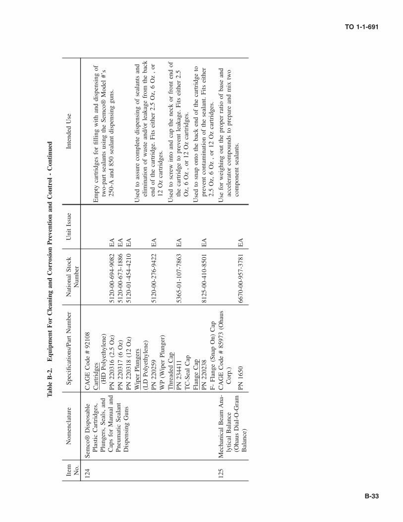
Tabl
eB
-2.
Equ
ipm
ent
For
Cle
anin
gan
dC
orro
sion
Pre
vent
ion
and
Con
trol
-C
onti
nued
Item No.
Nom
encl
atur
eSp
ecifi
catio
ns/P
art
Num
ber
Nat
iona
lSt
ock
Num
ber
Uni
tIs
sue
Inte
nded
Use
124
Sem
co®
Dis
posa
ble
Plas
ticC
artr
idge
s,Pl
unge
rs,
Seal
s,an
dC
aps
for
Man
ual
and
Pneu
mat
icSe
alan
tD
ispe
nsin
gG
uns
CA
GE
Cod
e#
9210
8C
artr
idge
s(H
DPo
lyet
hyle
ne)
Em
pty
cart
ridg
esfo
rfil
ling
with
and
disp
ensi
ngof
two-
part
seal
ants
usin
gth
eSe
mco
®M
odel
#’s
250-
Aan
d85
0se
alan
tdi
spen
sing
guns
.PN
2203
16(2
.5O
z)51
20-0
0-69
4-90
82E
APN
2203
17(6
Oz)
5120
-00-
673-
1886
EA
PN22
0318
(12
Oz)
5120
-01-
454-
4210
EA
Wip
erPl
unge
rsU
sed
toas
sure
com
plet
edi
spen
sing
ofse
alan
tsan
del
imin
atio
nof
was
tean
d/or
leak
age
from
the
back
end
ofth
eca
rtri
dge.
Fits
eith
er2.
5O
z,6
Oz
,or
12O
zca
rtri
dges
.
(LD
Poly
ethy
lene
)PN
2202
5951
20-0
0-27
6-94
22E
AW
P(W
iper
Plun
ger)
Thr
eade
dC
apU
sed
tosc
rew
into
and
cap
the
neck
orfr
ont
end
ofth
eca
rtri
dge
topr
even
tle
akag
e.Fi
tsei
ther
2.5
Oz,
6O
z,
or12
Oz
cart
ridg
es.
PN23
4411
5365
-01-
107-
7863
EA
TC
-Sea
lC
apFl
ange
Cap
Use
dto
snap
onto
the
back
end
ofth
eca
rtri
dge
topr
even
tco
ntam
inat
ion
ofth
ese
alan
t.Fi
tsei
ther
2.5
Oz,
6O
z,
or12
Oz
cart
ridg
es.
PN22
0238
8125
-00-
410-
8501
EA
F-Fl
ange
(Sna
pO
n)C
ap12
5M
echa
nica
lB
eam
Ana
-ly
tical
Bal
ance
(Oha
usD
ial-
O-G
ram
Bal
ance
)
CA
GE
Cod
e#
8597
3(O
haus
Cor
p.)
Use
for
wei
ghin
gou
tth
epr
oper
ratio
ofba
sean
dac
cele
rato
rco
mpo
unds
topr
epar
ean
dm
ixtw
oco
mpo
nent
seal
ants
.PN
1650
6670
-00-
957-
3781
EA
TO 1-1-691
B-33

Tabl
eB
-2.
Equ
ipm
ent
For
Cle
anin
gan
dC
orro
sion
Pre
vent
ion
and
Con
trol
-C
onti
nued
Item No.
Nom
encl
atur
eSp
ecifi
catio
ns/P
art
Num
ber
Nat
iona
lSt
ock
Num
ber
Uni
tIs
sue
Inte
nded
Use
126
Sem
co®
Seal
ant
Smoo
thin
gTo
ols
(Fib
ergl
ass
Rei
n-fo
rced
Plas
tic)
CA
GE
Cod
e#
9210
8Sp
atul
asan
dsp
read
ers
for
tool
ing
and
smoo
thin
gse
alan
tsan
dad
hesi
ves.
For
addi
tiona
lin
form
atio
nre
fer
toFi
gure
6-5.
Seal
ant
Spat
ulas
PN23
1349
5120
-01-
337-
9415
EA
9½in
L;
roun
ded
ends
-9/
16in
D&
¼in
DPN
2262
4151
20-0
1-29
7-70
15E
A7¼
inL
;sq
end-
3/16
inW
&rd
.en
d-3⁄8
inD
PN22
6242
5120
-01-
297-
7016
EA
7¼in
L;
sqen
d-9/
32in
W&
rd.
end
1⁄8
inD
PN22
6243
5120
-01-
297-
7017
EA
7¼in
L;
sqen
ds-
3⁄8
inW
&15
/32
inW
Spat
ula
Kit
The
kit
incl
udes
spat
ulas
PN’s
2262
41,
2262
42,
and
2262
43sp
atul
as.
PN22
6244
5120
-00-
056-
3237
KT
Seal
ant
Scra
per
Use
dfo
rei
ther
spre
adin
gor
rem
oval
ofse
alan
tfr
omal
lsu
rfac
es(5
13/1
6in
L;
one
sqen
d-¾
inW
).PN
2343
5051
20-0
1-29
8-61
21E
A
Seal
ant
Spre
ader
Use
dfo
rsp
read
ing
seal
ants
orad
hesi
ves
onto
flat
surf
aces
,in
part
icul
aron
ala
rge
area
(4in
Lx
23/
16in
W).
PN22
9394
5120
-01-
337-
9416
EA
Com
bSp
read
erU
sed
tosp
read
seal
ants
orad
hesi
ves
whi
lem
ain-
tain
ing
aun
ifor
mth
ickn
ess
and
agr
oove
dpa
ttern
(3in
Lx
3in
Ww
ithsa
wto
oth
edge
s).
PN22
9395
Ope
nPu
rcha
seE
A
127
Plas
ticN
ozzl
es,
Dis
-po
sabl
e(¼
inor
½in
NPT
mal
eth
read
eden
d)
CA
GE
Cod
e#
9210
8(S
emco
®M
odel
#’s)
Noz
zles
used
for
disp
ensi
ngse
alan
tsw
hen
atta
ched
toSe
mco
®ca
rtri
dges
(Ite
m#
124)
.R
efer
toFi
g-ur
e6-
2fo
rno
zzle
shap
esto
dete
rmin
eth
eap
pro-
pria
teM
odel
#fo
rth
ejo
b.St
anda
rdN
ozzl
esA
pply
ing
seal
ant
inbu
ttse
amga
ps.
No.
252
(PN
2205
38)
5120
-00-
167-
0150
EA
St2½
inL
with
1/16
inor
ifice
.N
o.25
4(P
N22
0540
)51
20-0
0-67
3-18
85E
ASt
2½in
Lw
ith1⁄8
inor
ifice
.N
o.25
5(P
N23
3495
)O
pen
Purc
hase
EA
St2½
inL
with
noor
ifice
(cut
tosu
it).
No.
410
(PN
2205
42)
5120
-00-
801-
0949
EA
St4
inL
with
1/32
inor
ifice
.N
o.41
0(P
N22
0543
)51
20-0
0-05
5-40
63E
A45
°an
gle
with
1/32
inor
ifice
.N
o.41
5(P
N22
7613
)51
20-0
1-38
6-44
80E
ASt
4in
Lw
ithno
orifi
ce(c
utto
suit)
.N
o.42
0(P
N22
0544
)51
20-0
0-04
2-65
77E
ASt
4in
Lw
ith1/
16in
orifi
ce.
No.
430
(PN
2205
48)
5120
-00-
967-
8151
EA
St4
inL
with
3/32
inor
ifice
.N
o.43
0(P
N22
0549
)51
20-0
0-05
5-40
62E
A45
°an
gle
with
3/32
inor
ifice
.N
o.44
0(P
N22
0550
)51
20-0
0-77
3-37
91E
ASt
4in
Lw
ith1⁄8
inor
ifice
.N
o.62
0(P
N22
0553
)51
20-0
0-16
7-01
52E
ASt
6in
Lw
ith1/
16in
orifi
ce.
No.
620
(PN
2205
54)
5120
-00-
966-
5373
EA
45°
angl
ew
ith1/
16in
orifi
ce.
TO 1-1-691
B-34 Change 1

Tabl
eB
-2.
Equ
ipm
ent
For
Cle
anin
gan
dC
orro
sion
Pre
vent
ion
and
Con
trol
-C
onti
nued
Item No.
Nom
encl
atur
eSp
ecifi
catio
ns/P
art
Num
ber
Nat
iona
lSt
ock
Num
ber
Uni
tIs
sue
Inte
nded
Use
127 C
ont.
No.
640
(PN
2205
55)
5120
-00-
822-
7194
EA
St6
inL
with
1⁄8
inor
ifice
.
No.
640
(PN
2205
56)
5120
-00-
167-
0153
EA
30°
angl
ew
ith1⁄8
inor
ifice
.N
o.64
0(P
N22
0551
)51
20-0
0-67
0-11
86E
A45
°an
gle
with
1⁄8
inor
ifice
.N
o.65
0(P
N22
4494
)O
pen
Purc
hase
EA
St6
inL
with
1⁄8
inor
ifice
.N
o.82
0(P
N22
0557
)51
20-0
0-96
6-82
70E
ASt
8in
Lw
ith1/
16in
orifi
ce.
No.
820
(PN
2205
58)
5120
-00-
966-
5371
EA
45°
angl
ew
ith1/
16in
orifi
ce.
No.
840
(PN
2205
59)
5120
-00-
966-
5372
EA
St8
inL
with
1⁄8
inor
ifice
.N
o.84
0(P
N22
0560
)51
20-0
0-96
6-53
82E
A45
°an
gle
with
1⁄8
inor
ifice
.N
o.86
90(P
N22
0606
)51
20-0
0-96
6-82
43E
A9
inve
ntdu
ckno
zzle
with
3/32
inor
ifice
.N
o.10
02(P
N22
0561
)51
20-0
0-05
5-40
55E
ASt
10in
Lw
ith1/
16in
orifi
ce.
No.
1004
(PN
2205
63)
5120
-00-
055-
4054
EA
St10
inL
with
1⁄8
inor
ifice
.N
o.10
10(P
N22
0565
)51
20-0
0-05
5-40
58E
ASt
10in
Lw
ith5/
16in
orifi
ce.
Fille
tN
ozzl
esA
pply
ing
seal
ant
fille
tsov
erla
pjo
ints
.N
o.42
5(P
N23
2499
)51
20-0
1-38
6-42
74E
ASt
4in
Lw
ith3⁄8
inx
1⁄8
inor
ifice
.N
o.42
6(P
N23
2500
)O
pen
Purc
hase
EA
St4
inL
with
3⁄8
inx
1⁄8
inor
ifice
.N
o.42
7(P
N23
2501
)O
pen
Purc
hase
EA
St4
inL
with
3⁄8
inx
1⁄8
inor
ifice
.N
o.42
8(P
N23
2502
)O
pen
Purc
hase
EA
St4
inL
with
3⁄8
inx
1⁄8
inor
ifice
.N
o.42
9(P
N23
2590
)O
pen
Purc
hase
EA
St4
inL
with
1/16
inx
½in
orifi
ce.
Rib
bon
Noz
zles
App
lyin
gse
alan
tfo
rfa
ysu
rfac
ese
alin
g.N
o.86
07(P
N22
0568
)51
20-0
0-96
6-53
81E
ASt
57/ 8
inL
with
1/16
inx
¼in
orifi
ce.
No.
8608
(PN
2205
69)
5120
-00-
966-
8244
EA
St4
inL
with
11/6
4in
orifi
ce(fl
ared
tip)
No.
8610
(PN
2205
70)
5120
-00-
299-
6790
EA
St41
⁄8in
Lw
ith3/
64in
x9/
64in
orifi
ce.
No.
8613
(PN
2205
72)
5120
-00-
966-
5379
EA
St5
inL
with
3/64
inx
3⁄8
inor
ifice
.N
o.86
15(P
N22
0574
)51
20-0
0-96
6-53
78E
ASt
4in
Lw
ith1/
16in
x½
inor
ifice
.N
o.86
16(P
N22
0577
)51
20-0
1-38
5-50
74E
A2
3/16
inL
with
7/32
inor
ifice
(for
win
dshi
eld
fil-
lets
).N
o.86
30(P
N22
0589
)51
20-0
0-96
6-53
77E
ASt
4in
Lw
ith1⁄8
inx
1¾in
orifi
ce.
No.
8630
-9(P
N22
0582
)51
20-0
0-96
6-53
76E
ASt
47⁄8
inL
with
1⁄8
inx
1¾in
orifi
ce&
anat
-ta
ched
brus
hsp
read
er.
No.
8642
(PN
2205
85)
5120
-00-
293-
4676
EA
St4
inL
with
3/16
inor
ifice
.N
o.86
43(P
N22
0586
)51
20-0
0-77
5-16
70E
ASt
43⁄8
inL
with
1⁄8
inx
¾in
orifi
ce&
spat
ula
like
exte
nsio
nsp
read
er.
TO 1-1-691
Change 1 B-35

Tabl
eB
-2.
Equ
ipm
ent
For
Cle
anin
gan
dC
orro
sion
Pre
vent
ion
and
Con
trol
-C
onti
nued
Item No.
Nom
encl
atur
eSp
ecifi
catio
ns/P
art
Num
ber
Nat
iona
lSt
ock
Num
ber
Uni
tIs
sue
Inte
nded
Use
127 C
ont.
No.
8645
(PN
2205
87)
5120
-00-
138-
1658
EA
St4
3/16
inL
with
1⁄8
inx
1in
orifi
ce&
spat
ula
like
exte
nsio
nsp
read
er.
No.
8646
(PN
2205
88)
5120
-00-
966-
5374
EA
St3
15/1
6in
Lw
ith1⁄8
inx
¾in
orifi
ce&
saw
-to
oth
trow
elex
tens
ion
spre
ader
.N
o.86
48(P
N22
0589
)51
20-0
0-96
6-53
75E
ASt
53/
16in
Lw
ith1⁄8
inx
¾in
orifi
ce&
spat
ula
like
exte
nsio
nsp
read
er.
Ext
ensi
onN
ozzl
eN
o.60
0E(P
N22
0552
)51
20-0
0-67
0-11
87E
A6
3⁄8
inL
roun
dex
tens
ion
tube
.Fl
oorb
oard
Noz
zle
App
lyin
gse
alan
ton
floor
boar
dfa
ying
surf
aces
PN23
1674
Ope
nPu
rcha
seE
ASt
13⁄8
inL
with
½in
Dct
r.bu
tton
surr
ound
edw
ith12
EA
1/32
inor
ifice
sFu
nnel
Noz
zle
Filli
ngla
rge
cavi
ties
with
seal
ant.
1in
(PN
2317
18)
Ope
nPu
rcha
seE
ASt
13⁄8
inL
with
½in
funn
elty
peor
ifice
.2
in(P
N23
1348
)O
pen
Purc
hase
EA
St31
⁄8in
Lw
ith1
27/3
2in
funn
elty
peor
ifice
.N
ozzl
eA
dapt
erPN
2293
06O
pen
Purc
hase
EA
¼in
NPT
mal
eth
read
&½
inN
PTfe
mal
eth
read
tore
ceiv
e½
inN
PTth
read
nozz
le.
Edg
eFi
llN
ozzl
eN
o.44
4(P
N23
4164
)O
pen
Purc
hase
EA
A0.
40in
thic
kfla
nge
guid
esit
alon
ga
pane
led
ge/
corn
erto
prov
ide
asl
ight
lyro
unde
ded
ge/c
orne
rfil
l.
TO 1-1-691
B-36 Change 1

Tabl
eB
-2.
Equ
ipm
ent
For
Cle
anin
gan
dC
orro
sion
Pre
vent
ion
and
Con
trol
-C
onti
nued
Item No.
Nom
encl
atur
eSp
ecifi
catio
ns/P
art
Num
ber
Nat
iona
lSt
ock
Num
ber
Uni
tIs
sue
Inte
nded
Use
128
Fast
ener
Seal
ing
Noz
zles
(Cou
nter
sink
Noz
zles
)
CA
GE
Cod
e#
9210
8U
sed
toap
ply
the
requ
ired
amou
ntof
seal
ant
inth
eco
unte
rsin
kar
eaof
fast
ener
hole
spr
ior
toin
stal
la-
tion
ofth
efa
sten
ers.
The
yha
veth
read
eden
dsto
fitin
toth
eSe
mco
®pl
astic
cart
ridg
es(I
tem
#12
4).
The
nozz
les
are
colo
rco
ded
for
iden
tifica
-tio
n.R
efer
toFi
gure
6-3d
eter
min
eth
eap
prop
riat
eno
zzle
confi
gura
tion
and
size
for
the
job
asw
ell
asop
erat
ion
inst
ruct
ions
.
PN23
3244
Ope
nPu
rcha
seE
ASi
ze:
3/32
in-1
⁄8in
(Red
)PN
2332
43O
pen
Purc
hase
EA
Size
:3/
16in
-¼in
(Whi
te)
PN23
3451
Ope
nPu
rcha
seE
ASi
ze:
5/16
in-3
⁄8in
(Blu
e)PN
2313
19O
pen
Purc
hase
EA
Size
:¼
inho
le(Y
ello
w)
PN23
1320
Ope
nPu
rcha
seE
ASi
ze:
5/16
inho
le(G
rey)
PN23
1321
Ope
nPu
rcha
seE
ASi
ze:
3⁄8
inho
le(G
reen
)PN
2315
60O
pen
Purc
hase
EA
Size
:7/
16in
hole
(Red
)PN
2315
59O
pen
Purc
hase
EA
Size
:½
inho
le(B
lue)
TO 1-1-691
Change 1 B-37

Tabl
eB
-2.
Equ
ipm
ent
For
Cle
anin
gan
dC
orro
sion
Pre
vent
ion
and
Con
trol
-C
onti
nued
Item No.
Nom
encl
atur
eSp
ecifi
catio
ns/P
art
Num
ber
Nat
iona
lSt
ock
Num
ber
Uni
tIs
sue
Inte
nded
Use
129
Riv
etN
ozzl
esC
AG
EC
ode
#92
108
Use
dto
appl
yth
ere
quir
edam
ount
ofse
alan
tin
the
coun
ter
sink
and
hole
prio
rto
fast
enin
gpa
rts
with
rive
ts.
The
spri
ng-l
oade
dtip
ofth
eno
zzle
acts
asa
chec
kva
lve
allo
win
gpr
ecis
esh
ots
ofm
ater
ial
tobe
disp
ense
d.T
hey
have
thre
aded
ends
tofit
into
the
Sem
co®
plas
ticca
rtri
dges
.T
heno
zzle
sar
eco
lor
code
dfo
rid
entifi
catio
n.R
efer
toFi
gure
6-4
tode
term
ine
the
appr
opri
ate
nozz
leco
nfigu
ra-
tion
and
size
for
the
job
asw
ell
asop
erat
ion
in-
stru
ctio
ns.
PN23
4285
Ope
nPu
rcha
seE
ASi
ze:
3/32
in(G
erm
aine
Gre
en)
PN22
6837
5130
-01-
413-
8733
EA
Size
:1⁄8
in(B
lue)
PN22
6838
Ope
nPu
rcha
seE
ASi
ze:
5/32
in(B
lack
)PN
2268
39O
pen
Purc
hase
EA
Size
:3/
16in
(Whi
te)
PN23
4260
Ope
nPu
rcha
seE
ASi
ze:
3/16
info
r12
0°co
unte
r-si
nk(G
reen
)PN
2342
84O
pen
Purc
hase
EA
Size
:7/
32in
(Lig
htB
lue)
PN22
6840
5120
-01-
416-
1683
EA
Size
:¼
in(R
ed)
PN23
3051
Ope
nPu
rcha
seE
ASi
ze:
5/16
in(O
rang
e)PN
:23
3052
Ope
nPu
rcha
seE
ASi
ze:
3⁄8
in(Y
ello
w)
130
Rol
ler
Noz
zles
(¼
inN
PTm
ale
thre
aded
end)
CA
GE
Cod
e#
9210
8U
sed
toap
ply
adhe
sive
san
dse
alan
tsev
enly
over
wid
ear
eas
ofsu
bstr
ate
(e.g
.fa
ying
surf
ace)
.T
hey
have
thre
aded
ends
tofit
into
the
Sem
co®
plas
ticca
rtri
dges
.T
hey
can
beso
lven
tcl
eane
dfo
rre
-use
.R
olle
rN
ozzl
eA
ssem
bly
PN23
2693
Ope
nPu
rcha
seE
A(1
inW
Rol
ler)
PN23
2692
Ope
nPu
rcha
seE
A(2
inW
Rol
ler)
Rep
lace
men
tR
olle
r
PN23
2701
5120
-01-
440-
6984
EA
(1in
WR
olle
r)PN
2327
02O
pen
Purc
hase
EA
(2in
WR
olle
r)
TO 1-1-691
B-38 Change 1

Tabl
eB
-2.
Equ
ipm
ent
For
Cle
anin
gan
dC
orro
sion
Pre
vent
ion
and
Con
trol
-C
onti
nued
Item No.
Nom
encl
atur
eSp
ecifi
catio
ns/P
art
Num
ber
Nat
iona
lSt
ock
Num
ber
Uni
tIs
sue
Inte
nded
Use
131
Cha
lk,
Mar
king
As-
sort
edC
olor
sA
-A-8
075
10-0
0-28
2-69
24A
TId
entifi
catio
n/M
arki
ngof
corr
oded
area
s.
Whi
teA
-A-3
1875
10-0
0-22
3-67
06G
R
TO 1-1-691
Change 1 B-39

Figure B-1. Back Mounted Full Facepiece Respirator
TO 1-1-691
B-40

Figure B-2. Front Mounted Full Facepiece Respirator
TO 1-1-691
B-41

Figure B-3. Hooded Air Respirator System
TO 1-1-691
B-42
GLOSSARY
A
Active metal — A metal prone to corrode or being corroded.
Additive — A compound added for a particular purpose; forexample, additives in fuel and lubricants can preventcorrosion, gum formation, varnishing, sludge formation,and knocking.
Aeration (Oxygen Concentration) Cell — An electrolyticcell in which the driving force to cause corrosion resultsfrom a difference in the amount of oxygen in solution at onepoint as compared to another. Corrosion is accelerated inareas where the oxygen concentrated is least, for example,in a crevice or under packing or gaskets.
Alkaline — Having a pH of more than 7.
Alloy — A combination of two or more metals.
Anaerobic — A process which is capable of occurring in theabsence of oxygen.
Anion — A negatively charged ion of an electrolyte whichmigrates toward the anode. The chloride ion in sea water isan anion.
Anode — The electrode of a corrosion cell at which oxida-tion or corrosion occurs. It may be a small area on thesurface of a metal or alloy, such as that where a pit develops,or it may be the more active metal in a cell composed of twodissimilar metals, (i.e., the one with the greater tendency togo into solution). The corrosion process involves the changeof metal atoms into cations with a liberation of electronsthat migrate through the metal to the cathode of the cell.
Anodic protection — The reduction or elimination of corro-sion of a metal achieved by making current flow from it tothe solution by connecting it to the positive pole of a sourceof current. Under most conditions, as the potential of aninitially active metal is gradually shifted in a more nobledirection, such as by potentiostatic means, the corrosioncurrent gradually increases. However, with suitable combi-nations of metal and solution, a critical potential is soonreached. Imposing a potential higher than the criticalpotential, causes the current to drop to a very low value, andthe metal becomes passive. The potential of metal has to beregulated by a potentiostat.
Anodize — To subject (a metal) to electrolytic action as theanode of a cell in order to coat with a protective ordecorative film (anodic oxidation film).
Austenitic — A term applied to that condition of ironassociated with a change in crystal structure that makes itnon-magnetic. This occurs with ordinary iron at an elevatedtemperature. When sufficient chromium and nickel arepresent, steel becomes austenitic (non-magnetic) at atmo-sphere temperatures. This is the case with the many stainlessalloys that combine about 18% chromium and 8% or morenickel with iron.
C
Cathode — The less active electrode of a corrosion cell,where the action of the current causes reduction and nearlycomplete elimination of corrosion.
Cathodic Protection — The reduction or elimination ofcorrosion of a metal that is achieved by making current flowto it from a solution, such as connecting it to the negativepole of some source current. The source of the protectivecurrent may be sacrificial metal, such as magnesium, zinc,or aluminum. The current may also be derived from arectifier, generator, or battery applied through an appropri-ate anode which may be connected by the applied current(as in the case of steel), or which remains substantiallyunaffected by the current, as in the case of platinum.Cathodic protection becomes complete when anodic reac-tions are completely suppressed and only cathodic reactionsoccur on the metal surface.
Cation — A positively charged ion in an electrolyte whichmigrates toward the cathode. Metallic ions, such as iron orcopper, are cations.
Caustic Embrittlement — The result of the combined actionof tensile stress and corrosion in an alkaline solution thatcauses embrittlement. This is the most frequently encoun-tered in the laps of riveted boilers where the requiredconcentration of the alkali in the boiler water occurs.
Cell — In corrosion processes, a cell is a source of electricalcurrent that is responsible for corrosion. It consists of ananode and a cathode immersed in an electrolyte andelectrically joined together. The anode and cathode may beseparate metals dissimilar areas on the same metal.
Chemical Conversion Coating — A film deliberately pro-duced on a metal by immersing it in, brushing it with, orspraying it with a selected chemical solution for the purposeof providing improved corrosion resistance to the metal orincreasing the adhesion of organic coatings to be appliedlater. Coatings covered by MIL-DTL-5541 are examples.
TO 1-1-691
Change 1 Glossary 1

Clear water — Colorless water containing no visiblesuspended particles.
Combustible Liquid — Any liquid having a flashpoint ator above 100° F, but below 200° F.
Concentration Cell — An electrolytic cell consisting ofan electrolyte and two electrodes of the same metal oralloy that develops a difference in potential as a resultof a difference in concentration of ions (most oftenmetal ions) or oxygen at different points in a solution.
Corrosion Fatigue — A reduction in the ability of ametal to withstand cyclic stress caused by its exposureto a corrosive environment.
Corrosion Rate — The speed of corrosion attack. It isusually expressed in terms of weight loss per unit oftime.
Couple — Two or more metals or alloys in electricalcontact with each other so that they can act as theelectrodes of a cell if they are immersed in an electro-lyte.
Cracking —
a. — Localized breaking of a paint film to expose theunderlying material.
b. — Breaking of metal or alloy in a brittle fashion alonga narrow path or network.
Crevice Corrosion — Corrosion occurring within acrevice formed by two or more parts of the same ordifferent metals or formed by a metal and non-metallicmaterial. Stainless steel and aluminum alloys are par-ticularly susceptible to crevice corrosion.
Critical Humidity — The relative humidity, under a spe-cific set of conditions, at which a metal or an alloy willbegin to corrode. In the presence of hygroscopic(moisture absorptive) solids or corrosion products, thecritical humidity will be lowered. Steel will not corrode ifthe relative humidity is less than 30% in a marineatmosphere.
D
Deposit Attack — When foreign material (dirt, corro-sion products, etc.) is deposited on the surface of ametal, it may shield the metal from the oxygen neces-sary to regenerate a protective oxide layer. An oxygen
concentration cell is formed, and serious corrosionmay result. Also called an active-passive cell.
E
Electrochemical Corrosion — Corrosion which occurswhen current flows between cathodic and anodic areason metallic surfaces.
Electrode — A metal or alloy that is in contact withelectrolyte and serves as the site where electricitypasses in either direction between the electrolyte andmetal. The current in the electrode itself is a flow ofelectrons, whereas, in the electrolyte, ions carry elec-tric charges and their orderly movement in solutionconstitutes a flow of current in the electrolyte.
Electrolysis — In the strict sense of the term, electroly-sis concerns chemical changes in the solution orelectrolyte due to the passage of current. Its relation tocorrosion arises only if the corrosion process alters themake-up of the solution. Hence, since the term is mostclosely related to the solution phenomena than tocorrosion, its use to indicate corrosion should bediscouraged.
Electrolyte — Any substance which, in solution orfused, exists as electrically charged ions that renderthe liquid capable of conducting a current. Solubleacids, bases, and salts, such as sea water, are elec-trolytes.
Electromagnetic Interference (EMI) — Radiation gen-erated from electromagnetic fields which are producedby radar antennas, Radio Frequency (RF) antennas,onboard transmitters, certain poorly designed avionicsunits, electric motors, and lightning and other naturaleffects. This type of radiation can interfere with aircraftavionics systems causing electrical malfunctions.
Electromotive Force (EMF) Series — A list of ele-ments according to their standard electrode potentials.The more negative the potential the greater the ten-dency of the metal to corrode. This series is useful instudies of thermodynamic properties, but does notindicate the rates of corrosion. A hydrogen gas elec-trode is the standard reference and its potential isdesignated as zero. All potentials are positive or nega-tive with respect to the hydrogen electrode. In thiscountry, the potentials of zinc and iron are designatedas negative and those of copper and platinum aspositive.
TO 1-1-691
Glossary 2

Embrittlement — Severe loss of ductility of a metalalloy that results in a brittle fashion.
Erosion — Destruction of a metal by the combinedaction of corrosion and abrasion or attrition by a liquidor gas with or without suspended matter.
Exfoliation — The breaking away of material from itssurface in flakes or layers.
F
Faying Surfaces — The common surfaces betweenmating parts.
Filiform Corrosion — Corrosion that develops undercoatings on metals in fine ragged hairlines, usuallywavy or curved and randomly distributed.
Film — A thin layer of material that may or may not bevisible.
Flammable Liquid — Any liquid having a flash point of100° F or less.
Flashpoint — The minimum temperature at which aliquid gives off an ignitable vapor in any one of theclosed cup flashpoint testers (Penssky-Martens, Tagli-bue, or Seta-Flash).
Fretting Corrosion — Corrosion at the interface of twoconnecting surfaces, usually under high pressure andsubject to very minute slippage due to relative vibrationof surfaces that ordinarily are not supposed to moverelative to each other, such as a shrink fit.
G
Galvanic — The flow of direct current between dissimi-lar metals.
Galvanic Corrosion — The accelerated corrosion of anactive metal caused by the presence of a less activemetal in the same solution and in contact with the moreactive metal.
Galvanic Series — A list of metals and alloys arrangedin order of their relative potentials in a given environ-ment. The order of their arrangement in this list may bedifferent in other environments.
H
Hazardous Material — A material which may pose athreat to human health or the environment when im-properly handled or disposed of.
Hazardous Waste — Waste which is characterized bythe Environmental Protection Agency (EPA) as 1)ignitable, 2) corrosive, 3) reactive, or 4) toxic, asdefined in 40 CFR 261, or is a listed hazardous wasteidentified in that regulation.
Hydrogen Embrittlement — Loss of ductility of a metal,caused by the entrance or absorption of hydrogen ionsinto the metal, as in the pickling of metal.
I
Inhibitor — As applied to corrosion, a chemical sub-stance or mixture which, when added in small amountsto a solution, markedly decreases corrosion.
Inorganic Coatings — Electroplated coatings, conver-sion coatings, anodic coatings, phosphate coatings,and oxide coatings.
Ion — An electrically charged atom or group of atoms.The sign of the charge is positive in the case of cationsand negative in the case of anions.
L
Local Cell — A cell in which the driving force is due toa difference in potential between areas on a metal oralloy surface immersed in an electrolyte. The potentialdifference may be due to inclusions, lack of homoge-neity, varying concentration of the solution with respectto oxygen or metal ions, etc.
M
Metal Ion Concentration Cell — A cell established on ametal surface due to different concentrations of its ionsin the electrolyte which is in contact with the metalsurface. These variations in concentration result inlocal differences in potential, thus allowing the estab-lishment of a local cell.
Mill Scale — The heavy oxide layer formed during hotfabrication or heat treatment of metals. The term ismost frequently applied to the scale of mixed ironoxides on iron and steel.
Mottling — Appearance of spotting or blotches of dif-ferent color or shades of coloring.
N
Noble Metal — A metal usually found as an uncom-bined metal in nature. Platinum, gold, and silver arenoble metals.
TO 1-1-691
Glossary 3

Non-Destructive Inspection — A method used tocheck the soundness of a material or a part withoutimpairing or destroying the serviceability of the part.
O
Organic Coatings — Paints, lacquers, plastics,greases, etc.
Oxidation — Any change involving the loss of electronsby an atom. Any corrosion process involves oxidationof the metal in a true chemical sense. It also may implythe destruction of metal or alloy as a result of the directaction of oxygen on the metal, e.g., the scaling of steelat high temperatures.
Ozone — A triatomic (O3) form of oxygen.
R
Room Temperature Vulcanizing (RTV) — A processfor curing of synthetic rubber or plastic materials whichoccurs at room temperature.
S
Solvent — A liquid substance capable of dissolving ordispersing one or more other substances.
T
Thixotropic — Gel-like in physical property.
Titration — A method or the process of determining theconcentration of a dissolved substance in terms of thesmallest amount of reagent of known concentrationrequired to bring about a given effect or reaction with aknown volume of the test solution.
U
Ultraviolet (UV) Light — Light (electromagnetic radia-tion) of a wavelength shorter than visible light butlonger than X-ray radiation. Long wavelength UV fromthe sun causes sunburn. Short wavelength UV fromunfiltered UV lamps can damage unprotected eyes.
Uniform Surface Corrosion — Corrosive etching ofmetal involving only the surface.
W
Wording — The following definitions are adhered to inpreparing this manual:
May — is used only when a procedure is optional.
Shall — is used only when a procedure is mandatory.
Should — is used only when a procedure is recom-mended but not mandatory.
Will — is used to indicate future action but never toindicate a mandatory procedure.
TO 1-1-691
Glossary 4

INDEXSubject Paragraph, Figure,
Table Number
AAIR INTAKE DUCTS FOR JET AIRCRAFT . . . . . . . . . . . . . . . . . . . . . . . . . . . . . . . . . . . . . . . . . . . . . . . 7.15APPLICATION OF POLISH AND WAX . . . . . . . . . . . . . . . . . . . . . . . . . . . . . . . . . . . . . . . . . . . . . . . . . . 3.8APPLICATIONS . . . . . . . . . . . . . . . . . . . . . . . . . . . . . . . . . . . . . . . . . . . . . . . . . . . . . . . . . . . . . . . . . . . 6.2
BBATTERY COMPARTMENTS, BOXES, AND ADJACENT AREAS . . . . . . . . . . . . . . . . . . . . . . . . . . . . . . . 7.2
Cleaning and Neutralizing Procedures . . . . . . . . . . . . . . . . . . . . . . . . . . . . . . . . . . . . . . . . . . . . . . . . . . 7.2.2Paint Systems . . . . . . . . . . . . . . . . . . . . . . . . . . . . . . . . . . . . . . . . . . . . . . . . . . . . . . . . . . . . . . . . . . 7.2.3
BERYLLIUM-COPPER ALLOYS, BERYLLIUM-ALUMINUM ALLOYS, AND BERYLLIUM OXIDE . . . . . . 7.20Corrosion Removal and Treatment . . . . . . . . . . . . . . . . . . . . . . . . . . . . . . . . . . . . . . . . . . . . . . . . . . . 7.20.1Depot Maintenance . . . . . . . . . . . . . . . . . . . . . . . . . . . . . . . . . . . . . . . . . . . . . . . . . . . . . . . . . . . . . 7.20.2
CCHEMICAL DEFINITIONS . . . . . . . . . . . . . . . . . . . . . . . . . . . . . . . . . . . . . . . . . . . . . . . . . . . . . . . . . . . 2.3
Atom . . . . . . . . . . . . . . . . . . . . . . . . . . . . . . . . . . . . . . . . . . . . . . . . . . . . . . . . . . . . . . . . . . . . . . . . 2.3.1Electrolyte . . . . . . . . . . . . . . . . . . . . . . . . . . . . . . . . . . . . . . . . . . . . . . . . . . . . . . . . . . . . . . . . . . . . 2.3.4Electron . . . . . . . . . . . . . . . . . . . . . . . . . . . . . . . . . . . . . . . . . . . . . . . . . . . . . . . . . . . . . . . . . . . . . . 2.3.2Ions . . . . . . . . . . . . . . . . . . . . . . . . . . . . . . . . . . . . . . . . . . . . . . . . . . . . . . . . . . . . . . . . . . . . . . . . . 2.3.3
CLEANING COMPOUNDS . . . . . . . . . . . . . . . . . . . . . . . . . . . . . . . . . . . . . . . . . . . . . . . . . . . . . . . . . . . 3.3Alkaline Cleaners . . . . . . . . . . . . . . . . . . . . . . . . . . . . . . . . . . . . . . . . . . . . . . . . . . . . . . . . . . . . . . . 3.3.1Aqueous Parts Washer Cleaning Solutions . . . . . . . . . . . . . . . . . . . . . . . . . . . . . . . . . . . . . . . . . . . . . . . 3.3.3Dilution . . . . . . . . . . . . . . . . . . . . . . . . . . . . . . . . . . . . . . . . . . . . . . . . . . . . . . . . . . . . . . . . . . . . . . 3.3.7Miscellaneous Cleaning Agents . . . . . . . . . . . . . . . . . . . . . . . . . . . . . . . . . . . . . . . . . . . . . . . . . . . . . . 3.3.5Solvents . . . . . . . . . . . . . . . . . . . . . . . . . . . . . . . . . . . . . . . . . . . . . . . . . . . . . . . . . . . . . . . . . . . . . . 3.3.4Steam Cleaning . . . . . . . . . . . . . . . . . . . . . . . . . . . . . . . . . . . . . . . . . . . . . . . . . . . . . . . . . . . . . . . . . 3.3.6
CLEANING EQUIPMENT . . . . . . . . . . . . . . . . . . . . . . . . . . . . . . . . . . . . . . . . . . . . . . . . . . . . . . . . . . . . 3.4Aqueous Parts Washers . . . . . . . . . . . . . . . . . . . . . . . . . . . . . . . . . . . . . . . . . . . . . . . . . . . . . . . . . . . 3.4.9High Pressure/Hot Water Wash Equipment . . . . . . . . . . . . . . . . . . . . . . . . . . . . . . . . . . . . . . . . . . . . . . 3.4.1Miscellaneous Equipment . . . . . . . . . . . . . . . . . . . . . . . . . . . . . . . . . . . . . . . . . . . . . . . . . . . . . . . . . 3.4.10Miscellaneous Large Cleaning Equipment . . . . . . . . . . . . . . . . . . . . . . . . . . . . . . . . . . . . . . . . . . . . . . . 3.4.5Pneumatic Vacuum Cleaner . . . . . . . . . . . . . . . . . . . . . . . . . . . . . . . . . . . . . . . . . . . . . . . . . . . . . . . . . 3.4.7Portable, 15 Gallon, Foam Generating, Cleaning Unit . . . . . . . . . . . . . . . . . . . . . . . . . . . . . . . . . . . . . . . 3.4.2Portable, 45 Gallon, Foam Generating Cleaning Unit . . . . . . . . . . . . . . . . . . . . . . . . . . . . . . . . . . . . . . . 3.4.3Spray Cleaning Guns for Solvents . . . . . . . . . . . . . . . . . . . . . . . . . . . . . . . . . . . . . . . . . . . . . . . . . . . . 3.4.6Turbine Engine Compressor Cleaning Equipment . . . . . . . . . . . . . . . . . . . . . . . . . . . . . . . . . . . . . . . . . . 3.4.4Universal Wash Unit . . . . . . . . . . . . . . . . . . . . . . . . . . . . . . . . . . . . . . . . . . . . . . . . . . . . . . . . . . . . . 3.4.8
CLEANING PROCEDURES . . . . . . . . . . . . . . . . . . . . . . . . . . . . . . . . . . . . . . . . . . . . . . . . . . . . . . . . . . . 3.5Cleaning Methods . . . . . . . . . . . . . . . . . . . . . . . . . . . . . . . . . . . . . . . . . . . . . . . . . . . . . . . . . . . . . . . 3.5.2Clear Water Rinsing of Aircraft . . . . . . . . . . . . . . . . . . . . . . . . . . . . . . . . . . . . . . . . . . . . . . . . . . . . . . 3.5.3Fungus Growth Removal . . . . . . . . . . . . . . . . . . . . . . . . . . . . . . . . . . . . . . . . . . . . . . . . . . . . . . . . . . 3.5.6Post Cleaning Procedures . . . . . . . . . . . . . . . . . . . . . . . . . . . . . . . . . . . . . . . . . . . . . . . . . . . . . . . . . . 3.5.4Soil Barriers . . . . . . . . . . . . . . . . . . . . . . . . . . . . . . . . . . . . . . . . . . . . . . . . . . . . . . . . . . . . . . . . . . . 3.5.7Treatment and Disposal of Wash Rack Waste . . . . . . . . . . . . . . . . . . . . . . . . . . . . . . . . . . . . . . . . . . . . . 3.5.5Warnings and Cautions . . . . . . . . . . . . . . . . . . . . . . . . . . . . . . . . . . . . . . . . . . . . . . . . . . . . . . . . . . . . 3.5.1
CLOSELY COILED SPRINGS . . . . . . . . . . . . . . . . . . . . . . . . . . . . . . . . . . . . . . . . . . . . . . . . . . . . . . . . 7.16Long Term Storage . . . . . . . . . . . . . . . . . . . . . . . . . . . . . . . . . . . . . . . . . . . . . . . . . . . . . . . . . . . . . 7.17.2Short Term Storage . . . . . . . . . . . . . . . . . . . . . . . . . . . . . . . . . . . . . . . . . . . . . . . . . . . . . . . . . . . . . 7.17.1
COMMON AREAS . . . . . . . . . . . . . . . . . . . . . . . . . . . . . . . . . . . . . . . . . . . . . . . . . . . . . . . . . . . . . . . . . 4.5
TO 1-1-691
Index 1

Battery Compartments and Battery Vent Openings . . . . . . . . . . . . . . . . . . . . . . . . . . . . . . . . . . . . . . . . . 4.5.14Bilge Areas . . . . . . . . . . . . . . . . . . . . . . . . . . . . . . . . . . . . . . . . . . . . . . . . . . . . . . . . . . . . . . . . . . . 4.5.13Control Cables . . . . . . . . . . . . . . . . . . . . . . . . . . . . . . . . . . . . . . . . . . . . . . . . . . . . . . . . . . . . . . . . . 4.5.10Electrical Connectors and Other Components . . . . . . . . . . . . . . . . . . . . . . . . . . . . . . . . . . . . . . . . . . . . 4.5.16Engine Exhaust and Gun Gas Impingement Areas . . . . . . . . . . . . . . . . . . . . . . . . . . . . . . . . . . . . . . . . . . 4.5.4Engine Frontal Areas and Air Inlet Ducts . . . . . . . . . . . . . . . . . . . . . . . . . . . . . . . . . . . . . . . . . . . . . . . . 4.5.7Fasteners . . . . . . . . . . . . . . . . . . . . . . . . . . . . . . . . . . . . . . . . . . . . . . . . . . . . . . . . . . . . . . . . . . . . . 4.5.1Faying Surfaces and Crevices . . . . . . . . . . . . . . . . . . . . . . . . . . . . . . . . . . . . . . . . . . . . . . . . . . . . . . . . 4.5.2Flap and Slat Recesses . . . . . . . . . . . . . . . . . . . . . . . . . . . . . . . . . . . . . . . . . . . . . . . . . . . . . . . . . . . . 4.5.6Hinges . . . . . . . . . . . . . . . . . . . . . . . . . . . . . . . . . . . . . . . . . . . . . . . . . . . . . . . . . . . . . . . . . . . . . . . 4.5.9Magnesium Parts . . . . . . . . . . . . . . . . . . . . . . . . . . . . . . . . . . . . . . . . . . . . . . . . . . . . . . . . . . . . . . . 4.5.15Relief Tube Outlets . . . . . . . . . . . . . . . . . . . . . . . . . . . . . . . . . . . . . . . . . . . . . . . . . . . . . . . . . . . . . . 4.5.11Spot-Welded Assemblies . . . . . . . . . . . . . . . . . . . . . . . . . . . . . . . . . . . . . . . . . . . . . . . . . . . . . . . . . . . 4.5.3Water Entrapment Areas . . . . . . . . . . . . . . . . . . . . . . . . . . . . . . . . . . . . . . . . . . . . . . . . . . . . . . . . . . 4.5.12Wheel Wells and Landing Gear . . . . . . . . . . . . . . . . . . . . . . . . . . . . . . . . . . . . . . . . . . . . . . . . . . . . . . 4.5.5
CORRECTIVE ACTIONS . . . . . . . . . . . . . . . . . . . . . . . . . . . . . . . . . . . . . . . . . . . . . . . . . . . . . . . . . . . . . 5.3CORROSION CONTROL PROGRAM . . . . . . . . . . . . . . . . . . . . . . . . . . . . . . . . . . . . . . . . . . . . . . . . . . . . 1.1
Facilities . . . . . . . . . . . . . . . . . . . . . . . . . . . . . . . . . . . . . . . . . . . . . . . . . . . . . . . . . . . . . . . . . . . . . . 1.1.3Maintenance . . . . . . . . . . . . . . . . . . . . . . . . . . . . . . . . . . . . . . . . . . . . . . . . . . . . . . . . . . . . . . . . . . . 1.1.2Training . . . . . . . . . . . . . . . . . . . . . . . . . . . . . . . . . . . . . . . . . . . . . . . . . . . . . . . . . . . . . . . . . . . . . . 1.1.1
CORROSION PREVENTIVE COMPOUNDS (CPC’s) . . . . . . . . . . . . . . . . . . . . . . . . . . . . . . . . . . . . . . . . . . 9.5CORROSION REMOVAL . . . . . . . . . . . . . . . . . . . . . . . . . . . . . . . . . . . . . . . . . . . . . . . . . . . . . . . . . . . . . 5.5
Abrasive Blasting . . . . . . . . . . . . . . . . . . . . . . . . . . . . . . . . . . . . . . . . . . . . . . . . . . . . . . . . . . . . . . . . 5.5.4Mechanical Methods . . . . . . . . . . . . . . . . . . . . . . . . . . . . . . . . . . . . . . . . . . . . . . . . . . . . . . . . . . . . . . 5.5.1Non-Powered Tools and Materials . . . . . . . . . . . . . . . . . . . . . . . . . . . . . . . . . . . . . . . . . . . . . . . . . . . . . 5.5.2Power Tools and Materials . . . . . . . . . . . . . . . . . . . . . . . . . . . . . . . . . . . . . . . . . . . . . . . . . . . . . . . . . . 5.5.3
CORROSION REMOVAL FROM THIN METAL (0.0625 INCH THICKNESS AND LESS) . . . . . . . . . . . . . . . . 7.14CORROSION REMOVAL PROCEDURES-MECHANICAL . . . . . . . . . . . . . . . . . . . . . . . . . . . . . . . . . . . . . . 5.8
Abrasive Blasting Corrosion Removal . . . . . . . . . . . . . . . . . . . . . . . . . . . . . . . . . . . . . . . . . . . . . . . . . . 5.8.4Non-Powered Mechanical Corrosion Removal . . . . . . . . . . . . . . . . . . . . . . . . . . . . . . . . . . . . . . . . . . . . . 5.8.2Powered Mechanical Corrosion Removal . . . . . . . . . . . . . . . . . . . . . . . . . . . . . . . . . . . . . . . . . . . . . . . . 5.8.3Warnings and Cautions . . . . . . . . . . . . . . . . . . . . . . . . . . . . . . . . . . . . . . . . . . . . . . . . . . . . . . . . . . . . 5.8.1
CORROSION REMOVAL-CHEMICAL . . . . . . . . . . . . . . . . . . . . . . . . . . . . . . . . . . . . . . . . . . . . . . . . . . . . 5.9Aluminum Alloys . . . . . . . . . . . . . . . . . . . . . . . . . . . . . . . . . . . . . . . . . . . . . . . . . . . . . . . . . . . . . . . . 5.9.1Copper And Copper Based Alloys . . . . . . . . . . . . . . . . . . . . . . . . . . . . . . . . . . . . . . . . . . . . . . . . . . . . . 5.9.5Magnesium Alloys . . . . . . . . . . . . . . . . . . . . . . . . . . . . . . . . . . . . . . . . . . . . . . . . . . . . . . . . . . . . . . . 5.9.2Plated And Phosphated Surfaces . . . . . . . . . . . . . . . . . . . . . . . . . . . . . . . . . . . . . . . . . . . . . . . . . . . . . . 5.9.7Stainless Steel (Cres) And Nickel Based Alloys . . . . . . . . . . . . . . . . . . . . . . . . . . . . . . . . . . . . . . . . . . . . 5.9.4Titanium and Titanium Based Alloys . . . . . . . . . . . . . . . . . . . . . . . . . . . . . . . . . . . . . . . . . . . . . . . . . . . 5.9.6
CORROSION TREATMENT FOR STEEL CABLES . . . . . . . . . . . . . . . . . . . . . . . . . . . . . . . . . . . . . . . . . . . 7.4CORROSIVE ENVIRONMENTS . . . . . . . . . . . . . . . . . . . . . . . . . . . . . . . . . . . . . . . . . . . . . . . . . . . . . . . . 2.9
Animal Damage . . . . . . . . . . . . . . . . . . . . . . . . . . . . . . . . . . . . . . . . . . . . . . . . . . . . . . . . . . . . . . . . 2.9.14Climate . . . . . . . . . . . . . . . . . . . . . . . . . . . . . . . . . . . . . . . . . . . . . . . . . . . . . . . . . . . . . . . . . . . . . . 2.9.8Factors of Influence in Tropical Environments . . . . . . . . . . . . . . . . . . . . . . . . . . . . . . . . . . . . . . . . . . . . . 2.9.9Industrial and Ship Emitted Air Pollutants . . . . . . . . . . . . . . . . . . . . . . . . . . . . . . . . . . . . . . . . . . . . . . 2.9.13Manufacturing . . . . . . . . . . . . . . . . . . . . . . . . . . . . . . . . . . . . . . . . . . . . . . . . . . . . . . . . . . . . . . . . . 2.9.10Micro-Organisms . . . . . . . . . . . . . . . . . . . . . . . . . . . . . . . . . . . . . . . . . . . . . . . . . . . . . . . . . . . . . . . 2.9.15Moisture . . . . . . . . . . . . . . . . . . . . . . . . . . . . . . . . . . . . . . . . . . . . . . . . . . . . . . . . . . . . . . . . . . . . . . 2.9.1Other Industrial Pollutants . . . . . . . . . . . . . . . . . . . . . . . . . . . . . . . . . . . . . . . . . . . . . . . . . . . . . . . . . . 2.9.5Ozone . . . . . . . . . . . . . . . . . . . . . . . . . . . . . . . . . . . . . . . . . . . . . . . . . . . . . . . . . . . . . . . . . . . . . . . 2.9.4Salt Atmospheres . . . . . . . . . . . . . . . . . . . . . . . . . . . . . . . . . . . . . . . . . . . . . . . . . . . . . . . . . . . . . . . . 2.9.3
TO 1-1-691
INDEX - CONTINUEDSubject Paragraph, Figure,
Table Number
Index 2 Change 1

Sand, Dust, and Volcanic Ash . . . . . . . . . . . . . . . . . . . . . . . . . . . . . . . . . . . . . . . . . . . . . . . . . . . . . . . 2.9.6Shipment . . . . . . . . . . . . . . . . . . . . . . . . . . . . . . . . . . . . . . . . . . . . . . . . . . . . . . . . . . . . . . . . . . . . 2.9.12Solar Radiation . . . . . . . . . . . . . . . . . . . . . . . . . . . . . . . . . . . . . . . . . . . . . . . . . . . . . . . . . . . . . . . . . 2.9.7Storage . . . . . . . . . . . . . . . . . . . . . . . . . . . . . . . . . . . . . . . . . . . . . . . . . . . . . . . . . . . . . . . . . . . . . . 2.9.11Temperature . . . . . . . . . . . . . . . . . . . . . . . . . . . . . . . . . . . . . . . . . . . . . . . . . . . . . . . . . . . . . . . . . . . 2.9.2
DDEFINITION OF CORROSION . . . . . . . . . . . . . . . . . . . . . . . . . . . . . . . . . . . . . . . . . . . . . . . . . . . . . . . . 2.2DEGRADATION OF NON-METALS . . . . . . . . . . . . . . . . . . . . . . . . . . . . . . . . . . . . . . . . . . . . . . . . . . . . 2.10DEGREES OF CORROSION . . . . . . . . . . . . . . . . . . . . . . . . . . . . . . . . . . . . . . . . . . . . . . . . . . . . . . . . . . 4.4
Light Corrosion . . . . . . . . . . . . . . . . . . . . . . . . . . . . . . . . . . . . . . . . . . . . . . . . . . . . . . . . . . . . . . . . . 4.4.1Moderate Corrosion . . . . . . . . . . . . . . . . . . . . . . . . . . . . . . . . . . . . . . . . . . . . . . . . . . . . . . . . . . . . . . 4.4.2Severe Corrosion . . . . . . . . . . . . . . . . . . . . . . . . . . . . . . . . . . . . . . . . . . . . . . . . . . . . . . . . . . . . . . . . 4.4.3
DEPLETED URANIUM COUNTER-WEIGHTS . . . . . . . . . . . . . . . . . . . . . . . . . . . . . . . . . . . . . . . . . . . . 7.18Corrosion and Finish Damage Treatment Procedures . . . . . . . . . . . . . . . . . . . . . . . . . . . . . . . . . . . . . . . 7.18.1
DEVELOPMENT OF CORROSION . . . . . . . . . . . . . . . . . . . . . . . . . . . . . . . . . . . . . . . . . . . . . . . . . . . . . . 2.5Corrosion Under Painted Surfaces . . . . . . . . . . . . . . . . . . . . . . . . . . . . . . . . . . . . . . . . . . . . . . . . . . . . 2.5.1
EELECTRICAL AND ELECTRONIC EQUIPMENT . . . . . . . . . . . . . . . . . . . . . . . . . . . . . . . . . . . . . . . . . . . 7.11
Antennas . . . . . . . . . . . . . . . . . . . . . . . . . . . . . . . . . . . . . . . . . . . . . . . . . . . . . . . . . . . . . . . . . . . . 7.11.6Conduit and Junction Boxes . . . . . . . . . . . . . . . . . . . . . . . . . . . . . . . . . . . . . . . . . . . . . . . . . . . . . . . 7.11.2Grounding and Bonding Connections . . . . . . . . . . . . . . . . . . . . . . . . . . . . . . . . . . . . . . . . . . . . . . . . . 7.11.1Wires and Cables . . . . . . . . . . . . . . . . . . . . . . . . . . . . . . . . . . . . . . . . . . . . . . . . . . . . . . . . . . . . . . . 7.11.3
EMERGENCY PREPARATIONS . . . . . . . . . . . . . . . . . . . . . . . . . . . . . . . . . . . . . . . . . . . . . . . . . . . . . . . . 8.3Emergency Reclamation Equipment . . . . . . . . . . . . . . . . . . . . . . . . . . . . . . . . . . . . . . . . . . . . . . . . . . . 8.3.3Emergency Reclamation Team . . . . . . . . . . . . . . . . . . . . . . . . . . . . . . . . . . . . . . . . . . . . . . . . . . . . . . . 8.3.2Priority Removal List of Equipment and/or Components . . . . . . . . . . . . . . . . . . . . . . . . . . . . . . . . . . . . . 8.3.1Production Planning . . . . . . . . . . . . . . . . . . . . . . . . . . . . . . . . . . . . . . . . . . . . . . . . . . . . . . . . . . . . . . 8.3.4
EMI SEALS AND GASKETS . . . . . . . . . . . . . . . . . . . . . . . . . . . . . . . . . . . . . . . . . . . . . . . . . . . . . . . . . 7.21Treatment of EMI Seals and Gaskets . . . . . . . . . . . . . . . . . . . . . . . . . . . . . . . . . . . . . . . . . . . . . . . . . 7.21.1
EQUIPMENT . . . . . . . . . . . . . . . . . . . . . . . . . . . . . . . . . . . . . . . . . . . . . . . . . . . . . . . . . . . . . . . . . . . . . 6.4Application Nozzles . . . . . . . . . . . . . . . . . . . . . . . . . . . . . . . . . . . . . . . . . . . . . . . . . . . . . . . . . . . . . . 6.4.2Injection Gun . . . . . . . . . . . . . . . . . . . . . . . . . . . . . . . . . . . . . . . . . . . . . . . . . . . . . . . . . . . . . . . . . . 6.4.3Sealant Gun . . . . . . . . . . . . . . . . . . . . . . . . . . . . . . . . . . . . . . . . . . . . . . . . . . . . . . . . . . . . . . . . . . . 6.4.1Sealant Kits (Semkits®) . . . . . . . . . . . . . . . . . . . . . . . . . . . . . . . . . . . . . . . . . . . . . . . . . . . . . . . . . . . 6.4.4Sealant Removal and Application Tools . . . . . . . . . . . . . . . . . . . . . . . . . . . . . . . . . . . . . . . . . . . . . . . . 6.4.5
EVALUATION OF CORROSION DAMAGE . . . . . . . . . . . . . . . . . . . . . . . . . . . . . . . . . . . . . . . . . . . . . . . . 4.3
FFACTORS INFLUENCE CORROSION . . . . . . . . . . . . . . . . . . . . . . . . . . . . . . . . . . . . . . . . . . . . . . . . . . . 2.6
Anode and Cathode Surface Area . . . . . . . . . . . . . . . . . . . . . . . . . . . . . . . . . . . . . . . . . . . . . . . . . . . . . 2.6.3Biological Organisms . . . . . . . . . . . . . . . . . . . . . . . . . . . . . . . . . . . . . . . . . . . . . . . . . . . . . . . . . . . . . 2.6.9Dissimilar Metal Coupling (Galvanic Corrosion) . . . . . . . . . . . . . . . . . . . . . . . . . . . . . . . . . . . . . . . . . . 2.6.2Electrolyte Concentration . . . . . . . . . . . . . . . . . . . . . . . . . . . . . . . . . . . . . . . . . . . . . . . . . . . . . . . . . . 2.6.8Electrolytes . . . . . . . . . . . . . . . . . . . . . . . . . . . . . . . . . . . . . . . . . . . . . . . . . . . . . . . . . . . . . . . . . . . 2.6.6Heat Treatment and Grain Direction . . . . . . . . . . . . . . . . . . . . . . . . . . . . . . . . . . . . . . . . . . . . . . . . . . . 2.6.5Mechanical Stress . . . . . . . . . . . . . . . . . . . . . . . . . . . . . . . . . . . . . . . . . . . . . . . . . . . . . . . . . . . . . . 2.6.10Oxygen . . . . . . . . . . . . . . . . . . . . . . . . . . . . . . . . . . . . . . . . . . . . . . . . . . . . . . . . . . . . . . . . . . . . . . 2.6.7Temperature . . . . . . . . . . . . . . . . . . . . . . . . . . . . . . . . . . . . . . . . . . . . . . . . . . . . . . . . . . . . . . . . . . . 2.6.4
TO 1-1-691
INDEX - CONTINUEDSubject Paragraph, Figure,
Table Number
Index 3

Time . . . . . . . . . . . . . . . . . . . . . . . . . . . . . . . . . . . . . . . . . . . . . . . . . . . . . . . . . . . . . . . . . . . . . . . 2.6.11Type of Metal . . . . . . . . . . . . . . . . . . . . . . . . . . . . . . . . . . . . . . . . . . . . . . . . . . . . . . . . . . . . . . . . . . 2.6.1
FAYING SURFACES AND ATTACHMENT POINTS . . . . . . . . . . . . . . . . . . . . . . . . . . . . . . . . . . . . . . . . . . 7.7Attaching Parts and Hardware . . . . . . . . . . . . . . . . . . . . . . . . . . . . . . . . . . . . . . . . . . . . . . . . . . . . . . . 7.7.2Faying Surfaces, Joints, and Seams . . . . . . . . . . . . . . . . . . . . . . . . . . . . . . . . . . . . . . . . . . . . . . . . . . . 7.7.1Severely Corroded (Rusted) Hardware . . . . . . . . . . . . . . . . . . . . . . . . . . . . . . . . . . . . . . . . . . . . . . . . . 7.7.3
GGENERAL CLEANING PROCEDURES . . . . . . . . . . . . . . . . . . . . . . . . . . . . . . . . . . . . . . . . . . . . . . . . . . 8.5
Alternate Methods . . . . . . . . . . . . . . . . . . . . . . . . . . . . . . . . . . . . . . . . . . . . . . . . . . . . . . . . . . . . . . . 8.5.2Primary Method . . . . . . . . . . . . . . . . . . . . . . . . . . . . . . . . . . . . . . . . . . . . . . . . . . . . . . . . . . . . . . . . 8.5.1Treatment After Exposure to Volcanic Ash . . . . . . . . . . . . . . . . . . . . . . . . . . . . . . . . . . . . . . . . . . . . . . 8.5.8Treatment After Landing on a Foamed Runway . . . . . . . . . . . . . . . . . . . . . . . . . . . . . . . . . . . . . . . . . . . 8.5.7
GENERAL PROCEDURES . . . . . . . . . . . . . . . . . . . . . . . . . . . . . . . . . . . . . . . . . . . . . . . . . . . . . . . . . . . . 8.4Clean . . . . . . . . . . . . . . . . . . . . . . . . . . . . . . . . . . . . . . . . . . . . . . . . . . . . . . . . . . . . . . . . . . . . . . . . 8.4.3Disassembly/Removal of Components . . . . . . . . . . . . . . . . . . . . . . . . . . . . . . . . . . . . . . . . . . . . . . . . . 8.4.2Removal of Contaminated Installed Equipment . . . . . . . . . . . . . . . . . . . . . . . . . . . . . . . . . . . . . . . . . . . 8.4.1Tagging . . . . . . . . . . . . . . . . . . . . . . . . . . . . . . . . . . . . . . . . . . . . . . . . . . . . . . . . . . . . . . . . . . . . . . 8.4.4
GENERAL SAFETY INSTRUCTIONS . . . . . . . . . . . . . . . . . . . . . . . . . . . . . . . . . . . . . . . . . . . . . . . . . . . . . 1
IINSPECTION METHODS . . . . . . . . . . . . . . . . . . . . . . . . . . . . . . . . . . . . . . . . . . . . . . . . . . . . . . . . . . . . 4.2
Depth Gauge . . . . . . . . . . . . . . . . . . . . . . . . . . . . . . . . . . . . . . . . . . . . . . . . . . . . . . . . . . . . . . . . . . 4.2.2Eddy Current Inspection . . . . . . . . . . . . . . . . . . . . . . . . . . . . . . . . . . . . . . . . . . . . . . . . . . . . . . . . . . . 4.2.6Fluorescent Penetrant Inspection . . . . . . . . . . . . . . . . . . . . . . . . . . . . . . . . . . . . . . . . . . . . . . . . . . . . . 4.2.5Optical Depth Micrometers. . . . . . . . . . . . . . . . . . . . . . . . . . . . . . . . . . . . . . . . . . . . . . . . . . . . . . . . . 4.2.4Radiographic Inspection . . . . . . . . . . . . . . . . . . . . . . . . . . . . . . . . . . . . . . . . . . . . . . . . . . . . . . . . . . . 4.2.8Ultrasonic Inspection . . . . . . . . . . . . . . . . . . . . . . . . . . . . . . . . . . . . . . . . . . . . . . . . . . . . . . . . . . . . . 4.2.7Visual inspection . . . . . . . . . . . . . . . . . . . . . . . . . . . . . . . . . . . . . . . . . . . . . . . . . . . . . . . . . . . . . . . . 4.2.1Visual Inspection with a Borescope . . . . . . . . . . . . . . . . . . . . . . . . . . . . . . . . . . . . . . . . . . . . . . . . . . . 4.2.3
INTEGRAL AND EXTERNAL FUEL TANKS AND DROP TANKS . . . . . . . . . . . . . . . . . . . . . . . . . . . . . . . 7.6INTRODUCTION . . . . . . . . . . . . . . . . . . . . . . . . . . . . . . . . . . . . . . . . . . . . . . . . . . . . . . . . . . . . . . . . . . 3.2
Aircraft Clear Water Rinse Requirements . . . . . . . . . . . . . . . . . . . . . . . . . . . . . . . . . . . . . . . . . . . . . . . 3.2.3Immediate Cleaning . . . . . . . . . . . . . . . . . . . . . . . . . . . . . . . . . . . . . . . . . . . . . . . . . . . . . . . . . . . . . . 3.2.4Reasons for Cleaning . . . . . . . . . . . . . . . . . . . . . . . . . . . . . . . . . . . . . . . . . . . . . . . . . . . . . . . . . . . . . 3.2.1When to Accomplish Work . . . . . . . . . . . . . . . . . . . . . . . . . . . . . . . . . . . . . . . . . . . . . . . . . . . . . . . . . 3.2.2
INTRODUCTION TO CORROSION THEORY . . . . . . . . . . . . . . . . . . . . . . . . . . . . . . . . . . . . . . . . . . . . . . 2.1INTRODUCTION . . . . . . . . . . . . . . . . . . . . . . . . . . . . . . . . . . . . . . . . . . . . . . . . . . . . . . . . . . . . . . . . . . 3.6
Application of Conventional Lubricants . . . . . . . . . . . . . . . . . . . . . . . . . . . . . . . . . . . . . . . . . . . . . . . . 3.6.3Conventional Lubricants . . . . . . . . . . . . . . . . . . . . . . . . . . . . . . . . . . . . . . . . . . . . . . . . . . . . . . . . . . . 3.6.1Solid Film Lubricants . . . . . . . . . . . . . . . . . . . . . . . . . . . . . . . . . . . . . . . . . . . . . . . . . . . . . . . . . . . . . 3.6.2
INTRODUCTION . . . . . . . . . . . . . . . . . . . . . . . . . . . . . . . . . . . . . . . . . . . . . . . . . . . . . . . . . . . . . . . . . . 3.7Description of CPC’s . . . . . . . . . . . . . . . . . . . . . . . . . . . . . . . . . . . . . . . . . . . . . . . . . . . . . . . . . . . . . 3.7.5Non-Operational Preservation . . . . . . . . . . . . . . . . . . . . . . . . . . . . . . . . . . . . . . . . . . . . . . . . . . . . . . . 3.7.2Operational Preservation . . . . . . . . . . . . . . . . . . . . . . . . . . . . . . . . . . . . . . . . . . . . . . . . . . . . . . . . . . . 3.7.1Preservation Application Methods . . . . . . . . . . . . . . . . . . . . . . . . . . . . . . . . . . . . . . . . . . . . . . . . . . . . 3.7.7Preservation of Specific Areas . . . . . . . . . . . . . . . . . . . . . . . . . . . . . . . . . . . . . . . . . . . . . . . . . . . . . . . 3.7.6Time Limitations of CPC’s . . . . . . . . . . . . . . . . . . . . . . . . . . . . . . . . . . . . . . . . . . . . . . . . . . . . . . . . . 3.7.4Types of CPC’s . . . . . . . . . . . . . . . . . . . . . . . . . . . . . . . . . . . . . . . . . . . . . . . . . . . . . . . . . . . . . . . . . 3.7.3
INTRODUCTION . . . . . . . . . . . . . . . . . . . . . . . . . . . . . . . . . . . . . . . . . . . . . . . . . . . . . . . . . . . . . . . . . . 7.1
TO 1-1-691
INDEX - CONTINUEDSubject Paragraph, Figure,
Table Number
Index 4 Change 1

INTRODUCTION . . . . . . . . . . . . . . . . . . . . . . . . . . . . . . . . . . . . . . . . . . . . . . . . . . . . . . . . . . . . . . . . . . 9.1Aircraft Clear Water Rinse (CWR) . . . . . . . . . . . . . . . . . . . . . . . . . . . . . . . . . . . . . . . . . . . . . . . . . . . . 9.1.3Aircraft Wash . . . . . . . . . . . . . . . . . . . . . . . . . . . . . . . . . . . . . . . . . . . . . . . . . . . . . . . . . . . . . . . . . . 9.1.2Climatic Conditions . . . . . . . . . . . . . . . . . . . . . . . . . . . . . . . . . . . . . . . . . . . . . . . . . . . . . . . . . . . . . . 9.1.1Effects of Desert Environment . . . . . . . . . . . . . . . . . . . . . . . . . . . . . . . . . . . . . . . . . . . . . . . . . . . . . . . 9.1.4
INTRODUCTION . . . . . . . . . . . . . . . . . . . . . . . . . . . . . . . . . . . . . . . . . . . . . . . . . . . . . . . . . . . . . . . . . . A.1Consumable Materials Containers . . . . . . . . . . . . . . . . . . . . . . . . . . . . . . . . . . . . . . . . . . . . . . . . . . . . A.1.2Local Environmental Laws and Regulations . . . . . . . . . . . . . . . . . . . . . . . . . . . . . . . . . . . . . . . . . . . . . A.1.4Local Purchase . . . . . . . . . . . . . . . . . . . . . . . . . . . . . . . . . . . . . . . . . . . . . . . . . . . . . . . . . . . . . . . . . A.1.3Shelf Life . . . . . . . . . . . . . . . . . . . . . . . . . . . . . . . . . . . . . . . . . . . . . . . . . . . . . . . . . . . . . . . . . . . . A.1.1Units of Issue Codes . . . . . . . . . . . . . . . . . . . . . . . . . . . . . . . . . . . . . . . . . . . . . . . . . . . . . . . . . . . . . A.1.5
INTRODUCTION . . . . . . . . . . . . . . . . . . . . . . . . . . . . . . . . . . . . . . . . . . . . . . . . . . . . . . . . . . . . . . . . . . B.1Unit Of Issue Codes . . . . . . . . . . . . . . . . . . . . . . . . . . . . . . . . . . . . . . . . . . . . . . . . . . . . . . . . . . . . . B.1.1
MMATERIALS . . . . . . . . . . . . . . . . . . . . . . . . . . . . . . . . . . . . . . . . . . . . . . . . . . . . . . . . . . . . . . . . . . . . . 1.3METALS AFFECTED BY CORROSION . . . . . . . . . . . . . . . . . . . . . . . . . . . . . . . . . . . . . . . . . . . . . . . . . . 2.8
Aluminum . . . . . . . . . . . . . . . . . . . . . . . . . . . . . . . . . . . . . . . . . . . . . . . . . . . . . . . . . . . . . . . . . . . . 2.8.3Anodized Aluminum . . . . . . . . . . . . . . . . . . . . . . . . . . . . . . . . . . . . . . . . . . . . . . . . . . . . . . . . . . . . . 2.8.4Cadmium . . . . . . . . . . . . . . . . . . . . . . . . . . . . . . . . . . . . . . . . . . . . . . . . . . . . . . . . . . . . . . . . . . . . . 2.8.7Copper and Copper Alloys . . . . . . . . . . . . . . . . . . . . . . . . . . . . . . . . . . . . . . . . . . . . . . . . . . . . . . . . . 2.8.6CRES/Stainless Steel . . . . . . . . . . . . . . . . . . . . . . . . . . . . . . . . . . . . . . . . . . . . . . . . . . . . . . . . . . . . . 2.8.8Graphite/Carbon Fiber Composites . . . . . . . . . . . . . . . . . . . . . . . . . . . . . . . . . . . . . . . . . . . . . . . . . . . 2.8.11Magnesium . . . . . . . . . . . . . . . . . . . . . . . . . . . . . . . . . . . . . . . . . . . . . . . . . . . . . . . . . . . . . . . . . . . . 2.8.1Nickel and Chromium . . . . . . . . . . . . . . . . . . . . . . . . . . . . . . . . . . . . . . . . . . . . . . . . . . . . . . . . . . . . 2.8.9Silver, Platinum, and Gold . . . . . . . . . . . . . . . . . . . . . . . . . . . . . . . . . . . . . . . . . . . . . . . . . . . . . . . . 2.8.10Steel . . . . . . . . . . . . . . . . . . . . . . . . . . . . . . . . . . . . . . . . . . . . . . . . . . . . . . . . . . . . . . . . . . . . . . . . 2.8.2Titanium . . . . . . . . . . . . . . . . . . . . . . . . . . . . . . . . . . . . . . . . . . . . . . . . . . . . . . . . . . . . . . . . . . . . . 2.8.5
MONEL RIVETS . . . . . . . . . . . . . . . . . . . . . . . . . . . . . . . . . . . . . . . . . . . . . . . . . . . . . . . . . . . . . . . . . . 7.19
NNATURAL AND SYNTHETIC RUBBER PARTS . . . . . . . . . . . . . . . . . . . . . . . . . . . . . . . . . . . . . . . . . . . . 7.8NON-STRUCTURAL TUBING MEMBERS AND ASSEMBLIES . . . . . . . . . . . . . . . . . . . . . . . . . . . . . . . . . 7.13
Aluminum Alloy Tubing . . . . . . . . . . . . . . . . . . . . . . . . . . . . . . . . . . . . . . . . . . . . . . . . . . . . . . . . . . 7.13.1Cadmium Plated Steel Tubing . . . . . . . . . . . . . . . . . . . . . . . . . . . . . . . . . . . . . . . . . . . . . . . . . . . . . . 7.13.3Removable Installations . . . . . . . . . . . . . . . . . . . . . . . . . . . . . . . . . . . . . . . . . . . . . . . . . . . . . . . . . . 7.13.5Special Instructions for Tubing Fittings and Sleeves . . . . . . . . . . . . . . . . . . . . . . . . . . . . . . . . . . . . . . . 7.13.4Stainless Steel (CRES) Tubing . . . . . . . . . . . . . . . . . . . . . . . . . . . . . . . . . . . . . . . . . . . . . . . . . . . . . . 7.13.2
PPAINT REMOVAL . . . . . . . . . . . . . . . . . . . . . . . . . . . . . . . . . . . . . . . . . . . . . . . . . . . . . . . . . . . . . . . . . 5.4PEENING OF METAL SURFACES . . . . . . . . . . . . . . . . . . . . . . . . . . . . . . . . . . . . . . . . . . . . . . . . . . . . . 5.11
Roto-Peening (Rotary Flap Peening) Procedures . . . . . . . . . . . . . . . . . . . . . . . . . . . . . . . . . . . . . . . . . . 5.11.2Types of Peening . . . . . . . . . . . . . . . . . . . . . . . . . . . . . . . . . . . . . . . . . . . . . . . . . . . . . . . . . . . . . . . 5.11.1
PIANO TYPE HINGES . . . . . . . . . . . . . . . . . . . . . . . . . . . . . . . . . . . . . . . . . . . . . . . . . . . . . . . . . . . . . . 7.5POST DEPLOYMENT . . . . . . . . . . . . . . . . . . . . . . . . . . . . . . . . . . . . . . . . . . . . . . . . . . . . . . . . . . . . . . . 9.4POTABLE WATER TANKS . . . . . . . . . . . . . . . . . . . . . . . . . . . . . . . . . . . . . . . . . . . . . . . . . . . . . . . . . . . 7.9PRE-DEPLOYMENT RECOMMENDATIONS . . . . . . . . . . . . . . . . . . . . . . . . . . . . . . . . . . . . . . . . . . . . . . 9.2PREVENTIVE MAINTENANCE . . . . . . . . . . . . . . . . . . . . . . . . . . . . . . . . . . . . . . . . . . . . . . . . . . . . . . . 2.11PREVENTIVE MAINTENANCE PROGRAM . . . . . . . . . . . . . . . . . . . . . . . . . . . . . . . . . . . . . . . . . . . . . . . 3.1
TO 1-1-691
INDEX - CONTINUEDSubject Paragraph, Figure,
Table Number
Change 1 Index 5

Preventive Maintenance . . . . . . . . . . . . . . . . . . . . . . . . . . . . . . . . . . . . . . . . . . . . . . . . . . . . . . . . . . . 3.1.1PURPOSE . . . . . . . . . . . . . . . . . . . . . . . . . . . . . . . . . . . . . . . . . . . . . . . . . . . . . . . . . . . . . . . . . . . . . . . . . 1
Detailed Inspections . . . . . . . . . . . . . . . . . . . . . . . . . . . . . . . . . . . . . . . . . . . . . . . . . . . . . . . . . . . . . . 4.1.4Frequency of Inspections . . . . . . . . . . . . . . . . . . . . . . . . . . . . . . . . . . . . . . . . . . . . . . . . . . . . . . . . . . 4.1.2General Inspections . . . . . . . . . . . . . . . . . . . . . . . . . . . . . . . . . . . . . . . . . . . . . . . . . . . . . . . . . . . . . . 4.1.3Responsibility . . . . . . . . . . . . . . . . . . . . . . . . . . . . . . . . . . . . . . . . . . . . . . . . . . . . . . . . . . . . . . . . . . 4.1.1Usage . . . . . . . . . . . . . . . . . . . . . . . . . . . . . . . . . . . . . . . . . . . . . . . . . . . . . . . . . . . . . . . . . . . . . . . . . 1.1
PURPOSE . . . . . . . . . . . . . . . . . . . . . . . . . . . . . . . . . . . . . . . . . . . . . . . . . . . . . . . . . . . . . . . . . . . . . . . 5.1PURPOSE . . . . . . . . . . . . . . . . . . . . . . . . . . . . . . . . . . . . . . . . . . . . . . . . . . . . . . . . . . . . . . . . . . . . . . . 5.10
Application of Surface Treatments . . . . . . . . . . . . . . . . . . . . . . . . . . . . . . . . . . . . . . . . . . . . . . . . . . . 5.10.4Chemical Prepaint Treatments . . . . . . . . . . . . . . . . . . . . . . . . . . . . . . . . . . . . . . . . . . . . . . . . . . . . . . 5.10.1Notes on Conversion Coating/Surface Treatment . . . . . . . . . . . . . . . . . . . . . . . . . . . . . . . . . . . . . . . . . . 5.10.5Post Treatment . . . . . . . . . . . . . . . . . . . . . . . . . . . . . . . . . . . . . . . . . . . . . . . . . . . . . . . . . . . . . . . . 5.10.6Precautions . . . . . . . . . . . . . . . . . . . . . . . . . . . . . . . . . . . . . . . . . . . . . . . . . . . . . . . . . . . . . . . . . . . 5.10.3Surface Preparation . . . . . . . . . . . . . . . . . . . . . . . . . . . . . . . . . . . . . . . . . . . . . . . . . . . . . . . . . . . . . 5.10.2Temporary Preservation . . . . . . . . . . . . . . . . . . . . . . . . . . . . . . . . . . . . . . . . . . . . . . . . . . . . . . . . . . 5.10.7
PURPOSE . . . . . . . . . . . . . . . . . . . . . . . . . . . . . . . . . . . . . . . . . . . . . . . . . . . . . . . . . . . . . . . . . . . . . . . 6.1PURPOSE . . . . . . . . . . . . . . . . . . . . . . . . . . . . . . . . . . . . . . . . . . . . . . . . . . . . . . . . . . . . . . . . . . . . . . . 8.1Pitting on Critical Structure . . . . . . . . . . . . . . . . . . . . . . . . . . . . . . . . . . . . . . . . . . . . . . . . . . . . . . . . . . . . 5.7Purpose . . . . . . . . . . . . . . . . . . . . . . . . . . . . . . . . . . . . . . . . . . . . . . . . . . . . . . . . . . . . . . . . . . . . . . . . . 4.1
RRECOMMENDED ACTIONS WHILE DEPLOYED . . . . . . . . . . . . . . . . . . . . . . . . . . . . . . . . . . . . . . . . . . . 9.3
Areas to be Checked and Cleaned . . . . . . . . . . . . . . . . . . . . . . . . . . . . . . . . . . . . . . . . . . . . . . . . . . . . 9.3.2High Efficiency Particulate Air (HEPA) Filtration . . . . . . . . . . . . . . . . . . . . . . . . . . . . . . . . . . . . . . . . . . 9.3.1
RELIEF TUBE AREAS . . . . . . . . . . . . . . . . . . . . . . . . . . . . . . . . . . . . . . . . . . . . . . . . . . . . . . . . . . . . . . 7.3RESPONSIBILITY . . . . . . . . . . . . . . . . . . . . . . . . . . . . . . . . . . . . . . . . . . . . . . . . . . . . . . . . . . . . . . . . . 5.2RESPONSIBILITY FOR CHANGES TO THIS MANUAL . . . . . . . . . . . . . . . . . . . . . . . . . . . . . . . . . . . . . . . . 4
Recommended Changes, Corrections, or Deletions . . . . . . . . . . . . . . . . . . . . . . . . . . . . . . . . . . . . . . . . . . 4.1RESPONSIBILITY . . . . . . . . . . . . . . . . . . . . . . . . . . . . . . . . . . . . . . . . . . . . . . . . . . . . . . . . . . . . . . . . . 8.2Related Publications . . . . . . . . . . . . . . . . . . . . . . . . . . . . . . . . . . . . . . . . . . . . . . . . . . . . . . . . . . . . . . . . . . 5
SSAFETY . . . . . . . . . . . . . . . . . . . . . . . . . . . . . . . . . . . . . . . . . . . . . . . . . . . . . . . . . . . . . . . . . . . . . . . . 1.2
Materials Handling . . . . . . . . . . . . . . . . . . . . . . . . . . . . . . . . . . . . . . . . . . . . . . . . . . . . . . . . . . . . . . 1.2.2Responsibility of Supervisors . . . . . . . . . . . . . . . . . . . . . . . . . . . . . . . . . . . . . . . . . . . . . . . . . . . . . . . 1.2.1
SAFETY PRECAUTIONS . . . . . . . . . . . . . . . . . . . . . . . . . . . . . . . . . . . . . . . . . . . . . . . . . . . . . . . . . . . . . . 3SCOPE . . . . . . . . . . . . . . . . . . . . . . . . . . . . . . . . . . . . . . . . . . . . . . . . . . . . . . . . . . . . . . . . . . . . . . . . . . . 2
Alphabetical Index . . . . . . . . . . . . . . . . . . . . . . . . . . . . . . . . . . . . . . . . . . . . . . . . . . . . . . . . . . . . . . . 2.14Appendix A, Consumable Materials . . . . . . . . . . . . . . . . . . . . . . . . . . . . . . . . . . . . . . . . . . . . . . . . . . . . 2.11Appendix B, Equipment for Cleaning and Corrosion Prevention and Control . . . . . . . . . . . . . . . . . . . . . . . . 2.12Chapter 1, Introduction . . . . . . . . . . . . . . . . . . . . . . . . . . . . . . . . . . . . . . . . . . . . . . . . . . . . . . . . . . . . . 2.3Chapter 2, Corrosion Theory . . . . . . . . . . . . . . . . . . . . . . . . . . . . . . . . . . . . . . . . . . . . . . . . . . . . . . . . . 2.4Chapter 3, Preventive Maintenance . . . . . . . . . . . . . . . . . . . . . . . . . . . . . . . . . . . . . . . . . . . . . . . . . . . . . 2.5Chapter 4, Inspection and Corrosion Prone Areas . . . . . . . . . . . . . . . . . . . . . . . . . . . . . . . . . . . . . . . . . . . 2.6Chapter 5, Corrosion Removal and Surface Treatment . . . . . . . . . . . . . . . . . . . . . . . . . . . . . . . . . . . . . . . . 2.7Chapter 6, Sealants . . . . . . . . . . . . . . . . . . . . . . . . . . . . . . . . . . . . . . . . . . . . . . . . . . . . . . . . . . . . . . . 2.8Chapter 7, Treatment of Speci c Areas . . . . . . . . . . . . . . . . . . . . . . . . . . . . . . . . . . . . . . . . . . . . . . . . . . 2.9Chapter 8, Emergency Procedures . . . . . . . . . . . . . . . . . . . . . . . . . . . . . . . . . . . . . . . . . . . . . . . . . . . . . 2.10Foreword . . . . . . . . . . . . . . . . . . . . . . . . . . . . . . . . . . . . . . . . . . . . . . . . . . . . . . . . . . . . . . . . . . . . . . 2.1
TO 1-1-691
INDEX - CONTINUEDSubject Paragraph, Figure,
Table Number
Index 6 Change 1

Glossary . . . . . . . . . . . . . . . . . . . . . . . . . . . . . . . . . . . . . . . . . . . . . . . . . . . . . . . . . . . . . . . . . . . . . . 2.13Safety Summary . . . . . . . . . . . . . . . . . . . . . . . . . . . . . . . . . . . . . . . . . . . . . . . . . . . . . . . . . . . . . . . . . 2.2
SEALANT APPLICATION PROCEDURES . . . . . . . . . . . . . . . . . . . . . . . . . . . . . . . . . . . . . . . . . . . . . . . . . 6.6Adhesion Promoters . . . . . . . . . . . . . . . . . . . . . . . . . . . . . . . . . . . . . . . . . . . . . . . . . . . . . . . . . . . . . . 6.6.3Brush Spatula or Caulking Gun Application . . . . . . . . . . . . . . . . . . . . . . . . . . . . . . . . . . . . . . . . . . . . . . 6.6.4Cleaning . . . . . . . . . . . . . . . . . . . . . . . . . . . . . . . . . . . . . . . . . . . . . . . . . . . . . . . . . . . . . . . . . . . . . 6.6.1Masking . . . . . . . . . . . . . . . . . . . . . . . . . . . . . . . . . . . . . . . . . . . . . . . . . . . . . . . . . . . . . . . . . . . . . . 6.6.2Spray Gun Application . . . . . . . . . . . . . . . . . . . . . . . . . . . . . . . . . . . . . . . . . . . . . . . . . . . . . . . . . . . . 6.6.5
SEALANT MIXING . . . . . . . . . . . . . . . . . . . . . . . . . . . . . . . . . . . . . . . . . . . . . . . . . . . . . . . . . . . . . . . . 6.5Application Life . . . . . . . . . . . . . . . . . . . . . . . . . . . . . . . . . . . . . . . . . . . . . . . . . . . . . . . . . . . . . . . . 6.5.1Mixing MIL-PRF-81733, Type III Spray-able Sealant Coating . . . . . . . . . . . . . . . . . . . . . . . . . . . . . . . . . 6.5.3
TO 1-1-691
INDEX - CONTINUEDSubject Paragraph, Figure,
Table Number
Change 1 Index 6.1/(6.2 blank)


Storage Instructions . . . . . . . . . . . . . . . . . . . . . . . . . . . . . . . . . . . . . . . . . . . . . . . . . . . . . . . . . . . . . . 6.5.2SEALING COMPOUNDS . . . . . . . . . . . . . . . . . . . . . . . . . . . . . . . . . . . . . . . . . . . . . . . . . . . . . . . . . . . . . 6.3
Adhesion Promoters . . . . . . . . . . . . . . . . . . . . . . . . . . . . . . . . . . . . . . . . . . . . . . . . . . . . . . . . . . . . . . 6.3.4Polysulfide, Polyurethane, and Polythioether Sealing Compounds . . . . . . . . . . . . . . . . . . . . . . . . . . . . . . . 6.3.2Sealant Packaging . . . . . . . . . . . . . . . . . . . . . . . . . . . . . . . . . . . . . . . . . . . . . . . . . . . . . . . . . . . . . . . 6.3.1Silicone Sealing Compounds . . . . . . . . . . . . . . . . . . . . . . . . . . . . . . . . . . . . . . . . . . . . . . . . . . . . . . . . 6.3.3
SEALING OF SPECIFIC AREAS . . . . . . . . . . . . . . . . . . . . . . . . . . . . . . . . . . . . . . . . . . . . . . . . . . . . . . . 6.7Damaged Sealant . . . . . . . . . . . . . . . . . . . . . . . . . . . . . . . . . . . . . . . . . . . . . . . . . . . . . . . . . . . . . . . 6.7.10Depressions . . . . . . . . . . . . . . . . . . . . . . . . . . . . . . . . . . . . . . . . . . . . . . . . . . . . . . . . . . . . . . . . . . . 6.7.9Extensive Repair . . . . . . . . . . . . . . . . . . . . . . . . . . . . . . . . . . . . . . . . . . . . . . . . . . . . . . . . . . . . . . . 6.7.11External Aircraft Structure . . . . . . . . . . . . . . . . . . . . . . . . . . . . . . . . . . . . . . . . . . . . . . . . . . . . . . . . . 6.7.8Fastener Sealing . . . . . . . . . . . . . . . . . . . . . . . . . . . . . . . . . . . . . . . . . . . . . . . . . . . . . . . . . . . . . . . . 6.7.4Faying Surface Sealing . . . . . . . . . . . . . . . . . . . . . . . . . . . . . . . . . . . . . . . . . . . . . . . . . . . . . . . . . . . . 6.7.1Fillet Sealing . . . . . . . . . . . . . . . . . . . . . . . . . . . . . . . . . . . . . . . . . . . . . . . . . . . . . . . . . . . . . . . . . . 6.7.2Form-In-Place (FIP) Gasket Sealant Repair . . . . . . . . . . . . . . . . . . . . . . . . . . . . . . . . . . . . . . . . . . . . . . 6.7.6High Temperature Areas . . . . . . . . . . . . . . . . . . . . . . . . . . . . . . . . . . . . . . . . . . . . . . . . . . . . . . . . . . 6.7.12Injection Sealing . . . . . . . . . . . . . . . . . . . . . . . . . . . . . . . . . . . . . . . . . . . . . . . . . . . . . . . . . . . . . . . . 6.7.3Integral Fuel Cells/Tanks and Removable Fuel Tanks . . . . . . . . . . . . . . . . . . . . . . . . . . . . . . . . . . . . . . . 6.7.5Low Temperature Curing . . . . . . . . . . . . . . . . . . . . . . . . . . . . . . . . . . . . . . . . . . . . . . . . . . . . . . . . . 6.7.13
SPECIFIC EXTERNAL AREAS OF AIRCRAFT . . . . . . . . . . . . . . . . . . . . . . . . . . . . . . . . . . . . . . . . . . . . . 8.7Aircraft Fuel Systems . . . . . . . . . . . . . . . . . . . . . . . . . . . . . . . . . . . . . . . . . . . . . . . . . . . . . . . . . . . . . 8.7.9Airframes . . . . . . . . . . . . . . . . . . . . . . . . . . . . . . . . . . . . . . . . . . . . . . . . . . . . . . . . . . . . . . . . . . . . . 8.7.1Antennas . . . . . . . . . . . . . . . . . . . . . . . . . . . . . . . . . . . . . . . . . . . . . . . . . . . . . . . . . . . . . . . . . . . . . 8.7.2Armament . . . . . . . . . . . . . . . . . . . . . . . . . . . . . . . . . . . . . . . . . . . . . . . . . . . . . . . . . . . . . . . . . . . . 8.7.8Helicopter Main and Tail Rotor Blades . . . . . . . . . . . . . . . . . . . . . . . . . . . . . . . . . . . . . . . . . . . . . . . . . 8.7.7Helicopter Transmission, Rotor Head, and Rotor Hub . . . . . . . . . . . . . . . . . . . . . . . . . . . . . . . . . . . . . . . 8.7.6Reciprocating Engines . . . . . . . . . . . . . . . . . . . . . . . . . . . . . . . . . . . . . . . . . . . . . . . . . . . . . . . . . . . . 8.7.3Turbine Engines . . . . . . . . . . . . . . . . . . . . . . . . . . . . . . . . . . . . . . . . . . . . . . . . . . . . . . . . . . . . . . . . 8.7.4
SPECIFIC INTERNAL AREAS . . . . . . . . . . . . . . . . . . . . . . . . . . . . . . . . . . . . . . . . . . . . . . . . . . . . . . . . . 8.6Aircraft Cockpit Area . . . . . . . . . . . . . . . . . . . . . . . . . . . . . . . . . . . . . . . . . . . . . . . . . . . . . . . . . . . . . 8.6.1Aircraft Ejection Seats . . . . . . . . . . . . . . . . . . . . . . . . . . . . . . . . . . . . . . . . . . . . . . . . . . . . . . . . . . . . 8.6.2Avionic, Electronic and Electrical Equipment . . . . . . . . . . . . . . . . . . . . . . . . . . . . . . . . . . . . . . . . . . . . . 8.6.3Photographic Equipment . . . . . . . . . . . . . . . . . . . . . . . . . . . . . . . . . . . . . . . . . . . . . . . . . . . . . . . . . . . 8.6.4
STORAGE/SHELF LIFE CONTROL OF SEALANTS . . . . . . . . . . . . . . . . . . . . . . . . . . . . . . . . . . . . . . . . . 6.8STRUCTURAL TUBING MEMBERS AND ASSEMBLIES . . . . . . . . . . . . . . . . . . . . . . . . . . . . . . . . . . . . . 7.12
Structural Aluminum Alloy Tubing . . . . . . . . . . . . . . . . . . . . . . . . . . . . . . . . . . . . . . . . . . . . . . . . . . . 7.12.1Structural Carbon Steel Tubing . . . . . . . . . . . . . . . . . . . . . . . . . . . . . . . . . . . . . . . . . . . . . . . . . . . . . 7.12.4Structural Magnesium Alloy Tubing . . . . . . . . . . . . . . . . . . . . . . . . . . . . . . . . . . . . . . . . . . . . . . . . . . 7.12.2
SURFACE FINISH . . . . . . . . . . . . . . . . . . . . . . . . . . . . . . . . . . . . . . . . . . . . . . . . . . . . . . . . . . . . . . . . . 5.6
TTHEORY OF CORROSION . . . . . . . . . . . . . . . . . . . . . . . . . . . . . . . . . . . . . . . . . . . . . . . . . . . . . . . . . . . 2.4
Anode . . . . . . . . . . . . . . . . . . . . . . . . . . . . . . . . . . . . . . . . . . . . . . . . . . . . . . . . . . . . . . . . . . . . . . . 2.4.1Cathode . . . . . . . . . . . . . . . . . . . . . . . . . . . . . . . . . . . . . . . . . . . . . . . . . . . . . . . . . . . . . . . . . . . . . . 2.4.2Electrical contact . . . . . . . . . . . . . . . . . . . . . . . . . . . . . . . . . . . . . . . . . . . . . . . . . . . . . . . . . . . . . . . . 2.4.4Electrolyte . . . . . . . . . . . . . . . . . . . . . . . . . . . . . . . . . . . . . . . . . . . . . . . . . . . . . . . . . . . . . . . . . . . . 2.4.3
TYPES OF CORROSION . . . . . . . . . . . . . . . . . . . . . . . . . . . . . . . . . . . . . . . . . . . . . . . . . . . . . . . . . . . . . 2.7Corrosion Fatigue . . . . . . . . . . . . . . . . . . . . . . . . . . . . . . . . . . . . . . . . . . . . . . . . . . . . . . . . . . . . . . . 2.7.7Crevice/Concentration Cell Corrosion . . . . . . . . . . . . . . . . . . . . . . . . . . . . . . . . . . . . . . . . . . . . . . . . . . 2.7.6Exfoliation Corrosion . . . . . . . . . . . . . . . . . . . . . . . . . . . . . . . . . . . . . . . . . . . . . . . . . . . . . . . . . . . . . 2.7.5
TO 1-1-691
INDEX - CONTINUEDSubject Paragraph, Figure,
Table Number
Index 7

Filiform Corrosion . . . . . . . . . . . . . . . . . . . . . . . . . . . . . . . . . . . . . . . . . . . . . . . . . . . . . . . . . . . . . . . 2.7.8Fretting Corrosion . . . . . . . . . . . . . . . . . . . . . . . . . . . . . . . . . . . . . . . . . . . . . . . . . . . . . . . . . . . . . . . 2.7.9Galvanic Corrosion . . . . . . . . . . . . . . . . . . . . . . . . . . . . . . . . . . . . . . . . . . . . . . . . . . . . . . . . . . . . . . 2.7.2High Temperature Oxidation (Hot Corrosion) . . . . . . . . . . . . . . . . . . . . . . . . . . . . . . . . . . . . . . . . . . . . 2.7.10Intergranular Corrosion . . . . . . . . . . . . . . . . . . . . . . . . . . . . . . . . . . . . . . . . . . . . . . . . . . . . . . . . . . . . 2.7.4Pitting Corrosion . . . . . . . . . . . . . . . . . . . . . . . . . . . . . . . . . . . . . . . . . . . . . . . . . . . . . . . . . . . . . . . . 2.7.3Uniform Surface Corrosion . . . . . . . . . . . . . . . . . . . . . . . . . . . . . . . . . . . . . . . . . . . . . . . . . . . . . . . . . 2.7.1
WWARNINGS, CAUTIONS, AND NOTES . . . . . . . . . . . . . . . . . . . . . . . . . . . . . . . . . . . . . . . . . . . . . . . . . . . 2
TO 1-1-691
INDEX - CONTINUEDSubject Paragraph, Figure,
Table Number
Index 8