Embed Size (px)
Citation preview
TMS320-XDS100-V3 DSP and ARM JTAG emulator and adapter
USER’S MANUAL
Document revision I, October 2017Designed by OLIMEX Ltd, 2013
All boards produced by Olimex LTD are ROHS compliant

OLIMEX© 2017 TMS320-XDS100-V3 user's manual
DISCLAIMER© 2017 Olimex Ltd. Olimex®, logo and combinations thereof, are registered trademarks of Olimex Ltd. Otherproduct names may be trademarks of others and the rights belong to their respective owners.
The information in this document is provided in connection with Olimex products. No license, express or implied orotherwise, to any intellectual property right is granted by this document or in connection with the sale of Olimexproducts.
The TMS320-XDS100-V3 design is based heavily on the original hardware and software design files released by TexasInstruments. These files are freely available and can be accessed by anyone.
It is possible that the pictures in this manual differ from the latest revision of the board.
The product described in this document is subject to continuous development and improvements. All particulars of theproduct and its use contained in this document are given by OLIMEX in good faith. However all warranties implied orexpressed including but not limited to implied warranties of merchantability or fitness for purpose are excluded. Thisdocument is intended only to assist the reader in the use of the product. OLIMEX Ltd. shall not be liable for any loss ordamage arising from the use of any information in this document or any error or omission in such information or anyincorrect use of the product.
This evaluation board/kit is intended for use for engineering development, demonstration, or evaluation purposes onlyand is not considered by OLIMEX to be a finished end-product fit for general consumer use. Persons handling theproduct must have electronics training and observe good engineering practice standards. As such, the goods beingprovided are not intended to be complete in terms of required design-, marketing-, and/or manufacturing-relatedprotective considerations, including product safety and environmental measures typically found in end products thatincorporate such semiconductor components or circuit boards.
Olimex currently deals with a variety of customers for products, and therefore our arrangement with the user is notexclusive. Olimex assumes no liability for applications assistance, customer product design, software performance, orinfringement of patents or services described herein.
THERE IS NO WARRANTY FOR THE DESIGN MATERIALS AND THECOMPONENTS USED TO CREATE TMS320-XDS100-V3. THEY ARECONSIDERED SUITABLE ONLY FOR TMS320-XDS100-V3.
Page 2 of 20

OLIMEX© 2017 TMS320-XDS100-V3 user's manual
Table of Contents
DISCLAIMER ............................................................................................................. 2CHAPTER 1 OVERVIEW ......................................................................................... 4
1. Introduction to the chapter .......................................................................................... 41.1 Features ....................................................................................................................... 41.2 Target market and purpose of the board .................................................................. 51.3 Organization ............................................................................................................... 5
CHAPTER 2 SETTING UP THE TMS320-XDS100-V3 ......................................... 62. Introduction to the chapter .......................................................................................... 62.1 Electrostatic warning ................................................................................................. 62.2 Requirements .............................................................................................................. 62.3 Cables, layouts, connection ........................................................................................ 62.4 Powering the board and installation procedure for CCS v5 and CCS v6 .............. 82.5 Powering the board and installation procedure for IAR EW for ARM 6 .............. 9
CHAPTER 3 TMS320-XDS100-V3 DESCRIPTION ............................................. 103. Introduction to the chapter ........................................................................................ 103.1 Layout (top view) ...................................................................................................... 103.2 Connectors ................................................................................................................ 11
CHAPTER 4 INTERFACES AND HARDWARE .................................................. 124. Introduction to the chapter ........................................................................................ 124.1 JTAG connectors ...................................................................................................... 12
4.1.1 JTAG ........................................................................................................................................... 124.1.2 TI_JTAG_14 ............................................................................................................................... 124.1.3 TI_JTAG_20 ............................................................................................................................... 124.1.4 ARM_JTAG_20 .......................................................................................................................... 12
4.2 USB mini ................................................................................................................... 134.3 Test pads .................................................................................................................... 134.4 LEDs .......................................................................................................................... 13
4.4.1 Power LEDs ................................................................................................................................ 134.4.2 LED D3 ....................................................................................................................................... 134.4.3 LED D4 ....................................................................................................................................... 13
4.5 Jumpers ..................................................................................................................... 134.5.1 Jumper J4 ................................................................................................................................... 134.5.2 Jumper J5 ................................................................................................................................... 144.5.3 Jumper ARM_JTAG_E ............................................................................................................. 14
CHAPTER 5 FAQ ..................................................................................................... 15CHAPTER 6 REVISION HISTORY AND SUPPORT .......................................... 17
6. Introduction to the chapter ........................................................................................ 176.1 Document revision .................................................................................................... 176.2 Hardware revision .................................................................................................... 186.3 Useful web links and purchase codes ...................................................................... 196.4 Product support ........................................................................................................ 20
Page 3 of 20

OLIMEX© 2017 TMS320-XDS100-V3 user's manual
CHAPTER 1 OVERVIEW
1. Introduction to the chapter
Thank you for choosing the TMS320-XDS100-V3 emulator from Olimex!
TMS320-XDS100-V3 is an implementation of the Texas Instruments' ultra-low-cost USB-interface JTAG hardware reference design. This emulator provides JTAG access to Texas Instruments' JTAG-based devices.
This document provides a user’s guide for the Olimex TMS320-XDS100-V3. As an overview, this chapter gives the scope of this document and lists the board’s features. The document’s organizationis then detailed.
1.1 Features
Among the features of the Olimex implementation of the XDS100v3 design are:
• TMS320-XDS100-V3 hardware is designed to work with CCS5 or CCS6 software• Grants free license for TI's Code Composer Studio 5 and TI's Code Composer Studio 6• Supported in IAR EW for ARM (for IAR versions after 6.40)• Equipped with three JTAG connectors for different JTAG layouts: TI 14-pin JTAG; TI 20-
pin JTAG and standard ARM 20-pin JTAG layout• All plastic headers have 0.1" pin step for easier access• Two compatible female-female cables included – 14-pin and 20-pin ones.• Works with targets in 1.65V-5.0V range• No need for external power supply, all power is taken from USB and the target• IEEE 1149.7 capable emulator with a USB interface• Can function as an 1149.7 adapter for use with existing scan controllers.• Software compatible with XDS100v2 (except link delay and IEEE 1149.7 modes)• Physical jumper to select emulator or adapter mode• Operates in 1149.7 Class 4, up to 25MHz• LED to indicate IEEE 1149.7 Class 4 operation• LED to indicate operation in adapter mode• Supported devices: TMS320C28xx, TMS320C54xx, TMS320C55xx, TMS320C674x,
TMS320C64x+, TMS320C66x, ARM9, ARM Cortex A9, ARM Cortex A8, ARM Cortex M3, ARM Cortex R4
• Board dimensions (4.15×1.8)" ~ (10.5×4.6)cm
For full list of XDS100v3 design features visit the TI's wiki address: http://processors.wiki.ti.com/index.php/XDS100#What_is_the_XDS100.3F
Page 4 of 20

OLIMEX© 2017 TMS320-XDS100-V3 user's manual
1.2 Target market and purpose of the board
The main purpose of the board is programming and debugging Texas Instruments' JTAG-based devices. Typically, these are DSP (digital signal processing) targets AND high-speed ARM targets. The board can also act as adapter to existing scan controllers.
The design of the board follows the schematics and the recommendations provided by Texas Instruments.
1.3 Organization
Each section in this document covers a separate topic, organized as follow:– Chapter 1 is an overview of the board usage and features– Chapter 2 provides a guide for quickly setting up the board– Chapter 3 contains the general board diagram and layout– Chapter 4 mentions the main software tools used with TMS320-XDS100-V3– Chapter 5 provides answers to frequently asked questions– Chapter 6 contains the revision history, useful links and support information
Page 5 of 20

OLIMEX© 2017 TMS320-XDS100-V3 user's manual
CHAPTER 2 SETTING UP THE TMS320-XDS100-V3
2. Introduction to the chapter
This section helps you set up the Olimex TMS320-XDS100-V3 emulator/adapter for the first time.Please consider first the electrostatic warning to avoid damaging the board, then discover the hardware and software required to operate the board.
The procedure to power up the board is given, and a description of the default board behavior is detailed.
2.1 Electrostatic warning
TMS320-XDS100-V3 is shipped in a protective anti-static package. The board must not be exposedto high electrostatic potentials. A grounding strap or similar protective device should be worn when handling the board. Avoid touching the component pins or any other metallic element.
2.2 Requirements
In order to set up the TMS320-XDS100-V3 optimally, the following items are required:
- USB-A to mini-USB cable- Set of software tools (preferably Code Composer Studio v5 or Code Composer Studio v6 – check the table – http://processors.wiki.ti.com/index.php/XDS100#XDS100_Installation_Instructions)- a TARGET from the supported list (can be found here: http://processors.wiki.ti.com/index.php/XDS100#Installation_for_Code_Composer_Studio_v5.1.x )- a way to power your target (TMS320-XDS100-V3 would not power your target board)
Note that there are two ribbon cables included in the package – for the TI_JTAG_14 and the TI_JTAG_20 (or ARM_JTAG) connectors.
2.3 Cables, layouts, connection
Initially there might be a slight confusion for the proper cable setup which is caused by the number of different connectors you might meet working with Texas Instruments ARM processors.
Generally, TI works with 14pin JTAG and 20pin JTAG layouts. These layouts are different by thestandards suggested by ARM. Texas Instruments JTAG layout is not the same as ARM JTAGlayout.
Starting with hardware revision C, OLIMEX TMS320-XDS100-V3 includes a 20-pin ARM JTAG connector.
The TMS320-XDS100-V3's 14pin JTAG connector named “TI_JTAG_14” has the exact layout of TI's 14pin JTAG. Both connectors have 0.1'' step.
Page 6 of 20
OLIMEX© 2017 TMS320-XDS100-V3 user's manual
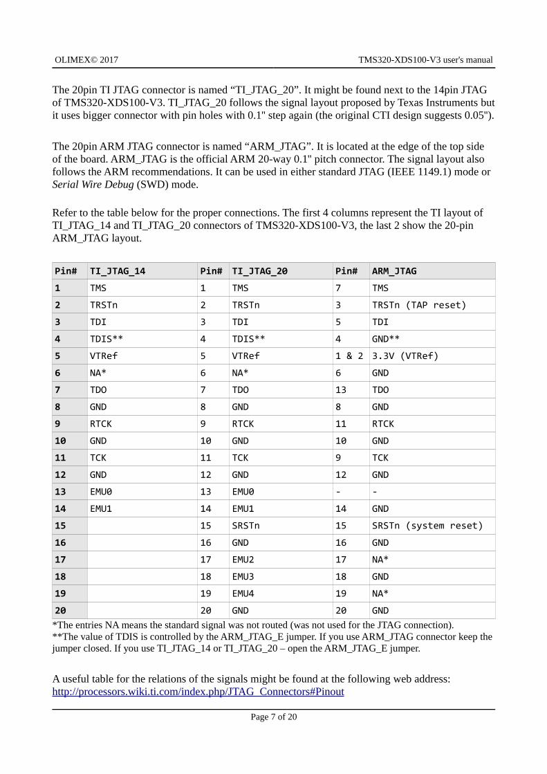
The 20pin TI JTAG connector is named “TI_JTAG_20”. It might be found next to the 14pin JTAG of TMS320-XDS100-V3. TI_JTAG_20 follows the signal layout proposed by Texas Instruments butit uses bigger connector with pin holes with 0.1'' step again (the original CTI design suggests 0.05'').
The 20pin ARM JTAG connector is named “ARM_JTAG”. It is located at the edge of the top side of the board. ARM_JTAG is the official ARM 20-way 0.1'' pitch connector. The signal layout also follows the ARM recommendations. It can be used in either standard JTAG (IEEE 1149.1) mode or Serial Wire Debug (SWD) mode.
Refer to the table below for the proper connections. The first 4 columns represent the TI layout of TI_JTAG_14 and TI_JTAG_20 connectors of TMS320-XDS100-V3, the last 2 show the 20-pin ARM_JTAG layout.
Pin# TI_JTAG_14 Pin# TI_JTAG_20 Pin# ARM_JTAG
1 TMS 1 TMS 7 TMS
2 TRSTn 2 TRSTn 3 TRSTn (TAP reset)
3 TDI 3 TDI 5 TDI
4 TDIS** 4 TDIS** 4 GND**
5 VTRef 5 VTRef 1 & 2 3.3V (VTRef)
6 NA* 6 NA* 6 GND
7 TDO 7 TDO 13 TDO
8 GND 8 GND 8 GND
9 RTCK 9 RTCK 11 RTCK
10 GND 10 GND 10 GND
11 TCK 11 TCK 9 TCK
12 GND 12 GND 12 GND
13 EMU0 13 EMU0 - -
14 EMU1 14 EMU1 14 GND
15 15 SRSTn 15 SRSTn (system reset)
16 16 GND 16 GND
17 17 EMU2 17 NA*
18 18 EMU3 18 GND
19 19 EMU4 19 NA*
20 20 GND 20 GND*The entries NA means the standard signal was not routed (was not used for the JTAG connection).**The value of TDIS is controlled by the ARM_JTAG_E jumper. If you use ARM_JTAG connector keep thejumper closed. If you use TI_JTAG_14 or TI_JTAG_20 – open the ARM_JTAG_E jumper.
A useful table for the relations of the signals might be found at the following web address: http://processors.wiki.ti.com/index.php/JTAG_Connectors#Pinout
Page 7 of 20

OLIMEX© 2017 TMS320-XDS100-V3 user's manual
2.4 Powering the board and installation procedure for CCS v5 and CCS v6
The XDS100v3 board is powered via the mini USB.
A. Install Code Composer Studio 5.1.x (or newer) before connecting XDS100 USB hardware.
B. Install the EmuPack with XDS100v3 support. It is usually downloaded via the update button.
C. Connect the XDS100 hardware
1. Make sure the Code Composer Studio v5.1.x (or newer) and EmuPack with XDS100v3 support is installed FIRST before plugging in the XDS100 HW to the PC.2. Connect USB cable from the PC to the XDS100 hardware. Connect the JTAG to the target board (be careful to plug it in correctly: pin 1 should go to pin 1. Red strip usually indicates the side of pin 1)3. You will notice small popups to inform user that USB hardware is recognized and installed correctly. No input are required.
D. Setup Code Composer Studio v5.1.x
4. Start Code Composer Studio and create a new target configuration.5. Select XDS100v3 as connection type6. Select device (target).
E. The configuration of the emulator in CCS v5.1.x is shown below (the one in CCS v6 is quite similar):
Page 8 of 20

OLIMEX© 2017 TMS320-XDS100-V3 user's manual
2.5 Powering the board and installation procedure for IAR EW for ARM 6
A. Install IAR EW for ARM (version 6.40 or newer) before connecting XDS100 USB hardware.
B. Connect the TMS320-XDS100-V3 to the mini USB of a computer.
C. Install the drivers for XDS100v3 hardware – there is an executable typically located in “C:\Program Files (x86)\IAR Systems\Embedded Workbench for ARM 6\arm\drivers\ti-xds”
D. Load a demo project and right-click over the project in the “Workspace” window. Select “Options” and click the “Debugger” group then choose “TI XDS100” from the drop-down menu. Then in the tab under the “Debugger” group go to “TI XDS100” and from the emulator menu select“TI XDS100v3 USB Emulator”.
E. You are now ready to debug your project!
Page 9 of 20

OLIMEX© 2017 TMS320-XDS100-V3 user's manual
CHAPTER 3 TMS320-XDS100-V3 DESCRIPTION
3. Introduction to the chapter
Here you get acquainted with the main parts of the board. Note the names used on the board differ from the names used to describe them. For the actual names check the TMS320-XDS100-V3 board itself.
3.1 Layout (top view)
Page 10 of 20

OLIMEX© 2017 TMS320-XDS100-V3 user's manual
3.2 Connectors
TI_JTAG_14 and TI_JTAG_20 are generally used with TMS targets and ARM_JTAG connector is used for TI ARM targets. If using wires to establish connection make sure that you use the proper system reset line T_SRST_N = SRST = nSRST = nRESET.
Page 11 of 20

OLIMEX© 2017 TMS320-XDS100-V3 user's manual
CHAPTER 4 INTERFACES AND HARDWARE
4. Introduction to the chapter
In this chapter the connectors function will be pointed, the meaning of the LEDs states will be explained, and the function of the jumpers would be clarified.
4.1 JTAG connectors
There are four JTAG connectors on this board. Each of them has 0.1'' step between pins. They are inthe sub-chapters below.
4.1.1 JTAG
The JTAG connector (note the one WITHOUT any prefix or suffix to the name) is used during production to upload the firmware of TMS320-XDS100-V3. It has a 14-pin TI JTAG layout.
You can not program targets using this connector! It is used to program the emulator itself!
It can be used to restore the firmware of the unit. The firmware is located inside the FPGA integrated circuit.
4.1.2 TI_JTAG_14
Used for 14-pin TI JTAG connection. The TI_JTAG_14 follows the JTAG layout of Texas Instruments. This interface might be used to communicate with Olimex TMS320-P28016 and Olimex TMX320-P28027. The interface might be used with any target that follows the 14-pin TI JTAG layout.
Jumper ARM_JTAG_E has to be open to be able to use TI_JTAG_14 successfully!
4.1.3 TI_JTAG_20
Used for 20-pin TI JTAG connection. The TI_JTAG_20 follows the JTAG layout of Texas Instruments. Note that the step is different from the original TI JTAG connector. The original connector has a 0.05'' step connector, while the one used by Olimex has 0.1''. The interface might beused with any target that follows the 20-pin TI JTAG layout.
Jumper ARM_JTAG_E has to be open to be able to use TI_JTAG_20 successfully!
4.1.4 ARM_JTAG_20
ARM_JTAG_20 connector was added in hardware revision C. It is used for 20-pin ARM JTAG connection. The interface might be used with any TI target that follows the 20-pin ARM JTAG layout. For example, boards like “Stellaris EKS-LM3S3748” can be debugged externally only using tools with ARM JTAG layout.
Jumper ARM_JTAG_E has to be closed to be able use ARM_JTAG_20 successfully!
Page 12 of 20

OLIMEX© 2017 TMS320-XDS100-V3 user's manual
4.2 USB mini
Standard USB mini cable connector. Used to connect the emulator to a personal computer.
4.3 Test pads
There are six testpads provided (CTS; RXD; GND; RTS; RXD; 3.3V). They allow access to the FTDI chip of the board. These are typically used for debugging purposes. In certain cases these can also be used for direct communication with the FT2232HL IC. The names are easily visible near each pad.
IMPORTANT! The signals routed to these pads are not free, they are also connected to the FPGA chip. Before using the test pads inspect the schematic, and consider that some of these signals may be already set as either inputs or outputs and their state is handled by the FPGA! You might damage the board if you fail to recognize that!
4.4 LEDs
There are four LEDs on TMS320-XDS100v3. Two for indicating power input and power output andtwo for the current board-mode.
4.4.1 Power LEDs
The PWR_LED shows whether the board is powered. The PWR_EN shows whether the board can power the target.
4.4.2 LED D3
The D3 LED shows the external header mode, it depends on the state of J4 jumper. By default J4 is open, external header mode disabled, and LED D3 is off. Refer to the chapter describing J4 below.
4.4.3 LED D4
LED D4 indicates when operating in an advanced (2 pin) scan format – cJTAG. This is determined by the hardware connections between XDS100v3 and the target board, and controlled by the software. During regular operation, it is typically off.
4.5 Jumpers
There are three PTH jumpers on TMS320-XDS100-V3: J4, J5, and ARM_JTAG_E.
4.5.1 Jumper J4
The unit can be used as an 1149.7 converter for an existing emulator. This has been verified using external XDS560 emulator. The external emulator must be aware of the programming and operational characteristics of the XSD100v3 adapter. To enable the external header, the jumper J4 must be closed. This will also cause LED D3 to illuminate.
For general use of the TMS320-XDS100-V3 as emulator and debugger, keep jumper J4 open. If youwant to use the unit as adapter for another unit, close J4.
Page 13 of 20

OLIMEX© 2017 TMS320-XDS100-V3 user's manual
4.5.2 Jumper J5
By default J5 is open (disconnected) and this way the signal UART_en_n is connected to 3.3V (via a resistor). If you close the jumper, UART_en_n would be connected to GND instead.
For general use of the TMS320-XDS100-V3 as emulator and debugger, keep jumper J5 open.
4.5.3 Jumper ARM_JTAG_E
The value of pin 4 (signal “TDIS”) of every JTAG interface is controlled by ARM_JTAG_E jumper.
Important:
In the Texas JTAG layouts TDIS is used to detect when the target is disconnected from the emulator. It is usually a pull-up in the emulator and GND on the target. The emulator senses the removal of GND. If you use TI_JTAG_14 or TI_JTAG_20 – open the ARM_JTAG_E jumper.
Pin 4 needs to be pulled-down in the ARM JTAG layout. If you use ARM_JTAG connector keep thejumper closed.
Page 14 of 20

OLIMEX© 2017 TMS320-XDS100-V3 user's manual
CHAPTER 5 FAQ
Q: I have an ARM chip but I can't establish connection in CCS. Where is the problem?
A: There might be a lot of reasons. However, always inspect the hardware connections first – make sure that you are using the proper connector. Try with ARM_JTAG connector (do not confuse ARM_JTAG with JTAG connector these are different).
Make sure that ARM_JTAG_E jumper is closed.
Make sure the hardware connections are properly established – especially make sure that you are using the proper system reset line (SRST = nSRST = nRESET is a mandatory signal – it is pin #15 of the ARM_JTAG connector; do not confuse it with pin #3 which is the optional TRST = nTRST).
Q: Does your design follow the original XDS100v3 design? If it doesn't what are the differences?
A: The TMS320-XDS100-V3 follows almost blindly most of the XDS100v3 reference design suggested by Texas Instruments. The main differences are that we provide extra connectors for both TI JTAG and ARM JTAG layouts; and we don't use the 20-pin compact TI headers and connector; we use 20 pin 0.1 inch pitch connectors (which are not standard according to the TI's JTAG standard; but easier to work with). You can always use jumper wires with the 0.1" pitch connectors, which is not the case with the 20-pin CTI connector.
Q: I connected the emulator to my computer but it requires drivers. Where can I find the drivers?
A: The drivers are installed via Code Composer Studio. Refer to the XDS100 wiki article for detailed instructions: http://processors.wiki.ti.com/index.php/XDS100
Q: Can I use the emulator with SmartRF Flash Programmer 2?
A: Yes. It had been tested successfully with SmartRF Flash Programmer 2 version 1.7.2 (build #5) and CC2650.
In case you get the following error - "The selected device was not recognized. Name of the device not defined in device_info.xml XDS100 Ver 3.0" - this is caused because the name of the Olimex emulator is "XDS100 Ver 3.0" while the definition in the programmer software is "XDS100v3". You can fix the error by editing the device_info.xml file containing name definitions. It is typically located in "C:\Program Files (x86)\Texas Instruments\SmartRF Tools\Flash Programmer 2\config\xml". Open device_info.xml with a text editor and search for the part where XDS100v3 definitions are (they follow the same pattern as below). Copy-paste the below code in the xml file and save. Then re-start the SmartRF Flash Programmer. The definition to add looks like:
<DeviceFamily type="eb" name="XDS"><Device name="default" family="XDS"><UsbController>XDS100V3-FTDI</UsbController><DeviceImage>serial_port.png</DeviceImage>
Page 15 of 20

OLIMEX© 2017 TMS320-XDS100-V3 user's manual
</Device><Device name="XDS100 Ver 3.0" family="XDS"></Device></DeviceFamily>
Refer to this picture on how the edited xml should look like this: https://www.olimex.com/Products/DSP/Emulators/TMS320-XDS100-V3/resources/xds100v3-olimex-smartrf2.jpg
Q: Do you manufacture and sell 14-pin and 20-pin CTI adapters?
A: No.
Q: Is it possible to use multiple units on the same system?
A: Yes. Each unit comes with a unique randomly generated serial number. To identify multiple devices use xds100serial.exe that can be found inside CCS folders (typically in C:\ti\ccsv6\ccs_base\common\uscif).
Q: I want to use multiple units on the same system but they seem to have identical serial number. What should I do?
A: The serial number is set in the FTDI chip. You can use the software tools provided by FTDI to modify any info inside, including the serial number. We have used FTDI's FTProg tool to set the default values. It is recommended to change only the serial number and refrain from changing other information. IMPORTANT! Be careful when changing the values. Changing the VID and PID of the devices would make the device undiscoverable by software tools and you would also have to edit the drivers in order to fit the new VID and PID. In case something goes wrong you can use the original XML file released by Texas Instruments to restore the FTDI firmware. It is located in this archive: http://processors.wiki.ti.com/images/d/d9/XDS100v2.zip
Page 16 of 20

OLIMEX© 2017 TMS320-XDS100-V3 user's manual
CHAPTER 6 REVISION HISTORY AND SUPPORT
6. Introduction to the chapter
In this chapter you will find the current and the previous version of the document you are reading. Also the web-page for your device is listed. Be sure to check it after a purchase for the latest available updates and examples.
6.1 Document revision
Revision Changes Modified page#
A, 10.09.12 Initial creation All
B, 25.09.12Fixed several problems with links. Fixed the line numbers and the formatting of the index. Some other minor changes.
3, 6, 7, 9, 12
C, 03.01.12Added emulator options screenshot, fixed several spelling errors 7
D, 21.11.13Added information about the layout of the JTAG interfaces 5
E, 29.01.14 Added information about the added ARM JTAG adapter 4, 6, 8
F, 23.03.15 Major documentation adjustments to fit hardware revision C
All
G, 08.07.16 Added FAQ section 13
H, 27.01.17 Added info about changing the serial 15
I, 06.10.17 Fixed information about D3, D4, J4, and J5 13, 14
Page 17 of 20

OLIMEX© 2017 TMS320-XDS100-V3 user's manual
6.2 Hardware revision
Remember to check the schematics and the board design files to compare the differences.
Board revision Notable changes
A Initial release of the board.
B
1. Added 4 holes at the board's corners, 3.3mm each. These can be used for rubber feet. Also can be used for embedding.
2. Added test pads for RXD, TXD, RTS, CTS, GND, 3.3V
3. Added adapter for standard 20-pin ARM JTAG layout
C
1. Removed the adapter for 20-pin ARM JTAG and added new dedicated 20-pin 0.1-inch ARM JTAG connectors
2. Added jumper ARM_JTAG_E that allows to switch between ARM JTAG layout and TEXAS JTAG layout.
3. The board's length increased from 3.75 inch to 4.15 inch to fit the new connector
4. Changed the printed name of the board to TMS320-XDS100V3+
5. Changed the printed hardware revision to “Rev.C”
6. Updated the names of the connectors to represent the difference between TI and ARM layout better
7. Updated the printed web-site link
Page 18 of 20
OLIMEX© 2017 TMS320-XDS100-V3 user's manual
6.3 Useful web links and purchase codes
The web page you can visit for more info on your device is https://www.olimex.com/Products/DSP/Emulators/TMS320-XDS100-V3/.
ORDER CODES:
TMS320-XDS100-V3 – completely assembled and tested JTAG emulator
How to purchase?
You can purchase directly from our online shop or from any of our distributors. Note that usually it might be faster and cheaper to purchase Olimex products from our distributors. List of confirmed Olimex LTD distributors and resellers: https://www.olimex.com/Distributors.
Please visit https://www.olimex.com/ for more info.
Page 19 of 20

OLIMEX© 2017 TMS320-XDS100-V3 user's manual
6.4 Product support
For product support, hardware information and error reports mail to: [email protected]. All document or hardware feedback is welcome. Note that we are primarily a hardware company and our software support is limited. Please consider reading the paragraph below about the warranty of Olimex products.
All goods are checked before they are sent out. In the unlikely event that goods are faulty, they must be returned, to OLIMEX at the address listed on your order invoice.
OLIMEX will not accept goods that have clearly been used more than the amount needed to
evaluate their functionality.
If the goods are found to be in working condition, and the lack of functionality is a result of
lack of knowledge on the customers part, no refund will be made, but the goods will be returned
to the user at their expense.
All returns must be authorized by an RMA Number. Email [email protected] for authorization
number before shipping back any merchandise. Please include your name, phone number and order
number in your email request.
Returns for any unaffected development board, programmer, tools, and cables permitted within 7
days from the date of receipt of merchandise. After such time, all sales are considered final.
Returns of incorrect ordered items are allowed subject to a 10% restocking fee. What is
unaffected? If you hooked it to power, you affected it. To be clear, this includes items that
have been soldered to, or have had their firmware changed. Because of the nature of the
products we deal with (prototyping electronic tools) we cannot allow returns of items that have
been programmed, powered up, or otherwise changed post shipment from our warehouse.
All returned merchandise must be in its original mint and clean condition. Returns on damaged,
scratched, programmed, burnt, or otherwise 'played with' merchandise will not be accepted.
All returns must include all the factory accessories which come with the item. This includes
any In-Circuit-Serial-Programming cables, anti-static packing, boxes, etc.
With your return, enclose your PO#. Also include a brief letter of explanation of why the
merchandise is being returned and state your request for either a refund or an exchange.
Include the authorization number on this letter, and on the outside of the shipping box.
Please note: It is your responsibility to ensure that returned goods reach us. Please use a
reliable form of shipping. If we do not receive your package we will not be held liable.
Shipping and handling charges are not refundable. We are not responsible for any shipping
charges of merchandise being returned to us or returning working items to you.
The full text might be found at https://www.olimex.com/wiki/GTC#Warranty for future reference.
Page 20 of 20