Embed Size (px)
Citation preview

TMQ Bosun - AP9
(AP9V 5 Rev 1)
OPERATION AND INSTALLATION MANUAL

Contents
....................................................................................................................... 4 INTRODUCTION ................................................................................................................ 5
Warning .................................................................................................................. 5 Overview ................................................................................................................. 5
AUTOPILOT OPERATION - STANDARD ................................................................................... 7 Standby ................................................................................................................... 9 Auto ......................................................................................................................... 9 Power Steering Mode ........................................................................................... 11 GPS Mode ............................................................................................................. 11 Watch Timer Mode ............................................................................................... 14 Commercial Boat Watch Timer ............................................................................ 15
CONTROLS ................................................................................................................... 16 Rate-of-Turn ......................................................................................................... 16 Weather (Heading Sensitivity) ............................................................................. 17 Counter-Rudder .................................................................................................... 17 Trim ...................................................................................................................... 18 Rudder Limit ......................................................................................................... 19 Rudder Control (Rudder Ratio) ............................................................................ 19
AUTOPILOT OPERATION- REMOTE CONTROL ....................................................................... 21 Hand Remote Power Steer ................................................................................... 22 Steering Lever & Electric Helm Steering ............................................................ 23
AUTOPILOT INSTALLATION ............................................................................................... 24 List of Components ............................................................................................... 25 Installation of Main Control Unit ......................................................................... 27
COMPASS INSTALLATION .................................................................................................. 27 Installing a Compass-Top Sensor ......................................................................... 28 Installing a Magnetic Sensor Unit (Fluxgate Compass) ...................................... 29 TMQ Fluxgate Compass Mounting Options ........................................................ 30 Interchanging Magnetic Sensor Unit & Compass Top Sensor ............................. 31
RUDDER FEEDBACK INSTALLATION ................................................................................... 33 Precautions ........................................................................................................... 33 Mounting .............................................................................................................. 34 Selection Switch- Standard or Heavy Duty Feedback .......................................... 36 Heavy Duty Rudder Feedback Installation Diagram ........................................... 37 Standard Rudder Feedback Installation Diagram ............................................... 38
INSTALLATION OF REMOTE UNITS ..................................................................................... 39
TMQ Bosun Autopilot (AP9V5.1) Page 3 of 71 8/03/2011

NMEA CONNECTION .................................................................................................... 42 NMEA Terminal Strip T6 - Pin Configuration ..................................................... 42 GPS Data Input .................................................................................................... 42 GPS Data Input Connection ................................................................................. 43 TMQ C-Plot Data Input Connection .................................................................... 43 TMQ Remote Display Connection ....................................................................... 44
HEADING DATA CONNECTIONS ......................................................................................... 44 Heading Data Output ........................................................................................... 44 Heading Data Input .............................................................................................. 44
EXTERNAL ALARM INSTALLATION ..................................................................................... 47 EXAMPLES - DRIVE CONNECTION DIAGRAMS ..................................................................... 48 GENERAL INFORMATION - DRIVE UNITS ............................................................................ 49 COMMISSIONING CHECKS ................................................................................................ 51
Post Installation Checks ....................................................................................... 51 Pre Sailing Dockside Tests ................................................................................... 51 Sea Trials .............................................................................................................. 53
RUDDER LIMIT ADJUSTMENT ........................................................................................... 55 Internal Rudder Limits .......................................................................................... 55 Setting/Resetting Rudder Limit ............................................................................. 56
COMPASS CALIBRATION ................................................................................................... 57 SPECIAL MODES ........................................................................................................... 59 OPTIONAL EXTRAS ......................................................................................................... 63 PCB OVERLAY ............................................................................................................ 67 SCHEMATIC DIAGRAM .................................................................................................... 68 DECLARATION OF CONFORMITY ........................................................................................ 69 WARRANTY ................................................................................................................... 70
TMQ Bosun Autopilot (AP9V5.1) Page 4 of 71 8/03/2011

Introduction
Warning
AUTOMATIC PILOTS ARE DESIGNED TO BE A NAVIGATIONAL AID AND SHOULD NEVER BE LEFT SOLELY IN CHARGE OF THE VESSEL. AN ADEQUATE WATCH SHOULD BE MAINTAINED AT ALL TIMES.
IT IS RECOMMENDED THAT THE AUTOPILOT NOT BE USED WHILE NAVIGATING IN RESTRICTED WATERWAYS AS WATER CURRENTS, WIND CHANGES OR RADIO TRANSMITTER INTERFERENCE MAY AFFECT VESSEL COURSE SUFFICIENTLY TO ENDANGER YOUR OWN OR OTHER VESSELS.
Overview
The TMQ Bosun (AP9) autopilot is a hybrid of digital and analogue technology to give the best features - excellent steering characteristics with digital compass display, keypad course input, GPS and gyro interfaces and manual controls for adjusting parameters to suit any boat.
The AP9 system comprises the following essential components:• Control Unit• Compass or Compass Top Sensor• Rudder Feedback Unit• Rudder drive system
Optional Components:• Hand or active Remote
TMQ Bosun Autopilot (AP9V5.1) Page 5 of 71 8/03/2011
• Second remote control display• Steering lever or electric helm• Rudder angle indicator• External alarm
The autopilot can control movement of the rudder through a mechanical drive motor, reversing hydraulic pump, solenoid valves on a constant running pump or relays. The motor outputs have been carefully designed to work with a wide range of motors; for more information on drive units, consult your dealer or TMQ Electronics.
• The autopilot unit should be installed out of direct sunlight and protected from water and spray.
• The compass must be installed in a place free of magnetic interference and connected to the autopilot.
• The rudder feedback must be attached to the rudder in such a way that it can accurately measure the position of the ships rudder and is also connected to the autopilot.
Provision has been made for either hand remote, steering lever or electric helm stations. Extra control devices may be connected to the internal connector strip. The special remote mode of operation may have to be adjusted for the various control devices.
For more information on using your AP9 autopilot, see the Autopilot Operation section of this manual.
For more information on installation of your AP9 autopilot, see the Autopilot Installation section of this manual
TMQ Bosun Autopilot (AP9V5.1) Page 6 of 71 8/03/2011

Autopilot Operation - Standard
The following is a brief overview of the capabilities of the Bosun autopilot. Each is described in more detail in following pages.
Note: Power to the autopilot is supplied via the Weather control. Turn the knob control in a clockwise direction to apply power to the Bosun; this will initially put the pilot into Standby mode.
If the option of electric wheel is enabled, this mode may not be available and the unit will go direct to power steer on turn on.
• Standby ModeThe digital display shows the current magnetic heading.The autopilot will not apply any steering control.
• Auto ModeThe autopilot will maintain your boat on the selected magnetic course. Course can be set via the keypad panel, changed by rotating the large knob or recalled from a stored course with the PRESET button. Where fitted the course can also be controlled via a remote control unit.
• Power SteerThe rudder angle may be controlled by the large control knob on the main panel or from one of the remote steering stations.
• GPS ModeWhen receiving information from a GPS unit, the autopilot can steer a vessel along a preset track to a precise latitude and longitude.
TMQ Bosun Autopilot (AP9V5.1) Page 7 of 71 8/03/2011

• Watch Timer A timer can be set for 1 to 120 minutes. When the time expires, an alarm sounds. Uses include timing of trawling runs or a reminder to check for anchor drag at set periods.
• Commercial Watch TimerFor vessels under survey. The timer can be set to give a warning alarm at a fixed preset time and provide an output control signal for a loud external alarm 1 minute after the internal alarm sounds.(Note: External alarm piezo siren must be fitted)
• Remote steering stationsTwo remotes may be fitted (eg: on each side of the bridge) allowing adjustment of the autopilot course or direct control of the rudder (power steering). An optional third steering lever may be connected to the control unit (subject to special order at time of delivery).
TMQ Bosun Autopilot (AP9V5.1) Page 8 of 71 8/03/2011
Standby
• WEATHER control turned clockwise to switch pilot on• The MAIN and STANDBY lights are on• The motor clutch is disengaged• No steering control output is generated• The commercial watch alarm is turned off (if enabled)• Watch alarm may be set (if required)• The digital display shows the vessels current magnetic course• Hand remote or steering lever (if installed) is ignored at first turn
on (except when special mode set *)• Other special remote modes are accessible (refer later in manual)
Possible alarms• Stopwatch timer alarm (if set)
* Note: If the option of electric steering is enabled, standby mode may not be available and the unit will go direct to power steer on turn on.
Auto
Engaging Auto steering mode
• Press AUTO button• A beep will sound• AUTO light is on• Pilot is “locked’ to course showing on the display• Steering control is generated• Rudder can be driven to the limit set position• Waypoint steering can be activated (if GPS fitted)• Watch alarm can be activated
TMQ Bosun Autopilot (AP9V5.1) Page 9 of 71 8/03/2011

Disengaging the Autopilot
• Press STANDBY button• A beep will sound• AUTO light is off• STANDBY light is on• Display shows boat heading• Boat under manual steering control (helm)
Course Adjustment in AUTO
• Rotate large control knob• Boat will change course in required direction• Course will change by 1º for each “click” of the knob• Display will change to indicate the new course• Press the red arrow button to change course to port• Pilot will change course to port by 1º for each button press• Press green arrow button• Pilot will change course to starboard by 1º for each button press• Display will change to indicate the new course• Enter a course by pressing keypad numbers (eg: 350)• Press GOTO• Pilot will steer boat to course 350º• Display will show 350
Possible alarm• Off course (more than 045º) or amount of off course set• Watch alarm (if set)
TMQ Bosun Autopilot (AP9V5.1) Page 10 of 71 8/03/2011

Power Steering Mode
Engaging Power Steering Mode
• Press POWER button• A beep will sound• Power light will be lit• Pilot will move rudder to centre position (midships)• Steer boat by rotating large control knob• Pilot can move rudder to the limit set• Amount of rudder applied depends on amount of knob rotation• Steer by using remote control (if fitted) when selected
Notes:1. There are many variations on power-steering with a remote unit
(eg: Electric Wheel or Steering Levers). Refer to your dealer or TMQ Electronics. Some information is available in the diagrams detailing remote unit operation and connections on pages 20 and 43
2. If your vessel requires counter-rudder* while steering in auto mode, you may wish to set the counter rudder control to "1" (ie: disabled) while using power-steer.* Refer to Counter Rudder settings on page 16
GPS Mode
Autopilot must be interfaced to a GPS generating NMEA 0183 data output. A route has to be selected on the GPS (refer GPS manual).
TMQ Bosun Autopilot (AP9V5.1) Page 11 of 71 8/03/2011
Engaging GPS Mode
• From any mode press GPS button• A beep will sound• GPS light will be lit• Display changes to course to steer (BTW on GPS)• Boat may change course to take up the new course (maximum rate of
turn is 10º per second or as set by RATE OF TURN knob - page 15)
Disengaging GPS Mode
• Press AUTO button to return pilot to auto mode• Press STANDBY button to return pilot to standby mode• Press POWER button to return pilot to power steer mode
If no GPS data or AP9 does not receive the data
• Autopilot maintains the current course• No GPS alarm will sound• GPS light will flash
Setting up your GPS unit
Consult your GPS manual for this procedure first. Because there are a great variety of GPS units that work with this autopilot, the following is a guide only.
a) GPS must output NMEA 0183 datab) Data must include at least one of the following sentences:
(i) APA (ii) APB(iii) BOD and XTE.
TMQ Bosun Autopilot (AP9V5.1) Page 12 of 71 8/03/2011
• Set up route in GPS• Set arrival zone • Select “auto sequence” if more than one waypoint en route• For XTE output only from GPS steer boat to course before
engaging GPS on pilot.
Remember: Prior to engaging GPS you must program a route into the GPS for the autopilot to follow
Note: The bearings generated by the GPS unit must correspond to the bearings the autopilot is receiving from its magnetic compass. The greater the difference between these bearings, the less accurate the GPS Mode steering will be.
• Ensure that the GPS unit has the correct magnetic correctionfactor.
• Ensure that the autopilot compass is correctly installed and aligned.
TMQ Bosun Autopilot (AP9V5.1) Page 13 of 71 8/03/2011

Watch Timer Mode
To set standard watch timer• Enter a value between 001 and 120 via keypad (eg: 010)• Display reads 010 (10 minutes)• Press TIMER button• Timer light will be lit• Display reverts to course heading• After 10 minutes elapses timer alarm will sound• Timer light flashes• Press TIMER button to reset time
To reset watch timer when alarm sounds• When the time set has elapsed the timer alarm will sound• Timer light flashes• Press TIMER button to reset time• Timer will recommence counting down from time set
Note: If an external alarm is fitted this will sound 1 minute after the internal alarm if the timer has not been reset or muted
To disable (mute) watch timer • Enter 000 via keypad• Display shows 000• Press TIMER button• Timer light will be off
TMQ Bosun Autopilot (AP9V5.1) Page 14 of 71 8/03/2011

Commercial Boat Watch Timer
Used where survey regulations for commercial vessels require a watch timer (which includes an external alarm) fitted with an autopilot.
NOTE: Once the commercial watch alarm has been enabled, it cannot be disabled by the user.
To enable the commercial watch timer alarm• When pilot is on press STANDBY button• Both standby and main lights will be on• Enter 906 via keypad• Display reads 906• Press and hold down STANDBY button• Press GOTO button• Display will read A-0• Standby light is off• Main light is flashing• Rotate large knob until display reads A-1• Press GOTO button• Display reads 000• Rotate large knob until display reads required time (eg: 005)• Press GOTO button to remember time set • Press MAIN button to exit commercial watch alarm mode• Main light will be on• Standby light will be on• Display reverts to course heading.
TMQ Bosun Autopilot (AP9V5.1) Page 15 of 71 8/03/2011

When the commercial timer is enabled and the autopilot is in control of the boat (i.e: in AUTO, GPS or REMOTE AUTO mode), the AP9 internal alarm sounds after completion of the selected interval and the louder external alarm one minute later, unless the timer is previously reset.
In STANDBY, POWER STEER or remote POWER modes, the timer can be set to any required time as for standard watch alarm.
Controls
Rate-of-Turn
This control sets the rate-of-turn for the vessel, to prevent very sharp turns when changing course.When set fully anticlockwise, the boat will turn at a rate of 1º/second (i.e. 180 degrees in 3 minutes). When set fully clockwise, the boat will turn at a rate of 40º/ second (i.e. as fast as possible for most vessels).
The slower settings may be used for turns while trawling, trolling, etc., and the mid-range settings used to prevent dangerous or uncomfortably sharp turns. Note: The turn rate of a vessel will also depend upon the rudder ratio setting; it is also dependent on the rudder limits if the limit set is small.
If a course change is entered and it is realised that the rate-of-turn control is set too low (i.e. the turn is too slow), the rate of turn can be adjusted clockwise to increase the turning speed. Once a turn has begun, rate of turn can be increased but not decreased.
Rate of turn control only applied in AUTO or GPS modes of steering. A course change entered from a remote station is not affected by rate of turn.
TMQ Bosun Autopilot (AP9V5.1) Page 16 of 71 8/03/2011

Weather (Heading Sensitivity)
The main power switch is incorporated in this variable control. When in the OFF position no power is applied to the AP9. By turning the knob clockwise from the OFF position, the switch applies power to the Bosun.
This setting is also used for adjusting the autopilot response to varying sea conditions and varying vessel response capabilities. The weather value sets the heading sensitivity (sometimes known as dead band) which determines the accuracy of the vessel steering. A high weather setting will cause the vessel to steer very accurately but may cause excessive use of the steering.
In good weather, set this control to a relatively high value but at the same time ensure the drive lights do not flicker continuously. This will give the straightest possible course.
In poorer weather, this setting can be reduced (anticlockwise) to prevent over activation of the steering control.
Rotating the control fully anti-clockwise will turn off power to the Bosun autopilot.
Counter-Rudder
In some vessels, changing course requires a large amount of rudder to be applied initially and then a smaller amount of rudder in the REVERSE (counter) direction to stop the vessel from swinging beyond its desired course. This is called counter-rudder.
TMQ Bosun Autopilot (AP9V5.1) Page 17 of 71 8/03/2011

A counter-rudder setting of "1" gives no counter-rudder steering. This is normally suitable for light and manoeuvrable vessels. If you find your ship over-steering when under autopilot control, increase the counter-rudder setting by small amounts at a time to get the optimum steering.
Once the correct setting is found for your vessel, it should not need to be changed.
Trim
When the Bosun is first switched on and in STANDBY mode, the TRIM knob should initially be set in mid position, which corresponds to a setting of 5.There are circumstances in which the autopilot may set the rudder in the centre (according to its feedback unit), but the vessel does not steer straight ahead. Reasons for this are:
• The rudder feedback unit may not be correctly aligned• There may be a side-wind, current, net drag, etc., which causes the
vessel to steer to one side.
To find the correct trim setting:With the vessel travelling straight ahead, switch the autopilot to POWER STEER mode. Adjust the trim control until the ship steers straight.
The trim control is not intended to be used for adjusting the vessel course in auto or power steer mode.
TMQ Bosun Autopilot (AP9V5.1) Page 18 of 71 8/03/2011

Rudder Limit
There are physical limitations to the angle through which the rudder can move. If the autopilot attempts to drive the rudder past these limits, damage to the steering gear or autopilot drive system may occur.
Note: Internal rudder limits are pre set during installation to suit vessel requirements. These should not require resetting but should be checked when any changes are made to the steering gear.
An external control on the front panel of the Bosun can be used to limit the amount of rudder travel to a narrower angle or range. (In some special circumstances this control can be used to limit the rate of turn of the vessel). Under normal operation the external rudder limit control is set at maximum.
Rudder Control (Rudder Ratio)
This setting is used to determine the amount of rudder angle applied for a given angle off course (ie: the amount of rudder the vessel requires for good steering)
The centre position is suitable for most vessels, but should the steering be sensitive or slow, adjustment
maybe required. In general, a responsive vessel with a relatively large rudder or very small keel will require a small rudder setting. A large, slow vessel may require a high value for the rudder ratio.
TMQ Bosun Autopilot (AP9V5.1) Page 19 of 71 8/03/2011

This may also be adjusted according to speed - low speeds require more rudder angle for steering than high speeds.
• A value of "1" signifies the minimum amount of applied rudder (for sensitive steering, large rudders or low gearing ratio.)
• A value of "10" signifies the maximum amount of applied rudder (for vessels with slow steering, small rudders or high gear ratio).
When the rudder setting is too low, turns will take an excessive amount of time, and the vessel may "wander".
When the rudder setting is too high, turns will be rapid and the vessel will oversteer.
TMQ Bosun Autopilot (AP9V5.1) Page 20 of 71 8/03/2011
Autopilot Operation- Remote Control
The following is a brief overview of the capabilities of the AP9 autopilot with remote control units. Each is described in more detail later in the manual.
Hand remoteThe AP9 can be controlled with a hand remote unit. Auto and power steer modes can be selected. Special remote response mode r-1 must be set in AP9.
Steering Lever/Electric helmThe boat may be steered using a steering lever with the AP9. Special internal remote modes r-3, r-4, r-5 or r-6 must be set in AP9 depending on remote control connection (see pages 58 and 59)
Hand Remote Auto Steer(AP9 special mode set to r-1)
To engage auto steer mode with Hand Remote Unit
• Switch AP9 to STANDBY, AUTO or POWER STEER• Set remote knob to centre position• Switch remote switch to AUTO• Pilot locks on to boat heading as for normal autopilot• Change course by +/- 90 º by rotating knob
Note: If remote switch is already in the AUTO position, move switch to OFF and then back to AUTO .
TMQ Bosun Autopilot (AP9V5.1) Page 21 of 71 8/03/2011
To disengage auto steer mode with Remote Unit
• Switch remote switch to OFF• Pilot is now in STANDBY mode• Boat is now steered manually
To disengage remote auto steer mode with Main Control
• Select STANDBY, AUTO or POWER STEER on the AP9• Boat is now steered from the Main Control panel
Hand Remote Power Steer To engage power steer mode with Hand Remote
• Switch AP9 to STANDBY, AUTO or POWER STEER• Set hand remote knob to centre position• Switch remote switch to POWER STEER• Boat is in manual control• Steer boat by rotating knob
Note: If remote switch is already in the POWER STEER position, move switch to OFF and then back to POWER STEER
To disengage power steer mode with Remote Unit
• Return remote unit course knob to centre• Switch remote switch to OFF• Pilot is now in STANDBY mode• Boat is now steered manually using helm
TMQ Bosun Autopilot (AP9V5.1) Page 22 of 71 8/03/2011

To disengage remote power steer by Main Control
• Select STANDBY, AUTO or MAIN on AP9 main Control• Boat is now steered from the Main Control panel
Important!!
The remote unit course knob (or steering lever) must be returned to centre before leaving remote power steer mode. If not, auto mode or GPS mode will not steer accurately.
Steering Lever & Electric Helm Steering(AP9 must be set for the correct special remote mode - see page 58)
Steering Levers and Electric Helms provide full follow up steering. A steering lever or electric helm operates in a similar way to a hand remote control. However, the method of operation will depend on the special remote mode set.
To Engage Steering Lever or Electric Helm
• Press select switch (or toggle select switch)• Steer boat using lever or wheel
Note: Some internal remote mode settings allow for power steering at turn on, eg: Electric helm wired to Wheel input at T7 terminal clock
To disengage Steering Lever or Electric Helm
• Press select switch• Steer boat manually
TMQ Bosun Autopilot (AP9V5.1) Page 23 of 71 8/03/2011
Autopilot Installation
EMC Considerations & Precautions:-
All TMQ equipment and accessories are designed to the best industry standard for use in the marine environment. Their design and manufacture conforms to the appropriate Electromagnetic Compatibility (EMC) standards, but good installation is required to ensure that performance is not compromised.
Although every effort has been taken to ensure the autopilot will perform under all conditions, it is important to understand that some factors could affect the operation of the product.
Complete installation instructions are provided in this manual. Some preliminary suggestions follow:
Installation:-
To reduce the risk of operating problems, all TMQ equipment and cables connected to it should be at least 1 metre (3 feet) from any equipment transmitting or cables carrying radio signals, eg: VHF radios, cables and antennas. In the case of SSB radios, the distance should be increased to 2 metres (7 feet).
Genuine TMQ cables should be used at all times. Cutting and rejoining these cables could compromise EMC performance and should be avoided unless doing so is suggested in the installation instructions.
Position of electronic compass is important to ensure no magnetic interference. It may be necessary to trial several positions before deciding on an optimum position. Check other side of bulkhead, dash and/or
TMQ Bosun Autopilot (AP9V5.1) Page 24 of 71 8/03/2011

deckhead for any material which may interfere with the compass (steel or iron in particular). Keep electronic compass away from the boat’s magnetic compass.
Check:-
Always check the installation before going to sea to make sure that it is not affected by radio transmissions, engine starting, low battery voltage or other problems.
In some installations it may not be possible to prevent the equipment from being affected by external influences. Usually this will not damage the equipment but may lead to resetting of memory or momentary incorrect operation.
Interconnection:-
If your autopilot is to be connected to other navigational equipment using a cable not supplied by TMQ, a suppression ferrite MUST always be fitted to the cable close to the TMQ unit.
List of Components
The Bosun AP9 autopilot control system when packed has the following components:
• AP9 Main Control Panel – 2 metre power cable• Compass, Compass Top Sensor or Electronic Compass (depending
on model ordered) – 5m cable attached• Rudder Feedback Unit – Heavy Duty (RFUH)• Rudder feedback cable – 14 metre 3 core.• Rudder Linkage assembly• Owners manual, RFU mounting bracket, mounting screws
TMQ Bosun Autopilot (AP9V5.1) Page 25 of 71 8/03/2011

BEFORE INSTALLATION, ENSURE YOU HAVE PURCHASED THE CORRECT PARTS FOR YOUR VESSEL.
TMQ Autopilots are intended for use in three (3) basic configurations: 1. AP9 can be used to control most brands of solenoid control valves
(hydraulic). System components required:• Control unit• Compass• Rudder feedback unit
2. AP9 and mechanical drive system - used to drive most hand-operated mechanical steering systems eg: rod & chain, push-pull or pull-pull systems. Some helm pumps can also be used with a mechanical drive to provide an installation, which requires no additional hydraulic pump. System components required:• Control unit• Compass• Rudder feedback unit• Mechanical drive
3. AP9 and reversing hydraulic pump - used with hydraulic steering systems. Different pump units are used to cater for a wide range of systems. Correct installation is required and pump size and voltage should be considered BEFORE installing the hydraulic pump. System components required:• Control unit• Compass• Rudder feedback unit• Reversing hydraulic pump
TMQ Bosun Autopilot (AP9V5.1) Page 26 of 71 8/03/2011

Installation of Main Control Unit
Position & mounting
• Select a dry position• Provide access for wiring to rear of the pilot (minimum compass,
feedback, power and drive)• Provide a cut out section in the dash• Install control unit and fix with four screws• Route the power cable to 12 or 24 VDC power source• Check AP9 WEATHER switch is OFF • Connect power cable to the AP9
Note: To control the autopilot from a remote position, fit a remote unit. Wiring
• Keep autopilot connection cables away from radio aerials and cables
• Select a drive unit interconnection cable of appropriate size to prevent voltage drop
Compass Installation
There are three types of compass suitable for this autopilot - a compass-top sensor (CTSB), a magnetic sensor unit (TMQ Fluxgate Compass COMMAGB) or an electronic compass such as the Elproma NMEA compass (ECS1)
TMQ Bosun Autopilot (AP9V5.1) Page 27 of 71 8/03/2011

Installing a Compass-Top Sensor
A compass top sensor should be used as the pilot heading reference unit for steel boats. Before attaching the CTSB to the top of a flat top compass, ensure there are no defects in the compass, eg: sticking card, as this will affect the operation of the autopilot.
Position
• Firstly determine the correct position of the CTSB on the compass glass top (CTSB is central on the top and cable facing aft)
• Route the cable to the AP9 control unit position• Connect the cable into AP9 compass terminal strip• Before fixing the CTSB to the compass surface, switch on the AP9,
align the CTSB carefully so that the AP9 display reads the same as the boat magnetic compass
• When position is correct attach the CTSB with double sided tape
Wiring
The 5-wires & shield of the compass cable must be connected to the internal terminal strip labelled T3 Compass. The compass wiring colour code is marked next to each terminal. Ensure good contact is made between cable conductors and terminal strip connectors. If the compass cable requires extending, contact TMQ for extension cable.
TMQ Bosun Autopilot (AP9V5.1) Page 28 of 71 8/03/2011

Installing a Magnetic Sensor Unit (Fluxgate Compass)
Where there is magnetic interference on a vessel, the magnetic sensor unit may have to be tried in several positions to obtain the best operating results before final installation. Good autopilot course holding is dependent upon the compass being free form magnetic interference
Exercise care when handling the compass as internal gimbals may be damaged from abuse. Remove internal packing prior to installing.
Position
• Determine a suitable position free of magnetic influence• Ensure there are no radios or radio aerials or cables nearby• Check other side of bulkheads or behind dashes for any likely
interference• Install compass bracket vertically (on bulkhead, dash or deck head)• Carefully remove internal transit packing from compass• Insert compass body into bracket• Rotate compass in bracket until cable faces towards the stern• Route the cable to the AP9 Control unit position• Plug compass cable into AP9 autopilot• Check AP9 display reads the same as the boat compass when pilot
is switched on.
Note: The compass can be mounted outside the hull of the boat if required (eg: on a mast of a yacht). However, places to be avoided are low in the hull near an engine or machinery because of magnetic interference or too high up a mast because of potential heeling errors.
TMQ Bosun Autopilot (AP9V5.1) Page 29 of 71 8/03/2011
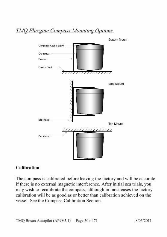
TMQ Fluxgate Compass Mounting Options
Calibration
The compass is calibrated before leaving the factory and will be accurate if there is no external magnetic interference. After initial sea trials, you may wish to recalibrate the compass, although in most cases the factory calibration will be as good as or better than calibration achieved on the vessel. See the Compass Calibration Section.
TMQ Bosun Autopilot (AP9V5.1) Page 30 of 71 8/03/2011

Interchanging Magnetic Sensor Unit & Compass Top Sensor
The magnetic sensor unit (fluxgate) and compass top sensor can be interchanged. However, the compass detector switches identified as component DIP2 on the PCB must be switched to correct position. (Note: Rear cover must be temporally removed to access the switches).
For magnetic sensor unit (COMMAG/ Fluxgate) switch 1 and 2 to OFFFor compass top sensor (CTS) switch 1 and 2 to ON
TMQ Bosun Autopilot (AP9V5.1) Page 31 of 71 8/03/2011

Installing an Electronic Compass – Elproma ECS1
Note: Refer to Elproma installation instructions. Mount away from any external magnetic interference, eg: radio or speakers. The compass must be mounted in a vertical position with the arrow (on the top of the case) pointing towards the bow of the boat.
Position
• Determine a suitable position free of magnetic influence• Ensure there are no radios or radio aerials or cables nearby• Check other side of bulkheads or behind dashes for any likely
interference• Install compass bracket vertically• Rotate compass in the bracket if necessary until the arrow faces the
bow of the boat• Route the cable to the AP9 control position• Connect the compass cable to the internal connection strip of the
AP9 marked T5 Remotes and T6 NMEA as follows:• Red wire to T5 10V• Black wire to T5 NEG• Brown wire to T6 NEG• Purple wire to T6 DATA 1• Link T5 NEG to T6 IN -• Blue wire to T6 IN +
TMQ Bosun Autopilot (AP9V5.1) Page 32 of 71 8/03/2011

Rudder Feedback Installation
Precautions
The rudder feedback unit is water resistant. However, if it is to be mounted in a wet position, some effort is necessary to ensure the unit does not become immersed in water. If necessary the standard rudder feedback unit may be mounted upside down, in which case the feedback cable may be cut in a suitably dry position, and the blue and red wires swapped.
DO NOT MOUNT THE HEAVY DUTY RUDDER FEEDBACK UNIT UPSIDE DOWN
NOTE: THE AUTOPILOT WILL NOT FUNCTION CORRECTLY IF A RUDDER FEEDBACK IS NOT FITTED, OR IF THE FEEDBACK IS FAULTY OR INCORRECTLY ADJUSTED.
NOTE: THE RUDDER FEEDBACK UNIT IS FACTORY ALIGNED. THE ARM SHOULD NOT BE REMOVED OR LOOSENED UNNECESSARILY. IF ARM IS LOOSENED OR REMOVED, VOLTAGE ALIGNMENT SHOULD BE CHECKED BEFORE USING THE AUTOPILOT. THIS MUST BE DONE BY A COMPETENT TECHNICIAN.
TMQ Bosun Autopilot (AP9V5.1) Page 33 of 71 8/03/2011

Mounting
Refer to the relevant installation diagrams on page 36 or 37 for the rudder feedback unit.
The rudder feedback unit is water resistant. However, if it is to be mounted in a wet position some protection will be necessary to ensure the unit does not become immersed in water.
Position
• Select a position adjacent to the tiller arm• Install the mounting bracket to accommodate the rudder feedback
unit with its arm parallel to and pointing in the same direction as the tiller
• Attach the rudder feedback to the bracket. (For RFUS arm is uppermost. For RFUH shaft is lowermost)
• Drill a hole in the tiller arm for the linkage arm connection block (1/4” diameter)
• Attach the linkage swivel block to the tiller• Attach the linkage ball joint to the rudder feedback arm• Fit the linkage arm through the swive block and attach the other
end to the ball joint• Remove the top of the feedback (RFUH only)• Connect 3 core cable to the RFU terminal strip (RFUH only)• Route the rudder feedback cable to the AP9 position• Connect the RFU cable to the internal terminal strip T2 marked
RFU of the AP9
TMQ Bosun Autopilot (AP9V5.1) Page 34 of 71 8/03/2011

Installation Checks
• Turn the helm slowly from hard over to hard over and observe the movement of the rudder feedback arm
• Ensure the feedback arm or linkage does not foul in any position• Ensure there is no strain on the feedback arm or linkage • Check the rectangular correlation between the feedback arm, the
tiller and the linkage with rudder amidships• Check direction of feedback arm movement (port and starboard)
corresponds with the markings on the feedback body• Check the feedback arm direction matches the tiller movement
direction for port and starboard
Note: Correct any problems before using the autopilot
TMQ Bosun Autopilot (AP9V5.1) Page 35 of 71 8/03/2011

Selection Switch- Standard or Heavy Duty Feedback
The AP9 is normally dispatched from the factory as ordered. However, when installation of the feedback is completed on the boat the RFUS / RFUH selection switch in the AP9 control unit should be checked for correct selection.
If RFUS is used, set DIP 1 Switch 1 and 2 to OFF. If RFUH is used, set DIP 1 Switch 1 and 2 to ON.
TMQ Bosun Autopilot (AP9V5.1) Page 36 of 71 8/03/2011
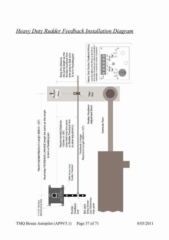
Heavy Duty Rudder Feedback Installation Diagram
TMQ Bosun Autopilot (AP9V5.1) Page 37 of 71 8/03/2011

Standard Rudder Feedback Installation Diagram
TMQ Bosun Autopilot (AP9V5.1) Page 38 of 71 8/03/2011

Installation of Remote Units
Hand and Active Remotes use a small clip bracket for mounting.
Steering Levers are normally mounted in-dash. For a TMQ steering lever this will require a 90mm hole to be cut for mounting plus a position for a push button election switch (if used). Other steering levers as required.
The units are very robust and either of these may be mounted where it is subject to occasional splashes of water. If mounted in direct sunlight, the decal may fade.
Hand Remote• Select a position for the Hand Remote bracket• Install the bracket and attach the remote• Route the cable to the AP9 control position• Connect the remote cable internally to T5 Remotes of AP9• When the AP9 is switched on, test the remote operation
Steering Lever (TMQ)• Select a position for the Steering Lever• Cut a 90mm clearance hole for mounting the Lever• Secure the steering lever with two screws• Fit selection switch adjacent to lever (if used)• Route the cable to the AP9 control position• Connect the cable internally to terminal strip T5 Remotes socket
(or terminal strip T7 Wheel depending on the special mode of operation set in the AP9)
TMQ Bosun Autopilot (AP9V5.1) Page 39 of 71 8/03/2011

Remotes Terminal Strip T5 Connections
Wiring colour code for Remote 1 input:
Blue NEG NegativeRed 5V + 5 Volts--------- SEL2 Remote 2 Logic Select Signal--------- WIP2 Remote 2 Trim Signal InputYellow SEL1 Remote 1 Logic Select SignalGreen WIP1 Remote 1 Trim Signal Input
Alternatively for Remote 2 input:
Blue NEG NegativeRed 5V + 5 VoltsYellow SEL2 Remote 2 Logic Select SignalGreen WIP2 Remote 2 Trim Signal Input-------- SEL1 Remote 1 Logic Select Signal-------- WIP1 Remote 1 Trim Signal Input
Remote Calibration.
The remotes can be calibrated if required; this allows the full range of the steering input to be used. Each remote fitted has to be calibrated
Calibration Procedure
• Switch AP9 to STANDBY• Enter 911 via keypad• Press and hold pressed the STANDBY button• Press GOTO button• REMOTE 1 and MAIN lights flash
TMQ Bosun Autopilot (AP9V5.1) Page 40 of 71 8/03/2011

• Display flashes rCL • Rotate remote control knob fully clockwise and anticlockwise • Press REMOTE 2 button• REMOTE 2 and MAIN lights flash• Rotate second remote control * knob fully in both directions • Press MAIN button to exit calibration and save the setting
Note: If the boat does not steer straight ahead when the remote control course knob is centred, the rudder feedback may need realignment.Caution: If the boat is carrying temporary “weather helm” as a result of sail trim or net drag, realignment may not be necessary. Check BEFORE realigning.
TMQ Bosun Autopilot (AP9V5.1) Page 41 of 71 8/03/2011

NMEA Connection
The internal terminal strip T6 NMEA allows for the following connections:
1. GPS data input – for waypoint or GPS steering
2. Heading data input – as heading reference
3. TMQ proprietary data input and output – data for TMQ remote display for example AP55 or AP60
Note: + 10 V for power to remote display is taken from T5
NMEA Terminal Strip T6 - Pin Configuration
Pin 1 – Heading data – output NEGPin 2 – Heading data + output DAT1Pin 3 – NMEA heading – input IN –Pin 4 – NMEA heading + input IN +Pin 5 – TMQ data – output NEGPin 6 – TMQ data + output DAT2Pin 7 – GPS data – input IN –Pin 8 – GPS data + input IN+
GPS Data Input
The AP9 pilot will accept two forms of GPS data in NMEA 0183 format as follows:
• GPS Plotter data – APA, APB or XTE + BOD for waypoint steering – pilot display shows BTW
TMQ Bosun Autopilot (AP9V5.1) Page 42 of 71 8/03/2011
• GPS data as heading reference – used when magnetic heading reference from a compass is not available – pilot display shows COG *
* Note: This is a special remote mode which has to be internally set
into the AP9 using a computer with Hyperterm program. Boat must be making more than 2 knots true speed over ground.
GPS Data Input Connection
Refer to GPS manual for correct identification of wires for data output connection. An example of GPS connection:
• GPS TX+ connect to AP9 IN+ (pin 1 T6 NMEA terminal block)• GPS TX- connect to AP9 In- (pin 2 T6 NMEA terminal block)
TMQ C-Plot Data Input Connection
The AP9 will accept data from a computer operation C-Plot program for waypoint steering. The connections are as follows:
• Pin 3 C-Plot Data Plug connects to AP9 IN+• Pin 5 C-Plot Data Plug connects to AP9 IN-
Displays shows bearing to waypoint - BTW
TMQ Bosun Autopilot (AP9V5.1) Page 43 of 71 8/03/2011

TMQ Remote Display Connection
When a TMQ remote display (AP55* or AP60) is used with the AP9, they are connected to T5 Remotes and T6 NMEA terminal blocks. Wiring colour code connections are as follows:
• Red ------- T5 Pin 1 ------- 10V• Green -----T6 Pin 4 ------- IN +• Blue -------T6 Pin 5 ------- NEG• Yellow --- T6 Pin 6 ------- DAT2
Link pins 3 and 5 on T6 (IN – to NEG)* Colour code applicable for display S/N 55872 or later
Heading Data Connections
Heading Data Output
Heading data output is available on the internal T6 connector strip. Heading sentences transmitted are HDM, HDT and HDGNote: Refer page 57 for more heading output information
Pin 7 DAT1 Heading data + output Pin 8 NEG Heading data - return
Heading Data Input
The AP9 pilot can accept NMEA 0183 heading data input from any source, for example, GPS compass or other electronic compass. Heading sentences accepted are HDT, HDM and HDG.
TMQ Bosun Autopilot (AP9V5.1) Page 44 of 71 8/03/2011
WiringHeading data input is connected via the internal terminal block T6 NMEA. Connections are:
Pin 4 T6 IN+ Heading + data inputPin 3 T6 IN- Heading – data input
TMQ is able to supply an electronic compass, Elproma ECS1, which will connect to the internal terminal strips T5 Remotes and T6 NMEA as follows:
ECS1 Wiring Colour Code
• Red ------------- T5 10V Pin 1 (positive power)• Black ----------- T5 NEG Pin 2 (negative power)____________________________________________________• Brown ---------- T6 NEG Pin 1 (calibration)• Purple ----------- T6 DAT1 Pin 2 (calibration)• Link T5 NEG -- T6 IN – Pin 3 (heading)• Blue --------------T6 IN + Pin 4 (heading)
Heading Data Priority
The AP9 will operate with both TMQ electronic compass (COMMAGB) and NMEA heading data input connected. The pilot will accept the NMEA heading data as first priority.
If the NMEA data is not present the AP9 will display the heading received from the standard compass (COMMAGB - if fitted).
TMQ Bosun Autopilot (AP9V5.1) Page 45 of 71 8/03/2011

If the NMEA data fails during operation, the unit will revert to the standard compass and the alarm will sound. The alarm can only be cancelled by turning the AP9 off and on again.
TMQ Bosun Autopilot (AP9V5.1) Page 46 of 71 8/03/2011

External Alarm Installation
For non survey vessels an external alarm is optional. For vessels needing the commercial watch alarm feature fitted for survey requirements, an external alarm is required in addition to the AP9 internal buzzer.
This alarm will sound if the timer alarm has been sounding for one minute without being reset and autopilot is NOT in SET mode.
A 12 volt piezo buzzer with current draw not exceeding 250 milliamps should be used (TMQ Part No. SIREN). If a siren or alarm unit is used which draws in excess of 250 milliamps, this should be connected via a relay.
The external alarm circuit is used to energise the siren direct. For larger units the circuit energises a relay coil with the siren being energised via the relay contacts.
To Install External Alarm Siren
• Mount SIREN in appropriate position for optimum effect (leads may have to be lengthened)
• Remove rear cover of AP9• Route siren wires through a rear cover gland• Connect SIREN + lead (red) to T4 Ext Al + terminal• Connect SIREN – lead (black) to T4 Ext Al - terminal• Replace AP9 cover
To enable the commercial watch alarm refer page 14.
NOTE: Once the commercial alarm is enabled, it cannot be
TMQ Bosun Autopilot (AP9V5.1) Page 47 of 71 8/03/2011

reverted. Examples - Drive Connection Diagrams
TMQ Bosun Autopilot (AP9V5.1) Page 48 of 71 8/03/2011

General Information - Drive Units
The AP9 autopilot is capable of controlling reversing hydraulic pumps, mechanical drives, linear hydraulic drive systems, linear mechanical systems, solenoid valves on constant running pumps and relays. When installing any drive system, refer to the manufacturers’ specifications and instructions. Follow all instructions.
Installation Considerations
Mechanical Drives • Ensure correct voltage of drive unit• Mount horizontally in a dry position• Ensure robust and stable mounting platform is available• Provide for cable connection to AP4 control unit• Provide access for drive sprocket and chain to be fitted• Provide for cable lay if linear mechanical drive• Check correct sprocket ratio for the boat
Hydraulic Pumps • Check correct pump voltage for boat• Ensure correct flow rate of pump matched for steering• Mount horizontally in a dry position• Pump should be mounted lower then the helm pump• Provide adequate space for hydraulic line connections• Ensure access to existing boat steering lines• A balance line must be connected from autopilot pump reservoir to
helm pump reservoir• Replace any vented bung on pump with non vented• Check if extra lock valve is needed for steering system• When mounted, fill with oil and purge air from system
TMQ Bosun Autopilot (AP9V5.1) Page 49 of 71 8/03/2011
Solenoid Valves
Links are provided to allow jog lever operation in conjunction with AP9V5 Autopilot. The links should be cut when connecting the AP9 for solenoid operation.
When cut (open circuit) the autopilot control only pulls the drive outputs low. Positive voltage is supplied to the solenoid common connection. Links are marked J1 and J2 on the PCB. As preventative measure to ensure voltage spikes do not interfere with the autopilot or other equipment, spike suppression diodes should be fitted on solenoid valves. See example drawing on page 46.
Wiring
Refer to manufacturer’s connection diagrams.
Keep connecting cables as short as possible and of sufficient size to avoid voltage drop along the cable length.
Ensure all connections are tight. Recheck periodically.
ALL CONSTANT RUNNING PUMPS SHOULD BE CONNECTED TO THE SUPPLY VIA AN ISOLATING SWITCH AND SUITABLE PROTECTION CIRCUIT – FUSE OR CIRCUIT BREAKER
TMQ Bosun Autopilot (AP9V5.1) Page 50 of 71 8/03/2011

Commissioning Checks
Post Installation Checks
1. Check correct voltage is connected (12 or 24VDC) *.2. ENSURE POLARITY OF THE VOLTAGE SUPPLY IS
CORRECT.3. Check compass and rudder feedback are plugged in4. Check remote units plugged in and GPS input connected (if fitted) 5. Check drive unit cable is connected6. Check loose cables are clipped or tied up.7. Turn steering wheel fully clockwise and visually check that
moving and mechanical parts do not foul8. Visually check that RFU arm has moved in the correct direction as
indicated on the RFU label or top.9. Repeat step 7 & 8 for anti-clockwise wheel movement.
* Voltage is determined by drive voltage requirements
Pre Sailing Dockside Tests
1. Turn helm to mid ships position.2. Turn on main power supply. AP9 in STANDBY 3. Check rudder limits – adjust only if necessary. See Rudder Limits
page 52.4. Determine vessel heading by a sighting on known heading or
compass.5. Align autopilot magnetic sensor until display reads known heading.6. Select AUTO mode on control unit.7. Check AUTO light comes on.
CAUTION: IF AUTOPILOT DRIVES HARD OVER, IMMEDIATELY TURN CONTROL UNIT OFF.
TMQ Bosun Autopilot (AP9V5.1) Page 51 of 71 8/03/2011

Reverse motor drive wires at terminal strip on rear of autopilot and repeat from Step 1.
8. Turn control knob 10 º to starboard (shown on display).9. Green steering light should come on.10. Confirm that rudder moves to starboard.11. Turn control knob back to centre, then 10 º to port.12. Red steering light should come on.13. Confirm that rudder moves to port.
NOTE: AT NO STAGE SHOULD THE AUTOPILOT DRIVE THE RUDDER INTO THE MECHANICAL STOPS. IF THIS IS ALLOWED TO HAPPEN, DAMAGE TO THE AUTOPILOT OR DRIVE UNIT MAY RESULT
14. Select STANDBY.
Check Rudder Drive SpeedThe speed a rudder is moved by the autopilot drive unit will affect the steering responsiveness of the AP9. A rudder lock to lock time of approximately 15 seconds* is required for good course holding.*Note: Optimum rudder speed will vary between vessels. A larger ship or slower boat may require a slower speed. Rudder lock to lock angle is from 30º port to 30º starboard. 1. AP9 in STANDBY2. RUDDER LIMIT fully clockwise3. Select POWER STEER4. Use a suitable timing device to check rudder speed5. Rotate control knob until rudder is fully to port
TMQ Bosun Autopilot (AP9V5.1) Page 52 of 71 8/03/2011

6. Quickly rotate the control knob in starboard direction for a minimum of 3 turns. Time the rudder until it reaches starboard limit. Note the time.
The autopilot is now ready for full operational testing and sea trial.
Sea Trials
Compass Checks• Sail the boat to an area of calm and open water• Switch AP9 on• Check AP9 is in STANDBY • Check compass headings against boat compass• Carry out compass calibration if necessary – see page 55
Note: It is rare for the AP9 heading and boat compass to agree exactly on every heading due to magnetic variations on the boat.
Basic Trials
Before commencing the basic trial set the manual controls in the following positions:
1. RATE OF TURN – 102. WEATHER – 83. TRIM – centre position4. COUNTER RUDDER – 15. RUDDER – 56. RUDDER LIMIT - 10
• When boat is underway in clear water, select AUTO• Observe steering – adjust WEATHER and RUDDER if required
– see pages 16 and 18
TMQ Bosun Autopilot (AP9V5.1) Page 53 of 71 8/03/2011

Note: Good course holding is also affected by drive unit lock to lock times. If difficulty is experienced with course holding, check rudder drive speed.
Additional Trials
When basic trials have been satisfactorily completed, further trials can then be carried out on individual ancillary equipment where fitted, eg: hand remote, steering levers, GPS inputs, waypoint steering, etc.
Check the operational sections of this manual for relevant functionality testing.
Always use open waterways for testing until you are familiar with the operation.
TMQ Bosun Autopilot (AP9V5.1) Page 54 of 71 8/03/2011

Rudder Limit Adjustment
NOTE: THE RUDDER LIMITS ARE FACTORY SET TO APPROXIMATELY 30 DEGREES. IF THE RUDDER FEEDBACK HAS BEEN INSTALLED CORRECTLY, THE P - L AND S - L SYMBOLS SHOULD DISPLAY WHEN THE RUDDER IS MOVED PORT OR STARBOARD BY 30 DEGREES.
Internal Rudder Limits
The rudder limits prevent the steering motor driving the rudder beyond its physical (mechanical) stops. The limits are set so that the limit display comes on before the rudder reaches the stops.
If the autopilot attempts to drive the rudder beyond its physical limits, the steering gear and autopilot drive system may be damaged. A default limit is set when the autopilot is turned on. This will give approximately 30º port and starboard movement before the rudder limits operate. The external rudder limit control on the front panel can then be used to restrict the rudder angle range even further and is intended to be used to prevent sharp turns, rather than protect the autopilot system.
NOTE: If the rudder feedback unit has been installed correctly, it should not be necessary to adjust the Rudder Limit Setting
There are two display symbols P_L (port limit), S_L (starboard limit) indicating the state of the rudder limit circuits.
• The port limit P_L display will come on when the rudder position is further to port than the limit set by the rudder limit port setting.
TMQ Bosun Autopilot (AP9V5.1) Page 55 of 71 8/03/2011

This will cause any port drive command to be ignored and turn off the port drive light on the front panel.
• The starboard limit S_L functions in the same way for rudder angles to starboard.
Setting/Resetting Rudder Limit
NOTE: Before resetting the rudder limits the Rudder Limit control on the front panel MUST be set fully clockwise.
Procedure
• Select STANDBY• Standby and Main lights will be on• Enter 905 via key pad• Press and hold pressed STANDBY• Press GOTO• Display indicates between 0 and 256 which is representative of the
current rudder position. 128 is the rudder mid position• Main light will be flashing. Standby light will be out• Move the rudder (helm) until the required port position is reached• Press the red arrow button• Move the rudder to the required starboard position• Press the green arrow button• Press GOTO to save the setting and exit limit setting mode• Display now reads boat heading
TMQ Bosun Autopilot (AP9V5.1) Page 56 of 71 8/03/2011
Compass Calibration
The compass supplied with your Bosun autopilot has been calibrated during manufacture. This calibration will be satisfactory for almost all installations. If you have a steel vessel, or some other factor, which causes the compass to perform poorly, the calibration procedure will adjust compass characteristics to compensate. The calibration should only be done if the compass is known to be inaccurate.
If the Bosun compass displays a constant offset (eg: the autopilot compass reads 3 degrees high on all bearings), simply rotate the Bosun compass case to align bearings with the ships compass, it is not necessary to re-calibrate the compass as described below.
If the Bosun compass has inconsistent variation on different headings, the following calibration procedure can be carried out. This procedure should only be done in calm waters with adequate sea room.
Procedure
• Press STANDBY button• Standby and Main lights will be on• Enter 901 via key pad• Press and hold pressed STANDBY button• Press GOTO button• Display will flash between CAL and the boat heading• Slowly turn the boat through two full circles (720º) in the same
direction• On completion of the turns enter 902 via key pad• Press and hold pressed STANDBY button• Press GOTO button
TMQ Bosun Autopilot (AP9V5.1) Page 57 of 71 8/03/2011
• A double beep will be heard as the AP9 accepts the calibration and exits calibration mode
• Display will now read boat heading• Check the alignment of the compass by steering due North (000º) • Rotate compass in its bracket until display reads 000 if necessary
The effectiveness of the calibration is dependent upon all the above steps being carried out.
It is important to realise that on any vessel the ships compass can have heading errors as a result of the vessels magnetic signature. These errors can be minimised by having the ships compass swung and compensated by a licensed compass adjuster. In any case it is highly unlikely that the ships compass and autopilot compass will be congruent for every heading.
If you are unsure of the success of the calibration, you may return to the factory calibration setting by the following
• Enter 903 via key pad• Press and hold pressed STANDBY• Press GOTO• Release both buttons together• Display will read rES for 1 second then revert to boat heading.
TMQ Bosun Autopilot (AP9V5.1) Page 58 of 71 8/03/2011

Special Modes
AP9 Special modes are internal settings which allow different operations to be performed by the AP9. Also, special modes allow certain parameters to be set which control the AP9 operation.
Procedure to enter special modes:
• Enter requires special mode number via key pad• Press and hold pressed STANDBY• Press GOTO• Perform any operation necessary• Press GOTO to store the setting• Press MAIN to exit special modes
Special Mode Display Selection
901 Start compass calibration (page 55)902 Store compass calibration (page 55)903 Return to factory default calibration (page 56)904 Not used905 Set rudder limit switches (page 54)906 Set commercial watch alarm (page 16)907 Not Used. 908 Option remote
r-1 = two standardr-2 = active remoter-3 = hand remote + ext auto or power steer + steering lever r-4 = hand remote + ext auto or power steer select + encoderr-5 = two remote power steer + steering lever/wheel at main r-6 = similar to r-5
TMQ Bosun Autopilot (AP9V5.1) Page 59 of 71 8/03/2011

909 Not used910 Not used911 Remote calibration (page 39)912 Serial data out (page 43)
r-1 = HDMr-2 = HDTr-3 = HDM + CSr-4 = HDT + CSr-5 = HDM + HDTr-6 = HDM = HDT + CSr-7 = HDG + CS + Magnetic Variationr-8 = ------r-9 = HDG with Deviation of 0r-10 = Serial to 10V device data (DVC 300)r-11 = APRSA (Rudder Angle Sensor) + APHDT
(Autopilot data) + CSNote: If COG is used to generate heading (as heading reference), then ECVTG will be the serial data out. This is not dependent on the serial data output selection.
Remote Mode Option Details (908)
TMQ Bosun Autopilot (AP9V5.1) Page 60 of 71 8/03/2011

r-1 Remote Mode 1 ( 2 Standard TMQ Remotes)
• Remote Unit 1 on Input “Wiper 1” with Control Line “Select 1” being held Negative for Auto, Positive for Power Steer.
• Remote Unit 2 on Input “Wiper 2” with Control Line “Select 2” being held Positive for Power Steer.
• Auto Selected on Input “Wiper 2” with Control Line “Select 2” being held Negative if Control Line “Select 1” not used.
• No voltage on Control Line “Select 1” or Control line “Select 2”, Autopilot returns to Standby.
r-2 Remote Mode 2 (TMQ Active Remote)
• Remote Input on Input “Wiper 1” with Control Line “Select 1” being pulsed negative for Auto, Positive for Power Steer.
• GPS Mode selected by Control Line “Select 2” being pulsed Positive.• Standby Mode selected by pulsing Control Line “Select 2” Negative.
r-3 Remote 3 (1 hand remote plus External Auto Select, External Power Steer Input ie Steering Lever)
• Remote Input on Control Line “Select 1” and Input “Wiper 1”.• Control Line “Select 2” pulsed Negative for Auto Selected on Main Encoder.• Control Line “Select 2” pulsed Positive for Power Steer from steering lever
connected to Input “Wiper 2”.
r-4 Remote 4 (1 hand remote plus External Auto or Power Steerselect, control by Encoder.)
• Remote Input on Control Line “Select 1” and Input “Wiper 1”.• Control Line “Select 2” pulsed Negative for Auto Selected on Main Encoder.• Control Line “Select 2” pulsed Positive for Power Steer on Main Encoder.• Steering lever Input on “Wiper 2” in Standby.
r-5 Remote 5 (2 Remote Power Steer stations plus a Steering Lever atthe Main Station)
TMQ Bosun Autopilot (AP9V5.1) Page 61 of 71 8/03/2011

• Control Line “Select 2” Pulsed Negative allows Power Steer Input on Control Line “Select 1”.
• Control Line “Select 2” Pulsed Positive allows Power Steer Input on “Wiper 1”.
• Steering lever Input on “Wiper 2” in Main Power Steer.
r-6 Remote 6 (Similar to Remote 5)
• Lock out on Remote stations. Push Remote 1 on Main Control panel. LED should flash.
• At the Remote station push select to take control.Wheel Input Terminals – T7
r-3 The input is active in “STANDBY” mode . Pressing POWER will engage the encoder.
r-4 The input is active in “POWER” mode. The POWER button is not active
TMQ Bosun Autopilot (AP9V5.1) Page 62 of 71 8/03/2011

Optional Extras
There are a range of optional extras that can be connected to the AP9 system as the need or circumstances require. Further information can be obtained from the TMQ website at www.tmq.com.au
Rudder Angle Indicator
The rudder angle indicator is a flush mounted instrument providing a clear indication of rudder position, which is critical when docking or manoeuvring in close quarters.
Electric Wheel
The TMQ Electric steering wheel provides precise, light steering on any vessel with a power steering system installed. It simplifies vessel fit out by eliminating long hydraulic lines to the helm position
TMQ Bosun Autopilot (AP9V5.1) Page 63 of 71 8/03/2011

Hand Remote
Hand remotes provide the freedom to maintainfull control of the autopilot and steering while moving around the vessel.
Steering Levers
These levers allow single handed control of any size vessel with power steering. Movement to port or starboard causes the rudder to follow proportionally
Reversible pumpsHydraulic pumps available in either 12 or 24 volts DC with 1, 2 or 3 litre capacity to suit recreational, work boat or fishing applications.
Continuous pumpsConstant running pumps available in 2 or 3
litre for 24 volt DC systems. Larger 240VAC and 415VAC 3Ø systems also available.
TMQ Bosun Autopilot (AP9V5.1) Page 64 of 71 8/03/2011

Linear drives
Single rod linear drives can be fitted to a wide variety of vessels. May be attached directly to the tiller or rudder quadrant.
Mechanical drives
Mechanical drive units in 12 or 24 volt DC to suit vessels with existing mechanical steering. Supplied with standard chain and socket.
Computer Software
TMQ AP1000 Autopilot operating Software.
Computer control program enabling autopilot control from a standard PC with serial com ports. (Cable required)
TMQ Bosun Autopilot (AP9V5.1) Page 65 of 71 8/03/2011

TMQ Bosun Autopilot (AP9V5.1) Page 66 of 71 8/03/2011

PCB Overlay
TMQ Bosun Autopilot (AP9V5.1) Page 67 of 71 8/03/2011

Schematic Diagram
TMQ Bosun Autopilot (AP9V5.1) Page 68 of 71 8/03/2011

Declaration of Conformity
( MANUFACTURERS DECLARATION )
MANUFACTURER:- TMQ ELECTRONICSPO BOX 3348TINGALPA DC 4172AUSTRALIATEL: +61 7 3890 7788FAX: +61 7 3890 7799
Declares under our sole responsibility that the products:
AP9 Autopilot, Compass Sensor, Rudder Feedback unit and remote accessories, all units interconnected with necessary cables and external connections as a system
to which this declaration relates, is in conformity with Standard(s):
EN60945/1997 CEI IEC945/1996
For TMQ International Pty. Ltd.Murarrie Queensland Australia.
___________________________ 24 April 2007
Roger Webber, Manager
TMQ Bosun Autopilot (AP9V5.1) Page 69 of 71 8/03/2011

Warranty
TMQ Electronics products are thoroughly inspected and tested before shipment from the factory and are warranted to be free of defects in workmanship and materials for a period of one year from the date of shipment from the factory. By returning the enclosed questionnaire and registering the product. The warranty will be extended to a total of 3 years from the date of shipment from the factory.
This warranty is extended to and is solely for the benefit of the original consumer purchaser.
All units in need of repair will be repaired without charge to the purchaser during the above mentioned period in accordance with the following terms and conditions:
1. The defective unit is returned "freight prepaid" to:TMQ Electronics 18 Alexandra Place, Tingalpa, Qld. 4172.
2. Proof of purchase is supplied and original Serial Numbers on equipment have not been changed.
3. Information is provided regarding the nature of the failure or problem occurring.
4. A return address is supplied to enable the equipment to be returned by road freight. Any other means of transport will be charged to the customers account and must be paid in advance.
This warranty does not cover defects or damages caused by unauthorised service or damage through accident, misuse or abuse. The owner is also
TMQ Bosun Autopilot (AP9V5.1) Page 70 of 71 8/03/2011

responsible for providing reasonable maintenance and weather protection of the equipment.
TMQ Electronics shall not be liable for damage or loss incurred resulting from the use and operation of this product.
TMQ Electronics reserves the right to make changes or improvements to later models without incurring the obligation to install similar changes to equipment already supplied.
Some states do not allow the exclusion or limitation of incidental or consequential damages; therefore the above limitations or exclusions may not apply to you. This warranty gives you specific legal rights and you may also have other rights, which vary from state to state.
TMQ Bosun Autopilot (AP9V5.1) Page 71 of 71 8/03/2011