Embed Size (px)
Citation preview

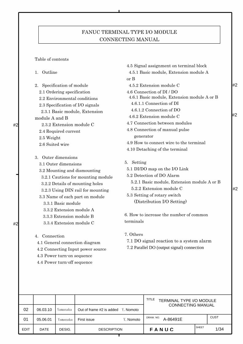
Table of contents 1. Outline 2. Specification of module
2.1 Ordering specification 2.2 Environmental conditions 2.3 Specification of I/O signals 2.3.1 Basic module, Extension
module A and B 2.3.2 Extension module C 2.4 Required current 2.5 Weight 2.6 Suited wire
3. Outer dimensions
3.1 Outer dimensions 3.2 Mounting and dismounting 3.2.1 Cautions for mounting module 3.2.2 Details of mounting holes 3.2.3 Using DIN rail for mounting 3.3 Name of each part on module
3.3.1 Basic module 3.3.2 Extension module A 3.3.3 Extension module B
3.3.4 Extension module C 4. Connection 4.1 General connection diagram 4.2 Connecting Input power source 4.3 Power turn-on sequence 4.4 Power turn-off sequence
4.5 Signal assignment on terminal block 4.5.1 Basic module, Extension module A or B 4.5.2 Extension module C 4.6 Connection of DI / DO 4.6.1 Basic module, Extension module A or B
4.6.1.1 Connection of DI 4.6.1.2 Connection of DO
4.6.2 Extension module C 4.7 Connection between modules 4.8 Connection of manual pulse
generator 4.9 How to connect wire to the terminal 4.10 Detaching of the terminal
5. Setting 5.1 DI/DO map on the I/O Link 5.2 Detection of DO Alarm
5.2.1 Basic module, Extension module A or B 5.2.2 Extension module C
5.3 Setting of rotary switch (Distribution I/O Setting)
6. How to increase the number of common terminals 7. Others 7.1 DO signal reaction to a system alarm 7.2 Parallel DO (output signal) connection
#2
#2
#2
#2
#2
1/34
TERMINAL TYPE I/O MODULECONNECTING MANUAL
EDIT F A N U C SHEET
DRAW. NO. CUST
TITLE
02
06.03.10
Yamanaka
DESCRIPTION DESIG. DATE
01 05.06.01 Yamanaka First issue Y.Nomoto
Out of frame #2 is added Y.Nomoto
A-86491E
FANUC TERMINAL TYPE I/O MODULE CONNECTING MANUAL

1. Outline Specification of terminal type I/O module is based on connector panel I/O module. The strong points of terminal type I/O module are below.
- Using ferrule terminal for connect input/output signal. - LED which indicates On/Off state every input/output signal. - 16 points of digital output and 24 points of digital input for one module.
(Extension module C has no DI.) - Photo coupler insulation is adopted for output circuit. - It is possible to install in the DIN rail. - Using extension modules, the maximum point input: 96 points and
outputs: 64 points. - The terminal block can be detached from module. - There is Extension module with MPG (The manual pulse generator) interface.
#2
2/
TERMINAL TYPE I/O MODULECONNECTING MANUAL
EDIT F A N U C SHEET
DRAW. NO. CUST
TITLE
DESCRIPTION DESIG. DATE
02 06.03.10 Yamanaka Out of frame #2 is added
A-86491E
CNC
Terminal type I/O
(Basic module)
Connection I/O
I/O Link
I/O Link
Input Output 24pt 16pt
Terminal type I/O
(Extension module)
It is possible to connect up to 3 extension modules with the flat cable.
Input Output 24pt 16pt
Extension cable Extension cable

2.Specification of module 2.1 Ordering specification
Name Ordering specification Specification of module Basic module A03B-0823-C001 DI 24pt / DO 16pt
With I/O Link I/F Extension module A A03B-0823-C002 DI 24pt / DO 16pt
With MPG I/F Note) Connect extension module A next to basic module.
Extension module B A03B-0823-C003 DI 24pt / DO 16pt Without MPG I/F
Extension module C A03B-0823-C004 DO 16pt, Max 2A/pt 2A output module
Spare fuse A03B-0823-K001 2A (for Basic module) Spare terminals set (For Basic module or
Extension module A or B)
A03B-0823-K010 Terminal block for cable side (T1-T4) Note) Terminal block for cable side is attached with module. This set is for maintenance.
Spare terminals set (For extension module C)
A03B-0823-K011 Terminal block for cable side (T1,T2) Note) Terminal block for cable side is attached with module. This set is for maintenance.
Extension cable A A03B-0823-K100 Length of cable is 100mm. It is necessary to use this cable for using extension module.
2.2 Environmental conditions The terminal type I/O module have been designed on the assumption that they are housed in closed cabinets. The environmental conditions when installing these cabinets shall conform to the following table. Item Specification Power supply for the control and input circuits
24VDC±10%
Ambient temperature In operation:0~55ºC In storage or transportation:-20~60ºC
Variations in temperature Up to 1.1ºC per minute Humidity General condition : 75% or lower (relative humidity)
Short–period condition (up to one month) : Up to 95% Vibration 0.5G or less (Operating), 1.0G or less (Non-operating)
FANUC conducted an evaluation test under the following conditions: 10 to 58 Hz: 0.075 mm (amplitude) 58 to 500Hz: 1G Direction of vibration: Each of the X, Y, and Z directions Number of sweep cycles: 10
Conforming to IEC68-2-6 Environment
Normal machine shop environment (The environment must be considered if the cabinets are in a location where the density of dust, coolant, organic solvent, and/or corrosive gas is relatively high.)
#2
#2
3/
TERMINAL TYPE I/O MODULECONNECTING MANUAL
EDIT F A N U C SHEET
DRAW. NO. CUST
TITLE
DESCRIPTION DESIG. DATE
02 06.03.10 Yamanaka Out of frame #2 is added
A-86491E
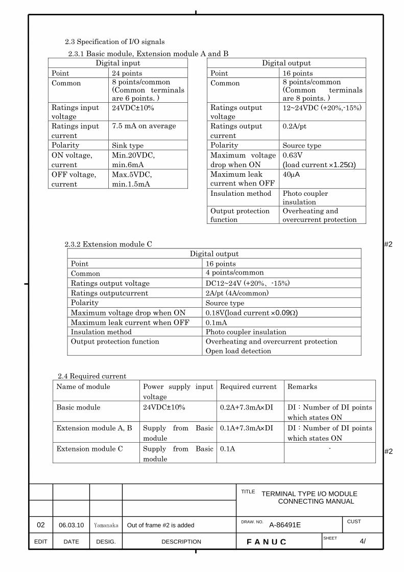
2.3 Specification of I/O signals 2.3.1 Basic module, Extension module A and B
Digital input Digital output Point 24 points Point 16 points Common 8 points/common
(Common terminals are 6 points. )
Common 8 points/common (Common terminals are 8 points. )
Ratings input voltage
24VDC±10% Ratings output voltage
12~24VDC (+20%,-15%)
Ratings input current
7.5 mA on average
Ratings output current
0.2A/pt
Polarity Sink type Polarity Source type ON voltage, current
Min.20VDC, min.6mA
Maximum voltage drop when ON
0.63V (load current ×1.25Ω)
OFF voltage, current
Max.5VDC, min.1.5mA
Maximum leak current when OFF
40μA
Insulation method Photo coupler insulation
Output protection function
Overheating and overcurrent protection
2.3.2 Extension module C
Digital output Point 16 points Common 4 points/common Ratings output voltage DC12~24V (+20%、-15%) Ratings outputcurrent 2A/pt (4A/common) Polarity Source type Maximum voltage drop when ON 0.18V(load current ×0.09Ω) Maximum leak current when OFF 0.1mA Insulation method Photo coupler insulation Output protection function Overheating and overcurrent protection
Open load detection
2.4 Required current Name of module Power supply input
voltage Required current Remarks
Basic module 24VDC±10% 0.2A+7.3mA×DI DI : Number of DI points which states ON
Extension module A, B Supply from Basic module
0.1A+7.3mA×DI DI : Number of DI points which states ON
Extension module C Supply from Basic module
0.1A -
#2
#2
4/
TERMINAL TYPE I/O MODULECONNECTING MANUAL
EDIT F A N U C SHEET
DRAW. NO. CUST
TITLE
DESCRIPTION DESIG. DATE
02 06.03.10 Yamanaka Out of frame #2 is added
A-86491E
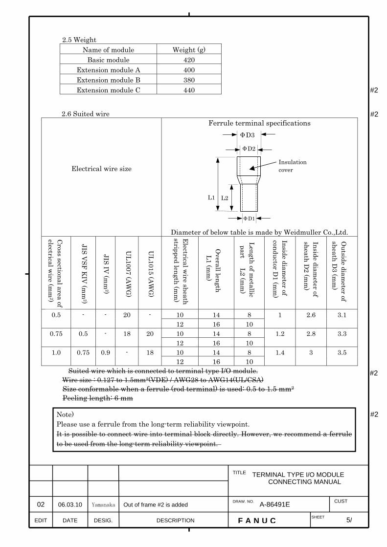
2.5 Weight Name of module Weight (g)
Basic module 420 Extension module A 400 Extension module B 380 Extension module C 440
2.6 Suited wire
Electrical wire size
Ferrule terminal specifications
Diameter of below table is made by Weidmuller Co.,Ltd.
10 14 8 0.5 - - 20 - 12 16 10
1 2.6 3.1
10 14 8 0.75 0.5 - 18 20 12 16 10
1.2 2.8 3.3
10 14 8 1.0 0.75 0.9 - 18 12 16 10
1.4 3 3.5
Suited wire which is connected to terminal type I/O module. Wire size : 0.127 to 1.5mm2(VDE) / AWG28 to AWG14(UL/CSA) Size conformable when a ferrule (rod terminal) is used: 0.5 to 1.5 mm2 Peeling length: 6 mm
#2
#2
#2
#2
Note) Please use a ferrule from the long-term reliability viewpoint. It is possible to connect wire into terminal block directly. However, we recommend a ferruleto be used from the long-term reliability viewpoint.
5/
TERMINAL TYPE I/O MODULECONNECTING MANUAL
EDIT F A N U C SHEET
DRAW. NO. CUST
TITLE
DESCRIPTION DESIG. DATE
02 06.03.10 Yamanaka Out of frame #2 is added
A-86491E
ΦD1
L2 L1
Insulation cover
ΦD2
ΦD3
Inside diameter of
conductor D1 (m
m)
Inside diameter of
sheath D2 (m
m)
Outside diam
eter of sheath D
3 (mm
)
Length of metallic
part L2 (mm
)
Overall length L1 (m
m)
Electrical w
ire sheath stripped length (m
m)
UL1015 (A
WG
)
UL1007 (A
WG
)
JIS IV (m
m2)
JIS VSF K
IV (m
m2)
Cross sectional area of
electrical wire (m
m2)

6/
TERMINAL TYPE I/O MODULECONNECTING MANUAL
EDIT F A N U C SHEET
DRAW. NO. CUST
TITLE
DESCRIPTION DESIG. DATE
A-86491E
3.Outer dimensions 3.1 Outer dimensions (Each module commonness)
Unit:mm
At maximum composition ( 1 Basic module and 3 Extension modules )
280
150
7/
TERMINAL TYPE I/O MODULECONNECTING MANUAL
EDIT F A N U C SHEET
DRAW. NO. CUST
TITLE
DESCRIPTION DESIG. DATE
A-86491E
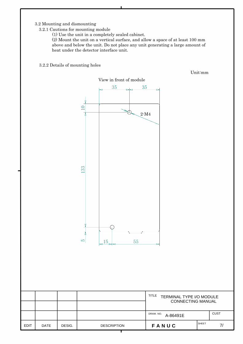
3.2 Mounting and dismounting 3.2.1 Cautions for mounting module
(1) Use the unit in a completely sealed cabinet. (2) Mount the unit on a vertical surface, and allow a space of at least 100 mm
above and below the unit. Do not place any unit generating a large amount of heat under the detector interface unit.
3.2.2 Details of mounting holes Unit:mm
View in front of module
2-M4
8/
TERMINAL TYPE I/O MODULECONNECTING MANUAL
EDIT F A N U C SHEET
DRAW. NO. CUST
TITLE
DESCRIPTION DESIG. DATE
A-86491E
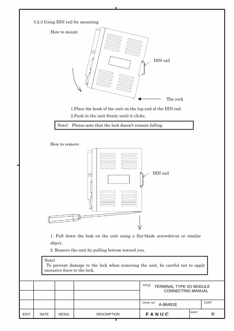
3.2.3 Using DIN rail for mounting
How to mount
1.Place the hook of the unit on the top end of the DIN rail 2.Push in the unit firmly until it clicks.
How to remove
1. Pull down the look on the unit using a flat-blade screwdriver or similar object. 2. Remove the unit by pulling bottom toward you.
DIN rail
Note) To prevent damage to the lock when removing the unit, be careful not to applyexcessive force to the lock.
DIN rail
The rock
Note) Please note that the lock doesn't remain falling.

9/
TERMINAL TYPE I/O MODULE
CONNECTING MANUAL
EDIT F A N U C SHEET
DRAW. NO. CUST
TITLE
DESCRIPTION DESIG. DATE
A-86491E
3.3 Name of each part on module 3.3.1 Basic module
A03B-0823-C001
CA105 Connector for Extension cable
Figure seen from direction of A of above figure
LED which indicates state of DI/DO
T1 : Terminal for DO T2 : Terminal for DO
T4 : Terminal for DI
CP11A Connector for inputpower supply
CP11B Connector of output 24VDC for use branchimg
LED for state of powersupply
JD1B (I/O LINK)
JD1A (I/O LINK)
A (Refer to thefigure below.)
FUSE 2A
T3 : Terminal for DI

10/
TERMINAL TYPE I/O MODULE
CONNECTING MANUAL
EDIT F A N U C SHEET
DRAW. NO. CUST
TITLE
DESCRIPTION DESIG. DATE
A-86491E
3.3.2 Extension module A
A03B-0823-C002
LED which indicates state of DI/DO
T1 : Terminal for DO T2 : Terminal for DO
T4 : Terminal for DI
Rotary switch
JA3 (MPG)
A (Refer to thefigure below.)
T3 : Terminal for DI
CA105 Connector for Extension cable ( To the next extension module)
Figure seen from direction of A of above figure
CA106 Connector for Extension cable ( To the preceding basic module)
Note) Connect extension module A next to basic module.
11/
TERMINAL TYPE I/O MODULE
CONNECTING MANUAL
EDIT F A N U C SHEET
DRAW. NO. CUST
TITLE
DESCRIPTION DESIG. DATE
A-86491E
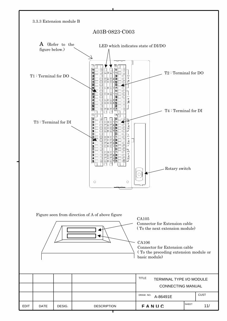
3.3.3 Extension module B
A03B-0823-C003
LED which indicates state of DI/DO
T1 : Terminal for DO T2 : Terminal for DO
T4 : Terminal for DI
Rotary switch
A (Refer to thefigure below.)
T3 : Terminal for DI
CA105 Connector for Extension cable ( To the next extension module)
Figure seen from direction of A of above figure
CA106 Connector for Extension cable ( To the preceding extension module or basic module)

12/
TERMINAL TYPE I/O MODULE
CONNECTING MANUAL
EDIT F A N U C SHEET
DRAW. NO. CUST
TITLE
DESCRIPTION DESIG. DATE
02 06.03.10 Yamanaka This page is added
A-86491E
3.3.4 Extension module C
A03B-0823-C004
CA105 Connector for Extension cable (To the next extension module)
Figure seen from direction of A of above figure
CA106 Connector for Extension cable (To the preceding extension module or basic module)
LED (green) which indicates state of DO
T1 : Terminal for DO Label color : light blue
T2 : Terminal for DO Label color : yellowish green
Rotary switch
A (Refer to thefigure below.)
LED (red) which indicates state of DO alarm
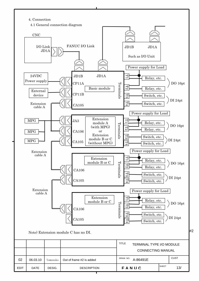
4. Connection 4.1 General connection diagram
Note) Extension module C has no DI.
#2
13/
TERMINAL TYPE I/O MODULE
CONNECTING MANUAL
EDIT F A N U C SHEET
DRAW. NO. CUST
TITLE
DESCRIPTION DESIG. DATE
02 06.03.10 Yamanaka Out of frame #2 is added
A-86491E
CNC
JD1B JD1A
I/O Link JD1A
JD1B JD1A
CP11A
24VDC Power supply
Such as I/O Unit
Basic module
FANUC I/O Link
CP11B
CA105
External device
T1 T2
T3 T4
Terminals
Power supply for Load
Relay, etc.
Switch, etc.
CA105
CA106
JA3 MPG
MPG
MPG
Extensioncable A
DO 16pt
DI 24pt
T1 T2
T3 T4 T1
T2 T3 T4
T1 T2
T3 T4
CA105
CA106
CA105
CA106
DO 16pt
DI 24pt
Relay, etc.
Switch, etc.
Extension module A
(with MPG) or
Extension module B or C (without MPG)
Terminals
Extension module B or C Term
inals
Extension module B or C Term
inals
Power supply for Load
Relay, etc.
Relay, etc.
Switch, etc.
Switch, etc.
DO 16pt
DI 24pt
Power supply for Load
Relay, etc.
Relay, etc.
Switch, etc.
Switch, etc.
DO 16pt
DI 24pt
Power supply for Load
Relay, etc.
Relay, etc.
Switch, etc.
Switch, etc.
Extension cable A
Extension cable A

4.2 Connecting Input power source Supply power to this unit from CNC or external resource.
The 24V DC input to CP11A(A1,A2) can be output from CP11B(B1,B2) for use branchimg. The connection of CP11B(B1,B2) is as shown below. In this case, the external 24V DC power supply should have a rating which is equal to the sum of the current consumed by the control unit and the current used via CP11B(B1,B2). Maximum current which is supplied from CP11B is 2A.
#2
24VDC stabilized power
(24VDC±10%)
CP11B Select a source that meets
the external power terminal
Tyco Electronics AMP 1-178288-3 (housing) 1-175218-5 (contact)
Basic module External power
Recommended cable (using external power) : A02B-0124-K830(5m)
(Crimp terminal of size M3 is available on the external power side)
Key arrangement
Connect for input
Input A3 A2 A1
0V +24V
B3 B2 B1
0V +24E Output
CP11A
External device
Select a connector that
matches the pin layout
of the external device.
Tyco Electronics AMP2-178288-3 (housing) 1-175218-5 (contact)
Connect for external device
Basic module
CP11B
Key arrangement
Input A3 A2 A1
0V +24V
B3 B2 B1
0V +24E Output
CP11A
14/
TERMINAL TYPE I/O MODULE
CONNECTING MANUAL
EDIT F A N U C SHEET
DRAW. NO. CUST
TITLE
DESCRIPTION DESIG. DATE
02 06.03.10 Yamanaka Out of frame #2 is added
A-86491E
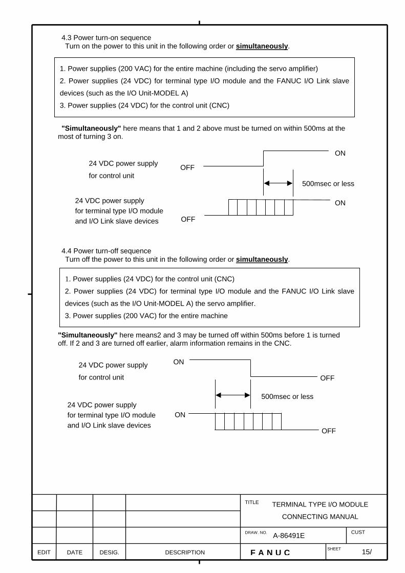
4.3 Power turn-on sequence Turn on the power to this unit in the following order or simultaneously. "Simultaneously" here means that 1 and 2 above must be turned on within 500ms at the most of turning 3 on. 4.4 Power turn-off sequence Turn off the power to this unit in the following order or simultaneously. "Simultaneously" here means2 and 3 may be turned off within 500ms before 1 is turned off. If 2 and 3 are turned off earlier, alarm information remains in the CNC.
1. Power supplies (200 VAC) for the entire machine (including the servo amplifier)
2. Power supplies (24 VDC) for terminal type I/O module and the FANUC I/O Link slave
devices (such as the I/O Unit-MODEL A)
3. Power supplies (24 VDC) for the control unit (CNC)
OFF
ON
OFF
ON
500msec or less
24 VDC power supply
for control unit
24 VDC power supply for terminal type I/O module and I/O Link slave devices
1. Power supplies (24 VDC) for the control unit (CNC)
2. Power supplies (24 VDC) for terminal type I/O module and the FANUC I/O Link slave
devices (such as the I/O Unit-MODEL A) the servo amplifier.
3. Power supplies (200 VAC) for the entire machine
OFF
ON
OFF
ON
500msec or less
24 VDC power supply
for control unit
24 VDC power supply for terminal type I/O module and I/O Link slave devices
15/
TERMINAL TYPE I/O MODULE
CONNECTING MANUAL
EDIT F A N U C SHEET
DRAW. NO. CUST
TITLE
DESCRIPTION DESIG. DATE
A-86491E

4.5 Signal assignment on terminal block (Each module commonness) 4.5.1 Basic module, Extension module A or B
Signal assignment for output T1 (Label color : light blue) T2 (Label color : yellowish green) 1 DOCOM0 V 1 DOCOM0 V 2 Yn+0.0 0 2 Yn+0.1 1 3 0V-0 G 3 0V-0 G 4 Yn+0.2 2 4 Yn+0.3 3 5 Yn+0.4 4 5 Yn+0.5 5 6 0V-0 G 6 0V-0 G 7 Yn+0.6 6 7 Yn+0.7 7 8 DOCOM1 V 8 DOCOM1 V 9 Yn+1.0 0 9 Yn+1.1 1
10 0V-1 G 10 0V-1 G 11 Yn+1.2 2 11 Yn+1.3 3 12 Yn+1.4 4 12 Yn+1.5 5 13 0V-1 G 13 0V-1 G 14 Yn+1.6 6 14 Yn+1.7 7
Indication on label
Signal assignment for Input T3 (Label color : yellow) T4 (Label color : pink)
1 DICOM C 1 DICOM C 2 Xm+0.0 0 2 Xm+0.1 1 3 Xm+0.2 2 3 Xm+0.3 3 4 Xm+0.4 4 4 Xm+0.5 5 5 Xm+0.6 6 5 Xm+0.7 7 6 DICOM C 6 DICOM C 7 Xm+1.0 0 7 Xm+1.1 1 8 Xm+1.2 2 8 Xm+1.3 3 9 Xm+1.4 4 9 Xm+1.5 5
10 Xm+1.6 6 10 Xm+1.7 7 11 DICOM C 11 DICOM C 12 Xm+2.0 0 12 Xm+2.1 1 13 Xm+2.2 2 13 Xm+2.3 3 14 Xm+2.4 4 14 Xm+2.5 5 15 Xm+2.6 6 15 Xm+2.7 7
Indication on label Specification of terminal block
Name of terminal
Specification of cable side Remarks
T1 T2
Weidmuller BLZF3.5/14F Terminal blocks (T1 and T2) have colored label each other. Each terminal blocks (T1 and T2) have protection parts (type:BL/SL3.50KO) against incorrect insertion.
T3 T4
Weidmuller BLZF3.5/15F Terminal blocks (T3 and T4) have colored label each other. Each terminal blocks (T3 and T4) have protection parts (type:BL/SL3.50KO) against incorrect insertion.
Note) Terminal blocks for cable side are attached with terminal type I/O module.
#2
#2
#2
#2
16/
TERMINAL TYPE I/O MODULE
CONNECTING MANUAL
EDIT F A N U C SHEET
DRAW. NO. CUST
TITLE
DESCRIPTION DESIG. DATE
02 06.03.10 Yamanaka Out of frame #2 is changed
A-86491E

17/
TERMINAL TYPE I/O MODULE
CONNECTING MANUAL
EDIT F A N U C SHEET
DRAW. NO. CUST
TITLE
DESCRIPTION DESIG. DATE
02 06.03.10 Yamanaka This page is added
A-86491E
4.5.2 Extension module C
Signal assignment for output T1 (Label color : light blue)
1 DOCOM0 V 2 Yn+0.0 0 3 0V-0 G 4 Yn+0.1 1 5 Yn+0.2 2 6 0V-0 G 7 Yn+0.3 3 8 DOCOM1 V 9 Yn+0.4 4 10 0V-1 G 11 Yn+0.5 5 12 Yn+0.6 6 13 0V-1 G 14 Yn+0.7 7
T2 (Label color : yellowish green) 1 DOCOM2 V 2 Yn+1.0 0 3 0V-2 G 4 Yn+1.1 1 5 Yn+1.2 2 6 0V-2 G 7 Yn+1.3 3 8 9 DOCOM3 V 10 Yn+1.4 4 11 0V-3 G 12 Yn+1.5 5 13 Yn+1.6 6 14 0V-3 G 15 Yn+1.7 7
Specification of terminal block
Name of terminal Specification of cable side T1 Weidmuller BLZF3.5/14F T2 Weidmuller BLZF3.5/15F
Note) Terminal blocks for cable side are attached with terminal type I/O module.
Indication on label
Indication on label

4.6 Connection of DI / DO (Each module commonness) 4.6.1 Basic module, Extension module A or B 4.6.1.1 Connection of DI
#2
The circuit in the dotted line the above-mentioned is mounted only on a basic module. 24V ofDICOM is supplied from a basic module or preceding extension module by way of extension cable.
A1
A2
CP11
B1
B2
24VIN
0VIN
24VOUT
0VOUT CP11
I Xm+0.0 Xm+0.1 Xm+0.2 Xm+0.3 Xm+0.4 Xm+0.5 Xm+0.6 Xm+0.7
T3-2 T4-2 T3-3 T4-3 T3-4 T4-4 T3-5 T4-5
I I
I I I I
I T3-7 T4-7 T3-8 T4-8 T3-9 T4-9 T3-10 T4-10
I
I I
I I I I
I T3-12 T4-12 T3-13 T4-13 T3-14 T4-14 T3-15 T4-15
I
I I
I I I I
24V
0V
Internal Terminal name and pin number of terminal block
T3-1 T3-6 T3-11 T4-1 T4-6 T4-11
Switch, etc.
Signal name
24VDC Power Supply
DICOM DICOM DICOM DICOM DICOM DICOM
(Connect to extension module)
Extension connector
Xm+1.0 Xm+1.1 Xm+1.2 Xm+1.3 Xm+1.4 Xm+1.5 Xm+1.6 Xm+1.7
Xm+2.0 Xm+2.1 Xm+2.2 Xm+2.3 Xm+2.4 Xm+2.5 Xm+2.6 Xm+2.7
2A
24V
0V
Fuse
External device
Control
I
Receiver
0V
Input terminal
LED
Input circuit
Control : Control circuit
I
C C C C C C
0 1 2 3 4 5 6 7
0 1 2 3 4 5 6 7
0 1 2 3 4 5 6 7
Indication on label
18/
TERMINAL TYPE I/O MODULE
CONNECTING MANUAL
EDIT F A N U C SHEET
DRAW. NO. CUST
TITLE
DESCRIPTION DESIG. DATE
02 06.03.10 Yamanaka Out of frame #2 is added
A-86491E
Bit number
Address number

4.6.1.2 Connection of DO
#2
Internal
circuit
O Output circuit
Output terminal
DOCOM0 or
DOCOM1
0V-0 or
0V-1
LED
O
Terminal name and pin number of terminal block
L
O L
O L
O L
O L
O L
O L
O L
Yn+0.0 Yn+0.1 Yn+0.2 Yn+0.3 Yn+0.4 Yn+0.5 Yn+0.6 Yn+0.7
T1-1 T2-1 T1-2 T2-2 T1-4 T2-4 T1-5 T2-5 T1-7 T2-7 T1-3 T2-3 T1-6 T2-6
Power supply for LOAD
O L
O L
O L
O L
O L
O L
O L
O L
Yn+1.0 Yn+1.1 Yn+1.2 Yn+1.3 Yn+1.4 Yn+1.5 Yn+1.6 Yn+1.7
T1-8 T2-8 T1-9 T2-9 T1-11 T2-11 T1-12 T2-12 T1-14 T2-14 T1-10 T2-10 T1-13 T2-13
Power supply for LOAD
Signal name
+
-
+
-
:Load L
DOCOM0 DOCOM0
DOCOM1 DOCOM1
0V-0 0V-0 0V-0 0V-0
0V-1 0V-1 0V-1 0V-1
Internal
0 1 2 3 4 5 6 7
G G G G
V V
0 1 2 3 4 5 6 7 G G G G
V V
Indication on label
19/
TERMINAL TYPE I/O MODULE
CONNECTING MANUAL
EDIT F A N U C SHEET
DRAW. NO. CUST
TITLE
DESCRIPTION DESIG. DATE
02 06.03.10 Yamanaka Out of frame #2 is added
A-86491E
Address number
Bit number
20/
TERMINAL TYPE I/O MODULE
CONNECTING MANUAL
EDIT F A N U C SHEET
DRAW. NO. CUST
TITLE
DESCRIPTION DESIG. DATE
02 06.03.10 Yamanaka This page is added
A-86491E
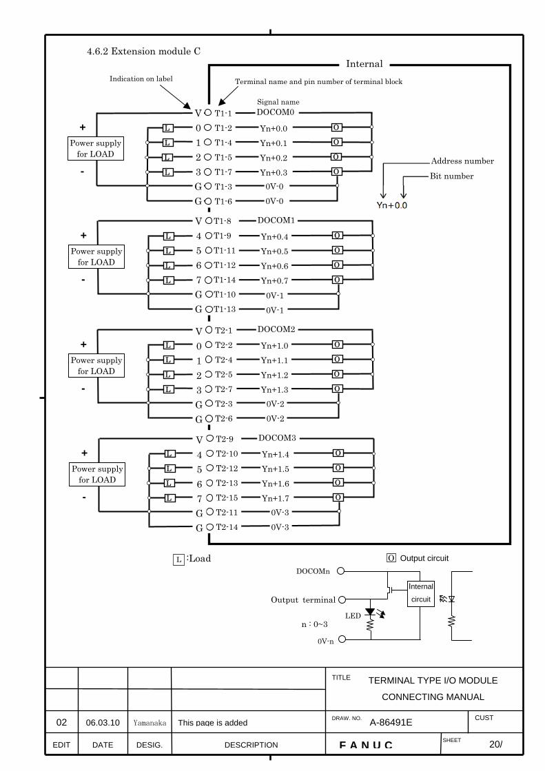
4.6.2 Extension module C
O
Terminal name and pin number of terminal block
L
O L
O L
O L
Yn+0.0 Yn+0.1 Yn+0.2 Yn+0.3
T1-1 T1-2 T1-4 T1-5 T1-7 T1-3 T1-6
Power supply for LOAD
Signal name
+
-
:Load L
DOCOM0
0V-0 0V-0
Internal
O L
O L
O L
O L
Yn+0.4 Yn+0.5 Yn+0.6 Yn+0.7
T1-8 T1-9 T1-11 T1-12 T1-14 T1-10 T1-13
Power supply for LOAD
+
-
DOCOM1
0V-1 0V-1
O L
O L
O L
O L
Yn+1.0 Yn+1.1 Yn+1.2 Yn+1.3
T2-1 T2-2 T2-4 T2-5 T2-7 T2-3 T2-6
Power supply for LOAD
+
-
DOCOM2
0V-2 0V-2
O L
O L
O L
O L
Yn+1.4 Yn+1.5 Yn+1.6 Yn+1.7
T2-9 T2-10 T2-12 T2-13 T2-15 T2-11 T2-14
Power supply for LOAD
+
-
DOCOM3
0V-3 0V-3
Internal
circuit
O Output circuit
Output terminal
DOCOMn
0V-n
LED n : 0~3
V 0 1 2 3 G G
V 4 5 6 7 G G
V 0 1 2 3 G G
V 4 5 6 7 G G
Indication on label
Address number
Bit number

21/
TERMINAL TYPE I/O MODULE
CONNECTING MANUAL
EDIT F A N U C SHEET
DRAW. NO. CUST
TITLE
DESCRIPTION DESIG. DATE
A-86491E
4.7 Connection between modules
A way to connect between each modules are same way. The flat cable is connected with the connector (CA105, CA106) that mounted in each modules as shown in the figure below. In that case, please connect all of the 52 pins carefully in the direction of the connector.
Cross section Method of removing connected cable Please release the lock pushing the latch of the connector on the cable side in the direction of the arrow as shown in below when you remove connected cable from the module.
CA105 CA105
CA106
CA105
CA106 CA106
Extension cable A
Basic module Extension moduleA, B or C
Extension module B or C
Extension module B or C
Extension cable A Extension cable A

22/
TERMINAL TYPE I/O MODULE
CONNECTING MANUAL
EDIT F A N U C SHEET
DRAW. NO. CUST
TITLE
DESCRIPTION DESIG. DATE
A-86491E
4.8 Connection of manual pulse generator An example in which three manual pulse generators are connected to Extension module A is shown below. The manual pulse generator can be connected only for the i series CNC.
Recommended wire material:A66L–0001–0286 (#20 AWG × 6 + #24 AWG × 3 pairs) Recommended connector:A02B–0120–K303 (including the following connector and case)
(Connector: FI40–2015S (Hirose Electric Co., Ltd.)) (Case: FI40–20–CV5 (Hirose Electric Co., Ltd.))
Recommended cables:A02B–0120–K841 (7 m) (for connecting three manual pulse generators) A02B–0120–K848 (7 m) (for connecting two manual pulse generators) A02B–0120–K847 (7 m) (for connecting one manual pulse generator)
(These cables do not include the wire shown in the above figure.)
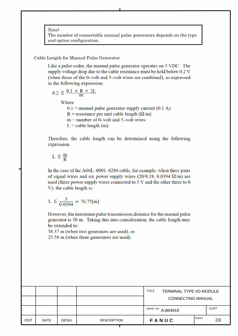
Cable Length for Manual Pulse Generator
Note) The number of connectable manual pulse generators depends on the type and option configuration.
EDIT F A N U C SHEET
DRAW. NO. CUST
TITLE
23/ DESCRIPTION DESIG. DATE
TERMINAL TYPE I/O MODULE
CONNECTING MANUAL
A-86491E

4.9 How to connect wire to the terminal (1) Insert a screwdriver whose up-to-date width is about 2.5mm into the clamp of the terminal block, and open the fixing bracket. (2) Insert the cable with ferrule into the terminal block. (3) Pull the driver from the clamp and the wiring completion.
The clamp
Flat–bladed screwdriver
Note) Do not pry the driver inside of the clamp. The terminal block might be damaged.
Use recommendation flat–bladed screwdriver
Weidmuller : Product number SDI 0.4X2.5X80
EDIT F A N U C SHEET
DRAW. NO. CUST
TITLE
24/ DESCRIPTION DESIG. DATE
TERMINAL TYPE I/O MODULE
CONNECTING MANUAL
A-86491E

4.10 Detaching of the terminal The terminal block can be detached from the module by loosening the installation screw at both ends of the terminal block. The torque of the installation screw : 0.4Nm (max).
The installation screw
Terminal block
EDIT F A N U C SHEET
DRAW. NO. CUST
TITLE
25/ DESCRIPTION DESIG. DATE
TERMINAL TYPE I/O MODULE
CONNECTING MANUAL
A-86491E
The installation screw

5 Setting 5.1 DI/DO map on the I/O Link
Basically, terminal type I/O module is allocated a group of DI addresses (16 bytes) and a group of DO addresses (8 bytes). Up to three hardware Extension modules can be added or removed as required. The reason for this address allocation is explained below. The MPG interface (MPG counter) occupies a DI space from Xm+12 through Xm+14. These addresses are fixed regardless of whether Extension module 2 or 3 is used, and Xm+12 through Xm+14 must be allocated as a DI work area to enable the use of the MPG. Therefore, when using an MPG for the i series CNC, allocate DI addresses in units of 16 bytes. Do not use the DI space from Xm+12 through Xm+14 for Ladder; the CNC processes the MPG counter value directly. DI address Xm+15 is used for detecting overcurrent and overheating alarms that occur in the IC used in the DO driver. [For details, see the section describing the detection of DO (output signal) alarms.] This address is fixed regardless of whether Extension module 2 or 3 is used, and it must be allocated as a work area before it can be used. When using this area, therefore, allocate DI addresses in units of 16 bytes. ・As for address of Extension module C Extension module C is output module. In this module, DO alarm detection is assigned in DI area and occupy 2 bytes every module. Refer to section 5.2.2 about relation between address of DO and DO alarm detection.
#2
#2
26/
TERMINAL TYPE I/O MODULE
CONNECTING MANUAL
EDIT F A N U C SHEET
DRAW. NO. CUST
TITLE
DESCRIPTION DESIG. DATE
02 06.03.10 Yamanaka Out of frame #2 is added A-86491E
This area is not used in Extension module C.
Extension
Extension
Extension
Extension
Extension
Extension
Extension
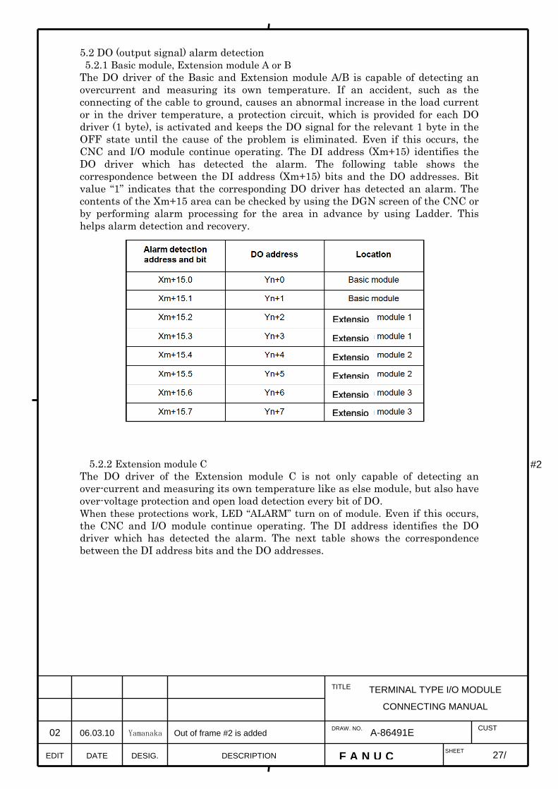
5.2 DO (output signal) alarm detection 5.2.1 Basic module, Extension module A or B The DO driver of the Basic and Extension module A/B is capable of detecting an overcurrent and measuring its own temperature. If an accident, such as the connecting of the cable to ground, causes an abnormal increase in the load current or in the driver temperature, a protection circuit, which is provided for each DO driver (1 byte), is activated and keeps the DO signal for the relevant 1 byte in the OFF state until the cause of the problem is eliminated. Even if this occurs, the CNC and I/O module continue operating. The DI address (Xm+15) identifies the DO driver which has detected the alarm. The following table shows the correspondence between the DI address (Xm+15) bits and the DO addresses. Bit value “1” indicates that the corresponding DO driver has detected an alarm. The contents of the Xm+15 area can be checked by using the DGN screen of the CNC or by performing alarm processing for the area in advance by using Ladder. This helps alarm detection and recovery.
5.2.2 Extension module C The DO driver of the Extension module C is not only capable of detecting an over-current and measuring its own temperature like as else module, but also have over-voltage protection and open load detection every bit of DO. When these protections work, LED “ALARM” turn on of module. Even if this occurs, the CNC and I/O module continue operating. The DI address identifies the DO driver which has detected the alarm. The next table shows the correspondence between the DI address bits and the DO addresses.
#2
27/
TERMINAL TYPE I/O MODULE
CONNECTING MANUAL
EDIT F A N U C SHEET
DRAW. NO. CUST
TITLE
DESCRIPTION DESIG. DATE
02 06.03.10 Yamanaka Out of frame #2 is added
A-86491E
Extensio
Extensio
Extensio
Extensio
Extensio
Extensio

28/
TERMINAL TYPE I/O MODULE
CONNECTING MANUAL
EDIT F A N U C SHEET
DRAW. NO. CUST
TITLE
DESCRIPTION DESIG. DATE
02 06.03.10 Yamanaka This page is added
A-86491E
・Address of DO alarm when three Extension module C are assigned in Extension module 1,2 and 3. (“0” means nothing DO alarm. “1” means that DO alarm happen.) *=Don’t care
bit Address 7 6 5 4 3 2 1 0
Module
Xm+3 Yn+2 Bit7
Yn+2 Bit6
Yn+2 Bit5
Yn+2 Bit4
Yn+2 Bit3
Yn+2 Bit2
Yn+2 Bit1
Yn+2 Bit0
Xm+4 Yn+3 Bit7
Yn+3 Bit6
Yn+3 Bit5
Yn+3 Bit4
Yn+3 Bit3
Yn+3 Bit2
Yn+3 Bit1
Yn+3 Bit0
Xm+5 * * * * * * * *
DO alarm of Extension module 1
Xm+6 Yn+4 Bit7
Yn+4 Bit6
Yn+4 Bit5
Yn+4 Bit4
Yn+4 Bit3
Yn+4 Bit2
Yn+4 Bit1
Yn+4 Bit0
Xm+7 Yn+5 Bit7
Yn+5 Bit6
Yn+5 Bit5
Yn+5 Bit4
Yn+5 Bit3
Yn+5 Bit2
Yn+5 Bit1
Yn+5 Bit0
Xm+8 * * * * * * * *
DO alarm of Extension module 2
Xm+9 Yn+6 Bit7
Yn+6 Bit6
Yn+6 Bit5
Yn+6 Bit4
Yn+6 Bit3
Yn+6 Bit2
Yn+6 Bit1
Yn+6 Bit0
Xm+10 Yn+7 Bit7
Yn+7 Bit6
Yn+7 Bit5
Yn+7 Bit4
Yn+7 Bit3
Yn+7 Bit2
Yn+7 Bit1
Yn+7 Bit0
Xm+11 * * * * * * * *
DO alarm of Extension module 3
・Viewpoint of above table. DO alarm which data is assigned in address bit5 of Yn+3 is set in address bit5 of Xm+4. Bit value “1” indicates that the corresponding DO driver has detected an alarm. The contents of DI area can be checked by using the DGN screen of the CNC or by performing alarm processing for the area in advance by using Ladder. This helps alarm detection and recovery. When alarm detection works, shutdown DO and power supply of system, and reduce the source of alarm.
Note) DO alarm information is set above address area, not Xm+15. The address Xm+5, Xm+8 and Xm+11 are not used in extension module C. If extension module A or B is assigned in extension 1 or 2, area of address does not shift.

29/
TERMINAL TYPE I/O MODULE
CONNECTING MANUAL
EDIT F A N U C SHEET
DRAW. NO. CUST
TITLE
DESCRIPTION DESIG. DATE
02 06.03.10 Yamanaka This page is added
A-86491E
When protections work, state of DO and DO alarm are below.
State Output of
PMC
State of DO
driver
DO LED
(Green)
Alarm LED
(Red)
Alarm information
assigned in DI
Normal 0 OFF Turn off Turn off 0
1 ON Turn on Turn off 0
Over-current 0 OFF Turn off Turn off 0
Protection 1 OFF Turn off Turn on 1
Over-voltage 0 OFF Turn off Turn on 1
protection 1 OFF Turn off Turn off 0
Open load 0 OFF Turn off Turn off 0
detection 1 ON Turn on Turn on 1 Note) When over-current protection or over-voltage protection is activated, a protection circuit, which is provided for each DO driver (1 bit) keeps the DO signal for the relevant 1 bit in the OFF state until the cause of the problem is eliminated. After problem is removed, DO driver turns ON whether system is re-started or not. Note) Open load detection works to monitor the value of load current when DO turn on. If the value of load current is less than 100mA, open load detection works. So connecting a little load (like LED), this function work and DO alarm happen, however DO does not shutdown. If wire is connected again, open load detection is removed whether system is re-started or not.
30/
TERMINAL TYPE I/O MODULE
CONNECTING MANUAL
EDIT F A N U C SHEET
DRAW. NO. CUST
TITLE
DESCRIPTION DESIG. DATE
A-86491E
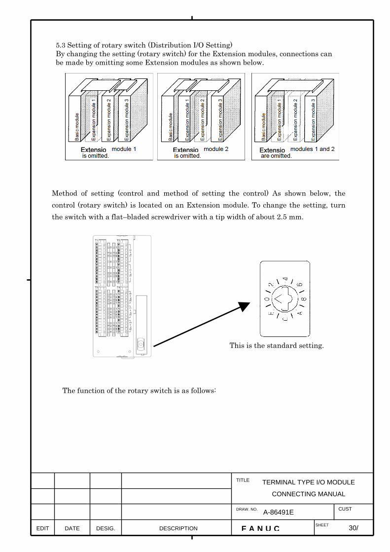
5.3 Setting of rotary switch (Distribution I/O Setting) By changing the setting (rotary switch) for the Extension modules, connections can be made by omitting some Extension modules as shown below.
Method of setting (control and method of setting the control) As shown below, the control (rotary switch) is located on an Extension module. To change the setting, turn the switch with a flat–bladed screwdriver with a tip width of about 2.5 mm.
This is the standard setting.
The function of the rotary switch is as follows:
Extensio Extensio Extensio

Examples of setting
Note) Extension module A is always mounted at thelocation of Extension module 1, so that its factory settingneed not be changed.
EDIT F A N U C SHEET
DRAW. NO. CUST
TITLE
31/ DESCRIPTION DESIG. DATE
TERMINAL TYPE I/O MODULE
CONNECTING MANUAL
A-86491E

6. How to increase the number of common terminals Mounting terminal stand on the market on the top cover of extension module, it is possible to increase the number of common terminals. Example of terminal on the market
Maker name Type case Number of maximum poles WAGO 869 series 12
Weidmuller ZDUB2.5 series 10 OSADA TWM10B series 14
Please inquire of each maker about details of the terminal.
Additional terminal
EDIT F A N U C SHEET
DRAW. NO. CUST
TITLE
32/ DESCRIPTION DESIG. DATE
TERMINAL TYPE I/O MODULE
CONNECTING MANUAL
A-86491E
33/
TERMINAL TYPE I/O MODULE
CONNECTING MANUAL
EDIT F A N U C SHEET
DRAW. NO. CUST
TITLE
DESCRIPTION DESIG. DATE
A-86491E
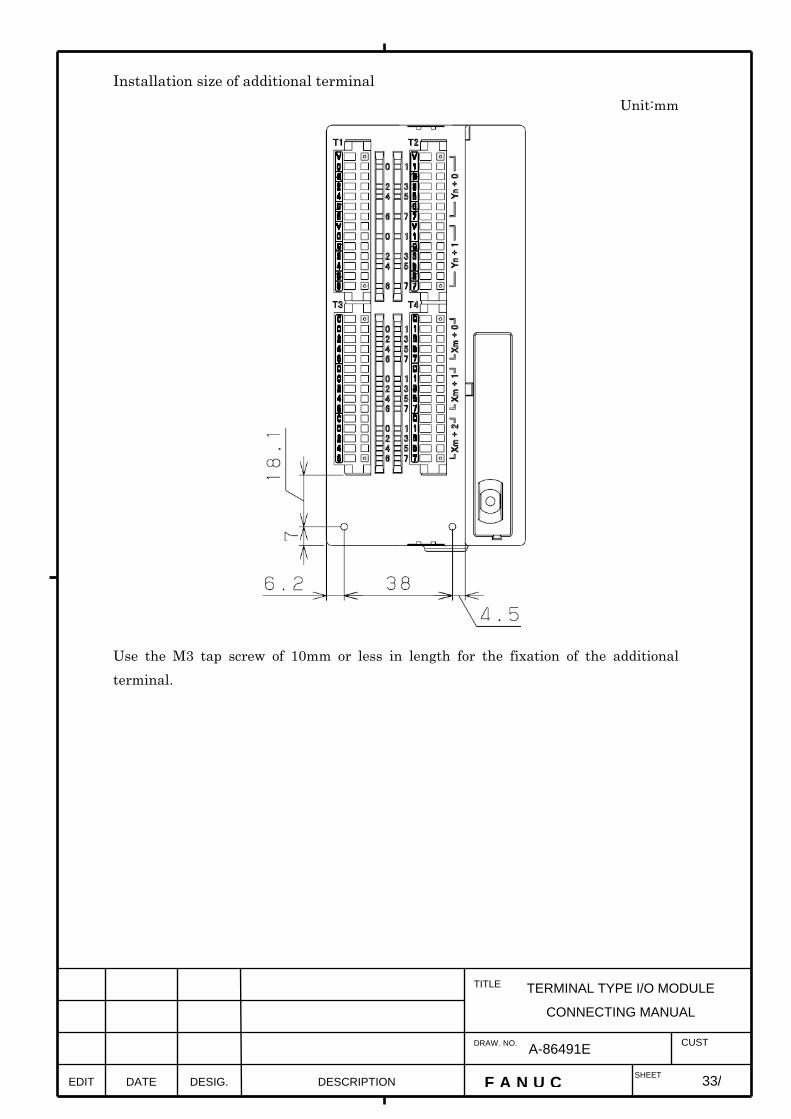
Installation size of additional terminal Unit:mm
Use the M3 tap screw of 10mm or less in length for the fixation of the additional terminal.

7. Others 7.1 DO signal reaction to a system alarm
If a system alarm occurs in a CNC using terminal type I/O module, or if I/O Link communication between the CNC and terminal type I/O module fails, all the DO signals of the I/O module are turned off. Therefore, due care must be taken when setting up the machine sequence. Also, the same phenomenon occurs if the power to the CNC or the I/O module is turned off. 7.2 Parallel DO (output signal) connection
(Basic module, Extension module A or B) A DO load current of twice the level can be obtained by connecting DO points in parallel and exercising ON/OFF control at the same time in the sequence. Namely, the maximum load current per DO point is 200mA. By connecting two DO points in parallel and turning on the two DO points at the same time, 400mA can be obtained. In this case, however, the leakage current is doubled up to 40μA when the DO points are turned off. Please assign the bit turned on and off at the same time in the same address. (For example, bit0 and bit1 in address Yn+2.)
Terminal type I/O module
LOAD
#2
34/34
TERMINAL TYPE I/O MODULE
CONNECTING MANUAL
EDIT F A N U C SHEET
DRAW. NO. CUST
TITLE
DESCRIPTION DESIG. DATE
02 06.03.10 Yamanaka Out of frame #2 is added
A-86491E