Embed Size (px)
Citation preview

TRINAMIC
® Motion Control GmbH & Co. KG
Sternstraße 67 D – 20357 Hamburg GERMANY www.trinamic.com
1 Features
The TMC457 is a high end single axis micro stepping motion controller. It adds to any microcontroller or processor with SPI
TM (SPI is Trademark of Motorola) interface. It is intended for applications, where
a precise and fast, jerk-free motion profile is desired. An encoder can be added for extremely quick and precise positioning using the internal hardware PID regulator and provides for increased reliability / fault detection. The high-resolution micro step sequencer directly controls stepper motors and piezo motors. Wide range motion control parameters eliminate any “gear switching”. The TMC457 supports linear velocity ramps and S-shaped velocity ramps. For maximum flexibility all motion control parameters (target position, target velocity, acceleration, deceleration and bow) can be changed any time during motion.
Highlights • S-shaped and linear ramps with on-the-fly alteration of all parameters • Programmable high resolution sequencer with (12 bit, 8192 entry) micro step look-up table • Incremental encoder interface with flexible up- and down scaling to match drive resolution • Fast and stable easyPID
TM PID controller
• 32 bit registers – from mHz to MHz / from nanometer to meter • SPI interface to microcontroller • Reference switch processing / virtual stop switches (programmable soft limits) • Step / direction output (with programmable timing) • Position pulse output to trigger external events • Synchronization of multiple axis via scalable step / direction input • Direct interface for TMC246/TMC249 family stepper motor drivers supports StallGuard™ (pat.) • ChopSync™ (pat. fil.) built in for best motor velocity range • Analog high resolution motor driver control via external dual 12 bit DAC • Automatic load angle limitation using encoder for stepless servo behaviour
Types of Motors • Two phase stepper motors (direct sequencer support) • PiezoMotors (direct sequencer support for PiezoMotor’s PiezoLEGS
® motor)
• Any type of motor via step/direction interface
Applications • Medical and laboratory equipment with high speed motion e.g. for liquid handling • High end placement and positioning systems / High reliability drives • Sub-micrometer positioning (piezo motors) • Active stabilization with incremental encoder and fast PID regulator
TMC457 – DATA SHEET S-profile motion controller with PID feedback
control and high resolution micro stepping
sequencer for stepper motors and piezo motors

TMC457 DATASHEET (V. 1.20 / 2013-July-11) 2
Copyright © 2008-2013 TRINAMIC Motion Control GmbH & Co. KG
Life support policy TRINAMIC Motion Control GmbH & Co. KG does not authorize or warrant any of its products for use in life support systems, without the specific written consent of TRINAMIC Motion Control GmbH & Co. KG. Life support systems are equipment intended to support or sustain life, and whose failure to perform, when properly used in accordance with instructions provided, can be reasonably expected to result in personal injury or death. © TRINAMIC Motion Control GmbH & Co. KG 2013 Information given in this data sheet is believed to be accurate and reliable. However no responsibility is assumed for the consequences of its use nor for any infringement of patents or other rights of third parties which may result from its use. Specification is subject to change without notice.

TMC457 DATASHEET (V. 1.20 / 2013-July-11) 3
Copyright © 2008-2013 TRINAMIC Motion Control GmbH & Co. KG
2 Contents
1 FEATURES ...................................................................................................................................... 1
2 CONTENTS ...................................................................................................................................... 3
2.1 Figures ...................................................................................................................................... 4 2.2 Tables........................................................................................................................................ 4
3 GENERAL DESCRIPTION .............................................................................................................. 5
4 TMC457 BLOCK DIAGRAM AND INTERFACES ........................................................................... 6
4.1 Microcontroller Interface (SPITM
) ............................................................................................... 6 4.2 Step Direction Inputs ................................................................................................................. 6 4.3 DAC (LTC2602) Interface ......................................................................................................... 6
4.3.1 Piezo Motor Driver ............................................................................................................. 6 4.4 Stepper Motor Driver Interface (TMC236, TMC239, TMC246, TMC249) ................................. 7
4.4.1 Stepper Motor Driver (high resolution micro stepping) ...................................................... 7 4.4.2 Stepper Motor Driver (low resolution micro stepping) ........................................................ 7
5 FUNCTIONAL BLOCKS AND REGISTERS ................................................................................... 8
5.1 Ramp Generator ....................................................................................................................... 8 5.2 ABN Incremental Encoder Interface .......................................................................................... 8
5.2.1 Setting the encoder to match the motor resolution: ........................................................... 9 5.3 Vector control ............................................................................................................................ 9
5.3.1 Initialization of vector control mode .................................................................................. 10 5.4 PID Controller - easyPID
TM ...................................................................................................... 10
5.5 Step Direction Output Interface ............................................................................................... 11 5.6 Step Direction Input Interface for multi axis interpolation ........................................................ 11 5.7 Reference Switch and Stop Switch Interface .......................................................................... 11 5.8 Micro Step Sequencer ............................................................................................................. 11
5.8.1 ChopSyncTM
CHOPCLK .................................................................................................. 11 5.9 Type and Version Register / Version specific notes and known bugs .................................... 12 5.10 Interrupt Controller ............................................................................................................... 12 5.11 Sine Wave Look-up Table (SIN-LUT) Access and Parameterization .................................. 13
5.11.1 Calculation of the Sine Wave Look-Up-Table to drive a Piezo Motor .............................. 13 5.11.2 Calculation of the Sine Wave Look-Up-Table to drive a Stepper Motor .......................... 13
6 REGISTER MAPPING ................................................................................................................... 14
6.1 SPI Datagram Structure .......................................................................................................... 14 6.1.1 Selection of Write / Read (WRITE_notREAD) ................................................................. 14 6.1.2 Data Alignment ................................................................................................................ 14
6.2 Register Block Structure – Register Mapping ......................................................................... 14 6.2.1 Nomenclature of Read / Write / Clear on Read / Clear on Write of Registers ................. 15 6.2.2 Time Scaling by Clock Frequency ................................................................................... 15 6.2.3 Real World Units vs. Units of the TMC457 ...................................................................... 26
7 EXAMPLES .................................................................................................................................... 27
7.1 How to Get a Motor Running ................................................................................................... 27 7.2 Set Incremental Encoder Interface Parameters ...................................................................... 27
8 NOTATION OF NUMBER SYSTEMS ........................................................................................... 28
9 PINNING, PACKAGE, AND ELECTRICAL DATA OF THE TMC457 ........................................... 29
9.1 Pinning of TMC457.................................................................................................................. 29 9.1.1 Pull-Up / Pull-Down Resistances ..................................................................................... 32 9.1.2 Blocking Capacitors ......................................................................................................... 32
9.2 Package Outlines and Dimensions ......................................................................................... 33

TMC457 DATASHEET (V. 1.20 / 2013-July-11) 4
Copyright © 2008-2013 TRINAMIC Motion Control GmbH & Co. KG
9.2.1 Fine Pitch BGA Package with 144 Balls (FBGA144) of TMC457-BC .............................. 33
10 MICRO CONTROLLER INTERFACE (SPI) ............................................................................... 34
11 CHARACTERISTICS .................................................................................................................. 35
12 LITERATURE ............................................................................................................................. 36
13 REVISION HISTORY .................................................................................................................. 37
2.1 Figures Figure 1 : Functional Block Diagram of the TMC457 ............................................................................... 5 Figure 2 : TMC457 with Piezo Motor Interface ........................................................................................ 6 Figure 3 : High Resolution Micro Stepping Configuration ........................................................................ 7 Figure 4 : Stepper Motor Driver Configuration (SPI) ................................................................................ 7 Figure 5 : Outline of ABN Signals of an Incremental Encoder ................................................................. 8 Figure 6 : Incremental Encoder Signals Outline (AB w/o clear pulse N) ............................................... 28 Figure 7 : Package Outline Drawing FBGA144 – (JEDEC MO-192 VAR DAD-1) ................................. 33 Figure 8 : Timing Diagram of the Serial Micro Controller Interface ....................................................... 34 Figure 9 - General IO Timing Parameters ............................................................................................. 35
2.2 Tables Table 1 : PWM frequency calculation for ChopSync
TM .......................................................................... 12
Table 2: TMC457-BC Pin Out ................................................................................................................ 32 Table 3 : Dimensions of FBGA144 (Note: BSC = Basis Spacing Between Centers) ............................ 33 Table 4: Timing Characteristics of the Micro Controller Serial Peripheral Interface (SPI) ..................... 34 Table 5 - Absolute Maximum Ratings .................................................................................................... 35 Table 6 – DC Ccharacteristics Operating Conditions ............................................................................ 35 Table 7 - Power Dissipation ................................................................................................................... 35 Table 8 - General IO Timing Parameters .............................................................................................. 35
TMC457 DATASHEET (V. 1.20 / 2013-July-11) 5
Copyright © 2008-2013 TRINAMIC Motion Control GmbH & Co. KG
3 General Description
The TMC457 has been designed with TRINAMIC's background of more than 10 years of dedicated motion control ICs for stepper motors, like the 6 axis controller TMC406, the low cost 3 axis controller TMC428 and the high end controller TMC453 with its compatible successor TMC454. While there lie 10 years of development and experience between the TMC453 and the TMC457, the basic features look similar, but a lot of ideas, application know-how and customer feedback have been evaluated, sorted and flown into the design. The intention in creating the TMC457 was to provide a motion controller that provides superior performance, which can hardly be achieved by software in a processor system, while providing a very easy-to-use interface to the programmer, which looks similar to the peripherals found in a microcontroller. The electronic gear shift / pre-scaling found in our other motion controllers was eliminated by extending position and velocity registers to 32 bits. This direct control makes it easy to use the full range and precision of parameter setting. The easyPID™ closed loop PID regulator eases the achievement of control loop stability by providing a programmable hysteresis. Some features found in the TMC453 and TMC428 have been streamlined, to make them easier to use and some options have been removed, like the programmable sequencer for many different motor types, bearing in mind the most common applications.
SPI bus
interface
Interface
Section
TMC457I
RES
ICLK
IENABLE
CLK
RES
INSCS
ISCK
ISDI
OSDO
Host CPU SPI
InterfaceRegister
Block
Interrupt
controlO
NINT
Stop input
processing
& virtual
stop
switches
S-Ramp
generator
Trapezoid
Ramp
generator
ISTOPL
ISTOPR
Pulse
generator
OSTEP_OUT
ODIR_OUT
ISTEP_IN
IDIR_IN
OXSTEP_OUT
OHIRES_OUT
OSTDBY_OUT
Position
Counter
Position
compareO
POSCOMP
Output
Pulse
generator
easyPID
PID
controller
Encoder
Scaler &
Counter
v
control &
status
STEP DIR
Prescaler
target
quadrature
decoder
100n
100n
GN
D
+1.5
V
+3.3
V
+3
.3V
+1
.5V
one capacitor
per supply pin
OPHA
OPHB
ONCS_DAC
OSCK_DAC
OSDO_DAC_A
2 phase
stepper &
piezo
sequencer
OSDO_DAC_B
TMC24x
SPI
interface
ONCS_DRV
OSCK_DRV
OSDO_DRV
ISDI_DRV
IENC_A
IENC_B
IENC_N
Microstep
RAM
8192*12
STEP/
DIR
SequencerMotion profile
generation
Encoder
Optional
Incremental
Encoder
PID
Stop /
Reference
Switches
Optional Step/
Dir Input
Step/Dir Output
Classic stepper
driver
Analog control of
Stepper / Piezo
via DAC
(LTC2622)
TMC246 /
TMC249 stepper
driver
ChopSync OChopClk synchronized
chopper clock
INANA_SPI
IPZO_EN
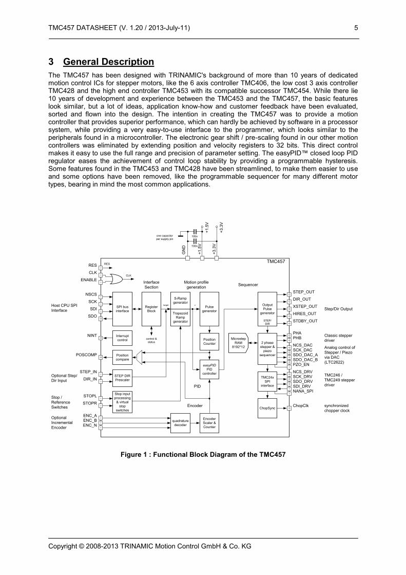
Figure 1 : Functional Block Diagram of the TMC457

TMC457 DATASHEET (V. 1.20 / 2013-July-11) 6
Copyright © 2008-2013 TRINAMIC Motion Control GmbH & Co. KG
4 TMC457 Block Diagram and Interfaces
Figure 1 shows the block diagram of the TMC457 motion controller. The TMC457 is equipped with a SPI interface for communication with the microcontroller. It uses a fixed data length of 40 bit – 8 bit address and 32 data. The TMC457 has a driver SPI to directly control the TRINAMIC stepper motor drivers TMC236, TMC239, TMC246, and TMC249. It supports processing of StallGuard information to emulate a reference switch, when using TMC246 or TMC249. The TMC457 has step direction input and step direction outputs as well to allow the control of step direction power stages (like the TMC332) or for external monitoring of motion by step pulse counting. For high precision micro stepping the TMC457 is equipped with a DAC interface for LTC2602. This allows control of the TMC236 family with extended microstep resolution or control of external power drivers with the classical analog control. An incremental encoder interface is added for processing incremental encoders with digital quadrature signal outputs (ABN). The position available from the quadrature signal decoder is directly available as an input for the PID position regulator. The PID regulator is for position stabilization also during motion. The PID regulator runs at an update rate of 100kHz and thus provides fastest response times.
4.1 Microcontroller Interface (SPITM
) The SPI for communication with the microcontroller to set motion control parameters (velocity, acceleration, bow, …) of the TMC457 and to send motion command for positioning (set target position) and continuous motion applications (set velocity).
4.2 Step Direction Inputs In addition to the SPI for micro controller communication with the TMC457, the motion can be controlled externally via the step direction inputs STEP_IN and DIR_IN.
4.3 DAC (LTC2602) Interface The DAC interface directly controls LTC2602 from Linear Technologies to generate analog output signals (two channels for micro stepping of bipolar two phase stepper motors) and four channels as required for PiezoLEGS motors from the company Piezo-Motors.
4.3.1 Piezo Motor Driver The power four required power stages of the driver for the piezoelectric motor (PiezoLEGS) must be able to drive a 100nF capacitance at 3kHz with an amplitude of 48V each. A power stage with these capabilities is realized for the TMC457 evaluation board.
V_REF
PZO_EN
TMC457
DAC A
DAC B
Control Logic
LTC2622 2 x DAC 12 Bit
Vout A
Vout B
REF
nCS_LD
SCK
SDI
GND
+3.3V VCC
GND
DAC A
DAC B
Control Logic
LTC2622 2 x DAC 12 Bit
Vout A
Vout B
REF
nCS_LD
SCK
SDI
GND
+3.3V VCC
GND
M1
M2
M3
M4
# 1
# 2 (for Piezo-Motor)
+3.3V
P1
P2
P3
P4
Po
we
r S
tag
e A
mp
lifi
er
SCK_DAC
SDO_DAC_A
SDO_DAC_B
LTC2602 Interface
nCS_DAC
Figure 2 : TMC457 with Piezo Motor Interface
TMC457 DATASHEET (V. 1.20 / 2013-July-11) 7
Copyright © 2008-2013 TRINAMIC Motion Control GmbH & Co. KG
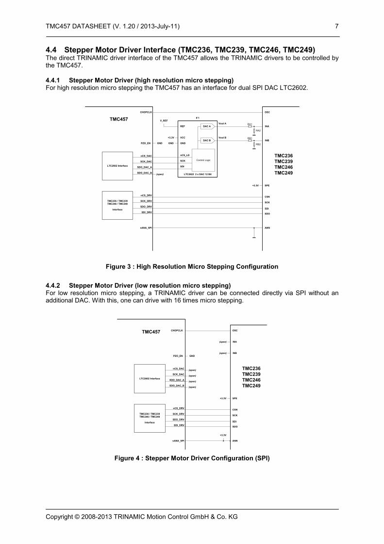
4.4 Stepper Motor Driver Interface (TMC236, TMC239, TMC246, TMC249) The direct TRINAMIC driver interface of the TMC457 allows the TRINAMIC drivers to be controlled by the TMC457.
4.4.1 Stepper Motor Driver (high resolution micro stepping) For high resolution micro stepping the TMC457 has an interface for dual SPI DAC LTC2602.
V_REF
PZO_EN
SCK_DAC
SDO_DAC_A
SDO_DAC_B
TMC457
LTC2602 Interface
DAC A
DAC B
Control Logic
LTC2622 2 x DAC 12 Bit
Vout A
Vout B
REF
nCS_LD
SCK
SDI
GND
+3.3V VCC
GND
INA
INB
# 1
GND
nANA_SPI
nCS_DAC TMC236
TMC239
TMC246
TMC249
TMC236 / TMC239
TMC246 / TMC249
Interface
nCS_DRV
SDO_DRV
SCK_DRV
SDI_DRV
(open)
ANN
CSN
SCK
SDI
SDO
SPE+3.3V
CHOPCLK OSC
RA1
RA2
RB1
RB2
Figure 3 : High Resolution Micro Stepping Configuration
4.4.2 Stepper Motor Driver (low resolution micro stepping) For low resolution micro stepping, a TRINAMIC driver can be connected directly via SPI without an additional DAC. With this, one can drive with 16 times micro stepping.
PZO_EN
TMC457
INA
INB
GND
nANA_SPI
TMC236
TMC239
TMC246
TMC249(open)
ANN
CSN
SCK
SDI
SDO
SPE+3.3V
(open)
(open)
+3.3V
(open)
(open)
(open)
CHOPCLK OSC
SCK_DAC
SDO_DAC_A
SDO_DAC_B
LTC2602 Interface
nCS_DAC
TMC236 / TMC239
TMC246 / TMC249
Interface
nCS_DRV
SDO_DRV
SCK_DRV
SDI_DRV
Figure 4 : Stepper Motor Driver Configuration (SPI)

TMC457 DATASHEET (V. 1.20 / 2013-July-11) 8
Copyright © 2008-2013 TRINAMIC Motion Control GmbH & Co. KG
5 Functional Blocks and Registers
5.1 Ramp Generator The ramp generator is the heart of the motion controller. It runs either ramp with linear velocity profile or ramp with s-shape velocity profile. The selection is done by the bow parameter. Setting bow to 0 selects linear velocity profile. Linear ramps perform the quickest motion, by using the maximum available acceleration at all times. But, since the acceleration becomes switched on and off abruptly, system resonances can occur. They appear like an additional load on the motor, thus reducing the available useful portion of motor torque. Further, system resonances need some time to fade away, and this can costs valuable system time, if a complete stand still is required, before other actions can start. With the S-shaped ramp, resonances can be reduced. However, it is advised to choose the bow parameter as high as possible, in order to optimize positioning time. The ramp generator provides four modes of operation: […] It should be noted, that the choice of the microstep resolution directly influences the complete ramp generator parameter settings, because a higher microstep resolution means a higher end velocity setting, and thus a higher acceleration and a higher bow parameter to yield the same results. This way, the settings are scaled in a huge range, e.g. when changing between fullstep and highest resolution microstep. Attention: At all times, all parameters may be changed, but it should be noted, that unexpected results may occur, when changing the bow parameter to a lower value during an acceleration phase, or when changing the acceleration or deceleration parameter to a lower value. In these cases, the maximum positioning velocity, respectively the target position could be exceeded, in case the new values do not allow decelerating quickly enough. Even an overrun of the register value could occur and lead to unexpected results. Under normal circumstances, the bow parameter will be fixed in an application.
A
B
t
position -4 -3 -2 -1 0 5 64321 7
N
Figure 5 : Outline of ABN Signals of an Incremental Encoder
5.2 ABN Incremental Encoder Interface The TMC457 is equipped with an incremental encoder interface for ABN encoders that gives positions via digital incremental quadrature signals (usually named A and B) and a clear signal (usually named N for null of Z for zero). The N signal can be used to clear a position. It might be necessary to disable the clearing of the encoder position after the first N signal event because the encoder gives this signal once for each revolution and for most applications a motor turns more than one revolution. The encoder constant named enc_const is added or subtracted on each position change of the quadrature signals AB of the incremental encoder. The encoder constant enc_const represents an unsigned fixed point number (16.16) to facilitate the generic adaption between motors and encoders. In

TMC457 DATASHEET (V. 1.20 / 2013-July-11) 9
Copyright © 2008-2013 TRINAMIC Motion Control GmbH & Co. KG
decimal mode, the lower 16 bit represent a number between 0 and 9999. This is especially important for piezo motors (PiezoLEGS) because they do not have a fixed step length they achieve their very high positioning precision in the range of nanometers via closed loop control together with a position encoder. For stepper motors equipped with incremental encoders the fixed number representation allows very comfortable parameterization. Additionally, gear can easily be taken into account. The encoder counter named x_enc holds the current determined encoder position. Different modes concerning handling of the signals A, B, and N take active low and active high signals of usual incremental encoders into account. For details please refer to the register mapping section 6 Register Mapping, page 14 ff. The register enc_status holds the status concerning event of the ABN signals. The register enc_latch stores the actual encoder position on an N signal event. The register x_latch stores the position while a reference switch event occurs. A register named enc_warn_dist (encoder warning distance) is used to generate an interrupt via the TMC457 interrupt controller if the distance between encoder position and actual position is larger then enc_warn_dist. The calculated error pid_e is available from the PID controller unit. Therefore, the PID controller needs to be enabled.
5.2.1 Setting the encoder to match the motor resolution: Encoder example settings for motor parameters: 2048 µsteps, 200FS 409600 / U Factor = FS*µS / encoder resolution
Encoder example settings for a 200 fullstep motor with 2048 microsteps
Encoder resolution required encoder factor comment
200 2048
360 1137,7778 = 74565404,4444 / 2^16 = 11377777,7778 / 10000
No exact match possible!
500 819,2 = 53687091,2 / 2^16 = 8192000 / 10000
exact match with decimal setting
1000 409,6 exact match with decimal setting
1024 400
3600 113,7778 No exact match possible!
4000 102,4 exact match with decimal setting
4096 100
8192 50
16384 25
32768 12.5
5.3 Vector control The vector control unit allows a load angle based motor control. This makes the motor behave like a servo motor, i.e. it can be overloaded or stopped, and will later on catch up again, using the PID regulator. Therefore, be careful to also activate the PID regulator! Vector control is only possible using binary encoder resolutions, because no decimal setting is available. Low resolution decimal encoders still give a match.

TMC457 DATASHEET (V. 1.20 / 2013-July-11) 10
Copyright © 2008-2013 TRINAMIC Motion Control GmbH & Co. KG
Vector control example settings for a 200 fullstep motor
Encoder resolution required vector encoder factor venc_us_const
512 25 1600
1024 12.5 800
2048 6.25 400
4096 3.125 = 3 1/8 200
8192 1.5625 = 1 9/16 100
16384 0.78125 = 25/32 50
32768 0.390625 = 25/64 25
A 400 fullstep motor needs the double setting Different load angle limits above 90° allow for field weakening operation, which gives a faster motor operation.
5.3.1 Initialization of vector control mode A precise initialization of the vector control mode is critical for best functionality. Also, the encoder needs to have an absolute precision, which is at least ½ fullstep of the motor. For a newly assembled drive, an initial initialization is necessary. This initialization requires that the motor does not see any mechanical load during initialization. Later on, the vector control can be initialized with a stored offset from the initial initialization, using absolute position information, for example based on the encoder N channel. For initial initialization, the following procedure can be followed: The actual encoder position venc_us_pos needs to be initialized for vector control. The position must match selected microstep_adr bits, when the motor is unloaded in its exact position. This for example can be accomplished, by switching the motor to a high standby torque after power on. Directly after a power on, all microstep_adr bits are zero. Now, the motor will be in the exact zero position, as long as it sees no mechanical load. Therefore, now the venc_us_pos can be initialized with zero, in order to match the encoder angle to the electrical angle of the motor. When the absolute position of the encoder is known, the vector control register venc_us_pos can be initialized based on this information. Therefore, the encoder needs to be read out, or the N channel needs to be found, and afterwards the stored offset can be added to the absolute position and be written to venc_us_pos. Be sure to do this in a high priority procedure, because the encoder should not advance a step in the meantime. If this cannot be guaranteed, a check and iteration should be done.
5.4 PID Controller - easyPIDTM
The PID (Proportional Integral Differential) controller calculates a velocity v based on a position difference error pid_e = enc_x – x_actual where enc_x is the actual position- the real mechanical position -determined by the incremental encoder interface and x_actual is the actual position of the micro step sequencer –the position the TMC457 assumes to be the actual one. With this, the TMC457 moves with this (signed) velocity v until the actual position- measured by the incremental encoder –match. The velocity v to minimize the error e is calculated by
)()()(0
tedt
dDdtteItePv
t
.
The motor moves with this velocity v = pid_v_actual until the error e(t) vanishes resp. falls below a programmed limit – the hysteresis pid_tolerance. Primary, the PID regulator is parameterized by its basic parameter P, I, D represented by registers pid_p, pid_i, pid_d. Setting pid_d = 0 makes a PI regulator, additionally setting pid_i = 0 makes a P regulator. For micro controller interaction, the parameter pid_dv_cpu is added to the pid_v_actual. The readable register pid_dv_clip holds the actual value of clipping done by the PID controller of the TMC457.

TMC457 DATASHEET (V. 1.20 / 2013-July-11) 11
Copyright © 2008-2013 TRINAMIC Motion Control GmbH & Co. KG
Due to constraints of practical real word application, the integer part of the PID regulator can be clipped to a limit named pid_iclip. Without this, the integral part of the PID regulator pid_isum increases with each time step by pid_i*pid_e as long as the motor does not follow. The actual error can be read out from register pid_e. The integration over time of the error e is done with a fixed clock frequency of fPID_INTEGRAL[Hz] = fCLK[Hz] / 128. The time scaling for the deviation with respect to time of the error is controlled by the register named pid_clk_div. A stabilization of the target position by programmable hysteresis is integrated to avoid oscillations of regulation when the actual position is close to the real mechanical position. The PID controller of the TMC457 is fast – programmable up to approximate 100kHz update rate at fCLK = 16 MHz of the TMC457 – so that it can be used during motion to stabilized the motion. The parameterization of the PID controller of the TMC457 occurs in a direct way. Due to this, it is named easyPID
TM. Nevertheless,
the parameterization of a PID controller might need a detailed knowledge of the application and the dynamic of the mechanics that is controlled by the PID controller. Additionally, a special control register allows software interaction for additional feedback control algorithms that can be implemented within the micro controller used to parameterize the TMC457.
5.5 Step Direction Output Interface The TMC457 is equipped with step direction outputs (STEP, OUT). In Addition, it is equipped with a so called X_STEP output. A pulse on this output represents a number of (micro) steps. It is configured by the register named pulse_xstep_div. The TMC457 is able to generate step pulses with up to its clock frequency fCLK[Hz]. Because a step frequency in the range of the clock frequency of the TMC457 might be too high for usual step direction drivers, an additional step output named X_STEP (extended step) is available. The X_STEP represents a number of steps to be done at a lower frequency. The threshold that selects between step pulses and extended step pulses is programmable. This can be parameterized to give full steps on the XSTEP output of the TMC457.
5.6 Step Direction Input Interface for multi axis interpolation The TMC457 is equipped with step direction inputs (STEP_IN, DIR_IN). This allows using the TMC457 with an external ramp generator. A number of TMC457 can be synchronized by interconnecting the step direction inputs and outputs via a switch matrix. One TMC457 is used as master and its step and direction output is fed to the other TMC457. They can be programmed to follow the master pulses scaled by the 15 bit factor sd_scale (and sign). This way, multi-axis interpolation can be realized. The slave motion thus always is equal or slower than the master. When programming the master axis, the maximum allowed acceleration and velocity values of the slave axis have to be considered. The step input is sampled once per system clock. Thus, the maximum input frequency is equal to the half system clock frequency. Please remark, that this also limits the master velocity during interpolated moves.
5.7 Reference Switch and Stop Switch Interface The TMC457 is equipped with reference switch that can be programmed for automatic actions. For details please refer to the register mapping section 6 Register Mapping, page 14 ff. The reference switch inputs are available to store a position on a reference switch event. Additionally, these inputs can be enabled to force a stop.
5.8 Micro Step Sequencer The micro step sequencer can be programmed for different micro step resolutions. The sequencer controls the mixed decay feature of TRINAMIC stepper motor drivers. Current scaling is also done under control of the sequencer. When using TMC246 or TMC249 the StallGuard
TM threshold is under
control of the sequencer. A readable register holds the TRINAMIC stepper motor driver status bits and diagnosis bits.
5.8.1 ChopSyncTM
CHOPCLK
To use the ChopSyncTM
feature together with a TRINAMIC stepper motor driver the output CHOPCLK of the TMC457 has to be connected to the PWM oscillator input OSC of the TRINAMIC stepper motor driver (TMC236, TMC239, TMC246, or TMC249) – without a capacitor at the OSC input. The recommended chopper frequency fOSC for the TRINAMIC stepper motor driver is 36kHz. The chopper frequency should not be below 25kHz and must be lower than 50kHz. The chopper frequency is programmed via the register chop_clk_div.

TMC457 DATASHEET (V. 1.20 / 2013-July-11) 12
Copyright © 2008-2013 TRINAMIC Motion Control GmbH & Co. KG
Warning: A chopper clock signal with a too high frequency might damage the stepper motor driver due to dynamic power dissipation overload.
fCLK[Hz] fOSC[Hz] chop_clk_div
16.000.000 36.000 0x1BC (=444)
25.000 0x280 (=640)
8.000.000 36.000 0x0DE (=222)
25.000 0x140 (=320)
fCLK[Hz] fOSC[Hz] fCLK[Hz] / fOSC[Hz]
Table 1 : PWM frequency calculation for ChopSyncTM
5.9 Type and Version Register / Version specific notes and known bugs The type of the controller and its version can be read out from a register. For the TMC457 version 1.02 one gets 0x00457102 reading the type and version register. This allows hardware detection. Reading the version allows handling of different version by a single software version.
Version Bug Description and workaround
1.02 AMAX lower limit with linear ramps
When using linear ramps, setting AMAX to a value lower than 128 results in a strange positioning behavior, when AMAX and DMAX differ.
This is due to an internal rounding which results in AMAX being used for deceleration rather than DMAX or vice versa.
This bug will be corrected in future versions.
Workaround:
Use AMAX values above 128, when AMAX and DMAX are required to be different. AMAX values below 128 are typically only required, when working with low microstepping resolutions.
Alternative: Use S-shaped ramps.
-1.03 Stop switches do not become disabled at move in opposite direction while actual velocity is zero
When the motor becomes stopped by a stop switch, a movement into the opposite direction is not possible without disabling the stop switch.
The reason is that the stop switches are active in any direction when velocity is zero.
This bug will be corrected in future versions.
Workaround:
Disable stop switch when moving into opposite direction.
5.10 Interrupt Controller The interrupt controller is programmable for different conditions. If an interrupt condition occurs the open drain output nINT is pulled to low (activated) if the interrupt mask for the corresponding interrupt condition is enabled.

TMC457 DATASHEET (V. 1.20 / 2013-July-11) 13
Copyright © 2008-2013 TRINAMIC Motion Control GmbH & Co. KG
5.11 Sine Wave Look-up Table (SIN-LUT) Access and Parameterization The TMC457 is equipped with an internal RAM (8192 addresses x 12 bit data) to hold a sine wave look-up table for micro stepping. This look-up table has to be initialized first after power up of the TMC457. Depending on the type of motor, a dedicated sine wave table has to be written into the internal RAM of the TMC457. For both, 8192 values of 12 bit integer have to be calculated. The sine LUT RAM is accesses via two register addresses, one for read and one for write.
Important Hint: When reading data from RAM, the read data are valid with the next read access. So, the read data are pipelined with a delay of one SPI datagram.
5.11.1 Calculation of the Sine Wave Look-Up-Table to drive a Piezo Motor
y(x) = 4096 + 4095 * sin(2* x/8192 – 2*/8) with x = 0, 1, 2, 3, …, 8189, 8190, 8191.
5.11.2 Calculation of the Sine Wave Look-Up-Table to drive a Stepper Motor
y(x) = abs( 4095 * sin(2* x/8192) ) with x = 0, 1, 2, 3, …, 8189, 8190, 8191. With offset, to adjust current zero crossing, the formula becomes
y(x) = offset + abs( (4095 - offset) * sin(2* x/8192) ) with x = 0, 1, 2, 3, …, 8189, 8190, 8191. The offset has a theoretical range of 0 to 4094. For a practical application, the offset will lie between 0 and 100. When using current scaling, the offset also becomes scaled down – this may be needed to be taken into account!

TMC457 DATASHEET (V. 1.20 / 2013-July-11) 14
Copyright © 2008-2013 TRINAMIC Motion Control GmbH & Co. KG
6 Register Mapping
6.1 SPI Datagram Structure The TMC457 uses 40 Bit SPI
TM (Serial Peripheral Interface, SPI is Trademark of Motorola) datagrams
for communication with a microcontroller. Microcontrollers which are equipped with hardware SPI are typically able to communicate with integer multiples of 8 bit. Each datagram sent to the TMC457 is composed of an address byte followed by four data bytes. This allows direct 32 bit data word communication with the register set of the TMC457. Each register is accessed via 32 data bits even if it uses less than 32 data bits. For simplification, each register is specified by a one byte address, where the reading address is given with the most significant bit = '0'. For a write access, the most significant bit of the address byte is '1'. Most registers are write only registers, some can be read additionally, and there are also some read only registers.
6.1.1 Selection of Write / Read (WRITE_notREAD) The read and write selection is controlled by the MSB of the address byte (bit 39 of the SPI datagram). This bit is '0' for read access and '1' for write access. So, the bit named W is a WRITE_notREAD control bit. The active high write bit is the MSB of the address byte. So, 0x80 has to be added to the address for a write access. Example: For a read access to the register (x_actual) with the address 0x01, the address byte has to be set to 0x01. For a write access to the register (x_actual) with the address 0x01, the address byte has to be set to 0x80 + 0x01 = 0x81. For read access, the data bit might have any value ('-'). So, one can set them to '0'. READ x_actual datagram 0x01000000000;
WRITE x_actual := 0x89ABCDEF; datagram 0x8189ABCDEF;
TMC457 SPI Datagram Structure
MSB (transmited first) 40 bit LSB (transmitted last)
39 ... ... 0
8 bit ADDRESS 32 bit DATA
39 ... 32 31 ... 0
RW + 7 bit
ADDRESS 8 bit DATA 8 bit DATA 8 bit DATA 8 bit DATA
39 / 38 ... 32 31 ... 24 23 ... 16 15 ... 8 7 ... 0 W 38...32 31...28 27...24 23...20 19...16 15...12 11...8 7...4 3...0
39
38
37
36
35
34
33
32
31
30
29
28
27
26
25
24
23
22
21
20
19
18
17
16
15
14
13
12
11
10
9 8 7 6 5 4 3 2 1 0
6.1.2 Data Alignment All data are right aligned. Some registers represent unsigned (positive) values, some represent integer values (signed) as two’s complement numbers, single bits or groups of bits are represented as single bits respectively as integer groups.
6.2 Register Block Structure – Register Mapping All parameterizations take place by register writes. The access to the registers is via SPI. The ramp generator register set enfolds basic motion control parameters, a ramp generator register set, an incremental encoder register set, a PID controller register set – named easyPID
TM, a step direction
output configuration register set, a reference switch configuration register set, a micro step sequencer configuration register, a type & version register, an interrupt configuration register, and a sine wave look-up table (LUT) RAM port register.

TMC457 DATASHEET (V. 1.20 / 2013-July-11) 15
Copyright © 2008-2013 TRINAMIC Motion Control GmbH & Co. KG
6.2.1 Nomenclature of Read / Write / Clear on Read / Clear on Write of Registers Units are written in are given in brackets, e.g. [micro steps]. Read only registers are designated by R. Read only registers with automatic clear (C) on read are designated by R+C. Registers that are cleared on write are designated by W+C. Write only registers are designated by W.
6.2.2 Time Scaling by Clock Frequency Time is scaled by the the clock frequency of the TMC457. This scales velocity, acceleration, and bow. So, velocity is given in unit [micro steps per time] and not as [micro steps per second], acceleration is given in unit [micro steps per time^2] and not unit [micro steps per second^2]. Formulas for the conversion into units based on time in seconds is given in section 0, page 26.
TMC457 DATASHEET (V. 1.20 / 2013-July-11) 16
Copyright © 2008-2013 TRINAMIC Motion Control GmbH & Co. KG
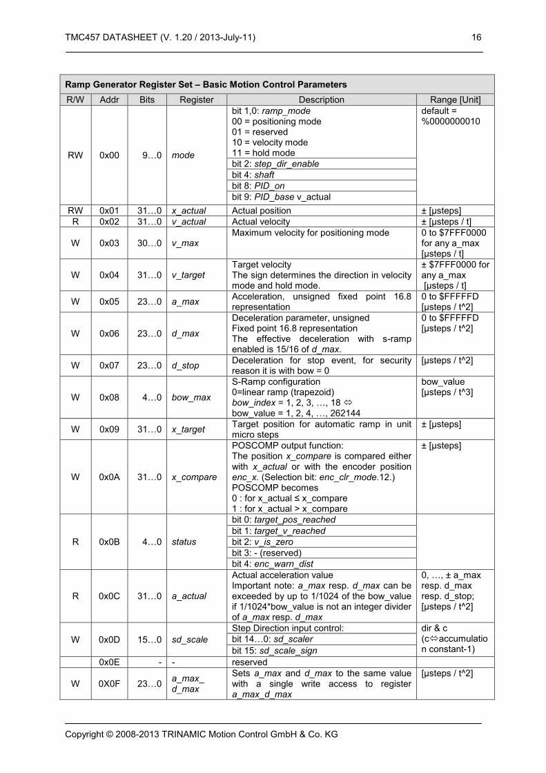
Ramp Generator Register Set – Basic Motion Control Parameters
R/W Addr Bits Register Description Range [Unit]
RW 0x00 9…0 mode
bit 1,0: ramp_mode 00 = positioning mode 01 = reserved 10 = velocity mode 11 = hold mode
default = %0000000010
bit 2: step_dir_enable
bit 4: shaft
bit 8: PID_on
bit 9: PID_base v_actual
RW 0x01 31…0 x_actual Actual position ± [µsteps]
R 0x02 31…0 v_actual Actual velocity ± [µsteps / t]
W 0x03 30…0 v_max Maximum velocity for positioning mode 0 to $7FFF0000
for any a_max [µsteps / t]
W 0x04 31…0 v_target Target velocity The sign determines the direction in velocity mode and hold mode.
± $7FFF0000 for any a_max [µsteps / t]
W 0x05 23…0 a_max Acceleration, unsigned fixed point 16.8 representation
0 to $FFFFFD [µsteps / t^2]
W 0x06 23…0 d_max
Deceleration parameter, unsigned Fixed point 16.8 representation The effective deceleration with s-ramp enabled is 15/16 of d_max.
0 to $FFFFFD [µsteps / t^2]
W 0x07 23…0 d_stop Deceleration for stop event, for security reason it is with bow = 0
[µsteps / t^2]
W 0x08 4…0 bow_max
S-Ramp configuration 0=linear ramp (trapezoid) bow_index = 1, 2, 3, …, 18 bow_value = 1, 2, 4, …, 262144
bow_value [µsteps / t^3]
W 0x09 31…0 x_target Target position for automatic ramp in unit micro steps
± [µsteps]
W 0x0A 31…0 x_compare
POSCOMP output function: The position x_compare is compared either with x_actual or with the encoder position enc_x. (Selection bit: enc_clr_mode.12.) POSCOMP becomes 0 : for x_actual ≤ x_compare 1 : for x_actual > x_compare
± [µsteps]
R 0x0B 4…0 status
bit 0: target_pos_reached
bit 1: target_v_reached
bit 2: v_is_zero
bit 3: - (reserved)
bit 4: enc_warn_dist
R 0x0C 31…0 a_actual
Actual acceleration value Important note: a_max resp. d_max can be exceeded by up to 1/1024 of the bow_value if 1/1024*bow_value is not an integer divider of a_max resp. d_max
0, …, ± a_max resp. d_max resp. d_stop; [µsteps / t^2]
W 0x0D 15…0 sd_scale
Step Direction input control: dir & c (caccumulation constant-1)
bit 14…0: sd_scaler
bit 15: sd_scale_sign
0x0E - - reserved
W 0X0F 23…0 a_max_ d_max
Sets a_max and d_max to the same value with a single write access to register a_max_d_max
[µsteps / t^2]

TMC457 DATASHEET (V. 1.20 / 2013-July-11) 17
Copyright © 2008-2013 TRINAMIC Motion Control GmbH & Co. KG
0x00: mode - Ramp Generator Register
R/W Bit Function Value Description
RW 1,0 ramp_ mode
00 positioning mode
01 reserved
10 velocity mode (default mode on RESET)
11 hold mode (sets v_actual equal to v_target)
RW 2 step_dir_ enable
0 step direction inputs are ignored
1
The step and direction inputs (STEP_IN, DIR_IN) become scaled by sd_scale. In this mode, x_target becomes directly controlled by the scaled step inputs. In order to allow the motor to directly follow the control signals, set to positioning mode and set a high acceleration value a_max_d_max with bow set to zero.
RW 4 shaft 0 Normal direction of the output pulse generator
1 Inverts the direction of the output pulse generator
RW 8 PID_on 0 PID controller is completely off, all values are frozen. The output pulse generator is fed by v_actual directly.
1 PID controller is on. This mode also allows access to the PID error pid_e, which is required for a number of other functions. For normal operation, also set PID_base flag to v_actual base.
RW 9 PID_base 0 The pulse generator output is controlled by the PID calculation result only. The motor will not move, if PID result is zero.
1 PID output base is v_actual. The PID result is added to the velocity output generated by the ramp generator and becomes clipped to 2^31-1.
0x08: bow_max - Ramp Generator Register
R/W Bit Function Value Description
W 4…0 bow_index 0 The ramp generator uses trapezoid ramps. This corresponds to an infinite bow value.
1 to 18
Bow for s-shaped ramps in logarithmic representation. A high bow value leads to a shorter bow phase. The bow_value is added with 1/1024 fCLK[Hz] to acceleration a_actual up to the value set by a_max for acceleration resp. d_max for deceleration. bow_value = 2^(bow_index-1) bow_index = 1, 2, 3, …, 18 bow_value = 1, 2, 4, …, 262144 Attention on bow setting: The resulting bow_value must not exceed A_MAX or D_MAX setting. Otherwise oscillations may result.
0x0b: status - Ramp Generator Register
R/W Bit Function Value Description
R 0 target_pos_reached
1 Signals that the motor has stopped at the target position (x_actual=x_target), or at a position determined by PositionLimit_L or PositionLimit_R.
1 target_v_ reached
1 Signals that v_actual has reached v_target, respectively v_max during an automatic ramp.
2 v_is_zero 1 Signals that the motor has stopped.
3 - - Unused (reserved)
4 enc_warn_ dist_status
1 Signals that the deviation between encoder position and actual ramp position exceeds the warning threshold enc_warn_dist.

TMC457 DATASHEET (V. 1.20 / 2013-July-11) 18
Copyright © 2008-2013 TRINAMIC Motion Control GmbH & Co. KG
0x0D: sd_scale - Ramp Generator Register
R/W Bit Function Value Description
W 14...0 sd_scaler x Each step input pulse counts up resp. down x_target by (x+1) / (2^15)
15 sd_scale_ sign
0 Count up when direction input is positive
1 Count down when direction input is positive
Encoder Register Set
R/W Addr Bits Register Description Range [Unit]
W 0x10 31…0 enc_const
Accumulation constant, 16 bit integer part, 16 bit fractional part enc_x accumulates +/- enc_const / (2^16* enc_x) (binary) or +/- enc_const / (10^4* enc_x) (decimal) To switch between decimal and binary setting, see enc_mode bit 13. Use the sign, to match rotation direction!
binary: ± [µsteps/2^16] ±(0…32767.0…65535) decimal: ±(0…32767.0…9999) default = 1.0 (=65536)
RW 0x11 31…0 enc_x Actual encoder position ± [µsteps]
W 0x12 12…0 enc_mode
bit 0 : pol_A
bit 1 : pol_B
bit 2 : pol_N
bit 3 : ignore_AB
bit 4 : clr_cont
bit 5 : clr_once
bit 6 : pos_edge
bit 7 : neg_edge
bit 8 : clr_enc_x
bit 12 : x_comp_sel_enc
bit 13 : enc_sel_decimal
R+C 0x13 0 enc_status bit 0 : N_event Encoder N event detected, status bit is cleared on read: Read (R) + clear (C)
R 0x14 31…0 enc_latch Encoder position enc_x latched on N event [µsteps]
R 0x15 31…0 x_act_latch Motor position x_actual latched on reference switch event or virtual stop switch event
[µsteps]
W 0x16 19…0 enc_warn_ dist
Warning threshold for motor to encoder deviation (x_actual - enc_x). This function uses pid_e. An interrupt can be triggered when the threshold is exceeded. abs(pid_e) > enc_warn_dist
[µsteps]

TMC457 DATASHEET (V. 1.20 / 2013-July-11) 19
Copyright © 2008-2013 TRINAMIC Motion Control GmbH & Co. KG
0x12: enc_mode - Encoder Register
R/W Bit Function Value Description
0 pol_A x A polarity when N is active
1 pol_B x B polarity when N is active
2 pol_N x defines polarity of N
3 ignore_AB x Ignore A and B polarity
4 clr_cont 1 continuous clear while N is active (clear once per revolution)
5 clr_once 1 N event enable, clear on next N event
6 pos_edge 1 N positive edge trigger (when N becomes active) Disables N level control
7 neg_edge 1 N negative edge trigger (when N becomes inactive) Disables N level control
8 clr_enc_x 0 Upon N event, the enc_x becomes latched to enc_latch only
1 Additionally clear encoder counter enc_x at N-event
9 - - (reserved)
10 - - (reserved)
11 - - (reserved)
12 x_comp_ sel_enc
0 Source for POSCOMP: x_compare is compared to x_actual
1 x_compare is compared to enc_x
13 enc_sel_ decimal
0 Encoder divisor binary: Counts in n/65536
1 Encoder divisor decimal: Counts in n/10000
Vector Control Register Set
R/W Addr Bits Register Description Range [Unit]
W 0x17 11…0 venc_us_ const
Accumulation constant, 6 integer part, 6 bit fractional part venc_us_const = 64*(motor full steps per rotation) / encoder resolution 0.0: vector control off Use the sign, to match rotation direction!
± [µsteps/64] default = 0 (off)
RW 0x18 7…0 venc_us_ pos
Actual encoder position (use for initialization of function – position must match selected microstep_adr bits)
[256 / electrical period]
W 0x19 9…8, 1…0
venc_us_ sel
bit 0,1 : venc_microstep_resolution 00 = 2048 microsteps 01 = 1024 microsteps 10 = 256 microsteps 11 = 64 microsteps selects bits from microstep_adr (0x33) to match one electrical period
bit 8, 9 : venc_phi_load_sel 00 = 90° 01 = 101,25° 10 = 112,5 ° 11 = 121,75° selects maximum motor load angle

TMC457 DATASHEET (V. 1.20 / 2013-July-11) 20
Copyright © 2008-2013 TRINAMIC Motion Control GmbH & Co. KG
0x19: venc_us_sel – Vector Control Register
R/W Bit Function Value Description
W 1, 0 venc_us_ sel
00 2048 microsteps: microstep_adr bits 12 downto 5 are used to determine angle within one electrical period
01 1024 microsteps: microstep_adr bits 11 downto 4 are used to determine angle within one electrical period
10 256 microsteps: microstep_adr bits 9 downto 2 are used to determine angle within one electrical period
11 64 microsteps: microstep_adr bits 7 downto 0 are used to determine angle within one electrical period
9, 8 venc_phi_ load_sel
00 vector encoder function load angle limit to +/- 90° (64/256 of an electrical period) (max. torque)
01 +/- 101.25° (72/256 of an electrical period)
10 +/- 112,5° (80/256 of an electrical period)
11 +/- 123,75° (88/256 of an electrical period) (max. velocity)
PID Register Set - easyPIDTM
R/W Addr Bits Register Description Range
W 0x20 23…0 pid_p
P parameter (unsigned) update frequency fCLK/128; Result: pid_e*pid_p/256 (becomes clipped to +/-2^31)
(0: disable)
W 0x21 23…0 pid_i I parameter (unsigned) Result: (pid_isum/256)*pid_i/256 (becomes clipped to +/-2^31)
(0: disable)
W 0x22 23…0 pid_d
D parameter (unsigned), pid_e is sampled with a frequency of (fCLK[Hz]/128/pid_d_clkdiv). Result: (pid_e_last–pid_e_now) * pid_d (The delta-error (pid_e_last–pid_e_now) becomes clipped to +/-127)
(0: disable)
W 0x23 14…0 pid_iclip Clipping parameter for pid_isum Clipping of (pid_isum*2^16*pid_iclip)
0…$7F80
R W+C
0x24 31…0 pid_isum PID integrator sum (signed) Updated with fCLK[Hz]/128 Cleared to zero upon write access
±
W 0x25 7…0 pid_d_ clkdiv
Clock divider for D part calculation D-part is calculated with a frequency of: fCLK / (pid_d_clkdiv*128) (Attention: pid_d_clkdiv=0 results in 256)
1…255, 0 = 1…256
W 0x26 - - - -
W 0x27 30…0 pid_dv_clip
Clipping parameter for PID calculation result pid_v_actual pid_v_actual = v_actual + clip(PID_result, pid_dv_clip)
bits 7…0 are always 0 (0: disable PID)
R 0x28 23…0 (31…
0) pid_e
Position deviation (for monitoring) pid_e = enc_x – x_actual (clipped to +/-2^23)
±2^23
R 0x29 31…0 pid_v_actual PID calculation result (with PID_base=0) resp. PID_result + v_actual (PID_base=1) (clipped to +/-2^31)
±
W 0x2A 19…0 pid_tolerance
Tolerance for PID regulation If the absolute value of the error pid_e is below pid_tolerance after an exact hit, then the pid_error_in becomes 0 and pid_i_sum is set to zero, until the tolerance zone is left again.

TMC457 DATASHEET (V. 1.20 / 2013-July-11) 21
Copyright © 2008-2013 TRINAMIC Motion Control GmbH & Co. KG
Step Direction Output Configuration Register Set
R/W Addr Bits Register Description Range
W 0x30 28…0 pulse_max
Velocity threshold for resolution indication output HIRES_OUT If v_actual ≥ pulse_max then output HIRES = 1 The driver stage can do extended steps based on XSTEP_OUT
bits 20…0 are always 0
W 0x31 15…0 pulse_xstep_div
Pulse divisor for XSTEP_OUT output control One XSTEP_OUT pulse is generated after each pulse_xstep_div steps
1…65535 default=16
W 0x32 0 step_dir_mode
0: disable STEP_OUT delay 1: enable STEP_OUT delay after a change of the direction (DIR_OUT) (It is recommended to disable the delay, unless a step / direction drive is used)
RW 0x33 12…0 microstep_adr Actual micro step position within look-up table
W 0x34 11…0 stdby_delay Stand-by delay, time is given in 1/fCLK / 2^16
W 0x35 7…0 pulse_length
Pulse length in clock periods for STEP_OUT and XSTEP_OUT outputs (DIR_OUT remains stable during STEP_OUT active, XSTEP_OUT occurs 2 clock periods later)

TMC457 DATASHEET (V. 1.20 / 2013-July-11) 22
Copyright © 2008-2013 TRINAMIC Motion Control GmbH & Co. KG
Reference Switch Configuration Register Set
R/W Addr Bits Register Description Range
RW 0x40 13…0 switch_mode
bit 0: stop_L
bit 1: stop_R
bit 2: pol_stop_L
bit 3: pol_stop_R
bit 4: swap_LR
bit 5: soft_stop
bit 6: en_lim_L
bit 7: en_lim_R
bit 8: latch_L_act
bit 9: latch_L_inact
bit 10: latch_R_act
bit 11: latch_R_inact
bit 12: en_latch_enc
bit 13: SG_stop
R, R+C
0x41 6…0 switch_status
bit 0 : status_stop_L
bit 1 : status_stop_R
bit 2 : status_latch_L
bit 3: status_latch_R
bit 4: event_stop_L
bit 5: event_stop_R
bit 6: event_stop_SG
W 0x42 31…0 pos_limit_L
Software controlled stop position, programmable virtual stop switch If enabled, the motor will automatically slow down and come to a stop at the pos_limit rather than crossing it.
W 0x43 31…0 pos_limit_R
Software controlled stop position, programmable virtual stop switch If enabled, the motor will automatically slow down and come to a stop at the pos_limit rather than crossing it.

TMC457 DATASHEET (V. 1.20 / 2013-July-11) 23
Copyright © 2008-2013 TRINAMIC Motion Control GmbH & Co. KG
0x40: switch_mode – Reference Switch Configuration Register
R/W Bit Function Value Description
R/W 0 stop_L 1 Enable stop switch left
1 stop_R 1 Enable stop switch right
2 pol_stop_L 0 Left stop switch is positive active (STOP_L=1 stops motor)
1 Left stop switch is negative active (STOP_L=0 stops motor)
3 pol_stop_R 0 Right stop switch is positive active (STOP_R=1 stops motor)
1 Right stop switch is negative active (STOP_R=0 stops motor)
4 swap_LR 0 STOP_L stops motor when driving in negative direction, STOP_R stops motor when driving in positive direction
1 Stop inputs are swapped: STOP_R stops motor when driving in negative direction, STOP_L stops motor when driving in positive direction
5 soft_stop 0 The motor velocity is switched to 0 when hitting a stop switch (hard stop).
1 SoftStop enable: The motor is slowed down to 0 using a linear ramp using acceleration d_stop when hitting a stop switch.
6 en_lim_L 1 Position limit L pos_limit_L enable (virtual stop switch)
7 en_lim_R 1 Position limit R pos_limit_R enable (virtual stop switch)
8 latch_L_act 1 Latch ramp position to x_act_latch on stop switch left going active.
9 latch_L_inact 1 Latch ramp position to x_act_latch on stop switch left going inactive.
10 latch_R_act 1 Latch ramp position to x_act_latch on stop switch right going active.
11 latch_R_inact 1 Latch ramp position to x_act_latch on stop switch right going inactive.
12 en_latch_enc 0 Encoder position is not latched upon stop switch event.
1 Also latch encoder position together with ramp position to enc_latch.
13 stop_SG 1 Stop motor on StallGuard event signaled by TMC246 / TMC249
0x41: switch_status – Reference Switch Configuration Register
R/W Bit Function Value Description
R 0 status_stop_L 1 Stop switch left status (1=active)
1 status_stop_R 1 Stop switch right status (1=active)
R+C 2 status_latch_L 1 Latch left ready (corresponding to switch_mode latch_L_act or latch_L_inact) (Flag is cleared upon reading)
3 status_latch_R 1 Latch right ready (corresponding to switch_mode latch_R_act or latch_R_inact) (Flag is cleared upon reading)
R 4 event_stop_L 1 Signals an active stop left condition due to stop switch
5 event_stop_R 1 Signals an active stop right condition due to stop switch
R+C 6 event_stop_ SG
1 Signals an active StallGuard stop event (Flag is cleared upon reading)
TMC457 DATASHEET (V. 1.20 / 2013-July-11) 24
Copyright © 2008-2013 TRINAMIC Motion Control GmbH & Co. KG
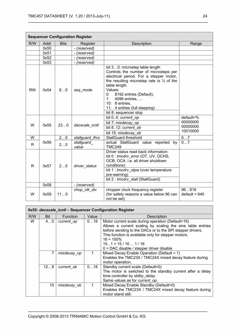
Sequencer Configuration Register
R/W Addr Bits Register Description Range
0x50 - (reserved)
0x51 - (reserved)
0x52 - (reserved)
0x53 - (reserved)
RW 0x54 8…0 seq_mode
bit 3…0: microstep table length Controls the number of microsteps per electrical period. For a stepper motor, the resulting microstep rate is ¼ of the table length. Values: 0: 8192 entries (Default), 1: 4096 entries, … 10: 8 entries, 11: 4 entries (full stepping)
bit 8: sequencer stop
W 0x55 23…0 dacscale_icntl
bit 0..4: current_op default=% 00000000 00000000 10010000
bit 7: mixdecay_op
bit 8..12: current_sb
bit 15: mixdecay_sb
W
0x56
2…0 stallguard_thrs StallGuard threshold 0…7
R 2…0 stallguard_ value
actual StallGuard value reported by TMC249
0…7
R 0x57 2…0 driver_status
Driver status read back information: bit 0 : tmcdrv_error (OT, UV, OCHS, OCB, OCA. i.e. all driver shutdown conditions)
bit 1 : tmcdrv_otpw (over temperature pre-warning)
bit 2 : tmcdrv_stall (StallGuard)
0x58 - (reserved)
W 0x59 11…0 chop_clk_div chopper clock frequency register
(for safety reasons a value below 96 can not be set)
96…818 default = 640
0x55: dacscale_icntl – Sequencer Configuration Register
R/W Bit Function Value Description
W 4…0 current_op 0…16 Motor current scale during operation (Default=16) Allows a current scaling by scaling the sine table entries before sending to the DACs or to the SPI stepper drivers. This function is available only for stepper motors. 16 = 100% 15...1 = 15 / 16 ... 1 / 16 0 = DAC disable / stepper driver disable
7 mixdecay_op 1 Mixed Decay Enable Operation (Default = 1) Enables the TMC23X / TMC24X mixed decay feature during motor operation.
12…8 current_sb 0…16 Standby current scale (Default=0) The motor is switched to the standby current after a delay time controller by stdby_delay. Same values as for current_op.
15 mixdecay_sb 1 Mixed Decay Enable Standby (Default=0) Enables the TMC23X / TMC24X mixed decay feature during motor stand still.
TMC457 DATASHEET (V. 1.20 / 2013-July-11) 25
Copyright © 2008-2013 TRINAMIC Motion Control GmbH & Co. KG
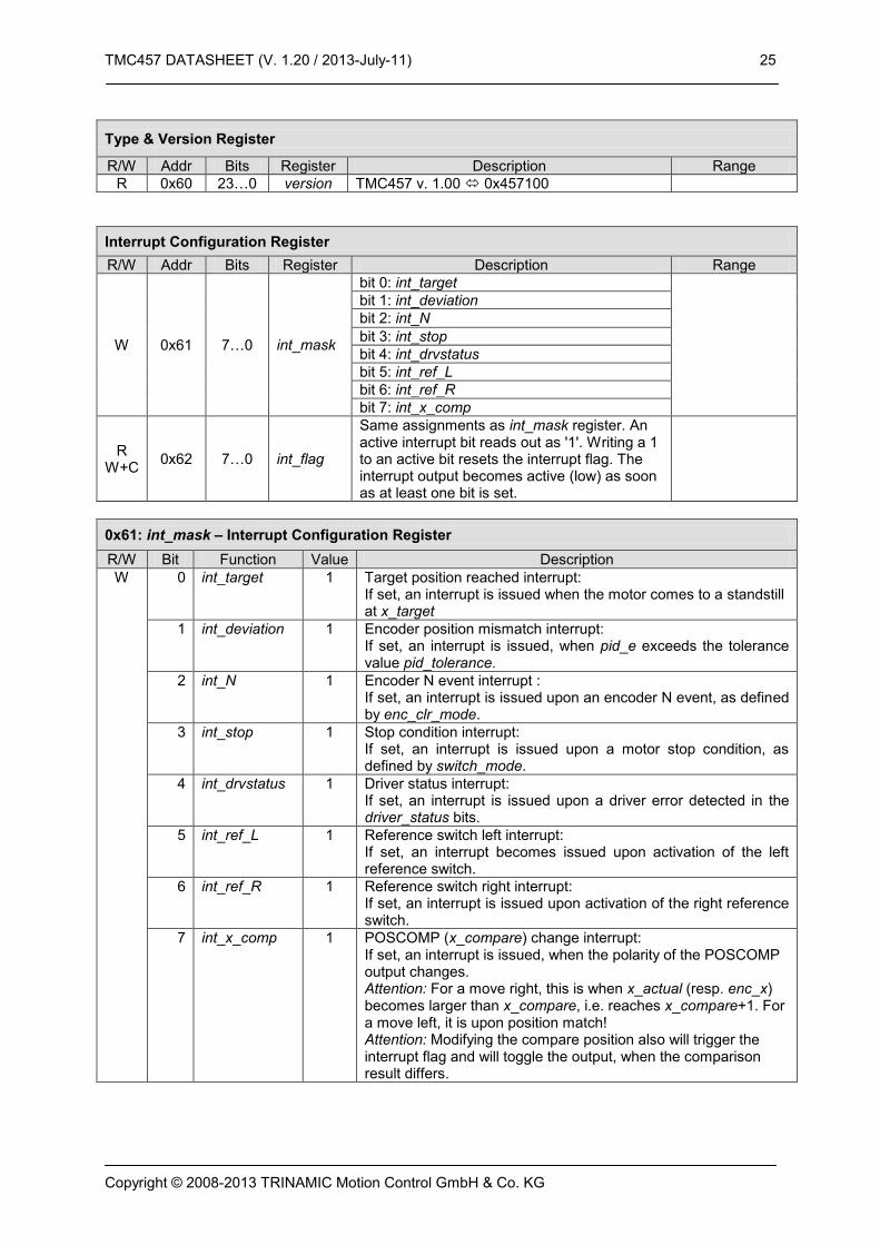
Type & Version Register
R/W Addr Bits Register Description Range
R 0x60 23…0 version TMC457 v. 1.00 0x457100
Interrupt Configuration Register
R/W Addr Bits Register Description Range
W 0x61 7…0 int_mask
bit 0: int_target
bit 1: int_deviation
bit 2: int_N
bit 3: int_stop
bit 4: int_drvstatus
bit 5: int_ref_L
bit 6: int_ref_R
bit 7: int_x_comp
R W+C
0x62 7…0 int_flag
Same assignments as int_mask register. An active interrupt bit reads out as '1'. Writing a 1 to an active bit resets the interrupt flag. The interrupt output becomes active (low) as soon as at least one bit is set.
0x61: int_mask – Interrupt Configuration Register
R/W Bit Function Value Description
W 0 int_target 1 Target position reached interrupt: If set, an interrupt is issued when the motor comes to a standstill at x_target
1 int_deviation 1 Encoder position mismatch interrupt: If set, an interrupt is issued, when pid_e exceeds the tolerance value pid_tolerance.
2 int_N 1 Encoder N event interrupt : If set, an interrupt is issued upon an encoder N event, as defined by enc_clr_mode.
3 int_stop 1 Stop condition interrupt: If set, an interrupt is issued upon a motor stop condition, as defined by switch_mode.
4 int_drvstatus 1 Driver status interrupt: If set, an interrupt is issued upon a driver error detected in the driver_status bits.
5 int_ref_L 1 Reference switch left interrupt: If set, an interrupt becomes issued upon activation of the left reference switch.
6 int_ref_R 1 Reference switch right interrupt: If set, an interrupt is issued upon activation of the right reference switch.
7 int_x_comp 1 POSCOMP (x_compare) change interrupt: If set, an interrupt is issued, when the polarity of the POSCOMP output changes. Attention: For a move right, this is when x_actual (resp. enc_x) becomes larger than x_compare, i.e. reaches x_compare+1. For a move left, it is upon position match! Attention: Modifying the compare position also will trigger the interrupt flag and will toggle the output, when the comparison result differs.

TMC457 DATASHEET (V. 1.20 / 2013-July-11) 26
Copyright © 2008-2013 TRINAMIC Motion Control GmbH & Co. KG
Sine Wave Look-Up Table (LUT) Port Register
R/W Addr Bits Register Description Range
R 0x7F 31…16 15…0
RAM READ (data D of last A)
xxxAAAAAAAAAAAAA xxxxDDDDDDDDDDDD
(data of this address come on next read)
W 0xFF 31…16 15…0
RAM WRITE xxxAAAAAAAAAAAAA
xxxxDDDDDDDDDDDD
6.2.3 Real World Units vs. Units of the TMC457 The units of a TMC457 register content are written as register[457].
Parameter vs. Units
Parameter / Symbol Unit calculation / description / comment
fCLK[Hz] [Hz] clock frequency of the TMC457 in [Hz]
s [s] second
US microstep
FS fullstep
velocity v[Hz] microsteps / s v[Hz] = v[457] * ( 2 * fCLK[Hz] / 2^31 )
acceleration a[Hz/s] microsteps / s^2 a[Hz/s] = a[457] * fCLK[Hz]^2 / (16*256) / 2^30
micro step resolution USR (used U instead of µ for
micro) counts
micro step resolution in number of microsteps (i.e. the number of microsteps between two fullsteps)
v[FS] @ USR US/s v[FS/s] = v[US/2] / USR USR microstep resolution
a[FS/^2] @ USR US/s^2 a[FS/s^2] = a[US/s] / USR
ramp_steps[457] = rs [457] rs = 2 * (v[457])^2 / (a[457]) / 2^18 micro steps during linear acceleration ramp (if v_max is really reached during acceleration)

TMC457 DATASHEET (V. 1.20 / 2013-July-11) 27
Copyright © 2008-2013 TRINAMIC Motion Control GmbH & Co. KG
7 Examples
Following, some examples are given how to program the TMC457 to do a desired task. The examples are given as sequences of SPI datagram as 40 bit hexadecimal number with an additional comment.
$89 12 34 56 78 // set x_target := $12 34 56 78 So, for this example the datagram is $89 12 34 56 78. That datagram sets the register x_target to the hexadecimal value $12345678.
7.1 How to Get a Motor Running // initialize the sine wave look-up table once (either for stepper motor or for piezo motor). for (x=0; x<8192; x++) { y = abs( 4095 * sin(2.0 * 3.141592652 * x / 8192) ); // stepper motor
datagram = ( 0x7F << 32 ) | ( x << 16 ) | ( y ); // compose datagram } This results in a sequence of datagramms for initializing the sine wave look-up table as: $FF $00 $00 $00 $00 // ram[ 0] := 0x0000;
$FF $00 $01 $00 $03 // ram[ 1] := 0x0003;
$FF $00 $02 $00 $06 // ram[ 2] := 0x0006;
.
.
.
$FF $1F $FD $00 $09 // ram[8189] := 0x0009;
$FF $1F $FE $00 $06 // ram[8190] := 0x0006;
$FF $1F $FF $00 $03 // ram[8191] := 0x0003;
// now the motion //
$80 xx xx xx xx // mode := %00 = ramp_mode positioning mode with linear ramps
$83 xx xx xx xx // v_max := $xx xx xx xx
$88 00 00 00 00 // bow_max := 0 = linear ramp
$8F xx xx xx xx // a_max_d_max := $xx xx xx xx
$89 00 BC 61 4E // x_target := 12345678; => move to target position x_target
7.2 Set Incremental Encoder Interface Parameters For this example, we assume to have an incremental encoder with a resolution of 16384 steps per revolution. For the quadrature signals A and B this means that they toggle 8192 tomes per revolution with a phase shift of quarter period. A stepper motor is assumed to have 200 full steps per revolution and is driven with a micro step revolution of 256 micro steps per full step. So, for this example, the stepper motor has 200 * 256 = 51200 micro steps per revolution. The axis of the incremental encoder is assumed to be directly connected to the axis of the stepper motor with a gear. With this, a number of 16384 positions of the incremental encoder are equal to 51200 micro steps of the stepper motor. So, each position count of the encoder is equal to 51200 / 16384 = 3.125 micro steps.

TMC457 DATASHEET (V. 1.20 / 2013-July-11) 28
Copyright © 2008-2013 TRINAMIC Motion Control GmbH & Co. KG
A
B
t
position -4 -3 -2 -1 0 5 64321 7
Figure 6 : Incremental Encoder Signals Outline (AB w/o clear pulse N)
So, the accumulation constant enc_const of the incremental encoder interface of the TMC457 has to be set that each encoder step represents 3.15. This is achieved by setting enc_const = 3.125 * 65536 = 204800 = $00 03 20 00. The datagram sequence doing the initialization of the encoder interface is: $90 00 03 20 00 // set enc_const := $00 03 20 00 $91 00 03 20 00 // set x_enc := $00 00 00 00
$92 00 03 20 00 // set enc_clr_mode := $00 00 00 00, ignore N pulse
8 Notation of Number Systems
Decimal numbers are used as usual without additional identification. Binary numbers are identified by a prefixed % character. Hexadecimal numbers are identified by a prefixed $ character. Alternatively, hexadecimal numbers are identified similar to C language with a prefixed 0x. For better readability of long number spaces are inserted. So, for example the decimal number 42 in the decimal system is written as %101010 in the binary number system, and it is written as $2A or 0x2A in the hexadecimal number system.

TMC457 DATASHEET (V. 1.20 / 2013-July-11) 29
Copyright © 2008-2013 TRINAMIC Motion Control GmbH & Co. KG
9 Pinning, Package, and Electrical data of the TMC457
9.1 Pinning of TMC457 The TMC457-BC is available within a 144 ball fine pitch (1 mm) BGA package.
Important Hints: All pins specified as (n.c. = not connect) must be left unconnected (open). All power supply pins (named V33 for +3.3V and named V15 for +1.5V) and all ground pins must be connected. All inputs and all outputs have 3.3V CMOS level. Level shifters are required when using 5V devices (e.g. micro controller with 5V IO, incremental encoder with 5V ABN outputs, …). Other unnamed pins have to be left open. Pins with comment "do not connect (must not be connected)" must be left open because these are unused but driving outputs.
# BGA
Ball Signal Name In/Out Description / Comment
1 A1 GND ground
2 A2 V33 +3.3V supply voltage
3 A3 - n.c. do not connect (must not be connected)
4 A4 - n.c. do not connect (must not be connected)
5 A5 DIR_IN I direction input
6 A6 GND ground
7 A7 -
8 A8 V15 +1.5V supply voltage
9 A9 - n.c. do not connect (must not be connected)
10 A10 STEP_IN I step input
11 A11
12 A12 GND ground
13 B1 CLK I clock input
14 B2 GND ground
15 B3
16 B4 POSCOMP O position comparator output signal (pls. refer x_compare)
17 B5 ENC_A I A signal from incremental encoder (ABN) for 3.3V level
18 B6
19 B7
20 B8 - n.c. do not connect (must not be connected)
21 B9 - n.c. do not connect (must not be connected)
22 B10
23 B11 GND ground
24 B12 V33 +3.3V supply voltage
25 C1 nEN I clock gating input, logical ored with CLK,
must be connected to ground
26 C2 RES I active high reset input
27 C3
28 C4 V15 +1.5V supply voltage
29 C5 ENC_B B signal from incremental encoder (ABN) for 3.3V level
30 C6
31 C7
32 C8 - n.c. do not connect (must not be connected)

TMC457 DATASHEET (V. 1.20 / 2013-July-11) 30
Copyright © 2008-2013 TRINAMIC Motion Control GmbH & Co. KG
33 C9 - n.c. do not connect (must not be connected)
34 C10 PZO_EN I piezo motor enable (0:stepper motor / 1:piezo motor)
35 C11 SDO_DAC_A O SDO for LTC2602 DAC A input SDI
36 C12 SDO_DAC_B O SDO for LTC2602 DAC B input SDI
37 D1 SCK I SPI clock input from microcontroller
38 D2 nINT o.C./O active low interrupt output (open drain)
39 D3
40 D4
41 D5 ENC_N I N signal from incremental encoder (ABN) for 3.3V level
42 D6
43 D7
44 D8 - n.c. do not connect (must not be connected)
45 D9
46 D10
47 D11
48 D12
49 E1 V15 +1.5V supply voltage
50 E2
51 E3
52 E4 V33 +3.3V supply voltage
53 E5
54 E6 V33 +3.3V supply voltage
55 E7 V33 +3.3V supply voltage
56 E8
57 E9 V33 +3.3V supply voltage
58 E10 V15 +1.5V supply voltage
59 E11
60 E12
61 F1 nSCS I chip select input for microcontroller interface
62 F2 GND ground
63 F3
64 F4 n.c. do not connect (must not be connected)
65 F5 GND ground
66 F6 GND ground
67 F7 GND ground
68 F8
69 F9
70 F10 GND ground
71 F11
72 F12 SCK_DAC O serial clock for LTC2602 DAC
73 G1
74 G2 GND ground
75 G3 n.c. do not connect (must not be connected)
76 G4
77 G5 GND ground
78 G6 GND ground
79 G7 GND ground
80 G8
81 G9
82 G10
83 G11
TMC457 DATASHEET (V. 1.20 / 2013-July-11) 31
Copyright © 2008-2013 TRINAMIC Motion Control GmbH & Co. KG
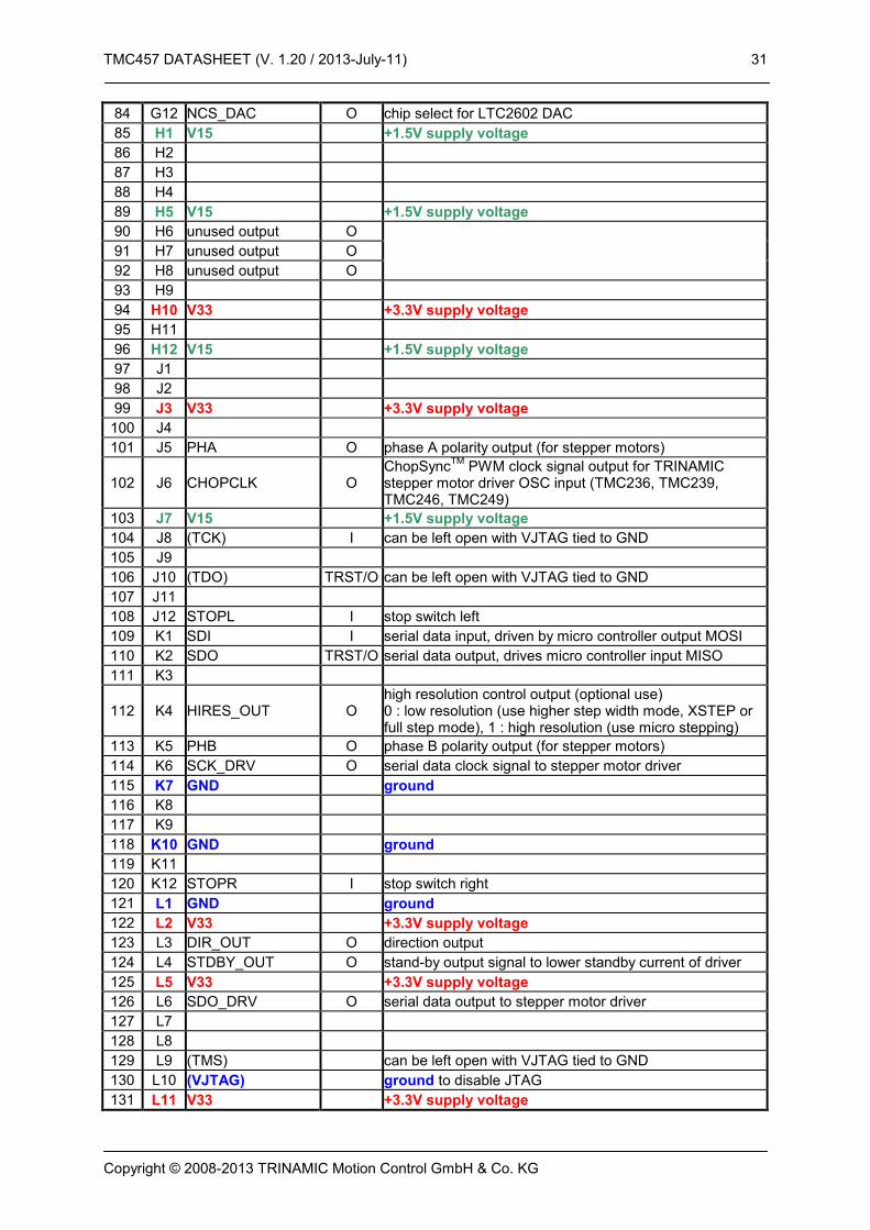
84 G12 NCS_DAC O chip select for LTC2602 DAC
85 H1 V15 +1.5V supply voltage
86 H2
87 H3
88 H4
89 H5 V15 +1.5V supply voltage
90 H6 unused output O
91 H7 unused output O
92 H8 unused output O
93 H9
94 H10 V33 +3.3V supply voltage
95 H11
96 H12 V15 +1.5V supply voltage
97 J1
98 J2
99 J3 V33 +3.3V supply voltage
100 J4
101 J5 PHA O phase A polarity output (for stepper motors)
102 J6 CHOPCLK O ChopSync
TM PWM clock signal output for TRINAMIC
stepper motor driver OSC input (TMC236, TMC239, TMC246, TMC249)
103 J7 V15 +1.5V supply voltage
104 J8 (TCK) I can be left open with VJTAG tied to GND
105 J9
106 J10 (TDO) TRST/O can be left open with VJTAG tied to GND
107 J11
108 J12 STOPL I stop switch left
109 K1 SDI I serial data input, driven by micro controller output MOSI
110 K2 SDO TRST/O serial data output, drives micro controller input MISO
111 K3
112 K4 HIRES_OUT O high resolution control output (optional use) 0 : low resolution (use higher step width mode, XSTEP or full step mode), 1 : high resolution (use micro stepping)
113 K5 PHB O phase B polarity output (for stepper motors)
114 K6 SCK_DRV O serial data clock signal to stepper motor driver
115 K7 GND ground
116 K8
117 K9
118 K10 GND ground
119 K11
120 K12 STOPR I stop switch right
121 L1 GND ground
122 L2 V33 +3.3V supply voltage
123 L3 DIR_OUT O direction output
124 L4 STDBY_OUT O stand-by output signal to lower standby current of driver
125 L5 V33 +3.3V supply voltage
126 L6 SDO_DRV O serial data output to stepper motor driver
127 L7
128 L8
129 L9 (TMS) can be left open with VJTAG tied to GND
130 L10 (VJTAG) ground to disable JTAG
131 L11 V33 +3.3V supply voltage

TMC457 DATASHEET (V. 1.20 / 2013-July-11) 32
Copyright © 2008-2013 TRINAMIC Motion Control GmbH & Co. KG
132 L12 (TRST) I ground to disable JTAG
133 M1 GND ground
134 M2 STEP_OUT O step output
135 M3 XSTEP_OUT O extended step output (lower frequency)
136 M4 nANA_SPI I SPI / not analog input selects type of stepper driver control (0: use external DAC, 1: use TMC236 internal DAC)
137 M5 nCS_DRV O serial data selection signal to stepper driver
138 M6 SDI_DRV I serial data input from stepper driver
139 M7
140 M8
141 M9 (TDI) can be left open with VJTAG tied to GND
142 M10 V33 +3.3V supply voltage
143 M11 PDR I connect this input via 1K pull-down resistor to ground
144 M12 GND ground
Table 2: TMC457-BC Pin Out
9.1.1 Pull-Up / Pull-Down Resistances Some inputs have weak on-chip pull-up resp. weak pull-down resistors. The resistance of these is within the range of 10 kOhm (min.) … 45 kOhm (max.)
9.1.2 Blocking Capacitors Ceramic capacitors of 100nF capacitance should be connected as close as possible at each 1V5 power supply pin and at each 3V3 power supply pin. Alternatively, two power planes – one power plane for +1V5 (V15) and one power plane for +3V3 (V33) can be used.

TMC457 DATASHEET (V. 1.20 / 2013-July-11) 33
Copyright © 2008-2013 TRINAMIC Motion Control GmbH & Co. KG
9.2 Package Outlines and Dimensions 9.2.1 Fine Pitch BGA Package with 144 Balls (FBGA144) of TMC457-BC
A1 ball pad corner
(marked by dot at top side)TOP VIEW
1 2 3 4 5 6 121110987
A
B
C
D
E
F
G
H
J
K
L
M
E/4
D/4
E / E2
D / D2
BOTTOM VIEW
e
12345612 11 10 9 8 7
A
B
C
D
E
F
G
H
J
K
L
M
E1
e
D1 // ccc
SIDE VIEW
b
D1 / E1
A2
aaa
A1c
A bbb
Figure 7 : Package Outline Drawing FBGA144 – (JEDEC MO-192 VAR DAD-1)
Symbol Dimensions in MILLIMETERS Dimensions in INCHES
Min Typ Max Min Typ Max
A 1.35 1.45 1.55
A1 0.35 0.40 0.45
A2 0.65 0.70 0.75
aaa 0.12
b 0.45 0.50 0.55
bbb 0.25
c - 0.35 -
ccc 0.35
D 12.80 13.00 13.20
D1 11.00 BSC
D2 12.80 13.00 13.20
E 12.80 13.00 13.20
E1 11.00 BSC
E2 12.80 13.00 13.20
e 1.00
Table 3 : Dimensions of FBGA144 (Note: BSC = Basis Spacing Between Centers)

TMC457 DATASHEET (V. 1.20 / 2013-July-11) 34
Copyright © 2008-2013 TRINAMIC Motion Control GmbH & Co. KG
10 Micro Controller Interface (SPI)
The communication between micro controller and TMC457 takes place via the four via serial interface, the Serial Peripheral Interface (SPI
TM, SPI is trademark of Motorola). Many types of micro controllers of
different vendors are equipped with SPI hardware.
tSDtSD
CLK
sdi_bit#39
tSCKCL tSCKCHtSUCSC tHDCSC
1 x SDI sampled
one full 40 bit datagram
SDO
SDI
SCK
nSCS
sdi_bit#38 . . . sdi_bit#1
38 x sampled SDI
sdi_bit#0
1 x SDI sampled
tCLK
tDATAGRAMuC
sdo_bit#39 sdo_c_bit#38 ... sdo_c_bit#1 sdo_c_bit#0
tPD
tIS
tSD
tSI
tHDCSC tSUCSC
Figure 8 : Timing Diagram of the Serial Micro Controller Interface
Symbol Parameter Min Typ Max Unit
tSUCSC Setup Clocks for nSCS 3 CLK periods
tHDCSC Hold Clocks for nSCS 3 CLK periods
tSCKCL Serial Clock Low 3 CLK periods
tSCKCH Serial Clock High 3 CLK periods
tSD SDO valid after SCK low 2.5 3.5 CLK periods
tSI SDO valid after nSCS high 4.5 CLK periods
tDAMAGRAMuC Datagram Length 3+3 + 40*6 = 246 CLK periods
tDAMAGRAMuC Datagram Length 12.3 µs
fCLK Clock Frequency 0 20 MHz
tCLK Clock Period tCLK = 1 / fCLK 50 ns
tPD CLK-rising-edge-to-Output Propagation Delay 5 ns
Table 4: Timing Characteristics of the Micro Controller Serial Peripheral Interface (SPI)

TMC457 DATASHEET (V. 1.20 / 2013-July-11) 35
Copyright © 2008-2013 TRINAMIC Motion Control GmbH & Co. KG
11 Characteristics
Symbol Parameter Conditions Min Max Unit
VCORE_AMR core supply voltage -0.3 1.65 V
VOI_AMR IO supply voltage -0.3 3.75 V
VIN_AMR input voltage 3.3V IO supply voltage VIO -0.3 3.6 V
Table 5 - Absolute Maximum Ratings
Symbol Parameter Conditions Min Typ Max Unit
TCOM commercial temperature range 0 70 °C
VCORE nominal core voltage 1.5 V
VIO nominal IO voltage 3.3 V
VIN nominal input voltage 0.0 3.3 V
VINL input voltage low level 85°C (test condition) -0.3 0.8 V
VINH input voltage high level 85°C (test condition) 2.0 3.6 V
VOUTL output voltage low level 85°C (test condition) 0.4 V
VOUTH output voltage high level 85°C (test condition) 2.4 V
IOUTDRV output driver strength 85°C (test condition) 12 mA
Table 6 – DC Ccharacteristics Operating Conditions
Symbol Parameter Conditions Min Typ Max Unit
PDST static power dissipation 25°C 15 mW
PDDY dynamic power dissipation 25°C, 16 MHz 75 mW
PD total power dissipation 25°C, 16 MHz 90 mW
Table 7 - Power Dissipation
Symbol Parameter Conditions Min Typ Max Unit
fCLK Operation Frequency fCLK = 1 / tCLK 20 MHz
tCLK Clock Period Raising Edge to Raising Edge of CLK 50 ns
tCLK_L Clock Time Low 25 ns
tCLK_H Clock Time High 25 ns
tRISE_I Input Signal Rise Time 10% to 90% 5 ns
tFALL_I Input Signal Fall Time 90% to 10% 5 ns
tRISE_O Output Signal Rise Time
10% to 90% 5 ns
tFALL_O Output Signal Fall Time 90% to 10% ns
tSU Setup Time relative to falling clock edge at CLK 5 ns
tHD Hold Time relative to falling clock edge at CLK 5 ns
tPD Propagation Delay Time
50% of rising edge of the clock CLK to 50% of the output
30 ns
Table 8 - General IO Timing Parameters
tCLK_LtCLK_H
tCLK
tSU
tPD
90%
10%
50%
50%
tHDtFALL
tRISE
CLK
OUTPUT
Figure 9 - General IO Timing Parameters

TMC457 DATASHEET (V. 1.20 / 2013-July-11) 36
Copyright © 2008-2013 TRINAMIC Motion Control GmbH & Co. KG
12 Literature
LTC2602 Datasheet, www.linear.com TMC236 Datasheet, www.trinamic.com TMC239 Datasheet, www.trinamic.com TMC246 Datasheet, www.trinamic.com TMC249 Datasheet, www.trinamic.com PiezoMotor, www.piezomotor.se PiezoLEGS® Technology Information, http://www.piezomotor.se/pages/PLtechnology.html PiezoLEGS® Datasheets, http://www.piezomotor.se/pages/PLdownloads.html
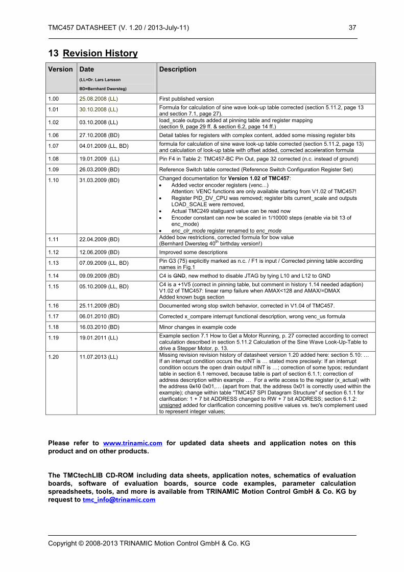
TMC457 DATASHEET (V. 1.20 / 2013-July-11) 37
Copyright © 2008-2013 TRINAMIC Motion Control GmbH & Co. KG
13 Revision History
Version Date
(LL=Dr. Lars Larsson
BD=Bernhard Dwersteg)
Description
1.00 25.08.2008 (LL) First published version
1.01 30.10.2008 (LL) Formula for calculation of sine wave look-up table corrected (section 5.11.2, page 13 and section 7.1, page 27).
1.02 03.10.2008 (LL) load_scale outputs added at pinning table and register mapping (section 9, page 29 ff. & section 6.2, page 14 ff.)
1.06 27.10.2008 (BD) Detail tables for registers with complex content, added some missing register bits
1.07 04.01.2009 (LL, BD) formula for calculation of sine wave look-up table corrected (section 5.11.2, page 13) and calculation of look-up table with offset added, corrected acceleration formula
1.08 19.01.2009 (LL) Pin F4 in Table 2: TMC457-BC Pin Out, page 32 corrected (n.c. instead of ground)
1.09 26.03.2009 (BD) Reference Switch table corrected (Reference Switch Configuration Register Set)
1.10 31.03.2009 (BD) Changed documentation for Version 1.02 of TMC457:
Added vector encoder registers (venc...) Attention: VENC functions are only available starting from V1.02 of TMC457!
Register PID_DV_CPU was removed; register bits current_scale and outputs LOAD_SCALE were removed,
Actual TMC249 stallguard value can be read now
Encoder constant can now be scaled in 1/10000 steps (enable via bit 13 of enc_mode)
enc_clr_mode register renamed to enc_mode
1.11 22.04.2009 (BD) Added bow restrictions, corrected formula for bow value (Bernhard Dwersteg 40
th birthday version!)
1.12 12.06.2009 (BD) Improved some descriptions
1.13 07.09.2009 (LL, BD) Pin G3 (75) explicitly marked as n.c. / F1 is input / Corrected pinning table according names in Fig.1
1.14 09.09.2009 (BD) C4 is GND, new method to disable JTAG by tying L10 and L12 to GND
1.15 05.10.2009 (LL, BD) C4 is a +1V5 (correct in pinning table, but comment in history 1.14 needed adaption) V1.02 of TMC457: linear ramp failure when AMAX<128 and AMAX/=DMAX Added known bugs section
1.16 25.11.2009 (BD) Documented wrong stop switch behavior, corrected in V1.04 of TMC457.
1.17 06.01.2010 (BD) Corrected x_compare interrupt functional description, wrong venc_us formula
1.18 16.03.2010 (BD) Minor changes in example code
1.19 19.01.2011 (LL) Example section 7.1 How to Get a Motor Running, p. 27 corrected according to correct calculation described in section 5.11.2 Calculation of the Sine Wave Look-Up-Table to drive a Stepper Motor, p. 13.
1.20 11.07.2013 (LL) Missing revision revision history of datasheet version 1.20 added here: section 5.10: … If an interrupt condition occurs the nINT is … stated more precisely: If an interrupt condition occurs the open drain output nINT is …; correction of some typos; redundant table in section 6.1 removed, because table is part of section 6.1.1; correction of address description within example … For a write access to the register (x_actual) with the address 0x10 0x01,… (apart from that, the address 0x01 is correctly used within the example); change within table "TMC457 SPI Datagram Structure" of section 6.1.1 for clarification: 1 + 7 bit ADDRESS changed to RW + 7 bit ADDRESS; section 6.1.2: unsigned added for clarification concerning positive values vs. two's complement used to represent integer values;
Please refer to www.trinamic.com for updated data sheets and application notes on this
product and on other products.
The TMCtechLIB CD-ROM including data sheets, application notes, schematics of evaluation
boards, software of evaluation boards, source code examples, parameter calculation
spreadsheets, tools, and more is available from TRINAMIC Motion Control GmbH & Co. KG by
request to [email protected]