Embed Size (px)
Citation preview

International Workshop on Microwave Filters – ESA – CNES - September 2004
TMTM110110--MODE RESONATORS:MODE RESONATORS:Simple ConfigurationsSimple Configurations
For Highly Flexible Waveguide For Highly Flexible Waveguide Filter DesignsFilter Designs
Jens BornemannDepartment of Electrical and Computer Engineering
University of Victoria, Victoria, BCCanada V8W 3P6
Smain AmariDepartment of Electrical and Computer Engineering
Royal Military College, Kingston, ONCanada K7K 7B4
Uwe RosenbergMarconi Communications GmbH
D-71520 Backnang, Germany

OutlineOutline
Motivation
TM110-Mode Resonators
Design Guidelines
Design Results
Non-Resonating Node Model
Design Variations
Conclusions

MotivationMotivation
Find a waveguide filter configuration
which allows the number and locations of transmission zeros to be as flexible as possible,
whose topology is independent of the number and locations of transmission zeros,
which leads to a relatively compact design,
which can be manufactured by standard waveguide fabrication techniques,
which does not require post-assembly tuning.

TMTM110110--Mode Resonators Mode Resonators -- AdvantagesAdvantages
Resonances are based on TM110-mode cavities allowing lower-order modes to generate cross/by-pass coupling.
The maximum number of transmission zeros equals the number of TM110-mode cavities.
The locations of transmission zeros are arbitrary, and simple design guidelines dictate their position with respect to the passband.
Each transmission zero is independently controlled as each resonance is capable of creating its own transmission zero.
The filter topology is in-line and, therefore, ideally suited to fit standard waveguide manufacturing technologies.
Due to the TM110-mode operation, the cavities are short. An N-pole TM110-mode filter usually requires less space than a comparable dual-mode filter based on TE101/011 modes.
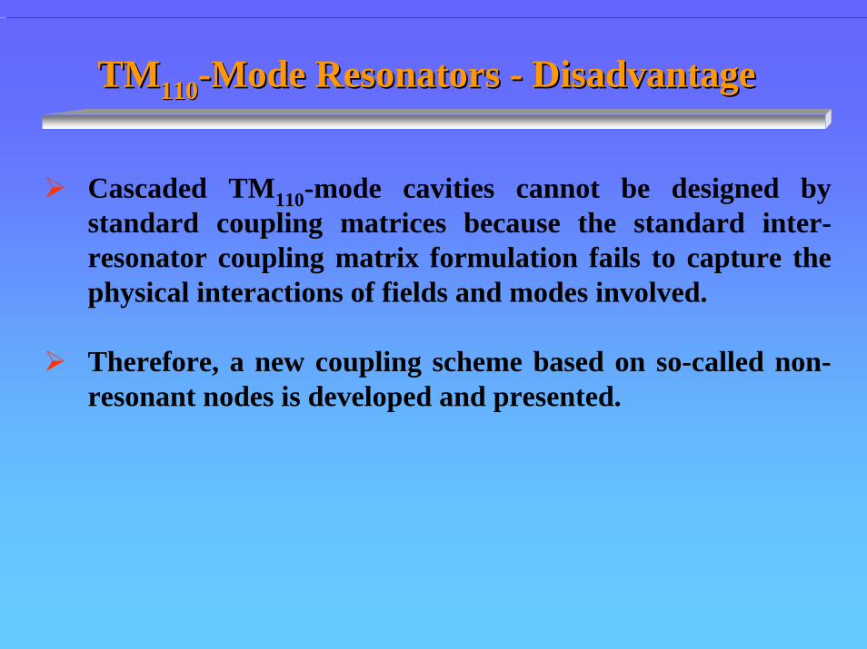
TMTM110110--Mode Resonators Mode Resonators -- DisadvantageDisadvantage
Cascaded TM110-mode cavities cannot be designed by standard coupling matrices because the standard inter-resonator coupling matrix formulation fails to capture the physical interactions of fields and modes involved.
Therefore, a new coupling scheme based on so-called non-resonant nodes is developed and presented.

TMTM110110--Mode ResonatorsMode Resonators
22c
011r
22c
101r
22c
110r
c1
b1
2v
)TE(f
c1
a1
2v
)TE(f
b1
a1
2v
)TM(f
+=
+=
+=
Resonances
Cavity dimensions a, b, c selected such that- TM110 resonates- TE10 , TE01 do NOT resonate
a
b
c
Cavity

TMTM110110--Mode Resonator Mode Resonator ––TheThe SingletSingletCoupling MechanismCoupling Mechanism
Coupling is predominantly magnetic. An incoming TE10mode excites both TE10 and TM11 in the cavity.
TE10Direct and bypass coupling in phase
Transmission zero BELOWBELOW passband
Direct and bypass coupling out of phase
Transmission zero ABOVEABOVE passband
TE10

Design GuidelinesDesign Guidelines – Single Cavity1. Transmission Zero Below Passband
22 24 26 28 30 32 34 36 38 40f/GHz
-40
-30
-20
-10
0
dB
|S11|
|S21|
S L
( )SL 10M TE
( )1 110R TM

2. Transmission Zero Above Passband
22 24 26 28 30 32 34 36 38 40f/GHz
-40
-30
-20
-10
0
dB
|S11|
|S21|
S L
( )SL 10M TE
( )1 110R TM
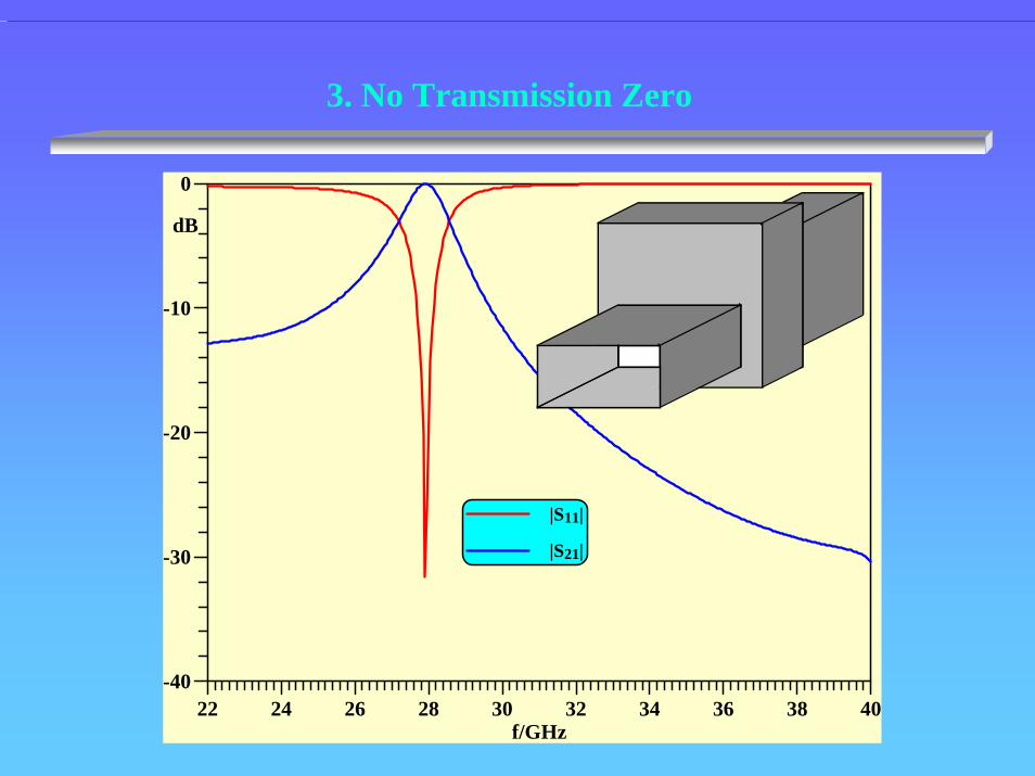
3. No Transmission Zero
22 24 26 28 30 32 34 36 38 40f/GHz
-40
-30
-20
-10
0
dB
|S11|
|S21|

Design GuidelinesDesign Guidelines – Two Cavities1. Two Transmission Zeros Below Passband
22 24 26 28 30 32 34 36 38 40f/GHz
-80
-60
-40
-20
0
dB
|S11|
|S21|

2. Two Transmission Zeros Above Passband
22 24 26 28 30 32 34 36 38 40f/GHz
-80
-60
-40
-20
0
dB|S11|
|S21|

3. Two Transmission Zeros, One Below, One Above Passband
22 24 26 28 30 32 34 36 38 40f/GHz
-80
-60
-40
-20
0
dB |S11|
|S21|
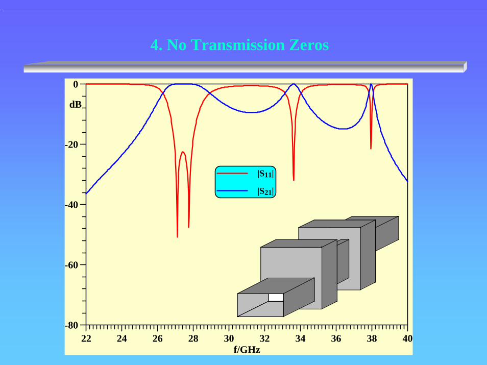
4. No Transmission Zeros
22 24 26 28 30 32 34 36 38 40f/GHz
-80
-60
-40
-20
0
dB
|S11|
|S21|

Design Results Design Results - Filter ExamplesFour-Pole Filter With Chebyshev Response
25 26 27 28 29 30f/GHz-120
-100
-80
-60
-40
-20
0
dBCIET
MMT

Four-Pole Filter With Elliptic-Function-Type Response
25 26 27 28 29 30f/GHz-120
-100
-80
-60
-40
-20
0
dBCIET
MMT
MiCIAN

Four-Pole Filter WithThreeThree Transmission Zeros BelowBelow Passband
23 25 27 29 31f/GHz-140
-120
-100
-80
-60
-40
-20
0
dB
CIET
MMT
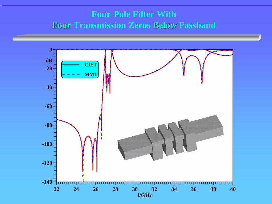
Four-Pole Filter WithFourFour Transmission Zeros BelowBelow Passband
22 24 26 28 30 32 34 36 38 40f/GHz
-140
-120
-100
-80
-60
-40
-20
0
dBCIET
MMT

Four-Pole Filter WithFourFour Transmission Zeros AboveAbove Passband
22 24 26 28 30 32 34 36 38 40f/GHz
-140
-120
-100
-80
-60
-40
-20
0dB
CIET
MMT

MeasurementMeasurement(cutter radius included using (cutter radius included using µµWaveWave Wizard)Wizard)
22 24 26 28 30 32 34 36 38 40f/GHz
-120
-100
-80
-60
-40
-20
0
dB
computed
measured
measured insertion loss less than 0.4dB over 700 MHz bandwidth

Coupling Scheme for Cascaded Coupling Scheme for Cascaded SingletsSinglets
S LSLM
1R
S LSLM
1R
S LSLM
1R
S
1R
L
3R2R
Non-Resonating Nodes (NRN’s)
NonNon--Resonating Node Model (NRNM)Resonating Node Model (NRNM)

Conventional DesignConventional Design[changing a single cross-coupling moves all transmission zeros]
10.0 10.5 11.0 11.5 12.0 12.5 13.0f/GHz
-120
-100
-80
-60
-40
-20
0
dB
S
L +
- ++0.0000 1.3167 0.0000 -0.0303
1.3167 0.0000 1.9272 0.0000M
0.0000 1.9272 0.0000 1.3167-0.0303 0.0000 1.3167 0.0000
⎡ ⎤⎢ ⎥⎢ ⎥=⎢ ⎥⎢ ⎥⎣ ⎦

Design with Singlets[changing a single bypass-coupling moves only one transmission zero]
22 24 26 28 30 32 34 36f/GHz
-100
-80
-60
-40
-20
0
|S11
|, |S
21|
/ dB
Pos 2
Pos 1 unaffected
transmission zero
Pos 1
Pos 2

NonNon--Resonating Node Model (NRNM)Resonating Node Model (NRNM)
1Ω 1Ω
s s jB4
jB1
jB2
jB3 jB5
K12 K23 K34 K45
K13 K35
resonator
LoadSource
non-resonating node
resonator
⎥⎥⎥⎥⎥⎥
⎦
⎤
⎢⎢⎢⎢⎢⎢
⎣
⎡
−−
=
0000.07668.12709.00000.00000.07668.16058.26932.10000.00000.02709.06932.18124.07314.01584.00000.00000.07314.04101.10340.10000.00000.01584.00340.10000.0
M

Design VariationsDesign Variations: Add a Resonant Iris
22 24 26 28 30 32 34 36 38 40f/GHz
-120
-100
-80
-60
-40
-20
0
dB|S11|
|S21|

Three-pole filter: 2 TM110 cavities + resonant iris
-100
-80
-60
-40
-20
0
22 28 34 40Frequency / GHz
s11,
s21
, d
B
—— calculated
—— measured
(cutter radius included (cutter radius included usingusing µµWaveWave Wizard)Wizard)

Seven-pole Quasi-Highpass Filter:3 TM110 cavities + four resonant irises
9 11 13 15 17 19 21f / GHz
-80
-60
-40
-20
0
|S|___dB
|S11| computed
|S21| computed
|S11| measured
|S21| measured
ETH Zürich
ConclusionsConclusions
Cascaded TM110-mode resonators offer an attractive solution for in-line waveguide bandpass filters with arbitrarily located transmission zeros.
These filters have simple geometriessimple geometries, which lend themselves to design by accurate and fast CAD tools, but retain a high flexibilityhigh flexibility as to the number and locations of transmission zeros.
A new coupling matrix approach based on the Non-Resonant Node Model aids in the design of the filters.
Excellent agreement with measured dataagreement with measured data is demonstrated.
TM110-mode resonators are shorter than comparable cavities based on half-wavelength resonances.
Further ReadingFurther Reading
U. Rosenberg, S. Amari and J. Bornemann, “Inline TM110-mode filters with high design flexibility by utilizing bypass couplings of non-resonating TE10/01 modes”, IEEE Trans. Microwave Theory Tech., Vol. 51, pp. 1735-1742, June 2003.
U. Rosenberg, S. Amari and J. Bornemann, “Mixed-resonance compact in-line pseudo-elliptic filters”, in 2003 IEEE MTT-S Int. Microwave Symp. Dig., pp. 479-482, Philadelphia, USA, June 2003.
S. Amari, U. Rosenberg and J. Bornemann, “Singlets, cascaded singlets and the non-resonating node model for advanced modular design of elliptic filters”, IEEE Microwave Wireless Component Lett., Vol. 14, pp. 237-239, May 2004.
S. Amari, U. Rosenberg and J. Bornemann, “A novel approach to dual and triple-mode pseudo-elliptic filter design”, in 34th European Microwave Conf., Amsterdam, The Netherlands, Oct. 2004.
U. Rosenberg, S. Amari, J. Bornemann and R. Vahldieck, “Compact pseudo-highpass filters formed cavity and iris resonators”, in 34th European Microwave Conf., Amsterdam, The Netherlands, Oct. 2004.