Embed Size (px)
Citation preview

TM
RPM SeriesTM Rotary Meter(Standard, ETC & CMTC)
Installation, Operation, Maintenance
Line Mounted Models
3.5M Standard Meter Shown
IM 5700.4

AMERICAN METER 5 YEAR LIMITED WARRANTY
RPM SERIES ROTARY METERS
American Meter Co. Industrial Products Division (hereafter referred to as the Company) offers to supply RotaryMeters of exceptional design, material and workmanship. The company will correct any defect(s) in material orworkmanship occurring during the period of one year after shipment (the “Warranty Start Date”) providing thePurchaser has given the company immediate written notice of the defects.
In addition an extended 5-year warranty to the original owner in a permanent meter installation is offered againststructural failure and for other identified components (list furnished by writing our general offices) from the WarrantyStart Date under normal use, operation and maintenance.
The Company obligation under this warranty is limited at its option to repayment of the purchase price, repair,replacement, or furnishing a similar part upon inspection and confirmation of the defective condition.
THERE ARE NO OTHER WARRANTIES, EITHER EXPRESSED OR IMPLIED AND ANY OTHER WARRANTIESARE HEREBY EXPRESSLY DISCLAIMED.
No allowance or reimbursements will be made for repairs or alterations unless made with the written consent firstobtained from the Company.
In no event shall the Company liability to the customer, regardless of the reason, exceed the purchase price ofthe product. No claim of breach of warranty shall constitute a cause for cancellation of this contract or any partthereof.
The Company reserves the right to exclude from this warranty damages caused by any of the following:
• Overpressurization beyond the badge rating of the meter.
• Snap acting loads.
• Work done, apparatus furnished, repairs or alterations made by others.
• Auxiliary equipment supplied not manufactured by the Company
• Less than specification performance caused by improper gas stream filtration, and improper installation.
• Collision, fire, theft, lightning, vandalism, explosion, natural disaster, or objects striking the meter.
• Misuse of the meter for applications and processes not originally designed for or recommended by the company.
• Corrosion due to improper environmental conditions, chemical treatments, after-market products and chemicalreactions.
• Sealants applied as excessive or not recommended by the company.
Laws of the Commonwealth of Pennsylvania are applicable to this warranty.
CAUTION“As a knowledgeable user of American Meter’s products, we are sure that you are aware that parts in the Company’smeters and regulators contain or are coated with heavy metals such as cadmium, zinc, lead and chromium.Obviously, therefore, repair or refurbishment of this equipment should take into account the presence of thesematerials and should comply with all state and federal requirements concerning worker protection, proper disposaland safety, including protection against exposure to dust and fumes.”

TABLE OF CONTENTS
Chapter 1 Introduction
General Description ............................................................................................................................. 1-1
Features ............................................................................................................................................... 1-2
Standards ............................................................................................................................................. 1-3
Principles of Operation ......................................................................................................................... 1-4
Sizing/Accuracy ................................................................................................................................... 1-5
Chapter 2 Installation
Basic Requirements ............................................................................................................................. 2-1
Uncrating the Meter .............................................................................................................................. 2-3
Mounting and Leveling .......................................................................................................................... 2-4
Check & Start-up Operation ................................................................................................................. 2-4
Lubrication ............................................................................................................................................ 2-5
Differential Testing................................................................................................................................ 2-7
Chapter 3 Optional Temperature Compensator
Why Temperature Correction? ............................................................................................................. 3-1
Standard General Description .............................................................................................................. 3-1
CMTC General Description .................................................................................................................. 3-2
Vertical & Horizontal Installation ........................................................................................................... 3-3
CMTC Operation .................................................................................................................................. 3-4
Reverse Flow Conversion ................................................................................................................... 3-5
Proving Operations .............................................................................................................................. 3-7
Meter Shop Test Procedures ............................................................................................................. 3-10
Chapter 4 Inspection/Routine Maintenance
Maintenance ......................................................................................................................................... 4-1
Troubleshooting .................................................................................................................................... 4-2
Chapter 5 Optional Instrument Drive
Instrument Drive Kit .............................................................................................................................. 5-1
Optional Mercury ID ............................................................................................................................. 5-2
Chapter 6 Appendix
Maintenance Record Form ................................................................................................................... 6-1
Differential Rate Data Test Form.......................................................................................................... 6-2

WARNING - EXPLOSION HAZARD
Read carefully and follow all instructions shippedwith this meter. The incorrect installation of thisequipment could result in escaping gas, and pose apotential explosion hazard.
! !

1-1
Meters utilized in the natural gas industry are divided into twogeneral categories: inferential or positive displacement.
The inferential category includes turbine and orifice meters.Turbines are also referred to as velocity meters as they mea-sure the gas velocity flowing through a pipeline.
Meters in the positive displacement category are the dia-phragm and rotary types.
Rotary gas meters have been utilized in the industrial andcommercial markets for decades and were produced in vari-ous designs. For today’s gas utility, the rotary’s primary appli-cation is to fill the flow gap between the diaphragm meter andthe turbine meter. Like the diaphragm meter, the rotary metermeasures gas with compartments that alternately fill andempty.
In addition to non-residential applications, many productionfields or well head users utilize the rotary meter to provideaccurate well head measurement at various pressures. Whenproperly sized, installed, and maintained, the rotary meterprovides accurate and dependable measurement from low tohigh pressure applications for many years.
GENERAL DESCRIPTION
The rotary meter is suitable for measuring most types of cleancommon gases. It is NOT intended for handling liquids, acety-lene or sewage gas, and its operation/accuracy can be af-fected by excessive deposits of dirt or other foreign materialscarried in the gas stream.
The basic type of rotary meter utilizes two opposite rotatingtwo-lobe impellers. Internally there are no contacting parts inthe measurement chamber. As adjusted from the factory, thereis usually no wear as long as the meter is kept clean, leveled,and the bearings are properly lubricated.
FEATURES
American Meter’s RPM Series Rotary Meters are available inten (cfh) capacities @ 175 psig (12 bar) MAOP:
• 8.0C • 3.5M (G65)• 9 .0C (G16) • 5.5M (G100)• 1.1C • 7M• 1.5M (G25) • 11M• 2M (G40) • 16M (G250)
Introduction

1-2
The meters are available in three configurations:
• Standard• Temperature Compensated (optional) Electronic & Mechani-
cal. See page 3-1 and 3-2 for details.• Instrument Drive (optional)
All rotary meters are equipped with an uncorrected mechanicalcounter.
The output end with uncorrected mechanical counter rotates90o without interrupting pressurized chamber to facilitatevertical or horizontal mounting.
All models/sizes can be easily converted to instrument drive.The universal mounting plate rotates 360o in 45o increments.
Performance characteristics:
• Pressure rating: 175 psig (12 bar) Optional: 200psig (14bar) or 285 psig (20 bar)
• Proof accuracy: +1% (U.S. and Canada) + 2% (Int’l) at lowflow rates.
• Rangeability (see Rangeability Chart). ref.: ANSI B109.3Rotary Gas Meters; Part III; page 10, Accuracy.
• Operating temperature: -40o to 140oF (-40o to 60oC)
• Temperature compensation display: -40o to 140oF (-40o to60oC)
• Output of 8.0C to 11M is 10 cubic feet per pulse or .1 cubicmeter per pulse. 7M & 16M is 1 cubic meter. 16M is 100cubic feet per pulse.
An optional Electronic Temperature Compensator is alsoprovided. See page 3-1 for details.Fig. 1-1 Compensating Module
Rangeability ChartNote: The numbers listed represent fully assembled production meters using standard proving practice.
Cubic Ft/Hr RangeabilityModel Start Rate +1% +2%
8.0C/9.0C <3.0 >30:1 >60:1
1.1C/1.5M <3.0 >40:1 >75:1
2M/3.5M <4.0 >75:1 >140:1
5.5M <4.4 >120:1 >210:1
7M <5.5 >70:1 >115:1
11M <5.5 >120:1 >225:1
16M <7.0 >100:1 >150:1
Introduction
NON - COMPENSATED VOLUME
READING X 100 = CU FT3
0 0 0 0 0 0 0
MINI-MAX
Electronic Gas Volume Corrector
CFx100mi

1-3
STANDARDS
The American Meter’s RPM Series Rotary Meter meets thefollowing codes and standards:
• ASME Boiler & Pressure Vessel Code; Section VIII
• ANSI B16.5 Flanged Pipe & Fittings
• ANSI B31.8 Gas Piping
• ANSI B109.3 Rotary Gas Meters (92)
• 49 CFR 192 Min. Federal Safety Standards
• National Safe Transit Association (NSTA-1A-Packaging)
• Underwriter’s Laboratory (UL)
• Measurement Canada
PRINCIPLES OF OPERATION
The opposite rotating “figure 8” impellers of a rotary meteroperate within a rigid casing that has inlet and outlet gasconnections on opposite sides.
The impellers rotate as a result of the pressure drop across themeter as downstream gas is consumed. The rotating impellersseparate the flowing gas stream into small segments beforethe gas enters the downstream piping. These small segmentsare counted using a gear train which drives the meter index orcorrecting instrument. See Fig. 1-2.
Position 1 As the bottom impeller rotates in a counter-clockwise direction toward the horizontal posi-tion, gas enters the space between the impellerand the cylinder.
Position 2 At the horizontal position, a definite volume ofgas is contained in the bottom compartment.
Position 3 As the impeller continues to turn, the volume ofgas is then discharged.
Position 4 Concurrently, the top impeller rotating in theopposite direction has closed to its horizontalposition, confining another known and equalvolume of gas.
This process is repeated four times for each complete revolu-tion of the impeller shafts.
Introduction
Fig. 1-2 Rotation of Impeller Shaft
FLOW
FLOW
FLOW
FLOW
Position 2
Position 1
Position 4
Position 3

1-4
SIZING/ACCURACY
There are four considerations to take into account whenselecting and sizing a meter:
1. Inlet pressure
2. Required flow
3. Type of customer
4. Required pressure
Additionally, when selecting a rotary meter for a specificinstallation, the normal minimum and maximum allowableoperating pressure (MAOP) should always be considered.
Industry standards recommend sizing rotary meters for 60% ofthe rated capacity and not lower than 10% of capacity. Be-cause of the “no contacting parts” design, some gas can seepthrough the meter creating an error at low meter speeds.
AMERICAN METER CO. recommends that the meter be sizedso it will NOT OPERATE below 10% of its rated capacity forlong periods of time. Low flow rate error is corrected eachtime the rotary meter operates at 10% or more of its ratedcapacity. Above the 10% flow rate, the meter’s accuracy isslightly greater than 100%, and this compensates for possibleerror at low flow or pilot load flow rates.
EXAMPLE:
The following example depicts an “average day in accuracy ”measurement from a rotary meter:
A 5.5M rotary meter measuring natural gas consumption at abakery that operates 16 hours a day:
Gas Consumption Meter Accuracy16 hrs x 4000 CFH = 64000 x 100.5% = 64320
+ 8 hrs x 300 CFH (low flow) = 2400 x 98.0% = 2352
24 hrs = 66400 vs. 66672(actual) (registered)
66672 — 66400 Average Daily Accuracy = 100.4%
Introduction

2-1
Installation
BASIC REQUIREMENTSWhen installing a rotary meter, it can be easy to overlookdetails that may hinder meter performance and maintenance.Usual emphasis is put on a clean gas flow through the meterby use of filtration and proper inlet and outlet piping. There aresome DO'S AND DON’TS that should always be consideredwhen designing a rotary meter set.
• Refrain from using excessive amounts of pipe dope oninlet piping to the rotary meter. Chunks of pipe dopecan break loose from screwed fittings and fall onto andin-between impeller lobes, rendering the meter immedi-ately inoperative.
• Check for excess dirt, scale and weld splatters in thepipeline.
• Install an in-line pipe screen filter upstream from themeter to keep debris (i.e., stones, tap shavings, scale,and weld beads) from entering and causing damage tothe meter.
The use of an AMCO 80 mesh strainer is stronglyrecommended. See the parts list in the back of thisdocument (Page 5.6) for ordering information. Theelimination of smaller contaminants (i.e., grit) can beachieved with an AMCO KleanlineTM micron filter.
• If selecting full-port valves for the inlet and outlet piping,always use ball valves that require no, or minimallubrication to achieve tight shut-off. Excessivelygreased plug valves will degrade rotary meter perfor-mance due to lubricant seeping into the meter.
• AMCO recommends if possible, installing a straight runof pipe without restrictions (i.e., valves, regulators, etc.)for a distance of six pipe diameters on either side of themeter (Fig. 2-1). This optimum set design will prevent areduction in meter accuracy resulting from a turbulentgas stream.

2-2
Installation
• Bypass piping can effectively reduce time spent ondifferential testing and maintenance. If a combinedmeasurement and regulation set is installed, metertesting and regulation inspection can all be completedat the same time with minimum disruption of service.
Bypass valves should have a tamper proof lock or sealto prevent theft of gas.
• Adequate service (working) clearance around themeter should be maintained to allow easy access forreading the meter indexes. For temperature compen-sated meters, a 6" clearance space for the temperatureprobe is necessary to permit the removal of the TCcounter module if necessary. Clearances are alsorequired for differential testing access, inspection andnormal lubrication maintenance.
• The meter should never be installed so that it is lowerthan the discharge pipe runs. This would allow themeter to become a sump for condensate and otherforeign material.
Fig. 2-1 Typical Installation (not to scale)

2-3
Installation
UNCRATING THE METERUnpacking instructions are also included in the shippingcontainer.
American RPM Series meters utilize packaging that meet ISTA(International Safe Transit Association) test specifications.Even with the packaging’s rugged construction, the metershould be handled with care in transport and storage to protectits factory certified accuracy.
NOTE: If outer package shows evidence of damage throughmishandling in transit, NOTIFY the shipper and immediatelyperform a careful inspection of the meter. FILE a claim with theshipper if damage is indicated and also notify your local AMCOsales office. See Appendix for listing.
NOTE: All packaging has size of meter inside, and an arrowdepicting UP.
1. Carefully open the shipping container at the top seam.When cutting the top seam be careful not to cut too deeplyinto the area where the meter and accessories are lodged.
2. Open up the two top flaps and bend outward.
3. Remove the lubrication kit, instruction manual, and mag-netic wand if the meter is equipped with the temperaturecompensator. The box will also contain the certificate ofaccuracy documentation. This should be filed for furtherreference.
4. Remove the center and end cardboard dividers.
5. Carefully grasp the meter by the center of the body and liftupward. See Figure 2-2.
CAUTION: If the meter is equipped with a temperaturecompensator module, DO NOT LIFT THE METER BYTHE COMPENSATOR MODULE ON THE END.
6. Always check new meters for free rotation after removalfrom the shipping container. This procedure is described inthe following section, Check and Start-up.
7. If the meter is not to be installed or tested immediately,return the meter to its shipping container and place horizon-tally, red arrow pointing UP, in a dry, protected area. DONOT put oil in the meter until it is to be installed.
Fig. 2-2 Unpacking the Meter

2-4
Installation
MOUNTING AND LEVELING• Proper support is necessary for any gas meter installation.
If properly designed it provides stability and a sound baseto eliminate vibration to the meter. If the ground surface isunstable, industry standards recommend an 8"x 8"x16"solid block be used to set the inlet and outlet risers. Riserlegs should be at 90o angles from the set.
• A rotary meter can be installed horizontally facilitating thechange out of an old meter set; however the preferredinstallation is top inlet in a vertical pipeline. Vertical mount-ing allows contaminants to be expelled more easily viagravity from the meter.
• A rotary meter should be installed close to 100% level at alltimes. Deviation from level should not be more than+1/16" per foot in all directional planes. If the meter is notset level, it is possible to overfill or underfill the oil reser-voirs while the oil sight glasses indicate the proper level.Overfilling with oil can cause the meter to read incorrectlydue to increased drag on the gears and possible bleedingof oil into the measurement chamber. Under filling metersthat are not level can lead to excessive bearing wear andwill be evident on differential testing.
CHECK & START-UP OPERATIONThe following steps should be utilized to insure a trouble-freestart-up of the AMCO RPM Series Rotary Meters.
1. Remove the meter from the shipping carton and inspect fordamage that may have occurred during transit. See previ-ous section, Uncrating the Meter procedure.
2. Set the meter on the bottom of the over-turned shippingcarton and remove the protective caps from both flangeopenings.
CAUTION: Do not let dirt, debris, etc., enter flangeopenings!
3. Lightly blow into the inlet of the meter. This slight air pres-sure should cause the impellers to rotate freely and cometo a stop slowly. If the impellers do not turn, this indicates apossible foreign object within the measurement cavity andthe meter should be returned to the repair shop or manu-facturer.
4. Verify that the mating flanges or optional flanges (refer toFigure 2-3), for the meter plus the correct distance (FL) areas close to level; within 1/16" per foot in all directions.
Fig. 2-3 Optional 11/2" NPT Flange(9.0 C & 1.5M Only)
P/N 52996K001
NON - COMPENSATED VOLUME
READING X 100 = CU FT3
0 0 0 0 0 0 0
ADD O
H E
I
R E
L
2-5
Installation
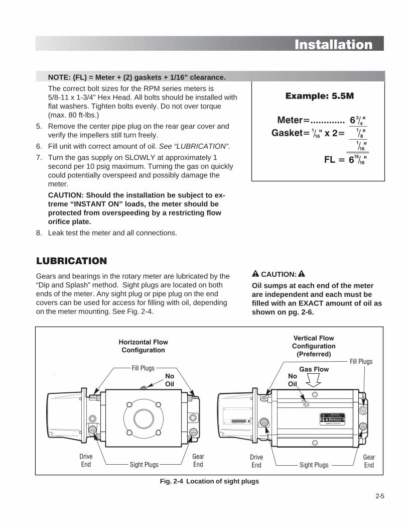
NOTE: (FL) = Meter + (2) gaskets + 1/16" clearance.
The correct bolt sizes for the RPM series meters is5/8-11 x 1-3/4" Hex Head. All bolts should be installed withflat washers. Tighten bolts evenly. Do not over torque(max. 80 ft-lbs.)
5. Remove the center pipe plug on the rear gear cover andverify the impellers still turn freely.
6. Fill unit with correct amount of oil. See “LUBRICATION”.
7. Turn the gas supply on SLOWLY at approximately 1second per 10 psig maximum. Turning the gas on quicklycould potentially overspeed and possibly damage themeter.
CAUTION: Should the installation be subject to ex-treme “INSTANT ON” loads, the meter should beprotected from overspeeding by a restricting floworifice plate.
8. Leak test the meter and all connections.
LUBRICATIONGears and bearings in the rotary meter are lubricated by the“Dip and Splash” method. Sight plugs are located on bothends of the meter. Any sight plug or pipe plug on the endcovers can be used for access for filling with oil, dependingon the meter mounting. See Fig. 2-4.
Fig. 2-4 Location of sight plugs
CAUTION:
Oil sumps at each end of the meterare independent and each must befilled with an EXACT amount of oil asshown on pg. 2-6.
2-6
Installation
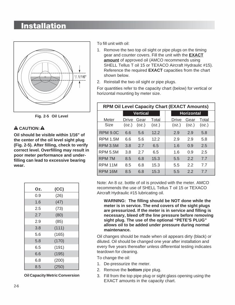
Fig. 2-5 Oil Level
Oz. (CC)
0.9 (26)
1.6 (47)
2.5 (73)
2.7 (80)
2.9 (85)
3.8 (111)
5.6 (165)
5.8 (170)
6.5 (191)
6.6 (195)
6.8 (200)
8.5 (250)
Oil Capacity Metric Conversion
CAUTION:
Oil should be visible within 1/16" ofthe center of the oil level sight plug(Fig. 2-5). After filling, check to verifycorrect level. Overfilling may result inpoor meter performance and under-filling can lead to excessive bearingwear.
To fill unit with oil:
1. Remove the two top oil sight or pipe plugs on the timinggear and counter covers. Fill the unit with the EXACTamount of approved oil (AMCO recommends usingSHELL Tellus T oil 15 or TEXACO Aircraft Hydraulic #15).Reference the required EXACT capacities from the chartshown below.
2. Reinstall the two oil sight or pipe plugs.
For quantities refer to the capacity chart (below) for vertical orhorizontal mounting by meter size.
RPM Oil Level Capacity Chart (EXACT Amounts)Vertical Horizontal
Meter Drive Gear Total Drive Gear TotalSize (oz.) (oz.) (oz.) (oz.) (oz.) (oz.)
RPM 9.0C 6.6 5.6 12.2 2.9 2.9 5.8
RPM 1.5M 6.6 5.6 12.2 2.9 2.9 5.8
RPM 3.5M 3.8 2.7 6.5 1.6 0.9 2.5
RPM 5.5M 3.8 2.7 6.5 1.6 0.9 2.5
RPM 7M 8.5 6.8 15.3 5.5 2.2 7.7
RPM 11M 8.5 6.8 15.3 5.5 2.2 7.7
RPM 16M 8.5 6.8 15.3 5.5 2.2 7.7
Note: An 8 oz. bottle of oil is provided with the meter. AMCOrecommends the use of SHELL Tellus T oil 15 or TEXACOAircraft Hydraulic #15 lubricating oil.
WARNING: The filling should be NOT done while themeter is in service. The end covers of the sight plugsare pressurized. If the meter is in service and filling isnecessary, bleed off the line pressure before removingsight plug. The use of the optional “PETE’S PLUG”allows oil to be added under pressure during normalmaintenance.
Oil changes should be made when oil appears dirty (black) ordiluted. Oil should be changed one year after installation andevery five years thereafter unless differential testing indicatesteardown for cleaning.
To change the oil:1. De-pressurize the meter.2. Remove the bottom pipe plug.3. Fill from the top pipe plug or sight glass opening using the
EXACT amounts in the capacity chart.

2-7
Installation
DIFFERENTIAL TESTING:Meter accuracy, regardless of the manufacturer, is unlikely toimprove with use. Therefore it is important to develop perfor-mance standards on the meter at installation so those stan-dards can be monitored at a future point in time.
Differential testing is used to determine changes in the meterafter installation. The test is performed using a differentialpressure manometer under actual conditions of gas flow rate,line pressure and specific gravity. In lieu of a transfer prover,differential testing gives a good indication of the operationalcondition of the meter. It does not indicate meter accuracy.
AMERICAN METER CO. furnishes a test report with eachrotary meter enclosed in the shipping carton. The test reportindicates percent rated capacity, accuracy, proof and differen-tial pressure for various flow rates of the meter. This test reportalso is kept on file by AMCO for the life of the meter.
The Appendix of this manual includes a blank chart. Theinstaller can record a performance curve on initial start-up ofthe meter. The installer should plot a point on the chart for eachdifferential at each level of capacity tested. Three points arerequired within the 25% to 100% range to establish a represen-tative curve at installation, after 5/10 years and after solventflushing. Refer to Fig. 2-6.
Field testing on gas below 15 psig can be compared directlywith AMCO factory test results on air as indicated on thefurnished accuracy test report. It is always important to test themeter under the actual conditions of gas line pressure and
Fig. 2-6 Plot of Differential Testing
3.0
2.0
1.0
00 10 50
Percent of Maximum Flow Rate
Flow Rate at Inlet Conditions
Installation Year 5 Year 10 Year 10 (after flushing)
Diffe
rent
ial I
nche
s W
.C.
30 70 9020 6040 80 100
Differential PressureTesting Taps
ADD O
H E
I
R E
L

2-8
Installation
DIFFERENTIAL TESTING: CON’T.
specific gravity that will exist in service. This is particularlyimportant when line pressure is above 15 psig so that a directcomparison with later tests can be made. Although as previ-ously stated, accuracy cannot be directly determined bydifferential test.
Test results have indicated that an increase of up to 50% indifferential pressure can be tolerated without affecting meteraccuracy at flow rates of 25% and above.
There are three things that can potentially affect a meter’saccuracy which would also affect the differential test results:
1. Change in the “Static Displacement”
2. Enlargement of clearances between moving parts
3. Internal resistance increase
Change in the “Static Displacement”
The U.S. National Bureau Of Standards Paper 1741, “TEST-ING LARGE CAPACITY GAS METERS,” pg. 187, states:
“The Static Displacement of a Rotary gas meterappears to be almost unaffected by deposits,even those resulting from unpurified gas.Hence, having once been determined, it willseldom be necessary to redetermine.”
Enlargement of clearances between moving parts
There is NO wearing of internal parts because the movingparts have NO direct contact with other surfaces. Henceclearances DO NOT change between the body and the impel-lers.
Internal resistance increase
Internal resistance is the most critical factor in the effects onmeter accuracy because any significant increase in resistancewill increase the pressure drop across the meter.
The most common causes of an increase in internal resistanceare: dirt, pipe dope, thread shavings between impellers, wornbearings bending torque on the body, and heavyweight orexcessive amounts of oil.
If the differential test at the time of installation is found to be50% greater than what was indicated on the AMCO factorytest results, the meter should be taken out of service and

2-9
Installation
DIFFERENTIAL TESTING: CON’T.
returned to your local AMCO sales representative for replace-ment under the terms of the WARRANTY described previ-ously.
If the differential test during normal maintenance and afterprolonged service is found to be more than 50%, the metershould be taken out of service for cleaning.
A simple flushing with mineral spirits, kerosene or your compa-ny approved solvent should easily remove the foreign materi-als within, and bring the meter back into acceptable specifica-tion.
If the flushing operation fails to bring the meter into specifica-tion, the unit should be returned to your approved meter repairshop for tear down and bearing replacement. AMCO recom-mends draining the oil from the meter end caps after blowdownto atmosphere, to prevent oil from splashing onto the impellersduring transport.
While there is no nationally established time period for testing,some states have formally adopted differential rate test peri-ods. Aside from these states, a five year test interval is gener-ally considered acceptable.
Recommended frequency of differential testing:
1. At the time of installation
2. Twelve months after initial installation
3. Every 5 years thereafter
NOTE: Always consult your company policy or state/countrycommissions for specific time intervals on differential rate testperiods.
See sample Differential Test Chart on page 2-10.
See Maximum Allowable Differential Pressure Charts at psig.by meter size on pages 2-10, 2-11 & 2-12.

2-10
Installation
Sample Differential Rate Test Data
Meter Model 5.5M Mfg. Serial No. 975342 Utility Serial No. Location Date Installed 1/1/97 Register Reading
Line Gas Sp. Volume Run Rate Diff. PressurePress. Temp Grav. Measured TIme CFH Ins. W.C. % Chg. Date
Initial Test - New Meter
2 psig 60oF .6 10 cf 29s 1250 .1 - 1/1/972 psig 60oF .6 10 cf 14s 2500 .3 - 1/1/972 psig 60oF .6 10 cf 8s 4750 1.3 - 1/1/97
Periodic Check Tests
2 psig 60oF .6 10 cf 29s 1250 .14 40 3/17/002 psig 60oF .6 10 cf 14s 2500 .4 33 3/17/002 psig 60oF .6 10 cf 8s 4750 1.5 15 3/17/002 psig 60oF .6 10 cf 29s 1250 .2 100 3/25/052 psig 60oF .6 10 cf 14s 2500 .7 133 3/25/052 psig 60oF .6 10 cf 8s 4750 2.2 69 3/25/052 psig 60oF .6 10 cf 29s 1250 .12 20 3/26/052 psig 60oF .6 10 cf 14s 2500 .35 17 3/26/052 psig 60oF .6 10 cf 8s 4750 1.4 8 3/26/05
AMCO 8.0C/9.0C Rotary Meter - Maximum Allowable Differential Pressure
Percent Flowrate ATM Volume Run Rate Diff. PressureCapacity (CFH) ATM 15 psig 30 psig 45 psig 60 psig 90 psig
5 45 0.015 0.015 0.015 0.015 0.015 0.015
10 90 0.03 0.03 0.03 0.03 0.03 0.03
20 180 0.045 0.06 0.045 0.06 0.06 0.09
30 270 0.06 0.09 0.075 0.09 0.12 0.135
40 360 0.09 0.105 0.135 0.15 0.18 0.24
50 450 0.12 0.12 0.165 0.165 0.225 0.3
60 540 0.15 0.18 0.21 0.225 0.255 0.33
70 630 0.21 0.27 0.3 0.315 0.375 0.45
80 720 0.27 0.315 0.42 0.45 0.525 0.63
90 810 0.315 0.345 0.465 0.57 0.645 0.81
100 900 0.36 0.375 0.54 0.66 0.795 1.08
110 990 0.405 0.42 0.63 0.78 0.69 1.125
120 1080 0.465 0.495 0.645 0.795 0.975 1.335

2-11
Installation
AMCO 11C/1.5M Rotary Meter - Maximum Allowable Differential Pressure
Percent Flowrate ATM Volume Run Rate Diff. PressureCapacity (CFH) ATM 15 psig 30psig 45 psig 60 psig 90 psig
5 75 0.015 0.045 0.045 0.045 0.06 0.06
10 150 0.015 0.06 0.06 0.075 0.09 0.105
20 300 0.03 0.09 0.105 0.12 0.15 0.165
30 450 0.06 0.12 0.255 0.27 0.3 0.42
40 600 0.09 0.18 0.21 0.21 0.225 0.33
50 750 0.12 0.255 0.27 0.27 0.3 0.42
60 900 0.15 0.33 0.435 0.42 0.465 0.54
70 1050 0.21 0.345 0.465 0.54 0.675 0.9
80 1200 0.27 0.375 0.525 0.615 0.87 1.2
90 1350 0.315 0.42 0.585 0.705 0.945 1.275
100 1500 0.42 0.45 .069 0.825 1.095 1.32
110 1650 0.54 0.51 0.78 1.005 1.2 1.425
120 1800 0.6 0.615 0.975 1.08 1.305 1.575
AMCO 2.0M/3.5M Rotary Meter - Maximum Allowable Differential Pressure
Percent Flowrate ATM Volume Run Rate Diff. PressureCapacity (CFH) ATM 15 psig 30psig 45 psig 60 psig 90 psig
5 175 0.03 0.03 0.045 0.045 0.06 0.75
10 350 0.06 0.06 0.09 0.105 0.12 0.15
20 700 0.12 0.18 0.24 0.27 0.48 0.36
30 1050 0.21 0.24 0.345 0.585 0.54 0.72
40 1400 0.3 0.548 0.675 0.675 0.72 0.99
50 1750 0.42 0.75 0.975 0.84 1.335 1.65
60 2100 0.6 0.93 1.125 1.14 1.875 2.175
70 2450 0.885 0.96 1.2 1.65 2.22 2.85
80 2800 1.08 0.975 1.44 2.25 2.475 3.57
90 3150 1.26 1.05 1.65 2.475 2.88 4.47
100 3500 1.5 1.095 2.025 2.85 3.15 4.65
110 3850 1.68 1.65 2.4 3.075 3.75 5.25
120 4200 1.86 2.025 2.925 3.6 5.025 6.15

2-12
Installation
AMCO 5.5M Rotary Meter - Maximum Allowable Differential Pressure
Percent Flowrate ATM Volume Run Rate Diff. PressureCapacity (CFH) ATM 15 psig 30psig 45 psig 60 psig 90 psig
5 275 0.015 0.06 0.06 0.06 0.06 0.75
10 550 0.045 0.075 0.09 0.105 0.12 0.135
20 1100 0.12 0.15 0.165 0.21 0.255 0.285
30 1650 0.165 0.285 0.33 0.42 0.465 0.3
40 2200 0.27 0.435 0.54 0.525 0.6 0.48
50 2750 0.375 0.57 0.6 0.72 0.975 0.6
60 3300 0.54 0.66 0.75 0.975 1.23 0.9
70 3850 0.645 0.75 0.9 1.2 1.575 1.425
80 4400 0.84 0.9 1.5 1.575 1.65 2.1
90 4950 1.02 1.08 1.77 1.965 2.55 2.85
100 5500 1.2 1.2 2.025 2.37 2.625 3.9
110 6050 1.38 1.47 2.475 3.075 3.45 5.1
120 6600 1.65 1.95 3.075 3.75 4.65 6.9
7.0M Differential Pressures% Atmospheric 15 psi 30 psi 45 psi 60 psi 90 psi
5 0.02 in wc 0.05 in wc 0.02 in wc 0.06 in wc 0.07 in wc 0.06 in wc
10 0.03 in wc 0.08 in wc 0.05 in wc 0.10 in wc 0.13 in wc 0.11 in wc
20 0.12 in wc 0.11 in wc 0.14 in wc 0.23 in wc 0.29 in wc 0.36 in wc
30 0.20 in wc 0.15 in wc 0.23 in wc 0.30 in wc 0.39 in wc 0.50 in wc
40 0.28 in wc 0.27 in wc 0.40 in wc 0.50 in wc 0.70 in wc 0.96 in wc
50 0.28 in wc 0.48 in wc 0.66 in wc 0.85 in wc 1.06 in wc 1.49 in wc
60 0.39 in wc 0.69 in wc 1.20 in wc 1.30 in wc 1.60 in wc 1.90 in wc
70 0.55 in wc 1.08 in wc 1.51 in wc 1.94 in wc 2.40 in wc 2.86 in wc
80 0.79 in wc 1.20 in wc 1.70 in wc 2.27 in wc 2.85 in wc 3.36 in wc
90 0.97 in wc 1.24 in wc 1.93 in wc 2.57 in wc 3.32 in wc 3.91 in wc
100 1.01 in wc 1.42 in wc 2.10 in wc 2.84 in wc 3.64 in wc 4.30 in wc
110 1.14 in wc 1.58 in wc 2.32 in wc 3.19 in wc 4.16 in wc 4.91 in wc
120 1.37 in wc 1.78 in wc 2.48 in wc 3.70 in wc 4.51 in wc 5.30 in wc

2-13
Installation
11.0M Differential Pressures
% Atmospheric 15 psi 30 psi 45 psi 60 psi 90 psi
5 0.03 in wc 0.04 in wc 0.06 in wc 0.06 in wc 0.05 in wc 0.09 in wc
10 0.03 in wc 0.10 in wc 0.08 in wc 0.10 in wc 0.13 in wc 0.17 in wc
20 0.17 in wc 0.12 in wc 0.23 in wc 0.29 in wc 0.30 in wc 0.48 in wc
30 0.19 in wc 0.25 in wc 0.39 in wc 0.50 in wc 0.60 in wc 0.94 in wc
40 0.30 in wc 0.34 in wc 0.51 in wc 0.76 in wc 0.93 in wc 1.29 in wc
50 0.39 in wc 0.63 in wc 0.87 in wc 1.20 in wc 1.47 in wc 1.74 in wc
60 0.55 in wc 1.04 in wc 1.52 in wc 2.03 in wc 2.40 in wc 2.86 in wc
70 0.72 in wc 1.39 in wc 2.09 in wc 2.73 in wc 3.55 in wc 4.26 in wc
80 0.86 in wc 1.48 in wc 2.15 in wc 3.02 in wc 3.90 in wc 4.66 in wc
90 1.52 in wc 1.75 in wc 2.65 in wc 3.13 in wc 4.25 in wc 4.93 in wc
100 1.41 in wc 1.96 in wc 2.97 in wc 4.05 in wc 4.89 in wc 5.76 in wc
110 1.72 in wc 2.19 in wc 3.40 in wc 4.65 in wc 5.63 in wc 6.60 in wc
120 2.16 in wc 2.15 in wc 4.15 in wc 5.50 in wc 6.61 in wc 7.73 in wc
16.0M Differential Pressures
% Atmospheric 15 psi 30 psi 45 psi 60 psi 90 psi
5 0.05 in wc 0.28 in wc 0.28 in wc 0.28 in wc 0.28 in wc 0.43 in wc
10 0.07 in wc 0.83 in wc 1.11 in wc 1.11 in wc 1.16 in wc 1.16 in wc
20 0.31 in wc 0.83 in wc 1.27 in wc 1.44 in wc 1.50 in wc 1.72 in wc
30 0.72 in wc 0.91 in wc 1.33 in wc 2.22 in wc 2.36 in wc 3.88 in wc
40 0.90 in wc 1.11 in wc 1.39 in wc 2.49 in wc 3.05 in wc 4.71 in wc
50 1.17 in wc 1.25 in wc 1.66 in wc 3.32 in wc 4.71 in wc 6.37 in wc
60 1.48 in wc 1.66 in wc 1.91 in wc 4.43 in wc 5.13 in wc 6.82 in wc
70 1.72 in wc 1.86 in wc 2.16 in wc 4.57 in wc 5.40 in wc 7.09 in wc*
80 1.89 in wc 1.94 in wc 2.33 in wc 4.71 in wc 5.82 in wc 7.79 in wc*
90 2.12 in wc 2.22 in wc 2.49 in wc 4.99 in wc 6.10 in wc* 8.17 in wc*
100 2.32 in wc 2.49 in wc 2.77 in wc 5.35 in wc 6.93 in wc* 9.00 in wc*
110 2.62 in wc 2.77 in wc 4.16 in wc 6.10 in wc 8.04 in wc* 9.59 in wc*
120 3.41 in wc 3.60 in wc 5.13 in wc 7.20 in wc 8.59 in wc* 10.14 in wc*
* Values are calculated from the average change in pressure at specified percent flow rate.

2-14
Installation

3-1
Standard, ETC, CMTC General Description
NON - COMPENSATED VOLUME
READING X 100 = CU FT3
0 0 0 0 0 0 0
MINI-MAX
Electronic Gas Volume Corrector
CFx100mi
WHY TEMPERATURE CORRECTION?
All commercially used non-temperature compensated naturalgas meters are designed to meter gas at 60oF (15.6oC)(basetemperature). At 40oF (4.4oC), that meter actually passes 1.04cubic feet for every one cubic foot registered. When thishappens, the customer receives 4% more gas than they arebilled for.
If we use the example of the day in the life of a 5.5M RotaryMeter at the bakery as depicted on page1-4 of this manual;lack of temperature compensated metering can be costly inlost and unaccounted for gas delivery.
EXAMPLE:
The average temperature of metered gas in February in NewEngland, is 40oF (4.4oC) which is a 4% change in volume fromthe 60oF base temperature (+ 5oF = 1% change in volume).
In the 28 days of February the non-compensated rotary meterregistered 1,866,816 ft3 of gas; however, because the flowinggas temperature was 40oF (4.4oC) the bakery could havereceived 1,941,489 ft3; a loss to the utility of 74,673 ft3 of gasfor the month unless corrected for at the time of billing.
At $.70 per 100 ft.3, the financial loss to the utility for onemonth gas delivery to the bakery if uncorrected was$522.71, more than the original cost of the “optional add on”Temperature Compensator module to the meter.
Correction at billing time can also be inaccurate as flowing gastemperatures can fluctuate by the hour during normal gasdelivery. Temperature Compensation of the meter is by far the$mart choice.
GENERAL DESCRIPTION
Electronic Temperature Correction (ETC) Module MercuryInstruments – a name synonymous with quality and reliability inthe natural gas industry – now offers its affordable Mini-Max® Tcorrector for the RPM Series American Meter rotary meter.
Obtain maximum performance and value with compact elec-tronic precision and reliability. Use the Mini-Max® T to reduceyour costs of gas measurement and enhance the efficiency ofyour rotary meter operations.
Fig. 3-1 RPM Temperature Compensator
The optional Mercury electronic tem-perature corrector and mounting canrotate 3600 at 900 increments to accom-modate readings at any meter position.For additional Mercury products andfeatures, see AMCO bulletins SB5500 orDS5600.

3-2
Standard, ETC, CMTC General Description
BASE TEMP. 60 F (15.6o C)
NON - COMPENSATED VOLUME
TEMPERATURE COMPENSATED VOLUME
READING X 100 = CU FT3
READING X 100 CU. FT.
=
0 0 0 0 0 0
0 0 0 0 0 0 0
0
DO NOT OIL THIS INDEX
FEAFEAFEAFEAFEATURES & PERFORMANCETURES & PERFORMANCETURES & PERFORMANCETURES & PERFORMANCETURES & PERFORMANCE
The Mini-Max® T mounts directly to the RPM SeriesRotary Meter (field or factory). It features a live LCD displayof input gas temperature from -400 to 1500F (-400 to 65.50 C).It offers membrane push-button and user-configurablealphanumeric LCD for display of : test, uncorrected volume,corrected volume, fixed-set pressure, live temperature,battery voltage, live flow, and electronic uncorrected backup.In addition, the Mini-Max® T features programmable call-in(scheduled and alarms), field programmable firmwarethrough serial port (flash memory), two form-A volume pulseoutputs and one form A alarm pulse outputs, an audit trailmemory of 40 days of daily-corrected volume, uncorrectedvolume, average pressure and average temperature. It alsohas low power requirements – 4 years+ on 4 D-cell alkalinebatteries. An optional 4-20mA output and messenger mo-dem is also available.
Read carefully and follow all instructions shippedwith this meter. The incorrect installation of thisequipment could result in escaping gas, and pose apotential explosion hazard.
CMTC GENERAL DESCRIPTIONCMTC GENERAL DESCRIPTIONCMTC GENERAL DESCRIPTIONCMTC GENERAL DESCRIPTIONCMTC GENERAL DESCRIPTION
The new CMTC* RPM® Series gas meter provides flow-ing gas-volume registration continuously and mechanicallycorrected to the standard base temperature of 60 degrees F.Continuous compensation output allows for greater accuracy,as the adjustment input is a linear function proportional to thetemperature changes of the flowing gas. Quicker reaction timeto temperature changes occur with the CMTC liquid filledtemperature transducer directly in the gas stream when com-pared to other bi-metal sensor designs shielded within athermowell. The new American Meter CMTC Accessory unit isan addition to the current RPM accessory line. The CMTCaccessory is only intended for use on the RPM Series of rotarymeters from American Meter and is also available in metricsizes. The CMTC has been designed to provide many years ofmaintenance-free service.
OPTIONSOPTIONSOPTIONSOPTIONSOPTIONS
The Continuous Mechanical Temperature Compensator isavailable in three configurations:
• Standard CMTC on meter (Fig. 3-3).
WARNINGEXPLOSION HAZARD
READING X 100 = CU FT
BASE TEMP. 60 F (15.6o C)
NON - COMPENSATED VOLUME
TEMPERATURE COMPENSATED VOLUMEREADING X 100
CU. FT.=
0 0 0 0 0 0 0
0 0 0 0 0 0 0
DO NOT OIL THIS INDEX
Fig. 3-3 Standard CMTC Compensator
Fig. 3-4 CMTC w/Pulse Output -Military Connector Shown
3-3
Standard, ETC, CMTC General Description
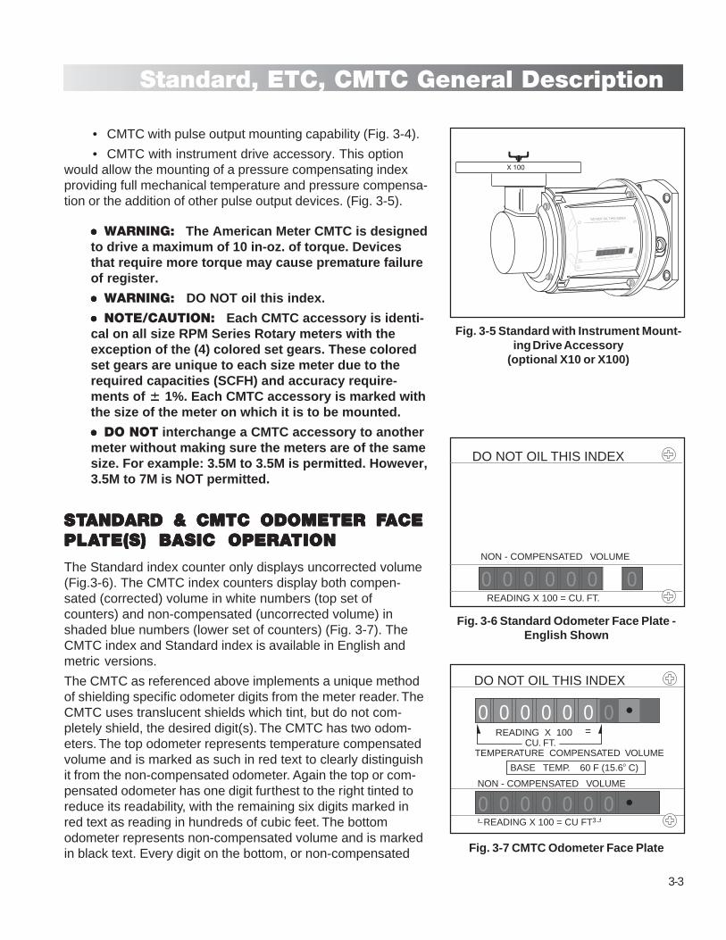
• CMTC with pulse output mounting capability (Fig. 3-4).
• CMTC with instrument drive accessory. This optionwould allow the mounting of a pressure compensating indexproviding full mechanical temperature and pressure compensa-tion or the addition of other pulse output devices. (Fig. 3-5).
●●●●● WARNING: The American Meter CMTC is designedto drive a maximum of 10 in-oz. of torque. Devicesthat require more torque may cause premature failureof register.
●●●●● WARNING: DO NOT oil this index.
●●●●● NOTE/CAUTION: Each CMTC accessory is identi-cal on all size RPM Series Rotary meters with theexception of the (4) colored set gears. These coloredset gears are unique to each size meter due to therequired capacities (SCFH) and accuracy require-ments of ����� 1%. Each CMTC accessory is marked withthe size of the meter on which it is to be mounted.
●●●●● DO NOT interchange a CMTC accessory to anothermeter without making sure the meters are of the samesize. For example: 3.5M to 3.5M is permitted. However,3.5M to 7M is NOT permitted.
STSTSTSTSTANDARD & CMTC ODOMETER FANDARD & CMTC ODOMETER FANDARD & CMTC ODOMETER FANDARD & CMTC ODOMETER FANDARD & CMTC ODOMETER FACEACEACEACEACEPLAPLAPLAPLAPLATE(S) BASIC OPERATE(S) BASIC OPERATE(S) BASIC OPERATE(S) BASIC OPERATE(S) BASIC OPERATIONTIONTIONTIONTION
The Standard index counter only displays uncorrected volume(Fig.3-6). The CMTC index counters display both compen-sated (corrected) volume in white numbers (top set ofcounters) and non-compensated (uncorrected volume) inshaded blue numbers (lower set of counters) (Fig. 3-7). TheCMTC index and Standard index is available in English andmetric versions.
The CMTC as referenced above implements a unique methodof shielding specific odometer digits from the meter reader. TheCMTC uses translucent shields which tint, but do not com-pletely shield, the desired digit(s). The CMTC has two odom-eters. The top odometer represents temperature compensatedvolume and is marked as such in red text to clearly distinguishit from the non-compensated odometer. Again the top or com-pensated odometer has one digit furthest to the right tinted toreduce its readability, with the remaining six digits marked inred text as reading in hundreds of cubic feet. The bottomodometer represents non-compensated volume and is markedin black text. Every digit on the bottom, or non-compensated
Fig. 3-5 Standard with Instrument Mount-ing Drive Accessory
(optional X10 or X100)
Fig. 3-6 Standard Odometer Face Plate -English Shown
Fig. 3-7 CMTC Odometer Face Plate
BASE TEMP. 60 F (15.6o C)
NON - COMPENSATED VOLUME
TEMPERATURE COMPENSATED VOLUME
READING X 100 = CU FT3
READING X 100 CU. FT.
=
0 0 0 0 0 0
0 0 0 0 0 0 0
0
DO NOT OIL THIS INDEX
READING X 100 = CU FT
NON - COMPENSATED VOLUME
DO NOT OIL THIS INDEX
0 0 0 0 0 0 0
X 100
NON - COMPENSATED VOLUME
READING X 100 = CU. FT.
0 0 0 0 0 0 0
DO NOT OIL THIS INDEX
3-4
Standard, ETC, CMTC General Description
odometer, is tinted to reduce readability. The combination oftinting and clear marking makes it simple to read the correctvolume reading.
VERVERVERVERVERTICAL/HORIZONTTICAL/HORIZONTTICAL/HORIZONTTICAL/HORIZONTTICAL/HORIZONTAL INSTAL INSTAL INSTAL INSTAL INSTALLAALLAALLAALLAALLATIONTIONTIONTIONTION
All Standard and CMTC meters are capable of a vertical orhorizontal installation. In both cases, the odometer face plateon the temperature compensator aligns with the meter badgeon the body of the rotary meter. It is not possible to rotate themechanical temperature compensator separate from the meter.Should your application require the meter to function in anopposite gas flow direction, you will need to specify this whenplacing your order or see instructions on page 3-5.
Vertical position (vertical/downward flow of gas):Odometer face plate of the CMTC is facing the front of themeter, matching the meter badge serial number plate. TheCMTC is positioned left with respect to the meter.
Horizontal position (horizontal/left to right flow of gas):Odometer face plate of the CMTC is facing the top of themeter, matching the meter badge serial number plate. TheCMTC is positioned left with respect to the meter.
ADDITIONAL PULSE OUTPUTADDITIONAL PULSE OUTPUTADDITIONAL PULSE OUTPUTADDITIONAL PULSE OUTPUTADDITIONAL PULSE OUTPUTDEVICESDEVICESDEVICESDEVICESDEVICES
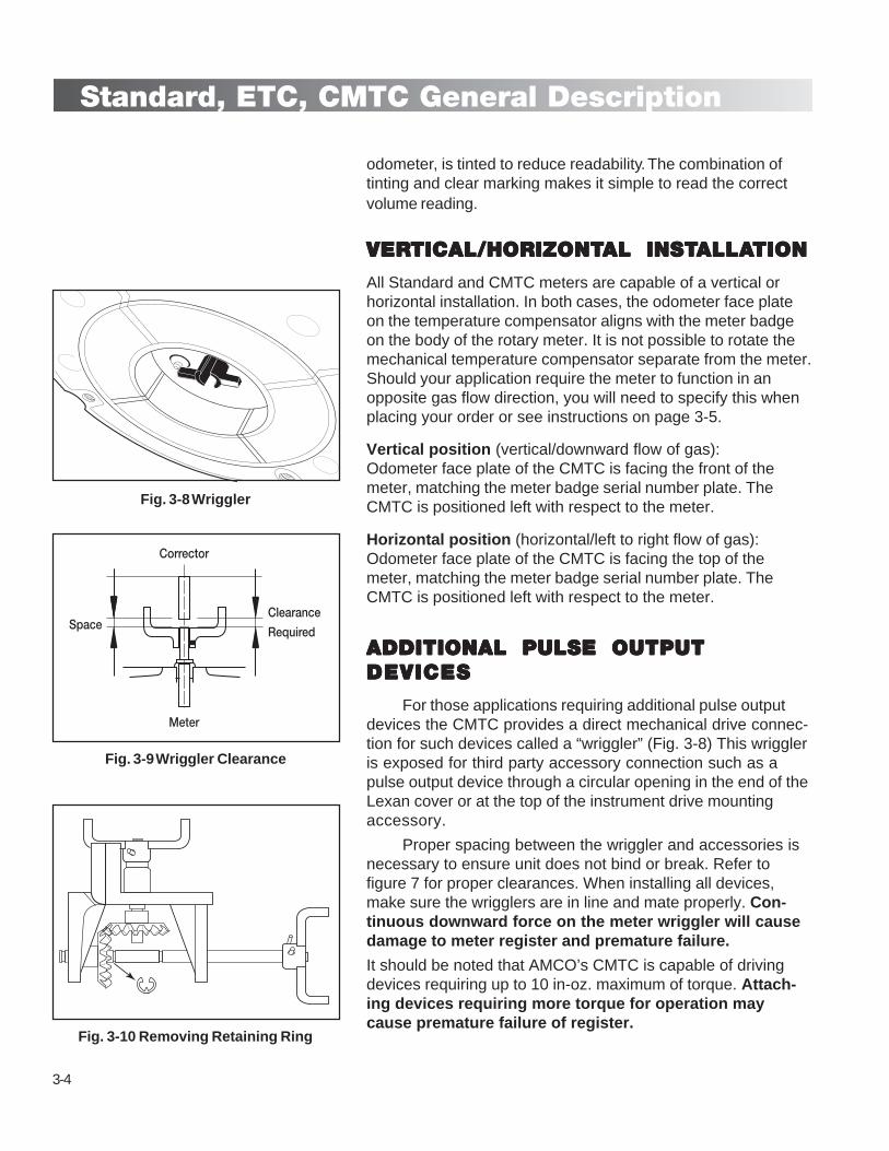
For those applications requiring additional pulse outputdevices the CMTC provides a direct mechanical drive connec-tion for such devices called a “wriggler” (Fig. 3-8) This wriggleris exposed for third party accessory connection such as apulse output device through a circular opening in the end of theLexan cover or at the top of the instrument drive mountingaccessory.
Proper spacing between the wriggler and accessories isnecessary to ensure unit does not bind or break. Refer tofigure 7 for proper clearances. When installing all devices,make sure the wrigglers are in line and mate properly. Con-tinuous downward force on the meter wriggler will causedamage to meter register and premature failure.
It should be noted that AMCO’s CMTC is capable of drivingdevices requiring up to 10 in-oz. maximum of torque. Attach-ing devices requiring more torque for operation maycause premature failure of register.
Fig. 3-8 Wriggler
Fig. 3-9 Wriggler Clearance
Corrector
Meter
SpaceClearance
Required
Fig. 3-10 Removing Retaining Ring

3-5
Standard, ETC, CMTC General Description
WRIGGLER ROTWRIGGLER ROTWRIGGLER ROTWRIGGLER ROTWRIGGLER ROTAAAAATION DIRECTIONTION DIRECTIONTION DIRECTIONTION DIRECTIONTION DIRECTION
Illustration shown is 1:1 gear ratio. The factory defaultrotation direction of the wriggler is in a clockwise directionwhen looking down on the Instrument Drive from above.Should the installation of your pressure correcting or pulseoutput device require counter clockwise rotation of thewriggler, follow the procedure below. Before attaching theInstrument Drive, loosen the (2) socket head cap screwsholding the angle bracket assembly to the inside of theInstrument Drive and remove from the Instrument Drivehousing. Remove the retaining ring from the metal shaft (Fig.3-10). Slide the angle bracket to the right (Fig. 3-11 (1)) Nextslide the shaft to the right (Fig. 3-11 (2)) being careful not tolose the nylon gear riding on shaft. Remove the nylon gear(Fig. 3-11 (3)). Flip gear horizontally and replace on shaftmaking sure the flat machined surface of the shaft mates withcorresponding flat on inside of gear. Reattach retaining ring tothe left of gear (Fig. 3-12). Next, slide the right side of anglebracket back to its original position ensuring its alignment withgrooved surface just above the top gear (Fig. 3-12). Note: theshaft will follow in this step. Make sure it aligns properly withcorresponding hole in left angle bracket. Finally, remount theangle bracket assembly into the Instrument Drive housing andinstall housing to CMTC.
REVERSE FLOW CONVERSIONREVERSE FLOW CONVERSIONREVERSE FLOW CONVERSIONREVERSE FLOW CONVERSIONREVERSE FLOW CONVERSION
All meter sizes come shipped from the factory withcomponents which will allow for the conversion to reverse flowapplication. To convert a new meter from standard gas flowconfiguration to reverse flow configuration (upward or right-to-left)(Fig. 3-17), follow all instructions below carefully. Shouldyou have an older RPM Series rotary gas meter which needsto be converted for reverse flow application, contact AmericanMeter Company for a Reverse Flow Kit (see page 3-7).
WARNING: If meter is in service, it must be depressurizedand oil drained from the drive side case cover.
Step 1: Remove metric socket head cap screws from casecover and set aside. (Fig. 3-13) During cover removal, therubber O-ring may fall loose. If so, simply reinstall it into thegroove on the underside of the case cover.
Step 2: Remove the 1/16" allen head screw and magnet holder.(Fig. 3-14)
Step 3: Loosen set screw and remove spur gear with roll pin/
Fig. 3-10 Removing Retaining Ring
Fig. 3-11 Repositioning of Gear
1
2
3
3
3
Fig. 3-12 Replacing Retaining Ring
4
5

3-6
Standard, ETC, CMTC General Description
A
B
C
oil slinger (B) from bottom impeller shaft. (Fig. 3-14)
Step 4: Loosen set screw and remove oil slinger hub (C) fromtop impeller shaft. (Fig. 3-14)
Step 5: Install oil slinger (B) that had been removed frombottom shaft in step 3, on opposite impeller shaft (top), sliding ittowards the meter body until the gears properly engage. (Fig.3-15) Tighten set screw to 15 in-oz.
Step 6: Install oil slinger hub (C) that had been removed fromtop shaft in step 4, on opposite impeller shaft (bottom). Tightenset screw to 15 in-oz. (Fig. 3-15)
Step 7: Reinstall magnet holder assembly with allen headscrew using Loctite 222 to the centering shaft threads. Tightenflat head screw to 15 in-oz. (Fig. 3-16)
Step 8: Rotate the meter impellers to assure that properassembly has been made.
Step 9: Remount case cover making sure that its sealing O-ring is properly in its groove. Install four socket head capscrews and tighten to 100 in-lbs. for 9.0C and 1.5M meters or150 in-lbs for 3.5M, 5.5M, 7M or 11M meters.
Step 10: Orient manufacturer’s badge to show gas flowarrow to the adjusted direction.
Step 11: Refer to Instruction Manual IM 5750 supplied withmeter to continue with standard rotary mounting instructions.
Reverse Flow kits are available for older meters in thefield by ordering the part numbers as listed in the table on page3-7.Note: Each reverse flow kit contains oil slinger/hub, associatedset screw for mounting and new meter badge.
PROVING OPERATIONS
The permanently lubricated Continuous MechanicalTemperature Compensator (CMTC) provides a means forconvenient standard-scanning methods used for performingmeter proving. The adjustment of the compensated odometer iscontinuous therefore, does not require consideration of adjust-ment bursts provided in some devices. The odometer wheelpositioned at the right hand side next to the 10 cu. ft. numberwheel on both odometers, non-compensated and compen-sated, can be scanned through the number wheel aperture ofthe odometer housing. The odometer wheels, also referred to
Fig. 3-13 Removing Case Cover
Fig. 3-14 Removing Magnet Assembly (A),Oil Slinger (B) & Oil Slinger Hub (C)
Fig. 3-15 Replacing Oil Slinger (B) to topshaft & Oil Slinger Hub (C) to bottom
Fig. 3-16 Replacing Magnet Assembly
A
C
B
1/16" allen head screw

3-7
Standard, ETC, CMTC General Description
as proving wheels, provided for scanning, feature a whitesquare “target-mark” used for scanning. One revolution ofboth wheels, non-compensated and compensated, repre-sents 10 cubic feet (between the target-mark on the wheels).Accessibility for scanning through the clear plastic cover isprovided.
An alternate volume scanning is provided for the com-pensated volume at the CMTC center drive shaft couplingvisible and accessible for scanning through the clear area ofthe cover end face. The coupling features a white “targetmark” that provides 10 cubic feet compensated volumebetween two target-marks representing one revolution. Thevolume per revolution of the odometer wheels and centerdrive used for scanning is identical for all meter sizes.
Proving the CMTC Meter on a Dresser Model 5 Trans-fer Prover (Corrected Volume)
There is no need to remove the CMTC Lexan cover.Place the optical sensor in position to read the 10 ft. provingwheel on the far right of the Corrected Volume odometerfaceplate. The proving wheels of both odometers feature reddots in 1 cubic foot increments, a red rectangle 5 cubic footmark, in addition to the white square “target-mark” to easevisual verification of rotation. Connect the upstream anddownstream pressure taps. Connect the temperature probeto the upstream side.On the Roots PC Prover executable file:1. Configure and run a meter test
2. Prover Capacity: 2M, 5M, 10M, 80M (select one capacitydepending on the size of meter to be tested)
3. Test Control Mode: ID OPTO or Manual (select one de-pending on the type of pick-up being used.Ex.: OPTO= optical pick-up)
Fig. 3-17 Gas Flow Diagram For Reverse Flow Configuration
BASE TEMP. 60 F (15.6o C)
NON - COMPENSATED VOLUME
TEMPERATURE COMPENSATED VOLUME
READING X 100 = CU FT3
READING X 100 CU. FT.
=
0 0 0 0 0 0
0 0 0 0 0 0 0
0
Horizontal Flow Configuration(Right to Left)
Vertical Flow Configuration(Upward))
Meter Kit Part Number
8.0C 52918K0019.0C 52918K00111C 52918K0011.5M 52918K0012M 52920K0073.5M 52920K0075.5M 52921K0017M 52932K00111M 52945K00116M N/A
Reverse Flow Kits

3-8
Standard, ETC, CMTC General Description
4. Meter Output: UC, TC, PC, PCTC select Diaphragm TC(continuously compensated)
5. Pulses/Test Volume: 2 Pulses, 20 cu. ft. minimum (recom-mended depending on size of meter)
6. Flow Rates: 100%, 60%, 30%, 10% (recommended)Ref. 1.5M meter capacities: 1500, 900, 450, 150
7. Base Temperature: 600 F.
8. Conduct the test.
Temperature-Compensating AccuracyThe CMTC accessory can provide a temperature correct-
ing accuracy of gas volume within +/-0.5% with respect to thetheoretical correction for a flowing gas temperature range of -20° F to 120° F. The accuracy test of the CMTC accessory isdetermined by operating the device with the temperaturetransducer sense bulb submersed in a temperature stabilizedbath using test points according to ANSI B109.3 Para.6.12.1.2.3 Type III.
A combined accuracy test, meter with CMTC accessory,at flowing gas temperature according to ANSI B109.3 Para.6.12.1.2.1 Type I is a standard factory test. Attainable com-bined accuracy over a range of 20° F to 100° F is within +/-1%.
CMTC Operational Check1. Using an accurate certified temperature-measuring device,
record the stabilized gas (or air) temperature flowing directlyinto the meter inlet port.
2. Compare that reading to the acclimated meter’s CMTCindicating temperature dial on the front of the meter underthe lexan cover. Both readings should agree within +/- 40 F.
3. Example A) If both readings were the same i.e. 600 F (15.60
C) and a volume of 200 ft3 was ran across the meter, boththe uncorrected and corrected register readings would bothincrease by 200ft3. Reason why? All commercially used,non-temperature compensated natural gas meters aredesigned to measure gas flow(s) at 600 F (15.60 C). There-fore, a temperature compensated meter at 600 F (15.60 C)should measure the “same increase in volume” on both of itscorrected and uncorrected register displays.
4. Using Charles Law (Basic Gas Laws) which states theVolume of given mass of gas is directly proportional to itsabsolute temperature with the equation:(Where 600 F = 5200 on the Rankine temperature scale)
Base Temp Rankine
Gage Temp (F degrees) + 4600 F = Volume Multiplier

3-9
Standard, ETC, CMTC General Description
Therefore:
600 F + 4600 F = 520 R (base temp.)
600 F + 4600 F = 520 R (gage temp.)
5. Example B: Using the above equation with a temperaturevariant from 600 F base Temperature. Lets say the air flowinginto the meter is ambient shop air with the meter also accli-mated to 720 F (22.20 C).
Therefore:
600 F + 4600 F = 520 R
720 F + 4600 F = 532 R
If you ran 200 ft3 across the meter at 720 F, your uncorrectedreading would show a 200 ft3 increase whereas the temp-erature corrected reading would only increase by 195.4 ft3 (200X .977).
6. Remember, the colder the gas (air) temperature from 600 Fbase temperature, the greater the Volume Multiplier will be.Example: Using 400 F (4.40 C) gas or shop air;
Therefore:
600 F + 4600 F = 520 R
400 F + 4600 F = 500 R
If you ran 200 ft3 across the meter at 400 F, your uncorrectedreading would show a 200 ft3 increase whereas the temp-erature corrected reading would increase to 208 ft3 (200 X 1.04).
METER SHOP TEST PROCEDURESA meter shop motor driven test fixture will be needed for
the following test procedure. Place the case cover/bulb andbellows transducer/temperature compensator assembly in atemperature bath to regulate the transducer temperature withrecirculating fluid. (Fig. 3-18)
Set the motor on the test fixture to engage the spur geardriving the cylinder. Position the photogate sensors to read theproving wheels (white bar with no numbers) on the compensatedand uncompensated indices. These sensors are to be con-nected to electronic counters that display the time between eachrotation of the proving wheel.
600 Temperature BathSet the bath temperature to 600 F. Set the motor output
speed on the test fixture to approximately 350 R.P.M. Zero thecounters and record the time for each index to count pulses asindicated on the following page.
= 1 (Volume Multiplier)
= .977 (Volume Multiplier)
= 1.04 (Volume Multiplier)

3-10
Standard, ETC, CMTC General Description
Temperature Error Factor9.0C 3 counts 100.59 seconds1.5M 3 counts 107.8 seconds3.5M 3 counts 109.5 seconds5.5M 3 counts 102.9 seconds7.0M 5 counts 100.8 seconds11.0M 5 counts 102.48 seconds
+ Error = Over-registration - Error = Under-registration
Adjusting for Temperature Error FactorIf the Corrected counter is indicating a faster time than
the Uncorrected counter, loosen the #4-40 socket head capscrew (A) in the adjustment bracket and turn the adjustmentcollar (B) clockwise. (Looking at the hex face as shown in Fig.3-19) If the Corrected counter is indicating a slower time thanthe Uncorrected counter, turn the adjustment collar counter-clockwise.
Three quarters (3/4) turn of the adjustment collar resultsin an error exchange of approximately 1%. Tighten the #4-40Socket head cap screw after the adjustment is made. Again,zero the counters and record the time for each index to countpulses as listed in the Temperature Error Factor table above.
Reset the counters to count 50 pulses and record theaverage temperature over the length of the test.
Calculate the temperature factor error from the table onthe previous page. If the error is less than +/- 0.75% the cali-bration process for this temperature bath is complete. If theerror is equal to or greater than +/-0.75%, repeat the adjust-ment procedures on the adjustment bracket and recalculatetemperature error factor.
00 Temperature BathSet the bath temperature to 00 F. Keep the motor output
speed on the test fixture at approximately 350 R.P.M. Zero thecounters and record the time for each index to count appropri-ate number of pulses for the meter size. An acceptable tem-perature error factor is less than +/- 0.85%. If the error factorexceeds this rate, repeat the steps in Adjusting for Tempera-ture Error Factor above.
1200 Temperature BathSet the bath temperature to 1200 F. Keep the motor output
speed on the test fixture at approximately 350 R.P.M. Zero thecounters and record the time for each index to count appropri-ate number of pulses for the meter size. An acceptable tem-perature error factor is less than +/- 0.67%. If the error factorexceeds this rate, repeat the steps in Adjusting for Tempera-ture Error Factor above.
Fig. 3-18 Meter Shop Test Fixture
100
Clockwise for DECREASINGspeed.
Counterclockwise for INCREASING speed.
BA
Fig. 3-19 Adjustment Bracket & Collar

4-1
Inspection & Maintenance
MAINTENANCE
The following items should be inspected during routine fieldvisitations to the meter site:
• Listen for abnormal sounds in the meter such as squeaksor grinding.
• Check all pertinent oil level sight plugs for correct volumeand black or gray oil discoloration.
• Analyze the meters general condition: look for damage tothe outer case due to vandalism, vehicles, weld burns,steam/water drippage, etc. Is there indication of excessivevibration?
• Is the meter still level within +1/16" per foot in all directionalplanes?
• Is there any deformation or strained inlet-outlet piping?
• Examine and clean all upstream strainers and filters.
• Check the rotary meter drive output for binds, i.e.,ratcheting movement, no registration.
• Check the instrument drive for binds.
• Check the temperature compensator for accuracy, digitaldisplay, battery life remaining, and low battery warnings.
• Clock the meter for passage of predetermined volume ofgas by using the dial on the register with the stop watch.
• Differential pressure test @ 20%, 50% and 80% using aaccurate test gauge.
Record all pertinent data on the maintenance record included inthe Appendix.

4-2
Inspection & Maintenance
PROBLEM PROBABLE CAUSE SUGGESTED ACTION
Excessive vibration: Build-up of foreign material Clean by flushing or replacement of
on impellers replacement of parts
Misalignment Level Meter
Worn Bearings Replace/return to meter shop
Worn Gears Replace/return to meter shop
Impellers contacting body Rotate manually to verify free spin.
Remove obstructions. Check for level.
High Differential Heavyweight or too much oil? Check level and condition
Dirt deposits on impellers Remove dirt by flushing
Impellers out of time Retime impellers. Remove and return to
shop for disassembly
Impellers contacting body Rotate manually to verify free spin
Low Registration Upstream or bypass leak Check all valves for leakage
Non Registration Drive pin has sheared to Check for sheared pin
accessory unit
Bind in the accessory unit Start and stop meter; if counter or
instrument does not operate, there is
accessory failure.
Obstruction within meter or Remove obstructions to
associated piping rotation or flow. Remove meter and
flush as necessary.

5-1
Instrument Drive
X 100
0 0 0 0 0
DO NOT OIL THIS INDEX
The following accessories are available from American Meterfor the American RPM Series Rotary Meter. Only qualifiedtechnicians should attempt installation procedures to the meteror the accessory unit. The American Meter Company canassist you with all rebuilding or repair of your meter at ourfactory. Part prices are available upon request.
To order parts for the meter or accessory, please contact yoursales office and be prepared to specify the following informa-tion:
METERS- Model No. (Example 3.5M), Serial No. (Frombadge) 96 C0000149.
ACCESSORY-Model No. (Example 3.5M), Type of Unit(Temperature Compensator)
INSTRUMENT DRIVE ACCESSORY KIT
The addition of an instrument drive accessory to an existingRPM Standard or CMTC Rotary meter require the replacementof the existing Lexan register cover with one allowing accessto the wriggler drive. For more information contact your salesoffice. To install the instrument drive remove the four (4) allen-head screws which secure the clear lexan cover and replacewith register cover having wriggler access. Make sure thelargest clear window is placed over register counter(s). Tighten4 screws.
The Instrument drive kit will include the drive, O-ring and 4allen-head mounting screws. Install the O-ring over the shoul-der of the Lexan cover and place the instrument drive unitagainst Lexan cover to allow proper alignment of mountingholes. Install 4 supplied allen head screws and tighten (Fig. 5-1). Take care not to over tighten.
Fig. 5-1 Installing Instrument Drive Kit(optional X10 or X100)

5-2
Instrument Drive
00
3150
2250 1350
1800
2700
00
3150
2250 1350
9002700
(4) ThreadedInstument Drive Mounting Holes(in Universal Top Plate)
Universal Top PlateMounting Holes (to Register Housing)
(4) Threaded Mounting Holes (in Register Housing)
Register Housing
Universal Top Plate
Top ViewUniversal Top Plate & Register Housing
Register HousingInstrument
Drive Shaft& Gearing
Instrument Drive Shaft & GearingMounting Holes (to Register Housing)
Universal Top Plate180o
Register Housing
CORRECTED VOLUMEMCF
0 0 0 0 0 0 0 0
NON - COMPENSATED VOLUME
READING X 100 = CU FT3
0 0 0 0 0 0 0
Optional Instrument Drive Kit(s).
4 different options which should be clarified prior to placingorders:
• 1:1 (X10) Clockwise wriggler rotation - Kit # 52994K051
• 1:1 (X10) Counter-clockwise wriggler rotation -
Kit # 52994K052
• 10:1 (X100) Clockwise wriggler rotation - Kit # 52994K053
• 10:1 (X100) Counter-clockwise wriggler rotation -
Kit # 52994K054
Optional Instrument Drive and Corrector Installation.The Instrument Drive Kit can be rotated 3600 on the meterproviding 8 different locations allowing for vertical positioning ofthe Corrector.

6-1
Appendix
Line
sP
ress
.G
asTe
mp
.S
p.
Gra
v.Vo
lum
eM
easu
red
Run
Tim
e
Rat
eC
FH
(m3/
h)D
ate
Test
erIn
s. W
.C.
% C
hg.
Diff
. Pre
ssur
e
(mm
W.C
.)
INIT
IAL
TE
ST
S -
NE
W M
ET
ER
DIF
FER
EN
TIA
L-R
AT
E T
ES
T D
ATA
Met
er M
od
elU
tility
Ser
ial N
o.
Ser
ial N
o.
Loca
tion
Reg
iste
r R
ead
ing
Dat
e In
stal
led
PE
RIO
DIC
CH
EC
K L
IST

6-2
Appendix
MA
INT
EN
AN
CE
RE
CO
RD
Met
er M
od
el
Dat
eS
ervi
ce
Ser
ial N
o.

6-3
Appendix

6-4
Appendix
MERCURY INSTRUMENTS INC.3940 Virginia AvenueCincinnati, OH 45227 U.S.A.Phone 513-272-1111Fax: 513-272-0211www.mercuryinstruments.com
mi
Measurement Engineers Since 1836
Turbine Gas MetersHigh performance meters provide accurate measurement of high volume gas flow. Turbines are available from 3" to 12" line sizes and line pressure up to 1440 psig. See bulletin SB 4510 for more information.
Pre-Calibrated Replacement CartridgesTested at atmospheric or actual operating pressure, pre-calibrated measurement cartridges are available for field service changes. Cartridges returned to the factory for re-certification and/or service are tested at five flow rates and at specified pressure.
Rotary Meter with Prefabricated SetsPrefabricated new or replacement meter sets to customer specifications are available.
Diaphragm MetersAmerican Meter’s compact, lightweight, aluminum case meters are designed to provide positive displacement accuracy for industrial or commercial loads. See bulletin SB 3510 for more information.
Pilot-Loaded Regulators1800 PFM industrial regulators are designed for applications requiring medium-to-high capacity, extremely precise outlet pressure control, and fast response to changing loads. See bulletin SB 8551 for more information.
FiltersFiltration down to 10 microns. Protects meter and regulator stations from dirt and pipe scale damage. See bulletin SB 12521 for more information.
A Complete Family of Gas Measurement, Pressure Regulation, and Filtration Systems
Represented by:
©2005 American Meter Company 09/05 2M A&A AMCO\IM5700.4 Printed in U.S.A.
American Meter Company has a program of continuous product development and improvement; and, therefore, the information in this bulletin is subject to change or modification without notice.