Embed Size (px)
Citation preview

Frontline Technical Support: Phone +1-434-984-4500 or email [email protected]
TM Quick StartGuide
Computer System RequirementsSupported Systems
l Operating System: Windows 7/8/10l USB:USB 2.0 and later
Minimum Requirementsl Processor: Core i5 at 2.7 GHzl RAM: 4 GBl Free Hard Disk Space on C: drive: 20 GB
Install Software
l From Download: Download the latest ComProbe installerfrom FTE.com. Once downloaded, double-click theinstaller and follow the directions.
http://www.fte.com/sodera-soft
1. Front Panel Controls
Frontline Sodera™ front panel is shown below. The panel provides controls to power up and shut down the Frontline Sodera hardware,and it provides indicators to show the power, battery, and capture status.
Sodera Front Panel Controls and Indicators
Frontline Technical Support: Phone +1-434-984-4500 or email [email protected]
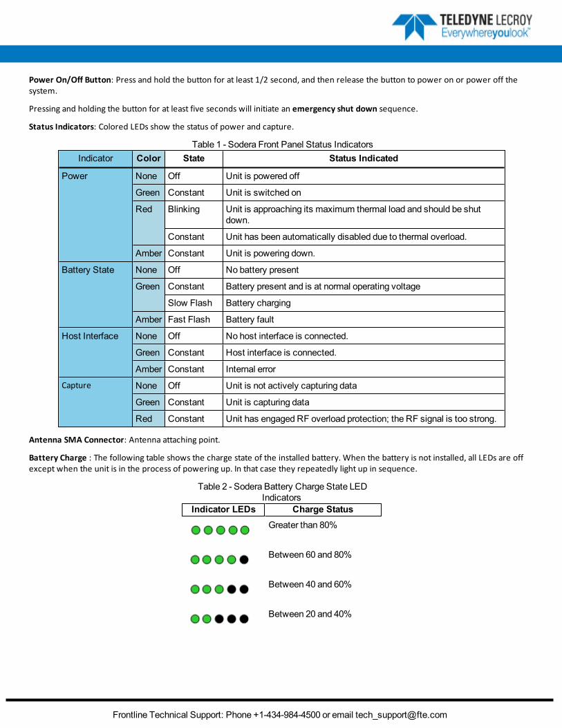
Power On/Off Button: Press and hold the button for at least 1/2 second, and then release the button to power on or power off thesystem.
Pressing and holding the button for at least five seconds will initiate an emergency shut down sequence.
Status Indicators: Colored LEDs show the status of power and capture.
Indicator Color State Status Indicated
Power None Off Unit is powered off
Green Constant Unit is switched on
Red Blinking Unit is approaching its maximum thermal load and should be shutdown.
Constant Unit has been automatically disabled due to thermal overload.
Amber Constant Unit is powering down.
Battery State None Off No battery present
Green Constant Battery present and is at normal operating voltage
Slow Flash Battery charging
Amber Fast Flash Battery fault
Host Interface None Off No host interface is connected.
Green Constant Host interface is connected.
Amber Constant Internal error
Capture None Off Unit is not actively capturing data
Green Constant Unit is capturing data
Red Constant Unit has engaged RF overload protection; the RF signal is too strong.
Table 1 - Sodera Front Panel Status Indicators
Antenna SMA Connector: Antenna attaching point.
Battery Charge : The following table shows the charge state of the installed battery. When the battery is not installed, all LEDs are offexcept when the unit is in the process of powering up. In that case they repeatedly light up in sequence.
Indicator LEDs Charge StatusGreater than 80%
Between 60 and 80%
Between 40 and 60%
Between 20 and 40%
Table 2 - Sodera Battery Charge State LEDIndicators

Frontline Technical Support: Phone +1-434-984-4500 or email [email protected]
Indicator LEDs Charge StatusLess than 20%
Not Active
Table 2 - Sodera Battery Charge State LED Indic-ators(Continued)
Excursion Mode: When configured for Excursion mode, pressing this button will begin data capture—the same as theRecord/Recording button on the SoderaWindow Capture Toolbar. The Excursion Mode button is inactive when Sodera is connected toa computer . To operate in the Excursion mode, the Sodera hardware must have been previously configured from the Frontlinesoftware prior to disconnecting from the computer. The Sodera hardware will retain those configuration settings when disconnectedfrom the computer. Refer to the Frontline Sodera User Manual for Excursion mode operating details.
2. Rear Panel Connectors
The rear panel is shown below. The panel provides connectors for external power, ProbeSync™, HCI, and for connection to thecomputer hosting the Frontline software.
Sodera Rear Panel Connectors
+12VDC: Connection to the Frontline supplied AC-to-DC power adapter, or a 12 VDC auxiliary vehicle outlet system can be used.
ProbeSync™ IN/OUT: Used for synchronizing multiple capture devices. Sodera can act as a clock source (master) device providing theclock to synchronize timestamping with connected target (slave) devices. When operating as a master device the OUT RJ-45 connectorprovides the synchronizing clock. The synchronizing clock can be attached to a slave Frontline Sodera or a Frontline 802.11, forexample. When operating as a slave device, the IN RJ-45 connector receives the synchronizing clock from amaster Sodera unit.
HCI USB 1/HCI USB 2:USB Type B and a USB Type A connectors allow capture of HCI USB data. HCI USB 1 and HCI USB 2 areindependent groupings of the Type A and Type B connectors. The HCI USB 1 connectors use the same Sodera unit internal interface asthe Sodera HCI POD1 UART pins. Likewise the HCI USB 2 connectors use the same internal interface as the Sodera HCI POD2 UART pins.Therefore you cannot simultaneously capture USB and UART on the "1" interface or on the "2" interface. Refer to 1.1 Connecting forUSB Capture, on page 1 and to 1.1 Connecting for HCI Capture, on page 1.
PC HOST : USB 2.0 port for connecting Sodera to the host computer where the Frontline software resides. This connector provides hostcomputer command, control, and data transfer.
Note: At this time all other rear panel connectors are inactive.
Frontline Technical Support: Phone +1-434-984-4500 or email [email protected]
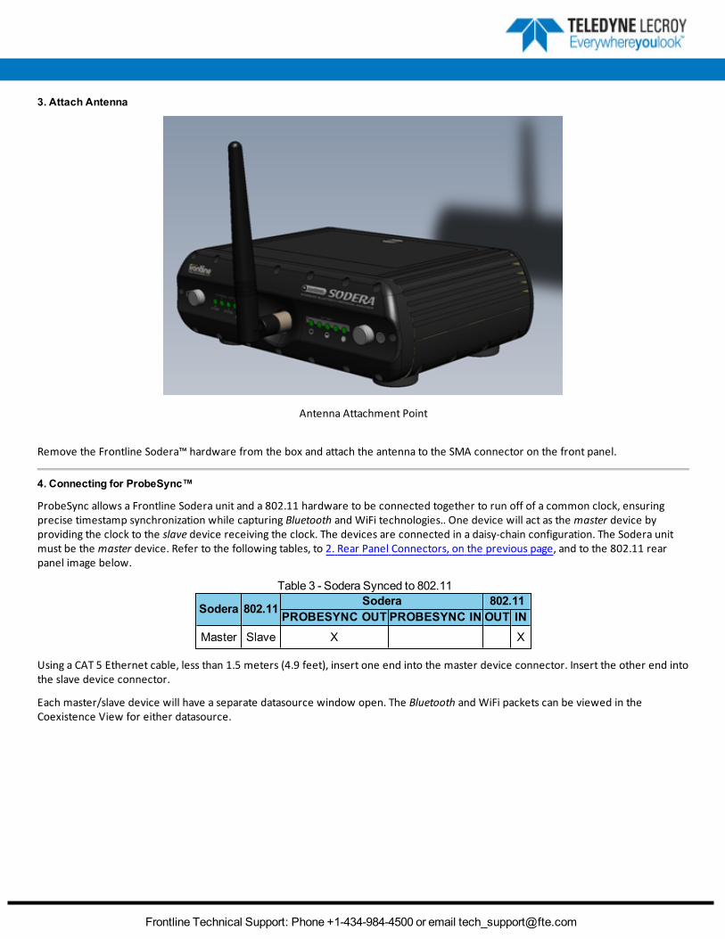
3. Attach Antenna
Antenna Attachment Point
Remove the Frontline Sodera™ hardware from the box and attach the antenna to the SMA connector on the front panel.
4. Connecting for ProbeSync™
ProbeSync allows a Frontline Sodera unit and a 802.11 hardware to be connected together to run off of a common clock, ensuringprecise timestamp synchronization while capturing Bluetooth and WiFi technologies.. One device will act as the master device byproviding the clock to the slave device receiving the clock. The devices are connected in a daisy-chain configuration. The Sodera unitmust be the master device. Refer to the following tables, to 2. Rear Panel Connectors, on the previous page, and to the 802.11 rearpanel image below.
Sodera 802.11 Sodera 802.11PROBESYNC OUT PROBESYNC IN OUT IN
Master Slave X X
Table 3 - Sodera Synced to 802.11
Using a CAT 5 Ethernet cable, less than 1.5 meters (4.9 feet), insert one end into the master device connector. Insert the other end intothe slave device connector.
Each master/slave device will have a separate datasource window open. The Bluetooth and WiFi packets can be viewed in theCoexistence View for either datasource.

Frontline Technical Support: Phone +1-434-984-4500 or email [email protected]
ComProbe 802.11 Back Panel
5. Applying Power
The Sodera hardware is powered by three methods: the Frontline supplied AC-to-DC adapter, an external DC power source that caninclude power from an automobile auxiliary power source and an optional internal battery.
To apply power to Sodera use one of the three methods:
1. Connect the provided AC-to-DC power adapter to the +12VDC connector on the rear panel and then connect the adapter intoan AC source.
2. Connect a DC power source supplying +12 VDC directly to the +12VDC connector on the rear panel.3. Install the battery.
To start Sodera , depress the Power button on the front panel for at least 1/2 second and then release . This action will provide a cleanstart for Sodera hardware. The battery charge state indicator LEDs will repeatedly flash in sequence while the unit powers up.
The front panel Power indicator LED will be green.
Should the front panel Power indicator begin blinking red, the Sodera hardware is approaching thermal overload temperaturebetween 50 °C and 60 °C (122 °F and 140 °F) and should be shut down. When the hardware reaches thermal overload it willautomatically shut down and the Power indicator will be a constant red.
6. Sodera Data Capture Method
When the Frontline Sodera is connected to the Host PC running Frontline Protocol Analysis System software the Select Data CaptureMethod...window will display the Sodera options.

Frontline Technical Support: Phone +1-434-984-4500 or email [email protected]
Sodera Data Capture Method
SelectWideband Bluetooth, Bluetooth Classic/low energy (Frontline Sodera)
Click on Run. The Frontline software will display the Sodera Controlwindow.
Sodera Control Window
7. User Configuration Overview
Frontline® Sodera™ is capable of simultaneously capturing and demodulating all RF channels and packet types defined in all Bluetoothspecification versions up to and including 4.2. The user is not required to specify the addresses of the devices to be captured or theirroles (master or slave) during the connection lifetime. Prior to capturing data the user does not need to enter any information (PIN,OOB, long term key, link key) used to encrypt or decrypt data. Sodera provides live simultaneous capture of all 79 Classic Bluetoothchannels and 40 Bluetooth low energy channels storing data for both live and post-capture analysis.
Sodera™ uses a two-stage capture-analysis process. First, Recordwill activate the Sodera™ datasource to begin capturing data from allBluetooth devices in range. In the Analyze stage, the user selects one or more wireless or wired devices for analysis and Sodera™ will

Frontline Technical Support: Phone +1-434-984-4500 or email [email protected]
begin sending captured data that is to/from those devices to the Frontline analysis software. The data appears in the Frame Display,Message Sequence Chart, Coexistence View, Bluetooth Timeline, low energy Bluetooth Timeline, PER Stats, Event Display etc.
If any keys needed for decryption are known from past captures those keys are automatically applied to the devices under test. Prior toprotocol analysis the user can enter any unknown keys. Sodera will identify the specific key necessary for data decryption, for exampleLink Key, Passkey, PIN, Temporary Key. Decryption keys are entered into the Sodera Security Pane
Sodera Security Pane
The user can configure the datasource from the Options menu. The default settings are sufficient for capturing most Bluetoothconnections. Details of the configuration settings are in the Frontline Sodera User Manual available for download from FTE.com or inFrontline Sodera on-line help.
SoderaWindow

Frontline Technical Support: Phone +1-434-984-4500 or email [email protected]
8. Set in Target: Record—Begin Capture
When starting a capture session
l the active status of all devices is cleared in theWireless Devices andWired Devices panes ,l the Security pane is emptied, andl the Event Log pane retains all prior logged events.
On the Capture Toolbar, click on the Record button, or selectRecord from the Capture menu option. Whenthe Record button changes to Recording, Sodera hardware is capturing data from all active Bluetooth deviceswithin range and is recording data on the PC.
On the Capture Toolbar, clicking on the Recording button, or selecting Recording from the Capture menuoptions will halt live capture.
TheWireless Devices andWired Devices pane populates with any newly discovered devices. Selectingdevices for analysis can be done while recording.
Note: The Capture ToolbarAnalyze button will be grayed out until somewireless devices have been selected foranalysis.
The Security pane will show all encrypted Bluetooth links.
The Event Log pane will begin to populate with information, warnings, and error messages.
The Status Bar will show a running total of captured packets.
Note: Starting a new capture session will clear all unsaved data from both the Set in Target hardware and theFrontline software. If it has not been saved, then a pop-up warningmessage will appear.
9. Set in Target: Selecting Devices for Analysis
Once a Set in Target capture session starts by clicking on Record on the Capture Toolbar, data from all active devices within range ordata from wired connections is being captured. To analyze the data using the Frontline software, you select specific devices of interestto include in the analysis.
Set in TargetWireless Devices Pane

Frontline Technical Support: Phone +1-434-984-4500 or email [email protected]
In theWireless Devices andWired Devices pane, place a check in the row of each active device / to be analyzed. Active
devices can also be selected while the recording is in process.
Note: Data filtered by the device selection is an “OR” function, not an “AND” function. When selecting device1,device2, device3,... the recorded data filtered into the analyzer is data involving device1OR device2OR device3OR .... However, if in the Options menu, analysis if LE Empty packets is selected an AND function is included.For example: (device2 AND LE Empty packets) OR (device3 AND LE Empty packets).
The following table lists some common data capture and device selection scenarios.
Scenario Wireless Devices Pane SelectionAnalyzing traffic between a slave Device Under Test(DUT) and its master.
Select only the slave DUT for analysis
Analyzing all traffic on a piconet Select theMaster for analysis
Analyzing all traffic involved in Inquiries In the Set in TargetOptions menu select Analyze Inquiry ProcessPackets in theOptionsmenu
Table 4 - CommonData Capture and Device Selection Scenarios
The Set in Target is now ready to begin protocol- and event-level analysis.
10. Set in Target: Starting Analysis
The analysis begins by clicking on the Analyze button, or selecting Analyze from the Capture menu.Alternatively, click on the Start Analyze button In the Controlwindow. The Set in Target hardware will
begin sending captured packets involving the selected device to the Frontline software.
Once analysis has begun, you cannot change the device selection. All device rows in theWireless Devices andWired Devices pane are grayed-out. To stop the analysis, click on the Analyzing button. You can then changeyour device selection and restart analysis by clicking on the Analyze button.
To stop the Analysis click on the Analyzing button or click on the Controlwindow Stop Analyze button .
Conducting analysis from a capture file is identical to the live capture method.
11. Capturing Set in Target Analyzed Data to Disk
Note: Record is not available in Viewermode. Analyze/Analyzing is available in Viewermode, allowing differentanalyses to be performed on previously recorded and saved captures.
1. Click the Record button on the Standard Toolbar. Sodera will begin capturing data from all wireless devices
within range and from all connected wired devices.2. In theWireless Devices andWired Devices pane select the active devices for analysis3. Click on Analyze button , or click the Start Analyze button to begin capturing to a file. This Start Analyze
button is located on the Controlwindow, Event Display, and Frame Display.4. Files are placed in My Capture Files by default and have a .cfa extension. Choose Directories from the Options menu on the
Controlwindow to change the default file location.5. Watch the Status Bar on the Controlwindow to monitor how full the file is. When the file is full, it begins to wrap, which means
the oldest data will be overwritten by new data.

Frontline Technical Support: Phone +1-434-984-4500 or email [email protected]
6. Click the Analyzing button, or click the Stop Analyze button to stop analyzing. .
7. To clear captured data, click the Clear icon .
l If you selectClear after stopping analysis, a dialog appears asking whether you want to save the data.o You can click Save File and enter a file name when prompted .o If you choose Do Not Save, all data will be cleared.o If you choose Cancel, the dialog closes with no changes.
l If you select the Clear icon while a capture is occurring:o The capture stops.o A dialog appears asking if you want to save the captureo You can select Yes and save the capture or selectNo and close the dialog. In either case, the existing capture file
is cleared and a new capture file is started.o If you choose Cancel, the dialog closes with no changes.
12. Sodera Technical Specifications/Service Information
l Dimensions: 159 mm wide X 57 mm tall” X 165 mm deep” (6.3” X 2.3 " 6.5" X mm)l Weight: 1.0 kg (2.2 lb)l Humidity: Operating: 0% - 90% (0 °C – 35 °C)l Temperature: -10 °C to +40 °C (14 °F to +104 °F)l Power Input: 12 VDC (tip positive)l Max Power: 25 W
l Battery: NB2037FQ31
Caution: There is a risk of explosion if the battery is replaced by an incorrect type. Dispose of oldbatteries according to your local regulations.
Service Notes
The Sodera hardware does not contain any user serviceable items. Any repairs and maintenance must be performed by a servicetechnician that has been trained and approved by Frontline.
Before any service is performed on Sodera, all power sources must be removed. This includes removing the battery and disconnectingany power sources from the 12 VDC input power connector on Sodera. Typical power sources include external AC/DC power suppliesor auxiliary power sources from a vehicle.
Internal Fuse Informationl Manufacturer: Littlefusel Type: OmniBlokl Current rating: 5Al Speed rating: Very Fast Actingl Voltage rating: 125V ac/dc
This quick start guide provides sufficient information to begin the data capture. Detailed hardware and software information iscontained in the Frontline Sodera User Manual. The manual is available on FTE.com.
© 2017 Teledyne LeCroy, Inc.
The Bluetooth SIG owns the Bluetooth word mark and logos, and use of such marks is under license.

Frontline Technical Support: Phone +1-434-984-4500 or email [email protected]
Publish date: 3/16/2017