Embed Size (px)
Citation preview

TM
Proper Elastomeric Seal Proper Elastomeric Seal Selection for Process Selection for Process
Analyzer Sample SystemsAnalyzer Sample SystemsSteve Doe
Parker Hannifin Corporation
TM
Topics
Elastomeric Seals & NeSSI Compounding O-Ring Design Chemical Compatibility
Proper Elastomeric Seal Selection for Proper Elastomeric Seal Selection for Process Analyzer Sample SystemsProcess Analyzer Sample Systems
TM
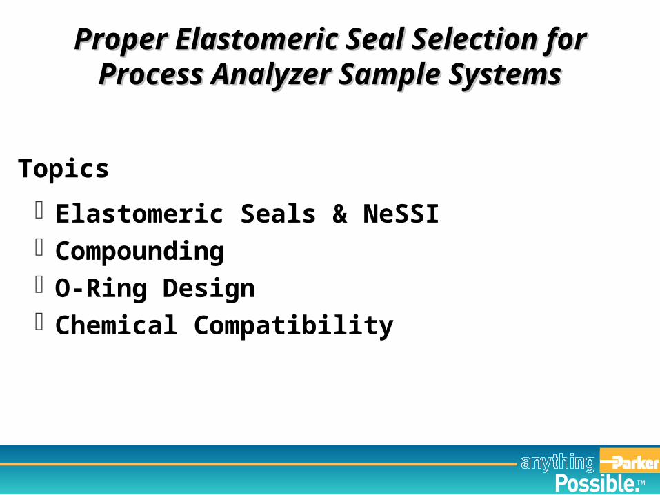
No Matter Which System...
Elastomeric Seals & NeSSIElastomeric Seals & NeSSI
TM
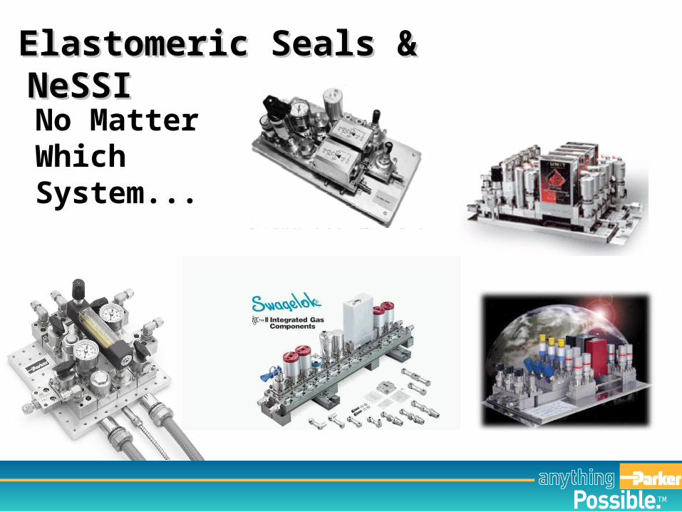
Elastomeric Seals & NeSSIElastomeric Seals & NeSSI
…Elastomeric Seals Are In The Picture!
TM
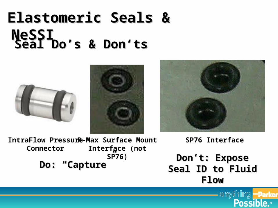
Elastomeric Seals & NeSSIElastomeric Seals & NeSSI
Seal Do’s & Don’tsSeal Do’s & Don’ts
Do: “Capture”Do: “Capture”
IntraFlow Pressure Connector
R-Max Surface Mount Interface (not SP76)
SP76 Interface
Don’t: Expose Seal Don’t: Expose Seal ID to Fluid FlowID to Fluid Flow
TM
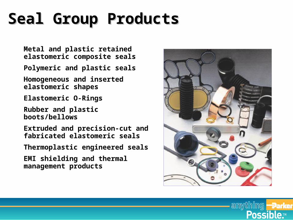
Metal and plastic retained elastomeric composite seals
Polymeric and plastic seals
Homogeneous and inserted elastomeric shapes
Elastomeric O-Rings
Rubber and plastic boots/bellows
Extruded and precision-cut and fabricated elastomeric seals
Thermoplastic engineered seals
EMI shielding and thermal management products
Seal Group ProductsSeal Group Products
TM
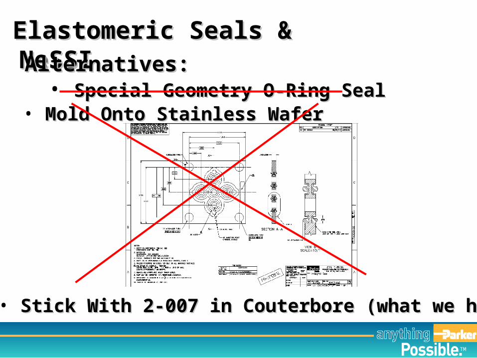
Elastomeric Seals & NeSSIElastomeric Seals & NeSSIAlternatives:Alternatives:
• Special Geometry O-Ring SealSpecial Geometry O-Ring Seal• Mold Onto Stainless WaferMold Onto Stainless Wafer
• Stick With 2-007 in Couterbore (what we have)Stick With 2-007 in Couterbore (what we have)
TM
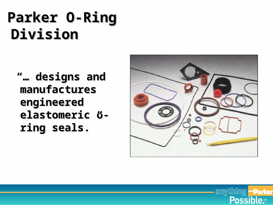
“… “… designs and designs and manufactures manufactures engineered engineered elastomeric o-ring elastomeric o-ring sealsseals.”.”
Parker O-Ring DivisionParker O-Ring Division
TM
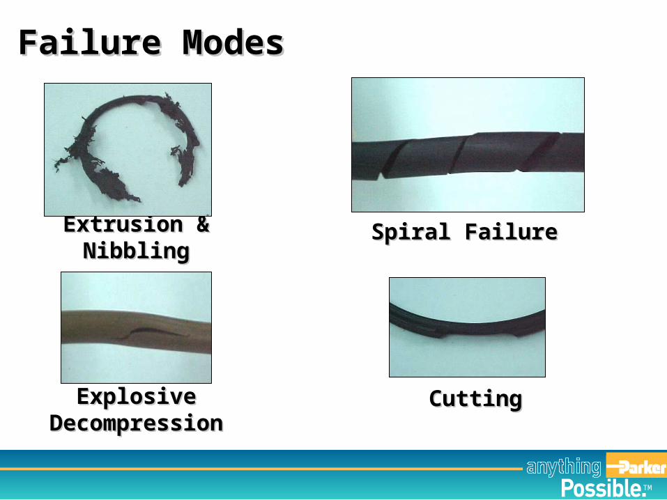
Extrusion & NibblingExtrusion & Nibbling
Failure ModesFailure Modes
Spiral FailureSpiral Failure
Explosive Explosive DecompressionDecompression
CuttingCutting
TM
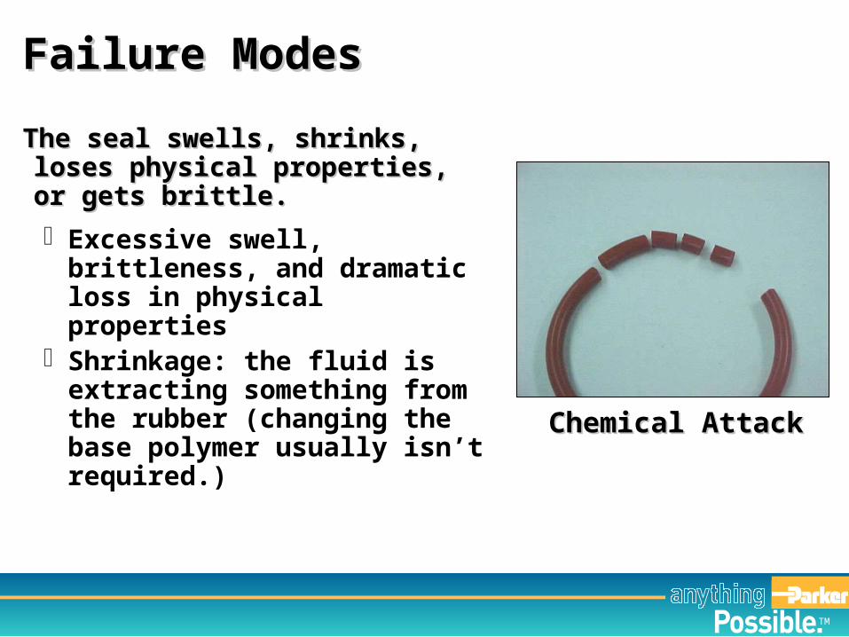
The seal swells, shrinks, loses The seal swells, shrinks, loses physical properties, or gets physical properties, or gets brittle.brittle.
Excessive swell, brittleness, and dramatic loss in physical properties
Shrinkage: the fluid is extracting something from the rubber (changing the base polymer usually isn’t required.)
Failure ModesFailure Modes
Chemical AttackChemical Attack
TM
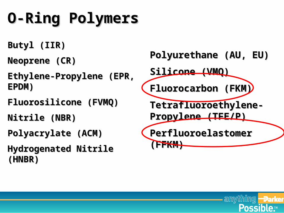
Butyl (IIR)Butyl (IIR)
Neoprene (CR)Neoprene (CR)
Ethylene-Propylene (EPR, Ethylene-Propylene (EPR, EPDM) EPDM)
Fluorosilicone (FVMQ) Fluorosilicone (FVMQ)
Nitrile (NBR)Nitrile (NBR)
Polyacrylate (ACM)Polyacrylate (ACM)
Hydrogenated Nitrile (HNBR)Hydrogenated Nitrile (HNBR)
Polyurethane (AU, EU)Polyurethane (AU, EU)
Silicone (VMQ) Silicone (VMQ)
Fluorocarbon (FKM)Fluorocarbon (FKM)
Tetrafluoroethylene-Tetrafluoroethylene-Propylene (TFE/P)Propylene (TFE/P)
Perfluoroelastomer (FFKM)Perfluoroelastomer (FFKM)
O-Ring PolymersO-Ring Polymers
TM
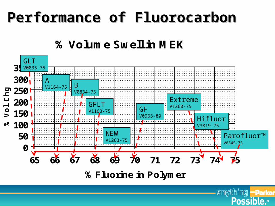
% Volume Swell in MEK
050
100150200250300350
65 66 67 68 69 70 71 72 73 74 75
% Fluorine in Polymer
% V
ol. C
hg
.
GLTV0835-75
AV1164-75 B
V0834-75
GFV0965-80
GFLTV1163-75
ExtremeV1260-75
HifluorV3819-75
ParofluorTM
V8545-75
NEWV1263-75
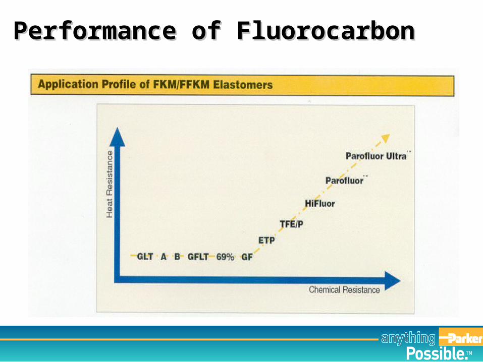
Performance of FluorocarbonPerformance of Fluorocarbon
TM
Performance of FluorocarbonPerformance of Fluorocarbon
TM
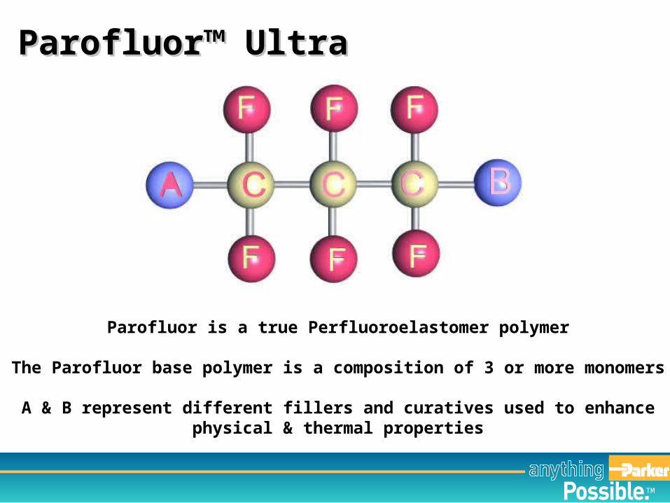
Parofluor is a true Perfluoroelastomer polymer
The Parofluor base polymer is a composition of 3 or more monomers
A & B represent different fillers and curatives used to enhancephysical & thermal properties
Parofluor™ UltraParofluor™ Ultra
TM
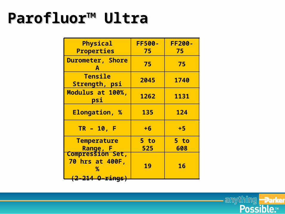
to 550to 6005 to 4465 to 6085 to 525Temperature Range,
F
3525251619Compression Set, 70
hrs at 400F, %
(2-214 O-rings)
--+5+5+6TR – 10, F
125150140124135Elongation, %
18001050115011311262Modulus at 100%, psi
27002450175017402045Tensile Strength, psi
8075757575Durometer, Shore A
Kalrez 1050
Kalrez 4079
Chemraz 505
FF200-75 FF500-75Physical Properties
Parofluor™ UltraParofluor™ Ultra
TM
Parofluor™ UltraParofluor™ Ultra
TM
Base polymer determines chemical resistance, rough Base polymer determines chemical resistance, rough temperature limits, and rebound resiliencetemperature limits, and rebound resilience
In some materials, the high and low temp limits can be modified by other compounding ingredients.
Provides “baseline” for abrasion resistance, Provides “baseline” for abrasion resistance, compression set resistance, permeabilitycompression set resistance, permeability
These can (and almost always are) modified – up or down – by other compounding ingredients.
Compounding: Polymer SelectionCompounding: Polymer Selection
TM
Polymer chains must be cross-linked to achieve resilience Polymer chains must be cross-linked to achieve resilience and elasticity.and elasticity.
Sulfur Organic Peroxides Bisphenol Others: specialty materials have special cure chemistry
Compounding: Cure SystemsCompounding: Cure Systems
TM
Reinforcing agents add mechanical strength and resistance Reinforcing agents add mechanical strength and resistance to abrasion & permeationto abrasion & permeation
Carbon black: standard for black compounds Silica: standard for non-black compounds
Fillers lower the cost of a compound but reduce Fillers lower the cost of a compound but reduce compression set resistance and elongationcompression set resistance and elongation
Compounding: FillersCompounding: Fillers
TM
Oils and / or polymers to lower the low temp limits and Oils and / or polymers to lower the low temp limits and make the material flow better make the material flow better
Reduce resistance to compression set In “generic” materials, they are used to offset the
hardening influence of high levels of filler Can extract into process fluids, resulting in seal
shrinkage & hardening
Compounding: PlasticizersCompounding: Plasticizers
TM
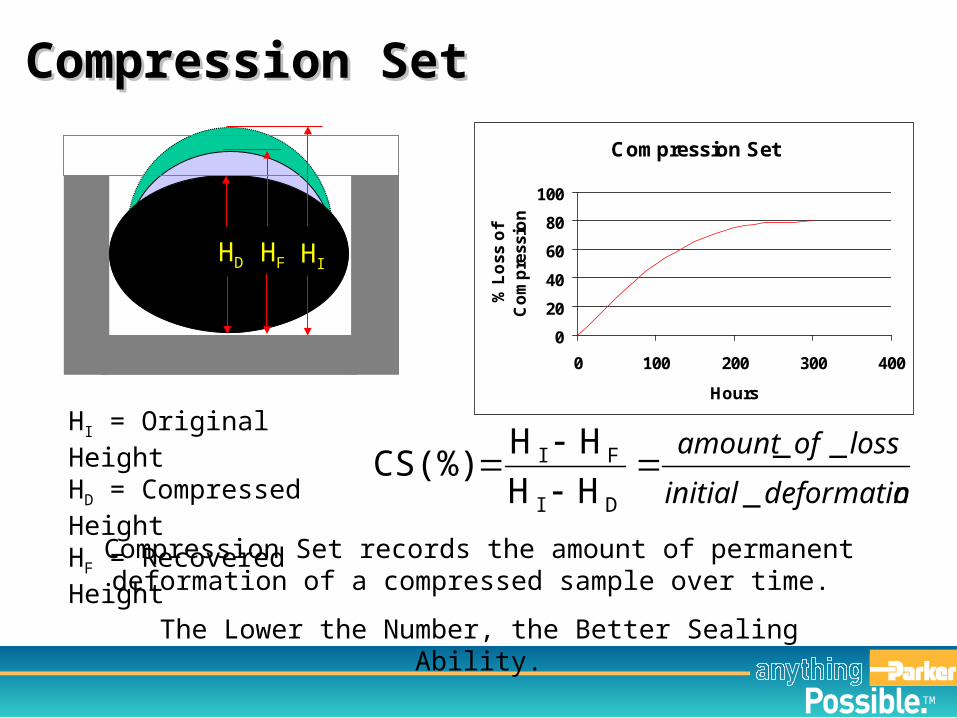
ndeformatioinitial
lossofamount
_
__
DI
FI
HH
HHCS(%)
HI = Original HeightHD = Compressed HeightHF = Recovered Height
HIHD HF
Compression Set records the amount of permanent deformation of a compressed sample over time.
The Lower the Number, the Better Sealing Ability.
Compression Set
0
20
40
60
80
100
0 100 200 300 400
Hours
% L
oss
of
Co
mp
ress
ion
Compression SetCompression Set
TM
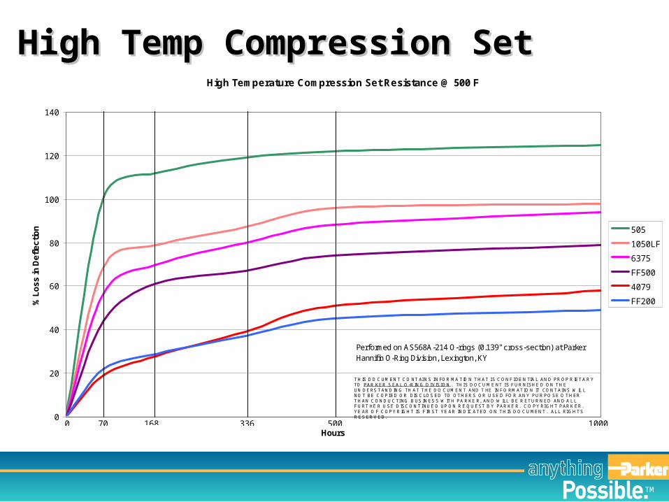
High Temperature Compression Set Resistance @ 500 F
0
20
40
60
80
100
120
140
Hours
% L
os
s in
De
fle
cti
on 505
1050LF
6375
FF500
4079
FF200
70 500336168 1000 0
Performed on AS568A-214 O-rings (0.139" cross-section) at Parker Hannifin O-Ring Division, Lexington, KY
T H IS D O C UM EN T C O NT AI N S I N FOR MA T IO N T H AT I S C ON F I DE N TIA L AN D PR OP R IET A R YTO PAR KER S EA L O-R IN G D I VISI ON . TH I S D OC U M E NT I S F U R NI SH E D ON T H EUN D ERS T AN D IN G TH AT T H E D O C UM EN T AND T HE IN F O RM ATIO N IT CON T AI NS W IL LNO T BE C OPI ED OR DIS C LOS ED TO OT H ER S OR U SE D FO R AN Y PU R PO SE O T H ERT H AN C ON D U C TI NG B US IN ES S W IT H PA R KE R, AN D W ILL B E R ET U R N ED AN D A L LF U RT HE R U SE D ISC ON T I NU E D UP ON R E QU EST B Y PAR KE R. C O PY RI GH T PAR K ER.YE AR O F C OPY R IGH T IS F IR ST YE AR IN D IC AT ED ON T H IS D O C U MEN T . AL L RI GH T SR ES ER V ED.
High Temp Compression SetHigh Temp Compression Set
TM
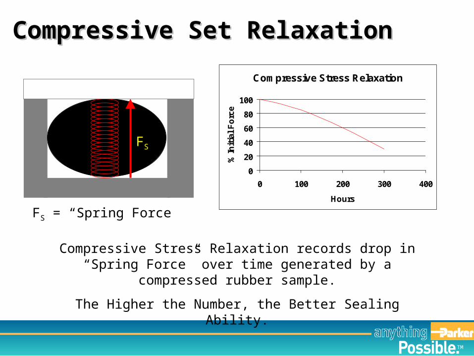
FS = “Spring Force”
FS
Compressive Stress Relaxation records drop in “Spring Force” over time generated by a compressed rubber sample.
The Higher the Number, the Better Sealing Ability.
Compressive Stress Relaxation
0
20
40
60
80
100
0 100 200 300 400
Hours
% I
nit
ial
Fo
rce
Compressive Set RelaxationCompressive Set Relaxation
TM
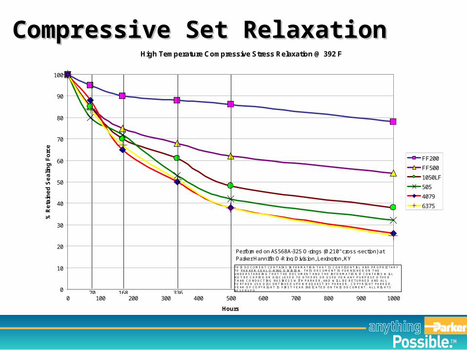
High Temperature Compressive Stress Relaxation @ 392 F
0
10
20
30
40
50
60
70
80
90
100
0 100 200 300 400 500 600 700 800 900 1000
Hours
% R
eta
ine
d S
ea
lin
g F
orc
e
FF200
FF500
1050LF
505
4079
6375
Performed on AS568A-325 O-rings (0.210" cross-section) at Parker Hannifin O-Ring Division, Lexington, KY
70 168 336
T H IS D O C U M E N T CO N T AI N S IN F OR M A T IO N T H A T I S C O N F I DE N T IA L A ND PR O P R I ET A R YT O PA R KE R S E A L O - R I NG D IV IS IO N . T H I S D O C U M E N T I S F U R NI S H E D ON T HEU N D E R S T A N D IN G T H A T T HE D O C U M EN T A N D T H E IN F O R M A T I O N IT C ON T A IN S W IL LN O T B E C O PI E D OR D I SC LOS E D T O O T H E RS OR U S ED F O R A N Y P U R P O S E O T H E RT H AN C O N D U C T IN G BU S IN E S S W IT H P A R K E R , AN D W IL L B E R E T U R N E D A ND AL LF U RT H E R US E D I SC ON T IN U E D U P O N R EQ U ES T BY PA R K E R. C O PY R I G H T PA R K E R.Y E AR O F C O PY R I GH T IS F IR S T Y E A R I ND IC A T E D ON T H IS D O C U M E N T . A L L R IG H T SRE S E R V E D.
Compressive Set RelaxationCompressive Set Relaxation
TM
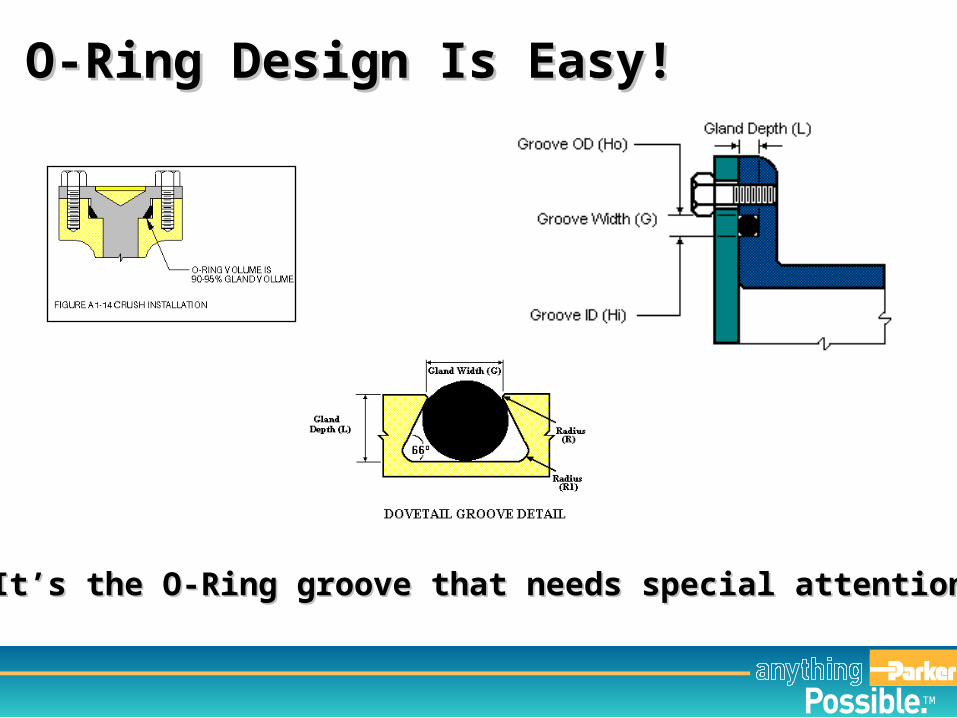
O-Ring Design Is Easy!O-Ring Design Is Easy!
It’s the O-Ring groove that needs special attentionIt’s the O-Ring groove that needs special attention
TM
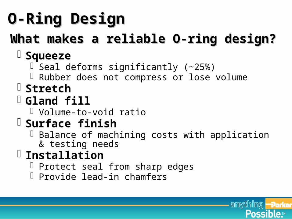
What makes a reliable O-ring design?What makes a reliable O-ring design? Squeeze
Seal deforms significantly (~25%) Rubber does not compress or lose volume
Stretch Gland fill
Volume-to-void ratio Surface finish
Balance of machining costs with application & testing needs
Installation Protect seal from sharp edges Provide lead-in chamfers
O-Ring Design O-Ring Design
TM
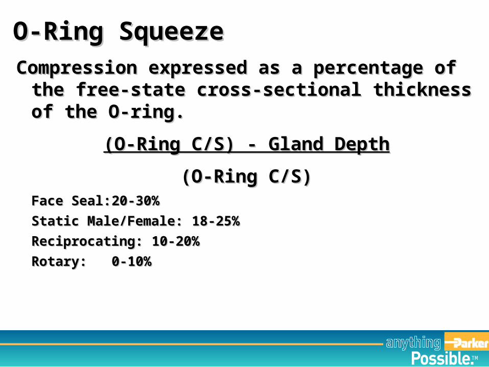
Compression expressed as a percentage of the Compression expressed as a percentage of the free-state cross-sectional thickness of the O-free-state cross-sectional thickness of the O-ring.ring.
(O-Ring C/S) - Gland Depth(O-Ring C/S) - Gland Depth
(O-Ring C/S)(O-Ring C/S)Face Seal:Face Seal: 20-30%20-30%
Static Male/Female:Static Male/Female: 18-25%18-25%
Reciprocating:Reciprocating: 10-20%10-20%
Rotary:Rotary: 0-10%0-10%
O-Ring SqueezeO-Ring Squeeze
TM
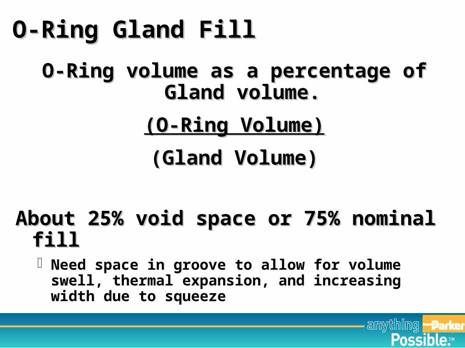
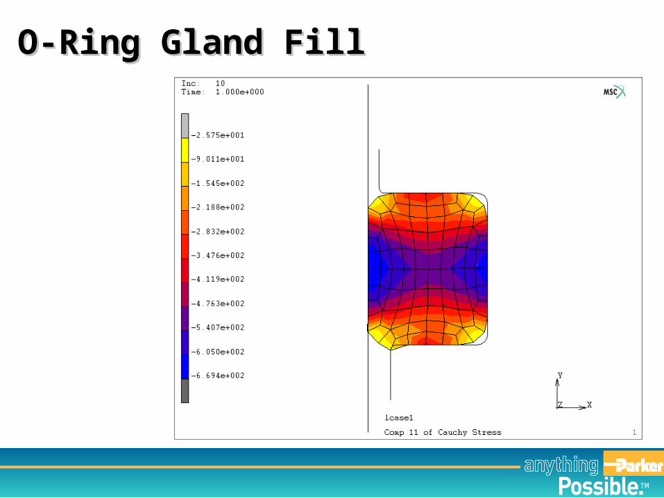
O-Ring volume as a percentage of Gland O-Ring volume as a percentage of Gland volume.volume.
(O-Ring Volume)(O-Ring Volume)
(Gland Volume)(Gland Volume)
About 25% void space or 75% nominal fillAbout 25% void space or 75% nominal fill Need space in groove to allow for volume swell,
thermal expansion, and increasing width due to squeeze
O-Ring Gland FillO-Ring Gland Fill
TM
O-Ring Gland FillO-Ring Gland Fill

TM
www.parkerorings.com www.parofluor.com
Website ResourcesWebsite Resources
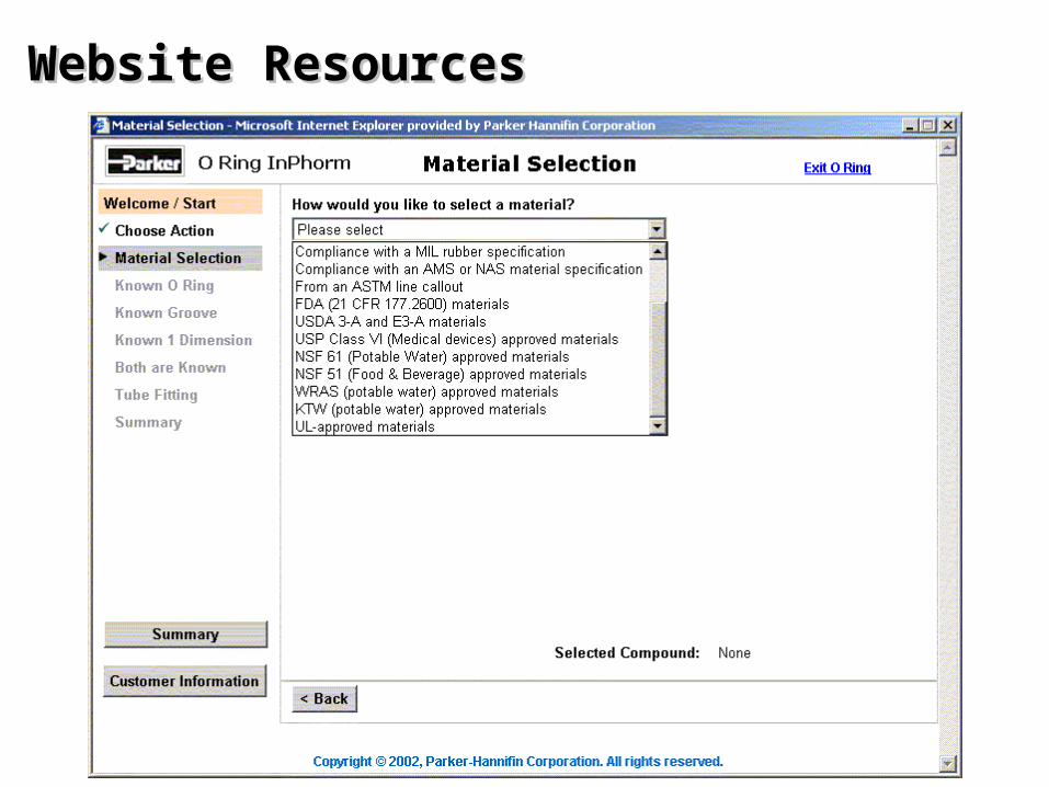
Website ResourcesWebsite Resources
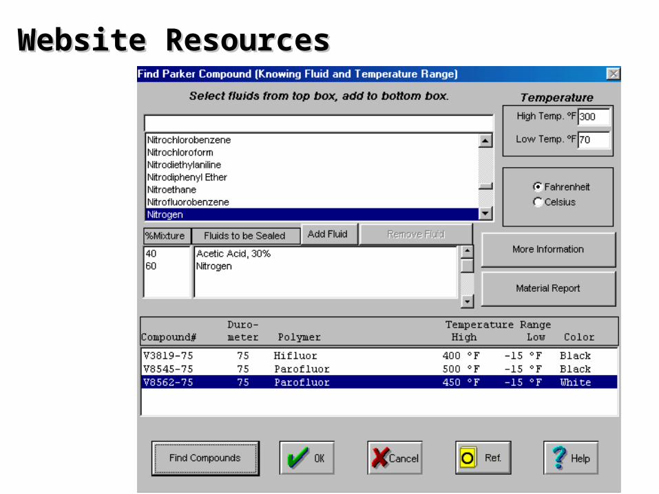
Website ResourcesWebsite Resources
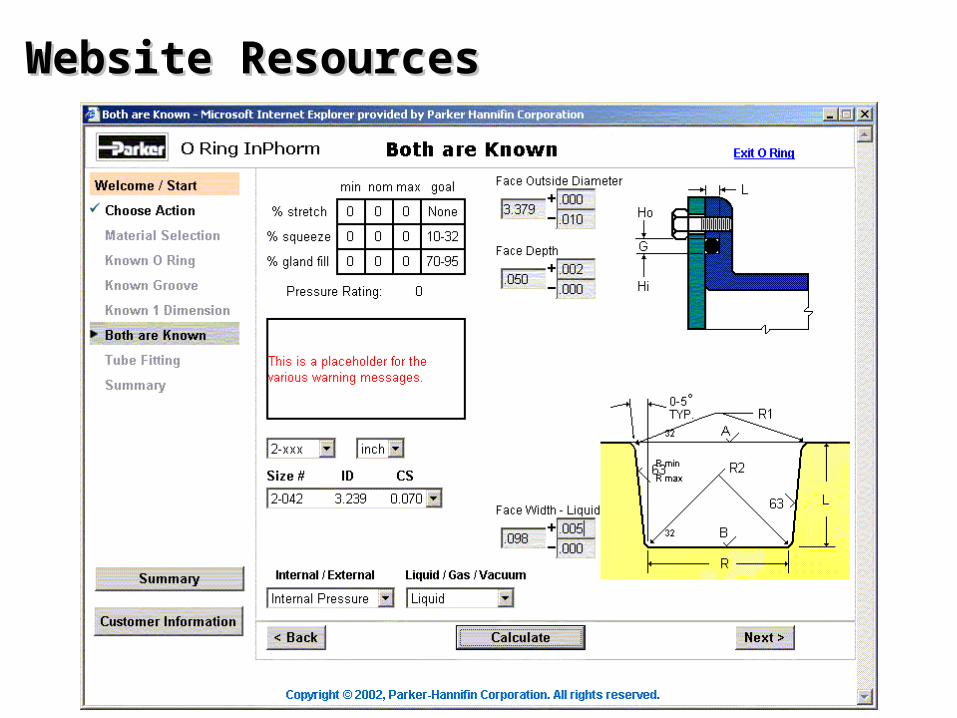
Website ResourcesWebsite Resources

TM
AcknowledgementsAcknowledgements
Dan Ewing, Seal Application
Engineering Manager
Natalie Hicks, Seal Application
Engineering Manager

TM
Patent PendingParker IntraFlowIntraFlow™™
Thank You!Thank You!