Embed Size (px)
Citation preview

INSTALLATION MANUAL
45-67
8-1112-15
16
Installation TipsThemostat Quick ReferenceSubbase InstallationWiring
Technician Setup MenuMounting and Battery Installation
Features & Speci�cations
23
Thermostat Applications Guide
Table of Contents Page
Description
Gas or Oil Heat
Electric Furnace
Heat Pump (No Aux. or Emergency Heat)
Heat Pump (with Aux. or Emergency Heat)
Multi-stage Systems
Heat Only Systems
Cool Only Systems
Millivolt
Yes
Yes
Yes
Yes
Yes
Yes
Yes
Yes
Battery PowerHardwire (Common Wire)Hardwire (Common Wire) with Battery Backup
Power Type
1
Speci�cations
Rev. 1413
A trained, experienced technician must install this product.
Carefully read these instructions. You could damage this product or cause a hazardous condition if you fail to follow these instructions.
Patents and Trademarks pending.Copyright © 2013. All rights reserved.
Una versión en español de este manual se puede descargar en la
página web de la compañía.
VIVE Comfort1111 S. Glenstone Ave., Suite 2-100Spring�eld, MO 65804
Toll-Free: 1-800-776-1635 Web: www.vivecomfort.comHours of Operation: M-F 9AM - 6PM Eastern
TP-S-855CC O M F O R T
TM
5:23PM
F
Tue
MenuAuto
O�

Installation Tip
Wall Locations
Do not install thermostat in locations:• Close to hot or cold air ducts• That are in direct sunlight• With an outside wall behind the thermostat• In areas that do not require conditioning• Where there are dead spots or drafts (in corners or behind doors)• Where there might be concealed chimneys or pipes
Pick an installation location that is easy for the user to access. The temperature of the location should be representative of the building.
NO
NO NO YES
2
INSTALLATION TIPS
The thermostat should be installed approximately 4 to 5 feet above the �oor. Select an area with average temperature and good air circulation.

3
Getting to know your thermostat
THERMOSTAT QUICK REFERENCE
Getting to know your thermostat
2
Fan Button3
System Button4
Menu Buttons Access Door5
Temperature Setpoint Buttons6
Menu Button7
User Program Buttons8
Glow in the Dark Light Button
6
7
8
1
2
3 4
5
Important:The low battery indicator is displayed when the AA battery power is low. If the user fails to replace the battery within 21 days, the thermostat display will only show the low battery indicator as a final warning before the thermostat becomes inoperable. The batteries are located on the back of the thermostat.
LCD1 Hold is displayed whenthermostat program is permanently overridden.
+1 will appear in thedisplay when secondstage of heat or coolis on. +2 will appearfor third stage of heat.
System operation indicators: The COOL, HEAT or FAN icon will display when the COOL, HEAT or FAN is on.NOTE: The compressor delay feature is active if these icons are flashing. The compressor will not turn on until the 5 minute delay has elapsed.
Days of the week and time
Low Battery Indicator: Replace batteries when this indicator is shown.
Program Menu Options:Shows different optionsduring programming.
Indicates the current room temperature.
Programmable Time Period Icons: This thermostat has 4 programmable time periods per day.
Displays the user selectable setpoint temperature.
Set Point Buttons
Program Buttons
Fan Button
Menu Button
Glow in the Dark Light Button
6
1
2
3
4 5
All our thermostats use the same universal magnetic badge.Visit our website to learn more about our free private label program.
About the Badge
LCD Display
Low Battery Indicator: Replace batteries when this indicatoris shown.
1
Removing the private label badge
Gently slide a screwdriver into the bottom edge of the badge. Gently turn the screwdriver counter clockwise. The badge is held on by a magnet. The badge should pry o� easily. Do not use force. Magnet in door
Use the bevel on lower ridge
Getting to know your thermostatIndicates the current room temperature.
Displays the user selectable setpoint temperature.
Hold is displayed when thermostat program is permanently overridden.
Days of the week and time
System Operation Indicators: If these or the Fan indicator are �ashing, it means that they are in a delay of some type (Compressor Delay, Cooling Fan Delay, Staging Delay).
Program Menu Options:Show di�erent options during programming.
Programmable Time Periods
Residential: uses 4 time periods- WAKE, RETURN, LEAVE and SLEEP. Commercial: uses 2 or 4 time periods that appear in the text �eld - Occupied and Unoccupied.
7
10
2
3
4-6
7
9
8
System Button
Button/Battery Access Door
88:88AMPM
8.8CF
S e t A t
8.8H O L DHEAT ONCOOL ON
+1+2
Wake ReturnLeave Sleep
SunMonTueWedThurFriSat
TechSetupPrev
SetHoldSchedNext
SetHoldRunSched
Menu Done
IAQOnAuto
Em.HeatAutoOn
Cool
The low battery indicator is displayed when the AA battery power is low. If the user fails to replace the battery within 21 days, the screen will only show the low battery indicator but maintain all functionality. If the user fails to replace the batteries after an additional 21 days (days 22-42 since �rst “low battery” display) the set points will change to 55˚F(Heating) and 85˚F(Cooling). If the user adjusts these setpoints away from these it will hold for 4 hours then return to either 55˚F or 85˚F. After day 42 the batteries must be replaced immediately to avoid freezing or overheating because the thermostat will shut the unit o� until the battery is changed.
Important
8 9
11
5:23PM
F
Tue
MenuAuto
O�
10
Battery Cover11
Staging Indicators +1 will apear in thedisplay when secondstage of heat or cool is on.+2 will appear for thirdstage of heat.

UP
All of our thermostats are mercury free. However, if the product you are replacing contains mercury, dispose of it properly. Your local waste management authority can give you instructions on recycling and proper disposal.
Caution:Electrical Hazard
Failure to disconnect the power before beginning to install this product can cause electric shock or equipment damage.
CautionMercury Notice:
Vertical Mount
Horizontal Mount
Vertical Mount
Horizontal Mount
4
SUBBASE INSTALLATION
Prior to installing subbase place non-�ammable insulation into wall opening to prevent drafts.
Installation Tip
For vertical mount put one screw on top and one screw on bottom.
For horizontal mount put one screw left and one screw right.
RH
RC
4
3
2
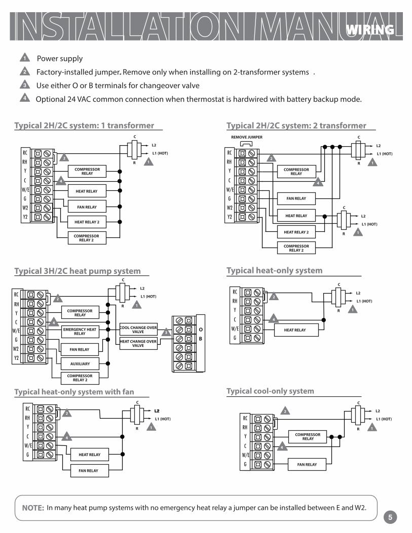
1 Power supply
Factory-installed jumper. Remove only when installing on 2-transformer systems
Use either O or B terminals for changeover valve
Optional 24 VAC common connection when thermostat is hardwired with battery backup mode.
5NOTE: In many heat pump systems with no emergency heat relay a jumper can be installed between E and W2.
WIRING
4
21
COMPRESSOR RELAY
FAN RELAY
HEAT RELAY
C
R
L2
L1 (HOT)
Typical 2H/2C system: 1 transformer Typical 2H/2C system: 2 transformer
COMPRESSOR RELAY
FAN RELAY
HEAT RELAY
4
21
C
R
L2
L1 (HOT)
C
R
L2
L1 (HOT)
REMOVE JUMPER
Typical heat-only system
HEAT RELAY
4
2
1
C
R
L2
L1 (HOT)
FAN RELAY
4
2
1
C
R
L2
L1 (HOT)
COMPRESSOR RELAY
Typical cool-only systemTypical heat-only system with fan
FAN RELAY
4
2
1
C
R
L2
L1 (HOT)
HEAT RELAY
Typical 3H/2C heat pump system
FAN RELAY
1
C
R
L2
L1 (HOT)
COMPRESSOR RELAY
COOL CHANGE OVER VALVE
4
O
B
COMPRESSOR RELAY 2
HEAT RELAY 2
COMPRESSOR RELAY 2
HEAT RELAY 2
HEAT CHANGE OVER VALVE
COMPRESSOR RELAY 2
AUXILIARY
2
3EMERGENCY HEAT
RELAY
1

6
Terminal DesignationsThis thermostat is shipped from the factory to operate a conventional heating and cooling system. The S-855C series may also be con�gured for a heat pump system. See the “heat pump” con�guration step on page 10 of this manual to con�gure the thermostat for heat pump applications.
Wiring Tip
Replacement Thermostat Wiring
1.
2.
3.
If you are replacing a thermostat, make note of the terminal connections on the thermo-stat that is being replaced. In some cases the wiring connections will not be color-coded. For example, the green wire may not be connected to the G terminal.
Loosen the terminal block screws. Insert wires then retighten terminal block screws.
Place non�ammable insulation into wall opening to prevent drafts.
Warning All components of the control system and the thermostat installation must conform to Class II circuits per the NEC Code.
Wire speci�cationsUse shielded or non-shielded 18-22 gauge thermostat wire.
Terminal 2 Heat 2 Cool Conventional System
2 Heat 2 Cool Heat Pump System
3 Heat 2 Cool Heat Pump System
RC
RH
C
B
O
G
W/E
Y
Y2
W2
Transformer Power(cooling)
Transformer Power(heating)
Transformer common
Energized in heating
Energized in cooling
Fan relay
First stage of heat
First stage of cool
Second stage of cool
Second stage of heat
Transformer Power(cooling)
Transformer Power(heating)
Transformer common
Heat pump changeover valveenergized in heating
Heat pump changeover valveenergized in cooling
Fan relay
First stage of emergency heat
First stage of heat & cool
Second stage of cool
Auxiliary heat relay,second stage of heat
Auxiliary heat relay,thirdstage of heat
Second stage of cool & second stage of heat
First stage of heat & cool
Transformer Power(cooling)
Transformer Power(heating)
Transformer common
Heat pump changeover valveenergized in heating
Heat pump changeover valveenergized in cooling
Fan relay
C terminalThe C (common wire) terminal does not have to be connected when the thermostat is powered by batteries.
Note:In many heat pump systems with no emergency heat relay, a jumper can be installed between E and W2 to turn thermostat into a single stage control.
WIRING
First stage of emergency heat

Mount Thermostat
Align the 4 tabs on the subbase with corresponding slots on the back of the thermostat, then push gently until the thermostat snaps in place.
7
MOUNT THERMOSTAT & BATTERY INSTALLATION
Battery Installation
To release battery coverpress finger bevel on the left side and lift the cover to access batteries.
Simple operating instructions are found on the back of the battery door.
Battery installation is recommended even if thermostat is hardwired (C terminal connected). When thermostat is hardwired and batteries are installed, the thermostat will activate a compressor delay of 5 minutes when the thermostat detects a power outage from the hardwired power supply.
Important: High quality alkaline batteries are recommended. Rechargeable batteries or low quality batteries do not guarantee a 1-year life span.
Refer to your Operating Manualfor programming and operation instructions A copy can bedownloaded at www.pro1iaq.com
Replace AA Batteries when low battery indicator shows in display.
Select Heat, Off, or Cool as needed. Select Fan On for continuous operation or Auto to cycle fan with system.
Note: To insure a solid fit between the thermostat and the subbase:
Mount subbase to a flat wall
Use screws provided
Drywall anchors should be flush with the wall
Wires should be pushed into the wall
1.
2.
3.
4.
5:23PM
F
Tue
MenuAuto
O�

Filter Change
ReminderThis feature will �ash “FILT” in the display after the elapsed run time to remind the user to change the �lter. A setting of “OFF” will disable this feature.
You can adjust the �lter change reminder from “OFF” to 2000 hours of runtime in 50 hour increments.
OFF
LCD Will Show
Adjustment Options
This feature allows the installer to change the calibration of the room temperature display. For example, if the thermostat reads 70° and you would like it to read 72° then select +2.
RoomTemperature Calibration
You can adjust the room temperature display to read -4°F to +4°F above or below the factory calibrated reading.
0 ºF
Minimum Compressor On
TimeThis feature allows the installer to select the minimum run time for the compressor. For example, a setting of 4 will force the compressor to run for at least 4 minutes every time the compressor turns on, regardless of the room temperature.
You can select the minimum compressor run time from “OFF”, “3”, “4”, or “5” minutes. If 3, 4, or 5 is selected, the compressor will run for at least the selected time before turning o�.
OFF
Compressor Short Cycle
Delay
Tech Setup Steps
The compressor short cycle delay protects the compressor from “short cycling”. This feature will not allow the compressor to be turned on for 5 minutes after it was last turned o�.
Selecting “ON” will not allow the compressor to be turned on for 5 minutes after the last time the compressor was on. Select “OFF” to remove this delay.
ON
Cooling Swing
The swing setting often called “cycle rate”, “di�erential” or “anticipation” is adjustable. A smaller swing setting will cause more frequent cycles and a larger swing setting will cause fewer cycles.
The heating swing setting is adjustable from 0.2°F to 2°F. For example: A swing setting of 0.5°F will turn the heating on at approximately 0.5°F below the setpoint and turn the heating o� at approximately 0.5°F above the setpoint.
The cooling swing setting is adjustable form 0.2°F to 2°F. For example: A swing setting of 0.5°F will turn the cooling on at approximately 0.5°F above the setpoint and turn the cooling o� at approximately 0.5°F below the setpoint.
0.5 ºF 0.4 ºF
Heating Swing
The swing setting often called “cycle rate”, “di�erential” or “anticipation” is adjustable. A smaller swing setting will cause more frequent cycles and a larger swing setting will cause fewer cycles.
TECH SETUPSTEPS CONTINUED
ON THE NEXT PAGE
KeypadLockout
Keypad lockout allows you to con�gure the thermostat so that none or some of the keys do not function.
PA = partial keypad lockout, which locks all the keys except the or keys.
FU = Full keypad lockout, which locks out all the keys.
Note: keypad lockout instructions are below.
PA
Technician Setup Menu
This thermostat has a technician setup menu for easy installer con�guration. To setup the thermostat for your particular application:
1.
2.
8
Factory Default Setting
Con�gure the installer options as desired, using the table below.
Use the or keys to change settings and the NEXTor PREV key to move from one step to another. Note: Only press DONE key when you want to exit the Technician Setup options.
Press DONE key to exit.
3.
Press MENU button.
TECHNICIAN SETUP MENU
Press and hold TECH SETUPbutton for 3 seconds. This 3 second delay is designed so that homeowners do not accidentally access the installer settings.
4.
Note: The function of activating your Keypad Lockout choice takes place after you have exited Tech Setup. If you do not perform this activation procedure, all keys will function freely. To lock the keypad hold down the and keys for 3 seconds.You will see a lock in the display. To unlock the keypad hold down the and keys for 3 seconds.

TECH SETUPSTEPS CONTINUED
ON THE NEXT PAGE
9
Heating Temperature
Setpoint LimitThis feature allows you to set a maximum heat setpoint value. The setpoint tempera-ture cannot be raised above this value.
Use the or key to select the maximum heat setpoint.
Range 44ºF - 90ºF
90ºF
LCD Will Show
Adjustment Options
Tech Setup Steps (Continued from the previous page)
Factory Default Setting
Cooling Temperature
Setpoint Limit This feature allows you to set a minimum cool setpoint value. The setpoint tempera-ture cannot be lowered below this value.
Use the or key to select the minimum cool setpoint.
Range 44ºF - 90ºF
44ºF
ºF or ºC
This feature allows you to display temperatures in either Fahrenheit or Celsius.
ºF for Fahrenheit
ºC for Celsius
ºF
Fan Operation
GAS
Select GAS for systems that control the fan during a call for heat.
Select ELEC to have the thermostat control the fan during a call for heat.
GAS
or
ELEC
TECHNICIAN SETUP MENU
12 or 24 Hour Clock
Use the or key to select 12 or 24 hour clock.
You can select either a 12 or 24 hour clock setting.
12 Hour Clock
Morning Recovery
This feature will start heating early to bringthe building temperature to its programmedsetpoint by the beginning of the time period - (WAKE, OCCUPIED).
Use the or key to turn on or o�.
ON
Program Options
You can con�gure this thermostat to have a 7 day program, a 5+1+1 program or nonprogrammable.
Use the or key to select 7d for 7 day, 5d for 5+1+1, or 0d for nonprogrammable.
5d
Time Periods
4
You can con�gure thisthermostat to have 2or 4 programmabletime periods per day.4 time periods areWake, Leave, Return& Sleep.2C time periodsare occupied andunoccupied.4C time periods areOccupied 1, Unoccupied 1Occupied 2, and Unoccupied 2.
Use the orkey to select 4, 2c, or 4ctime periods per day.
The second stage will turn on at 2x the swing setting. The second stage will turn off when 1x the swing is reached. For example, if the swing setting is .5 degrees for heating and the thermostat is set at 70ºF, the first stage will turn on at approximately 69.5ºF. The second stage will turn on at 69.0ºF. The second stage will turn off at 69.5ºF and the first will turn off at 70.5ºF. If third stage is used, it will turn on at 3x the swing and turn off at approximately 2x the swing.
Swing Setting Tip

10
TECHNICIAN SETUP MENU
Note: If contractor Call Number is selected ON, your phone number will show inthe display if there has been a continuous call for heating or cooling for 24 hours or if the light button is held down for 3 seconds. To remove the phone number from the display, hold the light button down for 3 seconds.
Adjustment Options
Factory Default Settings
Tech Setup Steps (Continued from the previous page)
Contractor Call Number
Beep Heat Pump
LCD Will Show
System Set
Gas Auxiliaryfor Heat Pump
ON
When any key is pressed an audible beep will sound.
You can choose ON or OFF
If ON is selected the beep will sound.
If OFF is selected, there is no sound.
OFF
When turned on the thermostat will operate a heat pump.
1. EM.Heat will show as an option in the system switch.
2. Y will be �rst stage of heat & cool, W/E will be emergency heat relay & W2 will be auxiliary heat relay.
OFF con�gures the thermostat for non heat pump systems.
ON con�gures the thermostat for heat pump systems.
Heat - O� - Cool
You can con�gure the system switch for the particular application:
Heat - O� - Cool,Heat - O�, Cool - O�, Heat - O� - Cool-Auto
Note: EM. Heat will show if in heat pump mode.
Use the or key until the desired application is �ashing.
OFF
Allows you to put your phone number in the display.
You can choose ON or OFF
Use the or key to select the desired number and the FAN or SYSTEM key to move from one character to another. See note below on operation.
If selected ON , you will see the input screen after pressing next step.
OFF
This option will turn the heat pump o� 45 seconds after the auxiliary heat relay turns on.
For 2 heat applications, the �rst stage will turn o� 45 seconds after the auxiliary stage turns on.
For 3 heat applications, the �rst and second stage will turn o� 45 seconds after the auxiliary stage turns on.
For heat pump systems that are “dual fuel” (use a gas furnace for auxiliary stage heat) you can turn this feature on to turn o� the heat pump when the auxiliary stage of heating has been called for.
OFF
DisplayLight
The display light can be con�gured to stay on all the time or come on when any key is pressed.
NOTE:HARDWIRE ONLYKeeping the display light continually “ON” will greatly reduce battery life.
OFF con�gures display light to come on when the light key or any key on screen is pressed.
ON con�gures the display light to stay on.
TECH SETUPSTEPS CONTINUEDON THE NEXT PAGE
Pre OccupancyFan
The pre occupancyfan settings willenergize the fanbefore the occupiedtime to provideventilation prior toscheduledoccupancy.
This feature only shows if techniciansetup step for timeperiods is set to 2C or 4C.
You can select thepre occupancy fan from OFF, 1, 2, or3 hours.
If 1, 2, or 3 is selected, the fan will turn on that many hours prior to the scheduled occupied time period.
OFF
PRE OCCUPY FAN
You can con�gure the thermostat to operate a 3 stage heat pump system.
2H 2C = 2 heat, 2 cool3H 2C = 3 heat, 2 cool
This feature only shows if Technician Setup Step for HEAT PUMP is set to ON .
Use the or key to change between 2 heat and 3 heat.
2 heat will use Y1 as �rst stage and W2 as auxiliary.
3 heat will use Y1 as �rst stage, Y2 as second stage and W2 as auxiliary.
Stages of Heat
2 Stages
Use the or key to turn on or o�.

TECHNICIAN SETUP MENU
11
OFF 1 OFF
Adjustment Options
LCD Will Show
Tech Setup Steps (Continued from the previous page)
OFF OFF
Factory Default Settings
Cooling FanDelay
The cooling fan delay setting will delay the fan from coming on in coolmode and keeprunning after thecompressor shuts o� for a short time to save energy in some systems.
You can select the Cooling Fan Delayfrom OFF, 15, 30, 60 or 90 Seconds.
COOL FAN DL
Satisfy Setpoint
This feature allows the thermostat to keep multiple stages of heat or cool energized until setpoint is satis�ed.
Use the or key to turn on or o�.
Staging Delay
This feature allows a delay to occur when a second and third stage is needed. This allows the previous stage extra time to satisfy setpoint.
Use the or key to select YES, 5, 10, 15, 30, 45, 60, or 90 minutes.
Humidity Pad Reminder
This will remind the user to change the humidity pad.
Use the or key to select OFF, 600, 1000, 1500, 2000. These represent hours of heat operation.
UV Lamp Reminder
Will remind the user to change the UV light bulb.
Use the or key to select OFF, 1YEAR, 2YEAR.
IAQ Cell Reminder
Will remind the user to change the PHI Cell after 25,000 hrs.
Use the or key to select OFF, 250. (Stands for 25000 hours)
IAQ Mode Cycle
This feature will con�gure the fan to run a selected number of cycles“per hour”.
Note: This mode can be enabled or disabled at anytime during normal operation, by selecting IAQ mode with the fan key.
Select OFF, 1,2,3 or 4with the or keys.
This sets the number of cycles per hour that the IAQ fan mode will operate.
IAQ MODE CYCLE
OFF
IAQ MODE M INUT
IAQ Mode Minutes
This allows you to select the minimum number of minutes that the fan will run “Per Cycle “. The thermostat will keep track of fan run time from normal Heat and Cool operation. If additional fan runtime is needed, the thermostat will run the fan to satisfy the IAQ mode minutes.
Select 1, 5, 10 ,15 ,20 ,30 or 45 minutes.
When IAQ fan mode is enabled, it will ensure the fan runs at least the selected number of minutes per IAQ mode cycle.
1
OFF OFF
This Programmable/Selectable mode will operate the fan 1-4 cycles per hour, 1-45 minutes per cycle. Once programmed in Tech Setup, to enable this mode select ‘IAQ’ with the Fan Key. Or youcan disable the mode by selecting ‘ON’ or ‘AUTO’ with the Fan Key.
A Note about IAQ Mode:

12
PROGRAMMING
Set Time
Programming
Weekday 6 a.m. 70° F (21° C) 75° F (24° C)
8 a.m. 62° F (17° C) 83° F (28° C)
6 p.m. 70° F (21° C) 75° F (24° C)
10 p.m. 62° F (17° C) 78° F (26° C)
Factory Default Program
Saturday 8 a.m. 70° F (21° C) 75° F (24° C)
10 a.m. 62° F (17° C) 83° F (28° C)
6 p.m. 70° F (21° C) 75° F (24° C)
11 p.m. 62° F (17° C) 78° F (26° C)
Sunday
Day of the Week
Setpoint Temperature (Cool)
Setpoint Temperature (Heat)TimeEvents
All our programmable thermostats are shipped with an energy saving pre-program. You can customize this default program by following the Set Program Schedule.
Follow the steps below to set the day of the week and current time:
Press MENU
Press SET TIME
Day of the week will be flashing. Use the or key to select the current day of the week.
Press NEXT
The current hour is flashing. Use the or key to select the current hour. When using 12-hour time, make sure the correct a.m. or p.m. choice is selected.
Press NEXT
Minutes are now flashing. Use the or key to select current minutes.
Press DONE when completed
1.
2.
3.
4.
5.
6.
7.
8.
Your thermostat can be programmed to have each day of the week programmed uniquely (7 days), all theweekdays the same, a seperate program for Saturday, and a seperate program for Sunday (5+1+1), or non-programmable.There are three time period options for each program. 1. Residential ‘4’ (WAKE, LEAVE, RETURN, SLEEP) 2. ‘2C’ Commercial (OCCUPIED, UNOCCUPIED) 3. ‘4C’ Commercial (OCCUPIED 1, UNOCCUPIED 1, OCCUPIED 2, UNOCCUPIED 2) . This thermostat has aprogrammable fan feature, which allows you to run the fan continuously during any time period.
Wake / OCC 1
Leave / UNOCC 1
Return / OCC 2
Sleep / UNOCC 2
Wake / OCC 1
Leave / UNOCC 1
Return / OCC 2
Sleep / UNOCC 2
8 a.m. 70° F (21° C) 75° F (24° C)
10 a.m. 62° F (17° C) 83° F (28° C)
6 p.m. 70° F (21° C) 75° F (24° C)
11 p.m. 62° F (17° C) 78° F (26° C)
Wake / OCC 1
Leave / UNOCC 1
Return / OCC 2
Sleep / UNOCC 2

PROGRAMMING
13
Wake / OCC 1
Leave / UNOCC 1
Return / OCC 2
Sleep / UNOCC 2
Occupied
Unoccupied
Wake / OCC 1
Leave / UNOCC 1
Return / OCC 2
Sleep / UNOCC 2
Occupied
Unoccupied
Wake / OCC 1
Leave / UNOCC 1
Return / OCC 2
Sleep / UNOCC 2
Occupied
Unoccupied
Occupied
Unoccupied
Occupied
Unoccupied
Occupied
Unoccupied

PROGRAMMING
14
Set Program Schedule For Four Time Periods (WAKE, LEAVE, RETURN, SLEEP or OCCUPIED 1, UNOCCUPIED 1, OCCUPIED 2, UNOCCUPIED 2)
Press SET SCHED Note: Monday-Friday is displayed and theWAKE/OCC1 icon is shown. You are now programming the WAKE/OCC1time period for the weekday setting.
Time is �ashing. Use the or key to make your timeselection for the weekday WAKE/OCC1 time period. Note: If you wantthe fan to run continuously during this time period, select ON withthe FAN key. If you want to use IAQ mode during this time period,select IAQ with the fan key.
The setpoint temperature is �ashing. Use the or keyto make your setpoint selection for the weekday WAKE/OCC1 period.
Repeat steps 4 through 7 for weekday LEAVE/UNOCC1 time period,for weekday RETURN/OCC2 time period, and for weekday SLEEP/UNOCC2time period.
Repeat steps 4 through 7 forSaturday WAKE/OCC1 time period,for Saturday LEAVE/UNOCC1 timeperiod, for Saturday RETURN/OCC2time period, and for SaturdaySLEEP/UNOCC2 time period.
Repeat steps 4 through 7 forSunday WAKE/OCC1 time period,for Saturday LEAVE/UNOCC1 timeperiod, for Sunday RETURN/OCC2time period, and for SaturdaySLEEP/UNOCC2 time period.
Note: Monday is displayed and the WAKE/OCC1 icon is shown. You are now programming the WAKE/OCC1 time period for the monday setting.
Time is �ashing. Use the or key to make your time selection for the Monday WAKE/OCC1time period. Note: If you want the fan to run continuously during this time period, select ON with theFAN key. If you want to use IAQ mode during this time period, select IAQ with the fan key.
The setpoint temperature is �ashing. Use the or key to make your setpoint selectionfor the Monday WAKE/OCC1 period.
Repeat steps 4 thru 7 for Monday LEAVE/UNOCC1 time period, for Monday RETURN/OCC2time period, and for Monday SLEEP/UNOCC2 time period.
The programmable fan feature will runthe fan continuously during any timeperiod it is programmed to be on. This is the best way to keep the air circulated and to eliminate hot & cold spots in yourbuilding. If using IAQ Mode, Set fan to IAQ for any time period desired.

PROGRAMMING
15
If you want to use IAQ mode during this time period, select IAQ with the fan key.
Sunday time If you want to use IAQ mode during this time period, select IAQ with the fan key.

FEATURES & SPECIFICATIONS
16
The display range of temperatureThe control range of temperatureLoad ratingDisplay accuracySwing (cycle rate or di�erential)
Power source
Operating ambientOperating humidityDimensions of thermostat
41ºF to 95ºF (5ºC to 35ºC)44ºF to 90ºF (7ºC to 32ºC)1 amp per terminal, 1.5 amp maximum all terminals combined± 1 ºFHeating is adjustable from 0.2ºF to 2.0ºF Cooling is adjustable from 0.2ºF to 2.0ºF 18 to 30 VAC, NEC Class II, 50/60 Hz for hardwire (common wire)Battery power from 2 AA Alkaline batteries32ºF to +105ºF (0º to +41ºC)90% non-condensing maximum4.9 ”W x 4.5”H x 1.0”D
Speci�cations
Temporary and Permanent Hold Feature
Temporary hold: The thermostat will displayHOLD and RUN SCHED on the bottomof your screen when you press the orkey. If you do nothing, the temperature willremain at this setpoint temporarily until the next program period begins. Your programsetpoint will then replace your temporarysetpoint.
Permanent hold: If you press the HOLD key at the bottom of your screen, you will see HOLDappear below the setpoint temperature in the display. The thermostat will now permanentlystay at this setpoint and can be adjustedusing the or keys.
To return to program: Press the RUNSCHED key at the bottom of your screento exit either temporary or permanent hold.
If your installing contractor has configured the thermostat to remind you when the air filter needs changed, you will see FILTdisplay when your air filter needs changed.
will be shown in the display after your system has run long enough to require an air filter change.
Resetting the filter change reminder: When reminder is displayed, you should
change your air filter and reset the reminder by holding down the 3rd button from theleft side of the thermostat for 3 seconds.
This thermostat also has other maintenancereminders (Humidity Pad, UV lamp, and IAQCell), that are reset with the same procedure.
FILT
Filter Change and other Reminders
FILT