Embed Size (px)
Citation preview

1
Instruction Manual
October, 199778-8097-6012-3 Rev A
Dynatel 965DSP-BSubscriber Loop Analyzer
TM

2

3
Welcome to the Instruction Manual for the965DSP-B. ‘DSP’ means ‘Digital SignalProcessor.’ Digital Signal Processing allows the965DSP-B instrument to provide the fast andflexible test functions needed for diagnostictesting. ‘B’ means ‘Basic’. The ‘B’ version doesnot have the TDR function found in the 965DSP.
This document will give you a brief overview ofthe product, a description of the test functions,and some technical hints on how to find commonproblems on telecommunications cables.
This document is not meant to be a substitute fordiagnostic test training. For further informationon complete training, contact 3M TelecomSystems Technical Service at: 800 426 8688.
Table of Contents:
Out of the Box 4Screen 5Keypad 5
Control keys 6Editing 6Function keys 7
Functions:Contrast 9High Voltage 9Voltage 10Current 11Resistance 12Toolbox 13
Self Calibrate 14Load Coils 15Ohms/Distance 16Caller ID 17
Opens 18Tone 21RFL 23ISDN 29dB 31Auto 34
Talk Set 37Care and Maintenance 39Specification 42Warranty Information 43

4
Out of Box
Here’s what you will find when you unpack theshipping box:
965DSP-BCarrying CaseNMH Battery Pack
(inside the 965DSP-B)Spare Battery HolderTest Leads
- Red/Black Pair- Blue/Yellow Pair- Green Lead
Shorting StrapAC/DC AdaptorPower CordInstruction ManualQuick CardWarranty Card
The 965DSP-B comes in the carrying case andshould remain in the case to give extraprotection from shock and the environment.
The 965DSP-B comes with the battery packalready installed. You may need to charge thebattery before using the unit. Please see page 39for information on charging the battery pack.
The Spare Battery Holder holds six “AA”alkaline batteries, and should only be used if thebattery pack is discharged and the AC/DCconverter is not available.
The 965DSP-B comes with 5 test leads. Red,Black and Green are used for most functions.Yellow is used for RFL. The Shorting Strap isonly used in RFL.
The AC/DC adaptor will convert 110 or 220 Vacinto the 12 Vdc used for charging the 965DSP-B. A North American 110 Vac Power Cord isprovided.
Additional information is also found in the965DSP-B help screens. For Technical Service,Warranty or Repair questions call: 800 4268688 or contact your Local 3M Representative.
© Minnesota Mining and Manufacturing3M Telecom Systems Division
6801 River Place Blvd.Austin, Texas 78726-9000 USA

5
Screen
The 965DSP-B screen is a graphical LCD(Liquid Crystal Display) that gives highresolution for viewing text and graphics. Thescreen format is similar to the following formost functions.
Keypad
The 965DSP-B Keypad has twelve yellow andred “Control Keys” and twelve blue “FunctionKeys”.
Test LeadsTest Lead icons are shown on eachmeasurement screen. They always point to thecolor dots on the front label that corresponds tothe real test leads.

6
Control Keys
Use the red and yellow keys to control the actionsand the setup of the 965DSP-B and its functions.The active control keys for each function areshown at the bottom of the corresponding screen.
Use the [Back] key to return to aprevious step in a function.
Use the [Contrast] key to adjust thecontrast or to turn the backlight on or off.
The [Save] key is reserved for futuresoftware enhancements, and is a ‘dash’or ‘minus’ sign when editing numbers.
Use the [On/Off] key to turn the 965DSPon or off.
Use the [Tab] key to select betweendifferent options.
Use the [Setup] key to change the setupof any function.
Use the [Help] key to get help with anyscreen.
Use the [Enter] key to accept changes ormove to the next step in a function.
Use the [Up] and [Down] keys toscroll to different menu options.
Use the following keys when editing numbers:
Use to insert a space to the left of the cursor.
Use to delete the number above the cursor.
Use the [Left] and [Right] keys tomove between different options.
Editing
Use to add a ‘dash’ in a telephone number ora minus sign for levels or temperature.
7
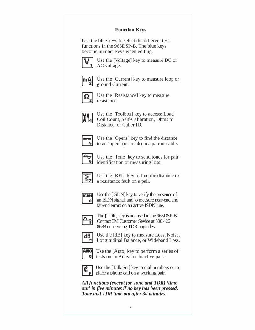
Function Keys
Use the blue keys to select the different testfunctions in the 965DSP-B. The blue keysbecome number keys when editing.
Use the [Voltage] key to measure DC orAC voltage.
Use the [Current] key to measure loop orground Current.
Use the [Resistance] key to measureresistance.
Use the [Toolbox] key to access: LoadCoil Count, Self-Calibration, Ohms toDistance, or Caller ID.
Use the [Opens] key to find the distanceto an ‘open’ (or break) in a pair or cable.
Use the [Tone] key to send tones for pairidentification or measuring loss.
Use the [RFL] key to find the distance toa resistance fault on a pair.
Use the [ISDN] key to verify the presence ofan ISDN signal, and to measure near-end andfar-end errors on an active ISDN line.
The [TDR] key is not used in the 965DSP-B.Contact 3M Customer Sevice at 800 4268688 concerning TDR upgrades.
All functions (except for Tone and TDR) ‘timeout’ in five minutes if no key has been pressed.Tone and TDR time out after 30 minutes.
Use the [dB] key to measure Loss, Noise,Longitudinal Balance, or Wideband Loss.
Use the [Talk Set] key to dial numbers or toplace a phone call on a working pair.
Use the [Auto] key to perform a series oftests on an Active or Inactive pair.

8
Welcome Screen
This is the screen you see when you first turn onthe 965DSP-B. It shows the model name, serialnumber, copyright date, software version, andthe version country.
When the Welcome screen shows, press [Setup]to go to the Setup screen.
Press [Enter] to change the Units ofMeasurements (Distance and Temperature).
Press [Back] to return to the Welcome screen.
Setup

9
Contrast
Press the [Contrast] key to display the contrastscreen. Use the [Up] and [Down] arrow keys toadjust the contrast. Press the [Contrast] keyagain to turn the backlight on or off.
Use the [Up] and [Down] keys to highlighteither Distance or Degrees. Use the [Tab] key toselect the units of measurement.
Use [Enter] to accept the changes and return.Use [Back] to return without making changes.
Units

10
Press the [Tab] key to move to the next test leadconfiguration.
Press the [Enter] key to switch between DC andAC voltage.
Voltage
This function first measures and displays the DCvoltage between the Red and Black test leads.
Press the [Tab] key to move to the next test leadconfiguration.
Press the [Enter] key to switch between AC andDC voltage.

11
This screen indicates that a high current hasbeen detected between the test leads and that the965DSP-B has opened an internal relay toprotect itself from damage. Use standard safetypractices for disconnecting the test leads. Pressthe [Enter] key to start the Current test again.
Current
This function measures the current flowing intothe Red and Black test leads (and a 430 Ohmresistor inside the 965DSP-B). Connect the Redand Black leads to the pair to measure loopcurrent. Connect the Red lead to the voltage sideof the pair and the Black lead to ground tomeasure ground current.
If the Current is greater than 110 mA , you willsee the following ‘Current Warning’ screen:

12
Resistance
This function first measures the resistancebetween the Red and Black test leads.
Press the [Tab] key to move to the next test leadconfiguration.
The “V” in the upper right corner of the screenindicates that the resistance measurementcompensates for C.O. voltage on the line.
Press the [Enter] key to remove the voltagecompensation. Use this test only if you havefirst determined there is no DC voltage on thepair (by using the Voltage function). The non-compensated measurement is slightly faster, butis not as accurate if there is voltage on the line.

13
Toolbox
Use the [Up] and [Down] arrow key to move tothe desired ‘tool’, then press the [Enter] key toaccept the choice.
The Toolbox contains four additional functions:
• Self-Calibrate• Load Coils• Ohms to Distance• Caller ID
Descriptions of these functions are found in thefollowing pages.
The fifth item in the menu (Maintenance) isonly used during 965DSP-B factory service.

14
Self-Calibration
Use this function to calibrate the 965DSP-Banytime the outside temperature changes bymore than 35°F (20°C). Calibrate the 965DSP-Bat the same temperature at which it will be used.
You will see the following screen as soon as youselect Self-Calibration from the Toolbox. Testlead connections (open or shorted) are notimportant during this phase of the calibration.
Short all five leads when prompted, then press[Enter] to continue.
The screen shows “Self-Calibration Complete”when the calibration is done.

15
Load Coils
This function takes about one minute to countup to four load coils on the pair. You will seethe word ‘Counting’ in the display while the testis in progress. You will see the word ’Done’when then test is complete.
Press the [Enter] key at any time if you wish tostop the count earlier. The screen then shows thenumber of load coils counted and the word‘Stopped’ on the screen.
If you are only looking to see if a line has loadcoils or not, you may elect to stop the test afterone load coil has been detected.
After the test is done or was stopped, press the[Enter] key to repeat the load coil count. Pressthe [Back] key to return to the Toolbox menu.
Note that you must have 2000 feet (600 meters)before and after each load coil for the Load Coilfunction to count properly.

16
Ohms/Distance
Use this function to convert between Ohms andDistance based on the temperature and wiregauge entered.
Enter the value of Ohms, then press the [Tab]key to select wire gauges or temperature.
If you select wire gauges, press the [Up] and[Down] keys to select the desired gauge.
If you choose temperature, enter the value of thedesired temperature using the Blue keys.
Press the [Enter] or the [Tab] key when you areready to convert from Ohms to Distance.
Press the [Setup] key to enter distance instead ofOhms. All control keys work the same whenentering distance.

17
Caller ID
This function detects the Caller ID signal senton the pair and displays the calling number, thename of the calling party , the signal level, andthe message status. Certain result boxes may beblank if the information is not available from theCaller ID signal.
Use the [Up] and [Down] arrows to adjust thespeaker volume. Press the [Tab] key foradvanced Caller ID data.
This screen shows advanced information fordiagnosing Caller ID protocol problems.
Press the [Enter] key to return to the previousscreen.

18
Opens
This function shows the distance to an ‘open’(or ‘break’) based on the cable type chosen. TheOpens function is most accurate if other pairs inthe cable are active. If other pairs are not active,you must short at least 30% of the other pairs tothe cable shield.
Press the [Up] or [Down] keys to move to adesired cable type. Press the [Enter] key toaccept the choice and return to the main Opensscreen. Press the [Back] key to return withoutchanging the cable type.
Press the [Tab] key to edit the “Custom” cabletype. Press the [Enter] key to edit the “CalibratedCable” type.
The 965DSP-B will first measure the distance toan open between Red and Black. Press the [Tab]key to move to the next test lead configuration.
Press the [Setup] key to change the Cable Type,or to select Capacitance.

19
Edit Custom
Use this function to change the value of the“Custom Cable” type. You should use CustomCable if you are using a specific type of specialcable on a regular basis.
Press [Enter] to accept the changes and return tothe Opens Setup screen. Press [Back] to returnwithout making changes.
First enter the red to black capacitance/distanceusing the Blue keys. This capacitance issometimes called ‘Mutual’ capacitance.
Then press [Tab] and use the Blue keys to enterthe capacitance/distance for Black to Green.This capacitance is sometimes called the ‘Pair toShield’ or ‘Pair to Ground’ capacitance.

20
Calibrate to Cable
Use this function to measure the capacitance ofa known good pair within a cable of knownlength. This value can be used as a ‘CalibratedCable’ (or ‘reference’) to find the distance to an‘open’ on the same or similar cable.
Connect the Red and Black leads to the pair (tobe used as a reference) and Green to shield.
Press the [Enter] key to accept the results as thenew “Calibrated Cable” and return to the Setupscreen. Press [Back] to return without saving theresults. (if shown) indicates the Ring-Groundcapacitiance differs from Tip-Ground.
Enter the length of the section and press the[Enter] key to measure the capacitance.
The 965DSP-B will then display the measuredcapacitance/distance for the reference pair.

21
Tone
Use this function to send a tone on a pair.
Press the [Up] and [Down] keys to adjust thevolume of the tone heard in the 965DSP-Bspeaker. Note that the volume control does notaffect the level of the tone sent on the pair.
Use the [Up] and [Down] keys to select thedesired tone. Note that the top tone on the list isalways sent as an interrupted (beeping) tone.The other four tones are continuous tones.
Use the interrupted tone for Pair Identification.Use the continuous tones for measuring Loss byusing a separate 965DSP or another instrument.
Press the [Enter] key to send the selected tone.

22
Press the [Setup] key to edit the selected tone.
Press the [Tab] key to select either Frequency orthe Level for editing.
Press the [Enter] key to accept the changes andreturn to the Tone Menu screen.
Press the [Back] key to return without makingchanges.
You may only change the frequency of the IDTone. The level is fixed at its maximum value.
You may not change the frequency or level ofthe 40000 Hertz tone. Use the 40000 Hertz tonein conjunction with Wideband Loss (see page39) as a pre-qualification test for ISDN.
The 40000 Hertz tone is sent with a sourceimpedance of 135 Ohms. All other tones aresent with a source impedance of 600 Ohms.

23
RFL (Resistance Fault Locate)
Use this function to locate a Resistance Fault ona pair or on a single conductor.
The function first shows two possible hookups:Separate Pair or Single Pair. Use the [Tab] keyto switch between the two hookups.
Separate Pair: (This is the preferred hookup)
You must first use the Resistance function toidentify the faulted conductor and a separategood pair (a pair with no faults).
Once you identify the wires, connect the Strapat a ‘far-end’ access point to the same faultedconductor and separate good pair.
Press the RFL key and select “Separate Pair.”Connect the Red test lead to the faulted wire.Connect the Black Lead to the reference. (Thereference is the return path for the fault andcould be the shield or another wire in the cable.)
Connect the Green and Yellow test leads to theseparate good pair.
Press the [Enter] key after you make the aboveconnections.
If there is a problem with the connection, youwill see the “Hookup Error” screen on the nextpage. If the connections are OK, the 965DSP-Bwill go directly to the “RFL Results” screen.

24
There are three possible hookup errors: 1) thefault is greater than 20 MΩ, 2) the Red/Greenstrap is bad, 3) the Red/Yellow strap is bad.
The screen will show the combination of errorsthat has been detected. Correct the errors andpress the [Enter] key to repeat the hookup test.
If no errors in the hook-up are detected, the965DSP-B will go directly from the hook-upscreen to the following results screen.
If the Yield Sign shows beside the results,this indicates a possible inaccuracy in the results(due to noise or other line conditions).
Press [Tab] to show readings in Ohms instead ofdistance. Press [Enter] to repeat the fault locateusing the same Distance to Strap. Press [Setup]to go to the RFL setup screen.

25
RFL Single Pair
Use the RFL Single Pair hookup when only onewire in a pair is faulted and a reference pair isnot available. Use the Separate Pair hookup forall other cases; it is the preferred method.
You must first use the Resistance function toidentify a faulted conductor in a pair and toverify that the other conductor is not faulted.
Once you identify the wires, connect the Strapat a ‘far-end’ access point to the same faultedconductor and good conductor.
Press the RFL key and select “Single pair”.Connect the Red test lead to the faultedconductor in the pair. Connect the Green testlead to the unfaulted conductor in the same pair.
Connect the Black Lead to the reference. (Thereference is the return path for the fault andcould be the shield or another wire in the cable.)
Press the [Enter] key after you have made theabove connections.
If there is a problem with the connection, youwill see the “Hookup Error” screen on the nextpage. If the connections are OK, the 965DSP-Bwill go directly to the RFL results screen.

26
Press [Tab] to show readings in Ohms instead ofdistance. Press [Enter] to repeat the fault locateusing the same Distance to Strap. Press [Setup]to go to the RFL setup screen.
The number in the lower right corner is thesection number of the fault when MultipleGauge is selected. The screen shows “1” forSingle Section (Single or Separate Pair).
There are two possible single pair hookuperrors: 1) the Fault is greater than 20M Ohms,or 2) the Red/Green strap is bad.
The screen will show the combination of errorsthat have been detected. Correct the errors andpress the [Enter] key to repeat the test.
If the hookup test detects no errors, the 965DSPwill go directly to the following results screen.

27
RFL Setup
Use the RFL Setup to change the Gauge and/orthe Temperature of a single section of cable.
Press the [Tab] key to select either the WireGauge menu or the Temperature for editing.
If you select the Wire Gauge menu, press the [Up]and [Down] keys to select the desired gauge.
If you choose Temperature, enter the value ofthe desired temperature using the blue keys as anumeric keypad.
Press the [Enter] key to accept the changes andreturn to the previous screen. Press the [Back]key to return without saving the changes.
Press the [Setup] key if you would like to go tothe Multi-Section Setup.
RFL Multi-section Setup

28
The Multi-Section screen shows a summary ofthe lengths for up to six sections. The screenalso shows the common temperature for all sixsections.
Press the [Tab] key to select either the SectionInformation or the Temperature for editing.
If you choose Temperature, enter the value ofthe desired temperature using the Blue keys as anumeric keypad.
If you chose to edit the section information ,use the [Up] and [Down] keys to select thedesired section, then use the [Setup] key to editthe selected section and go to the followingscreen:
Press the [Tab] key to select either the WireGauge menu or the Section Length.
If you select the Wire Gauge menu, press the [Up]and [Down] keys to select the desired gauge.
If you choose Section Length, enter the value ofthe desired temperature using the blue keys.
Press the [Enter] key to accept the changes andreturn to the previous screen. Press the [Back]key to return to the previous screen withoutmaking changes.
Press the [Enter] key from the RFL Multi-section screen (shown on page 27) to perform amuti-section RFL measurement.

29
ISDN
Use this function to detect a 2B1Q ISDN signalon a pair, and to measure near-end and far-enderrors on an active ISDN line.
2B1Q ISDN is sometimes called NI (NationalImplementation) ISDN.
Note: the 965DSP-B will not detect older ISDNformats (such as ATT AMI, NTI AMI, etc.).
Connect the Red and Black leads to the pair andpress the [Enter] key. The 965DSP-B displaysthe word “Connecting” while the test set goesthrough three steps:
1) AIP (Activation In Progress),2) Sync (Synchronization) , and3) Link. (successful connection).
If any of these three tests is unsuccessful, thewords “Link Failed” show in the screen.
Once a link is established with an ISDN signal,the screen will display “Link Completed” in themain screen and “Error Test” at the bottom.
Press the [Enter] key to perform an Error Teston the active pair.

30
The 965DSP-B will count and display the numberof Near-End and Far-End errors.
“Near-end” errors are the errors detected at the965DSP-B. “Far-End” errors are errors detected atan ISDN line card. (The far-end count istransmitted to the 965DSP-B over the ISDN link.)
The screen displays the elapsed time since the startof the ISDN Error Test. Standard practice is tomonitor the line for a fixed period of time (5 or 15minutes) and count the number of errors.
The 965DSP-B will automatically stop countingerrors after 15 minutes.
The word “Link” will be displayed as long as the965DSP-B is linked to the ISDN line. If the link islost, the screen will display “No Link”.
Press the [Enter] key to start the test again.
ISDN Bit Error Test

31
dB
Use this function to measure Loss, Noise,Longitudinal Balance, or Wideband Loss.
See “Talk Set” on page 38 for more informationon dialing numbers. The “Dial Noise” and“Dial Longitudinal Balance” screens appear thesame as above, except for the screen titles.
Separate lists of phone number are kept for eachfunction. Press the [Right Arrow] key tomeasure Loss after the test line answers.
Press the [Up] or [Down] keys to move to a test.Press the [Enter] key to accept the choice.
For Loss, Noise and Longitudinal Balance, youwill first be asked to dial a number (for a quietline, milliwatt line, etc.) before starting the test.

32
Loss
Use this function to measure loss from the farend to the near end using a tone between 200Hertz and 20k Hz. You must use a separateinstrument to generate the tone at the far end.
Press the [Tab] key to go to LongitudinalBalance. Press the [Left Arrow] key to go toLoss. See Loss above for other control keys.
Noise
Use this function to measure the Noise, PowerInfluence and calculated Balance of the pair andground. Connect the Red and Black test leads tothe pair, and the Green lead to ground.
Press the [Tab] key to go to Noise. Press the[Left Arrow] key to go to Longitudinal Balance.Press [Enter] to return to the dB menu. Press[Up] and [Down] to adjust the speaker volume.Use the Blue keys to send DTMF tones.

33
Longitudinal Balance
Use this function to measure the activeLongitudinal Balance on the pair. The 965DSPautomatically goes off-hook to measureLongitudinal Balance.
The screen displays the signal level in dBm, andthe frequency of the tone in kilohertz.
Press [Enter] to return to the dB menu.
Wideband Loss
Use this function to measure the loss of a farend tone between 20k Hz and 200k Hz.
Press the [Tab] key to go to Loss. Press the[Left Arrow] key to go to Noise. Press [Enter]to return to the dB menu. Press [Up] and[Down] to adjust the speaker volume. Use theBlue keys to send DTMF tones.

34
Auto
Use this function to perform an automaticsequence of tests on an inactive or active pair.
The results appear as each test is completed. If atest cannot be done, “***” appears in theappropriate result box.
Inactive Pair
Inactive tests are performed on non-workinglines and include: DC Volts, Resistance, Opens,Load Coils, and Capacitive Imbalance.
Press the [Up] or [Down] key to move to theInactive or Active test. Press the [Enter] key toaccept the choice go and to the measurement.
35
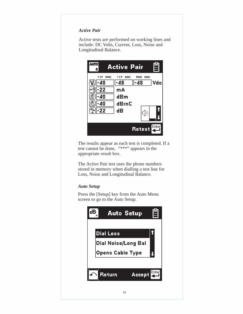
Active Pair
Active tests are performed on working lines andinclude: DC Volts, Current, Loss, Noise andLongitudinal Balance.
The results appear as each test is completed. If atest cannot be done, “***” appears in theappropriate result box.
The Active Pair test uses the phone numbersstored in memory when dialling a test line forLoss, Noise and Longitudinal Balance.
Auto Setup
Press the [Setup] key from the Auto Menuscreen to go to the Auto Setup.

36
Auto Setup (continued)
There are three choices in the Auto Setup menu:
• Dial Loss• Dial Noise/Longitudinal Balance• Opens Cable Type
Press the [Up] or [Down] keys to move to adesired selection. Press the [Enter] key to acceptthe choice. Use the [Back] key to return to theAuto Menu.
Dial Loss:
Use this setup to enter a ‘milliwatt’ or ‘Dynatel1020’ test line number for the Active Pair Lossmeasurement.
The screen and controls for the Auto Dial Losssetup are similar to the Dial Loss screen.
Dial Noise/Longitudinal Balance
Use this setup to enter a ‘quiet’ test line number(or a ‘1’ to break dial tone) for both the ActivePair Noise and Longitudinal Balancemeasurements.
The screen and controls for this setup are similaras the Dial Noise screen.
Opens Cable Type:
Use this setup to select the Cable Type used forthe Inactive Pair Opens measurement. Note thatyou may not select Capacitiance from this menu.

37
Talk Set
This function allows you to use the 965DSP-Bas a Talk Set on active pairs, or to send DTMFtones or pulses on inactive pairs.
Connect the Red and Black leads to the pair forLoop Start. Also connect the Green lead toground for Ground Start.
This screen displays the last number dialed, theDC voltage on the line, and the signal format fordialing. You can use DTMF or pulse dialing, orselect between loop or ground start.
Use the [Setup] key to change these settings orto select and edit a stored phone number.
The blue keys become number keys in Talk Set.Use the [Backup] key to exit Talk Set beforegoing to another function.
Use the [Tab] key to switch between on-hookand off-hook. Use the [Enter] key to dial (send)the number in the display.
Use the [Right] arrow key to turn themicrophone on and off.
The speaker is active during the Talk Setfunction. Use the [Up] and [Down] arrow keysto adjust the volume. The maximum volume islimited in the Talk Set function to preventunwanted feedback.

38
Talk Set Setup
Press the [Setup] key to access the telephonenumber directory.
Use the blue keys to change the number. See theEditing instructions on page 6 for additionalinformation. Press the [Enter] key to accept thechanges and return to the previous screen.
Use the [Back] key to return to the previousscreen without making changes.
Use the [Up] and [Down] arrow keys to move toa desired number. Use the [Tab] key to highlighta desired menu. Use the [Enter] key to acceptthe choice and return to the previous screen.
For any number highlighted, press the [Setup]key to edit the number.

39
Care and Maintenance
Battery Pack: The 965DSP-B uses a NickelMetal Hydride (NMH) battery pack. Typical lifeof the battery pack is two years.
To change the battery pack: 1) loosen the sixscrews on the battery compartment door andremove the door, 2) remove the old pack , then3) unplug the battery connector.
To install a new battery pack: 1) plug in thebattery connector, 2) place the pack in thebattery compartment, then 3) replace the doorand tighten the screws.
Charging:
The battery pack must be charged on a regularbasis. You can use the 965DSP-B for up to 12hours typical usage (6 hours continuous usage).
The time between charges may be reduced ifyou use the backlight frequently or if you workin very cold weather.
Typical charging time is two hours.
Level of Charge:
The battery icon in the upper right of all screensindicates the battery charge. Four black “bars”indicate full charge. Zero black “bars” indicatethe battery pack is very low and should becharged immediately.
AC/DC Adaptor:
Use the AC/DC adaptor to charge the NMHbattery pack. Plug the AC cord into the AC/DCadaptor and into a power outlet. Plug the DCcord into the 965DSP-B.
IR Port:
The IR Port on the top of the 965DSP-B is usedfor uploading new software enhancements.
An IR to RS-232 adaptor cable is provided withsoftware enhancements.
40
Battery Holder:
The plastic battery holder that comes with the965DSP-B uses six “AA” alkaline batteries(alkaline batteries are not included).
Use alkaline batteries only when the NMHbattery pack is discharged and the AC/DCadaptor is not available. Typical lifetime of thealkaline battery pack is eight hours of normaluse (less if you use the backlight or work in verycold weather).
The alkaline battery pack is installed the sameway as the NMH pack.
Test Leads:
The 965DSP-B comes with a Red/Black testlead pair, a Blue/Yellow test lead pair, and aseparate Green test lead.
The Red/Black and Green test leads are used formost measurements. The Yellow lead is usedwith RFL. The shorting ‘strap’ that comes withthe 965DSP-B is used with RFL.
Keep the test leads clean and dry at all times toinsure best accuracy of the measurements. Usesoap and water to clean them if necessary.
Replacement Items:
You may order any of the following replacementitems from 3M. Contact 3M Telecom SystemsDivision customer service at 800 426 8688 formore information.
Accessory 3M Part Number
NMH Battery Pack 80-6108-6473-0Red/Black Test Lead Pair 80-6108-6435-9Blue/Yellow Test Lead Pair 80-6108-6436-7Green Test Lead 80-6108-6437-5Ground Strap 80-6109-3830-2AC/DC Adaptor 80-6108-6393-0Carrying Case 80-6108-6392-2Alkaline Battery Holder 80-6108-6472-2

41
If the above solutions do not fix the problem,the 965DSP-B may need repair.
Please make a note of the conditions when anyfailure occurred and record any error messagesthat may have appeared on the screen, then call3M Telecom Repair Service at 800 426 8688 forfurther details on repair service.
Symptom Cause Solution
Unit does not turn on Discharged battery pack. Charge battery pack.
AC/DC adaptor Check AC/DC
NMH battery pack old. Replace battery pack.
Screen goes blank Battery voltage low. Charge battery pack.
Dark lines across screen Battery voltage low. Charge battery pack.
Error Messages Battery voltage low. Charge battery pack.
Inaccurate results Battery voltage low. Charge battery pack.
Test lead broken. Replace test lead.
Improper connections. Check Connections.
No results Test lead broken Replace test lead.
Improper connections. See on-screen
hookups.
Resistance reads less thanTest Leads dirty Clean Test Leads
999 M Ohms when test leads
disconnected.
Error messages during Test Leads not shorted Check Connections.
Self-Calibration. properly when prompted.
Repair:
Many apparent failures with the 965DSP-B canbe corrected by simple procedures.
disconnected. adaptor cords.

42
Function Range Accuracy
Voltage: 0 to 30 Vdc, Vac 0.5 V30 to 300 Vdc 0.7 V30 to 250 Vac 0.7 V
Current: -60 to 60 mA 1% +/- 0.3 mA-110 to -60 mA 2%60 to 110 mA 2%
Resistance: 0 to 100kΩ 1% +/- 5 Ω(1% +/- 50 Ω if C.O. voltage present)100kΩ to 10MΩ 3%100MΩ to 1000MΩ 10%
Load Coils: 0 to 4
Opens: 3 to 10000 ft 1% +/- 3 ft(1m to 3 km) (1% +/- 1 m)10000 to 50000 ft 5%(3 to 15km)50000 to 100000 ft 10%(15 to 30 km)
Tone: 200 to 20kHz, 1 Hz-20 to +1 dB 0.2 dB40kHz, 6dBm 10Hz, 0.5dB
RFL fault size: 0 to 20 MΩRFL loop resist.: 0 to 7000 ΩRFL fault locate: 0 to 99 Ω 0.1% of RTS
+/- 0.01 Ω100 to 999 Ω 0.2% of RTS1000 to 7000 Ω 1% of RTS
(RTS: Resistance to Strap. Distance to fault depends onthe wire gauge and temperature selected.)
Loss: -40 to 10 dBm 0.5 dB200 to 3000 Hz 2 Hz3 kHz to 20 kHz 10 Hz
Wideband Loss: -46 to 10 dBm 1 dB20k to 200kHz 100 Hz
Noise Metallic: 0 to 50 dBrnc 2 dBNoise to Ground: 40 to 100 dBrnc 2 dBAuto: (Same as individual functions)
965DSP-B Specifications:
Size: 4x10x2.5" (10x25x6 cm)Weight: 3.3 lbs (1.5 kg)Operating Temp: 0 to 140°F (-18 to 60°C)Storage Temp: -40 to 165°F (-40 to 70°C)

43
New Product Limited Warranty:
3M Telecom Systems (herein referred to as the Seller) warrantsits products to be free from defects in material andworkmanship, subject to the following terms and provisions:
a) All instruments are warranted for 12 months after date ofshipment from the Seller to the original purchaser.
b) Seller’s obligations under this warranty are limited torepairing, replacing, or adjusting at Seller’s option any ofSeller’s products which after normal and proper usage, provesto be defective on Seller’s inspection, provided that thepurchaser shall have reasonably inspected products whenreceived and notified the Seller of any apparent defects within15 days of receipt of shipment. Seller shall not be liable for anyinjury or for any manufacturing costs of the buyer, or any otherspecial consequential damages incurred by the buyer by reasonof the use of any of the Seller’s equipment.
c) Equipment delivered by the Seller shall not be considereddefective if it satisfactorily fulfills the order or complies withthe published specifications on standard catalog items. Thiswarranty does not extend to any of Seller’s products whichhave been subjected to misuse, neglect, accident or improperapplications, nor shall it extend to units which have beenrepaired or altered outside of the Seller’s factory, nor to anyassociated instruments, equipment or apparatus.
Important Purchaser Notice
All statements, recommendations, and technical informationrelated to Seller’s products are based on information believedto be reliable, but the accuracy or completeness thereof is notguaranteed. Before using the equipment, the buyer shoulddetermine the suitability of the product for the intended use,and assumes all risk and liability whatsoever in connectionwith that use.
All statements or recommendations not contained in Seller’sstandard publications shall have no force or agreement unlessan agreement signed by the officers of Seller, and the above is
made in lieu of all warranties, expressed or implied.

44
© 1997Telecom Systems Division6801 River Place Blvd.Austin, Texas 78726-9000 USA


![Dynatel 965DSP / 3M Far -End-Device Setup · 2012-01-18 · FED Ring [A] Tip [B] Shield/Ground Near-end Far-end. 11 Welcome DynatelTM 965DSP ON OFF Subscriber Loop Analyzer S/N 975100YP](https://img.dokumen.tips/doc/110x75/5f500bdceaa24770222694a8/dynatel-965dsp-3m-far-end-device-setup-2012-01-18-fed-ring-a-tip-b-shieldground.jpg)