Embed Size (px)
Citation preview

8/6/2019 TM 5-3825-270-10 ENGINEER MISSION MODULE WATER DISTRIBUTION
http://slidepdf.com/reader/full/tm-5-3825-270-10-engineer-mission-module-water-distribution 1/483
TM 5-3825-270-10
TECHNICAL MANUAL
OPERATOR'S MANUALFOR
ENGINEER MISSION MODULE - WATER DISTRIBUTOR
(EMM - WD)
NSN 3825-01-577-2713
DISTRIBUTION STATEMENTA - Approved for public release; distribution is unlimited.
HEADQUARTERS, DEPARTMENT OF THE ARMY
30 JUNE 2011

8/6/2019 TM 5-3825-270-10 ENGINEER MISSION MODULE WATER DISTRIBUTION
http://slidepdf.com/reader/full/tm-5-3825-270-10-engineer-mission-module-water-distribution 2/483

8/6/2019 TM 5-3825-270-10 ENGINEER MISSION MODULE WATER DISTRIBUTION
http://slidepdf.com/reader/full/tm-5-3825-270-10-engineer-mission-module-water-distribution 3/483
WARNING SUMMARY
GENERAL SAFETY CAUTION/WARNING SUMMARY
• This list summarizes critical warnings. They are repeated here to let you know how important they are.
• Study these warnings carefully.
• They can save your life and the lives of personnel you work with.
• If there is any doubt about handling tools, materials, equipment, and procedures, see TB 43-0216, Safetyand Hazard Warnings for Operation and Maintenance of TACOM Equipment.
FOR INFORMATION ON FIRST AID:
Reference FM 4-25.11. (WP 0086)
WARNING
MODIFICATION HAZARD• Unauthorized modifications to, alterations to, or installations on this equipment are
prohibited and are in violation of AR 750-10.
• Failure to comply may result in injury or death to personnel or damage to equipment.
WARNING
BATTERY
• To avoid eye injury, eye protection is required when working around batteries. Do notsmoke, use open flame, make sparks or create other ignition sources around batteries.If a battery is giving off gases, it can explode. Remove all jewelry, such as rings, ID tags,watches and bracelets. If jewelry contacts a battery terminal, a direct short will result ininstant heating of tools and/or damage to equipment. Failure to comply may result in injuryor death to personnel.
• Avoid electrolyte contact with skin, eyes, or clothing. If battery electrolyte spills, takeimmediate action to stop burning effects.
• External: Immediately flush with cold running water to remove all acid.
• Eyes: Flush with cold water for at least 15 minutes. Seek immediate medical attention.
• Internal: Drink large amounts of water or milk. Follow with milk of magnesia, beaten egg,or vegetable oil. Seek immediate medical attention.
• Clothing or Vehicle: Wash at once with cold water. Neutralize with baking soda or household ammonia solution.
• Injury will result if acid contacts skin or eyes. Wear rubber apron to prevent clothing frombeing damaged. Failure to comply may result in injury or death to personnel.
TM 5-3825-270-10
a

8/6/2019 TM 5-3825-270-10 ENGINEER MISSION MODULE WATER DISTRIBUTION
http://slidepdf.com/reader/full/tm-5-3825-270-10-engineer-mission-module-water-distribution 4/483
WARNING SUMMARY - Continued
WARNING
FIRE EXTINGUISHER
• Fire extinguisher contents are under pressure. Do not puncture or incinerate.
• DO NOT store at high temperatures above 120°F (49°C).
• Avoid inhaling the extinguishing agent. Avoid inhaling smoke and fumes - all fires releasetoxic substances that are harmful. DO NOT remain in a closed area after use. Evacuatethe area immediately and ventilate thoroughly before re-entering.
• Although extinguishing agents are non-toxic when properly used, contact with them may
cause irritation to eyes, nose, and throat and other allergic symptoms.• Failure to comply with the above warnings could result in injury or death to personnel or
damage to equipment.
WARNING
SOLVENT CLEANING COMPOUND (DRYCLEANING SOLVENT)
• Solvent cleaning compound MIL-PRF-680 Type II and III may be irritating to the eyes and
skin. Use protective gloves and goggles. Use in a well-ventilated area. Use respirator asneeded. Accidental ingestion can cause irritation of digestive tract and respiratory tract,may cause lung and central nervous system damage. Can be fatal if swallowed.Inhalation of high/massive concentrations can cause coma or be fatal. First aid for ingestion: do not induce vomiting. Seek immediate medical attention. First aid for skincontact: remove contaminated clothing. Wash skin thoroughly with soap and water. If symptoms persist, seek medical attention. First aid for eye contact: flush with water for 15 minutes or until irritation subsides. If symptoms persist, seek medical attention. Firstaid for inhalation: move to fresh air. If not breathing, provide artificial respiration. If symptoms persist, seek medical attention. Keep away from open flames and other sources of ignition. Failure to comply may result in injury or death to personnel.
• The flashpoint for Type II solvent cleaning compound is 141 to 198°F (61 to 92°C), andType III is 200 to 241°F (93 to 116°C).
• Improper cleaning methods and use of unauthorized cleaning solvents may result in injuryto personnel and/or damage to equipment.
• Fire extinguishers should be placed nearby when using solvent cleaning compound.Failure to comply may result in injury or death to personnel.
• Cloths or rags saturated with solvent cleaning compound must be disposed of IAWauthorized facilities' procedures. Failure to comply may result in injury to personnel.
TM 5-3825-270-10
b

8/6/2019 TM 5-3825-270-10 ENGINEER MISSION MODULE WATER DISTRIBUTION
http://slidepdf.com/reader/full/tm-5-3825-270-10-engineer-mission-module-water-distribution 5/483
WARNING SUMMARY - Continued
• Eye shields must be worn when cleaning with a wire brush. Failure to comply may resultin injury to personnel.
• If personnel become dizzy while using cleaning solvent, immediately get fresh air andmedical help. If solvent contacts skin or clothes, flush with cold water. If solvent contactseyes, immediately flush eyes with water and get immediate medical attention. Failure tocomply may result in injury or death to personnel.
WARNING
EXTREME HEAT
When mission requires the system operator and crew to remain stationary at an area or location in outside temperatures above 90°F (32°C), operator and crew must observe proper safety precautions to prevent heat stress injury. Refer to FM 21-10, Field Hygiene and Sanitation , and FM 4-25.11, First Aid for Soldiers , for proper precautions and preventivemeasures. Failure to comply may result in injury or death to personnel.
WARNING
EXTREME COLD
• DO NOT touch extremely cold metal. Bare skin may freeze to cold metal. Failure tocomply may result in injury or death to personnel.
• Wear gloves when operating or handling metallic equipment that is wet or ice covered.Failure to comply may result in injury or death to personnel.
• Exercise caution when working on the catwalk where snow or ice exists. Failure to complymay result in injury or death to personnel.
WARNING
LOAD HANDLING SYSTEM OPERATION
• Check for overhead power lines or other obstructions before attempting LHS operations.
LHS reaches a height of 18 ft (5.5 m). Injury or death to personnel could result if LHScontacts power lines.
• Do not attempt loading or unloading operations on a side slope greater than 5 degreesand/or fore/aft slope greater than 20%. Prior to performing loading or unloadingoperations on slopes, determine if ground surface conditions permit safe loading or unloading operations. Slopes that contain snow, ice, loose gravel, or sand may not permitsafe loading or unloading. Failure to comply may result in injury or death to personnel.
TM 5-3825-270-10
c

8/6/2019 TM 5-3825-270-10 ENGINEER MISSION MODULE WATER DISTRIBUTION
http://slidepdf.com/reader/full/tm-5-3825-270-10-engineer-mission-module-water-distribution 6/483
WARNING SUMMARY - Continued
• Check ground conditions for firmness and extreme sideways inclination prior to pickingup or off-loading a Water Distributor. Failure to comply may result in damage to equipmentand injury or death to personnel.
• Prior to and during any load or unload cycle, all personnel should stay clear of LHS.Failure to comply may result in damage to equipment and injury or death to personnel.
WARNING
COOLING SYSTEM PRESSURE
• Use extreme care when removing radiator pressure cap. Sudden release of pressure can
cause steam flash. Slowly loosen cap to the first stop to relieve pressure prior to removingcap completely. Failure to comply may result in injury or death to personnel.
• Use clean, thick waste cloth or like material to remove radiator pressure cap. Avoid usinggloves, hot water soaks through gloves. Failure to comply may result in injury or deathto personnel.
• Wear suitable eye protection when working on vehicle cooling systems to avoid personalinjury.
WARNING
ENGINE STARTING
• When engine is running during operations, all personnel within 10 ft of the Water Distributor pump operator position are required to wear Army-approved hearingprotection devices (HPDs). Failure to comply may result in hearing loss.
• Before engine is started, always make sure that no personnel are in the danger area(moving parts on engine or machinery). Ensure that all safety guards are in place. Ensurethat area is clear from loose parts. Never use any spray starting aids. Failure to complymay result in injury or death to personnel.
WARNING
FUEL
• Diesel fuel is flammable. Do not perform this procedure near fire, flame or sparks. Failureto comply may result in injury or death to personnel.
TM 5-3825-270-10
d
8/6/2019 TM 5-3825-270-10 ENGINEER MISSION MODULE WATER DISTRIBUTION
http://slidepdf.com/reader/full/tm-5-3825-270-10-engineer-mission-module-water-distribution 7/483
WARNING SUMMARY - Continued
• DO NOT smoke or permit any open flame in area of Water Distributor while you areservicing fuel system. Be sure hose nozzle is grounded against filler tube during refuelingto prevent static electricity. Failure to comply may result in injury or death to personnel.
• DO NOT perform fuel system checks, inspections, or maintenance while smoking or near fire, flames, or sparks. Fuel may ignite, causing injury or death to personnel, or damageto equipment.
• Operating personnel must wear fuel-resistant gloves when handling fuels. If exposed tofuel, promptly wash exposed skin and change fuel-soaked clothing.
WARNING
HOT ENGINE
Engine components become hot during normal operation. Allow engine to cool completelyprior to performing this task. If necessary, use insulated pads and gloves. Failure to complymay result in injury or death to personnel.
WARNING
ELECTRICAL SYSTEM
• Ensure electrical power is off prior to working on all electrical systems. Failure to complymay result in injury or death to personnel.
• Remove all jewelry, such as rings, ID tags, bracelets, etc., prior to working on or aroundequipment. Jewelry and tools can catch on equipment, contact positive electrical circuits,and cause a direct short, severe burns, or electrical shock. Failure to comply may resultin injury or death to personnel.
WARNING
HOT EXHAUST
Exhaust pipes and muffler can become very hot during engine operation. Allow parts to cooland take care not to touch these parts with bare hands or allow body to contact exhaust pipesor muffler. Failure to comply may result in injury or death to personnel.
TM 5-3825-270-10
e

8/6/2019 TM 5-3825-270-10 ENGINEER MISSION MODULE WATER DISTRIBUTION
http://slidepdf.com/reader/full/tm-5-3825-270-10-engineer-mission-module-water-distribution 8/483
WARNING SUMMARY - Continued
WARNING
LIFTING OPERATIONS
This section is applicable to all lifting operations regardless of lifting equipment (crane, LHS,etc.) used.
All personnel must stand clear during lifting operations. A swinging or shifting load may causeinjury or death to personnel.
Never crawl under equipment when performing maintenance unless equipment is securelyblocked. Failure to comply may cause injury or death to personnel.
Keep clear of equipment when it is being raised or lowered. Failure to comply may causeinjury or death to personnel.
Do not work on any item supported only by lift jacks or hoist. Always use blocks or proper stands to support the item prior to any work. Failure to comply may result in injury or deathto personnel.
Do not lift a load greater than the rated load capacity of the crane or materiel handlingequipment. Failure to comply may result in injury or death to personnel or damage toequipment.
Do not allow heavy components to swing while hanging by lifting device. Failure to complymay cause injury or death to personnel.
Any part or component that weighs between 50 lbs (23 kg) and 75 lbs (34 kg) must beremoved with the aid of an assistant. Any part or component that weighs over 75 lbs (34 kg)must be removed with the aid of an assistant and a lifting device. Failure to comply may causeinjury or death to personnel.
Ensure all chains, hooks, and slings are in good condition and are of correct capacity. Ensurehooks are positioned correctly. Failure to comply may result in injury or death to personnel.
WARNING
MOVING MACHINERYUse extreme care when operating or working near moving machinery including runningengine, rotating shafts, and other moving parts. Failure to comply may result in injury or deathto personnel.
Use extreme care when measuring voltage while engine is running around rotating fan bladeand hot engine parts. Failure to comply may result in injury or death to personnel.
TM 5-3825-270-10
f

8/6/2019 TM 5-3825-270-10 ENGINEER MISSION MODULE WATER DISTRIBUTION
http://slidepdf.com/reader/full/tm-5-3825-270-10-engineer-mission-module-water-distribution 9/483
WARNING SUMMARY - Continued
WARNING
HEARING PROTECTION
Wear single hearing protection (earplugs or equivalent) while working around equipmentwhile it is running. Failure to do so could result in damage to your hearing.
Seek medical aid should you suspect a hearing problem.
WARNING
EYE PROTECTION
Wear safety goggles and use caution when removing or installing springs, snap ring, retainingrings, and other parts under spring tension. These parts can act as projectiles, resulting inserious injury to personnel. Failure to comply may result in injury or death to personnel.
TM 5-3825-270-10
g/h blank

8/6/2019 TM 5-3825-270-10 ENGINEER MISSION MODULE WATER DISTRIBUTION
http://slidepdf.com/reader/full/tm-5-3825-270-10-engineer-mission-module-water-distribution 10/483

8/6/2019 TM 5-3825-270-10 ENGINEER MISSION MODULE WATER DISTRIBUTION
http://slidepdf.com/reader/full/tm-5-3825-270-10-engineer-mission-module-water-distribution 11/483
TM 5-3825-270-10
A
LIST OF EFFECTIVE PAGES/WORK PACKAGES
NOTE: Zero in the “Change No.” column indicates an original page or work package.
Date of issue for the original manual is:
Original 30 June 2011
TOTAL NUMBER OF PAGES FOR FRONT AND REAR MATTER IS 50 AND TOTAL NUMBER OF
WORK PACKAGES IS 89, CONSISTING OF THE FOLLOWING:
CHANGE
PAGE/WP NO. NO.
CHANGE
PAGE/WP NO. NO.
Front Cover 0
Blank 0
Warning Summary (8 pages) 0
i 0
Blank 0iii-xxi 0
Blank 0
xxii 0
Blank 0
Chp 1 - title page 0
Blank 0
WP 0001 (8 pages) 0
WP 0002 (4 pages) 0
WP 0003 (2 pages) 0
Chp 2 - title page 0
Blank 0
WP 0004 (6 pages) 0WP 0005 (2 pages) 0
WP 0006 (4 pages) 0
WP 0007 (2 pages) 0
WP 0008 (2 pages) 0
WP 0009 (2 pages) 0
WP 0010 (12 pages) 0
WP 0011 (2 pages) 0
WP 0012 (16 pages) 0
WP 0013 (2 pages) 0
WP 0014 (4 pages) 0
WP 0015 (10 pages) 0
WP 0016 (10 pages) 0
WP 0017 (6 pages) 0
WP 0018 (6 pages) 0
WP 0019 (4 pages) 0
WP 0020 (14 pages) 0
WP 0021 (12 pages) 0
WP 0022 (4 pages) 0
WP 0023 (4 pages) 0
WP 0024 (14 pages) 0
WP 0025 (2 pages) 0
WP 0026 (2 pages) 0
WP 0027 (2 pages) 0
Chp 3 - title page 0
Blank 0WP 0028 (2 pages) 0
WP 0029 (2 pages) 0
WP 0030 (4 pages) 0
WP 0031 (4 pages) 0
WP 0032 (2 pages) 0
WP 0033 (2 pages) 0
WP 0034 (2 pages) 0
WP 0035 (2 pages) 0
WP 0036 (2 pages) 0
WP 0037 (2 pages) 0
WP 0038 (2 pages) 0
WP 0039 (2 pages) 0WP 0040 (2 pages) 0
WP 0041 (2 pages) 0
WP 0042 (2 pages) 0
WP 0043 (2 pages) 0
WP 0044 (4 pages) 0
WP 0045 (4 pages) 0
WP 0046 (2 pages) 0
WP 0047 (2 pages) 0
WP 0048 (4 pages) 0
WP 0049 (2 pages) 0
WP 0050 (2 pages) 0
WP 0051 (2 pages) 0
WP 0052 (2 pages) 0
WP 0053 (2 pages) 0
WP 0054 (2 pages) 0
WP 0055 (2 pages) 0
WP 0056 (2 pages) 0
WP 0057 (2 pages) 0
WP 0058 (4 pages) 0
WP 0059 (2 pages) 0
8/6/2019 TM 5-3825-270-10 ENGINEER MISSION MODULE WATER DISTRIBUTION
http://slidepdf.com/reader/full/tm-5-3825-270-10-engineer-mission-module-water-distribution 12/483
TM 5-3825-270-10
B
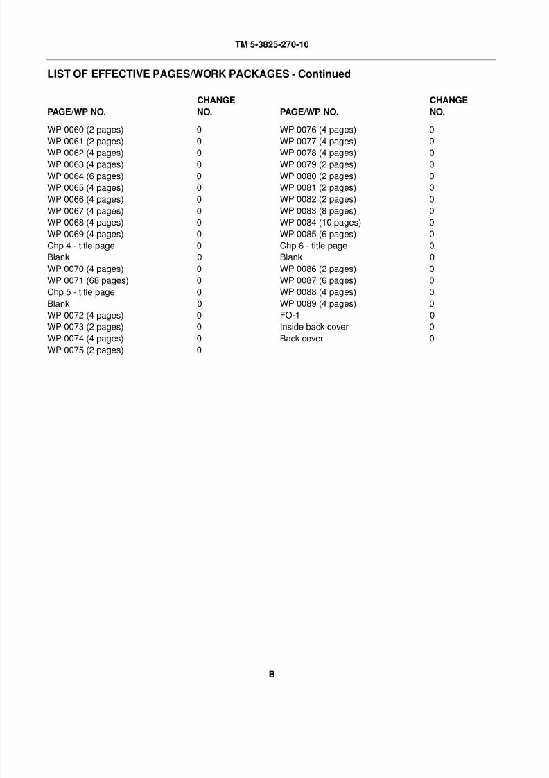
LIST OF EFFECTIVE PAGES/WORK PACKAGES - Continued
CHANGE
PAGE/WP NO. NO.
CHANGE
PAGE/WP NO. NO.
WP 0060 (2 pages) 0
WP 0061 (2 pages) 0
WP 0062 (4 pages) 0
WP 0063 (4 pages) 0
WP 0064 (6 pages) 0
WP 0065 (4 pages) 0
WP 0066 (4 pages) 0
WP 0067 (4 pages) 0
WP 0068 (4 pages) 0
WP 0069 (4 pages) 0
Chp 4 - title page 0
Blank 0
WP 0070 (4 pages) 0WP 0071 (68 pages) 0
Chp 5 - title page 0
Blank 0
WP 0072 (4 pages) 0
WP 0073 (2 pages) 0
WP 0074 (4 pages) 0
WP 0075 (2 pages) 0
WP 0076 (4 pages) 0
WP 0077 (4 pages) 0
WP 0078 (4 pages) 0
WP 0079 (2 pages) 0
WP 0080 (2 pages) 0
WP 0081 (2 pages) 0
WP 0082 (2 pages) 0
WP 0083 (8 pages) 0
WP 0084 (10 pages) 0
WP 0085 (6 pages) 0
Chp 6 - title page 0
Blank 0
WP 0086 (2 pages) 0WP 0087 (6 pages) 0
WP 0088 (4 pages) 0
WP 0089 (4 pages) 0
FO-1 0
Inside back cover 0
Back cover 0
8/6/2019 TM 5-3825-270-10 ENGINEER MISSION MODULE WATER DISTRIBUTION
http://slidepdf.com/reader/full/tm-5-3825-270-10-engineer-mission-module-water-distribution 13/483
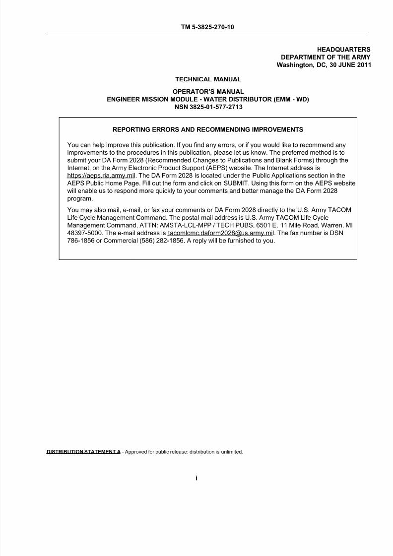
HEADQUARTERS
DEPARTMENT OF THE ARMY
Washington, DC, 30 JUNE 201
TECHNICAL MANUAL
OPERATOR’S MANUAL
ENGINEER MISSION MODULE - WATER DISTRIBUTOR (EMM - WD)NSN 3825-01-577-2713
REPORTING ERRORS AND RECOMMENDING IMPROVEMENTS
You can help improve this publication. If you find any errors, or if you would like to recommend any
improvements to the procedures in this publication, please let us know. The preferred method is to
submit your DA Form 2028 (Recommended Changes to Publications and Blank Forms) through the
Internet, on the Army Electronic Product Support (AEPS) website. The Internet address is
https://aeps.ria.army.mil. The DA Form 2028 is located under the Public Applications section in the
AEPS Public Home Page. Fill out the form and click on SUBMIT. Using this form on the AEPS website
will enable us to respond more quickly to your comments and better manage the DA Form 2028
program.
You may also mail, e-mail, or fax your comments or DA Form 2028 directly to the U.S. Army TACOM
Life Cycle Management Command. The postal mail address is U.S. Army TACOM Life Cycle
Management Command, ATTN: AMSTA-LCL-MPP / TECH PUBS, 6501 E. 11 Mile Road, Warren, MI
48397-5000. The e-mail address is [email protected]. The fax number is DSN
786-1856 or Commercial (586) 282-1856. A reply will be furnished to you.
DISTRIBUTIONSTATEMENT A - Approved for public release: distribution is unlimited.
TM 5-3825-270-10
i

8/6/2019 TM 5-3825-270-10 ENGINEER MISSION MODULE WATER DISTRIBUTION
http://slidepdf.com/reader/full/tm-5-3825-270-10-engineer-mission-module-water-distribution 14/483
TABLE OF CONTENTS
Page No
WP Sequence No
How to Use this Manual
Chapter 1 - GENERAL INFORMATION, EQUIPMENT DESCRIPTION, AND THEORY OF
OPERATION
GENERAL INFORMATION.......................................................................................................................... WP 0001
Table 1. List of Abbreviations............................................................................................................. 0001-2
Table 2. Warning Icons...................................................................................................................... 0001-4
EQUIPMENT DESCRIPTION AND DATA................................................................................................... WP 0002
Table 1. Equipment Data.................................................................................................................... 0002-1
THEORY OF OPERATION.......................................................................................................................... WP 0003
Chapter 2 - OPERATOR INSTRUCTIONS
LOCATIONS AND USE OF CONTROLS AND INDICATORS.................................................................... WP 0004
Table 1. MAIN CONTROL PANEL..................................................................................................... 0004-1
Figure 1. Control Panel........................................................................................................................ 0004-1
Figure 2. Control Panel........................................................................................................................ 0004-2
Figure 3. Control Panel........................................................................................................................ 0004-3
Table 2. CAB CONTROL PANEL....................................................................................................... 0004-4
Figure 4. Cab Control Panel................................................................................................................ 0004-4
Table 3. VALVES............................................................................................................................... 0004-5
Figure 5. Valves................................................................................................................................... 0004-5
Figure 6. Valves................................................................................................................................... 0004-6
PREPARATION FOR OPERATION/ENGINE START-UP........................................................................... WP 0005
OPERATING LIGHTS.................................................................................................................................. WP 0006
Figure 1. Operating Lights................................................................................................................... 0006-1
Figure 2. Operating Lights................................................................................................................... 0006-2
Figure 3. Operating Lights................................................................................................................... 0006-2
Figure 4. Operating Lights................................................................................................................... 0006-3
LOADING/UNLOADING WATER DISTRIBUTOR ON PLS OR TRAILER.................................................. WP 0007
FUELING..................................................................................................................................................... WP 0008
TM 5-3825-270-10
ii
8/6/2019 TM 5-3825-270-10 ENGINEER MISSION MODULE WATER DISTRIBUTION
http://slidepdf.com/reader/full/tm-5-3825-270-10-engineer-mission-module-water-distribution 15/483
TABLE OF CONTENTS - Continued
Page No.
WP Sequence No.
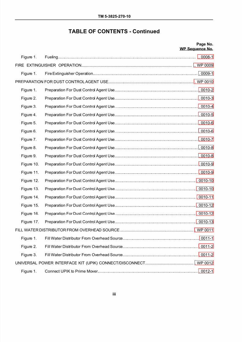
Figure 1. Fueling.................................................................................................................................. 0008-1
FIRE EXTINGUISHER OPERATION........................................................................................................... WP 0009
Figure 1. Fire Extinguisher Operation.................................................................................................. 0009-1
PREPARATION FOR DUST CONTROL AGENT USE............................................................................... WP 0010
Figure 1. Preparation For Dust Control Agent Use.............................................................................. 0010-2
Figure 2. Preparation For Dust Control Agent Use.............................................................................. 0010-3
Figure 3. Preparation For Dust Control Agent Use.............................................................................. 0010-4
Figure 4. Preparation For Dust Control Agent Use.............................................................................. 0010-5
Figure 5. Preparation For Dust Control Agent Use.............................................................................. 0010-6
Figure 6. Preparation For Dust Control Agent Use.............................................................................. 0010-6
Figure 7. Preparation For Dust Control Agent Use.............................................................................. 0010-7
Figure 8. Preparation For Dust Control Agent Use.............................................................................. 0010-8
Figure 9. Preparation For Dust Control Agent Use.............................................................................. 0010-8
Figure 10. Preparation For Dust Control Agent Use.............................................................................. 0010-9
Figure 11. Preparation For Dust Control Agent Use.............................................................................. 0010-9
Figure 12. Preparation For Dust Control Agent Use............................................................................ 0010-10
Figure 13. Preparation For Dust Control Agent Use............................................................................ 0010-10
Figure 14. Preparation For Dust Control Agent Use............................................................................ 0010-11
Figure 15. Preparation For Dust Control Agent Use............................................................................ 0010-12
Figure 16. Preparation For Dust Control Agent Use............................................................................ 0010-12
Figure 17. Preparation For Dust Control Agent Use............................................................................ 0010-13
FILL WATER DISTRIBUTOR FROM OVERHEAD SOURCE .................................................................... WP 0011
Figure 1. Fill Water Distributor From Overhead Source...................................................................... 0011-1
Figure 2. Fill Water Distributor From Overhead Source...................................................................... 0011-2
Figure 3. Fill Water Distributor From Overhead Source...................................................................... 0011-2
UNIVERSAL POWER INTERFACE KIT (UPIK) CONNECT/DISCONNECT............................................... WP 0012
Figure 1. Connect UPIK to Prime Mover............................................................................................. 0012-1
TM 5-3825-270-10
iii
8/6/2019 TM 5-3825-270-10 ENGINEER MISSION MODULE WATER DISTRIBUTION
http://slidepdf.com/reader/full/tm-5-3825-270-10-engineer-mission-module-water-distribution 16/483
TABLE OF CONTENTS - Continued
Page No
WP Sequence No
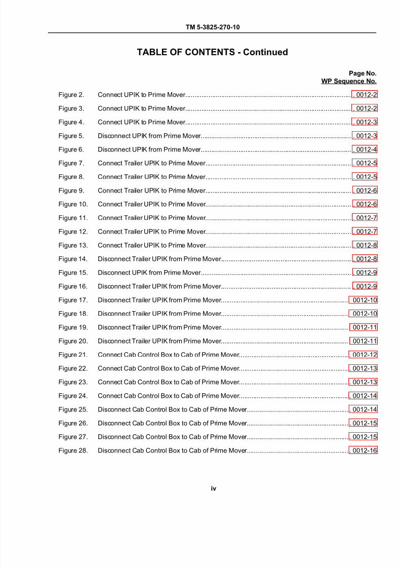
Figure 2. Connect UPIK to Prime Mover............................................................................................. 0012-2
Figure 3. Connect UPIK to Prime Mover............................................................................................. 0012-2
Figure 4. Connect UPIK to Prime Mover............................................................................................. 0012-3
Figure 5. Disconnect UPIK from Prime Mover..................................................................................... 0012-3
Figure 6. Disconnect UPIK from Prime Mover..................................................................................... 0012-4
Figure 7. Connect Trailer UPIK to Prime Mover.................................................................................. 0012-5
Figure 8. Connect Trailer UPIK to Prime Mover.................................................................................. 0012-5
Figure 9. Connect Trailer UPIK to Prime Mover.................................................................................. 0012-6
Figure 10. Connect Trailer UPIK to Prime Mover.................................................................................. 0012-6
Figure 11. Connect Trailer UPIK to Prime Mover.................................................................................. 0012-7
Figure 12. Connect Trailer UPIK to Prime Mover.................................................................................. 0012-7
Figure 13. Connect Trailer UPIK to Prime Mover.................................................................................. 0012-8
Figure 14. Disconnect Trailer UPIK from Prime Mover......................................................................... 0012-8
Figure 15. Disconnect UPIK from Prime Mover..................................................................................... 0012-9
Figure 16. Disconnect Trailer UPIK from Prime Mover......................................................................... 0012-9
Figure 17. Disconnect Trailer UPIK from Prime Mover....................................................................... 0012-10
Figure 18. Disconnect Trailer UPIK from Prime Mover....................................................................... 0012-10
Figure 19. Disconnect Trailer UPIK from Prime Mover....................................................................... 0012-11
Figure 20. Disconnect Trailer UPIK from Prime Mover....................................................................... 0012-11
Figure 21. Connect Cab Control Box to Cab of Prime Mover.............................................................. 0012-12
Figure 22. Connect Cab Control Box to Cab of Prime Mover.............................................................. 0012-13
Figure 23. Connect Cab Control Box to Cab of Prime Mover.............................................................. 0012-13
Figure 24. Connect Cab Control Box to Cab of Prime Mover.............................................................. 0012-14
Figure 25. Disconnect Cab Control Box to Cab of Prime Mover......................................................... 0012-14
Figure 26. Disconnect Cab Control Box to Cab of Prime Mover......................................................... 0012-15
Figure 27. Disconnect Cab Control Box to Cab of Prime Mover......................................................... 0012-15
Figure 28. Disconnect Cab Control Box to Cab of Prime Mover......................................................... 0012-16
TM 5-3825-270-10
iv

8/6/2019 TM 5-3825-270-10 ENGINEER MISSION MODULE WATER DISTRIBUTION
http://slidepdf.com/reader/full/tm-5-3825-270-10-engineer-mission-module-water-distribution 17/483
TABLE OF CONTENTS - Continued
Page No.
WP Sequence No.
DISCHARGE FROM GRAVITY SPRINKLER BAR..................................................................................... WP 0013
Figure 1. Discharge From Gravity Sprinkler Bar.................................................................................. 0013-1
SPRINKLER HEAD ADJUSTMENT............................................................................................................ WP 0014
Figure 1. Sprinkler Head Adjustment................................................................................................... 0014-1
Figure 2. 2 Ft. Width............................................................................................................................ 0014-2
Figure 3. 20 Ft. Width.......................................................................................................................... 0014-2
Figure 4. 40 Ft. Width.......................................................................................................................... 0014-3
Figure 5. 80 Ft. Width.......................................................................................................................... 0014-4
DISCHARGE FROM WATER TURRET ASSEMBLY.................................................................................. WP 0015
Figure 1. Discharge From Water Turret Assembly.............................................................................. 0015-1
Figure 2. Discharge From Water Turret Assembly.............................................................................. 0015-2
Figure 3. Discharge From Water Turret Assembly.............................................................................. 0015-2
Figure 4. Discharge From Water Turret Assembly.............................................................................. 0015-3
Figure 5. Discharge From Water Turret Assembly.............................................................................. 0015-3
Figure 6. Discharge From Water Turret Assembly.............................................................................. 0015-4
Figure 7. Discharge From Water Turret Assembly.............................................................................. 0015-5
Figure 8. Discharge From Water Turret Assembly.............................................................................. 0015-5
Figure 9. Discharge From Water Turret Assembly.............................................................................. 0015-6
Figure 10. Discharge From Water Turret Assembly.............................................................................. 0015-6
Figure 11. Discharge From Water Turret Assembly.............................................................................. 0015-7
Figure 12. Discharge From Water Turret Assembly.............................................................................. 0015-7
Figure 13. Discharge From Water Turret Assembly.............................................................................. 0015-8
Figure 14. Discharge From Water Turret Assembly.............................................................................. 0015-8
Figure 15. Discharge From Water Turret Assembly.............................................................................. 0015-9
Figure 16. Discharge From Water Turret Assembly.............................................................................. 0015-9
Figure 17. Discharge From Water Turret Assembly............................................................................ 0015-10
Figure 18. Discharge From Water Turret Assembly............................................................................ 0015-10
TM 5-3825-270-10
v

8/6/2019 TM 5-3825-270-10 ENGINEER MISSION MODULE WATER DISTRIBUTION
http://slidepdf.com/reader/full/tm-5-3825-270-10-engineer-mission-module-water-distribution 18/483
TABLE OF CONTENTS - Continued
Page No
WP Sequence No
DISCHARGE FROM SPRINKLER NOZZLES............................................................................................. WP 0016
Figure 1. Discharge From Sprinkler Nozzles From Platform............................................................... 0016-1
Figure 2. Discharge From Sprinkler Nozzles From Platform............................................................... 0016-2
Figure 3. Discharge From Sprinkler Nozzles From Platform............................................................... 0016-2
Figure 4. Discharge From Sprinkler Nozzles From Platform............................................................... 0016-3
Figure 5. Discharge From Sprinkler Nozzles From Platform............................................................... 0016-4
Figure 6. Discharge From Sprinkler Nozzles From Platform............................................................... 0016-4
Figure 7. Discharge From Sprinkler Nozzles From Platform............................................................... 0016-5
Figure 8. Discharge From Sprinkler Nozzles From Cab of Prime Mover............................................ 0016-6
Figure 9. Discharge From Sprinkler Nozzles From Cab of Prime Mover............................................ 0016-6
Figure 10. Application Chart. (Front)..................................................................................................... 0016-7
Figure 11. Application Chart. (Rear)...................................................................................................... 0016-8
Figure 12. Typical Sprinkler Nozzle Water Delivery.............................................................................. 0016-9
Figure 13. Discharge From Sprinkler Nozzles From Cab of Prime Mover............................................ 0016-9
Figure 14. Discharge From Sprinkler Nozzles From Cab of Prime Mover.......................................... 0016-10
Figure 15. Discharge From Sprinkler Nozzles From Cab of Prime Mover.......................................... 0016-10
DISCHARGE FROM HOSE REEL ASSEMBLY.......................................................................................... WP 0017
Figure 1. Discharge From Hose Reel Assembly................................................................................. 0017-1
Figure 2. Discharge From Hose Reel Assembly................................................................................. 0017-2
Figure 3. Discharge From Hose Reel Assembly................................................................................. 0017-2
Figure 4. Discharge From Hose Reel Assembly................................................................................. 0017-3
Figure 5. Discharge From Hose Reel Assembly................................................................................. 0017-4
Figure 6. Discharge From Hose Reel Assembly................................................................................. 0017-4
Figure 7. Discharge From Hose Reel Assembly................................................................................. 0017-5
Figure 8. Discharge From Hose Reel Assembly................................................................................. 0017-6
Figure 9. Discharge From Hose Reel Assembly................................................................................. 0017-6
CIRCULATE TANK WITH PUMP TO BLEND OR RINSE........................................................................... WP 0018
TM 5-3825-270-10
vi

8/6/2019 TM 5-3825-270-10 ENGINEER MISSION MODULE WATER DISTRIBUTION
http://slidepdf.com/reader/full/tm-5-3825-270-10-engineer-mission-module-water-distribution 19/483
TABLE OF CONTENTS - Continued
Page No.
WP Sequence No.
Figure 1. Circulate Tank With Pump To Blend Or Rinse..................................................................... 0018-1
Figure 2. Circulate Tank With Pump To Blend Or Rinse..................................................................... 0018-2
Figure 3. Circulate Tank With Pump To Blend Or Rinse..................................................................... 0018-2
Figure 4. Circulate Tank With Pump To Blend Or Rinse..................................................................... 0018-3
Figure 5. Circulate Tank With Pump To Blend Or Rinse..................................................................... 0018-4
Figure 6. Circulate Tank With Pump To Blend Or Rinse..................................................................... 0018-4
Figure 7. Circulate Tank With Pump To Blend Or Rinse..................................................................... 0018-5
PRIME FULLY DRAINED PUMP................................................................................................................. WP 0019
Figure 1. Prime Fully Drained Pump................................................................................................... 0019-1
Figure 2. Prime Fully Drained Pump................................................................................................... 0019-2
Figure 3. Prime Fully Drained Pump................................................................................................... 0019-3
Figure 4. Prime Fully Drained Pump................................................................................................... 0019-4
Figure 5. Prime Fully Drained Pump................................................................................................... 0019-4
LOAD TANK AT STRAINER WITH SYSTEM PUMP AND 3" HOSE.......................................................... WP 0020
Figure 1. Load Tank At Strainer With System Pump And Floating Strainer........................................ 0020-1
Figure 2. Load Tank At Strainer With System Pump And Floating Strainer........................................ 0020-2
Figure 3. Load Tank At Strainer With System Pump And Floating Strainer........................................ 0020-2
Figure 4. Load Tank At Strainer With System Pump And Floating Strainer........................................ 0020-3
Figure 5. Load Tank At Strainer With System Pump And Floating Strainer........................................ 0020-3
Figure 6. Load Tank At Strainer With System Pump And Floating Strainer........................................ 0020-4
Figure 7. Load Tank At Strainer With System Pump And Floating Strainer........................................ 0020-5
Figure 8. Load Tank At Strainer With System Pump And Floating Strainer........................................ 0020-5
Figure 9. Load Tank At Strainer With System Pump And Floating Strainer........................................ 0020-6
Figure 10. Load Tank At Strainer With System Pump And Floating Strainer........................................ 0020-7
Figure 11. Load Tank At Strainer With System Pump And Floating Strainer........................................ 0020-8
Figure 12. Load Tank At Strainer With System Pump And Floating Strainer........................................ 0020-9
Figure 13. Load Tank At Strainer With System Pump And Floating Strainer........................................ 0020-9
TM 5-3825-270-10
vii

8/6/2019 TM 5-3825-270-10 ENGINEER MISSION MODULE WATER DISTRIBUTION
http://slidepdf.com/reader/full/tm-5-3825-270-10-engineer-mission-module-water-distribution 20/483
TABLE OF CONTENTS - Continued
Page No
WP Sequence No
Figure 14. Load Tank At Strainer With System Pump And Floating Strainer...................................... 0020-10
Figure 15. Load Tank At Strainer With System Pump And Floating Strainer...................................... 0020-10
Figure 16. Load Tank At Strainer With System Pump And Floating Strainer...................................... 0020-11
Figure 17. Load Tank At Strainer With System Pump And Floating Strainer...................................... 0020-11
Figure 18. Load Tank At Strainer With System Pump And Floating Strainer...................................... 0020-12
Figure 19. Load Tank At Strainer With System Pump And Floating Strainer...................................... 0020-12
Figure 20. Load Tank At Strainer With System Pump And Floating Strainer...................................... 0020-13
LOAD TANK AT STRAINER WITH EXTERNAL PUMP.............................................................................. WP 0021
Figure 1. Load Tank At Strainer With External Pump.......................................................................... 0021-2
Figure 2. Load Tank At Strainer With External Pump.......................................................................... 0021-3
Figure 3. Load Tank At Strainer With External Pump.......................................................................... 0021-4
Figure 4. Load Tank At Strainer With Hydrant..................................................................................... 0021-5
Figure 5. Load Tank At Strainer With Hydrant..................................................................................... 0021-5
Figure 6. Load Tank At Strainer With Hydrant..................................................................................... 0021-6
Figure 7. Load Tank At Strainer With Hydrant..................................................................................... 0021-6
Figure 8. Load Tank At Strainer With Hydrant..................................................................................... 0021-7
Figure 9. Load Tank At Strainer With Hydrant..................................................................................... 0021-7
Figure 10. Load Tank At Strainer With Hydrant..................................................................................... 0021-8
Figure 11. Load Tank At Strainer With Hydrant..................................................................................... 0021-9
Figure 12. Load Tank At Strainer With Hydrant..................................................................................... 0021-9
Figure 13. Load Tank At Strainer With Hydrant................................................................................... 0021-10
Figure 14. Load Tank At Strainer With Hydrant................................................................................... 0021-10
Figure 15. Load Tank At Strainer With Hydrant................................................................................... 0021-11
Figure 16. Load Tank At Strainer With Hydrant................................................................................... 0021-11
LOAD TANK WITH EXTERNAL 2.5" AND 5" HOSES................................................................................. WP 0022
Figure 1. Load Tank With External 2.5" Hose..................................................................................... 0022-1
Figure 2. Load Tank With 5" Hose....................................................................................................... 0022-2
TM 5-3825-270-10
viii

8/6/2019 TM 5-3825-270-10 ENGINEER MISSION MODULE WATER DISTRIBUTION
http://slidepdf.com/reader/full/tm-5-3825-270-10-engineer-mission-module-water-distribution 21/483
TABLE OF CONTENTS - Continued
Page No.
WP Sequence No.
EMPTY TANK WITHOUT PUMP................................................................................................................. WP 0023
Figure 1. Empty Tank Without Pump................................................................................................... 0023-1
Figure 2. Empty Tank Without Pump................................................................................................... 0023-2
Figure 3. Empty Tank Without Pump................................................................................................... 0023-2
Figure 4. Empty Tank Without Pump................................................................................................... 0023-3
Figure 5. Empty Tank Without Pump................................................................................................... 0023-3
FULLY DRAIN SYSTEM FOR COLD WEATHER....................................................................................... WP 0024
Figure 1. Fully Drain System For Cold Weather.................................................................................. 0024-1
Figure 2. Fully Drain System For Cold Weather.................................................................................. 0024-2
Figure 3. Fully Drain System For Cold Weather.................................................................................. 0024-2
Figure 4. Fully Drain System For Cold Weather.................................................................................. 0024-3
Figure 5. Fully Drain System For Cold Weather.................................................................................. 0024-3
Figure 6. Fully Drain System For Cold Weather.................................................................................. 0024-4
Figure 7. Fully Drain System For Cold Weather.................................................................................. 0024-4
Figure 8. Fully Drain System For Cold Weather.................................................................................. 0024-5
Figure 9. Fully Drain System For Cold Weather.................................................................................. 0024-5
Figure 10. Fully Drain System For Cold Weather.................................................................................. 0024-5
Figure 11. Fully Drain System For Cold Weather.................................................................................. 0024-6
Figure 12. Fully Drain System For Cold Weather.................................................................................. 0024-7
Figure 13. Fully Drain System For Cold Weather.................................................................................. 0024-7
Figure 14. Fully Drain System For Cold Weather.................................................................................. 0024-8
Figure 15. Fully Drain System For Cold Weather.................................................................................. 0024-8
Figure 16. Fully Drain System For Cold Weather.................................................................................. 0024-9
Figure 17. Fully Drain System For Cold Weather................................................................................ 0024-10
Figure 18. Fully Drain System For Cold Weather................................................................................ 0024-10
Figure 19. Fully Drain System For Cold Weather................................................................................ 0024-11
Figure 20. Fully Drain System For Cold Weather................................................................................ 0024-11
TM 5-3825-270-10
ix

8/6/2019 TM 5-3825-270-10 ENGINEER MISSION MODULE WATER DISTRIBUTION
http://slidepdf.com/reader/full/tm-5-3825-270-10-engineer-mission-module-water-distribution 22/483
TABLE OF CONTENTS - Continued
Page No
WP Sequence No
Figure 21. Fully Drain System For Cold Weather................................................................................ 0024-11
Figure 22. Fully Drain System For Cold Weather................................................................................ 0024-12
Figure 23. Fully Drain System For Cold Weather................................................................................ 0024-12
Figure 24. Fully Drain System For Cold Weather................................................................................ 0024-13
Figure 25. Fully Drain System For Cold Weather................................................................................ 0024-13
Figure 26. Fully Drain System For Cold Weather................................................................................ 0024-14
Figure 27. Fully Drain System For Cold Weather................................................................................ 0024-14
OPERATING IN EXTREME HEAT.............................................................................................................. WP 0025
OPERATING IN EXTREME DUST.............................................................................................................. WP 0026
OPERATING IN COLD ENVIRONMENT +45 DEGREES F to +33 DEGREES F (+7 DEGREES
C to +1 DEGREES C).................................................................................................................................. WP 0027
Chapter 3 - TROUBLESHOOTING PROCEDURES
GENERAL TROUBLESHOOTING INSTRUCTIONS................................................................................... WP 0028
TROUBLESHOOTING SYMPTOM INDEX - OPERATOR MAINTENANCE............................................... WP 0029
ENGINE DOES NOT CRANK...................................................................................................................... WP 0030
Figure 1. Emergency Stop Switch - Step 1.......................................................................................... 0030-1
Figure 2. Engine Off/Battery Drain Indicator - Step 1.......................................................................... 0030-2
Figure 3. 15-Amp Circuit Breaker - Step 2.......................................................................................... 0030-2
Figure 4. Batteries And Battery Cables - Step 3.................................................................................. 0030-3
ENGINE CRANKS BUT DOES NOT START.............................................................................................. WP 0031
Figure 1. Fuel Tank - Step 2................................................................................................................ 0031-2
Figure 2. Air Filter Restriction Indicator - Step 3.................................................................................. 0031-2
ENGINE STALLS......................................................................................................................................... WP 0032
Figure 1. Fuel Tank - Step 1................................................................................................................ 0032-1
Figure 2. Air Filter Restriction Indicator - Step 2.................................................................................. 0032-2
ENGINE WILL NOT INCREASE RPM......................................................................................................... WP 0033
Figure 1. Main Control Panel And Cab Control Box............................................................................ 0033-1
EXCESSIVE ENGINE VIBRATION............................................................................................................. WP 0034
TM 5-3825-270-10
x

8/6/2019 TM 5-3825-270-10 ENGINEER MISSION MODULE WATER DISTRIBUTION
http://slidepdf.com/reader/full/tm-5-3825-270-10-engineer-mission-module-water-distribution 23/483
TABLE OF CONTENTS - Continued
Page No.
WP Sequence No.
Figure 1. Tachometer - Step 1............................................................................................................. 0034-1
EXCESSIVE ENGINE NOISE...................................................................................................................... WP 0035
ENGINE OVERHEATS................................................................................................................................ WP 0036
Figure 1. Engine Cover Grille - Step 2................................................................................................. 0036-1
ABNORMAL EXHAUST............................................................................................................................... WP 0037
WATER PUMP DOES NOT OPERATE....................................................................................................... WP 0038
Figure 1. Petcock P1 - Step 2.............................................................................................................. 0038-1
Figure 2. Closure Cap C1 - Step 3...................................................................................................... 0038-2
EXCESSIVE WATER PRESSURE.............................................................................................................. WP 0039
WATER PRESSURE LOW.......................................................................................................................... WP 0040
WATER PRESSURE ERRATIC.................................................................................................................. WP 0041
Figure 1. Engine Speed, Water Inlet/Outlet Gauges - Step 1.............................................................. 0041-1
EXCESSIVE PUMP NOISE......................................................................................................................... WP 0042
Figure 1. Valve V5 - Step 1................................................................................................................. 0042-2
WORK LIGHTS DO NOT OPERATE........................................................................................................... WP 0043
Figure 1. Emergency Stop Switch - Step 2.......................................................................................... 0043-1
WATER DISTRIBUTOR DOES NOT OPERATE REMOTELY.................................................................... WP 0044
Figure 1. Emergency Stop Switch - Step 1.......................................................................................... 0044-1
Figure 2. Engine Off/Battery Drain Indicator - Step 1.......................................................................... 0044-2
Figure 3. 15-Amp Circuit Breaker - Step 2.......................................................................................... 0044-2
NO POWER TO MAIN CONTROL PANEL.................................................................................................. WP 0045
Figure 1. Emergency Stop Switch - Step 1.......................................................................................... 0045-1
Figure 2. 15-Amp Circuit Breaker - Step 2.......................................................................................... 0045-2
Figure 3. Batteries And Battery Cables - Step 3.................................................................................. 0045-2
Figure 4. Emergency Stop Switch - Step 4.......................................................................................... 0045-3
Figure 5. Engine Off/Battery Drain Indicator - Step 4.......................................................................... 0045-3
BATTERY VOLTAGE GAUGE INOPERATIVE........................................................................................... WP 0046
TM 5-3825-270-10
xi
8/6/2019 TM 5-3825-270-10 ENGINEER MISSION MODULE WATER DISTRIBUTION
http://slidepdf.com/reader/full/tm-5-3825-270-10-engineer-mission-module-water-distribution 24/483
TABLE OF CONTENTS - Continued
Page No
WP Sequence No
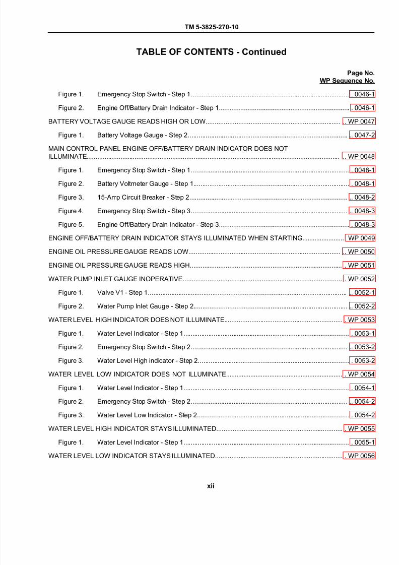
Figure 1. Emergency Stop Switch - Step 1.......................................................................................... 0046-1
Figure 2. Engine Off/Battery Drain Indicator - Step 1.......................................................................... 0046-1
BATTERY VOLTAGE GAUGE READS HIGH OR LOW............................................................................. WP 0047
Figure 1. Battery Voltage Gauge - Step 2........................................................................................... 0047-2
MAIN CONTROL PANEL ENGINE OFF/BATTERY DRAIN INDICATOR DOES NOT
ILLUMINATE................................................................................................................................................ WP 0048
Figure 1. Emergency Stop Switch - Step 1.......................................................................................... 0048-1
Figure 2. Battery Voltmeter Gauge - Step 1........................................................................................ 0048-1
Figure 3. 15-Amp Circuit Breaker - Step 2.......................................................................................... 0048-2
Figure 4. Emergency Stop Switch - Step 3.......................................................................................... 0048-3
Figure 5. Engine Off/Battery Drain Indicator - Step 3.......................................................................... 0048-3
ENGINE OFF/BATTERY DRAIN INDICATOR STAYS ILLUMINATED WHEN STARTING........................ WP 0049
ENGINE OIL PRESSURE GAUGE READS LOW....................................................................................... WP 0050
ENGINE OIL PRESSURE GAUGE READS HIGH...................................................................................... WP 0051
WATER PUMP INLET GAUGE INOPERATIVE.......................................................................................... WP 0052
Figure 1. Valve V1 - Step 1................................................................................................................. 0052-1
Figure 2. Water Pump Inlet Gauge - Step 2........................................................................................ 0052-2
WATER LEVEL HIGH INDICATOR DOES NOT ILLUMINATE................................................................... WP 0053
Figure 1. Water Level Indicator - Step 1.............................................................................................. 0053-1
Figure 2. Emergency Stop Switch - Step 2.......................................................................................... 0053-2
Figure 3. Water Level High indicator - Step 2...................................................................................... 0053-2
WATER LEVEL LOW INDICATOR DOES NOT ILLUMINATE.................................................................... WP 0054
Figure 1. Water Level Indicator - Step 1.............................................................................................. 0054-1
Figure 2. Emergency Stop Switch - Step 2.......................................................................................... 0054-2
Figure 3. Water Level Low Indicator - Step 2...................................................................................... 0054-2
WATER LEVEL HIGH INDICATOR STAYS ILLUMINATED....................................................................... WP 0055
Figure 1. Water Level Indicator - Step 1.............................................................................................. 0055-1
WATER LEVEL LOW INDICATOR STAYS ILLUMINATED........................................................................ WP 0056
TM 5-3825-270-10
xii

8/6/2019 TM 5-3825-270-10 ENGINEER MISSION MODULE WATER DISTRIBUTION
http://slidepdf.com/reader/full/tm-5-3825-270-10-engineer-mission-module-water-distribution 25/483
TABLE OF CONTENTS - Continued
Page No.
WP Sequence No.
Figure 1. Water Level Indicator - Step 1.............................................................................................. 0056-1
MANUAL WATER TURRET DOES NOT OPERATE.................................................................................. WP 0057
Figure 1. Valve V6 - Step 1................................................................................................................. 0057-1
Figure 2. Valve V1 - Step 2................................................................................................................. 0057-2
MANUAL WATER TURRET OUTPUT LOW............................................................................................... WP 0058
Figure 1. Valve V6 - Step 1................................................................................................................. 0058-1
Figure 2. Valve V1 - Step 2................................................................................................................. 0058-2
Figure 3. Valve V5 - Step 3................................................................................................................. 0058-3
GRAVITY FED SPRINKLER BAR DOES NOT OPERATE......................................................................... WP 0059
Figure 1. Valve V8 - Step 1................................................................................................................. 0059-1
GRAVITY FED SPRINKLER BAR STREAM LOW...................................................................................... WP 0060
Figure 1. Valve V8 - Step 1................................................................................................................. 0060-1
Figure 2. Gravity Fed Sprinkler Bar - Step 2....................................................................................... 0060-2
SPRINKLER HEADS DO NOT OPERATE.................................................................................................. WP 0061
SPRINKLER HEAD OUTPUT LOW............................................................................................................. WP 0062
Figure 1. Valve V1 - Step 3................................................................................................................. 0062-2
Figure 2. Valve V5 - Step 4................................................................................................................. 0062-3
WATER HOSE DOES NOT OPERATE....................................................................................................... WP 0063
Figure 1. Valve V1 - Step 1................................................................................................................. 0063-1
Figure 2. Valve V7 - Step 1................................................................................................................. 0063-2
Figure 3. Water Hose - Step 2............................................................................................................. 0063-2
Figure 4. Water Pump Outlet Gauge - Step 3..................................................................................... 0063-3
WATER HOSE OUTPUT LOW.................................................................................................................... WP 0064
Figure 1. Valve V1 - Step 1................................................................................................................. 0064-1
Figure 2. Valve V7 - Step 1................................................................................................................. 0064-2
Figure 3. Valve V5 - Step 2................................................................................................................. 0064-3
Figure 4. Water Hose - Step 3............................................................................................................. 0064-4
TM 5-3825-270-10
xiii

8/6/2019 TM 5-3825-270-10 ENGINEER MISSION MODULE WATER DISTRIBUTION
http://slidepdf.com/reader/full/tm-5-3825-270-10-engineer-mission-module-water-distribution 26/483
TABLE OF CONTENTS - Continued
Page No
WP Sequence No
Figure 5. Water Pump Outlet Gauge - Step 4..................................................................................... 0064-4
CAB CONTROL BOX ENGINE OFF/BATTERY DRAIN INDICATOR DOES NOT
ILLUMINATE................................................................................................................................................ WP 0065
Figure 1. Emergency Stop Switch - Step 1.......................................................................................... 0065-1
Figure 2. Engine Off/Battery Drain Indicator - Step 1.......................................................................... 0065-2
Figure 3. Emergency Stop Switch - Step 2.......................................................................................... 0065-2
Figure 4. Cab Control Box - Step 2..................................................................................................... 0065-3
Figure 5. UPIK Air And Electrical Connections - Step 2...................................................................... 0065-3
Figure 6. Emergency Stop Switch - Step 3.......................................................................................... 0065-4
Figure 7. Cab Control Box Engine Off/Battery Drain Indicator - Step 3............................................... 0065-4
CAB CONTROL BOX TACHOMETER DOES NOT OPERATE.................................................................. WP 0066
Figure 1. Tachometer - Step 1............................................................................................................. 0066-1
Figure 2. Cab Control Box - Step 2..................................................................................................... 0066-2
Figure 3. UPIK Air And Electrical Connections - Step 2...................................................................... 0066-2
Figure 4. Cab Control Box Tachometer - Step 3................................................................................. 0066-3
CAB CONTROL BOX WATER LEVEL HIGH INDICATOR DOES NOT ILLUMINATE........... .................... WP 0067
Figure 1. Emergency Stop Switch - Step 1.......................................................................................... 0067-1
Figure 2. Water Level High indicator - Step 1...................................................................................... 0067-2
Figure 3. Cab Control Box - Step 2..................................................................................................... 0067-2
Figure 4. UPIK Air And Electrical Connections - Step 2...................................................................... 0067-3
Figure 5. Emergency Stop Switch - Step 3.......................................................................................... 0067-3
Figure 6. Cab Control Box Water Level High Indicator - Step 3.......................................................... 0067-4
CAB CONTROL BOX WATER LEVEL LOW INDICATOR DOES NOT ILLUMINATE............... ................. WP 0068
Figure 1. Emergency Stop Switch - Step 1.......................................................................................... 0068-1
Figure 2. Water Level Low Indicator - Step 1...................................................................................... 0068-2
Figure 3. Cab Control Box - Step 2..................................................................................................... 0068-2
Figure 4. UPIK Air And Electrical Connections - Step 2...................................................................... 0068-3
Figure 5. Emergency Stop Switch - Step 3.......................................................................................... 0068-3
TM 5-3825-270-10
xiv
8/6/2019 TM 5-3825-270-10 ENGINEER MISSION MODULE WATER DISTRIBUTION
http://slidepdf.com/reader/full/tm-5-3825-270-10-engineer-mission-module-water-distribution 27/483
TABLE OF CONTENTS - Continued
Page No.
WP Sequence No.
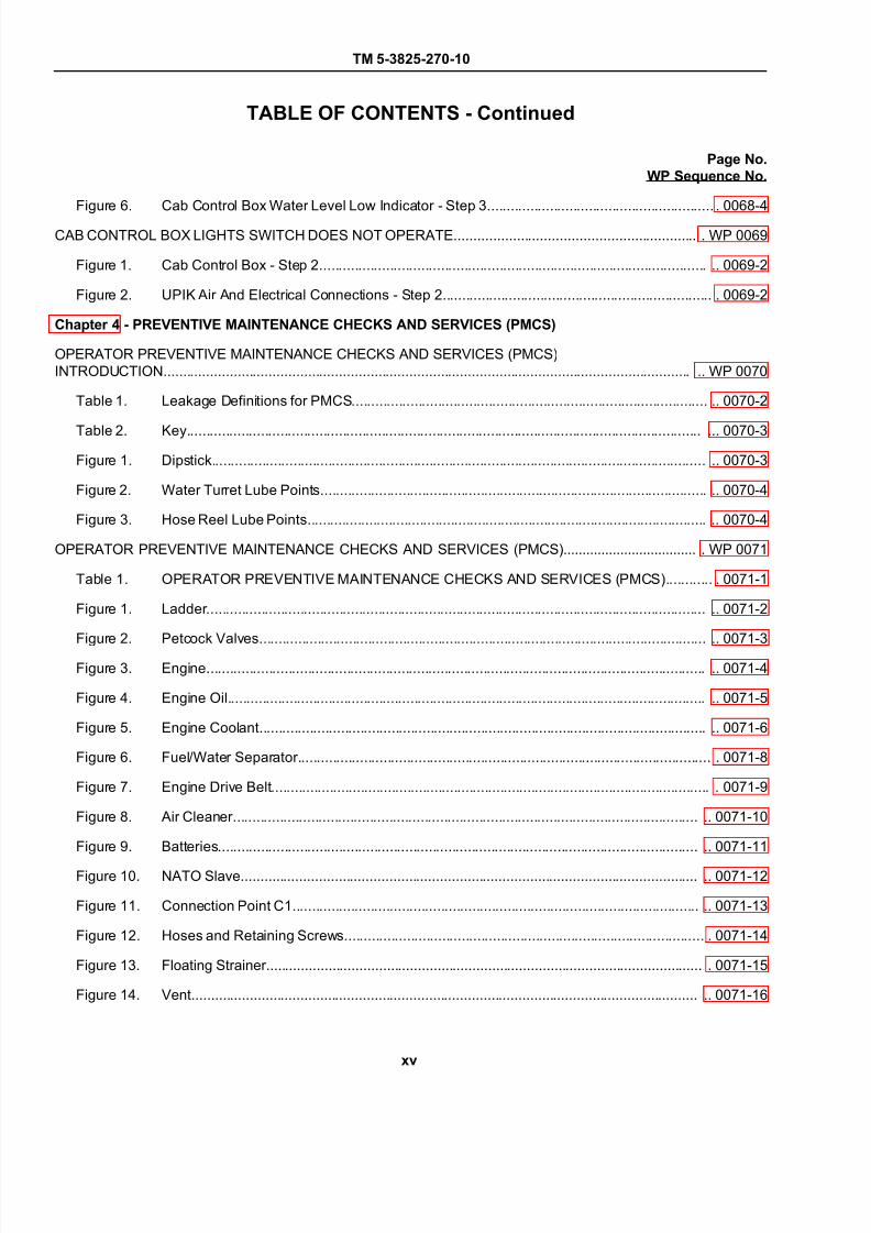
Figure 6. Cab Control Box Water Level Low Indicator - Step 3........................................................... 0068-4
CAB CONTROL BOX LIGHTS SWITCH DOES NOT OPERATE............................................................... WP 0069
Figure 1. Cab Control Box - Step 2..................................................................................................... 0069-2
Figure 2. UPIK Air And Electrical Connections - Step 2...................................................................... 0069-2
Chapter 4 - PREVENTIVE MAINTENANCE CHECKS AND SERVICES (PMCS)
OPERATOR PREVENTIVE MAINTENANCE CHECKS AND SERVICES (PMCS)
INTRODUCTION......................................................................................................................................... WP 0070
Table 1. Leakage Definitions for PMCS............................................................................................. 0070-2
Table 2. Key....................................................................................................................................... 0070-3
Figure 1. Dipstick................................................................................................................................. 0070-3
Figure 2. Water Turret Lube Points..................................................................................................... 0070-4
Figure 3. Hose Reel Lube Points......................................................................................................... 0070-4
OPERATOR PREVENTIVE MAINTENANCE CHECKS AND SERVICES (PMCS).................................... WP 0071
Table 1. OPERATOR PREVENTIVE MAINTENANCE CHECKS AND SERVICES (PMCS)............. 0071-1
Figure 1. Ladder.................................................................................................................................. 0071-2
Figure 2. Petcock Valves..................................................................................................................... 0071-3
Figure 3. Engine.................................................................................................................................. 0071-4
Figure 4. Engine Oil............................................................................................................................. 0071-5
Figure 5. Engine Coolant..................................................................................................................... 0071-6
Figure 6. Fuel/Water Separator........................................................................................................... 0071-8
Figure 7. Engine Drive Belt.................................................................................................................. 0071-9
Figure 8. Air Cleaner......................................................................................................................... 0071-10
Figure 9. Batteries............................................................................................................................. 0071-11
Figure 10. NATO Slave....................................................................................................................... 0071-12
Figure 11. Connection Point C1.......................................................................................................... 0071-13
Figure 12. Hoses and Retaining Screws............................................................................................. 0071-14
Figure 13. Floating Strainer................................................................................................................. 0071-15
Figure 14. Vent.................................................................................................................................... 0071-16
TM 5-3825-270-10
xv

8/6/2019 TM 5-3825-270-10 ENGINEER MISSION MODULE WATER DISTRIBUTION
http://slidepdf.com/reader/full/tm-5-3825-270-10-engineer-mission-module-water-distribution 28/483
TABLE OF CONTENTS - Continued
Page No
WP Sequence No
Figure 15. Tank................................................................................................................................... 0071-16
Figure 16. Water Level Indicator......................................................................................................... 0071-17
Figure 17. Fuel Tank........................................................................................................................... 0071-19
Figure 18. UPIK Interface Kit............................................................................................................... 0071-20
Figure 19. Stowage Box...................................................................................................................... 0071-21
Figure 20. Fire Extinguisher................................................................................................................ 0071-23
Figure 21. Safety Chain....................................................................................................................... 0071-24
Figure 22. Folding Handrail................................................................................................................. 0071-25
Figure 23. Control Box......................................................................................................................... 0071-26
Figure 24. Water Turret....................................................................................................................... 0071-27
Figure 25. Manhole Cover................................................................................................................... 0071-28
Figure 26. Hose Reel........................................................................................................................... 0071-29
Figure 27. Sprinklers........................................................................................................................... 0071-30
Figure 28. Air Oiler.............................................................................................................................. 0071-31
Figure 29. Air Actuators....................................................................................................................... 0071-32
Figure 30. Sprinkler Bar....................................................................................................................... 0071-33
Figure 31. Work Lights........................................................................................................................ 0071-34
Figure 32. Engine................................................................................................................................ 0071-35
Figure 33. Exhaust System................................................................................................................. 0071-36
Figure 34. Controls and Indicators...................................................................................................... 0071-37
Figure 35. Safety Chain....................................................................................................................... 0071-38
Figure 36. Work Lights........................................................................................................................ 0071-39
Figure 37. Sprinklers........................................................................................................................... 0071-40
Figure 38. Hose Reel........................................................................................................................... 0071-41
Figure 39. Sprinkler Bar....................................................................................................................... 0071-42
Figure 40. Engine................................................................................................................................ 0071-43
Figure 41. Air Filter Restriction Indicator............................................................................................. 0071-44
TM 5-3825-270-10
xvi

8/6/2019 TM 5-3825-270-10 ENGINEER MISSION MODULE WATER DISTRIBUTION
http://slidepdf.com/reader/full/tm-5-3825-270-10-engineer-mission-module-water-distribution 29/483
TABLE OF CONTENTS - Continued
Page No.
WP Sequence No.
Figure 42. Engine Oil Level................................................................................................................. 0071-45
Figure 43. Hoses and Connection Point Covers................................................................................. 0071-46
Figure 44. Floating Strainer................................................................................................................. 0071-47
Figure 45. Tank................................................................................................................................... 0071-48
Figure 46. Fuel Tank........................................................................................................................... 0071-50
Figure 47. UPIK Interface Kit............................................................................................................... 0071-51
Figure 48. Stowage Box...................................................................................................................... 0071-52
Figure 49. Ladder................................................................................................................................ 0071-53
Figure 50. Hose Reel........................................................................................................................... 0071-54
Figure 51. Sprinklers........................................................................................................................... 0071-55
Figure 52. Rollers................................................................................................................................ 0071-56
Figure 53. Sprinkler Bar....................................................................................................................... 0071-57
Figure 54. Exhaust System................................................................................................................. 0071-58
Figure 55. Batteries............................................................................................................................. 0071-59
Figure 56. Fuel Tank........................................................................................................................... 0071-61
Figure 57. UPIK Interface Kit............................................................................................................... 0071-62
Figure 58. Stowage Box...................................................................................................................... 0071-63
Figure 59. Air Filter.............................................................................................................................. 0071-64
Figure 60. Sheet Metal and Frame...................................................................................................... 0071-65
Figure 61. Air Lines, Hoses, and Wiring.............................................................................................. 0071-66
Figure 62. Valves and Connection Point Covers................................................................................. 0071-67
Chapter 5 - MAINTENANCE INSTRUCTIONS
SERVICE UPON RECEIPT......................................................................................................................... WP 0072
BACK FLUSHING........................................................................................................................................ WP 0073
Figure 1. Back Flushing....................................................................................................................... 0073-1
PREPARATION FOR TRANSPORT........................................................................................................... WP 0074
Figure 1. Preparation For Highway, Rail, Or Fixed Wing Air Transport............................................... 0074-2
TM 5-3825-270-10
xvii

8/6/2019 TM 5-3825-270-10 ENGINEER MISSION MODULE WATER DISTRIBUTION
http://slidepdf.com/reader/full/tm-5-3825-270-10-engineer-mission-module-water-distribution 30/483
TABLE OF CONTENTS - Continued
Page No
WP Sequence No
Figure 2. Preparation For Highway, Rail, Or Fixed Wing Air Transport............................................... 0074-2
Figure 3. Placing Water Distributor Back In Service After Highway, Rail, Or Fixed Wing
Air Transport......................................................................................................................... 0074-3
Figure 4. Placing Water Distributor Back In Service After Highway, Rail, Or Fixed Wing
Air Transport......................................................................................................................... 0074-3
STOW/UNSTOW ROLLERS....................................................................................................................... WP 0075
Figure 1. Stow Rollers......................................................................................................................... 0075-1
Figure 2. Unstow Rollers..................................................................................................................... 0075-2
STOW\UNSTOW LADDER.......................................................................................................................... WP 0076
Figure 1. Unstow Ladder..................................................................................................................... 0076-1
Figure 2. Unstow Ladder..................................................................................................................... 0076-2
Figure 3. Stow Ladder......................................................................................................................... 0076-2
Figure 4. Stow Ladder......................................................................................................................... 0076-3
STOW/UNSTOW RAILING.......................................................................................................................... WP 0077
Figure 1. Stow Railing......................................................................................................................... 0077-1
Figure 2. Stow Railing......................................................................................................................... 0077-2
Figure 3. Stow Railing......................................................................................................................... 0077-2
Figure 4. Unstow Railing..................................................................................................................... 0077-3
Figure 5. Unstow Railing..................................................................................................................... 0077-3
Figure 6. Unstow Railing..................................................................................................................... 0077-4
STOW/UNSTOW HOSES............................................................................................................................ WP 0078
Figure 1. Unstow Fill Hoses................................................................................................................. 0078-1
Figure 2. Stow Fill Hoses..................................................................................................................... 0078-2
Figure 3. Unwind Hose Reel................................................................................................................ 0078-2
Figure 4. Unwind Hose Reel................................................................................................................ 0078-3
Figure 5. Retract Hose Reel................................................................................................................ 0078-3
Figure 6. Retract Hose Reel................................................................................................................ 0078-4
Figure 7. Retract Hose Reel................................................................................................................ 0078-4
TM 5-3825-270-10
xviii

8/6/2019 TM 5-3825-270-10 ENGINEER MISSION MODULE WATER DISTRIBUTION
http://slidepdf.com/reader/full/tm-5-3825-270-10-engineer-mission-module-water-distribution 31/483
TABLE OF CONTENTS - Continued
Page No.
WP Sequence No.
STOW/UNSTOW FLOATING STRAINER................................................................................................... WP 0079
Figure 1. Unstow Floating Strainer...................................................................................................... 0079-1
Figure 2. Stow Floating Strainer.......................................................................................................... 0079-2
OPEN/CLOSE MANHOLE COVER............................................................................................................. WP 0080
Figure 1. Open Manhole Cover........................................................................................................... 0080-1
Figure 2. Close Manhole Cover........................................................................................................... 0080-2
OPEN/CLOSE BATTERY BOX................................................................................................................... WP 0081
Figure 1. Open Battery Box................................................................................................................. 0081-1
Figure 2. Close Battery Box................................................................................................................. 0081-2
OPEN/CLOSE ENGINE ACCESS COVERS............................................................................................... WP 0082
Figure 1. Open Engine Access Cover................................................................................................. 0082-1
Figure 2. Close Engine Access Cover................................................................................................. 0082-2
CLEANING................................................................................................................................................. .. WP 0083
DATA PLATES AND STENCILS................................................................................................................. WP 0084
Figure 1. Data Plates........................................................................................................................... 0084-1
Figure 2. Data Plates........................................................................................................................... 0084-1
Figure 3. Data Plates........................................................................................................................... 0084-2
Figure 4. Stencils................................................................................................................................. 0084-2
Figure 5. Stencils................................................................................................................................. 0084-3
Figure 6. Stencils................................................................................................................................. 0084-4
Figure 7. Stencils................................................................................................................................. 0084-5
Figure 8. Stencils................................................................................................................................. 0084-6
Figure 9. Stencils................................................................................................................................. 0084-7
Figure 10. Stencils................................................................................................................................. 0084-8
Figure 11. Stencils................................................................................................................................. 0084-9
Figure 12. Stencils................................................................................................................................. 0084-9
OUTER AIR FILTER ELEMENT REMOVAL/SERVICE/INSTALLATION.................................................... WP 0085
TM 5-3825-270-10
xix

8/6/2019 TM 5-3825-270-10 ENGINEER MISSION MODULE WATER DISTRIBUTION
http://slidepdf.com/reader/full/tm-5-3825-270-10-engineer-mission-module-water-distribution 32/483
TABLE OF CONTENTS - Continued
Page No
WP Sequence No
Figure 1. Air Filter Element Removal................................................................................................... 0085-1
Figure 2. Air Filter Element Removal................................................................................................... 0085-2
Figure 3. Air Filter Element Service..................................................................................................... 0085-2
Figure 4. Air Filter Element Service..................................................................................................... 0085-3
Figure 5. Air Filter Element Installation................................................................................................ 0085-4
Figure 6. Air Filter Element Installation................................................................................................ 0085-4
Figure 7. Air Filter Element Installation................................................................................................ 0085-5
Chapter 6 - SUPPORTING INFORMATION
REFERENCES............................................................................................................................................ WP 0086
COMPONENTS OF END ITEM AND BASIC ISSUE ITEMS LISTS............................................................ WP 0087
Table 1. COMPONENTS OF END ITEM........................................................................................... 0087-2
Table 2. BASIC ISSUE ITEMS........................................................................................................... 0087-3
EXPENDABLE/DURABLE ITEMS LIST...................................................................................................... WP 0088
FO1 DATA PLATE....................................................................................................................................... WP 0089
Foldout Figures
FO-1. Data Plate........................................................................................................................................... FP-1
TM 5-3825-270-10
xx

8/6/2019 TM 5-3825-270-10 ENGINEER MISSION MODULE WATER DISTRIBUTION
http://slidepdf.com/reader/full/tm-5-3825-270-10-engineer-mission-module-water-distribution 33/483
HOW TO USE THIS MANUAL
GENERAL INFORMATION
This manual is designed to help operate and maintain the Water Distributor, NSN 3825-01-577-2713, Part Numbe
5251894. Listed below are some of the features included in this manual to help locate and use the needed
information:
• Warning, caution and note headings, subject headings and other essential information are printed in bold
type, making them easier to see.
• In addition to text, there are digital photos and some line art illustrations showing how to take a componen
off and put it back on. Cleaning and inspection criteria are also included where necessary.
• Chapter 1 of this manual covers General Information, Equipment Description and Data, and Theory of
Operation.
• Chapter 2 of this manual covers Operator Instructions.
• Chapter 3 of this manual provides an Introduction to Troubleshooting and Troubleshooting Procedures.
• Chapter 4 of this manual covers Preventive Maintenance Checks and Services (PMCS).
• Chapter 5 of this manual covers Maintenance Instructions.• Chapter 6 of this manual provides Supporting Information, References, Components of End Item and Bas
Issue Items, and Expendables/Durable Supplies and Materials List.
Follow these guidelines when using this manual:
• Read all WARNINGS, CAUTIONS, and NOTES prior to performing any procedure.
• The operator must read through this manual and become familiar with its contents before attempting to
operate the Water Distributor.
• Water Distributor TM 5-3825-270-10 is used in conjunction with Palletized Load System (PLS) TM
9-2320-364 manual series.
TM 5-3825-270-10
xxi/xxii blank

8/6/2019 TM 5-3825-270-10 ENGINEER MISSION MODULE WATER DISTRIBUTION
http://slidepdf.com/reader/full/tm-5-3825-270-10-engineer-mission-module-water-distribution 34/483

8/6/2019 TM 5-3825-270-10 ENGINEER MISSION MODULE WATER DISTRIBUTION
http://slidepdf.com/reader/full/tm-5-3825-270-10-engineer-mission-module-water-distribution 35/483
CHAPTER 1
GENERAL INFORMATION, EQUIPMENT DESCRIPTION, AND
THEORY OF OPERATION
TM 5-3825-270-10

8/6/2019 TM 5-3825-270-10 ENGINEER MISSION MODULE WATER DISTRIBUTION
http://slidepdf.com/reader/full/tm-5-3825-270-10-engineer-mission-module-water-distribution 36/483

8/6/2019 TM 5-3825-270-10 ENGINEER MISSION MODULE WATER DISTRIBUTION
http://slidepdf.com/reader/full/tm-5-3825-270-10-engineer-mission-module-water-distribution 37/483
OPERATOR MAINTENANCEGENERAL INFORMATION
SCOPE
TYPE OF MANUAL
This manual contains operation and operator maintenance instructions for the Engineer Mission Module - Water Distributor (EMM - WD).
EQUIPMENT NAME AND MODEL NUMBER
Engineer Mission Module - Water Distributor (EMM - WD), NSN 3825-01-577-2713, the module is manufactured bE.D. Etnyre and Co.
PURPOSE OF EQUIPMENT
The EMM - WD's primary mission is to enhance the engineer corps and supported forces in the areas of combatsupport, combat service support and general construction; this includes the construction of airfields, railways, roadand infrastructure. When mounted on a truck or trailer the Engineer Mission Module - Water Distributor (EMM - WDshall provide a means of:
• Spreading measured amounts of water for increasing soil moisture• Applying soil stabilization additives• Applying dust control chemicals• Firefighting support capability
MAINTENANCE FORMS AND RECORDS
Department of the Army forms and procedures used for equipment maintenance will be those prescribed by DAPAM 750-8, The Army Maintenance Management System (TAMMS) Users Manual (WP 0086).
REPORTING EQUIPMENT IMPROVEMENT RECOMMENDATIONS (EIR)
If your Engineer Mission Module - Water Distributor (EEM-WD) needs improvement, let us know. Send us an EIR.You, the user, are the only one who can tell us what you don’t like about your equipment. Let us know why you dolike the design or performance. If you have internet access, the easiest and fastest way to report problem or suggestions is to go to https://aeps.ria.army.mil/aepspublic.cfm (scroll down and choose the "Submit QualityDeficiency Report" bar). The Internet form lets you choose to submit an Equipment Improvement Recommendatio(EIR), a Product Quality Deficiency Report (PQDR) or a Warranty Claim Action (WCA). You may also submit yourinformation using an SF 368 (Product Quality Deficiency Report)(WP 0086) . You can send your SF 368 via e-mairegular mail, or facsimile using the addresses/facsimile numbers specified in DA PAM 750-8, The Army MaintenanManagement System (TAMMS) Users Manual (WP 0086). We will send you a reply.
CORROSION PREVENTION AND CONTROL (CPC)
Corrosion Prevention and Control (CPC) of Army materiel is a continuing concern. It is important that any corrosioproblems with the Engineer Mission Module - Water Distributor (EMM - WD) be reported so that the problem can bcorrected and improvements can be made to prevent the problem in the future. While corrosion is typically associawith rusting of metals, corrosion can also include deterioration of other materials, such as rubber and plastic. Unuscracking, softening, swelling, or breaking of these materials may be a corrosion problem. If a corrosion problem isidentified, it can be reported using a SF 368 (Product Quality Deficiency Report) (WP 0086) which should besubmitted to the address specified in DA PAM 750-8, The Army Maintenance Management System (TAMMS) UseManual (WP 0086).
TM 5-3825-270-10 0001
0001-1

8/6/2019 TM 5-3825-270-10 ENGINEER MISSION MODULE WATER DISTRIBUTION
http://slidepdf.com/reader/full/tm-5-3825-270-10-engineer-mission-module-water-distribution 38/483
DESTRUCTION OF ARMY MATERIAL TO PREVENT ENEMY USE
Command decision, according to the tactical situation, will determine when the destruction of the Engineer MissionModule - Water Distributor (EMM - WD) will be accomplished. A destruction plan will be prepared by the usingorganization unless one has been prepared by a higher authority. For general destruction procedures for thisequipment, refer to TM 750-244-6, Procedures for Destruction of Tank-Automotive Equipment to Prevent EnemyUse (U.S. Army Tank-automotive and Armaments Command) (WP 0086).
WARRANTY INFORMATION
The Water Distributor is warranted for a period of twelve (12) months from the date of warranty activation. Thewarranty starts when the Water Distributor's warranty data plate is stamped by the Contractor during the Water Distributor hand-off. Report all defects to your supervisor, who will take appropriate action. For equipment under manufacturer's warranty, hard time oil service intervals shall be followed. Intervals shall be shortened if lubricantsare known to be contaminated or if operation is under adverse conditions, such as longer than usual operating hours,extended idling period, or extreme dust.
LIST OF ABBREVIATIONS
This list consists of special or unique abbreviations, acronyms, and descriptors not contained in MIL-STD-12,Abbreviations for use on Drawings, and in Specifications, Standards and Technical Documents (WP 0086)
Table 1. List of Abbreviations.
amp Amperes
BII Basic Issue Item
C Centigrade
CAGEC Commercial and Government Entity Code
cm Centimeter
COEI Components of End Item
CTA Common Table of Allowances
DA Department of the Army
DC Direct Current
EIR Equipment Improvement Recommendation
EMM - WD Engineer Mission Module - Water Distributor
F Fahrenheit
ft Foot
GPM Gallons per Minute
hp Horsepower
TM 5-3825-270-10 0001
0001-2

8/6/2019 TM 5-3825-270-10 ENGINEER MISSION MODULE WATER DISTRIBUTION
http://slidepdf.com/reader/full/tm-5-3825-270-10-engineer-mission-module-water-distribution 39/483
LIST OF ABBREVIATIONS - Continued
Table 1. List of Abbreviations - Continued.
in. Inch
ISO International Standards Organization
kPa Kilopascal
L Liter
lb Pound
LHS Load Handling System
m Meter
ml Milliliters
mm Millimeter
NBC Nuclear, Biological, Chemical
NSN National Stock Number
PLS Palletized Load System
PLST Palletized Load System Trailer
PMCS Preventive Maintenance Checks and Services
PQDR Product Quality Deficiency Report
psi Pound-Force Per Square Inch
Qt Quart
RPSTL Repair Parts and Special Tools List
rpm Revolutions Per Minute
SAE Society of Automotive Engineers
STD Standard
TAMMS The Army Maintenance Management System
TM Technical Manual
U/I Unit Of Issue
U/M Unit Of Measure
TM 5-3825-270-10 0001
0001-3

8/6/2019 TM 5-3825-270-10 ENGINEER MISSION MODULE WATER DISTRIBUTION
http://slidepdf.com/reader/full/tm-5-3825-270-10-engineer-mission-module-water-distribution 40/483
LIST OF ABBREVIATIONS - Continued
Table 1. List of Abbreviations - Continued.
vdc Volts Direct Current
WCA Warranty Claim Action
SAFETY
GENERAL
Even though the Engineer Mission Module - Water Distributor (EMM - WD) has no special hazardous or dangerouscharacteristics during exposure to normal transportation environments, several general safety considerations andprecautions are important.
• Check the entire module to be sure loose items are properly secured.• Have fire extinguishers readily available when operating the Engineer Mission Module - Water Distributor
(EMM - WD).• Make sure only qualified personnel operate the Engineer Mission Module - Water Distributor (EMM - WD).
• Do not leave the Engineer Mission Module - Water Distributor (EMM - WD) unattended while the engine isrunning.
• Do not operate the Engineer Mission Module - Water Distributor (EMM - WD) on public roads without theappropriate safety equipment.
• Adhere to all local, state, federal, and host-nation safety laws and regulations applying to commercialcarriers.
WARNING ICONS
Table 2. Warning Icons.
EAR PROTECTION - headphones over ears shows thatnoise level will harm ears.
ELECTRICAL - electrical wire to arm with electricitysymbol running through human body shows that shockhazard is present.
ELECTRICAL - electrical wire to hand with electricity
symbol running through hand shows that shock hazardis present.
TM 5-3825-270-10 0001
0001-4

8/6/2019 TM 5-3825-270-10 ENGINEER MISSION MODULE WATER DISTRIBUTION
http://slidepdf.com/reader/full/tm-5-3825-270-10-engineer-mission-module-water-distribution 41/483
WARNING ICONS - Continued
Table 2. Warning Icons - Continued.
FALLING PARTS - arrow bouncing off human shoulder and head shows that falling parts present a danger to lif
or limb.
FLYING PARTICLES - arrows bouncing off face showsthat particles flying through the air will harm face.
FLYING PARTICLES - arrows bouncing off face with
face shield shows that particles flying through the air wilharm face.
HEAVY OBJECT - human figure stooping over heavyobject shows physical injury potential from improper lifting technique.
HEAVY PARTS - hand with heavy object on top showsthat heavy parts can crush and harm.
HEAVY PARTS - foot with heavy object on top showsthat heavy parts can crush and harm.
HEAVY PARTS - heavy object on human figure showsthat heavy parts present a danger to life or limb.
TM 5-3825-270-10 0001
0001-5

8/6/2019 TM 5-3825-270-10 ENGINEER MISSION MODULE WATER DISTRIBUTION
http://slidepdf.com/reader/full/tm-5-3825-270-10-engineer-mission-module-water-distribution 42/483
WARNING ICONS - Continued
Table 2. Warning Icons - Continued.
HEAVY PARTS - heavy object pinning human figureagainst wall shows that heavy, moving parts present a
danger to life or limb.
HELMET PROTECTION - arrow bouncing off head withhelmet shows that falling parts present a danger.
HOT AREA - hand over object radiating heat shows that
part is hot and can burn.
LASER LIGHT - laser light hazard symbol indicatesextreme danger for eyes from laser beams andreflections.
MOVING PARTS - human figure with an arm caughtbetween gears shows that the moving parts of theequipment present a danger to life or limb.
MOVING PARTS - hand with fingers caught betweengears shows that the moving parts of the equipmentpresent a danger to life or limb.
MOVING PARTS - hand with fingers caught betweenrollers shows that the moving parts of the equipmentpresent a danger to life or limb.
TM 5-3825-270-10 0001
0001-6

8/6/2019 TM 5-3825-270-10 ENGINEER MISSION MODULE WATER DISTRIBUTION
http://slidepdf.com/reader/full/tm-5-3825-270-10-engineer-mission-module-water-distribution 43/483
WARNING ICONS - Continued
Table 2. Warning Icons - Continued.
SHARP OBJECT - pointed object in hand shows that asharp object presents a danger to limb.
SHARP OBJECT - pointed object in hand shows that asharp object presents a danger to limb.
SHARP OBJECT - pointed object in foot shows that a
sharp object presents a danger to limb.
SLICK FLOOR - wavy line on floor with legs prone showthat slick floor presents a danger for falling.
BIOLOGICAL - abstract symbol bug shows that amaterial may contain bacteria or viruses that present adanger to life or health.
CHEMICAL - drops of liquid on hand shows that thematerial will cause burns or irritation to human skin or tissue.
CRYOGENIC - hand in block of ice shows that thematerial is extremely cold and can injure human skin or tissue.
TM 5-3825-270-10 0001
0001-7

8/6/2019 TM 5-3825-270-10 ENGINEER MISSION MODULE WATER DISTRIBUTION
http://slidepdf.com/reader/full/tm-5-3825-270-10-engineer-mission-module-water-distribution 44/483
WARNING ICONS - Continued
Table 2. Warning Icons - Continued.
EXPLOSION - rapidly expanding symbol shows that thematerial may explode if subjected to high temperatures,sources of ignition or high pressure.
EYE PROTECTION - person with goggles shows thatthe material will injure the eyes.
FIRE - flame shows that a material may ignite and cause
burns.
POISON - skull and crossbones shows that a material ispoisonous or is a danger to life.
RADIATION - three circular wedges shows that thematerial emits radioactive energy and can injure humantissue.
VAPOR - human figure in a cloud shows that materialvapors present a danger to life or health.
END OF WORK PACKAGE
TM 5-3825-270-10 0001
0001-8

8/6/2019 TM 5-3825-270-10 ENGINEER MISSION MODULE WATER DISTRIBUTION
http://slidepdf.com/reader/full/tm-5-3825-270-10-engineer-mission-module-water-distribution 45/483
OPERATOR MAINTENANCEEQUIPMENT DESCRIPTION AND DATA
GENERAL
The Engineer Mission Module - Water Distributor (EMM - WD) is a demountable 3000 gallon unit for use with NATSTANAG compatible Load Handling System (LHS) type trucks (e.g., PLS M1075) and associated trailers (e.g., PLM1076). The Engineer Mission Module - Water Distributor (EMM - WD) is compatible for PLS transport, operationand use throughout the mission profile. It can also be powered by an on-board diesel engine. The Engineer MissioModule - Water Distributor (EMM - WD) when unloaded from the PLS truck is capable of operating as a wash rackfacility. The Water Distributor can be operated from the cab of the PLS vehicle when vehicle is moving or at the recontrol station when vehicle is not moving. It is composed of a 3,000 gallon stainless steel water tank mounted ontop of a slightly modified M1077 flatrack. Internal baffles in the tank minimize sloshing of material during operationA 20 inch manhole is located at the rear top of the tank to permit access for inspection or filling. A catwalk and hanrails are provided to allow access to the manhole from the rear control station. An overflow pipe, located at the topof the tank, was incorporated to prevent overfilling and to allow room for expansion of the material. A drain is locatin the bottom rear of the tank for complete draining of the unit for service or inspection. Several inlet/outlet ports aprovided with a variety of adapters for various connections and operations. The EMM - WD is intended for fresh
water operation only; saltwater shall not be used in the EMM - WD.
EQUIPMENT DATA
Refer to the following table for specific equipment data.
Table 1. Equipment Data.
Item Specification
TANK RACK
Tank Capacity (usable) 3,000 gal
NSN 3825-01-577-2713
Part Number 5251894
Model Number WD3000
Length 238.4"
Width 96"
Height 82.1"
Weight, Empty 8,500 lb
Weight, Full 33,500 lb
WATER PUMP
Type Self-Priming Centrifugal
Nominal Capacity 600 gpm
TM 5-3825-270-10 0002
0002-1

8/6/2019 TM 5-3825-270-10 ENGINEER MISSION MODULE WATER DISTRIBUTION
http://slidepdf.com/reader/full/tm-5-3825-270-10-engineer-mission-module-water-distribution 46/483
EQUIPMENT DATA - Continued
Table 1. Equipment Data - Continued.
Item Specification
Drive Direct with engine flywheel flex coupling
Minimum Recommended Operating Speed 1500 Engine rpm (continuous)
Maximum Recommended Operating Speed 2400 Engine rpm (continuous)
Maximum Discharge Pressure (outlet blocked) 135 psi at 2400 Engine rpm (30 seconds maximum)
ENGINE
Type Naturally Aspirated Liquid Cooled Diesel
Model Kubota V3600–E3B
Power 66.8 HP
Maximum Speed 2400 rpm
Low Idle Speed 1000 rpm
WATER TURRET
Spray Distance Capability over 175' (shaper nozzle) over 125' (fog nozzle)
Normal Operation Output (shaper nozzle) 2400 Engine rpm: 110psi, 550 gpm
SPRINKLER NOZZLES
Type (2) Fan Nozzles-Adjustable Direction Fixed Opening
Spray Width Capability 80'
Normal Operation Output (one nozzle) 1800 Engine rpm: 75 psi, 235 gpm
Normal Operation Output (two nozzles) 1800 Engine rpm: 65 psi, 420 gpm
Full Output (two nozzles) 2400 Engine rpm: 110 psi, 550 gpm
HOSE REEL
Type Manual Crank
Hose Size 1.5" x 50'
Normal Operation Output (full open nozzle) 1500 Engine rpm: 50 psi, 65 gpm
Full Output (full open nozzle) 2400 Engine rpm: 125 psi, 110 gpm
TM 5-3825-270-10 0002
0002-2
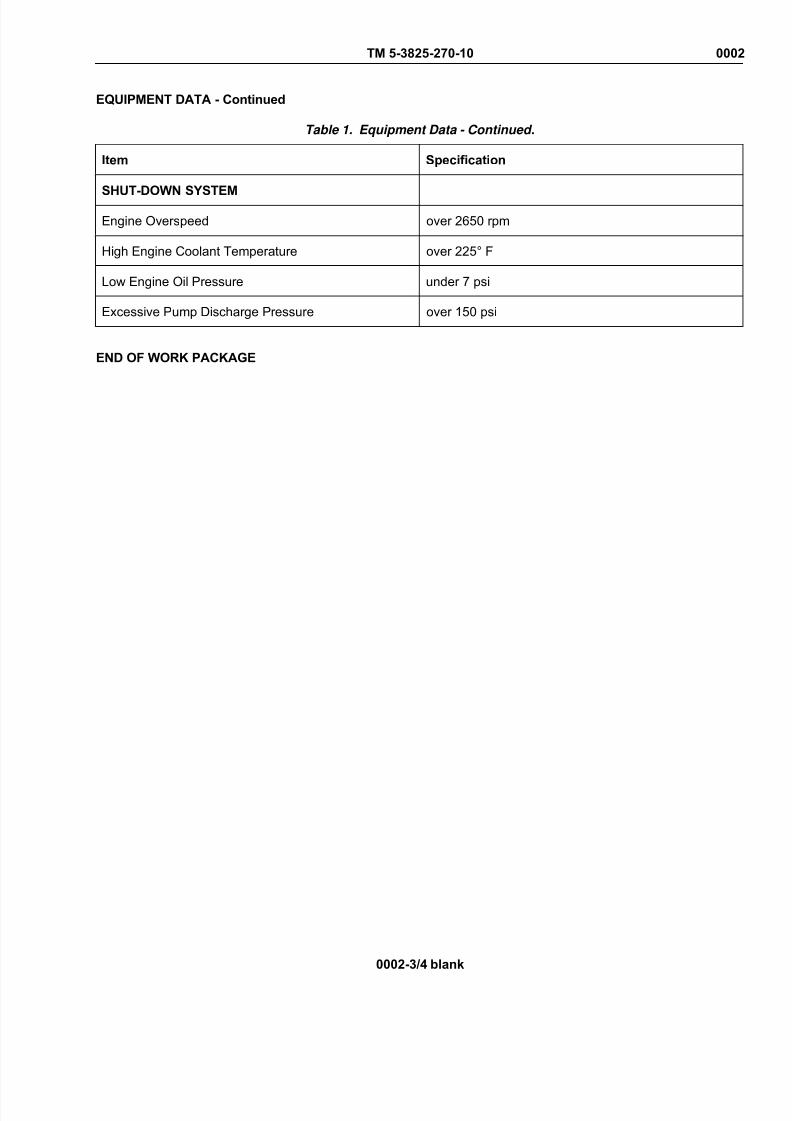
8/6/2019 TM 5-3825-270-10 ENGINEER MISSION MODULE WATER DISTRIBUTION
http://slidepdf.com/reader/full/tm-5-3825-270-10-engineer-mission-module-water-distribution 47/483
EQUIPMENT DATA - Continued
Table 1. Equipment Data - Continued.
Item Specification
SHUT-DOWN SYSTEM
Engine Overspeed over 2650 rpm
High Engine Coolant Temperature over 225° F
Low Engine Oil Pressure under 7 psi
Excessive Pump Discharge Pressure over 150 psi
END OF WORK PACKAGE
TM 5-3825-270-10 0002
0002-3/4 blank

8/6/2019 TM 5-3825-270-10 ENGINEER MISSION MODULE WATER DISTRIBUTION
http://slidepdf.com/reader/full/tm-5-3825-270-10-engineer-mission-module-water-distribution 48/483

8/6/2019 TM 5-3825-270-10 ENGINEER MISSION MODULE WATER DISTRIBUTION
http://slidepdf.com/reader/full/tm-5-3825-270-10-engineer-mission-module-water-distribution 49/483
OPERATOR MAINTENANCETHEORY OF OPERATION
INTRODUCTION
The EMM - WD's primary mission is to enhance the engineer corps and supported forces in the areas of combatsupport, combat service support and general construction; this includes the construction of airfields, railways, roadand infrastructure.
PRINCIPLES OF OPERATION
Electrical power is provided to the module by on-board systems. Water distribution is accomplished through the horeel, sprinkler system, water turret, and gravity bar.
OPERATIONAL FEATURES OF COMPONENTS
ENGINE
The engine, which powers the pump, is mounted within the module unit. It receives its fuel from a 20 gal (76 L) fuetank mounted to the flatrack on the front left side. Control of the engine is by the control panel as described below
The EMM - WD and the engine is not shielded against electromagnetic interference. A standoff from high frequen
communications is recommended.
PUMP
The pump is coupled directly to the engine. The purpose of the pump is to pump water out of or into the tank.
VALVES
There are a total of eight valves on the Water Distributor that control different operations. Refer to data plates and
decals (WP 0084) for location of valves.
CONTROL PANEL
The control panel controls the starting and stopping of the engine. It also monitors the tank functions as well as thehigh and low water indicators. The control panel is permanently mounted on the rear platform.
TRANSPORTER OPERATION AND FUNCTIONS
For transporter operation and functions refer to: TM 9-2320-364-10 for the Palletized Load System (PLS) truck (M1074, M1075). TM 9-2330-385-10 for the PLS trailer (M1076).
END OF WORK PACKAGE
TM 5-3825-270-10 0003
0003-1/2 blank

8/6/2019 TM 5-3825-270-10 ENGINEER MISSION MODULE WATER DISTRIBUTION
http://slidepdf.com/reader/full/tm-5-3825-270-10-engineer-mission-module-water-distribution 50/483

8/6/2019 TM 5-3825-270-10 ENGINEER MISSION MODULE WATER DISTRIBUTION
http://slidepdf.com/reader/full/tm-5-3825-270-10-engineer-mission-module-water-distribution 51/483
CHAPTER 2
OPERATOR INSTRUCTIONS
TM 5-3825-270-10

8/6/2019 TM 5-3825-270-10 ENGINEER MISSION MODULE WATER DISTRIBUTION
http://slidepdf.com/reader/full/tm-5-3825-270-10-engineer-mission-module-water-distribution 52/483

8/6/2019 TM 5-3825-270-10 ENGINEER MISSION MODULE WATER DISTRIBUTION
http://slidepdf.com/reader/full/tm-5-3825-270-10-engineer-mission-module-water-distribution 53/483
OPERATOR MAINTENANCELOCATIONS AND USE OF CONTROLS AND INDICATORS
CONTROLS AND INDICATORS INTRODUCTION
Know the location and proper use of every control and indicator before operating the water distributor. Use thisparagraph to learn how each control and indicator is to be used. Separate illustrations, with keys, are provided.
Table 1. MAIN CONTROL PANEL
2 3 4
5
1
Figure 1. Control Panel.
Key Control/Indicator Function
1 Battery Voltage Displays battery output in volts (V).
2 Engine Oil PressureGauge
Displays engine oil pressure in pounds per square inch (psi) and Kilopascal(kPa).
3 Engine CoolantTemperature Gauge
Displays engine coolant temperature in degrees Fahrenheit (°F) and Celsius(°C).
4 Tachometer/Hrs
Display
Displays engine speed in revolutions per minute (RPM x 100) and total
operating hours.
5 Water Pump OutletGauge
Displays water output in pounds per square inch (psi).
TM 5-3825-270-10 0004
0004-1

8/6/2019 TM 5-3825-270-10 ENGINEER MISSION MODULE WATER DISTRIBUTION
http://slidepdf.com/reader/full/tm-5-3825-270-10-engineer-mission-module-water-distribution 54/483
Table 1. MAIN CONTROL PANEL - Continued
Key Control/Indicator Function
76 8
9 10 11 12 13
Figure 2. Control Panel.
6 Water Pump InletGauge
Displays water input in pounds per square inch (psi) and vacuum in (Hg).
7 Light Switch Used to turn work lights on or off.
8 Engine ON/OFFSwitch
Used to start and stop engine.
9 Left Side Water Sprinkler Switch
Used to turn Left Sprinklers on, off, and relay control to cab control box.
10 Right Side Water Sprinkler Switch
Used to turn Right Sprinklers on, off, and relay control to cab control box.
11 Resume/Idle Switch Used to run engine at idle speed or to resume set RPM for operation.
12 RPM Switch Used to raise or lower desired RPM for operation.
TM 5-3825-270-10 0004
0004-2
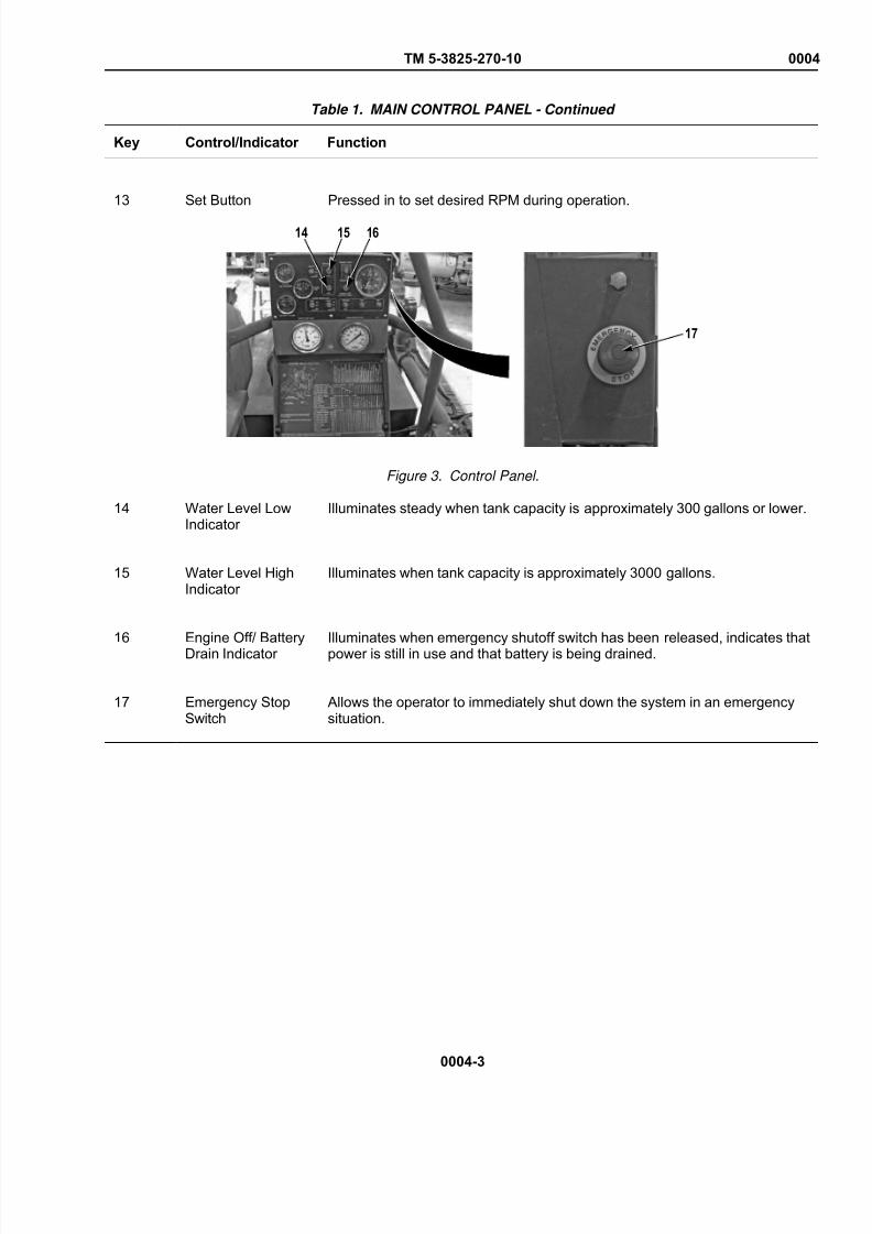
8/6/2019 TM 5-3825-270-10 ENGINEER MISSION MODULE WATER DISTRIBUTION
http://slidepdf.com/reader/full/tm-5-3825-270-10-engineer-mission-module-water-distribution 55/483
Table 1. MAIN CONTROL PANEL - Continued
Key Control/Indicator Function
13 Set Button Pressed in to set desired RPM during operation.
14 15 16
17
Figure 3. Control Panel.
14 Water Level LowIndicator
Illuminates steady when tank capacity is approximately 300 gallons or lower.
15 Water Level HighIndicator
Illuminates when tank capacity is approximately 3000 gallons.
16 Engine Off/ BatteryDrain Indicator
Illuminates when emergency shutoff switch has been released, indicates thatpower is still in use and that battery is being drained.
17 Emergency StopSwitch
Allows the operator to immediately shut down the system in an emergencysituation.
TM 5-3825-270-10 0004
0004-3
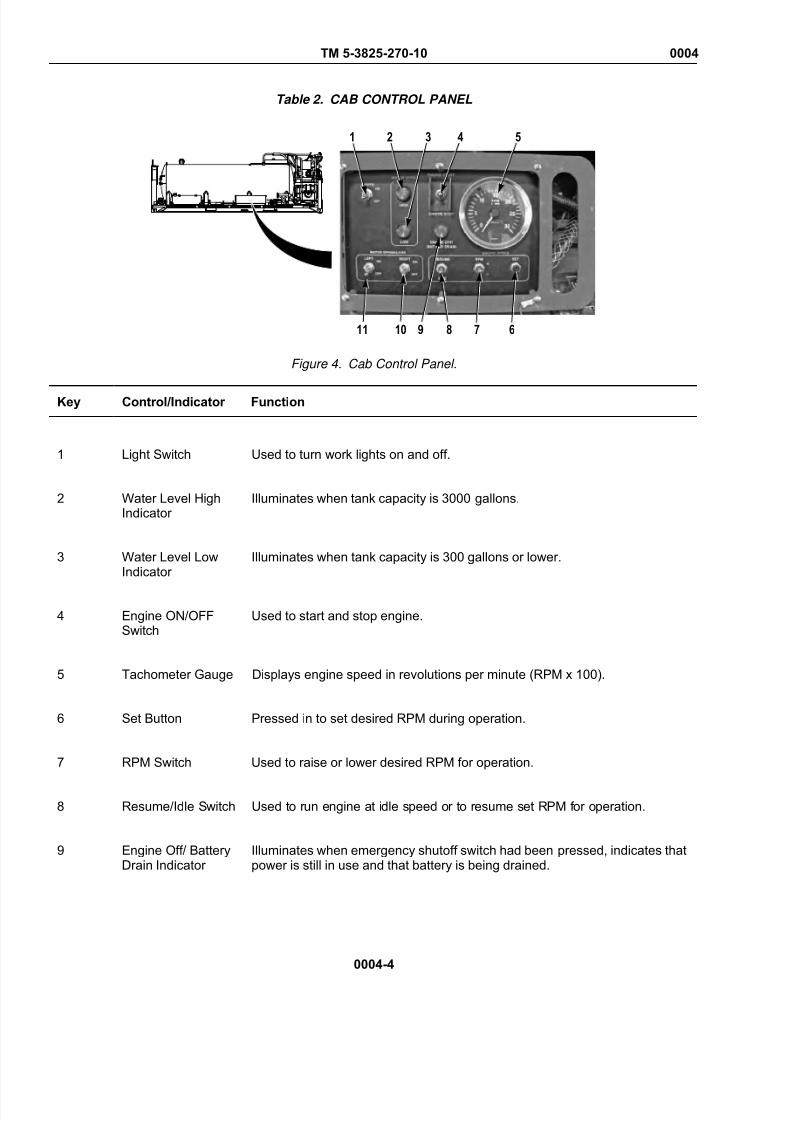
8/6/2019 TM 5-3825-270-10 ENGINEER MISSION MODULE WATER DISTRIBUTION
http://slidepdf.com/reader/full/tm-5-3825-270-10-engineer-mission-module-water-distribution 56/483
Table 2. CAB CONTROL PANEL
1
11 10 89 7 6
2 3 4 5
Figure 4. Cab Control Panel.
Key Control/Indicator Function
1 Light Switch Used to turn work lights on and off.
2 Water Level HighIndicator
Illuminates when tank capacity is 3000 gallons.
3 Water Level LowIndicator
Illuminates when tank capacity is 300 gallons or lower.
4 Engine ON/OFFSwitch
Used to start and stop engine.
5 Tachometer Gauge Displays engine speed in revolutions per minute (RPM x 100).
6 Set Button Pressed in to set desired RPM during operation.
7 RPM Switch Used to raise or lower desired RPM for operation.
8 Resume/Idle Switch Used to run engine at idle speed or to resume set RPM for operation.
9 Engine Off/ BatteryDrain Indicator
Illuminates when emergency shutoff switch had been pressed, indicates thatpower is still in use and that battery is being drained.
TM 5-3825-270-10 0004
0004-4

8/6/2019 TM 5-3825-270-10 ENGINEER MISSION MODULE WATER DISTRIBUTION
http://slidepdf.com/reader/full/tm-5-3825-270-10-engineer-mission-module-water-distribution 57/483
Table 2. CAB CONTROL PANEL - Continued
Key Control/Indicator Function
10 Right Side Water
Sprinkler Switch
Used to turn Right Sprinklers on and off.
11 Left Side Water Sprinkler Switch
Used to turn Left Sprinklers on and off.
Table 3. VALVES
1 2 3
Figure 5. Valves.
Key Control/Indicator Function
1 Valve 6 (V6) Allows water to be routed to water turret when opened.
2 Valve 7 (V7) Allows water to be routed to hose reel when opened.
3 Valve 5 (V5) Allows water to enter water pump for operations when opened.
TM 5-3825-270-10 0004
0004-5

8/6/2019 TM 5-3825-270-10 ENGINEER MISSION MODULE WATER DISTRIBUTION
http://slidepdf.com/reader/full/tm-5-3825-270-10-engineer-mission-module-water-distribution 58/483
Table 3. VALVES - Continued
Key Control/Indicator Function
4 76 85
Figure 6. Valves.
4 Valve 3 (V3) Allows tanks to be filled from road side with external 2.5 in. (63.5 mm) hosewhen opened. Can also be used during complete draining of tank.
5 Valve 1 (V1) Main valve- Used during operation of hose reel, strainer, water turret, andsprinklers, or when back flushing.
6 Valve 8 (V8) Allows water to be routed to gravity sprinkler bar when opened.
7 Valve 2 (V2) Allows tanks to be filled from curb side with external 5 in. (127 mm) hose. Canalso be used during complete draining of tank.
8 Valve 4 (V4) Allows tank to be filled from curb side with external 2.5 in. (63.5 mm) hose whenopened. Can also be used during complete draining of tank.
END OF WORK PACKAGE
TM 5-3825-270-10 0004
0004-6
8/6/2019 TM 5-3825-270-10 ENGINEER MISSION MODULE WATER DISTRIBUTION
http://slidepdf.com/reader/full/tm-5-3825-270-10-engineer-mission-module-water-distribution 59/483
OPERATOR MAINTENANCEPREPARATION FOR OPERATION/ENGINE START-UP
INITIAL SETUP:
Not Applicable
PREPARATION FOR OPERATION/ENGINE START-UP
1. Refer to (TM 9-2320-364-10) for Operation of PLS truck.
2. Inspect water distributor for damage that may have occurred during transport.
3. Check and tighten all fasteners, body tie-down bolts, pipe and circulating line connections, etc., that may havloosened during transit.
4. Fill water distributor with at least 300 gallons of water (WP 0011).
CAUTION
Do not let engine pump run more than 5 minutes without circulating water through pump.Failure to comply may result in damage to equipment.
5. Start engine and circulate water (WP 0018).
END OF TASK
END OF WORK PACKAGE
TM 5-3825-270-10 0005
0005-1/2 blank

8/6/2019 TM 5-3825-270-10 ENGINEER MISSION MODULE WATER DISTRIBUTION
http://slidepdf.com/reader/full/tm-5-3825-270-10-engineer-mission-module-water-distribution 60/483

8/6/2019 TM 5-3825-270-10 ENGINEER MISSION MODULE WATER DISTRIBUTION
http://slidepdf.com/reader/full/tm-5-3825-270-10-engineer-mission-module-water-distribution 61/483
OPERATOR MAINTENANCEOPERATING LIGHTS
INITIAL SETUP:
Not Applicable
OPERATING LIGHTS
NOTE
• Emergency stop switch must be ON to supply power to the electrical system.
• The light switch has three positions: ON is the up position, middle is the OFF position,and down is the CAB CONTROL position.
1. Disconnect t-handle (Figure 1, Item 1) from control panel cover (Figure 1, Item 2).
1 2
Figure 1. Operating Lights.
2. Open control panel cover (Figure 1, Item 2).
3. Place light switch (Figure 2, Item 3) to ON position to turn work lights (Figure 2, Item 4) on and back to OFFto turn work lights off.
TM 5-3825-270-10 0006
0006-1

8/6/2019 TM 5-3825-270-10 ENGINEER MISSION MODULE WATER DISTRIBUTION
http://slidepdf.com/reader/full/tm-5-3825-270-10-engineer-mission-module-water-distribution 62/483
OPERATING LIGHTS - Continued
34
Figure 2. Operating Lights.
4. Place light switch (Figure 3, Item 3) to CAB CONTROL to operate work lights (Figure 3, Item 4) from cab control
box (Figure 3, Item 5).
5
43
Figure 3. Operating Lights.
5. Connect universal power interface kit (UPIK) (WP 0012).
NOTE
Ensure emergency stop switch is in the OFF position when mission is complete.
6. Place light switch (Figure 4, Item 3) on cab control box (Figure 4, Item 5) to ON position to turn work lights(Figure 4, Item 4) on, and back to OFF to turn work lights off.
TM 5-3825-270-10 0006
0006-2

8/6/2019 TM 5-3825-270-10 ENGINEER MISSION MODULE WATER DISTRIBUTION
http://slidepdf.com/reader/full/tm-5-3825-270-10-engineer-mission-module-water-distribution 63/483
OPERATING LIGHTS - Continued
5
43
Figure 4. Operating Lights.
END OF TASK
END OF WORK PACKAGE
TM 5-3825-270-10 0006
0006-3/4 blank

8/6/2019 TM 5-3825-270-10 ENGINEER MISSION MODULE WATER DISTRIBUTION
http://slidepdf.com/reader/full/tm-5-3825-270-10-engineer-mission-module-water-distribution 64/483

8/6/2019 TM 5-3825-270-10 ENGINEER MISSION MODULE WATER DISTRIBUTION
http://slidepdf.com/reader/full/tm-5-3825-270-10-engineer-mission-module-water-distribution 65/483
OPERATOR MAINTENANCELOADING/UNLOADING WATER DISTRIBUTOR ON PLS OR TRAILER
INITIAL SETUP:
Equipment ConditionDisconnect UPIK (Unloading only). (WP 0012)
LOADING/UNLOADING WATER DISTRIBUTOR ON PLS OR TRAILER
The Water Distributor is capable of being loaded, or unloaded on any PLS truck, or PLS trailer (PLST). (TM9-2320-364-10)
END OF TASK
END OF WORK PACKAGE
TM 5-3825-270-10 0007
0007-1/2 blank

8/6/2019 TM 5-3825-270-10 ENGINEER MISSION MODULE WATER DISTRIBUTION
http://slidepdf.com/reader/full/tm-5-3825-270-10-engineer-mission-module-water-distribution 66/483
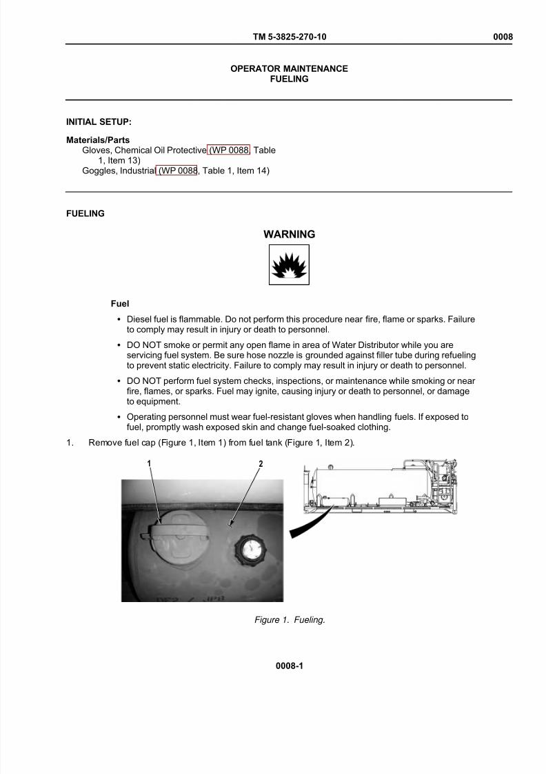
8/6/2019 TM 5-3825-270-10 ENGINEER MISSION MODULE WATER DISTRIBUTION
http://slidepdf.com/reader/full/tm-5-3825-270-10-engineer-mission-module-water-distribution 67/483
OPERATOR MAINTENANCEFUELING
INITIAL SETUP:
Materials/PartsGloves, Chemical Oil Protective (WP 0088, Table
1, Item 13)Goggles, Industrial (WP 0088, Table 1, Item 14)
FUELING
WARNING
Fuel
• Diesel fuel is flammable. Do not perform this procedure near fire, flame or sparks. Failureto comply may result in injury or death to personnel.
• DO NOT smoke or permit any open flame in area of Water Distributor while you areservicing fuel system. Be sure hose nozzle is grounded against filler tube during refuelingto prevent static electricity. Failure to comply may result in injury or death to personnel.
• DO NOT perform fuel system checks, inspections, or maintenance while smoking or near fire, flames, or sparks. Fuel may ignite, causing injury or death to personnel, or damageto equipment.
• Operating personnel must wear fuel-resistant gloves when handling fuels. If exposed tofuel, promptly wash exposed skin and change fuel-soaked clothing.
1. Remove fuel cap (Figure 1, Item 1) from fuel tank (Figure 1, Item 2).
21
Figure 1. Fueling.
TM 5-3825-270-10 0008
0008-1

8/6/2019 TM 5-3825-270-10 ENGINEER MISSION MODULE WATER DISTRIBUTION
http://slidepdf.com/reader/full/tm-5-3825-270-10-engineer-mission-module-water-distribution 68/483
FUELING - Continued
2. Fill fuel tank (Figure 1, Item 2). When fuel tank has been filled, replace fuel cap (Figure 1, Item 1) on fuel tank.
END OF TASK
END OF WORK PACKAGE
TM 5-3825-270-10 0008
0008-2

8/6/2019 TM 5-3825-270-10 ENGINEER MISSION MODULE WATER DISTRIBUTION
http://slidepdf.com/reader/full/tm-5-3825-270-10-engineer-mission-module-water-distribution 69/483
OPERATOR MAINTENANCEFIRE EXTINGUISHER OPERATION
INITIAL SETUP:
Not Applicable
FIRE EXTINGUISHER OPERATION
WARNING
• Fire extinguisher contents are under pressure. Do not puncture or incinerate.
• DO NOT store at high temperatures above 120°F (49°C).
• Avoid inhaling the extinguishing agent. Avoid inhaling smoke and fumes - all fires releasetoxic substances that are harmful. DO NOT remain in a closed area after use. Evacuatethe area immediately and ventilate thoroughly before re-entering.
• Although extinguishing agents are non-toxic when properly used, contact with them maycause irritation to eyes, nose, and throat and other allergic symptoms.
• Failure to comply with the above warnings could result in injury or death to personnel or damage to equipment.
NOTE
This fire extinguisher can be used on trash, wood, paper, flammable liquids, and electricalequipment.
1. Release clamp (Figure 1, Item 6).
5
4
32
1
67
Figure 1. Fire Extinguisher Operation.
TM 5-3825-270-10 0009
0009-1

8/6/2019 TM 5-3825-270-10 ENGINEER MISSION MODULE WATER DISTRIBUTION
http://slidepdf.com/reader/full/tm-5-3825-270-10-engineer-mission-module-water-distribution 70/483
FIRE EXTINGUISHER OPERATION - Continued
2. Remove fire extinguisher (Figure 1, Item 5) from mounting bracket (Figure 1, Item 1).
3. Hold fire extinguisher (Figure 1, Item 5) upright, and pull safety pin (Figure 1, Item 4) to break plastic tie (Figure1, Item 3).
4. Point nozzle (Figure 1, Item 7) at base of fire.5. Squeeze lever (Figure 1, Item 2) and sweep side to side.
6. Place fire extinguisher (Figure 1, Item 5) on bracket (Figure 1, Item 1).
7. Secure latch (Figure 1, Item 6).
END OF TASK
END OF WORK PACKAGE
TM 5-3825-270-10 0009
0009-2
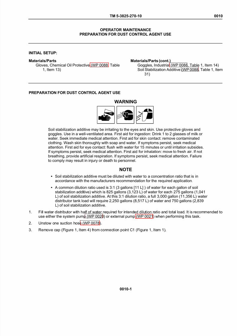
8/6/2019 TM 5-3825-270-10 ENGINEER MISSION MODULE WATER DISTRIBUTION
http://slidepdf.com/reader/full/tm-5-3825-270-10-engineer-mission-module-water-distribution 71/483
OPERATOR MAINTENANCEPREPARATION FOR DUST CONTROL AGENT USE
INITIAL SETUP:
Materials/PartsGloves, Chemical Oil Protective (WP 0088, Table
1, Item 13)
Materials/Parts (cont.)Goggles, Industrial (WP 0088, Table 1, Item 14)Soil Stabilization Additive (WP 0088, Table 1, Item
31)
PREPARATION FOR DUST CONTROL AGENT USE
WARNING
Soil stabilization additive may be irritating to the eyes and skin. Use protective gloves andgoggles. Use in a well-ventilated area. First aid for ingestion: Drink 1 to 2 glasses of milk or water. Seek immediate medical attention. First aid for skin contact: remove contaminatedclothing. Wash skin thoroughly with soap and water. If symptoms persist, seek medicalattention. First aid for eye contact: flush with water for 15 minutes or until irritation subsides.If symptoms persist, seek medical attention. First aid for inhalation: move to fresh air. If notbreathing, provide artificial respiration. If symptoms persist, seek medical attention. Failureto comply may result in injury or death to personnel.
NOTE
• Soil stabilization additive must be diluted with water to a concentration ratio that is inaccordance with the manufacturers recommendation for the required application.
• A common dilution ratio used is 3:1 (3 gallons [11 L] ) of water for each gallon of soilstabilization additive) which is 825 gallons (3,123 L) of water for each 275 gallons (1,041L) of soil stabilization additive. At this 3:1 dilution ratio, a full 3,000 gallon (11,356 L) water distributor tank load will require 2,250 gallons (8,517 L) of water and 750 gallons (2,839L) of soil stabilization additive.
1. Fill water distributor with half of water required for intended dilution ratio and total load. It is recommended touse either the system pump (WP 0020) or external pump (WP 0021) when performing this task.
2. Unstow one suction hose (WP 0078).
3. Remove cap (Figure 1, Item 4) from connection point C1 (Figure 1, Item 1).
TM 5-3825-270-10 0010
0010-1

8/6/2019 TM 5-3825-270-10 ENGINEER MISSION MODULE WATER DISTRIBUTION
http://slidepdf.com/reader/full/tm-5-3825-270-10-engineer-mission-module-water-distribution 72/483
PREPARATION FOR DUST CONTROL AGENT USE - Continued
1
2
4 3
Figure 1. Preparation For Dust Control Agent Use.
4. Remove cap (Figure 1, Item 3) and attach suction hose (Figure 1, Item 2) to connection point C1 (Figure 1,
Item 1).
NOTE
Couplings are provided in the stowage box for multiple configurations of soil stabilizationadditive totes.
5. Unstow 2" coupling cam (Figure 2, Item 8), 3" coupling cam (Figure 2, Item 6) and reducer (Figure 2, Item 7)from stowage box (Figure 2, Item 5).
TM 5-3825-270-10 0010
0010-2
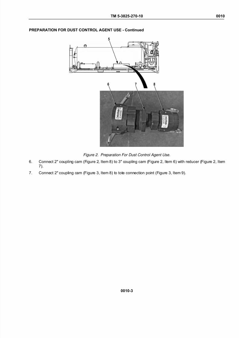
8/6/2019 TM 5-3825-270-10 ENGINEER MISSION MODULE WATER DISTRIBUTION
http://slidepdf.com/reader/full/tm-5-3825-270-10-engineer-mission-module-water-distribution 73/483
PREPARATION FOR DUST CONTROL AGENT USE - Continued
5
6 7 8
Figure 2. Preparation For Dust Control Agent Use.
6. Connect 2" coupling cam (Figure 2, Item 8) to 3" coupling cam (Figure 2, Item 6) with reducer (Figure 2, Item7).
7. Connect 2" coupling cam (Figure 3, Item 8) to tote connection point (Figure 3, Item 9).
TM 5-3825-270-10 0010
0010-3

8/6/2019 TM 5-3825-270-10 ENGINEER MISSION MODULE WATER DISTRIBUTION
http://slidepdf.com/reader/full/tm-5-3825-270-10-engineer-mission-module-water-distribution 74/483
PREPARATION FOR DUST CONTROL AGENT USE - Continued
8, 9
6
2
11
1210
10
Figure 3. Preparation For Dust Control Agent Use.
8. Remove cap (Figure 3, Item 11) from suction hose (Figure 3, Item 2).
9. Attach suction hose (Figure 3, Item 2) to 3" coupling cam (Figure 3, Item 6).
10. Remove cap (Figure 3, Item 12) from tote (Figure 3, Item 10).
11. Open valve V1 (Figure 4, Item 13).
TM 5-3825-270-10 0010
0010-4

8/6/2019 TM 5-3825-270-10 ENGINEER MISSION MODULE WATER DISTRIBUTION
http://slidepdf.com/reader/full/tm-5-3825-270-10-engineer-mission-module-water-distribution 75/483
PREPARATION FOR DUST CONTROL AGENT USE - Continued
13
Figure 4. Preparation For Dust Control Agent Use.
12. Open valve V5 (Figure 5, Item 14).
TM 5-3825-270-10 0010
0010-5

8/6/2019 TM 5-3825-270-10 ENGINEER MISSION MODULE WATER DISTRIBUTION
http://slidepdf.com/reader/full/tm-5-3825-270-10-engineer-mission-module-water-distribution 76/483
PREPARATION FOR DUST CONTROL AGENT USE - Continued
14
Figure 5. Preparation For Dust Control Agent Use.
13. Open control panel cover (Figure 6, Item 15) by releasing rubber t-handle (Figure 6, Item 16).
1615
Figure 6. Preparation For Dust Control Agent Use.
14. Pull out emergency stop button (Figure 7, Item 19).
TM 5-3825-270-10 0010
0010-6

8/6/2019 TM 5-3825-270-10 ENGINEER MISSION MODULE WATER DISTRIBUTION
http://slidepdf.com/reader/full/tm-5-3825-270-10-engineer-mission-module-water-distribution 77/483
PREPARATION FOR DUST CONTROL AGENT USE - Continued
19
21 20
1817
Figure 7. Preparation For Dust Control Agent Use.
CAUTION
Release engine start/stop switch once engine is started. Failure to comply may result indamage to equipment.
15. Start engine by pressing up and holding the engine start/stop switch (Figure 7, Item 17) until engine is starte
16. Adjust engine rpm (Figure 7, Item 18) to 1500 rpm by pressing up or down on the rpm switch (Figure 7, Item21).
CAUTION
• Ensure that engine speed is set to 1500 rpm. Failure to comply may result in damage toequipment.
• DO NOT allow engine to run longer than necessary to empty soil stabilization additiveinto water tank. Soil stabilization additive will foam and cause expansion of product.Failure to comply may result in damage to equipment.
17. When engine rpm (Figure 7, Item 18) is to desired setting press set switch (Figure 7, Item 20) to set rpm .
18. Slowly close valve V1 (Figure 8, Item 13).
TM 5-3825-270-10 0010
0010-7

8/6/2019 TM 5-3825-270-10 ENGINEER MISSION MODULE WATER DISTRIBUTION
http://slidepdf.com/reader/full/tm-5-3825-270-10-engineer-mission-module-water-distribution 78/483
PREPARATION FOR DUST CONTROL AGENT USE - Continued
13
Figure 8. Preparation For Dust Control Agent Use.
19. Open valve (Figure 9, Item 22) on tote (Figure 9, Item 10).
2210
Figure 9. Preparation For Dust Control Agent Use.
CAUTION
Engine speed must be at idle speed before engine is shut down. Failure to comply may resultin damage to equipment.
20. When loading procedure is complete, press RESUME/IDLE switch (Figure 10, Item 23) to the IDLE positionto return engine rpm (Figure 10, Item 18) to idle speed.
TM 5-3825-270-10 0010
0010-8
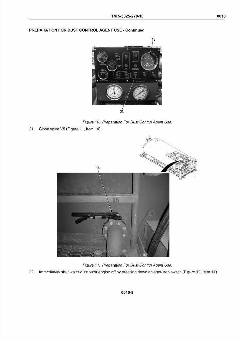
8/6/2019 TM 5-3825-270-10 ENGINEER MISSION MODULE WATER DISTRIBUTION
http://slidepdf.com/reader/full/tm-5-3825-270-10-engineer-mission-module-water-distribution 79/483
PREPARATION FOR DUST CONTROL AGENT USE - Continued
23
18
Figure 10. Preparation For Dust Control Agent Use.
21. Close valve V5 (Figure 11, Item 14).
14
Figure 11. Preparation For Dust Control Agent Use.
22. Immediately shut water distributor engine off by pressing down on start/stop switch (Figure 12, Item 17).
TM 5-3825-270-10 0010
0010-9

8/6/2019 TM 5-3825-270-10 ENGINEER MISSION MODULE WATER DISTRIBUTION
http://slidepdf.com/reader/full/tm-5-3825-270-10-engineer-mission-module-water-distribution 80/483
PREPARATION FOR DUST CONTROL AGENT USE - Continued
17
Figure 12. Preparation For Dust Control Agent Use.
23. Close valve (Figure 13, Item 22) on tote (Figure 13, Item 10).
8, 9
6
2
10
22
Figure 13. Preparation For Dust Control Agent Use.
24. Disconnect 2" coupling cam (Figure 13, Item 8) from tote connection point (Figure 13, Item 9).
25. Repeat Steps (7) through (24) for any additional totes (Figure 13, Item 10) of soil stabilization additive requiredfor intended load.
26. Disconnect suction hose (Figure 13, Item 2) from 3" coupling cam (Figure 13, Item 6) on tote (Figure 13, Item10).
27. Fill water distributor with remaining half of water required for intended dilution ratio and total load. It isrecommended to use either the system pump (WP 0020) or external pump (WP 0021) when performing thistask.
28. Disconnect suction hose (Figure 14, Item 2) from connection point C1 (Figure 14, Item 1).
TM 5-3825-270-10 0010
0010-10
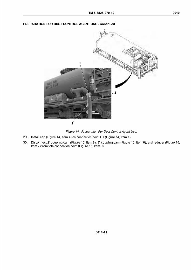
8/6/2019 TM 5-3825-270-10 ENGINEER MISSION MODULE WATER DISTRIBUTION
http://slidepdf.com/reader/full/tm-5-3825-270-10-engineer-mission-module-water-distribution 81/483
PREPARATION FOR DUST CONTROL AGENT USE - Continued
1
2
4
Figure 14. Preparation For Dust Control Agent Use.
29. Install cap (Figure 14, Item 4) on connection point C1 (Figure 14, Item 1).
30. Disconnect 2" coupling cam (Figure 15, Item 8), 3" coupling cam (Figure 15, Item 6), and reducer (Figure 15Item 7) from tote connection point (Figure 15, Item 9).
TM 5-3825-270-10 0010
0010-11

8/6/2019 TM 5-3825-270-10 ENGINEER MISSION MODULE WATER DISTRIBUTION
http://slidepdf.com/reader/full/tm-5-3825-270-10-engineer-mission-module-water-distribution 82/483
PREPARATION FOR DUST CONTROL AGENT USE - Continued
6, 7 8, 9
Figure 15. Preparation For Dust Control Agent Use.
CAUTION
Ensure hose and coupling adapters are cleaned of soil stabilization additive immediately after use. Failure to comply may result in damage to equipment.
31. Install two caps (Figure 16, Items 11 and 3) on suction hose (Figure 16, Item 2).
22
11 3
Figure 16. Preparation For Dust Control Agent Use.
32. Stow hose (WP 0078).
33. Stow 2" coupling cam (Figure 17, Item 8), 3" coupling cam (Figure 17, Item 6), and reducer (Figure 17, Item7) in stowage box (Figure 17, Item 5).
TM 5-3825-270-10 0010
0010-12

8/6/2019 TM 5-3825-270-10 ENGINEER MISSION MODULE WATER DISTRIBUTION
http://slidepdf.com/reader/full/tm-5-3825-270-10-engineer-mission-module-water-distribution 83/483
PREPARATION FOR DUST CONTROL AGENT USE - Continued
5
6 7 8
Figure 17. Preparation For Dust Control Agent Use.
CAUTION
Use caution during spraying applications. Dust control agents when sprayed or splashed onvehicles, or other personal property is difficult to remove if allowed to dry. Wash contaminatedproperty immediately before material dries.
34. Perform mission as required.
35. When mission is completed, clean water distributor (WP 0083).
END OF TASK
END OF WORK PACKAGE
TM 5-3825-270-10 0010
0010-13/14 blank

8/6/2019 TM 5-3825-270-10 ENGINEER MISSION MODULE WATER DISTRIBUTION
http://slidepdf.com/reader/full/tm-5-3825-270-10-engineer-mission-module-water-distribution 84/483

8/6/2019 TM 5-3825-270-10 ENGINEER MISSION MODULE WATER DISTRIBUTION
http://slidepdf.com/reader/full/tm-5-3825-270-10-engineer-mission-module-water-distribution 85/483
OPERATOR MAINTENANCEFILL WATER DISTRIBUTOR FROM OVERHEAD SOURCE
INITIAL SETUP:
Not Applicable
FILL WATER DISTRIBUTOR FROM OVERHEAD SOURCE
NOTE
• If overhead water source is not available, load tank at strainer with system pump and 3"hose (WP 0020), load tank at strainer with external pump (WP 0021), or load tank at withexternal 2.5" and 5" hoses (WP 0022).
• Ensure that all valves are in closed position.
1. Position vehicle as close to water source as possible.
2. Unstow folding handrail (WP 0077).
WARNING
Manhole cover does not lock open. Injury may occur if manhole cover accidentally closes onpersonnel.
3. Open manhole cover (Figure 1, Item 1) by turning t-handle latch (Figure 1, Item 2) counter clockwise.
21
Figure 1. Fill Water Distributor From Overhead Source.
4. Insert water delivery source into manhole (Figure 2, Item 3).
TM 5-3825-270-10 0011
0011-1

8/6/2019 TM 5-3825-270-10 ENGINEER MISSION MODULE WATER DISTRIBUTION
http://slidepdf.com/reader/full/tm-5-3825-270-10-engineer-mission-module-water-distribution 86/483
FILL WATER DISTRIBUTOR FROM OVERHEAD SOURCE - Continued
43
Figure 2. Fill Water Distributor From Overhead Source.
5. Fill water distributor (Figure 2, Item 4).
6. When water distributor (Figure 2, Item 4) is filled remove water delivery source.
7. Close manhole cover (Figure 3, Item 1) and secure by turning T-handle latch (Figure 3, Item 2) clockwise untiltight.
21
Figure 3. Fill Water Distributor From Overhead Source.
8. Stow folding handrail (WP 0077).
END OF TASK
END OF WORK PACKAGE
TM 5-3825-270-10 0011
0011-2
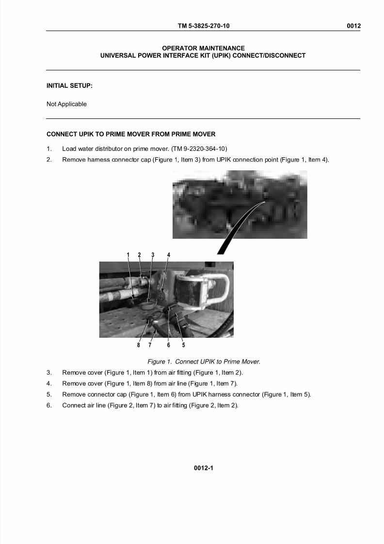
8/6/2019 TM 5-3825-270-10 ENGINEER MISSION MODULE WATER DISTRIBUTION
http://slidepdf.com/reader/full/tm-5-3825-270-10-engineer-mission-module-water-distribution 87/483
OPERATOR MAINTENANCEUNIVERSAL POWER INTERFACE KIT (UPIK) CONNECT/DISCONNECT
INITIAL SETUP:
Not Applicable
CONNECT UPIK TO PRIME MOVER FROM PRIME MOVER
1. Load water distributor on prime mover. (TM 9-2320-364-10)
2. Remove harness connector cap (Figure 1, Item 3) from UPIK connection point (Figure 1, Item 4).
1 2 3 4
8 7 6 5
Figure 1. Connect UPIK to Prime Mover.
3. Remove cover (Figure 1, Item 1) from air fitting (Figure 1, Item 2).
4. Remove cover (Figure 1, Item 8) from air line (Figure 1, Item 7).
5. Remove connector cap (Figure 1, Item 6) from UPIK harness connector (Figure 1, Item 5).
6. Connect air line (Figure 2, Item 7) to air fitting (Figure 2, Item 2).
TM 5-3825-270-10 0012
0012-1
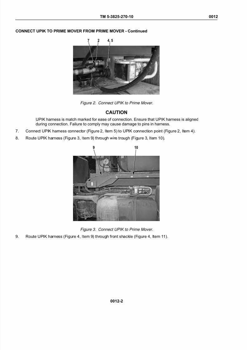
8/6/2019 TM 5-3825-270-10 ENGINEER MISSION MODULE WATER DISTRIBUTION
http://slidepdf.com/reader/full/tm-5-3825-270-10-engineer-mission-module-water-distribution 88/483
CONNECT UPIK TO PRIME MOVER FROM PRIME MOVER - Continued
4, 527
Figure 2. Connect UPIK to Prime Mover.
CAUTION
UPIK harness is match marked for ease of connection. Ensure that UPIK harness is aligned
during connection. Failure to comply may cause damage to pins in harness.
7. Connect UPIK harness connector (Figure 2, Item 5) to UPIK connection point (Figure 2, Item 4).
8. Route UPIK harness (Figure 3, Item 9) through wire trough (Figure 3, Item 10).
9 10
Figure 3. Connect UPIK to Prime Mover.
9. Route UPIK harness (Figure 4, Item 9) through front shackle (Figure 4, Item 11).
TM 5-3825-270-10 0012
0012-2

8/6/2019 TM 5-3825-270-10 ENGINEER MISSION MODULE WATER DISTRIBUTION
http://slidepdf.com/reader/full/tm-5-3825-270-10-engineer-mission-module-water-distribution 89/483
CONNECT UPIK TO PRIME MOVER FROM PRIME MOVER - Continued
9 11
Figure 4. Connect UPIK to Prime Mover.
END OF TASK
DISCONNECT UPIK FROM PRIME MOVER
1. Disconnect UPIK harness connector (Figure 5, Item 5) from UPIK connection point (Figure 5, Item 4).
4, 527
Figure 5. Disconnect UPIK from Prime Mover.
2. Disconnect air line (Figure 5, Item 7) from air fitting (Figure 5, Item 2).
3. Install connector cap (Figure 6, Item 6) on UPIK harness connector (Figure 6, Item 5).
TM 5-3825-270-10 0012
0012-3

8/6/2019 TM 5-3825-270-10 ENGINEER MISSION MODULE WATER DISTRIBUTION
http://slidepdf.com/reader/full/tm-5-3825-270-10-engineer-mission-module-water-distribution 90/483
DISCONNECT UPIK FROM PRIME MOVER - Continued
1 2 3 4
8 7 6 5
Figure 6. Disconnect UPIK from Prime Mover.
4. Install cover (Figure 6, Item 8) on air line (Figure 6, Item 7).
5. Install cover (Figure 6, Item 1) on air fitting (Figure 6, Item 2).
6. Install harness connector cap (Figure 6, Item 3) on UPIK connection point (Figure 6, Item 4).
END OF TASK
CONNECT TRAILER UPIK TO PRIME MOVER
1. Load water distributor on trailer. (TM 9-2320-364-10)
CAUTION
Red markings on UPIK harness is used as indicators for routing. Failure to properly routeUPIK harness may result in damage to harness during operation.
2. Route UPIK harness (Figure 7, Item 3) through two hooks (Figure 7, Item 1) over fuel tank (Figure 7, Item 2).
TM 5-3825-270-10 0012
0012-4

8/6/2019 TM 5-3825-270-10 ENGINEER MISSION MODULE WATER DISTRIBUTION
http://slidepdf.com/reader/full/tm-5-3825-270-10-engineer-mission-module-water-distribution 91/483
CONNECT TRAILER UPIK TO PRIME MOVER - Continued
1
2 3 1
Figure 7. Connect Trailer UPIK to Prime Mover.
3. Route UPIK harness (Figure 8, Item 3) through cable retainer (Figure 8, Item 4).
3 4
Figure 8. Connect Trailer UPIK to Prime Mover.
4. Route UPIK harness (Figure 9, Item 3) through rear shackle (Figure 9, Item 5).
TM 5-3825-270-10 0012
0012-5

8/6/2019 TM 5-3825-270-10 ENGINEER MISSION MODULE WATER DISTRIBUTION
http://slidepdf.com/reader/full/tm-5-3825-270-10-engineer-mission-module-water-distribution 92/483
CONNECT TRAILER UPIK TO PRIME MOVER - Continued
3 5
Figure 9. Connect Trailer UPIK to Prime Mover.
5. Route UPIK harness (Figure 10, Item 3) through wire trough (Figure 10, Item 6).
3 6
Figure 10. Connect Trailer UPIK to Prime Mover.
6. Route UPIK harness (Figure 11, Item 3) through front shackle (Figure 11, Item 7).
TM 5-3825-270-10 0012
0012-6

8/6/2019 TM 5-3825-270-10 ENGINEER MISSION MODULE WATER DISTRIBUTION
http://slidepdf.com/reader/full/tm-5-3825-270-10-engineer-mission-module-water-distribution 93/483
CONNECT TRAILER UPIK TO PRIME MOVER - Continued
3 7
Figure 11. Connect Trailer UPIK to Prime Mover.
7. Remove harness connector cap (Figure 12, Item 10) from UPIK connection point (Figure 12, Item 11).
8 9 10 11
15 14 13 12
Figure 12. Connect Trailer UPIK to Prime Mover.
8. Remove cover (Figure 12, Item 8) from air fitting (Figure 12, Item 9).
9. Remove cover (Figure 12, Item 15) from air line (Figure 12, Item 14).
10. Remove connector cap (Figure 12, Item 13) from UPIK harness connector (Figure 12, Item 12).
11. Connect air line (Figure 13, Item 14) to air fitting (Figure 13, Item 9).
TM 5-3825-270-10 0012
0012-7
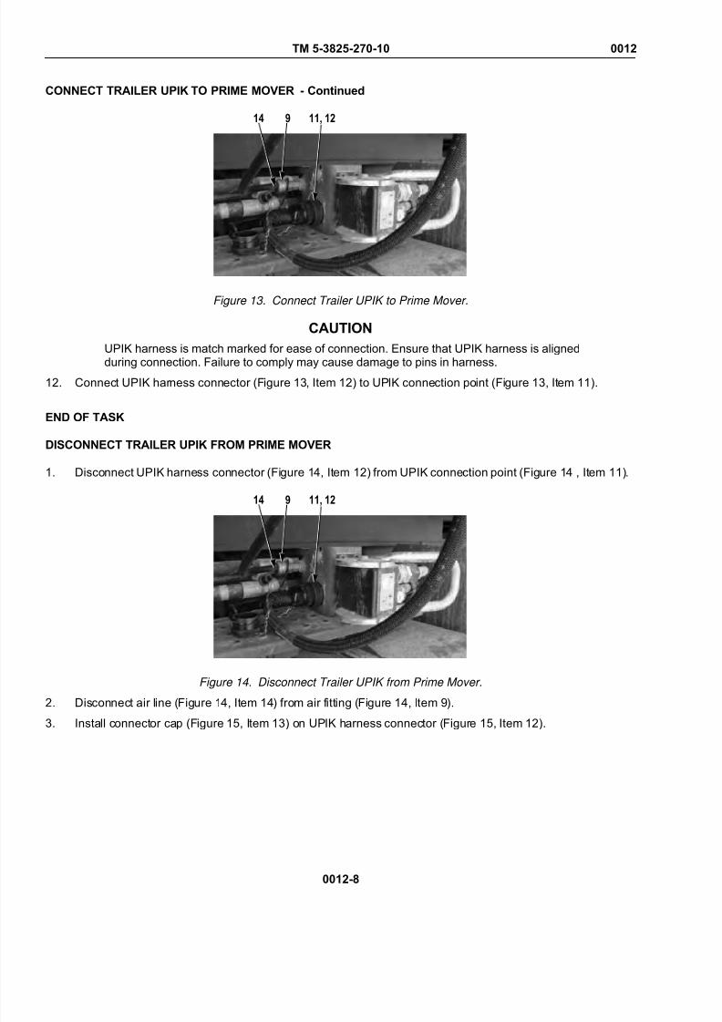
8/6/2019 TM 5-3825-270-10 ENGINEER MISSION MODULE WATER DISTRIBUTION
http://slidepdf.com/reader/full/tm-5-3825-270-10-engineer-mission-module-water-distribution 94/483
CONNECT TRAILER UPIK TO PRIME MOVER - Continued
11, 12914
Figure 13. Connect Trailer UPIK to Prime Mover.
CAUTION
UPIK harness is match marked for ease of connection. Ensure that UPIK harness is aligned
during connection. Failure to comply may cause damage to pins in harness.
12. Connect UPIK harness connector (Figure 13, Item 12) to UPIK connection point (Figure 13, Item 11).
END OF TASK
DISCONNECT TRAILER UPIK FROM PRIME MOVER
1. Disconnect UPIK harness connector (Figure 14, Item 12) from UPIK connection point (Figure 14 , Item 11).
11, 12914
Figure 14. Disconnect Trailer UPIK from Prime Mover.
2. Disconnect air line (Figure 14, Item 14) from air fitting (Figure 14, Item 9).
3. Install connector cap (Figure 15, Item 13) on UPIK harness connector (Figure 15, Item 12).
TM 5-3825-270-10 0012
0012-8
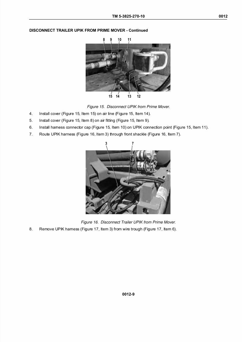
8/6/2019 TM 5-3825-270-10 ENGINEER MISSION MODULE WATER DISTRIBUTION
http://slidepdf.com/reader/full/tm-5-3825-270-10-engineer-mission-module-water-distribution 95/483
DISCONNECT TRAILER UPIK FROM PRIME MOVER - Continued
8 9 10 11
15 14 13 12
Figure 15. Disconnect UPIK from Prime Mover.
4. Install cover (Figure 15, Item 15) on air line (Figure 15, Item 14).
5. Install cover (Figure 15, Item 8) on air fitting (Figure 15, Item 9).
6. Install harness connector cap (Figure 15, Item 10) on UPIK connection point (Figure 15, Item 11).
7. Route UPIK harness (Figure 16, Item 3) through front shackle (Figure 16, Item 7).
3 7
Figure 16. Disconnect Trailer UPIK from Prime Mover.
8. Remove UPIK harness (Figure 17, Item 3) from wire trough (Figure 17, Item 6).
TM 5-3825-270-10 0012
0012-9

8/6/2019 TM 5-3825-270-10 ENGINEER MISSION MODULE WATER DISTRIBUTION
http://slidepdf.com/reader/full/tm-5-3825-270-10-engineer-mission-module-water-distribution 96/483
DISCONNECT TRAILER UPIK FROM PRIME MOVER - Continued
3 6
Figure 17. Disconnect Trailer UPIK from Prime Mover.
9. Route UPIK harness (Figure 18, Item 3) through rear shackle (Figure 18, Item 5).
3 5
Figure 18. Disconnect Trailer UPIK from Prime Mover.
10. Remove UPIK harness (Figure 19, Item 3) from cable retainer (Figure 19, Item 4).
TM 5-3825-270-10 0012
0012-10
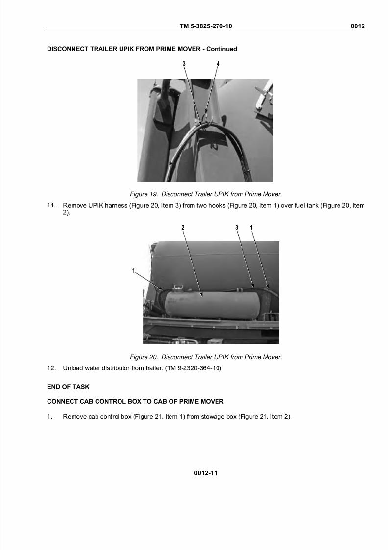
8/6/2019 TM 5-3825-270-10 ENGINEER MISSION MODULE WATER DISTRIBUTION
http://slidepdf.com/reader/full/tm-5-3825-270-10-engineer-mission-module-water-distribution 97/483
DISCONNECT TRAILER UPIK FROM PRIME MOVER - Continued
3 4
Figure 19. Disconnect Trailer UPIK from Prime Mover.
11. Remove UPIK harness (Figure 20, Item 3) from two hooks (Figure 20, Item 1) over fuel tank (Figure 20, Item2).
1
2 3 1
Figure 20. Disconnect Trailer UPIK from Prime Mover.
12. Unload water distributor from trailer. (TM 9-2320-364-10)
END OF TASK
CONNECT CAB CONTROL BOX TO CAB OF PRIME MOVER
1. Remove cab control box (Figure 21, Item 1) from stowage box (Figure 21, Item 2).
TM 5-3825-270-10 0012
0012-11

8/6/2019 TM 5-3825-270-10 ENGINEER MISSION MODULE WATER DISTRIBUTION
http://slidepdf.com/reader/full/tm-5-3825-270-10-engineer-mission-module-water-distribution 98/483
CONNECT CAB CONTROL BOX TO CAB OF PRIME MOVER - Continued
1
2
Figure 21. Connect Cab Control Box to Cab of Prime Mover.
2. Remove harness connector cap (Figure 22, Item 3) from connection point (Figure 22, Item 4).
TM 5-3825-270-10 0012
0012-12
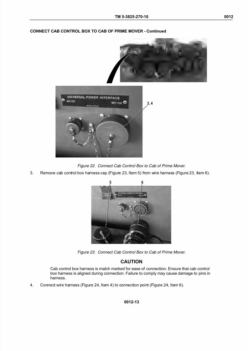
8/6/2019 TM 5-3825-270-10 ENGINEER MISSION MODULE WATER DISTRIBUTION
http://slidepdf.com/reader/full/tm-5-3825-270-10-engineer-mission-module-water-distribution 99/483
CONNECT CAB CONTROL BOX TO CAB OF PRIME MOVER - Continued
3, 4
Figure 22. Connect Cab Control Box to Cab of Prime Mover.
3. Remove cab control box harness cap (Figure 23, Item 5) from wire harness (Figure 23, Item 6).
65
Figure 23. Connect Cab Control Box to Cab of Prime Mover.
CAUTION
Cab control box harness is match marked for ease of connection. Ensure that cab controlbox harness is aligned during connection. Failure to comply may cause damage to pins inharness.
4. Connect wire harness (Figure 24, Item 4) to connection point (Figure 24, Item 6).
TM 5-3825-270-10 0012
0012-13

8/6/2019 TM 5-3825-270-10 ENGINEER MISSION MODULE WATER DISTRIBUTION
http://slidepdf.com/reader/full/tm-5-3825-270-10-engineer-mission-module-water-distribution 100/483
CONNECT CAB CONTROL BOX TO CAB OF PRIME MOVER - Continued
4, 6
Figure 24. Connect Cab Control Box to Cab of Prime Mover.
END OF TASK
DISCONNECT CAB CONTROL BOX FROM CAB OF PRIME MOVER
1. Disconnect cab control wire harness (Figure 25, Item 6) from connection point (Figure 25, Item 4).
4, 6
Figure 25. Disconnect Cab Control Box to Cab of Prime Mover.
2. Install cab control box harness cap (Figure 26, Item 5) on wire harness (Figure 26, Item 6).
TM 5-3825-270-10 0012
0012-14

8/6/2019 TM 5-3825-270-10 ENGINEER MISSION MODULE WATER DISTRIBUTION
http://slidepdf.com/reader/full/tm-5-3825-270-10-engineer-mission-module-water-distribution 101/483
DISCONNECT CAB CONTROL BOX FROM CAB OF PRIME MOVER - Continued
65
Figure 26. Disconnect Cab Control Box to Cab of Prime Mover.
3. Install harness connector cap (Figure 27, Item 3) on connection point (Figure 27, Item 4).
3, 4
Figure 27. Disconnect Cab Control Box to Cab of Prime Mover.
4. Replace cab control box (Figure 28, Item 1) in stowage box (Figure 28, Item 2).
TM 5-3825-270-10 0012
0012-15

8/6/2019 TM 5-3825-270-10 ENGINEER MISSION MODULE WATER DISTRIBUTION
http://slidepdf.com/reader/full/tm-5-3825-270-10-engineer-mission-module-water-distribution 102/483
DISCONNECT CAB CONTROL BOX FROM CAB OF PRIME MOVER - Continued
1
2
Figure 28. Disconnect Cab Control Box to Cab of Prime Mover.
END OF TASK
END OF WORK PACKAGE
TM 5-3825-270-10 0012
0012-16

8/6/2019 TM 5-3825-270-10 ENGINEER MISSION MODULE WATER DISTRIBUTION
http://slidepdf.com/reader/full/tm-5-3825-270-10-engineer-mission-module-water-distribution 103/483
OPERATOR MAINTENANCEDISCHARGE FROM GRAVITY SPRINKLER BAR
INITIAL SETUP:
Not Applicable
DISCHARGE FROM GRAVITY SPRINKLER BAR
1. Mount water distributor on PLS truck or trailer. (TM 9-2320-364-10)
2. Fill water distributor (WP 0011).
NOTE
The Gravity Sprinkler Bar is not recommended for use with soil stabilization additives.
Valve can be opened to desired position to regulate the amount of flow to be dischargedfrom gravity sprinkler bar.
3. Open valve V8 (Figure 1, Item 1) to desired position.
1
Figure 1. Discharge From Gravity Sprinkler Bar.
4. Continue with mission.
5. Once mission is complete close valve V8 (Figure 1, Item1).
END OF TASK
END OF WORK PACKAGE
TM 5-3825-270-10 0013
0013-1/2 blank
•
•

8/6/2019 TM 5-3825-270-10 ENGINEER MISSION MODULE WATER DISTRIBUTION
http://slidepdf.com/reader/full/tm-5-3825-270-10-engineer-mission-module-water-distribution 104/483

8/6/2019 TM 5-3825-270-10 ENGINEER MISSION MODULE WATER DISTRIBUTION
http://slidepdf.com/reader/full/tm-5-3825-270-10-engineer-mission-module-water-distribution 105/483
OPERATOR MAINTENANCESPRINKLER HEAD ADJUSTMENT
INITIAL SETUP:
Not Applicable
SPRINKLER HEAD ADJUSTMENT
NOTE
• Sprinkler heads are capable of being adjusted up, down, right, left, clockwise, or counterclockwise.
• Both sprinkler heads are adjusted the same way. Left side sprinkler is shown.
• Water Distributor is capable of spraying at different widths. Figures 2 through 5 showsprinkler head adjustments for approximately 2 ft, 20 ft, 40 ft and 80 ft spray widths.
1. To adjust sprinkler head (Figure 1, Item 1) up, or down, loosen two set screws (Figure 1, Item 7) and collar (Figure 1, Item 6).
12
3
4
5
67
Figure 1. Sprinkler Head Adjustment.
2. Once sprinkler head (Figure 1, Item 1) is in desired position, secure by tightening collar (Figure 1, Item 6) antwo set screws (Figure 1, Item 7).
3. To adjust sprinkler head (Figure 1, Item 1) right, or left, loosen two set screws (Figure 1, Item 4) and collar (Figure 1, Item 5).
4. Once sprinkler head (Figure 1, Item 1) is in desired position, secure by tightening collar (Figure 1, Item 5) antwo set screws (Figure 1, Item 4).
5. To adjust sprinkler head (Figure 1, Item 1) clockwise, or counterclockwise, loosen two set screws (Figure 1,Item 2) and collar (Figure 1, Item 3).
TM 5-3825-270-10 0014
0014-1

8/6/2019 TM 5-3825-270-10 ENGINEER MISSION MODULE WATER DISTRIBUTION
http://slidepdf.com/reader/full/tm-5-3825-270-10-engineer-mission-module-water-distribution 106/483
SPRINKLER HEAD ADJUSTMENT - Continued
6. Once sprinkler head (Figure 1, Item 1) is in desired position, secure by tightening collar (Figure 1, Item 3) andtwo set screws (Figure 1, Item 2).
Figure 2. 2 Ft. Width.
Figure 3. 20 Ft. Width.
TM 5-3825-270-10 0014
0014-2
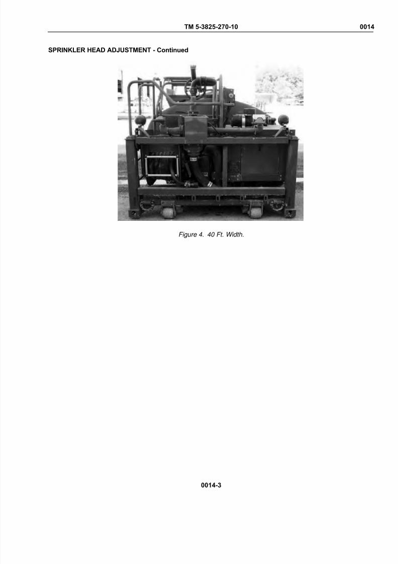
8/6/2019 TM 5-3825-270-10 ENGINEER MISSION MODULE WATER DISTRIBUTION
http://slidepdf.com/reader/full/tm-5-3825-270-10-engineer-mission-module-water-distribution 107/483
SPRINKLER HEAD ADJUSTMENT - Continued
Figure 4. 40 Ft. Width.
TM 5-3825-270-10 0014
0014-3

8/6/2019 TM 5-3825-270-10 ENGINEER MISSION MODULE WATER DISTRIBUTION
http://slidepdf.com/reader/full/tm-5-3825-270-10-engineer-mission-module-water-distribution 108/483
SPRINKLER HEAD ADJUSTMENT - Continued
Figure 5. 80 Ft. Width.
END OF TASK
END OF WORK PACKAGE
TM 5-3825-270-10 0014
0014-4

8/6/2019 TM 5-3825-270-10 ENGINEER MISSION MODULE WATER DISTRIBUTION
http://slidepdf.com/reader/full/tm-5-3825-270-10-engineer-mission-module-water-distribution 109/483
OPERATOR MAINTENANCEDISCHARGE FROM WATER TURRET ASSEMBLY
INITIAL SETUP:
Not Applicable
DISCHARGE FROM WATER TURRET ASSEMBLY
NOTE
• Ensure that all valves and petcocks are in the closed position prior to performing this task.
• For normal operating pressures, refer to WP0002, Table 1.
1. Fill water distributor (WP 0011).
2. Ensure that water pump is primed (WP 0019).
NOTE
Water distributor is equipped with two nozzles.
3. Unstow shapertip nozzle (Figure 1, Item 2) or fog nozzle (Figure 1, Item 3) from stowage box (Figure 1, Item1).
2
1
3
Figure 1. Discharge From Water Turret Assembly.
4. Remove red cap (Figure 2, Item 5) from water turret (Figure 2, Item 4).
TM 5-3825-270-10 0015
0015-1

8/6/2019 TM 5-3825-270-10 ENGINEER MISSION MODULE WATER DISTRIBUTION
http://slidepdf.com/reader/full/tm-5-3825-270-10-engineer-mission-module-water-distribution 110/483
DISCHARGE FROM WATER TURRET ASSEMBLY - Continued
4 5
Figure 2. Discharge From Water Turret Assembly.
NOTE
Both nozzles are installed the same way. Shapertip nozzle is shown.
5. Install shapertip nozzle (Figure 3, Item 2) or fog nozzle (Figure 3, Item 3) on water turret (Figure 3, Item 4).
4 2
3
Figure 3. Discharge From Water Turret Assembly.6. Open valve V1 (Figure 4, Item 6).
TM 5-3825-270-10 0015
0015-2

8/6/2019 TM 5-3825-270-10 ENGINEER MISSION MODULE WATER DISTRIBUTION
http://slidepdf.com/reader/full/tm-5-3825-270-10-engineer-mission-module-water-distribution 111/483
DISCHARGE FROM WATER TURRET ASSEMBLY - Continued
6
Figure 4. Discharge From Water Turret Assembly.
7. Open control panel cover (Figure 5, Item 7) by releasing rubber t-handle (Figure 5, Item 8).
87
Figure 5. Discharge From Water Turret Assembly.
8. Pull out emergency stop button (Figure 6, Item 10).
TM 5-3825-270-10 0015
0015-3

8/6/2019 TM 5-3825-270-10 ENGINEER MISSION MODULE WATER DISTRIBUTION
http://slidepdf.com/reader/full/tm-5-3825-270-10-engineer-mission-module-water-distribution 112/483
DISCHARGE FROM WATER TURRET ASSEMBLY - Continued
10
9
Figure 6. Discharge From Water Turret Assembly.
CAUTION
• Release engine start/stop switch once engine is started. Failure to comply may result indamage to equipment.
• Do not let engine pump run more than 5 minutes without circulating water through pump.Failure to comply may result in damage to equipment.
9. Start engine by pressing up and holding the engine start/stop switch (Figure 6, Item 9) until engine is started.
10. Unlock water turret (Figure 7, Item 4) from stowed position by turning lock knob (Figure 7, Item 11) and lockhandle (Figure 7, Item 12) counterclockwise.
TM 5-3825-270-10 0015
0015-4
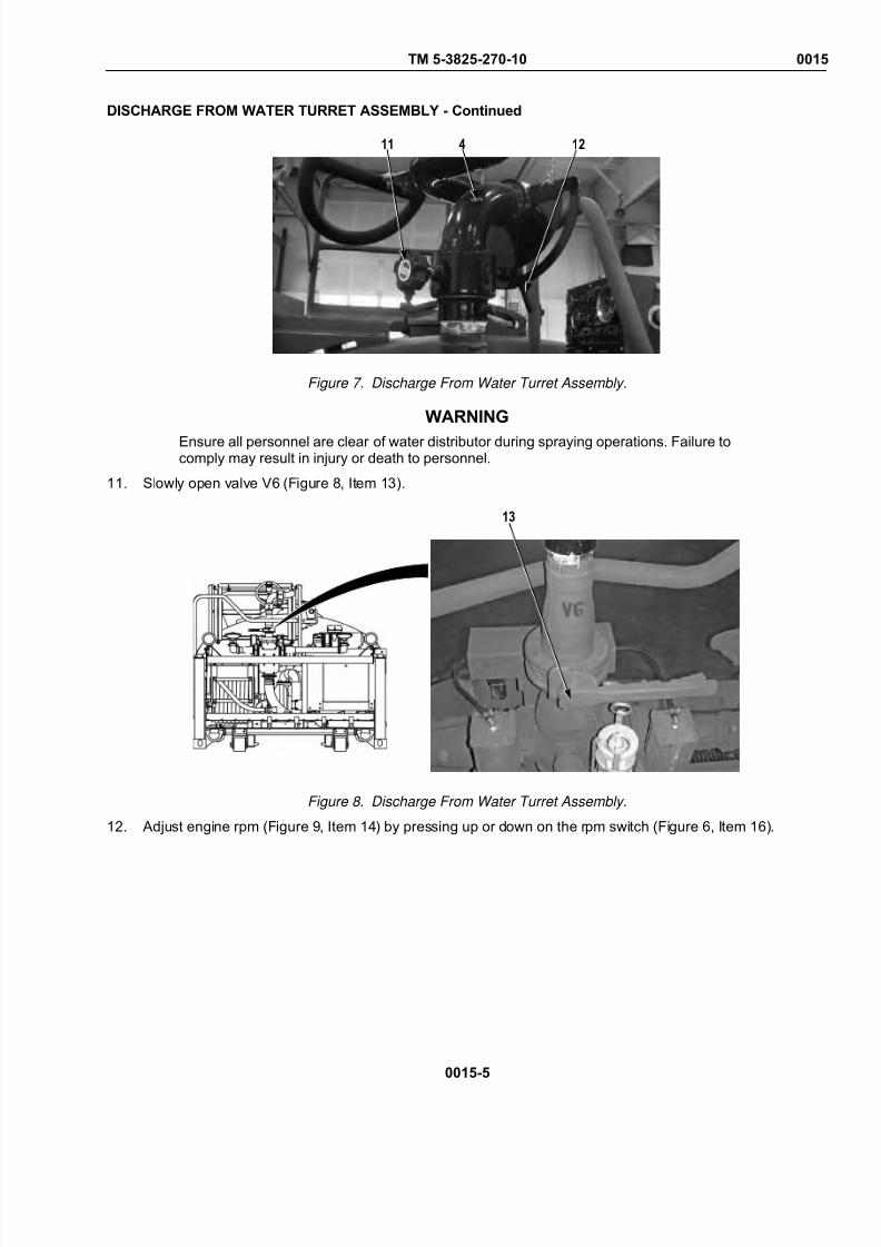
8/6/2019 TM 5-3825-270-10 ENGINEER MISSION MODULE WATER DISTRIBUTION
http://slidepdf.com/reader/full/tm-5-3825-270-10-engineer-mission-module-water-distribution 113/483
DISCHARGE FROM WATER TURRET ASSEMBLY - Continued
11 4 12
Figure 7. Discharge From Water Turret Assembly.
WARNING
Ensure all personnel are clear of water distributor during spraying operations. Failure tocomply may result in injury or death to personnel.
11. Slowly open valve V6 (Figure 8, Item 13).
13
Figure 8. Discharge From Water Turret Assembly.
12. Adjust engine rpm (Figure 9, Item 14) by pressing up or down on the rpm switch (Figure 6, Item 16).
TM 5-3825-270-10 0015
0015-5

8/6/2019 TM 5-3825-270-10 ENGINEER MISSION MODULE WATER DISTRIBUTION
http://slidepdf.com/reader/full/tm-5-3825-270-10-engineer-mission-module-water-distribution 114/483
DISCHARGE FROM WATER TURRET ASSEMBLY - Continued
14
15
16
Figure 9. Discharge From Water Turret Assembly.
CAUTION
Ensure that engine speed is more than 1500 rpm. Failure to comply may result in damage toequipment.
13. When engine rpm (Figure 9, Item 14) is to desired setting press set switch (Figure 9, Item 15) to set rpm.
14. Perform discharge procedure.
NOTEPerform Step (15) if fog nozzle is being used to adjust spray pattern.
15. Rotate fog nozzle (Figure 10, Item 3) clockwise, or counterclockwise to adjust spray pattern.
3
Figure 10. Discharge From Water Turret Assembly.
TM 5-3825-270-10 0015
0015-6

8/6/2019 TM 5-3825-270-10 ENGINEER MISSION MODULE WATER DISTRIBUTION
http://slidepdf.com/reader/full/tm-5-3825-270-10-engineer-mission-module-water-distribution 115/483
DISCHARGE FROM WATER TURRET ASSEMBLY - Continued
CAUTION
Engine speed must be at idle speed before engine is shut down. Failure to comply may resultin damage to equipment.
16. When discharge procedure is complete, press RESUME/IDLE switch (Figure 11, Item 17) to the IDLE positioto return engine rpm (Figure 11, Item 14) to idle speed.
17
14
Figure 11. Discharge From Water Turret Assembly.
17. Close valve V6 (Figure 12, Item 13).
13
Figure 12. Discharge From Water Turret Assembly.
18. Press engine START/STOP switch (Figure 13, Item 9) to stop position to shut down engine.
TM 5-3825-270-10 0015
0015-7

8/6/2019 TM 5-3825-270-10 ENGINEER MISSION MODULE WATER DISTRIBUTION
http://slidepdf.com/reader/full/tm-5-3825-270-10-engineer-mission-module-water-distribution 116/483
DISCHARGE FROM WATER TURRET ASSEMBLY - Continued
10
9
Figure 13. Discharge From Water Turret Assembly.
19. Press emergency stop button (Figure 13, Item 10) in.
20. Return water turret (Figure 14, Item 4) to stowed position and secure by turning lock handle (Figure 14, Item12) and lock knob (Figure 14, Item 11) clockwise.
11 4 12
Figure 14. Discharge From Water Turret Assembly.
21. Close control panel cover (Figure 15, Item 7) and secure using rubber t-handle (Figure 15, Item 8).
TM 5-3825-270-10 0015
0015-8
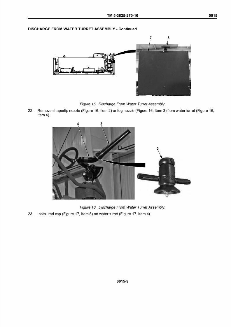
8/6/2019 TM 5-3825-270-10 ENGINEER MISSION MODULE WATER DISTRIBUTION
http://slidepdf.com/reader/full/tm-5-3825-270-10-engineer-mission-module-water-distribution 117/483
DISCHARGE FROM WATER TURRET ASSEMBLY - Continued
87
Figure 15. Discharge From Water Turret Assembly.
22. Remove shapertip nozzle (Figure 16, Item 2) or fog nozzle (Figure 16, Item 3) from water turret (Figure 16,
Item 4).
4 2
3
Figure 16. Discharge From Water Turret Assembly.
23. Install red cap (Figure 17, Item 5) on water turret (Figure 17, Item 4).
TM 5-3825-270-10 0015
0015-9

8/6/2019 TM 5-3825-270-10 ENGINEER MISSION MODULE WATER DISTRIBUTION
http://slidepdf.com/reader/full/tm-5-3825-270-10-engineer-mission-module-water-distribution 118/483
DISCHARGE FROM WATER TURRET ASSEMBLY - Continued
4 5
Figure 17. Discharge From Water Turret Assembly.24. Stow shapertip nozzle (Figure 18, Item 2) or fog nozzle (Figure 18, Item 3) in stowage box (Figure 18, Item 1).
2
1
3
Figure 18. Discharge From Water Turret Assembly.
END OF TASK
END OF WORK PACKAGE
TM 5-3825-270-10 0015
0015-10

8/6/2019 TM 5-3825-270-10 ENGINEER MISSION MODULE WATER DISTRIBUTION
http://slidepdf.com/reader/full/tm-5-3825-270-10-engineer-mission-module-water-distribution 119/483
FIELD MAINTENANCEDISCHARGE FROM SPRINKLER NOZZLES
INITIAL SETUP:
Not Applicable
DISCHARGE FROM SPRINKLER NOZZLES FROM PLATFORM
1. Mount water distributor on PLS truck or trailer. (TM 9-2320-364-10)
NOTE
• Ensure that all valves and petcocks are in the closed position prior to performing this task.
• For normal operating pressures, refer to WP0002, Table 1.
2. Fill water distributor (WP 0011).
3. Ensure that water pump is primed (WP 0019).
4. Connect universal power interface kit (UPIK) (WP 0012).
5. Open valve V1 (Figure 1, Item 1).
1
Figure 1. Discharge From Sprinkler Nozzles From Platform.
6. Open control panel cover (Figure 2, Item 2) by releasing rubber t-handle (Figure 2, Item 3).
TM 5-3825-270-10 0016
0016-1

8/6/2019 TM 5-3825-270-10 ENGINEER MISSION MODULE WATER DISTRIBUTION
http://slidepdf.com/reader/full/tm-5-3825-270-10-engineer-mission-module-water-distribution 120/483
DISCHARGE FROM SPRINKLER NOZZLES FROM PLATFORM - Continued
2 3
Figure 2. Discharge From Sprinkler Nozzles From Platform.
7. Pull out emergency stop button (Figure 3, Item 6).
6
78
54
Figure 3. Discharge From Sprinkler Nozzles From Platform.
CAUTION
• Release engine start/stop switch once engine is started. Failure to comply may result indamage to equipment.
TM 5-3825-270-10 0016
0016-2
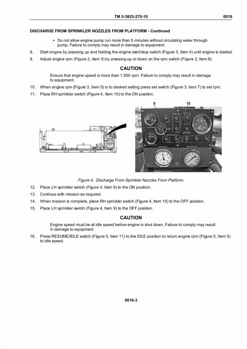
8/6/2019 TM 5-3825-270-10 ENGINEER MISSION MODULE WATER DISTRIBUTION
http://slidepdf.com/reader/full/tm-5-3825-270-10-engineer-mission-module-water-distribution 121/483
DISCHARGE FROM SPRINKLER NOZZLES FROM PLATFORM - Continued
• Do not allow engine pump run more than 5 minutes without circulating water throughpump. Failure to comply may result in damage to equipment.
8. Start engine by pressing up and holding the engine start/stop switch (Figure 3, Item 4) until engine is started
9. Adjust engine rpm (Figure 3, Item 5) by pressing up or down on the rpm switch (Figure 3, Item 8).
CAUTION
Ensure that engine speed is more than 1,500 rpm. Failure to comply may result in damageto equipment.
10. When engine rpm (Figure 3, Item 5) is to desired setting press set switch (Figure 3, Item 7) to set rpm.
11. Place RH sprinkler switch (Figure 4, Item 10) to the ON position.
9 10
Figure 4. Discharge From Sprinkler Nozzles From Platform.
12. Place LH sprinkler switch (Figure 4, Item 9) to the ON position.
13. Continue with mission as required.
14. When mission is complete, place RH sprinkler switch (Figure 4, Item 10) to the OFF position.
15. Place LH sprinkler switch (Figure 4, Item 9) to the OFF position.
CAUTION
Engine speed must be at idle speed before engine is shut down. Failure to comply may resultin damage to equipment.
16. Press RESUME/IDLE switch (Figure 5, Item 11) to the IDLE position to return engine rpm (Figure 5, Item 5)to idle speed.
TM 5-3825-270-10 0016
0016-3

8/6/2019 TM 5-3825-270-10 ENGINEER MISSION MODULE WATER DISTRIBUTION
http://slidepdf.com/reader/full/tm-5-3825-270-10-engineer-mission-module-water-distribution 122/483
DISCHARGE FROM SPRINKLER NOZZLES FROM PLATFORM - Continued
6
11
54
Figure 5. Discharge From Sprinkler Nozzles From Platform.
17. Press engine START/STOP switch (Figure 5, Item 4) to stop position to shut down engine.
18. Press emergency stop button (Figure 5, Item 6) in.
19. Close control panel cover (Figure 6, Item 2) and secure using rubber t-handle (Figure 6, Item 3).
2 3
Figure 6. Discharge From Sprinkler Nozzles From Platform.
20. Close valve V1 (Figure 7, Item 1).
TM 5-3825-270-10 0016
0016-4

8/6/2019 TM 5-3825-270-10 ENGINEER MISSION MODULE WATER DISTRIBUTION
http://slidepdf.com/reader/full/tm-5-3825-270-10-engineer-mission-module-water-distribution 123/483
DISCHARGE FROM SPRINKLER NOZZLES FROM PLATFORM - Continued
1
Figure 7. Discharge From Sprinkler Nozzles From Platform.
21. Disconnect universal power interface kit (UPIK) (WP 0012).
END OF TASK
OPERATE SPRINKLERS FROM CAB OF PRIME MOVER
CAUTION
• Disconnect UPIK harness as soon as mission is complete. Failure to comply may resultin damage to UPIK harness.
• UPIK harness is to be connected only during operation of water distributor while on trailer or vehicle. Driving over adverse conditions may result in damage to UPIK harness.
• Do not operate prime mover in reverse with UPIK harness connected to trailer. Failureto comply may result in damage to UPIK harness.
• Do not allow engine pump run more than 5 minutes without circulating water throughpump. Failure to comply may result in damage to equipment.
NOTE
• Before operating water distributor from cab of prime mover ensure that all necessaryswitches on platform control panel are set to the "CAB CONTROL" position.
• Ensure that emergency stop button is pulled out.
• Ensure that there is enough product in water distributor to complete mission.
1. Fill water distributor (WP 0011).
2. Ensure UPIK and cab control box are properly connected (WP 0012).
3. Open valve V1 (Figure 8, Item 1).
TM 5-3825-270-10 0016
0016-5

8/6/2019 TM 5-3825-270-10 ENGINEER MISSION MODULE WATER DISTRIBUTION
http://slidepdf.com/reader/full/tm-5-3825-270-10-engineer-mission-module-water-distribution 124/483
OPERATE SPRINKLERS FROM CAB OF PRIME MOVER - Continued
1
Figure 8. Discharge From Sprinkler Nozzles From Cab of Prime Mover.
4. Start engine by pressing up and holding the engine START/STOP switch (Figure 9, Item 2) until engine isstarted.
2
5 4
3
Figure 9. Discharge From Sprinkler Nozzles From Cab of Prime Mover.
5. Adjust pump engine rpm (Figure 9, Item 3) by pressing up or down on the rpm switch (Figure 9, Item 5).
6. When pump engine rpm (Figure 9, Item 3) is to desired setting press the set switch (Figure 9, Item 4) in to setrpm.
7. Refer to application charts (Figures 10, 11, and 12) for water distributor and prime mover settings as required
by mission.
TM 5-3825-270-10 0016
0016-6
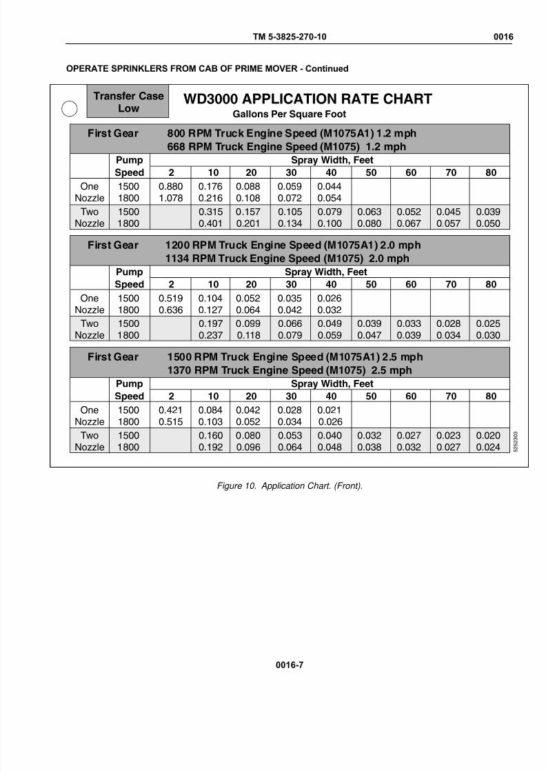
8/6/2019 TM 5-3825-270-10 ENGINEER MISSION MODULE WATER DISTRIBUTION
http://slidepdf.com/reader/full/tm-5-3825-270-10-engineer-mission-module-water-distribution 125/483
OPERATE SPRINKLERS FROM CAB OF PRIME MOVER - Continued
Transfer CaseLow
WD3000 APPLICATION RATE CHART
First Gear 800 RPM Truck Engine Speed (M1075A1) 1.2 mph668 RPM Truck Engine Speed (M1075) 1.2 mph
teeF,htdiWyarpSpmuP
Speed 2 10 20 30 40 50 60 70 80
One 1500 0.880 0.176 0.088 0.059 0.044
Nozzle 1800 1.078 0.216 0.108 0.072 0.054
Two 1500 0.315 0.157 0.105 0.079 0.063 0.052 0.045 0.039
Nozzle 1800 0.401 0.201 0.134 0.100 0.080 0.067 0.057 0.050
First Gear 1200 RPM Truck Engine Speed (M1075A1) 2.0 mph
1134 RPM Truck Engine Speed (M1075) 2.0 mph
teeF,htdiWyarpSpmuPSpeed 2 10 20 30 40 50 60 70 80
One 1500 0.519 0.104 0.052 0.035 0.026
Nozzle 1800 0.636 0.127 0.064 0.042 0.032
Two 1500 0.197 0.099 0.066 0.049 0.039 0.033 0.028 0.025
Nozzle 1800 0.237 0.118 0.079 0.059 0.047 0.039 0.034 0.030
First Gear 1500 RPM Truck Engine Speed (M1075A1) 2.5 mph
1370 RPM Truck Engine Speed (M1075) 2.5 mph
teeF,htdiWyarpSpmuP
Speed 2 10 20 30 40 50 60 70 80
One 1500 0.421 0.084 0.042 0.028 0.021
Nozzle 1800 0.515 0.103 0.052 0.034 0.026
Two 1500 0.160 0.080 0.053 0.040 0.032 0.027 0.023 0.020
Nozzle 1800 0.192 0.096 0.064 0.048 0.038 0.032 0.027 0.024
Gallons Per Square Foot
Figure 10. Application Chart. (Front).
TM 5-3825-270-10 0016
0016-7
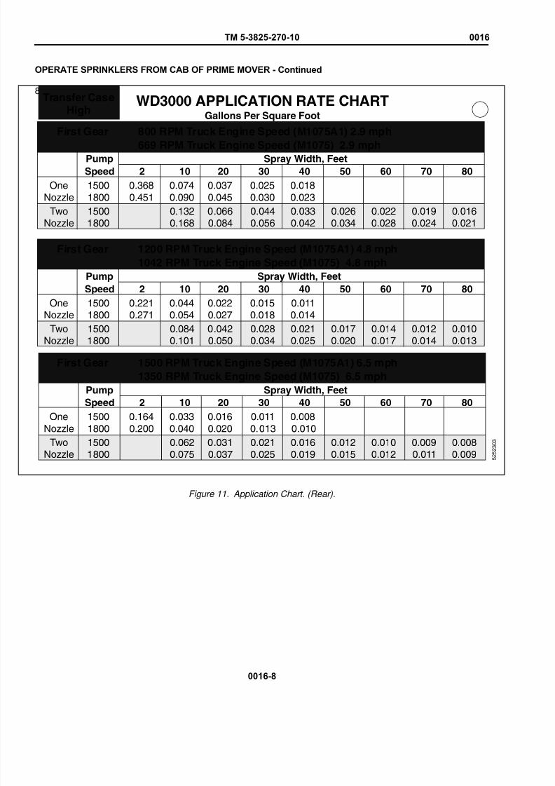
8/6/2019 TM 5-3825-270-10 ENGINEER MISSION MODULE WATER DISTRIBUTION
http://slidepdf.com/reader/full/tm-5-3825-270-10-engineer-mission-module-water-distribution 126/483
OPERATE SPRINKLERS FROM CAB OF PRIME MOVER - Continued
8.Transfer Case
High
First Gear 800 RPM Truck Engine Speed (M1075A1) 2.9 mph
669 RPM Truck Engine Speed (M1075) 2.9 mph
teeF,htdiWyarpSpmuP
Speed 2 10 20 30 40 50 60 70 80
One 1500 0.368 0.074 0.037 0.025 0.018
Nozzle 1800 0.451 0.090 0.045 0.030 0.023
Two 1500 0.132 0.066 0.044 0.033 0.026 0.022 0.019 0.016
Nozzle 1800 0.168 0.084 0.056 0.042 0.034 0.028 0.024 0.021
First Gear 1200 RPM Truck Engine Speed (M1075A1) 4.8 mph
1042 RPM Truck Engine Speed (M1075) 4.8 mph
teeF,htdiWyarpSpmuPSpeed 2 10 20 30 40 50 60 70 80
One 1500 0.221 0.044 0.022 0.015 0.011
Nozzle 1800 0.271 0.054 0.027 0.018 0.014
Two 1500 0.084 0.042 0.028 0.021 0.017 0.014 0.012 0.010
Nozzle 1800 0.101 0.050 0.034 0.025 0.020 0.017 0.014 0.013
First Gear 1500 RPM Truck Engine Speed (M1075A1) 6.5 mph
1350 RPM Truck Engine Speed (M1075) 6.5 mph
teeF,htdiWyarpSpmuP
Speed 2 10 20 30 40 50 60 70 80
One 1500 0.164 0.033 0.016 0.011 0.008
Nozzle 1800 0.200 0.040 0.020 0.013 0.010
Two 1500 0.062 0.031 0.021 0.016 0.012 0.010 0.009 0.008
Nozzle 1800 0.075 0.037 0.025 0.019 0.015 0.012 0.011 0.009
WD3000 APPLICATION RATE CHARTGallons Per Square Foot
3 0 3 2 5 2 5
Figure 11. Application Chart. (Rear).
TM 5-3825-270-10 0016
0016-8
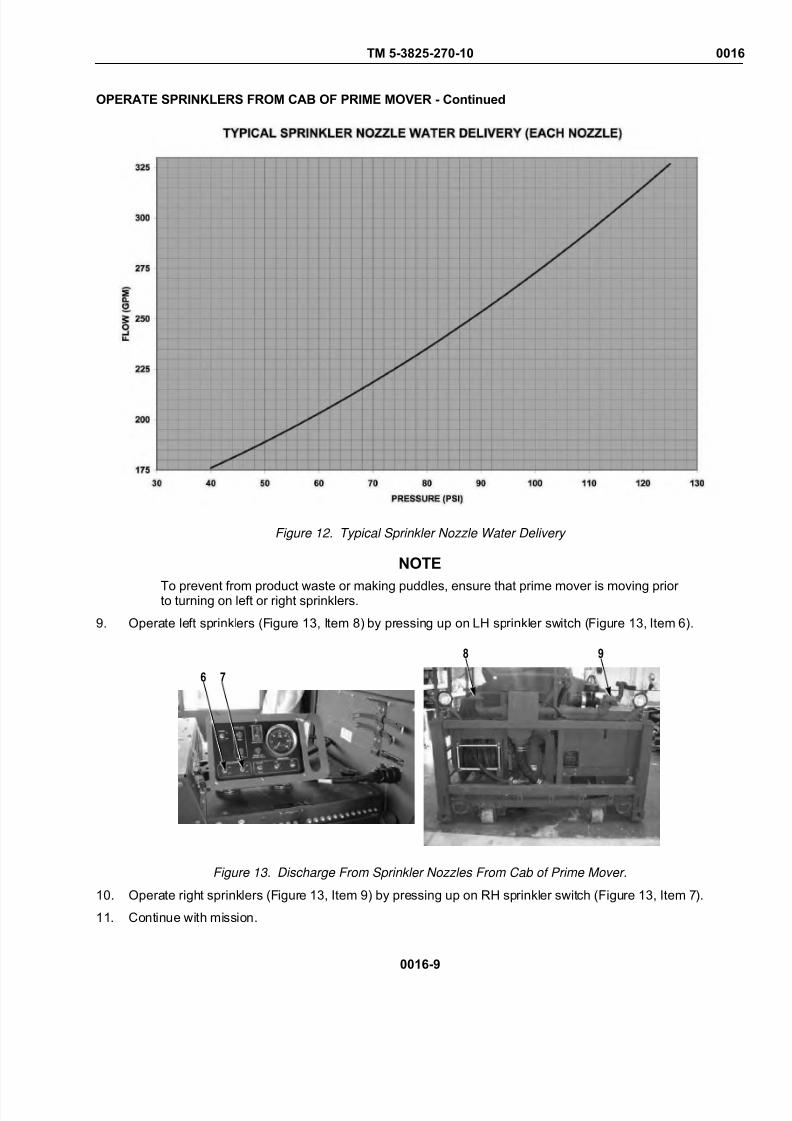
8/6/2019 TM 5-3825-270-10 ENGINEER MISSION MODULE WATER DISTRIBUTION
http://slidepdf.com/reader/full/tm-5-3825-270-10-engineer-mission-module-water-distribution 127/483
OPERATE SPRINKLERS FROM CAB OF PRIME MOVER - Continued
Figure 12. Typical Sprinkler Nozzle Water Delivery
NOTE
To prevent from product waste or making puddles, ensure that prime mover is moving prior to turning on left or right sprinklers.
9. Operate left sprinklers (Figure 13, Item 8) by pressing up on LH sprinkler switch (Figure 13, Item 6).
6 7
8 9
Figure 13. Discharge From Sprinkler Nozzles From Cab of Prime Mover.
10. Operate right sprinklers (Figure 13, Item 9) by pressing up on RH sprinkler switch (Figure 13, Item 7).
11. Continue with mission.
TM 5-3825-270-10 0016
0016-9

8/6/2019 TM 5-3825-270-10 ENGINEER MISSION MODULE WATER DISTRIBUTION
http://slidepdf.com/reader/full/tm-5-3825-270-10-engineer-mission-module-water-distribution 128/483
OPERATE SPRINKLERS FROM CAB OF PRIME MOVER - Continued
NOTE
To prevent product waste or making puddles, ensure that prime mover is moving prior toturning off left or right sprinklers.
12. When mission is complete, shut off left sprinkler (Figure 13, Item 8) by pressing LH sprinkler switch (Figure13, Item 6) to the OFF position.
13. Shut OFF right sprinkler (Figure 13, Item 9) by pressing RH sprinkler switch (Figure 13, Item 7) to the OFFposition.
CAUTION
Engine speed must be at idle speed before engine is shut down. Failure to comply may resultin damage to equipment.
14. Press RESUME/IDLE switch (Figure 14, Item 10) to the IDLE position to return pump engine rpm (Figure 14,Item 3) to idle speed.
2
10
3
Figure 14. Discharge From Sprinkler Nozzles From Cab of Prime Mover.
15. Shut water distributor engine OFF by pressing down on START/STOP switch (Figure 14, Item 2).
16. Close valve V1 (Figure 15, Item 1).
1
Figure 15. Discharge From Sprinkler Nozzles From Cab of Prime Mover.
17. Disconnect and stow cab control box (WP 0012).
TM 5-3825-270-10 0016
0016-10

8/6/2019 TM 5-3825-270-10 ENGINEER MISSION MODULE WATER DISTRIBUTION
http://slidepdf.com/reader/full/tm-5-3825-270-10-engineer-mission-module-water-distribution 129/483
OPERATE SPRINKLERS FROM CAB OF PRIME MOVER - Continued
18. Disconnect universal power interface kit (UPIK) (WP 0012).
END OF TASK
END OF WORK PACKAGE
TM 5-3825-270-10 0016
0016-11/12 blank

8/6/2019 TM 5-3825-270-10 ENGINEER MISSION MODULE WATER DISTRIBUTION
http://slidepdf.com/reader/full/tm-5-3825-270-10-engineer-mission-module-water-distribution 130/483

8/6/2019 TM 5-3825-270-10 ENGINEER MISSION MODULE WATER DISTRIBUTION
http://slidepdf.com/reader/full/tm-5-3825-270-10-engineer-mission-module-water-distribution 131/483
OPERATOR MAINTENANCEDISCHARGE FROM HOSE REEL ASSEMBLY
INITIAL SETUP:
Not Applicable
DISCHARGE FROM HOSE REEL ASSEMBLY
NOTE
• Ensure that all valves and petcocks are in the closed position prior to performing this task.
• For normal operating pressures, refer to WP0002, Table 1.
1. Fill water distributor (WP 0011).
2. Ensure that water pump is primed (WP 0019).
3. Unstow hose from hose reel (WP 0078).
4. Open valve V1 (Figure 1, Item 1).
1
Figure 1. Discharge From Hose Reel Assembly.
5. Open control panel cover (Figure 2, Item 2) by releasing rubber t-handle (Figure 2, Item 3).
TM 5-3825-270-10 0017
0017-1
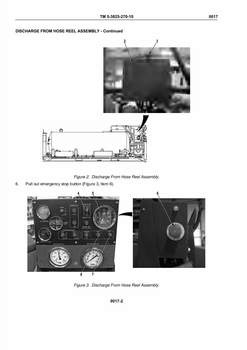
8/6/2019 TM 5-3825-270-10 ENGINEER MISSION MODULE WATER DISTRIBUTION
http://slidepdf.com/reader/full/tm-5-3825-270-10-engineer-mission-module-water-distribution 132/483
DISCHARGE FROM HOSE REEL ASSEMBLY - Continued
2 3
Figure 2. Discharge From Hose Reel Assembly.
6. Pull out emergency stop button (Figure 3, Item 6).
4
8 7
5 6
Figure 3. Discharge From Hose Reel Assembly.
TM 5-3825-270-10 0017
0017-2

8/6/2019 TM 5-3825-270-10 ENGINEER MISSION MODULE WATER DISTRIBUTION
http://slidepdf.com/reader/full/tm-5-3825-270-10-engineer-mission-module-water-distribution 133/483
DISCHARGE FROM HOSE REEL ASSEMBLY - Continued
CAUTION
• Release engine start/stop switch once engine is started. Failure to comply may result indamage to equipment.
• Do not let engine run more than 5 minutes without circulating water through pump. Failureto comply may result in damage to equipment.
7. Start engine by pressing up and holding the engine start/stop switch (Figure 3, Item 4) until engine is started
8. Adjust engine rpm (Figure 3, Item 5) by pressing up or down on the rpm switch (Figure 3, Item 8).
CAUTION
Ensure that engine speed is more than 1500 rpm. Failure to comply may result in damage toequipment.
9. When engine rpm (Figure 3, Item 5) is to desired setting press set switch (Figure 3, Item 7) to set rpm.
10. Open valve V7 (Figure 4, Item 9).
9
Figure 4. Discharge From Hose Reel Assembly.
WARNING
Use caution when opening hose nozzle to begin discharge procedure. Water is under highpressure. Failure to comply may result in injury or death to personnel.
11. Turn hose nozzle (Figure 5, Item 10) clockwise to desired spray pattern and continue mission.
TM 5-3825-270-10 0017
0017-3
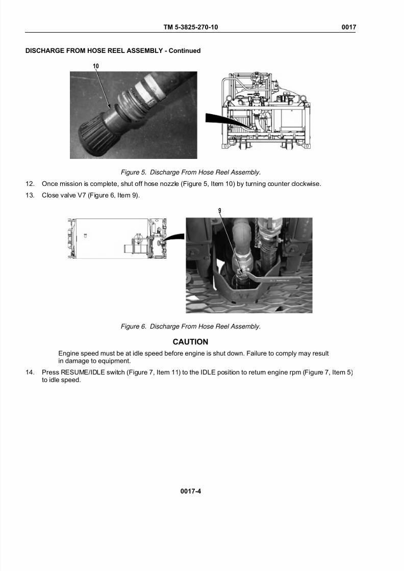
8/6/2019 TM 5-3825-270-10 ENGINEER MISSION MODULE WATER DISTRIBUTION
http://slidepdf.com/reader/full/tm-5-3825-270-10-engineer-mission-module-water-distribution 134/483
DISCHARGE FROM HOSE REEL ASSEMBLY - Continued
10
Figure 5. Discharge From Hose Reel Assembly.
12. Once mission is complete, shut off hose nozzle (Figure 5, Item 10) by turning counter clockwise.
13. Close valve V7 (Figure 6, Item 9).
9
Figure 6. Discharge From Hose Reel Assembly.
CAUTION
Engine speed must be at idle speed before engine is shut down. Failure to comply may resultin damage to equipment.
14. Press RESUME/IDLE switch (Figure 7, Item 11) to the IDLE position to return engine rpm (Figure 7, Item 5)to idle speed.
TM 5-3825-270-10 0017
0017-4
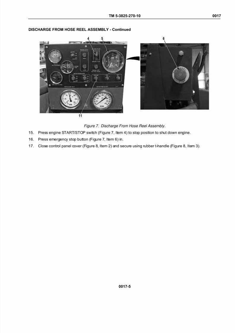
8/6/2019 TM 5-3825-270-10 ENGINEER MISSION MODULE WATER DISTRIBUTION
http://slidepdf.com/reader/full/tm-5-3825-270-10-engineer-mission-module-water-distribution 135/483
DISCHARGE FROM HOSE REEL ASSEMBLY - Continued
4
11
5 6
Figure 7. Discharge From Hose Reel Assembly.
15. Press engine START/STOP switch (Figure 7, Item 4) to stop position to shut down engine.
16. Press emergency stop button (Figure 7, Item 6) in.
17. Close control panel cover (Figure 8, Item 2) and secure using rubber t-handle (Figure 8, Item 3).
TM 5-3825-270-10 0017
0017-5

8/6/2019 TM 5-3825-270-10 ENGINEER MISSION MODULE WATER DISTRIBUTION
http://slidepdf.com/reader/full/tm-5-3825-270-10-engineer-mission-module-water-distribution 136/483
DISCHARGE FROM HOSE REEL ASSEMBLY - Continued
2 3
Figure 8. Discharge From Hose Reel Assembly.
18. Close valve V1 (Figure 9, Item 1).
1
Figure 9. Discharge From Hose Reel Assembly.
TM 5-3825-270-10 0017
0017-6

8/6/2019 TM 5-3825-270-10 ENGINEER MISSION MODULE WATER DISTRIBUTION
http://slidepdf.com/reader/full/tm-5-3825-270-10-engineer-mission-module-water-distribution 137/483
DISCHARGE FROM HOSE REEL ASSEMBLY - Continued
19. Stow hose (WP 0078).
END OF TASK
END OF WORK PACKAGE
TM 5-3825-270-10 0017
0017-7/8 blank

8/6/2019 TM 5-3825-270-10 ENGINEER MISSION MODULE WATER DISTRIBUTION
http://slidepdf.com/reader/full/tm-5-3825-270-10-engineer-mission-module-water-distribution 138/483

8/6/2019 TM 5-3825-270-10 ENGINEER MISSION MODULE WATER DISTRIBUTION
http://slidepdf.com/reader/full/tm-5-3825-270-10-engineer-mission-module-water-distribution 139/483
OPERATOR MAINTENANCECIRCULATE TANK WITH PUMP TO BLEND OR RINSE
INITIAL SETUP:
Not Applicable
CIRCULATE TANK WITH PUMP TO BLEND OR RINSE
NOTE
• Ladder may be needed to perform the following task.
• Use caution if circulating soil stabilization additive as excessive tank foaming can occur.
• Ensure that all valves and petcocks are in the closed position prior to performing this task.
1. Open valve V1 (Figure 1, Item 1).
1
Figure 1. Circulate Tank With Pump To Blend Or Rinse.
2. Open valve V5 (Figure 2, Item 2).
TM 5-3825-270-10 0018
0018-1

8/6/2019 TM 5-3825-270-10 ENGINEER MISSION MODULE WATER DISTRIBUTION
http://slidepdf.com/reader/full/tm-5-3825-270-10-engineer-mission-module-water-distribution 140/483
CIRCULATE TANK WITH PUMP TO BLEND OR RINSE - Continued
2
Figure 2. Circulate Tank With Pump To Blend Or Rinse.
3. Open control panel cover (Figure 3, Item 3) by releasing rubber t-handle (Figure 3, Item 4).
43
Figure 3. Circulate Tank With Pump To Blend Or Rinse.
4. Pull out emergency stop button (Figure 4, Item 10).
TM 5-3825-270-10 0018
0018-2

8/6/2019 TM 5-3825-270-10 ENGINEER MISSION MODULE WATER DISTRIBUTION
http://slidepdf.com/reader/full/tm-5-3825-270-10-engineer-mission-module-water-distribution 141/483
CIRCULATE TANK WITH PUMP TO BLEND OR RINSE - Continued
10
9 8 7
65
Figure 4. Circulate Tank With Pump To Blend Or Rinse.
CAUTION
• Release engine start/stop switch once engine is started. Failure to comply may result indamage to equipment.
• Do not let engine run more than 5 minutes without circulating water through pump. Failureto comply may result in damage to equipment.
5. Start engine by pressing up and holding the engine start/stop switch (Figure 4, Item 5) until engine is started
6. Adjust engine rpm (Figure 4, Item 6) by pressing up or down on the rpm switch (Figure 4, Item 8).
CAUTION
Ensure that engine speed is more than 1500 rpm. Failure to comply may result in damage toequipment.
7. When engine rpm (Figure 4, Item 6) is to desired setting press set switch (Figure 4, Item 7) to set rpm .
CAUTION
Engine speed must be at idle speed before engine is shut down. Failure to comply may resultin damage to equipment.
8. When circulation procedure is complete, press RESUME/IDLE switch (Figure 4, Item 9) to the IDLE positionto return engine rpm (Figure 4, Item 6) to idle speed.
9. Shut water distributor engine off by pressing down on start/stop switch (Figure 4, Item 5).
10. Push in on emergency stop button (Figure 4, Item 10).
TM 5-3825-270-10 0018
0018-3

8/6/2019 TM 5-3825-270-10 ENGINEER MISSION MODULE WATER DISTRIBUTION
http://slidepdf.com/reader/full/tm-5-3825-270-10-engineer-mission-module-water-distribution 142/483
CIRCULATE TANK WITH PUMP TO BLEND OR RINSE - Continued
11. Close control panel cover (Figure 5, Item 3) and secure with rubber t-handle (Figure 5, Item 4).
43
Figure 5. Circulate Tank With Pump To Blend Or Rinse.
12. Close valve V5 (Figure 6, Item 2).
2
Figure 6. Circulate Tank With Pump To Blend Or Rinse.
13. Close valve V1 (Figure 7, Item 1).
TM 5-3825-270-10 0018
0018-4
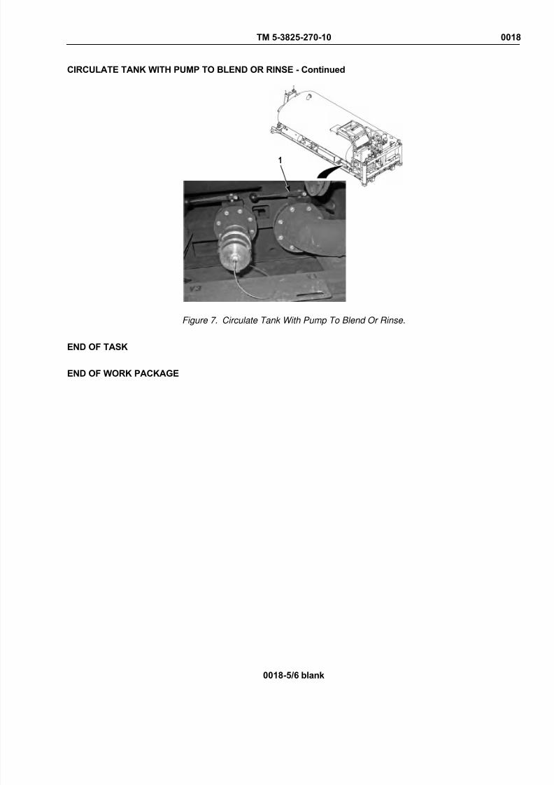
8/6/2019 TM 5-3825-270-10 ENGINEER MISSION MODULE WATER DISTRIBUTION
http://slidepdf.com/reader/full/tm-5-3825-270-10-engineer-mission-module-water-distribution 143/483
CIRCULATE TANK WITH PUMP TO BLEND OR RINSE - Continued
1
Figure 7. Circulate Tank With Pump To Blend Or Rinse.
END OF TASK
END OF WORK PACKAGE
TM 5-3825-270-10 0018
0018-5/6 blank

8/6/2019 TM 5-3825-270-10 ENGINEER MISSION MODULE WATER DISTRIBUTION
http://slidepdf.com/reader/full/tm-5-3825-270-10-engineer-mission-module-water-distribution 144/483
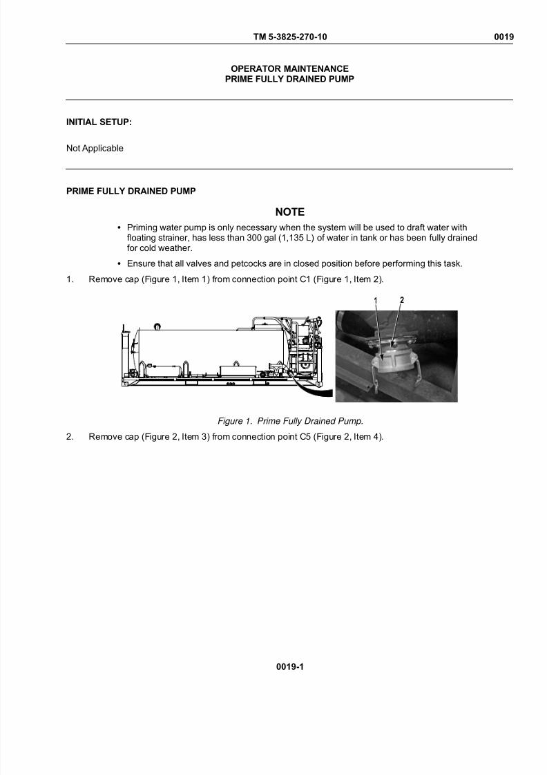
8/6/2019 TM 5-3825-270-10 ENGINEER MISSION MODULE WATER DISTRIBUTION
http://slidepdf.com/reader/full/tm-5-3825-270-10-engineer-mission-module-water-distribution 145/483
OPERATOR MAINTENANCEPRIME FULLY DRAINED PUMP
INITIAL SETUP:
Not Applicable
PRIME FULLY DRAINED PUMP
NOTE
• Priming water pump is only necessary when the system will be used to draft water withfloating strainer, has less than 300 gal (1,135 L) of water in tank or has been fully drainedfor cold weather.
• Ensure that all valves and petcocks are in closed position before performing this task.
1. Remove cap (Figure 1, Item 1) from connection point C1 (Figure 1, Item 2).
21
Figure 1. Prime Fully Drained Pump.
2. Remove cap (Figure 2, Item 3) from connection point C5 (Figure 2, Item 4).
TM 5-3825-270-10 0019
0019-1

8/6/2019 TM 5-3825-270-10 ENGINEER MISSION MODULE WATER DISTRIBUTION
http://slidepdf.com/reader/full/tm-5-3825-270-10-engineer-mission-module-water-distribution 146/483
PRIME FULLY DRAINED PUMP - Continued
3
4
Figure 2. Prime Fully Drained Pump.
3. Prime water pump (Figure 3, Item 5) by pouring five to ten gal (18.9 to 37.8 L) of clean water down prime hose(Figure 3, Item 6) or until water flows from connection point C1 (Figure 3, Item 2).
TM 5-3825-270-10 0019
0019-2
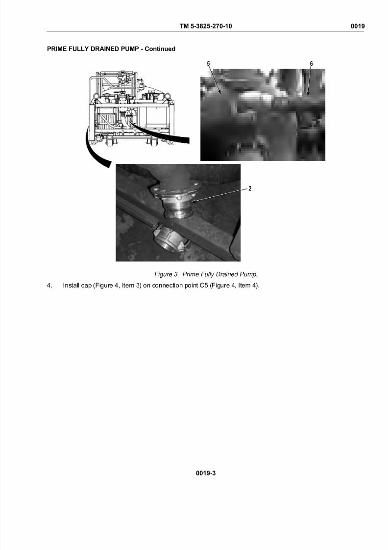
8/6/2019 TM 5-3825-270-10 ENGINEER MISSION MODULE WATER DISTRIBUTION
http://slidepdf.com/reader/full/tm-5-3825-270-10-engineer-mission-module-water-distribution 147/483
PRIME FULLY DRAINED PUMP - Continued
5
2
6
Figure 3. Prime Fully Drained Pump.
4. Install cap (Figure 4, Item 3) on connection point C5 (Figure 4, Item 4).
TM 5-3825-270-10 0019
0019-3
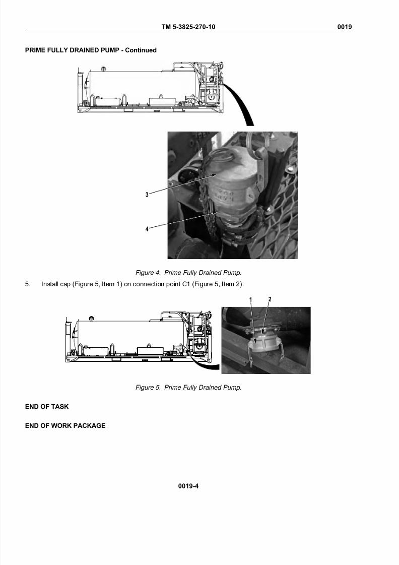
8/6/2019 TM 5-3825-270-10 ENGINEER MISSION MODULE WATER DISTRIBUTION
http://slidepdf.com/reader/full/tm-5-3825-270-10-engineer-mission-module-water-distribution 148/483
PRIME FULLY DRAINED PUMP - Continued
3
4
Figure 4. Prime Fully Drained Pump.
5. Install cap (Figure 5, Item 1) on connection point C1 (Figure 5, Item 2).
21
Figure 5. Prime Fully Drained Pump.
END OF TASK
END OF WORK PACKAGE
TM 5-3825-270-10 0019
0019-4

8/6/2019 TM 5-3825-270-10 ENGINEER MISSION MODULE WATER DISTRIBUTION
http://slidepdf.com/reader/full/tm-5-3825-270-10-engineer-mission-module-water-distribution 149/483
OPERATOR MAINTENANCELOAD TANK AT STRAINER WITH SYSTEM PUMP AND 3" HOSE
INITIAL SETUP:
Not Applicable
LOAD TANK AT STRAINER WITH SYSTEM PUMP AND FLOATING STRAINER
NOTE
Ensure that all valves and petcocks are in closed position before performing this task.
1. Ensure that water pump is primed (WP 0019).
2. Position Water Distributor as close to water source as possible.
NOTE
• Water sources with at least 4 ft depth will allow optimum tank loading performance andfewer problems with air and debris entering floating strainer while loading tank.
• Water sources that are not at least 4 ft deep should be avoided because they will requirereduced pumping rates and more attention to achieve a successful loading mission.
3. Unstow hoses (WP 0078).
4. Unstow floating strainer (WP 0079).
5. Remove cap (Figure 1, Item 2) from floating strainer (Figure 1, Item 1).
2
1
Figure 1. Load Tank At Strainer With System Pump And Floating Strainer.
6. Remove cap(s) (Figure 2, Item 4) from suction hose(s) (Figure 2, Item 3).
TM 5-3825-270-10 0020
0020-1

8/6/2019 TM 5-3825-270-10 ENGINEER MISSION MODULE WATER DISTRIBUTION
http://slidepdf.com/reader/full/tm-5-3825-270-10-engineer-mission-module-water-distribution 150/483
LOAD TANK AT STRAINER WITH SYSTEM PUMP AND FLOATING STRAINER - Continued
3 4
Figure 2. Load Tank At Strainer With System Pump And Floating Strainer.
NOTE
Use of a single suction hose will allow faster loading if water depth and close positioning of water distributor near water source is possible. Use both hoses when strainer must be placedfurther out from edge of water source to find deeper water.
7. Connect suction hose(s) (Figure 3, Item 3) to floating strainer (Figure 3, Item 1).
1
3
Figure 3. Load Tank At Strainer With System Pump And Floating Strainer.
8. Remove cap (Figure 4, Item 5) from connection point C1 (Figure 4, Item 6).
TM 5-3825-270-10 0020
0020-2

8/6/2019 TM 5-3825-270-10 ENGINEER MISSION MODULE WATER DISTRIBUTION
http://slidepdf.com/reader/full/tm-5-3825-270-10-engineer-mission-module-water-distribution 151/483
LOAD TANK AT STRAINER WITH SYSTEM PUMP AND FLOATING STRAINER - Continued
65
Figure 4. Load Tank At Strainer With System Pump And Floating Strainer.
9. Position suction hose (Figure 5, Item 3) and floating strainer (Figure 5, Item 1) in water source. In shallow waconditions, pre-fill hoses with water by holding open end down near water to allow air to escape as water entfrom strainer.
WATER SOURCE
3
1
Figure 5. Load Tank At Strainer With System Pump And Floating Strainer.
10. Route suction hose (Figure 6, Item 3) to water distributor connection point C1 (Figure 6, Item 6) so there is acontinuous increase in hose elevation from the water source and no high spots that present air bubble traps
TM 5-3825-270-10 0020
0020-3

8/6/2019 TM 5-3825-270-10 ENGINEER MISSION MODULE WATER DISTRIBUTION
http://slidepdf.com/reader/full/tm-5-3825-270-10-engineer-mission-module-water-distribution 152/483
LOAD TANK AT STRAINER WITH SYSTEM PUMP AND FLOATING STRAINER - Continued
63
Figure 6. Load Tank At Strainer With System Pump And Floating Strainer.
NOTE
Air must be able to float continuously up suction hose toward water distributor pump whileloading tank to avoid loss of pumping action when accumulated "slugs" of air pull through.
11. Connect suction hose (Figure 6, Item 3) to connection point C1 (Figure 6, Item 6). Before locking connector levers, rotate hose if necessary so floating strainer is level in water rather than tipping sideways.
12. Open valve V5 (Figure 7, Item 7).
TM 5-3825-270-10 0020
0020-4

8/6/2019 TM 5-3825-270-10 ENGINEER MISSION MODULE WATER DISTRIBUTION
http://slidepdf.com/reader/full/tm-5-3825-270-10-engineer-mission-module-water-distribution 153/483
LOAD TANK AT STRAINER WITH SYSTEM PUMP AND FLOATING STRAINER - Continued
7
Figure 7. Load Tank At Strainer With System Pump And Floating Strainer.
13. Open control panel cover (Figure 8, Item 8) by releasing rubber t-handle (Figure 8, Item 9).
98
Figure 8. Load Tank At Strainer With System Pump And Floating Strainer.
14. Pull out emergency stop button (Figure 9, Item 12).
TM 5-3825-270-10 0020
0020-5

8/6/2019 TM 5-3825-270-10 ENGINEER MISSION MODULE WATER DISTRIBUTION
http://slidepdf.com/reader/full/tm-5-3825-270-10-engineer-mission-module-water-distribution 154/483
LOAD TANK AT STRAINER WITH SYSTEM PUMP AND FLOATING STRAINER - Continued
10
14 13
11 12
Figure 9. Load Tank At Strainer With System Pump And Floating Strainer.
CAUTION
• Release engine start/stop switch once engine is started. Failure to comply may result indamage to equipment.
• Do not let engine run more than 5 minutes without circulating water through pump. Failureto comply may result in damage to equipment.
15. Start engine by pressing up and holding the engine start/stop switch (Figure 9, Item 10) until engine is started.
16. Increase engine speed (Figure 9, Item 11) to 1800 RPM by pressing up on rpm switch (Figure 9, Item 14).
17. Once engine RPM (Figure 9, Item 11) is to desired setting press set switch (Figure 9, Item 13).
18. As pump starts to draw water in floating strainer, monitor water pump inlet gauge (Figure 10, Item 15) andoutlet pressure gauge (Figure 10, Item 16) and water strainer. Inlet vacuum should increase to at least 15"Hgand outlet pressure should begin to rise as water is pulled up hose, through pump, and begins to flow in tank.
TM 5-3825-270-10 0020
0020-6
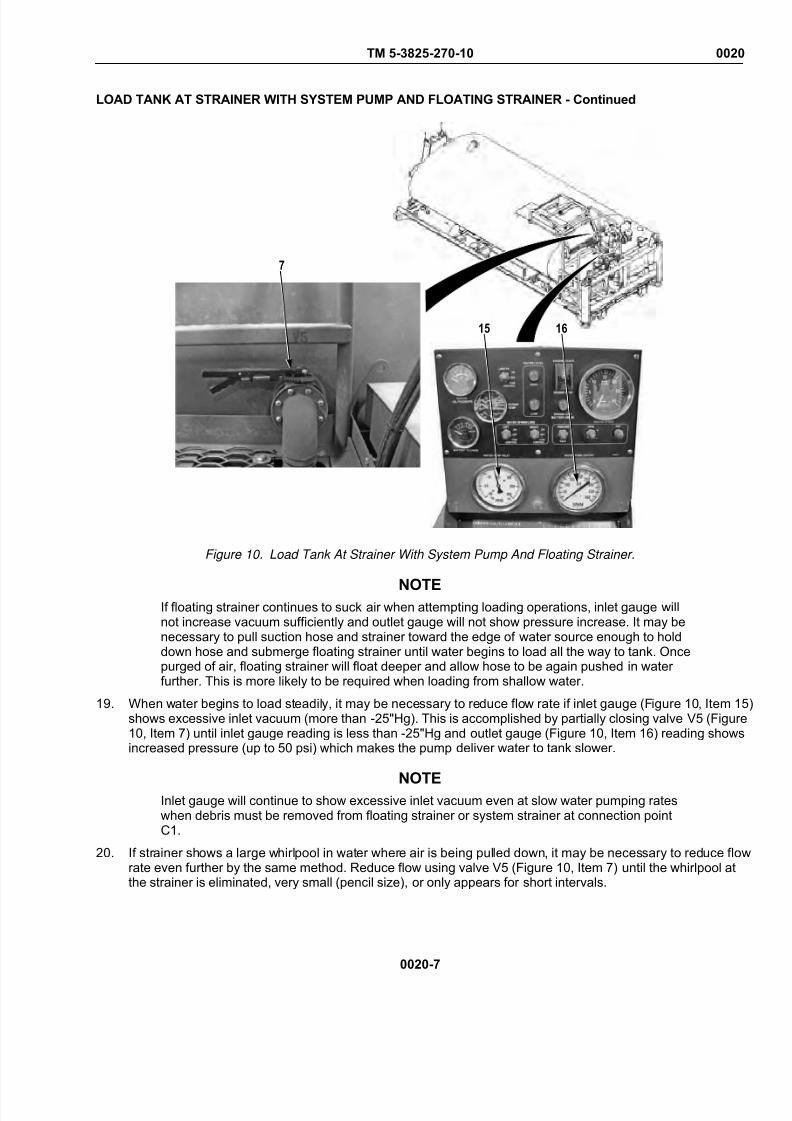
8/6/2019 TM 5-3825-270-10 ENGINEER MISSION MODULE WATER DISTRIBUTION
http://slidepdf.com/reader/full/tm-5-3825-270-10-engineer-mission-module-water-distribution 155/483
LOAD TANK AT STRAINER WITH SYSTEM PUMP AND FLOATING STRAINER - Continued
7
1615
Figure 10. Load Tank At Strainer With System Pump And Floating Strainer.
NOTEIf floating strainer continues to suck air when attempting loading operations, inlet gauge willnot increase vacuum sufficiently and outlet gauge will not show pressure increase. It may benecessary to pull suction hose and strainer toward the edge of water source enough to holddown hose and submerge floating strainer until water begins to load all the way to tank. Oncepurged of air, floating strainer will float deeper and allow hose to be again pushed in water further. This is more likely to be required when loading from shallow water.
19. When water begins to load steadily, it may be necessary to reduce flow rate if inlet gauge (Figure 10, Item 1shows excessive inlet vacuum (more than -25"Hg). This is accomplished by partially closing valve V5 (Figure10, Item 7) until inlet gauge reading is less than -25"Hg and outlet gauge (Figure 10, Item 16) reading showsincreased pressure (up to 50 psi) which makes the pump deliver water to tank slower.
NOTEInlet gauge will continue to show excessive inlet vacuum even at slow water pumping rateswhen debris must be removed from floating strainer or system strainer at connection pointC1.
20. If strainer shows a large whirlpool in water where air is being pulled down, it may be necessary to reduce florate even further by the same method. Reduce flow using valve V5 (Figure 10, Item 7) until the whirlpool atthe strainer is eliminated, very small (pencil size), or only appears for short intervals.
TM 5-3825-270-10 0020
0020-7

8/6/2019 TM 5-3825-270-10 ENGINEER MISSION MODULE WATER DISTRIBUTION
http://slidepdf.com/reader/full/tm-5-3825-270-10-engineer-mission-module-water-distribution 156/483
LOAD TANK AT STRAINER WITH SYSTEM PUMP AND FLOATING STRAINER - Continued
CAUTION
Continuous pump operation with large amounts of air entrainment or excessive inlet vacuumcan lead to pump damage.
21. When loading procedure is complete, press RESUME/IDLE switch (Figure 11, Item 17) to the IDLE positionto return engine rpm (Figure 11, Item 11) to idle speed.
10
14 1317
11 12
Figure 11. Load Tank At Strainer With System Pump And Floating Strainer.
22. Shut water distributor engine off by pressing down on start/stop switch (Figure 11, Item 10).
23. Close valve V5 (Figure 12, Item 7).
TM 5-3825-270-10 0020
0020-8

8/6/2019 TM 5-3825-270-10 ENGINEER MISSION MODULE WATER DISTRIBUTION
http://slidepdf.com/reader/full/tm-5-3825-270-10-engineer-mission-module-water-distribution 157/483
LOAD TANK AT STRAINER WITH SYSTEM PUMP AND FLOATING STRAINER - Continued
7
Figure 12. Load Tank At Strainer With System Pump And Floating Strainer.
24. Push in on emergency stop button (Figure 13, Item 12).
10
14 1317
11 12
Figure 13. Load Tank At Strainer With System Pump And Floating Strainer.
25. Close control panel cover (Figure 14, Item 8) and secure with rubber t-handle (Figure 14, Item 9).
TM 5-3825-270-10 0020
0020-9

8/6/2019 TM 5-3825-270-10 ENGINEER MISSION MODULE WATER DISTRIBUTION
http://slidepdf.com/reader/full/tm-5-3825-270-10-engineer-mission-module-water-distribution 158/483
LOAD TANK AT STRAINER WITH SYSTEM PUMP AND FLOATING STRAINER - Continued
98
Figure 14. Load Tank At Strainer With System Pump And Floating Strainer.
26. Remove suction hose (Figure 15, Item 3) and floating strainer (Figure 15, Item 1) from water source.
WATER SOURCE
3
1
Figure 15. Load Tank At Strainer With System Pump And Floating Strainer.
27. Disconnect suction hose (Figure 16, Item 3) from connection point C1 (Figure 16, Item 6).
TM 5-3825-270-10 0020
0020-10

8/6/2019 TM 5-3825-270-10 ENGINEER MISSION MODULE WATER DISTRIBUTION
http://slidepdf.com/reader/full/tm-5-3825-270-10-engineer-mission-module-water-distribution 159/483
LOAD TANK AT STRAINER WITH SYSTEM PUMP AND FLOATING STRAINER - Continued
63
Figure 16. Load Tank At Strainer With System Pump And Floating Strainer.
28. Back flush (WP 0073) to clean any debris that may have accumulated in connection point C1 (Figure 16, Item6).
29. Install cap (Figure 17, Item 5) on connection point C1 (Figure 17, Item 6).
65
Figure 17. Load Tank At Strainer With System Pump And Floating Strainer.
30. Disconnect suction hose (Figure 18, Item 3) from floating strainer (Figure 18, Item 1).
TM 5-3825-270-10 0020
0020-11
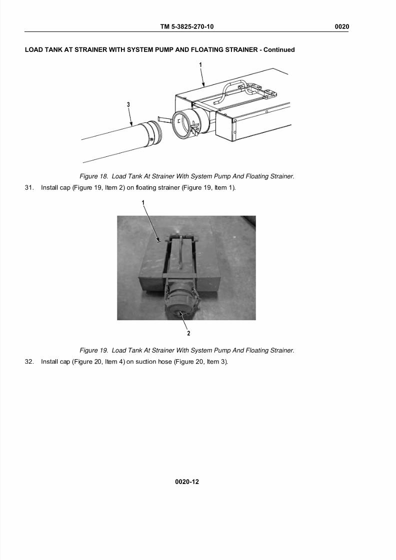
8/6/2019 TM 5-3825-270-10 ENGINEER MISSION MODULE WATER DISTRIBUTION
http://slidepdf.com/reader/full/tm-5-3825-270-10-engineer-mission-module-water-distribution 160/483
LOAD TANK AT STRAINER WITH SYSTEM PUMP AND FLOATING STRAINER - Continued
1
3
Figure 18. Load Tank At Strainer With System Pump And Floating Strainer.
31. Install cap (Figure 19, Item 2) on floating strainer (Figure 19, Item 1).
2
1
Figure 19. Load Tank At Strainer With System Pump And Floating Strainer.
32. Install cap (Figure 20, Item 4) on suction hose (Figure 20, Item 3).
TM 5-3825-270-10 0020
0020-12

8/6/2019 TM 5-3825-270-10 ENGINEER MISSION MODULE WATER DISTRIBUTION
http://slidepdf.com/reader/full/tm-5-3825-270-10-engineer-mission-module-water-distribution 161/483
LOAD TANK AT STRAINER WITH SYSTEM PUMP AND FLOATING STRAINER - Continued
3 4
Figure 20. Load Tank At Strainer With System Pump And Floating Strainer.
33. Stow floating strainer (WP 0079).
34. Stow hoses (WP 0078).
END OF TASK
END OF WORK PACKAGE
TM 5-3825-270-10 0020
0020-13/14 blank

8/6/2019 TM 5-3825-270-10 ENGINEER MISSION MODULE WATER DISTRIBUTION
http://slidepdf.com/reader/full/tm-5-3825-270-10-engineer-mission-module-water-distribution 162/483

8/6/2019 TM 5-3825-270-10 ENGINEER MISSION MODULE WATER DISTRIBUTION
http://slidepdf.com/reader/full/tm-5-3825-270-10-engineer-mission-module-water-distribution 163/483
OPERATOR MAINTENANCELOAD TANK AT STRAINER WITH EXTERNAL PUMP
INITIAL SETUP:
Not Applicable
LOAD TANK AT STRAINER WITH EXTERNAL PUMP
CAUTION
• Do not exceed 50 psi inlet pressure while filling tank at connection point C1. Failure tocomply may result in damage to equipment.
• Do not exceed 600 GPM fill rate from external pressure source. Failure to comply mayresult in damage to equipment.
NOTE
Ensure that all valves and petcocks are in the closed position prior to performing this task.
1. Unstow hoses (WP 0078).
2. Remove cap (Figure 1, Item 3) from connection point C1 (Figure 1, Item 1).
TM 5-3825-270-10 0021
0021-1
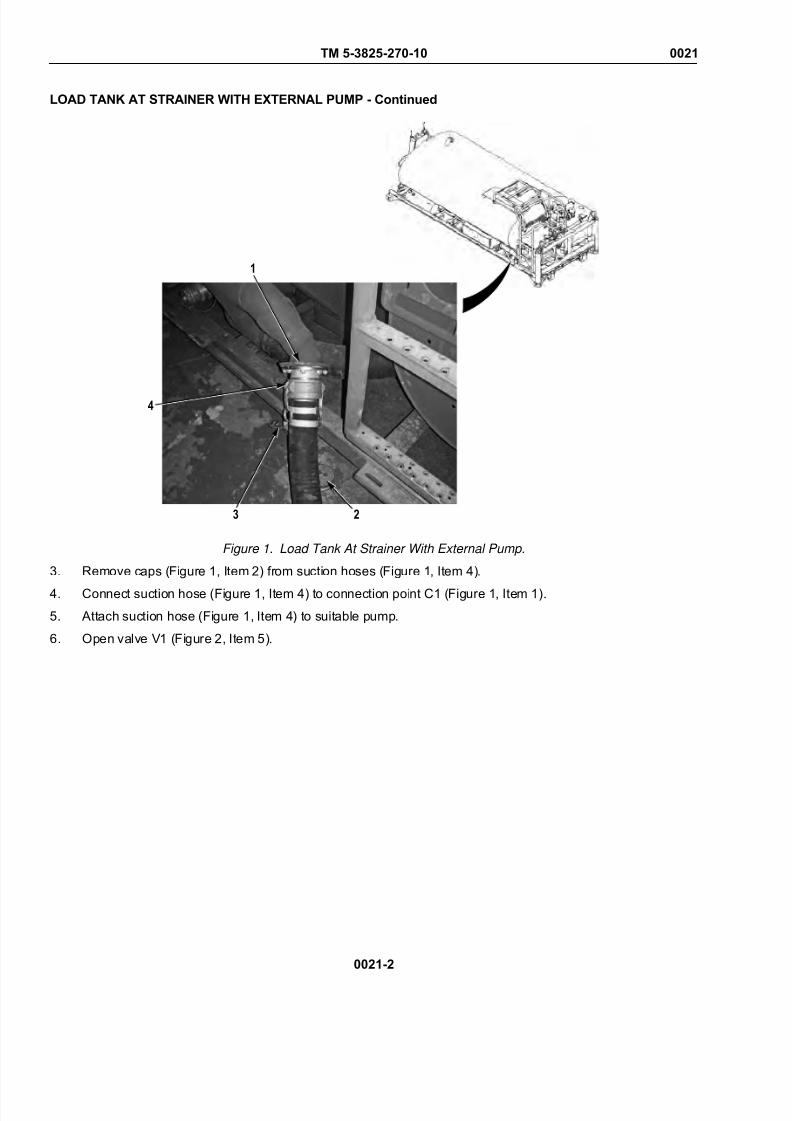
8/6/2019 TM 5-3825-270-10 ENGINEER MISSION MODULE WATER DISTRIBUTION
http://slidepdf.com/reader/full/tm-5-3825-270-10-engineer-mission-module-water-distribution 164/483
LOAD TANK AT STRAINER WITH EXTERNAL PUMP - Continued
1
4
3 2
Figure 1. Load Tank At Strainer With External Pump.
3. Remove caps (Figure 1, Item 2) from suction hoses (Figure 1, Item 4).
4. Connect suction hose (Figure 1, Item 4) to connection point C1 (Figure 1, Item 1).
5. Attach suction hose (Figure 1, Item 4) to suitable pump.
6. Open valve V1 (Figure 2, Item 5).
TM 5-3825-270-10 0021
0021-2
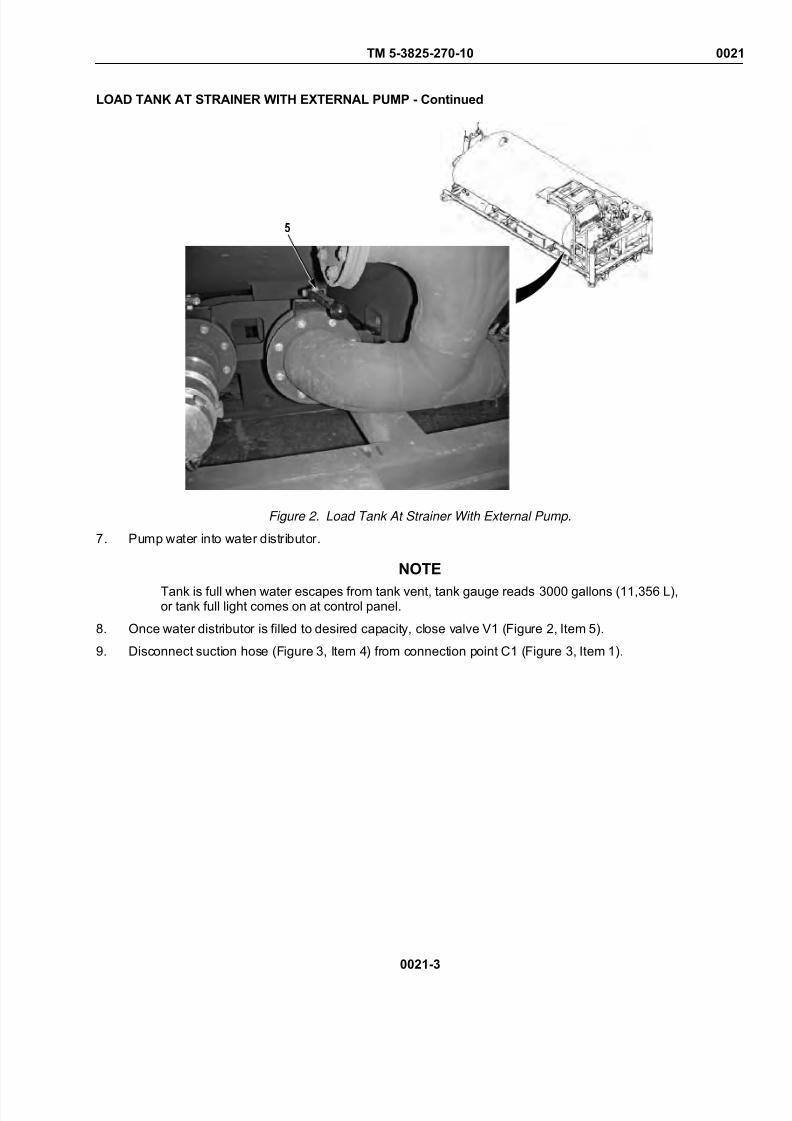
8/6/2019 TM 5-3825-270-10 ENGINEER MISSION MODULE WATER DISTRIBUTION
http://slidepdf.com/reader/full/tm-5-3825-270-10-engineer-mission-module-water-distribution 165/483
LOAD TANK AT STRAINER WITH EXTERNAL PUMP - Continued
5
Figure 2. Load Tank At Strainer With External Pump.
7. Pump water into water distributor.
NOTE
Tank is full when water escapes from tank vent, tank gauge reads 3000 gallons (11,356 L),or tank full light comes on at control panel.
8. Once water distributor is filled to desired capacity, close valve V1 (Figure 2, Item 5).
9. Disconnect suction hose (Figure 3, Item 4) from connection point C1 (Figure 3, Item 1).
TM 5-3825-270-10 0021
0021-3

8/6/2019 TM 5-3825-270-10 ENGINEER MISSION MODULE WATER DISTRIBUTION
http://slidepdf.com/reader/full/tm-5-3825-270-10-engineer-mission-module-water-distribution 166/483
LOAD TANK AT STRAINER WITH EXTERNAL PUMP - Continued
1
4
3 2
Figure 3. Load Tank At Strainer With External Pump.
10. Install caps (Figure 3, Item 2) on suction hoses (Figure 3, Item 4).
11. Install cap (Figure 3, Item 3) on connection point C1 (Figure 3, Item 1).
12. Disconnect suction hose (Figure 3, Item 4) from suitable pump.
13. Stow hoses (WP 0078).
END OF TASK
LOAD TANK AT STRAINER WITH HYDRANT
NOTE
Ensure that all valves and petcocks are in the closed position prior to performing this task.
1. Unstow hoses (WP 0078).2. Ensure that water pump is primed (WP 0019).
3. Remove cap (Figure 4, Item 3) from connection point C1 (Figure 4, Item 1).
TM 5-3825-270-10 0021
0021-4
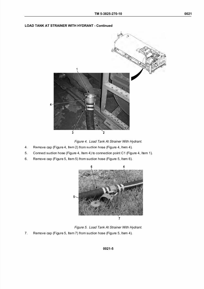
8/6/2019 TM 5-3825-270-10 ENGINEER MISSION MODULE WATER DISTRIBUTION
http://slidepdf.com/reader/full/tm-5-3825-270-10-engineer-mission-module-water-distribution 167/483
LOAD TANK AT STRAINER WITH HYDRANT - Continued
1
4
3 2
Figure 4. Load Tank At Strainer With Hydrant.
4. Remove cap (Figure 4, Item 2) from suction hose (Figure 4, Item 4).
5. Connect suction hose (Figure 4, Item 4) to connection point C1 (Figure 4, Item 1).
6. Remove cap (Figure 5, Item 5) from suction hose (Figure 5, Item 6).
6
5
7
4
Figure 5. Load Tank At Strainer With Hydrant.
7. Remove cap (Figure 5, Item 7) from suction hose (Figure 5, Item 4).
TM 5-3825-270-10 0021
0021-5
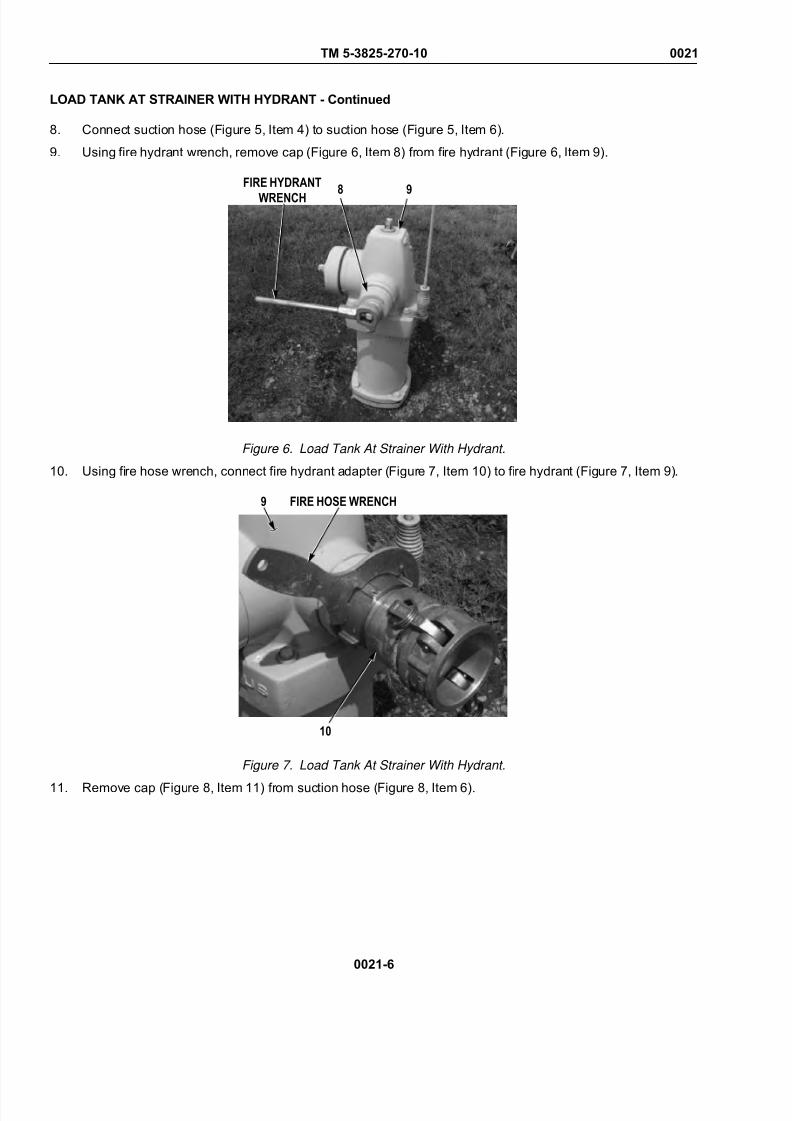
8/6/2019 TM 5-3825-270-10 ENGINEER MISSION MODULE WATER DISTRIBUTION
http://slidepdf.com/reader/full/tm-5-3825-270-10-engineer-mission-module-water-distribution 168/483
LOAD TANK AT STRAINER WITH HYDRANT - Continued
8. Connect suction hose (Figure 5, Item 4) to suction hose (Figure 5, Item 6).
9. Using fire hydrant wrench, remove cap (Figure 6, Item 8) from fire hydrant (Figure 6, Item 9).
98FIRE HYDRANT
WRENCH
Figure 6. Load Tank At Strainer With Hydrant.
10. Using fire hose wrench, connect fire hydrant adapter (Figure 7, Item 10) to fire hydrant (Figure 7, Item 9).
9
10
FIRE HOSE WRENCH
Figure 7. Load Tank At Strainer With Hydrant.
11. Remove cap (Figure 8, Item 11) from suction hose (Figure 8, Item 6).
TM 5-3825-270-10 0021
0021-6

8/6/2019 TM 5-3825-270-10 ENGINEER MISSION MODULE WATER DISTRIBUTION
http://slidepdf.com/reader/full/tm-5-3825-270-10-engineer-mission-module-water-distribution 169/483
LOAD TANK AT STRAINER WITH HYDRANT - Continued
11
6 10
Figure 8. Load Tank At Strainer With Hydrant.
12. Connect suction hose (Figure 8, Item 6) to fire hydrant adapter (Figure 8, Item 10).
13. Open valve V1 (Figure 9, Item 12).
12
Figure 9. Load Tank At Strainer With Hydrant.
TM 5-3825-270-10 0021
0021-7

8/6/2019 TM 5-3825-270-10 ENGINEER MISSION MODULE WATER DISTRIBUTION
http://slidepdf.com/reader/full/tm-5-3825-270-10-engineer-mission-module-water-distribution 170/483
LOAD TANK AT STRAINER WITH HYDRANT - Continued
CAUTION
Hydrant valve must not be opened beyond pressure capability on water distributor connectionC1. Do not exceed 50 psi. Failure to comply may result in damage to equipment.
14. Using fire hydrant wrench, open valve screw (Figure 10, Item 13) on fire hydrant (Figure 10, Item 9) slowly toallow water to flow while watching inlet pressure gauge (Figure 10, Item 14) at control panel.
9
FIRE HYDRANT WRENCH
13
14
Figure 10. Load Tank At Strainer With Hydrant.
15. Close valve V1 (Figure 11, Item 12).
TM 5-3825-270-10 0021
0021-8

8/6/2019 TM 5-3825-270-10 ENGINEER MISSION MODULE WATER DISTRIBUTION
http://slidepdf.com/reader/full/tm-5-3825-270-10-engineer-mission-module-water-distribution 171/483
LOAD TANK AT STRAINER WITH HYDRANT - Continued
12
Figure 11. Load Tank At Strainer With Hydrant.
16. Using fire hydrant wrench, tighten screw (Figure 12, Item 13) on fire hydrant (Figure 12, Item 9) to shut off water flow.
11
10
9
FIRE HYDRANT WRENCH
13
6
Figure 12. Load Tank At Strainer With Hydrant.
17. Disconnect suction hose (Figure 12, Item 6) from fire hydrant adapter (Figure 12, Item 10).
TM 5-3825-270-10 0021
0021-9

8/6/2019 TM 5-3825-270-10 ENGINEER MISSION MODULE WATER DISTRIBUTION
http://slidepdf.com/reader/full/tm-5-3825-270-10-engineer-mission-module-water-distribution 172/483
LOAD TANK AT STRAINER WITH HYDRANT - Continued
18. Install cap (Figure 12, Item 11) on suction hose (Figure 12, Item 6).
19. Using fire hose wrench, remove fire hydrant adapter (Figure 13, Item 10) from fire hydrant (Figure 13, Item 9).
9
10
FIRE HOSE WRENCH
Figure 13. Load Tank At Strainer With Hydrant.
20. Using fire hydrant wrench, install cap (Figure 14, Item 8) on fire hydrant (Figure 14, Item 9).
98FIRE HYDRANT
WRENCH
Figure 14. Load Tank At Strainer With Hydrant.
21. Disconnect suction hose (Figure 15, Item 6) from suction hose (Figure 15, Item 4).
TM 5-3825-270-10 0021
0021-10
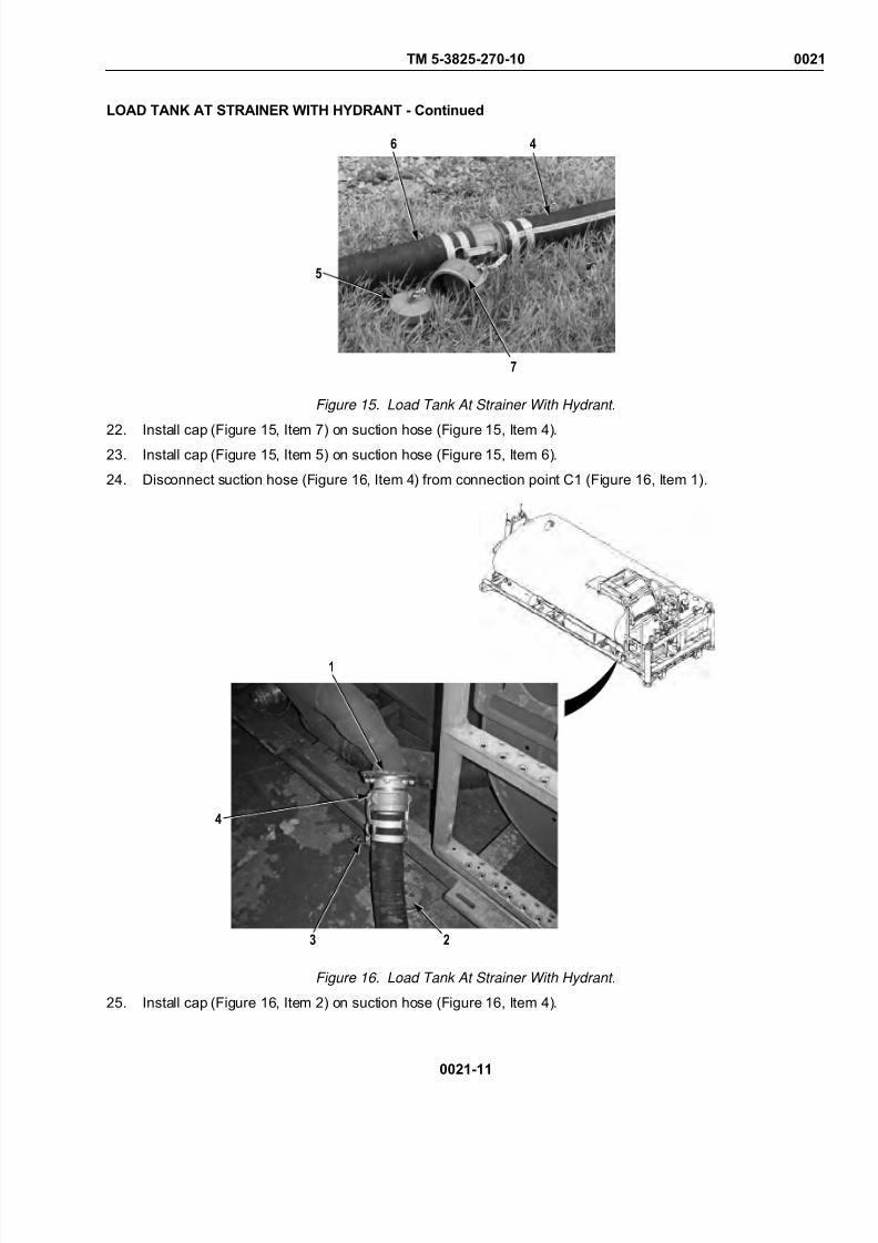
8/6/2019 TM 5-3825-270-10 ENGINEER MISSION MODULE WATER DISTRIBUTION
http://slidepdf.com/reader/full/tm-5-3825-270-10-engineer-mission-module-water-distribution 173/483
LOAD TANK AT STRAINER WITH HYDRANT - Continued
6
5
7
4
Figure 15. Load Tank At Strainer With Hydrant.
22. Install cap (Figure 15, Item 7) on suction hose (Figure 15, Item 4).23. Install cap (Figure 15, Item 5) on suction hose (Figure 15, Item 6).
24. Disconnect suction hose (Figure 16, Item 4) from connection point C1 (Figure 16, Item 1).
1
4
3 2
Figure 16. Load Tank At Strainer With Hydrant.
25. Install cap (Figure 16, Item 2) on suction hose (Figure 16, Item 4).
TM 5-3825-270-10 0021
0021-11

8/6/2019 TM 5-3825-270-10 ENGINEER MISSION MODULE WATER DISTRIBUTION
http://slidepdf.com/reader/full/tm-5-3825-270-10-engineer-mission-module-water-distribution 174/483
LOAD TANK AT STRAINER WITH HYDRANT - Continued
26. Install cap (Figure 16, Item 3) on connection point C1 (Figure 16, Item 1).
27. Stow hoses (WP 0078).
END OF TASK
END OF WORK PACKAGE
TM 5-3825-270-10 0021
0021-12

8/6/2019 TM 5-3825-270-10 ENGINEER MISSION MODULE WATER DISTRIBUTION
http://slidepdf.com/reader/full/tm-5-3825-270-10-engineer-mission-module-water-distribution 175/483
OPERATOR MAINTENANCELOAD TANK WITH EXTERNAL 2.5" AND 5" HOSES
INITIAL SETUP:
Not Applicable
LOAD TANK WITH EXTERNAL 2.5" HOSE
NOTE
• Ensure all valves and petcocks are in the closed position prior to performing this task.
• Connection point C3 or C4 may be used to load tank. Connection point C4 is shown.
1. Remove cap (Figure 1, Item 2) from connection point C4 (Figure 1, Item 3) and attach suitable 2.5" hose.
1
23
Figure 1. Load Tank With External 2.5" Hose.
2. Open valve V4 (Figure 1, Item 1).
TM 5-3825-270-10 0022
0022-1

8/6/2019 TM 5-3825-270-10 ENGINEER MISSION MODULE WATER DISTRIBUTION
http://slidepdf.com/reader/full/tm-5-3825-270-10-engineer-mission-module-water-distribution 176/483
LOAD TANK WITH EXTERNAL 2.5" HOSE - Continued
CAUTION
Do not allow water source to exceed 50 psi (345 kPa). Failure to comply may result in damageto equipment.
3. When loading procedure is complete, close valve V4 (Figure 1, Item 1).4. Disconnect hose from connection point C4 (Figure 1, Item 3) and install cap (Figure 1, Item 2).
END OF TASK
LOAD/UNLOAD TANK WITH 5" HOSE
NOTE
Ensure all valves and petcocks are in the closed position prior to performing this task.
1. Remove cap (Figure 2, Item 1) from connection point C4 (Figure 2, Item 2) and attach suitable 5" hose.
1, 2 3
Figure 2. Load Tank With 5" Hose.
2. Open valve V2 (Figure 2, Item 3).
3. When loading procedure is complete, close valve V2 (Figure 2, Item 3).
TM 5-3825-270-10 0022
0022-2
8/6/2019 TM 5-3825-270-10 ENGINEER MISSION MODULE WATER DISTRIBUTION
http://slidepdf.com/reader/full/tm-5-3825-270-10-engineer-mission-module-water-distribution 177/483
LOAD/UNLOAD TANK WITH 5" HOSE - Continued
4. Disconnect hose from connection point C2 (Figure 2, Item 2) and install cap (Figure 2, Item 1).
END OF TASK
END OF WORK PACKAGE
TM 5-3825-270-10 0022
0022-3/4 blank

8/6/2019 TM 5-3825-270-10 ENGINEER MISSION MODULE WATER DISTRIBUTION
http://slidepdf.com/reader/full/tm-5-3825-270-10-engineer-mission-module-water-distribution 178/483

8/6/2019 TM 5-3825-270-10 ENGINEER MISSION MODULE WATER DISTRIBUTION
http://slidepdf.com/reader/full/tm-5-3825-270-10-engineer-mission-module-water-distribution 179/483
OPERATOR MAINTENANCEEMPTY TANK WITHOUT PUMP
INITIAL SETUP:
Not Applicable
EMPTY TANK WITHOUT PUMP
WARNING
DO NOT stand in the path of the water when draining water from the water distributor. Injuryto personnel could result from the force of the water being discharged from water distributor.
NOTE
Ensure that all valves and petcocks are in the closed position prior to performing this task.
1. Remove connection point C1 cover (Figure 1, Item 1) from strainer inlet (Figure 1, Item 2).
2
34
1
Figure 1. Empty Tank Without Pump.
2. Remove connection point C3 cover (Figure 1, Item 3) from LH tank sump (Figure 1, Item 4).
3. Remove connection point C2 cover (Figure 2, Item 5) from RH tank sump (Figure 2, Item 6).
TM 5-3825-270-10 0023
0023-1

8/6/2019 TM 5-3825-270-10 ENGINEER MISSION MODULE WATER DISTRIBUTION
http://slidepdf.com/reader/full/tm-5-3825-270-10-engineer-mission-module-water-distribution 180/483
EMPTY TANK WITHOUT PUMP - Continued
76 85
Figure 2. Empty Tank Without Pump.4. Remove connection point C4 cover (Figure 2, Item 8) from RH tank sump (Figure 2, Item 7).
5. Open valve V1 (Figure 3, Item 10).
11 129 10
Figure 3. Empty Tank Without Pump.
6. Open valve V3 (Figure 3, Item 9).
7. Open valve V2 (Figure 3, Item 11).
TM 5-3825-270-10 0023
0023-2

8/6/2019 TM 5-3825-270-10 ENGINEER MISSION MODULE WATER DISTRIBUTION
http://slidepdf.com/reader/full/tm-5-3825-270-10-engineer-mission-module-water-distribution 181/483
EMPTY TANK WITHOUT PUMP - Continued
8. Open valve V4 (Figure 3, Item 12).
9. When tank has finished draining, close valve V4 (Figure 3, Item 12).
10. Close valve V2 (Figure 3, Item 11).
11. Close valve V3 (Figure 3, Item 9).
12. Close valve V1 (Figure 3, Item 10).
13. Install connection point C4 cover (Figure 4, Item 8) on RH tank sump (Figure 4, Item 7).
76 85
Figure 4. Empty Tank Without Pump.
14. Install connection point C2 cover (Figure 4, Item 5) on RH tank sump (Figure 4, Item 6).
15. Install connection point C3 cover (Figure 5, Item 3) on LH tank sump (Figure 5, Item 4).
2
34
1
Figure 5. Empty Tank Without Pump.
TM 5-3825-270-10 0023
0023-3

8/6/2019 TM 5-3825-270-10 ENGINEER MISSION MODULE WATER DISTRIBUTION
http://slidepdf.com/reader/full/tm-5-3825-270-10-engineer-mission-module-water-distribution 182/483
EMPTY TANK WITHOUT PUMP - Continued
16. Install connection point C1 cover (Figure 5, Item 1) on strainer inlet (Figure 5, Item 2).
END OF TASK
END OF WORK PACKAGE
TM 5-3825-270-10 0023
0023-4

8/6/2019 TM 5-3825-270-10 ENGINEER MISSION MODULE WATER DISTRIBUTION
http://slidepdf.com/reader/full/tm-5-3825-270-10-engineer-mission-module-water-distribution 183/483
OPERATOR MAINTENANCEFULLY DRAIN SYSTEM FOR COLD WEATHER
INITIAL SETUP:
Not Applicable
FULLY DRAIN SYSTEM FOR COLD WEATHER
NOTE
Ensure that all valves and petcocks are in the closed position prior to performing this task.
1. Load water distributor on PLS truck (WP 0007).
2. Hookup Universal Power Interface Kit (UPIK) (WP 0012).
WARNING
DO NOT stand in the path of the water when draining water from the water distributor. Injuryto personnel could result from the force of the water being discharged from water distributor.
3. Remove connection point C1 cover (Figure 1, Item 1) from strainer inlet (Figure 1, Item 2).
2
34
1
Figure 1. Fully Drain System For Cold Weather.
4. Remove connection point C3 cover (Figure 1, Item 3) from LH tank sump (Figure 1, Item 4).
5. Remove connection point C2 cover (Figure 2, Item 5) from RH tank sump (Figure 2, Item 6).
TM 5-3825-270-10 0024
0024-1

8/6/2019 TM 5-3825-270-10 ENGINEER MISSION MODULE WATER DISTRIBUTION
http://slidepdf.com/reader/full/tm-5-3825-270-10-engineer-mission-module-water-distribution 184/483
FULLY DRAIN SYSTEM FOR COLD WEATHER - Continued
76 85
Figure 2. Fully Drain System For Cold Weather.6. Remove connection point C4 cover (Figure 2, Item 8) from RH tank sump (Figure 2, Item 7).
7. Remove connection point C5 cover (Figure 3, Item 9) from water pump prime hose (Figure 3, Item 10).
9
10
Figure 3. Fully Drain System For Cold Weather.
8. Remove red cap (Figure 4, Item 11) from water turret (Figure 4, Item 12).
TM 5-3825-270-10 0024
0024-2

8/6/2019 TM 5-3825-270-10 ENGINEER MISSION MODULE WATER DISTRIBUTION
http://slidepdf.com/reader/full/tm-5-3825-270-10-engineer-mission-module-water-distribution 185/483
FULLY DRAIN SYSTEM FOR COLD WEATHER - Continued
11
12
Figure 4. Fully Drain System For Cold Weather.
9. Open control panel cover (Figure 5, Item 13) by releasing rubber t-handle (Figure 5, Item 14).
1413
Figure 5. Fully Drain System For Cold Weather.
10. Pull out emergency stop button (Figure 6, Item 15).
TM 5-3825-270-10 0024
0024-3

8/6/2019 TM 5-3825-270-10 ENGINEER MISSION MODULE WATER DISTRIBUTION
http://slidepdf.com/reader/full/tm-5-3825-270-10-engineer-mission-module-water-distribution 186/483
FULLY DRAIN SYSTEM FOR COLD WEATHER - Continued
15
Figure 6. Fully Drain System For Cold Weather.
11. Turn LH sprinkler switch (Figure 7, Item 16) to the ON position.
16 17
Figure 7. Fully Drain System For Cold Weather.
12. Turn RH sprinkler switch (Figure 7, Item 17) to the ON position.
13. Open valve V5 (Figure 8, Item 18).
TM 5-3825-270-10 0024
0024-4
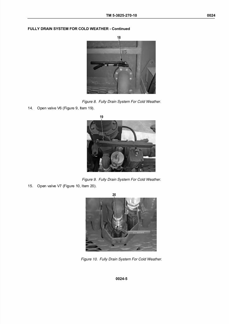
8/6/2019 TM 5-3825-270-10 ENGINEER MISSION MODULE WATER DISTRIBUTION
http://slidepdf.com/reader/full/tm-5-3825-270-10-engineer-mission-module-water-distribution 187/483
FULLY DRAIN SYSTEM FOR COLD WEATHER - Continued
18
Figure 8. Fully Drain System For Cold Weather.
14. Open valve V6 (Figure 9, Item 19).
19
Figure 9. Fully Drain System For Cold Weather.
15. Open valve V7 (Figure 10, Item 20).
20
Figure 10. Fully Drain System For Cold Weather.
TM 5-3825-270-10 0024
0024-5

8/6/2019 TM 5-3825-270-10 ENGINEER MISSION MODULE WATER DISTRIBUTION
http://slidepdf.com/reader/full/tm-5-3825-270-10-engineer-mission-module-water-distribution 188/483
FULLY DRAIN SYSTEM FOR COLD WEATHER - Continued
16. Open valve V1 (Figure 11, Item 22).
2221
Figure 11. Fully Drain System For Cold Weather.
17. Open valve V3 (Figure 11, Item 21).
18. Open valve V8 (Figure 12, Item 23).
TM 5-3825-270-10 0024
0024-6

8/6/2019 TM 5-3825-270-10 ENGINEER MISSION MODULE WATER DISTRIBUTION
http://slidepdf.com/reader/full/tm-5-3825-270-10-engineer-mission-module-water-distribution 189/483
FULLY DRAIN SYSTEM FOR COLD WEATHER - Continued
252423
Figure 12. Fully Drain System For Cold Weather.
19. Open valve V2 (Figure 12, Item 24).
20. Open valve V4 (Figure 12, Item 25).
21. Completely unwind hose reel (WP 0078).
22. Open hose reel nozzle (Figure 13, Item 26).
26
Figure 13. Fully Drain System For Cold Weather.
23. Open four petcock drains (Figure 14, Items 27, 28, 29 and 30).
TM 5-3825-270-10 0024
0024-7

8/6/2019 TM 5-3825-270-10 ENGINEER MISSION MODULE WATER DISTRIBUTION
http://slidepdf.com/reader/full/tm-5-3825-270-10-engineer-mission-module-water-distribution 190/483
FULLY DRAIN SYSTEM FOR COLD WEATHER - Continued
27
29
2830
Figure 14. Fully Drain System For Cold Weather.
24. When tank has finished draining, close four petcock drains (Figure 14, Items 30, 29, 28 and 27).
25. Close hose reel nozzle (Figure 15, Item 26).
26
Figure 15. Fully Drain System For Cold Weather.
26. Wind up hose reel (WP 0078).
27. Close valve V4 (Figure 16, Item 25).
TM 5-3825-270-10 0024
0024-8

8/6/2019 TM 5-3825-270-10 ENGINEER MISSION MODULE WATER DISTRIBUTION
http://slidepdf.com/reader/full/tm-5-3825-270-10-engineer-mission-module-water-distribution 191/483
FULLY DRAIN SYSTEM FOR COLD WEATHER - Continued
252423
Figure 16. Fully Drain System For Cold Weather.
28. Close valve V2 (Figure 16, Item 24).
29. Close valve V8 (Figure 16, Item 23).
30. Close valve V3 (Figure 17, Item 21).
TM 5-3825-270-10 0024
0024-9

8/6/2019 TM 5-3825-270-10 ENGINEER MISSION MODULE WATER DISTRIBUTION
http://slidepdf.com/reader/full/tm-5-3825-270-10-engineer-mission-module-water-distribution 192/483
FULLY DRAIN SYSTEM FOR COLD WEATHER - Continued
2221
Figure 17. Fully Drain System For Cold Weather.
31. Close valve V1 (Figure 17, Item 22).
32. Close valve V7 (Figure 18, Item 20).
20
Figure 18. Fully Drain System For Cold Weather.
33. Close valve V6 (Figure 19, Item 19).
TM 5-3825-270-10 0024
0024-10
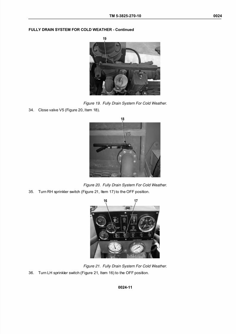
8/6/2019 TM 5-3825-270-10 ENGINEER MISSION MODULE WATER DISTRIBUTION
http://slidepdf.com/reader/full/tm-5-3825-270-10-engineer-mission-module-water-distribution 193/483
FULLY DRAIN SYSTEM FOR COLD WEATHER - Continued
19
Figure 19. Fully Drain System For Cold Weather.
34. Close valve V5 (Figure 20, Item 18).
18
Figure 20. Fully Drain System For Cold Weather.
35. Turn RH sprinkler switch (Figure 21, Item 17) to the OFF position.
16 17
Figure 21. Fully Drain System For Cold Weather.
36. Turn LH sprinkler switch (Figure 21, Item 16) to the OFF position.
TM 5-3825-270-10 0024
0024-11

8/6/2019 TM 5-3825-270-10 ENGINEER MISSION MODULE WATER DISTRIBUTION
http://slidepdf.com/reader/full/tm-5-3825-270-10-engineer-mission-module-water-distribution 194/483
FULLY DRAIN SYSTEM FOR COLD WEATHER - Continued
37. Push in on emergency stop button (Figure 22, Item 15).
15
Figure 22. Fully Drain System For Cold Weather.
38. Close control panel cover (Figure 23, Item 13) and secure with rubber t-handle (Figure 23, Item 14).
1413
Figure 23. Fully Drain System For Cold Weather.
39. Install red cap (Figure 24, Item 11) on water turret (Figure 24, Item 12).
TM 5-3825-270-10 0024
0024-12

8/6/2019 TM 5-3825-270-10 ENGINEER MISSION MODULE WATER DISTRIBUTION
http://slidepdf.com/reader/full/tm-5-3825-270-10-engineer-mission-module-water-distribution 195/483
FULLY DRAIN SYSTEM FOR COLD WEATHER - Continued
11
12
Figure 24. Fully Drain System For Cold Weather.
40. Install connection point C5 cover (Figure 25, Item 9) on water pump prime hose (Figure 25, Item 10).
9
10
Figure 25. Fully Drain System For Cold Weather.
41. Install connection point C4 cover (Figure 26, Item 8) on RH tank sump (Figure 26, Item 7).
TM 5-3825-270-10 0024
0024-13

8/6/2019 TM 5-3825-270-10 ENGINEER MISSION MODULE WATER DISTRIBUTION
http://slidepdf.com/reader/full/tm-5-3825-270-10-engineer-mission-module-water-distribution 196/483
FULLY DRAIN SYSTEM FOR COLD WEATHER - Continued
76 85
Figure 26. Fully Drain System For Cold Weather.42. Install connection point C2 cover (Figure 26, Item 5) on RH tank sump (Figure 26, Item 6).
43. Install connection point C3 cover (Figure 27, Item 3) on LH tank sump (Figure 27, Item 4).
2
34
1
Figure 27. Fully Drain System For Cold Weather.
44. Install connection point C1 cover (Figure 27, Item 1) on strainer inlet (Figure 27, Item 2).
45. Disconnect Universal Power Interface Kit (UPIK) (WP 0012).
46. Unload water distributor from PLS truck (WP 0007).
END OF TASK
END OF WORK PACKAGE
TM 5-3825-270-10 0024
0024-14

8/6/2019 TM 5-3825-270-10 ENGINEER MISSION MODULE WATER DISTRIBUTION
http://slidepdf.com/reader/full/tm-5-3825-270-10-engineer-mission-module-water-distribution 197/483
OPERATOR MAINTENANCEOPERATING IN EXTREME HEAT
INITIAL SETUP:
Not Applicable
OPERATING IN EXTREME HEAT
WARNING
When mission requires the system or unit operator and crew to remain stationary at an areaor location in outside temperatures above 90°F (32°C), operator and crew must observeproper safety precautions to prevent heat stress injury. Refer to FM 21-10,Field Hygiene and Sanitation , and FM 4.25-11, First Aid for Soldiers , for proper precautions and preventive
measures. Failure to comply may result in injury or death to personnel.
NOTE
The water distributor is designed to operate in extreme heat. Water tank is vented to controlthe release of high temperature buildup within the water tank.
1. Monitor engine temperature gauge (WP 0071) closely. If engine temperature gauge reads over 220°F (104°Cshut engine OFF immediately. Engine must be allowed to cool down before restarting.
2. Monitor fluid levels (WP 0071) more frequently.
END OF TASK
END OF WORK PACKAGE
TM 5-3825-270-10 0025
0025-1/2 blank

8/6/2019 TM 5-3825-270-10 ENGINEER MISSION MODULE WATER DISTRIBUTION
http://slidepdf.com/reader/full/tm-5-3825-270-10-engineer-mission-module-water-distribution 198/483

8/6/2019 TM 5-3825-270-10 ENGINEER MISSION MODULE WATER DISTRIBUTION
http://slidepdf.com/reader/full/tm-5-3825-270-10-engineer-mission-module-water-distribution 199/483
OPERATOR MAINTENANCEOPERATING IN EXTREME DUST
INITIAL SETUP:
Not Applicable
OPERATING IN EXTREME DUST
1. Dusty areas will cause buildup within the engine/pump module housing. Ensure that both engine access panare closed at all times.
2. After operation, clean, inspect, and lubricate equipment.
3. Due to the quick buildup of dust, clean, inspect, lubricate equipment, and change the engine oil more frequethan normal.
4. In dusty conditions, because of excessive buildup, it may be necessary to clean and change the engine air filters more often than normal. It is also recommended to clean vents from accumulation of foreign material.
5. Although not perceived to be a big threat, dust can be abrasive and scratch glass-like surfaces. It also caninsulate internal components causing a potential for them to overheat. Thus, it is recommended to keep glaslike surfaces (i.e. control panels) covered as much as possible to prevent scratching, and to clean the water distributor after operating in dusty environments to remove the dust and prevent unforeseen failures.
END OF TASK
END OF WORK PACKAGE
TM 5-3825-270-10 0026
0026-1/2 blank

8/6/2019 TM 5-3825-270-10 ENGINEER MISSION MODULE WATER DISTRIBUTION
http://slidepdf.com/reader/full/tm-5-3825-270-10-engineer-mission-module-water-distribution 200/483

8/6/2019 TM 5-3825-270-10 ENGINEER MISSION MODULE WATER DISTRIBUTION
http://slidepdf.com/reader/full/tm-5-3825-270-10-engineer-mission-module-water-distribution 201/483
OPERATOR MAINTENANCEOPERATING IN COLD ENVIRONMENT +45 DEGREES F TO +33 DEGREES F (+7 DEGREES C TO +1 DEGRE
C)
INITIAL SETUP:
Not Applicable
OPERATING IN COLD ENVIRONMENT
WARNING
• DO NOT touch extremely cold metal. Bare skin may freeze to cold metal. Failure to
comply may result in injury or death to personnel.
• Wear gloves when operating or handling metallic equipment that is wet or ice covered.Failure to comply may result in injury or death to personnel.
• Exercise caution when working on the catwalk where snow or ice exists. Failure to complymay result in injury or death to personnel.
1. 33° F (1° C ) and above. Water Distributor operations can proceed as normal when temperatures are withinthis range.
2. 33° F (1° C ) and below. Fully drain water distributor (WP 0011) after use when temperatures are within thisrange.
3. 31° F (-0.6° C) and below. The water distributor is not meant for use when temperatures are within this rang
END OF TASK
END OF WORK PACKAGE
TM 5-3825-270-10 0027
0027-1/2 blank

8/6/2019 TM 5-3825-270-10 ENGINEER MISSION MODULE WATER DISTRIBUTION
http://slidepdf.com/reader/full/tm-5-3825-270-10-engineer-mission-module-water-distribution 202/483
8/6/2019 TM 5-3825-270-10 ENGINEER MISSION MODULE WATER DISTRIBUTION
http://slidepdf.com/reader/full/tm-5-3825-270-10-engineer-mission-module-water-distribution 203/483
CHAPTER 3
TROUBLESHOOTING PROCEDURES
TM 5-3825-270-10

8/6/2019 TM 5-3825-270-10 ENGINEER MISSION MODULE WATER DISTRIBUTION
http://slidepdf.com/reader/full/tm-5-3825-270-10-engineer-mission-module-water-distribution 204/483

8/6/2019 TM 5-3825-270-10 ENGINEER MISSION MODULE WATER DISTRIBUTION
http://slidepdf.com/reader/full/tm-5-3825-270-10-engineer-mission-module-water-distribution 205/483
OPERATOR MAINTENANCEGENERAL TROUBLESHOOTING INSTRUCTIONS
Troubleshooting Instructions
This work package contains troubleshooting information for locating and correcting some operating troubles whichmay develop with the water distributor. This manual cannot list all possible malfunctions that may occur, nor can itinclude all tests, inspections, and corrective actions. Notify maintenance personnel if a malfunction is not listed,unless a malfunction and cause are obvious or the malfunction can be corrected by a corrective action that is alrealisted.
Battery Troubleshooting. When troubleshooting water distributor batteries ensure to safe guard against electricshock. When using wrench to connect/disconnect battery cables do not allow wrench to contact positive terminaland other metal.
Procedures. The troubleshooting symptom index lists possible malfunctions that may be experienced duringoperation of equipment and components. Each malfunction for an individual component, unit, or system is followeby a list of tests and corrective actions.
Lubrication. When instructions to lubricate, grease, oil, or add oil appear in the troubleshooting table, refer to theField Level Maintenance lubrication chart.
Visual Inspections. When inspecting hoses and lines for damage ensure to also inspect associated fittings for defects.
END OF WORK PACKAGE
TM 5-3825-270-10 0028
0028-1/2 blank

8/6/2019 TM 5-3825-270-10 ENGINEER MISSION MODULE WATER DISTRIBUTION
http://slidepdf.com/reader/full/tm-5-3825-270-10-engineer-mission-module-water-distribution 206/483

8/6/2019 TM 5-3825-270-10 ENGINEER MISSION MODULE WATER DISTRIBUTION
http://slidepdf.com/reader/full/tm-5-3825-270-10-engineer-mission-module-water-distribution 207/483
OPERATOR MAINTENANCETROUBLESHOOTING SYMPTOM INDEX - OPERATOR MAINTENANCE
TROUBLESHOOTING SYMPTOM INDEX
Malfunction/Symptom Troubleshooting Procedure
CONTROL PANEL TROUBLESHOOTING
1. Battery Voltage Gauge Inoperative .......................................WP 0046
2. Battery Voltage Gauge Reads High Or Low .........................WP 0047
3. Engine Off/Battery Drain Indicator Inoperative ......................WP 0048
4. Engine Off/Battery Drain Indicator Stays Illuminated ............WP 0049
5. Engine Oil Pressure Gauge Reads Low ...............................WP 0050
6. Engine Oil Pressure Gauge Reads High ...............................WP 0051
7. No Power to Main Control Panel ...........................................WP 0045
8. Water Level High Indicator Does Not Illuminate ...................WP 0053
9. Water Level High Indicator Stays Illuminated .......................WP 0055
10. Water Level Low Indicator Does Not Illuminate ....................WP 0054
11. Water Level Low Indicator Stays Illuminated ........................WP 0056
12. Water Pump Inlet Gauge Inoperative ....................................WP 0052
ELECTRICAL TROUBLESHOOTING
1. Water Distributor Does Not Operate Remotely .....................WP 0044
2. Work Lights Do Not Operate .................................................WP 0043
ENGINE TROUBLESHOOTING
1. Engine Cranks But Does Not Start ........................................WP 0031
2. Engine Does Not Crank ........................................................WP 0030
3. Engine Overheats .................................................................WP 0036
4. Engine Stalls .........................................................................WP 0032
5. Engine Will Not Increase RPM ..............................................WP 0033
6. Excessive Engine Noise ........................................................WP 0035
7. Excessive Engine Vibration ...................................................WP 0034
EXHAUST TROUBLESHOOTING
1. Abnormal Exhaust .................................................................WP 0037
TM 5-3825-270-10 0029
0029-1

8/6/2019 TM 5-3825-270-10 ENGINEER MISSION MODULE WATER DISTRIBUTION
http://slidepdf.com/reader/full/tm-5-3825-270-10-engineer-mission-module-water-distribution 208/483
TROUBLESHOOTING SYMPTOM INDEX - Continued
Malfunction/Symptom Troubleshooting Procedure
PUMP TROUBLESHOOTING
1. Excessive Pump Noise .........................................................WP 0042
2. Excessive Water Pressure ....................................................WP 0039
3. Water Pump Does Not Operate ............................................WP 0038
4. Water Pressure Erratic ..........................................................WP 0041
5. Water Pressure Low ..............................................................WP 0040
WATER STATION TROUBLESHOOTING
1. Gravity Fed Sprinkler Bar Does Not Operate ........................WP 0059
2. Gravity Fed Sprinkler Bar Stream Low ..................................WP 0060
3. Sprinkler Head Pressure Low ...............................................WP 0062
4. Sprinkler Heads Do Not Operate ..........................................WP 0061
5. Manual Water Turret Does Not Operate ...............................WP 0057
6. Manual Water Turret Pressure Low ......................................WP 0058
7. Water Hose Inoperative ........................................................WP 0063
8. Water Hose Pressure Low ....................................................WP 0064
END OF WORK PACKAGE
TM 5-3825-270-10 0029
0029-2

8/6/2019 TM 5-3825-270-10 ENGINEER MISSION MODULE WATER DISTRIBUTION
http://slidepdf.com/reader/full/tm-5-3825-270-10-engineer-mission-module-water-distribution 209/483
OPERATOR MAINTENANCEENGINE DOES NOT CRANK
INITIAL SETUP:
ReferencesOpen/Close Battery Box Cover (WP 0081)
References (cont.)Operator Preventive Maintenance Checks And
Services (PMCS) (WP 0071)Discharge From Hose Reel Assembly (WP 0017)
Equipment ConditionEngine OFF. (WP 0017)
TROUBLESHOOTING PROCEDUREENGINE DOES NOT CRANK
STEP 1Is EMERGENCY STOP switch rotated to on position and ENGINE OFF/BATTERY DRAIN indicator illuminated?
NOTE
Engine will not start and water distributor will not have power if emergency stop switch ispushed in to the off position.
1. Verify EMERGENCY STOP switch position.
EMERGENCY STOP SWITCH
Figure 1. Emergency Stop Switch - Step 1.
2. Observe ENGINE OFF/BATTERY DRAIN indicator.
TM 5-3825-270-10 0030
0030-1

8/6/2019 TM 5-3825-270-10 ENGINEER MISSION MODULE WATER DISTRIBUTION
http://slidepdf.com/reader/full/tm-5-3825-270-10-engineer-mission-module-water-distribution 210/483
ENGINE OFF / BATTERY
DRAIN INDICATOR
Figure 2. Engine Off/Battery Drain Indicator - Step 1.
CONDITION/INDICATIONIs EMERGENCY STOP switch rotated to on position and ENGINE OFF/BATTERY DRAIN indicator illuminated?
DECISIONNo - Rotate emergency stop switch to on position. Verify problem is solved. (Step 5 - Does engine crank?)Yes - Go to step 2. (Step 2 - Is 15-amp circuit breaker tripped?)
STEP 2Is 15-amp circuit breaker tripped?
NOTE
The 15-amp circuit breaker works in conjunction with the emergency stop switch to controlpower to the control panel. If a power surge is detected, the 15-amp circuit breaker will tripprohibiting the emergency stop switch to supply power to the control panel and engine.
Verify 15-amp circuit breaker position.
15-AMP
CIRCUIT
BREAKER
Figure 3. 15-Amp Circuit Breaker - Step 2.
CONDITION/INDICATIONIs 15-amp circuit breaker tripped?
TM 5-3825-270-10 0030
0030-2

8/6/2019 TM 5-3825-270-10 ENGINEER MISSION MODULE WATER DISTRIBUTION
http://slidepdf.com/reader/full/tm-5-3825-270-10-engineer-mission-module-water-distribution 211/483
DECISIONNo - Go to step 3. (Step 3 - Are batteries properly connected and free of corrosion?)Yes - Reset 15-amp circuit breaker. Verify problem is solved. (Step 5 - Does engine crank?) If 15 amp circuitbreaker trips again after reset, do not attempt to reset. Notify maintenance personnel 15-amp circuit breaker istripped.
STEP 3Are batteries properly connected and free of corrosion?1. Remove battery box cover. (WP 0081)2. Visually inspect batteries and battery cables to ensure proper connection and corrosion.
BATTERY
CABLES
BATTERIES
Figure 4. Batteries And Battery Cables - Step 3.
CONDITION/INDICATIONAre batteries properly connected and free of corrosion?
DECISIONNo - Notify maintenance personnel to properly clean battery terminals and/or connect battery cables. Verifyproblem is solved. (Step 5 - Does engine crank?)Yes - Go to step 4. (Step 4 - Does engine crank when slaved?)
STEP 4Does engine crank when slaved?
If available, attempt to slave start engine with donor vehicle or portable starting aid.
CONDITION/INDICATION
Does engine crank when slaved?
DECISIONNo - Notify maintenance personnel engine does not crank.Yes - Notify maintenance personnel batteries require servicing.
STEP 5Does engine crank?
Attempt to start engine. (WP 0017)
TM 5-3825-270-10 0030
0030-3

8/6/2019 TM 5-3825-270-10 ENGINEER MISSION MODULE WATER DISTRIBUTION
http://slidepdf.com/reader/full/tm-5-3825-270-10-engineer-mission-module-water-distribution 212/483
CONDITION/INDICATIONDoes engine crank?
DECISIONNo - Problem not found. Notify maintenance personnel engine does not crank.Yes - Problem is solved.
END OF WORK PACKAGE
TM 5-3825-270-10 0030
0030-4

8/6/2019 TM 5-3825-270-10 ENGINEER MISSION MODULE WATER DISTRIBUTION
http://slidepdf.com/reader/full/tm-5-3825-270-10-engineer-mission-module-water-distribution 213/483
OPERATOR MAINTENANCEENGINE CRANKS BUT DOES NOT START
INITIAL SETUP:
ReferencesDischarge From Hose Reel Assembly (WP 0017)
References (cont.)Fueling (WP 0008)Operator Preventive Maintenance Checks And
Services (PMCS) (WP 0071)
Equipment ConditionEngine OFF. (WP 0017)
TROUBLESHOOTING PROCEDUREENGINE CRANKS BUT DOES NOT START
STEP 1Is ambient air cold or has water distributor not been started for a long period of time?
NOTE
The water distributor is equipped with engine glow plugs to help warm engine fuel for starting.If ambient temperature is or has recently been approximately 32° F (0° C), multiple attemptsat starting engine may be necessary.
Attempt to start engine by holding engine start switch to ENGINE START position for no longer than 15 secoat a time. (WP 0017)
CONDITION/INDICATIONIs ambient air cold or has water distributor not been started for a long period of time?
DECISIONNo - Go to step 2. (Step 2 - Does water distributor have enough fuel to start engine?)Yes - Problem solved.
STEP 2Does water distributor have enough fuel to start engine?
Visually inspect inside fuel tank for presence of fuel.
TM 5-3825-270-10 0031
0031-1

8/6/2019 TM 5-3825-270-10 ENGINEER MISSION MODULE WATER DISTRIBUTION
http://slidepdf.com/reader/full/tm-5-3825-270-10-engineer-mission-module-water-distribution 214/483
FUEL TANK
Figure 1. Fuel Tank - Step 2.
CONDITION/INDICATIONDoes water distributor have enough fuel to start engine?
DECISIONNo - Fill with fuel. (WP 0008) Verify problem is solved. (Step 5 - Does engine start?)Yes - Go to step 3. (Step 3 - Does air filter restriction indicator indicate restriction?)
STEP 3Does air filter restriction indicator indicate restriction?
Visually check air filter restriction indicator.
AIR FILTERRESTRICTION INDICATOR
Figure 2. Air Filter Restriction Indicator - Step 3.
CONDITION/INDICATIONDoes air filter restriction indicator indicate restriction?
DECISIONNo - Go to step 4. (Step 4 - Does engine start when slaved?)Yes - Check for air restrictions and ensure air filter is clean and serviceable. (WP 0071) After removal of restrictionand/or cleaning of air filter, reset air restriction indicator. Verify problem is solved. (Step 5 - Does enginestart?)
TM 5-3825-270-10 0031
0031-2

8/6/2019 TM 5-3825-270-10 ENGINEER MISSION MODULE WATER DISTRIBUTION
http://slidepdf.com/reader/full/tm-5-3825-270-10-engineer-mission-module-water-distribution 215/483
STEP 4Does engine start when slaved?
If available, attempt to slave start engine with donor vehicle or portable starting aid.
CONDITION/INDICATIONDoes engine start when slaved?
DECISIONNo - Notify maintenance personnel engine cranks but does not start.Yes - Notify maintenance personnel to service batteries.
STEP 5Does engine start?
Attempt to start engine. (WP 0017)
CONDITION/INDICATIONDoes engine start?
DECISIONNo - Problem not found. Notify maintenance personnel engine cranks but does not start.Yes - Problem is solved.
END OF WORK PACKAGE
TM 5-3825-270-10 0031
0031-3/4 blank

8/6/2019 TM 5-3825-270-10 ENGINEER MISSION MODULE WATER DISTRIBUTION
http://slidepdf.com/reader/full/tm-5-3825-270-10-engineer-mission-module-water-distribution 216/483

8/6/2019 TM 5-3825-270-10 ENGINEER MISSION MODULE WATER DISTRIBUTION
http://slidepdf.com/reader/full/tm-5-3825-270-10-engineer-mission-module-water-distribution 217/483
OPERATOR MAINTENANCEENGINE STALLS
INITIAL SETUP:
ReferencesOperator Preventive Maintenance Checks And
Services (PMCS) (WP 0071)
References (cont.)Fueling (WP 0008)Discharge From Hose Reel Assembly (WP 0017)
Equipment ConditionEngine OFF. (WP 0017)
TROUBLESHOOTING PROCEDUREENGINE STALLS
STEP 1Does water distributor have enough fuel to operate engine?
Visually inspect inside fuel tank for presence of fuel.
FUEL TANK
Figure 1. Fuel Tank - Step 1.
CONDITION/INDICATIONDoes water distributor have enough fuel to operate engine?
DECISIONNo - Fill with fuel. (WP 0008) Verify problem is solved. (Step 3 - Does engine operate normally?)Yes - Go to step 2. (Step 2 - Does air filter restriction indicator indicate restriction?)
STEP 2Does air filter restriction indicator indicate restriction?
Visually check air filter restriction indicator.
TM 5-3825-270-10 0032
0032-1

8/6/2019 TM 5-3825-270-10 ENGINEER MISSION MODULE WATER DISTRIBUTION
http://slidepdf.com/reader/full/tm-5-3825-270-10-engineer-mission-module-water-distribution 218/483
AIR FILTER
RESTRICTION INDICATOR
Figure 2. Air Filter Restriction Indicator - Step 2.
CONDITION/INDICATIONDoes air filter restriction indicator indicate restriction?
DECISION
No - Problem not found. Notify maintenance personnel engine stalls.Yes - Ensure air filter is serviceable (WP 0071) and check for air restrictions. After removal of restriction and/or cleaning of air filter, reset air restriction indicator. Verify problem is solved. (Step 3 - Does engine operatenormally?)
STEP 3Does engine operate normally?
Start and operate engine while observing performance. (WP 0017)
CONDITION/INDICATIONDoes engine operate normally?
DECISION
No - Problem not found. Notify maintenance personnel engine stalls.Yes - Problem is solved.
END OF WORK PACKAGE
TM 5-3825-270-10 0032
0032-2

8/6/2019 TM 5-3825-270-10 ENGINEER MISSION MODULE WATER DISTRIBUTION
http://slidepdf.com/reader/full/tm-5-3825-270-10-engineer-mission-module-water-distribution 219/483
OPERATOR MAINTENANCEENGINE WILL NOT INCREASE RPM
INITIAL SETUP:
ReferencesLocations And Use Of Controls And Indicators
(WP 0004)
Equipment ConditionEngine ON. (WP 0017)
TROUBLESHOOTING PROCEDUREENGINE WILL NOT INCREASE RPM
STEP 1Is water distributor operated by using main control panel, or cab control box?
Determine mode of operation.
MAIN CONTROL PANEL
CAB CONTROL BOX
Figure 1. Main Control Panel And Cab Control Box.
CONDITION/INDICATIONIs water distributor operated by using main control panel, or cab control box?
DECISIONOperated by main control panel - Notify maintenance personnel engine does not increase RPM.Operated remotely - Go to Water Distributor Does Not Operate Remotely. (WP 0044)
END OF WORK PACKAGE
TM 5-3825-270-10 0033
0033-1/2 blank

8/6/2019 TM 5-3825-270-10 ENGINEER MISSION MODULE WATER DISTRIBUTION
http://slidepdf.com/reader/full/tm-5-3825-270-10-engineer-mission-module-water-distribution 220/483
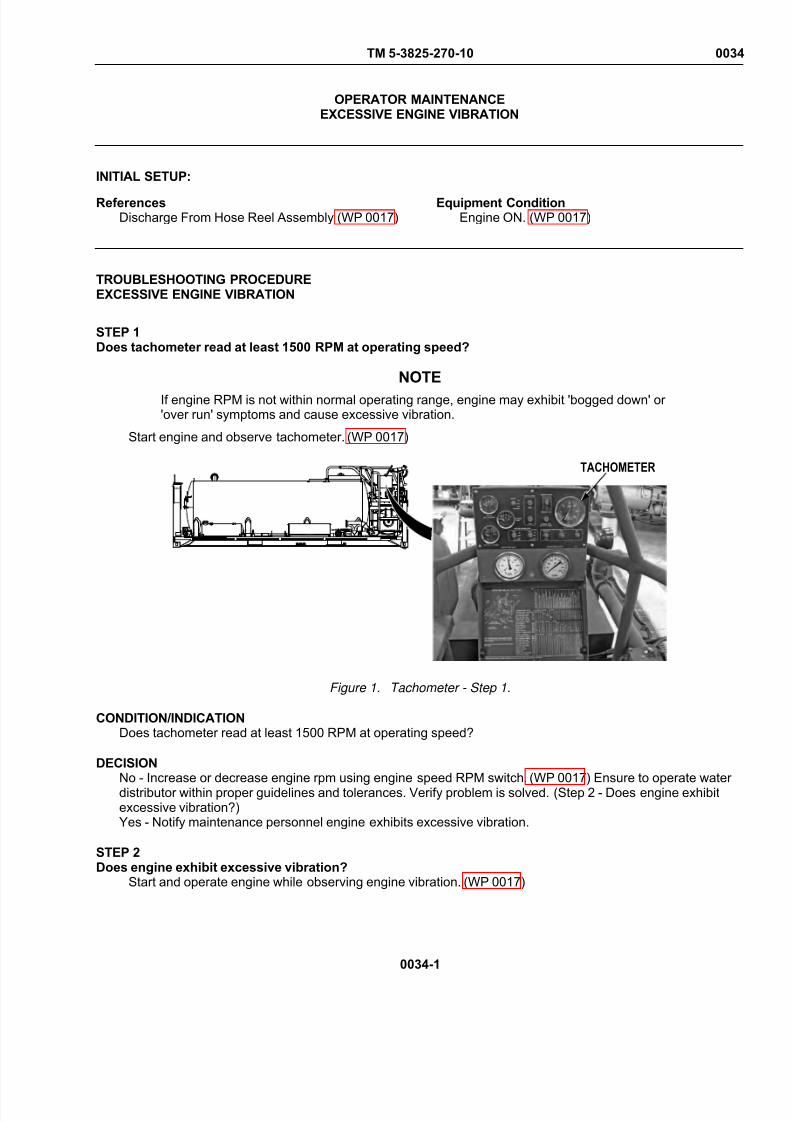
8/6/2019 TM 5-3825-270-10 ENGINEER MISSION MODULE WATER DISTRIBUTION
http://slidepdf.com/reader/full/tm-5-3825-270-10-engineer-mission-module-water-distribution 221/483
OPERATOR MAINTENANCEEXCESSIVE ENGINE VIBRATION
INITIAL SETUP:
ReferencesDischarge From Hose Reel Assembly (WP 0017)
Equipment ConditionEngine ON. (WP 0017)
TROUBLESHOOTING PROCEDUREEXCESSIVE ENGINE VIBRATION
STEP 1Does tachometer read at least 1500 RPM at operating speed?
NOTE
If engine RPM is not within normal operating range, engine may exhibit 'bogged down' or 'over run' symptoms and cause excessive vibration.
Start engine and observe tachometer. (WP 0017)
TACHOMETER
Figure 1. Tachometer - Step 1.
CONDITION/INDICATIONDoes tachometer read at least 1500 RPM at operating speed?
DECISIONNo - Increase or decrease engine rpm using engine speed RPM switch. (WP 0017) Ensure to operate water distributor within proper guidelines and tolerances. Verify problem is solved. (Step 2 - Does engine exhibitexcessive vibration?)Yes - Notify maintenance personnel engine exhibits excessive vibration.
STEP 2Does engine exhibit excessive vibration?
Start and operate engine while observing engine vibration. (WP 0017)
TM 5-3825-270-10 0034
0034-1

8/6/2019 TM 5-3825-270-10 ENGINEER MISSION MODULE WATER DISTRIBUTION
http://slidepdf.com/reader/full/tm-5-3825-270-10-engineer-mission-module-water-distribution 222/483
CONDITION/INDICATIONDoes engine exhibit excessive vibration?
DECISIONNo - Problem is solved.Yes - Problem not found. Notify maintenance personnel engine exhibits excessive vibration.
END OF WORK PACKAGE
TM 5-3825-270-10 0034
0034-2

8/6/2019 TM 5-3825-270-10 ENGINEER MISSION MODULE WATER DISTRIBUTION
http://slidepdf.com/reader/full/tm-5-3825-270-10-engineer-mission-module-water-distribution 223/483
OPERATOR MAINTENANCEEXCESSIVE ENGINE NOISE
INITIAL SETUP:
ReferencesOperator Preventive Maintenance Checks And
Services (PMCS) (WP 0071)Discharge From Hose Reel Assembly (WP 0017)
Equipment ConditionEngine OFF. (WP 0017)
TROUBLESHOOTING PROCEDUREEXCESSIVE ENGINE NOISE
STEP 1Are engine oil and coolant at appropriate levels?
Refer to preventive maintenance checks and services (PMCS) to ensure engine is serviced with proper leveof oil and coolant. (WP 0071)
CONDITION/INDICATIONAre engine oil and coolant at appropriate levels?
DECISIONNo - Service engine with appropriate engine oil and/or coolant. (WP 0071) Verify problem is solved. (Step 2 -Does engine exhibit excessive noise?)Yes - Notify maintenance personnel engine exhibits excessive noise.
STEP 2Does engine exhibit excessive noise?
Start and operate engine while listening for excessive engine noise. (WP 0017)
CONDITION/INDICATIONDoes engine exhibit excessive noise?
DECISIONNo - Problem is solved.Yes - Problem not found. Notify maintenance personnel engine exhibits excessive noise.
END OF WORK PACKAGE
TM 5-3825-270-10 0035
0035-1/2 blank

8/6/2019 TM 5-3825-270-10 ENGINEER MISSION MODULE WATER DISTRIBUTION
http://slidepdf.com/reader/full/tm-5-3825-270-10-engineer-mission-module-water-distribution 224/483
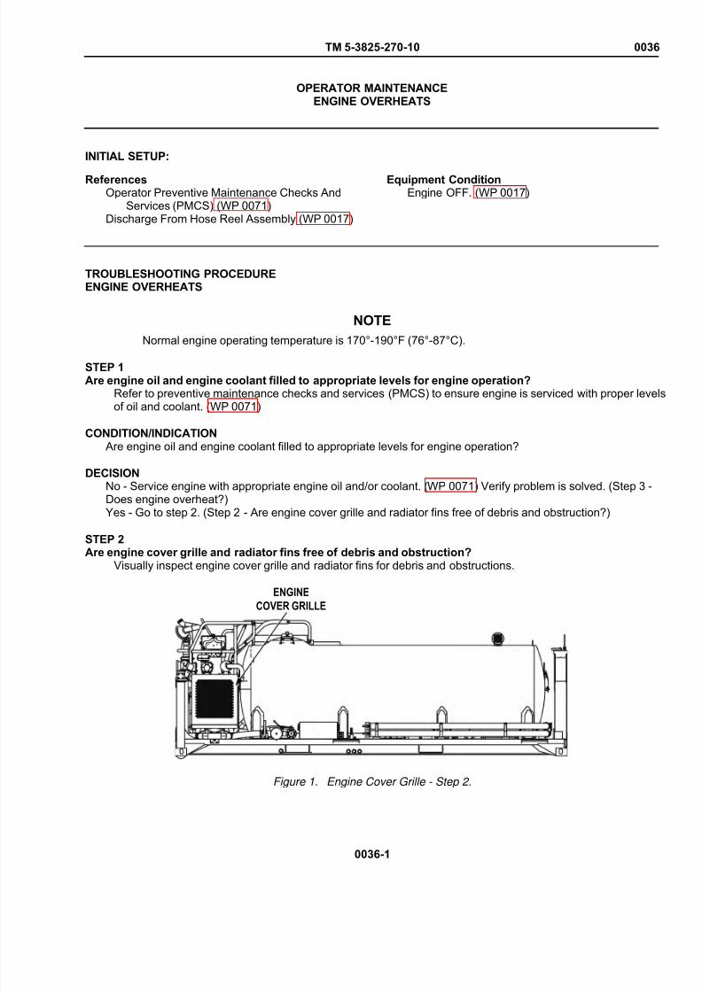
8/6/2019 TM 5-3825-270-10 ENGINEER MISSION MODULE WATER DISTRIBUTION
http://slidepdf.com/reader/full/tm-5-3825-270-10-engineer-mission-module-water-distribution 225/483
OPERATOR MAINTENANCEENGINE OVERHEATS
INITIAL SETUP:
ReferencesOperator Preventive Maintenance Checks And
Services (PMCS) (WP 0071)Discharge From Hose Reel Assembly (WP 0017)
Equipment ConditionEngine OFF. (WP 0017)
TROUBLESHOOTING PROCEDUREENGINE OVERHEATS
NOTE
Normal engine operating temperature is 170°-190°F (76°-87°C).
STEP 1Are engine oil and engine coolant filled to appropriate levels for engine operation?
Refer to preventive maintenance checks and services (PMCS) to ensure engine is serviced with proper leveof oil and coolant. (WP 0071)
CONDITION/INDICATIONAre engine oil and engine coolant filled to appropriate levels for engine operation?
DECISIONNo - Service engine with appropriate engine oil and/or coolant. (WP 0071) Verify problem is solved. (Step 3 -Does engine overheat?)Yes - Go to step 2. (Step 2 - Are engine cover grille and radiator fins free of debris and obstruction?)
STEP 2Are engine cover grille and radiator fins free of debris and obstruction?
Visually inspect engine cover grille and radiator fins for debris and obstructions.
ENGINE
COVER GRILLE
Figure 1. Engine Cover Grille - Step 2.
TM 5-3825-270-10 0036
0036-1

8/6/2019 TM 5-3825-270-10 ENGINEER MISSION MODULE WATER DISTRIBUTION
http://slidepdf.com/reader/full/tm-5-3825-270-10-engineer-mission-module-water-distribution 226/483
CONDITION/INDICATIONAre engine cover grille and radiator fins free of debris and obstruction?
DECISIONNo - Remove debris and restrictions from radiator and/or engine cover grille. Verify problem is solved. (Step 3- Does engine overheat?)Yes - Problem not found. Notify maintenance personnel engine overheats.
STEP 3Does engine overheat?
NOTE
An overheating condition exist if ENGINE TEMP gauge reaches 220°F (104°C) or above.
Start and operate engine while observing ENGINE TEMP gauge. (WP 0017)
CONDITION/INDICATIONDoes engine overheat?
DECISIONNo - Problem is solved.Yes - Problem not found. Notify maintenance personnel engine overheats.
END OF WORK PACKAGE
TM 5-3825-270-10 0036
0036-2

8/6/2019 TM 5-3825-270-10 ENGINEER MISSION MODULE WATER DISTRIBUTION
http://slidepdf.com/reader/full/tm-5-3825-270-10-engineer-mission-module-water-distribution 227/483
OPERATOR MAINTENANCEABNORMAL EXHAUST
INITIAL SETUP:
ReferencesDischarge From Hose Reel Assembly (WP 0017)
Equipment ConditionEngine ON. (WP 0017)
TROUBLESHOOTING PROCEDUREABNORMAL EXHAUST
STEP 1Does engine exhibit abnormal exhaust under normal operating conditions?
NOTE
Diesel engines may exhibit abnormal exhaust color under normal operating conditions atengine start up if the following conditions exists:
• Ambient temperature is, or has recently been, approximately 32° F (0° C).
• Engine has not been started for a long period of time.
• Recent maintenance activity on engine components.
1. Contact maintenance personnel and/or request maintenance records to verify if engine has recently hadmaintenance.
2. Verify if engine has not been started for a long period of time, or ambient temperature is, or has been,approximately 32° F (0° C).
3. Start engine and observe exhaust after three to five minutes of run time. (WP 0017)
CONDITION/INDICATIONDoes engine exhibit abnormal exhaust under normal operating conditions?
DECISIONNo - Problem solved.Yes - Problem not found. Notify maintenance personnel engine exhibits abnormal exhaust.
END OF WORK PACKAGE
TM 5-3825-270-10 0037
0037-1/2 blank

8/6/2019 TM 5-3825-270-10 ENGINEER MISSION MODULE WATER DISTRIBUTION
http://slidepdf.com/reader/full/tm-5-3825-270-10-engineer-mission-module-water-distribution 228/483

8/6/2019 TM 5-3825-270-10 ENGINEER MISSION MODULE WATER DISTRIBUTION
http://slidepdf.com/reader/full/tm-5-3825-270-10-engineer-mission-module-water-distribution 229/483
OPERATOR MAINTENANCEWATER PUMP DOES NOT OPERATE
INITIAL SETUP:
ReferencesDischarge From Hose Reel Assembly (WP 0017)Prime Fully Drained Pump (WP 0019)
Equipment ConditionEngine OFF. (WP 0017)
TROUBLESHOOTING PROCEDUREWATER PUMP DOES NOT OPERATE
STEP 1Is water pump properly primed and ready for operation?
CAUTIONWater pump is mechanically connected to engine and must be primed prior to engine start.Failure to comply may result in damage to equipment.
Ensure water pump is properly primed. (WP 0019)
CONDITION/INDICATIONIs water pump properly primed and ready for operation?
DECISIONNo - Ensure proper valve positions and operation procedures are used for desired usage. If problem persists,notify maintenance personnel water pump does not operate.Yes - Go to step 2. (Step 2 - Is petcock P1 in closed position?)
STEP 2Is petcock P1 in closed position?
Verify if petcock P1 in closed position?
PETCOCK P1
Figure 1. Petcock P1 - Step 2.
TM 5-3825-270-10 0038
0038-1

8/6/2019 TM 5-3825-270-10 ENGINEER MISSION MODULE WATER DISTRIBUTION
http://slidepdf.com/reader/full/tm-5-3825-270-10-engineer-mission-module-water-distribution 230/483
CONDITION/INDICATIONIs petcock P1 in closed position?
DECISIONNo - Close petcock P1 and prime water pump. (WP 0019) Verify problem is solved. (Step 4 - Does water pumpoperate normally?)Yes - Go to step 3. (Step 3 - Is closure cap C1 serviceable and free of damage?)
STEP 3Is closure cap C1 serviceable and free of damage?
Visually inspect closure cap C1 for damage and/or missing seal.
CLOSURE CAP
C1
Figure 2. Closure Cap C1 - Step 3.
CONDITION/INDICATIONIs closure cap C1 serviceable and free of damage?
DECISIONNo - Problem not found. Notify maintenance personnel water pump does not operate.
Yes - Closure cap C1 is unserviceable. Notify maintenance personnel water pump does not operate.
STEP 4Does water pump operate normally?
Operate water pump while observing inlet and outlet pressures. (WP 0017)
CONDITION/INDICATIONDoes water pump operate normally?
DECISIONNo - Problem not found. Notify maintenance personnel water pump does not operate.Yes - Problem is solved.
END OF WORK PACKAGE
TM 5-3825-270-10 0038
0038-2

8/6/2019 TM 5-3825-270-10 ENGINEER MISSION MODULE WATER DISTRIBUTION
http://slidepdf.com/reader/full/tm-5-3825-270-10-engineer-mission-module-water-distribution 231/483
OPERATOR MAINTENANCEEXCESSIVE WATER PRESSURE
INITIAL SETUP:
ReferencesEquipment Description and Data (WP 0002)
Equipment ConditionEngine On. (WP 0017)
TROUBLESHOOTING PROCEDUREEXCESSIVE WATER PRESSURE
STEP 1Is excessive water pressure (more than 20% above normal) present after ensuring proper operation of watdistributor? Refer to Equipment Description and Data (WP 0002) for normal pressure readings.
NOTEWater pressure is directly proportional to engine speed. Any increase or decrease in enginespeed will effect the amount of water pressure at water stations.
Ensure engine speed is appropriate for desired water distributor performance.
CONDITION/INDICATIONIs excessive water pressure (more than 20% above normal) present after ensuring proper operation of water distributor? Refer to Equipment Description and Data (WP 0002) for normal pressure readings.
DECISIONNo - Problem solved.Yes - Problem not found. Notify maintenance personnel of excessive water pressure.
END OF WORK PACKAGE
TM 5-3825-270-10 0039
0039-1/2 blank

8/6/2019 TM 5-3825-270-10 ENGINEER MISSION MODULE WATER DISTRIBUTION
http://slidepdf.com/reader/full/tm-5-3825-270-10-engineer-mission-module-water-distribution 232/483
8/6/2019 TM 5-3825-270-10 ENGINEER MISSION MODULE WATER DISTRIBUTION
http://slidepdf.com/reader/full/tm-5-3825-270-10-engineer-mission-module-water-distribution 233/483
OPERATOR MAINTENANCEWATER PRESSURE LOW
INITIAL SETUP:
ReferencesEquipment Description and Data (WP 0002)Discharge From Hose Reel Assembly (WP 0017)
References (cont.)Discharge From Sprinkler Nozzles (WP 0016)Discharge From Water Turret Assembly
(WP 0015)
Equipment ConditionEngine On. (WP 0017)
TROUBLESHOOTING PROCEDUREWATER PRESSURE LOW
STEP 1Is water pressure low (more than 20% below normal) after ensuring proper operation of water distributor?Refer to Equipment Description and Data (WP 0002) for normal pressure readings.
NOTE
Water pressure is directly proportional to engine speed. Any increase or decrease in enginespeed will effect the amount of water pressure at water stations.
1. Start and run engine. (WP 0017)
NOTE
Engine speed should be a minimum of 1500 RPM when operating water stations.2. Verify all applicable valves for particular water station being used are closed or open completely:
• Gravity sprinkler bar (WP 0013)• Water turret assembly (WP 0015)• Sprinkler Nozzles (WP 0016)• Hose reel assembly (WP 0017)
CONDITION/INDICATIONIs water pressure low (more than 20% below normal) after ensuring proper operation of water distributor? Refto Equipment Description and Data (WP 0002) for normal pressure readings.
DECISIONNo - Problem solved.
Yes - Problem not found. Notify maintenance personnel of low water pressure.
END OF WORK PACKAGE
TM 5-3825-270-10 0040
0040-1/2 blank

8/6/2019 TM 5-3825-270-10 ENGINEER MISSION MODULE WATER DISTRIBUTION
http://slidepdf.com/reader/full/tm-5-3825-270-10-engineer-mission-module-water-distribution 234/483
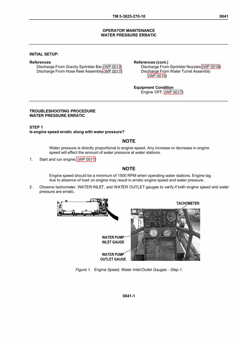
8/6/2019 TM 5-3825-270-10 ENGINEER MISSION MODULE WATER DISTRIBUTION
http://slidepdf.com/reader/full/tm-5-3825-270-10-engineer-mission-module-water-distribution 235/483
OPERATOR MAINTENANCEWATER PRESSURE ERRATIC
INITIAL SETUP:
ReferencesDischarge From Gravity Sprinkler Bar (WP 0013)Discharge From Hose Reel Assembly (WP 0017)
References (cont.)Discharge From Sprinkler Nozzles (WP 0016)Discharge From Water Turret Assembly
(WP 0015)
Equipment ConditionEngine OFF. (WP 0017)
TROUBLESHOOTING PROCEDUREWATER PRESSURE ERRATIC
STEP 1Is engine speed erratic along with water pressure?
NOTE
Water pressure is directly proportional to engine speed. Any increase or decrease in enginespeed will effect the amount of water pressure at water stations.
1. Start and run engine. (WP 0017)
NOTE
Engine speed should be a minimum of 1500 RPM when operating water stations. Engine lag
due to absence of load on engine may result in erratic engine speed and water pressure.2. Observe tachometer, WATER INLET, and WATER OUTLET gauges to verify if both engine speed and wate
pressure are erratic.
WATER PUMP
INLET GAUGE
WATER PUMP
OUTLET GAUGE
TACHOMETER
Figure 1. Engine Speed, Water Inlet/Outlet Gauges - Step 1.
TM 5-3825-270-10 0041
0041-1

8/6/2019 TM 5-3825-270-10 ENGINEER MISSION MODULE WATER DISTRIBUTION
http://slidepdf.com/reader/full/tm-5-3825-270-10-engineer-mission-module-water-distribution 236/483
CONDITION/INDICATIONIs engine speed erratic along with water pressure?
DECISIONNo - Go to step 2. (Step 2 - Are all applicable valves open or closed completely?)Yes - Notify maintenance personnel engine speed is erratic or surges.
STEP 2Are all applicable valves open or closed completely?
Verify all applicable valves for particular water station being used are closed or open completely:• Gravity sprinkler bar (WP 0013)• Water turret assembly (WP 0015)• Sprinkler Nozzles (WP 0016)• Hose reel assembly (WP 0017)
CONDITION/INDICATIONAre all applicable valves open or closed completely?
DECISIONNo - Close and/or open all applicable valves completely. Verify problem is solved. (Step 3 - Is water pressureerratic?)Yes - Problem not found. Notify maintenance personnel water pressure is erratic.
STEP 3Is water pressure erratic?
Operate water distributor while observing water pressure. (WP 0017)
CONDITION/INDICATIONIs water pressure erratic?
DECISIONNo - Problem is solved.Yes - Problem not found. Notify maintenance personnel engine overheats.
END OF WORK PACKAGE
TM 5-3825-270-10 0041
0041-2

8/6/2019 TM 5-3825-270-10 ENGINEER MISSION MODULE WATER DISTRIBUTION
http://slidepdf.com/reader/full/tm-5-3825-270-10-engineer-mission-module-water-distribution 237/483
OPERATOR MAINTENANCEEXCESSIVE PUMP NOISE
INITIAL SETUP:
ReferencesGeneral Information (WP 0001)Discharge From Hose Reel Assembly (WP 0017)
Equipment ConditionEngine OFF. (WP 0017)
TROUBLESHOOTING PROCEDUREEXCESSIVE PUMP NOISE
STEP 1Is water distributor operated within proper operator guidelines?
NOTE• The water pump is mechanically linked to the engine. Engine overspeed or excessive
rpm may cause water pump to operate at high revolutions causing excessive noise.
• When water level falls to 300 gallons (1,136 liters) or less, excessive water pump noisemay occur.
1. Start engine. (WP 0017)
CAUTION
Ensure not to operate water pump when water level falls below 300 gallons (1,136 liters).Water pump cavitation may occur. Failure to do so may result in damage to equipment.
2. Refer to operator instructions and control panel spray placard to ensure proper operating procedures areadhered to.
3. It may be necessary to partially open valve V5 to relieve pressure in water pump housing and allow fluid tocirculate through water tank to lower pump noise.
TM 5-3825-270-10 0042
0042-1

8/6/2019 TM 5-3825-270-10 ENGINEER MISSION MODULE WATER DISTRIBUTION
http://slidepdf.com/reader/full/tm-5-3825-270-10-engineer-mission-module-water-distribution 238/483
VALVE
V5
Figure 1. Valve V5 - Step 1.
CONDITION/INDICATIONIs water distributor operated within proper operator guidelines?
DECISIONNo - Operate water distributor within proper guidelines and tolerances. (WP 0017) Verify problem is solved.(Step 2 - Does water pump exhibit excessive noise?)Yes - Notify maintenance personnel water pump exhibits excessive noise.
STEP 2Does water pump exhibit excessive noise?
Operate water distributor while observing water pump noise. (WP 0017)
CONDITION/INDICATIONDoes water pump exhibit excessive noise?
DECISION
No - Problem is solved.Yes - Problem not found. Notify maintenance personnel water pump exhibits excessive noise.
END OF WORK PACKAGE
TM 5-3825-270-10 0042
0042-2

8/6/2019 TM 5-3825-270-10 ENGINEER MISSION MODULE WATER DISTRIBUTION
http://slidepdf.com/reader/full/tm-5-3825-270-10-engineer-mission-module-water-distribution 239/483
FIELD MAINTENANCEWORK LIGHTS DO NOT OPERATE
INITIAL SETUP:
ReferencesOperating Lights (WP 0006)Discharge From Hose Reel Assembly (WP 0017)
Equipment ConditionEngine OFF. (WP 0017)
TROUBLESHOOTING PROCEDUREWORK LIGHTS DO NOT OPERATE
STEP 1Are one or both work lights not working?
Operate work lights to determine if one or both are not working. (WP 0006)
CONDITION/INDICATIONAre one or both work lights not working?
DECISIONBoth work lights out - Go to step 2. (Step 2 - Is EMERGENCY STOP switch is in the on position?)One work light out - Notify maintenance personnel left or right work light is inoperative.
STEP 2Is EMERGENCY STOP switch is in the on position?
NOTE
Water distributor work lights will not illuminate if EMERGENCY STOP switch is in the off position.
Verify if EMERGENCY STOP switch is rotated out to on position.
EMERGENCY STOP SWITCH
Figure 1. Emergency Stop Switch - Step 2.
CONDITION/INDICATIONIs EMERGENCY STOP switch is in the on position?
TM 5-3825-270-10 0043
0043-1

8/6/2019 TM 5-3825-270-10 ENGINEER MISSION MODULE WATER DISTRIBUTION
http://slidepdf.com/reader/full/tm-5-3825-270-10-engineer-mission-module-water-distribution 240/483
DECISIONNo - Rotate EMERGENCY STOP switch to on position. Verify problem is solved. (Step 3 - Do work lightsilluminate?)Yes - Problem not found. Notify maintenance personnel work lights do not illuminate.
STEP 3Do work lights illuminate?
Attempt to operate work lights. (WP 0006)
CONDITION/INDICATIONDo work lights illuminate?
DECISIONNo - Problem not found. Notify maintenance personnel worklights do not illuminate.Yes - Problem is solved.
END OF WORK PACKAGE
TM 5-3825-270-10 0043
0043-2

8/6/2019 TM 5-3825-270-10 ENGINEER MISSION MODULE WATER DISTRIBUTION
http://slidepdf.com/reader/full/tm-5-3825-270-10-engineer-mission-module-water-distribution 241/483
OPERATOR MAINTENANCEWATER DISTRIBUTOR DOES NOT OPERATE REMOTELY
INITIAL SETUP:
ReferencesPLS Operator Manual (TM 9-2320-364-10)
References (cont.)Discharge From Sprinkler Nozzles (WP 0016)Universal Power Interface Kit (UPIK) Hookup
(WP 0012)
Equipment ConditionEngine OFF. (WP 0016)
TROUBLESHOOTING PROCEDUREWATER DISTRIBUTOR DOES NOT OPERATE REMOTELY
STEP 1Does ENGINE OFF/BATTERY DRAIN indicator illuminate at main control panel on rear of water distributor1. Ensure EMERGENCY STOP switch is in on position.
EMERGENCY STOP SWITCH
Figure 1. Emergency Stop Switch - Step 1.
2. Verify if ENGINE OFF/BATTERY DRAIN indicator is illuminated.
TM 5-3825-270-10 0044
0044-1

8/6/2019 TM 5-3825-270-10 ENGINEER MISSION MODULE WATER DISTRIBUTION
http://slidepdf.com/reader/full/tm-5-3825-270-10-engineer-mission-module-water-distribution 242/483
ENGINE OFF / BATTERY
DRAIN INDICATOR
Figure 2. Engine Off/Battery Drain Indicator - Step 1.
CONDITION/INDICATIONDoes ENGINE OFF/BATTERY DRAIN indicator illuminate at main control panel on rear of water distributor?
DECISIONNo - Go to step 2. (Step 2 - Is 15-amp circuit breaker tripped?)Yes - Ensure water distributor cab control box and harness are properly connected to prime mover universalpower interface kit (UPIK). (WP 0012) Verify problem is solved. (Step 3 - Does water distributor operateremotely?)
STEP 2Is 15-amp circuit breaker tripped?
NOTE
The 15-amp circuit breaker works in conjunction with the emergency stop switch to controlpower to the control panel. If a power surge is detected, the 15-amp circuit breaker will trip
prohibiting the emergency stop switch to supply power to the control panel and engine.Verify 15-amp circuit breaker position.
15-AMP
CIRCUIT
BREAKER
Figure 3. 15-Amp Circuit Breaker - Step 2.
CONDITION/INDICATIONIs 15-amp circuit breaker tripped?
TM 5-3825-270-10 0044
0044-2
8/6/2019 TM 5-3825-270-10 ENGINEER MISSION MODULE WATER DISTRIBUTION
http://slidepdf.com/reader/full/tm-5-3825-270-10-engineer-mission-module-water-distribution 243/483
DECISIONNo - Go to No Power to Control Panel. (WP 0045)Yes - Reset 15-amp circuit breaker. Verify problem is solved. (Step 3 - Does water distributor operateremotely?) If 15 amp circuit breaker trips again after reset, do not attempt to reset. Notify maintenance person15-amp circuit breaker is tripped.
STEP 3Does water distributor operate remotely?
Attempt to operate water distributor using cab control box. (WP 0016)
CONDITION/INDICATIONDoes water distributor operate remotely?
DECISIONNo - Problem not found. Notify maintenance personnel water distributor does not operate remotely.Yes - Problem is solved.
END OF WORK PACKAGE
TM 5-3825-270-10 0044
0044-3/4 blank

8/6/2019 TM 5-3825-270-10 ENGINEER MISSION MODULE WATER DISTRIBUTION
http://slidepdf.com/reader/full/tm-5-3825-270-10-engineer-mission-module-water-distribution 244/483
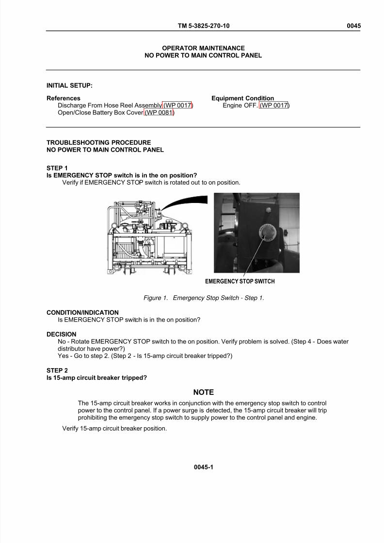
8/6/2019 TM 5-3825-270-10 ENGINEER MISSION MODULE WATER DISTRIBUTION
http://slidepdf.com/reader/full/tm-5-3825-270-10-engineer-mission-module-water-distribution 245/483
OPERATOR MAINTENANCENO POWER TO MAIN CONTROL PANEL
INITIAL SETUP:
ReferencesDischarge From Hose Reel Assembly (WP 0017)Open/Close Battery Box Cover (WP 0081)
Equipment ConditionEngine OFF. (WP 0017)
TROUBLESHOOTING PROCEDURENO POWER TO MAIN CONTROL PANEL
STEP 1Is EMERGENCY STOP switch is in the on position?
Verify if EMERGENCY STOP switch is rotated out to on position.
EMERGENCY STOP SWITCH
Figure 1. Emergency Stop Switch - Step 1.
CONDITION/INDICATIONIs EMERGENCY STOP switch is in the on position?
DECISIONNo - Rotate EMERGENCY STOP switch to the on position. Verify problem is solved. (Step 4 - Does water distributor have power?)Yes - Go to step 2. (Step 2 - Is 15-amp circuit breaker tripped?)
STEP 2
Is 15-amp circuit breaker tripped?
NOTE
The 15-amp circuit breaker works in conjunction with the emergency stop switch to controlpower to the control panel. If a power surge is detected, the 15-amp circuit breaker will tripprohibiting the emergency stop switch to supply power to the control panel and engine.
Verify 15-amp circuit breaker position.
TM 5-3825-270-10 0045
0045-1
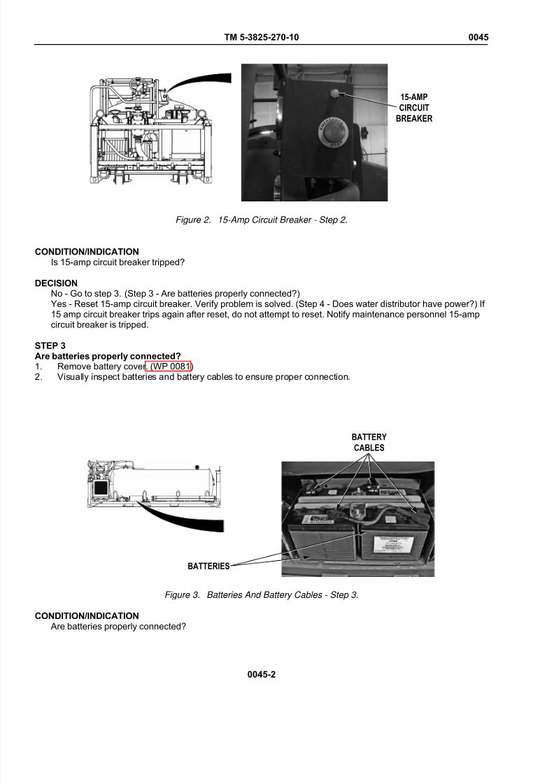
8/6/2019 TM 5-3825-270-10 ENGINEER MISSION MODULE WATER DISTRIBUTION
http://slidepdf.com/reader/full/tm-5-3825-270-10-engineer-mission-module-water-distribution 246/483
15-AMP
CIRCUIT
BREAKER
Figure 2. 15-Amp Circuit Breaker - Step 2.
CONDITION/INDICATIONIs 15-amp circuit breaker tripped?
DECISIONNo - Go to step 3. (Step 3 - Are batteries properly connected?)Yes - Reset 15-amp circuit breaker. Verify problem is solved. (Step 4 - Does water distributor have power?) If 15 amp circuit breaker trips again after reset, do not attempt to reset. Notify maintenance personnel 15-ampcircuit breaker is tripped.
STEP 3Are batteries properly connected?1. Remove battery cover . (WP 0081)2. Visually inspect batteries and battery cables to ensure proper connection.
BATTERY
CABLES
BATTERIES
Figure 3. Batteries And Battery Cables - Step 3.
CONDITION/INDICATIONAre batteries properly connected?
TM 5-3825-270-10 0045
0045-2

8/6/2019 TM 5-3825-270-10 ENGINEER MISSION MODULE WATER DISTRIBUTION
http://slidepdf.com/reader/full/tm-5-3825-270-10-engineer-mission-module-water-distribution 247/483
DECISIONNo - Notify maintenance personnel battery cables are not properly connected.Yes - Notify maintenance personnel water distributor does not have power.
STEP 4Does water distributor have power?1. If opened, close battery cover. (WP 0081)2. Ensure EMERGENCY STOP switch is in the on position.
EMERGENCY STOP SWITCH
Figure 4. Emergency Stop Switch - Step 4.
3. Verify if ENGINE OFF/BATTERY DRAIN indicator is illuminated.
ENGINE OFF / BATTERY
DRAIN INDICATOR
Figure 5. Engine Off/Battery Drain Indicator - Step 4.
CONDITION/INDICATIONDoes water distributor have power?
DECISIONNo - Notify maintenance personnel water distributor does not have power.Yes - Problem is solved.
END OF WORK PACKAGE
TM 5-3825-270-10 0045
0045-3/4 blank

8/6/2019 TM 5-3825-270-10 ENGINEER MISSION MODULE WATER DISTRIBUTION
http://slidepdf.com/reader/full/tm-5-3825-270-10-engineer-mission-module-water-distribution 248/483

8/6/2019 TM 5-3825-270-10 ENGINEER MISSION MODULE WATER DISTRIBUTION
http://slidepdf.com/reader/full/tm-5-3825-270-10-engineer-mission-module-water-distribution 249/483
OPERATOR MAINTENANCEBATTERY VOLTAGE GAUGE INOPERATIVE
INITIAL SETUP:
ReferencesNo Power To Control Panel (WP 0045)Discharge From Hose Reel Assembly (WP 0017)
Equipment ConditionEngine OFF. (WP 0017)
TROUBLESHOOTING PROCEDUREBATTERY VOLTAGE GAUGE INOPERATIVE
STEP 1Is ENGINE OFF/BATTERY DRAIN indicator illuminated?1. Verify if EMERGENCY STOP switch is rotated out to on position.
EMERGENCY STOP SWITCH
Figure 1. Emergency Stop Switch - Step 1.
2. Verify if ENGINE OFF/BATTERY DRAIN indicator illuminates.
ENGINE OFF / BATTERY
DRAIN INDICATOR
Figure 2. Engine Off/Battery Drain Indicator - Step 1.
TM 5-3825-270-10 0046
0046-1

8/6/2019 TM 5-3825-270-10 ENGINEER MISSION MODULE WATER DISTRIBUTION
http://slidepdf.com/reader/full/tm-5-3825-270-10-engineer-mission-module-water-distribution 250/483
CONDITION/INDICATIONIs ENGINE OFF/BATTERY DRAIN indicator illuminated?
DECISIONNo - Go to No Power To Control Panel. (WP 0045)Yes - Notify maintenance personnel battery voltage gauge inoperative.
END OF WORK PACKAGE
TM 5-3825-270-10 0046
0046-2
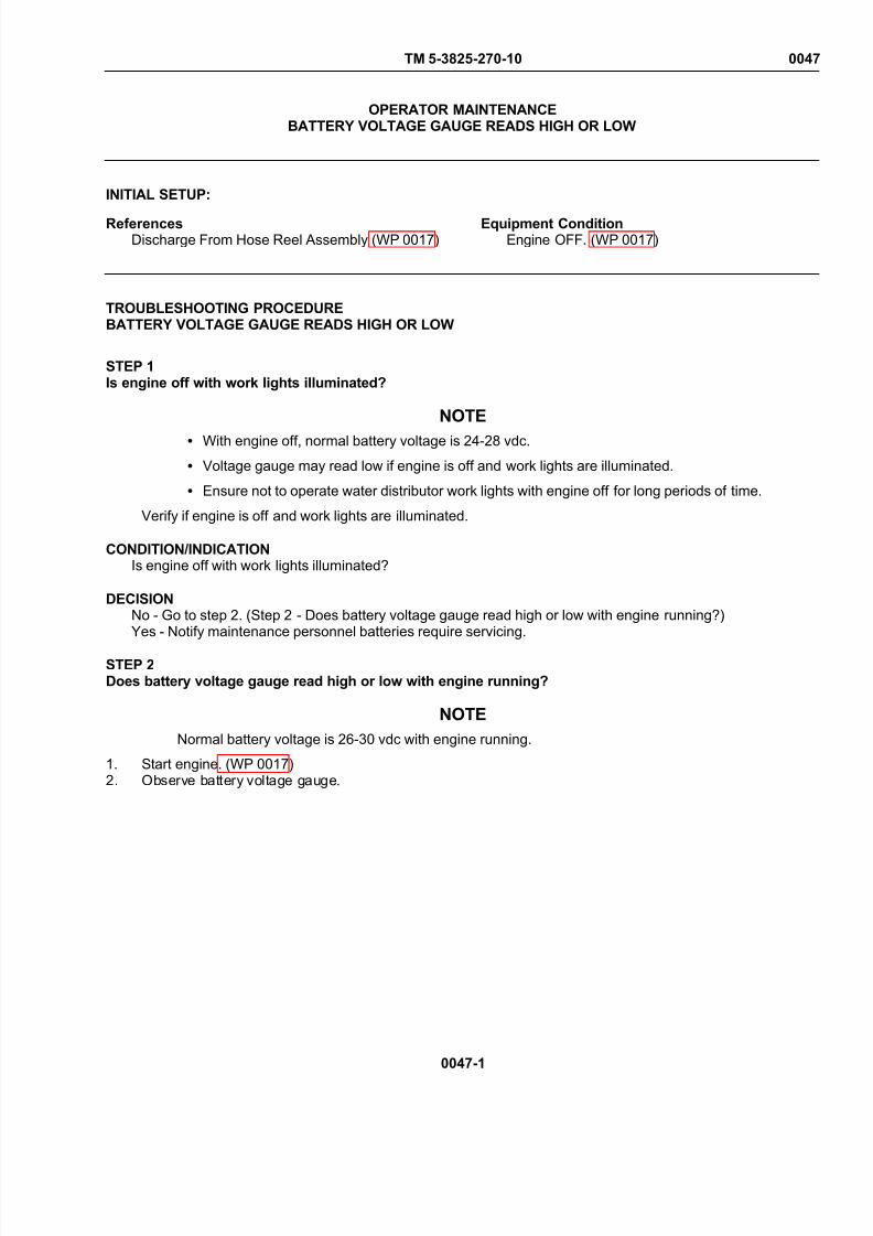
8/6/2019 TM 5-3825-270-10 ENGINEER MISSION MODULE WATER DISTRIBUTION
http://slidepdf.com/reader/full/tm-5-3825-270-10-engineer-mission-module-water-distribution 251/483
OPERATOR MAINTENANCEBATTERY VOLTAGE GAUGE READS HIGH OR LOW
INITIAL SETUP:
ReferencesDischarge From Hose Reel Assembly (WP 0017)
Equipment ConditionEngine OFF. (WP 0017)
TROUBLESHOOTING PROCEDUREBATTERY VOLTAGE GAUGE READS HIGH OR LOW
STEP 1Is engine off with work lights illuminated?
NOTE
• With engine off, normal battery voltage is 24-28 vdc.
• Voltage gauge may read low if engine is off and work lights are illuminated.
• Ensure not to operate water distributor work lights with engine off for long periods of time.
Verify if engine is off and work lights are illuminated.
CONDITION/INDICATIONIs engine off with work lights illuminated?
DECISIONNo - Go to step 2. (Step 2 - Does battery voltage gauge read high or low with engine running?)Yes - Notify maintenance personnel batteries require servicing.
STEP 2Does battery voltage gauge read high or low with engine running?
NOTE
Normal battery voltage is 26-30 vdc with engine running.
1. Start engine. (WP 0017)2. Observe battery voltage gauge.
TM 5-3825-270-10 0047
0047-1

8/6/2019 TM 5-3825-270-10 ENGINEER MISSION MODULE WATER DISTRIBUTION
http://slidepdf.com/reader/full/tm-5-3825-270-10-engineer-mission-module-water-distribution 252/483
BATTERY
VOLTAGE GAUGE
Figure 1. Battery Voltage Gauge - Step 2.
CONDITION/INDICATIONDoes battery voltage gauge read high or low with engine running?
DECISIONNo - Problem not found. Notify maintenance personnel work lights do not illuminate.Yes - Notify maintenance personnel voltage gauge reads high or low.
END OF WORK PACKAGE
TM 5-3825-270-10 0047
0047-2

8/6/2019 TM 5-3825-270-10 ENGINEER MISSION MODULE WATER DISTRIBUTION
http://slidepdf.com/reader/full/tm-5-3825-270-10-engineer-mission-module-water-distribution 253/483
OPERATOR MAINTENANCEMAIN CONTROL PANEL ENGINE OFF/BATTERY DRAIN INDICATOR DOES NOT ILLUMINATE
INITIAL SETUP:
ReferencesDischarge From Hose Reel Assembly (WP 0017)No Power To Control Panel (WP 0045)
Equipment ConditionEngine OFF. (WP 0017)
TROUBLESHOOTING PROCEDUREMAIN CONTROL PANEL ENGINE OFF/BATTERY DRAIN INDICATOR DOES NOT ILLUMINATE
STEP 1Does BATTERY VOLTMETER gauge read 24 to 28 VDC with ENGINE OFF/BATTERY DRAIN indicator inoperative?
1. Rotate EMERGENCY STOP switch to on position.
EMERGENCY STOP SWITCH
Figure 1. Emergency Stop Switch - Step 1.
2. Visually inspect BATTERY VOLTMETER gauge.
BATTERY
VOLTAGE GAUGE
Figure 2. Battery Voltmeter Gauge - Step 1.
TM 5-3825-270-10 0048
0048-1

8/6/2019 TM 5-3825-270-10 ENGINEER MISSION MODULE WATER DISTRIBUTION
http://slidepdf.com/reader/full/tm-5-3825-270-10-engineer-mission-module-water-distribution 254/483
CONDITION/INDICATIONDoes BATTERY VOLTMETER gauge read 24 to 28 VDC with ENGINE OFF/BATTERY DRAIN indicator inoperative?
DECISIONNo - Go to step 2. (Step 2 - Is 15-amp circuit breaker tripped?)Yes - Notify maintenance personnel main control panel ENGINE OFF/BATTERY DRAIN indicator isinoperative.
STEP 2Is 15-amp circuit breaker tripped?
NOTE
The 15-amp circuit breaker works in conjunction with the emergency stop switch to controlpower to the control panel. If a power surge is detected, the 15-amp circuit breaker will tripprohibiting the emergency stop switch to supply power to the control panel and engine.
Verify 15-amp circuit breaker position.
15-AMP
CIRCUIT
BREAKER
Figure 3. 15-Amp Circuit Breaker - Step 2.
CONDITION/INDICATIONIs 15-amp circuit breaker tripped?
DECISIONNo - Go to No Power To Control Panel. (WP 0045)Yes - Reset 15-amp circuit breaker. Verify problem is solved. (Step 3 - Does ENGINE OFF/BATTERY DRAINindictor illuminate?) If 15 amp circuit breaker trips again after reset, do not attempt to reset. Notify maintenancepersonnel 15-amp circuit breaker is tripped.
STEP 3Does ENGINE OFF/BATTERY DRAIN indictor illuminate?1. Rotate EMERGENCY STOP switch to on position.
TM 5-3825-270-10 0048
0048-2

8/6/2019 TM 5-3825-270-10 ENGINEER MISSION MODULE WATER DISTRIBUTION
http://slidepdf.com/reader/full/tm-5-3825-270-10-engineer-mission-module-water-distribution 255/483
EMERGENCY STOP SWITCH
Figure 4. Emergency Stop Switch - Step 3.
2. Verify if ENGINE OFF/BATTERY DRAIN indicator is illuminated.
ENGINE OFF / BATTERY
DRAIN INDICATOR
Figure 5. Engine Off/Battery Drain Indicator - Step 3.
CONDITION/INDICATIONDoes ENGINE OFF/BATTERY DRAIN indictor illuminate?
DECISIONNo - Notify maintenance personnel ENGINE OFF/BATTERY DRAIN indicator does not illuminate.Yes - Problem is solved.
END OF WORK PACKAGE
TM 5-3825-270-10 0048
0048-3/4 blank

8/6/2019 TM 5-3825-270-10 ENGINEER MISSION MODULE WATER DISTRIBUTION
http://slidepdf.com/reader/full/tm-5-3825-270-10-engineer-mission-module-water-distribution 256/483
8/6/2019 TM 5-3825-270-10 ENGINEER MISSION MODULE WATER DISTRIBUTION
http://slidepdf.com/reader/full/tm-5-3825-270-10-engineer-mission-module-water-distribution 257/483
OPERATOR MAINTENANCEENGINE OFF/BATTERY DRAIN INDICATOR STAYS ILLUMINATED WHEN STARTING
INITIAL SETUP:
ReferencesDischarge From Hose Reel Assembly (WP 0017)Engine Oil Pressure Gauge Reads Low
(WP 0050)Engine Overheats (WP 0036)
References (cont.)Engine Stalls (WP 0032)Excessive Water Pressure (WP 0039)
Equipment ConditionEngine OFF. (WP 0017)
TROUBLESHOOTING PROCEDUREENGINE OFF/BATTERY DRAIN INDICATOR STAYS ILLUMINATED WHEN STARTING
STEP 1Does engine start and shut down normally?
NOTE
If an engine fault is detected and engine is commanded to shut down, the engine off/drainlight will remain illuminated until fault is cleared and emergency stop switch is reset.
Verify operation is normal and engine does not shut down due to any of the following engine faults:(WP 0017)
• Air restriction (WP 0032)• Engine overheats (WP 0036)• Water pump outlet pressure exceeds 150 psi (WP 0039)• Engine oil pressure falls to 7 psi or less (WP 0050)
CONDITION/INDICATIONDoes engine start and shut down normally?
DECISIONNo - Notify maintenance personnel engine starts and/or shuts down abnormally.Yes - Notify maintenance personnel ENGINE OFF/BATTERY DRAIN light stays illuminated.
END OF WORK PACKAGE
TM 5-3825-270-10 0049
0049-1/2 blank

8/6/2019 TM 5-3825-270-10 ENGINEER MISSION MODULE WATER DISTRIBUTION
http://slidepdf.com/reader/full/tm-5-3825-270-10-engineer-mission-module-water-distribution 258/483

8/6/2019 TM 5-3825-270-10 ENGINEER MISSION MODULE WATER DISTRIBUTION
http://slidepdf.com/reader/full/tm-5-3825-270-10-engineer-mission-module-water-distribution 259/483
OPERATOR MAINTENANCEENGINE OIL PRESSURE GAUGE READS LOW
INITIAL SETUP:
ReferencesDischarge From Hose Reel Assembly (WP 0017)Operator Preventive Maintenance Checks And
Services (PMCS) (WP 0071)
Equipment ConditionEngine OFF. (WP 0017)
TROUBLESHOOTING PROCEDUREENGINE OIL PRESSURE GAUGE READS LOW
NOTE
Normal engine oil pressure is 28 to 57 psi (193 to 393 kPa).
STEP 1Is proper engine oil level present for operation?
Check engine oil level. (WP 0071)
CONDITION/INDICATIONIs proper engine oil level present for operation?
DECISIONNo - Fill engine to proper level with engine oil. (WP 0071) Verify problem is solved. (Step 3 - Does engine oilpressure gauge read low?)Yes - Go to step 2. (Step 2 - Is engine free from oil leaks?)
TM 5-3825-270-10 0050
0050-1

8/6/2019 TM 5-3825-270-10 ENGINEER MISSION MODULE WATER DISTRIBUTION
http://slidepdf.com/reader/full/tm-5-3825-270-10-engineer-mission-module-water-distribution 260/483
STEP 2Is engine free from oil leaks?
Visually inspect engine for oil leakage. (WP 0071)
CONDITION/INDICATION
Is engine free from oil leaks?
DECISIONNo - Notify maintenance personnel engine leaks oil.Yes - Notify maintenance personnel engine oil pressure gauge reads low.
STEP 3Does engine oil pressure gauge read low?1. Attempt to start engine. (WP 0017)2. If engine starts and continues to run, monitor engine oil pressure for a minimum of 1 minute.
CONDITION/INDICATIONDoes engine oil pressure gauge read low?
DECISIONNo - Problem is solved.Yes - Problem not found. Notify maintenance personnel engine oil pressure gauge reads low.
END OF WORK PACKAGE
TM 5-3825-270-10 0050
0050-2

8/6/2019 TM 5-3825-270-10 ENGINEER MISSION MODULE WATER DISTRIBUTION
http://slidepdf.com/reader/full/tm-5-3825-270-10-engineer-mission-module-water-distribution 261/483
OPERATOR MAINTENANCEENGINE OIL PRESSURE GAUGE READS HIGH
INITIAL SETUP:
ReferencesOperator Preventive Maintenance Checks And
Services (PMCS) (WP 0071)
Equipment ConditionEngine OFF.
TROUBLESHOOTING PROCEDUREENGINE OIL PRESSURE GAUGE READS HIGH
STEP 1Is engine oil pressure appropriate for desired engine speed?
NOTE• Normal engine oil pressure is 28 to 57 psi (193 to 393 kPa).
• If engine is cold, oil pressure may read slightly higher than normal until engine reachesnormal operating temperature.
NOTE
Engine oil pressure will increase with engine rpm.
Verify if engine oil pressure is within normal range.
CONDITION/INDICATIONIs engine oil pressure appropriate for desired engine speed?
DECISIONNo - Go to step 2. (Step 2 - Is engine oil level correct for operation?)Yes - Problem solved.
TM 5-3825-270-10 0051
0051-1

8/6/2019 TM 5-3825-270-10 ENGINEER MISSION MODULE WATER DISTRIBUTION
http://slidepdf.com/reader/full/tm-5-3825-270-10-engineer-mission-module-water-distribution 262/483
STEP 2Is engine oil level correct for operation?
Check engine oil level. (WP 0071)
CONDITION/INDICATION
Is engine oil level correct for operation?
DECISIONNo - Notify maintenance personnel engine requires oil to be drained to appropriate level.Yes - Notify maintenance personnel engine oil pressure gauge reads high.
END OF WORK PACKAGE
TM 5-3825-270-10 0051
0051-2

8/6/2019 TM 5-3825-270-10 ENGINEER MISSION MODULE WATER DISTRIBUTION
http://slidepdf.com/reader/full/tm-5-3825-270-10-engineer-mission-module-water-distribution 263/483
OPERATOR MAINTENANCEWATER PUMP INLET GAUGE INOPERATIVE
INITIAL SETUP:
ReferencesDischarge From Hose Reel Assembly (WP 0017)
Equipment ConditionEngine OFF. (WP 0017)
TROUBLESHOOTING PROCEDUREWATER PUMP INLET GAUGE INOPERATIVE
STEP 1Is valve V1 open and all other valves in correct position for operation?
NOTE
Valve V1 should be open for most discharge operations. Valve V1 does not need to be opento discharge from sprinkler bar.
Verify valve V1 position.
VALVE
V1
Figure 1. Valve V1 - Step 1.
CONDITION/INDICATIONIs valve V1 open and all other valves in correct position for operation?
DECISIONNo - Open valve V1. (WP 0017) Verify problem is solved. (Step 2 - Does water pump inlet gauge operate?)Yes - Notify maintenance personnel water pump inlet gauge inoperative.
STEP 2Does water pump inlet gauge operate?1. Start engine. (WP 0017)2. Operate water distributor while observing water pump inlet gauge. (WP 0017)
TM 5-3825-270-10 0052
0052-1
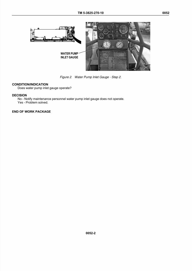
8/6/2019 TM 5-3825-270-10 ENGINEER MISSION MODULE WATER DISTRIBUTION
http://slidepdf.com/reader/full/tm-5-3825-270-10-engineer-mission-module-water-distribution 264/483
WATER PUMP
INLET GAUGE
Figure 2. Water Pump Inlet Gauge - Step 2.
CONDITION/INDICATIONDoes water pump inlet gauge operate?
DECISIONNo - Notify maintenance personnel water pump inlet gauge does not operate.Yes - Problem solved.
END OF WORK PACKAGE
TM 5-3825-270-10 0052
0052-2

8/6/2019 TM 5-3825-270-10 ENGINEER MISSION MODULE WATER DISTRIBUTION
http://slidepdf.com/reader/full/tm-5-3825-270-10-engineer-mission-module-water-distribution 265/483
OPERATOR MAINTENANCEWATER LEVEL HIGH INDICATOR DOES NOT ILLUMINATE
INITIAL SETUP:
ReferencesDischarge From Hose Reel Assembly (WP 0017)Load Tank At Strainer With System Pump And 3"
Hose (WP 0020)
Equipment ConditionEngine OFF. (WP 0017)
TROUBLESHOOTING PROCEDUREWATER LEVEL HIGH INDICATOR DOES NOT ILLUMINATE
NOTE
Water level high indicator will illuminate when water distributor tank is filled with 3,000 gallons(11,355 liters) of water.
STEP 1Is water distributor tank filled with 3,000 gallons (11,355 liters) of water?
Visually inspect water level indicator on front of water distributor tank.
WATER LEVEL
INDICATOR
Figure 1. Water Level Indicator - Step 1.
CONDITION/INDICATIONIs water distributor tank filled with 3,000 gallons (11,355 liters) of water?
DECISIONNo - Fill water distributor until water level indicator reads 3,000 gallons (11,355 liters). (WP 0020) Verify problem
is solved. (Step 2 - Does WATER LEVEL HIGH indicator illuminate?)Yes - Notify maintenance personnel WATER LEVEL HIGH indicator does not illuminate.
STEP 2Does WATER LEVEL HIGH indicator illuminate?1. Rotate EMERGENCY STOP switch to ON position.
TM 5-3825-270-10 0053
0053-1

8/6/2019 TM 5-3825-270-10 ENGINEER MISSION MODULE WATER DISTRIBUTION
http://slidepdf.com/reader/full/tm-5-3825-270-10-engineer-mission-module-water-distribution 266/483
EMERGENCY STOP SWITCH
Figure 2. Emergency Stop Switch - Step 2.
2. Observe WATER LEVEL HIGH indicator.
WATER LEVEL
HIGH INDICATOR
Figure 3. Water Level High indicator - Step 2.
CONDITION/INDICATIONDoes WATER LEVEL HIGH indicator illuminate?
DECISIONNo - Notify maintenance personnel WATER LEVEL HIGH indicator does not illuminate.Yes - Problem solved.
END OF WORK PACKAGE
TM 5-3825-270-10 0053
0053-2
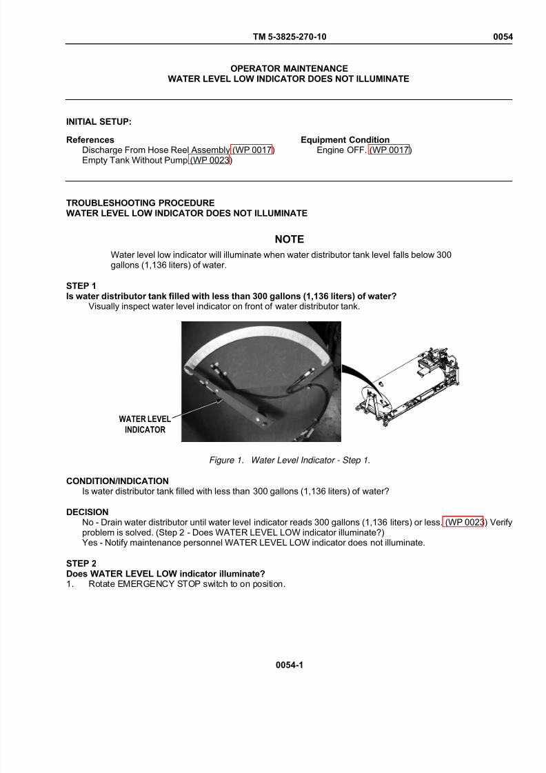
8/6/2019 TM 5-3825-270-10 ENGINEER MISSION MODULE WATER DISTRIBUTION
http://slidepdf.com/reader/full/tm-5-3825-270-10-engineer-mission-module-water-distribution 267/483
OPERATOR MAINTENANCEWATER LEVEL LOW INDICATOR DOES NOT ILLUMINATE
INITIAL SETUP:
ReferencesDischarge From Hose Reel Assembly (WP 0017)Empty Tank Without Pump (WP 0023)
Equipment ConditionEngine OFF. (WP 0017)
TROUBLESHOOTING PROCEDUREWATER LEVEL LOW INDICATOR DOES NOT ILLUMINATE
NOTE
Water level low indicator will illuminate when water distributor tank level falls below 300gallons (1,136 liters) of water.
STEP 1Is water distributor tank filled with less than 300 gallons (1,136 liters) of water?
Visually inspect water level indicator on front of water distributor tank.
WATER LEVEL
INDICATOR
Figure 1. Water Level Indicator - Step 1.
CONDITION/INDICATIONIs water distributor tank filled with less than 300 gallons (1,136 liters) of water?
DECISIONNo - Drain water distributor until water level indicator reads 300 gallons (1,136 liters) or less. (WP 0023) Verifyproblem is solved. (Step 2 - Does WATER LEVEL LOW indicator illuminate?)
Yes - Notify maintenance personnel WATER LEVEL LOW indicator does not illuminate.
STEP 2Does WATER LEVEL LOW indicator illuminate?1. Rotate EMERGENCY STOP switch to on position.
TM 5-3825-270-10 0054
0054-1

8/6/2019 TM 5-3825-270-10 ENGINEER MISSION MODULE WATER DISTRIBUTION
http://slidepdf.com/reader/full/tm-5-3825-270-10-engineer-mission-module-water-distribution 268/483
EMERGENCY STOP SWITCH
Figure 2. Emergency Stop Switch - Step 2.
2. Observe WATER LEVEL LOW indicator.
WATER LEVEL
LOW INDICATOR
Figure 3. Water Level Low Indicator - Step 2.
CONDITION/INDICATIONDoes WATER LEVEL LOW indicator illuminate?
DECISIONNo - Notify maintenance personnel WATER LEVEL LOW indicator does not illuminate.Yes - Problem solved.
END OF WORK PACKAGE
TM 5-3825-270-10 0054
0054-2

8/6/2019 TM 5-3825-270-10 ENGINEER MISSION MODULE WATER DISTRIBUTION
http://slidepdf.com/reader/full/tm-5-3825-270-10-engineer-mission-module-water-distribution 269/483
OPERATOR MAINTENANCEWATER LEVEL HIGH INDICATOR STAYS ILLUMINATED
INITIAL SETUP:
Equipment ConditionEngine OFF. (WP 0017)
TROUBLESHOOTING PROCEDUREWATER LEVEL HIGH INDICATOR STAYS ILLUMINATED
NOTE
Water level high indicator will illuminate when water distributor tank is filled with 3,000 gallons(11,355 liters) of water.
STEP 1Is water distributor tank filled with 3,000 gallons (11,355 liters) of water?
Visually inspect water level indicator on front of water distributor tank.
WATER LEVEL
INDICATOR
Figure 1. Water Level Indicator - Step 1.
CONDITION/INDICATIONIs water distributor tank filled with 3,000 gallons (11,355 liters) of water?
DECISIONNo - Notify maintenance personnel WATER LEVEL HIGH indicator stays illuminated.Yes - Problem solved.
END OF WORK PACKAGE
TM 5-3825-270-10 0055
0055-1/2 blank

8/6/2019 TM 5-3825-270-10 ENGINEER MISSION MODULE WATER DISTRIBUTION
http://slidepdf.com/reader/full/tm-5-3825-270-10-engineer-mission-module-water-distribution 270/483

8/6/2019 TM 5-3825-270-10 ENGINEER MISSION MODULE WATER DISTRIBUTION
http://slidepdf.com/reader/full/tm-5-3825-270-10-engineer-mission-module-water-distribution 271/483
OPERATOR MAINTENANCEWATER LEVEL LOW INDICATOR STAYS ILLUMINATED
INITIAL SETUP:
Equipment ConditionEngine OFF. (WP 0017)
TROUBLESHOOTING PROCEDUREWATER LEVEL LOW INDICATOR STAYS ILLUMINATED
NOTE
Water level low indicator will illuminate when water distributor tank level falls below 300gallons (1,136 liters) of water.
STEP 1Is water distributor tank filled with less than 300 gallons (1,136 liters) of water?
Visually inspect water level indicator on front of water distributor tank.
WATER LEVEL
INDICATOR
Figure 1. Water Level Indicator - Step 1.
CONDITION/INDICATIONIs water distributor tank filled with less than 300 gallons (1,136 liters) of water?
DECISIONNo - Notify maintenance personnel WATER LEVEL LOW indicator stays illuminated.Yes - Problem solved.
END OF WORK PACKAGE
TM 5-3825-270-10 0056
0056-1/2 blank

8/6/2019 TM 5-3825-270-10 ENGINEER MISSION MODULE WATER DISTRIBUTION
http://slidepdf.com/reader/full/tm-5-3825-270-10-engineer-mission-module-water-distribution 272/483

8/6/2019 TM 5-3825-270-10 ENGINEER MISSION MODULE WATER DISTRIBUTION
http://slidepdf.com/reader/full/tm-5-3825-270-10-engineer-mission-module-water-distribution 273/483
OPERATOR MAINTENANCEMANUAL WATER TURRET DOES NOT OPERATE
INITIAL SETUP:
Equipment ConditionEngine OFF. (WP 0015)Water Pump Primed. (WP 0019)
TROUBLESHOOTING PROCEDUREMANUAL WATER TURRET DOES NOT OPERATE
STEP 1Is valve V6 in open position?
Observe valve V6 position.
VALVE
V6
Figure 1. Valve V6 - Step 1.
CONDITION/INDICATIONIs valve V6 in open position?
DECISIONNo - Rotate valve V6 to open position. Verify problem is solved. (Step 3 - Does manual water turret operate?)Yes - Go to step 2. (Step 2 - Is valve V1 in open position?)
TM 5-3825-270-10 0057
0057-1

8/6/2019 TM 5-3825-270-10 ENGINEER MISSION MODULE WATER DISTRIBUTION
http://slidepdf.com/reader/full/tm-5-3825-270-10-engineer-mission-module-water-distribution 274/483
STEP 2Is valve V1 in open position?
Observe valve V1 position.
VALVE
V1
Figure 2. Valve V1 - Step 2.
CONDITION/INDICATIONIs valve V1 in open position?
DECISIONNo - Rotate valve V1 to open position. (WP 0015) Verify problem is solved. (Step 3 - Does manual water turretoperate?)Yes - Problem not found. Notify maintenance personnel manual water turret does not operate.
STEP 3Does manual water turret operate?
Attempt to operate manual water turret. (WP 0015)
CONDITION/INDICATIONDoes manual water turret operate?
DECISIONNo - Notify maintenance personnel manual water turret does not operate.Yes - Problem solved.
END OF WORK PACKAGE
TM 5-3825-270-10 0057
0057-2

8/6/2019 TM 5-3825-270-10 ENGINEER MISSION MODULE WATER DISTRIBUTION
http://slidepdf.com/reader/full/tm-5-3825-270-10-engineer-mission-module-water-distribution 275/483
OPERATOR MAINTENANCEMANUAL WATER TURRET OUTPUT LOW
INITIAL SETUP:
ReferencesGeneral Information (WP 0001)Equipment Description and Data (WP 0002)Circulate Tank With Pump To Blend Or Rinse
(WP 0018)
References (cont.)Discharge From Water Turret Assembly
(WP 0015)Prime Fully Drained Pump (WP 0019)
Equipment ConditionEngine ON. (WP 0015)Water pump primed. (WP 0019)
TROUBLESHOOTING PROCEDURE
MANUAL WATER TURRET OUTPUT LOW
STEP 1Is valve V6 completely open?
Verify valve V6 position.
VALVE
V6
Figure 1. Valve V6 - Step 1.
CONDITION/INDICATIONIs valve V6 completely open?
DECISIONNo - Fully open valve V6. (WP 0015) Verify problem is solved. (Step 5 - Does manual water turret operate at fupressure (no more than 20% below normal)? Refer to Equipment Description and Data (WP 0002) for normalpressure readings.)Yes - Go to step 2. (Step 2 - Is valve V1 completely open?)
STEP 2
TM 5-3825-270-10 0058
0058-1

8/6/2019 TM 5-3825-270-10 ENGINEER MISSION MODULE WATER DISTRIBUTION
http://slidepdf.com/reader/full/tm-5-3825-270-10-engineer-mission-module-water-distribution 276/483
Is valve V1 completely open?Verify valve V1 position.
VALVE
V1
Figure 2. Valve V1 - Step 2.
CONDITION/INDICATIONIs valve V1 completely open?
DECISIONNo - Fully open valve V1. (WP 0015) Verify problem is solved. (Step 5 - Does manual water turret operate at fullpressure (no more than 20% below normal)? Refer to Equipment Description and Data (WP 0002) for normalpressure readings.)Yes - Go to step 3. (Step 3 - Is valve V5 completely closed?)
STEP 3Is valve V5 completely closed?
Verify valve V5 position.
TM 5-3825-270-10 0058
0058-2

8/6/2019 TM 5-3825-270-10 ENGINEER MISSION MODULE WATER DISTRIBUTION
http://slidepdf.com/reader/full/tm-5-3825-270-10-engineer-mission-module-water-distribution 277/483
VALVE
V5
Figure 3. Valve V5 - Step 3.
CONDITION/INDICATIONIs valve V5 completely closed?
DECISIONNo - Fully close valve V5. (WP 0018) Verify problem is solved. (Step 5 - Does manual water turret operate atfull pressure (no more than 20% below normal)? Refer to Equipment Description and Data(WP 0002) for normapressure readings.)Yes - Go to step 4. (Step 4 - Is water pressure present low after ensuring proper operation of water distributor?)
STEP 4Is water pressure present low after ensuring proper operation of water distributor?
NOTE
Water pressure is directly proportional to engine speed. Any increase or decrease in engine
speed will effect the amount of water pressure at water stations.Ensure engine speed is appropriate for desired water distributor performance. (WP 0015)
CONDITION/INDICATIONIs water pressure present low after ensuring proper operation of water distributor?
DECISIONNo - Problem solved.Yes - Problem not found. Notify maintenance personnel manual water turret pressure is low.
TM 5-3825-270-10 0058
0058-3

8/6/2019 TM 5-3825-270-10 ENGINEER MISSION MODULE WATER DISTRIBUTION
http://slidepdf.com/reader/full/tm-5-3825-270-10-engineer-mission-module-water-distribution 278/483
STEP 5Does manual water turret operate at full pressure (no more than 20% below normal)? Refer to EquipmentDescription and Data (WP 0002) for normal pressure readings.
Operate manual water turret while observing water pressure. (WP 0015)
CONDITION/INDICATIONDoes manual water turret operate at full pressure (no more than 20% below normal)? Refer to EquipmentDescription and Data (WP 0002) for normal pressure readings.
DECISIONNo - Problem not found. Notify maintenance personnel manual water turret pressure is low.Yes - Problem solved.
END OF WORK PACKAGE
TM 5-3825-270-10 0058
0058-4

8/6/2019 TM 5-3825-270-10 ENGINEER MISSION MODULE WATER DISTRIBUTION
http://slidepdf.com/reader/full/tm-5-3825-270-10-engineer-mission-module-water-distribution 279/483
OPERATOR MAINTENANCEGRAVITY FED SPRINKLER BAR DOES NOT OPERATE
INITIAL SETUP:
ReferencesDischarge From Gravity Sprinkler Bar (WP 0013)Discharge From Water Turret Assembly
(WP 0015)
Equipment ConditionEngine OFF. (WP 0015)
TROUBLESHOOTING PROCEDUREGRAVITY FED SPRINKLER BAR DOES NOT OPERATE
STEP 1Is valve V8 in open position?
Verify valve V8 position.
VALVE V8
Figure 1. Valve V8 - Step 1.
CONDITION/INDICATIONIs valve V8 in open position?
DECISIONNo - Rotate valve V8 to open position. Verify problem is solved. (Step 2 - Does gravity fed sprinkler bar operate?)Yes - Notify maintenance personnel gravity fed sprinkler bar does not operate.
STEP 2Does gravity fed sprinkler bar operate?
Attempt to operate gravity fed sprinkler bar. (WP 0013)
CONDITION/INDICATIONDoes gravity fed sprinkler bar operate?
TM 5-3825-270-10 0059
0059-1

8/6/2019 TM 5-3825-270-10 ENGINEER MISSION MODULE WATER DISTRIBUTION
http://slidepdf.com/reader/full/tm-5-3825-270-10-engineer-mission-module-water-distribution 280/483
DECISIONNo - Notify maintenance personnel gravity fed sprinkler bar does not operate.Yes - Problem solved.
END OF WORK PACKAGE
TM 5-3825-270-10 0059
0059-2
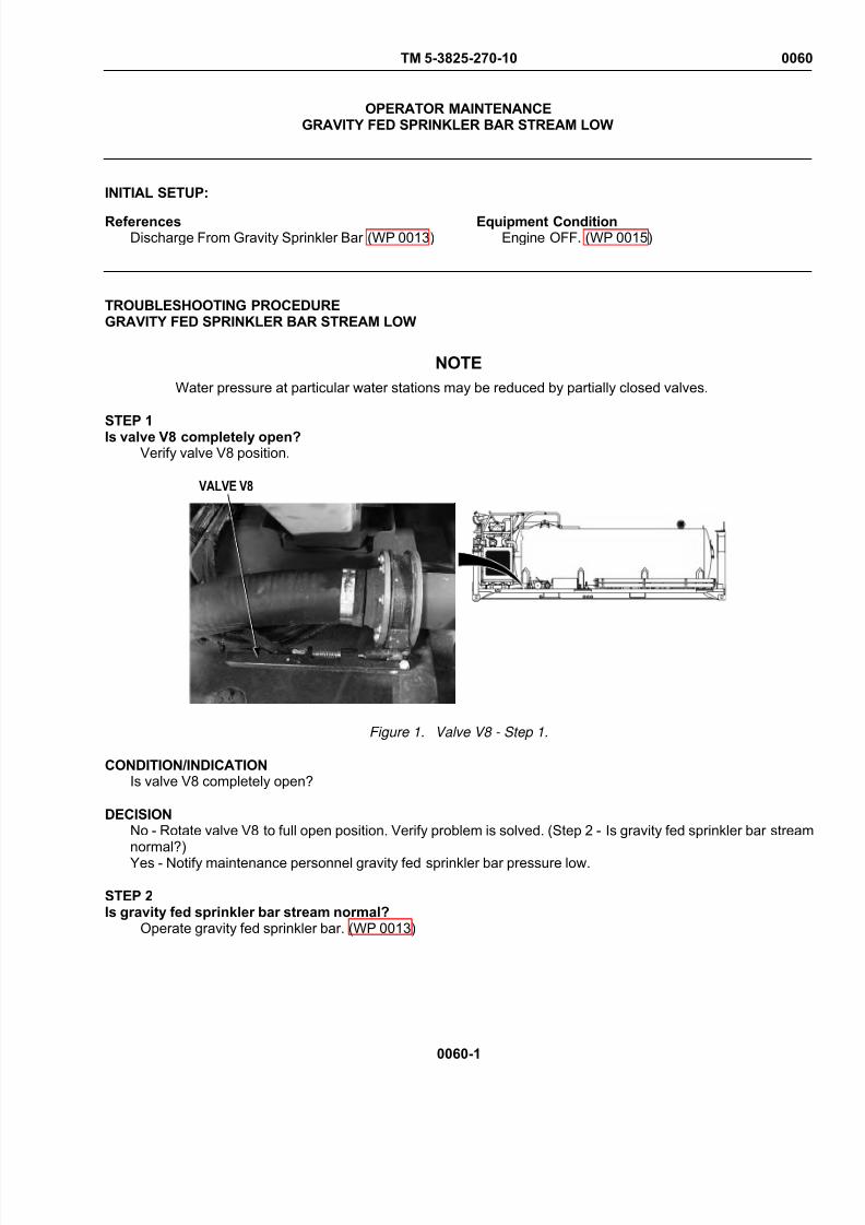
8/6/2019 TM 5-3825-270-10 ENGINEER MISSION MODULE WATER DISTRIBUTION
http://slidepdf.com/reader/full/tm-5-3825-270-10-engineer-mission-module-water-distribution 281/483
OPERATOR MAINTENANCEGRAVITY FED SPRINKLER BAR STREAM LOW
INITIAL SETUP:
ReferencesDischarge From Gravity Sprinkler Bar (WP 0013)
Equipment ConditionEngine OFF. (WP 0015)
TROUBLESHOOTING PROCEDUREGRAVITY FED SPRINKLER BAR STREAM LOW
NOTE
Water pressure at particular water stations may be reduced by partially closed valves.
STEP 1Is valve V8 completely open?
Verify valve V8 position.
VALVE V8
Figure 1. Valve V8 - Step 1.
CONDITION/INDICATIONIs valve V8 completely open?
DECISIONNo - Rotate valve V8 to full open position. Verify problem is solved. (Step 2 - Is gravity fed sprinkler bar streamnormal?)
Yes - Notify maintenance personnel gravity fed sprinkler bar pressure low.
STEP 2Is gravity fed sprinkler bar stream normal?
Operate gravity fed sprinkler bar. (WP 0013)
TM 5-3825-270-10 0060
0060-1
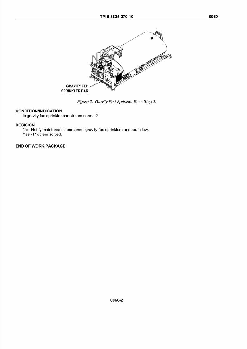
8/6/2019 TM 5-3825-270-10 ENGINEER MISSION MODULE WATER DISTRIBUTION
http://slidepdf.com/reader/full/tm-5-3825-270-10-engineer-mission-module-water-distribution 282/483
GRAVITY FED
SPRINKLER BAR
Figure 2. Gravity Fed Sprinkler Bar - Step 2.
CONDITION/INDICATIONIs gravity fed sprinkler bar stream normal?
DECISIONNo - Notify maintenance personnel gravity fed sprinkler bar stream low.Yes - Problem solved.
END OF WORK PACKAGE
TM 5-3825-270-10 0060
0060-2

8/6/2019 TM 5-3825-270-10 ENGINEER MISSION MODULE WATER DISTRIBUTION
http://slidepdf.com/reader/full/tm-5-3825-270-10-engineer-mission-module-water-distribution 283/483
OPERATOR MAINTENANCESPRINKLER HEADS DO NOT OPERATE
INITIAL SETUP:
ReferencesDischarge From Sprinkler Nozzles (WP 0016)Prime Fully Drained Pump (WP 0019)
References (cont.)PLS Prime Mover Operator Manual (TM
9-2320-364-10)Universal Power Interface Kit (UPIK) Hookup
(WP 0012)
Equipment ConditionEngine ON. (WP 0016)Water pump primed. (WP 0019)
TROUBLESHOOTING PROCEDURESPRINKLER HEADS DO NOT OPERATE
NOTE
• Operation of left and right sprinkler heads require connection to an air system supply andadequate pressure.
• Prime mover engine must be running to provide adequate air pressure to water distributor sprinkler heads.
• Minimum air pressure to operate sprinkler heads is 90 psi (620 kPa).
STEP 1
Are both sprinkler heads inoperative?1. Attempt to operate both sprinkler heads. (WP 0016)2. Verify if both sprinkler heads do not operate.
CONDITION/INDICATIONAre both sprinkler heads inoperative?
DECISIONNo - If only one sprinkler head is inoperative, notify maintenance personnel applicable sprinkler head isinoperative.Yes - Go to step 2. (Step 2 - Is water distributor properly connected to exterior air source?)
STEP 2
Is water distributor properly connected to exterior air source?Verify if water distributor is connected to exterior air source. (WP 0012)
CONDITION/INDICATIONIs water distributor properly connected to exterior air source?
DECISIONNo - Properly connect water distributor to prime mover . (WP 0012) Verify problem is solved. (Step 4 - Do sprinklheads operate?)Yes - Go to step 3. (Step 3 - Are proper sprinkler head operating procedures being used?)
TM 5-3825-270-10 0061
0061-1

8/6/2019 TM 5-3825-270-10 ENGINEER MISSION MODULE WATER DISTRIBUTION
http://slidepdf.com/reader/full/tm-5-3825-270-10-engineer-mission-module-water-distribution 284/483
STEP 3Are proper sprinkler head operating procedures being used?
Refer to Discharge From Sprinkler Nozzles (WP 0016) for proper sprinkler head operation.
CONDITION/INDICATIONAre proper sprinkler head operating procedures being used?
DECISIONNo - Follow sprinkler head operating procedures. (WP 0016) Verify problem is solved. (Step 4 - Do sprinkler heads operate?)Yes - Notify maintenance personnel sprinkler heads do not operate.
STEP 4Do sprinkler heads operate?
Attempt to operate sprinkler heads. (WP 0016)
CONDITION/INDICATIONDo sprinkler heads operate?
DECISIONNo - Notify maintenance personnel sprinkler heads do not operate.Yes - Problem solved.
END OF WORK PACKAGE
TM 5-3825-270-10 0061
0061-2

8/6/2019 TM 5-3825-270-10 ENGINEER MISSION MODULE WATER DISTRIBUTION
http://slidepdf.com/reader/full/tm-5-3825-270-10-engineer-mission-module-water-distribution 285/483
OPERATOR MAINTENANCESPRINKLER HEAD OUTPUT LOW
INITIAL SETUP:
ReferencesEquipment Description and Data (WP 0002)Discharge From Sprinkler Nozzles (WP 0016)Prime Fully Drained Pump (WP 0019)
References (cont.)PLS Prime Mover Operator Manual (TM
9-2320-364-10)Universal Power Interface Kit (UPIK) Hookup
(WP 0012)
Equipment ConditionEngine ON. (WP 0016)Water pump primed. (WP 0019)
TROUBLESHOOTING PROCEDURESPRINKLER HEAD OUTPUT LOW
NOTE
• Operation of left and right sprinkler heads require connection to an air system supply andadequate pressure.
• When valve V5 is open, water sprinkler nozzles will have less pressure.
STEP 1Is water distributor properly connected to prime mover?
Verify if water distributor is connected to prime mover.
CONDITION/INDICATIONIs water distributor properly connected to prime mover?
DECISIONNo - Properly connect water distributor to prime mover . (WP 0012) Verify problem is solved. (Step 5 - Do sprinklheads have appropriate pressure (no more than 20% below normal)? Refer to Equipment Description andData (WP 0002) for normal pressure readings.)Yes - Go to step 2. (Step 2 - Is air pressure adequate for operating sprinkler heads?)
STEP 2Is air pressure adequate for operating sprinkler heads?
Check prime mover air supply pressure. (TM 9-2320-364-10)
CONDITION/INDICATIONIs air pressure adequate for operating sprinkler heads?
DECISIONNo - Increase prime mover air supply pressure. (WP 0086) Verify problem is solved. (Step 5 - Do sprinkler headhave appropriate pressure (no more than 20% below normal)? Refer to Equipment Description and Data(WP 0002) for normal pressure readings.)Yes - Go to step 3. (Step 3 - Is valve V1 completely open?)
TM 5-3825-270-10 0062
0062-1

8/6/2019 TM 5-3825-270-10 ENGINEER MISSION MODULE WATER DISTRIBUTION
http://slidepdf.com/reader/full/tm-5-3825-270-10-engineer-mission-module-water-distribution 286/483
STEP 3Is valve V1 completely open?
Verify valve V1 position.
VALVE
V1
Figure 1. Valve V1 - Step 3.
CONDITION/INDICATIONIs valve V1 completely open?
DECISIONNo - Fully open valve V1. (WP 0015) Verify problem is solved. (Step 5 - Do sprinkler heads have appropriatepressure (no more than 20% below normal)? Refer to Equipment Description and Data (WP 0002) for normalpressure readings.)Yes - Go to step 4. (Step 4 - Is valve V5 completely closed?)
STEP 4Is valve V5 completely closed?
Verify valve V5 position.
TM 5-3825-270-10 0062
0062-2

8/6/2019 TM 5-3825-270-10 ENGINEER MISSION MODULE WATER DISTRIBUTION
http://slidepdf.com/reader/full/tm-5-3825-270-10-engineer-mission-module-water-distribution 287/483
VALVE
V5
Figure 2. Valve V5 - Step 4.
CONDITION/INDICATIONIs valve V5 completely closed?
DECISIONNo - Fully close valve V5. (WP 0018) Verify problem is solved. (Step 5 - Do sprinkler heads have appropriatepressure (no more than 20% below normal)? Refer to Equipment Description and Data (WP 0002) for normalpressure readings.)Yes - Notify maintenance personnel sprinkler heads have low pressure.
STEP 5Do sprinkler heads have appropriate pressure (no more than 20% below normal)? Refer to EquipmentDescription and Data (WP 0002) for normal pressure readings.
Operate sprinkler heads. (WP 0016)
CONDITION/INDICATIONDo sprinkler heads have appropriate pressure (no more than 20% below normal)? Refer to Equipment
Description and Data (WP 0002) for normal pressure readings.
DECISIONNo - Notify maintenance personnel sprinkler heads have low pressure.Yes - Problem solved.
END OF WORK PACKAGE
TM 5-3825-270-10 0062
0062-3/4 blank

8/6/2019 TM 5-3825-270-10 ENGINEER MISSION MODULE WATER DISTRIBUTION
http://slidepdf.com/reader/full/tm-5-3825-270-10-engineer-mission-module-water-distribution 288/483

8/6/2019 TM 5-3825-270-10 ENGINEER MISSION MODULE WATER DISTRIBUTION
http://slidepdf.com/reader/full/tm-5-3825-270-10-engineer-mission-module-water-distribution 289/483
OPERATOR MAINTENANCEWATER HOSE DOES NOT OPERATE
INITIAL SETUP:
ReferencesDischarge From Hose Reel Assembly (WP 0017)Prime Fully Drained Pump (WP 0019)Water Pump Does Not Operate (WP 0038)
Equipment ConditionEngine OFF. (WP 0017)Water pump primed. (WP 0019)
TROUBLESHOOTING PROCEDUREWATER HOSE DOES NOT OPERATE
STEP 1Is valve V1 and valve V7 in open position?
1. Observe valve V1 position.
VALVE
V1
Figure 1. Valve V1 - Step 1.
2. Observe valve V7 position.
TM 5-3825-270-10 0063
0063-1

8/6/2019 TM 5-3825-270-10 ENGINEER MISSION MODULE WATER DISTRIBUTION
http://slidepdf.com/reader/full/tm-5-3825-270-10-engineer-mission-module-water-distribution 290/483
VALVE V7
Figure 2. Valve V7 - Step 1.
CONDITION/INDICATIONIs valve V1 and valve V7 in open position?
DECISIONNo - Start engine and rotate valve V1 and valve V7 to open position.(WP 0017) Verify problem is solved. (Step4 - Does water hose operate?)Yes - Go to step 2. (Step 2 - Is water hose free of kinks and blockage?)
STEP 2Is water hose free of kinks and blockage?1. Completely unravel water hose from hose reel. (WP 0078)2. Visually inspect water hose for kinks and blockage.
WATER
HOSE
Figure 3. Water Hose - Step 2.
CONDITION/INDICATIONIs water hose free of kinks and blockage?
DECISIONNo - Remove kink and/or blockage if possible. Verify problem is solved. (Step 4 - Does water hose operate?) If blockage and/or kink in water hose cannot be removed, or water hose is damaged, notify maintenance personnelof water hose damage.Yes - Go to step 3. (Step 3 - Is WATER PUMP OUTLET pressure within normal operating range?)
TM 5-3825-270-10 0063
0063-2

8/6/2019 TM 5-3825-270-10 ENGINEER MISSION MODULE WATER DISTRIBUTION
http://slidepdf.com/reader/full/tm-5-3825-270-10-engineer-mission-module-water-distribution 291/483
STEP 3Is WATER PUMP OUTLET pressure within normal operating range?1. Start engine and set engine speed to 1500 rpm. (WP 0017)2. Observe WATER PUMP OUTLET gauge.
WATER PUMP
OUTLET GAUGE
Figure 4. Water Pump Outlet Gauge - Step 3.
NOTE
Normal water pump output pressure is approximately 50 psi (344 kPa) when operating water hose with engine speed set to 1500 rpm.
3. Note WATER PUMP OUTLET gauge reading.4. Shutdown engine. (WP 0017)
CONDITION/INDICATIONIs WATER PUMP OUTLET pressure within normal operating range?
DECISIONNo - Go to Water Pump Does Not Operate. (WP 0038)Yes - Problem not found. Notify maintenance personnel hose reel water hose does not operate.
STEP 4Does water hose operate?
Operate water hose. (WP 0017)
CONDITION/INDICATIONDoes water hose operate?
DECISIONNo - Problem not found. Notify maintenance personnel water hose does not operate.
Yes - Problem solved.
END OF WORK PACKAGE
TM 5-3825-270-10 0063
0063-3/4 blank

8/6/2019 TM 5-3825-270-10 ENGINEER MISSION MODULE WATER DISTRIBUTION
http://slidepdf.com/reader/full/tm-5-3825-270-10-engineer-mission-module-water-distribution 292/483

8/6/2019 TM 5-3825-270-10 ENGINEER MISSION MODULE WATER DISTRIBUTION
http://slidepdf.com/reader/full/tm-5-3825-270-10-engineer-mission-module-water-distribution 293/483
OPERATOR MAINTENANCEWATER HOSE OUTPUT LOW
INITIAL SETUP:
ReferencesEquipment Description and Data (WP 0002)Discharge From Hose Reel Assembly (WP 0017)Operator Preventive Maintenance Checks And
Service (WP 0071)Prime Fully Drained Pump (WP 0019)
References (cont.)Stow/Unstow Hoses (WP 0078)Water Pump Does Not Operate (WP 0038)
Equipment ConditionEngine OFF. (WP 0017)Water pump primed. (WP 0019)
TROUBLESHOOTING PROCEDUREWATER HOSE OUTPUT LOW
STEP 1Are valve V1 and valve V7 completely open?1. Observe valve V1 position.
VALVE
V1
Figure 1. Valve V1 - Step 1.
2. Observe valve V7 position.
TM 5-3825-270-10 0064
0064-1

8/6/2019 TM 5-3825-270-10 ENGINEER MISSION MODULE WATER DISTRIBUTION
http://slidepdf.com/reader/full/tm-5-3825-270-10-engineer-mission-module-water-distribution 294/483
VALVE V7
Figure 2. Valve V7 - Step 1.
CONDITION/INDICATIONAre valve V1 and valve V7 completely open?
DECISIONNo - Completely open valve V1 and valve V7. (WP 0017) Verify problem is solved. (Step 5 - Is water hosepressure normal (no more than 20% below normal)? Refer to Equipment Description and Data (WP 0002) for normal pressure readings.)Yes - Go to step 2. (Step 2 - Is valve V5 completely closed?)
STEP 2Is valve V5 completely closed?
Verify valve V5 position.
TM 5-3825-270-10 0064
0064-2
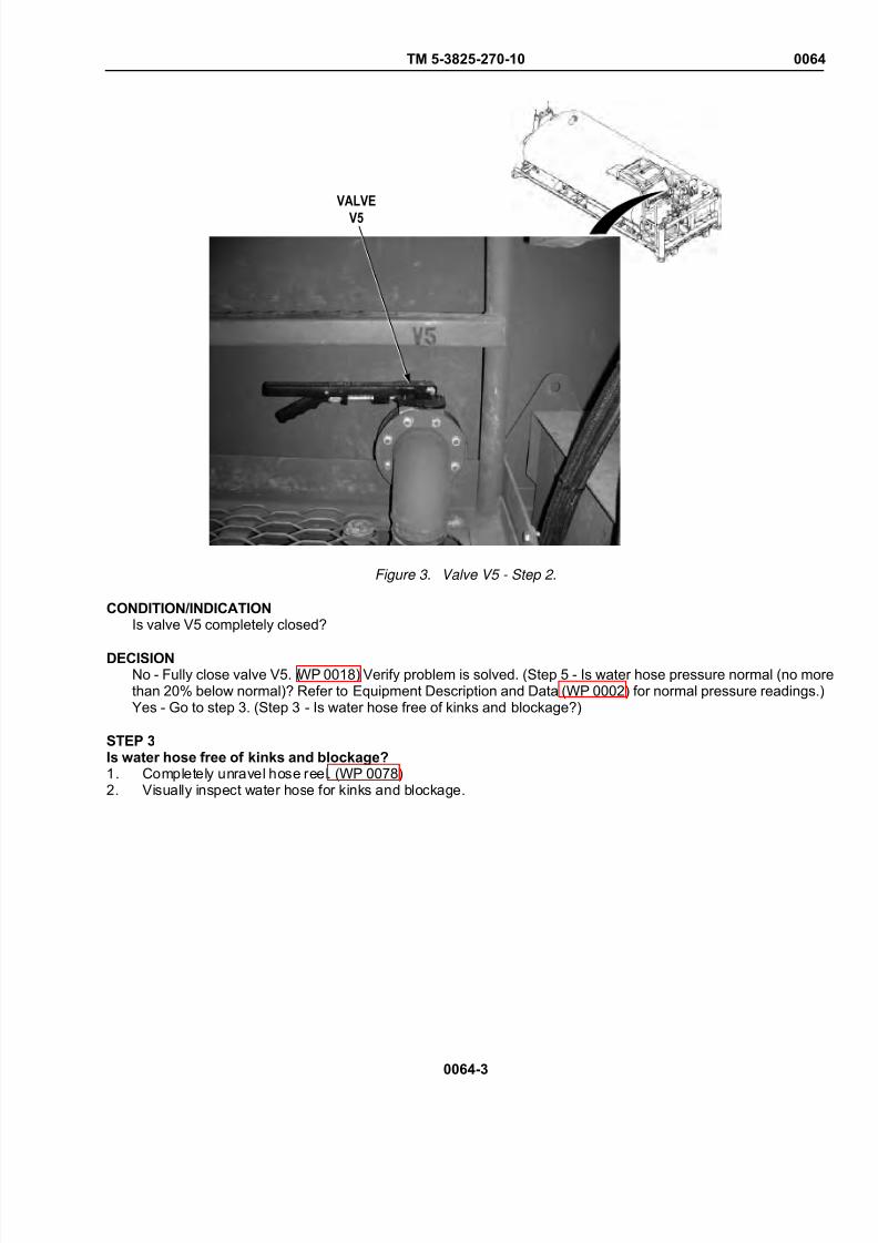
8/6/2019 TM 5-3825-270-10 ENGINEER MISSION MODULE WATER DISTRIBUTION
http://slidepdf.com/reader/full/tm-5-3825-270-10-engineer-mission-module-water-distribution 295/483
VALVE
V5
Figure 3. Valve V5 - Step 2.
CONDITION/INDICATIONIs valve V5 completely closed?
DECISIONNo - Fully close valve V5. (WP 0018) Verify problem is solved. (Step 5 - Is water hose pressure normal (no mothan 20% below normal)? Refer to Equipment Description and Data (WP 0002) for normal pressure readings.)Yes - Go to step 3. (Step 3 - Is water hose free of kinks and blockage?)
STEP 3Is water hose free of kinks and blockage?1. Completely unravel hose reel. (WP 0078)2. Visually inspect water hose for kinks and blockage.
TM 5-3825-270-10 0064
0064-3

8/6/2019 TM 5-3825-270-10 ENGINEER MISSION MODULE WATER DISTRIBUTION
http://slidepdf.com/reader/full/tm-5-3825-270-10-engineer-mission-module-water-distribution 296/483
WATER
HOSE
Figure 4. Water Hose - Step 3.
CONDITION/INDICATIONIs water hose free of kinks and blockage?
DECISIONNo - Remove kink and/or blockage if possible. (WP 0071) Verify problem is solved. (Step 5 - Is water hosepressure normal (no more than 20% below normal)? Refer to Equipment Description and Data (WP 0002) for normal pressure readings.) If blockage and/or kink in water hose cannot be removed, or water hose is damaged,notify maintenance personnel of water hose damage.Yes - Go to step 4. (Step 4 - Is WATER PUMP OUTLET pressure within normal operating range (no more than20% below normal)? Refer to Equipment Description and Data (WP 0002) for normal pressure readings.)
STEP 4Is WATER PUMP OUTLET pressure within normal operating range (no more than 20% below normal)? Refer to Equipment Description and Data (WP 0002) for normal pressure readings.1. Start engine and set engine speed to 1500 rpm. (WP 0017)2. Observe WATER PUMP OUTLET gauge.
WATER PUMP
OUTLET GAUGE
Figure 5. Water Pump Outlet Gauge - Step 4.
NOTE
Normal water pump output pressure is approximately 50 psi (344 kPa) when operating water hose with engine speed set to 1500 rpm.
TM 5-3825-270-10 0064
0064-4

8/6/2019 TM 5-3825-270-10 ENGINEER MISSION MODULE WATER DISTRIBUTION
http://slidepdf.com/reader/full/tm-5-3825-270-10-engineer-mission-module-water-distribution 297/483
3. Note WATER PUMP OUTLET gauge reading.4. Shutdown engine. (WP 0017)
CONDITION/INDICATIONIs WATER PUMP OUTLET pressure within normal operating range (no more than 20% below normal)? Refer to Equipment Description and Data (WP 0002) for normal pressure readings.
DECISIONNo - Go to Water Pump Does Not Operate. (WP 0038)Yes - Problem not found. Notify maintenance personnel water hose pressure is low.
STEP 5Is water hose pressure normal (no more than 20% below normal)? Refer to Equipment Description andData (WP 0002) for normal pressure readings.
Operate water hose. (WP 0017)
CONDITION/INDICATIONIs water hose pressure normal (no more than 20% below normal)? Refer to Equipment Description and Data(WP 0002) for normal pressure readings.
DECISIONNo - Problem not found. Notify maintenance personnel water hose pressure is low.Yes - Problem solved.
END OF WORK PACKAGE
TM 5-3825-270-10 0064
0064-5/6 blank

8/6/2019 TM 5-3825-270-10 ENGINEER MISSION MODULE WATER DISTRIBUTION
http://slidepdf.com/reader/full/tm-5-3825-270-10-engineer-mission-module-water-distribution 298/483

8/6/2019 TM 5-3825-270-10 ENGINEER MISSION MODULE WATER DISTRIBUTION
http://slidepdf.com/reader/full/tm-5-3825-270-10-engineer-mission-module-water-distribution 299/483
OPERATOR MAINTENANCECAB CONTROL BOX ENGINE OFF/BATTERY DRAIN INDICATOR DOES NOT ILLUMINATE
INITIAL SETUP:
ReferencesDischarge From Hose Reel Assembly (WP 0017)Main Control Panel Engine Off/Battery Drain
Indicator Does Not Illuminate (WP 0048)PLS Prime Mover Operator Manual (TM
9-2320-364-10)Universal Power Interface Kit (UPIK) Hookup
(WP 0012)
Equipment ConditionEngine OFF. (WP 0017)
Equipment Condition (cont.)Universal Power Interface Kit (UPIK) harness
connected to prime mover. (WP 0012)Main control panel switches in appropriate positio
to operate water distributor using cab controlbox.
TROUBLESHOOTING PROCEDURECAB CONTROL BOX ENGINE OFF/BATTERY DRAIN INDICATOR DOES NOT ILLUMINATE
STEP 1Does main control panel ENGINE OFF/BATTERY DRAIN indicator illuminate?
NOTE
If ENGINE OFF/BATTERY DRAIN indicator illuminates on main control panel, fault can beisolated to cab control box or universal power interface kit (UPIK) harness.
1. Rotate EMERGENCY STOP switch to on position.
EMERGENCY STOP SWITCH
Figure 1. Emergency Stop Switch - Step 1.2. Observe ENGINE OFF/BATTERY DRAIN indicator.
TM 5-3825-270-10 0065
0065-1

8/6/2019 TM 5-3825-270-10 ENGINEER MISSION MODULE WATER DISTRIBUTION
http://slidepdf.com/reader/full/tm-5-3825-270-10-engineer-mission-module-water-distribution 300/483
ENGINE OFF / BATTERY
DRAIN INDICATOR
Figure 2. Engine Off/Battery Drain Indicator - Step 1.
CONDITION/INDICATIONDoes main control panel ENGINE OFF/BATTERY DRAIN indicator illuminate?
DECISIONNo - Go to Main Control Panel Engine Off/Battery Drain Indicator Does Not Illuminate. (WP 0048)Yes - Go to step 2. (Step 2 - Are cab control box and water distributor harnesses connected properly to primemover?)
STEP 2Are cab control box and water distributor harnesses connected properly to prime mover?1. Push EMERGENCY STOP switch in to off position.
EMERGENCY STOP SWITCH
Figure 3. Emergency Stop Switch - Step 2.2. Check cab control box electrical connector.
TM 5-3825-270-10 0065
0065-2
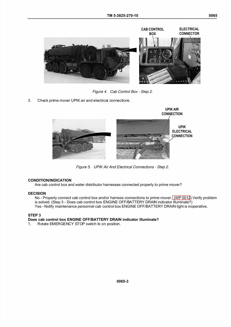
8/6/2019 TM 5-3825-270-10 ENGINEER MISSION MODULE WATER DISTRIBUTION
http://slidepdf.com/reader/full/tm-5-3825-270-10-engineer-mission-module-water-distribution 301/483
ELECTRICAL
CONNECTOR
CAB CONTROL
BOX
Figure 4. Cab Control Box - Step 2.
3. Check prime mover UPIK air and electrical connections.
UPIK AIR
CONNECTION
UPIK
ELECTRICAL
CONNECTION
Figure 5. UPIK Air And Electrical Connections - Step 2.
CONDITION/INDICATIONAre cab control box and water distributor harnesses connected properly to prime mover?
DECISIONNo - Properly connect cab control box and/or harness connections to prime mover. (WP 0012) Verify problemis solved. (Step 3 - Does cab control box ENGINE OFF/BATTERY DRAIN indicator illuminate?)Yes - Notify maintenance personnel cab control box ENGINE OFF/BATTERY DRAIN light is inoperative.
STEP 3Does cab control box ENGINE OFF/BATTERY DRAIN indicator illuminate?1. Rotate EMERGENCY STOP switch to on position.
TM 5-3825-270-10 0065
0065-3

8/6/2019 TM 5-3825-270-10 ENGINEER MISSION MODULE WATER DISTRIBUTION
http://slidepdf.com/reader/full/tm-5-3825-270-10-engineer-mission-module-water-distribution 302/483
EMERGENCY STOP SWITCH
Figure 6. Emergency Stop Switch - Step 3.
2. Observe cab control box ENGINE OFF/BATTERY DRAIN indicator.
CAB CONTROL
BOX ENGINE OFF/BATTERY
DRAIN INDICATOR
Figure 7. Cab Control Box Engine Off/Battery Drain Indicator - Step 3.
CONDITION/INDICATIONDoes cab control box ENGINE OFF/BATTERY DRAIN indicator illuminate?
DECISIONNo - Notify maintenance personnel cab control box ENGINE OFF/BATTERY DRAIN indicator is inoperative.Yes - Your original problem has been resolved.
END OF WORK PACKAGE
TM 5-3825-270-10 0065
0065-4
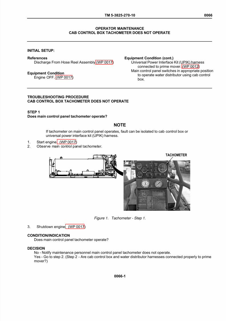
8/6/2019 TM 5-3825-270-10 ENGINEER MISSION MODULE WATER DISTRIBUTION
http://slidepdf.com/reader/full/tm-5-3825-270-10-engineer-mission-module-water-distribution 303/483
OPERATOR MAINTENANCECAB CONTROL BOX TACHOMETER DOES NOT OPERATE
INITIAL SETUP:
ReferencesDischarge From Hose Reel Assembly (WP 0017)
Equipment ConditionEngine OFF. (WP 0017)
Equipment Condition (cont.)Universal Power Interface Kit (UPIK) harness
connected to prime mover. (WP 0012)Main control panel switches in appropriate positio
to operate water distributor using cab controlbox.
TROUBLESHOOTING PROCEDURECAB CONTROL BOX TACHOMETER DOES NOT OPERATE
STEP 1Does main control panel tachometer operate?
NOTE
If tachometer on main control panel operates, fault can be isolated to cab control box or universal power interface kit (UPIK) harness.
1. Start engine. (WP 0017)2. Observe main control panel tachometer.
TACHOMETER
Figure 1. Tachometer - Step 1.
3. Shutdown engine. (WP 0017)
CONDITION/INDICATIONDoes main control panel tachometer operate?
DECISIONNo - Notify maintenance personnel main control panel tachometer does not operate.Yes - Go to step 2. (Step 2 - Are cab control box and water distributor harnesses connected properly to primemover?)
TM 5-3825-270-10 0066
0066-1

8/6/2019 TM 5-3825-270-10 ENGINEER MISSION MODULE WATER DISTRIBUTION
http://slidepdf.com/reader/full/tm-5-3825-270-10-engineer-mission-module-water-distribution 304/483
STEP 2Are cab control box and water distributor harnesses connected properly to prime mover?1. Push EMERGENCY STOP switch in to off position. (WP 0017)2. Check cab control box electrical connector.
ELECTRICAL
CONNECTOR
CAB CONTROL
BOX
Figure 2. Cab Control Box - Step 2.
3. Check prime mover UPIK air and electrical connections.
UPIK AIR
CONNECTION
UPIK
ELECTRICAL
CONNECTION
Figure 3. UPIK Air And Electrical Connections - Step 2.
CONDITION/INDICATIONAre cab control box and water distributor harnesses connected properly to prime mover?
DECISIONNo - Properly connect cab control box and/or harness connections to prime mover. (WP 0012) Verify problemis solved. (Step 3 - Does cab control box tachometer operate?)
Yes - Notify maintenance personnel cab control box tachometer does not operate.
STEP 3Does cab control box tachometer operate?1. Ensure water distributor is set up to be operated using cab control box. (WP 0012)2. Start engine. (WP 0017)3. Observe cab control box tachometer.
TM 5-3825-270-10 0066
0066-2

8/6/2019 TM 5-3825-270-10 ENGINEER MISSION MODULE WATER DISTRIBUTION
http://slidepdf.com/reader/full/tm-5-3825-270-10-engineer-mission-module-water-distribution 305/483
CAB CONTROL
BOX TACHOMETER
Figure 4. Cab Control Box Tachometer - Step 3.4. Shutdown engine. (WP 0017)
CONDITION/INDICATIONDoes cab control box tachometer operate?
DECISIONNo - Notify maintenance personnel cab control box tachometer does not operate.Yes - Your original problem has been resolved.
END OF WORK PACKAGE
TM 5-3825-270-10 0066
0066-3/4 blank

8/6/2019 TM 5-3825-270-10 ENGINEER MISSION MODULE WATER DISTRIBUTION
http://slidepdf.com/reader/full/tm-5-3825-270-10-engineer-mission-module-water-distribution 306/483
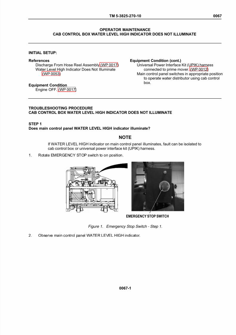
8/6/2019 TM 5-3825-270-10 ENGINEER MISSION MODULE WATER DISTRIBUTION
http://slidepdf.com/reader/full/tm-5-3825-270-10-engineer-mission-module-water-distribution 307/483
OPERATOR MAINTENANCECAB CONTROL BOX WATER LEVEL HIGH INDICATOR DOES NOT ILLUMINATE
INITIAL SETUP:
ReferencesDischarge From Hose Reel Assembly (WP 0017)Water Level High Indicator Does Not Illuminate
(WP 0053)
Equipment ConditionEngine OFF. (WP 0017)
Equipment Condition (cont.)Universal Power Interface Kit (UPIK) harness
connected to prime mover. (WP 0012)Main control panel switches in appropriate positio
to operate water distributor using cab controlbox.
TROUBLESHOOTING PROCEDURECAB CONTROL BOX WATER LEVEL HIGH INDICATOR DOES NOT ILLUMINATE
STEP 1Does main control panel WATER LEVEL HIGH indicator illuminate?
NOTE
If WATER LEVEL HIGH indicator on main control panel illuminates, fault can be isolated tocab control box or universal power interface kit (UPIK) harness.
1. Rotate EMERGENCY STOP switch to on position.
EMERGENCY STOP SWITCH
Figure 1. Emergency Stop Switch - Step 1.
2. Observe main control panel WATER LEVEL HIGH indicator.
TM 5-3825-270-10 0067
0067-1

8/6/2019 TM 5-3825-270-10 ENGINEER MISSION MODULE WATER DISTRIBUTION
http://slidepdf.com/reader/full/tm-5-3825-270-10-engineer-mission-module-water-distribution 308/483
WATER LEVEL
HIGH INDICATOR
Figure 2. Water Level High indicator - Step 1.
3. Push EMERGENCY STOP switch in to off position. (WP 0017)
CONDITION/INDICATIONDoes main control panel WATER LEVEL HIGH indicator illuminate?
DECISIONNo - Go to main control panel Water Level High Indicator Does Not Illuminate. (WP 0053)Yes - Go to step 2. (Step 2 - Are cab control box and water distributor harnesses connected properly to primemover?)
STEP 2Are cab control box and water distributor harnesses connected properly to prime mover?1. Check cab control box electrical connector.
ELECTRICAL
CONNECTOR
CAB CONTROL
BOX
Figure 3. Cab Control Box - Step 2.
2. Check prime mover UPIK air and electrical connections.
TM 5-3825-270-10 0067
0067-2

8/6/2019 TM 5-3825-270-10 ENGINEER MISSION MODULE WATER DISTRIBUTION
http://slidepdf.com/reader/full/tm-5-3825-270-10-engineer-mission-module-water-distribution 309/483
UPIK AIR
CONNECTION
UPIK
ELECTRICAL
CONNECTION
Figure 4. UPIK Air And Electrical Connections - Step 2.
CONDITION/INDICATIONAre cab control box and water distributor harnesses connected properly to prime mover?
DECISIONNo - Properly connect cab control box and/or harness connections to prime mover. (WP 0012) Verify problemis solved. (Step 3 - Does cab control box WATER LEVEL HIGH indicator illuminate?)Yes - Notify maintenance personnel cab control box WATER LEVEL HIGH INDICATOR does not illuminate.
STEP 3Does cab control box WATER LEVEL HIGH indicator illuminate?1. Rotate EMERGENCY STOP switch to on position.
EMERGENCY STOP SWITCH
Figure 5. Emergency Stop Switch - Step 3.
2. Observe cab control box WATER LEVEL HIGH indicator.
TM 5-3825-270-10 0067
0067-3

8/6/2019 TM 5-3825-270-10 ENGINEER MISSION MODULE WATER DISTRIBUTION
http://slidepdf.com/reader/full/tm-5-3825-270-10-engineer-mission-module-water-distribution 310/483
CAB CONTROL BOX WATER
LEVEL HIGH INDICATOR
Figure 6. Cab Control Box Water Level High Indicator - Step 3.
CONDITION/INDICATIONDoes cab control box WATER LEVEL HIGH indicator illuminate?
DECISIONNo - Notify maintenance personnel cab control box WATER LEVEL HIGH indicator does not illuminate.Yes - Problem solved.
END OF WORK PACKAGE
TM 5-3825-270-10 0067
0067-4

8/6/2019 TM 5-3825-270-10 ENGINEER MISSION MODULE WATER DISTRIBUTION
http://slidepdf.com/reader/full/tm-5-3825-270-10-engineer-mission-module-water-distribution 311/483
OPERATOR MAINTENANCECAB CONTROL BOX WATER LEVEL LOW INDICATOR DOES NOT ILLUMINATE
INITIAL SETUP:
ReferencesDischarge From Hose Reel Assembly (WP 0017)Water Level Low Indicator Does Not Illuminate
(WP 0054)
Equipment ConditionEngine OFF. (WP 0017)
Equipment Condition (cont.)Universal Power Interface Kit (UPIK) harness
connected to prime mover. (WP 0012)Main control panel switches in appropriate positio
to operate water distributor using cab controlbox.
TROUBLESHOOTING PROCEDURECAB CONTROL BOX WATER LEVEL LOW INDICATOR DOES NOT ILLUMINATE
STEP 1Does main control panel WATER LEVEL LOW indicator illuminate?
NOTE
If WATER LEVEL LOW indicator on main control panel illuminates, fault can be isolated tocab control box or universal power interface kit (UPIK) harness.
1. Rotate EMERGENCY STOP switch to on position.
EMERGENCY STOP SWITCH
Figure 1. Emergency Stop Switch - Step 1.
2. Observe main control panel WATER LEVEL LOW indicator.
TM 5-3825-270-10 0068
0068-1

8/6/2019 TM 5-3825-270-10 ENGINEER MISSION MODULE WATER DISTRIBUTION
http://slidepdf.com/reader/full/tm-5-3825-270-10-engineer-mission-module-water-distribution 312/483
WATER LEVEL
LOW INDICATOR
Figure 2. Water Level Low Indicator - Step 1.
3. Push EMERGENCY STOP switch in to off position.
CONDITION/INDICATION
Does main control panel WATER LEVEL LOW indicator illuminate?
DECISIONNo - Go to main control panel Water Level Low Indicator Does Not Illuminate. (WP 0054)Yes - Go to step 2. (Step 2 - Are cab control box and water distributor harnesses connected properly to primemover?)
STEP 2Are cab control box and water distributor harnesses connected properly to prime mover?1. Check cab control box electrical connector.
ELECTRICAL
CONNECTOR
CAB CONTROL
BOX
Figure 3. Cab Control Box - Step 2.
2. Check prime mover UPIK air and electrical connections.
TM 5-3825-270-10 0068
0068-2

8/6/2019 TM 5-3825-270-10 ENGINEER MISSION MODULE WATER DISTRIBUTION
http://slidepdf.com/reader/full/tm-5-3825-270-10-engineer-mission-module-water-distribution 313/483
UPIK AIR
CONNECTION
UPIK
ELECTRICAL
CONNECTION
Figure 4. UPIK Air And Electrical Connections - Step 2.
CONDITION/INDICATIONAre cab control box and water distributor harnesses connected properly to prime mover?
DECISIONNo - Properly connect cab control box and/or harness connections to prime mover. (WP 0012) Verify problemis solved. (Step 3 - Does cab control box WATER LEVEL LOW indicator illuminate?)Yes - Notify maintenance personnel cab control box WATER LEVEL LOW INDICATOR does not illuminate.
STEP 3Does cab control box WATER LEVEL LOW indicator illuminate?1. Rotate EMERGENCY STOP switch to on position.
EMERGENCY STOP SWITCH
Figure 5. Emergency Stop Switch - Step 3.
2. Observe cab control box WATER LEVEL LOW indicator.
TM 5-3825-270-10 0068
0068-3

8/6/2019 TM 5-3825-270-10 ENGINEER MISSION MODULE WATER DISTRIBUTION
http://slidepdf.com/reader/full/tm-5-3825-270-10-engineer-mission-module-water-distribution 314/483
CAB CONTROL
BOX WATER
LEVEL LOW
INDICATOR
Figure 6. Cab Control Box Water Level Low Indicator - Step 3.
CONDITION/INDICATIONDoes cab control box WATER LEVEL LOW indicator illuminate?
DECISIONNo - Notify maintenance personnel cab control box WATER LEVEL LOW indicator does not illuminate.
Yes - Problem solved.
END OF WORK PACKAGE
TM 5-3825-270-10 0068
0068-4

8/6/2019 TM 5-3825-270-10 ENGINEER MISSION MODULE WATER DISTRIBUTION
http://slidepdf.com/reader/full/tm-5-3825-270-10-engineer-mission-module-water-distribution 315/483
OPERATOR MAINTENANCECAB CONTROL BOX LIGHTS SWITCH DOES NOT OPERATE
INITIAL SETUP:
ReferencesDischarge From Hose Reel Assembly (WP 0017)Operating Lights (WP 0006)Work Lights Do Not Operate (WP 0043)
Equipment ConditionEngine OFF. (WP 0017)
Equipment Condition (cont.)Universal Power Interface Kit (UPIK) harness
connected to prime mover. (WP 0012)Main control panel switches in appropriate positio
to operate water distributor using cab controlbox.
TROUBLESHOOTING PROCEDURECAB CONTROL BOX LIGHTS SWITCH DOES NOT OPERATE
STEP 1Do work lights operate using main control panel LIGHTS switch?
NOTE
If work lights operate using LIGHTS switch on main control panel, fault can be isolated to cabcontrol box or universal power interface kit (UPIK) harness.
1. Attempt to operate work lights using main control panel. (WP 0006)2. Observe work lights. (WP 0006)
CONDITION/INDICATIONDo work lights operate using main control panel LIGHTS switch?
DECISIONNo - Go to Work Lights Do Not Operate. (WP 0043)Yes - Go to step 2. (Step 2 - Are cab control box and water distributor harnesses connected properly to primemover?)
STEP 2Are cab control box and water distributor harnesses connected properly to prime mover?1. Push EMERGENCY STOP switch in to off position. (WP 0006)2. Check cab control box electrical connector.
TM 5-3825-270-10 0069
0069-1

8/6/2019 TM 5-3825-270-10 ENGINEER MISSION MODULE WATER DISTRIBUTION
http://slidepdf.com/reader/full/tm-5-3825-270-10-engineer-mission-module-water-distribution 316/483
ELECTRICAL
CONNECTOR
CAB CONTROL
BOX
Figure 1. Cab Control Box - Step 2.
3. Check prime mover UPIK air and electrical connections.
UPIK AIR
CONNECTION
UPIK
ELECTRICAL
CONNECTION
Figure 2. UPIK Air And Electrical Connections - Step 2.
CONDITION/INDICATIONAre cab control box and water distributor harnesses connected properly to prime mover?
DECISIONNo - Properly connect cab control box and/or harness connections to prime mover. (WP 0012) Verify problemis solved. (Step 3 - Does cab control box LIGHTS switch operate?)Yes - Notify maintenance personnel cab control box LIGHTS switch does not operate.
STEP 3Does cab control box LIGHTS switch operate?1. Ensure water distributor is set up to be operated using cab control box.
2. Attempt to operate work lights using cab control box. (WP 0017)3. Observe work lights. (WP 0006)
CONDITION/INDICATIONDoes cab control box LIGHTS switch operate?
TM 5-3825-270-10 0069
0069-2

8/6/2019 TM 5-3825-270-10 ENGINEER MISSION MODULE WATER DISTRIBUTION
http://slidepdf.com/reader/full/tm-5-3825-270-10-engineer-mission-module-water-distribution 317/483
DECISIONNo - Notify maintenance personnel cab control box LIGHTS switch does not operate.Yes - Your original problem has been resolved.
END OF WORK PACKAGE
TM 5-3825-270-10 0069
0069-3/4 blank

8/6/2019 TM 5-3825-270-10 ENGINEER MISSION MODULE WATER DISTRIBUTION
http://slidepdf.com/reader/full/tm-5-3825-270-10-engineer-mission-module-water-distribution 318/483
8/6/2019 TM 5-3825-270-10 ENGINEER MISSION MODULE WATER DISTRIBUTION
http://slidepdf.com/reader/full/tm-5-3825-270-10-engineer-mission-module-water-distribution 319/483
CHAPTER 4
PREVENTIVE MAINTENANCE CHECKS AND SERVICES (PMCS)
TM 5-3825-270-10

8/6/2019 TM 5-3825-270-10 ENGINEER MISSION MODULE WATER DISTRIBUTION
http://slidepdf.com/reader/full/tm-5-3825-270-10-engineer-mission-module-water-distribution 320/483
8/6/2019 TM 5-3825-270-10 ENGINEER MISSION MODULE WATER DISTRIBUTION
http://slidepdf.com/reader/full/tm-5-3825-270-10-engineer-mission-module-water-distribution 321/483
OPERATOR MAINTENANCEOPERATOR PREVENTIVE MAINTENANCE CHECKS AND SERVICES (PMCS) INTRODUCTION
GENERAL
To ensure that the water distributor is ready for operation at all times, it must be inspected on a regular basis so thdefects may be found and corrected before they result in serious damage, equipment failure, or injury to personnePMCS tasks contains systematic instructions on inspections, lubrications, adjustments, and corrections to beperformed by the operator to keep your equipment in good operating condition and ready for its primary mission.
EXPLANATION OF TABLE ENTRIES
NOTE
The WARNINGs and CAUTIONs appearing in your PMCS table must always be observed.WARNINGs and CAUTIONs appear before applicable procedures. You must observe theseWARNINGs to prevent serious injury to yourself and others, and CAUTIONs to prevent your equipment from being damaged.
Item Number (Item No.) Column. Numbers in this column are for reference. When completing DA Form 2404 or DA Form 5988-E (Equipment Inspection and Maintenance Worksheet), include the item number for the check/servindicating a fault. Item numbers also appear in the order that you must perform checks and services for the intervalisted.
Interval Column.This column tells you when you must perform the procedure in the procedure column.• Before procedures must be done immediately before you operate the equipment.
• During procedures must be done while you are operating the equipment.
• After procedures must be done immediately after you have operated the equipment.
• Weekly procedures must be done once each week.
• Monthly procedures must be done once each month.
• Semi-Annual procedures must be done every six months.
Location, Item to Check/Service Column. This column provides the location and item to be checked or serviced
Procedure Column. This column gives the procedure you must perform to know if the equipment is ready or available for its intended mission or for operation. You must perform the procedure at the time stated in the intervacolumn.
Not Fully Mission Capable If: Column. Information in this column tells you what faults will keep your equipmentfrom being capable of performing its primary mission. If you perform check/service procedures that show faults listin this column, the equipment is not mission-capable. Follow standard operating procedures for maintaining theequipment or reporting equipment failure.
GENERAL PMCS PROCEDURES
Always perform PMCS in the same order. With experience, you should be able to identify problems easily. If themachine does not perform as required, refer to the appropriate troubleshooting task. If anything looks wrong andyou can't fix it, write it on your DA Form 2404 or DA Form 5988-E. If you find something seriously wrong,IMMEDIATELY report it to your supervisor.
Before performing preventive maintenance, read all the checks required for the applicable interval and prepareeverything needed to make all the checks. For example, you'll always need a rag (WP 0088, Table 1, Item 30) or two.
TM 5-3825-270-10 0070
0070-1

8/6/2019 TM 5-3825-270-10 ENGINEER MISSION MODULE WATER DISTRIBUTION
http://slidepdf.com/reader/full/tm-5-3825-270-10-engineer-mission-module-water-distribution 322/483
GENERAL PMCS PROCEDURES - Continued
Keep It Clean. Dirt, grease, oil, and debris get in the way and may cover up a serious problem. Clean as you workand as needed. Use solvent cleaning compound (WP 0088, Table 1, Item 4, 5, 6, 7, 8, 9) on all metal surfaces. Usedetergent (WP 0088, Table 1, Item 12) and water when you clean rubber, plastic, and painted surfaces.
Hazardous Waste Disposal. Ensure all spills are cleaned up and disposed of in accordance with local policy and
ordinances.
Rust and Corrosion.Check metal parts for rust and corrosion. If any bare metal or corrosion exists, clean and applya light coat of lubricating oil (WP 0088, Table 1, Item 26, 27, 28). Report it to your supervisor.
Bolts, Nuts, and Screws. Check bolts, nuts, and screws for obvious looseness and missing, bent, or brokencondition. You can't try them all with a tool, but look for chipped paint, bare metal, or rust around bolt heads. If youfind one you think is loose, tighten it.
Welds. Look for loose or chipped paint, rust, or gaps where parts are welded together. If you find a bad weld, reportit to your supervisor.
Electric Wires and Connectors.Look for cracked or broken insulation, bare wires, and loose or broken connectors.Tighten loose connectors and ensure that the wires are in good condition.
Hoses and Fluid Lines. Look for wear, damage, and signs of leaks. Ensure that clamps and fittings are tight. Wetspots indicate leaks, but a stain around a fitting or connector can also mean a leak. If a leak comes from a loosefitting or connector, tighten it. If something is broken or worn out, report it to your supervisor.
Fluid Leakage. It is necessary for you to know how fluid leakage affects the status of your equipment. The followingare definitions of the types/classes of leakage you need to know to be able to determine the status of your machine.Learn and be familiar with them, and remember - when in doubt, notify your supervisor.
NOTE
• Operation is allowable with Class I and Class II leakage. WHEN IN DOUBT, NOTIFYYOUR SUPERVISOR.
• When operating with Class I or Class II leaks, check fluid levels more frequently. ClassIII leaks must be reported immediately to your supervisor. Failure to do this will result in
damage to machine and/or components.• Notify Field Maintenance of any leaks the operator cannot fix.
Table 1. Leakage Definitions for PMCS.
Class I Leakage Indicated by wetness or discoloration, but not greatenough to form drops.
Class II Leakage Great enough to form drops, but not enough to causedrops to drip from the item being checked/inspected.
Class III Leakage Great enough to form drops that fall from the item beingchecked/inspected.
LUBRICATION PROCEDURES
Included in this PMCS are lubrication services to be performed by the operator.
Keep all lubricants in an environmental storage container and store in a clean, dry place away from extreme heat.Keep container covers clean and do not allow dust, dirt, or other foreign material to mix with lubricants. Keeplubrication equipment clean and ready for use. Clean top of container before opening.
TM 5-3825-270-10 0070
0070-2

8/6/2019 TM 5-3825-270-10 ENGINEER MISSION MODULE WATER DISTRIBUTION
http://slidepdf.com/reader/full/tm-5-3825-270-10-engineer-mission-module-water-distribution 323/483
LUBRICATION PROCEDURES - Continued
Clean area around lubrication points with solvent cleaning compound or equivalent before lubricating equipment.Keep all external parts of equipment not requiring lubrication free of lubricants. After lubrication, wipe off excesslubricant to prevent accumulation of foreign matter.
Maintain a record of lubrication performed and report any problems noted during lubrication. Refer to DA PAM 750
for forms and procedures to record and report any findings.
NOTE
Only lubricants authorized for use by the operator are listed in this KEY.
Table 2. Key.
LUBRICANT/COMPONENT
REFILL CAPACITYEXPECTEDTEMPERATURES
OE/HDO 15W40/Engine Crankcase
13.96 qt (13.2 L) ALLTEMPERATURES
GAA Grease,Automotive andArtillery
As Required ALLTEMPERATURES
Every 8 to 15 hours of Operation:Check Engine Oil Level. When checking the oil level, the engine should be level and must not be running.
Remove any dirt in the dipstick (Figure 1, Item 1) area.
1
Figure 1. Dipstick.
Check oil level at the dipstick (Figure 1, Item 1). Fill as necessary up to the top line on the dipstick.
Every 24 Hours of Operation:Lightly lubricate two water turret lube points with GAA after each 24 hours of accumulated use.
TM 5-3825-270-10 0070
0070-3
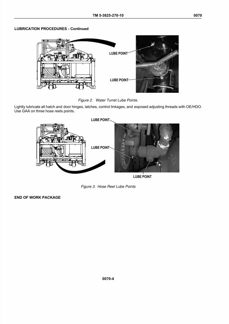
8/6/2019 TM 5-3825-270-10 ENGINEER MISSION MODULE WATER DISTRIBUTION
http://slidepdf.com/reader/full/tm-5-3825-270-10-engineer-mission-module-water-distribution 324/483
LUBRICATION PROCEDURES - Continued
LUBE POINT
LUBE POINT
Figure 2. Water Turret Lube Points.
Lightly lubricate all hatch and door hinges, latches, control linkages, and exposed adjusting threads with OE/HDO.Use GAA on three hose reels points.
LUBE POINT
LUBE POINT
LUBE POINT
Figure 3. Hose Reel Lube Points
END OF WORK PACKAGE
TM 5-3825-270-10 0070
0070-4

8/6/2019 TM 5-3825-270-10 ENGINEER MISSION MODULE WATER DISTRIBUTION
http://slidepdf.com/reader/full/tm-5-3825-270-10-engineer-mission-module-water-distribution 325/483
OPERATOR MAINTENANCEOPERATOR PREVENTIVE MAINTENANCE CHECKS AND SERVICES (PMCS)
INITIAL SETUP:
Not Applicable
Table 1. OPERATOR PREVENTIVE MAINTENANCE CHECKS AND SERVICES (PMCS)
ITEMNO. INTERVAL
ITEM TO BE CHECKEDOR SERVICED PROCEDURE
EQUIPMENT NOTREADY/
AVAILABLE IF:
1 Before Ladder WARNING
Keep hands and fingersclear of ladder rungs andsides when placing ladder inthe stowed position. Failureto comply may result in in-
jury or death to personnel.
1. Check that ladder is present andsecured with tie down strap:
a. Tie down strap
Ladder is miss-ing or has dam-
age that will im-pair operation.
TM 5-3825-270-10 0071
0071-1

8/6/2019 TM 5-3825-270-10 ENGINEER MISSION MODULE WATER DISTRIBUTION
http://slidepdf.com/reader/full/tm-5-3825-270-10-engineer-mission-module-water-distribution 326/483
Table 1. OPERATOR PREVENTIVE MAINTENANCE CHECKS AND SERVICES (PMCS) - Continued
ITEMNO. INTERVAL
ITEM TO BE CHECKEDOR SERVICED PROCEDURE
EQUIPMENT NOTREADY/
AVAILABLE IF:
LADDER TIE DOWN STRAP
Figure 1. Ladder.
2 Before Petcock Valves 1. Ensure that all petcock valvesare closed.
Any petcockvalve is missing,or has damagethat will impair operation.
TM 5-3825-270-10 0071
0071-2

8/6/2019 TM 5-3825-270-10 ENGINEER MISSION MODULE WATER DISTRIBUTION
http://slidepdf.com/reader/full/tm-5-3825-270-10-engineer-mission-module-water-distribution 327/483
Table 1. OPERATOR PREVENTIVE MAINTENANCE CHECKS AND SERVICES (PMCS) - Continued
ITEMNO. INTERVAL
ITEM TO BE CHECKEDOR SERVICED PROCEDURE
EQUIPMENT NOTREADY/
AVAILABLE IF:
PETCOCK
PETCOCK
PETCOCK VALVES
Figure 2. Petcock Valves.
3 Before Engine 1. Remove rear engine accesscover (WP 0082). Check for evidence of leakage of the followingfluids on, or under water distributor:a. Oil
b. Antifreeze
c. Fuel
Class III or anyfuel leak is evi-dent.
TM 5-3825-270-10 0071
0071-3

8/6/2019 TM 5-3825-270-10 ENGINEER MISSION MODULE WATER DISTRIBUTION
http://slidepdf.com/reader/full/tm-5-3825-270-10-engineer-mission-module-water-distribution 328/483
Table 1. OPERATOR PREVENTIVE MAINTENANCE CHECKS AND SERVICES (PMCS) - Continued
ITEMNO. INTERVAL
ITEM TO BE CHECKEDOR SERVICED PROCEDURE
EQUIPMENT NOTREADY/
AVAILABLE IF:
ENGINE
Figure 3. Engine.
4 Before Engine Oil WARNING
Prolonged contact with lubri-cating oil may cause skinrash. Immediately wash skinand clothing thoroughly andremove saturated clothing
that comes in contact withlubricating oil. Keep areawell-ventilated to keepfumes at a minimum. Failureto comply may result in in-
jury or death to personnel.
TM 5-3825-270-10 0071
0071-4

8/6/2019 TM 5-3825-270-10 ENGINEER MISSION MODULE WATER DISTRIBUTION
http://slidepdf.com/reader/full/tm-5-3825-270-10-engineer-mission-module-water-distribution 329/483
Table 1. OPERATOR PREVENTIVE MAINTENANCE CHECKS AND SERVICES (PMCS) - Continued
ITEMNO. INTERVAL
ITEM TO BE CHECKEDOR SERVICED PROCEDURE
EQUIPMENT NOTREADY/
AVAILABLE IF:
1. Check that engine oil level isbetween High and Low line ondipstick.
Class III leak isevident, engineoil level is notwithin specifiedrange, or dip-stick is missingor broken.
LOW LINE HIGH LINE
DIPSTICK
Figure 4. Engine Oil.
5 Before Engine Coolant 1. Check that engine coolant levelis half full in coolant reservoir.
Class III leak isevident, coolantlevel is low, or reservoir is bro-ken.
TM 5-3825-270-10 0071
0071-5

8/6/2019 TM 5-3825-270-10 ENGINEER MISSION MODULE WATER DISTRIBUTION
http://slidepdf.com/reader/full/tm-5-3825-270-10-engineer-mission-module-water-distribution 330/483
Table 1. OPERATOR PREVENTIVE MAINTENANCE CHECKS AND SERVICES (PMCS) - Continued
ITEMNO. INTERVAL
ITEM TO BE CHECKEDOR SERVICED PROCEDURE
EQUIPMENT NOTREADY/
AVAILABLE IF:
COOLANT RESERVOIR
Figure 5. Engine Coolant.
6 Before Fuel/Water Separator WARNING
• DO NOT smoke or
permit any open flamein area of water distributor while you areservicing fuel system.Be sure hose nozzle isgrounded against filler tube during refueling toprevent static electricity.Failure to comply mayresult in injury or death.
• DO NOT perform fuelsystem checks,
TM 5-3825-270-10 0071
0071-6

8/6/2019 TM 5-3825-270-10 ENGINEER MISSION MODULE WATER DISTRIBUTION
http://slidepdf.com/reader/full/tm-5-3825-270-10-engineer-mission-module-water-distribution 331/483
Table 1. OPERATOR PREVENTIVE MAINTENANCE CHECKS AND SERVICES (PMCS) - Continued
ITEMNO. INTERVAL
ITEM TO BE CHECKEDOR SERVICED PROCEDURE
EQUIPMENT NOTREADY/
AVAILABLE IF:
inspections, or
maintenance whilesmoking or near fire,flames, or sparks. Fuelmay ignite, causinginjury, death or damageto equipment.
• Operating personnelmust wear fuel-resistantgloves when handlingfuels. If exposed to fuel,promptly wash exposedskin and change fuel-soaked clothing. Failure
to comply may result ininjury or death topersonnel. Failure tocomply may result ininjury or death topersonnel.
NOTE
Drain fuel into suitable con-tainer.
1. Turn drain cock on bottom of bowl to open contaminant drain
valve. Keep drain open until onlypure fuel is flowing out of drain tube.Close drain valve by turning draincock.
TM 5-3825-270-10 0071
0071-7

8/6/2019 TM 5-3825-270-10 ENGINEER MISSION MODULE WATER DISTRIBUTION
http://slidepdf.com/reader/full/tm-5-3825-270-10-engineer-mission-module-water-distribution 332/483
Table 1. OPERATOR PREVENTIVE MAINTENANCE CHECKS AND SERVICES (PMCS) - Continued
ITEMNO. INTERVAL
ITEM TO BE CHECKEDOR SERVICED PROCEDURE
EQUIPMENT NOTREADY/
AVAILABLE IF:
FUEL/WATER SEPARATOR
DRAIN COCKBOWL
Figure 6. Fuel/Water Separator.
2. Check fuel/water separator for leaks and damage.
Any fuel leak isevident.
7 Before Engine Drive Belt 1. Visually inspect engine drive belt. Belt is missing,frayed or cracked.
TM 5-3825-270-10 0071
0071-8
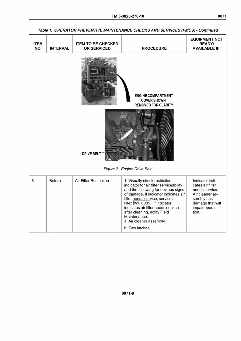
8/6/2019 TM 5-3825-270-10 ENGINEER MISSION MODULE WATER DISTRIBUTION
http://slidepdf.com/reader/full/tm-5-3825-270-10-engineer-mission-module-water-distribution 333/483
Table 1. OPERATOR PREVENTIVE MAINTENANCE CHECKS AND SERVICES (PMCS) - Continued
ITEMNO. INTERVAL
ITEM TO BE CHECKEDOR SERVICED PROCEDURE
EQUIPMENT NOTREADY/
AVAILABLE IF:
DRIVE BELT
ENGINE COMPARTMENT
COVER SHOWN
REMOVED FOR CLARITY
Figure 7. Engine Drive Belt.
8 Before Air Filter Restriction 1. Visually check restrictionindicator for air filter serviceabilityand the following for obvious signsof damage. If indicator indicates air filter needs service, service air filter (WP 0085). If indicator indicates air filter needs serviceafter cleaning, notify FieldMaintenance.a. Air cleaner assembly
b. Two latches
Indicator indi-cates air filter needs service.Air cleaner as-sembly hasdamage that willimpair opera-tion.
TM 5-3825-270-10 0071
0071-9

8/6/2019 TM 5-3825-270-10 ENGINEER MISSION MODULE WATER DISTRIBUTION
http://slidepdf.com/reader/full/tm-5-3825-270-10-engineer-mission-module-water-distribution 334/483
Table 1. OPERATOR PREVENTIVE MAINTENANCE CHECKS AND SERVICES (PMCS) - Continued
ITEMNO. INTERVAL
ITEM TO BE CHECKEDOR SERVICED PROCEDURE
EQUIPMENT NOTREADY/
AVAILABLE IF:
AIR CLEANERASSEMBLY
LATCHRESTRICTION
INDICATOR
Figure 8.
Air Cleaner.
9 Before Batteries WARNING
BATTERIES
To avoid shock whendisconnecting the batteries,ensure that the negativeterminal is disconnected firstand the system power isturned off. Failure to complymay result in serious injury
TM 5-3825-270-10 0071
0071-10

8/6/2019 TM 5-3825-270-10 ENGINEER MISSION MODULE WATER DISTRIBUTION
http://slidepdf.com/reader/full/tm-5-3825-270-10-engineer-mission-module-water-distribution 335/483
Table 1. OPERATOR PREVENTIVE MAINTENANCE CHECKS AND SERVICES (PMCS) - Continued
ITEMNO. INTERVAL
ITEM TO BE CHECKEDOR SERVICED PROCEDURE
EQUIPMENT NOTREADY/
AVAILABLE IF:
or death to personnel and/or
damage to equipment.
1. Remove battery box cover (WP 0081). Check the batteries,electrolyte level, and the followinghardware for presence, andobvious signs of damage:a. Terminals
b. Terminal covers
c. Battery hold down
d. Rubber t-handles
Terminals, bat-tery cables, or battery holddown has dam-age that will im-pair operation.Cells are low,empty, or cracked.
BATTERY
HOLD DOWN
RUBBER T-HANDLE
TERMINAL
CELLS
TERMINAL
COVER
BATTERIES
Figure 9. Batteries.
10 Before NATO Slave 1. Check NATO slave and followinghardware for presence and obvioussigns of damage:a. Cap
b. Tether
NATO slave hasany damagethat will impair operation.
TM 5-3825-270-10 0071
0071-11
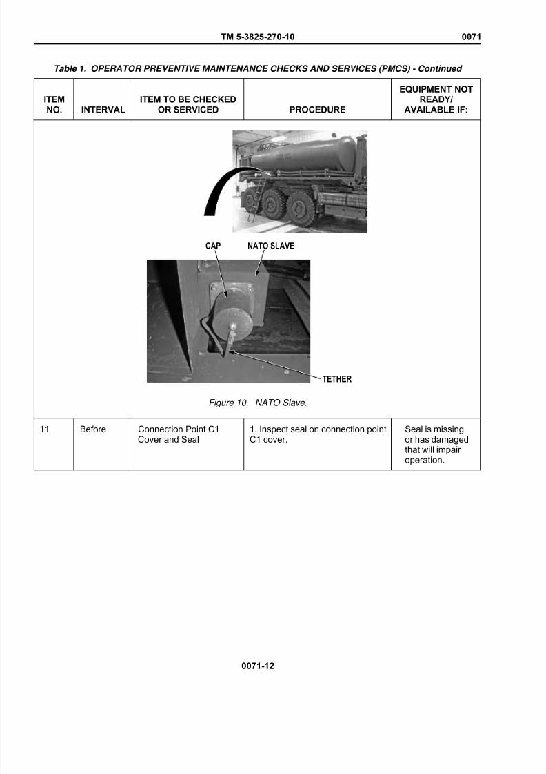
8/6/2019 TM 5-3825-270-10 ENGINEER MISSION MODULE WATER DISTRIBUTION
http://slidepdf.com/reader/full/tm-5-3825-270-10-engineer-mission-module-water-distribution 336/483
Table 1. OPERATOR PREVENTIVE MAINTENANCE CHECKS AND SERVICES (PMCS) - Continued
ITEMNO. INTERVAL
ITEM TO BE CHECKEDOR SERVICED PROCEDURE
EQUIPMENT NOTREADY/
AVAILABLE IF:
TETHER
CAP NATO SLAVE
Figure 10.
NATO Slave.
11 Before Connection Point C1Cover and Seal
1. Inspect seal on connection pointC1 cover.
Seal is missingor has damagedthat will impair operation.
TM 5-3825-270-10 0071
0071-12

8/6/2019 TM 5-3825-270-10 ENGINEER MISSION MODULE WATER DISTRIBUTION
http://slidepdf.com/reader/full/tm-5-3825-270-10-engineer-mission-module-water-distribution 337/483
Table 1. OPERATOR PREVENTIVE MAINTENANCE CHECKS AND SERVICES (PMCS) - Continued
ITEMNO. INTERVAL
ITEM TO BE CHECKEDOR SERVICED PROCEDURE
EQUIPMENT NOTREADY/
AVAILABLE IF:
CONNECTION C1
CONNECTION
POINT COVER
SEAL
Figure 11. Connection Point C1.
12 Before Hoses and RetainingScrews
1. Check that hoses are present,and the following hardware for obvious signs of damage:a. Retaining screws
b. Hose connection covers
c. Hose connection cover chains
Hoses are miss-ing, or havedamage that willimpair opera-tion.
TM 5-3825-270-10 0071
0071-13

8/6/2019 TM 5-3825-270-10 ENGINEER MISSION MODULE WATER DISTRIBUTION
http://slidepdf.com/reader/full/tm-5-3825-270-10-engineer-mission-module-water-distribution 338/483
Table 1. OPERATOR PREVENTIVE MAINTENANCE CHECKS AND SERVICES (PMCS) - Continued
ITEMNO. INTERVAL
ITEM TO BE CHECKEDOR SERVICED PROCEDURE
EQUIPMENT NOTREADY/
AVAILABLE IF:
RETAINING
SCREW
HOSE CONNECTION
COVER CHAIN
HOSE CONNECTION
COVER
HOSE
Figure 12. Hoses and Retaining Screws.
13 Before Floating Strainer 1. Check that strainer is presentand the following hardware for presence and obvious signs of damage.a. Tie down strap
b. Cap
c. Chain
Floating strainer is missing or has damagethat will impair operation.
TM 5-3825-270-10 0071
0071-14
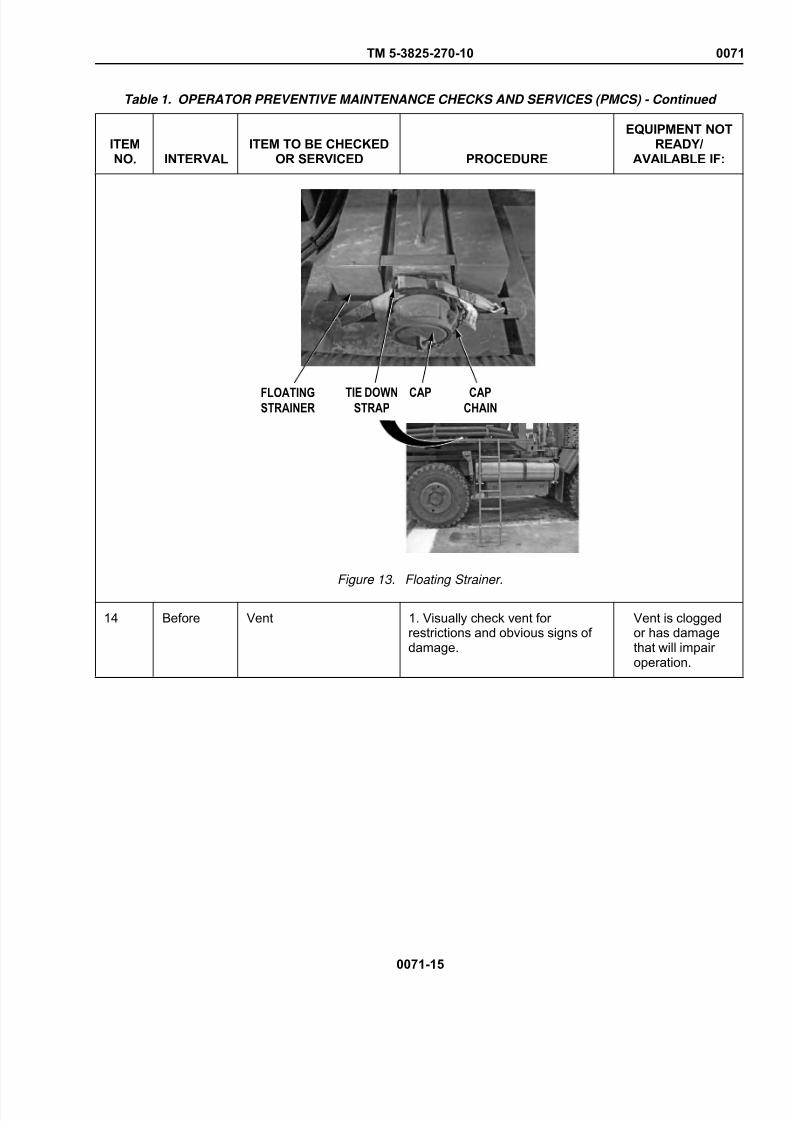
8/6/2019 TM 5-3825-270-10 ENGINEER MISSION MODULE WATER DISTRIBUTION
http://slidepdf.com/reader/full/tm-5-3825-270-10-engineer-mission-module-water-distribution 339/483
Table 1. OPERATOR PREVENTIVE MAINTENANCE CHECKS AND SERVICES (PMCS) - Continued
ITEMNO. INTERVAL
ITEM TO BE CHECKEDOR SERVICED PROCEDURE
EQUIPMENT NOTREADY/
AVAILABLE IF:
FLOATINGSTRAINER
TIE DOWNSTRAP
CAP CAPCHAIN
Figure 13. Floating Strainer.
14 Before Vent 1. Visually check vent for restrictions and obvious signs of damage.
Vent is cloggedor has damagethat will impair operation.
TM 5-3825-270-10 0071
0071-15

8/6/2019 TM 5-3825-270-10 ENGINEER MISSION MODULE WATER DISTRIBUTION
http://slidepdf.com/reader/full/tm-5-3825-270-10-engineer-mission-module-water-distribution 340/483
Table 1. OPERATOR PREVENTIVE MAINTENANCE CHECKS AND SERVICES (PMCS) - Continued
ITEMNO. INTERVAL
ITEM TO BE CHECKEDOR SERVICED PROCEDURE
EQUIPMENT NOTREADY/
AVAILABLE IF:
VENT
Figure 14. Vent.
15 Before Tank 1. Check the tank and welds for cracks, leaks, and obvious signs of damage.
Class III leak isevident, tankhas cracks or obvious dam-age that will im-pair operation.
TANK
Figure 15. Tank.
16 Before Water Level Indicator 1. Check the following hardware for presence and obvious signs of damage:
Switch(es),needle, gauge,wiring or con-
TM 5-3825-270-10 0071
0071-16

8/6/2019 TM 5-3825-270-10 ENGINEER MISSION MODULE WATER DISTRIBUTION
http://slidepdf.com/reader/full/tm-5-3825-270-10-engineer-mission-module-water-distribution 341/483
Table 1. OPERATOR PREVENTIVE MAINTENANCE CHECKS AND SERVICES (PMCS) - Continued
ITEMNO. INTERVAL
ITEM TO BE CHECKEDOR SERVICED PROCEDURE
EQUIPMENT NOTREADY/
AVAILABLE IF:
a. High water level switch
b. Low water level switch
c. Dial indicator switch
d. Wiring
e. Electrical connectors
f. Needle
g. Gauge
nectors are
missing, or havedamage that willimpair opera-tion.
LOW WATER
LEVEL SWITCH
DIAL
INDICATOR
SWITCH
NEEDLE
HIGH WATER
LEVEL
SWITCH
GAUGE
WIRING
ELECTRICAL
CONNECTOR
Figure 16. Water Level Indicator.
17 Before Fuel Tank WARNING
• DO NOT smoke or
permit any open flamein area of water
TM 5-3825-270-10 0071
0071-17
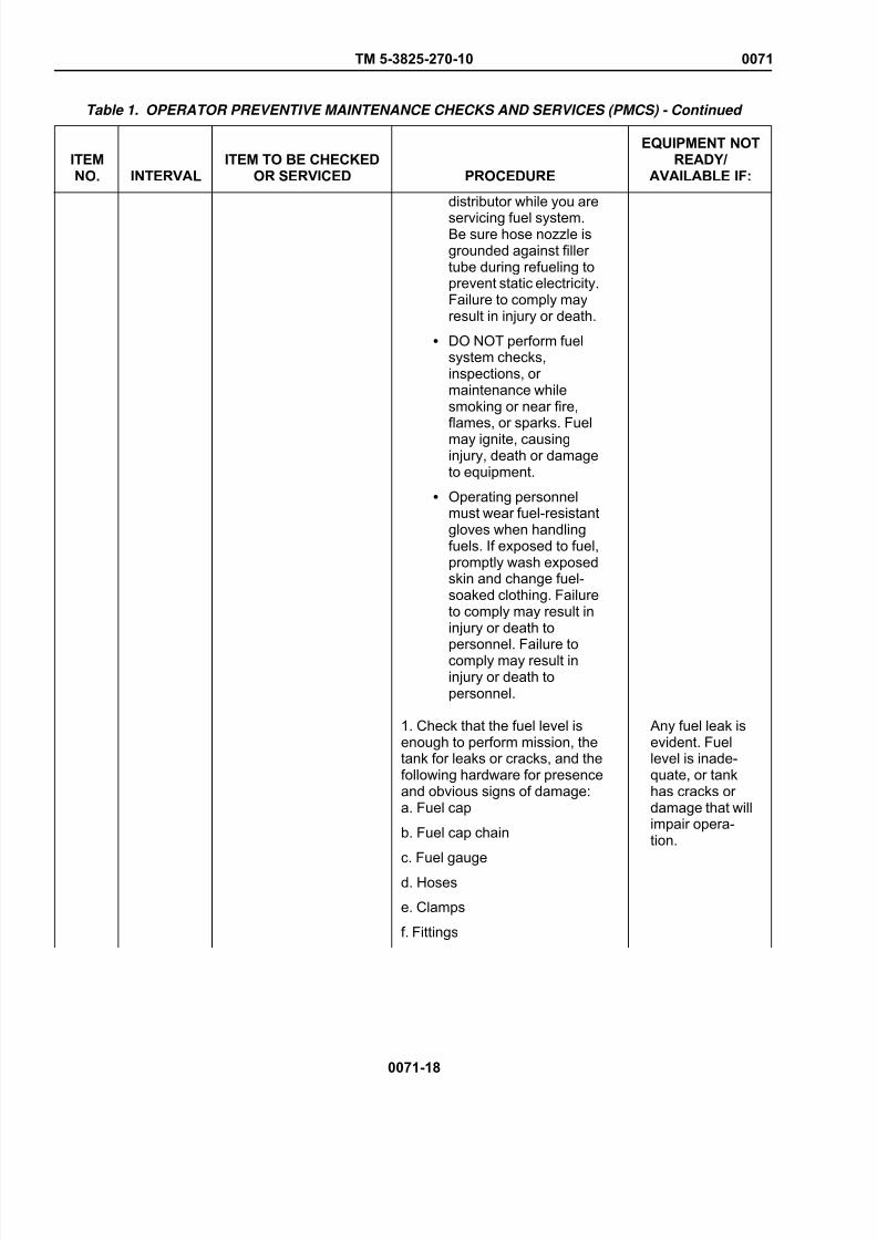
8/6/2019 TM 5-3825-270-10 ENGINEER MISSION MODULE WATER DISTRIBUTION
http://slidepdf.com/reader/full/tm-5-3825-270-10-engineer-mission-module-water-distribution 342/483
Table 1. OPERATOR PREVENTIVE MAINTENANCE CHECKS AND SERVICES (PMCS) - Continued
ITEMNO. INTERVAL
ITEM TO BE CHECKEDOR SERVICED PROCEDURE
EQUIPMENT NOTREADY/
AVAILABLE IF:
distributor while you are
servicing fuel system.Be sure hose nozzle isgrounded against filler tube during refueling toprevent static electricity.Failure to comply mayresult in injury or death.
• DO NOT perform fuelsystem checks,inspections, or maintenance whilesmoking or near fire,flames, or sparks. Fuel
may ignite, causinginjury, death or damageto equipment.
• Operating personnelmust wear fuel-resistantgloves when handlingfuels. If exposed to fuel,promptly wash exposedskin and change fuel-soaked clothing. Failureto comply may result ininjury or death topersonnel. Failure tocomply may result ininjury or death topersonnel.
1. Check that the fuel level isenough to perform mission, thetank for leaks or cracks, and thefollowing hardware for presenceand obvious signs of damage:a. Fuel cap
b. Fuel cap chain
c. Fuel gauge
d. Hoses
e. Clamps
f. Fittings
Any fuel leak isevident. Fuellevel is inade-quate, or tankhas cracks or damage that willimpair opera-tion.
TM 5-3825-270-10 0071
0071-18

8/6/2019 TM 5-3825-270-10 ENGINEER MISSION MODULE WATER DISTRIBUTION
http://slidepdf.com/reader/full/tm-5-3825-270-10-engineer-mission-module-water-distribution 343/483
Table 1. OPERATOR PREVENTIVE MAINTENANCE CHECKS AND SERVICES (PMCS) - Continued
ITEMNO. INTERVAL
ITEM TO BE CHECKEDOR SERVICED PROCEDURE
EQUIPMENT NOTREADY/
AVAILABLE IF:
FUEL TANK
FITTING CLAMPS HOSE
FUEL CAP
FUEL CAP
CHAIN
FUEL GAUGE
Figure 17. Fuel Tank.
18 Before UPIK Interface Kit 1. Check UPIK and the followinghardware for presence and obvioussigns of damage:a. Cap
b. Air hose cap
c. Cap chain
d. Pins
e. Cable seal
UPIK interfacekit has damagethat will impair operation.
TM 5-3825-270-10 0071
0071-19

8/6/2019 TM 5-3825-270-10 ENGINEER MISSION MODULE WATER DISTRIBUTION
http://slidepdf.com/reader/full/tm-5-3825-270-10-engineer-mission-module-water-distribution 344/483
Table 1. OPERATOR PREVENTIVE MAINTENANCE CHECKS AND SERVICES (PMCS) - Continued
ITEMNO. INTERVAL
ITEM TO BE CHECKEDOR SERVICED PROCEDURE
EQUIPMENT NOTREADY/
AVAILABLE IF:
CAP
AIR
HOSE CAP
CAP
CHAIN
PINS
CABLE
SEAL
Figure 18.
UPIK Interface Kit.
19 Before Stowage Box 1. Check that two stowage boxlatches and door operate correctly.
Stowage boxdoor will notlatch or hasdamage that willimpair opera-tion.
TM 5-3825-270-10 0071
0071-20
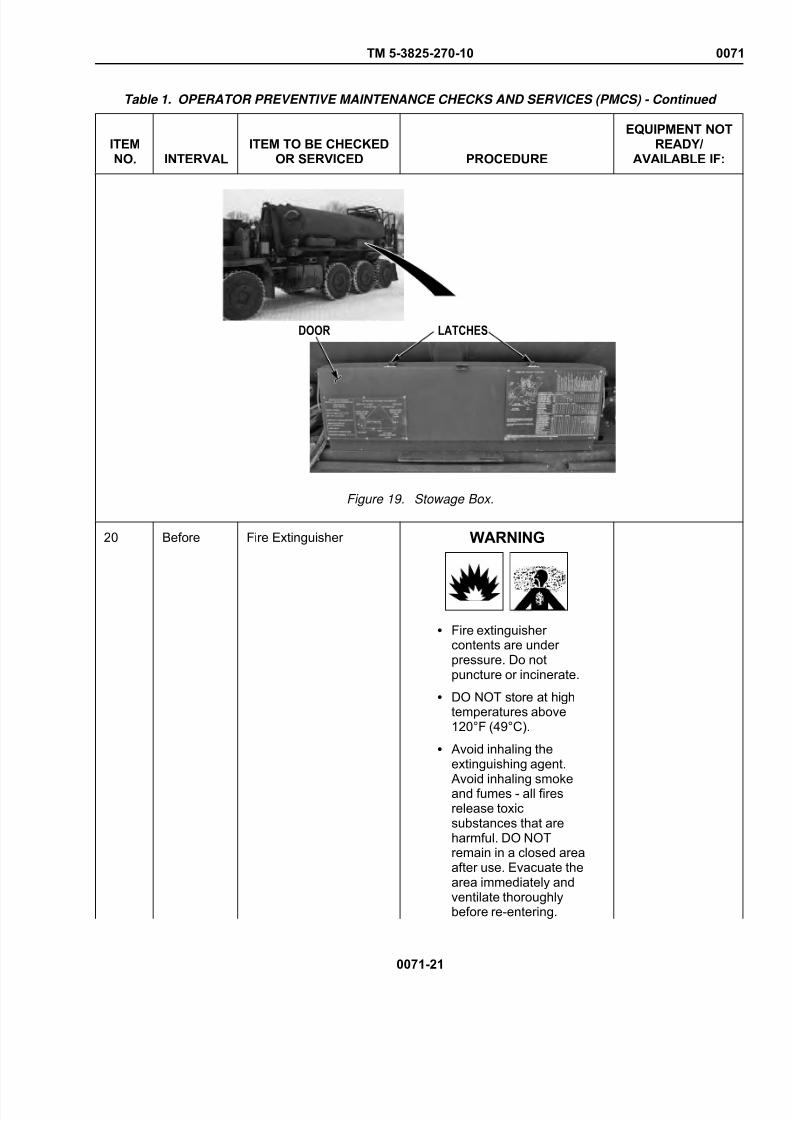
8/6/2019 TM 5-3825-270-10 ENGINEER MISSION MODULE WATER DISTRIBUTION
http://slidepdf.com/reader/full/tm-5-3825-270-10-engineer-mission-module-water-distribution 345/483
Table 1. OPERATOR PREVENTIVE MAINTENANCE CHECKS AND SERVICES (PMCS) - Continued
ITEMNO. INTERVAL
ITEM TO BE CHECKEDOR SERVICED PROCEDURE
EQUIPMENT NOTREADY/
AVAILABLE IF:
DOOR LATCHES
Figure 19. Stowage Box.
20 Before Fire Extinguisher WARNING
• Fire extinguisher
contents are under pressure. Do notpuncture or incinerate.
• DO NOT store at hightemperatures above120°F (49°C).
• Avoid inhaling theextinguishing agent.
Avoid inhaling smokeand fumes - all firesrelease toxicsubstances that areharmful. DO NOTremain in a closed areaafter use. Evacuate thearea immediately andventilate thoroughlybefore re-entering.
TM 5-3825-270-10 0071
0071-21

8/6/2019 TM 5-3825-270-10 ENGINEER MISSION MODULE WATER DISTRIBUTION
http://slidepdf.com/reader/full/tm-5-3825-270-10-engineer-mission-module-water-distribution 346/483
Table 1. OPERATOR PREVENTIVE MAINTENANCE CHECKS AND SERVICES (PMCS) - Continued
ITEMNO. INTERVAL
ITEM TO BE CHECKEDOR SERVICED PROCEDURE
EQUIPMENT NOTREADY/
AVAILABLE IF:
• Although extinguishing
agents are non-toxicwhen properly used,contact with them maycause irritation to eyes,nose, and throat andother allergicsymptoms.
• Failure to comply withthe above warningscould result in injury or death to personnel or damage to equipment.
1. Check that fire extinguisher ispresent, and has the following:a. Proper pressure
b. Proper seal condition
c. Proper expiration date
Fire extinguish-er is missing or damaged, pres-sure gauge nee-dle is in the redarea, seal isbroken, or ex-pired.
TM 5-3825-270-10 0071
0071-22
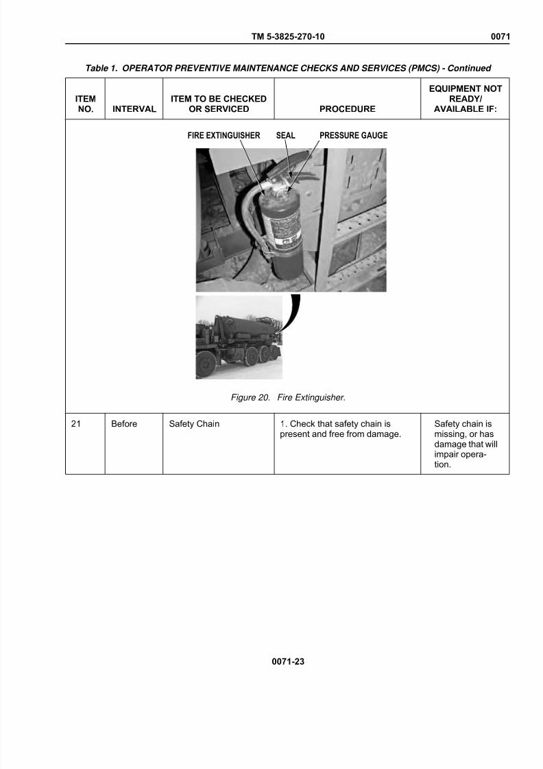
8/6/2019 TM 5-3825-270-10 ENGINEER MISSION MODULE WATER DISTRIBUTION
http://slidepdf.com/reader/full/tm-5-3825-270-10-engineer-mission-module-water-distribution 347/483
Table 1. OPERATOR PREVENTIVE MAINTENANCE CHECKS AND SERVICES (PMCS) - Continued
ITEMNO. INTERVAL
ITEM TO BE CHECKEDOR SERVICED PROCEDURE
EQUIPMENT NOTREADY/
AVAILABLE IF:
FIRE EXTINGUISHER SEAL PRESSURE GAUGE
Figure 20. Fire Extinguisher.
21 Before Safety Chain 1. Check that safety chain ispresent and free from damage.
Safety chain ismissing, or hasdamage that willimpair opera-tion.
TM 5-3825-270-10 0071
0071-23

8/6/2019 TM 5-3825-270-10 ENGINEER MISSION MODULE WATER DISTRIBUTION
http://slidepdf.com/reader/full/tm-5-3825-270-10-engineer-mission-module-water-distribution 348/483
Table 1. OPERATOR PREVENTIVE MAINTENANCE CHECKS AND SERVICES (PMCS) - Continued
ITEMNO. INTERVAL
ITEM TO BE CHECKEDOR SERVICED PROCEDURE
EQUIPMENT NOTREADY/
AVAILABLE IF:
SAFETY CHAIN
Figure 21. Safety Chain.
22 Before Folding Handrail 1. Check that folding handrail is freefrom obvious signs of damage.Check that the following hardwareis present:a. Retaining pins
b. Cables
Handrail or re-taining pinshave damagethat will impair operation.
TM 5-3825-270-10 0071
0071-24

8/6/2019 TM 5-3825-270-10 ENGINEER MISSION MODULE WATER DISTRIBUTION
http://slidepdf.com/reader/full/tm-5-3825-270-10-engineer-mission-module-water-distribution 349/483
Table 1. OPERATOR PREVENTIVE MAINTENANCE CHECKS AND SERVICES (PMCS) - Continued
ITEMNO. INTERVAL
ITEM TO BE CHECKEDOR SERVICED PROCEDURE
EQUIPMENT NOTREADY/
AVAILABLE IF:
RETAINING PIN FOLDING HANDRAIL
CABLE
Figure 22. Folding Handrail.
23 Before Control Box 1. Check control box, and thefollowing for presence and obvioussigns of damage:a. Cover
b. Rubber T-handle
Control box hasdamage that willimpair opera-tion.
TM 5-3825-270-10 0071
0071-25
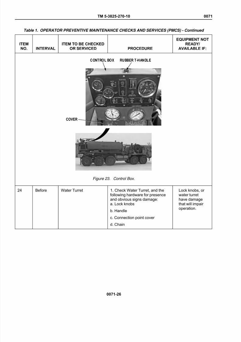
8/6/2019 TM 5-3825-270-10 ENGINEER MISSION MODULE WATER DISTRIBUTION
http://slidepdf.com/reader/full/tm-5-3825-270-10-engineer-mission-module-water-distribution 350/483
Table 1. OPERATOR PREVENTIVE MAINTENANCE CHECKS AND SERVICES (PMCS) - Continued
ITEMNO. INTERVAL
ITEM TO BE CHECKEDOR SERVICED PROCEDURE
EQUIPMENT NOTREADY/
AVAILABLE IF:
CONTROL BOX RUBBER T-HANDLE
COVER
Figure 23. Control Box.
24 Before Water Turret 1. Check Water Turret, and thefollowing hardware for presenceand obvious signs damage:a. Lock knobs
b. Handle
c. Connection point cover
d. Chain
Lock knobs, or water turrethave damagethat will impair operation.
TM 5-3825-270-10 0071
0071-26

8/6/2019 TM 5-3825-270-10 ENGINEER MISSION MODULE WATER DISTRIBUTION
http://slidepdf.com/reader/full/tm-5-3825-270-10-engineer-mission-module-water-distribution 351/483
Table 1. OPERATOR PREVENTIVE MAINTENANCE CHECKS AND SERVICES (PMCS) - Continued
ITEMNO. INTERVAL
ITEM TO BE CHECKEDOR SERVICED PROCEDURE
EQUIPMENT NOTREADY/
AVAILABLE IF:
WATER TURRETCONNECTIONPOINT COVER
CHAIN
HANDLE
LOCK
KNOB
Figure 24.
Water Turret.
25 Before Manhole Cover 1. Check that manhole cover isclosed and secured.
Manhole will notsecure.
TM 5-3825-270-10 0071
0071-27

8/6/2019 TM 5-3825-270-10 ENGINEER MISSION MODULE WATER DISTRIBUTION
http://slidepdf.com/reader/full/tm-5-3825-270-10-engineer-mission-module-water-distribution 352/483
Table 1. OPERATOR PREVENTIVE MAINTENANCE CHECKS AND SERVICES (PMCS) - Continued
ITEMNO. INTERVAL
ITEM TO BE CHECKEDOR SERVICED PROCEDURE
EQUIPMENT NOTREADY/
AVAILABLE IF:
MANHOLE COVER
Figure 25. Manhole Cover.
26 Before Hose Reel 1. Check hose reel and thefollowing for presence and obvioussigns of damage:a. Hose
b. Crank handle
c. Retaining pin
Hose reel, or hose has dam-age that will im-pair operation.Crank handle ismissing or hasdamage that willimpair opera-tion.
TM 5-3825-270-10 0071
0071-28

8/6/2019 TM 5-3825-270-10 ENGINEER MISSION MODULE WATER DISTRIBUTION
http://slidepdf.com/reader/full/tm-5-3825-270-10-engineer-mission-module-water-distribution 353/483
Table 1. OPERATOR PREVENTIVE MAINTENANCE CHECKS AND SERVICES (PMCS) - Continued
ITEMNO. INTERVAL
ITEM TO BE CHECKEDOR SERVICED PROCEDURE
EQUIPMENT NOTREADY/
AVAILABLE IF:
CRANK
HANDLE
RETAINING
PIN
HOSEHOSE
REEL
Figure 26. Hose Reel.
27 Before Sprinkler 1. Check sprinklers for obvioussigns of damage.
Sprinkler(s)have damagethat will impair operation.
TM 5-3825-270-10 0071
0071-29

8/6/2019 TM 5-3825-270-10 ENGINEER MISSION MODULE WATER DISTRIBUTION
http://slidepdf.com/reader/full/tm-5-3825-270-10-engineer-mission-module-water-distribution 354/483
Table 1. OPERATOR PREVENTIVE MAINTENANCE CHECKS AND SERVICES (PMCS) - Continued
ITEMNO. INTERVAL
ITEM TO BE CHECKEDOR SERVICED PROCEDURE
EQUIPMENT NOTREADY/
AVAILABLE IF:
SPRINKLERS
Figure 27. Sprinklers.
28 Before Air Oiler 1. Check air oiler for obvious signsof damage, and visually check oillevel through site glass.
Class III leak isevident. Oil lev-el is below fullline, or air oiler has damagethat will impair operation.
TM 5-3825-270-10 0071
0071-30

8/6/2019 TM 5-3825-270-10 ENGINEER MISSION MODULE WATER DISTRIBUTION
http://slidepdf.com/reader/full/tm-5-3825-270-10-engineer-mission-module-water-distribution 355/483
Table 1. OPERATOR PREVENTIVE MAINTENANCE CHECKS AND SERVICES (PMCS) - Continued
ITEMNO. INTERVAL
ITEM TO BE CHECKEDOR SERVICED PROCEDURE
EQUIPMENT NOTREADY/
AVAILABLE IF:
AIR
OILER
SIGHT
GLASS
Figure 28.
Air Oiler.
29 Before Air Actuators 1. Check Air actuators for obvioussigns of damage.
Class III leak isevident. Air ac-tuator(s) havedamage that willimpair opera-tion.
TM 5-3825-270-10 0071
0071-31
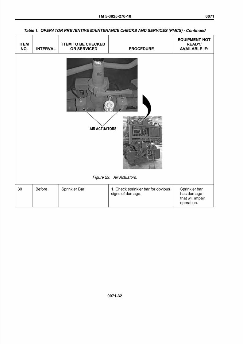
8/6/2019 TM 5-3825-270-10 ENGINEER MISSION MODULE WATER DISTRIBUTION
http://slidepdf.com/reader/full/tm-5-3825-270-10-engineer-mission-module-water-distribution 356/483
Table 1. OPERATOR PREVENTIVE MAINTENANCE CHECKS AND SERVICES (PMCS) - Continued
ITEMNO. INTERVAL
ITEM TO BE CHECKEDOR SERVICED PROCEDURE
EQUIPMENT NOTREADY/
AVAILABLE IF:
AIR ACTUATORS
Figure 29. Air Actuators.
30 Before Sprinkler Bar 1. Check sprinkler bar for obvioussigns of damage.
Sprinkler bar has damagethat will impair operation.
TM 5-3825-270-10 0071
0071-32

8/6/2019 TM 5-3825-270-10 ENGINEER MISSION MODULE WATER DISTRIBUTION
http://slidepdf.com/reader/full/tm-5-3825-270-10-engineer-mission-module-water-distribution 357/483
Table 1. OPERATOR PREVENTIVE MAINTENANCE CHECKS AND SERVICES (PMCS) - Continued
ITEMNO. INTERVAL
ITEM TO BE CHECKEDOR SERVICED PROCEDURE
EQUIPMENT NOTREADY/
AVAILABLE IF:
SPRINKLER
BAR
Figure 30. Sprinkler Bar.
31 Before Work Lights 1. Check work lights for proper operation, and the following for
presence and obvious signs of damage:a. Lenses
b. Housing
c. Wiring
Work lightshave damage
that will impair operation.
TM 5-3825-270-10 0071
0071-33

8/6/2019 TM 5-3825-270-10 ENGINEER MISSION MODULE WATER DISTRIBUTION
http://slidepdf.com/reader/full/tm-5-3825-270-10-engineer-mission-module-water-distribution 358/483
Table 1. OPERATOR PREVENTIVE MAINTENANCE CHECKS AND SERVICES (PMCS) - Continued
ITEMNO. INTERVAL
ITEM TO BE CHECKEDOR SERVICED PROCEDURE
EQUIPMENT NOTREADY/
AVAILABLE IF:
HOUSING
WIRING LENS
WORKLIGHT
Figure 31. Work Lights.
32 During Engine 1. Listen for the following duringengine operation (WP 0005):a. Unusual noise
b. Misfiring
c. Rough idling
Engine is idlingrough, misfiring,or making un-usual noise.
TM 5-3825-270-10 0071
0071-34

8/6/2019 TM 5-3825-270-10 ENGINEER MISSION MODULE WATER DISTRIBUTION
http://slidepdf.com/reader/full/tm-5-3825-270-10-engineer-mission-module-water-distribution 359/483
Table 1. OPERATOR PREVENTIVE MAINTENANCE CHECKS AND SERVICES (PMCS) - Continued
ITEMNO. INTERVAL
ITEM TO BE CHECKEDOR SERVICED PROCEDURE
EQUIPMENT NOTREADY/
AVAILABLE IF:
ENGINE
Figure 32. Engine.
33 During Exhaust WARNING
Engine components be-come hot during normal op-eration. Allow engine to coolcompletely prior to perform-ing this task. If necessary,
use insulated pads andgloves. Failure to complymay result in injury or deathto personnel.
1. Listen for the following duringengine operation (WP 0005):a. Leaks
Exhaust systemhas leak(s), or making unusualnoise.
TM 5-3825-270-10 0071
0071-35

8/6/2019 TM 5-3825-270-10 ENGINEER MISSION MODULE WATER DISTRIBUTION
http://slidepdf.com/reader/full/tm-5-3825-270-10-engineer-mission-module-water-distribution 360/483
Table 1. OPERATOR PREVENTIVE MAINTENANCE CHECKS AND SERVICES (PMCS) - Continued
ITEMNO. INTERVAL
ITEM TO BE CHECKEDOR SERVICED PROCEDURE
EQUIPMENT NOTREADY/
AVAILABLE IF:
b. Unusual noise
EXHAUST
SYSTEM
Figure 33. Exhaust System.
34 During Gauges and Indicators 1. Monitor the following gauges andindicators during operation for abnormal readings:a. Engine Oil pressure Gauge.Engine oil pressure gauge shouldread 7 psi (48 kPa) at normal idle,and 21 psi (145 kPa) duringspraying operations. If gauge goesbelow 7 psi (48 kPa) at normal idle,or below 21 psi (145 kPa) duringspraying operations, notify FieldMaintenance.
b. Engine Temperature Gauge.Engine temperature gauge shouldread between 170 - 190° F (77-88°C). If gauge stays below 160° F or goes above 220° F (104° C) notifyField Maintenance.
Any gauge or in-dicator has ab-normal reading.
TM 5-3825-270-10 0071
0071-36
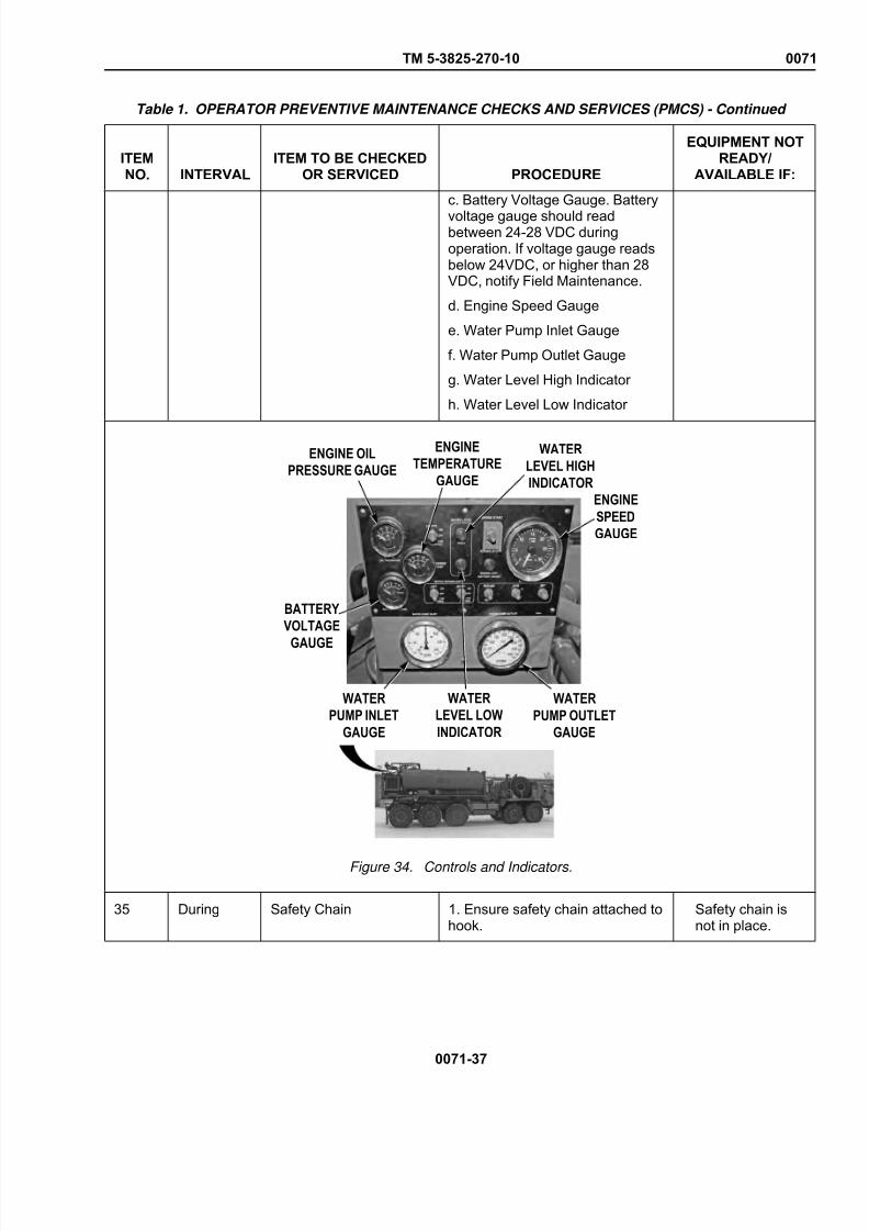
8/6/2019 TM 5-3825-270-10 ENGINEER MISSION MODULE WATER DISTRIBUTION
http://slidepdf.com/reader/full/tm-5-3825-270-10-engineer-mission-module-water-distribution 361/483
Table 1. OPERATOR PREVENTIVE MAINTENANCE CHECKS AND SERVICES (PMCS) - Continued
ITEMNO. INTERVAL
ITEM TO BE CHECKEDOR SERVICED PROCEDURE
EQUIPMENT NOTREADY/
AVAILABLE IF:
c. Battery Voltage Gauge. Battery
voltage gauge should readbetween 24-28 VDC duringoperation. If voltage gauge readsbelow 24VDC, or higher than 28VDC, notify Field Maintenance.
d. Engine Speed Gauge
e. Water Pump Inlet Gauge
f. Water Pump Outlet Gauge
g. Water Level High Indicator
h. Water Level Low Indicator
ENGINE OIL
PRESSURE GAUGE
ENGINE
TEMPERATURE
GAUGE
WATER
LEVEL HIGH
INDICATOR
WATER
LEVEL LOW
INDICATOR
ENGINE
SPEED
GAUGE
WATER
PUMP OUTLET
GAUGE
WATER
PUMP INLET
GAUGE
BATTERY
VOLTAGE
GAUGE
Figure 34. Controls and Indicators.
35 During Safety Chain 1. Ensure safety chain attached tohook.
Safety chain isnot in place.
TM 5-3825-270-10 0071
0071-37

8/6/2019 TM 5-3825-270-10 ENGINEER MISSION MODULE WATER DISTRIBUTION
http://slidepdf.com/reader/full/tm-5-3825-270-10-engineer-mission-module-water-distribution 362/483
Table 1. OPERATOR PREVENTIVE MAINTENANCE CHECKS AND SERVICES (PMCS) - Continued
ITEMNO. INTERVAL
ITEM TO BE CHECKEDOR SERVICED PROCEDURE
EQUIPMENT NOTREADY/
AVAILABLE IF:
SAFETY CHAIN
Figure 35. Safety Chain.
36 During Work Lights 1. Check work lights for proper operation.
Work lights areinoperative or have damagethat will impair operation.
TM 5-3825-270-10 0071
0071-38

8/6/2019 TM 5-3825-270-10 ENGINEER MISSION MODULE WATER DISTRIBUTION
http://slidepdf.com/reader/full/tm-5-3825-270-10-engineer-mission-module-water-distribution 363/483
Table 1. OPERATOR PREVENTIVE MAINTENANCE CHECKS AND SERVICES (PMCS) - Continued
ITEMNO. INTERVAL
ITEM TO BE CHECKEDOR SERVICED PROCEDURE
EQUIPMENT NOTREADY/
AVAILABLE IF:
WORKLIGHTS
Figure 36. Work Lights.
37 During Sprinkler 1. Check that material spraysproperly from sprinkler heads.
Sprinkler(s) areclogged.
TM 5-3825-270-10 0071
0071-39

8/6/2019 TM 5-3825-270-10 ENGINEER MISSION MODULE WATER DISTRIBUTION
http://slidepdf.com/reader/full/tm-5-3825-270-10-engineer-mission-module-water-distribution 364/483
Table 1. OPERATOR PREVENTIVE MAINTENANCE CHECKS AND SERVICES (PMCS) - Continued
ITEMNO. INTERVAL
ITEM TO BE CHECKEDOR SERVICED PROCEDURE
EQUIPMENT NOTREADY/
AVAILABLE IF:
SPRINKLERS
Figure 37. Sprinklers.
38 During Hose Reel 1. Check that hose reel operatesproperly, and that hose is free of leaks and obvious signs of damage.
Class III leak isevident. Hose or reel has dam-age that will im-pair operation.
TM 5-3825-270-10 0071
0071-40
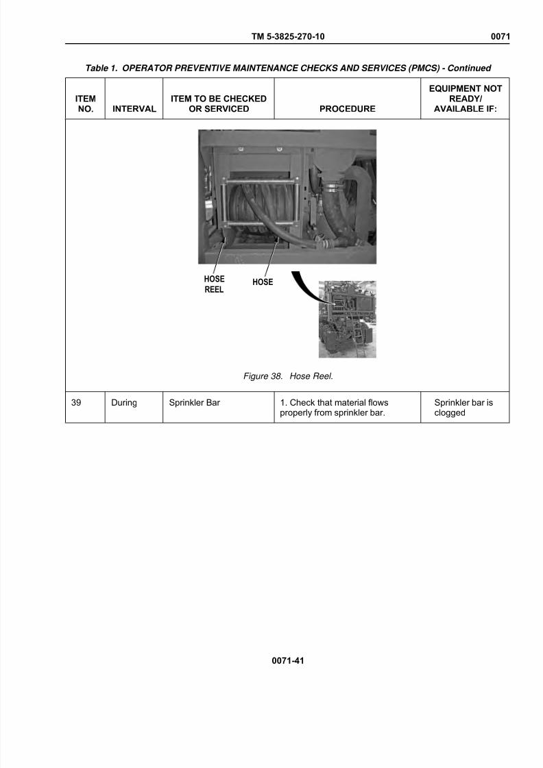
8/6/2019 TM 5-3825-270-10 ENGINEER MISSION MODULE WATER DISTRIBUTION
http://slidepdf.com/reader/full/tm-5-3825-270-10-engineer-mission-module-water-distribution 365/483
Table 1. OPERATOR PREVENTIVE MAINTENANCE CHECKS AND SERVICES (PMCS) - Continued
ITEMNO. INTERVAL
ITEM TO BE CHECKEDOR SERVICED PROCEDURE
EQUIPMENT NOTREADY/
AVAILABLE IF:
HOSEHOSE
REEL
Figure 38. Hose Reel.
39 During Sprinkler Bar 1. Check that material flowsproperly from sprinkler bar.
Sprinkler bar isclogged
TM 5-3825-270-10 0071
0071-41

8/6/2019 TM 5-3825-270-10 ENGINEER MISSION MODULE WATER DISTRIBUTION
http://slidepdf.com/reader/full/tm-5-3825-270-10-engineer-mission-module-water-distribution 366/483
Table 1. OPERATOR PREVENTIVE MAINTENANCE CHECKS AND SERVICES (PMCS) - Continued
ITEMNO. INTERVAL
ITEM TO BE CHECKEDOR SERVICED PROCEDURE
EQUIPMENT NOTREADY/
AVAILABLE IF:
SPRINKLER
BAR
Figure 39. Sprinkler Bar.
40 After Engine 1. Remove rear engine accesscover (WP 0082). Check for
evidence of leakage of the followingfluids on, or under water distributor:a. Oil
b. Antifreeze
c. Fuel
Class III or anyfuel leak is evi-
dent.
TM 5-3825-270-10 0071
0071-42

8/6/2019 TM 5-3825-270-10 ENGINEER MISSION MODULE WATER DISTRIBUTION
http://slidepdf.com/reader/full/tm-5-3825-270-10-engineer-mission-module-water-distribution 367/483
Table 1. OPERATOR PREVENTIVE MAINTENANCE CHECKS AND SERVICES (PMCS) - Continued
ITEMNO. INTERVAL
ITEM TO BE CHECKEDOR SERVICED PROCEDURE
EQUIPMENT NOTREADY/
AVAILABLE IF:
ENGINE
FUEL
ANTIFREEZE
OIL
Figure 40. Engine.
41 After Air Filter RestrictionIndicator
1. Visually check air filter restrictionindicator (WP 0085).
Indicator isdamaged or in-dicates air filter needs serviced.
TM 5-3825-270-10 0071
0071-43

8/6/2019 TM 5-3825-270-10 ENGINEER MISSION MODULE WATER DISTRIBUTION
http://slidepdf.com/reader/full/tm-5-3825-270-10-engineer-mission-module-water-distribution 368/483
Table 1. OPERATOR PREVENTIVE MAINTENANCE CHECKS AND SERVICES (PMCS) - Continued
ITEMNO. INTERVAL
ITEM TO BE CHECKEDOR SERVICED PROCEDURE
EQUIPMENT NOTREADY/
AVAILABLE IF:
AIR FILTER
RESTRICTION INDICATOR
Figure 41. Air Filter Restriction Indicator.
42 After Engine Oil Level 1. Remove rear engine accesscover (WP 0082). Check thatengine oil level is between bottom,and top line on dipstick
Oil level is be-low bottom line,excessivelyover top line, or dipstick is miss-ing or damaged.
TM 5-3825-270-10 0071
0071-44

8/6/2019 TM 5-3825-270-10 ENGINEER MISSION MODULE WATER DISTRIBUTION
http://slidepdf.com/reader/full/tm-5-3825-270-10-engineer-mission-module-water-distribution 369/483
Table 1. OPERATOR PREVENTIVE MAINTENANCE CHECKS AND SERVICES (PMCS) - Continued
ITEMNO. INTERVAL
ITEM TO BE CHECKEDOR SERVICED PROCEDURE
EQUIPMENT NOTREADY/
AVAILABLE IF:
LOW LINE HIGH LINE
DIPSTICK
Figure 42. Engine Oil Level.
43 After Hoses and ConnectionPoint Covers
1. Check hoses for presence andthat they are properly stowed.
2. Check all connection pointcovers and the following hardwarefor presence and obvious signs of damage:a. Tethers
b. Seals
c. Adapter screens
Hoses are miss-ing or not prop-erly stowed.Adapter screens areclogged. Con-nection pointcover(s), seals,adapter screens, or
hardware ismissing or hasdamage that willimpair opera-tion.
TM 5-3825-270-10 0071
0071-45
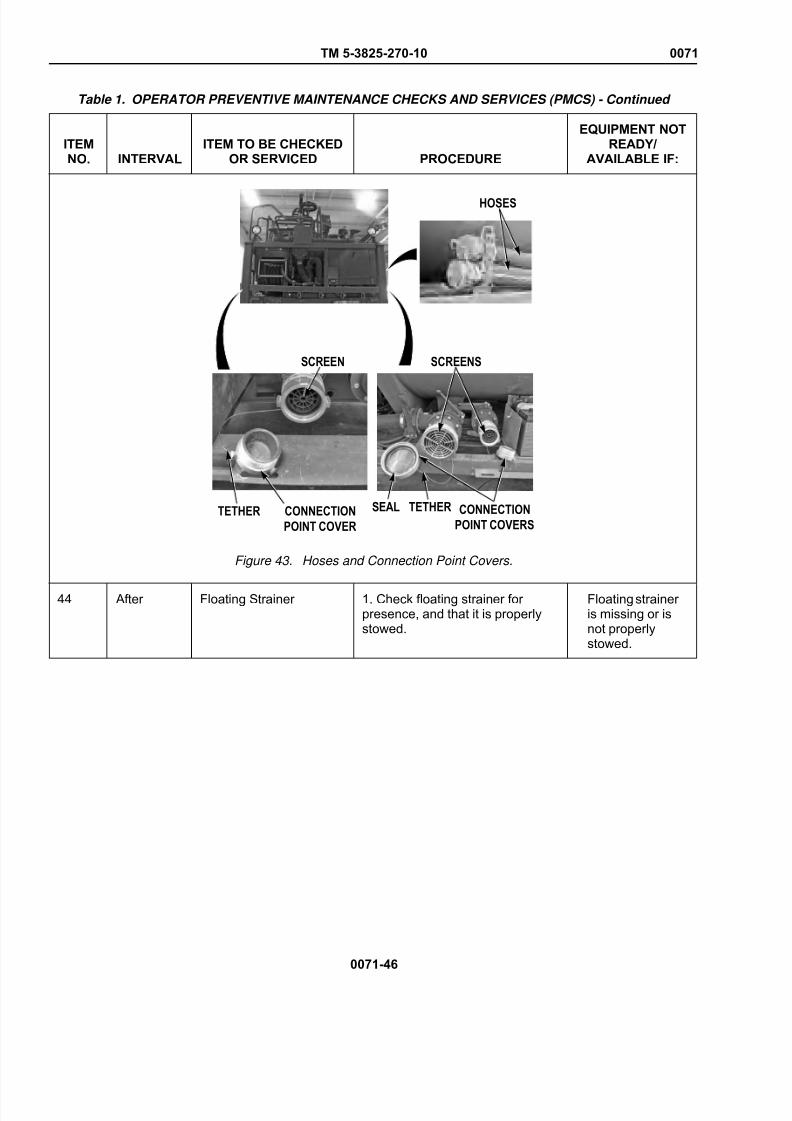
8/6/2019 TM 5-3825-270-10 ENGINEER MISSION MODULE WATER DISTRIBUTION
http://slidepdf.com/reader/full/tm-5-3825-270-10-engineer-mission-module-water-distribution 370/483
Table 1. OPERATOR PREVENTIVE MAINTENANCE CHECKS AND SERVICES (PMCS) - Continued
ITEMNO. INTERVAL
ITEM TO BE CHECKEDOR SERVICED PROCEDURE
EQUIPMENT NOTREADY/
AVAILABLE IF:
SCREEN SCREENS
HOSES
TETHER TETHERSEALCONNECTION
POINT COVER
CONNECTION
POINT COVERS
Figure 43. Hoses and Connection Point Covers.
44 After Floating Strainer 1. Check floating strainer for presence, and that it is properlystowed.
Floating strainer is missing or isnot properlystowed.
TM 5-3825-270-10 0071
0071-46
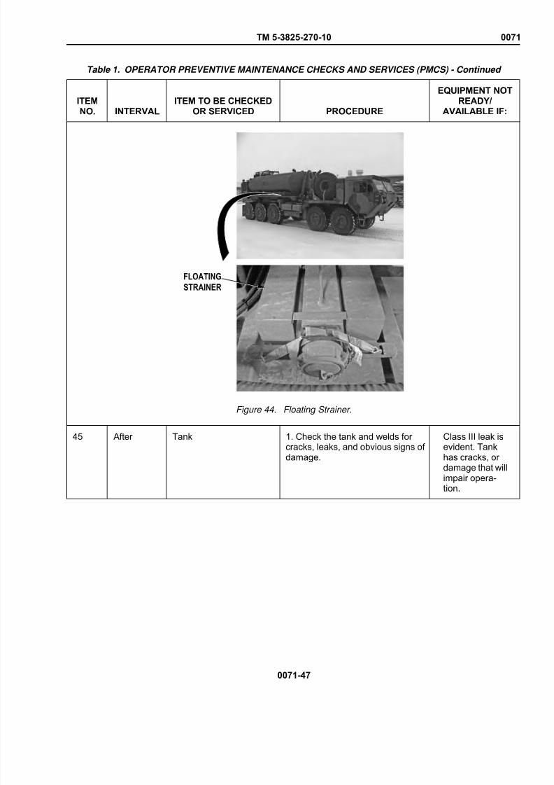
8/6/2019 TM 5-3825-270-10 ENGINEER MISSION MODULE WATER DISTRIBUTION
http://slidepdf.com/reader/full/tm-5-3825-270-10-engineer-mission-module-water-distribution 371/483
Table 1. OPERATOR PREVENTIVE MAINTENANCE CHECKS AND SERVICES (PMCS) - Continued
ITEMNO. INTERVAL
ITEM TO BE CHECKEDOR SERVICED PROCEDURE
EQUIPMENT NOTREADY/
AVAILABLE IF:
FLOATING
STRAINER
Figure 44.
Floating Strainer.
45 After Tank 1. Check the tank and welds for cracks, leaks, and obvious signs of damage.
Class III leak isevident. Tankhas cracks, or damage that willimpair opera-tion.
TM 5-3825-270-10 0071
0071-47
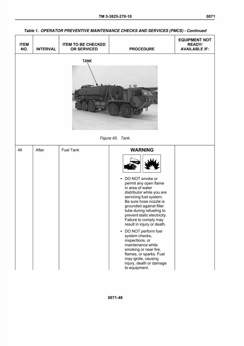
8/6/2019 TM 5-3825-270-10 ENGINEER MISSION MODULE WATER DISTRIBUTION
http://slidepdf.com/reader/full/tm-5-3825-270-10-engineer-mission-module-water-distribution 372/483
Table 1. OPERATOR PREVENTIVE MAINTENANCE CHECKS AND SERVICES (PMCS) - Continued
ITEMNO. INTERVAL
ITEM TO BE CHECKEDOR SERVICED PROCEDURE
EQUIPMENT NOTREADY/
AVAILABLE IF:
TANK
Figure 45. Tank.
46 After Fuel Tank WARNING
• DO NOT smoke or
permit any open flamein area of water distributor while you areservicing fuel system.Be sure hose nozzle isgrounded against filler tube during refueling toprevent static electricity.Failure to comply mayresult in injury or death.
• DO NOT perform fuelsystem checks,inspections, or maintenance whilesmoking or near fire,flames, or sparks. Fuelmay ignite, causinginjury, death or damageto equipment.
TM 5-3825-270-10 0071
0071-48

8/6/2019 TM 5-3825-270-10 ENGINEER MISSION MODULE WATER DISTRIBUTION
http://slidepdf.com/reader/full/tm-5-3825-270-10-engineer-mission-module-water-distribution 373/483
Table 1. OPERATOR PREVENTIVE MAINTENANCE CHECKS AND SERVICES (PMCS) - Continued
ITEMNO. INTERVAL
ITEM TO BE CHECKEDOR SERVICED PROCEDURE
EQUIPMENT NOTREADY/
AVAILABLE IF:
• Operating personnel
must wear fuel-resistantgloves when handlingfuels. If exposed to fuel,promptly wash exposedskin and change fuel-soaked clothing. Failureto comply may result ininjury or death topersonnel. Failure tocomply may result ininjury or death topersonnel.
1. Check fuel tank for leaks or cracks, and the following hardwarefor presence and obvious signs of damage:a. Fuel cap
b. Fuel cap chain
c. Fuel gauge
d. Hoses
e. Clamps
f. Fittings
Any fuel leak isevident. Fueltank or hard-ware has dam-age that will im-pair operation.
TM 5-3825-270-10 0071
0071-49

8/6/2019 TM 5-3825-270-10 ENGINEER MISSION MODULE WATER DISTRIBUTION
http://slidepdf.com/reader/full/tm-5-3825-270-10-engineer-mission-module-water-distribution 374/483
Table 1. OPERATOR PREVENTIVE MAINTENANCE CHECKS AND SERVICES (PMCS) - Continued
ITEMNO. INTERVAL
ITEM TO BE CHECKEDOR SERVICED PROCEDURE
EQUIPMENT NOTREADY/
AVAILABLE IF:
FUEL TANK
FITTING CLAMPS HOSE
FUEL CAP
FUEL CAP
CHAIN
FUEL GAUGE
Figure 46. Fuel Tank.
47 After UPIK Interface Kit 1. Check the UPIK and the followinghardware for presence, andobvious signs of damage:a. Cap
b. Air hose cap
c. Chain
d. Pins
e. Cable seal
UPIK interfacekit has damagethat will impair operation.
TM 5-3825-270-10 0071
0071-50

8/6/2019 TM 5-3825-270-10 ENGINEER MISSION MODULE WATER DISTRIBUTION
http://slidepdf.com/reader/full/tm-5-3825-270-10-engineer-mission-module-water-distribution 375/483
Table 1. OPERATOR PREVENTIVE MAINTENANCE CHECKS AND SERVICES (PMCS) - Continued
ITEMNO. INTERVAL
ITEM TO BE CHECKEDOR SERVICED PROCEDURE
EQUIPMENT NOTREADY/
AVAILABLE IF:
CAP
AIR
HOSE CAP
CAP
CHAIN
PINS
CABLE
SEAL
Figure 47.
UPIK Interface Kit.
48 After Stowage Box 1. Check that the stowage box isclosed and latched.
Stowage boxwill not closeand latch prop-erly.
TM 5-3825-270-10 0071
0071-51

8/6/2019 TM 5-3825-270-10 ENGINEER MISSION MODULE WATER DISTRIBUTION
http://slidepdf.com/reader/full/tm-5-3825-270-10-engineer-mission-module-water-distribution 376/483
Table 1. OPERATOR PREVENTIVE MAINTENANCE CHECKS AND SERVICES (PMCS) - Continued
ITEMNO. INTERVAL
ITEM TO BE CHECKEDOR SERVICED PROCEDURE
EQUIPMENT NOTREADY/
AVAILABLE IF:
DOOR LATCHES
Figure 48. Stowage Box.
49 After Ladder WARNING
Keep hands and fingersclear of ladder rungs andsides when placing ladder inthe stowed position. Failureto comply may result in in-
jury or death to personnel.
1. Check that ladder for present,and that properly stowed.
Ladder is miss-ing or not prop-erly stowed.
TM 5-3825-270-10 0071
0071-52

8/6/2019 TM 5-3825-270-10 ENGINEER MISSION MODULE WATER DISTRIBUTION
http://slidepdf.com/reader/full/tm-5-3825-270-10-engineer-mission-module-water-distribution 377/483
Table 1. OPERATOR PREVENTIVE MAINTENANCE CHECKS AND SERVICES (PMCS) - Continued
ITEMNO. INTERVAL
ITEM TO BE CHECKEDOR SERVICED PROCEDURE
EQUIPMENT NOTREADY/
AVAILABLE IF:
LADDER
Figure 49. Ladder.
50 After Hose Reel 1. Check that hose is properlystowed, and the following for presence and obvious signs of damage:a. Hose
b. Crank handle
c. Retaining pins
Hose is notproperly stow-ed. Crank han-dle is missing,or has damagethat will impair operation. Hosereel or hose hasdamage that willimpair opera-tion.
TM 5-3825-270-10 0071
0071-53
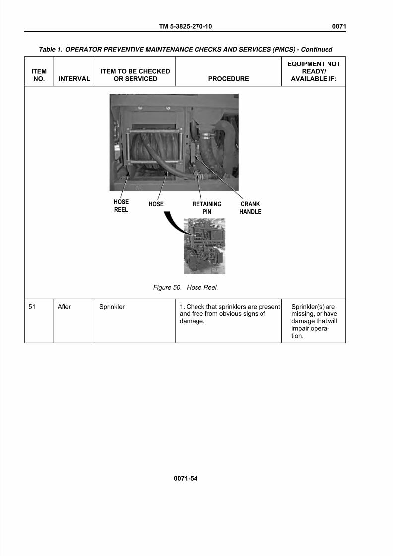
8/6/2019 TM 5-3825-270-10 ENGINEER MISSION MODULE WATER DISTRIBUTION
http://slidepdf.com/reader/full/tm-5-3825-270-10-engineer-mission-module-water-distribution 378/483
Table 1. OPERATOR PREVENTIVE MAINTENANCE CHECKS AND SERVICES (PMCS) - Continued
ITEMNO. INTERVAL
ITEM TO BE CHECKEDOR SERVICED PROCEDURE
EQUIPMENT NOTREADY/
AVAILABLE IF:
CRANK
HANDLE
RETAINING
PIN
HOSEHOSE
REEL
Figure 50. Hose Reel.
51 After Sprinkler 1. Check that sprinklers are presentand free from obvious signs of damage.
Sprinkler(s) aremissing, or havedamage that willimpair opera-tion.
TM 5-3825-270-10 0071
0071-54

8/6/2019 TM 5-3825-270-10 ENGINEER MISSION MODULE WATER DISTRIBUTION
http://slidepdf.com/reader/full/tm-5-3825-270-10-engineer-mission-module-water-distribution 379/483
Table 1. OPERATOR PREVENTIVE MAINTENANCE CHECKS AND SERVICES (PMCS) - Continued
ITEMNO. INTERVAL
ITEM TO BE CHECKEDOR SERVICED PROCEDURE
EQUIPMENT NOTREADY/
AVAILABLE IF:
SPRINKLERS
Figure 51. Sprinklers.
52 After Rollers 1. Check rollers for the following:a. Ensure that retaining pins andholding pins are free of corrosion.
b. Ensure that roller will rotate.
c. Ensure roll pins are notdamaged.
Neither roller functions cor-rectly or hasdamage that willimpair opera-tion.
TM 5-3825-270-10 0071
0071-55

8/6/2019 TM 5-3825-270-10 ENGINEER MISSION MODULE WATER DISTRIBUTION
http://slidepdf.com/reader/full/tm-5-3825-270-10-engineer-mission-module-water-distribution 380/483
Table 1. OPERATOR PREVENTIVE MAINTENANCE CHECKS AND SERVICES (PMCS) - Continued
ITEMNO. INTERVAL
ITEM TO BE CHECKEDOR SERVICED PROCEDURE
EQUIPMENT NOTREADY/
AVAILABLE IF:
RETAINING PINRING
HOLDING
PIN
REAR VIEW
VIEW FROM
UNDERNEATH
ROLLER
ROLLER
ROLL
PIN
Figure 52. Rollers.
53 After Sprinkler Bar 1. Check sprinkler bar for obvioussigns of damage.
Sprinkler bar has damagethat will impair operation.
TM 5-3825-270-10 0071
0071-56

8/6/2019 TM 5-3825-270-10 ENGINEER MISSION MODULE WATER DISTRIBUTION
http://slidepdf.com/reader/full/tm-5-3825-270-10-engineer-mission-module-water-distribution 381/483
Table 1. OPERATOR PREVENTIVE MAINTENANCE CHECKS AND SERVICES (PMCS) - Continued
ITEMNO. INTERVAL
ITEM TO BE CHECKEDOR SERVICED PROCEDURE
EQUIPMENT NOTREADY/
AVAILABLE IF:
SPRINKLER
BAR
Figure 53. Sprinkler Bar.
54 Weekly Exhaust System 1. Check the following exhaustsystem components for presence
and obvious signs of damage:a. Muffler
b. Tail pipe
c. Clamps
d. Brackets
Exhaust systemhas missing
hardware, or damage that willimpair opera-tion.
TM 5-3825-270-10 0071
0071-57
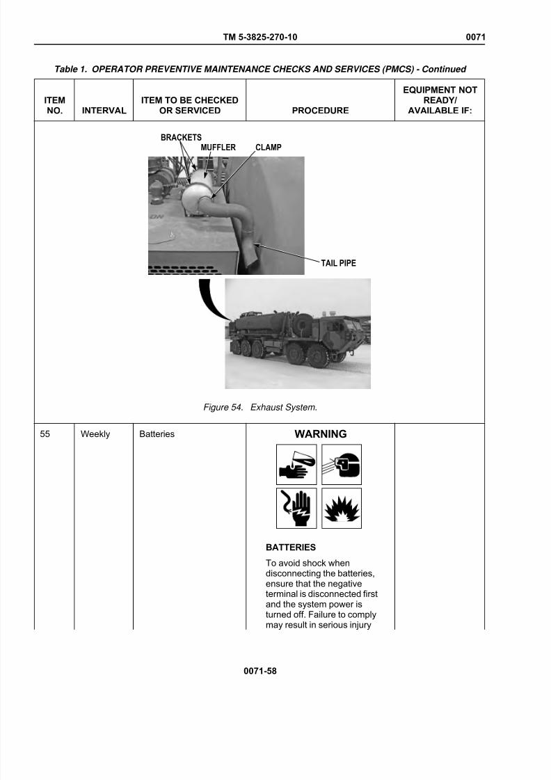
8/6/2019 TM 5-3825-270-10 ENGINEER MISSION MODULE WATER DISTRIBUTION
http://slidepdf.com/reader/full/tm-5-3825-270-10-engineer-mission-module-water-distribution 382/483
Table 1. OPERATOR PREVENTIVE MAINTENANCE CHECKS AND SERVICES (PMCS) - Continued
ITEMNO. INTERVAL
ITEM TO BE CHECKEDOR SERVICED PROCEDURE
EQUIPMENT NOTREADY/
AVAILABLE IF:
BRACKETSMUFFLER CLAMP
TAIL PIPE
Figure 54. Exhaust System.
55 Weekly Batteries WARNING
BATTERIES
To avoid shock whendisconnecting the batteries,ensure that the negativeterminal is disconnected firstand the system power isturned off. Failure to complymay result in serious injury
TM 5-3825-270-10 0071
0071-58

8/6/2019 TM 5-3825-270-10 ENGINEER MISSION MODULE WATER DISTRIBUTION
http://slidepdf.com/reader/full/tm-5-3825-270-10-engineer-mission-module-water-distribution 383/483
Table 1. OPERATOR PREVENTIVE MAINTENANCE CHECKS AND SERVICES (PMCS) - Continued
ITEMNO. INTERVAL
ITEM TO BE CHECKEDOR SERVICED PROCEDURE
EQUIPMENT NOTREADY/
AVAILABLE IF:
or death to personnel and/or
damage to equipment.
1. Remove battery box cover (WP 0081). Check the followingbattery components for presenceand obvious signs of damage:a. Batteries
b. Battery cables
c. Battery hold down
d. Battery box
Batteries, bat-tery cables, bat-tery box, or holddown is miss-ing, or has dam-age that will im-pair operation.
BATTERY BOX
BATTERIES
BATTERY CABLEBATTERY HOLD DOWN
Figure 55. Batteries.
TM 5-3825-270-10 0071
0071-59

8/6/2019 TM 5-3825-270-10 ENGINEER MISSION MODULE WATER DISTRIBUTION
http://slidepdf.com/reader/full/tm-5-3825-270-10-engineer-mission-module-water-distribution 384/483
Table 1. OPERATOR PREVENTIVE MAINTENANCE CHECKS AND SERVICES (PMCS) - Continued
ITEMNO. INTERVAL
ITEM TO BE CHECKEDOR SERVICED PROCEDURE
EQUIPMENT NOTREADY/
AVAILABLE IF:
56 Weekly Fuel TankWARNING
• DO NOT smoke or
permit any open flamein area of water distributor while you areservicing fuel system.Be sure hose nozzle isgrounded against filler tube during refueling toprevent static electricity.Failure to comply mayresult in injury or death.
• DO NOT perform fuelsystem checks,inspections, or maintenance whilesmoking or near fire,flames, or sparks. Fuelmay ignite, causinginjury, death or damageto equipment.
• Operating personnelmust wear fuel-resistantgloves when handlingfuels. If exposed to fuel,promptly wash exposedskin and change fuel-soaked clothing. Failureto comply may result ininjury or death topersonnel. Failure tocomply may result ininjury or death topersonnel.
1. Check fuel tank for leaks, cracks,and obvious signs of damage.
Any fuel leak isevident. Fueltank has dam-age that will im-pair operation.
TM 5-3825-270-10 0071
0071-60
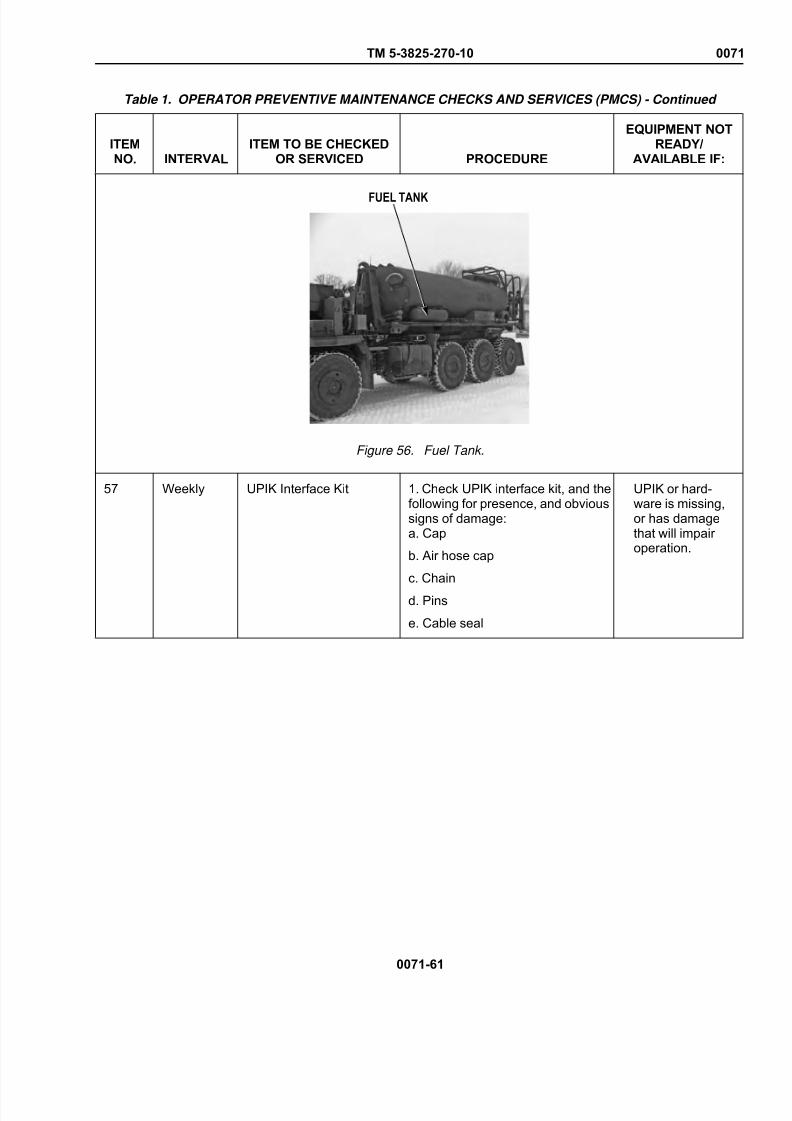
8/6/2019 TM 5-3825-270-10 ENGINEER MISSION MODULE WATER DISTRIBUTION
http://slidepdf.com/reader/full/tm-5-3825-270-10-engineer-mission-module-water-distribution 385/483
Table 1. OPERATOR PREVENTIVE MAINTENANCE CHECKS AND SERVICES (PMCS) - Continued
ITEMNO. INTERVAL
ITEM TO BE CHECKEDOR SERVICED PROCEDURE
EQUIPMENT NOTREADY/
AVAILABLE IF:
FUEL TANK
Figure 56. Fuel Tank.
57 Weekly UPIK Interface Kit 1. Check UPIK interface kit, and thefollowing for presence, and obvioussigns of damage:a. Cap
b. Air hose cap
c. Chain
d. Pins
e. Cable seal
UPIK or hard-ware is missing,or has damagethat will impair operation.
TM 5-3825-270-10 0071
0071-61
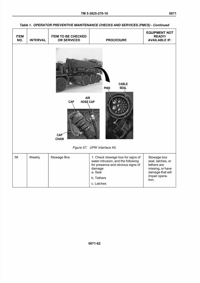
8/6/2019 TM 5-3825-270-10 ENGINEER MISSION MODULE WATER DISTRIBUTION
http://slidepdf.com/reader/full/tm-5-3825-270-10-engineer-mission-module-water-distribution 386/483
Table 1. OPERATOR PREVENTIVE MAINTENANCE CHECKS AND SERVICES (PMCS) - Continued
ITEMNO. INTERVAL
ITEM TO BE CHECKEDOR SERVICED PROCEDURE
EQUIPMENT NOTREADY/
AVAILABLE IF:
CAP
AIR
HOSE CAP
CAP
CHAIN
PINS
CABLE
SEAL
Figure 57.
UPIK Interface Kit.
58 Weekly Stowage Box 1. Check stowage box for signs of water intrusion, and the followingfor presence and obvious signs of damage:a. Seal
b. Tethers
c. Latches
Stowage boxseal, latches, or tethers aremissing, or havedamage that willimpair opera-tion.
TM 5-3825-270-10 0071
0071-62
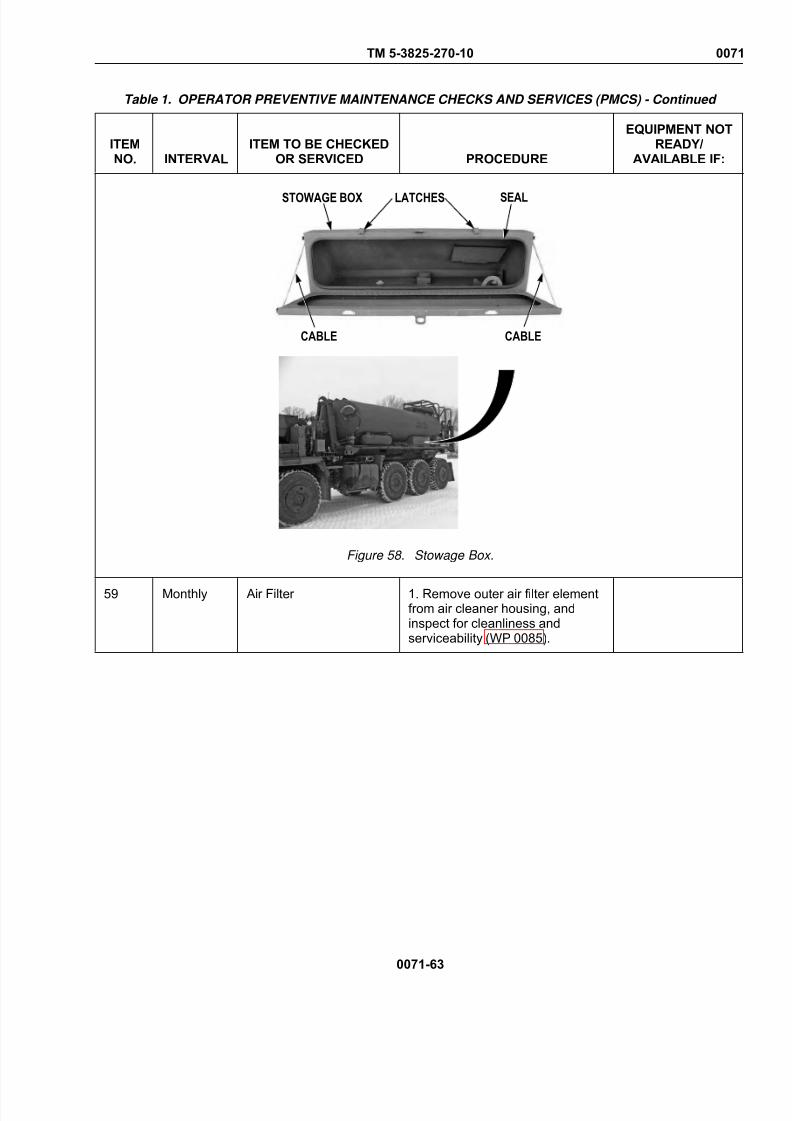
8/6/2019 TM 5-3825-270-10 ENGINEER MISSION MODULE WATER DISTRIBUTION
http://slidepdf.com/reader/full/tm-5-3825-270-10-engineer-mission-module-water-distribution 387/483
Table 1. OPERATOR PREVENTIVE MAINTENANCE CHECKS AND SERVICES (PMCS) - Continued
ITEMNO. INTERVAL
ITEM TO BE CHECKEDOR SERVICED PROCEDURE
EQUIPMENT NOTREADY/
AVAILABLE IF:
STOWAGE BOX
CABLECABLE
LATCHES SEAL
Figure 58. Stowage Box.
59 Monthly Air Filter 1. Remove outer air filter elementfrom air cleaner housing, andinspect for cleanliness andserviceability (WP 0085).
TM 5-3825-270-10 0071
0071-63

8/6/2019 TM 5-3825-270-10 ENGINEER MISSION MODULE WATER DISTRIBUTION
http://slidepdf.com/reader/full/tm-5-3825-270-10-engineer-mission-module-water-distribution 388/483
Table 1. OPERATOR PREVENTIVE MAINTENANCE CHECKS AND SERVICES (PMCS) - Continued
ITEMNO. INTERVAL
ITEM TO BE CHECKEDOR SERVICED PROCEDURE
EQUIPMENT NOTREADY/
AVAILABLE IF:
AIR CLEANER
OUTER
AIR
FILTER
ELEMENT
Figure 59.
Air Filter.
60 Semi-Annual
Sheet Metal and Frame 1. Inspect sheet metal, and framefor the following conditions. If anyare found, refer to AR 750-59 Armycorrosion prevention and control:a. Corrosion
b. Surface color changes
c. Surface separation
d. Blistered paint
e. Rust through
f. Broken frame rails
g. Broken cross members
h. Cracked welds
i. Other signs of damage
Sheet metal or frame has dam-age that will im-pair operation.
TM 5-3825-270-10 0071
0071-64
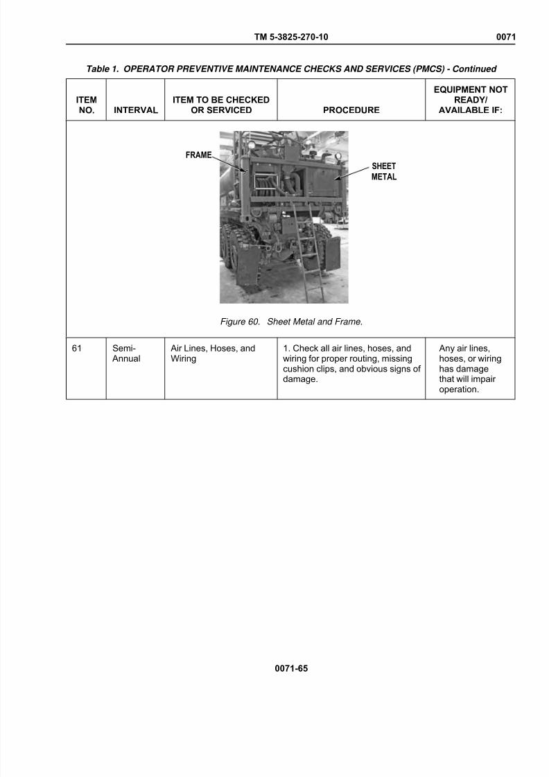
8/6/2019 TM 5-3825-270-10 ENGINEER MISSION MODULE WATER DISTRIBUTION
http://slidepdf.com/reader/full/tm-5-3825-270-10-engineer-mission-module-water-distribution 389/483
Table 1. OPERATOR PREVENTIVE MAINTENANCE CHECKS AND SERVICES (PMCS) - Continued
ITEMNO. INTERVAL
ITEM TO BE CHECKEDOR SERVICED PROCEDURE
EQUIPMENT NOTREADY/
AVAILABLE IF:
FRAME
SHEET
METAL
Figure 60. Sheet Metal and Frame.
61 Semi-Annual
Air Lines, Hoses, andWiring
1. Check all air lines, hoses, andwiring for proper routing, missingcushion clips, and obvious signs of damage.
Any air lines,hoses, or wiringhas damagethat will impair operation.
TM 5-3825-270-10 0071
0071-65

8/6/2019 TM 5-3825-270-10 ENGINEER MISSION MODULE WATER DISTRIBUTION
http://slidepdf.com/reader/full/tm-5-3825-270-10-engineer-mission-module-water-distribution 390/483
Table 1. OPERATOR PREVENTIVE MAINTENANCE CHECKS AND SERVICES (PMCS) - Continued
ITEMNO. INTERVAL
ITEM TO BE CHECKEDOR SERVICED PROCEDURE
EQUIPMENT NOTREADY/
AVAILABLE IF:
HOSES
CUSHION
CLIP
AIR LINES
WIRING
Figure 61. Air Lines, Hoses, and Wiring.
62 Semi-Annual
Valves and ConnectionPoint Covers
1. Check all valves for proper operation, and obvious signs of damage.
2. Check all connection pointcovers for proper seal condition andobvious signs of damage.
Any valve doesnot operateproperly, or hasdamage that willimpair opera-tion. Any con-nection pointcover or seal ismissing, or hasdamage that willimpair opera-tion.
TM 5-3825-270-10 0071
0071-66

8/6/2019 TM 5-3825-270-10 ENGINEER MISSION MODULE WATER DISTRIBUTION
http://slidepdf.com/reader/full/tm-5-3825-270-10-engineer-mission-module-water-distribution 391/483
Table 1. OPERATOR PREVENTIVE MAINTENANCE CHECKS AND SERVICES (PMCS) - Continued
ITEMNO. INTERVAL
ITEM TO BE CHECKEDOR SERVICED PROCEDURE
EQUIPMENT NOTREADY/
AVAILABLE IF:
VALVES
CONNECTION
POINT COVERS
CONNECTION
POINT COVER
SEAL
Figure 62. Valves and Connection Point Covers.
END OF TASK
END OF WORK PACKAGE
TM 5-3825-270-10 0071
0071-67/68 blank

8/6/2019 TM 5-3825-270-10 ENGINEER MISSION MODULE WATER DISTRIBUTION
http://slidepdf.com/reader/full/tm-5-3825-270-10-engineer-mission-module-water-distribution 392/483

8/6/2019 TM 5-3825-270-10 ENGINEER MISSION MODULE WATER DISTRIBUTION
http://slidepdf.com/reader/full/tm-5-3825-270-10-engineer-mission-module-water-distribution 393/483
CHAPTER 5
MAINTENANCE INSTRUCTIONS
TM 5-3825-270-10

8/6/2019 TM 5-3825-270-10 ENGINEER MISSION MODULE WATER DISTRIBUTION
http://slidepdf.com/reader/full/tm-5-3825-270-10-engineer-mission-module-water-distribution 394/483

8/6/2019 TM 5-3825-270-10 ENGINEER MISSION MODULE WATER DISTRIBUTION
http://slidepdf.com/reader/full/tm-5-3825-270-10-engineer-mission-module-water-distribution 395/483
OPERATOR MAINTENANCESERVICE UPON RECEIPT
INITIAL SETUP:
Not Applicable
UNPACKING AND DEPROCESSING
UNPACKING
Upon receipt of new equipment, the receiving organization must see if equipment has been properly prepared for service and is in good condition. Inspect all assemblies, subassemblies, and accessories to be sure they are inproper working order. Secure, clean, and correctly adjust and/or lubricate, as needed (see Field Level PreventiveMaintenance Checks and Services (PMCS) Tables and Operator's Preventive Maintenance Checks and Services
(PMCS) Tables (WP 0070)). Check all tools and equipment to be sure every item is there and in good condition anclean (WP 0087).
END OF TASK
UNPACKING
WARNING
SOLVENT CLEANING COMPOUND (DRYCLEANING SOLVENT)
• Solvent cleaning compound MIL-PRF-680 Type II and III may be irritating to the eyes andskin. Use protective gloves and goggles. Use in a well-ventilated area. Use respirator asneeded. Accidental ingestion can cause irritation of digestive tract and respiratory tract,may cause lung and central nervous system damage. Can be fatal if swallowed.Inhalation of high/massive concentrations can cause coma or be fatal. First aid for ingestion: do not induce vomiting. Seek immediate medical attention. First aid for skincontact: remove contaminated clothing. Wash skin thoroughly with soap and water. If symptoms persist, seek medical attention. First aid for eye contact: flush with water for 15 minutes or until irritation subsides. If symptoms persist, seek medical attention. Firstaid for inhalation: move to fresh air. If not breathing, provide artificial respiration. If symptoms persist, seek medical attention. Keep away from open flames and other
sources of ignition. Failure to comply may result in injury or death to personnel.
• The flashpoint for Type II solvent cleaning compound is 141 to 198°F (61 to 92°C), andType III is 200 to 241°F (93 to 116°C).
• Improper cleaning methods and use of unauthorized cleaning solvents may result in injuryto personnel and/or damage to equipment.
• Fire extinguishers should be placed nearby when using solvent cleaning compound.Failure to comply may result in injury or death to personnel.
TM 5-3825-270-10 0072
0072-1
8/6/2019 TM 5-3825-270-10 ENGINEER MISSION MODULE WATER DISTRIBUTION
http://slidepdf.com/reader/full/tm-5-3825-270-10-engineer-mission-module-water-distribution 396/483
UNPACKING - Continued
• Cloths or rags saturated with solvent cleaning compound must be disposed of IAWauthorized facilities' procedures. Failure to comply may result in injury to personnel.
• Eye shields must be worn when cleaning with a wire brush. Failure to comply may resultin injury to personnel.
• If personnel become dizzy while using cleaning solvent, immediately get fresh air andmedical help. If solvent contacts skin or clothes, flush with cold water. If solvent contactseyes, immediately flush eyes with water and get immediate medical attention. Failure tocomply may result in injury or death to personnel.
Remove any metal strapping, plywood, tapes, seals, wrapping or any other shipping and protective items. If anyparts are coated with lubricating oil, remove it using solvent cleaning compound. Read and follow all instructionscontained in DD Form 1397 (WP 0086), "Processing and Deprocessing Record of Shipping, Storage, and Issue of Trucks and Spare Engines". Inspect flatrack for damage incurred during shipping. If flatrack has been damaged,report the damage on SF 364 Supply Discrepancy Report. Check the equipment against the packing slip to ensureshipment is complete. Report all discrepancies in accordance with DA PAM 750-8 (WP 0086).
END OF TASK
SERVICING
Perform the Preventive Maintenance Checks and Services in PMCS. Schedule the next Preventive MaintenanceChecks and Services on DD Form 314 (WP 0086), Preventive Maintenance Schedule and Record. Report alldeficiencies on DA Form 2407 (WP 0086) if the deficiencies appear to involve unsatisfactory design.
END OF TASK
PACKING
Preservation and other protective measures taken in the preparation of material and accompanying tools andequipment for shipment must be sufficient to protect the material against deterioration and physical damage during
shipment. Use solvent cleaning compound to clean or wash grease or oil from all metal parts. All surfaces must beclean to ensure removal of corrosion, soil, grease, or residues. After cleaning, use cold water to rinse flatrack. Dryall parts thoroughly with a lint-free cloth. Spot paint all surfaces as necessary TB 43–0209 (WP 0086).
END OF TASK
SERVICE BEFORE OPERATION
GENERAL
1. Refer to operating instructions for the equipment.
2. Upon receipt of new, used, or reconditioned equipment, the receiving organization must see if it has beenproperly prepared for service and is in good condition (WP 0070). Inspect all assemblies, subassemblies, and
accessories to ensure they are in proper working order. Secure, clean, correctly adjust, and lubricate as needed(see Preventive Maintenance Checks and Services (PMCS) Tables (WP 0070)). Check all tools and equipmentto be sure every item is there and in good condition and clean (WP 0087).
3. Follow general procedures for all services and inspections given in Field Level Preventive Maintenance Checksand Services (PMCS) Tables and Operator's Preventive Maintenance Checks and Services (PMCS) Tables(WP 0070) .
TM 5-3825-270-10 0072
0072-2
8/6/2019 TM 5-3825-270-10 ENGINEER MISSION MODULE WATER DISTRIBUTION
http://slidepdf.com/reader/full/tm-5-3825-270-10-engineer-mission-module-water-distribution 397/483
SERVICE BEFORE OPERATION - Continued
SPECIAL SERVICE INSTRUCTIONS
1. Tank and Sheet Metal Inspection:
a. Inspect tank and sheet metal for evidence of damage during shipment.
b. Check latches and hinges on compartments for proper operation.
c. Check mounting hardware and tighten as necessary.
2. Engine Inspection:
a. Remove any seals, plugs, or tape used to seal air inlets and ports on the engine during shipping.
b. Check crankcase oil level with dipstick.
3. Examine air cleaner element for dirty or restricted condition.
a. Inspect engine and cooling hose connections for evidence of leakage.
b. Clean away any obstruction of cooling airflow to radiator.
4. Electrical System Inspection:
a. Inspect battery cable connections, clean, and tighten as necessary.
b. Check all lights for burned out lamps, loose connections, and dirty or broken lenses.
c. Ensure that alternator is charging properly.
d. Ensure all electrical equipment functions.
5. Fuel Systems Inspection:
a. Check fuel level and replenish, if necessary.
b. Inspect fuel lines, connections, and filters for evidence of leakage.
END OF TASK
END OF WORK PACKAGE
TM 5-3825-270-10 0072
0072-3/4 blank

8/6/2019 TM 5-3825-270-10 ENGINEER MISSION MODULE WATER DISTRIBUTION
http://slidepdf.com/reader/full/tm-5-3825-270-10-engineer-mission-module-water-distribution 398/483

8/6/2019 TM 5-3825-270-10 ENGINEER MISSION MODULE WATER DISTRIBUTION
http://slidepdf.com/reader/full/tm-5-3825-270-10-engineer-mission-module-water-distribution 399/483
OPERATOR MAINTENANCEBACK FLUSHING
INITIAL SETUP:
Equipment ConditionEngine OFF.
BACK FLUSHING
NOTE
Water Distributor should have a minimum of 300 gallons of water for back flushing,
1. Remove connection point cover C1 (Figure 1, Item 2).
2
1
Figure 1. Back Flushing.
2. Open valve V1 (Figure 1, Item 1). Allow fluid to drain until flow appears unrestricted.
3. Close valve V1 (Figure 1, Item 1).
4. Install connection point cover C1 (Figure 1, Item 2).
5. If back flushing fails to clear strainer, notify Field Maintenance to service strainer.
END OF TASK
END OF WORK PACKAGE
TM 5-3825-270-10 0073
0073-1/2 blank

8/6/2019 TM 5-3825-270-10 ENGINEER MISSION MODULE WATER DISTRIBUTION
http://slidepdf.com/reader/full/tm-5-3825-270-10-engineer-mission-module-water-distribution 400/483
8/6/2019 TM 5-3825-270-10 ENGINEER MISSION MODULE WATER DISTRIBUTION
http://slidepdf.com/reader/full/tm-5-3825-270-10-engineer-mission-module-water-distribution 401/483
OPERATOR MAINTENANCEPREPARATION FOR TRANSPORT
INITIAL SETUP:
Not Applicable
PREPARATION FOR HIGHWAY, RAIL, OR FIXED WING AIR TRANSPORT
1. Ensure that all switches are in the OFF position and engage emergency stop switch.
2. Fully drain water distributor (WP 0011).
WARNING
Diesel fuel is flammable. Do not perform this procedure near fire, flame or sparks. Failure tocomply may result in injury or death to personnel.
3. Notify field maintenance to drain fuel tank.
4. Close and secure all Basic Issue Items (BII) in stowage box.
5. Using cable tie or suitable lock, secure stowage box door eyelet (Figure 1, Item 1) to stowage box eyelet (Fig1, Item 2).
TM 5-3825-270-10 0074
0074-1

8/6/2019 TM 5-3825-270-10 ENGINEER MISSION MODULE WATER DISTRIBUTION
http://slidepdf.com/reader/full/tm-5-3825-270-10-engineer-mission-module-water-distribution 402/483
PREPARATION FOR HIGHWAY, RAIL, OR FIXED WING AIR TRANSPORT - Continued
21
Figure 1. Preparation For Highway, Rail, Or Fixed Wing Air Transport.
6. Ensure folding hand rail is stowed (WP 0077).
7. Ensure manhole cover is closed (WP 0080).
NOTE
Water turret should be stowed as depicted in Figure 2 for ALL modes of transport.
8. Install connection point cap (Figure 2, Item 2).
21
Figure 2. Preparation For Highway, Rail, Or Fixed Wing Air Transport.
END OF TASK
TM 5-3825-270-10 0074
0074-2

8/6/2019 TM 5-3825-270-10 ENGINEER MISSION MODULE WATER DISTRIBUTION
http://slidepdf.com/reader/full/tm-5-3825-270-10-engineer-mission-module-water-distribution 403/483
PLACING WATER DISTRIBUTOR BACK IN SERVICE AFTER HIGHWAY, RAIL, OR FIXED WING AIRTRANSPORT.
1. Remove cable tie or suitable lock from stowage box door eyelet (Figure 3, Item 1) and stowage box eyelet(Figure 3, Item 2).
21
Figure 3. Placing Water Distributor Back In Service After Highway, Rail, Or Fixed Wing Air Transport.
2. Remove connection point cap (Figure 4, Item 2) and attach desired nozzle to water turret (Figure 4, Item 1).
21
Figure 4. Placing Water Distributor Back In Service After Highway, Rail, Or Fixed Wing Air Transport.
TM 5-3825-270-10 0074
0074-3

8/6/2019 TM 5-3825-270-10 ENGINEER MISSION MODULE WATER DISTRIBUTION
http://slidepdf.com/reader/full/tm-5-3825-270-10-engineer-mission-module-water-distribution 404/483
PLACING WATER DISTRIBUTOR BACK IN SERVICE AFTER HIGHWAY, RAIL, OR FIXED WING AIRTRANSPORT - Continued.
WARNING
Diesel fuel is flammable. Do not perform this procedure near fire, flame or sparks. Failure tocomply may result in injury or death to personnel.
3. Notify field maintenance to fill fuel tank.
4. Fill water distributor as required (WP 0011).
END OF TASK
END OF WORK PACKAGE
TM 5-3825-270-10 0074
0074-4

8/6/2019 TM 5-3825-270-10 ENGINEER MISSION MODULE WATER DISTRIBUTION
http://slidepdf.com/reader/full/tm-5-3825-270-10-engineer-mission-module-water-distribution 405/483
OPERATOR MAINTENANCESTOW/UNSTOW ROLLERS
INITIAL SETUP:
Equipment ConditionWater Distributor loaded on PLS (WP 0007)
STOW
1. Remove two holding pins (Figure 1, Item 1) from retaining pins (Figure 1, Item 2).
5
2
REAR VIEW
VIEW FROM
UNDERNEATH
1
4
3
Figure 1. Stow Rollers.
2. Remove two retaining pins (Figure 1, Item 2) and roller (Figure 1, Item 3) from frame (Figure 1, Item 4).
3. Position roller (Figure 1, Item 3) on roller stowage bracket (Figure 1, Item 5) and install two retaining pins(Figure 1, Item 2).
4. Install two holding pins (Figure 1, Item 1) in retaining pins (Figure 1, Item 2).
END OF TASK
UNSTOW
1. Remove two holding pins (Figure 2, Item 1) from retaining pins (Figure 2, Item 2).
TM 5-3825-270-10 0075
0075-1
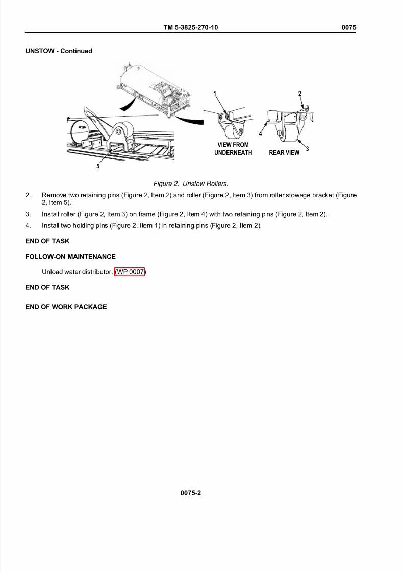
8/6/2019 TM 5-3825-270-10 ENGINEER MISSION MODULE WATER DISTRIBUTION
http://slidepdf.com/reader/full/tm-5-3825-270-10-engineer-mission-module-water-distribution 406/483
UNSTOW - Continued
5
2
REAR VIEW
VIEW FROM
UNDERNEATH
1
4
3
Figure 2. Unstow Rollers.
2. Remove two retaining pins (Figure 2, Item 2) and roller (Figure 2, Item 3) from roller stowage bracket (Figure
2, Item 5).
3. Install roller (Figure 2, Item 3) on frame (Figure 2, Item 4) with two retaining pins (Figure 2, Item 2).
4. Install two holding pins (Figure 2, Item 1) in retaining pins (Figure 2, Item 2).
END OF TASK
FOLLOW-ON MAINTENANCE
Unload water distributor. (WP 0007)
END OF TASK
END OF WORK PACKAGE
TM 5-3825-270-10 0075
0075-2

8/6/2019 TM 5-3825-270-10 ENGINEER MISSION MODULE WATER DISTRIBUTION
http://slidepdf.com/reader/full/tm-5-3825-270-10-engineer-mission-module-water-distribution 407/483
OPERATOR MAINTENANCESTOW\UNSTOW LADDER
INITIAL SETUP:
Not Applicable
UNSTOW LADDER
1. Remove tie down strap (Figure 1, Item 1) and slide ladder (Figure 1, Item 2) out of frame (Figure 1, Item 3).
2
4
1
3
Figure 1. Unstow Ladder.
2. Position ladder (Figure 1, Item 2) on the ground with hooks (Figure 1, Item 4 ) facing toward water distributo
WARNING
Keep fingers away from pinch points. Fingers may be pinched. Failure to comply may resultin injury or death to personnel.
WARNING
• Ladder is intended for use on the water distributor. The two hooks on the ladder must be
installed in the holes located on top of the mounting point to use. Failure to comply mayresult in injury or death to personnel.
TM 5-3825-270-10 0076
0076-1

8/6/2019 TM 5-3825-270-10 ENGINEER MISSION MODULE WATER DISTRIBUTION
http://slidepdf.com/reader/full/tm-5-3825-270-10-engineer-mission-module-water-distribution 408/483
UNSTOW LADDER - Continued
• Ensure ladder is stable against vehicle prior to use. Failure to comply may result in injuryor death to personnel.
• Ensure that the ladder is clean and free of debris or personnel may slip. Failure to complymay result in injury or death to personnel.
NOTE
There are 17 mounting points in which to position ladder on the water distributor. One isshown.
3. Install hooks (Figure 2, Item 4) of ladder (Figure 2, Item 2 ) in holes at desired location on frame (Figure 2,Item 3).
2 3 4
Figure 2. Unstow Ladder.
END OF TASK
STOW LADDER
1. Remove ladder (Figure 3, Item 2) from frame (Figure 3, Item 3).
2 3 4
Figure 3. Stow Ladder.
TM 5-3825-270-10 0076
0076-2

8/6/2019 TM 5-3825-270-10 ENGINEER MISSION MODULE WATER DISTRIBUTION
http://slidepdf.com/reader/full/tm-5-3825-270-10-engineer-mission-module-water-distribution 409/483
STOW LADDER - Continued
WARNING
Keep hands and fingers clear of ladder rungs and sides when placing ladder in the stowedposition. Failure to comply may result in injury or death to personnel.
2. Position ladder (Figure 3, Item 2) on the ground in the upright position with hooks (Figure 3, Item 4) facingtoward water distributor.
3. Slide ladder (Figure 4, Item 2) into frame (Figure 4, Item 3) with hooks (Figure 4, Item 4) facing up and secuwith tie down strap (Figure 4, Item 1).
2
4
1
3
Figure 4. Stow Ladder.
END OF TASK
END OF WORK PACKAGE
TM 5-3825-270-10 0076
0076-3/4 blank

8/6/2019 TM 5-3825-270-10 ENGINEER MISSION MODULE WATER DISTRIBUTION
http://slidepdf.com/reader/full/tm-5-3825-270-10-engineer-mission-module-water-distribution 410/483

8/6/2019 TM 5-3825-270-10 ENGINEER MISSION MODULE WATER DISTRIBUTION
http://slidepdf.com/reader/full/tm-5-3825-270-10-engineer-mission-module-water-distribution 411/483
OPERATOR MAINTENANCESTOW/UNSTOW RAILING
INITIAL SETUP:
Not Applicable
STOW
1. Remove two retaining pins (Figure 1, Item 1) from folding handrail assembly (Figure 1, Item 2).
21
Figure 1. Stow Railing.
WARNING
Keep fingers away from pinch points. Fingers may be pinched. Failure to comply may resultin injury or death to personnel.
2. Fold handrail assembly (Figure 2, Item 2) down into the stowed position, and install two retaining pins (Figur2, Item 1).
TM 5-3825-270-10 0077
0077-1

8/6/2019 TM 5-3825-270-10 ENGINEER MISSION MODULE WATER DISTRIBUTION
http://slidepdf.com/reader/full/tm-5-3825-270-10-engineer-mission-module-water-distribution 412/483
STOW - Continued
2
1
Figure 2. Stow Railing.
3. Secure folding handrail assembly (Figure 3, Item 2) to rear platform (Figure 3, Item 3) with tie down strap.
2
3
TIE
DOWN
STRAP
Figure 3. Stow Railing.
END OF TASK
UNSTOW
1. Release tie down strap from folding handrail assembly (Figure 4, Item 2) and rear platform (Figure 4, Item 3).
TM 5-3825-270-10 0077
0077-2
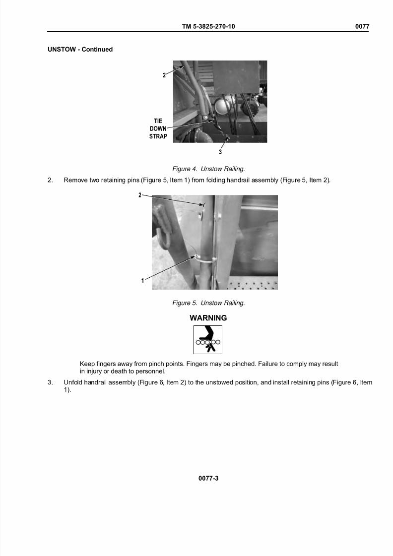
8/6/2019 TM 5-3825-270-10 ENGINEER MISSION MODULE WATER DISTRIBUTION
http://slidepdf.com/reader/full/tm-5-3825-270-10-engineer-mission-module-water-distribution 413/483
UNSTOW - Continued
2
3
TIE
DOWN
STRAP
Figure 4. Unstow Railing.
2. Remove two retaining pins (Figure 5, Item 1) from folding handrail assembly (Figure 5, Item 2).
2
1
Figure 5. Unstow Railing.
WARNING
Keep fingers away from pinch points. Fingers may be pinched. Failure to comply may resultin injury or death to personnel.
3. Unfold handrail assembly (Figure 6, Item 2) to the unstowed position, and install retaining pins (Figure 6, Item
1).
TM 5-3825-270-10 0077
0077-3

8/6/2019 TM 5-3825-270-10 ENGINEER MISSION MODULE WATER DISTRIBUTION
http://slidepdf.com/reader/full/tm-5-3825-270-10-engineer-mission-module-water-distribution 414/483
UNSTOW - Continued
21
Figure 6. Unstow Railing.
END OF TASK
END OF WORK PACKAGE
TM 5-3825-270-10 0077
0077-4
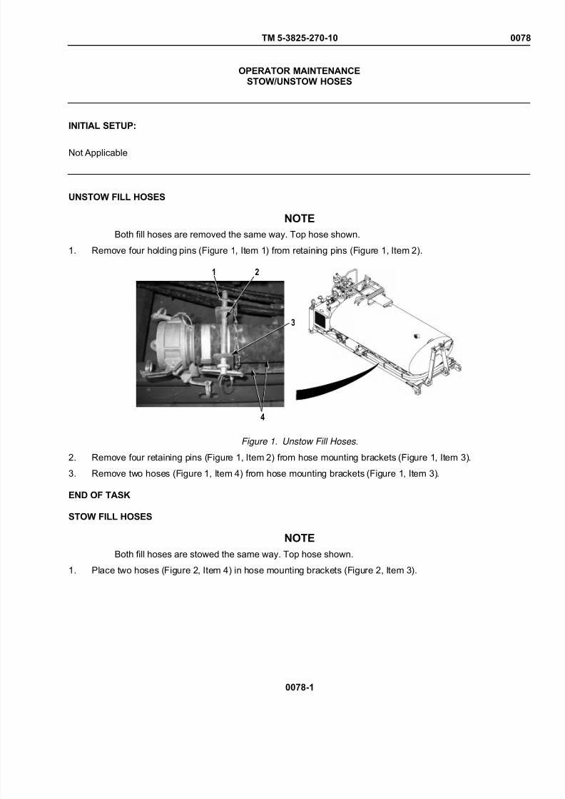
8/6/2019 TM 5-3825-270-10 ENGINEER MISSION MODULE WATER DISTRIBUTION
http://slidepdf.com/reader/full/tm-5-3825-270-10-engineer-mission-module-water-distribution 415/483
OPERATOR MAINTENANCESTOW/UNSTOW HOSES
INITIAL SETUP:
Not Applicable
UNSTOW FILL HOSES
NOTE
Both fill hoses are removed the same way. Top hose shown.
1. Remove four holding pins (Figure 1, Item 1) from retaining pins (Figure 1, Item 2).
21
3
4
Figure 1. Unstow Fill Hoses.
2. Remove four retaining pins (Figure 1, Item 2) from hose mounting brackets (Figure 1, Item 3).
3. Remove two hoses (Figure 1, Item 4) from hose mounting brackets (Figure 1, Item 3).
END OF TASK
STOW FILL HOSES
NOTE
Both fill hoses are stowed the same way. Top hose shown.
1. Place two hoses (Figure 2, Item 4) in hose mounting brackets (Figure 2, Item 3).
TM 5-3825-270-10 0078
0078-1

8/6/2019 TM 5-3825-270-10 ENGINEER MISSION MODULE WATER DISTRIBUTION
http://slidepdf.com/reader/full/tm-5-3825-270-10-engineer-mission-module-water-distribution 416/483
STOW FILL HOSES - Continued
21
3
4
Figure 2. Stow Fill Hoses.
2. Install four retaining pins (Figure 2, Item 2) in hose mounting brackets (Figure 2, Item 3).3. Install four holding pins (Figure 2, Item 1) in retaining pins (Figure 1, Item 2).
END OF TASK
UNWIND HOSE REEL
1. Release tie down strap from frame (Figure 3, Item 1) and hose reel (Figure 3, Item 2).
2
3
1
TIE DOWN
STRAP
Figure 3. Unwind Hose Reel.
2. Unlock hose reel (Figure 3, Item 2) by pulling and turning locking pin (Figure 3, Item 3).
3. Remove retaining pin (Figure 4, Item 4) from hose hook (Figure 4, Item 5).
TM 5-3825-270-10 0078
0078-2

8/6/2019 TM 5-3825-270-10 ENGINEER MISSION MODULE WATER DISTRIBUTION
http://slidepdf.com/reader/full/tm-5-3825-270-10-engineer-mission-module-water-distribution 417/483
UNWIND HOSE REEL - Continued
4 5 6
Figure 4. Unwind Hose Reel.
4. With the aid of an assistant, pull hose (Figure 4, Item 6) to unwind.
END OF TASK
RETRACT HOSE REEL
1. Remove retaining pin (Figure 5, Item 7) from crank handle (Figure 5, Item 8) and crank handle from stowagebrackets (Figure 5, Item 9).
76 8
910
Figure 5. Retract Hose Reel.
2. Install crank handle (Figure 5, Item 8) on slotted shaft (Figure 5, Item 10).
3. Reel hose (Figure 5, Item 6) in by turning crank handle (Figure 5, Item 8) clockwise.
4. Remove crank handle (Figure 5, Item 8) from slotted shaft (Figure 5, Item 10) and return to stowage bracket(Figure 5, Item 9). Secure with retaining pin (Figure 5, Item 7).
5. Place hose (Figure 6, Item 6) in hose hook (Figure 6, Item 5) and secure with retaining pin (Figure 6, Item 4)
TM 5-3825-270-10 0078
0078-3

8/6/2019 TM 5-3825-270-10 ENGINEER MISSION MODULE WATER DISTRIBUTION
http://slidepdf.com/reader/full/tm-5-3825-270-10-engineer-mission-module-water-distribution 418/483
RETRACT HOSE REEL - Continued
4 5 6
Figure 6. Retract Hose Reel.
6. Lock hose reel (Figure 7, Item 2) into place by aligning hole in hose reel and locking pin (Figure 7, Item 3).
2
3
1
TIE DOWN
STRAP
Figure 7. Retract Hose Reel.
7. Secure hose reel (Figure 7, Item 2) to frame (Figure 7, Item 1) with tie down strap.
END OF TASK
END OF WORK PACKAGE
TM 5-3825-270-10 0078
0078-4

8/6/2019 TM 5-3825-270-10 ENGINEER MISSION MODULE WATER DISTRIBUTION
http://slidepdf.com/reader/full/tm-5-3825-270-10-engineer-mission-module-water-distribution 419/483
OPERATOR MAINTENANCESTOW/UNSTOW FLOATING STRAINER
INITIAL SETUP:
Equipment ConditionUnstow hoses. (WP 0078)
UNSTOW
1. Release tie down strap (Figure 1, Item 1) from floating strainer (Figure 1, Item 2) and frame (Figure 1, Item 3
1
2
3
Figure 1. Unstow Floating Strainer.
2. Remove floating strainer (Figure 1, Item 2) from frame (Figure 1, Item 3).
END OF TASK
STOW
1. Place floating strainer (Figure 2, Item 2) in frame (Figure 2, Item 3).
TM 5-3825-270-10 0079
0079-1
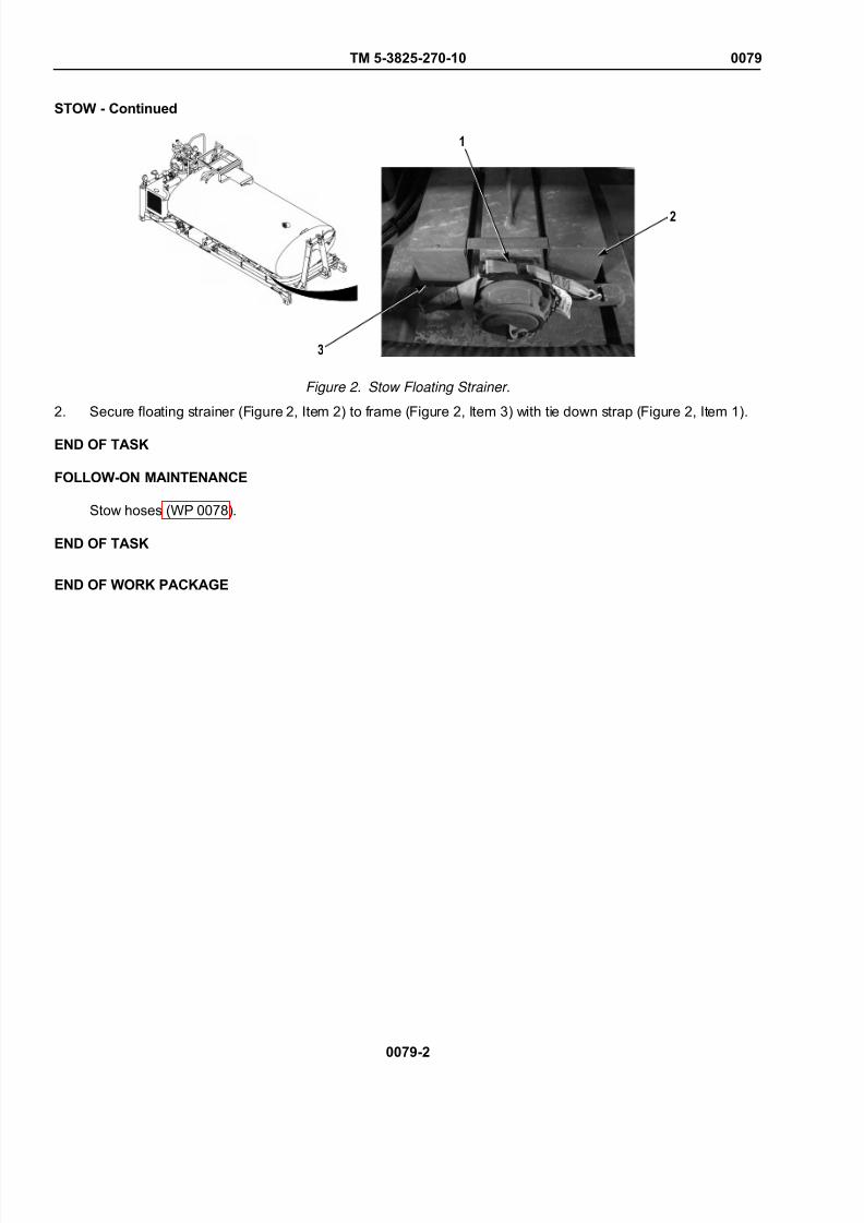
8/6/2019 TM 5-3825-270-10 ENGINEER MISSION MODULE WATER DISTRIBUTION
http://slidepdf.com/reader/full/tm-5-3825-270-10-engineer-mission-module-water-distribution 420/483
STOW - Continued
1
2
3
Figure 2. Stow Floating Strainer.
2. Secure floating strainer (Figure 2, Item 2) to frame (Figure 2, Item 3) with tie down strap (Figure 2, Item 1).
END OF TASK
FOLLOW-ON MAINTENANCE
Stow hoses (WP 0078).
END OF TASK
END OF WORK PACKAGE
TM 5-3825-270-10 0079
0079-2
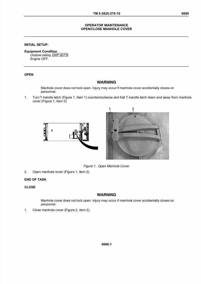
8/6/2019 TM 5-3825-270-10 ENGINEER MISSION MODULE WATER DISTRIBUTION
http://slidepdf.com/reader/full/tm-5-3825-270-10-engineer-mission-module-water-distribution 421/483
OPERATOR MAINTENANCEOPEN/CLOSE MANHOLE COVER
INITIAL SETUP:
Equipment ConditionUnstow railing. (WP 0077)Engine OFF.
OPEN
WARNING
Manhole cover does not lock open. Injury may occur if manhole cover accidentally closes onpersonnel.
1. Turn T-handle latch (Figure 1, Item 1) counterclockwise and fold T-handle latch down and away from manhocover (Figure 1, Item 2).
1 2
Figure 1. Open Manhole Cover.
2. Open manhole cover (Figure 1, Item 2).
END OF TASK
CLOSE
WARNING
Manhole cover does not lock open. Injury may occur if manhole cover accidentally closes onpersonnel.
1. Close manhole cover (Figure 2, Item 2).
TM 5-3825-270-10 0080
0080-1

8/6/2019 TM 5-3825-270-10 ENGINEER MISSION MODULE WATER DISTRIBUTION
http://slidepdf.com/reader/full/tm-5-3825-270-10-engineer-mission-module-water-distribution 422/483
CLOSE - Continued
1 2
Figure 2. Close Manhole Cover.
2. Place T-handle latch (Figure 2, Item 1) in manhole cover (Figure 2, Item 2) and turn T-handle latch clockwise
until tight.
END OF TASK
FOLLOW-ON MAINTENANCE
Stow railing. (WP 0077)
END OF TASK
END OF WORK PACKAGE
TM 5-3825-270-10 0080
0080-2

8/6/2019 TM 5-3825-270-10 ENGINEER MISSION MODULE WATER DISTRIBUTION
http://slidepdf.com/reader/full/tm-5-3825-270-10-engineer-mission-module-water-distribution 423/483
OPERATOR MAINTENANCEOPEN/CLOSE BATTERY BOX
INITIAL SETUP:
Equipment ConditionEngine OFF.
OPEN BATTERY BOX COVER
WARNING
To avoid eye injury, eye protection is required when working around batteries. Do not smoke,use open flame, make sparks or create other ignition sources around batteries. If a batteryis giving off gases, it can explode. Remove all jewelry, such as rings, ID tags, watches andbracelets. If jewelry contacts a battery terminal, a direct short will result in instant heating of tools, damage to equipment. Failure to comply may result in injury or death to personnel.
1. Disconnect two rubber hooks (Figure 1, Item 1) from battery box (Figure 1, Item 3).
21
3
Figure 1. Open Battery Box.
2. Lift cover (Figure 1, Item 2) up and away from battery box (Figure 1, Item 3).
END OF TASK
TM 5-3825-270-10 0081
0081-1
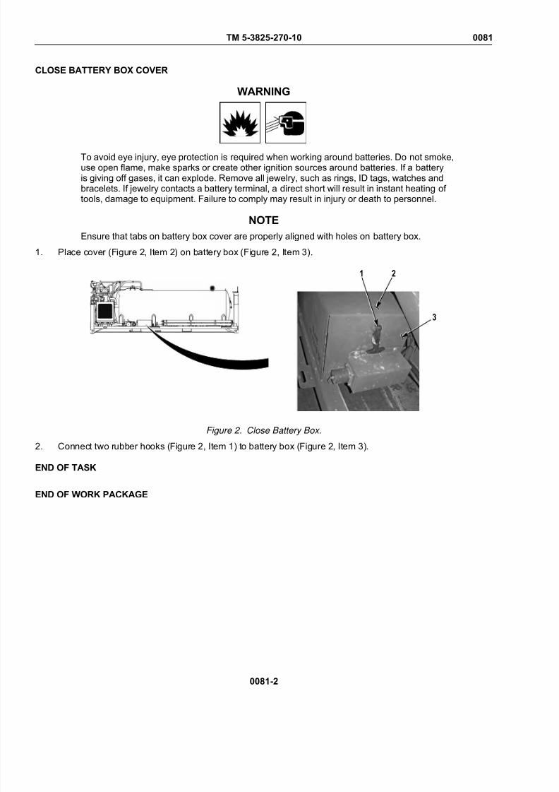
8/6/2019 TM 5-3825-270-10 ENGINEER MISSION MODULE WATER DISTRIBUTION
http://slidepdf.com/reader/full/tm-5-3825-270-10-engineer-mission-module-water-distribution 424/483
CLOSE BATTERY BOX COVER
WARNING
To avoid eye injury, eye protection is required when working around batteries. Do not smoke,use open flame, make sparks or create other ignition sources around batteries. If a batteryis giving off gases, it can explode. Remove all jewelry, such as rings, ID tags, watches andbracelets. If jewelry contacts a battery terminal, a direct short will result in instant heating of tools, damage to equipment. Failure to comply may result in injury or death to personnel.
NOTE
Ensure that tabs on battery box cover are properly aligned with holes on battery box.
1. Place cover (Figure 2, Item 2) on battery box (Figure 2, Item 3).
21
3
Figure 2. Close Battery Box.
2. Connect two rubber hooks (Figure 2, Item 1) to battery box (Figure 2, Item 3).
END OF TASK
END OF WORK PACKAGE
TM 5-3825-270-10 0081
0081-2

8/6/2019 TM 5-3825-270-10 ENGINEER MISSION MODULE WATER DISTRIBUTION
http://slidepdf.com/reader/full/tm-5-3825-270-10-engineer-mission-module-water-distribution 425/483
OPERATOR MAINTENANCEOPEN/CLOSE ENGINE ACCESS COVERS
INITIAL SETUP:
Equipment ConditionEngine OFF.
OPEN ENGINE ACCESS COVER
NOTE
Both engine access covers are opened the same way. Rear engine access cover is shown.
1. Turn handle (Figure 1, Item 1) clockwise.
1 2 3
Figure 1. Open Engine Access Cover.
2. Remove engine access cover (Figure 1, Item 2) from frame (Figure 1, Item 3).
END OF TASK
CLOSE ENGINE ACCESS COVER
NOTE
Both engine access covers are closed the same way. Rear engine access cover is shown.
1. Install engine access cover (Figure 2, Item 2) on frame (Figure 2, Item 3).
TM 5-3825-270-10 0082
0082-1

8/6/2019 TM 5-3825-270-10 ENGINEER MISSION MODULE WATER DISTRIBUTION
http://slidepdf.com/reader/full/tm-5-3825-270-10-engineer-mission-module-water-distribution 426/483
CLOSE ENGINE ACCESS COVER - Continued
1 2 3
Figure 2. Close Engine Access Cover.
2. Turn handle (Figure 2, Item 1) counterclockwise to stop.
END OF TASK
END OF WORK PACKAGE
TM 5-3825-270-10 0082
0082-2

8/6/2019 TM 5-3825-270-10 ENGINEER MISSION MODULE WATER DISTRIBUTION
http://slidepdf.com/reader/full/tm-5-3825-270-10-engineer-mission-module-water-distribution 427/483
OPERATOR MAINTENANCECLEANING
INITIAL SETUP:
Not Applicable
CLEANING SOLVENTS
WARNING
SOLVENT CLEANING COMPOUND (DRYCLEANING SOLVENT)
• Solvent cleaning compound MIL-PRF-680 Type II and III may be irritating to the eyes andskin. Use protective gloves and goggles. Use in a well-ventilated area. Use respirator asneeded. Accidental ingestion can cause irritation of digestive tract and respiratory tract,may cause lung and central nervous system damage. Can be fatal if swallowed.Inhalation of high/massive concentrations can cause coma or be fatal. First aid for ingestion: do not induce vomiting. Seek immediate medical attention. First aid for skincontact: remove contaminated clothing. Wash skin thoroughly with soap and water. If symptoms persist, seek medical attention. First aid for eye contact: flush with water for 15 minutes or until irritation subsides. If symptoms persist, seek medical attention. Firstaid for inhalation: move to fresh air. If not breathing, provide artificial respiration. If symptoms persist, seek medical attention. Keep away from open flames and other
sources of ignition. Failure to comply may result in injury or death to personnel.
• The flashpoint for Type II solvent cleaning compound is 141 to 198°F (61 to 92°C), andType III is 200 to 241°F (93 to 116°C).
• Improper cleaning methods and use of unauthorized cleaning solvents may result in injuryto personnel and/or damage to equipment.
• Fire extinguishers should be placed nearby when using solvent cleaning compound.Failure to comply may result in injury or death to personnel.
• Cloths or rags saturated with solvent cleaning compound must be disposed of IAWauthorized facilities' procedures. Failure to comply may result in injury to personnel.
• Eye shields must be worn when cleaning with a wire brush. Failure to comply may resultin injury to personnel.
• If personnel become dizzy while using cleaning solvent, immediately get fresh air andmedical help. If solvent contacts skin or clothes, flush with cold water. If solvent contactseyes, immediately flush eyes with water and get immediate medical attention. Failure tocomply may result in injury or death to personnel.
TM 5-3825-270-10 0083
0083-1
8/6/2019 TM 5-3825-270-10 ENGINEER MISSION MODULE WATER DISTRIBUTION
http://slidepdf.com/reader/full/tm-5-3825-270-10-engineer-mission-module-water-distribution 428/483
CLEANING SOLVENTS - Continued
WARNING
Compressed air used for cleaning and drying purposes must not exceed 30 psi (207 kPa).Use only with effective chip guarding and proper protective equipment (goggles, shield,gloves, etc.). Failure to comply may result in injury or death to personnel.
Use only approved cleaning solvents to clean parts. Solvent cleaning compound is commonly used. Always work ina well-ventilated area.
END OF TASK
REMOVING DEPOSITS
WARNING
SOLVENT CLEANING COMPOUND (DRYCLEANING SOLVENT)
• Solvent cleaning compound MIL-PRF-680 Type II and III may be irritating to the eyes andskin. Use protective gloves and goggles. Use in a well-ventilated area. Use respirator asneeded. Accidental ingestion can cause irritation of digestive tract and respiratory tract,may cause lung and central nervous system damage. Can be fatal if swallowed.Inhalation of high/massive concentrations can cause coma or be fatal. First aid for ingestion: do not induce vomiting. Seek immediate medical attention. First aid for skin
contact: remove contaminated clothing. Wash skin thoroughly with soap and water. If symptoms persist, seek medical attention. First aid for eye contact: flush with water for 15 minutes or until irritation subsides. If symptoms persist, seek medical attention. Firstaid for inhalation: move to fresh air. If not breathing, provide artificial respiration. If symptoms persist, seek medical attention. Keep away from open flames and other sources of ignition. Failure to comply may result in injury or death to personnel.
• The flashpoint for Type II solvent cleaning compound is 141 to 198°F (61 to 92°C), andType III is 200 to 241°F (93 to 116°C).
• Improper cleaning methods and use of unauthorized cleaning solvents may result in injuryto personnel and/or damage to equipment.
• Fire extinguishers should be placed nearby when using solvent cleaning compound.Failure to comply may result in injury or death to personnel.
• Cloths or rags saturated with solvent cleaning compound must be disposed of IAWauthorized facilities' procedures. Failure to comply may result in injury to personnel.
• Eye shields must be worn when cleaning with a wire brush. Failure to comply may resultin injury to personnel.
• If personnel become dizzy while using cleaning solvent, immediately get fresh air andmedical help. If solvent contacts skin or clothes, flush with cold water. If solvent contacts
TM 5-3825-270-10 0083
0083-2

8/6/2019 TM 5-3825-270-10 ENGINEER MISSION MODULE WATER DISTRIBUTION
http://slidepdf.com/reader/full/tm-5-3825-270-10-engineer-mission-module-water-distribution 429/483
REMOVING DEPOSITS - Continued
eyes, immediately flush eyes with water and get immediate medical attention. Failure tocomply may result in injury or death to personnel.
Soak parts in Solvent cleaning compound and wash away deposits by flushing or spraying. When necessary, bruswith a soft bristle brush (not wire) moistened in solvent. Use compressed air to dry parts, except bearings, after
cleaning. Bearings must drip and air dry.
END OF TASK
TOOLS
Do not use wire brushes, abrasive wheels, or compounds to clean parts unless specifically approved in the detaileprocedures. Parts may be scratched or altered and may weaken a highly stressed part.
END OF TASK
BALL AND ROLLER BEARINGS
WARNING
SOLVENT CLEANING COMPOUND (DRYCLEANING SOLVENT)
• Solvent cleaning compound MIL-PRF-680 Type II and III may be irritating to the eyes andskin. Use protective gloves and goggles. Use in a well-ventilated area. Use respirator asneeded. Accidental ingestion can cause irritation of digestive tract and respiratory tract,may cause lung and central nervous system damage. Can be fatal if swallowed.Inhalation of high/massive concentrations can cause coma or be fatal. First aid for
ingestion: do not induce vomiting. Seek immediate medical attention. First aid for skincontact: remove contaminated clothing. Wash skin thoroughly with soap and water. If symptoms persist, seek medical attention. First aid for eye contact: flush with water for 15 minutes or until irritation subsides. If symptoms persist, seek medical attention. Firstaid for inhalation: move to fresh air. If not breathing, provide artificial respiration. If symptoms persist, seek medical attention. Keep away from open flames and other sources of ignition. Failure to comply may result in injury or death to personnel.
• The flashpoint for Type II solvent cleaning compound is 141 to 198°F (61 to 92°C), andType III is 200 to 241°F (93 to 116°C).
• Improper cleaning methods and use of unauthorized cleaning solvents may result in injuryto personnel and/or damage to equipment.
• Fire extinguishers should be placed nearby when using solvent cleaning compound.
Failure to comply may result in injury or death to personnel.
• Cloths or rags saturated with solvent cleaning compound must be disposed of IAWauthorized facilities' procedures. Failure to comply may result in injury to personnel.
• Eye shields must be worn when cleaning with a wire brush. Failure to comply may resultin injury to personnel.
• If personnel become dizzy while using cleaning solvent, immediately get fresh air andmedical help. If solvent contacts skin or clothes, flush with cold water. If solvent contacts
TM 5-3825-270-10 0083
0083-3

8/6/2019 TM 5-3825-270-10 ENGINEER MISSION MODULE WATER DISTRIBUTION
http://slidepdf.com/reader/full/tm-5-3825-270-10-engineer-mission-module-water-distribution 430/483
BALL AND ROLLER BEARINGS - Continued
eyes, immediately flush eyes with water and get immediate medical attention. Failure tocomply may result in injury or death to personnel.
When cleaning ball or roller bearings, place them in a basket and suspend them in a container of solvent cleaningcompound. If needed, use a brush to remove caked grease, chips, etc. Avoid rotating bearing before solid particles
are removed to prevent damaging races and balls. When bearings have been cleaned, coat them lightly withlubricating oil to remove solvent.
END OF TASK
RUBBER PARTS
CAUTION
Do not clean lubricant seals, rubber hoses, or electrical components with solvent mixture.Failure to comply may result in damage to equipment.
Do not clean preformed packings or rubber parts in solvent cleaning compound. Wipe parts clean with a dry, cleaningcloth.
END OF TASK
EXTERIOR PARTS
WARNING
Steam cleaning creates hazardous noise levels and severe burn potential. Eye, skin, and ear protection is required. Failure to comply may result in injury or death to personnel.
Steam clean all exterior parts thoroughly before removing. This will make inspection and disassembly easier.
END OF TASK
ENGINE AND FRAME
WARNING
Solvents used with a spray gun must be used in a spray booth with a filter. Face shield mustbe used by personnel operating spray gun. Failure to comply may result in injury or death topersonnel.
Use a spray gun and solvent mixture for cleaning of engine and frame. Allow mixture to remain on item surface for 10 minutes before rinsing. Rinse with hot water at 80 to 120 psi (551 to 827 Kpa), if available. An ordinary gardenhose with nozzle may be used if other equipment is not available. Rinse thoroughly.
END OF TASK
TM 5-3825-270-10 0083
0083-4

8/6/2019 TM 5-3825-270-10 ENGINEER MISSION MODULE WATER DISTRIBUTION
http://slidepdf.com/reader/full/tm-5-3825-270-10-engineer-mission-module-water-distribution 431/483
WATER TANK AND SPRAYING EQUIPMENT MAINTENANCE
Immediately following the use of soil stabilization additive or equivalent, the Water Distributor and all sprayingequipment MUST be flushed through all valves and ports that the product came in contact with. The Water Distribumust be flushed three times using 1,000 gallons (3,785.4 L) of water by using the recommended practice:
• Drain all existing material/liquid at the 5" hydrant port• Fill tank with 1000 gallons of water, flush a combined 800 gallons of water through the water turret and
flusher nozzles, drain remaining 200 gallons at 5" hydrant port (C2)• Fill tank with 1000 gallons of water, flush a combined 800 gallons of water through the water turret, flushe
nozzles and hose reel, drain remaining 200 gallons at 5" hydrant port (C2)• Fill tank with 1000 gallons of water, flush a combined 500 gallons of water through the water turret and
flusher nozzles, use 200 gallons to rinse soil additive residue from rear of module using the hose reel, draremaining 300 gallons at the 2.5" hydrant ports (C3 and C4), gravity bar and petcocks (P1, P2, P3, P4)
END OF TASK
DEGREASING MACHINE
WARNING
SOLVENT CLEANING COMPOUND (DRYCLEANING SOLVENT)
• Solvent cleaning compound MIL-PRF-680 Type II and III may be irritating to the eyes andskin. Use protective gloves and goggles. Use in a well-ventilated area. Use respirator asneeded. Accidental ingestion can cause irritation of digestive tract and respiratory tract,may cause lung and central nervous system damage. Can be fatal if swallowed.Inhalation of high/massive concentrations can cause coma or be fatal. First aid for ingestion: do not induce vomiting. Seek immediate medical attention. First aid for skincontact: remove contaminated clothing. Wash skin thoroughly with soap and water. If symptoms persist, seek medical attention. First aid for eye contact: flush with water for 15 minutes or until irritation subsides. If symptoms persist, seek medical attention. Firstaid for inhalation: move to fresh air. If not breathing, provide artificial respiration. If symptoms persist, seek medical attention. Keep away from open flames and other sources of ignition. Failure to comply may result in injury or death to personnel.
• The flashpoint for Type II solvent cleaning compound is 141 to 198°F (61 to 92°C), andType III is 200 to 241°F (93 to 116°C).
• Improper cleaning methods and use of unauthorized cleaning solvents may result in injuryto personnel and/or damage to equipment.
• Fire extinguishers should be placed nearby when using solvent cleaning compound.Failure to comply may result in injury or death to personnel.
• Cloths or rags saturated with solvent cleaning compound must be disposed of IAWauthorized facilities' procedures. Failure to comply may result in injury to personnel.
• Eye shields must be worn when cleaning with a wire brush. Failure to comply may resultin injury to personnel.
• If personnel become dizzy while using cleaning solvent, immediately get fresh air andmedical help. If solvent contacts skin or clothes, flush with cold water. If solvent contactseyes, immediately flush eyes with water and get immediate medical attention. Failure tocomply may result in injury or death to personnel.
TM 5-3825-270-10 0083
0083-5

8/6/2019 TM 5-3825-270-10 ENGINEER MISSION MODULE WATER DISTRIBUTION
http://slidepdf.com/reader/full/tm-5-3825-270-10-engineer-mission-module-water-distribution 432/483
DEGREASING MACHINE - Continued
WARNING
Never use fuel to clean parts. Fuel is highly flammable. Failure to comply may result in injuryor death to personnel.
CAUTION
To prevent corrosion, parts should be dipped in rust preventive within two hours of degreasing. Failure to comply may result in damage to equipment.
A degreasing machine may be used to remove heavy grease and oil from metal parts.
END OF TASK
PASSAGES
WARNING
SOLVENT CLEANING COMPOUND (DRYCLEANING SOLVENT)
• Solvent cleaning compound MIL-PRF-680 Type II and III may be irritating to the eyes andskin. Use protective gloves and goggles. Use in a well-ventilated area. Use respirator asneeded. Accidental ingestion can cause irritation of digestive tract and respiratory tract,
may cause lung and central nervous system damage. Can be fatal if swallowed.Inhalation of high/massive concentrations can cause coma or be fatal. First aid for ingestion: do not induce vomiting. Seek immediate medical attention. First aid for skincontact: remove contaminated clothing. Wash skin thoroughly with soap and water. If symptoms persist, seek medical attention. First aid for eye contact: flush with water for 15 minutes or until irritation subsides. If symptoms persist, seek medical attention. Firstaid for inhalation: move to fresh air. If not breathing, provide artificial respiration. If symptoms persist, seek medical attention. Keep away from open flames and other sources of ignition. Failure to comply may result in injury or death to personnel.
• The flashpoint for Type II solvent cleaning compound is 141 to 198°F (61 to 92°C), andType III is 200 to 241°F (93 to 116°C).
• Improper cleaning methods and use of unauthorized cleaning solvents may result in injuryto personnel and/or damage to equipment.
• Fire extinguishers should be placed nearby when using solvent cleaning compound.Failure to comply may result in injury or death to personnel.
• Cloths or rags saturated with solvent cleaning compound must be disposed of IAWauthorized facilities' procedures. Failure to comply may result in injury to personnel.
• Eye shields must be worn when cleaning with a wire brush. Failure to comply may resultin injury to personnel.
TM 5-3825-270-10 0083
0083-6

8/6/2019 TM 5-3825-270-10 ENGINEER MISSION MODULE WATER DISTRIBUTION
http://slidepdf.com/reader/full/tm-5-3825-270-10-engineer-mission-module-water-distribution 433/483
PASSAGES - Continued
• If personnel become dizzy while using cleaning solvent, immediately get fresh air andmedical help. If solvent contacts skin or clothes, flush with cold water. If solvent contactseyes, immediately flush eyes with water and get immediate medical attention. Failure tocomply may result in injury or death to personnel.
After degreasing, check all oil passages and cavities for dirt or blockage before coating with lubricating oil. Run athin, flexible wire through oil passages to make sure they are not clogged. Use a pressure spray gun and solventcleaning compound to clean dirty passages.
END OF TASK
ELECTRICAL PARTS
WARNING
SOLVENT CLEANING COMPOUND (DRYCLEANING SOLVENT)
• Solvent cleaning compound MIL-PRF-680 Type II and III may be irritating to the eyes andskin. Use protective gloves and goggles. Use in a well-ventilated area. Use respirator asneeded. Accidental ingestion can cause irritation of digestive tract and respiratory tract,may cause lung and central nervous system damage. Can be fatal if swallowed.Inhalation of high/massive concentrations can cause coma or be fatal. First aid for ingestion: do not induce vomiting. Seek immediate medical attention. First aid for skincontact: remove contaminated clothing. Wash skin thoroughly with soap and water. If symptoms persist, seek medical attention. First aid for eye contact: flush with water for 15 minutes or until irritation subsides. If symptoms persist, seek medical attention. Firstaid for inhalation: move to fresh air. If not breathing, provide artificial respiration. If
symptoms persist, seek medical attention. Keep away from open flames and other sources of ignition. Failure to comply may result in injury or death to personnel.
• The flashpoint for Type II solvent cleaning compound is 141 to 198°F (61 to 92°C), andType III is 200 to 241°F (93 to 116°C).
• Improper cleaning methods and use of unauthorized cleaning solvents may result in injuryto personnel and/or damage to equipment.
• Fire extinguishers should be placed nearby when using solvent cleaning compound.Failure to comply may result in injury or death to personnel.
• Cloths or rags saturated with solvent cleaning compound must be disposed of IAWauthorized facilities' procedures. Failure to comply may result in injury to personnel.
• Eye shields must be worn when cleaning with a wire brush. Failure to comply may result
in injury to personnel.
• If personnel become dizzy while using cleaning solvent, immediately get fresh air andmedical help. If solvent contacts skin or clothes, flush with cold water. If solvent contactseyes, immediately flush eyes with water and get immediate medical attention. Failure tocomply may result in injury or death to personnel.
TM 5-3825-270-10 0083
0083-7

8/6/2019 TM 5-3825-270-10 ENGINEER MISSION MODULE WATER DISTRIBUTION
http://slidepdf.com/reader/full/tm-5-3825-270-10-engineer-mission-module-water-distribution 434/483
ELECTRICAL PARTS - Continued
Electrical parts, such as coils, junction blocks, and switches should not be soaked or sprayed with cleaning solutions.Clean these parts with a clean cloth moistened with solvent cleaning compound.
END OF TASK
END OF WORK PACKAGE
TM 5-3825-270-10 0083
0083-8

8/6/2019 TM 5-3825-270-10 ENGINEER MISSION MODULE WATER DISTRIBUTION
http://slidepdf.com/reader/full/tm-5-3825-270-10-engineer-mission-module-water-distribution 435/483
OPERATOR MAINTENANCEDATA PLATES AND STENCILS
INITIAL SETUP:
Not Applicable
DATA PLATES
Data plates and stencils see below:
Figure 1. Data Plates.
Figure 2. Data Plates.
TM 5-3825-270-10 0084
0084-1

8/6/2019 TM 5-3825-270-10 ENGINEER MISSION MODULE WATER DISTRIBUTION
http://slidepdf.com/reader/full/tm-5-3825-270-10-engineer-mission-module-water-distribution 436/483
DATA PLATES - Continued
Figure 3. Data Plates.
END OF TASK
STENCILS
1. The words "SLAVE", "24 VOLTS DC", and "NO STEP" are stenciled on the battery box cover.
Figure 4. Stencils.
2. The words "FORK LIFT EMPTY ONLY" are stenciled on both sides of the water distributor.
TM 5-3825-270-10 0084
0084-2

8/6/2019 TM 5-3825-270-10 ENGINEER MISSION MODULE WATER DISTRIBUTION
http://slidepdf.com/reader/full/tm-5-3825-270-10-engineer-mission-module-water-distribution 437/483
STENCILS - Continued
Figure 5. Stencils.
3. The words "NON-POTABLE WATER" are stenciled on both sides of the water distributor.
TM 5-3825-270-10 0084
0084-3
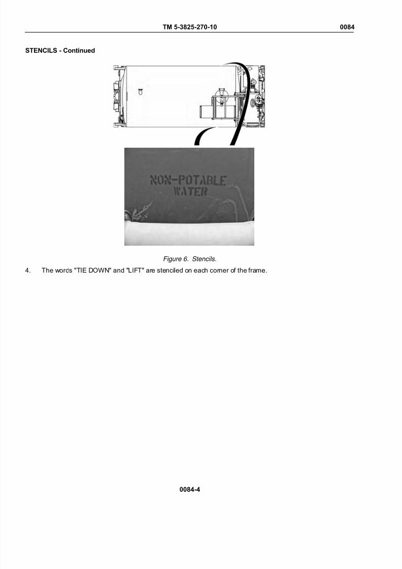
8/6/2019 TM 5-3825-270-10 ENGINEER MISSION MODULE WATER DISTRIBUTION
http://slidepdf.com/reader/full/tm-5-3825-270-10-engineer-mission-module-water-distribution 438/483
STENCILS - Continued
Figure 6. Stencils.
4. The words "TIE DOWN" and "LIFT" are stenciled on each corner of the frame.
TM 5-3825-270-10 0084
0084-4

8/6/2019 TM 5-3825-270-10 ENGINEER MISSION MODULE WATER DISTRIBUTION
http://slidepdf.com/reader/full/tm-5-3825-270-10-engineer-mission-module-water-distribution 439/483
STENCILS - Continued
Figure 7. Stencils.
5. The designation "DF2/JP8" and the word "DIESEL" are stenciled on the fuel tank.
TM 5-3825-270-10 0084
0084-5
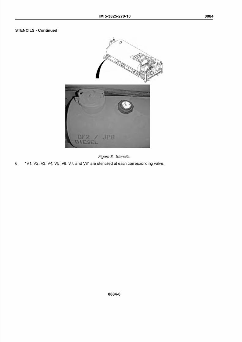
8/6/2019 TM 5-3825-270-10 ENGINEER MISSION MODULE WATER DISTRIBUTION
http://slidepdf.com/reader/full/tm-5-3825-270-10-engineer-mission-module-water-distribution 440/483
STENCILS - Continued
Figure 8. Stencils.
6. "V1, V2, V3, V4, V5, V6, V7, and V8" are stenciled at each corresponding valve.
TM 5-3825-270-10 0084
0084-6

8/6/2019 TM 5-3825-270-10 ENGINEER MISSION MODULE WATER DISTRIBUTION
http://slidepdf.com/reader/full/tm-5-3825-270-10-engineer-mission-module-water-distribution 441/483
STENCILS - Continued
Figure 9. Stencils.
7. The words "NO STEP" and "HOT EXHAUST" are stenciled on the engine module.
TM 5-3825-270-10 0084
0084-7

8/6/2019 TM 5-3825-270-10 ENGINEER MISSION MODULE WATER DISTRIBUTION
http://slidepdf.com/reader/full/tm-5-3825-270-10-engineer-mission-module-water-distribution 442/483
STENCILS - Continued
Figure 10. Stencils.
8. The words "DANGER, CONFINED SPACE, DO NOT ENTER, REFER TO TECHNICAL MANUAL, PERMITREQUIRED", and "NO STEP" are stenciled on the top of the water distributor tank.
TM 5-3825-270-10 0084
0084-8
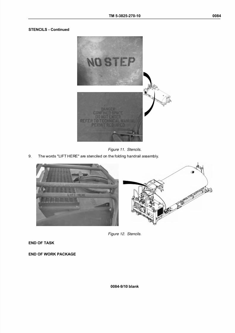
8/6/2019 TM 5-3825-270-10 ENGINEER MISSION MODULE WATER DISTRIBUTION
http://slidepdf.com/reader/full/tm-5-3825-270-10-engineer-mission-module-water-distribution 443/483
STENCILS - Continued
Figure 11. Stencils.
9. The words "LIFT HERE" are stenciled on the folding handrail assembly.
Figure 12. Stencils.
END OF TASK
END OF WORK PACKAGE
TM 5-3825-270-10 0084
0084-9/10 blank

8/6/2019 TM 5-3825-270-10 ENGINEER MISSION MODULE WATER DISTRIBUTION
http://slidepdf.com/reader/full/tm-5-3825-270-10-engineer-mission-module-water-distribution 444/483

8/6/2019 TM 5-3825-270-10 ENGINEER MISSION MODULE WATER DISTRIBUTION
http://slidepdf.com/reader/full/tm-5-3825-270-10-engineer-mission-module-water-distribution 445/483
OPERATOR MAINTENANCEOUTER AIR FILTER ELEMENT REMOVAL/SERVICE/INSTALLATION
INITIAL SETUP:
Materials/PartsRag, Wiping
Equipment ConditionEngine OFF.
REMOVAL
CAUTION
• Do not run engine after air filter element has been removed. Failure to comply may resultin damage to equipment.
• Do not determine air filter serviceability through visual inspection. Visual inspection maylead to over servicing of air filters. Failure to comply may result in damage to equipment.
1. Check air filter restriction indicator (Figure 1, Item 1) to determine air filter serviceability.
21
4
3
Figure 1. Air Filter Element Removal.
2. Release two latches (Figure 1, Item 4) and remove air cleaner housing cover (Figure 1, Item 3) from air cleahousing (Figure 1, Item 2).
CAUTION
Ensure inner air filter element is not removed when removing outer air filter element. If inner air filter element is accidentally removed, immediately reinstall inner air filter. Failure to
comply may result in damage to equipment.
3. Remove outer air filter element (Figure 2, Item 5) from air cleaner housing (Figure 2, Item 2).
TM 5-3825-270-10 0085
0085-1
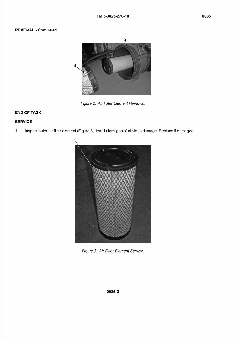
8/6/2019 TM 5-3825-270-10 ENGINEER MISSION MODULE WATER DISTRIBUTION
http://slidepdf.com/reader/full/tm-5-3825-270-10-engineer-mission-module-water-distribution 446/483
REMOVAL - Continued
2
5
Figure 2. Air Filter Element Removal.
END OF TASK
SERVICE
1. Inspect outer air filter element (Figure 3, Item 1) for signs of obvious damage. Replace if damaged.
1
Figure 3. Air Filter Element Service.
TM 5-3825-270-10 0085
0085-2
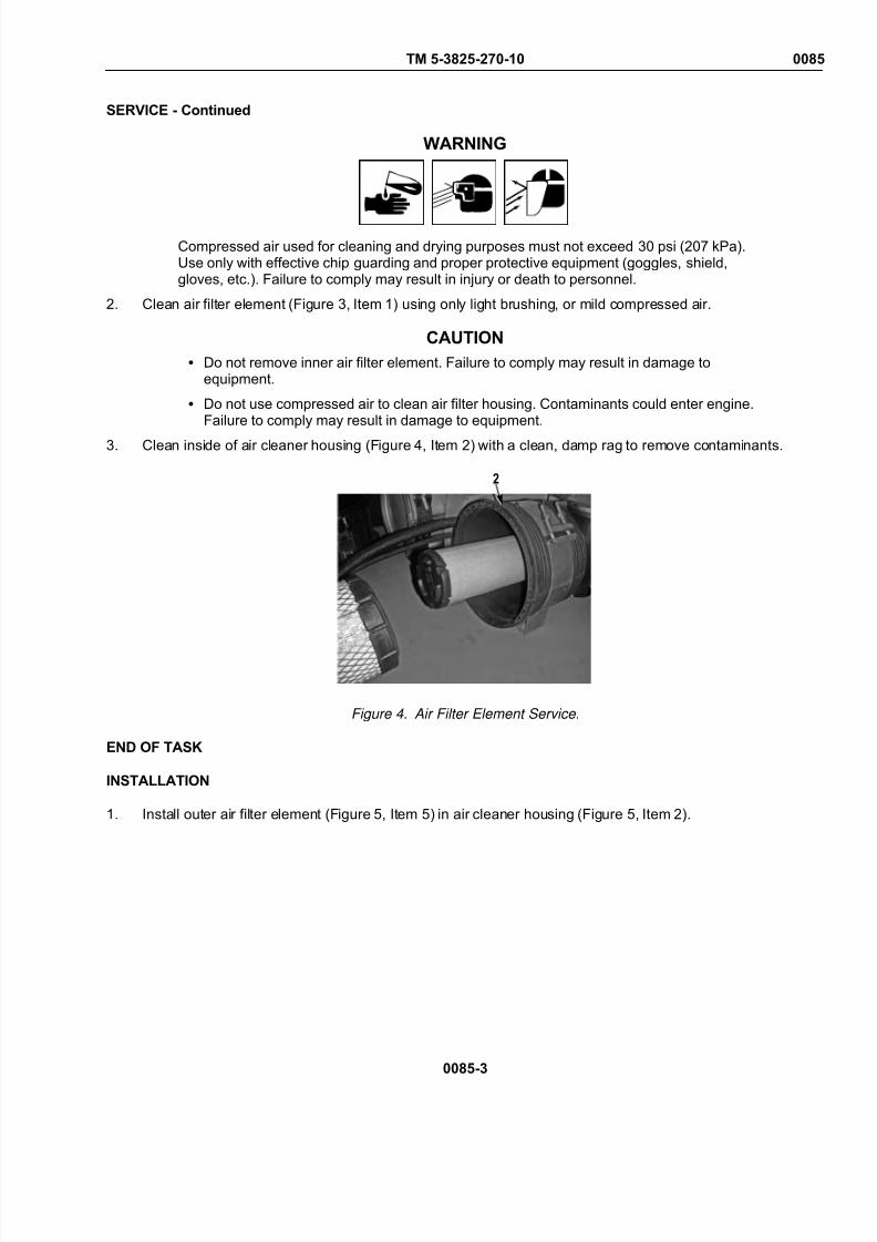
8/6/2019 TM 5-3825-270-10 ENGINEER MISSION MODULE WATER DISTRIBUTION
http://slidepdf.com/reader/full/tm-5-3825-270-10-engineer-mission-module-water-distribution 447/483
SERVICE - Continued
WARNING
Compressed air used for cleaning and drying purposes must not exceed 30 psi (207 kPa).Use only with effective chip guarding and proper protective equipment (goggles, shield,gloves, etc.). Failure to comply may result in injury or death to personnel.
2. Clean air filter element (Figure 3, Item 1) using only light brushing, or mild compressed air.
CAUTION
• Do not remove inner air filter element. Failure to comply may result in damage toequipment.
• Do not use compressed air to clean air filter housing. Contaminants could enter engine.Failure to comply may result in damage to equipment.
3. Clean inside of air cleaner housing (Figure 4, Item 2) with a clean, damp rag to remove contaminants.
2
Figure 4. Air Filter Element Service.
END OF TASK
INSTALLATION
1. Install outer air filter element (Figure 5, Item 5) in air cleaner housing (Figure 5, Item 2).
TM 5-3825-270-10 0085
0085-3

8/6/2019 TM 5-3825-270-10 ENGINEER MISSION MODULE WATER DISTRIBUTION
http://slidepdf.com/reader/full/tm-5-3825-270-10-engineer-mission-module-water-distribution 448/483
INSTALLATION - Continued
2
5
Figure 5. Air Filter Element Installation.
2. Install air cleaner housing cover (Figure 6, Item 3) with the word TOP facing up on air cleaner housing (Figure6, Item 2) and secure with two latches (Figure 6, Item 4).
2
4
3
Figure 6. Air Filter Element Installation.
3. Reset air filter restriction indicator (Figure 7, Item 1) by pressing in on rubber diaphragm (Figure 7, Item 6).
TM 5-3825-270-10 0085
0085-4

8/6/2019 TM 5-3825-270-10 ENGINEER MISSION MODULE WATER DISTRIBUTION
http://slidepdf.com/reader/full/tm-5-3825-270-10-engineer-mission-module-water-distribution 449/483
INSTALLATION - Continued
6
1
Figure 7. Air Filter Element Installation.
END OF TASK
END OF WORK PACKAGE
TM 5-3825-270-10 0085
0085-5/6 blank

8/6/2019 TM 5-3825-270-10 ENGINEER MISSION MODULE WATER DISTRIBUTION
http://slidepdf.com/reader/full/tm-5-3825-270-10-engineer-mission-module-water-distribution 450/483

8/6/2019 TM 5-3825-270-10 ENGINEER MISSION MODULE WATER DISTRIBUTION
http://slidepdf.com/reader/full/tm-5-3825-270-10-engineer-mission-module-water-distribution 451/483
CHAPTER 6
SUPPORTING INFORMATION
TM 5-3825-270-10

8/6/2019 TM 5-3825-270-10 ENGINEER MISSION MODULE WATER DISTRIBUTION
http://slidepdf.com/reader/full/tm-5-3825-270-10-engineer-mission-module-water-distribution 452/483

8/6/2019 TM 5-3825-270-10 ENGINEER MISSION MODULE WATER DISTRIBUTION
http://slidepdf.com/reader/full/tm-5-3825-270-10-engineer-mission-module-water-distribution 453/483
FIELD MAINTENANCEREFERENCES
SCOPE
This work package lists all the pamphlets, forms, field manuals, technical manuals, and other publications referredto in this manual. Also, those publications that should be consulted for additional information about water distributooperations are listed.
DEPARTMENT OF ARMY PAMPHLETS
MILITARY PUBLICATION INDEXES
DA PAM 750-8 The Army Maintenance Management System (TAMMS)Users Manual
FORMS
DA Form 2028 Recommended Changes to Publications and Blank Forms
DA Form 2404 Equipment Inspection and Maintenance Worksheet
DA Form 2407 Maintenance Request
DD Form 314 Preventive Maintenance Schedule and Record
DD Form 1397 Processing and Deprocessing Record for Shipment, Storageand Issue of Vehicles and Spare Engines
SF 368 Quality Deficiency Report
DA Form 5988-E Equipment Inspection/Maintenance Worksheet (EGA)SF 364 Supply Discrepancy Report
FIELD MANUALS
FM 21-10 Field Hygiene and Sanitation
TECHNICAL MANUALS
TM 5-3825-270-10 Water Distributor Operator Manual
TM 5-3825-270-23&P Field Maintenance Manual Including SustainmentMaintenance Repair Parts and Special Tools List for EMM -Water Distributor
TM 750-244-6 Procedures for Destruction of Tank-Automotive Equipment tPrevent Enemy Use (U.S. Army Tank-Automotive Command
TM 9-2320-364-10 Operator's Manual for Truck, Tractor, M1074 and M1075Palletized Load System (PLS)
TM 5-3825-270-10 0086
0086-1
8/6/2019 TM 5-3825-270-10 ENGINEER MISSION MODULE WATER DISTRIBUTION
http://slidepdf.com/reader/full/tm-5-3825-270-10-engineer-mission-module-water-distribution 454/483
TECHNICAL MANUALS - Continued
TM 9-2320-364-14&P Interactive Electronic Technical Manual for Palletzied LoadSystem (PLS) M1074, M1075, M1076, M1077
TM 9-247 Material used for Cleaning, Preserving, Abrading, and
Cementing Ordnance Material and Related Material includingChemicals.
MISCELLANEOUS PUBLICATIONS
TB 43-0209 Color, Marking, and Camouflage Painting of Military Vehicles,Construction Equipment, and Materials handling Equipment
LO-5-3825-270-13 Lubrication Order for EMM Water Distributor
TB 750-651 Use of Antifreeze Multi-Engine Type Cleaning Compoundsand Test Kit in Engine Cooling System
CTA 50-970 Expendable/Durable Items (Except Medical, Class V, Repair Parts, and Heraldic Item)
SF 368 Product Quality Deficiency Report
END OF WORK PACKAGE
TM 5-3825-270-10 0086
0086-2

8/6/2019 TM 5-3825-270-10 ENGINEER MISSION MODULE WATER DISTRIBUTION
http://slidepdf.com/reader/full/tm-5-3825-270-10-engineer-mission-module-water-distribution 455/483
OPERATOR MAINTENANCECOMPONENTS OF END ITEM AND BASIC ISSUE ITEMS LISTS
INTRODUCTION
Scope
This appendix lists components of end item and basic issue items for the Water Distributor, to help inventory itemsrequired for safe and efficient operation.
General
The Components of End Item and Basic Issue Items Lists are divided into the following sections:
Section II. Components of End Item
This listing is for informational purposes only, and is not authority for requisition replacements. These items are pa
of the end item, but are removed and separately packaged for transportation or shipment. As part of the end item,these items must be with the end item whenever it is issued or transferred between property accounts. Illustrationsare furnished to assist in identifying the items.
Section III. Basic Issue Items
These are the minimum essential items required to place the Water Distributor in operation, to operate it, and toperform emergency repairs. Although shipped separately packaged, BII must be with the Water Distributor duringoperation and whenever it is transferred between property accounts. The illustrations will assist with hard-to-identiitems. This manual is the authority to request/requisition replacement BII, based on TOE/MTOE authorization of thend item.
Explanation of Columns
The following provides an explanation of columns found in the tabular listings:
Column (1) - Item Number
Gives you the reference number of the item listed.
Column (2) - National Stock Number (NSN) and Illustration.
Identifies the stock number of the item to be used for requisitioning purposes and provides an illustration of the ite
Column (3) - Description, Part Number/(CAGEC).
Identifies the Federal item name (in all capital letters) followed by a minimum description when needed. The stowalocation of COEI and BII is also included in this column. The last line below the description is the part number andthe Commercial and Government Entity Code (CAGEC) (in parentheses).
Column (4) - Usable On Code
When applicable, gives you a code if the item you need is not the same for different models of equipment. Thesecodes are identified below:
Column (5) - U/I Unit of Issue (U/I)
TM 5-3825-270-10 0087
0087-1

8/6/2019 TM 5-3825-270-10 ENGINEER MISSION MODULE WATER DISTRIBUTION
http://slidepdf.com/reader/full/tm-5-3825-270-10-engineer-mission-module-water-distribution 456/483
INTRODUCTION - Continued
U/I. Unit of Issue (U/I) indicates the physical measurement or count of the item as issued per the National StockNumber shown in column (2).
Column (6) - Qty
Indicates the quantity required.
Table 1. COMPONENTS OF END ITEM
(1) (2) (3) (4) (5) (6)
ITEMNUMBER
NATIONALSTOCK
NUMBER(NSN) DESCRIPTION, PART NUMBER/(CAGEC)
USABLE ONCODE U/I
QTYRQR
1 There are no COEI items.
TM 5-3825-270-10 0087
0087-2

8/6/2019 TM 5-3825-270-10 ENGINEER MISSION MODULE WATER DISTRIBUTION
http://slidepdf.com/reader/full/tm-5-3825-270-10-engineer-mission-module-water-distribution 457/483
Table 2. BASIC ISSUE ITEMS
(1) (2) (3) (4) (5) (6)
ITEMNUMBER
NATIONAL STOCK NUMBER(NSN) AND ILLUSTRATION
DESCRIPTION, PARTNUMBER/(CAGEC)
USABLEON CODE U/I
QTYRQR
1 8105-01-590-0048 BAG, TOOL6001877(80195)
EA 1
2 4210-01-590-6095 ADAPTER, FIRE HYDRANT
5252282(80195)
EA 1
3 4730-01-505-5530 ADAPTER, MALE200 A(1G3R1)
EA 1
TM 5-3825-270-10 0087
0087-3

8/6/2019 TM 5-3825-270-10 ENGINEER MISSION MODULE WATER DISTRIBUTION
http://slidepdf.com/reader/full/tm-5-3825-270-10-engineer-mission-module-water-distribution 458/483
Table 2. BASIC ISSUE ITEMS - Continued
(1) (2) (3) (4) (5) (6)
ITEMNUMBER
NATIONAL STOCK NUMBER(NSN) AND ILLUSTRATION
DESCRIPTION, PARTNUMBER/(CAGEC)
USABLEON CODE U/I
QTYRQR
4 4730-01-505-6777 COUPLING HALF, QUICK200D(1G3R1)
EA 1
5 4730-01-591-1054 NIPPLE, REDUCERRN300-200(1G3R1)
EA 1
6 4210-00-775-0127 FIRE X-5 LB PURPLE K DRYCHEMICAL
6001922(80195)
EA 1
TM 5-3825-270-10 0087
0087-4

8/6/2019 TM 5-3825-270-10 ENGINEER MISSION MODULE WATER DISTRIBUTION
http://slidepdf.com/reader/full/tm-5-3825-270-10-engineer-mission-module-water-distribution 459/483
Table 2. BASIC ISSUE ITEMS - Continued
(1) (2) (3) (4) (5) (6)
ITEMNUMBER
NATIONAL STOCK NUMBER(NSN) AND ILLUSTRATION
DESCRIPTION, PARTNUMBER/(CAGEC)
USABLEON CODE U/I
QTYRQR
7 4210-01-590-6068 WRENCH, FIRE HOSEFITTING
5252280(80195)
EA 2
8 4210-01-590-6089 WRENCH, FIRE HYDRANT6604013(80195)
EA 1
9 5120-01-367-6977 HEX KEYBL8(75347)
EA 2
TM 5-3825-270-10 0087
0087-5

8/6/2019 TM 5-3825-270-10 ENGINEER MISSION MODULE WATER DISTRIBUTION
http://slidepdf.com/reader/full/tm-5-3825-270-10-engineer-mission-module-water-distribution 460/483
Table 2. BASIC ISSUE ITEMS - Continued
(1) (2) (3) (4) (5) (6)
ITEMNUMBER
NATIONAL STOCK NUMBER(NSN) AND ILLUSTRATION
DESCRIPTION, PARTNUMBER/(CAGEC)
USABLEON CODE U/I
QTYRQR
10 4730-01-591-1015 COUPLING, BOSS300D(1G3R1)
EA 1
END OF WORK PACKAGE
TM 5-3825-270-10 0087
0087-6

8/6/2019 TM 5-3825-270-10 ENGINEER MISSION MODULE WATER DISTRIBUTION
http://slidepdf.com/reader/full/tm-5-3825-270-10-engineer-mission-module-water-distribution 461/483
TM 5-3825-270-10
0088-1
0
OPERATOR MAINTENANCEEXPENDABLE/DURABLE ITEMS LIST
Introduction
Scope
This work package lists expendable and durable items that you will need to operate and maintain the Water
Distributor. This list is for information only and is not authority to requistion the listed items. These items areauthorized to you by CTA 50-970, Expendable/Durable Items (Except Medical, Class V Repair Parts, and HeraItems), CTA 50-909, Field and Garrison Furnishings and Equipment or CTA 8-100, Army Medical Depar tment
Expendable/Durable Items.
Explanation of Columns
Column (1) - Item Number
This number is assigned to the entry in the list and is referenced in the narrative instructions to identify the item(e.g., Use wiping rag (WP 0088, item 33)).
Column (2) - Level
This column identifies the lowest level of maintenance that requires the listed item. C -- Operator/Crew
• O -- Service• F -- Field
• H -- Below Depot• D -- Depot
Column (3) - National Stock Number (NSN)
This is the NSN assigned to the item which you can use to requisition it.
Column (4) - Item Name, Description, Part Number/(CAGEC)
This column provides the other information you need to identify the item. The last line below the description is tpart number and the Commercial and Government Entity Code (CAGEC) (in parentheses).
Column (5) - Unit of Issue (U/I)
Unit of Issue (U/I) code shows the physical measurement or count of an item, such as gallon, dozen, gross, etc
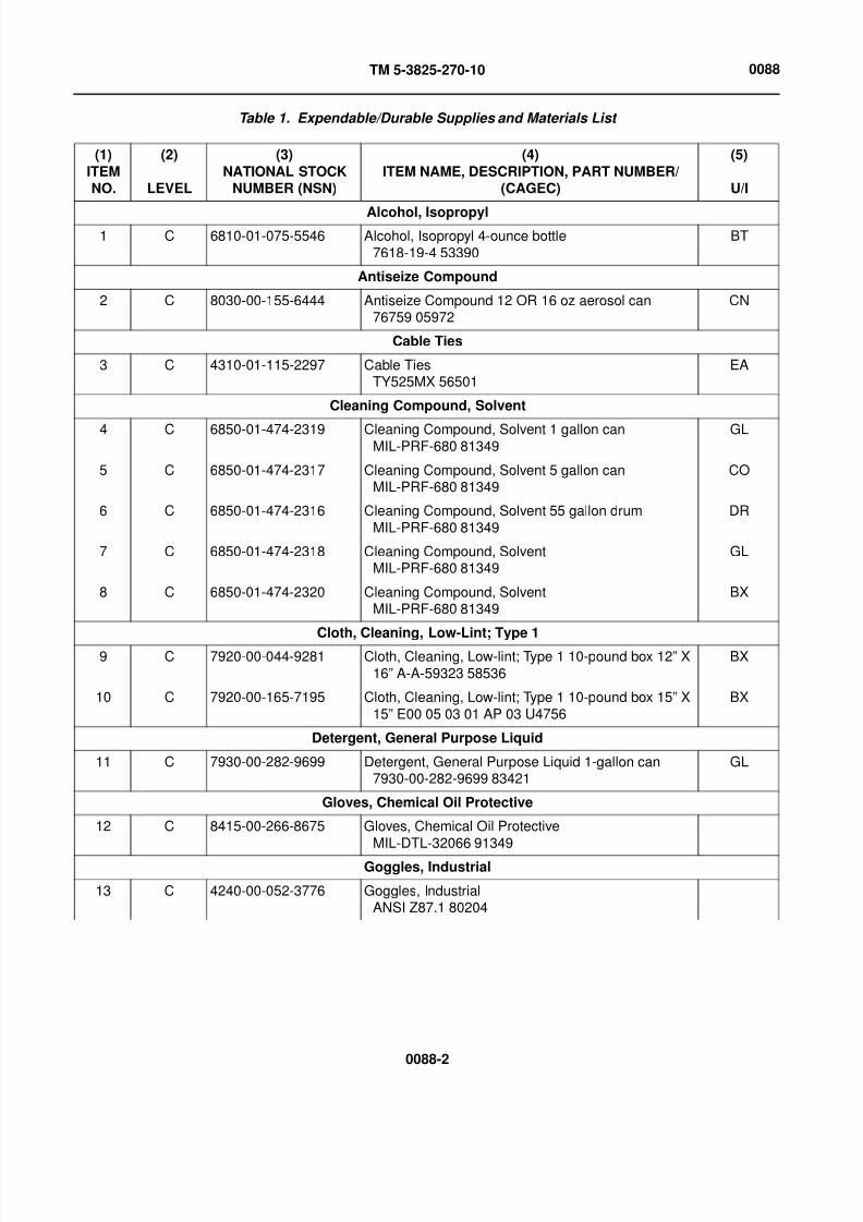
8/6/2019 TM 5-3825-270-10 ENGINEER MISSION MODULE WATER DISTRIBUTION
http://slidepdf.com/reader/full/tm-5-3825-270-10-engineer-mission-module-water-distribution 462/483
TM 5-3825-270-10
0088-2
0088
Table 1. Expendable/Durable Supplies and Materials List
(1)
ITEMNO.
(2)
LEVEL
(3)
NATIONAL STOCKNUMBER (NSN)
(4)
ITEM NAME, DESCRIPTION, PART NUMBER/(CAGEC)
(5)
U/I
Alcohol, Isopropyl1 C 6810-01-075-5546 Alcohol, Isopropyl 4-ounce bottle
7618-19-4 53390
BT
Antiseize Compound
2 C 8030-00-155-6444 Antiseize Compound 12 OR 16 oz aerosol can76759 05972
CN
Cable Ties
3 C 4310-01-115-2297 Cable TiesTY525MX 56501
EA
Cleaning Compound, Solvent
4 C 6850-01-474-2319 Cleaning Compound, Solvent 1 gallon canMIL-PRF-680 81349
GL
5 C 6850-01-474-2317 Cleaning Compound, Solvent 5 gallon canMIL-PRF-680 81349
CO
6 C 6850-01-474-2316 Cleaning Compound, Solvent 55 gallon drum
MIL-PRF-680 81349
DR
7 C 6850-01-474-2318 Cleaning Compound, SolventMIL-PRF-680 81349
GL
8 C 6850-01-474-2320 Cleaning Compound, SolventMIL-PRF-680 81349
BX
Cloth, Cleaning, Low-Lint; Type 1
9 C 7920-00-044-9281 Cloth, Cleaning, Low-lint; Type 1 10-pound box 12” X
16” A-A-59323 58536
BX
10 C 7920-00-165-7195 Cloth, Cleaning, Low-lint; Type 1 10-pound box 15” X
15” E00 05 03 01 AP 03 U4756
BX
Detergent, General Purpose Liquid
11 C 7930-00-282-9699 Detergent, General Purpose Liquid 1-gallon can7930-00-282-9699 83421
GL
Gloves, Chemical Oil Protective
12 C 8415-00-266-8675 Gloves, Chemical Oil Protective
MIL-DTL-32066 91349
Goggles, Industrial
13 C 4240-00-052-3776 Goggles, IndustrialANSI Z87.1 80204

8/6/2019 TM 5-3825-270-10 ENGINEER MISSION MODULE WATER DISTRIBUTION
http://slidepdf.com/reader/full/tm-5-3825-270-10-engineer-mission-module-water-distribution 463/483
TM 5-3825-270-10
0088-3
0
Grease, Automotive and Artillery (GAA) (MIL-PRF-10924)
14 C 9150-01-197-7688 Grease, Automotive and Artillery (GAA)(MIL-PRF-10924) 2 1/4-ounce tube
M-10924-A 81349
TU
15 C 9150-01-197-7693 Grease, Automotive and Artillery (GAA)(MIL-PRF-10924) 14-ounce cartridge
M-10924-B 81349
CA
16 C 9150-01-197-7689 Grease, Automotive and Artillery (GAA)
(MIL-PRF-10924) 6 1/2-pound canM-10924-D 81349
CN
17 C 9150-01-197-7692 Grease, Automotive and Artillery (GAA)
(MIL-PRF-10924) 35-pound canM-10924-E 81349
CN
18 C 9150-01-197-7691 Grease, Automotive and Artillery (GAA)
(MIL-PRF-10924) 120-pound drumM-10924-F 81349
DR
Oil, Lubricating, Internal Combustion Engine, Tactical Service OE/HDO 15W40 (MIL-PRF-2104)
19 C 9150-01-152-4117 Oil, Lubricating, Internal Combustion Engine, TacticalService OE/HDO 15W40 (MIL-PRF-2104) 1-quartcan
M2104-1-15W40 81349
QT
20 C 9150-01-421-1427 Oil, Lubricating, Internal Combustion Engine, Tactical
Service OE/HDO 15W40 (MIL-PRF-2104) 24-quartbox
MIL-PRF-2104 81349
QT
21 C 9150-01-421-1424 Oil, Lubricating, Internal Combustion Engine, TacticalService OE/HDO 15W40 (MIL-PRF-2104) 5-gallon
canMIL-PRF-2104 81349
CN
22 C 9150-01-421-1432 Oil, Lubricating, Internal Combustion Engine, Tactical
Service OE/HDO 15W40 (MIL-PRF-2104) 55-gallondrum
MIL-PRF-2104 81349
DR
Oil, Lubricating, OE/HDO-30 (MIL-PRF-2104)23 C 9150-00-188-9858 Oil, Lubricating, OE/HDO-30 (MIL-PRF-2104)
5-gallon canMIL-PRF-2104 81349
CN
24 C 9150-00-189-6729 Oil, Lubricating, OE/HDO-30 (MIL-PRF-2104)
55-gallon drumMIL-PRF-2104 81349
DR
Table 1. Expendable/Durable Supplies and Materials List (Continued)
(1)ITEM
NO.
(2)
LEVEL
(3)NATIONAL STOCK
NUMBER (NSN)
(4)ITEM NAME, DESCRIPTION, PART NUMBER/
(CAGEC)
(5)
U/I

8/6/2019 TM 5-3825-270-10 ENGINEER MISSION MODULE WATER DISTRIBUTION
http://slidepdf.com/reader/full/tm-5-3825-270-10-engineer-mission-module-water-distribution 464/483
TM 5-3825-270-10
0088-4
0088
END OF WORK PACKAGE
Oil, Lubricating, OE/HDO 10 (MIL-PRF-2104)25 C 9150-00-189-6727 Oil, Lubricating, OE/HDO 10 1-quart can
MIL-PRF-2104 81349QT
26 C 9150-00-186-6668 Oil, Lubricating, OE/HDO 10 5-gallon can
MIL-PRF-2104 81349
CN
27 C 9150-00-191-2772 Oil, Lubricating, OE/HDO 10 55-gallon drum
MIL-PRF-2104 81349
DR
Plug, Ear
28 C 6515-00-137-6345 Plug, Ear
4-375 89875
Rag, Wiping
29 C 7920-00-205-1711 Rag, Wiping 50 pound bale
7920-00-205-1711 80244
BE
Soil Stabilization Additive (Soiltac)
30 C 6850-01-519-4708 Soil Stabilization Additive (Soiltac) 275 gallon
SOILTAC-275-GALLON IBC 3FTH5
DR
Tape, Duct
31 C 5640-01-542-7337 Tape, Duct
76035A73 39428
RO
Table 1. Expendable/Durable Supplies and Materials List (Continued)
(1)
ITEMNO.
(2)
LEVEL
(3)
NATIONAL STOCKNUMBER (NSN)
(4)
ITEM NAME, DESCRIPTION, PART NUMBER/(CAGEC)
(5)
U/I

8/6/2019 TM 5-3825-270-10 ENGINEER MISSION MODULE WATER DISTRIBUTION
http://slidepdf.com/reader/full/tm-5-3825-270-10-engineer-mission-module-water-distribution 465/483
OPERATOR MAINTENANCEFO1 DATA PLATE
FO1 DATA PLATE
The following diagram is the Data Plate for the EMM - WD. Data Plate. (FO-1)
END OF WORK PACKAGE
TM 5-3825-270-10 0089
0089-1/2 blank

8/6/2019 TM 5-3825-270-10 ENGINEER MISSION MODULE WATER DISTRIBUTION
http://slidepdf.com/reader/full/tm-5-3825-270-10-engineer-mission-module-water-distribution 466/483
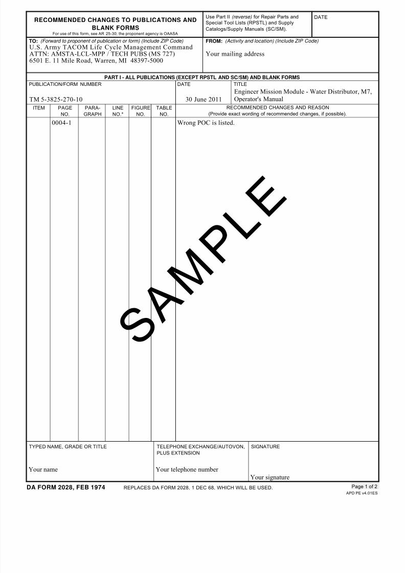
8/6/2019 TM 5-3825-270-10 ENGINEER MISSION MODULE WATER DISTRIBUTION
http://slidepdf.com/reader/full/tm-5-3825-270-10-engineer-mission-module-water-distribution 467/483
Your telephone number Your name
TM 5-3825-270-10
Your mailing addressU.S. Army TACOM Life Cycle Management CommandATTN: AMSTA-LCL-MPP / TECH PUBS (MS 727)6501 E. 11 Mile Road, Warren, MI 48397-5000
30 June 2011
Engineer Mission Module - Water Distributor, M7,
Operator's Manual
Your signature
0004-1 Wrong POC is listed.
For use of this form, see AR 25-30; the proponent agency is OAASA
TELEPHONE EXCHANGE/AUTOVON,
PLUS EXTENSION
TYPED NAME, GRADE OR TITLE
PUBLICATION/FORM NUMBER
DATE
TO:
REPLACES DA FORM 2028, 1 DEC 68, WHICH WILL BE USED.
PARA-
GRAPH
(Forward to proponent of publication or form) (Include ZIP Code)
PART I - ALL PUBLICATIONS (EXCEPT RPSTL AND SC/SM) AND BLANK FORMS
DATE TITLE
PAGE
NO.
ITEM LINE
NO.*
FIGURE
NO.
TABLE
NO.
RECOMMENDED CHANGES AND REASON
(Provide exact wording of recommended changes, if possible).
SIGNATURE
DA FORM 2028, FEB 1974APD PE v4.01ES
Page 1 of 2
Use Part II (reverse) for Repair Parts and
FROM: (Activity and location) (Include ZIP Code)
Special Tool Lists (RPSTL) and Supply
Catalogs/Supply Manuals (SC/SM).
RECOMMENDED CHANGES TO PUBLICATIONS AND
BLANK FORMS
S A M P L E

8/6/2019 TM 5-3825-270-10 ENGINEER MISSION MODULE WATER DISTRIBUTION
http://slidepdf.com/reader/full/tm-5-3825-270-10-engineer-mission-module-water-distribution 468/483
U.S. Army TACOM Life Cycle Management CommandATTN: AMSTA-LCL-MPP / TECH PUBS (MS 727)
6501 E. 11 Mile Road, Warren, MI 48397-5000
Your nameYour telephone number
Engineer Mission Module - Water Distributor, M7,Operator's Manual
TM 5-3825-270-10
30 June 2011
Your signature
TYPED NAME, GRADE OR TITLE
PART III - REMARKS
TITLEPUBLICATION NUMBER DATE
RECOMMENDED ACTION
PART II - REPAIR PARTS AND SPECIAL TOOL LISTS AND SUPPLY CATALOGS/SUPPLY MANUALS
DATE
SIGNATURE
Page 2 of 2
TO: (Forward direct to addressee listed in publication) FROM: (Activity and location) (Include ZIP Code)
PAGE
NO.
COLM
NO.
LINE
NO.
NATIONAL STOCK
NUMBER
REFERENCE
NO.
FIGURE
NO.
ITEM
NO.
TOTAL NO.
OF MAJOR
ITEMS
SUPPORTED
(Any general remarks or recommendations, or suggestions for improvement of publications and blank forms. Additional blank sheets may be used if more space is needed.)
TELEPHONE EXCHANGE/AUTOVON,PLUS EXTENSION
DA FORM 2028, FEB 1974
S A M P L E

8/6/2019 TM 5-3825-270-10 ENGINEER MISSION MODULE WATER DISTRIBUTION
http://slidepdf.com/reader/full/tm-5-3825-270-10-engineer-mission-module-water-distribution 469/483
TM 5-3825-270-10
U.S. Army TACOM Life Cycle Management CommandATTN: AMSTA-LCL-MPP / TECH PUBS (MS 727)6501 E. 11 Mile Road, Warren, MI 48397-5000
30 June 2011
Engineer Mission Module - Water Distributor, M7,
Operator's Manual
For use of this form, see AR 25-30; the proponent agency is OAASA
TELEPHONE EXCHANGE/AUTOVON,
PLUS EXTENSION
TYPED NAME, GRADE OR TITLE
PUBLICATION/FORM NUMBER
DATE
TO:
REPLACES DA FORM 2028, 1 DEC 68, WHICH WILL BE USED.
PARA-
GRAPH
(Forward to proponent of publication or form) (Include ZIP Code)
PART I - ALL PUBLICATIONS (EXCEPT RPSTL AND SC/SM) AND BLANK FORMS
DATE TITLE
PAGE
NO.
ITEM LINE
NO.*
FIGURE
NO.
TABLE
NO.
RECOMMENDED CHANGES AND REASON
(Provide exact wording of recommended changes, if possible).
SIGNATURE
DA FORM 2028, FEB 1974APD PE v4.01ES
Page 1 of 2
Use Part II (reverse) for Repair Parts and
FROM: (Activity and location) (Include ZIP Code)
Special Tool Lists (RPSTL) and Supply
Catalogs/Supply Manuals (SC/SM).
RECOMMENDED CHANGES TO PUBLICATIONS AND
BLANK FORMS
8/6/2019 TM 5-3825-270-10 ENGINEER MISSION MODULE WATER DISTRIBUTION
http://slidepdf.com/reader/full/tm-5-3825-270-10-engineer-mission-module-water-distribution 470/483
U.S. Army TACOM Life Cycle Management CommandATTN: AMSTA-LCL-MPP / TECH PUBS (MS 727)
6501 E. 11 Mile Road, Warren, MI 48397-5000
Engineer Mission Module - Water Distributor, M7,Operator's Manual
TM 5-3825-270-10
30 June 2011
TYPED NAME, GRADE OR TITLE
PART III - REMARKS
TITLEPUBLICATION NUMBER DATE
RECOMMENDED ACTION
PART II - REPAIR PARTS AND SPECIAL TOOL LISTS AND SUPPLY CATALOGS/SUPPLY MANUALS
DATE
SIGNATURE
Page 2 of 2
TO: (Forward direct to addressee listed in publication) FROM: (Activity and location) (Include ZIP Code)
PAGE
NO.
COLM
NO.
LINE
NO.
NATIONAL STOCK
NUMBER
REFERENCE
NO.
FIGURE
NO.
ITEM
NO.
TOTAL NO.
OF MAJOR
ITEMS
SUPPORTED
(Any general remarks or recommendations, or suggestions for improvement of publications and blank forms. Additional blank sheets may be used if more space is needed.)
TELEPHONE EXCHANGE/AUTOVON,PLUS EXTENSION
DA FORM 2028, FEB 1974
8/6/2019 TM 5-3825-270-10 ENGINEER MISSION MODULE WATER DISTRIBUTION
http://slidepdf.com/reader/full/tm-5-3825-270-10-engineer-mission-module-water-distribution 471/483
TM 5-3825-270-10
U.S. Army TACOM Life Cycle Management CommandATTN: AMSTA-LCL-MPP / TECH PUBS (MS 727)6501 E. 11 Mile Road, Warren, MI 48397-5000
30 June 2011
Engineer Mission Module - Water Distributor, M7,
Operator's Manual
For use of this form, see AR 25-30; the proponent agency is OAASA
TELEPHONE EXCHANGE/AUTOVON,
PLUS EXTENSION
TYPED NAME, GRADE OR TITLE
PUBLICATION/FORM NUMBER
DATE
TO:
REPLACES DA FORM 2028, 1 DEC 68, WHICH WILL BE USED.
PARA-
GRAPH
(Forward to proponent of publication or form) (Include ZIP Code)
PART I - ALL PUBLICATIONS (EXCEPT RPSTL AND SC/SM) AND BLANK FORMS
DATE TITLE
PAGE
NO.
ITEM LINE
NO.*
FIGURE
NO.
TABLE
NO.
RECOMMENDED CHANGES AND REASON
(Provide exact wording of recommended changes, if possible).
SIGNATURE
DA FORM 2028, FEB 1974APD PE v4.01ES
Page 1 of 2
Use Part II (reverse) for Repair Parts and
FROM: (Activity and location) (Include ZIP Code)
Special Tool Lists (RPSTL) and Supply
Catalogs/Supply Manuals (SC/SM).
RECOMMENDED CHANGES TO PUBLICATIONS AND
BLANK FORMS

8/6/2019 TM 5-3825-270-10 ENGINEER MISSION MODULE WATER DISTRIBUTION
http://slidepdf.com/reader/full/tm-5-3825-270-10-engineer-mission-module-water-distribution 472/483
U.S. Army TACOM Life Cycle Management CommandATTN: AMSTA-LCL-MPP / TECH PUBS (MS 727)
6501 E. 11 Mile Road, Warren, MI 48397-5000
Engineer Mission Module - Water Distributor, M7,Operator's Manual
TM 5-3825-270-10
30 June 2011
TYPED NAME, GRADE OR TITLE
PART III - REMARKS
TITLEPUBLICATION NUMBER DATE
RECOMMENDED ACTION
PART II - REPAIR PARTS AND SPECIAL TOOL LISTS AND SUPPLY CATALOGS/SUPPLY MANUALS
DATE
SIGNATURE
Page 2 of 2
TO: (Forward direct to addressee listed in publication) FROM: (Activity and location) (Include ZIP Code)
PAGE
NO.
COLM
NO.
LINE
NO.
NATIONAL STOCK
NUMBER
REFERENCE
NO.
FIGURE
NO.
ITEM
NO.
TOTAL NO.
OF MAJOR
ITEMS
SUPPORTED
(Any general remarks or recommendations, or suggestions for improvement of publications and blank forms. Additional blank sheets may be used if more space is needed.)
TELEPHONE EXCHANGE/AUTOVON,PLUS EXTENSION
DA FORM 2028, FEB 1974

8/6/2019 TM 5-3825-270-10 ENGINEER MISSION MODULE WATER DISTRIBUTION
http://slidepdf.com/reader/full/tm-5-3825-270-10-engineer-mission-module-water-distribution 473/483
TM 5-3825-270-10
U.S. Army TACOM Life Cycle Management CommandATTN: AMSTA-LCL-MPP / TECH PUBS (MS 727)6501 E. 11 Mile Road, Warren, MI 48397-5000
30 June 2011
Engineer Mission Module - Water Distributor, M7,
Operator's Manual
For use of this form, see AR 25-30; the proponent agency is OAASA
TELEPHONE EXCHANGE/AUTOVON,
PLUS EXTENSION
TYPED NAME, GRADE OR TITLE
PUBLICATION/FORM NUMBER
DATE
TO:
REPLACES DA FORM 2028, 1 DEC 68, WHICH WILL BE USED.
PARA-
GRAPH
(Forward to proponent of publication or form) (Include ZIP Code)
PART I - ALL PUBLICATIONS (EXCEPT RPSTL AND SC/SM) AND BLANK FORMS
DATE TITLE
PAGE
NO.
ITEM LINE
NO.*
FIGURE
NO.
TABLE
NO.
RECOMMENDED CHANGES AND REASON
(Provide exact wording of recommended changes, if possible).
SIGNATURE
DA FORM 2028, FEB 1974APD PE v4.01ES
Page 1 of 2
Use Part II (reverse) for Repair Parts and
FROM: (Activity and location) (Include ZIP Code)
Special Tool Lists (RPSTL) and Supply
Catalogs/Supply Manuals (SC/SM).
RECOMMENDED CHANGES TO PUBLICATIONS AND
BLANK FORMS

8/6/2019 TM 5-3825-270-10 ENGINEER MISSION MODULE WATER DISTRIBUTION
http://slidepdf.com/reader/full/tm-5-3825-270-10-engineer-mission-module-water-distribution 474/483
U.S. Army TACOM Life Cycle Management CommandATTN: AMSTA-LCL-MPP / TECH PUBS (MS 727)
6501 E. 11 Mile Road, Warren, MI 48397-5000
Engineer Mission Module - Water Distributor, M7,Operator's Manual
TM 5-3825-270-10
30 June 2011
TYPED NAME, GRADE OR TITLE
PART III - REMARKS
TITLEPUBLICATION NUMBER DATE
RECOMMENDED ACTION
PART II - REPAIR PARTS AND SPECIAL TOOL LISTS AND SUPPLY CATALOGS/SUPPLY MANUALS
DATE
SIGNATURE
Page 2 of 2
TO: (Forward direct to addressee listed in publication) FROM: (Activity and location) (Include ZIP Code)
PAGE
NO.
COLM
NO.
LINE
NO.
NATIONAL STOCK
NUMBER
REFERENCE
NO.
FIGURE
NO.
ITEM
NO.
TOTAL NO.
OF MAJOR
ITEMS
SUPPORTED
(Any general remarks or recommendations, or suggestions for improvement of publications and blank forms. Additional blank sheets may be used if more space is needed.)
TELEPHONE EXCHANGE/AUTOVON,PLUS EXTENSION
DA FORM 2028, FEB 1974

8/6/2019 TM 5-3825-270-10 ENGINEER MISSION MODULE WATER DISTRIBUTION
http://slidepdf.com/reader/full/tm-5-3825-270-10-engineer-mission-module-water-distribution 475/483
TM 5-3825-270-10
U.S. Army TACOM Life Cycle Management CommandATTN: AMSTA-LCL-MPP / TECH PUBS (MS 727)6501 E. 11 Mile Road, Warren, MI 48397-5000
30 June 2011
Engineer Mission Module - Water Distributor, M7,
Operator's Manual
For use of this form, see AR 25-30; the proponent agency is OAASA
TELEPHONE EXCHANGE/AUTOVON,
PLUS EXTENSION
TYPED NAME, GRADE OR TITLE
PUBLICATION/FORM NUMBER
DATE
TO:
REPLACES DA FORM 2028, 1 DEC 68, WHICH WILL BE USED.
PARA-
GRAPH
(Forward to proponent of publication or form) (Include ZIP Code)
PART I - ALL PUBLICATIONS (EXCEPT RPSTL AND SC/SM) AND BLANK FORMS
DATE TITLE
PAGE
NO.
ITEM LINE
NO.*
FIGURE
NO.
TABLE
NO.
RECOMMENDED CHANGES AND REASON
(Provide exact wording of recommended changes, if possible).
SIGNATURE
DA FORM 2028, FEB 1974APD PE v4.01ES
Page 1 of 2
Use Part II (reverse) for Repair Parts and
FROM: (Activity and location) (Include ZIP Code)
Special Tool Lists (RPSTL) and Supply
Catalogs/Supply Manuals (SC/SM).
RECOMMENDED CHANGES TO PUBLICATIONS AND
BLANK FORMS

8/6/2019 TM 5-3825-270-10 ENGINEER MISSION MODULE WATER DISTRIBUTION
http://slidepdf.com/reader/full/tm-5-3825-270-10-engineer-mission-module-water-distribution 476/483
U.S. Army TACOM Life Cycle Management CommandATTN: AMSTA-LCL-MPP / TECH PUBS (MS 727)
6501 E. 11 Mile Road, Warren, MI 48397-5000
Engineer Mission Module - Water Distributor, M7,Operator's Manual
TM 5-3825-270-10
30 June 2011
TYPED NAME, GRADE OR TITLE
PART III - REMARKS
TITLEPUBLICATION NUMBER DATE
RECOMMENDED ACTION
PART II - REPAIR PARTS AND SPECIAL TOOL LISTS AND SUPPLY CATALOGS/SUPPLY MANUALS
DATE
SIGNATURE
Page 2 of 2
TO: (Forward direct to addressee listed in publication) FROM: (Activity and location) (Include ZIP Code)
PAGE
NO.
COLM
NO.
LINE
NO.
NATIONAL STOCK
NUMBER
REFERENCE
NO.
FIGURE
NO.
ITEM
NO.
TOTAL NO.
OF MAJOR
ITEMS
SUPPORTED
(Any general remarks or recommendations, or suggestions for improvement of publications and blank forms. Additional blank sheets may be used if more space is needed.)
TELEPHONE EXCHANGE/AUTOVON,PLUS EXTENSION
DA FORM 2028, FEB 1974

8/6/2019 TM 5-3825-270-10 ENGINEER MISSION MODULE WATER DISTRIBUTION
http://slidepdf.com/reader/full/tm-5-3825-270-10-engineer-mission-module-water-distribution 477/483
TM 5-3825-270-10
U.S. Army TACOM Life Cycle Management CommandATTN: AMSTA-LCL-MPP / TECH PUBS (MS 727)6501 E. 11 Mile Road, Warren, MI 48397-5000
30 June 2011
Engineer Mission Module - Water Distributor, M7,
Operator's Manual
For use of this form, see AR 25-30; the proponent agency is OAASA
TELEPHONE EXCHANGE/AUTOVON,
PLUS EXTENSION
TYPED NAME, GRADE OR TITLE
PUBLICATION/FORM NUMBER
DATE
TO:
REPLACES DA FORM 2028, 1 DEC 68, WHICH WILL BE USED.
PARA-
GRAPH
(Forward to proponent of publication or form) (Include ZIP Code)
PART I - ALL PUBLICATIONS (EXCEPT RPSTL AND SC/SM) AND BLANK FORMS
DATE TITLE
PAGE
NO.
ITEM LINE
NO.*
FIGURE
NO.
TABLE
NO.
RECOMMENDED CHANGES AND REASON
(Provide exact wording of recommended changes, if possible).
SIGNATURE
DA FORM 2028, FEB 1974APD PE v4.01ES
Page 1 of 2
Use Part II (reverse) for Repair Parts and
FROM: (Activity and location) (Include ZIP Code)
Special Tool Lists (RPSTL) and Supply
Catalogs/Supply Manuals (SC/SM).
RECOMMENDED CHANGES TO PUBLICATIONS AND
BLANK FORMS

8/6/2019 TM 5-3825-270-10 ENGINEER MISSION MODULE WATER DISTRIBUTION
http://slidepdf.com/reader/full/tm-5-3825-270-10-engineer-mission-module-water-distribution 478/483
U.S. Army TACOM Life Cycle Management CommandATTN: AMSTA-LCL-MPP / TECH PUBS (MS 727)
6501 E. 11 Mile Road, Warren, MI 48397-5000
Engineer Mission Module - Water Distributor, M7,Operator's Manual
TM 5-3825-270-10
30 June 2011
TYPED NAME, GRADE OR TITLE
PART III - REMARKS
TITLEPUBLICATION NUMBER DATE
RECOMMENDED ACTION
PART II - REPAIR PARTS AND SPECIAL TOOL LISTS AND SUPPLY CATALOGS/SUPPLY MANUALS
DATE
SIGNATURE
Page 2 of 2
TO: (Forward direct to addressee listed in publication) FROM: (Activity and location) (Include ZIP Code)
PAGE
NO.
COLM
NO.
LINE
NO.
NATIONAL STOCK
NUMBER
REFERENCE
NO.
FIGURE
NO.
ITEM
NO.
TOTAL NO.
OF MAJOR
ITEMS
SUPPORTED
(Any general remarks or recommendations, or suggestions for improvement of publications and blank forms. Additional blank sheets may be used if more space is needed.)
TELEPHONE EXCHANGE/AUTOVON,PLUS EXTENSION
DA FORM 2028, FEB 1974

8/6/2019 TM 5-3825-270-10 ENGINEER MISSION MODULE WATER DISTRIBUTION
http://slidepdf.com/reader/full/tm-5-3825-270-10-engineer-mission-module-water-distribution 479/483
- - - - - - - - - - - - - - - - - - - - - - - - - - - - - - - - - - - - -
- - - - - - - - - - - - - - - - - - - - - - - - - - - - - - - - - - - - -
- - - - - - - - - - - - - - - - - - - - - - - - - - - - - - - - - - - - -
- - - - - - - - - - - - - - - - - - - - - - - - - - - - - - - - - - - - -
By Order of the Secretary of the Army:
MARTIN E. DEMPSEY
General, United States Army
Chief of Staff
Official:
- - - - - - - - - - - - - - - - - - - - - - - - - - - - - - - - - - - - -
- - - - - - - - - - - - - - - - - - - - - - - - - - - - - - - - - - - - -
JOYCE E. MORROW
Administrative Assistant to the Secretary of the Army
1113102
DISTRIBUTION: To be distributed in accordance with the initial distribution requirements for IDN: 257874,
requirements for TM 5-3825-270-10.

8/6/2019 TM 5-3825-270-10 ENGINEER MISSION MODULE WATER DISTRIBUTION
http://slidepdf.com/reader/full/tm-5-3825-270-10-engineer-mission-module-water-distribution 480/483
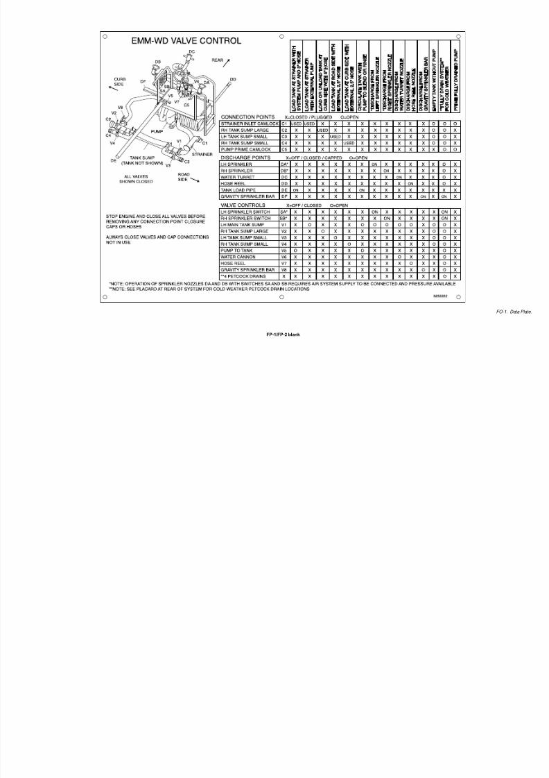
8/6/2019 TM 5-3825-270-10 ENGINEER MISSION MODULE WATER DISTRIBUTION
http://slidepdf.com/reader/full/tm-5-3825-270-10-engineer-mission-module-water-distribution 481/483
FO-1. D
FP-1/FP-2 blank

8/6/2019 TM 5-3825-270-10 ENGINEER MISSION MODULE WATER DISTRIBUTION
http://slidepdf.com/reader/full/tm-5-3825-270-10-engineer-mission-module-water-distribution 482/483

8/6/2019 TM 5-3825-270-10 ENGINEER MISSION MODULE WATER DISTRIBUTION
http://slidepdf.com/reader/full/tm-5-3825-270-10-engineer-mission-module-water-distribution 483/483


![Med · 270 342 [(+72) (270+72) 472 (270+72 [(+72) tztžU +130) (+102)] (+130) 520 (270+250) 1270+102 752 (270+102 (+480) 750 270+480) 852 (270+102 (270+102](https://img.dokumen.tips/doc/110x75/5fb23750d464052f95224679/med-270-342-72-27072-472-27072-72-tztu-130-102-130-520-270250.jpg)