Embed Size (px)
Citation preview

3 Series 1 Series 120 Volt Heated Cabinets USer ManUal
InterMetro Industries CorporationWilkes-Barre, PA 18705570-825-2741 www.metro.com
L01-430 Rev. C 2/09
Information and specifications are subject to change without notice. Please confirm at time of order.
TM
Metro Heated Cabinets are for Hot Food Holding applications only
1 Series
120
volt
3 Series

See Data Plate forElectrical Specifications
MOISTURE
Com
bina
tion
Mod
ule
Hol
ding
Mod
ule
See Data Plate forElectrical SpecificationsHOLDING
C05-961
Com
bina
tion
Mod
ule
See Data Plate forElectrical Specifications
MOISTURE
Pro
ofin
gM
odul
e
See Data Plate forElectrical Specifications
MOISTURE
C5-PM- 0001000
C05-963
PROOFING
HOLDING INSTRUCTIONS
BASIC CABINET SETUP
CAUTION
A. Refer to DATA PLATE for electrical requirements. Cabinets rated at 120V 2000watts must be plugged into a 125 VAC 20 amp receptacle and must be used on anindividual branch circuit. Cabinets rated at 120V 1440 watts must be plugged intoeither a 15 amp or 20 amp 125 VAC receptacle. DO NOT MODIFY CORD PLUG.B. With POWER switch OFF, plug into 125 VAC grounded receptacle.C. Fill water pan to top with clean HOT tap water for Proofing or if moisture is desiredfor Holding. Check water level every 3 hours (2 hours when Proofing) and refill withclean HOT tap water as necessary. Water pan does not have to be filled for Holding.Proofing requires water pan to be filled.
1) Set Combination Module switch to HOLD2) Set POWER switch to the ON position.3) Set TEMPERATURE control to 10.4) Set MOISTURE control to 10 (or desired level) on Moisture Module Only.5) Pre-heat cabinet until desired temperature is reached (typical heat-up time from72˚(22˚C) ambient to 160˚(71˚C) is approximately 45 minutes).6) Re-set TEMPERATURE control and adjust as necessary to reach desired temperature (setting 6-8 is typical for 150˚(66˚C) to 160˚ (71˚C)). Power indicator light will turn on and off as the heat thermostat cycles.
1) Set Combination Module switch to PROOF2) Set POWER switch to the ON position.3) Set TEMPERATURE control to 2.4) Set MOISTURE control to 10.5) Pre-heat cabinet until desired temperature and humidity is reached (typical heat-up time from 72˚(22˚C) ambient to 95˚(35˚C) and 95% relative humidity is approximately 30 minutes).6) Adjust settings as necessary to reach desired temperature and humidity levels.Power indicator lights will turn on and off as the heat and moisture thermostats cycle.
3 & 1 SERIESOPERATING INSTRUCTIONS
Breads
Biscuit, Buttermilk Mini 175˚ (79˚C)Croissants, Sliced 155˚ (68˚C)French Toast, Thin Slice 175˚ (79˚C)Waffles, Original 175˚ (79˚C)Pancakes 175˚ (79˚C)Pizza 175˚ (79˚C)Rolls 175˚ (79˚C)Dough (Proofing) 90-100˚ (32-38˚C)
MeatsPrime Rib 175˚ (79˚C)Hamburgers 180˚ (82˚C)Hot Dogs 170˚ (77˚C)Roast Beef 175˚ (79˚C)Roast Pork 175˚ (79˚C)Ribs (Pork Spareribs) 175˚ (79˚C)Poultry
Chicken, Boneless, Skinless 175˚ (79˚C)Chicken, Thigh, Baked, Fried 175˚ (79˚C)Chicken, Full Breast 175˚ (79˚C)Chicken, Drum, Baked, Fried 175˚ (79˚C)Chicken, Leg 175˚ (79˚C)Chicken, Fried Full Breast 175˚ (79˚C)Chicken, Fried Thigh 175˚ (79˚C)Chicken, Fried Drum 175˚ (79˚C)Chicken, Fried Boneless Skinless 175˚ (79˚C)Chicken, Whole Roasted 170˚ (77˚C)Turkey 175˚ (79˚C)Vegetables
Broccoli, Spears 175˚ (79˚C)Carrots, Sliced, Crinkled 175˚ (79˚C)Cauliflower, Clusters IQF 175˚ (79˚C)Corn on the Cob 180˚ (82˚C)Mixed Vegetables 175˚ (79˚C)
Fry, Regular 3/8" 195˚ (91˚C)Potatoes, Mashed 175˚ (79˚C)Potatoes, Baked 180˚ (82˚C)Potatoes, Scalloped 175˚ (79˚C)
Starches
Pasta, Elbow Macaroni 180˚ (82˚C)Rice 180˚ (82˚C)Lasagna, Meat Sauce & Cheese 185˚ (85˚C)Beans 175˚ (79˚C)
FishFish, Baked (Cod Loin) IQF 170˚ (77˚C)Fish, Batter Dipped 175˚ (79˚C)
Developed in conjunction with the Center for Food Innovation (CFI), Penn State University
F O O D S E T T I N G S G U I D E
®
2 3 1
2 3
2 3 14
42 3
• WATER PAN MUST BE IN PLACE DURING MODULE OPERATION.
• UNPLUG CABINET FROM WALL AND ALLOW CABINET (ANDWATER) TO COOL BEFORE CLEANING OR SERVICING.
• DO NOT SPRAY OR POUR WATER ON THE MODULE WHENCLEANING AND DO NOT IMMERSE THE MODULE IN WATER.WIPE WITH A DAMP CLOTH AND DRY WITH A TOWEL.
• KEEP CABINET AND MODULE CLEAN. ACCUMULATION OFGREASE AND OTHER DRIPPINGS MAY IGNITE.
Moi
stur
eH
oldi
ngM
odul
e
See Data Plate forElectrical Specifications
MOISTURE
C5-PM- 0001000
C05-963
MOISTUREHOLDING
PROOFING INSTRUCTIONS
2 3 4
Moi
stur
eH
oldi
ngM
odul
e
See Data Plate forElectrical Specifications
MOISTURE
120
volt

�
Table of ConTenTsSection Page
i. Basicoperatingguidelines......insideFrontcover
ii. Safetyinformation.............................................. �
iii. identifyingYourcabinet.................................... 2
iV. installation&Set-up........................................... 3
V. ProductFeatures............................................... 7
Vi. operatinginstructions....................................... 8
Vii. care&Maintenance..........................................�0
Viii. Basictroubleshooting.......................................��
iX. Service&ReplacementParts............................�3
X. Warranty..................................................24,25-26
safeTY InfoRMaTIon WARNING: Followallfoodsafetyguidelines.Pre-heatthecabinettothedesiredtemperaturebeforeplacing
cooked,hotfoodintothecabinet.thisisnotare-thermalizingcabinet.Foodmustbeattheappropriatetemperaturebeforebeingplacedintothiscabinet.Useafoodprobetocheckinternalfoodtemperature—thecabinettemperatureisnotnecessarilytheinternalfoodtemperature.
WARNING: onlyfactoryapprovedserviceagentsshouldattempttoservice,repairorreplaceelectricalcomponents,wiringorpowercord.
WARNING: Unplugthecabinetbeforecleaningorservicing.Donotwashthecabinetwithawaterjetorhighpressurewater.
WARNING: thiscabinetisforhotfoodholdingapplicationsonly.
CAUTION: Donotsprayorpourwaterintothemodule.tocleanthecabinet,wipewithadampclothanddrywithatowel.Useonlycleaningagentsapprovedforaluminum.
CAUTION: Waterdrippingontothefloorfromopendoorscanbeasliphazard.
120
volt

2
IDenTIfYInG YoUR CabIneT
PaRT nUMbeRInG
Forfuturereference,recordthecabinetmodelnumber&manufactureddatefoundonthedateplatelocatedatrearofcabinet.alsorecordthemoduleserialnumberlocatedinsidethecabinetonmoduletopright-handcorner.
Modelnumber:
cabinetmanufactureddate:
Moduleserialnumber:
Modulemanufactureddate:
Filloutandreturnthewarrantycardlocatedatthebackofthismanual.
C51SERIESCABINETC519—HFC—4A
caBinetnaMe
caBinettYPe�=Un-inSULateD
caBinetSiZe(HeigHt)9=FULL7=3/4
5=�/2
MoDULec=c5-cM2000,coMBo,2000W.H=c5-HM2000,HoLDing,2000W.P=c5-PM�500,PRooFeR,�440W.
a=acceSSoRieS
SLiDeSL=FiXeD,LiPLoaDU=aDJUStaBLe,UniVeRSaL4=FiXeDWiRe
DooRFc=FULLcLeaR
C53SERIESCABINETC539—HLDS—U—BUA
caBinetnaMecaBinettYPe3=inSULateD
caBinetSiZe(HeigHt)9=FULL7=3/4
5=�/2
MoDULec=c5-cM2000,coMBo,2000W.H=c5-HM2000,HoLDing,2000W.P=c5-PM�500,PRooFeR,�440W.HL=c5-HM�500,HoLDing,�440W.cL=c5-cM�500,coMBo,�440W.M=c5-MM2000,MoiStUReHoLDing,�20V-�990W.
a=acceSSoRieS
SLiDeSL=FiXeD,LiPLoaDU=aDJUStaBLe,UniVeRSaL4=FiXeDWiRe
DooR(S)FS=FULLSoLiDDS=DUtcHSoLiDFc=FULLcLeaRDc=DUtcHcLeaR
120
volt
PaneLcoLoRBg=Beige BLank=ReDBU=BLUe Sg=SagegY=gRaY gReenoR=oRange YL=YeLLoW
3
InsTallaTIon anD seT-UP�. checkforShippingDamage:checkthepackagingandcabinetforshippingdamageafterunloadingtheunit,
andafterremovingallthepackaging.
2. thereceiverofthisproductisresponsibleforfilingfreightdamageclaims.thisequipmentmustbeopenedimmediatelyforinspection.allvisibledamagemustbereportedtothefreightcompanywithin48hoursandmustbenotedonfreightbillatthetimeofdelivery.
3. concealeddamageisyourresponsibility—youmustadvisethecarrierofanylossordamagewithin�5daysafterreceiptofthecabinet.ifthereisdamage,retaintheoriginalpackagingforinspectors.
4. afterunpackingthecabinet,removealltapeandpackingmaterialfromtheinsideaswellasoutsideoftheunit.
5. anyprotectivecovers(plasticorpapersheet)onthesheetmetalorcleardoor,ifapplicable,mustalsoberemovedbeforeturningthecabineton.
WARNING:Only factory approved service agents should attempt to service, repair or replace electrical components, wiring or the power cord.
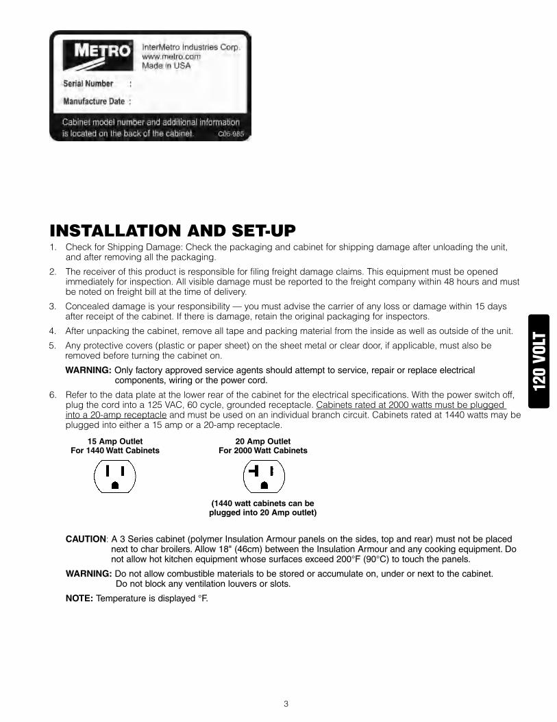
6. Refertothedataplateatthelowerrearofthecabinetfortheelectricalspecifications.Withthepowerswitchoff,plugthecordintoa�25Vac,60cycle,groundedreceptacle.cabinetsratedat2000wattsmustbepluggedintoa20-ampreceptacleandmustbeusedonanindividualbranchcircuit.cabinetsratedat�440wattsmaybepluggedintoeithera�5ampora20-ampreceptacle.
15AmpOutletFor1440WattCabinets
20AmpOutletFor2000WattCabinets
(1440wattcabinetscanbepluggedinto20Ampoutlet)
CAUTION:A 3 Series cabinet (polymer Insulation Armour panels on the sides, top and rear) must not be placed next to char broilers. Allow 18" (46cm) between the Insulation Armour and any cooking equipment. Do not allow hot kitchen equipment whose surfaces exceed 200°F (90°C) to touch the panels.
WARNING:Do not allow combustible materials to be stored or accumulate on, under or next to the cabinet. Do not block any ventilation louvers or slots.
NOTE:Temperature is displayed °F.
120
volt
4
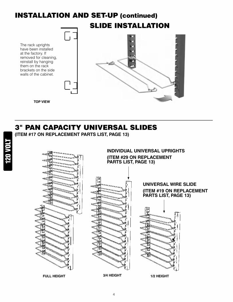
3" Pan CaPaCITY UnIVeRsal slIDes(ITEM#17ONREPLACEMENTPARTSLIST,PAGE13)
slIDe InsTallaTIon
therackuprightshavebeeninstalledatthefactory.ifremovedforcleaning,reinstallbyhangingthemontherackbracketsonthesidewallsofthecabinet.
InsTallaTIon anD seT-UP (continued)
TOPVIEW
FULLHEIGHT 3/4HEIGHT 1/2HEIGHT
UNIVERSALWIRESLIDE(ITEM#19ONREPLACEMENTPARTSLIST,PAGE13)
120
volt
INDIVIDUALUNIVERSALUPRIGHTS(ITEM#29ONREPLACEMENTPARTSLIST,PAGE13)

5
CoRReCT oRIenTaTIon of lIP loaDeD slIDes(ITEM#18ONREPLACEMENTPARTSLIST,PAGE13)
InsTallaTIon anD seT-UP (continued)
CoRReCT oRIenTaTIon of fIXeD WIRe slIDes(ITEM#16ONREPLACEMENTPARTSLIST,PAGE13)
FULLHEIGHT 3/4HEIGHT 1/2HEIGHT
FULLHEIGHT 3/4HEIGHT 1/2HEIGHT
120
volt
6
ReVeRsInG THe DooRsthedooronyourcabinetcanbereversedtoaccommodatearight-orleft-handopening.thecabinethasbeenshippedwiththehingesmountedontheright-handside.toreverse,followtheinstructionslistedbelow:
�. Withthedoorintheclosedposition,removethehingepinbydrivingitoutusingahammerandadrivepinorsmalldiameterscrewdriver.
2. oncethepinsareremovedgraspthedoorfirmlyandpullthelatchlever,thiswillreleasethedoor.Setthedoorasidebeingcarefulnottodamagethegasket.
3. Removethescrewsfromtheleftsideofthecabinetandsetaside.thenremovethecabinetmountedpartofthehingeandremounttotheleftsideofthecabinet.Putthescrewsremovedfromtheleftsideofthecabinetintotheremainingholesontherightsideofthecabinet.tightenallscrewsbeforeproceeding.
4. Relocatethelatchplate(s)fromtheleftsidetotherightbyremovingthetwomountingscrews.tightenallscrewsbeforeproceeding.
5. Rotatethedoor�80degreesandalignthedoormountedhingepartwiththecabinetmountedhingepartandtapthehingepinintoplacesothetopofthepinisflushwithtopofthecabinetmountedhingepart.invertthedoorlatchbyremovingtheblackplasticscrewcoversandremovethescrewsholdingthelatchinplace.
120
volt

7
PRoDUCT feaTURes•themodulehasbeenplacedat
thebaseofthecabinetforeasyaccessibilityandefficientoperation.
•clearly-markedcontrolpanelforeasyviewingallowsclimateadjustmentswithoutopeningthedoor.
•Removablewaterpan.
•cabinetdesignedwithdriptroughandcatchpantocontaincondensationdrippage.
•Fieldreversible,gasketeddoor.
•easypulladjustablemagneticdoorlatch.
•cordkeeperatrearofcabinet.
•allcomponents—door,module,slideracks—areremovabletopermitthorough,obstruction-freecleaning.
120
volt
8
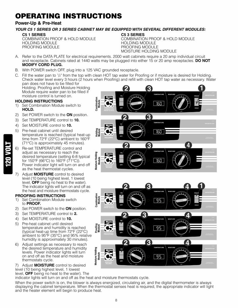
oPeRaTInG InsTRUCTIonsPower-Up&Pre-HeatYour C5 1 SerieS or 3 SerieS Cabinet maY be equipped with Several different moduleS: C51SERIES C53SERIES coMBinationPRooF&HoLDMoDULe coMBinationPRooF&HoLDMoDULe HoLDingMoDULe HoLDingMoDULe PRooFingMoDULe PRooFingMoDULe MoiStUReHoLDingMoDULea. RefertotheDataPLateforelectricalrequirements.2000wattcabinetsrequirea20ampindividualcircuit
andreceptacle.cabinetsratedat�440wattsmaybepluggedintoeither�5or20ampreceptacles.DONOTMODIFYCORDPLUG.
B. WithPoWeRswitchoFF,plugintoa�25Vacgroundedreceptacle.c. Fillthewaterpanto�/2"fromthetopwithcleanHottapwaterforProofingorifmoistureisdesiredforHolding.
checkwaterlevelevery3hours(2hourswhenProofing)andrefillwithcleanHottapwaterasnecessary.WaterpandoesnothavetobefilledforHolding.ProofingandMoistureHoldingModulerequirewaterpantobefilledifmoisturecontrolisturnedon.
HOLDINGINSTRUCTIONS�) SetcombinationModuleswitchto
HOLD.2) SetPoWeRswitchtotheONposition.3) SetteMPeRatURecontrolto10.4) SetMoiStURecontrolto10.5) Pre-heatcabinetuntildesired
temperatureisreached(typicalheat-uptimefrom72°F(22°c)ambientto�60°F(7�°c)isapproximately45minutes).
6) Re-setteMPeRatURecontrolandadjustasnecessarytoreachthedesiredtemperature(setting6-8typicalfor�50°F(66°c)to�60°F(7�°c)).Powerindicatorlightwillturnonandoffastheheatthermostatcycles.
7) adjustMOISTUREcontroltodesiredlevel(�0beinghighestlevel,�lowestlevel,OFFbeingnoheattothewater).theindicatorlightswillturnonandoffastheheatandmoisturethermostatscycle.
PROOFINGINSTRUCTIONS�) SetcombinationModuleswitch
toPROOF.2) SetPoWeRswitchtotheONposition.3) SetteMPeRatURecontrolto2.4) SetMoiStURecontrolto10.5) Pre-heatcabinetuntildesired
temperatureandhumidityisreached(typicalheat-uptimefrom72°F(22°c)ambientto95°F(35°c)and95%relativehumidityisapproximately30minutes).
6) adjustsettingsasnecessarytoreachthedesiredtemperatureandhumiditylevels.Powerindicatorlightswillturnonandoffastheheatandmoisturethermostatscycle.
7) adjustMOISTUREcontroltodesiredlevel(�0beinghighestlevel,�lowestlevel,OFFbeingnoheattothewater).theindicatorlightswillturnonandoffastheheatandmoisturethermostatscycle.Whenthepowerswitchison,theblowerisalwaysenergized,circulatingair,andthedigitalthermometerisalwaysdisplayingthecabinettemperature.Whenthethermostatsensesheatisrequired,theappropriateindicatorwilllightandtheheaterelementwillbegintoproduceheat.
Moi
stur
e H
oldi
ngM
odul
e
MOISTUREHOLDING
MOISTUREHOLDINGM
oist
ure
Hol
ding
Mod
ule
120
volt

9
•attheendoftheoperatingday,itisnotnecessarytodisruptthetemperaturesettingtoturnthecabinetoff.Byswitchingthepowerswitchoff,thecabinetisnolongeroperating.Whenresumingoperations,switchthepoweronandthecabinetwillattaintheprevioustemperatureandmoisturelevels.
CAUTION:The water pan must be in place during module operation. CAUTION:Water inside this cabinet’s pan is hot during use! Turn off and allow the water to cool before emptying
the pan. NOTE:The POWER switch is not a foot switch. Using it as a foot switch can damage the switch and make the
cabinet inoperable. WARNING:Follow all food safety guidelines. Preheat the cabinet to the desired temperature before putting
cooked, hot food into the cabinet. This is not a rethermalization cabinet. Food must be at the appropriate temperature before being placed into this cabinet.
•Yourc5�Seriesor3Seriescabinetiscapableofcreatingsomehumidair.asyouoperatethecabinetandopenandclosethedoor(s),condensationmayformontheinsidesurfacesofthecabinet.Somedrippingofwatermayoccurtotheoutsideofthecabinetparticularlyatthedoorseals.Watermayalsodripoffopeneddoorsontothefloor.
CAUTION:Water dripping onto the floor from open doors can be a slip hazard. NOTE:When turning the cabinet off at the end of the workday, it is recommended to leave the door(s) open to
prevent heat and condensation build up within the cabinet.
fooD HolDInG GUIDelInesA.C5-CM2000/C5-HM2000A.C5-CM1500/C5-HM1500
RecommendedFoodHoldingGuidelines FoodProduct Covered/Uncovered TemperatureSetting*
BakedFish Uncovered �75°F(79°c)
BakedPotatoes Uncovered �80°F(82°c)
Biscuit Uncovered �80°F(82°c)
Broccoli covered �70-�75°F(77-79°c)
chickennuggets Uncovered �75°F(79°c)
cornonthecob covered �70-�75°F(77-79°c)
croissants Uncovered �75°F(79°c)
eggPatties covered �80°F(82°c)
FrenchFries** Uncovered �85°F(85°c)
Friedchicken Uncovered �80-�85°F(82-85°c)
FriedFish Uncovered �80°F(82°c)
Hamburgers covered �80°F(82°c)
Lasagna covered �85°F(85°c)
MashedPotatoes covered �75°F(79°c)
MixedVeggies covered �70-�75°F(77-79°c)
Pancakes covered �75°F(79°c)
Pasta covered �80°F(82°c)
Peas covered �70-�75°F(77-79°c)
Pizza Uncovered �75-�80°F(79-82°c)
RoastBeef Uncovered �70-�80°F(77-82°c)
RoastPork Uncovered �70-�80°F(77-82°c)
ScallopedPotatoes covered �75°F(79°c)
StripSteak Uncovered �60-�70°F(7�-77°c)
turkey Uncovered �70-�80°F(77-82°c)
Waffles covered �75°F(79°c)
Wholechicken Uncovered �70-�80°F(77-82°c) *temperaturesareguidelinesonly,basedonopeningcabinetdoorsevery�5minutes.**Lightlysaltedforbestquality. DevelopedbyPennStateUniversitySchoolofHotel,Restaurant,andRecreationManagement
120
volt

�0
CaRe & MaInTenanCeCleaningTheCabinet WARNING: Unplug the cabinet before cleaning or servicing. Do not wash the cabinet with a water jet or high-
pressure water.
WARNING:Allow the unit to cool before cleaning, as the interior of the cabinet may be hot enough to burn. Also, allow the water in the pan to cool before removal.
CAUTION:Do not spray or pour water into the control module. To clean the cabinet and module, wipe with a damp cloth and dry with a towel. Use only cleaning agents approved for aluminum.
CAUTION:Do not use strong alkalis as it may discolor aluminum.
•Usecleanersintheproperconcentrations.Followthemanufacturer’sdirectionsforthecleaningproductused.afterusinganycleaningproducts,thoroughlyrinseallsurfacestoremoveallresidue.
•Useadampclothorsponge.Mildsoapsuitableforaluminumisacceptable.Drywithacleantowel.Wipeupspillsassoonaspossibleandregularlycleanthecabinettoavoidstaininganddifficulttocleanconditions.
•ifacontrolknobneedstoberemovedforcleaning,removetheknob,cleantheknobrecessandknob,andreplacetheknob.
�. Makesurethepowercordisnothookedontothecordkeeper.openthedoor(s).ifthereiswaterinthepan,removeandempty.Removethemodulefromthecabinetbyliftingupthefrontenoughtoclearitsdetent,andthenpullthemoduleawayfromthecabinet.thepowercordslipsthroughtheclearanceholeattherearofthecabinet.
2. Removetheslideracks.
3. aftercleaning,replaceallcomponents.Makesuretheslideracksareseatedinthehangerscorrectly.
4. Pushthepowercordthroughtheplasticsnapbushingintherearofthecabinetandinstallthemodule.
CLEANINGINSTRUCTIONSforCLEAR,POLYCARBONATEDOORS(ifapplicable):theprotectivemaskingonthepolycarbonatedoormayberemovedbysimplypeelingitfromthedoor,startingatatopcornerandworkingdownward.Forregularcleaning,asoftcottonflannelclothandacleanerrecommendedbyitsmanufacturerforuseonpolycarbonateplasticsissuggested.Donotusesyntheticclothsorcleanersnotintendedforpolycarbonateplasticsasthesewillscratchanddullthepolycarbonatedoorpanel.additionalhintsforkeepingthedoorpanelcleanandclear:
a. isopropyl(rubbing)alcohol,usedasacleaner,willaidinremovinggreasesmudgesandfingerprints.
b. asmallamountofliquiddishdetergentinabucketofwaterwillhelpremoveheavierdirtandwillhelpmaketheclearpanelantistaticandthereforelesslikelytoattractdust.
c. apaste-waxrecommendedforpolycarbonateplasticsandapprovedforfoodserviceequipmentwillhidesmallscratchesandreturnthelusterandclaritytothecleardoorpanelaswellasreducetheelectrostaticattractionofdust.
CLEANINGINSTRUCTIONSfor3SERIESINSULATIONARMOURPANELSONSIDES,TOPANDBACk:Usesoftcloth,mildsoapwatersolutiontocleanlightly-soiledsurfaces.thenwipedrywithaclean,softcloth.Forheavily-soiledareas,useasoftbrushandsolventoremulsion-basedcleaner.alwaysinsurethecleanerisrecommendedforuseonplasticsandfollowanyspecialinstructionsfromthemanufacturer.
120
volt

��
basIC TRoUblesHooTInGModuleoperationbasics:Whenthepowerswitchison,theblowerisalwaysenergized,circulatingair,andthedigitalthermometerisalwaysdisplayingthecabinettemperature.athermostatcontrolswhetheranelementwillbeenergizeddependingonthethermostatsettingandtheairtemperatureitissensing.thecontrolknobisusedtochangethethermostatsetting.Whenathermostatsensesthetemperaturehasgonebelowitssetpoint,thethermostatcontactsclose,theappropriateindicatorwilllightandtheheaterelementwillbegintoproduceheat.Whenthethermostatsensesthetemperaturehasreacheditssetpoint,thecontactsopen,theindicatorlightwillgooutandtheheaterelementwillstopproducingheat.
HoldingModule:theholdingmodulehasoneheatingelement.itisintheairductandheatsuptheairasitiscirculatedinthecabinet.thethermostatsensesthereturnairtemperatureandwillenergizetheairductelementasrequiredtoheatupthecabinetair.Somemoisturecanbeintroducedbyfillingthewaterpanwithwarmwaterandallowingthewarmairtopickupthewatervaporastheblowercirculatestheair.thereisnoheatingelementtoheatthewater.
MoistureHoldingandProofingModule:therearetwoheatingelementsinthesemodules.oneisintheairducttoheattheair,andoneisunderthewaterpantoheatthewaterandintroducemoistureintothecabinet.onethermostatsensesthereturnairtemperatureandwillenergizetheairductelementasrequiredtoheatupthecabinetair.theotherthermostatsensestheairtemperaturearoundthewaterpan.itwillenergizethewaterpanelementtoheatthewaterandreleasemoistureintothecabinet.
CombinationProofandHoldModule:acombinationproofandholdmodulehasamodeswitch,whichallowsthemoduletoactaseitheraholdingmoduleoraproofingmodule.therefore,ithasalltheelementsofbothaholdingmoduleandaproofingmodule.WhenthemodeselectorswitchissettoHoLD,onlythelargerwattageairelementisused.thewaterpanelementisnotused.WhenthemodeselectorswitchissettoPRooF,thelowerwattageairelementandthewaterpanelementareusedbutindependentlycontrolledbyindividualthermostats.SeetheappropriateparagraphaboveformoredetailonhowthecombinationProofandHoldModuleoperatesineitherholdingorproofingmode.
elementwattagesareshowninthechartbelow:
20amp,2000wattcabinet �5amp,�440wattcabinet airDuctelement WaterPanelement airDuctelement WaterPanelement combinationmodule �950wattand675watt 675watt �360wattand675watt 675watt Holdingmodule �950watt none �360watt none Proofingmodule 675watt 675watt MoistureHoldingmodule �360watt 590watt
Note:The amp draw for the blower and digital thermometer is approximately 0.8 to 0.9 amps. Add the appropriate amp draw per the element chart above when an element(s) is energized.
WARNING:Only factory approved service agents should attempt to service, repair or replace electrical components, wiring or power cord.
1.Controlsdonotwork(digitalthermometerandindicatorlight(s)notlit): a. checkthatthecabinetispluggedin. b. checkthattheoutlethaspower.iselectricalservicefuseblownorcircuitbreakertripped? c. checkthatthepowerswitchisinthe“on”position. d. checkthecabinetwiringfromthepowercordtothepowerswitchandtotheterminalblock. e. Powerswitchcouldbebad.
2.Temperaturetoohot: a. temperaturesetpointistoohigh.turncontrolknobdowntoalowersetting.Waitseveralminutesandseeif thedisplayedtemperaturedecreases. b. thermostatmayhavefailedwithcontactsclosed.checkthermostat. c. ifdisplayedtemperatureexceeds220°F(�04°c): i. Blowerwiringisfaultyordisconnected. ii.Blowerneedsreplacing.checkblower. iii. thethermostatorblowermayhavefailedandthethermaloverloaddeviceiscontrollingthetemperature. Stopusingthecabinetimmediatelyandcontactafactoryapprovedserviceagent.3.Temperaturetoolow: a. thecabinetmaystillbeinpre-heatorrecoveringfromadoorbeingopened. b. temperaturesetpointistoolow.turntemperaturecontrolknobtoahighersetting.Waitseveralminutesand seeifthedisplayedtemperatureincreases. c. adoorisnotclosedorsealingproperly.
120
volt

�2
d. Blowerisnotcirculatingair: i. Blowerwiringisfaultyordisconnected. ii. Blowerneedsreplacing.4.Indicatorlightisnotworking:
itisrarethatanindicatorlightwillbedefectivebutitispossible.thethermostatcontactsmaynotbeclosing andthereforetheheaterelementisnotbeingenergized.checkthethermostatandpilotlightandtheir respectivewiring.
5.Noheatgenerated: a. iftheheatindicatorlightison,butthecabinetdoesnotdrawtheappropriateamperageperthecharton page��: i. airheaterelementmaybefaulty. ii. thewiringtotheairheaterelementmaybefaultyordisconnected. iii. thethermostatmaybefaulty. b.iftheheatindicatorlightisnoton,thethermostatcontactsmaynotbeclosingandthereforetheheaterelement isnotbeingenergized.itisrarethattheindicatorlightwillbedefectivebutitispossible.checkthethermostat andpilotlightandtheirrespectivewiring.
6.Moisturelevelistoolow: a. iftheheatindicatorlightison,andthecabinetdrawstheappropriateamperageperthechartonpage��: i.checkthatthewaterpanhaswater. ii.adoorisnotclosedorsealingproperly. iii. Moisturesetpointistoolow.turnmoisturecontrolknobtoahighersetting. b.iftheheatindicatorlightison,butthecabinetdoesnotdrawtheappropriateamperageperthecharton page��: i.airheaterelementmaybefaulty. ii. thewiringtotheairheaterelementmaybefaultyordisconnected. iii. thethermostatmaybefaulty. c. iftheheatindicatorlightisnoton,thethermostatcontactsmaynotbeclosingandthereforetheheaterelement isnotbeingenergized.itisrarethattheindicatorlightwillbedefectivebutitispossible.checkthethermostat andpilotlightandtheirrespectivewiring.
7.CabinettripsGFCI(groundfaultcircuitinterrupter):agFcireceptacleprotectsagainst“groundfaults”wheneveranelectricalproductispluggedintothegFcioutletbyconstantlymonitoringtheelectricityforanylossofcurrent.ifthecurrentflowingoutofthereceptaclediffersbyasmallamountfromthatreturning,thegFciquicklyswitchesoffpowertothatcircuit.thegFciinterruptspowerextremelyfasttominimizethepossibilityofanelectricshock. a.theheaterelementmayabsorbsomemoistureintoitscasingandinsulationduringshipmentorduringlong
periodsofnotbeingused(suchasduringthesummerinaclosedschoolkitchen).Plugthecabinet(withoutwaterinthewaterpan)intoanon-gFcioutlet,setthetemperatureto“�0”andletitrunfor30-60minutestodryoutanymoisturetheelementmayhaveabsorbed.(ifittripsthestandardcircuitbreakercallfactoryapprovedserviceagent.)afterdryingtheelement,plugthecabinetintothegFcioutlet;thecabinetshouldrunwithouttrippingthegFci.
b.ifthecabinetstilltripsthegFci,callafactoryapprovedserviceagent.
120
volt

�3
seRVICe and RePlaCeMenT PaRTsC51&3SERIESCABINETSItem# ReplacementPartNo. Description
CABINETBODY 1 RPc5-�9-FcDR coMPLeteFULLHeigHtcLeaRDooR RPc5-�7-FcDR coMPLete3/4HeigHtcLeaRDooR RPc5-�5-FcDR coMPLete�/2HeigHtcLeaRDooR RPc5-39-tcDR coMPLetetoPcLeaRDUtcHDooR RPc5-39-BcDR coMPLeteBot.cLeaRDUtcHDooR
2 RPc5-39-FSDR coMPLeteFULLHeigHtSoLiDDooR RPc5-37-FSDR coMPLete3/4HeigHtSoLiDDooR RPc5-35-FSDR coMPLete�/2HeigHtSoLiDDooR RPc5-39-tSDR coMPLetetoPSoLiDDUtcHDooR RPc5-39-BSDR coMPLeteBot.SoLiDDUtcHDooR
3 RPc�4-��9 DooRHinge(QtY.�)
4 RPc�4-��8 DooRLatcH,oFFSetHanDLe RPc�4-��8a DooRLatcH,FLUSHHanDLe
5 RPc06-9�0a FULLHeigHtcLeaRDooRgaSket RPc06-9�0B 3/4HeigHtcLeaRDooRgaSket RPc06-9�0c �/2HeigHtcLeaRDooRgaSket RPc06-9�0D cLeaRDUtcHDooRgaSket
6 RPc06-9�6a FULLHeigHtSoLiDDooRgaSket RPc06-9�6B 3/4HeigHtSoLiDDooRgaSket RPc06-9�6c �/2HeigHtSoLiDDooRgaSket RPc06-9�6D SoLiDDUtcHDooRgaSket
7 B5DnB 5"BRakecaSteR RPQc02-248 6"BRakecaSteR
8 B5Dn 5"SWiVeLcaSteR B5DnR 5"RigiDcaSteR RPQc02-247 6"SWiVeLcaSteR
9 RPc5-SSLeg-� StationaRYeQUiPMentLeg(QtY.�)
10 RPc5-DPtRH PoLYDRiPtHRoUgH&ScReWS
11 RPc06-�79 DRiPPan
12 RPc5-RHanDLe ReaRHanDLe&ScReWS (USeDonLYon�SeRieS)
13 RPc5-tRVL tRaVeLLatcH
14 RPc5-�-BMPR �SeRieScoRneRBUMPeRS (2FRont,2ReaR&ScReWS)
15 RPc�3-�06 PoWeRcoRDBUSHing
16* c5-�3-FW-9 FULLHeigHtFiXeDWiReSLiDeS c5-�3-FW-7 3/4HeigHtFiXeDWiReSLiDeS c5-�3-FW-5 �/2HeigHtFiXeDWiReSLiDeS
17* c5-�3-U-9 FULLHeigHtUniVSLiDeS&UPRigHtS c5-�3-U-7 3/4HeigHtUniVSLiDeS&UPRigHtS c5-�3-U-5 �/2HeigHtUniVSLiDeS&UPRigHtS
18* c5-�3-L-9 FULLHeigHtLiPLoaDSLiDeS c5-�3-L-7 3/4HeigHtLiPLoaDSLiDeS c5-�3-L5 �/2HeigHtLiPLoaDSLiDeS
19 c5-USLiDecPR cHRoMeUniVWiReSLiDeS—�PaiR c5-USLiDeSPR SSUniVeRSaLWiReSLiDeS—�PaiR
20 c5-SHeLF acceSSoRYSHeLF (USeDWitHUniVeRSaLUPRigHtS)
Item# ReplacementPartNo. Description
OUTSIDEPOLYPANELSONC53SERIESCABINETS23 RPc3-tPnL-Bg BeigetoPPaneL—incLUDeSScReWS RPc3-tPnL-BU BLUetoPPaneL—incLUDeSScReWS RPc3-tPnL-gY gRaYtoPPaneL—incLUDeSScReWS RPc3-tPnL-Re ReDtoPPaneL—incLUDeSScReWS24 RPc3-SD27-Bg Beige27"SiDePaneL—
incLUDeSScReWS RPc3-SD27-BU BLUe27"SiDePaneL—
incLUDeSScReWS RPc3-SD27-gY gRaY27"SiDePaneL—
incLUDeSScReWS RPc3-SD27-Re ReD27"SiDePaneL—
incLUDeSScReWS25 RPc3-SD2�-Bg Beige2�"SiDePaneL—
incLUDeSScReWS RPc3-SD2�-BU BLUe2�"SiDePaneL—
incLUDeSScReWS RPc3-SD2�-gY gRaY2�"SiDePaneL—
incLUDeSScReWS RPc3-SD2�-Re ReD2�"SiDePaneL—
incLUDeSScReWS26 RPc3-ia-BtPnL BottoMSiDePaneL—
incLUDeSScReWS
27 RPc3-ia-RtnR MiDDLePaneLRetaineR—incLUDeSScReWS
28 RPc5-3-BaSecLPBottoMPaneLcLaMP&ScReWS
29 RPc53-5URt* FULL&�/2HeigHtUniVUPRigHtS (QtY.�) *(Fullheightcabinetusessameuprights) RPc53-7URt 3/4HeigHtUniVUPRigHtS(QtY.�)
30 RPc5�9-Pkg FULL&3/4HeigHt�anD3SeRieS caBinetRetURnPackaging RPc5�5-Pkg �/2HeigHt�anD3SeRieS caBinetRetURnPackaging
120
volt
*Seepages4and5forslideidentification.allslidessoldinpairs.Universalslidesincludeuprights.

�4
seRVICe and RePlaCeMenT PaRTs (continued)C51&3SERIESCABINETMODULES MOISTURE MODULETYPE: COMBOHOLDING PROOFER COMBOHOLDING HOLDING MODULEELECTRICALRATING: 1990W 1990W 1440W 1440W 1440W 2000WITEM# PART# DESCRIPTION QTY QTY QTY QTY QTY QTY30 RPc�3-�27 PoWeRSWitcH(ReD) � � � � � �
31 RPc�3-�28 SeLectoRSWitcH(WHite) � � n/a
32 RPc06-9�3 tHeRMoStatknoB 2 � 2 2 � 2
33 RPc�3-234 tHeRMoStat 2 � 2 2 � 2
34 RPc09-2�3 tHeRMoStatMoUntingcUP 2 � 2 2 � 2
35 RPc�3-246 aMBeRinDicatoRLigHt 2 � 2 2 � 2
36 RPc�3-237 DigitaLtHeRMoMeteR � � � � � �
37 RPc�3-�83 tHeRMoMeteRtRanSFoRMeR � � � � � �
38 RPc��-�9� BLoWeRintakecoLLaR � � � � � �
39 RPHM20-2�03 BLoWeR � � � � � �
40 RPc�3-238 HeateLeMent,“M”SHaPeD,�950W � � n/a
40A RPc�3-239 HeateLeMent,“M”SHaPeD,�360W � � �
41 RPc�3-236 HeateLeMent,“U”SHaPeD,675W 2 2 2 n/a
42 RPc�3-�98 tHeRMaLcUt-oUt � � � � � �
43 RPc�3-099 PoWeRcoRD,20a � � �
43A RPc�3-0�7 PoWeRcoRD,�5a � � � n/a
44 RPc�3-098 StRainReLieFBUSHing,20acoRD � � �
44A RPc�3-083 StRainReLieFBUSHing,�5acoRD � � � n/a
45 RPc�3-096 teRMinaLBLock � � � � � �
46 RPc07-055 gRoMMet � � � � � 2
47 RPc56-ScLP SenSoR&BULBcLaMPkit � � � � � �
48 RPc��-�85 SSWateRPan � � � � � �
49 RPc06-206 SteMBUMPeR,MoDULeStoP 2 2 2 2 2 2
50 RPc�3-290 HeateLeMent,“U”SHaPeD�20V,590W �
REPLACEMENTMODULES51 RPc5-cM2000 RePLaceMentcoMBo,�20V,�990WMoDULe
52 RPc5-HM2000 RePLaceMentHoLDing,�20V,�990WMoDULe
53 RPc5-PM�500 RePLaceMentPRooFing,�20V,�440WMoDULe
54 RPc5-cM�500 RePLaceMentcoMBo,�20V,�440WMoDULe
55 RPc5-HM�500 RePLaceMentHoLDing,�20V,�440WMoDULe
56 RPc5-MM2000 RePLaceMentMoiStUReHoLDing,�20V,�990WMoDULe
120
volt
�5
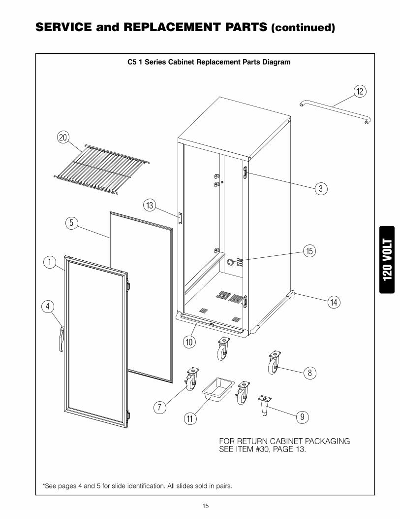
*Seepages4and5forslideidentification.allslidessoldinpairs.
seRVICe and RePlaCeMenT PaRTs (continued)
C51SeriesCabinetReplacementPartsDiagram
120
volt
FoRRetURncaBinetPackagingSeeiteM#30,Page�3.
10
11
3
15
14
8
97
20
12
5
13
4
1

�6
seRVICe and RePlaCeMenT PaRTs (continued)
*Seepages4and5forslideidentification.allslidessoldinpairs.
C53SeriesCabinetReplacementPartsDiagram
120
volt
FoRRetURncaBinetPackagingSeeiteM#30,Page�3.
23
NOTE:Replacement panels are ordered by color. See chart on page 13.
7 11
10
8
28
27
4
2
1OR
6
5OR
2524 OR
3
15
26
13

�7
seRVICe and RePlaCeMenT PaRTs (continued)C5-CM2000ORC5-CM1500COMBOMODULE
120
volt
FoRRePLaceMentc5-cM2000MoDULe,oRDeRiteM#5�onPage�4FoRRePLaceMentc5-cM�500MoDULe,oRDeRiteM#54onPage�4
49
41
47
3941
423733
45
3132
32
30
34
34
47
46
48
4040A
OR
38
44A44 OR
43A43 OR
36
BottoMcoVeR
aiRDUct
WateRPanencLoSURe
aiRDiScHaRgecoVeR
intakecoVeR
contRoLPaneL
MoDULecHaSSiS
MoiStURetHeRMoStatBULB
HeattHeRMoStatBULB&tHeRMoMeteRSenSoR
35

�8
seRVICe and RePlaCeMenT PaRTs (continued)C5-HM2000ORC5-HM1500HOLDINGMODULE
4040A
OR
120
volt
49
39 37
3345
48
BottoMcoVeR
47
46
44A44 OR 43A43 OR
aiRDiScHaRgecoVeR
4236
3230
34
38
WateRPanencLoSURe
aiRintakecoVeR
contRoLPaneL
MoDULecHaSSiS
aiRDUct
FoRRePLaceMentc5-HM2000MoDULe,oRDeRiteM#52onPage�4FoRRePLaceMentc5-HM�500MoDULe,oRDeRiteM#55onPage�4
HeattHeRMoStatBULB&tHeRMoMeteRSenSoR
35

�9
seRVICe and RePlaCeMenT PaRTs (continued)C5-PM1500PROOFINGMODULE
120
volt
49
41
47
3941
423733
45
3232
30
34
48
38
44A43A
BottoMcoVeR
aiRDUct
WateRPanencLoSURe
aiRDiScHaRgecoVeR
aiRintakecoVeR
contRoLPaneL
MoDULecHaSSiS
MoiStURetHeRMoStatBULB
36
FoRRePLaceMentc5-PM�500MoDULe,oRDeRiteM#53onPage�4
HeattHeRMoStatBULB&tHeRMoMeteRSenSoR
35

20
120
volt
seRVICe and RePlaCeMenT PaRTs (continued)C5-MM2000MOISTUREHOLDINGMODULE
FoRRePLaceMentc5-MM2000MoDULe,oRDeRiteM#56onPage�4
49
50
47
39
423733
45
3132
32
30
34
34
47
46
48
40
38
44
43
36
BottoMcoVeR
aiRDUct
WateRPanencLoSURe
aiRDiScHaRgecoVeR
intakecoVeR
contRoLPaneL
MoDULecHaSSiS
MoiStURetHeRMoStatBULB
HeattHeRMoStatBULB&tHeRMoMeteRSenSoR
35

2�
seRVICe and RePlaCeMenT PaRTs (continued)WIRINGDIAGRAMC5-CM2000ORC5-CM1500COMBOMODULE
19"BLK
19"WHT
27" WHT
10"BLK
16"BLK
25"BLK
10"BLK
25"BLK
34"BLK
1360 OR 1950 W ELEMENT
EE
19
19Z
Z
8
A
2
8
20
3
23
22MASTER POWERSWITCH
HEAT THERMOSTAT
AMBERLIGHT
THERMOMETER
TRANSFORMER
2410
17 13
23
22
21
20
7
10
2 3
4
17
1824
23
12
11
6
5
22
21
20
19
10
9
8
7
16
15
14
13
4
3
2
1
TERM BLOCK
Z
7WHITE
BLACK
GREEN
GRN GROUND SCREWPOWER CORD 20A FOR C5-CM2000 15A FOR C5-CM1500
STRAIN RELIEF
13
1
AIR DUCT
THERMAL CUT-OUT
THERMOMETER SENSOR
HEAT THERMOSTAT BULB
BLOWER MOTOR
1
30"BLK
30" BLK
25" WHT
30"BLK
8.50"BLK
10"BLK
16"BLK
25"BLK
19"BLK
10"BLK
16"BLK16" BLK
675 W ELEMENT
675 W ELEMENT
MOISTURETHERMOSTAT BULB
WATER PAN ENCLOSURE
MOISTURE THERMOSTAT
AMBERLIGHT
TOP OF MODULE
8
B
C
21
4B
8
CONTROL PANEL
19
8
8
24
XX
X X
SELCTOR SWITCH
E
DC
17
17E
BB
BA
120
volt

22
seRVICe and RePlaCeMenT PaRTs (continued)WIRINGDIAGRAMC5-HM2000ORC5-HM1500HOLDINGMODULE
STRAIN RELIEF
A
3
10
24
POWER CORD 20A FOR C5-HM2000 15A FOR C5-HM1500 GRN GROUND SCREW
GREEN BLACK
WHITE
BLOWER MOTORHEAT THERMOSTAT BULB
THERMOMETER SENSOR
THERMAL CUT-OUT
1360 OR 1950 WATT ELEMENT
AIR DUCT
TERMINAL BLOCK
TRANSFORMER THERMOMETER AMBER LIGHT
HEAT THERMOSTAT
MASTER POWERSWITCH
TOP OF CONTROL PANEL
1
2
3
4
13
14
15
16
7
8
9
10
19
20
21
22
5
6
11
12
23
2418
17
4
3
2
10
1
20
21
22
23
24
1917
1
Z
2
19
17
20
Z22
23
4
21
3
A
25"BLACK
8.50"BLACK10"
BLACK
10"BLACK
16"BLACK
30"BLACK
30"BLACK
30"BLACK
19"BLACK
25"BLACK
19"WHITE
25"WHITE
16"BLACK
25"BLACK
A
A
17
120
volt

23
seRVICe and RePlaCeMenT PaRTs (continued)WIRINGDIAGRAMC5-PM1500PROOFINGMODULE
T2
20
3
23
22
MASTER POWERSWITCH
HEAT THERMOSTAT
AMBERLIGHTTHERMOMETER TRANSFORMER
24
10
17 13
23
22
21
20
7
10
23
4
17
1824
23
12
11
6
5
22
21
20
19
10
9
8
7
16
15
14
13
4
3
2
1
TERMINAL BLOCK
Z
7WHITE
BLACKGREEN
GRN GROUND SCREW
POWER CORD
STRAIN RELIEF
13
1
AIR DUCT
THERMAL CUT-OUT
THERMOMETER SENSOR
HEAT THERMOSTAT BULB
BLOWER MOTOR
1
8
10"BLACK
30"BLACK
30"BLACK
27"BLACK
19"WHITE
25"WHITE
30"BLACK
8.50"BLACK
10"BLACK
16"BLACK
25"BLACK
19"BLACK
10"BLACK
16"BLACK
16"BLACK
16"BLACK
25"WHITE
17
A
2
A A
27"WHITE
9"BLACK
675 W ELEMENT
675 W ELEMENT
MOISTURE THERMOSTAT BULB
WATER PAN ENCLOSURE
MOISTURE THERMOSTAT
AMBERLIGHT
TOP OF MODULE
8
8
T2
21
4
T2
T2
CONTROL PANEL
19
Z
19
120
volt

24
seRVICe and RePlaCeMenT PaRTs (continued)WIRINGDIAGRAMC5-MM2000MOISTUREHOLDINGMODULE
21
T2
MOISTURETHERMOSTAT
CONTROL PANEL
4
TOP OF MODULE
AMBERLIGHT
MOISTURE THERMOSTAT BULB
120V 1360 W ELEMENT
10"BLACK
27"WHITE
17
25"WHITE
16"BLACK
16"BLACK 16"
BLACK10"BLACK
19"BLACK
25"BLACK
16"BLACK
10"BLACK
8.50"BLACK
30"BLACK
25"WHITE
27"BLACK
30"BLACK
30"BLACK
8
1
BLOWER MOTOR
HEAT THERMOSTAT BULB
THERMOMETER SENSOR
THERMAL CUT-OUT
AIR DUCT
1
13
STRAIN RELIEF
POWER CORD 125VAC 20A
GRN GROUND SCREW
GREEN BLACK
WHITE 7
Z
TERMINAL BLOCK
1
2
3
4
13
14
15
16
7
8
9
10
19
20
21
22
5
6
11
12
23
2418
17
4
3
2
10
7
20
21
22
23
1317
10
24
120V TO12V DC TRANSFORMER
THERMOMETER
AMBERLIGHT
HEAT THERMOSTAT
MASTER POWER SWITCH
22
23
3
20
10"BLACK
120V , 590W ELEMENT
WATER PAN ENCLOSURE
3
3
T2
T2
A
A
2
27"WHITE
27"BLACK
CC

25
InterMetro Industries Corporation (hereinafter referred to as “Seller”) warrants to the

CU
T A
lOn
g D
OT
TE
D l
InE
CUT AlOng DOTTED lInE
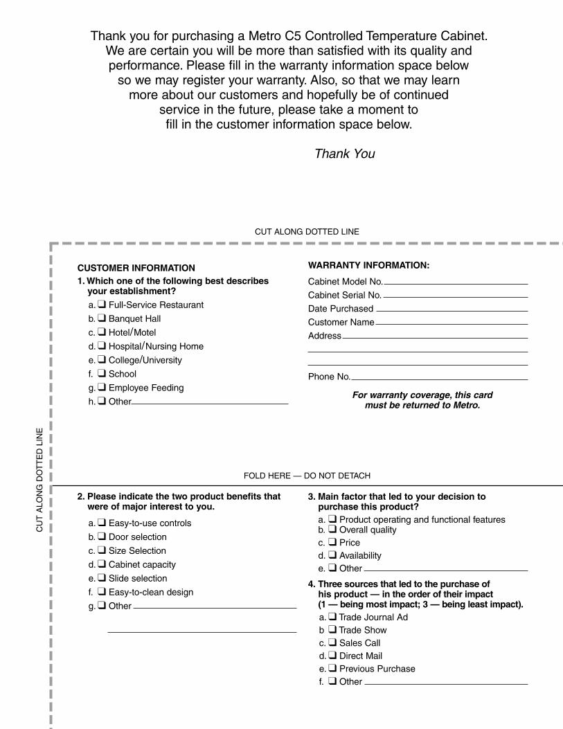
CUSTOMERINFORMATION1.Whichoneofthefollowingbestdescribes
yourestablishment?
a. ❑ Full-Service Restaurant
b.❑ Banquet Hall
c. ❑ Hotel/Motel
d. ❑ Hospital/nursing Home
e. ❑ College/University
f. ❑ School
g. ❑ Employee Feeding
h. ❑ Other
Thank you for purchasing a Metro C5 Controlled Temperature Cabinet. We are certain you will be more than satisfied with its quality and performance. Please fill in the warranty information space below
so we may register your warranty. Also, so that we may learn more about our customers and hopefully be of continued
service in the future, please take a moment tofill in the customer information space below.
Thank You
WARRANTYINFORMATION:
Cabinet Model no.
Cabinet Serial no.
Date Purchased
Customer name
Address
Phone no.
for warranty coverage, this card must be returned to metro.
2.Pleaseindicatethetwoproductbenefitsthatwereofmajorinteresttoyou.
a. ❑ Easy-to-use controls
b. ❑ Door selection
c. ❑ Size Selection
d. ❑ Cabinet capacity
e. ❑ Slide selection
f. ❑ Easy-to-clean design
g. ❑ Other
FOlD HERE — DO nOT DETACH
3.Mainfactorthatledtoyourdecisiontopurchasethisproduct?
a. ❑ Product operating and functional features b. ❑ Overall quality c. ❑ Price d. ❑ Availability e. ❑ Other
4.Threesourcesthatledtothepurchaseofhisproduct—intheorderoftheirimpact(1—beingmostimpact;3—beingleastimpact).a. ❑ Trade Journal Adb ❑ Trade Showc. ❑ Sales Calld. ❑ Direct Maile. ❑ Previous Purchasef. ❑ Other

FOlD HERE — DO nOT DETACH
STA
PlE
HE
RE
STA
PlE
HE
RE
PosTage Will Be Paid BY
INTERMETRO INDUSTRIES CORPORATIONATTn: CUSTOMER SERvICEP O BOx AWIlKES-BARRE PA 18705-9968
STAPlE HERE
nO POSTAgE nECESSARy
IF MAIlED In THE
UnITED STATES
BUSINESSREPLYMAIL FIRST-ClASTAInlESS STEEl PERMIT nO. 121 WIlKES-BARRE, PA


![VCM-CF Series Voice Module Operating Manual - hmt.com.t · 123 Parallel BCD [X0 - X7] X8 - X31-- ... VCM-CF Series Voice Module Operating Manual . VCM-CF Series Voice Module Operating](https://img.dokumen.tips/doc/110x75/5c4b532393f3c350ba7ba172/vcm-cf-series-voice-module-operating-manual-hmtcomt-123-parallel-bcd-x0.jpg)