Embed Size (px)
Citation preview

TM 11 -6625 -366 -10
TECHNICAL MANUAL
OPERATIONS MANUAL
FOR
MULTIMETER TS-352B/U
(NSN 6625-00-553-0142)

Be extremely careful when making high voltageand current measurements. Serious injury ordeath may result if safety precautions are notobserved.
DON’T TAKE CHANCES !
DANGEROUS VOLTAGES EXIST AT THE50V TO 5000V JACKS AND DC CURRENT
JACKS

TM 11-6625-366-10
TECHNICAL MANUAL HEADQUARTERS,DEPARTMENT OF THE ARMY
No. 11-6625-366-10 WASHINGTON, DC 12 November 1976
OPERATOR’S MANUALFOR
MULTIMETER TS-352B/U(NSN 6625-00-553-0142)
REPORTING OF ERRORSYou can help improve this manual by
calling attention to errors and by recom-mending improvements and stating yourreasons for the recommendations. Your let-ter or DA Form 2028 (RecommendedChanges to Publications and Blank Forms)should be mailed direct to Commander, USArmy Electronics Command, ATTN:DRSEL-MA-Q, Fort Monmouth, NJ 07703.
A reply will be furnished direct to you.
* This manual supersedes so much of TM 11-6625-366-15,5 January 1967, including all changes, as pertains to oporationand operator’s maintenance.
i
ParagraphCHAPTER 1. INTRODUCTION
Section I. GeneralScope . . . . . . . . . . . . . . . . . . . . . . 1-1Indexes of publications. . . . . . . . 1-2Forms and records . . . . . . . . . . . 1-3Administrative storage . . . . . . . 1-4Destruction of army electronics
materiel . . . . . . . . . . . . . . . . . . 1-5II. Description and data
Purpose and use . . . . . . . . . . . . . 1-6Description . . . . . . . . . . . . . . . . . 1-7Tabulated data . . . . . . . . . . . . . . 1-8Items comprising an operable
Multimeter TS-352B/U . . . . 1-9Additional equipment required 1-10
CHAPTER 2. OPERATING INSTRUCTIONSSection I. Controls, meter, and connectors
Damage from improper settings. 2-1Controls, meter, and connectors,
function . . . . . . . . . . . . . . . . . . 2-2II. Operating procedures
Preliminary operatingprocedures . . . . . . . . . . . . . . . 2-3
Voltage measurements. . . . . . 2-4Resistance measurements . . . . . 2-5Direct current measurements . . 2-6Procedures for testing transistor
circuits . . . . . . . . . . . . . . . . . . . 2-7Shutdown and storage
procedures . . . . . . . . . . . . . . . 2-8CHAPTER 3. MAINTENANCE
INSTRUCTIONSSection I. Preventive maintenance checks
and servicesPreventive maintenance. . . . . . . 3-1
Page
1-11-11-11-2
1-2
1-21-31-3
1-61-6
2-1
2-1
2-42-82-102-12
2-13
2-15
3-1
ii

ParagaphCHAPTER 3. Preventive maintenance checksSection I. and services periods . . . . . . . . 3-2Cont. Operator/crew daily preventive
maintenance checks andservices chart . . . . . . . . . . . . . 3-3
Operator/crew weeklypreventive maintenancechecks and services chart . . . . 3-4
Cleaning . . . . . . . . . . . . . . . . . . . 3-5II. Troubleshooting
General troubleshootinginformation . . . . . . . . . . . . . . . 3-6
Troubleshooting chart . . . . . . . . 3-7A PPENDIX A. REFERENCES . . . . . . . . . . . . .
B. BASIC ISSUE ITEMS LIST(BILL) AND ITEMSTROOP INSTALLED ORAUTHORIZED LIST(ITIAL) (Not applicable)
Page
3-2
3-3
3-43-5
3-63-7A-1
iii


CHAPTER 1INTRODUCTION
Section I. GENERAL
1-1. Scopea. General. This manual contains operating in-
structions for Multimeter TS-352B/U. Completeoperator maintenance instructions are also pro-vided.
b. Purpose. This manual is for use whenoperating and maintaining Multimeter TS-352B/U.
1-2. Indexes of Publicationsa. DA Pam 310-4. Refer to the latest issue of
DA Pam 310-4 to determine whether there arenew editions, changes, or additional publicationspertaining to the equipment.
b. DA Pam 310-7. Refer to DA Pam 310-7 todetermine whether there are modification workorders (MWOs) pertaining to the equipment.
1-3. Forms and Recordsa. Reports of Maintenance and Unsatisfactory
Equipment. Maintenance forms, records, andreports which are to be used by maintenance per-sonnel at all maintenance levels are listed in andprescribed by TM 38-750.
1-1
b. Report of Packaging and Handling Deficien -cies. Fill out and forward DD Form 6 (PackagingImprovement Report) as prescribed in AR 700-58/NAVSUPINST 4030.29/AFR 71-13/MCOP4030.29A, and DSAR 4145.8.
c. Discrepancy in Shipment Report (DISREP)(SF 361). Fill out and forward Discrepancy inShipment Report (DISREP) (SF 361) as pre-scribed in AR 55-38/NAVSUPINST 4610.33A/AFR 75-18/MCO P4610.19B and DSAR 4500.15.
1-4. Administrative Storage
Administrative storage of equipment issued toand used by Army activities shall be in accord-ance with TM 740-90-1.
1-5. Destruction of Army Electronics MaterielDestruction of Army electronics materiel to pre-vent enemy use shall be in accordance with TM750-244-2.
Section Il. DESCRIPTION AND DATA
1-6. Purpose and Use
The TS-352B/U is a portable, self-contained unitthat provides maintenance personnel with ameans of on-the-spot troubleshooting. The unitallows voltage, resistance, and current measure-ments. The versatility and limitations of the TS-352B/U are defined in paragraph 1-8.
1-2

1-7. Description
(fig. 1-1)The TS-352B/U is a volt-ohm-ampere meter thatuses self-contained batteries and is contained in ametal, immersionproof carrying case. The tech-nical characteristics of the TS-352B/U are pro-vided in paragraph 1-8, and paragraph 1-9 liststhe components that comprise the TS-352B/U.
1-8. Tabulated Data.Tabulated data for the test set are listed in table1-1.
T a b l e 1 - 1 . TS-35Bm Tab&ted Data
‘rypee. o . . . . . . . . . . . . . Multirange instrument ueing a
Wrnkronmpere dc, DArsonval-
type meter. Rectification is used
for ac voltage meaauremente.
Requency range . . . . . . . 25 Hertz to 5 kiloHertq useftd to
20 kiloHertz with a reduction in
.9ensitivit y.
frequency error. . . . . . . . *3 percent at 10 kiloHertG *7
percent at 20 kiloHertz.
Usable tempratwe range -40”F to +181’’F’.
Meter =neitivity . . . . . . . 1!300 ohms per volt far ac ranges;
1,000 or 20,000 ohms per volt for
de ranges.
Aee~acy*
Ik2 range:
O to 1,000 volts and dc *6 percent at -40”F; Sf percent at
current (1,000 ‘77T; *5 percent at 131T.
ohms per volt )
* Percentages are of full scale readings.
1-3

Figure 1-1.
1-4
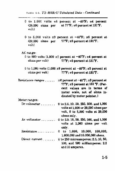
T a b l e 1-1 . TS-352Bm Tabdated Data - Continued
O to 1.000 volts *8 percent at -4(FF; *4 percent
(20,m Oh~S P at WI’; *6 percent at 13117.
volt]
O to 5,000 volts *9 percent at -40’T; M percent at
(20,W ohms per WF’; *8 percent at 131T.
volt )
A(2 range:
O to m volts (I,m *7 percent at -40T; *4 percent at
ohms per volt) 77W; *5 percent at 131T.
O to I,m volts (I,MO &$ percent at -4(VT; *5 percent at
ohms per volt) TTT; *6 percent at 131T.
Wsistanee rages . . . . . . *6 percent at -MT; S3 percent at
TPF; *5 percent at 131 T’. (Per-
cent values are in terms of
meter scale, not of ohtqs in-
dicated by meter pointer.)
Meter ranges:
Wvoltmeter . . . . . . . . 0 to 2.5, 10,50,250,500, and 1,000
volts at 1,000 or 20,000 ohms per
volt, O to 5,000 volts at 20,000
ohms only.
/% voltmeter . . . . . . . . 0 to 2.5, 10, 50, 250, 500, and 1,000
volts at 1,000 Qhms per volt
only.
Resistance . . . . . . . . . . o to 1,000, 10,000, 100,000,
I,W,WO and 10,000,000 ohms.
Direct ewrent . . . . . . . 0 to 250 mkrorunperes; 2.& 10, 50,
100, and 000 milliamperes; 2.5
and 10 amperes.
1-5

Table 1 -1 . TS-i?52B/U Tabulated Data – Continued
Power supply . . . . . . . . . . Supplied by batteries for
ohmmeter operation (1.5 and
13.5 volts).
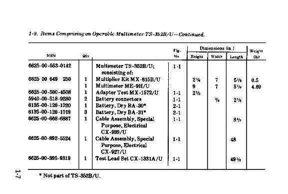
1-9. Items Comprising an Operable MultimeterTS-352B/U
The items comprising an operable TS-352B/U arelisted on the following page.
1-10. Additional Equipment Required
Three Dry Batteries BA-31 and one Dry BatteryBA-30 are required, but not furnished. To supplypower to Multimeter TS-352B/U, the operator isrequired to install the batteries in the batterycompartment. For battery installation instruc-tions, refer to paragraph 2-3.
1-6
1-9.
1-7


CHAPTER 2OPERATING INSTRUCTIONS
Section I. CONTROLS, METER,AND CONNECTORS
2-1. Damage From Improper Settings
Haphazard operation or improper setting of thecontrols can damage the TS-352B/U; therefore,knowledge of the functions of the meter, controls,and connectors before operating the TS-352B/Uis important. Refer to paragraph 2-2.
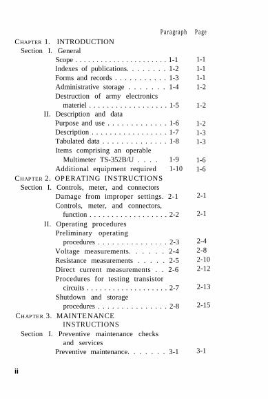
2-2. Controls, Meter, and connectors, Functions
(fig. 2-1)The following chart lists the controls, meter, andconnectors of the TS-352B/U and indicates theirfunctions.
Item Function
FUNCTION switch Used to select type of operation
desired.
Range switch Used to select appropriate dc or
resistance ranges.
OHMS ZERO ADJ knob Used to adjust meter pointer to
zero on ohms sale.
Meter Indicates value of voltage, resist-
ance, or current being
measured.
2-1
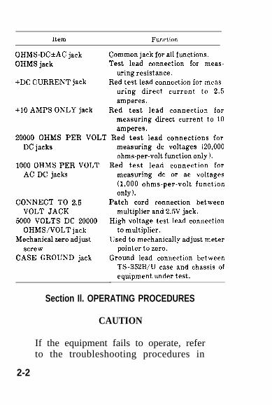
Item Function
OHMS-DC*AC jack Common jack for all functions.
OHMS jack Test lead connection for meas-
uring resistance.
+DC CURRENT jack Red test lead connection for meas-
uring direct current to 2.5
amperes.
+10 AMPS ONLY jack Red test lead connection for
measuring direct current to 10
amperes.
20000 OHMS PER VOLT Red test lead connections for
DC jacks
1000 OHMS PER VOLT
AC DC jacks
CONNECT TO 2.5
VOLT JACK
5000 VOLTS DC 20000
OHMS/VOLT jack
Mechanical zero adjust
screw
CASE GROUND jack
measuring dc voltages (20,000
ohms-per-volt function only ).
Red test lead connection for
measuring dc or ac voltages
(1,000 ohms-per-volt function
only).
Patch cord connection between
multiplier and 2.5V jack.
High voltage test lead connection
to multiplier.
Used to mechanically adjust meter
pointer to zero.
Ground lead connection between
TS-352B/U case and chassis of
equipment under test.
Section Il. OPERATING PROCEDURES
CAUTION
If the equipment fails to operate, referto the troubleshooting procedures in
2-2

Figure 2-1. Panel control and jacks.2-3

paragraph 3-6 and 3-7. Haphazard trou-bleshooting can damage the TS-352B/U.
2-3. Preliminary Operating Proceduresa. Battery Installation. To install the batteries
in the multimeter (fig. 2-2), place the multimeterface down on a flat firm surface and proceed asfollows:
(1) Loosen the retaining screws that holdthe cover in place by turning the screws counter-clockwise.
(2) Lift up and remove the cover. Place thecover so that the connection diagram on the in-side of the cover (fig. 2-3) can be easily referredto in order to make the necessary connections.
(3) Connect three Dry Batteries BA-31 inseries; use the connectors supplied. Install thebatteries in the battery compartment, as indi-cated by the connection diagram on the batterycompartment cover.
(4) Place Dry Battery BA-30 in the compart-ment provided so the spring makes contact withthe bottom of the battery.
(5) Place the battery compartment cover onthe bottom of the multimeter.
(6) Align the retaining screws with theirproper holes.
(7) Hold the cover to prevent it from shift-ing, and secure the cover in position by turning
2-4

Figure 2-2.
2-5

2-6Figure 2-3. Battery connection diagram on
inside compartment cover.

the retaining screws clockwise with a suitablescrewdriver until tight.
b. Preliminary Starting Procedure. Before us-ing the TS-352B/U, carefully read the operatinginstructions (para 2-4 through 2-7). For maxi-mum accuracy in all measurements, use the rangethat will produce a meter indication as close tomidscale as possible.
CAUTION
When measuring unknown voltage orcurrent values, start at the highestrange and reduce the range a step at atime until midscale deflection is ob-tained on the meter. Excessive voltageor current values that cause greaterthat full scale deflection can damage themeter.
NOTE
Before using the TS-352B/U, check themechanical zero of the meter. If themeter pointer is not exactly over thezero line, reset by using the proper sizescrewdriver to adjust the small screwset into the glass of the meter face.
Refer to figure 2-1 for location of all con-trols and indicators.
2-7
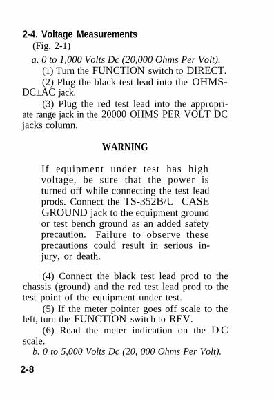
2-4. Voltage Measurements(Fig. 2-1)
a. 0 to 1,000 Volts Dc (20,000 Ohms Per Volt).(1) Turn the FUNCTION switch to DIRECT.(2) Plug the black test lead into the OHMS-
DC±AC jack.(3) Plug the red test lead into the appropri-
ate range jack in the 20000 OHMS PER VOLT DCjacks column.
WARNING
If equipment under test has highvoltage, be sure that the power isturned off while connecting the test leadprods. Connect the TS-352B/U CASEGROUND jack to the equipment groundor test bench ground as an added safetyprecaution. Failure to observe theseprecautions could result in serious in-jury, or death.
(4) Connect the black test lead prod to thechassis (ground) and the red test lead prod to thetest point of the equipment under test.
(5) If the meter pointer goes off scale to theleft, turn the FUNCTION switch to REV.
(6) Read the meter indication on the D Cscale.
b. 0 to 5,000 Volts Dc (20, 000 Ohms Per Volt).
2-8

(1) Insert Cable Assembly, Special Purpose,Electrical CX-927/U (fig. 1-1) in the 5000 VOLTSDC 20000 OHMS/VOLT jack of Multiplier KitMX-815B/U.
(2) Connect Cable Assembly, Special Pur-pose, Electrical CX-939/U (fig. 1-1) between themultiplier and the 20000 OHMS PER VOLT DC2.5V jack of the TS-352B/U.
(3) Turn the FUNCTION switch to DIRECT.(4) Plug the black test lead into the OHMS-
DC±AC jack.(5) Connect the black test lead prod to the
chassis ground, and the clamp of Cable Assembly,Special Propose, Electrical CX-927/U to the testpoint of the equipment under test, and turn onthe equipment.
(6) If the meter pointer goes off scale to theleft, turn the FUNCTION switch to REV.
(7) Read the meter indication on the 0 to 5DC scale.
c. 0 to 1,000 volts DC (1,000 Ohms Per volt.)(1) Turn the FUNCTION switch to
1000 Ω /VDC.(2) Plug the black test lead into the OHMS-
DC±AC jack.(3) Plug the red test lead into the appropri-
ate 1000 OHMS PER VOLT AC DC jack.(4) Connect the black test lead prod to the
chassis (ground), and the red test lead prod to thetest point of the equipment under test.
2-9

(5) If the meter goes off scale to the left,reverse the test lead prods.
(6) Read the meter indication on the DCscale.
d. 0 to 1,000 Volts Ac.(1) Turn the FUNCTION switch to A C
VOLTS.(2) Plug the black test lead into the OHMS-
DC±AC jack.(3) Plug the red test lead into the appropri-
ate 1000 OHMS PER VOLT AC DC jack.(4) Connect the black test lead prod and the
red test lead prod to the points in the circuit be-tween which the voltage is to be measured.
(5) Read the meter indication on the A Cscale.
2-5. Resistance Measurementsa. Multimeter Zero Adjusting. Zero adjust the
multimeter before making resistance measure-ments. Each time the range switch is turned to adifferent resistance range, repeat the zero ad-justing procedures as follows:
(1) Turn the FUNCTION switch to OHMS.NOTE
Do not leave the FUNCTION switch inthe OHMS position any longer than nec-essary to perform the resistance tests.Leaving the switch in this position willdrain the batteries.
2-10

(2) Plug the black test lead into the OHMS-DC±AC jack.
(3) Plug the red test lead into the OHMSjack.
(4) Set the range switch to the desired posi-tion and touch the two test lead prods together.
(5) Turn the OHMS ZERO ADJ. knob untilmeter pointer appears directly over the 0 on theright side of the OHMS scale.
(6) Separate the test lead prods.b. Measuring Resistance.
(1) Repeat procedures described in a (l), (2),and (3) above.
(2) If the approximate resistance of the cir-cuit under test is known, turn the range switch tothe appropriate resistance range and zero adjustthe meter (a (4), (5), and (6) above).
(3) Connect the test prods across the resist-ance to be measured.
(4) Read the meter indication on the OHMSscale.
(5) If the resistance to be measured is un-known, proceed as follows:
(a) Set the range switch to RX10000.(b) Connect the test prods across the un-
known resistance.(c) Turn the range switch counterclock-
wise, one range at a time, until the meter pointerstops close to midscale.
(6) Zero adjust the meter (a (4), (5), and (6)
2-11

2-6. Direct Current Measurement(fig. 1-1)
CAUTION
When measuring current, always con-nect the multimeter in series with thecircuit under test. Be sure that the leadpolarity is observed (black-negative andred-positive). Wrong connections maydamage the multimeter. Do not measuremore than 10 amperes.
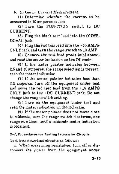
a. Known Curret Measurement.(1) Turn the FUNCTION switch to D C
CURRENT.(2) Plug the black test lead into the OHMS-
DC±AC jack.(3) If the current is known to be more than
2.5 amperes, but less than 10 amperes, plug thered test lead into the +10 AMPS ONLY jack andturn the range switch to the appropriate range.
(4) Connect the test lead prods to the pointsin the circuit in which the current is to bemeasured.
(5) Read the meter indication on the D Cscale.
2-12
2-13
2-7.

test. Damage will result from any external volt-ages which are applied to the ohms circuit of theTS-352B/U.
b. If the equipment contains transistors, anddoes not have an isolation transformer in itspower supply circuit, connect one in the power in-put circuit. A suitable transformer is identifiedby National stock No. 5950-00-256-1779.
c. Make connections carefully so that shortswill not be caused by exposed test prod or clipconnections. Tape or sleeve (spaghetti) test prodsor clips to leave a little exposed as needed tomake contact to the circuit under test.
d. When the TS-352B/U is used for resistancemeasurements on transistorized equipment, usethe RX100 range only. The negative lead of theohmmeter circuit is connected to the positive sideof the battery. The equipment battery (or itsequivalent) is recommended as the source ofpower when servicing transistorized equipment.Observe battery polarity. Polarity reversal maydamage the transistors or electrolytic capacitorsin the circuit. If a battery eliminator is used inplace of the battery, it must have good voltageregulation and low ac ripple. Good regulation isimportant because the output voltage of a batteryeliminator with poor regulation may exceed themaximum voltage rating of the transistors in theequipment being tested. A battery eliminatorwith poor ac filtering will create a false indication
2-14
of poor filtering in the equipment being tested.e. Turn off the transistorized equipment
before switching the battery eliminator on or off.The transient voltages, created by switching thebattery eliminator on and off, may exceed thepunch-through rating of the transistors. Makesure that a normal load (such as a speaker for areceiver) is connected to the transistorized equip-ment before applying power.
f. Refer to the individual technical manual forthe equipment being tested.
2-8. Shutdown and Storage Proceduresa. Shutdown Procedure.
(1) Remove all test leads and accessoriesfrom the jacks of the TS-352B/U and place themin the test leads and accessories compartment(fig. 1-1).
(2) Place the FUNCTION switch in the ACVOLTS position.
b. Storage.(1) The original packing material may be
used for repacking.
CAUTION
Do not leave batteries in battery com-partment for an extended period oftime. Corrosion of the batteries couldlead to severe damage to the equipment.
2-15
(2) Pack the TS-352B/U securely to preventdamage during transit or limited storage. Usesufficient wadding. Protect the equipment fromrain or snow.
2-16
CHAPTER 3
MAINTENANCE INSTRUCTIONS
Section I. PREVENTIVE MAINTENANCE CHECKSAND SERVICES
3-1. Preventive Maintenance
Operator’s preventive maintenance is the sys-tematic care, servicing, and inspection of equip-ment to prevent the occurrence of trouble, to re-duce downtime, and to assure that the equipmentis serviceable.
a. Systematic Care. The procedures given inparagraphs 3-3, 3-4, and 3-5 cover routinesystematic care and cleaning essential to properupkeep and operation of the equipment. Itemnumbers indicate the sequence of minimum in-spection requirements.
b. Preventive Maintenance Checks and Serv-ices. The preventive maintenance checks andservices charts (para 3-3 and 3-4) outline func-tions to be performed at specific intervals. Thesechecks and services are designed to maintainArmy equipment in a combat-serviceable condi-tion; that is, in good general (physial) conditionand in good operating condition. The charts in-dicate what to check, how to check, and the nor-mal conditions. References included are to para-graphs that contain detailed repair or replace-
3-1

ment procedures. Defects discovered duringoperation of the test set will be noted for futurecorrection, to be made as soon as operation hasceased. Operation will be stopped immediately ifa deficiency is noted which would damage theequipment. If the defect cannot be remedied bythe operator, higher category of maintenance orrepair is required. Records and reports of thesechecks and services must be made in accordancewith TM 38-750.
3-2. Preventive Maintenance Checks and ServicesPeriods
Preventive maintenance checks and services ofthe TS-352B/U are required daily (only if theequipment is to be used that day) and weekly.
a. Paragraph 3-3 specifies the checks and serv-ices that must be performed every day that theequipment is used, and under the special condi-tions listed below:
(1) Before the TS-352B/U is taken on a mis-sion.
(2) When the TS-352B/U is initially in-stalled.
(3) When the TS-352B/U is reinstalled afterremoval for any reason.
(4) At least once a week, if the equipment ismaintained in standby condition.
b. Paragraph 3-4 specifies additional checks
3-2

and services that must be performed on a weeklybasis.
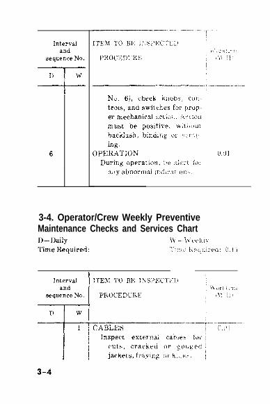
3-3. Operator/Crew Daily PreventiveMaintenance Checks and Services Chart
D–Daily w –weekly
Time Requred: 0.16 hf/H Time Required:
Intervaland
sequence No.
D
1
2
3
4
5
w
ITEM TO BE INSPECTED
PROCEDURE
TS-%BIW
Check equipment for com-
pleteness and general condi-
tion (para 1 -8) .
EXTERIOR SURFACES
Clean exterior surfaces of the
equipment ( p a r a 3 - 5 ) .
EXTERNAL JACKS
Inspect external jacks for
breakage and for firm
seating.
METER GLASS
Inspect front panel glaas win-
dow for damaged housing,
broken glaas, physical dam-
age, dust, or moisture.
KNOBS, CONTROLS, AND
SWITCHES
During operation (sequence
Worktime(M/H)
0.01
0.10
0.01
0.01
0.02
3-3
3-4
Intervaland
sequence No.
=!=
—
D w
6 (,(11
3-4. Operator/Crew Weekly PreventiveMaintenance Checks and Services Chart

w
2
3
4
ITEM To m INSPECTED
PROCEDURE
HARDWARE
Ins~et d exterior hmdwue
for Iweness, ad damage.
me Ts-*m/u cover’, car-
rying handle, hinges, and all
kits md aaews must be
tight ad not dmaged.
METAL SURFACES
Inspect exposed metal sl.lr-
faees for rust and and corro-
sion. If these conditions ex
M., refer to a higher main-
tenmce category for repair.
BATTERIES
Insped batteries for leakage,
mrrosion, and swelhng. lle-
place batteries if any of
these renditions exist ( p a r a
2 - 3 a ) .
k?orktimeM/H)
0.02
0.01
0.10
3-5. Cleaning.
Inspect the exterior of the TS-352B/U. The sur-faces should be clean, and free of dust, dirt,grease, and fungus.
a. Remove dust and loose dirt with a soft, cleancloth.
3-5
WARNINGThe fumes of trichloroethane are toxic.Provide thorough ventilation wheneverused. DO NOT USE NEAR ANOPEN FLAME. Trichloroethane is notflammable but exposure of the fumes toan open flame or hot metal surfaceforms highly toxic phosgene gas.
b. Remove grease, fungus, and ground-in dirtfrom the case with a cloth dampened (not wet)with trichloroethane.
c. Remove dust or dirt from plugs and jackswith a soft brush.
CAUTIONDo not press on the METER FACEwhen cleaning. Damage to the equip-ment may result.
d. Clean the front panel, meter face, and con-trols; use a soft, clean cloth. If necessary, dampenthe cloth with water or mild detergent for moreeffective cleaning.
Section Il. TROUBLESHOOTING
3-6. General Troubleshooting Information
a. Troubleshooting this equipment is based onthe operational check (para 2-1 through 2-5). Totroubleshoot the equipment, perform all func-
3-6

tions of the TS-352B/U operation (para 2-1through 2-5), and proceed with the functions untilan abnormal condition or result is observed. Notethe abnormal condition, or result, and refer to thetroubleshooting chart (para 3-7). Perform thechecks and corrective actions indicated in thetroubleshooting chart. If the corrective measuresindicated do not result in correction of the trou-ble, higher maintenance category repair is re-quired. Paragraphs 2-2, 2-3, and 2-4 contain addi-tional information and step-by-step instructionsfor performing equipment tests and adjustmentsto be used dining the troubleshooting proce-dures.
b. All possible malfunctions that may occur arenot listed, nor all tests or inspections and correc-tive actions. If a malfunction is not listed (exceptwhen malfunction and cause are obvious ) or is notcorrected by listed corrective actions, notify yoursupervisor.
3-7. Troubleshooting Chart.NOTE
Before using this chart, be sure all ap-plicable operating checks have been per-formed.
3-7

3-8

3-9


APPENDIX A
REFERENCES
Following is a list of applicable publicationsavailable to the operator of Mult imeterTS-352B/U:DA Pam 310-4 Index of Technical Manuals,
Technical Bulletins, Sup-ply Manuals (Types 7, 8,and 9), Supply Bulletins,and Lubrication Orders.
DA Pam 310-7 US Army Index of Modifica-tion Work Orders.
SB 11-6 Dry Battery Supply Data.TM 38-750 The Army Maintenance
M a n a g e m e n t S y s t e m(TAMMS).
TM 740-90-1 Administrative Storage ofEquipment.
TM 750-244-2 Procedures for Destructionof Electronics Materiel toP r e v e n t E n e m y U s e(Electronics Command).
By Order of the Secretary of the Army:
BERNARD W. ROGERSGeneral, United States Army
Official: Chief of Staff
PAUL T. SMITHMajor General, United States Army
The Adjutant General
DISTRIBUTION:
Active Amy:
USASA (2)
COE (1)
TSG (1)
USAARENBD (1)
DARCOM (1)
TRADOC (2)
OS Maj Cored (4)
LOGCOMDS (3)
MICOM (2)
TECOM (2)
USACC (4)
USACC-CONUS (2)
USACC-A (2)
USACC-EUR (2)
USACC-PAC (2)
USACC-SO (2)
MDW (1)
Armies (2)
Corps (2)
HISA (Ft Monmouth) (33)
SW Colleges (1)
USASESS (5)
USAADS (2)
USAFAS (2)
USAARMS (2)
USAIS [2)
WJLws c’?)
USAICS (3)
MAAG (1)
USARMIS (1)
USAJFKCENMA [2)
VFGH 62)
Instl (21 except
Fort GW311 (10)
Fort Gordon (Ill)
Fort Huaehuca (10)
Fort Cmmn (5)
Ft Richmdwn (ECOM) (2)
LBAD [14)
SAAD (30)
TOAD (14)
SHAD (3)
E@ FLDMS (1)
USAERDAA (1)
USAERDAW (1)
M (2)
Brig (2)
R@ M
Em (2)
JVG: State AG [3); Units–Same as Active Army except
dlowmce is one copy per unit.
USAR: N-One
l% explanation of abbreviations used, see AR 310-50.
U.S. IX3VERNIEW PR1fWING OFFICE , 1993 0 - 342-421 (630SS)


TM 11-6625-366-10
PIN : 012173-000

This fine document...
Was brought to you by me:
Liberated Manuals -- free army and government manuals
Why do I do it? I am tired of sleazy CD-ROM sellers, who take publicly available information, slap “watermarks” and other junk on it, and sell it. Those masters of search engine manipulation make sure that their sites that sell free information, come up first in search engines. They did not create it... They did not even scan it... Why should they get your money? Why are not letting you give those free manuals to your friends?
I am setting this document FREE. This document was made by the US Government and is NOT protected by Copyright. Feel free to share, republish, sell and so on.
I am not asking you for donations, fees or handouts. If you can, please provide a link to liberatedmanuals.com, so that free manuals come up first in search engines:
<A HREF=http://www.liberatedmanuals.com/>Free Military and Government Manuals</A>
– SincerelyIgor Chudovhttp://igor.chudov.com/
– Chicago Machinery Movers