Embed Size (px)
Citation preview
TM 11-6625-2866-14&P
TECHNICAL MANUAL
OPERATOR'S, ORGANIZATIONAL, DIRECT SUPPORT,AND GENERAL SUPPORTMAINTENANCE MANUAL
(INCLUDING REPAIR PARTS AND SPECIAL TOOLS LISTS)FOR
GENERATOR, TRACKING SG-1125/U(HEWLETT-PACKARD MODEL 8444A)
(NSN 6625-00-185-4802)
HEADQUARTERS, DEPARTMENT OF THE ARMY
29 FEBRUARY 1980
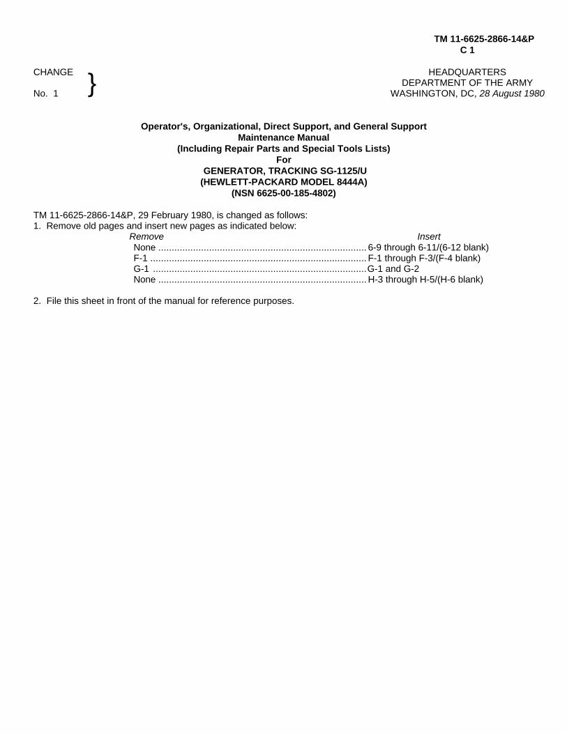
TM 11-6625-2866-14&PC 1
CHANGE HEADQUARTERSDEPARTMENT OF THE ARMY
No. 1 WASHINGTON, DC, 28 August 1980
Operator's, Organizational, Direct Support, and General SupportMaintenance Manual
(Including Repair Parts and Special Tools Lists)For
GENERATOR, TRACKING SG-1125/U(HEWLETT-PACKARD MODEL 8444A)
(NSN 6625-00-185-4802)
TM 11-6625-2866-14&P, 29 February 1980, is changed as follows:1. Remove old pages and insert new pages as indicated below:
Remove InsertNone .............................................................................. 6-9 through 6-11/(6-12 blank)F-1 ................................................................................. F-1 through F-3/(F-4 blank)G-1 ................................................................................G-1 and G-2None .............................................................................. H-3 through H-5/(H-6 blank)
2. File this sheet in front of the manual for reference purposes.
}
By Order of the Secretary of the Army:
E. C. MEYERGeneral, United States Army
Official: Chief of Staff
J. C. PENNINGTONMajor General, United States Army
The Adjutant General
Distribution:Active Army:
HISA (Ft Monmouth) (21) USAICS (3)USAINSCOM (2) MAAG (1)COE (1) USARMIS (1)TSG (1) USAERDAA (1)USAARENBD (1) USAERDAW (1)DARCOM (1) Fort Gordon (10)TRADOC (2) Fort Carson (5)OS Maj Comd (4) Army Dep (1) exceptTECOM (2) LBAD (14)USACC (4) SAAD (30)MDW (1) TOAD (14)Armies (2) SHAD (3)Corps (2) Fort Gillem (10)Svc Colleges (1) USA Dep (1)USASIGS (5) Sig Sec USA Dep (1)USAADS (2) Fort Richardson (CERCOM Ofc) (2)USAFAS (2) Units org under fol TOE:USAARMS (2) (2 copies each unit)USAIS (2) 29-207USAES (2) 29-610
ARNG: NoneUSAR: NoneFor explanation of abbreviations used, see AR 310-50.
This manual contains copyright material reproduced by permission of the Hewlett-Packard Company.
TM 11-6625-2866-14&P
TECHNICAL MANUAL HEADQUARTERSDEPARTMENT OF THE ARMY
No. 11-6625-2866-14&P WASHINGTON, DC, 29 February 1980
OPERATOR'S, ORGANIZATIONAL, DIRECTSUPPORT, AND GENERAL SUPPORT
MAINTENANCE MANUAL(INCLUDING REPAIR PARTS AND SPECIAL TOOLS LISTS)
FORGENERATOR, TRACKING SG-1 125/U(HEWLETT-PACKARD MODEL 8444A)
(NSN 6625-00-185-4802)
REPORTING ERRORS AND RECOMMENDING IMPROVEMENTSYou can improve this manual by recommending improvements using DA Form 2028-2 (Test) located in
theback of the manual. Simply tear out the self-addressed form, fill it out as shown on the sample, fold it whereshown, and drop it in the mail. If there are no blank DA Forms 2028-2 (Test) in the back of your manual, usethe standard DA Form 2028 (Recommended Changes to Publications and Blank Forms) and forward to theCommander, US Army Communications and Electronics Materiel Readiness Command, ATTN: DRSEL-ME-MQ, Fort Monmouth, NJ 07703.
In either case a reply will be furnished direct to you.
This manual is an authentication of the manufacturer's commercial literature which, through usage, has been found tocover the data required to operate and maintain this equipment. Since the manual was not prepared in accordance withmilitary specifications, the format has not been structured to consider levels of maintenance.
}
i

TM 11-6625-2866-14&P
TABLE OF CONTENTS
Section Page0. INTRODUCTION ..................................... 0-1I. GENERAL INFORMATION........................ 1-1
1-1. Introduction ...................................... 1-11-5. Safety Considerations ...................... 1-11-16. Instruments Covered by Manual ....... 1-21-18. Description ...................................... 1-21-21. 8554B RF Section Modifications....... 1-41-23. Accessories Supplied ....................... 1-41-25. Operating Accessories...................... 1-41-27. Warranty .......................................... 1-41-29. Recommended Test Equipment ....... 1-4
II. INSTALLATION......................................... 2-12-1. Initial Inspection ............................... 2-12-2. Mechanical Check ............................ 2-12-4. Electrical Check . ............................. 2-12-6. Claims for Damage. . ...................... 2-12-9. Preparation for Use. ....................... 2-12-10. Power Requirements ........................ 2-12-13. Power Cable..................................... 2-12-16. Operating Environment .................... 2-12-18. Installation Connections.................... 2-22-21. Storage and Shipment...................... 2-22-22. Original Packaging .......................... 2-22-26. Other Packaging Materials ............... 2-2
III. OPERATION ........................................... 3-13-1. Introduction ...................................... 3-13-3. Panel Features................................. 3-13-5. Operator's Checks............................ 3-13-7. Operating Instructions ...................... 3-13-9. Controls, Indicators and Connectors . 3-13-11. Operating Techniques...................... 3-13-13. Crystal Filter Measurement............... 3-83-15. Bandpass Filter Measurement .......... 3-83-17. Low-Pass Filter Measurement .......... 3-83-19. Swept Return Loss Measurement ..... 3-93-21. Amplifier Gain and Bandwidth
Measurement ............................. 3-93-23.Precision Frequency Measurements . 3-9
IV. PERFORMANCE TESTS .......................... 4-14-1. introduction ..................................... 4-14-3. Equipment Required......................... 4-14-5. Front Panel Checks.......................... 4-14-7. Preset Adjustments (8554B/8552B
Section Page 141T/84, 44A System ............................
4-9. Preset Adjustments (8555A/8552B/141T/8444A System)........................ 4-2
4-11. Performance Tests ........................... 4-24-16. Output Level..................................... 4-34-17. Frequency Stability .......................... 4-54-18. System Flatness .............................. 4-94-19. -Frequency Accuracy...................... 4-114-20. Harmonic Distortion........................ 4-13
V. ADJUSTMENTS .5 .................................... 5-15-1. Introduction ...................................... 5-15-4. Equipment Required......................... 5-15-6. Factory Selected Components.......... 5-15-8. Power Supply, Check and Adjustment 5-15-9. 1.55 GHz Oscillator Power Level,
Frequency Check & Adjustment. ...... 5-45-10. 1.55 GHz Oscillator Residual
FM Check . ..................................... 5-65-11. First Converter Check and
Adjustment ...................................... 5-95-12. Automatic Level Control (ALC)
Check and Adjustment .................. 5-115-13. Level Control Calibration Check
and Adjustment ............................. 5-13
VI. REPLACEABLE PARTS ............................ 6-16-1. Introduction ...................................... 6-16-3. Abbreviations. .................................. 6-16-5. Replaceable Parts List...................... 6-16-7. Ordering Information ........................ 6-1
VII. MANUAL CHANGES ................................. 7-17-1. Introduction ...................................... 7-17-5. Manual Change Instructions ............ 7-1
VIII. SERVICE .................................................. 8-18-1. Introduction ...................................... 8-18-3. Principles of Operation .................... 8-18-5. Recommended Test Equipment . ..... 8-18-7. Troubleshooting................................ 8-18-11. Repair ............................................ 8-18-20. General Service Hints ...................... 8-28-23. General Service Information............. 8-48-28. Operational Amplifiers. ..................... 8-58-31. Electrical Maintenance ..................... 8-6
ii
TM 11-6625-2866-14&P
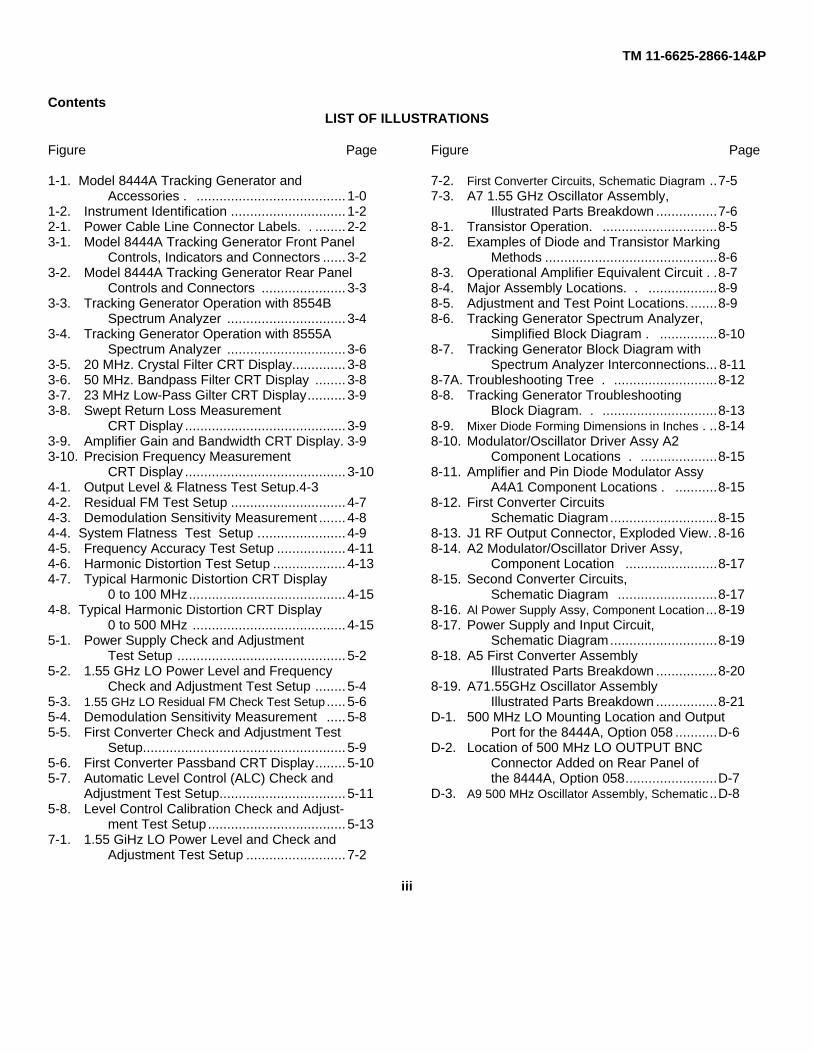
ContentsLIST OF ILLUSTRATIONS
Figure Page
1-1. Model 8444A Tracking Generator andAccessories . ....................................... 1-0
1-2. Instrument Identification .............................. 1-22-1. Power Cable Line Connector Labels. . ........ 2-23-1. Model 8444A Tracking Generator Front Panel
Controls, Indicators and Connectors ...... 3-23-2. Model 8444A Tracking Generator Rear Panel
Controls and Connectors ...................... 3-33-3. Tracking Generator Operation with 8554B
Spectrum Analyzer ............................... 3-43-4. Tracking Generator Operation with 8555A
Spectrum Analyzer ............................... 3-63-5. 20 MHz. Crystal Filter CRT Display.............. 3-83-6. 50 MHz. Bandpass Filter CRT Display ........ 3-83-7. 23 MHz Low-Pass Gilter CRT Display.......... 3-93-8. Swept Return Loss Measurement
CRT Display .......................................... 3-93-9. Amplifier Gain and Bandwidth CRT Display. 3-93-10. Precision Frequency Measurement
CRT Display .......................................... 3-104-1. Output Level & Flatness Test Setup.4-34-2. Residual FM Test Setup .............................. 4-74-3. Demodulation Sensitivity Measurement ....... 4-84-4. System Flatness Test Setup ....................... 4-94-5. Frequency Accuracy Test Setup .................. 4-114-6. Harmonic Distortion Test Setup ................... 4-134-7. Typical Harmonic Distortion CRT Display
0 to 100 MHz......................................... 4-154-8. Typical Harmonic Distortion CRT Display
0 to 500 MHz ........................................ 4-155-1. Power Supply Check and Adjustment
Test Setup ............................................ 5-25-2. 1.55 GHz LO Power Level and Frequency
Check and Adjustment Test Setup ........ 5-45-3. 1.55 GHz LO Residual FM Check Test Setup ..... 5-65-4. Demodulation Sensitivity Measurement ..... 5-85-5. First Converter Check and Adjustment Test
Setup..................................................... 5-95-6. First Converter Passband CRT Display........ 5-105-7. Automatic Level Control (ALC) Check and
Adjustment Test Setup................................. 5-115-8. Level Control Calibration Check and Adjust-
ment Test Setup.................................... 5-137-1. 1.55 GiHz LO Power Level and Check and
Adjustment Test Setup .......................... 7-2
Figure Page
7-2. First Converter Circuits, Schematic Diagram ..7-57-3. A7 1.55 GHz Oscillator Assembly,
Illustrated Parts Breakdown ................7-68-1. Transistor Operation. ..............................8-58-2. Examples of Diode and Transistor Marking
Methods .............................................8-68-3. Operational Amplifier Equivalent Circuit . .8-78-4. Major Assembly Locations. . ..................8-98-5. Adjustment and Test Point Locations. .......8-98-6. Tracking Generator Spectrum Analyzer,
Simplified Block Diagram . ...............8-108-7. Tracking Generator Block Diagram with
Spectrum Analyzer Interconnections... 8-118-7A. Troubleshooting Tree . ...........................8-128-8. Tracking Generator Troubleshooting
Block Diagram. . ..............................8-138-9. Mixer Diode Forming Dimensions in Inches . ..8-148-10. Modulator/Oscillator Driver Assy A2
Component Locations . ....................8-158-11. Amplifier and Pin Diode Modulator Assy
A4A1 Component Locations . ...........8-158-12. First Converter Circuits
Schematic Diagram............................8-158-13. J1 RF Output Connector, Exploded View. .8-168-14. A2 Modulator/Oscillator Driver Assy,
Component Location ........................8-178-15. Second Converter Circuits,
Schematic Diagram ..........................8-178-16. Al Power Supply Assy, Component Location ...8-198-17. Power Supply and Input Circuit,
Schematic Diagram............................8-198-18. A5 First Converter Assembly
Illustrated Parts Breakdown ................8-208-19. A71.55GHz Oscillator Assembly
Illustrated Parts Breakdown ................8-21D-1. 500 MHz LO Mounting Location and Output
Port for the 8444A, Option 058 ...........D-6D-2. Location of 500 MHz LO OUTPUT BNC
Connector Added on Rear Panel ofthe 8444A, Option 058........................D-7
D-3. A9 500 MHz Oscillator Assembly, Schematic ..D-8
iii

TM 11-6625-2866-14&P
ContentsLIST OF TABLES
Table Page
1-1. System Specifications...............................1-31-2. Accessories Supplied................................1-41-3. Test Equipment and Accessories . ..........1-51-4. Operating Accessories ............................1-74-1. Performance Test Record . .....................4-165-1. Check and Adjustment Test Card ............5-156-1. Reference Designations and Abbreviations. ....6-26-2. Replaceable Parts ....................................6-46-3. Code List of Manufacturers .......................6-8
6-4. Part Number-NationalStock Number CrossReference Index .......................................6-9
Table Page
7-1. Manual Changes by Serial Number...........7-18-1. Factory Selected Components ..................8-28-2. Adjustable Components . . ......................8-28-3. Schematic Diagram Notes . ....................8-38-4. Etched Circuit Soldering Equipment..........8-4D-1. 8444A System Specifications With Option 058 D-1D-2. Replaceable Parts ....................................D-4
APPENDIXES
A. SERVICE NOTE-P-09602038,P-5086-6025 ............................................A-1
B. SERVICE NOTE-P-08444-60019..............B-1C. SERVICE NOTE-8444A-1 ........................C-1D. MODEL 8444A TRACKING GEN-
ERATOR, OPTION 058 ...........................D-1E. REFERENCES ........................................E-1
F. COMPONENTS OF END ITEMLIST .........................................................F-1
G. ADDITIONAL AUTHORIZA-TION LIST ...............................................G-1
H. MAINTENANCE ALLOCATION ................H-1I. REPAIR PARTS AND SPECIAL
TOOLS LISTS .........................................I-1
iv
TM 11-6625-2866-14&P
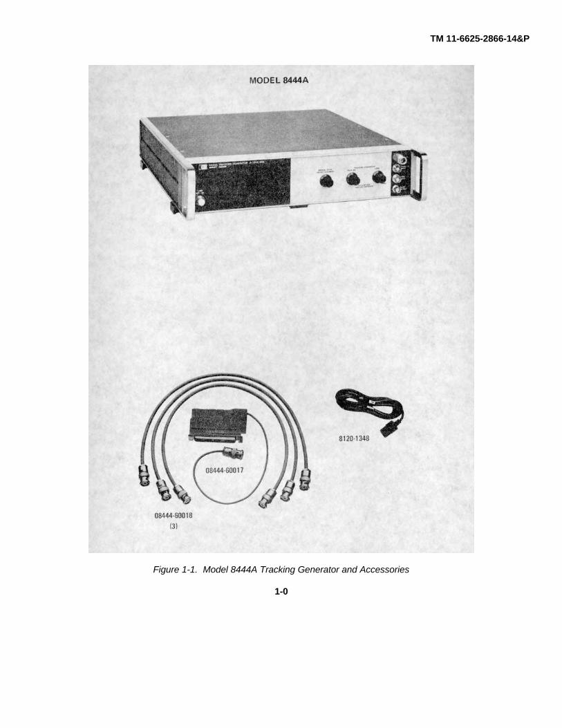
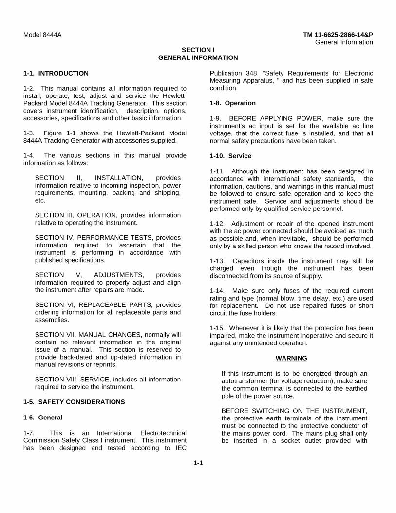
Figure 1-1. Model 8444A Tracking Generator and Accessories
1-0

TM 11-6625-2866-14&PSECTION 0
INTRODUCTION
0-1. SCOPE
This manual describes Generator, Tracking SG-1125/U(Hewlett Packard Model 8444A) and providesinstructions for operation and maintenance.
0-2. INDEXES OF PUBLICATIONS
a. DA Pam 310-4. Refer to the latest issue of DAPam 310-4 to determine whether there are new editions,changes, or additional publications pertaining to theequipment.
b. DA Pam 310-7. Refer to DA Pam 310-7 todetermine whether there are modification work orders(MWO's) pertaining to the equipment.
0-3. MAINTENANCE FORMS, RECORDS, ANDREPORTS
a. Reports of Maintenance and UnsatisfactoryEquipment. Department of the Army forms andprocedures used for equipment maintenance will bethose described by TM 38-750, The Army MaintenanceManagement System.
b. Report of Packaging and Handling Deficiencies.Fill out and forward DD Form 6 (PackagingImprovement Report) as prescribed in AR 700-58/NAVSUPINST 4030.29/AFR 71-13/MCOP4030.29A, and DLAR 4145.8.
c. Discrepancy in Shipment Report (DISREP) (SF
361). Fill out and forward Discrepancy in ShipmentReport (DISREP) (SF 361) as prescribed in AR 55-38/NAVSUPINST 4610.33B/AFR 75-18/MCOP4610.19C and DLAR 4500.15.
0-4. REPORTING EQUIPMENT IMPROVEMENTRECOMMENDATIONS (EIR)
EIR can and must be submitted by anyone who is awareof an unsatisfactory condition with the equipment designor use. It is not necessary to show a new design or list abetter way to perform a procedure; just simply tell whythe design is unfavorable or why a procedure is difficult.EIR may be submitted on SF 368 (Quality DeficiencyReport). Mail direct to Commander, US ArmyCommunications and Electronics Materiel ReadinessCommand, ATTN: DRSEL-ME-MQ, Fort Monmouth, NJ07703. A reply will be furnished to you.
0-5. ADMINISTRATIVE STORAGE
Administrative storage of equipment issued to and usedby Army activities shall be in accordance with paragraph.2-16.
0-6. DESTRUCTION OF ARMY ELECTRONICSMATERIEL
Destruction of Army electronics materiel to preventenemy use shall be in accordance with TM 750-244-2.
0-1
Model 8444A TM 11-6625-2866-14&PGeneral Information
SECTION IGENERAL INFORMATION
1-1. INTRODUCTION
1-2. This manual contains all information required toinstall, operate, test, adjust and service the Hewlett-Packard Model 8444A Tracking Generator. This sectioncovers instrument identification, description, options,accessories, specifications and other basic information.
1-3. Figure 1-1 shows the Hewlett-Packard Model8444A Tracking Generator with accessories supplied.
1-4. The various sections in this manual provideinformation as follows:
SECTION II, INSTALLATION, providesinformation relative to incoming inspection, powerrequirements, mounting, packing and shipping,etc.
SECTION III, OPERATION, provides informationrelative to operating the instrument.
SECTION IV, PERFORMANCE TESTS, providesinformation required to ascertain that theinstrument is performing in accordance withpublished specifications.
SECTION V, ADJUSTMENTS, providesinformation required to properly adjust and alignthe instrument after repairs are made.
SECTION VI, REPLACEABLE PARTS, providesordering information for all replaceable parts andassemblies.
SECTION VII, MANUAL CHANGES, normally willcontain no relevant information in the originalissue of a manual. This section is reserved toprovide back-dated and up-dated information inmanual revisions or reprints.
SECTION VIII, SERVICE, includes all informationrequired to service the instrument.
1-5. SAFETY CONSIDERATIONS
1-6. General
1-7. This is an International ElectrotechnicalCommission Safety Class I instrument. This instrumenthas been designed and tested according to IEC
Publication 348, "Safety Requirements for ElectronicMeasuring Apparatus, " and has been supplied in safecondition.
1-8. Operation
1-9. BEFORE APPLYING POWER, make sure theinstrument's ac input is set for the available ac linevoltage, that the correct fuse is installed, and that allnormal safety precautions have been taken.
1-10. Service
1-11. Although the instrument has been designed inaccordance with international safety standards, theinformation, cautions, and warnings in this manual mustbe followed to ensure safe operation and to keep theinstrument safe. Service and adjustments should beperformed only by qualified service personnel.
1-12. Adjustment or repair of the opened instrumentwith the ac power connected should be avoided as muchas possible and, when inevitable, should be performedonly by a skilled person who knows the hazard involved.
1-13. Capacitors inside the instrument may still becharged even though the instrument has beendisconnected from its source of supply.
1-14. Make sure only fuses of the required currentrating and type (normal blow, time delay, etc.) are usedfor replacement. Do not use repaired fuses or shortcircuit the fuse holders.
1-15. Whenever it is likely that the protection has beenimpaired, make the instrument inoperative and secure itagainst any unintended operation.
WARNING
If this instrument is to be energized through anautotransformer (for voltage reduction), make surethe common terminal is connected to the earthedpole of the power source.
BEFORE SWITCHING ON THE INSTRUMENT,the protective earth terminals of the instrumentmust be connected to the protective conductor ofthe mains power cord. The mains plug shall onlybe inserted in a socket outlet provided with
1-1
Model 8444A TM 11-6625-2866-14&PGeneral Information
protective earth contact. The protection must not benegated by using an extension cord (power cable)without a protective grounding conductor.
Interruption of the protective (grounding) conductor,inside or outside the instrument, or disconnection ofthe protective earth terminal is likely to make thisinstrument dangerous. Intentional interruption of theearth ground is prohibited.
Servicing this instrument often requires that youwork with the instrument's protective coversremoved and with ac power connected. Be verycareful; the energy at many points in the instrumentmay, if contacted, cause personal injury.
With the ac power cable connected, the ac linevoltage is present at the terminals of the power linemodule and at the LINE power switch. Be verycareful. Bodily contact with this voltage can befatal.
CAUTIONS
BEFORE SWITCHING ON THIS INSTRUMENT,make sure instrument's ac input is set to the voltageof the ac power source.
BEFORE SWITCHING ON THIS INSTRUMENT,make sure that all devices connected to theinstrument are connected to the protective earthground.
BEFORE SWITCHING ON THIS INSTRUMENT,make sure the line power (mains) plug is connectedto a threeconductor line power outlet that has aprotective (earth) ground. (Grounding oneconductor of a two-conductor outlet is not sufficient.
BEFORE SWITCHING ON THIS INSTRUMENT,make sure the ac line fuse is of the required currentrating and type (normal-blow, time-delay, etc.).
1-16. INSTRUMENTS COVERED BY MANUAL
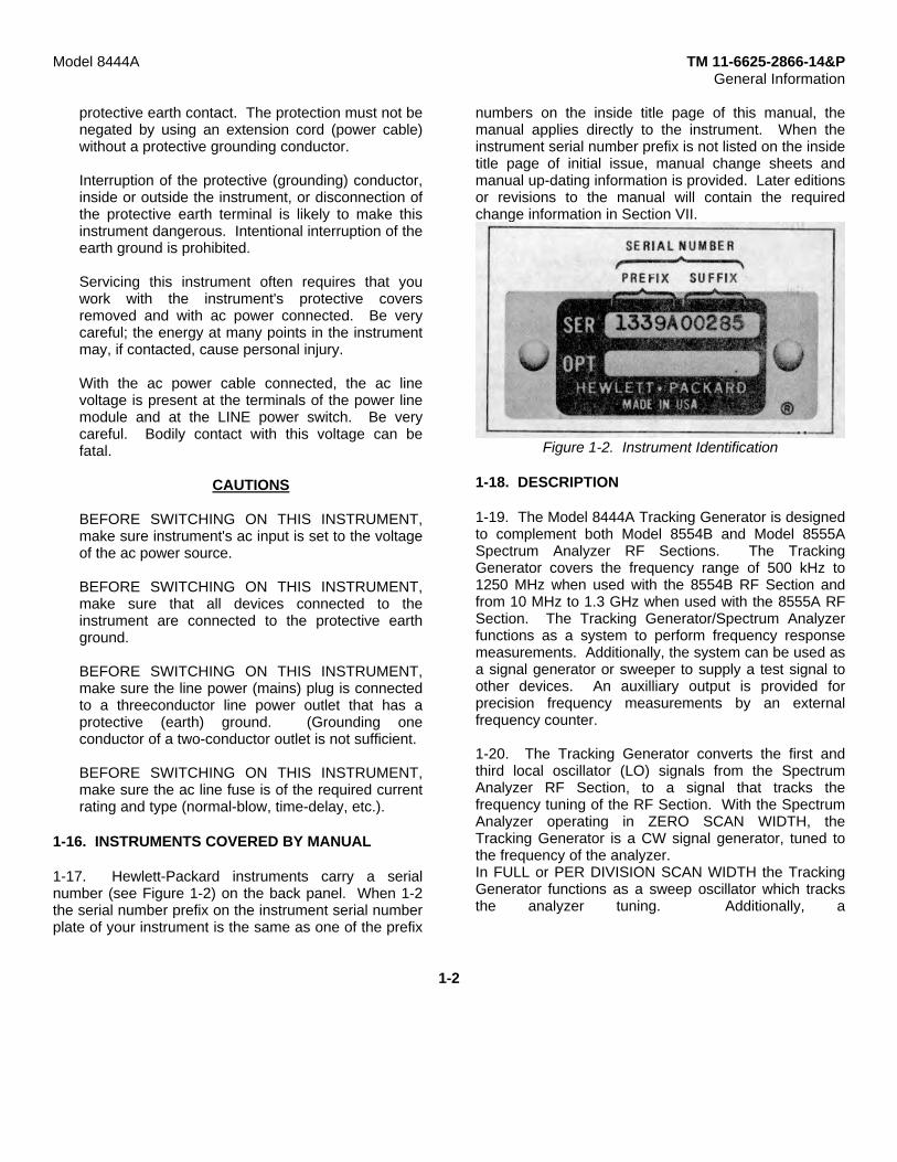
1-17. Hewlett-Packard instruments carry a serialnumber (see Figure 1-2) on the back panel. When 1-2the serial number prefix on the instrument serial numberplate of your instrument is the same as one of the prefix
numbers on the inside title page of this manual, themanual applies directly to the instrument. When theinstrument serial number prefix is not listed on the insidetitle page of initial issue, manual change sheets andmanual up-dating information is provided. Later editionsor revisions to the manual will contain the requiredchange information in Section VII.
Figure 1-2. Instrument Identification
1-18. DESCRIPTION
1-19. The Model 8444A Tracking Generator is designedto complement both Model 8554B and Model 8555ASpectrum Analyzer RF Sections. The TrackingGenerator covers the frequency range of 500 kHz to1250 MHz when used with the 8554B RF Section andfrom 10 MHz to 1.3 GHz when used with the 8555A RFSection. The Tracking Generator/Spectrum Analyzerfunctions as a system to perform frequency responsemeasurements. Additionally, the system can be used asa signal generator or sweeper to supply a test signal toother devices. An auxilliary output is provided forprecision frequency measurements by an externalfrequency counter.
1-20. The Tracking Generator converts the first andthird local oscillator (LO) signals from the SpectrumAnalyzer RF Section, to a signal that tracks thefrequency tuning of the RF Section. With the SpectrumAnalyzer operating in ZERO SCAN WIDTH, theTracking Generator is a CW signal generator, tuned tothe frequency of the analyzer.In FULL or PER DIVISION SCAN WIDTH the TrackingGenerator functions as a sweep oscillator which tracksthe analyzer tuning. Additionally, a
1-2

Model 8444A TM 11-6625-2866-14&PGeneral Information
Table 1-1. System Specifications
These system specifications describe the performance available from thespectrum analyzer-tracking generator system in various types ofapplications. In all cases it is assumed that the spectrum analyzer isequipped with either an 8554B or 8555A Tuning Section, 8552A or 8552BIF Section, 140T or 141T Display Section.
SWEPT FREQUENCY RESPONSE MEASUREMENTS The trackinggenerator is used as a signal source to measure the frequency responseof a device.
Dynamic Range: > 90 dB from spectrum analyzer 1 dB gain compression point to average noise level (approximately -10 dBm to
-100 dBm). Spurious responses not displayed.
Gain Compression: For -10 dBm signal level at the input mixer, gain compression < 1 dB.
Average Noise Level: > -102 dBm with 10 kHz IF bandwidth.
Absolute Amplitude Calibration Range:Spectrum Analyzer: Log: From -122 dBm to +10 dBm, 10 dB/div on a 70 dB display or 2 dB/div on a 16 dB display (8552A has 10 dB/div only).
Linear: From 0.1 pV/div to 100 mV/div (8555A), 20 mV/div (8554B)in a 1, 2 sequence on an 8division display.
Tracking Generator (Drive Level to Test Device): 0 to -10 dBm continuously variable. 0 dBm calibrated to +0.5 dB at 30 MHz.
Frequency Range: 500 kHz to 1250 MHz with 8554B and 10 MHz to 1300 MHz with 8555A.
Scan Width (Determined by Spectrum Analyzer Controls):
Per Division: With 8555A, 16 calibrated scan widths from a 2 kHz/div to 200 MHz/div in a 2, 5, 10 sequence. With 8554B, 15 calibrated scan widths from a 2 kHz/div to 100 MHz/div in 2, 5, 10 sequence.
Full Scan: 0--1250 MHz with 8554B; 0-1300 MHz with 8555A.
Zero Scan: Analyzer is fixed tuned receiver.
Frequency Resolution: 1 kHz.
Stability:Residual FM (peak to peak):Tuning Section Stabilized Unstabilized8554B/8555A 200 Hz 10 kHz
Amplitude Accuracy:System Frequency Response: +1.5 dB.
Tracking Generator Calibration: 0 dBm at 30 MHz to +0.5 dB.
SWEEP/CW GENERATOR
The tracking generator-spectrum analyzer system can be used to supplytest signals for other devices as a sweeper.
Frequency: Controlled by spectrum analyzer. Range is 500 kHz to 1250MHz with the 8554B and 10 MHz to 1300 MHz with the 8555A.Frequency Accuracy: +10 MHz (8554B), +15 MHz (8555A) using
spectrum analyzer tuning dial. Can be substantially improved usingexternal counter output.Spectral Purity:
Residual FM (peak-to-peak):Tuning Section Stabilized Unstabilized8554B/8555A 200 Hz 10 kHz
Harmonic Distortion: 25 dB below outputlevel.
Nonharmonic (spurious) Signals: >40 dB belowoutput level.
Flatness: +/- 0.5 dB.
Long Term Stability: Drift typically less than 30 kHz/hour when stabilized after 2-hour warmup.
Sweep Width: 20 kHz to 1250 MHz (8554B) or 1300 MHz (8555A).Sweep Rates: Selected by Scan Time per Division on spectrum
analyzer. 16 internal scan rates from 0.1 msec/div to 10 sec/div in a1, 2, 5 sequence. Manual Scan is available with the external sweepvoltage from the 8444A or by a front panel control of the 8552B IFSection.
PRECISION FREQUENCY MEASUREMENTSAn external counter output is provided on the 8444A for precisionfrequency measurements. The frequency of unknown signals as well asthe frequency of any point on a frequency response curve can bemeasured. The use of the HP 5300A/5303A Counter is suggested forfrequency measurements to 500 MHz and the HP 5245L/5254C Counterfor measurements to 1300 MHz.
Frequency Accuracy:For unknown signals +10 kHz. (Tracking drift typically 5 kHz/10
min after 2-hour warmup.)For points on frequency response curve. Counteraccuracy ±Residual FM.
Counter Mode of Operation:Manual Scan: Scan determined either by front panel control of
8552B IF Section or by external scan signal provided bythe 8444A.
Zero Scan: Analyzer is fixed tuned receiver. Counter readscenter frequency to accuracy of tracking drift.
Counter Output Level: 0.1 V rms.
GENERAL SPECIFICATIONSTemperature Range: Operation, 0 to 550C, storage -40°C to 75 C.Power: 115V and 230V, 48 to 440 Hz, 12 watts max.
1-3
Model 8444A TM 11-6625-2866-14&PGeneral Information
MANUAL SCAN control on the Tracking Generatorallows manual tuning of the Spectrum Analyzer/TrackingGenerator System. The amplitude of the TrackingGenerator output is adjustable over a 0 to -10 dBmrange by a front panel vernier control. The output levelis calibrated at 30 MHz to 0 +/- 0.5 dBm and maintainedby an automatic level control circuit. Refer to Table 1-1for system performance specifications.
1-21. 8554L RF SECTION MODIFICATIONS
1-22. Hewlett-Packard Model 8554L Spectrum AnalyzerRF Section with serial prefixes 1101A and below requiremodification for Tracking Generator compatibility. Themodification consists of adding two cables to the RFSection. The cables provide front panel access to thefirst and third LO outputs. The modification kit, HP PartNumber 08554-60056, containing all necessary partsand information is available from any Hewlett-PackardSales and Service Office. (A list of Sales and Serviceoffices is contained in the back of this manual.) ServiceNote 8554L-6 containing the modification procedure isincluded with the modification kit. After modification,the Service Note should be filed with the 8554L ServiceManual.
1-23. ACCESSORIES SUPPLIED
1-24. Accessories supplied with the Tracking Generatorare listed in Table 1-2. RF cables, supplied with theTracking Generator, allow operation with either the8554B or 8555A Spectrum Analyzer RF Sections. Thepower cable, supplied with the instrument, is selected attime of shipment. Cable selection is based on shippingdestination. Figure 2-1 illustrates the different power
cable connectors that are currently available.
1-25. OPERATING ACCESSORIES
1-26. In addition to the accessories supplied with theTracking Generator, a Spectrum Analyzer System isrequired to complete the Tracking Generator SpectrumAnalyzer System. The Tracking Generator iscompatible with either the 8554B/8552( )/140-seriesSpectrum Analyzer System or the 8555A/8552( )/140-series Spectrum Analyzer System. Refer to paragraph1-11 for modifications to early model Spectrum AnalyzerSystems. For precision frequency measurements afrequency counter is required for use with the TrackingGenerator/Spectrum Analyzer System. Operatingaccessories are listed in Table 1-4.
1-27. WARRANTY
1-28. The Hewlett-Packard Model 8444A TrackingGenerator is warranted and certified as indicated on theinner front cover of this manual. For further informationcontact the nearest Hewlett Packard Sales and Serviceoffice; addresses are provided at the back of thismanual.
1-29. RECOMMENDED TEST EQUIPMENT
1-30. Table 1-3 lists the test equipment and accessoriesrequired to check, adjust, and repair the TrackingGenerator. If substitute equipment is used, it must meetthe Minimum Specifications listed in Table 1-3.
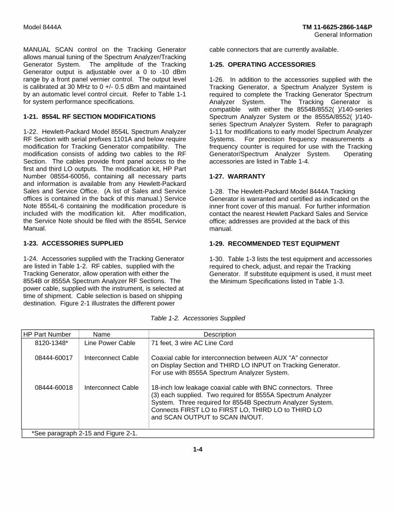
Table 1-2. Accessories Supplied
HP Part Number Name Description8120-1348* Line Power Cable 71 feet, 3 wire AC Line Cord
08444-60017 Interconnect Cable Coaxial cable for interconnection between AUX "A" connectoron Display Section and THIRD LO INPUT on Tracking Generator.For use with 8555A Spectrum Analyzer System.
08444-60018 Interconnect Cable 18-inch low leakage coaxial cable with BNC connectors. Three(3) each supplied. Two required for 8555A Spectrum AnalyzerSystem. Three required for 8554B Spectrum Analyzer System.Connects FIRST LO to FIRST LO, THIRD LO to THIRD LOand SCAN OUTPUT to SCAN IN/OUT.
*See paragraph 2-15 and Figure 2-1.
1-4

Model 8444A TM 11-6625-2866-14&PGeneral Information
Table 1-3. Test Equipment and Accessories (1 of 3)
1-5

Model 8444A TM 11-6625-2866-14&PGeneral Information
Table 1-3. Test Equipment and Accessories (2 of 3)
1-6

Model 8444A TM 11-6625-2866-14&PGeneral Information
Table 1-3. Test Equipment and Accessories (3 of 3)
Table 1-4. Operating Accessories
1-7/(1-8)

Model 8444A TM 11-6625-2866-14&PInstallation
SECTION IIINSTALLATION
2-1. INITIAL INSPECTION
2-2. Mechanical Check
2-3. Check the shipping carton for evidence of damageimmediately after receipt. If there is any visible damageto the carton, request the carrier's agent be presentwhen the instrument is unpacked. Inspect theinstrument for physical damage such as bent or brokenparts and dents or scratches. If damage is found referto paragraph 2-6 for recommended claim procedures. Ifthe instrument appears to be undamaged, perform theelectrical check (see paragraph 2-4). The packagingmaterial should be retained for possible future use.
2-4. Electrical Check
2-5. The electrical check consists of following theperformance test procedures listed in Section IV. Theseprocedures allow the operator to determine that theinstrument is, or is not, operating within thespecifications listed in Table 1-1. The initialperformance and accuracy of the instrument arecertified as stated on the inside front cover of thismanual. If the instrument does not operate as specified,refer to paragraph 2-6 for the recommended claimprocedure.
2-6. CLAIMS FOR DAMAGE
2-7. If physical damage is found when the instrument isunpacked, notify the carrier and the nearest Hewlett-Packard Sales and Service office immediately. TheSales and Service office will arrange for repair orreplacement without waiting for a claim to be settledwith the carrier.
2-8. The warranty statement for the instrument is on theinside front cover of this manual. Contact the nearestSales and Service office for information about warrantyclaims.
2-9. PREPARATION FOR USE
CAUTION
Before applying power, check the power selectorswitch on the Tracking Generator input powermodule (rear panel) for proper position (115 or230 volts).
2-10. Power Requirements
2-11. The Tracking Generator can be operated from a48to 440-hertz input line that supplies either 115or 230-volt (+10% in each case) power. Consumed power isnormally less than 15 watts.
2-12. The 115/230 power selector switch on the rearpanel line power module must be set to agree with theavailable line voltage. The selector switch is locatedbelow the fuse holder and fuse extractor lever. Anarrow on the selector switch points to callouts listing theline input voltage and fuse amperage rating. To changethe position of the selector switch it is necessary toremove the power cable, slide the protective cover tothe left and lift the fuse extractor before the switch canbe changed. With the fuse extractor extended, pressdown and toward the desired direction. Replace fusewith a fuse of the amperage rating for the selectedposition. See Section VI for replacement HP PartNumbers. The instrument is normally shipped with fuseinstalled for 115-volt operation.
2-13. Power Cable
2-14. To protect operating personnel, the NationalElectrical Manufacturers Association (NEMA) and theInternational Electrotechnical Commission (IEC)recommends that the instrument panel and cabinet begrounded. The Tracking Generator is equipped with athree-conductor power cable; the third conductor is theground conductor and when the cable is plugged into anappropriate receptacle, the instrument is grounded. Topreserve the protection feature when operating theinstrument from a two-contact outlet, use a three-prongto two-prong adapter and connect the green or green/yellow lead on the adapter to ground.
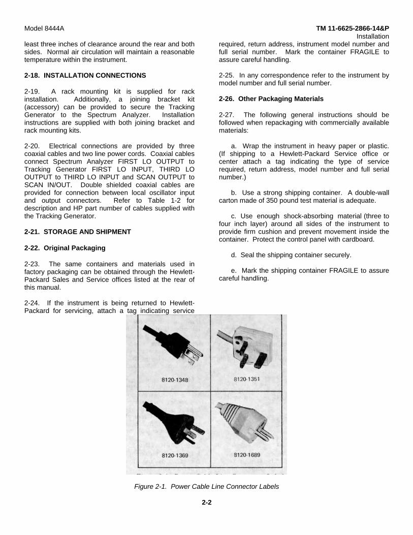
2-15. Power cables are selected for shipment with eachinstrument; with a line connector plug to match thestandard power cord for the country of destination on thepurchase order. A label indicating the power cableinside is affixed to the packing case. Figure 2-1indicates the connector plugs and the HP part numbersfor the various available power cables and plugs.
2-16. OPERATING ENVIRONMENT
2-17. The Tracking Generator does not require forcedair cooling when operating at temperatures from 0 to55°C (32 to 131°F). When operating the instrument,choose a location which will provide at
2-1
Model 8444A TM 11-6625-2866-14&PInstallation
least three inches of clearance around the rear and bothsides. Normal air circulation will maintain a reasonabletemperature within the instrument.
2-18. INSTALLATION CONNECTIONS
2-19. A rack mounting kit is supplied for rackinstallation. Additionally, a joining bracket kit(accessory) can be provided to secure the TrackingGenerator to the Spectrum Analyzer. Installationinstructions are supplied with both joining bracket andrack mounting kits.
2-20. Electrical connections are provided by threecoaxial cables and two line power cords. Coaxial cablesconnect Spectrum Analyzer FIRST LO OUTPUT toTracking Generator FIRST LO INPUT, THIRD LOOUTPUT to THIRD LO INPUT and SCAN OUTPUT toSCAN IN/OUT. Double shielded coaxial cables areprovided for connection between local oscillator inputand output connectors. Refer to Table 1-2 fordescription and HP part number of cables supplied withthe Tracking Generator.
2-21. STORAGE AND SHIPMENT
2-22. Original Packaging
2-23. The same containers and materials used infactory packaging can be obtained through the Hewlett-Packard Sales and Service offices listed at the rear ofthis manual.
2-24. If the instrument is being returned to Hewlett-Packard for servicing, attach a tag indicating service
required, return address, instrument model number andfull serial number. Mark the container FRAGILE toassure careful handling.
2-25. In any correspondence refer to the instrument bymodel number and full serial number.
2-26. Other Packaging Materials
2-27. The following general instructions should befollowed when repackaging with commercially availablematerials:
a. Wrap the instrument in heavy paper or plastic.(If shipping to a Hewlett-Packard Service office orcenter attach a tag indicating the type of servicerequired, return address, model number and full serialnumber.)
b. Use a strong shipping container. A double-wallcarton made of 350 pound test material is adequate.
c. Use enough shock-absorbing material (three tofour inch layer) around all sides of the instrument toprovide firm cushion and prevent movement inside thecontainer. Protect the control panel with cardboard.
d. Seal the shipping container securely.
e. Mark the shipping container FRAGILE to assurecareful handling.
Figure 2-1. Power Cable Line Connector Labels
2-2
Model 8444A TM 11-6625-2866-14&POperation
SECTION IIIOPERATION
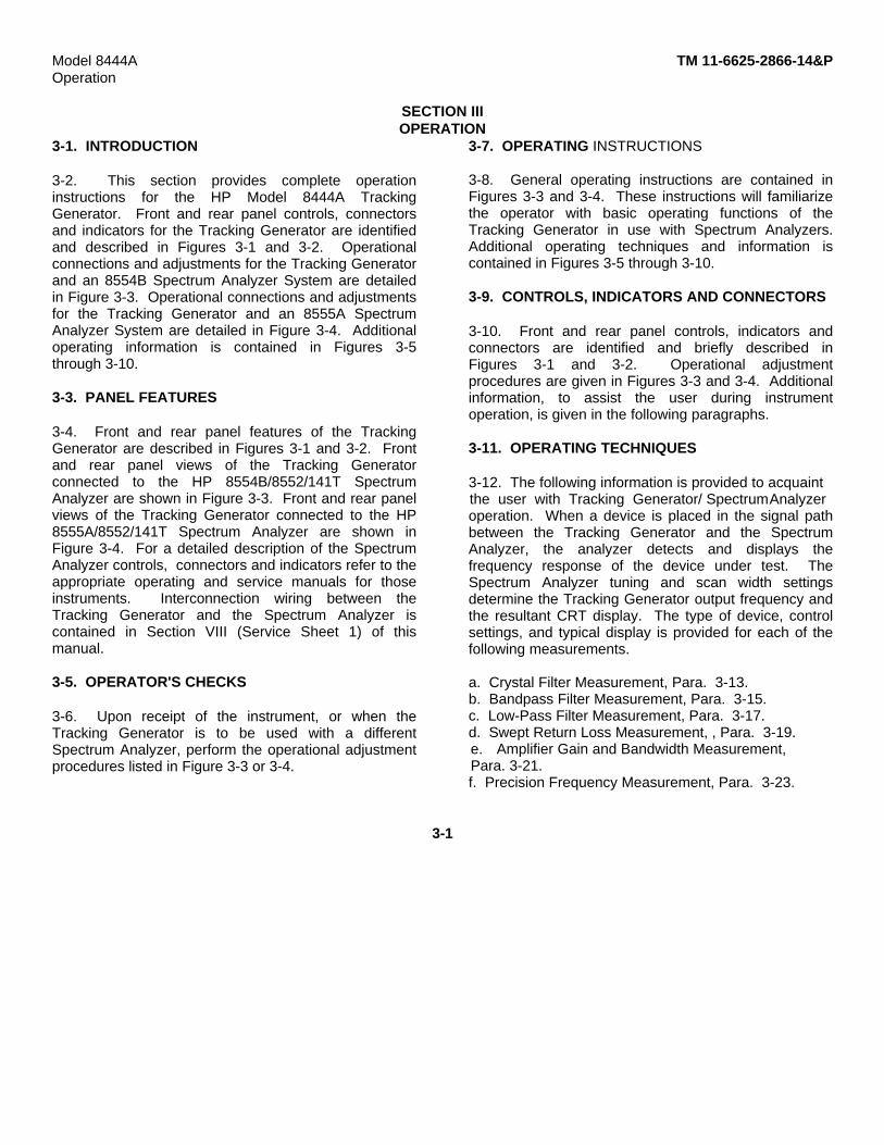
3-1. INTRODUCTION
3-2. This section provides complete operationinstructions for the HP Model 8444A TrackingGenerator. Front and rear panel controls, connectorsand indicators for the Tracking Generator are identifiedand described in Figures 3-1 and 3-2. Operationalconnections and adjustments for the Tracking Generatorand an 8554B Spectrum Analyzer System are detailedin Figure 3-3. Operational connections and adjustmentsfor the Tracking Generator and an 8555A SpectrumAnalyzer System are detailed in Figure 3-4. Additionaloperating information is contained in Figures 3-5through 3-10.
3-3. PANEL FEATURES
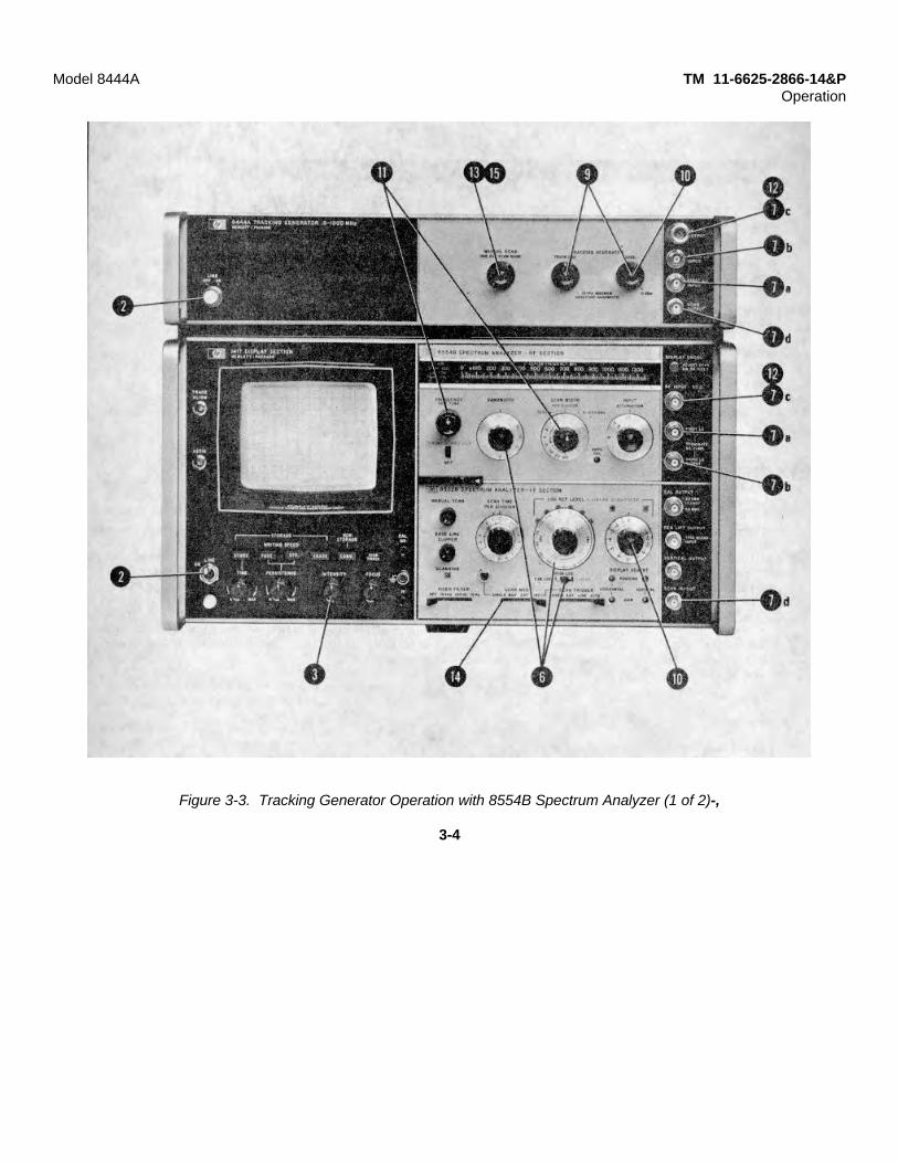
3-4. Front and rear panel features of the TrackingGenerator are described in Figures 3-1 and 3-2. Frontand rear panel views of the Tracking Generatorconnected to the HP 8554B/8552/141T SpectrumAnalyzer are shown in Figure 3-3. Front and rear panelviews of the Tracking Generator connected to the HP8555A/8552/141T Spectrum Analyzer are shown inFigure 3-4. For a detailed description of the SpectrumAnalyzer controls, connectors and indicators refer to theappropriate operating and service manuals for thoseinstruments. Interconnection wiring between theTracking Generator and the Spectrum Analyzer iscontained in Section VIII (Service Sheet 1) of thismanual.
3-5. OPERATOR'S CHECKS
3-6. Upon receipt of the instrument, or when theTracking Generator is to be used with a differentSpectrum Analyzer, perform the operational adjustmentprocedures listed in Figure 3-3 or 3-4.
3-7. OPERATING INSTRUCTIONS
3-8. General operating instructions are contained inFigures 3-3 and 3-4. These instructions will familiarizethe operator with basic operating functions of theTracking Generator in use with Spectrum Analyzers.Additional operating techniques and information iscontained in Figures 3-5 through 3-10.
3-9. CONTROLS, INDICATORS AND CONNECTORS
3-10. Front and rear panel controls, indicators andconnectors are identified and briefly described inFigures 3-1 and 3-2. Operational adjustmentprocedures are given in Figures 3-3 and 3-4. Additionalinformation, to assist the user during instrumentoperation, is given in the following paragraphs.
3-11. OPERATING TECHNIQUES
3-12. The following information is provided to acquaintthe user with Tracking Generator/ SpectrumAnalyzeroperation. When a device is placed in the signal pathbetween the Tracking Generator and the SpectrumAnalyzer, the analyzer detects and displays thefrequency response of the device under test. TheSpectrum Analyzer tuning and scan width settingsdetermine the Tracking Generator output frequency andthe resultant CRT display. The type of device, controlsettings, and typical display is provided for each of thefollowing measurements.
a. Crystal Filter Measurement, Para. 3-13.b. Bandpass Filter Measurement, Para. 3-15.c. Low-Pass Filter Measurement, Para. 3-17.d. Swept Return Loss Measurement, , Para. 3-19.e. Amplifier Gain and Bandwidth Measurement,Para. 3-21.f. Precision Frequency Measurement, Para. 3-23.
3-1

Model 8444A TM 11-6625-2866-14&POperation
FRONT PANEL
1. LINE - ON/OFF. Controls primary power to TrackingGenerator. Light glows when switch is energized.Type A1H bulb. For access to bulb, switch to OFFand pull button straight out.
2. MANUAL SCAN. Provides manual tuning ofSpectrum Analyzer. Controls voltage level at SCANOUTPUT (8) below. Scan trace on CRT determinedby position of MANUAL SCAN control. For MANUALSCAN operation, connect cable between TrackingGenerator SCAN OUTPUT and Spectrum AnalyzerSCAN IN/OUT. Set Spectrum Analyzer SCANMODE switch to EXT. Vary MANUAL SCAN controlto tune analyzer through selected SCAN WIDTH.
3. TRACK ADJ. Adjusts frequency of 1.55 GHzoscillator in Tracking Generator so that the RFOUTPUT (5) tracks the frequency tuning of theSpectrum Analyzer. Control adjusted for maximumamplitude indication of trace on CRT display. Tenturn control provides adjustment of frequency over arange of approximately 4 MHz.
4. LEVEL. Adjusts Tracking Generator RF OUTPUT(5) level over range of 0 to -10 dBm. Levelcalibrated
for 0 dBm at 30 MHz with accuracy of +0.5 dB. SetLEVEL control to 0 dBm for calibrated CRT displayon Spectrum Analyzer.
5. RF OUTPUT. Type N Connector - TrackingGenerator RF output connector. Frequency adjustedto track tuning of Spectrum Analyzer by TRACK ADJ(3). Output level adjusted by LEVEL (4).
6. THIRD LO INPUT. Type BNC connector Input forSpectrum Analyzer third LO (500 MHz). Normallyused with 8554B RF Section. Parallel with rear panelTHIRD LO INPUT which is normally used with 8555ARF Section.
7. FIRST LO INPUT. Type BNC connector-Input forSpectrum Analyzer first LO (2.05 - 3.3 GHz with8554L RF Section) - (2.05 - 4.1 GHz with 8555A RFSection).
8. SCAN OUTPUT. Type BNC connector. Manualtune voltage to Spectrum Analyzer (0 to 10 Vdc).Voltage level controlled by position of MANUALSCAN (2).
Figure 3-1. Model 8444A Tracking Generator Front Panel Controls, Indicators and Connectors
3-2
Model 8444A TM 11-6625-2866-14&POperation
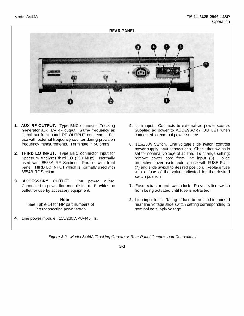
REAR PANEL
1. AUX RF OUTPUT. Type BNC connector TrackingGenerator auxiliary RF output. Same frequency assignal out front panel RF OUTPUT connector. Foruse with external frequency counter during precisionfrequency measurements. Terminate in 50 ohms.
2. THIRD LO INPUT. Type BNC connector Input forSpectrum Analyzer third LO (500 MHz). Normallyused with 8555A RF Section. Parallel with frontpanel THIRD LO INPUT which is normally used with8554B RF Section.
3. ACCESSORY OUTLET. Line power outlet.Connected to power line module input. Provides acoutlet for use by accessory equipment.
NoteSee Table 14 for HP part numbers of
interconnecting power cords.
4. Line power module. 115/230V, 48-440 Hz.
5. Line input. Connects to external ac power source.Supplies ac power to ACCESSORY OUTLET whenconnected to external power source.
6. 115/230V Switch. Line voltage slide switch; controlspower supply input connections. Check that switch isset for nominal voltage of ac line. To change setting:remove power cord from line input (5) , slideprotective cover aside, extract fuse with FUSE PULL(7) and slide switch to desired position. Replace fusewith a fuse of the value indicated for the desiredswitch position.
7. Fuse extractor and switch lock. Prevents line switchfrom being actuated until fuse is extracted.
8. Line input fuse. Rating of fuse to be used is markednear line voltage slide switch setting corresponding tonominal ac supply voltage.
Figure 3-2. Model 8444A Tracking Generator Rear Panel Controls and Connectors
3-3
Model 8444A TM 11-6625-2866-14&POperation
Figure 3-3. Tracking Generator Operation with 8554B Spectrum Analyzer (1 of 2)-,
3-4
Model 8444A TM 11-6625-2866- 14&POperation
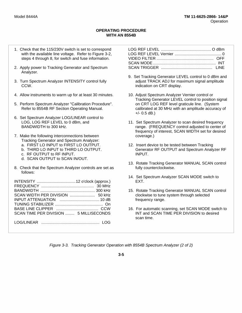
OPERATING PROCEDUREWITH AN 8554B
1. Check that the 115/230V switch is set to correspondwith the available line voltage. Refer to Figure 3-2,steps 4 through 8, for switch and fuse information.
2. Apply power to Tracking Generator and SpectrumAnalyzer.
3. Turn Spectrum Analyzer INTENSITY control fullyCCW.
4. Allow instruments to warm up for at least 30 minutes.
5. Perform Spectrum Analyzer "Calibration Procedure".Refer to 8554B RF Section Operating Manual.
6. Set Spectrum Analyzer LOG/LINEAR control toLOG, LOG REF LEVEL to 0 dBm, andBANDWIDTH to 300 kHz.
7. Make the following interconnections betweenTracking Generator and Spectrum Analyzer:a. FIRST LO INPUT to FIRST LO OUTPUT.b. THIRD LO INPUT to THIRD LO OUTPUT.c. RF OUTPUT to RF INPUT.d. SCAN OUTPUT to SCAN IN/OUT.
8. Check that the Spectrum Analyzer controls are set asfollows:
INTENSITY ..................................12 o'clock (approx.)FREQUENCY .............................................. 30 MHzBANDWIDTH ................................................ 300 kHzSCAN WIDTH PER DIVISION ...................... 50 kHzINPUT ATTENUATION ................................... 10 dBTUNING STABILIZER .......................................... OnBASE LINE CLIPPER ..................................... CCWSCAN TIME PER DIVISION ........ 5 MILLISECONDS
LOG/LINEAR ................................................... LOG
LOG REF LEVEL ............................................ O dBmLOG REF LEVEL Vernier ......................................... 0VIDEO FILTER .................................................. OFFSCAN MODE ....................................................... INTSCAN TRIGGER ............................................. LINE
9. Set Tracking Generator LEVEL control to 0 dBm andadjust TRACK ADJ for maximum signal amplitudeindication on CRT display.
10. Adjust Spectrum Analyzer Vernier control orTracking Generator LEVEL control to position signalon CRT LOG REF level graticule line. (Systemcalibrated at 30 MHz with an amplitude accuracy of+/- 0.5 dB.)
11. Set Spectrum Analyzer to scan desired frequencyrange. (FREQUENCY control adjusted to center offrequency of interest, SCAN WIDTH set for desiredcoverage.)
12. Insert device to be tested between TrackingGenerator RF OUTPUT and Spectrum Analyzer RFINPUT.
13. Rotate Tracking Generator MANUAL SCAN controlfully counterclockwise.
14. Set Spectrum Analyzer SCAN MODE switch toEXT.
15. Rotate Tracking Generator MANUAL SCAN controlclockwise to tune system through selectedfrequency range.
16. For automatic scanning, set SCAN MODE switch toINT and SCAN TIME PER DIVISION to desiredscan time.
Figure 3-3. Tracking Generator Operation with 8554B Spectrum Analyzer (2 of 2)
3-5
Model 8444A TM 11-6625-2866-14&POperation
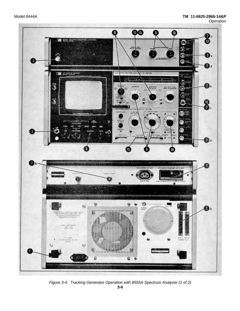
Figure 3-4. Tracking Generator Operation with 8555A Spectrum Analyzer (1 of 2)3-6
Model 8444A TM 11-6625-2866-14&POperation
OPERATING PROCEDUREWITH AN 8555A
1. Check that the 115/230 switch is set to correspondwith the available line voltage. Refer to Figure 3-2,steps 4 through 8, for switch and fuse information.
2. Apply power to Tracking Generator and SpectrumAnalyzer.
3. Turn Spectrum Analyzer INTENSITY control fullyCCW.
4. Allow instruments to warm up for at least 30 minutes.
5. Perform Spectrum Analyzer Operational Adjustments(30 MHz Calibration). Refer to 8555A RF SectionOperating and Service Manual.
6. Set Spectrum Analyzer LOG/LINEAR control toLOG, LOG REF LEVEL to 0 dBm, andBANDWIDTH to 300 kHz.
7. Make the following interconnections betweenTracking Generator and Spectrum Analyzer:
a. FIRST LO INPUT to FIRST LO OUTPUT.b. THIRD LO INPUT to THIRD LO OUTPUT (rear
panel connections).c. RF OUTPUT to INPUT.d. SCAN OUTPUT to SCAN IN/OUT.
8. Check that the Spectrum Analyzer controls are set asfollows:
INTENSITY ................................ 12 o'clock (approx.)BAND ............................................ n=l- (2.05 GHz IF)FREQUENCY .............................................. 30 MHzBANDWIDTH .............................................. 300 kHzSCAN WIDTH PER DIVISION .................... 100 kHzINPUT ATTENUATION ..................................... 20 dBTUNING STABILIZER ..........................................ONSIGNAL IDENTIFIER ........................................ OFFBASE LINE CLIPPER ..................................... CCWSCAN TIME PER DIVISION ...... 10 MILLISECONDS
LOG/LINEAR ................................................... LOGLOG REF LEVEL ......................................... O dBmLOG REF LEVEL Vernier ......................................... 0VIDEO FILTER ................................................... OFFSCAN MODE ..................................................... INTSCAN TRIGGER ............................... LINE or AUTO
9. Set Tracking Generator LEVEL control to 0 dBm andadjust TRACK ADJ for maximum signal amplitudeindication on CRT display.
10. Adjust Spectrum Analyzer Vernier control orTracking Generator LEVEL control to position signalon CRT LOG REF level graticule line. (Systemcalibrated at 30 MHz with an amplitude accuracy of10.5 dB.)
11. Set Spectrum Analyzer to scan desired frequencyrange. (FREQUENCY control adjusted to center offrequency of interest, SCAN WIDTH set for desiredcoverage.)
12. Insert device to be tested between TrackingGenerator RF OUTPUT and Spectrum Analyzer RFINPUT.
13. Rotate Tracking Generator MANUAL SCAN controlfully counterclockwise.
14. Set Spectrum Analyzer SCAN MODE switch toEXT.
15. Rotate Tracking Generator MANUAL SCAN controlclockwise to tune system through selectedfrequency range.
16. For automatic scanning, set SCAN MODE switch toINT and SCAN TIME PER DIVISION to desiredscan time.
Figure 3-4. Tracking Generator Operation with 8555A Spectrum Analyzer (2 of 2)
3-7
Model 8444A TM 11-6625-2866 -14&POperation
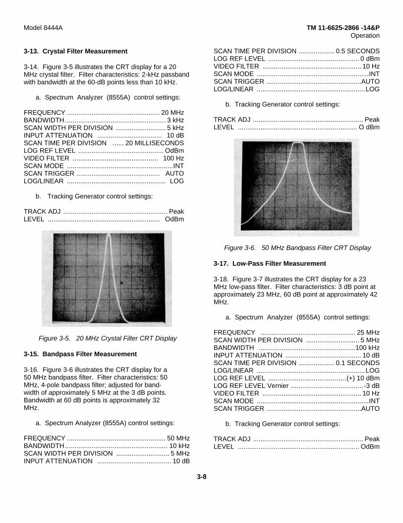
3-13. Crystal Filter Measurement
3-14. Figure 3-5 illustrates the CRT display for a 20MHz crystal filter. Filter characteristics: 2-kHz passbandwith bandwidth at the 60-dB points less than 10 kHz.
a. Spectrum Analyzer (8555A) control settings:
FREQUENCY ................................................. 20 MHzBANDWIDTH..................................................... 3 kHzSCAN WIDTH PER DIVISION .......................... 5 kHzINPUT ATTENUATION .................................. 10 dBSCAN TIME PER DIVISION ...... 20 MILLISECONDSLOG REF LEVEL ............................................. OdBmVIDEO FILTER ............................................. 100 HzSCAN MODE ........................................................INTSCAN TRIGGER ............................................ AUTOLOG/LINEAR .................................................... LOG
b. Tracking Generator control settings:
TRACK ADJ ....................................................... PeakLEVEL ........................................................... OdBm
Figure 3-5. 20 MHz Crystal Filter CRT Display
3-15. Bandpass Filter Measurement
3-16. Figure 3-6 illustrates the CRT display for a50 MHz bandpass filter. Filter characteristics: 50MHz, 4-pole bandpass filter; adjusted for band-width of approximately 5 MHz at the 3 dB points.Bandwidth at 60 dB points is approximately 32MHz.
a. Spectrum Analyzer (8555A) control settings:
FREQUENCY .................................................... 50 MHzBANDWIDTH...................................................... 10 kHzSCAN WIDTH PER DIVISION ............................ 5 MHzINPUT ATTENUATION ....................................... 10 dB
SCAN TIME PER DIVISION ................... 0.5 SECONDSLOG REF LEVEL ................................................ 0 dBmVIDEO FILTER .................................................... 10 HzSCAN MODE ...........................................................INTSCAN TRIGGER ..................................................AUTOLOG/LINEAR .........................................................LOG
b. Tracking Generator control settings:
TRACK ADJ .......................................................... PeakLEVEL ............................................................... O dBm
Figure 3-6. 50 MHz Bandpass Filter CRT Display
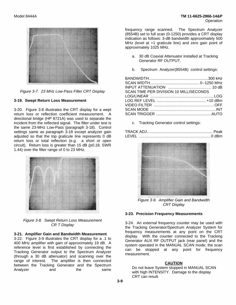
3-17. Low-Pass Filter Measurement
3-18. Figure 3-7 illustrates the CRT display for a 23MHz low-pass filter. Filter characteristics: 3 dB point atapproximately 23 MHz, 60 dB point at approximately 42MHz.
a. Spectrum Analyzer (8555A) control settings:
FREQUENCY .................................................. 25 MHzSCAN WIDTH PER DIVISION ............................ 5 MHzBANDWIDTH ...................................................100 kHzINPUT ATTENUATION ........................................ 10 dBSCAN TIME PER DIVISION ................... 0.1 SECONDSLOG/LINEAR .........................................................LOGLOG REF LEVEL .........................................(+) 10 dBmLOG REF LEVEL Vernier ...................................... -3 dBVIDEO FILTER .................................................... 10 HzSCAN MODE ...........................................................INTSCAN TRIGGER ..................................................AUTO
b. Tracking Generator control settings:
TRACK ADJ .......................................................... PeakLEVEL ................................................................ OdBm
3-8
Model 8444A TM 11-6625-2866-14&POperation
Figure 3-7. 23 MHz Low-Pass Filter CRT Display
3-19. Swept Return Loss Measurement
3-20. Figure 3-8 illustrates the CRT display for a weptreturn loss or reflection coefficient measurement. Adirectional bridge (HP 8721A) was used to separate theincident from the reflected signal. The filter under test isthe same 23-MHz Low-Pass (paragraph 3-18). Controlsettings same as paragraph 3-18 except analyzer gainadjusted so that the top graticule line represents 0 dBreturn loss or total reflection (e.g. a short or opencircuit). Return loss is greater than 15 dB (p0.18, SWR1.44) over the filter range of 0 to 23 MHz.
Figure 3-8. Swept Return Loss MeasurementCR T Display
3-21. Amplifier Gain and Bandwidth Measurement3-22. Figure 3-9 illustrates the CRT display for a .1 to400 MHz amplifier with gain of approximately 19 dB. Areference level is first established by connecting theTracking Generator output to the Spectrum Analyzer(through a 30 dB attenuator) and scanning over therange of interest. The amplifier is then connectedbetween the Tracking Generator and the SpectrumAnalyzer and the same
frequency range scanned. The Spectrum Analyzer(8554B) set to full scan (0-1250) provides a CRT displayindication as follows: 3-dB bandwidth approximately 500MHz (level at +1 graticule line) and zero gain point ofapproximately 1025 MHz.
a. 30 dB Coaxial Attenuator installed at TrackingGenerator RF OUTPUT.
b. Spectrum Analyzer(8554B) control settings:
BANDWIDTH.....................................................300 kHzSCAN WIDTH............................................ 0--1250 MHzINPUT ATTENUATION ....................................... 10 dBSCAN TIME PER DIVISION 10 MILLISECONDSLOG/LINEAR .........................................................LOGLOG REF LEVEL ............................................ +10 dBmVIDEO FILTER ...................................................... OFFSCAN MODE ...........................................................INTSCAN TRIGGER ..................................................AUTO
c. Tracking Generator control settings:
TRACK ADJ........................................................... PeakLEVEL ................................................................ 0 dBm
Figure 3-9. Amplifier Gain and BandwidthCRT Display
3-23. Precision Frequency Measurements
3-24. An external frequency counter may be used withthe Tracking Generator/Spectrum Analyzer System forfrequency measurements at any point on the CRTdisplay. With the counter connected to the TrackingGenerator AUX RF OUTPUT jack (rear panel) and thesystem operated in the MANUAL SCAN mode; the scancan be stopped at any point for frequencymeasurement.
CAUTIONDo not leave System stopped in MANUAL SCANwith high INTENSITY. Damage to the displayCRT can result.
3-9

Model 8444A TM 11-6625-2866-14&POperation
Figure 3-10 illustrates frequency measurement at the 30dB point on a low-pass filter.
a. Spectrum Analyzer (8554B) control settings:
FREQUENCY ................................................... 50 MHzBANDWIDTH ....................................................300 kHzSCAN WIDTH PER DIVISION .......................... 10 MHzINPUT ATTENUATION ......................................... 10dBSCAN TIME PER DIVISION ........... 10 MILLISECONDSLOG REF LEVEL ................................................ 0 dBmLOG/LINEAR .........................................................LOGVIDEO FILTER ...................................................... OFFSCAN MODE ...........................................................INTSCAN TRIGGER ..................................................AUTO
b. Tracking Generator control settings:
TRACK ADJ .......................................................... PeakLEVEL ................................................................ 0 dBmMANUAL SCAN ....................................................CCW
c. Connect unit under test between TrackingGenerator RF OUTPUT and Spectrum AnalyzerRF INPUT.
d. Connect Tracking Generator AUX RF OUTPUTto Frequency Counter input.
e. Connect. Tracking Generator SCAN OUTPUT toSpectrum Analyzer SCAN IN/OUT.
f. Connect Tracking Generator FIRST LO INPUT toSpectrum Analyzer FIRST LO OUTPUT and THIRD LOINPUT to THIRD LO OUTPUT.
g. Note point of interest on CRT display.
h. Set Spectrum Analyzer SCAN MODE to EXTand rotate Tracking Generator MANUAL SCAN controlclockwise to point of interest.
i. Note and record frequency.
j. Set Spectrum Analyzer SCAN MODE to INT.
Note
The CRT trace (dot) can be moved in eitherdirection by the Tracking Generator MANUALSCAN control. For best' frequency accuracy,approach frequency measurement point whiletuning the MANUAL SCAN control in theclockwisedirection.
Figure 3-10. Precision Frequency Measurement CRTDisplay
3-10

Model 8444A TM 11-6625-2866-14&PPerformance Tests
SECTION IVPERFORMANCE TESTS
4-1. INTRODUCTION
4-2. This section contains preset adjustment proceduresand performance tests for the Model 8444A TrackingGenerator and Model 8554L or 8555A/ 8552B/141TSpectrum Analyzer System. Preset adjustments for the8444A/8554B/8552B/141T system are given inparagraph 4-7. Preset adjustments for the8444A/8555A/8552B/141T are given in paragraph 4-9.Perform the preset adjustment procedures for theappropriate system prior to accomplishing theperformance tests. Procedures for verifying that theinstruments meet specifications are given in paragraphs4-16 through 4-20.
4-3. EQUIPMENT REQUIRED
4-4. Test equipment and accessories for performance(P), adjustment (A) and troubleshooting (T) are listed inTable 1-3. Critical specifications and/ or requiredfeatures for the test equipment and accessories arecontained in the table. Each performance test lists therequired test equipment and contains an illustrated testequipment setup.
4-5. FRONT PANEL CHECKS
4-6. Before proceeding to the performance tests, theinstruments must be adjusted and all controls set asspecified in the preset adjustment procedures for theappropriate system (8554B/8555A). The instrumentsshould perform as called out in the preset adjustmentprocedures before going on to the performance tests.
4-7. Preset Adjustments (8554B/8552B/141T/ 8444ASystem)
4-8. Procedure:
a. Apply power to Tracking Generator andSpectrum Analyzer.
b. Turn Spectrum Analyzer INTENSITY control fullyCCW.
c. Allow instruments to warm up for at least 30minutes.
d. Perform Spectrum Analyzer 30 MHz calibrationprocedure. Refer to 8554B RF Section OperatingManual.
e. Connect Spectrum Analyzer FIRST LO OUTPUTto Tracking Generator FIRST LOINPUT.
f. Connect Spectrum Analyzer THIRD LO OUTPUTto Tracking Generator THIRD LO INPUT.
g. Connect Tracking Generator RF OUTPUT toSpectrum Analyzer RF INPUT.
h. Connect Tracking Generator SCAN OUTPUT toSpectrum Analyzer SCAN IN/OUT.
i. Set Spectrum Analyzer controls as follows:
INTENSITY .....................................12 o'clock (approx.)FREQUENCY ................................................... 30 MHzBANDWIDTH ....................................................300 kHzSCAN WIDTH ........................................PER DIVISIONSCAN WIDTH PER DIVISION ...........................200 kHzINPUT ATTENUATION ........................................ 20 dBTUNING STABILIZER ...............................................OnBASE LINE CLIPPER ...........................................CCWSCAN TIME PER DIVISION ........... 10 MILLISECONDSLOG/LINEAR ...............................................10 dB LOGLOG REF LEVEL ................................................ OdBmLOG REF LEVEL Vernier ............................................ 0VIDEO FILTER ...................................................... OFFSCAN MODE ...........................................................INTSCAN TRIGGER .....................................LINE or AUTO
j. Set Tracking Generator controls as follows:
MANUALSCAN ....................................................CCWLEVEL ................................................................ OdBm
k. Adjust TRACK ADJ control for maximumamplitude of trace on CRT display.
l. If trace is not within +0.5 dB of LOG REF levelgraticule line repeat Spectrum Analyzer calibrationprocedure.
m. Reconnect Tracking Generator RF OUTPUT toSpectrum Analyzer RF INPUT and adjust TRACK ADJfor maximum signal amplitude.
n. Rotate LEVEL control fully counterclockwise (-10dBm) and note signal level on CRT display.
-10 to --12 dBm
4-1
Model 8444A TM 11-6625-2866-14&PPerformance Tests
o. If the signal level is off more than ±0.5 dB at the 0dBm point or not within -10 to -12 dBm with the I, L, VELcontrol fully counterclockwise, refer to paragraph 4-16,Output Level Performance Check, a:1 -13 for LEVELcontrol calibration procedure.
4-9. Preset Adjustments (8555A/8552B/141T/ 8444ASystem)
4-10. Procedure:
a. Apply power to Tracking Generator andSpectrum Analyzer.
b. Turn Spectrum Analyzer INTENSITY , controlfully CCW.
c. Allow instruments to warm up for at least 30minutes.
d. Per, form Spectrum Analyzer OperationalAdjustments (30 MHz Calibration). Refer to o55t5 ARF' Section Operating and Service Manual.
e. Connect Spectrum Analyzer FIRST LOOUTPUT'l1, -. Tracking Generator FIRST LO INPUIT.
f. Connect Spectrum Analyzer THIRD LO OUTPUTto Tracking Generator THIRD LO INPUT (rear panelconnections).
g. Connect Tracking Generator RF OUTPUT toSpectrum .Analyzer INPUT.
h. Connect '[racking Generator SCAN OUTPUT toPUT to Spectrum Analyzer SCAN IN/OUT.
i. Set Spectrum Analyzer controls as follows:
INTENSIT' ......................................12 o'clock (approx.)BAND................................................. n=1-(2.05 GHz IF)FREQUENCY ................................................... 30 MHzBANDWIDTH ...................................................300 kHzSCAN WIDTH ........................................PER DIVISIONSCAN WIDTH PER DIVISION .........................100 kHzINPUT ATTENUATION ........................................ 20dBTUNING STABILIZER .............................................. ONSIGNAL IDIENTIFIER ............................................ OFFBASE LINE CLIPPER ...........................................CCWSCAN TIME PER DIVISION .......... 10 MILLISECONDSLOG /LlNEAR ..............................................10 dB LOGLOG REF LEVEL ................................................ 0 dBmLOG REF LEVEL Vernier ............................................ 0VIDEO FILTER ...................................................... OFFSCAN MODE ............................................................INTSCAN TRIGGER ....................................LINE or AUTO
j. Set Tracking Generator controls as follows:
MANUAL SCAN CCWLEVEL ................................................................... dBm
k. Adjust TRACK ADJ control for maximumaptitude of trace on CRT display.
l. If trace is not within +0.5 dB of LOG REF levelgraticule line repeat Spectrum Analyzer calibrationprocedure.
m. Reconnect Tracking Generator RF OUTPUT toSpectrum Analyzer INPUT and adjust TRACK ADJ formaximum signal amplitude.
n. Rotate LEVEL control fully counterclockwise (-10dBm) and note signal level on CRT display.
-10 to -12 dBm
o. If the signal level is off more than +0.5 dB at the0 dBm point or not within -10 to -12 dBm with theLEVEL control fully counterclockwise, refer to paragraph4-16, Output Level Performance Check, and 5-13 forLEVEL control calibration procedure.
4-11. PERFORMANCE TESTS
4-12. The performance tests, given in this section, aresuitable for incoming inspection, troubleshooting, and/orpreventive maintenance. During any performance test,all shields and connecting hardware must be in place.The tests are designed to verify publishedspecifications. Perform the tests in the order given, andrecord data on test card (Table 4-1) and/or in the dataspaces provided in each test.
4-13. The tests are arranged in the following order:Paragraph Test Description4-16 Output Level and flatness4-17 Frequency Stability4-18 System Flatness4-19. Frequency Accuracy4-20 Distortion
4-14. Each test is arranged so that the specification iswritten as it appears in the Table of Specifications(Table 1-1) in Section I. Next, a description of the testand any special instructions or problem areas areincluded. Each test that requires test equipment has atest setup drawing and a list of required equipment.Each procedure gives control settings required for thatparticular test.
4-2

TM 11-6625-2866-14&PModel 8444A Performance Tests
4-15. Required minimum specifications for testspecifications listed in order to performance-testequipment are detailed in Table 1-3 in Section I. If the
Tracking Generator. substitute test equipment is used, itmust meet the
PERFORMANCE TESTS4-16. Output Level
SPECIFICATION: Tracking Generator (Drive Level to Test Device): 0 to -10 dBm continuously variable.0 dBm calibrated to +0.5 dB. Flatness: +0.5 dB.
DESCRIPTION: With the Tracking Generator connected to the Spectrum Analyzer, the Tracking Generator output levelis first checked at 30 MHz (Spectrum Analyzer amplitude calibration point) with a power meter. With Tracking GeneratorLEVEL control set at 0 dBm, the power meter indication should be 0 dBm +0.5 dB. With LEVEL control set fullycounterclockwise, the power meter indication should be -10 dBm to -12 dBm.The flatness of the Tracking Generator output is checked using a power meter from 10 MHz to 1.3 GHz if used with the8555A, and 500 kHz to 1.25 GHz if used with the 8554B. The overall maximum power variation in each case must notexceed I dB (+0.5 dB).
Figure 4-1. Output Level and Flatness Test Setup
EQUIPMENT:
Spectrum Analyzer .................................................................................... HP 8554B or 8555A/8552B/141TPower Meter .............................................................................................. HP 435APower Sensor ............................................................................................ HP 8482AFrequency Counter .................................................................................... HP 5340AAdapter, Type N Male to BNC Female ...................................................... HP 1250-0780Interconnect Cable (8555A THIRD LO) ..................................................... HP 08444-60017Interconnect Cable (two required) .............................................................. HP 08444-60018Cable Assembly (RF) ................................................................................ HP 08441-6012
4-3
TM 11-6625-2866-14&PModel 8444A
PERFORMANCE TESTS
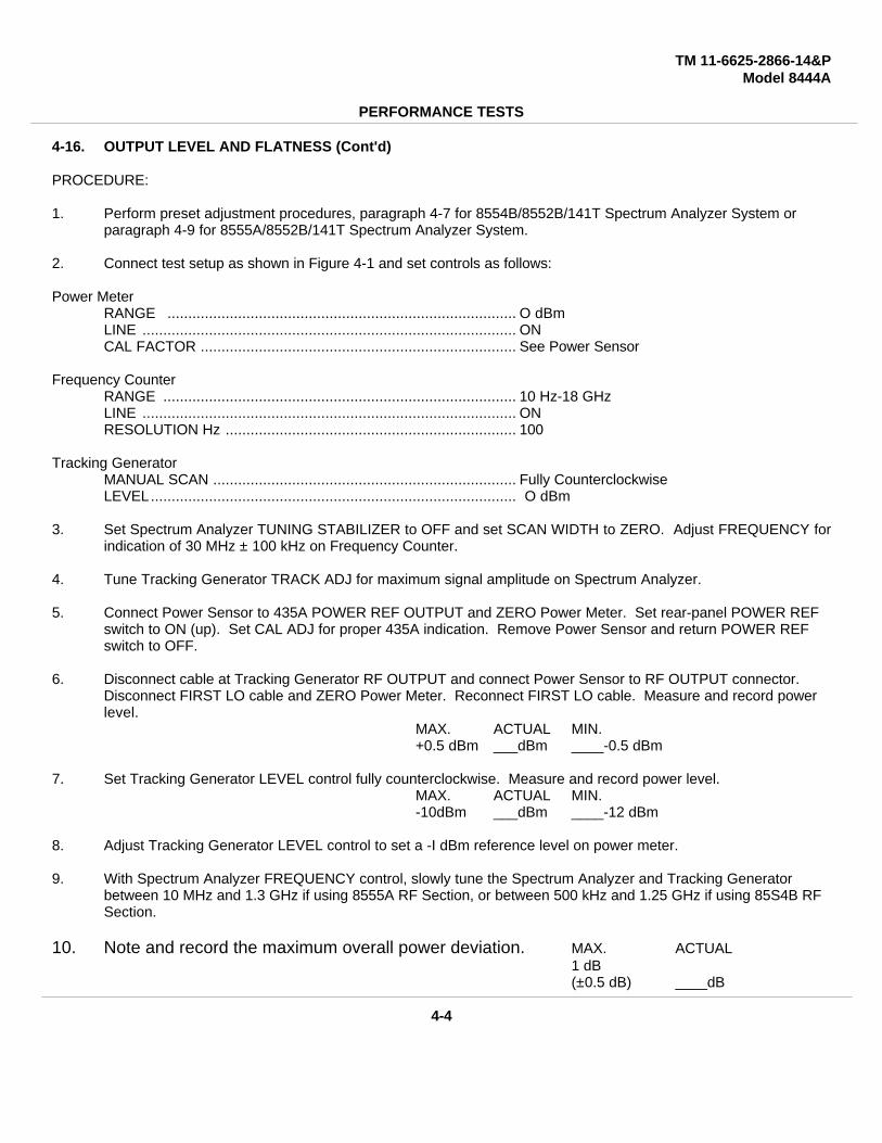
4-16. OUTPUT LEVEL AND FLATNESS (Cont'd)
PROCEDURE:
1. Perform preset adjustment procedures, paragraph 4-7 for 8554B/8552B/141T Spectrum Analyzer System or paragraph 4-9 for 8555A/8552B/141T Spectrum Analyzer System.
2. Connect test setup as shown in Figure 4-1 and set controls as follows:
Power MeterRANGE .................................................................................... O dBmLINE .......................................................................................... ONCAL FACTOR ............................................................................ See Power Sensor
Frequency CounterRANGE ..................................................................................... 10 Hz-18 GHzLINE .......................................................................................... ONRESOLUTION Hz ...................................................................... 100
Tracking GeneratorMANUAL SCAN ......................................................................... Fully CounterclockwiseLEVEL........................................................................................ O dBm
3. Set Spectrum Analyzer TUNING STABILIZER to OFF and set SCAN WIDTH to ZERO. Adjust FREQUENCY forindication of 30 MHz ± 100 kHz on Frequency Counter.
4. Tune Tracking Generator TRACK ADJ for maximum signal amplitude on Spectrum Analyzer.
5. Connect Power Sensor to 435A POWER REF OUTPUT and ZERO Power Meter. Set rear-panel POWER REF switch to ON (up). Set CAL ADJ for proper 435A indication. Remove Power Sensor and return POWER REF switch to OFF.
6. Disconnect cable at Tracking Generator RF OUTPUT and connect Power Sensor to RF OUTPUT connector. Disconnect FIRST LO cable and ZERO Power Meter. Reconnect FIRST LO cable. Measure and record power level.
MAX. ACTUAL MIN.+0.5 dBm ___dBm ____-0.5 dBm
7. Set Tracking Generator LEVEL control fully counterclockwise. Measure and record power level.MAX. ACTUAL MIN.-10dBm ___dBm ____-12 dBm
8. Adjust Tracking Generator LEVEL control to set a -I dBm reference level on power meter.
9. With Spectrum Analyzer FREQUENCY control, slowly tune the Spectrum Analyzer and Tracking Generator between 10 MHz and 1.3 GHz if using 8555A RF Section, or between 500 kHz and 1.25 GHz if using 85S4B RF Section.
10. Note and record the maximum overall power deviation. MAX. ACTUAL1 dB(±0.5 dB) ____dB
4-4
TM 11-6625-2866-14&PModel 8444A Performance Tests
PERFORMANCE TESTS
This space intentionally left blank.
4-17. Frequency Stability
SPECIFICATION: Stability: Residual FM (peak-to-peak):
Tuning Section Stabilized Unstablized8554B/8555A 200 Hz 10 kHz
DESCRIPTION: The stability of the Spectrum Analyzer/Tracking Generator System is checked using a HP141T/8553B/8552B Spectrum Analyzer System which has less than 20 Hz peak-to-peak residual FM. The SpectrumAnalyzer in the system must be within residual FM specification limits. Refer to appropriate RF Section Operating andService Manual. There are no adjustments in the Tracking Generator for residual FM.Refer to paragraph 5-10 if residual FM is excessive.
4-5/4-6
TM 11-6625-2866-14&PModel 8444A Performance Tests
PERFORMANCE TESTS
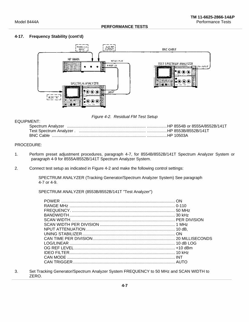
4-17. Frequency Stability (cont'd)
Figure 4-2. Residual FM Test SetupEQUIPMENT:
Spectrum Analyzer ................................................................... .................HP 8554B or 8555A/8552B/141TTest Spectrum Analyzer . ......................................................... .................HP 8553B/8552B/141TBNC Cable ................................................................................ .................HP 10503A
PROCEDURE:
1. Perform preset adjustment procedures, paragraph 4-7, for 8554B/8552B/141T Spectrum Analyzer System orparagraph 4-9 for 8555A/8552B/141T Spectrum Analyzer System.
2. Connect test setup as indicated in Figure 4-2 and make the following control settings:
SPECTRUM ANALYZER (Tracking Generator/Spectrum Analyzer System) See paragraph4-7 or 4-9.
SPECTRUM ANALYZER (8553B/8552B/141T "Test Analyzer")
POWER ................................................................................................. ONRANGE MHz .......................................................................................... 0-110FREQUENCY. ........................................................................................ 50 MHzBANDWIDTH.......................................................................................... 30 kHzSCAN WIDTH. ........................................................................................ PER DIVISIONSCAN WIDTH PER DIVISION ................................................................ 1 MHzNPUT ATTENUATION ............................................................................ 10 dB,UNING STABILIZER............................................................................... ONCAN TIME PER DIVISION...................................................................... 20 MILLISECONDSLOG/LINEAR .......................................................................................... 10 dB LOGOG REF LEVEL...................................................................................... +10 dBmIDEO FILTER.......................................................................................... 10 kHzCAN MODE ............................................................................................ INTCAN TRIGGER....................................................................................... AUTO
3. Set Tracking Generator/Spectrum Analyzer System FREQUENCY to 50 MHz and SCAN WIDTH toZERO.
4-7
TM 11-6625-2866-14&PModel 8444A Performance Tests
PERFORMANCE TESTS
4-17. Frequency Stability (cont'd)
4. Connect Tracking Generator AUX RF OUTPUT to Test Analyzer RF INPUT.
5. Adjust Test Analyzer FREQUENCY control to center signal on CRT Display.
6. Reduce Test Analyzer BANDWIDTH to 1 kHz and SCAN WIDTH PER DIVISION to 2 kHz while keeping signalcentered on CRT display.
7. Set Test Analyzer INPUT ATTENUATION to 30 dB, LOG/LINEAR to LINEAR, and LINEAR SENSITIVITY to20.mV/DIV.
8. Adjust Test Analyzer LINEAR SENSITIVITY Vernier control for a full eight division display.
9. Refer to Figure 4-3. Tune Test Analyzer FINE TUNE so that the upward slope of the display intersects theCENTER FREQUENCY graticule line one division from the top.
NOTE
The linear portion of the analyzer IF filter skirt is used to slope detect low-order residual FM.The analyzer is stabilized, and the detected FM is displayed in the time domain.
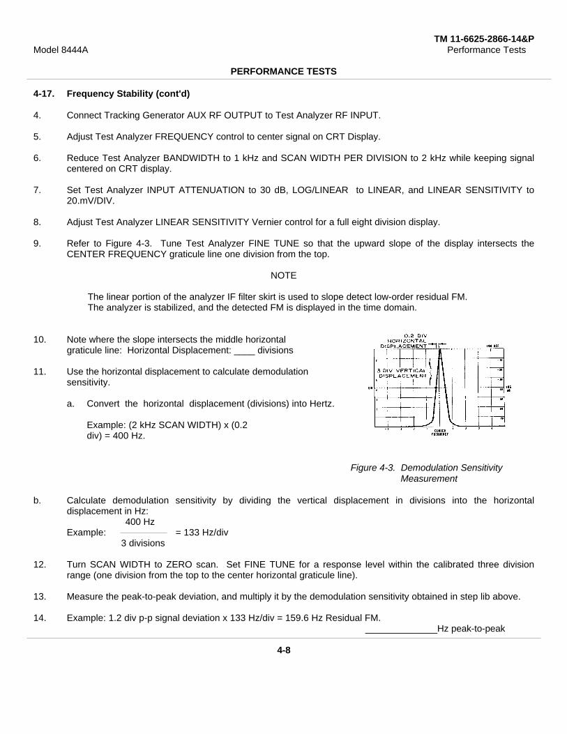
10. Note where the slope intersects the middle horizontalgraticule line: Horizontal Displacement: ____ divisions
11. Use the horizontal displacement to calculate demodulationsensitivity.
a. Convert the horizontal displacement (divisions) into Hertz.
Example: (2 kHz SCAN WIDTH) x (0.2div) = 400 Hz.
Figure 4-3. Demodulation SensitivityMeasurement
b. Calculate demodulation sensitivity by dividing the vertical displacement in divisions into the horizontaldisplacement in Hz:
400 HzExample: = 133 Hz/div
3 divisions
12. Turn SCAN WIDTH to ZERO scan. Set FINE TUNE for a response level within the calibrated three divisionrange (one division from the top to the center horizontal graticule line).
13. Measure the peak-to-peak deviation, and multiply it by the demodulation sensitivity obtained in step lib above.
14. Example: 1.2 div p-p signal deviation x 133 Hz/div = 159.6 Hz Residual FM.______________Hz peak-to-peak
4-8
TM 11-6625-2866-14&PModel 8444A
PERFORMANCE TESTS
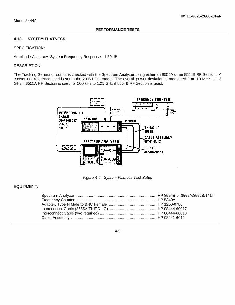
4-18. SYSTEM FLATNESS
SPECIFICATION:
Amplitude Accuracy: System Frequency Response: 1.50 dB.
DESCRIPTION:
The Tracking Generator output is checked with the Spectrum Analyzer using either an 8555A or an 8554B RF Section. Aconvenient reference level is set in the 2 dB LOG mode. The overall power deviation is measured from 10 MHz to 1.3GHz if 8555A RF Section is used, or 500 kHz to 1.25 GHz if 8554B RF Section is used.
Figure 4-4. System Flatness Test Setup
EQUIPMENT:
Spectrum Analyzer ..........................................................................HP 8554B or 8555A/8552B/141TFrequency Counter ..........................................................................HP 5340AAdapter, Type N Male to BNC Female ............................................HP 1250-0780Interconnect Cable (8555A THIRD LO) ...........................................HP 08444-60017Interconnect Cable (two required) ....................................................HP 08444-60018Cable Assembly ..............................................................................HP 08441-6012
4-9

TM 11-6625-2866-14&PModel 8444A
PERFORMANCE TESTS
4-18. SYSTEM FLATNESS (Cont'd)
PROCEDURE:
1. Perform preset adjustment procedures, paragraph 4-7 for 8554B/8552B/141T Spectrum Analyzer System orparagraph 4-9 for 8555A/8552B/141T Spectrum Analyzer System.
2. Connect test setup as shown in Figure 44 and set controls as follows:
Frequency CounterRANGE ...................................................................................................... 10 Hz-18 GHzLINE............................................................................................................. ONRESOLUTION Hz ....................................................................................... 100
Tracking GeneratorMANUAL SCAN .......................................................................................... Fully CounterclockwiseLEVEL ......................................................................................................... 0 dBm
3. Set Spectrum Analyzer SCAN WIDTH to ZERO and adjust FREQUENCY for indication of 30 MHz + 100 kHz onfrequency counter.
4. Set Spectrum Analyzer LOG REF LEVEL to (+)' 10 dBm and LOG/LINEAR to 2 dB LOG.
5. Adjust Tracking Generator TRACK ADJ for maximum signal indication on CRT display.
6. Adjust Spectrum Analyzer LOG REF LEVEL vernier control to position trace on -20 LOG REF graticule line.
7. With Spectrum Analyzer FREQUENCY control, slowly tune the Spectrum Analyzer and Tracking Generatorbetween 10 MHz and 1.3 GHz if using 8555A RF Section, or between 500 kHz and 1.25 GHz if using 8554B RFSection.
8. Note and record the maximum overall power deviation (one minor division on center vertical graticule line equals0.4 dB).
MAX. ACTUAL3 dB(±1.5 dB) ____dB
4-10
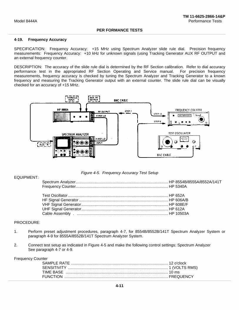
TM 11-6625-2866-14&PModel 8444A Performance Tests
PER FORMANCE TESTS
4-19. Frequency Accuracy
SPECIFICATION: Frequency Accuracy: +15 MHz using Spectrum Analyzer slide rule dial. Precision frequencymeasurements: Frequency Accuracy: +10 kHz for unknown signals (using Tracking Generator AUX RF OUTPUT andan external frequency counter.
DESCRIPTION: The accuracy of the slide rule dial is determined by the RF Section calibration. Refer to dial accuracyperformance test in the appropriated RF Section Operating and Service manual. For precision frequencymeasurements, frequency accuracy is checked by tuning the Spectrum Analyzer and Tracking Generator to a knownfrequency and measuring the Tracking Generator output with an external counter. The slide rule dial can be visuallychecked for an accuracy of +15 MHz.
Figure 4-5. Frequency Accuracy Test SetupEQUIPMENT:
Spectrum Analyzer.................................................................................. HP 8554B/8555A/8552A/141TFrequency Counter.................................................................................. HP 5340A
Test Oscillator......................................................................................... HP 652AHF Signal Generator ............................................................................... HP 606A/BVHF Signal Generator............................................................................. HP 608E/FUHF Signal Generator............................................................................. HP 612ACable Assembly . ................................................................................. HP 10503A
PROCEDURE:
1. Perform preset adjustment procedures, paragraph 4-7, for 8554B/8552B/141T Spectrum Analyzer System orparagraph 4-9 for 8555A/8552B/141T Spectrum Analyzer System.
2. Connect test setup as indicated in Figure 4-5 and make the following control settings: Spectrum AnalyzerSee paragraph 4-7 or 4-9.
Frequency CounterSAMPLE RATE ...................................................................................... 12 o'clockSENSITIVITY ......................................................................................... 1 (VOLTS RMS)TIME BASE ........................................................................................... 10 msFUNCTION ............................................................................................ FREQUENCY
4-11

TM 11-6625-2866-14&PModel 8444A Performance Tests
PERFORMANCE TESTS
4-19. Frequency Accuracy (cont'd)Tracking Generator
TRACK ADJ ........................................................................................ Max signal amplitudeLEVEL ................................................................................................. O dBmMANUAL SCAN .................................................................................. CCW
Test OscillatorFREQUENCY ...................................................................................... 500 kHz (8554B); 10 MHz
(8555A)OUTPUT ATTENUATOR .................................................................... OdBm
3. Allow instruments to warm up and stabilize for at least 2 hours.
4. Set Spectrum Analyze SCAN WIDTH PER DIVISION to 5 MHz, BANDWIDTH to 30 kHz, center FINETUNE control and set FREQUENCY to 0 MHz.
NoteDuring all adjustments of FREQUENCY control approach dial setting in a clockwise direction.
5. Check displacement of LO feed thru signal from CRT CENTER FREQUENCY graticule line.≤ 3 Div
6. Connect Test Oscillator 50o output to Frequency Counter and adjust oscillator frequency for an indication of 500kHz (8554B) or 10 MHz (8555A).
7. Disconnect cable between Tracking Generator RF OUTPUT and Spectrum Analyzer INPUT.
8. Connect Test Oscillator to Spectrum Analyzer INPUT and tune Spectrum Analyzer to Test Oscillator frequency.
9. Reduce Spectrum Analyzer SCAN WIDTH PER DIVISION to 5 kHz and BANDWIDTH to 1 kHz keeping signalcentered on CRT display with FREQUENCY and FINE TUNE controls.
10. Set SCAN WIDTH to ZERO and tune FINE TUNE for maximum signal amplitude.
11. Disconnect Test Oscillator from Spectrum Analyzer and connect Tracking Generator OUTPUT to SpectrumAnalyzer INPUT.
12. Adjust Tracking Generator TRACK ADJ for maximum signal amplitude on CRT display.
13. Connect Tracking Generator AUX RF OUTPUT to Frequency Counter. Measure and record frequency.8554B 500 +10 kHz____________
8555A10MHz+10kHz____________
14. Repeat steps 6 through 13 at selected frequencies using appropriate signal generator in place of test oscillator.
4-12

TM 11-6625-2866-14&PModel 8444A Performance Tests
PERFORMANCE TESTS
4-20. Harmonic Distortion
SPECIFICATION: Harmonic Distortion: 25 dB below output level. Nonharmonic (spurious) signals: >40 dB belowoutput level.
DESCRIPTION: With the Tracking Generator and Spectrum Analyzer operating as a system, the RF OUTPUT from theTracking Generator is observed using a separate spectrum analyzer. The output signal is checked for signal level ofboth harmonic and spurious signals.
Figure 4-6. Harmonic Distortion Test SetupEQUIPMENT:
Spectrum Analyzer .......................................................................HP 8554B or 8555A/8552B/141TTest Spectrum Analyzer . .............................................................HP 8553B/8552B/141TRF Section ....................................................................................HP 8554B or 8555ABNC Cable ....................................................................................HP 10503AAdapter ..........................................................................................UG-201A/U
PROCEDURE:1. Perform preset adjustment procedures, paragraph 4-7, for 8554B/8552/141T Spectrum Analyzer System or
paragraph 4-9 for 8555A/8552/141T Spectrum Analyzer System.
2. Connect test setup as indicated in Figure 4-6 and make the following control settings:
Tracking Generator/Spectrum Analyzer SystemSee paragraph 4-7 or 4-9.
Spectrum Analyzer (8553B/8552B/141T "Test Analyzer")FREQUENCY ................................................................................ 50 MHzBANDWIDTH................................................................................. 300 kHzSCAN WIDTH ...............................................................................PER DIVISIONSCAN WIDTH PER DIVISION ...................................................... 0 MHzINPUT ATTENUATION ................................................................. 20 dBBASE LINE CLIPPER ................................................................... 10 o'clockVIDEO FILTER .............................................................................OFFSCAN TIME PER DIVISION .......................................................... 2 MILLISECONDSLOG/LINEAR ................................................................................ 10 dB LOG
4-13

TM 11-6625-2866-14&PModel 8444A Performance Tests
PERFORMANCE TESTS
4-20. Harmonic Distortion (cont'd)
LOG REF LEVEL ........................................................................................ 0 dBmLOG REF LEVEL Vernier............................................................................. 0SCAN MODE ............................................................................................... INTSCAN TRIGGER . ..................................................................................... LINE
Tracking Generator/Spectrum Analyzer SystemTracking Generator
TRACK ADJ ............................................................................................... Max signal levelLEVEL ......................................................................................................... 0 dBm
Spectrum AnalyzerBAND* ....................................................................................................... n=1 - (2.05 GHz IF)FREQUENCY .............................................................................................. 50 MHzTUNING STABILIZER ................................................................................. OFFSIGNAL IDENTIFIER* . ............................................................................. OFFBANDWIDTH............................................................................................... 300 kHzSCAN WIDTH.............................................................................................. PER DIVISIONSCAN WIDTH PER DIVISION .................................................................... 10 MHzINPUT ATTENUATION ................................................................................ 20 dBBASE LINE CLIPPER .................................................................................. 9 o'clockSCAN TIME PER DIVISION ........................................................................ 0.5 SECONDSLOG/LINEAR ............................................................................................. 10 dB LOGLOG REF LEVEL Vernier ........................................................................... 0VIDEO FILTER ........................................................................................... OFFSCAN MODE .............................................................................................. INTSCAN TRIGGER . ...................................................................................... LINE
*8555A RF Section only
3. Disconnect the cable between Tracking Generator RF OUTPUT and Spectrum Analyzer INPUT.
4. Connect cable between Tracking Generator RF OUTPUT and the INPUT of the "Test Analyzer".
5. Observe the "Test Analyzer" display for harmonic and spurious signals. A typical display is shown in Figure 4-7.The Tracking Generator fundamental signal is shown between the -2 and -1 graticule lines. The secondharmonic is shown between the +1 and +2 lines with the third harmonic shown between the +4 and +5 lines. Theamplitude of the second harmonic is approximately 36 dB below the fundamental. The third harmonic is downapproximately 50 dB. A spurious signal with an amplitude of approximately -58 dBm is shown between the -4and -3 graticule lines.
6. Change the Tracking Generator/Spectrum Analyzer System controls as follows:
Tracking GeneratorLEVEL ......................................................................................................... -10 dBm (CCW)
Spectrum AnalyzerFREQUENCY . .......................................................................................... 250 MHzSCAN WIDTH PER DIVISION ..................................................................... 50 MHzSCAN TIME PER DIVISION......................................................................... 1 SECOND
7. Replace the "Test Analyzer'* RF Section with either an 8554B or 8555A RF Section.
4-14
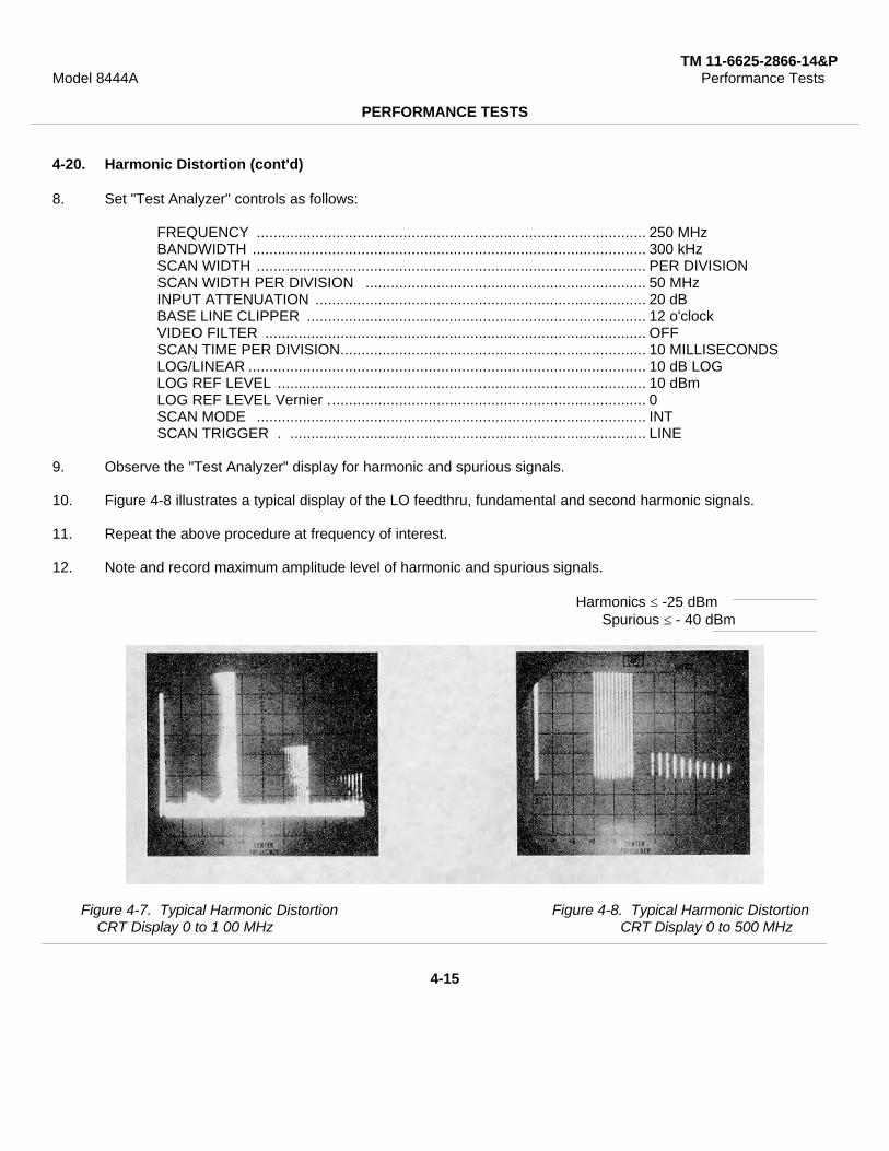
TM 11-6625-2866-14&PModel 8444A Performance Tests
PERFORMANCE TESTS
4-20. Harmonic Distortion (cont'd)
8. Set "Test Analyzer" controls as follows:
FREQUENCY ............................................................................................. 250 MHzBANDWIDTH .............................................................................................. 300 kHzSCAN WIDTH ............................................................................................. PER DIVISIONSCAN WIDTH PER DIVISION ................................................................... 50 MHzINPUT ATTENUATION ............................................................................... 20 dBBASE LINE CLIPPER ................................................................................. 12 o'clockVIDEO FILTER ........................................................................................... OFFSCAN TIME PER DIVISION......................................................................... 10 MILLISECONDSLOG/LINEAR ............................................................................................... 10 dB LOGLOG REF LEVEL ........................................................................................ 10 dBmLOG REF LEVEL Vernier ............................................................................ 0SCAN MODE ............................................................................................. INTSCAN TRIGGER . ..................................................................................... LINE
9. Observe the "Test Analyzer" display for harmonic and spurious signals.
10. Figure 4-8 illustrates a typical display of the LO feedthru, fundamental and second harmonic signals.
11. Repeat the above procedure at frequency of interest.
12. Note and record maximum amplitude level of harmonic and spurious signals.
Harmonics ≤ -25 dBmSpurious ≤ - 40 dBm
Figure 4-7. Typical Harmonic Distortion Figure 4-8. Typical Harmonic DistortionCRT Display 0 to 1 00 MHz CRT Display 0 to 500 MHz
4-15
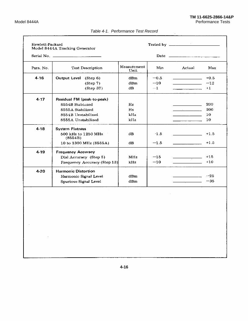
TM 11-6625-2866-14&PModel 8444A Performance Tests
Table 4-1. Performance Test Record
4-16
TM 11-6625-2866-14&PModel 8444A Adjustments
SECTION VADJUSTMENTS
5-1. INTRODUCTION
5-2. This section describes adjustments required toreturn the Tracking Generator to peak operatingcondition after repairs are made. Included in thissection are test setups, and check and adjustmentprocedures. A test card for recording data is included atthe back of this section. Adjustment and test pointlocation illustrations are contained in Figures 8-4 and 8-5.
5-3. The adjustment procedures are arranged innumerical order. For best results, this order should befollowed. Record data, taken during adjustments, in thespaces provided and/or in the data test card at the endof this section. Comparison of initial data with datataken during periodic adjustments assists in preventivemaintenance and troubleshooting.
NoteControl settings are called out for a HP8555A Spectrum Analyzer RF Section.If the RF Section used is a HP 8554Bdisregard BAND and SIGNAL
IDENTIFIER control settings.Otherwise, the Spectrum Analyzercontrol settings apply to eitherinstrument.
5-4. EQUIPMENT REQUIRED
5-5. Each check and adjustment procedure containsa list of test equipment required for that particular test.Table 1-3 contains a tabular list of test equipment andaccessories required. In addition, the table contains therequired minimum specifications and a suggestedmanufacturers model number.
5-6. FACTORY SELECTED COMPONENTS
5-7. Factory selected components are designated byan asterisk (*) on the schematic diagrams in Section VIIIof this manual. Table 8-1 contains a list of factoryselected components by reference designation, basis ofselection, and schematic diagram location on which thecomponent is illustrated.
5-1

TM 11-6625-2866-14&PModel 8444A Adjustments
ADJUSTMENTS
5-8. Power Supply, Check and Adjustment
REFERENCE: Service Sheet 5.
DESCRIPTION: Power supplies in the Tracking Generator provide regulated output of +20 and -10 volts. The +20 voltsupply is adjustable and provides the reference for the -10 volt supply. These checks verify proper operation of thepower supplies.
Figure 5-1. Power Supply Check and Adjustment Test Setup
EQUIPMENT:Digital Voltmeter with 3443A Plug-in ........................................................... HP 3440AAC Voltmeter (Multifunction Voltmeter) ....................................................... HP 410CVariable Voltage Transformer ..................................................................... General Radio W5MT3AAC Voltmeter .............................................................................................. HP 400ECable Assy (terminated with probe and alligator clip) .................................. HP 10501ACable Assy (dual banana plug to probe and alligator clip) ............................ HP 11003A
PROCEDURE:
1. Connect test setup as indicated in Figure 5-1.
2. Remove top cover and right side cover from Tracking Generator.
3. Connect digital voltmeter test leads to AlTP1 and chassis ground.
4. Remove shield from power line module and connect ac voltmeter (HP 410C) across the outside terminals of theACCESSORY OUTLET connector J6. (The outside terminals of J6 are connected by the 98 and 908 color codedwires to the power line module.)
5-2
TM 11-6625-2866-14&PModel 8444A Adjustments
ADJUSTMENTS5. Apply power to the Tracking Generator. Measure and record the +20 volt output. Vary the input ac line voltage
from 103.5 to 126.5 volts. The +20 volt regulated output should not vary more than 20 mV.
AC Input +20 Vdc Output103.5V _____________115V _____________126.5V _____________
6. Set ac line voltage to 115 volts. Adjust AlR14 for +20.00 Vdc +20 mV at test point A1TP1.
7. Disconnect ac voltmeter from connector J6.
8. Connect digital voltmeter to A7C3 and chassis ground (-10 volt test point).
9. Measure and record voltage level. Voltage level should be -10.0 +0.5 volts.-10.0 Vdc Output ______________
10. Set HP 400E AC Voltmeter RANGE to .001 VOLTS full scale and measure ac ripple on +20 and -10 volt senselines. Ripple should be less than 200 pV. Measure and record ac ripple between power supply sense lines andchassis ground.
+20 Volt Output XA1 pin 6________-10 Volt Output A7C3____________
11. Remove input line power and replace cover over power line module.
12. Replace right side cover and top cover.13. If the dc supplies are out of tolerance, refer to Service Sheet 5 for trouble isolation procedure.
5-3

TM 11-6625-2866-14&PModel 8444A Adjustments
ADJUSTMENTS
5-9. 1.55 GHz Oscillator Power Level, Frequency Check and Adjustment
REFERENCE: Service Sheet 3.
DESCRIPTION: The 1.55 GHz local oscillator is checked for power output level and frequency tuning range. Oscillatorfrequency is determined primarily by the LO cavity, with tuning range determined by the drive voltage from the oscillatordriver. The oscillator is checked first for power level and then for frequency and tuning range.
Figure 5-2. 1.55 GHz LO Power Level and Frequency Check and Adjustment Test Setup
EQUIPMENT:Power Meter with HP 8478B Thermistor Mount ............................................ HP 432AFrequency Counter with HP 5254C Plug-in ................................................ HP 5245LDigital Voltmeter with HP 3443A Plug-in ..................................................... HP 3440ATest Leads (dual banana plug to probe and alligator clip) ........................... HP 11003ACable Assy, SMA male to BNC male ........................................................... HP 08555-60076Cable Assy, male BNC connectors .............................................................. HP 10503ACoaxial Attenuator, Option 010 ................................................................... HP 8491AAdapter BNC barrel (HP Part Number 1250-0080) ..................................... UG 914A/UAdapter (BNC to Type N) ............................................................................ UG 201A/U
PROCEDURE:
1. Perform Power Supply Check and Adjustment, paragraph 5-8.
2. Apply power to Tracking Generator and allow 1 hour for instrument to warm up and stabilize.
3. Disconnect Cable W8 at Isolator AT3 J2 (see Figures 8-4 and 8-12).
4. With test setup as indicated in Figure 5-2, connect Power Meter to Isolator AT3 J2 via 08555-60076 cable, .10dB attenuator and UG 914A/U adapter.
5. Rotate TRACK ADJ control throughout its tuning range while noting power level indicated on Power Meter.
6. Minimum power output must be greater than +5 dBm.
>+5 dBm
5-4

TM 11-6625-2866-14&PModel 8444A Adjustments
ADJUSTMENTS
5-9. 1.55 GHz Oscillator Power Level, Frequency Check and Adjustment (cont'd)
7. Connect Frequency Counter to Isolator AT3 J2 via 08555-60076 cable, UG 914A/U adapter and BNC to BNCcable.
8. Rotate TRACK ADJ control fully counterclockwise and record oscillator frequency.
1, 548, 000 ±500 kHz _____9. Rotate TRACK ADJ control fully clockwise and record oscillator frequency
1, 552, 000 +500 kHz ______
10. Record frequency tuning range (frequency recorded in step 9 minus frequency recorded in step 8).
4, 000 ±500 kHz __________
11. If data recorded in steps 8, 9, and 10 is within tolerance no adjustment is required.
12. If data recorded in steps 8, 9, or 10 is not within tolerance proceed with step 13.
13. Connect Digital Voltmeter to test point A2TP5.
14. Set TRACK ADJ control fully clockwise. Set "MAX" TUNE potentiometer A2R26 and "MIN" TUNE potentiometerA2R27 fully counterclockwise. Measure voltage at A2TP5. Voltage should be +1 *0.1 Vdc.
+0.9_________+1.1 Vdc15. Measure and record oscillator frequency.
16. Adjust "MAX" TUNE potentiometer A2R26 to increase oscillator frequency 4, 000 +50 kHz above frequencyrecorded in step 15. Record oscillator frequency.
17. Set TRACK ADJ control to center of tuning range recorded in steps 15 and 16 above. Record oscillatorfrequency.
18. If frequency recorded in step 17 is not within +500 kHz of 1.550 GHz adjust A7ADJ 1 to tune oscillator frequencyto 1.550 GHz±100 kHz.
19. If oscillator frequency is adjusted, repeat steps 15 through 18.
20. Disconnect Power Meter and connect W8 Cable to Isolator AT3 J2.
21. Replace right side panel cover.
5-5

TM 11-6625-2866-14&PModel 8444A Adjustments
ADJUSTMENTS
5-10. 1.55 GHz Oscillator Residual FM Check
REFERENCE: Service Sheet 3.
DESCRIPTION: The 1.55 GHz oscillator is checked for residual FM by mixing the oscillator output with a stable signalsource and observing the resultant output on a calibrated spectrum analyzer display. The second converter in TrackingGenerator is used to mix the oscillator output with the 1500 MHz comb signal from a Frequency Comb Generator. Themixer output is displayed using a HP 141T/8553B/8552B Spectrum Analyzer System which has less than 20 Hz peak-to-peak residual FM. There are no adjustments for oscillator residual FM. Perform power supply check for excessive rippleif residual FM is excessive.
Figure 5-3. 1.55 GHz LO Residual FM Check Test Setup
EQUIPMENT:Spectrum Analyzer System ........................................................................ HP 141T/8553B/8552BFrequency Comb Generator ........................................................................ HP 8406ACable Assy, Selectro male to Selectro female ............................................ HP 11592-60003Cable Assy, Selectro female to BNC male (2 each)...................................... HP 11592-60001Adapter (BNC to Type N) ............................................................................ UG 201A/U
PROCEDURE:1. Perform Power Supply Check and Adjustment, paragraph 5-8.
2. Perform 1.55 GHz Oscillator Power Level, Frequency Check and Adjustment, paragraph 5-9.
3. Apply power to Spectrum Analyzer System, Frequency Comb Generator and Tracking Generator. Allow at leastone (1) hour for equipment stabilization.
4. Disconnect Cable W4 at Mixer Assy A6 and Cable W8 at First Converter A5J2 (see Figures 8-4 and 8-12).Connect 11592-60003 cable between W8 and A6 J1.
5. Disconnect Cable W9 from A6 J2 and connect 11592-60001 cable between A6 J2 and Frequency CombGenerator.
6. Disconnect Cable W10 from A6 J3 and connect 11592-60001 cable between A6 J3 and Spectrum Analyzer RFinput.
7. Set instrument controls as follows:
5-6
TM 11-6625-2866-14&PModel 8444A Adjustments
ADJUSTMENTS
5-10. 1.55 GHz Oscillator Residual FM Check (cont'd)
Tracking GeneratorLINE OFF/ON .............................................................................................. .ONTRACK ADJ................................................................................................. Centered
Frequency Comb GeneratorCOMB FREQUENCY - MHz ....................................................................... 100 MHzOUTPUT AMPLITUDE ............................................................................... Maximum (CW)
Spectrum AnalyzerPOWER ...................................................................................................... ONRANGE MHz ............................................................................................... 0-110FREQUENCY ............................................................................................. 50 MHzBANDWIDTH . .......................................................................................... 30 kHzSCAN WIDTH ............................................................................................. PER DIVISIONSCAN WIDTH PER DIVISION ................................................................... 1 MHzINPUT ATTENUATION ................................................................................ 0 dBTUNING STABILIZER.................................................................................. ONSCAN TIME PER DIVISION ....................................................................... 20 MILLISECONDSLOG/LINEAR .............................................................................................. 10 dB LOGLOG REF LEVEL ........................................................................................ +10 dBmVIDEO FILTER . ........................................................................................ 10 kHzSCAN MODE ............................................................................................. INTSCAN TRIGGER . ..................................................................................... AUTO
8. Rotate Tracking Generator TRACK ADJ control while observing CRT display.
NOTEWith the 1.55 GHz oscillator tuned to 1550 MHz both the 1500 and 1600 MHz comb signals willproduce a response at 50 MHz.
9. Adjust the TRACK ADJ control until the responses are separated by 2 MHz (2 divisions) on the display.
10. Adjust Spectrum Analzyer FREQUENCY control to center largest response on CRT display.
11. Reduce BANDWIDTH to 1 kHz and SCAN WIDTH PER DIVISION to 2 kHz while keeping signal centered onCRT display.
12. Switch Spectrum Analyzer LOG/LINEAR to LINEAR and adjust sensitivity controls for a full eight division display.
13. Refer to Figure 5-4. Tune FINE TUNE so that the upward slope of the display intersects the CENTERFREQUENCY graticule line one division from the top.
NOTEThe linear portion of the analyzer IF filter skirt is used to slope detect low-order residual FM. Theanalyzer is stabilized, and the detected FM is displayed in the time domain.
5-7

TM 11-6625-2866-14&PModel 8444A Adjustments
ADJUSTMENTS
5-10. 1.55 GHz Oscillator Residual FM Check (cont'd)
14. Note where the slope intersects the middle horizontalgraticule line: Horizontal Displacement: ___________divisions
15. Use the horizontal displacement to calculate demodulationsensitivity.
a. Convert the horizontal displacement(divisions) into Hertz.
Example: (2 kHz SCAN WIDTH) x (0.2div) = 400 Hz.
b. Calculate demodulation sensitivity by dividing the verticaldisplacement in divisions into the horizontal displacement in Hz:
400 H z/di Figure 5-4. Demodulation SensitivityExample: = 133 Hz/div Measurement
3 divisions
16. Turn SCAN WIDTH to ZERO scan. Set FINE TUNE for a response level within the calibrated three divisionrange (one division from the top to the center horizontal graticule line).
17. Measure the peak-to-peak deviation, and multiply it by the demodulation sensitivity obtained in step 15b above.
Example: 0.5 div p-p signal deviation x 133 Hz/div = 66.5 Residual FM.
Hz peak-to-peak
18. Install cables removed in steps 4 through 6.
5-8

TM 11-6625-2866-14&PModel 8444A Adjustments
ADJUSTMENTS
5-11. First Converter Check and Adjustment
REFERENCE: Service Sheet 3.
DESCRIPTION: The 1.55 GHz oscillator cavity and the two 2.05 GHz IF bandpass cavities in the first converter areadjusted for maximum output signal level. A 8555A Spectrum Analyzer System (8555A/ 8552/140) should be usedduring the adjustment procedure. In addition to providing the third LO input signal the output signal can be displayedduring the adjustment. With the analyzer operating in the linear mode, the cavities are alternately adjusted for maximumindication on the CRT. When only the 8554L Spectrum Analyzer System is available, the output can be monitored usinga power meter such as the HP 432B.
Figure 5-5. First Converter Check and Adjustment Test SetupEQUIPMENT:
Spectrum Analyzer....................................................................................... HP 8555A/8552/141TCable Assembly ......................................................................................... HP 11592-60001Adapter ....................................................................................................... UG 201A/UWrench ........................................................................................................ 5/16 inchAllen Driver ................................................................................................. No.10
PROCEDURE:1. Perform 1.55 GHz Oscillator Power Level, Frequency Check and Adjustment, paragraph 5-9.
2. With test setup as indicated in Figure 5-5, set controls as follows:
Tracking GeneratorLINE ............................................................................................................ ONTRACK ADJ ................................................................................................ CenteredLEVEL ......................................................................................................... 0 dBm
Spectrum AnalyzerBAND........................................................................................................... n=1 - (2.05 GHz IF)FREQUENCY .............................................................................................. 500 MHzBANDWIDTH . .......................................................................................... 100 kHzSCAN WIDTH PER DIVISION .................................................................... 5 MHzINPUT ATTENUATION .............................................................................. 20 dBSCAN TIME PER DIVISION ....................................................................... 20 MILLISECONDSLOG REF LEVEL ........................................................................................ (+) 10 dBmLOG/LINEAR .............................................................................................. 10 dB LOG
5-9
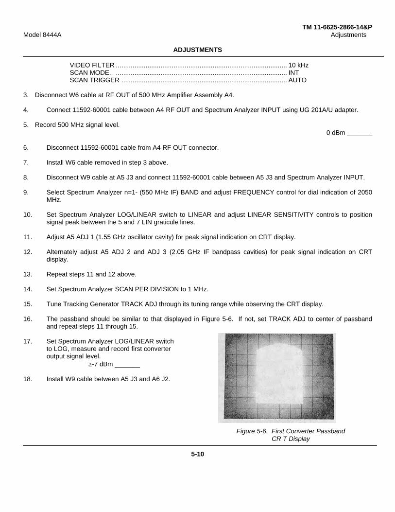
TM 11-6625-2866-14&PModel 8444A Adjustments
ADJUSTMENTS
VIDEO FILTER ............................................................................................ 10 kHzSCAN MODE. ............................................................................................ INTSCAN TRIGGER ......................................................................................... AUTO
3. Disconnect W6 cable at RF OUT of 500 MHz Amplifier Assembly A4.
4. Connect 11592-60001 cable between A4 RF OUT and Spectrum Analyzer INPUT using UG 201A/U adapter.
5. Record 500 MHz signal level.≅0 dBm _______
6. Disconnect 11592-60001 cable from A4 RF OUT connector.
7. Install W6 cable removed in step 3 above.
8. Disconnect W9 cable at A5 J3 and connect 11592-60001 cable between A5 J3 and Spectrum Analyzer INPUT.
9. Select Spectrum Analyzer n=1- (550 MHz IF) BAND and adjust FREQUENCY control for dial indication of 2050MHz.
10. Set Spectrum Analyzer LOG/LINEAR switch to LINEAR and adjust LINEAR SENSITIVITY controls to positionsignal peak between the 5 and 7 LIN graticule lines.
11. Adjust A5 ADJ 1 (1.55 GHz oscillator cavity) for peak signal indication on CRT display.
12. Alternately adjust A5 ADJ 2 and ADJ 3 (2.05 GHz IF bandpass cavities) for peak signal indication on CRTdisplay.
13. Repeat steps 11 and 12 above.
14. Set Spectrum Analyzer SCAN PER DIVISION to 1 MHz.
15. Tune Tracking Generator TRACK ADJ through its tuning range while observing the CRT display.
16. The passband should be similar to that displayed in Figure 5-6. If not, set TRACK ADJ to center of passbandand repeat steps 11 through 15.
17. Set Spectrum Analyzer LOG/LINEAR switchto LOG, measure and record first converteroutput signal level.
≥-7 dBm _______
18. Install W9 cable between A5 J3 and A6 J2.
Figure 5-6. First Converter PassbandCR T Display
5-10
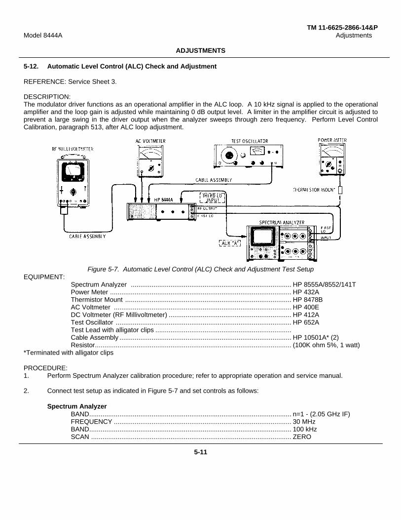
TM 11-6625-2866-14&PModel 8444A Adjustments
ADJUSTMENTS
5-12. Automatic Level Control (ALC) Check and Adjustment
REFERENCE: Service Sheet 3.
DESCRIPTION:The modulator driver functions as an operational amplifier in the ALC loop. A 10 kHz signal is applied to the operationalamplifier and the loop gain is adjusted while maintaining 0 dB output level. A limiter in the amplifier circuit is adjusted toprevent a large swing in the driver output when the analyzer sweeps through zero frequency. Perform Level ControlCalibration, paragraph 513, after ALC loop adjustment.
Figure 5-7. Automatic Level Control (ALC) Check and Adjustment Test SetupEQUIPMENT:
Spectrum Analyzer ..................................................................................... HP 8555A/8552/141TPower Meter ................................................................................................ HP 432AThermistor Mount ........................................................................................ HP 8478BAC Voltmeter .............................................................................................. HP 400EDC Voltmeter (RF Millivoltmeter) ................................................................. HP 412ATest Oscillator ............................................................................................. HP 652ATest Lead with alligator clips ........................................................................Cable Assembly ........................................................................................... HP 10501A* (2)Resistor........................................................................................................ (100K ohm 5%, 1 watt)
*Terminated with alligator clips
PROCEDURE:1. Perform Spectrum Analyzer calibration procedure; refer to appropriate operation and service manual.
2. Connect test setup as indicated in Figure 5-7 and set controls as follows:
Spectrum AnalyzerBAND........................................................................................................... n=1 - (2.05 GHz IF)FREQUENCY .............................................................................................. 30 MHzBAND........................................................................................................... 100 kHzSCAN .......................................................................................................... ZERO
5-11

TM 11-6625-2866-14&PModel 8444A Adjustments
ADJUSTMENTS
5-12. Automatic Level Control (ALC) Check and Adjustment (cont'd)INPUT ATTENUATION ........................................................................ 10 dBTUNING STABLIZER .......................................................................... ONSIGNAL IDENTIFIER........................................................................... OFFBASE LINE CLIPPER ......................................................................... Max CCWSCAN TIME PER DIVISION ................................................................ 10 MILLISECONDSLOG REF LEVEL ................................................................................ +10 dBmLOG/LINEAR ...................................................................................... LOGVIDEO FILTER ................................................................................... OFFSCAN MODE ..................................................................................... INTSCAN TRIGGER . ............................................................................. AUTO
Tracking GeneratorLINE .................................................................................................... ONTRACK ADJ ....................................................................................... Peak signal indication on CRTLEVEL ............................................................................................... 0 dBm
3. Allow instruments to warm up and stabilize for at least 30 minutes.
4. Adjust TRACK ADJ for maximum signal indication on CRT display.
5. Disconnect cable between Tracking Generator RF OUTPUT and Spectrum Analyzer INPUT.
6. Connect Thermistor Mount and Power Meter to Tracking Generator RF OUTPUT.
7. Connect test lead jumper between A2TP1 and A2TP2.
8. Adjust A2R17 "NULL ADJ" for output level of 0 1.0 dBm indication on Power Meter.
9. Remove jumper between A2TP1 and A2TP2.
10. Adjust A2R41 "O dBm LEVEL" for output level of 0 +0.5 dBm indication on Power Meter.
11. Adjust Test Oscillator for 10 kHz output.
12. Connect Test Oscillator output through 100K ohm resistor to A2TP4.
13. Connect AC Voltmeter to A2TP1.
14. Adjust Test Oscillator output amplitude for an indication of -7 dB (.001 VOLTS RANGE) on AC Voltmeter.
15. Connect AC Voltmeter to A2TP2.
16. Adjust A2R7 "GAIN ADJ" for an indication of -10 dB (.001 VOLTS RANGE) on AC Voltmeter.
17. Adjust A2R17 "NULL ADJ" for Tracking Generator output of 0 dBm.
18. Repeat steps 16 and 17 until both levels are obtained.
19. Disconnect AC Voltmeter and Test Oscillator.
20. Repeat steps 7 through 10 above.
21. Connect DC Voltmeter across A2TP1 and A2TP3, COM to A2TP1 and VOLTS to A2TP3.5-12
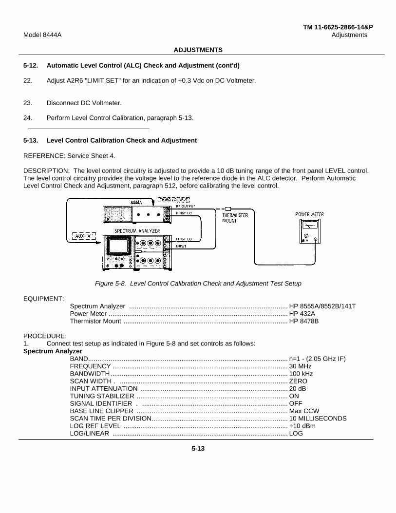
TM 11-6625-2866-14&PModel 8444A Adjustments
ADJUSTMENTS
5-12. Automatic Level Control (ALC) Check and Adjustment (cont'd)
22. Adjust A2R6 "LIMIT SET" for an indication of +0.3 Vdc on DC Voltmeter.
23. Disconnect DC Voltmeter.
24. Perform Level Control Calibration, paragraph 5-13.
5-13. Level Control Calibration Check and Adjustment
REFERENCE: Service Sheet 4.
DESCRIPTION: The level control circuitry is adjusted to provide a 10 dB tuning range of the front panel LEVEL control.The level control circuitry provides the voltage level to the reference diode in the ALC detector. Perform AutomaticLevel Control Check and Adjustment, paragraph 512, before calibrating the level control.
Figure 5-8. Level Control Calibration Check and Adjustment Test Setup
EQUIPMENT:Spectrum Analyzer ..................................................................................... HP 8555A/8552B/141TPower Meter ................................................................................................ HP 432AThermistor Mount ........................................................................................ HP 8478B
PROCEDURE:1. Connect test setup as indicated in Figure 5-8 and set controls as follows:Spectrum Analyzer
BAND........................................................................................................... n=1 - (2.05 GHz IF)FREQUENCY .............................................................................................. 30 MHzBANDWIDTH............................................................................................... 100 kHzSCAN WIDTH . .......................................................................................... ZEROINPUT ATTENUATION ............................................................................... 20 dBTUNING STABILIZER ................................................................................. ONSIGNAL IDENTIFIER . .............................................................................. OFFBASE LINE CLIPPER ................................................................................. Max CCWSCAN TIME PER DIVISION......................................................................... 10 MILLISECONDSLOG REF LEVEL ........................................................................................ +10 dBmLOG/LINEAR .............................................................................................. LOG
5-13
TM 11-6625-2866-14&PModel 8444A Adjustments
ADJUSTMENTS
5-13. Level Control Calibration Check and Adjustment (cont'd)VIDEO FILTER ................................................................................... OFFSCAN MODE ...................................................................................... INTSCAN TRIGGER.................................................................................. AUTO
Tracking GeneratorLINE..................................................................................................... ONTRACK ADJ......................................................................................... Peak signal indication on CRTLEVEL ................................................................................................. OdBm
2. Adjust TRACK ADJ for maximum signal indication on CRT display.
3. Disconnect cable between Tracking Generator RF OUTPUT and Spectrum Analyzer INPUT.
4. Connect Thermistor Mount and Power Meter to Tracking Generator RF OUTPUT.
5. Adjust A2R41 "O dBm LEVEL" for an indication of 0 ±0.5 dBm on Power Meter.
6. Set Tracking Generator LEVEL control fully counterclockwise.
7. Adjust A2R40 "'-10 dBm LEVEL" for an indication of -10 to -12 dBm on Power Meter.
8. Set Tracking Generator LEVEL control to 0 dBm.
9. Repeat steps 5 through 7 until Power Meter indicates 0 dBm with LEVEL control fully clockwise.
10. Disconnect Power Meter and Thermistor Mount from Tracking Generator RF OUTPUT.
11. Connect cable between Tracking Generator RF OUTPUT and Spectrum Analyzer INPUT.
12. Set Tracking Generator TRACK ADJ for maximum signal level on Spectrum Analyzer CRT display.
13. Note and record signal level at 30 MHz. 0 +0.5 dBm
5-14
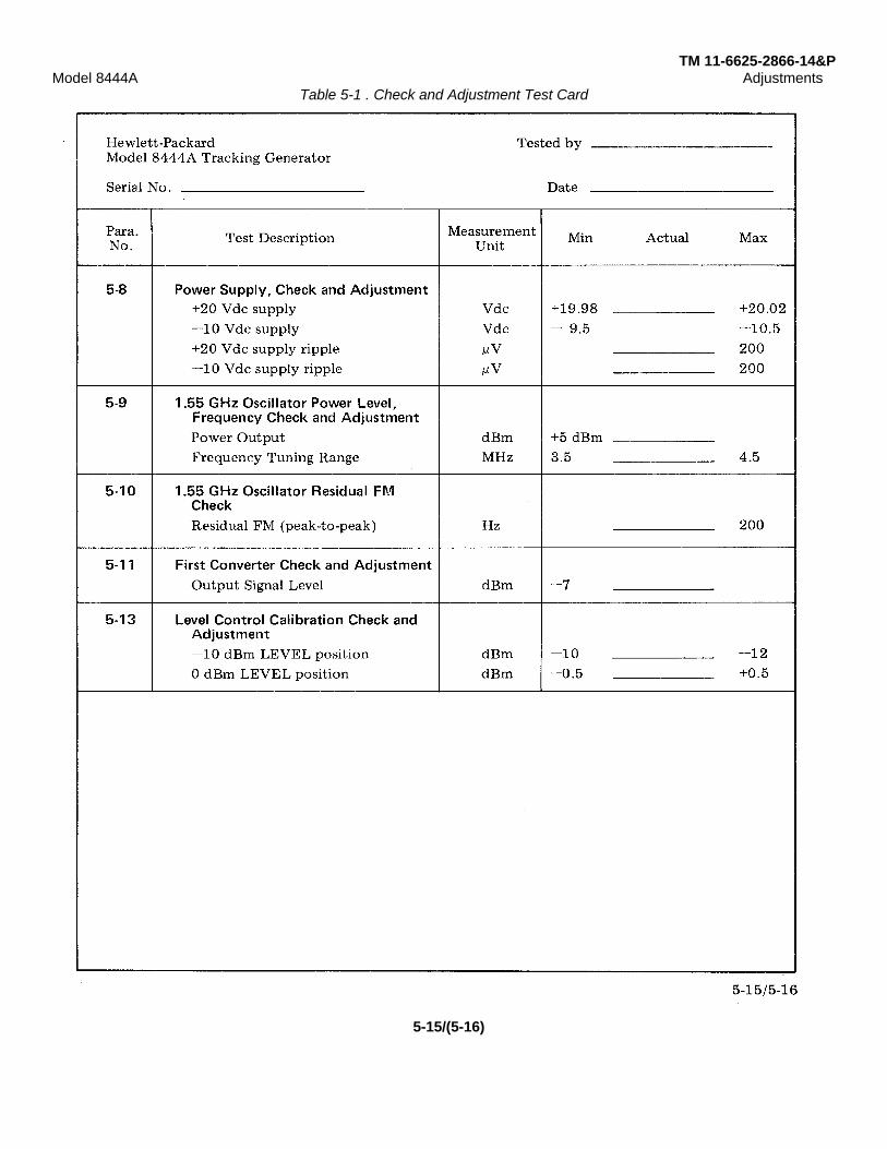
TM 11-6625-2866-14&PModel 8444A Adjustments
Table 5-1 . Check and Adjustment Test Card
5-15/(5-16)
TM 11-6625-2866-14&PModel 8444A Replaceable Parts
SECTION VIREPLACEABLE PARTS
6-1. INTRODUCTION
6-2. This section contains information for orderingparts. Table 6-1 lists abbreviations used in the parts listand throughout the manual. Table 6-2 lists allreplaceable parts in reference designator order. Table6-3 contains names and addresses that correspond tothe manufacturer's code numbers.
6-3. ABBREVIATIONS
6-4. Table 6-1 gives a list of abbreviations used inthe parts list, schematics, and throughout the manual.In some cases, two forms of the abbreviations aregiven:one is in capital letters, while the other is partial or nocapitals. This occurs because in the parts list,abbreviations are all capitalized. However, in theschematics and other parts of the manual, otherabbreviation forms are used with both lower case andupper case letters.
6-5. REPLACEABLE PARTS LIST
6-6. Table 6-2 is a list of replaceable parts and isorganized as follows:
a. Electrical assemblies and their componentsin alpha-numerical order by reference designation.
b. Chassis-mounted parts in alpha-numericorder by reference designation.
c. Miscellaneous parts.
The information given for each part consists of thefollowing:
a. The Hewlett-Packard part number.
b. The total quantity (Qty) used in theinstrument.
c. The description of the part.
d. The typical manufacturer of the part in a five-digit code.
e. Manufacturer code number for the part.
The total quantity for each part is given only once - atthe first appearance of the part number in the list.
6-7. ORDERING INFORMATION
6-8. To order a part listed in the replaceable partstable, note the Hewlett-Packard part number and thenCross-Reference that part number to the National StockNumber listed in table 6-5. Then order through normalordering channel 1 s.
6-9. If the part number does not have a NationalStock Number, then order through normal orderingchannels using the Hewlett-Packard part number.
6-10. Refer to table 6-4 for part number to NSN cross-reference.
6-1
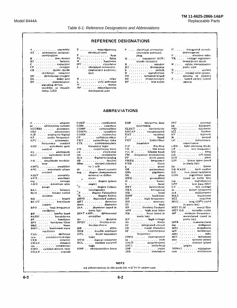
TM 11-6625-2866-14&PModel 8444A Replaceable Parts
Table 6-1. Reference Designations and Abbreviations
6-2

TM 11 -6625-2866-14&PModel 8444A Replaceable Parts
Table 6-1. Reference Designations and Abbreviations (Cont’d)
6-3

TM 11 -6625-2866-14&PModel 8444A Replaceable Parts
Table 6-2. Replaceable Parts
Reference HP Part Number Qty Description Mfr Mfr Part NumberDesignation Code
A1 08444-60001 1 BOARD ASSY:POWER SUPPLY 28480 08444-60001A1C1 0160-3460 2 C:FXD CER 0.05 UF +80-20Z 100VDCW 56289 C023El06 L503LS22-CDMA1C2 0180-0116 4 C:FXD ELECT 6.8 UF 10 35VDCW 56289 1500685X903582-DYSA1C3 0160-2199 2 C:FXO M1CA 30 PF 5% 300VDCW 28480 0160-2199A1C4 0180-0228 3 C:FXD ELECT 22 UF 105 15VDCW 56289 150D0226X9015B2-DYS
A1C5 0180-0116 C:FXD ELECT 6.8 UF 10% 35VDCW 56289 1500685X903582-DYSA1C6 0160-3460 C:FXD CER 0.05 UF +80-203 100VDCW 56289 C023El101OL503ZS22-CDMA1C7 0160-2199 C:FXD 11CA 30 PF 5% 300VDCW 28480 0160-2199A1C8 0180-0228 C:FXD ELECT 22 UF 10 15VDCW 56289 1500226X901582-DYSA1C9 0180-0116 C:FXD ELECT 6.8 UF 10% 35VDCW 56289 1500685X903582-DYS
A1CR1 1901-0159 8 DIODE:SILICON 0.75A 400PIV 04713 SR1358-4A1CR2 1901-0159 DIODE:SILICON 0.75A 400PIV 04713 SR1358-4A1CR3 1901-0159 DIODE:SILICON 0.75A 400PIV 04713 SR1358-4A1CR4 1901-0159 DIODE:SILICON 0.75A 400PIV 04713 SR1358-4A1CR5 1901-0040 5 DIODE:SILICON 30MA 30WV 07263 FDG1088
A1CR6 1901-0200 2 DIODE:SILICON 100 PIV 3A 02735 1N4998A1CR7 1901-0200 DIODE:SILICON 100 PIV 3A 02735 1N4998A1CR8 1902-3182 1 DIODE BREAKDOWN:SILICON 12.1V 5% 28480 1902-3182A1CR9 1902-3256 1 DIODE:BREAKOOWN SILICON 23.78 5% 28480 1902-3256A1CR10 1884-0012 1 RECTIFIER:SILICON CONTROLLED 2N3528 02735 2N3528
A1CR11 1902-0761 1 DIODE:BREAKDOWN 5.9 TO 6.5V 12954 1N821A1CR12 1901-0159 DIODE:SILICON 0.75A 400PIV 04713 SR1358-4A1CR13 1901-0156 DIODE:SILICON 0.75A 400IV 04713 SR1358-4A1CR13 1901-0159 DIODE:SILICON 0.75A 400PIV 04713 SR1358-4A1CR14 1901-0159 D1ODE:SILICON 0.75A 400PIV 04713 SR1358-4A1CR15 1901-0159 DIODE:SILICON 0.75A 400PIV 04713 SR1358-4
AiCR16 1901-0040 DIODE:SILICON 30MA 30WV 07263 FDG1088A1F1 2110-0012 2 FUSE:0.5 AMP 250V 75915 312.500A1F2 2110-0012 FUSE:0.5 AMP 250V 75915 312.500A1MP1 2110-0269 4 CL1P:FUSE 0.250" DIA 91506 6008-32CNA1MP2 2110-0269 CL1P:FUSE 0.250” DIA 91506 6008-32CN
A1MP3 2110-0269 CLIP:FUSE 0.250" D1A 91506 6008-32CNA1MP4 2110-0269 CLIP:FUSE 0.250" D1A 91506 6008-32CNA1Q1 1853-0020 7 TSTR:SI PNP[SELECTED FROM 2N37021 28480 1853-0020A1Q2 1853-0012 2 TSTR:SI PNP 80131 2N2904AA1Q3 1854-0039 2 TSTR:SI NPN 80131 2N3053
A1Q4 1854-0071 3 TSTR:SI NPN(SELECTED FROM 2N3704) 28480 1854-0071A1Q5 1853-0020 TSTR:SI PNP(SELECTED FROM 2N3702) 28480 1853-0020A1Q6 1854-0039 TSTR:SI NPN 80131 2N3053A1Q7 1854-0071 TSTR:SI NPN(SELECTED FROM 2N3704) 28480 1854-0071A1R1 0698-3160 2 R:FXD MET FLM 31.6K OHM 1% 1/8W 28480 0698-3160
A1R2 0698-3445 2 R:FXD MET FLM 348 OHM 1X 1/8W 28480 0698-3445A1R3 0757-0440 4 R:FXD MET FLM 7.50K OHM 1t 1/8W 28480 0757-0440A1R4 0811-1666 2 R:FXD MWW 1.0 OHM 5% 2W 28480 0811-1666A1R5 0698-3441 4 R:FXD MET FLM 215 OHM 12 1/8W 28490 0698-3441A1R6 0157-0440 R:FXD MET FLM 7.50K OHM 1% 1/8W 28480 0757-0440
A1R7 0757-0280 5 R:FXD MET FLM 1K OHM 1% 1/8W 28480 0757-0280A1R8 0757-0401 3 R:FXD MET FLM 100 OHM 1% 1/8W 28480 0757-04011AR9 0757-0438 3 R:FXD MET FLM 5.11K OHM 1% 1/8W 28480 0757-0438A1R10 0683-0275 2 R:FXD COMP 2.7 OHM 52 1/4W 01121 CB 27G5A1R11 0757-0280 R:FXD MET FLM LK OHM 1% 1/8W 28480 0757-0280
ALR12 0757-0278 1 R:FXD MET FLM 1.78K OHM 1% 1/8W 28480 0757-0278A1R13 0757-0289 1 R:FXD MET FLM 13.3K OHM 3 1/81W 28480 0757-0289A1R14 2100-1758 3 R:VAR WW 1K OHM 53 TYPE V 1W 28480 2100-1758A1R15 0757-0200 1 R:FXO MET FLM 5.62K OHM 1% 1/8W 28480 0757-0200A1RL16 0811-1666 R:FXD WW 1.0 OHM 5% 2W 28480 0811-1666
A1R17 0698-3441 R:FXD MET FLM 215 OHM 1% 1/8W 28480 0698-3441A1R18 0757-0440 R:FXD MET FLM 7.50K OHM 1% 1/8W 28480 0757-04401AR19 0757-0280 R:FXD MET FLM 1K OHM 1% 1/8W 28480 0757-0280A1R20 0757-0440 R:FXD MET FLM 7.50K OHM 1% 1/8W 28480 0757-0440A1R21 0698-0084 3 R:FXD MET ELM 2.15K OHM 1% 1/8W 28480 0698-0084
A1R23 0698-0084 R:FXD MET FLM 2.15K OHM 1% 1/8W 28480 0698-0084A1R22 0698-0084 R:FXD MET FLM 2.15K OHM 1% 1/8W 28480 0698-0084A1R24 0683-0275 R:FXD COMP 2.7 OHM 5% 1/4W 01121 CB 27G5A1TB1 08444-20001 1 BOARD:BLANK PC 28480 08444-20001A1TP1 0360-1514 12 TERMINAL PIN:SQUARE 28480 0360-1514
A1TP2 0360-1514 TERMINAL PIN:SQUARE 28480 0360-1514A1TP3 0360-1514 TERMINAL PIN:SQUARE 28480 0360-1514A1TP4 0360-1514 TERMINAL PIN:SOUARE 28480 0360-1514A1TP5 0360-1514 TERMINAL PIN:SQUARE 28480 0360-1514A1LT6 0360-1514 TERMINAL PIN:SQUARE 28480 0360-1514
A1U1 1820-0223 3 INTEGRATED CIRCUIT:OPERATIONAL AMPL. 28480 1820-0223A1U2 1820-0223 INTEGRATED CIRCUIT:OPERATIONAL AMPL. 28480 1820-0223A2 08444-60002 1 BOARD ASSY:DRIVER 28480 08444-60002A2C1 0180-0116 C:FXO ELECT 6.8 UF 10% 35VDCW 56289 150D685X903582-DYSA2C2 0180-2205 1 C:FXD ELECT 0.33 UF 10% 35VDCW 56289 1500334X9035A2-DYS
6-4
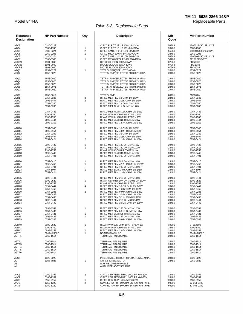
TM 11 -6625-2866-14&PModel 8444A Replaceable Parts
Table 6-2. Replaceable Parts
Reference HP Part Number Qty Description Mfr Mfr Part NumberDesignation Code
A2C3 0180-0228 C:FXD ELECT 22 UF 10% 15VDCW 56289 1500226X901582-DYSA2C4 0180-1746 1 C:FXD ELECT 15 UF 10% 20VDCW 28480 0180-1746A2C5 0180-0374 2 C:FXD TANT. 10 UF 10% 20VDCW 56289 1500106X902082-DYSA2C6 0160-2208 1 C:FXD MICA 330 PF 5% 300VDCW 28480 0160-2208A2C7 0180-0374 C:FXD TANT. 10 UF 10% 20VDCW 56289 1500106X902082-DYSA2C8 0160-0300 1 C:FXD MY 0.0027 UF 10% 200VDCW 56289 292P27292-PTSA2CR1 1901-0040 DIODE:SILICON 30HA 30WV 07263 FDG1088A2CR2 1901-0040 DIOOE:SILICON 30MA 30WV 07263 FDG1088A2CR3 1901-0040 DIODE:SILICON 30MA 30WV 07263 FDG1088A2Q1 1854-0221 1 TSTR:SI NPN(REPL.BY 2N4044} 28480 1854-0221A2Q2 1853-0020 TSTR:SI PNP(SELECTED FROM 2N3702) 28480 1853-0020
A2Q3 1853-0020 TSTR:SI PNP(SELECTED FROM 2N3702) 28480 1853-0020A2Q4 1853-0020 TSTR:SI PNP(SELECTED FROM 2N3702) 28480 1853-0020A2Q5 1853-0020 TSTR:SI PNP(SELECTED FROM 2N3702) 28480 1853-0020A2Q6 1854-0071 TSTR:SI NPN(SELECTED FROM 2N3704) 28480 1854-0071A2Q7 1853-0020 TSTR:SI PNP(SELECTED FROM 2N3702) 28480 1853-0020
A2Q8 1853-0012 TSTR:SI PNP 80131 2N2904AA2R1 0757-0346 3 R:FXD MET FLM 10 OHM 1% 1/8W 28480 0757-0346A2R2 0698-3454 2 R:FXD MET FLM 215K OHM 1% 1/8W 28480 0698-3454A2R3 0757-0280 R:FXD MET FLM 1K OHM 1% 1/8W 28480 0757-0280A2R4 0757-0280 R:FXO MET FLM 1K OHM 1% 1/8W 28480 0757-0280
A2R5 0757-0438 R:FXO MET FLM 5.11K OHM 1% 1/8W 28480 0757-0438A2R6 2100-1760 3 R:VAR WW 5K OHM 5% TYPE V 1W 28480 2100-1760A2R7 2100-1760 R:VAR WW 5K OHM 5% TYPE V 1W 28480 2100-1760A2R8 0698-3444 1 R:FXD MET ELM 316 OHM 1% 1/8W 28480 0698-3444A2R9 0698-3156 1 R:FXD MET FLM 14.7K OHM 1% 1/8W 28480 0698-3156
A2R10 0757-0346 R:FXD MET FLM 10 OHM 1% 1/8W 28480 0757-0346A2R11 0698-3154 1 R:FXD MET FLM 4.22K OHM 1% I/8W 28480 0698-3154A2R12 0757-0346 R:FXD MET FLM 10 OHM 1% 1/8W 28480 0757-0346A2R13 0698-3454 R:FXD MET FLM 215K OHM 1% 1/8W 28480 0698-3454A2R14 0757-0424 2 R:FXD MET FLM 1.10K OHM 1% 1/8W 28480 0757-0424
A2R15 0698-3437 1 R:FXD MET FLM 133 OHM 1% 18W 28480 0698-3437A2R16 0757-0817 1 R:FXD MET FLM 750 OHM 1% 1/2W 28480 0757-0817A2R17 2100-1758 R:VAR WW IK OHH 5t TYPE V 1W 28480 2100-1758A2R18 0698-3445 R:FXD MET ELM 348 OHM 1% 18W 28480 0698-3445A2R19 0757-0401 R:FXD MET FLM 100 OHM 1% 1/8W 28480 0757-0401
A2R20 0757-0416 1 R:FXD MET FLM 511 OHM 1% 1/8W 28480 0757-0416A2R21 0698-3450 1 R:FXD MET FLM 42.2K OHM 1% 1/18W 28480 0698-3450A2R22 0757-0401 R:FXD MET FLM 100 OHM 1% 1/8W 28480 0757-0401A2R23 0757-1094 1 R:FXD MET ELM 1.47K OHM 1% 1/8W 28480 0757-1094A2R24 0757-0424 R:FXD MET FLM 1.10K OHM 1% 1/8W 28480 0757-0424
A2R25 0698-3441 R:FXD MET FLM 215 OHM 1% 1/8W 28480 0698-3441A2R26 2100-2522 1 R:VAR CERMET 10K OHM 10% LIN 1/2W 28480 2100-2522A2R27 2100-1758 R:VAR WW 1K OHM 5% TYPE V 1W 28480 2100-1758A2R28 0757-0442 4 R:FXD MET FLM 10.OK OHM 1% 1/8W 28480 0757-0442A2R29 0757-0465 R:FXD MET FLM 100K OHM 1% 1/8W 28480 0757-0465A2R30 0757-0288 2 R:FXD MET FLM 9.09K OHM 1% 1/8W 28480 0757-0288A2R31 0757-0442 R:FXD MET FLM 10.0K OHM 1% 1/8W 28480 0757-0442A2R32 0757-0438 R:FXD MET FLM 5.11K OHM I% 1/8W 28480 0757-0438A2R33 0698-3441 R:FXD MET FLM 215 OHM i1%1/8W 28480 0698-3441A2R34 0757-0442 R:FXD MET FLM 10.OK OHM 1% 1/8W 28480 0757-0442
A2R35 0698-3399 1 R:FXD MET FLM 133 OHM 1% 1/2W 28480 0698-3399A2R36 0757-0439 R:FXD MET FLM 6.81K OHM 1% 1/8W 28480 0757-0439A2R37 0757-0421 1 R:FXD MET ELM 825 OHM 1% 1/8W 28480 0757-0421A2838 0698-3438 1 R:FXD MET FLM 147 OHM 1% 1/8W 28480 0698-3438A2R39 0757-0288 R:FXD MET FLM 9.09K OHM 1% 1/8W 28480 0757-0288
A2R40 2100-2522 1 R:VAR WW 10K OHM 10% TYPE V 1W 19701 ET50X103A2R41 2100-1760 R:VAR WW 5K OHM 5% TYPE V 1W 28480 2100-1760A2R42 0698-3151 1 R:FXD MET FLM 2.87K OHM 1% 1/8W 28480 0698-3151A2TB1 08444-20002 1 BOARD:BLANK PC 28480 08444-20002A2TP1 0360-1514 TERMINAL PIN:SQUARE 28480 0360-1514
A2TP2 0360-1514 TERMINAL PIN:SQUARE 28480 0360-1514A2TP3 0360-1514 TERMINAL PIN:SQUARE 28480 0360-1514A2TP4 0360-1514 TERMINAL PIN:SQUARE 28480 0360-1514A2TP5 0360-1514 TERMINAL PIN:SQUARE 28480 0360-1514A2TP6 0360-1514 TERMINAL PIN:SQUARE 28480 0360-1514
A2UI 1820-0223 INTEGRATED CIRCUIT:OPERATIONAL AMPL. 28480 1820-0223A3 5086-7025 1 AMPLIFIER DETECTOR 28480 0960-2038A3 NOT FIELD REPAIRABLEA4 AMPLIFIER ASSY:500 MHZ
A4C1 0160-2357 2 C:FXD CER FEED-THRU 1000 PF +80-20% 28480 0160-2357A4C2 0160-2357 C:FXD CER FEED-THRU 1000 PF +80-20% 28480 0160-2357A4C3 0160-2152 1 C:FXD CER 10 PF 20% 500VDCW 28480 0160-2152A4J1 1250-1220 2 CONNECTOR:RF 50 OHM SCREW-ON TYPE 98291 50-051-0109A4J2 1250-1220 CONNECTOR:RF 50 OHM SCREW-ON TYPE 98291 50-051-0109
6-5

TM 11 -6625-2866-14&PModel 8444A Replaceable Parts
Table 6-2. Replaceable Parts
Reference HP Part Number Qty Description Mfr Mfr Part NumberDesignation Code
A4MP1 08444-00006 1 COVER:500 MHZ AMPLIFIER 28480 08444-00006A4MH2 08444-20011 1 HOUSING:500 MHZ AMPLIFIER 28480 08444-20011A4A1 08444-60005 1 BOARD ASSY:500 MHZ AMPLIFIER 28480 08444-60005A4A1C1 0160-2266 11 C:FXD CER 24 PF 5% 500VDCW 72982 301-000-COGO-240JA4A1C2 0160-3456 C:FXD CER 1000 PF 10% 250 VDCW 28480 0160-3456
A4A1C3 0160-2266 C:FXD CER 24 PF 5% 500VDCW 72982 301-000-COGO-240JA4A1C4 0160-2266 C:FXD CER 24 PF 5t 500VDCW 72982 301-000-COGO-240JA4A1C5 0160-2266 C:FXD CER 24 PF 5% 500VDCW 72982 301-000-COGO-240JA4A1C6 0160-2266 C:FXD CER 24 PF 5% 500VDCW 72982 301-000-COGO-240JA4A1C7 0160-2266 C:FXO CER 24 PF 5% 500VDCW 72982 301-000-COGO-240J
A4A1C8 0160-2266 C:FXD CER 24 PF 500VDCW 72982 301-000-COGO-240JA4A1C9 0160-2266 C:FXD CER 24 PF 500VDCW 72982 301-000-COGO-240JA4A1C10 0160-2266 C:FXD CER 24 PF 500VDCW 72982 301-000-COGO-240JA4A1C11 0160-2266 C:FXD CER 24 PF 500VDCW 72982 301-000-CG000-240JA4A1CR1 1901-0639 2 DIOOE:PIN 1MHZ TO 1GHZ 28480 1901-0639
A4A1CR2 1901-0639 DIODE:PIN 1MHZ TO 1GHZ 28480 1901-0639A4A1L1 9100-2252 4 COIL/CHOKE 0.27 UH 10% 28480 9100-2252A441L2 9100-2252 COIL/CHOKE 0.27 UH 10% 28480 9100-2252A4A1L3 9100-2252 COIL/CHOKE 0.27 UH 10% 28480 9100-2252A4A1L4 9100-2252 COIL/CHOKE 0.27 UH 10% 28480 9100-2252
A4A1Q1 1854-0345 3 TSTR:SI NPN 80131 2N5179A4A1Q2 1854-0345 TSTR:SI NPN 80131 2N5179A4A1Q3 1854-0345 TSTR:SI NPN 80131 2N5179A4A1R1 0698-7197 1 R:FXD FLM 23.7 OHM 2% 1/8W 28480 0698-7197A4A1R2 0698-7236 9 R:FXD FLM 1K OHM 2% 1/8W 28480 0698-7236
A4A1R3 0698-7236 R:FXD FLM 1K OHM 2% 1/8W 28480 0698-7236A4A1R4 0698-7236 R:FXD FLM IK OHM 2% 1/8W 28480 0698-7236A4A1R5 0698-7236 R:FXD FLM 1K OHM 2% 1/8W 28480 0698-7236A4A1R6 0698-7236 R:FXD FLM 1K OHM 2% 1/8W 28480 0698-7236A4A1R7 0698-7236 R:FXD FLM 1K OHM 2% 1/8W 28480 0698-7236
A4A1R8 0698-7236 R:FXD FLM 1K OHM 2% 1/8W 28480 0698-7236A4A1R9 0698-7236 R:FXD FLM 1K OHM 2% 1/8W 28480 0698-7236A4A1R10 0698-7236 R:FXD FLM 1K OHM 22 1/8W 28480 0698-7236A4A1R11 0693-7214 1 R:FXD FLM 121 OHM 2% 1/8W 28480 0698-7214A4A1TB1 08444-20005 1 BOARD:BLANK PC 28480 08444-20005
A5 08444-60011 1 CONVERTER ASSY:FIRST 28480 08444-60011A5J1 1250-0829 5 CONNECTOR:RF 50-OHM SCREW ON TYPE 98291 50-045-4610A5J2 1250-0829 CONNECTOR:KF 50-OHM SCREW ON TYPE 98291 50-045-4610A5J3 1250-0829 CONNECTOR:RF 50-OHM SCREW ON TYPE 98291 50-045-4610A5MP1 08555-00033 2 INPUT-OUTPUT LOOP 28480 08555-00033
A5MP2 0516-0005 2 SCREW:PAN HD SLOT DR 0-80 X 0.188" LG 00000 080A5MP3 2200-0111 14 SCREW:PAN HD POLI DR 4-40 X 0.500" LG 00000 OBDA5MP4 08555-20035 1 CAVITY BLOCK:SECOND CONVERTER 28480 08555-20035A5MP5 08444-20012 1 COVER:FIRST CONVERTER 28480 08444-20012A5MP6 2200-0172 2 SCREW:FLAT HD POZI DR 4-40 X 0.875" LG 00000 OBD
A5MP7 08444-20007 1 CENTER-POST 28480 08444-20007A5MP8 2740-0001 3 NUT:HEX 10-32 THREAD 00000 O8DA5MP9 3030-0151 4 SCREW:SOCKET CAP 4-40 THREAD 28480 3030-0151A5MP10 3030-0397 3 SCREW:SET 10-32 UNF-2A THREAD 00000 OBDA5A1 08444-60012 1 MIXER ASSY:FIRST 28480 08444-60012
A5A1C1 0160-2327 1 C:FXO CER 1000 PF 20% 100VDCW 96733 B104BX102MA5A1C2 0160-3861 1 C FXD 18 PF + -5% 250 VDCW 72982 2930-000-3903A5A1C3 0160-3860 1 C:FXD MICA 39 PF 5% 250VDCW 72982 2930-000-390JA5A1CR1 1901-0633 1 DIODE:HOT CARRIER 28480 1901-0633A5A1J1 1250-0829 CONNECTOR:RF 50-OHM SCREW ON TYPE 98291 50-045-4610
A5A1L1 9100-2254 1 COIL/CHOKE .39 UH 10% 28480 9100-2254A5A1MP1 0520-0128 4 SCREW:PAN HD POZI DR 2-56 X 0.250" LG 00000 OBDA5A1MP2 1251-1556 1 CONNECTOR:SINGLE CONTACT 00779 2-330808-8A5A1MP3 08555-00031 1 LID:RESONATOR HOUSING 28480 08555-00031A5A5MP4 085'5-20036 1 RESONATOR HOUSING 28480 08555-20016
A5A1R1 0698-7233 1 R:FXD FLM 750 OHM 2% 1/8W 28480 0698-7233A6 08444-60004 1 MIXER ASSY:OUTPUT 28480 08444-60004A6 NOT RECOMMENDEOD FOR FIELD REPAIRA7 08444-60019 1 OSCILLATOR ASSY:1.55 GHZA7 · NOT RECOMMENDED FOR FIELD REPAIR 28480 08444-60019
A7CI 0163-3827* 1 C:FXD PRC 1 PF 500VDCW 84411 663UW22354W2A7C2 0160-0345 2 C:FXD CEP FEED-THRU 1000 PF 500VDCW 01121 FB2B-102WA7C3 0160-0345 C:FXD CER FEED-THRU 1000 PP 500VDCW 01121 FB28-102WA7C4 0160-2437 1 C FXD CER 5000 PF +80 -20%A7CR1 0122-0245 2 C:VOLTAGE VAR. 6.8 PF 10% 60VDCW 04713 1N5139A7J1 1250-0829 CONNECTOR:KF 5-OHM SCREW ON TYPE 98291 50-045-4610A7L1 1460-0103 1 SPRING:COMPRESSION 0.120" OD 00000 O8DA7Q1 1854-0292 1 TSTR:SI NPN 28480 1854-0292A7R1 0698-7230 1 R:FXD FLM 562 OHM 2% 1/8'W 28480 0698-7230A7R2 0757-0418 1 R:FXD MET FLM 619 OHM 1% 1/8W 28480 0757-0418A8 5060- 1189 POWER LINE MODULE. NON-FILTERED 28480 5060-1189
6-6

TM 11 -6625-2866-14&PModel 8444A Replaceable Parts
Table 6-2. Replaceable Parts
Reference HP Part Number Qty Description Mfr Mfr Part NumberDesignation Code
CHASSIS PARTSAT1 0960-0084 2 ISOLATOR:2-PORT 2-4 GHZ 28480 0960-0084AT2 0960-0084 ISOLATOR:2-PORT 2-4 GHZ 28480 0960-0084AT3 0960-0168 1 ISOLATOR:2-PORT 1.54-1.56 GHZ 28480 0960-0168AT4 11593A 1 TERMINATION:50 OHM 28480 11593AC1 0180-2181 2 C:FXD ELECT 1300 UF +75-10% 50VDCW 56289 3601320050AA2A-DQ8
C1 1210-0013 2 BRACKET:MOUNTING FOR 1-3/8 OD 56289 4586-87AC2 0180-2181 C:FXD ELECT 1300 UF +75-10% 50VDCW 56289 3601320050A02A-DQBC2 1210-0013 BRACKET:MOUNTING FOR 1-3/8 OD 56289 4586-87AC3 0160-0155 1 C:FXD MY 0.0033 UF 10% 200VDCW 28080 0160-0155CP1 1250-0838 1 CONNECTOR:RF ADAPTER TEE 98291 50-085-0000F1 2110-0202 1 FUSE:0.50A 250V SLOW-BLOW 75915 313.500SF1 (FOR 115V OPERATION)F1 2110-02011 FUSE:0.25A 250V SLO-BLO 71400 MDL-1/4FL1 (FOR 230V OPERATION)FL1 0960-0167 1 FILTER:TUBULAR BANDPASS 2.0-3.4 GHZ 28480 0960-0167
J1MPI 1250-0914 1 BODY:RF CONNECTOR 02660 131-150J1MP2 1250-0915 1 CONTACT:RF CONNECTOR 02660 131-149J1MP3 5040-0306 1 INSULATOR 28480 5040-0306J1M4 08555-20093 1 CONTACT:JACK 28480 08555-20093J1MP5 08555-20094 1 BODY:BULKHEAD 28480 08555-20094
J1MP6 2190-0444 1 WASHER:LOCK 00000 O8DJ1MP7 2950-0132 1 NUT:HEX 7/16-28 00000 O8DJ1MP8 08761-2027 1 INSULATOR 28480 08761-2027J4 1250-0118 1 CONNECTOR:BNC 24931 28JR 128-1
J6 1251-2996 1 CONNECTOR:AC POWER 28480 1251-2996Q1 1854-0063 2 TSTR:SI NPN 80131 2N3055Q1 1200-0043 2 INSULATOR:TSTR MOUNTING(TO-3) 71785 293011Q2 1854-0063 TSTR:SI NPN 80131 2N3055Q2 1200-0043 INSULATOR:TSTR MOUNTING(TO-3) 71785 293011
R1 2100-2730 1 R:VAR CERMET 5000 OHM 20% LIN 2W 28480 2100-2730R1 0370-0133 3 KNOB:SKIRTED FOR 0.250" DIA SHAFT 28480 0370-0133R2 2100-2886 1 R:VAR WW 5K OHM 5% LIN 2W 28480 2100-2886R2 0370-0133 KNOB:SKIRTED FOR 0.250" DIA SHAFT 28480 0370-0133R3 2100-2728 1 R:VAR CERNET 1K OHM 20% LIN 2W 28480 2100-2728R3 0370-0133 KNOB:SKIRTED FOR 0.250" DIA SHAFT 28480 0370-0133R4 0698-3449 1 R:FXD MET FLM 28.7K OHM 1% 1/8W 28480 0698-3449R5 0757-3438 1 R FXD MET FLM 5.11 OHM 1% 1/8W 28080 0757-0438S1 3101-1248 1 SWITCH:PUSHBUTTON SPDT ILLUMINATED 87034 53-55480-121/A1HS1DS1 2140-0244 1 LAMP:GLOW MINIATURE 95V 87034 A1HW1 08444-20018 1 CABLE ASSY:FIRST LO INPUT 28480 08444-20018W2 08444-20024 2 CABLE ASSY:FILTER 28480 08444-20024
W3 08444-20024 CABLE ASSY:FILTER 28480 08444-20024W4 08444-20020 1 CABLE ASSY:MIXER ISOLATOR 28480 08444-20020W5 08444-60015 1 CABLE ASSY:THIRD LO INPUT 28480 08444-60015W6 08444-60014 1 CABLE ASSY:FIRST CONVERTER 28480 08444-60014w7 08444-20017 1 CABLE ASSY:OSCILLATOR 28480 08444-20017
W8 08444-20026 1 CABLE ASSY:FIRST ISOLATOR 28480 08444-20026W9 09444-20027 1 CABLE ASSY:FIRST C OUTPUT 28480 08444-20027W10 08444-20021 1 CABLE ASS¥:MIXER-CIRCUIT 28480 08444-20021W11 08444-20019 1 CABLE ASSY:RF OUTPUT(AUXILIARY) 28480 0844O 20019W12 08444-20023 1 CABLE ASSY:RF OUTPUT 28480 08444-20023
W13 08444-60016 1 CABLE ASSY:THIRD LO INPUT 28480 08444-60016W14 08444-60018 3 CABLE ASSY:RF INTERCONNECT 28480 08444-60018W15 0R444-60018 CABLE ASSY:RF INTERCONNECT 28480 08444-60018W16 08444-60018 CABLE ASSY:RF INTERCONNECT 28480 08444-60018W17 08444-60017 1 CABLE ASSY:INTERCONNECTING 28480 08444-60017W18 8120-1348 1 CABLE:LINE POWER 28480 8120-1348XA1 1251-0159 1 CONNECTOR:PC EDGE 2 X 15 CONTACT 71785 251-15-30-261XA2 1251-0135 1 CONNECTOR:PC EDGE 15 CONTACT 95354 91-6915-1500-00XFI 1400-0011 2 CLIP:FUSE 75915 #125002XF1 1400-0011 CLIP:FUSE 75915 #125002XQ1 1200-0041 2 SOCKET:TRANSISTOR 71785 133-32-10-013
XQ2 1200-0041 SOCKET:TRANSISTOR 71785 133-32-10-01308444-60013 1 WIRING HARNESS 28480 08444-60013
T1 9100-3308 1 TRANSFORMER: POWER 115-230 VAC 28480 9100-330848-440 HZ
6-7

TM 11 -6625-2866-14&PModel 8444A Replaceable Parts
Table 6-2. Replaceable Parts
Reference HP Part Number Qty Description Mfr Mfr Part NumberDesignation Code
MECHANICAL PARTSMP1 1490-0030 1 STAND:TILT 28480 1490-0030-MP2 5000-0050 2 TRIM:SIDES 28480 5000-0050MP3 5000-0730 2 COVER:SIDE 3 X 16( BLUE GRAY) 28480 5000-0730MP3 5000-8593 2 COVER:SIDE 3 X 16(OLIVE GRAY) 28480 5000-8593MP4 5020-0900 1 TRIM:PANEL( LIGHT GRAY) 28480 5020-0900MP4 5020-6850 1 TRIM:PANEL( MINT GRAY) 28480 5020-6850MP5 5020-0901 1 TRIM:PANEL( LIGHT GRAY) 28480 5020-0901MP5 5020-6851 1 TRIM:PANEL(MINT GRAY) 28480 5020-6851MP6 5040-0170 4 GUIDE:PLUG-IN PC BOARD 28480 5040-0170
MP7 50b0-0730 2 FRAME ASSY:3 X 16 28480 5060-0730MP8 5060-0740 1 COVER AS5Y:TOP 16L(BLUE GRAY) 28480 5060-0740MP8 5060-8589 I COVER ASSY:TOP 16L(OLIVE GRAY) 28480 5060-8589MP9 5060-0752 1 COVER ASSY:BOTTOM 16L(BLUE GRAY) 28480 5060-0752MP9 5060-8713 1 COVER:BOTTOM 28480 5060-8713
MP10 5060-0767 5 FOOT ASSY:FM 28480 5060-0767MP11 5060-0774 1 RACK MOUNTING KIT:3H (LIGHT GRAY) 28480 5060-0774MP11 5060-8739 1 KIT:RACK MOUNT 3H (MINT GRAY) 28480 5060-8739MP12 08443-40002 1 TRIM STRIP(LIGHT GRAY) 28480 08443-40002MP12 08443-40005 1 TRIM STRIP(MINT GRAY) 28480 08443-40005MP13 08444-00001 1 PANEL:FRONT(BLACK/LIGHT GRAY) 28480 08444-00001MP13 08444-00013 1 PANEL:FRONT(OLIVE BLACK/MINT GRAY) 28480 08444-00013MP14 08444-00002 1 PLATE:CONNECTOR 28480 08444-00002MP14 08444-00015 1 PLATE:CONNECTOR(OLIVE BLACK) 28480 08444-00015MP15 09444-00003 1 DECK:MAIN 28480 08444-00003MP16 08444-00004 I PANEL:REAR 28480 08444-00004
MP17 09444-00007 1 GUARD 28480 08444-00007MP18 08445-00008 4 CLAMP:FRONT PANEL TRIM 28480 08445-00008
Table 6-3. Code List of Manufacturers
MFR ZIPNO. MANUFACTURER NAME ADDRESS CODE
00000 U.S.A. COMMON ANY SUPLIER OF U.S.A.00779 AMP INC.(AIRCRAFT MARINE PROD.) HARRISBURG, PA. 1710101121 ALLEN BRADLEY CO. MILWAUKEE, WIS. 5320403553 AMPHENOL CORP. BRDADVIEW, ILL. 6015302735 RCA SOLID STATE & RECEIVING TUBE DIV. SOMERVILLE, N.J. 0887604713 MOTOROLA SEMICONDUCTOR PROD. INC. PHOENIX, ARIZ. 8500807203 FAIRCHILD CAMEPA & INST. CORP. SEMICONDUCTOR DIV. MOUNTAIN VIEW, CALIF. 9404012954 DICKSON ELECTRONIC CORP. SCOTTSDALE, ARIZ. 8525224931 SPECIALTY CONNECTOR CO. INC. INDIANAPOLIS, IND. 4622728480 HEWLETT-PACKARD COMPANY PALO ALTO, CALIF. 9430456289 SPRAGUE ELECTRIC CO. N. ADAMS, MASS. 0124771400 BUSSMANN MFG. DIV. MC GRAW-EDISON CO. ST. LOUIS, MO. 6301771785 CINCH MFG. CO. DIV TRW INC. ELK GROVE VILLAGE, ILL.72982 ERIE TECHNOLOGICAL PROD. INC. ERIE, PA. 1651275915 LITTELFUSE INC. DES PLAINES, ILL. 6001680131 ELECTRONIC INDUSTRIES ASSOCIATION WASHINGTON D.C. 2000687034 MARCOAK INDUSTRIES ANAHEIM, CALIF. 9280391506 AUGAT INC. ATTLEBORO, MASS. 0270395354 METHODE MFG. CO. ROLLING MEADOWS, ILL. 6000896733 SAN FERNANDO ELECT. MFG. CO. SAN FERNANDO, CALIF. 9134198291 SEALECTRO CORP. MAMAPONECK, N.Y. 0544
6-8
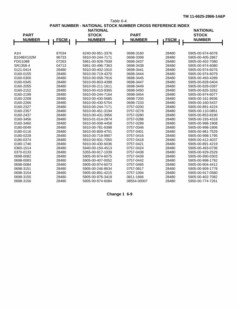
TM 11-6625-2866-14&PTable 6-4.
PART NUMBER - NATIONAL STOCK NUMBER CROSS REFERENCE INDEXNATIONAL NATIONAL
PART STOCK PART STOCKNUMBER FSCM NUMBER NUMBER FSCM NUMBER
A1H 87034 6240-00-951-3376 0698-3160 28480 5905-00-974-6078B104BX102M 96733 5910-00-244-7171 0698-3399 28480 5905-00-405-2867FDG1088 07263 5961-00-928-7939 0698-3437 28480 5905-00-402-7080SR1358-4 04713 5961-00-496-7363 0698-3438 28480 5905-00-974-60800121-0414 28480 5910-00-402-1910 0698-3441 28480 5905-00-974-60760160-0155 28480 5910-00-719-4370 0698-3444 28480 5905-00-974-60790160-0300 28480 5910-00-058-7916 0698-3445 28480 5905-00-493-42890160-0345 28480 5910-00-803-4398 0698-3447 28480 5905-00-828-04040160-2055 28480 5910-00-211-1611 0698-3449 28480 5905-00-828-03970160-2152 28480 5910-00-410-9365 0698-3450 28480 5905-00-826-32620160-2199 28480 5910-00-244-7164 0698-3454 28480 5905-00-974-60770160-2208 28480 5910-00-430-5685 0698-7200 28480 5905-00-161-89360160-2266 28480 5910-00-430-5754 0698-7233 28480 5905-00-160-54370160-2327 28480 5910-00-244-7171 0757-0200 28480 5905-00-891-42240160-2357 28480 5910-00-451-3194 0757-0278 28480 5905-00-110-08510160-2437 28480 5910-00-431-3956 0757-0280 28480 5905-00-853-81900160-3456 28480 5910-01-014-2874 0757-0288 28480 5905-00-193-43180160-3460 28480 5910-00-008-4458 0757-0289 28480 5905-00-998-19080180-0049 28480 5910-00-781-9398 0757-0346 28480 5905-00-998-19060180-0116 28480 5910-00-809-4701 0757-0401 28480 5905-00-981-75290180-0228 28480 5910-00-719-9907 0757-0416 28480 5905-00-998-17950180-0374 28480 5910-00-931-7050 0757-0418 28480 5905-00-412-40370180-1746 28480 5910-00-430-6036 0757-0421 28480 5905-00-891-42190360-1514 28480 5940-00-150-4513 0757-0424 28480 5905-00-493-07360370-0133 28480 5355-00-917-1039 0757-0438 28480 5905-00-929-25290698-0082 28480 5905-00-974-6075 0757-0439 28480 5905-00-990-03030698-0083 28480 5905-00-407-0052 0757-0442 28480 5905-00-998-17920698-0084 28480 5905-00-974-6073 0757-0465 28480 5905-00-904-44120698-3151 28480 5905-00-246-8634 0757-0817 28480 5905-00-909-17780698-3154 28480 5905-00-891-4215 0757-1094 28480 5905-00-917-05800698-3155 28480 5905-00-976-3418 0811-1666 28480 5905-00-402-70820698-3156 28480 5905-00-974-6084 08554-00007 28480 5950-00-774-7261
Change 1 6-9
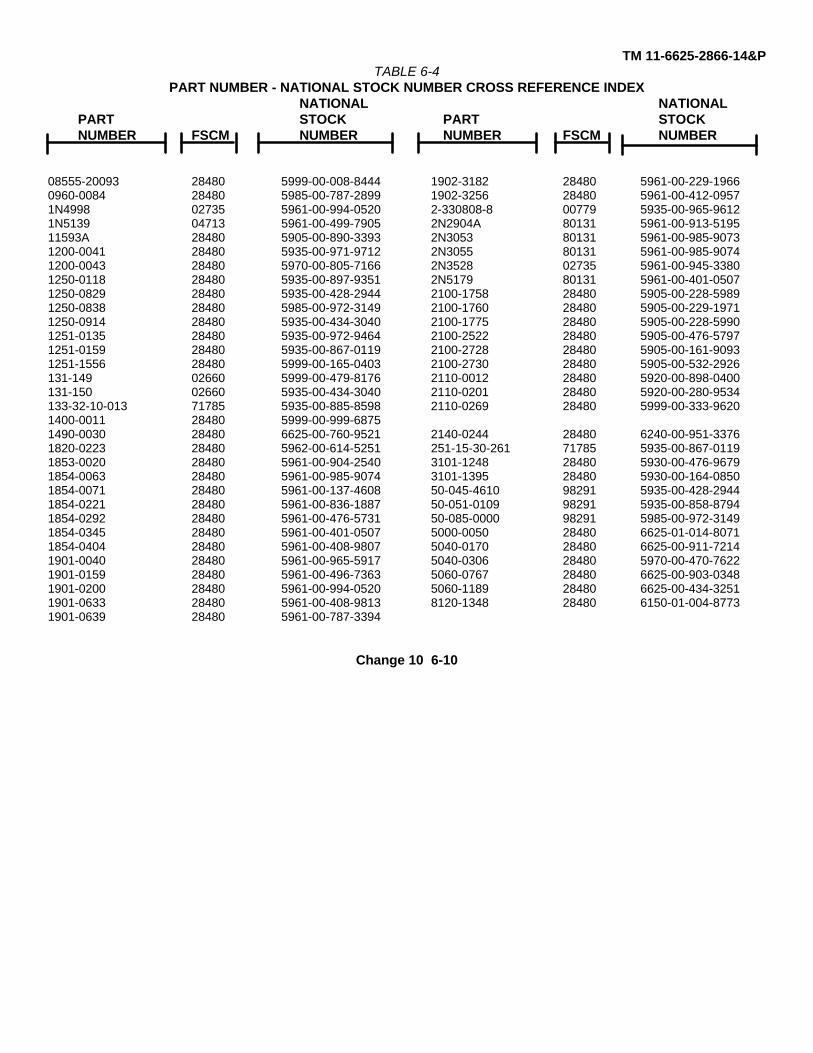
TM 11-6625-2866-14&PTABLE 6-4
PART NUMBER - NATIONAL STOCK NUMBER CROSS REFERENCE INDEXNATIONAL NATIONAL
PART STOCK PART STOCKNUMBER FSCM NUMBER NUMBER FSCM NUMBER
08555-20093 28480 5999-00-008-8444 1902-3182 28480 5961-00-229-19660960-0084 28480 5985-00-787-2899 1902-3256 28480 5961-00-412-09571N4998 02735 5961-00-994-0520 2-330808-8 00779 5935-00-965-96121N5139 04713 5961-00-499-7905 2N2904A 80131 5961-00-913-519511593A 28480 5905-00-890-3393 2N3053 80131 5961-00-985-90731200-0041 28480 5935-00-971-9712 2N3055 80131 5961-00-985-90741200-0043 28480 5970-00-805-7166 2N3528 02735 5961-00-945-33801250-0118 28480 5935-00-897-9351 2N5179 80131 5961-00-401-05071250-0829 28480 5935-00-428-2944 2100-1758 28480 5905-00-228-59891250-0838 28480 5985-00-972-3149 2100-1760 28480 5905-00-229-19711250-0914 28480 5935-00-434-3040 2100-1775 28480 5905-00-228-59901251-0135 28480 5935-00-972-9464 2100-2522 28480 5905-00-476-57971251-0159 28480 5935-00-867-0119 2100-2728 28480 5905-00-161-90931251-1556 28480 5999-00-165-0403 2100-2730 28480 5905-00-532-2926131-149 02660 5999-00-479-8176 2110-0012 28480 5920-00-898-0400131-150 02660 5935-00-434-3040 2110-0201 28480 5920-00-280-9534133-32-10-013 71785 5935-00-885-8598 2110-0269 28480 5999-00-333-96201400-0011 28480 5999-00-999-68751490-0030 28480 6625-00-760-9521 2140-0244 28480 6240-00-951-33761820-0223 28480 5962-00-614-5251 251-15-30-261 71785 5935-00-867-01191853-0020 28480 5961-00-904-2540 3101-1248 28480 5930-00-476-96791854-0063 28480 5961-00-985-9074 3101-1395 28480 5930-00-164-08501854-0071 28480 5961-00-137-4608 50-045-4610 98291 5935-00-428-29441854-0221 28480 5961-00-836-1887 50-051-0109 98291 5935-00-858-87941854-0292 28480 5961-00-476-5731 50-085-0000 98291 5985-00-972-31491854-0345 28480 5961-00-401-0507 5000-0050 28480 6625-01-014-80711854-0404 28480 5961-00-408-9807 5040-0170 28480 6625-00-911-72141901-0040 28480 5961-00-965-5917 5040-0306 28480 5970-00-470-76221901-0159 28480 5961-00-496-7363 5060-0767 28480 6625-00-903-03481901-0200 28480 5961-00-994-0520 5060-1189 28480 6625-00-434-32511901-0633 28480 5961-00-408-9813 8120-1348 28480 6150-01-004-87731901-0639 28480 5961-00-787-3394
Change 10 6-10
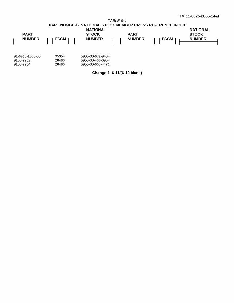
TM 11-6625-2866-14&PTABLE 6-4
PART NUMBER - NATIONAL STOCK NUMBER CROSS REFERENCE INDEXNATIONAL NATIONAL
PART STOCK PART STOCKNUMBER FSCM NUMBER NUMBER FSCM NUMBER
91-6915-1500-00 95354 5935-00-972-94649100-2252 28480 5950-00-430-69049100-2254 28480 5950-00-008-4471
Change 1 6-11/(6-12 blank)
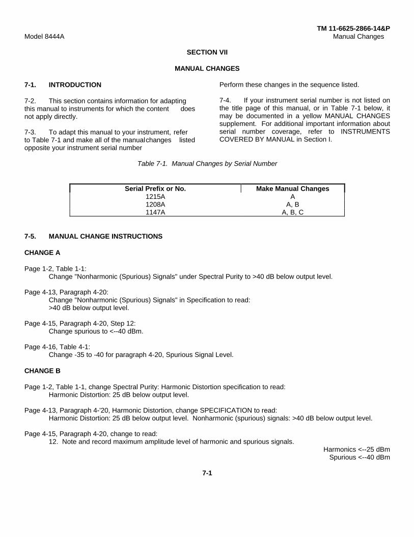
TM 11-6625-2866-14&PModel 8444A Manual Changes
SECTION VII
MANUAL CHANGES
7-1. INTRODUCTION
7-2. This section contains information for adaptingthis manual to instruments for which the content doesnot apply directly.
7-3. To adapt this manual to your instrument, referto Table 7-1 and make all of the manualchanges listedopposite your instrument serial number
Perform these changes in the sequence listed.
7-4. If your instrument serial number is not listed onthe title page of this manual, or in Table 7-1 below, itmay be documented in a yellow MANUAL CHANGESsupplement. For additional important information aboutserial number coverage, refer to INSTRUMENTSCOVERED BY MANUAL in Section I.
Table 7-1. Manual Changes by Serial Number
Serial Prefix or No. Make Manual Changes1215A A1208A A, B1147A A, B, C
7-5. MANUAL CHANGE INSTRUCTIONS
CHANGE A
Page 1-2, Table 1-1:Change "Nonharmonic (Spurious) Signals" under Spectral Purity to >40 dB below output level.
Page 4-13, Paragraph 4-20:Change "Nonharmonic (Spurious) Signals" in Specification to read:>40 dB below output level.
Page 4-15, Paragraph 4-20, Step 12:Change spurious to <--40 dBm.
Page 4-16, Table 4-1:Change -35 to -40 for paragraph 4-20, Spurious Signal Level.
CHANGE B
Page 1-2, Table 1-1, change Spectral Purity: Harmonic Distortion specification to read:Harmonic Distortion: 25 dB below output level.
Page 4-13, Paragraph 4-'20, Harmonic Distortion, change SPECIFICATION to read:Harmonic Distortion: 25 dB below output level. Nonharmonic (spurious) signals: >40 dB below output level.
Page 4-15, Paragraph 4-20, change to read:12. Note and record maximum amplitude level of harmonic and spurious signals.
Harmonics <--25 dBmSpurious <--40 dBm
7-1
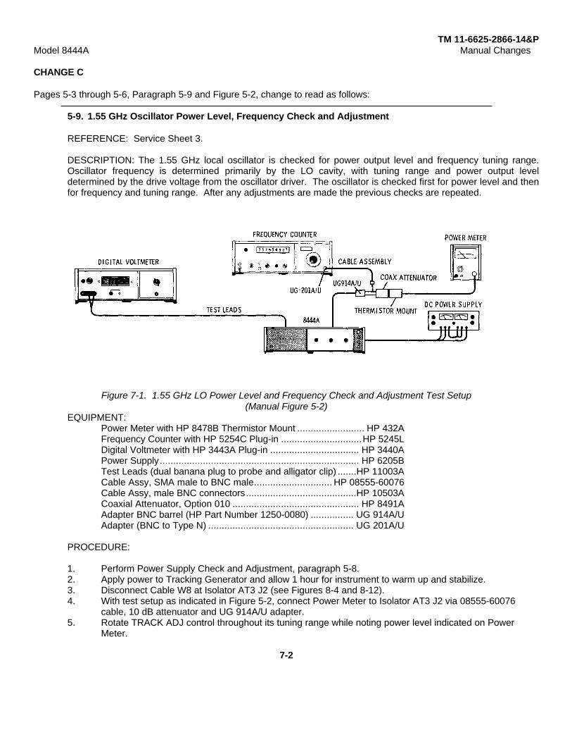
TM 11-6625-2866-14&PModel 8444A Manual Changes
CHANGE C
Pages 5-3 through 5-6, Paragraph 5-9 and Figure 5-2, change to read as follows:
5-9. 1.55 GHz Oscillator Power Level, Frequency Check and Adjustment
REFERENCE: Service Sheet 3.
DESCRIPTION: The 1.55 GHz local oscillator is checked for power output level and frequency tuning range.Oscillator frequency is determined primarily by the LO cavity, with tuning range and power output leveldetermined by the drive voltage from the oscillator driver. The oscillator is checked first for power level and thenfor frequency and tuning range. After any adjustments are made the previous checks are repeated.
Figure 7-1. 1.55 GHz LO Power Level and Frequency Check and Adjustment Test Setup(Manual Figure 5-2)
EQUIPMENT:Power Meter with HP 8478B Thermistor Mount ......................... HP 432AFrequency Counter with HP 5254C Plug-in ..............................HP 5245LDigital Voltmeter with HP 3443A Plug-in ................................. HP 3440APower Supply.......................................................................... HP 6205BTest Leads (dual banana plug to probe and alligator clip) .......HP 11003ACable Assy, SMA male to BNC male............................. HP 08555-60076Cable Assy, male BNC connectors.........................................HP 10503ACoaxial Attenuator, Option 010 ............................................... HP 8491AAdapter BNC barrel (HP Part Number 1250-0080) ................ UG 914A/UAdapter (BNC to Type N) ...................................................... UG 201A/U
PROCEDURE:
1. Perform Power Supply Check and Adjustment, paragraph 5-8.2. Apply power to Tracking Generator and allow 1 hour for instrument to warm up and stabilize.3. Disconnect Cable W8 at Isolator AT3 J2 (see Figures 8-4 and 8-12).4. With test setup as indicated in Figure 5-2, connect Power Meter to Isolator AT3 J2 via 08555-60076
cable, 10 dB attenuator and UG 914A/U adapter.5. Rotate TRACK ADJ control throughout its tuning range while noting power level indicated on Power
Meter.
7-2
TM 11-6625-2866-14&PModel 8444A Manual Changes
5-9. 1.55 GHz Oscillator Power Level, Frequency Check and Adjustment (cont'd)
6. Record minimum power output.>+5 dBm
7. Connect Frequency Counter to Isolator AT3 J2 via 08555-60076 cable, UG 914A/1J adapter and BNC toBNC cable.
8. Rotate TRACK ADJ control fully counterclockwise and record oscillator frequency.1,548,000+500 kHz
9. Rotate TRACK ADJ control fully clockwise and record oscillator frequency.1,552,000+500 kHz
10. Record frequency tuning range (frequency recorded in step 9 minus frequency recorded in step 8).4,000+500 kHz
11. If data recorded in steps 6, 8, 9, and 10 is within tolerance no adjustment is required.
12. If power level recorded in step 6 is less than +5 dBm proceed to step 23.
13. If data recorded in steps 8, 9, or 10 is not within tolerance proceed with step 14.
14. Connect Digital Voltmeter to test point A2TP5.
15. Set TRACK ADJ -control fully clockwise. Set "MAX" TUNE potentiometer A2R26 fully counterclockwise.
16. Adjust "MIN" TUNE potentiometer A2R27 to set voltage at test point A2I'P5 to level indicated onoscillator label. (See steps 23 through 30 for method of obtaining voltage level.)
17. Measure and record oscillator frequency.
18. Adjust "MAX" TUNE potentiometer to increase oscillator frequency 4, 000+50 kHz above frequencyrecorded in step 17. Record oscillator frequency.
19. Set TRACK ADJ control to center of tuning range recorded in steps 17 and 18 above. Record oscillatorfrequency.
20. If frequency recorded in step 19 is not within +500 kHz of 1.550 GHz adjust A7ADJ 1 to tune oscillatorfrequency to 1.550 GHz +100 kHz.
21. If oscillator frequency is adjusted, repeat steps 15 through 20.
22. Repeat steps 4 through 11 above.
23. If power level recorded in step 6 is less than +5 dBm connect Power Meter as indicated in step 4.Remove right side panel cover. Unsolder and remove power wires from A7C2 and A7C3.
24. Adjust Power Supply for -10 and +10 volts. Connect -10 volts to A7C3 and +10 volts to A7C2. ConnectPower Supply ground to solder lug near A7 Oscillator Assembly.
7-3
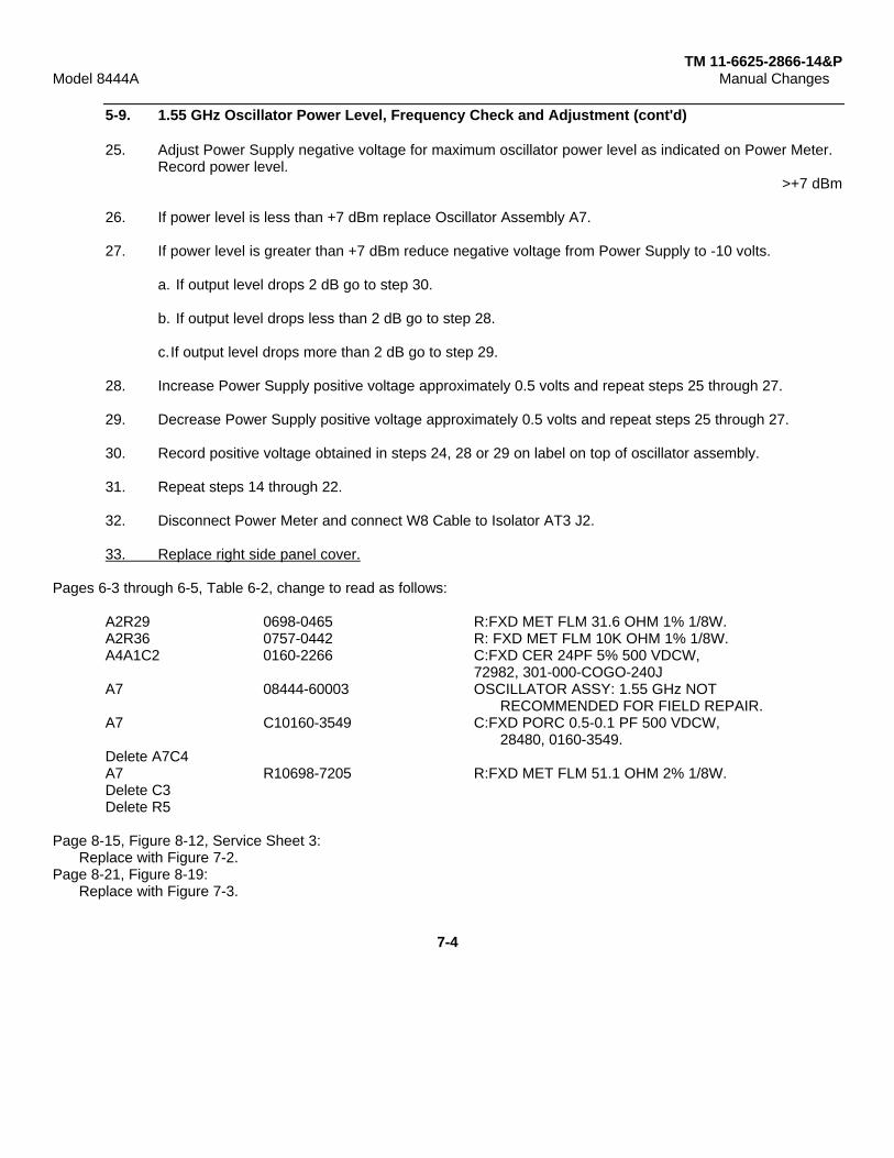
TM 11-6625-2866-14&PModel 8444A Manual Changes
5-9. 1.55 GHz Oscillator Power Level, Frequency Check and Adjustment (cont'd)
25. Adjust Power Supply negative voltage for maximum oscillator power level as indicated on Power Meter.Record power level.
>+7 dBm
26. If power level is less than +7 dBm replace Oscillator Assembly A7.
27. If power level is greater than +7 dBm reduce negative voltage from Power Supply to -10 volts.
a. If output level drops 2 dB go to step 30.
b. If output level drops less than 2 dB go to step 28.
c.If output level drops more than 2 dB go to step 29.
28. Increase Power Supply positive voltage approximately 0.5 volts and repeat steps 25 through 27.
29. Decrease Power Supply positive voltage approximately 0.5 volts and repeat steps 25 through 27.
30. Record positive voltage obtained in steps 24, 28 or 29 on label on top of oscillator assembly.
31. Repeat steps 14 through 22.
32. Disconnect Power Meter and connect W8 Cable to Isolator AT3 J2.
33. Replace right side panel cover.
Pages 6-3 through 6-5, Table 6-2, change to read as follows:
A2R29 0698-0465 R:FXD MET FLM 31.6 OHM 1% 1/8W.A2R36 0757-0442 R: FXD MET FLM 10K OHM 1% 1/8W.A4A1C2 0160-2266 C:FXD CER 24PF 5% 500 VDCW,
72982, 301-000-COGO-240JA7 08444-60003 OSCILLATOR ASSY: 1.55 GHz NOT
RECOMMENDED FOR FIELD REPAIR.A7 C10160-3549 C:FXD PORC 0.5-0.1 PF 500 VDCW,
28480, 0160-3549.Delete A7C4A7 R10698-7205 R:FXD MET FLM 51.1 OHM 2% 1/8W.Delete C3Delete R5
Page 8-15, Figure 8-12, Service Sheet 3:Replace with Figure 7-2.
Page 8-21, Figure 8-19:Replace with Figure 7-3.
7-4
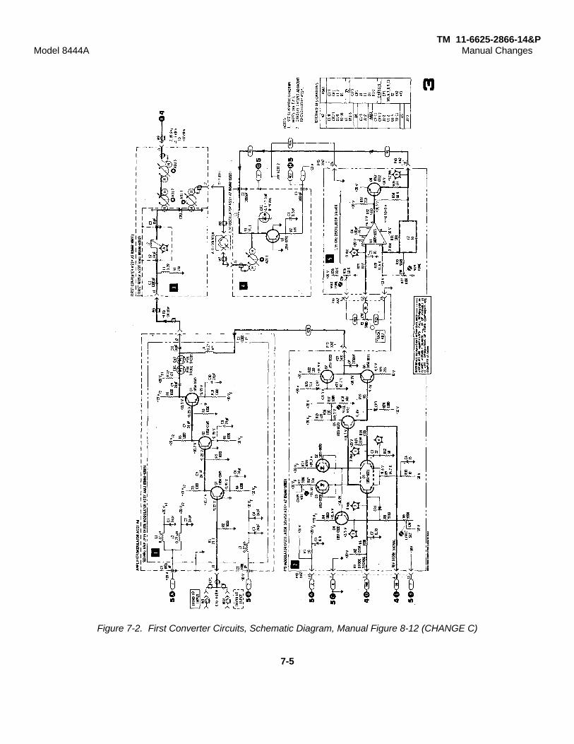
TM 11-6625-2866-14&PModel 8444A Manual Changes
Figure 7-2. First Converter Circuits, Schematic Diagram, Manual Figure 8-12 (CHANGE C)
7-5

TM 11-6625-2866-14&PModel 8444A Manual Changes
Figure 7-3. A 7 1.55 GHz Oscillator Assembly, Illustrated Parts Breakdown, Manual Figure 8-19 (1 of 2) (for Change C)
7-6

TM 11-6625-2866-14&PModel 8444A Manual Changes
7-6. MANUAL CHANGE SUPPLEMENT
This supplement contains important information for adapting the manual to instruments containing improvements madeafter the printing of the manual.
To use this supplement:
Make all appropriate serial number related changes indicated in the tables below.
Serial Prefix or Number Make Manual Changes Serial Prefix or Number Make ManualChanges
1601A, 1630A 1
CHANGE 1
Page 6-6, Table 6-2:Change A8 HP Part Number to 0960-0444.
Page 6-7, Table 6-2:Change SI HP Part Number to 3101-1395.
Page 8-19, Figure 8-17, Service Sheet 5:Replace ON/OFF switch S1 and POWER LINE MODULE A8, wiring diagram and schematic, with Figure 1 of thisMANUAL CHANGES.
7-7
TM 11-6625-2866-14&PModel 8444A Service
SECTION VIII
SERVICE
8-1. INTRODUCTION8-2. This section provides instructions for trouble-shooting and repair of the HP Model 8444A TrackingGenerator.8-3. PRINCIPLES OF OPERATION8-4. Information relative to the principles ofoperation appears on the foldout pages opposing theBlock Diagram, Service Sheet 1. Theory of operationappears on the foldout pages facing each of the foldoutschematic diagrams. The schematic diagram circuitsare referenced in the theory of operation test by blocknumbers.8-5. RECOMMENDED TEST EQUIPMENT8-6. Test equipment and accessories required tomaintain the Tracking Generator are listed in Table 1-3.If the equipment listed is not available, equipment thatmeets the required specifications may be substituted.8-7. TROUBLESHOOTING8-8. Troubleshooting procedures are divided into twomaintenance levels in this manual. The first, atroubleshooting tree, is designed to isolate themalfunction to the defective circuit.8-9. The second maintenance level provides circuitanalysis and test procedures to aid in isolating faults to adefective component. Circuit descriptions and testprocedures for the second maintenance level arelocated on the pages facing the schematic diagrams.The test procedures are referenced to the schematicdiagrams by block numbers.8-10. After the cause of a malfunction has been foundand remedied in any circuit containing adjustablecomponents, the applicable procedure specified inSection V of this manual should be performed. Afterrepairs and/or adjustments have been made, theapplicable procedure specified in Section IV of thismanual should be performed.8-11. REPAIR8-12. Factory Repaired Exchange Modules. TheLSI microcircuit, Amplifier and ALC Detector Assy A3, isavailable as a factory repaired exchange module. Thefactory repaired module is available at a considerablesavings in cost over the new module.
8-13 This exchange module should be ordered fromthe nearest Hewlett-Packard Sales and Service officeusing the part number in the replaceable parts table inSection VI of this manual. Virtually all orders forreplacement parts received by HP offices are shippedthe same day received --either from the local office orfrom a Service Center.8-14. Factory Selected Components. Somecomponent values are selected at the time of finalcheckout at the factory. Usually these values are notextremely critical; they are selected to provide optimumcompatibility with associated components. Thesecomponents, which are identified on the schematics withan asterisk, are listed in Table 84. The recommendedprocedure for replacing a factory-selected component isas follows:
a. Try the original value, then perform the testspecified in Section. V of this manual for the circuitbeing repaired.
b. If the specified test cannot be satisfactorilyperformed, try the typical value shown in the parts listand repeat the test.
c. If the test results are still not satisfactory,substitute various values until the desired result isobtained.
8-15. Adjustable Components. Adjustablecomponents, other than front panel operating controls,are listed in Table 8-2 Adjustment procedures for thesecomponents are contained in Section V of this manual.8-16. Servicing Aids on Printed Circuit Boards.Servicing aids on printed circuit boards include testpoints, transistor designations, adjustment callouts andassembly part numbers with alpha-numerical revisioninformation.8-17. Part Location Aids. The location of chassismounted parts and major assemblies are shown inFigures 8-4 and 8-5.
8-18. The location of individual components mountedon printed circuit boards or assemblies are shown on theappropriate Service Sheet. The part referencedesignator is the assembly designation plus the partdesignation. (Example: A1Rl is R1 on the Alassembly.) For specific component description andordering information refer to the replaceable parts tablein Section VI.
8-1
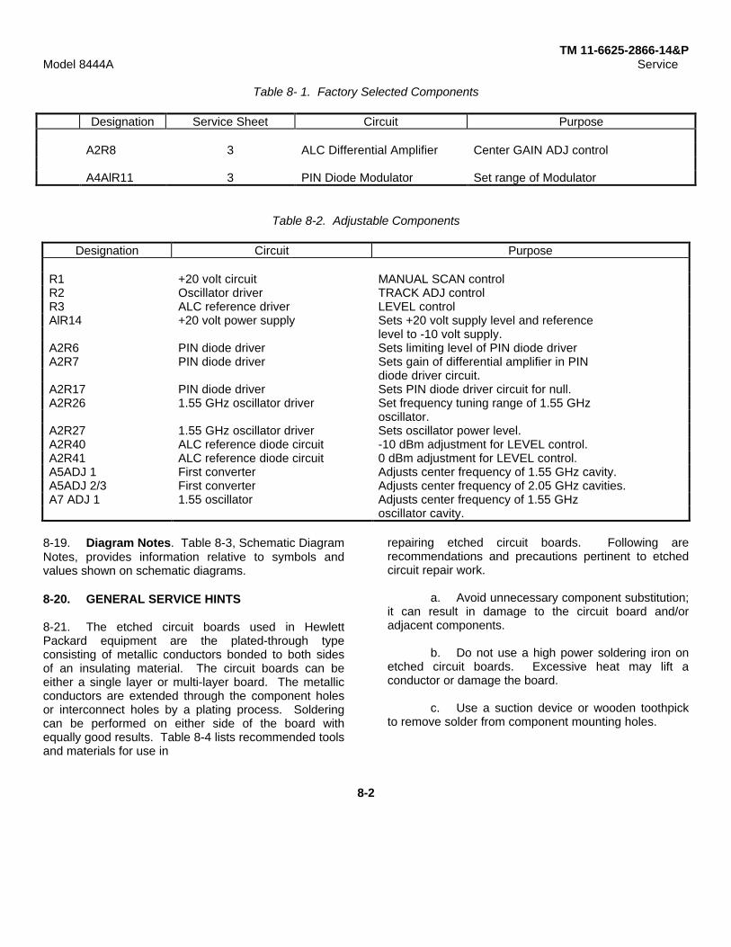
TM 11-6625-2866-14&PModel 8444A Service
Table 8- 1. Factory Selected Components
Designation Service Sheet Circuit Purpose
A2R8 3 ALC Differential Amplifier Center GAIN ADJ control
A4AlR11 3 PIN Diode Modulator Set range of Modulator
Table 8-2. Adjustable Components
Designation Circuit Purpose
R1 +20 volt circuit MANUAL SCAN controlR2 Oscillator driver TRACK ADJ controlR3 ALC reference driver LEVEL controlAlR14 +20 volt power supply Sets +20 volt supply level and reference
level to -10 volt supply.A2R6 PIN diode driver Sets limiting level of PIN diode driverA2R7 PIN diode driver Sets gain of differential amplifier in PIN
diode driver circuit.A2R17 PIN diode driver Sets PIN diode driver circuit for null.A2R26 1.55 GHz oscillator driver Set frequency tuning range of 1.55 GHz
oscillator.A2R27 1.55 GHz oscillator driver Sets oscillator power level.A2R40 ALC reference diode circuit -10 dBm adjustment for LEVEL control.A2R41 ALC reference diode circuit 0 dBm adjustment for LEVEL control.A5ADJ 1 First converter Adjusts center frequency of 1.55 GHz cavity.A5ADJ 2/3 First converter Adjusts center frequency of 2.05 GHz cavities.A7 ADJ 1 1.55 oscillator Adjusts center frequency of 1.55 GHz
oscillator cavity.
8-19. Diagram Notes. Table 8-3, Schematic DiagramNotes, provides information relative to symbols andvalues shown on schematic diagrams.
8-20. GENERAL SERVICE HINTS
8-21. The etched circuit boards used in HewlettPackard equipment are the plated-through typeconsisting of metallic conductors bonded to both sidesof an insulating material. The circuit boards can beeither a single layer or multi-layer board. The metallicconductors are extended through the component holesor interconnect holes by a plating process. Solderingcan be performed on either side of the board withequally good results. Table 8-4 lists recommended toolsand materials for use in
repairing etched circuit boards. Following arerecommendations and precautions pertinent to etchedcircuit repair work.
a. Avoid unnecessary component substitution;it can result in damage to the circuit board and/oradjacent components.
b. Do not use a high power soldering iron onetched circuit boards. Excessive heat may lift aconductor or damage the board.
c. Use a suction device or wooden toothpickto remove solder from component mounting holes.
8-2

TM 11-6625-2866-14&PModel 8444A Service
Table 8-3. Schematic Diagram Notes
8-3
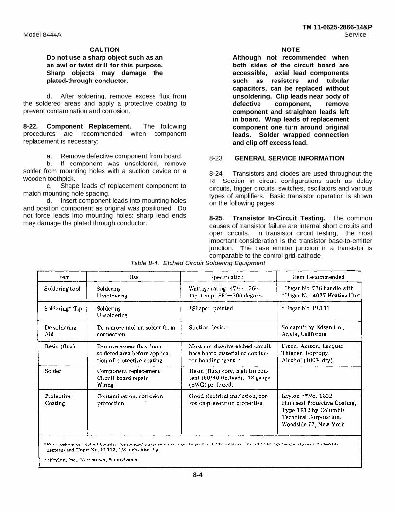
TM 11-6625-2866-14&PModel 8444A Service
CAUTIONDo not use a sharp object such as anan awl or twist drill for this purpose.Sharp objects may damage theplated-through conductor.
d. After soldering, remove excess flux fromthe soldered areas and apply a protective coating toprevent contamination and corrosion.
8-22. Component Replacement. The followingprocedures are recommended when componentreplacement is necessary:
a. Remove defective component from board.b. If component was unsoldered, remove
solder from mounting holes with a suction device or awooden toothpick.
c. Shape leads of replacement component tomatch mounting hole spacing.
d. Insert component leads into mounting holesand position component as original was positioned. Donot force leads into mounting holes: sharp lead endsmay damage the plated through conductor.
NOTEAlthough not recommended whenboth sides of the circuit board areaccessible, axial lead componentssuch as resistors and tubularcapacitors, can be replaced withoutunsoldering. Clip leads near body ofdefective component, removecomponent and straighten leads leftin board. Wrap leads of replacementcomponent one turn around originalleads. Solder wrapped connectionand clip off excess lead.
8-23. GENERAL SERVICE INFORMATION
8-24. Transistors and diodes are used throughout theRF Section in circuit configurations such as delaycircuits, trigger circuits, switches, oscillators and varioustypes of amplifiers. Basic transistor operation is shownon the following pages.
8-25. Transistor In-Circuit Testing. The commoncauses of transistor failure are internal short circuits andopen circuits. In transistor circuit testing, the mostimportant consideration is the transistor base-to-emitterjunction. The base emitter junction in a transistor iscomparable to the control grid-cathode
Table 8-4. Etched Circuit Soldering Equipment
8-4
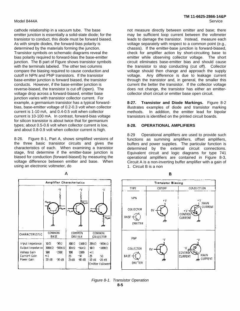
TM 11-6625-2866-14&PModel 8444A Service
cathode relationship in a vacuum tube. The baseemitter junction is essentially a solid-state diode; for thetransistor to conduct, this diode must be forward biased.As with simple diodes, the forward-bias polarity isdetermined by the materials forming the junction.Transistor symbols on schematic diagrams reveal thebias polarity required to forward-bias the base-emitterjunction. The B part of Figure shows transistor symbolswith the terminals labeled. The other two columnscompare the biasing required to cause conduction andcutoff in NPN and PNP transistors. If the transistorbase-emitter junction is forward biased, the transistorconducts. However, if the base-emitter junction isreverse-biased, the transistor is cut off (open). Thevoltage drop across a forward-biased, emitter basejunction varies with transistor collector current. Forexample, a germanium transistor has a typical forward-bias, base-emitter voltage of 0.2-0.3 volt when collectorcurrent is 1-10 mA, and 0.4-0.5 volt when collectorcurrent is 10-100 mA. In contrast, forward-bias voltagefor silicon transistor is about twice that for germaniumtypes; about 0.5-0.6 volt when collector current is low,and about 0.8-0.9 volt when collector current is high.
8-26. Figure 8-1, Part A, shows simplified versions ofthe three basic transistor circuits and gives thecharacteristics of each. When examining a transistorstage, first determine if the emitter-base junction isbiased for conduction (forward-biased) by measuring thevoltage difference between emitter and base. Whenusing an electronic voltmeter, do
not measure directly between emitter and base; theremay be sufficient loop current between the voltmeterleads to damage the transistor. Instead, measure eachvoltage separately with respect to a common point (e.g.,chassis). If the emitter-base junction is forward-biased,check for amplifier action by short-circuiting base toemitter while observing collector voltage. The shortcircuit eliminates base-emitter bias and should causethe transistor to stop conducting (cut off). Collectorvoltage should then change and approach the supplyvoltage. Any difference is due to leakage currentthrough the transistor and, in general, the smaller thiscurrent the better the transistor. If the collector voltagedoes not change, the transistor has either an emitter-collector short circuit or emitter base open circuit.
8-27. Transistor and Diode Markings. Figure 8-2illustrates examples of diode and transistor markingmethods. In addition, the emitter lead for bipolartransistors is identified on the printed circuit boards.
8-28. OPERATIONAL AMPLIFIERS
8-29 Operational amplifiers are used to provide suchfunctions as summing amplifiers, offset amplifiers,buffers and power supplies. The particular function isdetermined by the external circuit connections.Equivalent circuit and logic diagrams for type 741operational amplifiers are contained in Figure 8-3,Circuit A is a non-inverting buffer amplifier with a gain of1. Circuit B is a non
Figure 8-1. Transistor Operation8-5
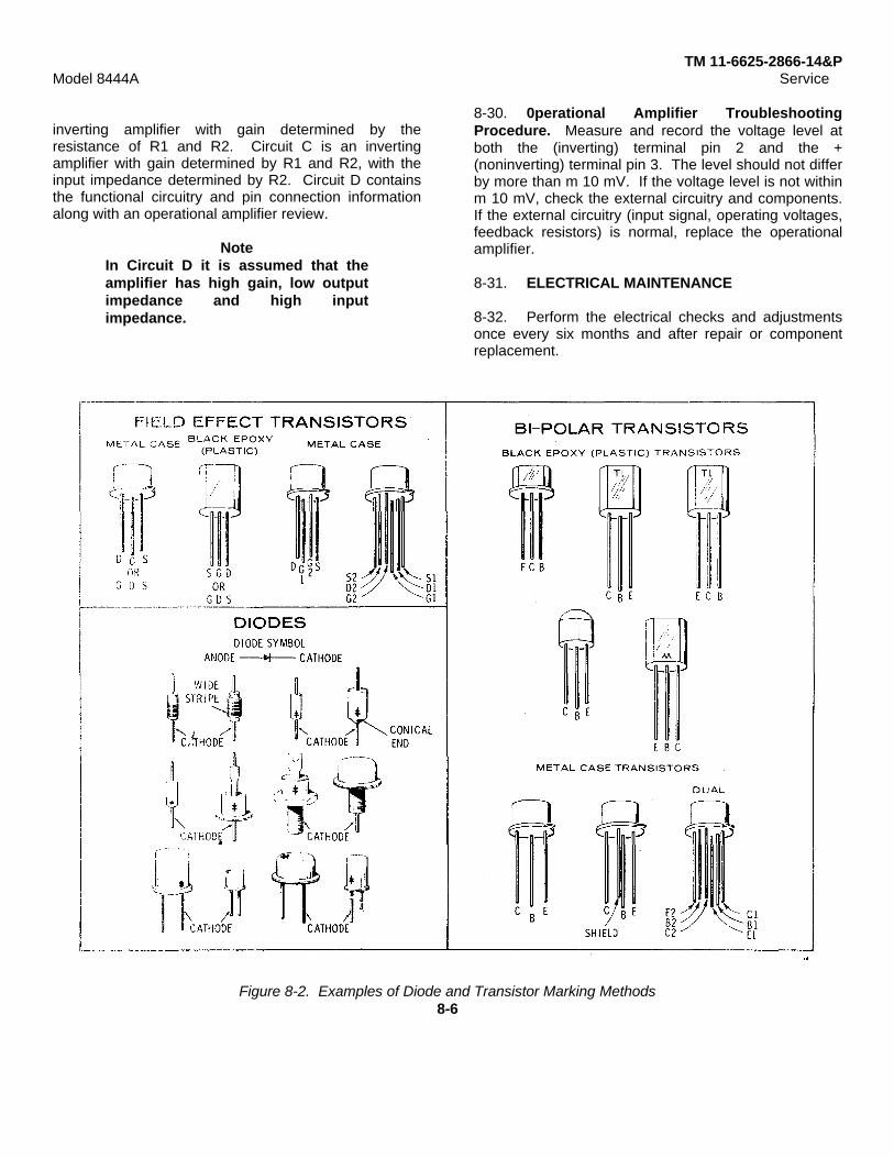
TM 11-6625-2866-14&PModel 8444A Service
inverting amplifier with gain determined by theresistance of R1 and R2. Circuit C is an invertingamplifier with gain determined by R1 and R2, with theinput impedance determined by R2. Circuit D containsthe functional circuitry and pin connection informationalong with an operational amplifier review.
NoteIn Circuit D it is assumed that theamplifier has high gain, low outputimpedance and high inputimpedance.
8-30. 0perational Amplifier TroubleshootingProcedure. Measure and record the voltage level atboth the (inverting) terminal pin 2 and the +(noninverting) terminal pin 3. The level should not differby more than m 10 mV. If the voltage level is not withinm 10 mV, check the external circuitry and components.If the external circuitry (input signal, operating voltages,feedback resistors) is normal, replace the operationalamplifier.
8-31. ELECTRICAL MAINTENANCE
8-32. Perform the electrical checks and adjustmentsonce every six months and after repair or componentreplacement.
Figure 8-2. Examples of Diode and Transistor Marking Methods8-6

TM 11-6625-2866-14&PModel 8444A Service
Figure 8-3. Operational Amplifier Equivalent Circuit8-7/8-8

TM 11-6625-286614&P
Figure 8-4. Major Assembly Locations (1 Figure 8-4. Major Assembly Locations Figure 8-5. Adjustment and Test Point
8-9

TM 11-6625-286614&P
Figure 8-6.Tracking Generator Spectrum Analyzer, Simplified Block Diagram
8-10
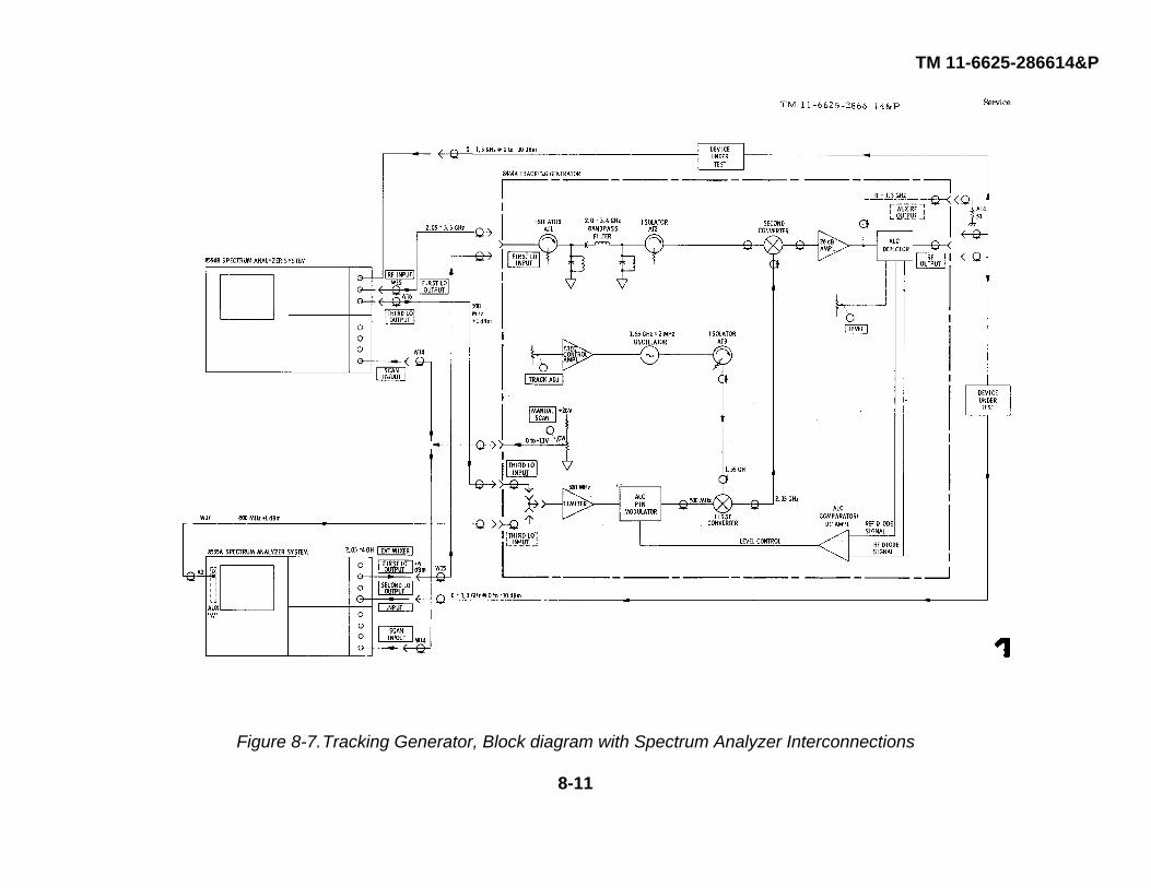
TM 11-6625-286614&P
Figure 8-7.Tracking Generator, Block diagram with Spectrum Analyzer Interconnections
8-11
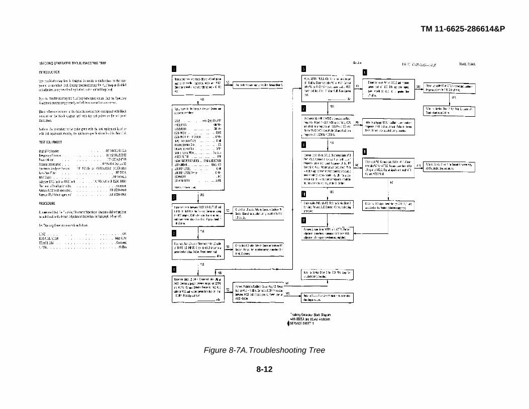
TM 11-6625-286614&P
Figure 8-7A.Troubleshooting Tree
8-12

TM 11-6625-286614&P
Figure 8-8.Tracking Generator Troubleshooting Block Diagram
8-13

TM 11-6625-286614&P
Figure 8-9. Mixer Diode FormingDimensions in Inches
8-14

TM 11-8520-759-35
Figure 8-12. First Converter Circuits, Schematic Diagram
Figure 8-10. Modulator/Oscillator DriverAssy A2 Component Locations
Figure 8-11. Amplifier and Pin DiodeModulator Assy A4A1 Component Locations
8-15
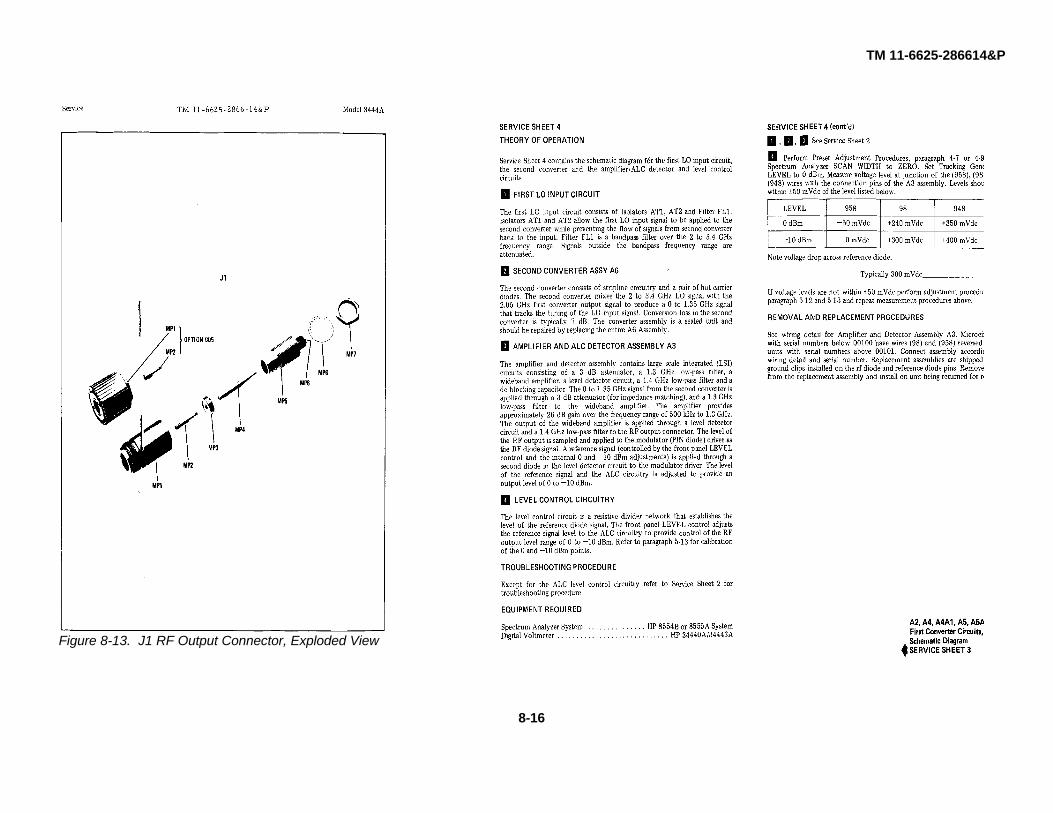
TM 11-6625-286614&P
Figure 8-13. J1 RF Output Connector, Exploded View
8-16

TM 11-6625-286614&P
Figure 8-14. A2 Modulator/Oscillator Driver Assy, Component LocationFigure 8-15. Second Converter Circuit, Schematic Diagram
8-17
TM 11-6625-286614&P
8-18
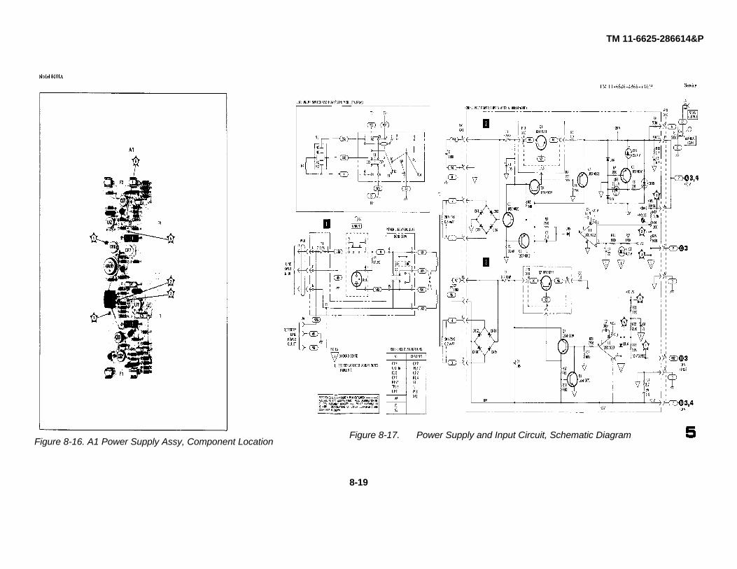
TM 11-6625-286614&P
Figure 8-16. A1 Power Supply Assy, Component LocationFigure 8-17. Power Supply and Input Circuit, Schematic Diagram
8-19

TM 11-6625-286614&P
Figure 8-18. A5 First Converter Assembly, Illustrated Parts Breakdown (1 of 2)
Figure 8-18. A5 First Converter Assembly, Illustrated Parts Breakdown (2 of 2)
8-20
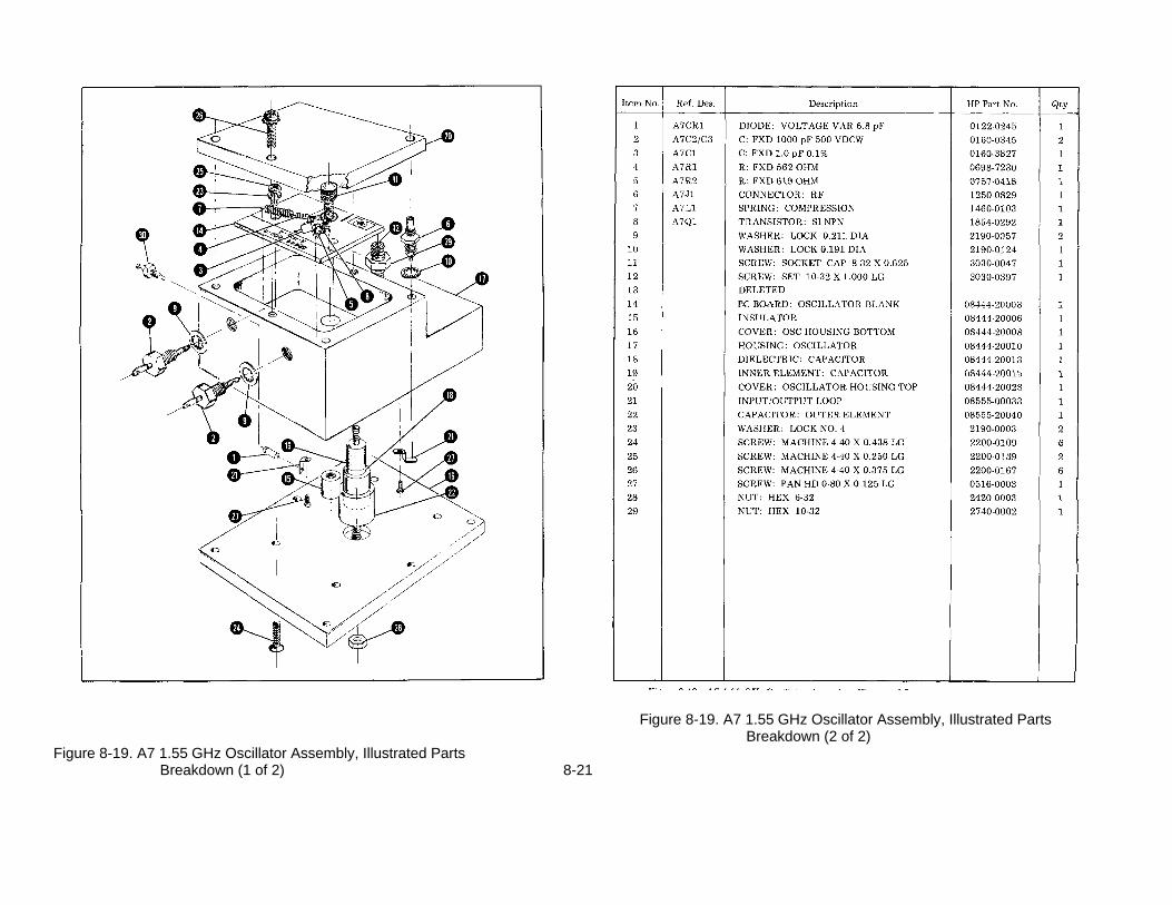
Figure 8-19. A7 1.55 GHz Oscillator Assembly, Illustrated PartsBreakdown (2 of 2)
Figure 8-19. A7 1.55 GHz Oscillator Assembly, Illustrated PartsBreakdown (1 of 2) 8-21

TM 11-6625-2866-14&PModel 8444A Appendix A
APPENDIX A
SERVICE NOTE - P-0960-2038, P-5086-6025
HP MODEL 8444A TRACKING GENERATOR
Serials Prefixed 1147A and Below
REQUIRED MODIFICATION WHEN REPLACING A3
When replacing the A3 Amplifier Detector Assembly in the HP Model 8444A, serials prefixed 1147A and below, a capacitor C3, 3300 pF, HP Part No. 0160-0155, is a required addition for proper instrument operation. The capacitor is electrically connected between the RF Diode Signal line and ground. For easiestinstallation, connect the capacitor between connector pins XA2-1 and XA2-7. Pin 1 is located nearest the instrument front panel.
APPENDIX B
SERVICE NOTE - P-08444-60019
HP MODEL 8444A TRACKING GENERATOR
Serials Prefixed 1147A and Below
REPLACEMENT FOR A7 08444-60003
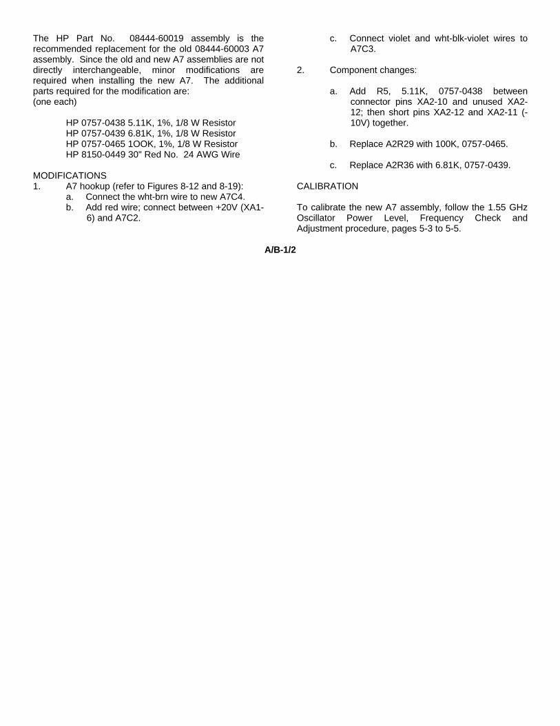
The HP Part No. 08444-60019 assembly is therecommended replacement for the old 08444-60003 A7assembly. Since the old and new A7 assemblies are notdirectly interchangeable, minor modifications arerequired when installing the new A7. The additionalparts required for the modification are:(one each)
HP 0757-0438 5.11K, 1%, 1/8 W ResistorHP 0757-0439 6.81K, 1%, 1/8 W ResistorHP 0757-0465 1OOK, 1%, 1/8 W ResistorHP 8150-0449 30" Red No. 24 AWG Wire
MODIFICATIONS1. A7 hookup (refer to Figures 8-12 and 8-19):
a. Connect the wht-brn wire to new A7C4.b. Add red wire; connect between +20V (XA1-
6) and A7C2.
c. Connect violet and wht-blk-violet wires toA7C3.
2. Component changes:
a. Add R5, 5.11K, 0757-0438 betweenconnector pins XA2-10 and unused XA2-12; then short pins XA2-12 and XA2-11 (-10V) together.
b. Replace A2R29 with 100K, 0757-0465.
c. Replace A2R36 with 6.81K, 0757-0439.
CALIBRATION
To calibrate the new A7 assembly, follow the 1.55 GHzOscillator Power Level, Frequency Check andAdjustment procedure, pages 5-3 to 5-5.
A/B-1/2
TM 11-6625-2866-14&PModel 8444A Appendix C
APPENDIX C
SERVICE NOTE - 8444A-1
HP MODEL 8444A TRACKING GENERATOR
Serials Prefixed 1147A and Below
IMPROVED POWER SUPPLY STABILITY
The +20V power supply stability can be improved by changing A4A1C2 from 24 pF to 1000 pF, HP Part No. 0160-3456.The new value eliminates any oscillation tendencies and is a recommended modification for all instruments with serialslisted above.
C-1/2

TM 11-6625-2866-14&PModel 8444A Appendix D
APPENDIX D
MODEL 8444A TRACKING GENERATOR, OPTION 058
D-1. INTRODUCTION
D-2. This appendix explains the use of an 8444A Tracking Generator with an 8558B/180 Spectrum Analyzer systemwhen Option 058 circuitry is added to the 8444A. The Tracking Generator is designed to generate a CW tracking signalfor an 8555A/8552/140 Spectrum Analyzer system when operating in the range of 0.5 to 1300 MHz. With Option 058circuits added, a 0.5 to 1300 MHz CW tracking signal can also be generated by an 8444A when it is coupled to an8558B/180 Spectrum Analyzer system.
D-3. DESCRIPTION
D-4. To provide a tracking signal for an 8555A/8552/140 Spectrum Analyzer, an 8444A Tracking Generator must befed a 2.05 to 4.1 GHz tuned oscillator signal from the 8555A First LO, plus a 500 MHz signal from the 8555A Third LO.When mixed with the internal 1.55 GHz oscillator in the 8444A, a 0.5 to 1300 MHz tracking signal output is produced.
D-5. To develop a 0.5 to 1300 MHz tracking signal for an 8558B/180 Spectrum Analyzer/Display system, a 2.05 to3.55 GHz First LO is available from the 8558B, but no 500 MHz LO is used in this instrument. Option 058 consists of a500 MHz oscillator for the 8444A. This 500 MHz signal is brought out on a separate BNC connector on the rear panel ofthe 8444A, directly above the THIRD LO INPUT BNC connector. When the 8444A is used with an 8558B/180 SpectrumAnalyzer system, the two rear panel BNC connectors are interconnected with a short BNC cable. With the First LO fromthe 8558/B plus its own 500 MHz LO signal, the 8444A can provide a 0.5 to 1300 MHz tracking signal for the 8558BSpectrum Analyzer system.
D-6. MANUAL CHANGES TO INCORPORATE OPTION 058
D-7. Section I.
D-8. 8444A System Specifications with Option 058 added are listed in Table D-1.
Table D-1. 8444A System Specifications with Option 058
SPECIFICATIONS
These specifications apply to the 8444A Option 058 when used with the 8558B Spectrum Analyzer ONLY. Specificationsof the 8444A Option 058 when used with the 8554B and 8555A Spectrum Analyzers can be found in Table 1-1 of the8444A manual.
Swept Frequency Response Measurements Absolute Amplitude Calibration Range
Dynamic Range: <90 dB from Spectrum Analyzer 1 dB Spectrum Analyzer:gain compression point to average noise level (approxi-mately --10 dBm to -100 dBm). Log: From -117 dBm to +30 dBm, 10 dB/div on a
70 dB display or 1 dB/div on an 8 dB display.Average Noise Level: -107 dBm with 10 kHz Resolution Linear: From 2.2 µV (-100 dBm) to 7.1V (+30
bandwidth. dBm), full scale in 10 dB steps.
D-1
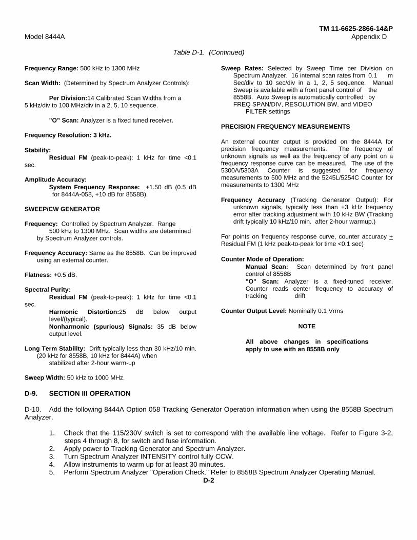
TM 11-6625-2866-14&PModel 8444A Appendix D
Table D-1. (Continued)
Frequency Range: 500 kHz to 1300 MHz
Scan Width: (Determined by Spectrum Analyzer Controls):
Per Division:14 Calibrated Scan Widths from a5 kHz/div to 100 MHz/div in a 2, 5, 10 sequence.
"O” Scan: Analyzer is a fixed tuned receiver.
Frequency Resolution: 3 kHz.
Stability:Residual FM (peak-to-peak): 1 kHz for time <0.1
sec.
Amplitude Accuracy:System Frequency Response: +1.50 dB (0.5 dBfor 8444A-058, +10 dB for 8558B).
SWEEP/CW GENERATOR
Frequency: Controlled by Spectrum Analyzer. Range500 kHz to 1300 MHz. Scan widths are determined
by Spectrum Analyzer controls.
Frequency Accuracy: Same as the 8558B. Can be improvedusing an external counter.
Flatness: +0.5 dB.
Spectral Purity:Residual FM (peak-to-peak): 1 kHz for time <0.1
sec.Harmonic Distortion:25 dB below outputlevel/(typical).Nonharmonic (spurious) Signals: 35 dB belowoutput level.
Long Term Stability: Drift typically less than 30 kHz/10 min.(20 kHz for 8558B, 10 kHz for 8444A) when
stabilized after 2-hour warm-up
Sweep Width: 50 kHz to 1000 MHz.
Sweep Rates: Selected by Sweep Time per Division onSpectrum Analyzer. 16 internal scan rates from 0.1 mSec/div to 10 sec/div in a 1, 2, 5 sequence. ManualSweep is available with a front panel control of the8558B. Auto Sweep is automatically controlled byFREQ SPAN/DIV, RESOLUTION BW, and VIDEO
FILTER settings
PRECISION FREQUENCY MEASUREMENTS
An external counter output is provided on the 8444A forprecision frequency measurements. The frequency ofunknown signals as well as the frequency of any point on afrequency response curve can be measured. The use of the5300A/5303A Counter is suggested for frequencymeasurements to 500 MHz and the 5245L/5254C Counter formeasurements to 1300 MHz
Frequency Accuracy (Tracking Generator Output): Forunknown signals, typically less than +3 kHz frequencyerror after tracking adjustment with 10 kHz BW (Trackingdrift typically 10 kHz/10 min. after 2-hour warmup.)
For points on frequency response curve, counter accuracy +Residual FM (1 kHz peak-to-peak for time <0.1 sec)
Counter Mode of Operation:Manual Scan: Scan determined by front panelcontrol of 8558B"O" Scan: Analyzer is a fixed-tuned receiver.Counter reads center frequency to accuracy oftracking drift
Counter Output Level: Nominally 0.1 Vrms
NOTE
All above changes in specificationsapply to use with an 8558B only
D-9. SECTION III OPERATION
D-10. Add the following 8444A Option 058 Tracking Generator Operation information when using the 8558B SpectrumAnalyzer.
1. Check that the 115/230V switch is set to correspond with the available line voltage. Refer to Figure 3-2,steps 4 through 8, for switch and fuse information.
2. Apply power to Tracking Generator and Spectrum Analyzer.3. Turn Spectrum Analyzer INTENSITY control fully CCW.4. Allow instruments to warm up for at least 30 minutes.5. Perform Spectrum Analyzer "Operation Check." Refer to 8558B Spectrum Analyzer Operating Manual.
D-2
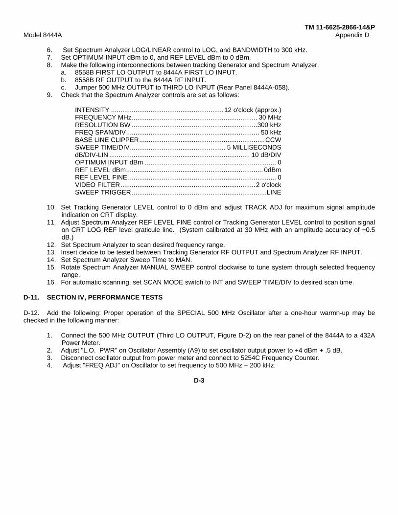
TM 11-6625-2866-14&PModel 8444A Appendix D
6. Set Spectrum Analyzer LOG/LINEAR control to LOG, and BANDWIDTH to 300 kHz.7. Set OPTIMUM INPUT dBm to 0, and REF LEVEL dBm to 0 dBm.8. Make the following interconnections between tracking Generator and Spectrum Analyzer.
a. 8558B FIRST LO OUTPUT to 8444A FIRST LO INPUT.b. 8558B RF OUTPUT to the 8444A RF INPUT.c. Jumper 500 MHz OUTPUT to THIRD LO INPUT (Rear Panel 8444A-058).
9. Check that the Spectrum Analyzer controls are set as follows:
INTENSITY ............................................................12 o'clock (approx.)FREQUENCY MHz................................................................... 30 MHzRESOLUTION BW ...................................................................300 kHzFREQ SPAN/DIV....................................................................... 50 kHzBASE LINE CLIPPER...................................................................CCWSWEEP TIME/DIV................................................... 5 MILLISECONDSdB/DIV-LIN ........................................................................... 10 dB/DIVOPTIMUM INPUT dBm ...................................................................... 0REF LEVEL dBm......................................................................... 0dBmREF LEVEL FINE............................................................................... 0VIDEO FILTER........................................................................2 o'clockSWEEP TRIGGER........................................................................LINE
10. Set Tracking Generator LEVEL control to 0 dBm and adjust TRACK ADJ for maximum signal amplitudeindication on CRT display.
11. Adjust Spectrum Analyzer REF LEVEL FINE control or Tracking Generator LEVEL control to position signalon CRT LOG REF level graticule line. (System calibrated at 30 MHz with an amplitude accuracy of +0.5dB.)
12. Set Spectrum Analyzer to scan desired frequency range.13. Insert device to be tested between Tracking Generator RF OUTPUT and Spectrum Analyzer RF INPUT.14. Set Spectrum Analyzer Sweep Time to MAN.15. Rotate Spectrum Analyzer MANUAL SWEEP control clockwise to tune system through selected frequency
range.16. For automatic scanning, set SCAN MODE switch to INT and SWEEP TIME/DIV to desired scan time.
D-11. SECTION IV, PERFORMANCE TESTS
D-12. Add the following: Proper operation of the SPECIAL 500 MHz Oscillator after a one-hour warmn-up may bechecked in the following manner:
1. Connect the 500 MHz OUTPUT (Third LO OUTPUT, Figure D-2) on the rear panel of the 8444A to a 432APower Meter.
2. Adjust "L.O. PWR" on Oscillator Assembly (A9) to set oscillator output power to +4 dBm + .5 dB.3. Disconnect oscillator output from power meter and connect to 5254C Frequency Counter.4. Adjust "FREQ ADJ" on Oscillator to set frequency to 500 MHz + 200 kHz.
D-3
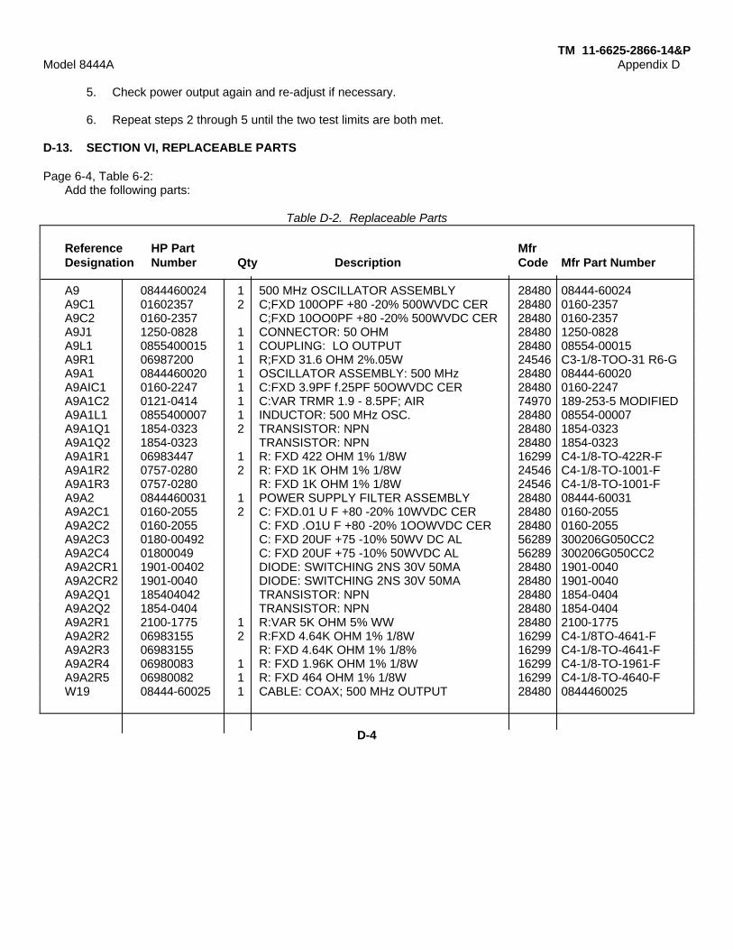
TM 11-6625-2866-14&PModel 8444A Appendix D
5. Check power output again and re-adjust if necessary.
6. Repeat steps 2 through 5 until the two test limits are both met.
D-13. SECTION VI, REPLACEABLE PARTS
Page 6-4, Table 6-2:Add the following parts:
Table D-2. Replaceable Parts
Reference HP Part MfrDesignation Number Qty Description Code Mfr Part Number
A9 0844460024 1 500 MHz OSCILLATOR ASSEMBLY 28480 08444-60024A9C1 01602357 2 C;FXD 100OPF +80 -20% 500WVDC CER 28480 0160-2357A9C2 0160-2357 C;FXD 10OO0PF +80 -20% 500WVDC CER 28480 0160-2357A9J1 1250-0828 1 CONNECTOR: 50 OHM 28480 1250-0828A9L1 0855400015 1 COUPLING: LO OUTPUT 28480 08554-00015A9R1 06987200 1 R;FXD 31.6 OHM 2%.05W 24546 C3-1/8-TOO-31 R6-GA9A1 0844460020 1 OSCILLATOR ASSEMBLY: 500 MHz 28480 08444-60020A9AIC1 0160-2247 1 C:FXD 3.9PF f.25PF 50OWVDC CER 28480 0160-2247A9A1C2 0121-0414 1 C:VAR TRMR 1.9 - 8.5PF; AIR 74970 189-253-5 MODIFIEDA9A1L1 0855400007 1 INDUCTOR: 500 MHz OSC. 28480 08554-00007A9A1Q1 1854-0323 2 TRANSISTOR: NPN 28480 1854-0323A9A1Q2 1854-0323 TRANSISTOR: NPN 28480 1854-0323A9A1R1 06983447 1 R: FXD 422 OHM 1% 1/8W 16299 C4-1/8-TO-422R-FA9A1R2 0757-0280 2 R: FXD 1K OHM 1% 1/8W 24546 C4-1/8-TO-1001-FA9A1R3 0757-0280 R: FXD 1K OHM 1% 1/8W 24546 C4-1/8-TO-1001-FA9A2 0844460031 1 POWER SUPPLY FILTER ASSEMBLY 28480 08444-60031A9A2C1 0160-2055 2 C: FXD.01 U F +80 -20% 10WVDC CER 28480 0160-2055A9A2C2 0160-2055 C: FXD .O1U F +80 -20% 1OOWVDC CER 28480 0160-2055A9A2C3 0180-00492 C: FXD 20UF +75 -10% 50WV DC AL 56289 300206G050CC2A9A2C4 01800049 C: FXD 20UF +75 -10% 50WVDC AL 56289 300206G050CC2A9A2CR1 1901-00402 DIODE: SWITCHING 2NS 30V 50MA 28480 1901-0040A9A2CR2 1901-0040 DIODE: SWITCHING 2NS 30V 50MA 28480 1901-0040A9A2Q1 185404042 TRANSISTOR: NPN 28480 1854-0404A9A2Q2 1854-0404 TRANSISTOR: NPN 28480 1854-0404A9A2R1 2100-1775 1 R:VAR 5K OHM 5% WW 28480 2100-1775A9A2R2 06983155 2 R:FXD 4.64K OHM 1% 1/8W 16299 C4-1/8TO-4641-FA9A2R3 06983155 R: FXD 4.64K OHM 1% 1/8% 16299 C4-1/8-TO-4641-FA9A2R4 06980083 1 R: FXD 1.96K OHM 1% 1/8W 16299 C4-1/8-TO-1961-FA9A2R5 06980082 1 R: FXD 464 OHM 1% 1/8W 16299 C4-1/8-TO-4640-FW19 08444-60025 1 CABLE: COAX; 500 MHz OUTPUT 28480 0844460025
D-4
TM 11-6625-2866-14&PModel 8444A Appendix D
D-14. SECTION VIII, SERVICE
D-15. Description of Option 058: A two-transistor, 500-MHz fixed-tuned local oscillator with power supply processingcircuits, Assembly A9, is added to the Main Deck of an 8444A. The 500 MHz LO Output is brought out through a BNCconnector on the rear panel directly above the BNC connector serving as the output of the THIRD LO INPUT. Powersupply voltages for the A9 500 MHz Oscillator Assembly are taken from the PC connector XA1 on the bottom of the8444A Main Deck.
D-16. Figure D-1 is a top view of the 8444A including the Option 058 500 MHz A9 Oscillator Assembly with its BNCconnector on the rear panel.
D-17. Figure D-2 shows the rear panel of an 8444A Option 058 with the added 500 MHz OUTPUT BNC connectorabove the THIRD LO INPUT connector.
D-18. Figure D-3 is a schematic diagram of the 500 MHz Oscillator used with Option 058, a capacitance multiplier usedas additional filter for the 8444A +20V power supply, and an adjustable current regulator for the -10V 8444A powersupply.
D-5

TM 11-6625-2866-14&PModel 8444A Appendix D
Figure D-1. 500 MHz LO Mounting location and Output Port for the 8444A, Option 058D-6

TM 11-6625-2866-14&PModel 844A Appendix D
When using the 8444A with an 8558B/180 Spectrum Analyzer the 8444A 500 MHz OUTPUT andits THRID LO INPUT must be interconnected with a short cable.
Figure D-2. Location of 500 MHz LO OUTPUT BNC Connector Added on Rear Panel of the 8444A, Option 058
D-7

TM 11-6625-2866-14&PModel 844A Appendix D
Figure D-3. A9 500 MHz Oscillator Assembly Schematic
D-8

TM 11-6625-2886-14&P
APPENDIX E
REFERENCES
DA Pam 310-4 Index of Technical Manuals, Technical Bulletins, Supply Manuals (Types 7, 8, and 9),Supply Bulletins, and Lubrication Orders.
DA Pam 310-7 US Army Equipment Index of Modification Work Orders.
TB 43-0118 Field Instructions for Painting and Preserving Electronics Command EquipmentIncluding Camouflage Pattern Painting of Electrical Equipment Shelters.
TM 38-750 The Army Maintenance Management System (TAMMS).
TM 750-244-2 Procedures for Destruction of Electronics Materiel to Prevent Enemy Use (ElectronicsCommand).
E-1
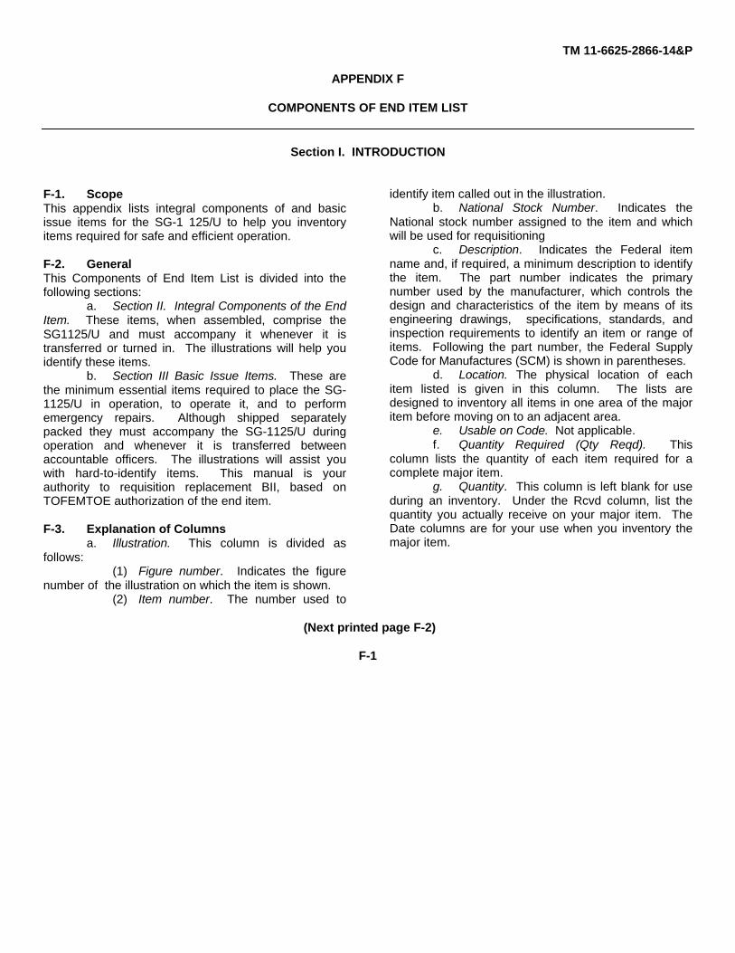
TM 11-6625-2866-14&P
APPENDIX F
COMPONENTS OF END ITEM LIST
Section I. INTRODUCTION
F-1. ScopeThis appendix lists integral components of and basicissue items for the SG-1 125/U to help you inventoryitems required for safe and efficient operation.
F-2. GeneralThis Components of End Item List is divided into thefollowing sections:
a. Section II. Integral Components of the EndItem. These items, when assembled, comprise theSG1125/U and must accompany it whenever it istransferred or turned in. The illustrations will help youidentify these items.
b. Section III Basic Issue Items. These arethe minimum essential items required to place the SG-1125/U in operation, to operate it, and to performemergency repairs. Although shipped separatelypacked they must accompany the SG-1125/U duringoperation and whenever it is transferred betweenaccountable officers. The illustrations will assist youwith hard-to-identify items. This manual is yourauthority to requisition replacement BII, based onTOFEMTOE authorization of the end item.
F-3. Explanation of Columnsa. Illustration. This column is divided as
follows:(1) Figure number. Indicates the figure
number of the illustration on which the item is shown.(2) Item number. The number used to
identify item called out in the illustration.b. National Stock Number. Indicates the
National stock number assigned to the item and whichwill be used for requisitioning
c. Description. Indicates the Federal itemname and, if required, a minimum description to identifythe item. The part number indicates the primarynumber used by the manufacturer, which controls thedesign and characteristics of the item by means of itsengineering drawings, specifications, standards, andinspection requirements to identify an item or range ofitems. Following the part number, the Federal SupplyCode for Manufactures (SCM) is shown in parentheses.
d. Location. The physical location of eachitem listed is given in this column. The lists aredesigned to inventory all items in one area of the majoritem before moving on to an adjacent area.
e. Usable on Code. Not applicable.f. Quantity Required (Qty Reqd). This
column lists the quantity of each item required for acomplete major item.
g. Quantity. This column is left blank for useduring an inventory. Under the Rcvd column, list thequantity you actually receive on your major item. TheDate columns are for your use when you inventory themajor item.
(Next printed page F-2)
F-1
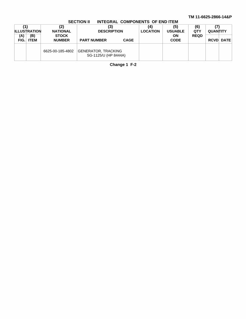
TM 11-6625-2866-14&PSECTION II INTEGRAL COMPONENTS OF END ITEM
(1) (2) (3) (4) (5) (6) (7)ILLUSTRATION NATIONAL DESCRIPTION LOCATION USUABLE QTY QUANTITY
(A) (B) STOCK ON REQDFIG. ITEM NUMBER PART NUMBER CAGE CODE RCVD DATE
6625-00-185-4802 GENERATOR, TRACKINGSG-1125/U (HP 8444A)
Change 1 F-2
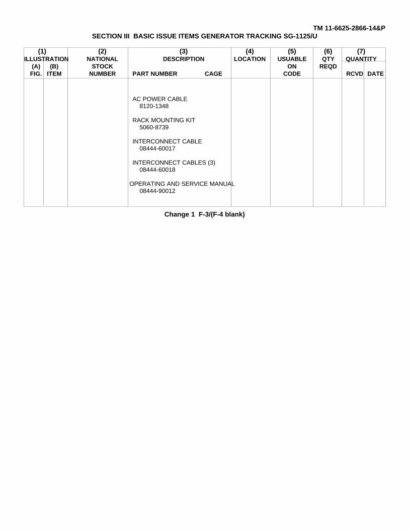
TM 11-6625-2866-14&PSECTION III BASIC ISSUE ITEMS GENERATOR TRACKING SG-1125/U
(1) (2) (3) (4) (5) (6) (7)ILLUSTRATION NATIONAL DESCRIPTION LOCATION USUABLE QTY QUANTITY
(A) (B) STOCK ON REQDFIG. ITEM NUMBER PART NUMBER CAGE CODE RCVD DATE
AC POWER CABLE 8120-1348
RACK MOUNTING KIT 5060-8739
INTERCONNECT CABLE 08444-60017
INTERCONNECT CABLES (3) 08444-60018
OPERATING AND SERVICE MANUAL 08444-90012
Change 1 F-3/(F-4 blank)
TM 11-6625-2866-14&P
APPENDIX G
ADDITIONAL AUTHORIZATION LIST
Section I. INTRODUCTION
G-1. ScopeThis appendix lists additional items you are authorizedfor the support of the SG-1 125/U.
G-2. GeneralThis list identifies items that do not have to accompanythe SG1125/U and that do not have to be turned in withit. These items are all authorized to you by CIA, MTOE,TDA, or JTA.
G-3. Explanation of ListingNational stock numbers, descriptions, and quantities areprovided to help you identify and request the additionalitems you require to support this equipment. The itemsare listed in alphabetical sequence by item name underthe type document i.e., CTA, MTOE, TDA, or ITA) whichauthorizes the item(s) to you.
(Next printed page is G-2)
G-1
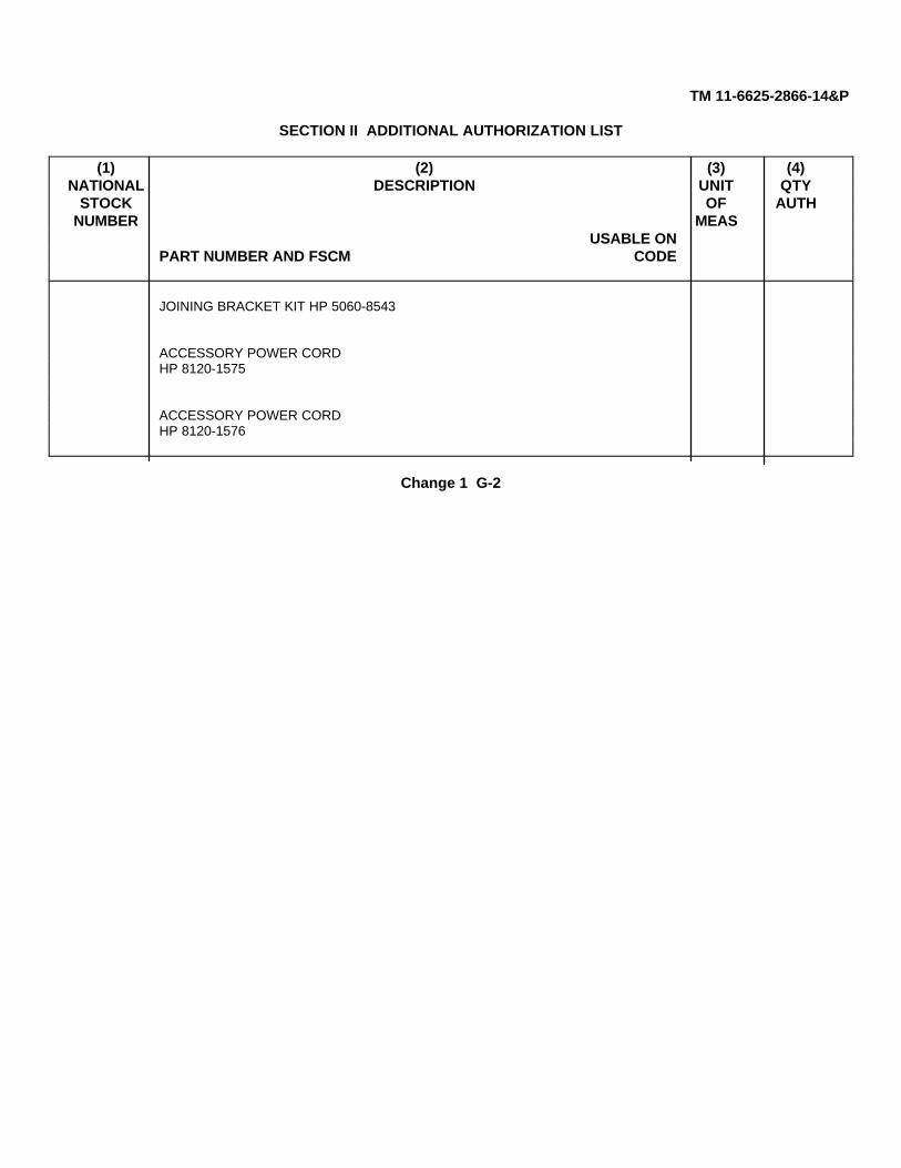
TM 11-6625-2866-14&P
SECTION II ADDITIONAL AUTHORIZATION LIST
(1) (2) (3) (4)NATIONAL DESCRIPTION UNIT QTY
STOCK OF AUTHNUMBER MEAS
USABLE ONPART NUMBER AND FSCM CODE
JOINING BRACKET KIT HP 5060-8543
ACCESSORY POWER CORDHP 8120-1575
ACCESSORY POWER CORDHP 8120-1576
Change 1 G-2
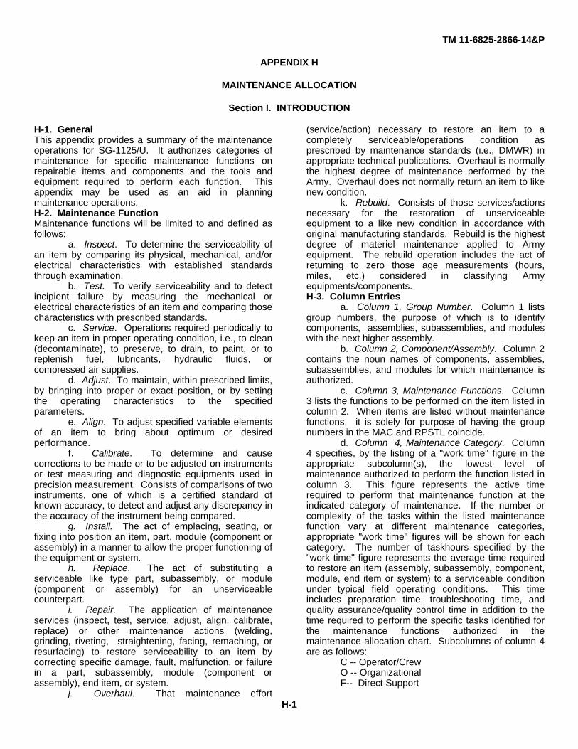
TM 11-6825-2866-14&P
APPENDIX H
MAINTENANCE ALLOCATION
Section I. INTRODUCTION
H-1. GeneralThis appendix provides a summary of the maintenanceoperations for SG-1125/U. It authorizes categories ofmaintenance for specific maintenance functions onrepairable items and components and the tools andequipment required to perform each function. Thisappendix may be used as an aid in planningmaintenance operations.H-2. Maintenance FunctionMaintenance functions will be limited to and defined asfollows:
a. Inspect. To determine the serviceability ofan item by comparing its physical, mechanical, and/orelectrical characteristics with established standardsthrough examination.
b. Test. To verify serviceability and to detectincipient failure by measuring the mechanical orelectrical characteristics of an item and comparing thosecharacteristics with prescribed standards.
c. Service. Operations required periodically tokeep an item in proper operating condition, i.e., to clean(decontaminate), to preserve, to drain, to paint, or toreplenish fuel, lubricants, hydraulic fluids, orcompressed air supplies.
d. Adjust. To maintain, within prescribed limits,by bringing into proper or exact position, or by settingthe operating characteristics to the specifiedparameters.
e. Align. To adjust specified variable elementsof an item to bring about optimum or desiredperformance.
f. Calibrate. To determine and causecorrections to be made or to be adjusted on instrumentsor test measuring and diagnostic equipments used inprecision measurement. Consists of comparisons of twoinstruments, one of which is a certified standard ofknown accuracy, to detect and adjust any discrepancy inthe accuracy of the instrument being compared.
g. Install. The act of emplacing, seating, orfixing into position an item, part, module (component orassembly) in a manner to allow the proper functioning ofthe equipment or system.
h. Replace. The act of substituting aserviceable like type part, subassembly, or module(component or assembly) for an unserviceablecounterpart.
i. Repair. The application of maintenanceservices (inspect, test, service, adjust, align, calibrate,replace) or other maintenance actions (welding,grinding, riveting, straightening, facing, remaching, orresurfacing) to restore serviceability to an item bycorrecting specific damage, fault, malfunction, or failurein a part, subassembly, module (component orassembly), end item, or system.
j. Overhaul. That maintenance effort
(service/action) necessary to restore an item to acompletely serviceable/operations condition asprescribed by maintenance standards (i.e., DMWR) inappropriate technical publications. Overhaul is normallythe highest degree of maintenance performed by theArmy. Overhaul does not normally return an item to likenew condition.
k. Rebuild. Consists of those services/actionsnecessary for the restoration of unserviceableequipment to a like new condition in accordance withoriginal manufacturing standards. Rebuild is the highestdegree of materiel maintenance applied to Armyequipment. The rebuild operation includes the act ofreturning to zero those age measurements (hours,miles, etc.) considered in classifying Armyequipments/components.H-3. Column Entries
a. Column 1, Group Number. Column 1 listsgroup numbers, the purpose of which is to identifycomponents, assemblies, subassemblies, and moduleswith the next higher assembly.
b. Column 2, Component/Assembly. Column 2contains the noun names of components, assemblies,subassemblies, and modules for which maintenance isauthorized.
c. Column 3, Maintenance Functions. Column3 lists the functions to be performed on the item listed incolumn 2. When items are listed without maintenancefunctions, it is solely for purpose of having the groupnumbers in the MAC and RPSTL coincide.
d. Column 4, Maintenance Category. Column4 specifies, by the listing of a "work time" figure in theappropriate subcolumn(s), the lowest level ofmaintenance authorized to perform the function listed incolumn 3. This figure represents the active timerequired to perform that maintenance function at theindicated category of maintenance. If the number orcomplexity of the tasks within the listed maintenancefunction vary at different maintenance categories,appropriate "work time" figures will be shown for eachcategory. The number of taskhours specified by the"work time" figure represents the average time requiredto restore an item (assembly, subassembly, component,module, end item or system) to a serviceable conditionunder typical field operating conditions. This timeincludes preparation time, troubleshooting time, andquality assurance/quality control time in addition to thetime required to perform the specific tasks identified forthe maintenance functions authorized in themaintenance allocation chart. Subcolumns of column 4are as follows:
C -- Operator/CrewO -- OrganizationalF-- Direct Support
H-1

TM 11-6625-2866-14&P
H-General SupportD-Depote. Column 5, Tools and Equipment. Column 5
specifies by code, those common tool sets (notindividual tools) and special tools, test, and supportequipment required to perform the designated function.
f. Column 6, Remarks. Column 6 contains analphabetic code which leads to the remark in section IV,Remarks, which is pertinent to the item opposite theparticular code.
H-4. Tool and Test Equipment Requirements(Sec III)
a. Tool or Test Equipment Reference Code.The numbers in this column coincide with the numbersused in the tools and equipment column of the MAC.The numbers indicate the applicable tool or testequipment for the maintenance functions.
b. Maintenance Category. The codes in thiscolumn indicate the maintenance category allocated the
tool or test equipment.c. Nomenclature. This column lists the noun
name and nomenclature of the tools and test equipmentrequired to perform the maintenance functions.
d. National/NATO Stock Number. This columnlists the National/NATO stock number of the specifictool or test equipment.
e. Tool Number. This column lists themanufacturer's part number of the tool followed by theFederal Supply Code for manufacturers (5-digit) inparentheses.
H-5. Remarks (Sec IV)a. Reference Code. This code refers to the
appropriate item in section II, column 6.b. Remarks. This column provides the required
explanatory information necessary to clarify itemsappearing in section II.
(Next printed page is H-3)
H-2
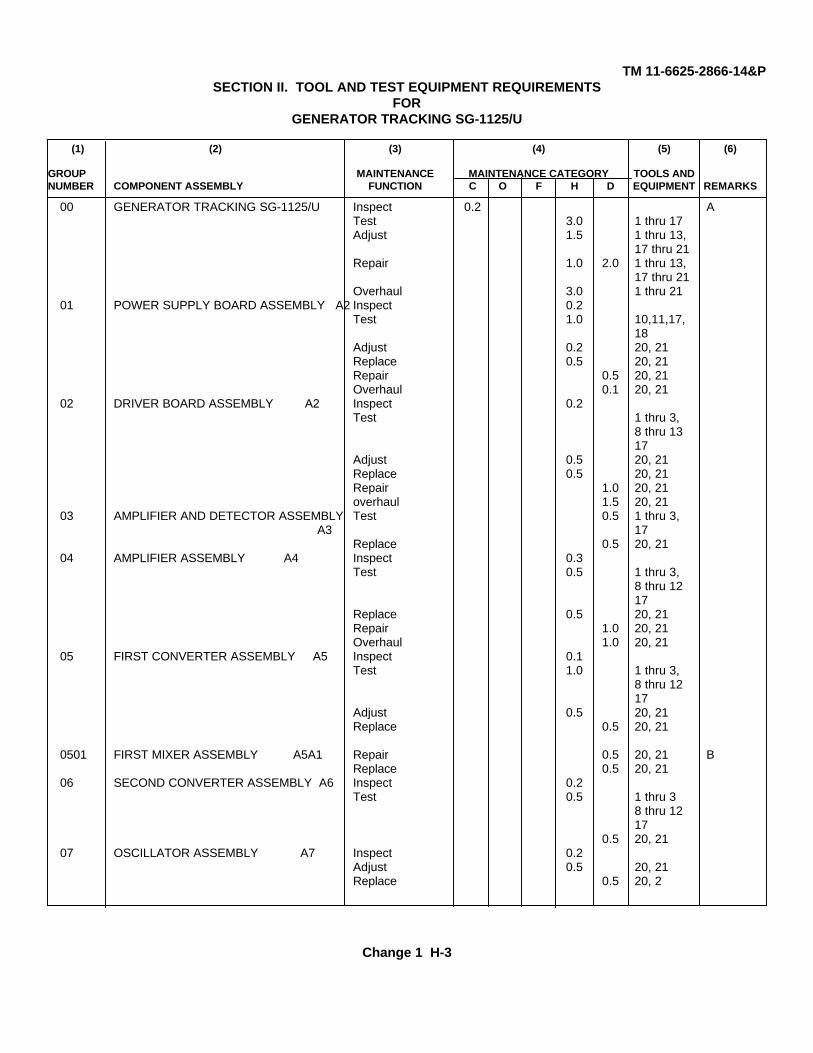
TM 11-6625-2866-14&PSECTION II. TOOL AND TEST EQUIPMENT REQUIREMENTS
FORGENERATOR TRACKING SG-1125/U
(1) (2) (3) (4) (5) (6)
GROUP MAINTENANCE MAINTENANCE CATEGORY TOOLS ANDNUMBER COMPONENT ASSEMBLY FUNCTION C O F H D EQUIPMENT REMARKS
00 GENERATOR TRACKING SG-1125/U Inspect 0.2 ATest 3.0 1 thru 17Adjust 1.5 1 thru 13,
17 thru 21Repair 1.0 2.0 1 thru 13,
17 thru 21Overhaul 3.0 1 thru 21
01 POWER SUPPLY BOARD ASSEMBLY A2 Inspect 0.2Test 1.0 10,11,17,
18Adjust 0.2 20, 21Replace 0.5 20, 21Repair 0.5 20, 21Overhaul 0.1 20, 21
02 DRIVER BOARD ASSEMBLY A2 Inspect 0.2Test 1 thru 3,
8 thru 1317
Adjust 0.5 20, 21Replace 0.5 20, 21Repair 1.0 20, 21overhaul 1.5 20, 21
03 AMPLIFIER AND DETECTOR ASSEMBLY Test 0.5 1 thru 3, A3 17
Replace 0.5 20, 2104 AMPLIFIER ASSEMBLY A4 Inspect 0.3
Test 0.5 1 thru 3,8 thru 1217
Replace 0.5 20, 21Repair 1.0 20, 21Overhaul 1.0 20, 21
05 FIRST CONVERTER ASSEMBLY A5 Inspect 0.1Test 1.0 1 thru 3,
8 thru 1217
Adjust 0.5 20, 21Replace 0.5 20, 21
0501 FIRST MIXER ASSEMBLY A5A1 Repair 0.5 20, 21 BReplace 0.5 20, 21
06 SECOND CONVERTER ASSEMBLY A6 Inspect 0.2Test 0.5 1 thru 3
8 thru 1217
0.5 20, 2107 OSCILLATOR ASSEMBLY A7 Inspect 0.2
Adjust 0.5 20, 21Replace 0.5 20, 2
Change 1 H-3
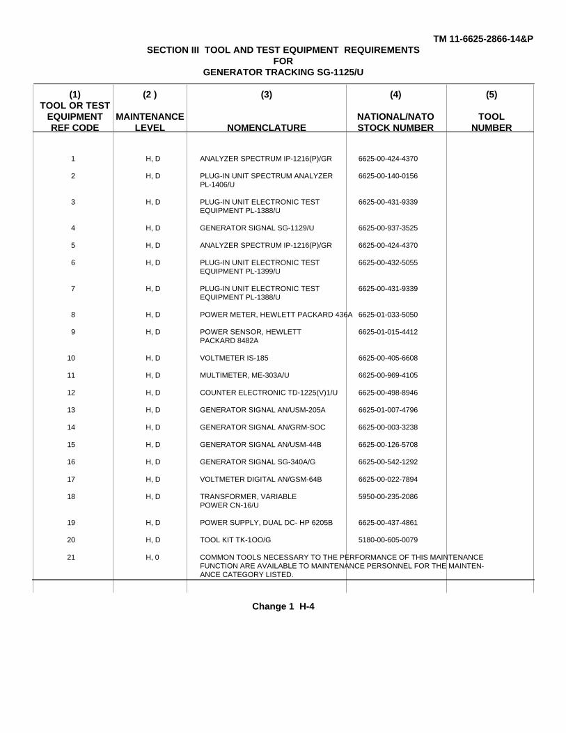
TM 11-6625-2866-14&PSECTION III TOOL AND TEST EQUIPMENT REQUIREMENTS
FORGENERATOR TRACKING SG-1125/U
(1) (2 ) (3) (4) (5)TOOL OR TEST
EQUIPMENT MAINTENANCE NATIONAL/NATO TOOLREF CODE LEVEL NOMENCLATURE STOCK NUMBER NUMBER
1 H, D ANALYZER SPECTRUM IP-1216(P)/GR 6625-00-424-4370
2 H, D PLUG-IN UNIT SPECTRUM ANALYZER 6625-00-140-0156PL-1406/U
3 H, D PLUG-IN UNIT ELECTRONIC TEST 6625-00-431-9339EQUIPMENT PL-1388/U
4 H, D GENERATOR SIGNAL SG-1129/U 6625-00-937-3525
5 H, D ANALYZER SPECTRUM IP-1216(P)/GR 6625-00-424-4370
6 H, D PLUG-IN UNIT ELECTRONIC TEST 6625-00-432-5055EQUIPMENT PL-1399/U
7 H, D PLUG-IN UNIT ELECTRONIC TEST 6625-00-431-9339EQUIPMENT PL-1388/U
8 H, D POWER METER, HEWLETT PACKARD 436A 6625-01-033-5050
9 H, D POWER SENSOR, HEWLETT 6625-01-015-4412PACKARD 8482A
10 H, D VOLTMETER IS-185 6625-00-405-6608
11 H, D MULTIMETER, ME-303A/U 6625-00-969-4105
12 H, D COUNTER ELECTRONIC TD-1225(V)1/U 6625-00-498-8946
13 H, D GENERATOR SIGNAL AN/USM-205A 6625-01-007-4796
14 H, D GENERATOR SIGNAL AN/GRM-SOC 6625-00-003-3238
15 H, D GENERATOR SIGNAL AN/USM-44B 6625-00-126-5708
16 H, D GENERATOR SIGNAL SG-340A/G 6625-00-542-1292
17 H, D VOLTMETER DIGITAL AN/GSM-64B 6625-00-022-7894
18 H, D TRANSFORMER, VARIABLE 5950-00-235-2086POWER CN-16/U
19 H, D POWER SUPPLY, DUAL DC- HP 6205B 6625-00-437-4861
20 H, D TOOL KIT TK-1OO/G 5180-00-605-0079
21 H, 0 COMMON TOOLS NECESSARY TO THE PERFORMANCE OF THIS MAINTENANCEFUNCTION ARE AVAILABLE TO MAINTENANCE PERSONNEL FOR THE MAINTEN-ANCE CATEGORY LISTED.
Change 1 H-4
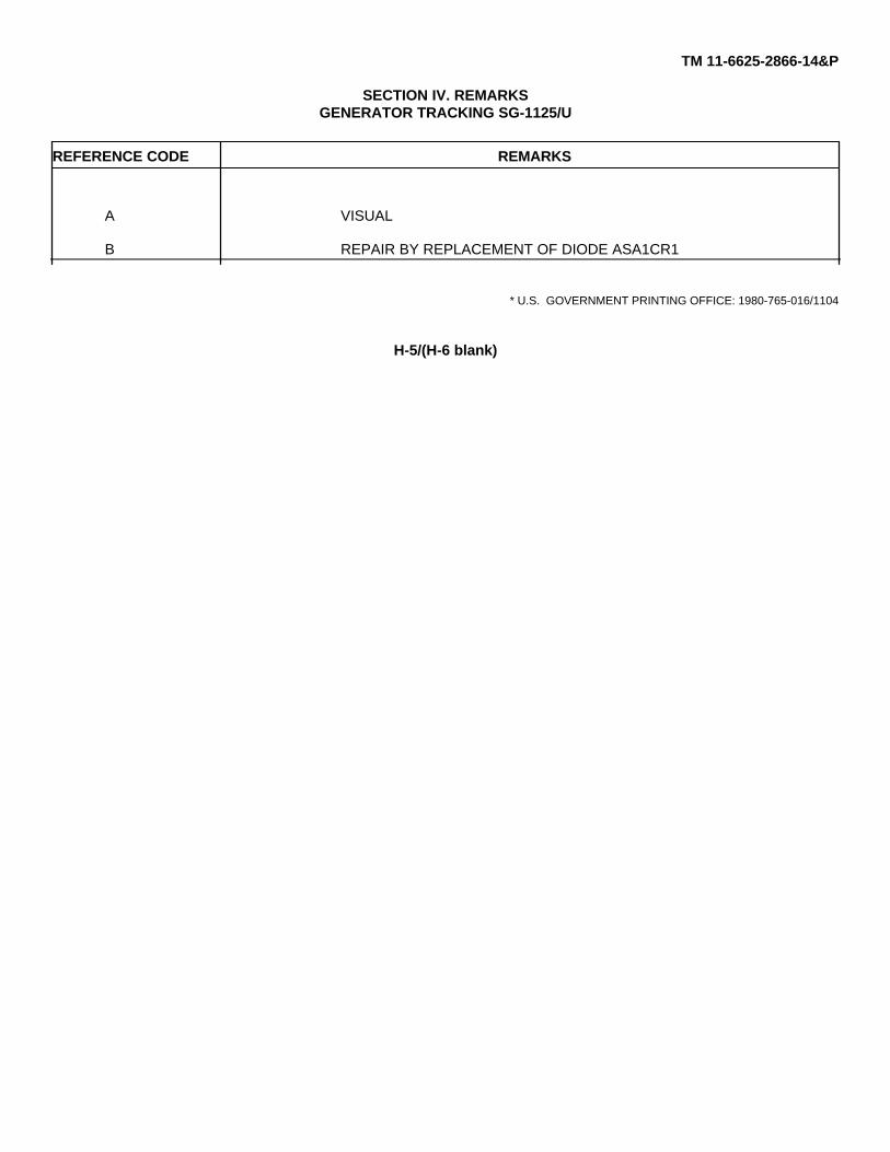
TM 11-6625-2866-14&P
SECTION IV. REMARKSGENERATOR TRACKING SG-1125/U
REFERENCE CODE REMARKS
A VISUAL
B REPAIR BY REPLACEMENT OF DIODE ASA1CR1
* U.S. GOVERNMENT PRINTING OFFICE: 1980-765-016/1104
H-5/(H-6 blank)

TM 11-6625-2866-14&P
APPENDIX I
REPAIR PARTS AND SPECIAL TOOLS LIST
Refer to Section VI, Replaceable Parts, for all maintenance parts.
I-1
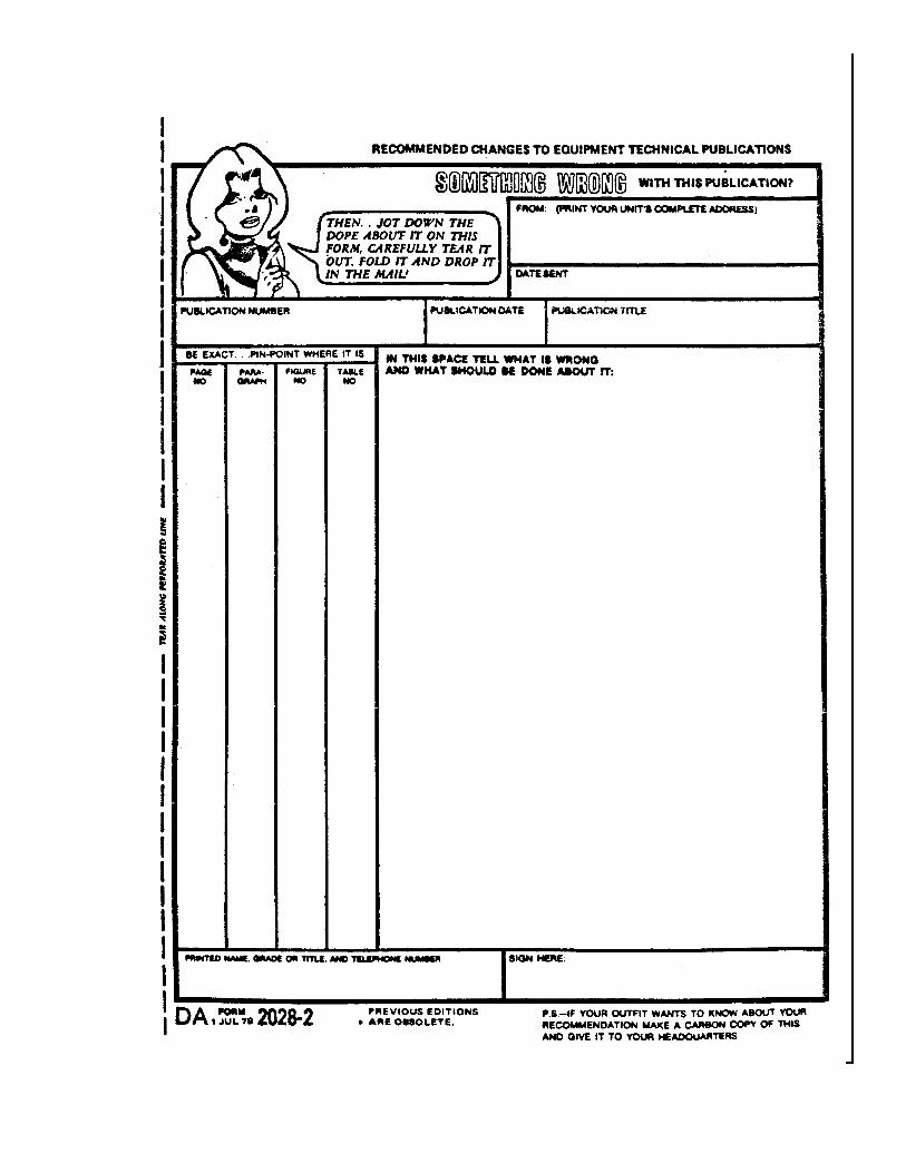

PIN 044822-001