Embed Size (px)
Citation preview
PAGE 1-3
PAGE 2-1
PAGE 2-16
PAGE 2-21
PAGE 3-2
T M 1 1 - 5 8 2 0 - 5 2 0 - 1 0
O P E R A T O R ' S M A N U A L
This copy is a reprint which includes current
pages from Change 1.
R A D I O S E T S A N / G R C - 1 0 6( N S N 5 8 2 0 - 0 0 - 4 0 2 - 2 2 6 3 )
A N / G R C - 1 0 6 A( N S N 5 8 2 0 - 0 0 2 2 3 - 7 5 4 8 )
H E A D Q U A R T E R S , D E P A R T M E N T O F T H E A R M Y
2 8 M A Y 1 9 8 4

T M 1 1 - 5 8 2 0 - 5 2 0 - 1 0
DANGEROUS VOLTAGES EXIST IN THIS EQUIPMENT
Voltages as high as 128 volts ac, 3,000 volts dc, and 10,000 volts RF are used in the operation of Amplifier, Radio Frequency AM-3349/GRC-106.
DANGEROUS VOLTAGES EXIST AT THE AM-3349/GRC-106 50-OHM LINE AND WHIP ANTENNA CONNECTORS
Be careful when working around the antenna or antenna connectors. Radio-frequency voltages as high as 10,000 volts exist at these points. Operatorand maintenance personnel should be familiar with the requirements ofTB SIG 291 before attempting installation or operation of Radio SetAN/GRC-106(*).
DEATH ON CONTACT
May result if operating personnel fail to observe safety precautions andfail to follow requirements of TB SIG 291.
DON’T TAKE CHANCES
WARNING
Adequate vent i lat ion should be provided whi le using T R I C H L O R O T R I F L U O R O -ETHANE. Prolonged breathing of vapor should be avoided. The solvent should
not be used near heat or open flame; the products of decomposition are toxic
and i r r i ta t i ng . S ince TR ICHLOROTR I F LUOROETHANE d i s so lves na tu ra l o i l s , p ro-
longed con tac t w i th sk in shou ld be avo ided . When necessa ry , u se g loves
which the solvent cannot penetrate. I f the solvent is taken internal ly, consult a
phys ic ian immedia te ly .
TM 11-5820-529-10C 1
Change
No. 1
HEADQUARTERSDEPARTMENT OF THE ARMY
Washington, DC, 15 May 1989
OPERATOR’S MANUAL
RADIO SETSAN/GRC-106
(NSN 5820-00-402-2263)AN/GRC-106A
(NSN 5820-00-223-7548)
TM 11-5820-520-10, 28 May 1984 is changed as follows:
1. Remove old pages and insert new pages as indicated below. New or changedmaterial is indicated by a vertical bar in the margin of the page. Revised illustrationsare indicated by a miniature pointing hand adjacent to the changed area.
Remove pages Insert pages
a and c . . . . . . . . . . . . . . . . . . . . . . . . . . . . . . . a through dband d . . . . . . . . . . . . . . . . . . . . . . . . . . . . . . . .Nonei and ii . . . . . . . . . . . . . . . . . . . . . . . . . . . . . . . . i and ii1-1 through 1-4 . . . . . . . . . . . . . . . . . . . . . . . . .1-1 through 1-41-7 and 1-8 . . . . . . . . . . . . . . . . . . . . . . . . . . . . 1-7 and 1-82-9 and 2-10 . . . . . . . . . . . . . . . . . . . . . . . . . . . 2-9 and 2-102-15 through 2-20 . . . . . . . . . . . . . . . . . . . . . . . 2-15 through 2-202-23 through 2-26 . . . . . . . . . . . . . . . . . . . . . . . 2-23 through 2-262-29 and 2-30 . . . . . . . . . . . . . . . . . . . . . . . . . . 2-29 and 2-302-33 through 2-40 . . . . . . . . . . . . . . . . . . . . . . . 2-33 through 2-402-45 and 2-46 . . . . . . . . . . . . . . . . . . . . . . . . . . 2-45 and 2-463-3 and 3-4 . . . . . . . . . . . . . . . . . . . . . . . . . . . . 3-3 and 3-4A-1 and A-2 . . . . . . . . . . . . . . . . . . . . . . . . . . . A-1 and A-2B-5 through B-7/(B-8 blank) . . . . . . . . . . . . . B-5 through B-7/(B-8 blank)
2. File this change sheet in front of the publication for reference purposes.
Distribution authorized to the Department of Defense and DOD contractors onlyfor official use or for administration or operational purposes. This determinationwas made on 9 February 1989. Other requests for this document will bereferred to Commander, US Army Communications-Electronics Command andFort Monmouth, ATTN: AMSEL-LC-ME-P, Fort Monmouth, NJ 07703-5000.
DESTRUCTION NOTICE – Destroy by any method that will prevent disclosure ofcontents or reconstruction of the document.
TM11-5820-520-10
WARNING
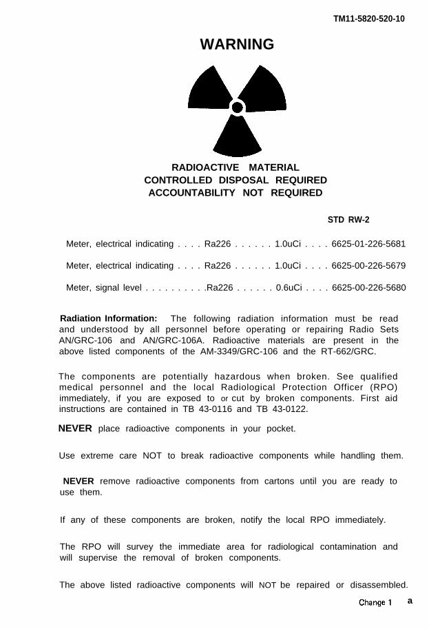
RADIOACTIVE MATERIALCONTROLLED DISPOSAL REQUIREDACCOUNTABILITY NOT REQUIRED
STD RW-2
Meter, electrical indicating . . . . Ra226 . . . . . . 1.0uCi . . . . 6625-01-226-5681
Meter, electrical indicating . . . . Ra226 . . . . . . 1.0uCi . . . . 6625-00-226-5679
Meter, signal level . . . . . . . . . .Ra226 . . . . . . 0.6uCi . . . . 6625-00-226-5680
Radiation Information: The following radiation information must be readand understood by all personnel before operating or repairing Radio SetsAN/GRC-106 and AN/GRC-106A. Radioactive materials are present in theabove listed components of the AM-3349/GRC-106 and the RT-662/GRC.
The components are potentially hazardous when broken. See qualifiedmedical personnel and the local Radiological Protection Officer (RPO)immediately, if you are exposed to or cut by broken components. First aidinstructions are contained in TB 43-0116 and TB 43-0122.
NEVER place radioactive components in your pocket.
Use extreme care NOT to break radioactive components while handling them.
NEVER remove radioactive components from cartons until you are ready touse them.
If any of these components are broken, notify the local RPO immediately.
The RPO will survey the immediate area for radiological contamination andwill supervise the removal of broken components.
The above listed radioactive components will NOT be repaired or disassembled.
a
TM11-5820-520-10
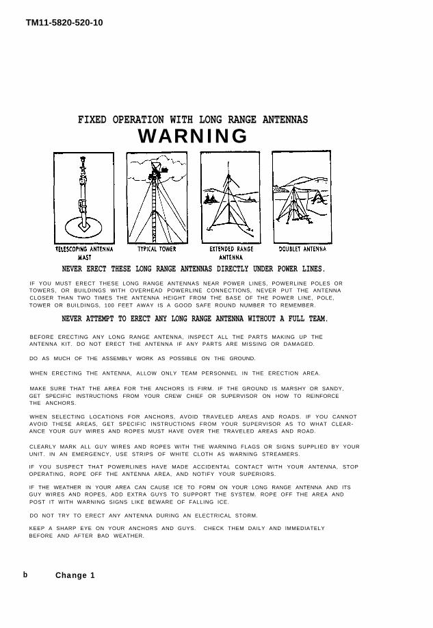
FIXED OPERATION WITH LONG RANGE ANTENNASWARNING
NEVER ERECT THESE LONG RANGE ANTENNAS DIRECTLY UNDER POWER LINES.IF YOU MUST ERECT THESE LONG RANGE ANTENNAS NEAR POWER LINES, POWERLINE POLES ORTOWERS, OR BUILDINGS WITH OVERHEAD POWERLINE CONNECTIONS, NEVER PUT THE ANTENNACLOSER THAN TWO TIMES THE ANTENNA HEIGHT FROM THE BASE OF THE POWER LINE, POLE,TOWER OR BUILDINGS, 100 FEET AWAY IS A GOOD SAFE ROUND NUMBER TO REMEMBER.
NEVER ATTEMPT TO ERECT ANY LONG RANGE ANTENNA WITHOUT A FULL TEAM.
BEFORE ERECTING ANY LONG RANGE ANTENNA, INSPECT ALL THE PARTS MAKING UP THEANTENNA KIT. DO NOT ERECT THE ANTENNA IF ANY PARTS ARE MISSING OR DAMAGED.
DO AS MUCH OF THE ASSEMBLY WORK AS POSSIBLE ON THE GROUND.
WHEN ERECTING THE ANTENNA, ALLOW ONLY TEAM PERSONNEL IN THE ERECTION AREA.
MAKE SURE THAT THE AREA FOR THE ANCHORS IS FIRM. IF THE GROUND IS MARSHY OR SANDY,GET SPECIFIC INSTRUCTIONS FROM YOUR CREW CHIEF OR SUPERVISOR ON HOW TO REINFORCETHE ANCHORS.
WHEN SELECTING LOCATIONS FOR ANCHORS, AVOID TRAVELED AREAS AND ROADS. IF YOU CANNOTAVOID THESE AREAS, GET SPECIFIC INSTRUCTIONS FROM YOUR SUPERVISOR AS TO WHAT CLEAR-ANCE YOUR GUY WlRES AND ROPES MUST HAVE OVER THE TRAVELED AREAS AND ROAD.
CLEARLY MARK ALL GUY WIRES AND ROPES WITH THE WARNING FLAGS OR SIGNS SUPPLIED BY YOURUNIT. IN AN EMERGENCY, USE STRIPS OF WHITE CLOTH AS WARNING STREAMERS.
IF YOU SUSPECT THAT POWERLINES HAVE MADE ACCIDENTAL CONTACT WITH YOUR ANTENNA, STOPOPERATING, ROPE OFF THE ANTENNA AREA, AND NOTIFY YOUR SUPERIORS.
IF THE WEATHER IN YOUR AREA CAN CAUSE ICE TO FORM ON YOUR LONG RANGE ANTENNA AND ITSGUY WIRES AND ROPES, ADD EXTRA GUYS TO SUPPORT THE SYSTEM. ROPE OFF THE AREA AND
POST IT WITH WARNING SIGNS LIKE BEWARE OF FALLING ICE.
DO NOT TRY TO ERECT ANY ANTENNA DURING AN ELECTRICAL STORM.
KEEP A SHARP EYE ON YOUR ANCHORS AND GUYS. CHECK THEM DAILY AND lMMEDIATELYBEFORE AND AFTER BAD WEATHER.
b Change 1
TM 11-5820-520-10
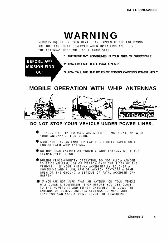
WARNINGS E R I O U S I N J U R Y O R E V E N D E A T H C A N H A P P E N I F T H E F O L L O W I N GA R E N O T C A R E F U L L Y O B S E R V E D W H E N I N S T A L L I N G A N D U S I N G
T H E A N T E N N A S U S E D W I T H Y O U R R A D I O S E T S .
1. ARE THERE ANY
2. HOW HIGH ARE
3. HOW TALL ARE
POWERLINES IN YOUR AREA OF OPERATION ?
THESE POWERLINES ?
THE POLES OR TOWERS CARRYING POWERLINES ?
MOBILE OPERATION WITH WHIP ANTENNAS
DO NOT STOP YOUR VEHICLE UNDER POWER LINES.
●
●
●
●
I F P O S S I B L E , T R Y T O M A I N T A I N M O B I L E C O M M U N I C A T I O N S W I T HY O U R A N T E N N A ( S ) T I E D D O W N .
M A K E S U R E A N A N T E N N A T I P C A P I S S E C U R E L Y T A P E D O N T H EE N D O F E A C H W H I P A N T E N N A .
D O N O T L E A N A G A I N S T O R T O U C H A W H I P A N T E N N A W H I L E T H ET R A N S M I T T E R I S O N .
D U R I N G C R O S S - C O U N T R Y O P E R A T I O N , D O N O T A L L O W A N Y O N ET O S T I C K A N A R M , L E G O R W E A P O N O V E R T H E S I D E S O F T H EV E H I C L E . I F Y O U R A N T E N N A A C C I D E N T A L L Y T O U C H E S APOWERLINE AND A LEG, ARM OR WEAPON CONTACTS A DAMPB U S H O R T H E G R O U N D , A S E R I O U S O R F A T A L A C C I D E N T C A NHAPPEN.
● IF YOU ARE NOT SURE THAT AN ANTENNA ON YOUR VEHICLEW I L L C L E A R A P O W E R L I N E , S T O P B E F O R E Y O U G E T C L O S ET O T H E P O W E R L I N E A N D E I T H E R C A R E F U L L Y T I E D O W N T H EANTENNA OR REMOVE ANTENNA SECTIONS TO MAKE SURET H A T Y O U C A N S A F E L Y D R I V E U N D E R T H E P O W E R L I N E .
Change 1 c

TM11-5820-520-10
SAFETY STEPS TO FOLLOW IF SOMEONEIS THE VICTIM OF ELECTRICAL SHOCK
DO NOT TRY TO PULL OR GRAB THE INDIVIDUAL
IF POSSIBLE, TURN OFF THE ELECTRICAL POWER
IF YOU CANNOT TURN OFF THE ELECTRICAL POWER,PULL, PUSH, OR LIFT THE PERSON TO SAFETY USINGA DRY WOODEN POLE OR A DRY ROPE OR SOME OTHERINSULATING MATERIAL
SEND FOR HELP AS SOON AS POSSIBLE
AFTER THE INJURED PERSON IS FREE OF CONTACTWITH THE SOURCE OF ELECTRICAL SHOCK, MOVE THEPERSON A SHORT DISTANCE AWAY AND IMMEDIATELYSTART ARTIFICIAL RESUSCITATION
d Change 1

Technical Manual
*TM11-5820-520-10
No. 11-5820-520-10
HEADQUARTERSDEPARTMENT OF THE ARMY
Washington, DC, 28 May 1984
OPERATOR’S MANUALRADIO SETS
AN/GRC-106 (NSN 5820-00-402-2263)AND
AN/GRC-106A (NSN 5820-00-223-7548)
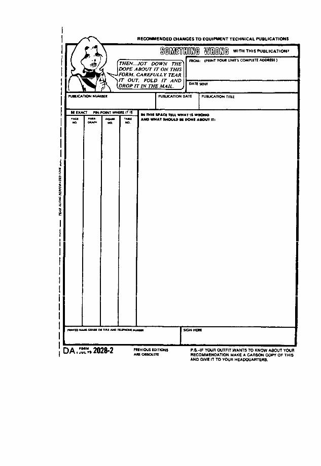
REPORTING ERRORS AND RECOMMENDING IMPROVEMENTS
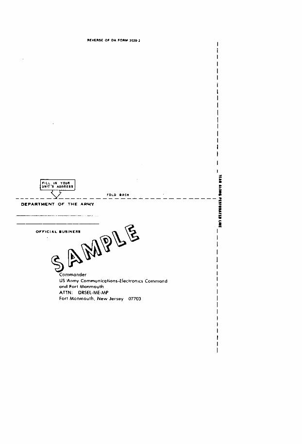
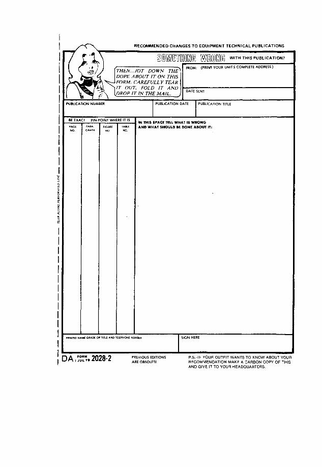
You can help improve this manual. If you find any mistakes or if youknow of a way to improve the procedures, please let us know. Mail yourletter or DA Form 2028 (Recommended Changes to Publications and BlankForms) direct to: Commander, US Army Communications-ElectronicsCommand and Fort Monmouth, ATTN: AMSEL-LC-ME-PS, Fort Monmouth,New Jersey 07703-5000. In either case, a reply will be furnished directto you.
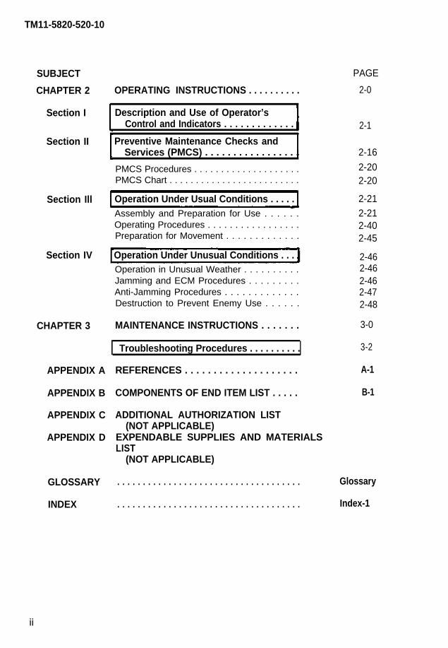
SUBJECT PAGE
CHAPTER 1 INTRODUCTION . . . . . . . . . . . . . . . . . . . . . . . . . . . . . . . . . . . . . . . 1-1
Section I General Information . . . . . . . . . . . . . . . . . . . . . . . . . . . . . . . . 1-1Scope . . . . . . . . . . . . . . . . . . . . . . . . . . . . . . . . . . . . . . . . . . . . . . . . . . . . . . . . . . . . . . . .1-1Consolidated Index of Army Publications
and Blank Forms . . . . . . . . . . . . . . . . . . . . . . . . . . . . . . . . . . . . . . . . . . . . . 1-1Maintenance Forms, Records and Reports . . . . . . . . . . . . . . . . . . 1-1Administrative Storage . . . . . . . . . . . . . . . . . . . . . . . . . . . . . . . . .1-1Destruction of Army Electronics Materiel . . . . . . . . . . . . . . . . . 1-1Reporting Equipment Improvement
Recommendations (EIR) . . . . . . . . . . . . . . . . . . . . . . . . . . . . . . . . . 1-1Nomenclature Cross Reference List . . . . . . . . . . . . . . . . . . . . . 1-2List of Abbreviations . . . . . . . . . . . . . . . . . . . . . . . . . . . . . . . . . . . .1-2Hand Receipt . . . . . . . . . . . . . . . . . . . . . . . . . . . . . . . . . . . . . . . . . . . . . . . . . . . . . . . .1-2
Section II Equipment Description . . . . . . . . . . . . . . . . . . . . . . . . . . . 1-3
Section Ill
Equipment Purpose, Capabilities and Features . . . . . . . . . . . . 1-3Description of Major Components . . . . . . . . . . . . . . . . . . . . . . . 1-3Antenna Description . . . . . . . . . . . . . . . . . . . . . . . . . . . . . . . . . . . . . . .1-4Differences Between Models . . . . . . . . . . . . . . . . . . . . . . . . . . . . .1-5Performance Data . . . . . . . . . . . . . . . . . . . . . . . . . . . . . . . . . . . . . . . . . . . . . . . . 1 -7
Technical Principles of Operation . . . . . . . . . . . . . . . . . . . . 1-9
*This manual supersedes TM 11-5820-520-10, 23 November 1982.
i
TM11-5820-520-10
SUBJECT
CHAPTER 2
Section I
PAGE
2-0OPERATING INSTRUCTIONS . . . . . . . . . .
Description and Use of Operator’sControl and Indicators . . . . . . . . . . . . .
Preventive Maintenance Checks and
2-1
Section IIServices (PMCS) . . . . . . . . . . . . . . . . . 2-16
2-202-20
2-212-212-402-45
PMCS Procedures . . . . . . . . . . . . . . . . . . . .PMCS Chart . . . . . . . . . . . . . . . . . . . . . . . . .
Section Ill Operation Under Usual Conditions . . . . .Assembly and Preparation for Use . . . . . .Operating Procedures . . . . . . . . . . . . . . . . .Preparation for Movement . . . . . . . . . . . . .
Operation Under Unusual Conditions . . . .Section IV 2-462-462-462-47
Operation in Unusual Weather . . . . . . . . . .Jamming and ECM Procedures . . . . . . . . .Anti-Jamming Procedures . . . . . . . . . . . . .Destruction to Prevent Enemy Use . . . . . . 2-48
3-0CHAPTER 3 MAINTENANCE INSTRUCTIONS . . . . . . .
3-2Troubleshooting Procedures . . . . . . . . . .
REFERENCES . . . . . . . . . . . . . . . . . . . .APPENDIX A
APPENDIX B
APPENDIX C
APPENDIX D
A-1
COMPONENTS OF END ITEM LIST . . . . . B-1
ADDITIONAL AUTHORIZATION LIST(NOT APPLICABLE)
EXPENDABLE SUPPLIES AND MATERIALSLIST
(NOT APPLICABLE)
Glossary
Index-1
GLOSSARY
INDEX
. . . . . . . . . . . . . . . . . . . . . . . . . . . . . . . . . . . .
. . . . . . . . . . . . . . . . . . . . . . . . . . . . . . . . . . . .
ii
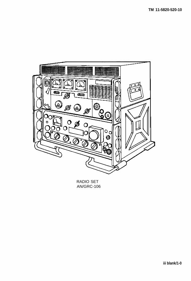
TM 11-5820-520-10
RADIO SETAN/GRC-106
iii blank/1-0

T M 1 1 - 5 8 2 0 - 5 2 0 - 1 0
CHAPTER 1
INTRODUCTION
Section 1. GENERAL
1-1. SCOPE
This manual i s for your use in operat ing Radio Sets AN/GRC-106 and AN/GRC-106A. I t
gives detailed operating instructions, and will tell you how to set up and maintain the
e q u i p m e n t . A N G R C - 1 0 6 ( * ) w i l l d e s i g n a t e b o t h t h e A N / G R C - 1 0 6 a n d A N - G R C - 1 0 6 A .
1-2. CONSOLIDATED INDEX OF ARMY PUBLICATIONS AND BLANK FORMS
Refer to the latest issue of DA Pam 25-30 to determine whether there are new editions,
changes or addit ional publ icat ions pertain ing to the equipment.
1-3. MAINTENANCE FORMS, RECORDS, AND REPORTS
a . R e p o r t s o f M u i n t e n a n c e a n d U n s a t i s f a c t o r y E q u i p m e n t . D e p a r t m e n t o f t h e
A r m y f o r m s a n d p r o c e d u r e s u s e d f o r e q u i p m e n t m a i n t e n a n c e w i l l b e t h o s e p r e s c r i b e d
by DA Pam 738-750 as contained in Maintenance Management Update.
h. Reporting of Item and Packaging Discrepancies. Fill out and forward SF 364
(Report of Discrepancy (ROD)) as prescribed in AR 735-11-2/DLAR 4140.55/SECNAVINST
4355 .18 AFR 400 -54/MCO 4430 .3J .
c . T r a n s p o r t a t i o n D i s c r e p a n c y R e p o r t ( T D R ) ( S F 3 6 1 ) . F i l l o u t a n d f o r w a r d
T r a n s p o r t a t i o n D i s c r e p a n c y R e p o r t ( T D R ) ( S F 3 6 1 ) a s p r e s c r i b e d i n A R 5 5 - 3 8 /
NAVSUP INST 4610 .33C/AFR 75 -18/MCO P4610 .19D/DLAR 4500 .15 .
1 - 4 . A D M I N I S T R A T I V E S T O R A G E
Administ rat ive storage of equipment i ssued to and used by Army act iv i t ies wi l l have
preventive maintenance performed in accordance with the PMCS charts before storing.
W h e n r e m o v i n g t h e e q u i p m e n t f r o m a d m i n i s t r a t i v e s t o r a g e t h e P M C S s h o u l d b e
performed to assure operat ional readiness.
1-5. DESTRUCTION OF ARMY ELECTRONICS MATERIEL
Destruction of Army electronics materiel to prevent enemy use shall be in accordance
with TM 750-244-2.
1-6. REPORTING EQUIPMENT IMPROVEMENT RECOMMENDATIONS (E IR)
I f your AN/GRC-106 needs improvement, let US know. Send us an EIR. You, the user,
are the only one who can tell us what you don’t like about your equipment. Let US k n o w
why you don’t l ike the des ign or performance. Put i t on an SF 368 (product Qual i ty
D e f i c i e n c y R e p o r t ) , M a i l i t t o : C o m m a n d e r , U S A r m y C o m m u n i c a t i o n s - E l e c t r o n i c sCommand and Fort Monmouth, ATTN: AMSEL-PA-MA-D, Fort Monmouth, New Jersey
07703-5000. We’l l send you a reply.
Change 1 1-1
TM 11-5820-520-10
1 - 7 . N O M E N C L A T U R E C R O S S - R E F E R E N C E L I S T
Common names wi l l be used when the major components of the Radio Set arem e n t i o n e d i n t h i s m a n u a l .
C O M M O N N A M E
Radio Set . . . . . . . . . . . . . . . . . . . . . . . . . . . . . .RT . . . . . . . . . . . . . . . . . . . . . . . . . . . . . . . . . . .
Amplifier . . . . . . . . . . . . . . . . . . . . . . . . . . . . .
RT mount . . . . . . . . . . . . . . . . . . . . . . . . . . . . .Telegraph Key . . . . . . . . . . . . . . . . . . . . . . . . .Loudspeaker . . . . . . . . . . . . . . . . . . . . . . . . . . .Headset . . . . . . . . . . . . . . . . . . . . . . . . . . . . . . .Handset . . . . . . . . . . . . . . . . . . . . . . . . . . . . . . .Microphone . . . . . . . . . . . . . . . . . . . . . . . . . . .Antenna . . . . . . . . . . . . . . . . . . . . . . . . . . . . . .
N O M E N C L A T U R E
A N / G R C - 1 0 6 ( * )R e c e i v e r - T r a n s m i t t e r , R a d i o
RT -662/GRC o r RT -834/GRCAmpl i f i e r , Rad io F requency
A M - 3 3 4 9 / G R C - 1 0 6M o u n t i n g M T - 3 1 4 0 / G R C - 1 0 6K e y , T e l e g r a p h K Y - 1 1 6 / UD y n a m i c L o u d s p e a k e r L S - 1 6 6 / UH e a d s e t , E l e c t r i c a l H - 2 2 7 / UH a n d s e t , H - 3 3 / ( * ) P TM i c r o p h o n e , C a r b o n M - 2 9 B / UA n t e n n a G r o u p A N / G R A - 5 0
N O T E
If either the RT or Amplifier requires repair turn in both components
1 - 8 . L I S T O F A B B R E V I A T I O N S
A b b r e v i a t i o n s a r e s p e l l e d o u t t h e f i r s t t i m e t h e y a p p e a r i n t h i s m a n u a l . A I i s t o f
a b b r e v i a t i o n s c o m m o n l y u s e d i n t h i s m a n u a l i s p r o v i d e d b e l o w .
Amplitude modulation . . . . . . . . . . . . . . . . . . . . . . . . . . . . . . . . . . . . AM
Antenna . . . . . . . . . . . . . . . . . . . . . . . . . . . . . . . . . . . . . . . . . . . . . . . . .ANT
Beat-frequency oscillator . . . . . . . . . . . . . . . . . . . . . . . . . . . . . . . . . . . BFO
Continuous wave . . . . . . . . . . . . . . . . . . . . . . . . . . . . . . . . . . . . . . . . . . CW
Frequency . . . . . . . . . . . . . . . . . . . . . . . . . . . . . . . . . . . . . . . . . . . . . . . . FREQ
Frequency-shift-keyed . . . . . . . . . . . . . . . . . . . . . . . . . . . . . . . . . . . . . FSK
Ground . . . . . . . . . . . . . . . . . . . . . . . . . . . . . . . . . . . . . . . . . . . . . . . . . . GRD
High voltage . . . . . . . . . . . . . . . . . . . . . . . . . . . . . . . . . . . . . . . . . . . . . . HV
Intermediate frequency . . . . . . . . . . . . . . . . . . . . . . . . . . . . . . . . . . . . . IF
Kilohertz . . . . . . . . . . . . . . . . . . . . . . . . . . . . . . . . . . . . . . . . . . . . . . . . . kHz
Megahertz . . . . . . . . . . . . . . . . . . . . . . . . . . . . . . . . . . . . . . . . . . . . . . . . MHz
Narrow frequency-shift-keyed. . . . . . . . . . . . . . . . . . . . . . . . . . . . . . . NSK
Power . . . . . . . . . . . . . . . . . . . . . . . . . . . . . . . . . . . . . . . . . . . . . . . . . . . PWR
Primary . . . . . . . . . . . . . . . . . . . . . . . . . . . . . . . . . . . . . . . . . . . . . . . . . . PRIM
Receiver . . . . . . . . . . . . . . . . . . . . . . . . . . . . . . . . . . . . . . . . . . . . . . . . . RCVR
Single-sideband . . . . . . . . . . . . . . . . . . . . . . . . . . . . . . . . . . . . . . . . . ..SSB
Upper-sideband . . . . . . . . . . . . . . . . . . . . . . . . . . . . . . . . . . . . . . . . . . . usb
1 - 9 . H A N D R E C E I P T
T h i s m a n u a l h a s a c o m p a n i o n d o c u m e n t w i t h a T M n u m b e r f o l l o w e d b y
" - H R " ( w h i c h s t a n d s f o r H a n d R e c e i p t ) . T M 1 1 - 5 8 2 0 - 5 2 0 - 1 0 - H R c o n s i s t s o f
p r e p r i n t e d h a n d r e c e i p t s ( D A F o r m 2 0 6 2 ) t h a t l i s t e n d i t e m r e l a t e d e q u i p -
m e n t ( i . e . , C O E l , B l l , a n d A A L ) y o u m u s t a c c o u n t f o r . A s a n a i d t o p r o p e r t y
a c c o u n t a b i l i t y , a d d i t i o n a l - H R m a n u a l s m a y b e r e q u i s i t i o n e d f r o m T h e U S
A r m y A d j u t a n t G e n e r a l P u b l i c a t i o n s C e n t e r , B a l t i m o r e , M D , i n a c c o r d a n c e
w i t h t h e p r o c e d u r e s i n C h a p t e r 3 , A R 3 1 0 - 2 , a n d D A P A M 3 1 0 - 1 0 .
1-2 Change 1
TM 11-5820-520-10
Section Il. EQUIPMENT DESCRIPTION
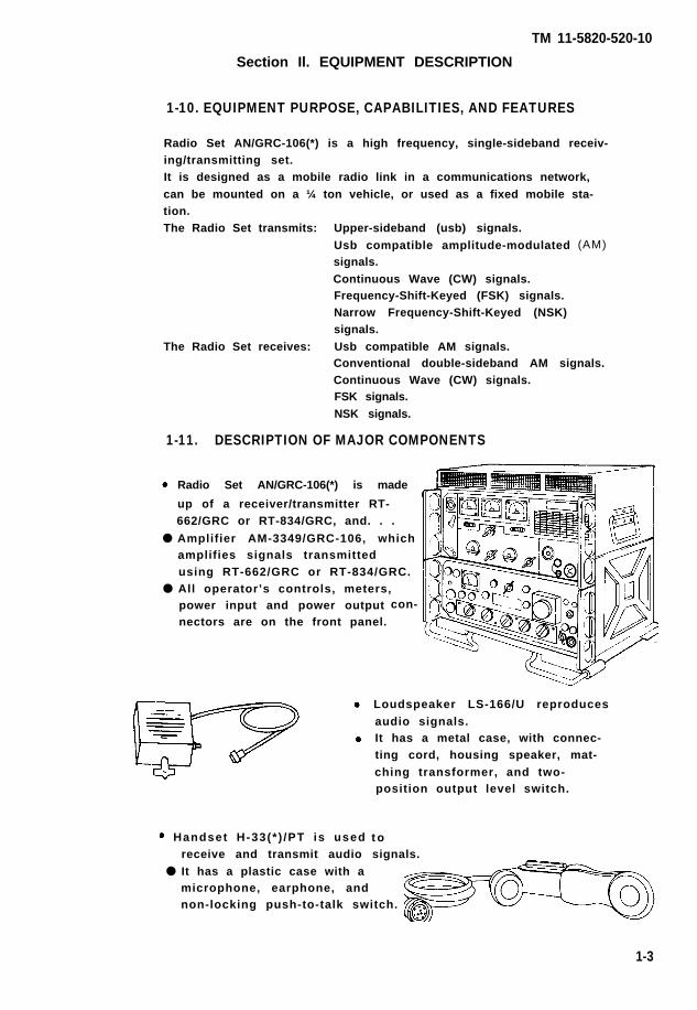
1-10. EQUIPMENT PURPOSE, CAPABILITIES, AND FEATURES
Radio Set AN/GRC-106(*) is a high frequency, single-sideband receiv-ing/transmitting set.It is designed as a mobile radio link in a communications network,can be mounted on a ¼ ton vehicle, or used as a fixed mobile sta-tion.The Radio Set transmits: Upper-sideband (usb) signals.
Usb compatible amplitude-modulatedsignals.Continuous Wave (CW) signals.Frequency-Shift-Keyed (FSK) signals.Narrow Frequency-Shift-Keyed (NSK)signals.
The Radio Set receives: Usb compatible AM signals.
(AM)
Conventional double-sideband AM signals.Continuous Wave (CW) signals.FSK signals.NSK signals.
1-11. DESCRIPTION OF MAJOR COMPONENTS
Radio Set AN/GRC-106(*) is made
up of a receiver/transmitter RT-662/GRC or RT-834/GRC, and. . .
● Amplifier AM-3349/GRC-106, whichamplifies signals transmittedusing RT-662/GRC or RT-834/GRC.
● All operator’s controls, meters,power input and power outputnectors are on the front panel.
con-
Handset H-33(* ) /PT is used
Loudspeaker LS-166/U reproducesaudio signals.It has a metal case, with connec-ting cord, housing speaker, mat-ching transformer, and two-position output level switch.
t oreceive and transmit audio signals.
● It has a plastic case with amicrophone, earphone, andnon-locking push-to-talk switch.
1-3
TM11-5820-520-10
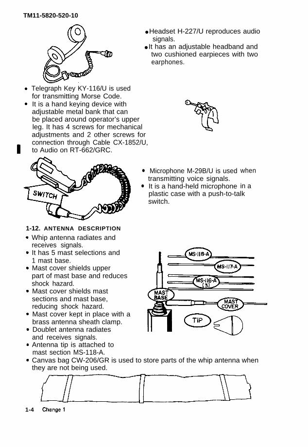
Telegraph Key KY-116/U is usedfor transmitting Morse Code.It is a hand keying device withadjustable metal bank that canbe placed around operator’s upperleg. It has 4 screws for mechanicaladjustments and 2 other screws forconnection through Cable CX-1852/U,to Audio on RT-662/GRC.
●
●
● Headset H-227/U reproduces audiosignals.
● It has an adjustable headband andtwo cushioned earpieces with twoearphones.
1-12. ANTENNA DESCRIPTION
Whip antenna radiates andreceives signals.It has 5 mast selections and1 mast base.Mast cover shields upperpart of mast base and reducesshock hazard.Mast cover shields mastsections and mast base,reducing shock hazard.Mast cover kept in place with abrass antenna sheath clamp.Doublet antenna radiatesand receives signals.Antenna tip is attached tomast section MS-118-A.
Microphone M-29B/U is usedtransmitting voice signals.It is a hand-held microphone
when
in aplastic case with a push-to-talkswitch.
Canvas bag CW-206/GR is used to store parts of the whip antenna whenthey are not being used.
1-4
1-5
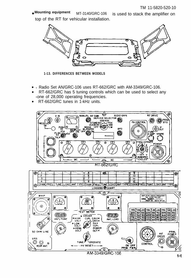
TM 11-5820-520-10● Mounting equipment
top of the RT for vehicular installation.MT-3140/GRC-106 is used to stack the amplifier on
1-13. DIFFERENCES BETWEEN MODELS
Radio Set AN/GRC-106 uses RT-662/GRC with AM-3349/GRC-106. RT-662/GRC has 5 tuning controls which can be used to select anyone of 28,000 operating frequencies. RT-662/GRC tunes in 1-kHz units.

TM 11-5820-520-10
Radio Set AN/GRC-106A uses RT-834/GRC with AM-3349/GRC-106. RT-834/GC has 6 tuning controls which can be used to select anyone of 280,000 operating frequencies.
RT-834/GRC tunes in 100-Hz units.
RT-834/GRC
AM-3349/GRC-106
1-6
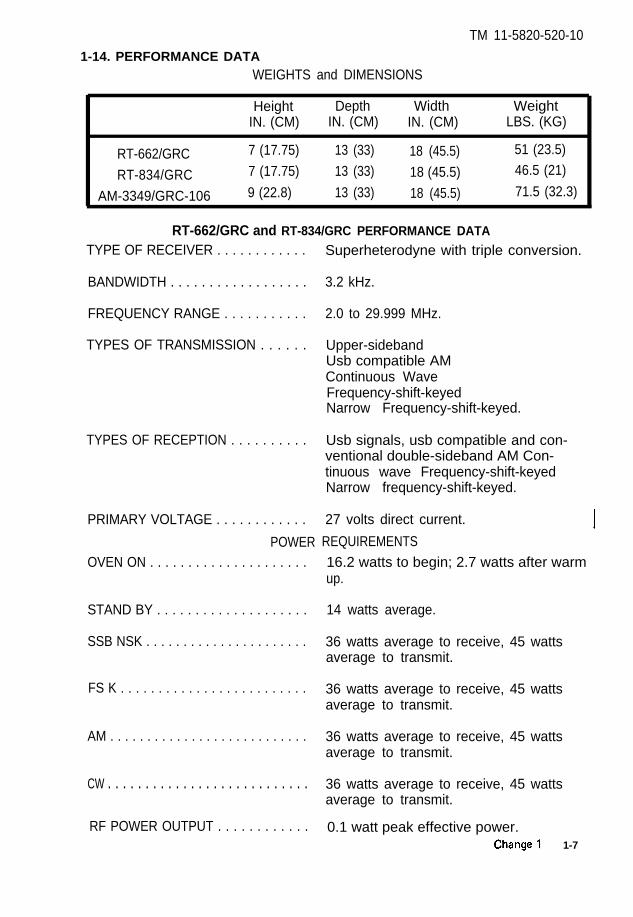
1-14. PERFORMANCE DATA
TM 11-5820-520-10
WEIGHTS and DIMENSIONS
Height Depth Width WeightIN. (CM) IN. (CM) IN. (CM) LBS. (KG)
RT-662/GRC 7 (17.75) 13 (33) 18 (45.5) 51 (23.5)
RT-834/GRC 7 (17.75) 13 (33) 18 (45.5) 46.5 (21)
AM-3349/GRC-106 9 (22.8) 13 (33) 18 (45.5) 71.5 (32.3)
RT-662/GRC and RT-834/GRC PERFORMANCE DATA
TYPE OF RECEIVER . . . . . . . . . . . .
BANDWIDTH . . . . . . . . . . . . . . . . . .
FREQUENCY RANGE . . . . . . . . . . .
TYPES OF TRANSMISSION . . . . . .
TYPES OF RECEPTION . . . . . . . . . .
PRIMARY VOLTAGE . . . . . . . . . . . .
POWEROVEN ON . . . . . . . . . . . . . . . . . . . . .
STAND BY . . . . . . . . . . . . . . . . . . . .
SSB NSK . . . . . . . . . . . . . . . . . . . . . .
FS K . . . . . . . . . . . . . . . . . . . . . . . . .
AM . . . . . . . . . . . . . . . . . . . . . . . . . . .
CW . . . . . . . . . . . . . . . . . . . . . . . . . . .
RF POWER OUTPUT . . . . . . . . . . . .
Superheterodyne with triple conversion.
3.2 kHz.
2.0 to 29.999 MHz.
Upper-sidebandUsb compatible AMContinuous WaveFrequency-shift-keyedNarrow Frequency-shift-keyed.
Usb signals, usb compatible and con-ventional double-sideband AM Con-tinuous wave Frequency-shift-keyedNarrow frequency-shift-keyed.
27 volts direct current.
REQUIREMENTS
16.2 watts to begin; 2.7 watts after warmup.
14 watts average.
36 watts average to receive, 45 wattsaverage to transmit.
36 watts average to receive, 45 wattsaverage to transmit.
36 watts average to receive, 45 wattsaverage to transmit.
36 watts average to receive, 45 wattsaverage to transmit.
0.1 watt peak effective power. 1-7
TM 11-5820-520-10
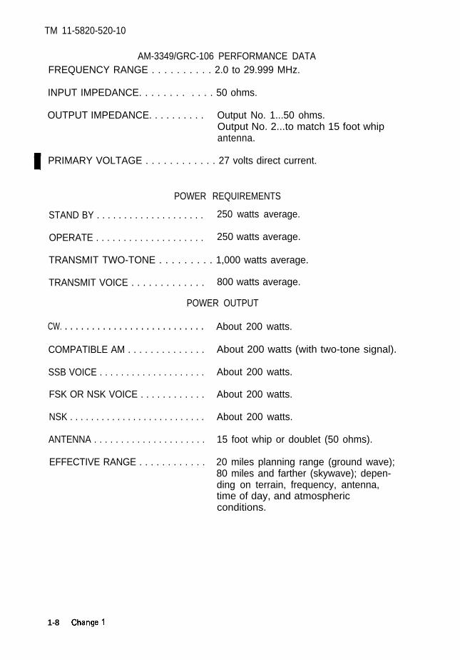
AM-3349/GRC-106 PERFORMANCE DATAFREQUENCY RANGE . . . . . . . . . . 2.0 to 29.999 MHz.
INPUT IMPEDANCE. . . . . . . . . . . . 50 ohms.
OUTPUT IMPEDANCE. . . . . . . . . . Output No. 1...50 ohms.Output No. 2...to match 15 foot whipantenna.
PRIMARY VOLTAGE . . . . . . . . . . . . 27 volts direct current.
POWER REQUIREMENTS
STAND BY . . . . . . . . . . . . . . . . . . . . 250 watts average.
OPERATE . . . . . . . . . . . . . . . . . . . . 250 watts average.
TRANSMIT TWO-TONE . . . . . . . . . 1,000 watts average.
TRANSMIT VOICE . . . . . . . . . . . . . 800 watts average.
POWER OUTPUT
CW. . . . . . . . . . . . . . . . . . . . . . . . . . .
COMPATIBLE AM . . . . . . . . . . . . . .
SSB VOICE . . . . . . . . . . . . . . . . . . . .
FSK OR NSK VOICE . . . . . . . . . . . .
NSK . . . . . . . . . . . . . . . . . . . . . . . . . .
ANTENNA . . . . . . . . . . . . . . . . . . . . .
EFFECTIVE RANGE . . . . . . . . . . . .
About 200 watts.
About 200 watts (with two-tone signal).
About 200 watts.
About 200 watts.
About 200 watts.
15 foot whip or doublet (50 ohms).
20 miles planning range (ground wave);80 miles and farther (skywave); depen-ding on terrain, frequency, antenna,time of day, and atmosphericconditions.
1-8
TM 11-5820-520-10
Section Ill. TECHNICAL PRINCIPLES OF OPERATION
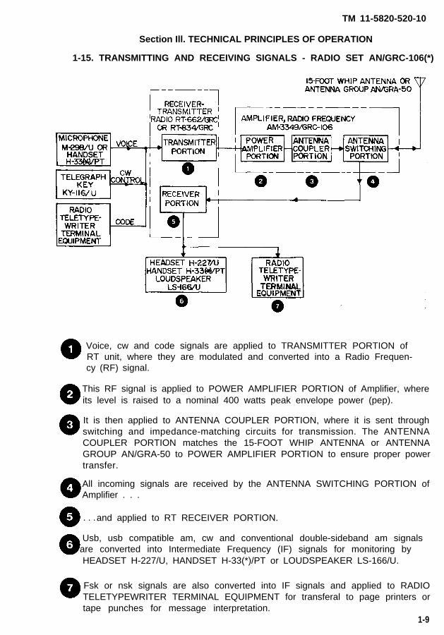
1-15. TRANSMITTING AND RECEIVING SIGNALS - RADIO SET AN/GRC-106(*)
Voice, cw and code signals are applied to TRANSMITTER PORTION ofRT unit, where they are modulated and converted into a Radio Frequen-cy (RF) signal.
This RF signal is applied to POWER AMPLIFIER PORTION of Amplifier, whereits level is raised to a nominal 400 watts peak envelope power (pep).
It is then applied to ANTENNA COUPLER PORTION, where it is sent throughswitching and impedance-matching circuits for transmission. The ANTENNACOUPLER PORTION matches the 15-FOOT WHIP ANTENNA or ANTENNAGROUP AN/GRA-50 to POWER AMPLIFIER PORTION to ensure proper powertransfer.
All incoming signals are received by the ANTENNA SWITCHING PORTION ofAmplifier . . .
. . .and applied to RT RECEIVER PORTION.
Usb, usb compatible am, cw and conventional double-sideband am signalsare converted into Intermediate Frequency (IF) signals for monitoring byHEADSET H-227/U, HANDSET H-33(*)/PT or LOUDSPEAKER LS-166/U.
Fsk or nsk signals are also converted into IF signals and applied to RADIOTELETYPEWRITER TERMINAL EQUIPMENT for transferal to page printers ortape punches for message interpretation.
1-9

TM 11-5820-520-10
CHAPTER 2
OPERATING lNSTRUCTIONS
SUBJECT
AM-3349/GRC-106 . . . . . . . . . . . . . . . . . . . . . . . . . . . . . . . . . . . . . . . . .Antijamming . . . . . . . . . . . . . . . . . . . . . . . . . . . . . . . . . . . . . . . . . . . . . .Assembly and Preparation for Use . . . . . . . . . . . . . . . . . . . . . . . . . . .Controls and indicators . . . . . . . . . . . . . . . . . . . . . . . . . . . . . . . . . . . .Destruction to Prevent Enemy Use . . . . . . . . . . . . . . . . . . . . . . . . . . .Emergency Stopping Procedure . . . . . . . . . . . . . . . . . . . . . . . . . . . . .Operating Procedure . . . . . . . . . . . . . . . . . . . . . . . . . . . . . . . . . . . . . . .Operation, Unusual . . . . . . . . . . . . . . . . . . . . . . . . . . . . . . . . . . . . . . . .Operation, Usual . . . . . . . . . . . . . . . . . . . . . . . . . . . . . . . . . . . . . . . . . .PMCS Chart . . . . . . . . . . . . . . . . . . . . . . . . . . . . . . . . . . . . . . . . . . . . . .Preparation for Movement . . . . . . . . . . . . . . . . . . . . . . . . . . . . . . . . . .Preventive Maintenance . . . . . . . . . . . . . . . . . . . . . . . . . . . . . . . . . . . .Radio Jamming . . . . . . . . . . . . . . . . . . . . . . . . . . . . . . . . . . . . . . . . . . .RT-662/GRC and RT-834/GRC . . . . . . . . . . . . . . . . . . . . . . . . . . . . . . . .Starting Procedure . . . . . . . . . . . . . . . . . . . . . . . . . . . . . . . . . . . . . . . .Stopping Procedure . . . . . . . . . . . . . . . . . . . . . . . . . . . . . . . . . . . . . . . .To Receive Signals . . . . . . . . . . . . . . . . . . . . . . . . . . . . . . . . . . . . . . . .To Transmit Signals . . . . . . . . . . . . . . . . . . . . . . . . . . . . . . . . . . . . . . . .Tuning Procedure . . . . . . . . . . . . . . . . . . . . . . . . . . . . . . . . . . . . . . . . .Warm Up Procedure . . . . . . . . . . . . . . . . . . . . . . . . . . . . . . . . . . . . . .
PAGE
2-102-472-212-12-482-442-402-462-212-202-452-162-462-12-322-442-402-412-342-29
2-0
TM 11-5820-520-10
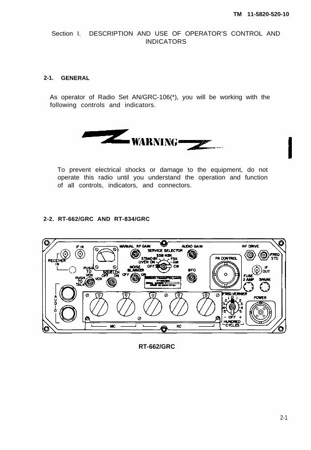
Section I. DESCRIPTION AND USE OF OPERATOR’S CONTROL ANDlNDICATORS
2-1. GENERAL
As operator of Radio Set AN/GRC-106(*), you will be working with thefollowing controls and indicators.
To prevent electrical shocks or damage to the equipment, do notoperate this radio until you understand the operation and functionof all controls, indicators, and connectors.
2-2. RT-662/GRC AND RT-834/GRC
RT-662/GRC
2-1

TM 11-5820-520-10
RT-834/GRC
AM-3349/GRC-106
2-2
TM 11-5820-520-10
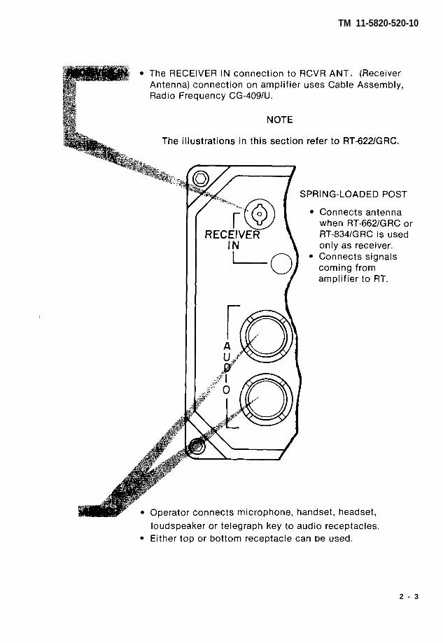
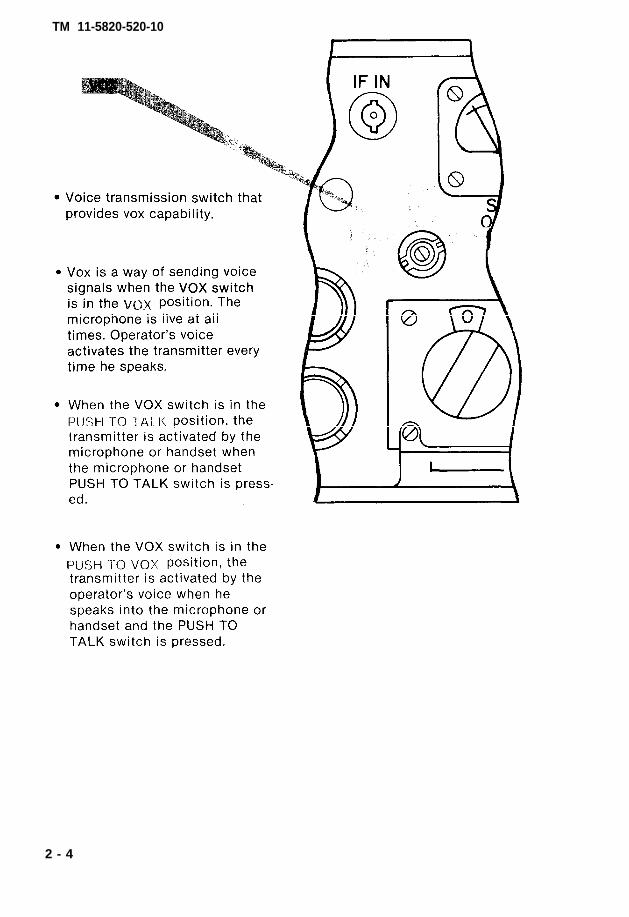
2 - 3
TM 11-5820-520-10
2 - 4

TM 11-5820-520-10
2-5

TM 11-5820-520-10
2-6
TM 11-5820-520-10
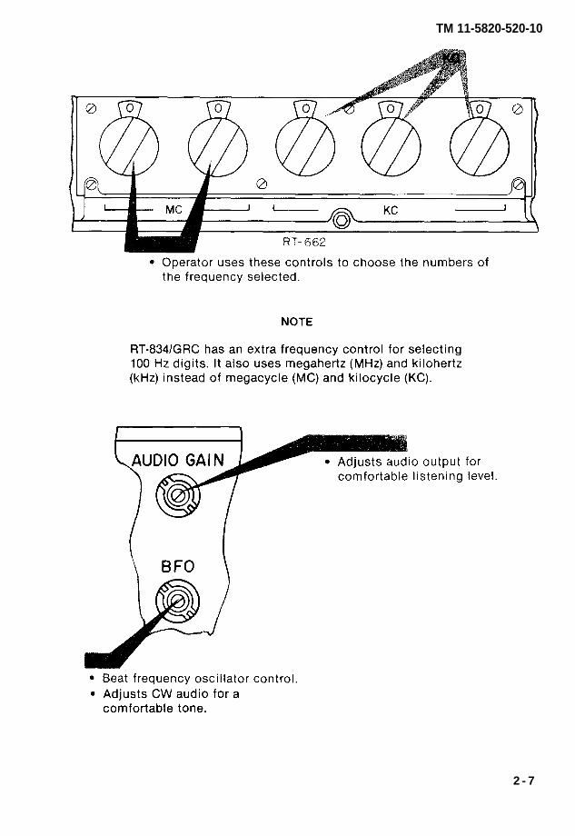
2 - 7
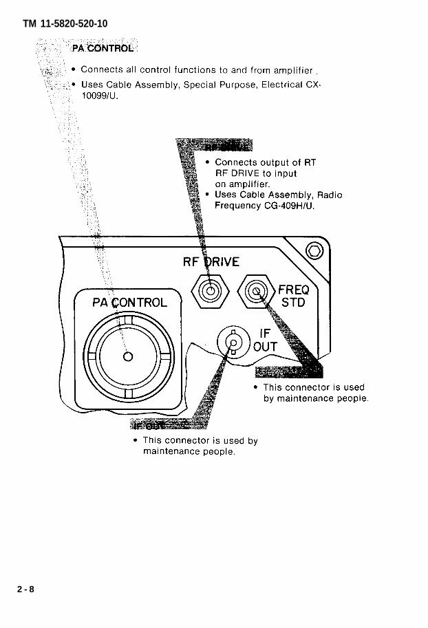
TM 11-5820-520-10
2 - 8
TM 11-5820-520-10
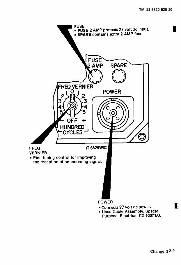
Change 1 2-9

TM 11-5820-520-10
2-3. AMPLIFIER AM-3349/GRC-106
Be very careful when you are working around these antennas andantenna connectors. High voltages exist at these points.
WHIP Lead of 15-foot whip antenna connects here.
50 OHM LINE Flag switch covers 50ohm connector.
Connects doubletantenna.
GRD● Spring-loaded binding post
for grounding radio set tovehicle chassis.
RCVR ANT.
● Receiver antenna connector.● Connects RCVR ANT. output to
RECEIVER IN input on RT whenradio set is receiving.
2 - 1 0
TM 11-5820-520-10
2-11
TM 11-5820-520-10
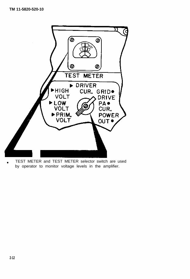
TEST METER and TEST METER selector switch are usedby operator to monitor voltage levels in the amplifier.
2-12

TM 11-5820-520-10
2-13

TM 11-5820-520-10
2-14

TM 11-5820-520-10
Change 1 2-15

TM 11-5820-520-10
Section Il. PREVENTIVE MAINTENANCE CHECKS AND SERVICES
2-4. PREVENTIVE MAINTENANCE
Operator’s Preventive Maintenance Checks and Services (PMCS) is the re-quired daily and weekly inspection and care of your equipment necessary tokeep it in good operating condition.
a. Tools, Materials, and Equipment Required For Maintenance
No tools or equipment are required for operator maintenance.The following cleaning materials will be useful to the operator:
Lint-free cloths Soft bristle brush Dishwashing compound or detergent Cleaning compound (NSN 6859-00-597-9765)
NOTE
If your radio set must be in USE ALL THE TIME, checkand service those items that can be checked and servicedwithout stopping its operation. Make COMPLETEchecks and services ONLY when the radio set is finally
SHUT DOWN.
b. Routine Checks
Routine services are a collection of checks and observations performed by the operator at all times. Routine services are not listed in the preventivemaintenance checks and services table, in order to separate the nonopera-tional from the operational services.
You should perform the following routines as necessary.
Clean Dust Wash Check for cut or frayed cables Check for dented, bent, or broken
components Check to see that items not in use
are properly stored Check for rusting Check controls for smooth operation Check for completeness and currentchanges to publications.
2-16

TM 11-5820-520-10
●
●
●
Cover unused receptaclesCheck for loose nuts, bolts, andconnectorsCheck that grounds are notdamaged and that connectionsare securely attachedCheck for completeness ofequipment
Service the following
Ž Radio antennas• Radio equipment
items:
● Transmitter heat exchanger
C. Explanation of INTERVAL column of PMCS chart
NOTE
Always keep in mind all WARNINGS and CAUTIONSwhen PMCS are performed.
Do your Weekly (W), Before Operating (B), After Operating (A), andMonthly (M) PMCS to insure that the radio set is functioning properly.
NOTE
ALL PMCS must be done as regularly scheduled andalso under the following conditions:
• Before the radio set is used on a mission.• When the radio set is first installed.● When the radio set is re-installed after being
removed for any reason.● When you are operating the radio set for the first
time.
d. Explanation of EQUIPMENT IS NOT READY/AVAILABLE IF:column of PMCS chart.
● This column tells the condition under which the equipmentcannot perform the assigned mission requirements.
Change 1 2-17

TM 11-5820-520-10
TM 11-5820-520-10
NOTE
The procedures column in your PMCS chart tells youhow to perform the required checks and services.Carefully follow these instructions. If tools are needed,or the chart instructions tell you, get organizationalmaintenance to do the necessary work.
NOTE
If any portion of your radio set fails to operate refer toChapter 3 under Troubleshooting for possible problems.Report any malfunctions or failures on the proper DAForm 2404 or refer to DA Pam 738-750.
DA FORM 2404, EQUIPMENT INSPECTION AND MAINTENANCE WORKSHEET
2-18 Change 1
Table 2-1.S
ection III
Chapter 2
Table 2-1.
TM
11-5820-520-10
Change 1
2-19

Table 2-1 (con't).
Table 2-1
TM
11-5820-520-10
2-2
0C
hange 1

TM 11-5820-520-10Section Ill. OPERATION UNDER USUAL CONDITIONS
2-6. ASSEMBLY AND PREPARATION FOR USE
a. MOUNTING PROCEDURE●
●
Grasp the release handles on RT Mount and pull them forward from theirsecuring holes while turning them toward the outside of the unit.
Position RT on RT Mount so that the cleats on the bottom of the RT unitsit securely in the holes of RT Mount.
NOTE
For installation requiring side-by-side mounting ofthe RT and Amplifier, two sets of shorter crossbarassemblies and another RT Mount would be needed.
2-21
●
●
●
●
TM 11-5820-520-10
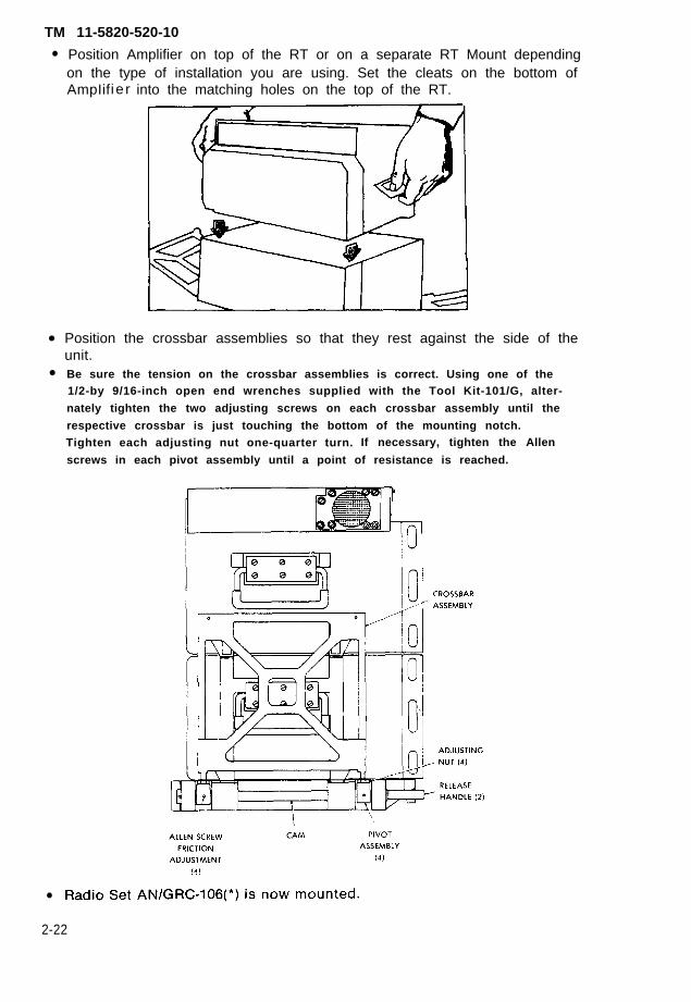
Position Amplifier on top of the RT or on a separate RT Mount dependingon the type of installation you are using. Set the cleats on the bottom ofAmpIifi e r into the matching holes on the top of the RT.
Position the crossbar assemblies so that they rest against the side of theunit.Be sure the tension on the crossbar assemblies is correct. Using one of the1/2-by 9/16-inch open end wrenches supplied with the Tool Kit-101/G, alter-
nately tighten the two adjusting screws on each crossbar assembly until the
respective crossbar is just touching the bottom of the mounting notch.Tighten each adjusting nut one-quarter turn. If necessary, tighten the Allen
screws in each pivot assembly until a point of resistance is reached.
2-22

●
●
TM 11-5820-520-10
Grasp the release handles on RT Mount and pull them forward while turn-ing them toward the outside of the unit. Rotate the handles back and pushthem into the holes in the front of RT Mount. If the tension is correct, nobinding will occur and the equipment will be secured on RT Mount. Ifbinding is present, alternately loosen the two adjusting nuts until bindingdisappears.
NOTE
Adjusting nuts must always be tight enoughto secure radio.
Pull handles and turn them to the outside. If friction is correct the crossbarassemblies will move away from the set and the handles and crossbars willstay where they are released.
Radio Set AN/GRC-106(*) is now mounted.
NOTE
Crew is authorized use of Tool
NOTE
Kit-101/G in MAC.
To install AN/GRC-106(*) into the High MobilityMulti-Purpose Wheeled Vehicle (HMMWV) useInstallation Kit MK-2506 (NSN 5820-01-208-1905)with 100A kit (NSN 2920-01-199-2393) for power.
Change 1 2-23

TM 11-5820-520-10
Dangerous voltages exist at the Amplifier 50 OHM LINEand whip antenna connectors. Be very careful whenworking with the antenna and antenna connectors.
b. GROUNDING AN/GRC-106(*)● Set Amplifier PRIM. PWR. switch and RT SERVICE SELECTOR switch to
OFF.
● Connect ground cable (bonding jumper) to spring-loaded ground bindingpost (GRD) on Amplifier.
● Connect lug at end of grounding cable to chassis of vehicle.
2-24
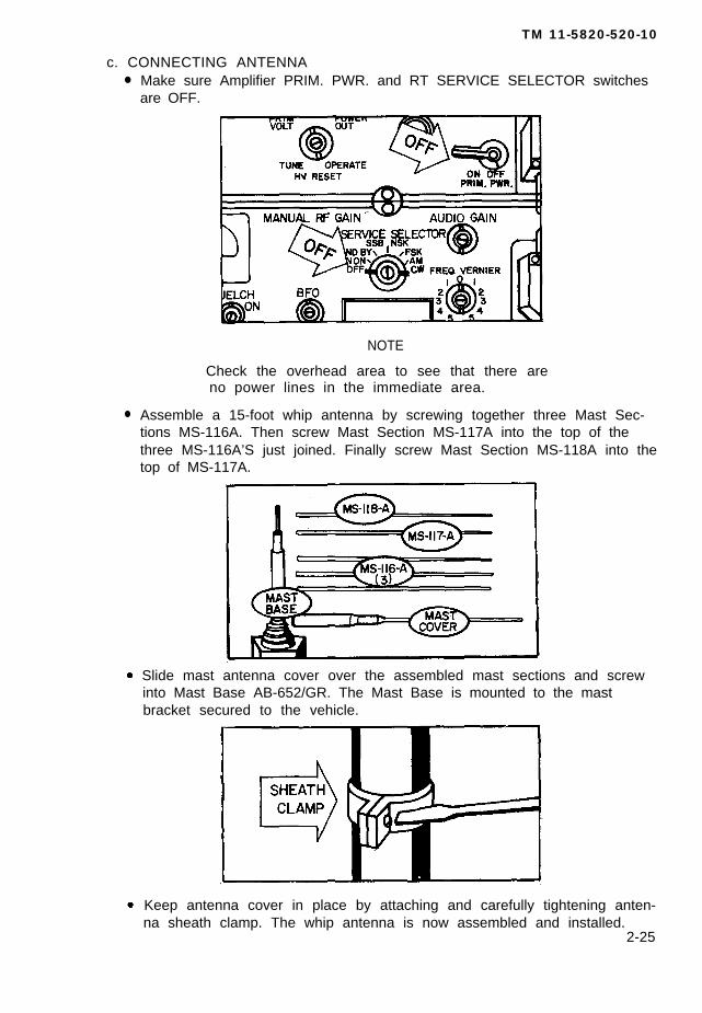
c. CONNECTING ANTENNA●
●
TM 11-5820-520-10
Make sure Amplifier PRIM. PWR. and RT SERVICE SELECTOR switchesare OFF.
NOTE
Check the overhead area to see that there areno power lines in the immediate area.
Assemble a 15-foot whip antenna by screwing together three Mast Sec-tions MS-116A. Then screw Mast Section MS-117A into the top of thethree MS-116A’S just joined. Finally screw Mast Section MS-118A into thetop of MS-117A.
Slide mast antenna cover over the assembled mast sections and screwinto Mast Base AB-652/GR. The Mast Base is mounted to the mastbracket secured to the vehicle.
Keep antenna cover in place by attaching and carefully tightening anten-na sheath clamp. The whip antenna is now assembled and installed.
2-25

T M 1 1 - 5 8 2 0 - 5 2 0 - 1 0
● Connect antenna lead connector to whip antenna terminal on Amplifier.Use electrical lead CX-10171/U.
NOTE
Before connecting antenna lead check all contactsfor rust or corrosion. Clean all contacts till shineyand apply a light coating of silicone(NSN 6850-00-880-7616).
● Thread the antenna lead through insulators on left hand crossbarassembly. Connect the other end to binding post on AB-652/GR.Amplifier is now grounded and the antenna is connected.
2-26

TM 11-5820-520-10
NOTE
To instal l Antenna Group AN/GRA-50 (DoubletAntenna), refer to TM 11-5820-467-15. Connect theAN/GRA-50 radio frequency (rf) transmission cable tothe AM-3349/GRC 50 OHM LINE receptacle.
CAUTION
Before connecting Cable Assembly, Special Purpose,Electrical CX-10071/U to POWER jack on RT, be sureboth pins C and D on J24 are grounded. If only one pinhas been grounded, the lead between the pin andground might not handle the load and burn open. Ifmeasurements indicate that only one pin is grounded,request a higher category of maintenance to ground theother pin.
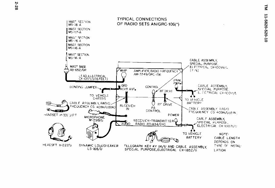
d. TYPICAL CONNECTIONS
The figure on the following page is for typical connections of radio setsAN/GRC-106(*).
●
●
●
●
Connect one Cable Assembly, Special Purpose, Electrical CX-10071/U tothe Amplifier PRIM. PWR. connector and one to the RT POWER connector.Dress these two cables along the vehicle chassis according to the in-stallation unit instructions.
Cut these cables to the required length. Solder two terminal lugs or apower connector to the cable leads. Connect one terminal lug to thepositive center conductor and the other terminal lug to the negativebraided loom shield. Connect the terminal lugs or the power connector tothe dc source.
These two CX-10071/U can be connected to a 27-volt dc power source byone of the following methods:
1. Directly to vehicle battery.2. To vehicle battery through Electrical Transient Suppressor, MX-
7778/GRC (TM 11-5915 -223-12).3. To a dc power source, such as PP-4763/GRC (TM 11-5820-765-12).
Connect one Cable Assembly, Special Purpose, Electrical CX-10099/U toAmplifier CONTROL connector and RT unit PA CONTROL connector byturning screw handle on CX-10099/U to the right until it is firmly attachedto the cable connectors.
Connect one Cable Assembly Radio, Frequency CG-409H/U toAmplifier RF DRIVE connector and RT unit RF DRIVE connector bydepressing the coaxial connector on CG-409H/U and turning it to theright. Use this same procedure to connect another CG-409H/U toAmplifier RCVR ANT. connector and RT unit RECEIVER IN connector.
2-27
TM
11-5820-520-10
2-28
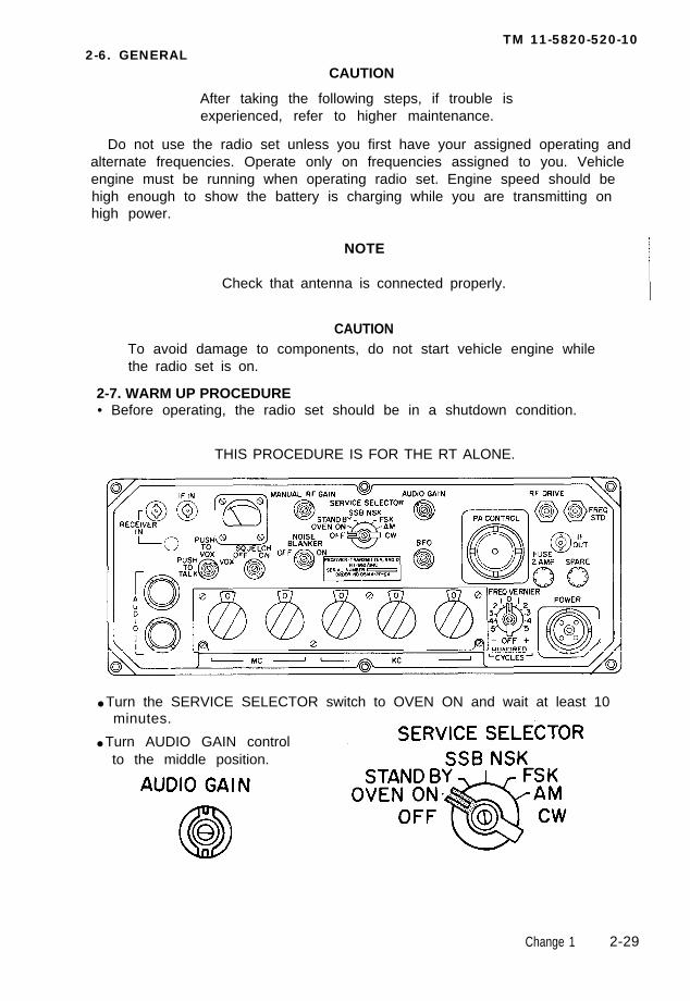
TM 11-5820-520-102-6. GENERAL
CAUTION
After taking the following steps, if trouble isexperienced, refer to higher maintenance.
Do not use the radio set unless you first have your assigned operating andalternate frequencies. Operate only on frequencies assigned to you. Vehicleengine must be running when operating radio set. Engine speed should behigh enough to show the battery is charging while you are transmitting onhigh power.
NOTE
Check that antenna is connected properly.
CAUTIONTo avoid damage to components, do not start vehicle engine whilethe radio set is on.
2-7. WARM UP PROCEDURE• Before operating, the radio set should be in a shutdown condition.
THIS PROCEDURE IS FOR THE RT ALONE.
● Turn the SERVICE SELECTOR switch to OVEN ON and wait at least 10minutes.
● Turn AUDIO GAIN controlto the middle position.
Change 1 2-29

TM 11-5820-520-10
● Turn● Turn
MANUAL RF GAIN controlSQUELCH switch to OFF.
all the way
• Turn FREQ VERNIER control to OFF.
● Turn VOX switch to PUSH TO TALK.
● Turn BFO control to the middle position.
• Turn NOISE BLANKER switch to OFF.
NOTE
This applies to RT-662/GRC only.
to the right.
2-30

TM 11-5820-520-10
2 - 3 1
TM 11-5820-520-10
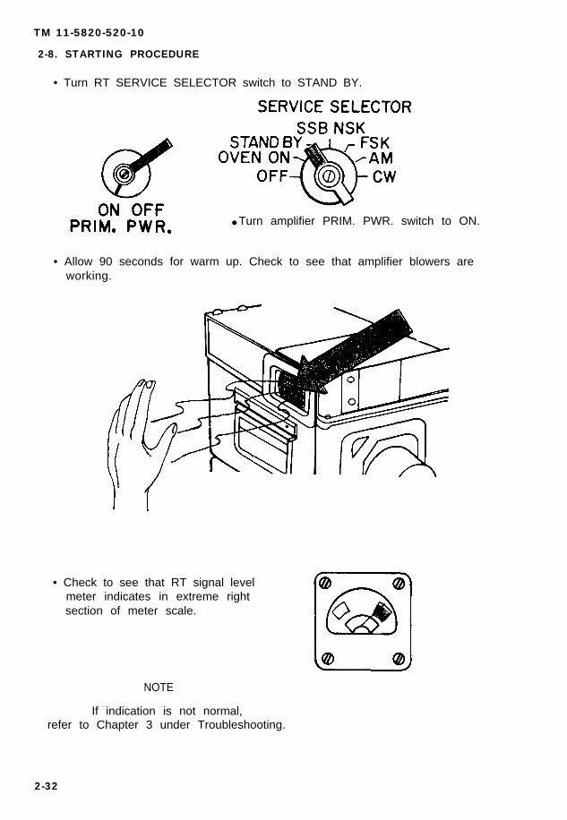
2-8. STARTING PROCEDURE
• Turn RT SERVICE SELECTOR switch to STAND BY.
● Turn amplifier PRIM. PWR. switch to ON.
• Allow 90 seconds for warm up. Check to see that amplifier blowers areworking.
• Check to see that RT signal levelmeter indicates in extreme rightsection of meter scale.
NOTE
If indication is not normal,refer to Chapter 3 under Troubleshooting.
2-32

TM 11-5820-520-10
● Turn RT SERVICE SELECTOR switch to SSB NSK.
RT signal level meter will return to extreme left section of meter scale.
● Set amplifier TEST METER switch to PRIM. VOLT.
2-33
TM 11-5820-520-10
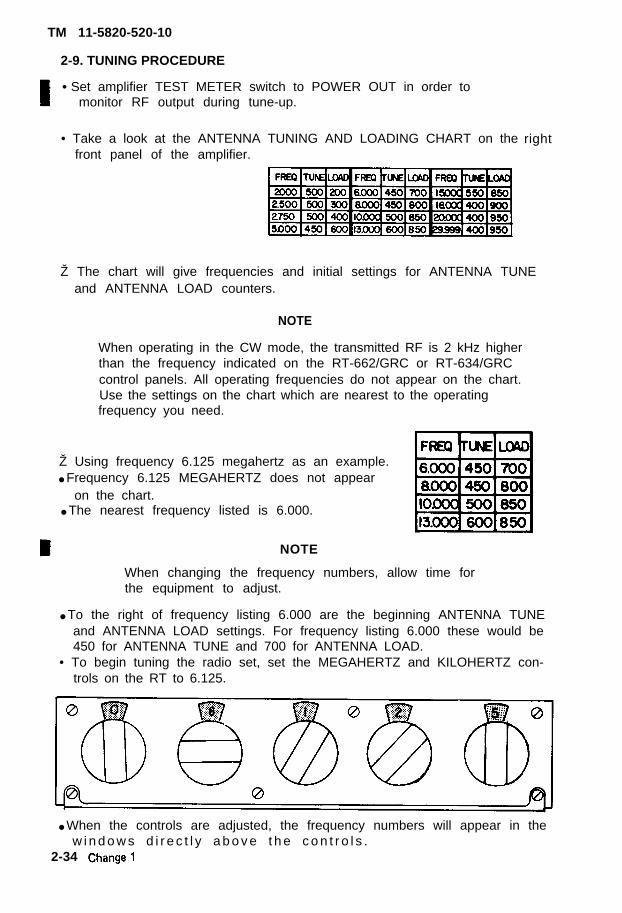
2-9. TUNING PROCEDURE
• Set amplifier TEST METER switch to POWER OUT in order tomonitor RF output during tune-up.
• Take a look at the ANTENNA TUNING AND LOADING CHART on thefront panel of the amplifier.
Ž The chart will give frequencies and initial settings for ANTENNA TUNEand ANTENNA LOAD counters.
NOTE
When operating in the CW mode, the transmitted RF is 2 kHz higherthan the frequency indicated on the RT-662/GRC or RT-634/GRCcontrol panels. All operating frequencies do not appear on the chart.Use the settings on the chart which are nearest to the operatingfrequency you need.
Ž Using frequency 6.125 megahertz as an example.● Frequency 6.125 MEGAHERTZ does not appear
on the chart.● The nearest frequency listed is 6.000.
right
NOTE
When changing the frequency numbers, allow time forthe equipment to adjust.
● To the right of frequency listing 6.000 are the beginning ANTENNA TUNEand ANTENNA LOAD settings. For frequency listing 6.000 these would be450 for ANTENNA TUNE and 700 for ANTENNA LOAD.
• To begin tuning the radio set, set the MEGAHERTZ and KILOHERTZ con-trols on the RT to 6.125.
● When the controls are adjusted, the frequency numbers will appear in thew i n d o w s d i r e c t l y a b o v e t h e c o n t r o l s .
2-34
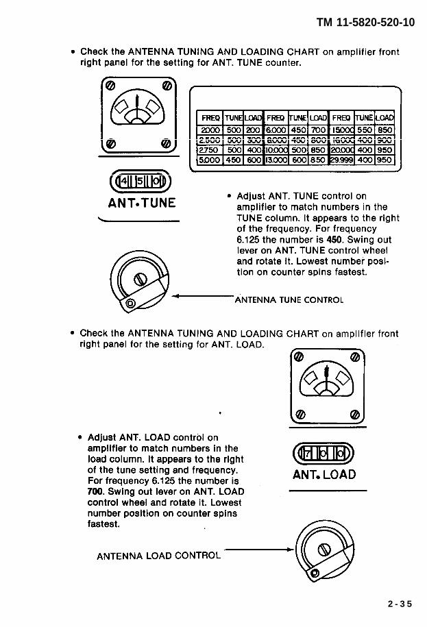
TM 11-5820-520-10
2 - 3 5
TM 11-5820-520-10
●
●
●
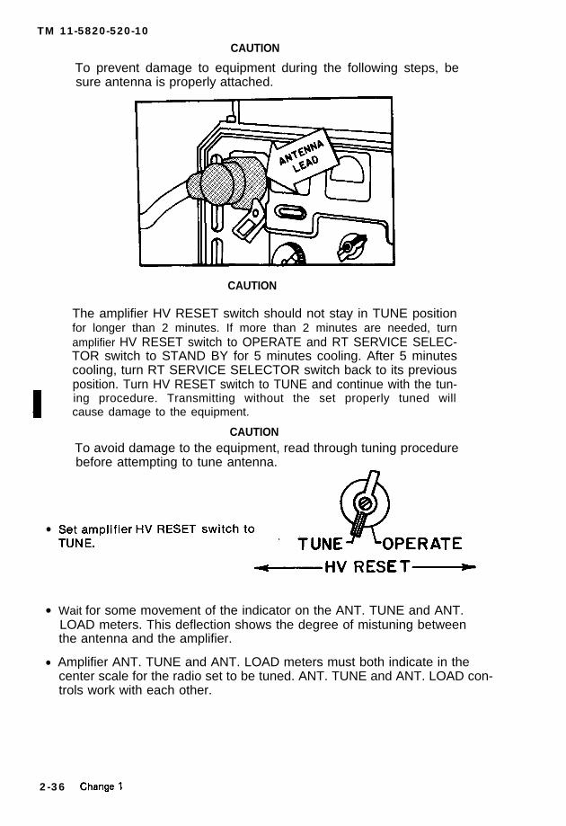
CAUTION
To prevent damage to equipment during the following steps, besure antenna is properly attached.
CAUTION
The amplifier HV RESET switch should not stay in TUNE positionfor longer than 2 minutes. If more than 2 minutes are needed, turnamplifier HV RESET switch to OPERATE and RT SERVICE SELEC-TOR switch to STAND BY for 5 minutes cooling. After 5 minutescooling, turn RT SERVICE SELECTOR switch back to its previousposition. Turn HV RESET switch to TUNE and continue with the tun-ing procedure. Transmitting without the set properly tuned willcause damage to the equipment.
CAUTIONTo avoid damage to the equipment, read through tuning procedurebefore attempting to tune antenna.
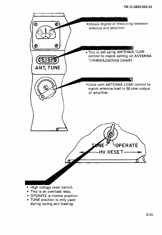
Wait for some movement of the indicator on the ANT. TUNE and ANT.LOAD meters. This deflection shows the degree of mistuning betweenthe antenna and the amplifier.
Amplifier ANT. TUNE and ANT. LOAD meters must both indicate in thecenter scale for the radio set to be tuned. ANT. TUNE and ANT. LOAD con-trols work with each other.
2-36

TM 11-5820-520-10
NOTE
Antenna tuning procedure must be followed preciselyto ensure finest tuning.
● Select meter that indicates farthest from center and adjust to middleposition.
● Now adjust second meter to middle position.
●
●
NOTE
This procedure may take many adjustments tothe TUNE and LOAD meters refuse to center,
complete. If bothslowly turn both
controls at the same time in the same direction. If both meters areoff center to the left, for example, slowly turn both controls tothe right.
Continue to alternately adjust meters to middle positions until bothindicate center scale at the same time.
NOTE
If indication is not normal, check TroubleshootingTable in Chapter 3.
Amplifier is tuned when both the ANT. TUNE and ANT. LOAD meters in-dicate in the center scale at the same time.
Change 1 2 - 3 7
TM 11-5820-520-10
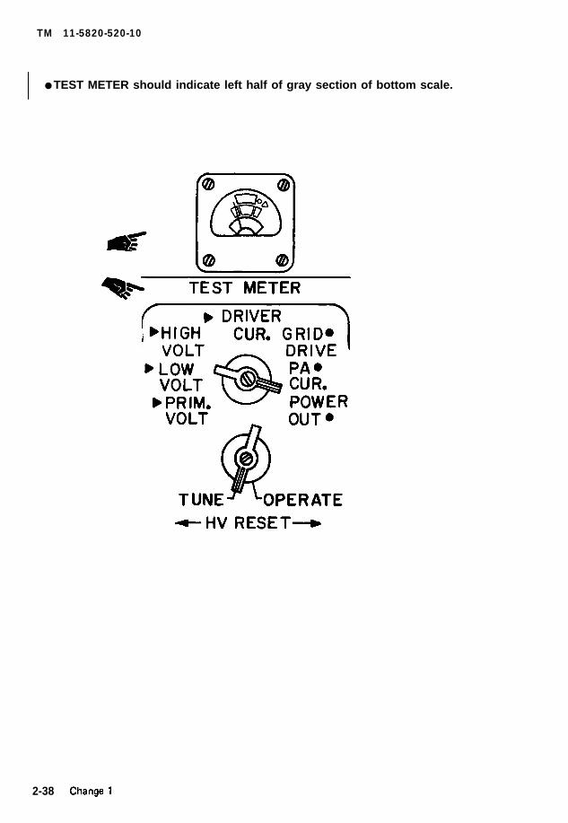
● TEST METER should indicate left half of gray section of bottom scale.
2-38
TM 11-5820-520-10
●
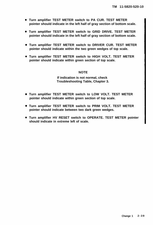
Turn amplifier TEST METER switch to PA CUR. TEST METERpointer should indicate in the left half of gray section of bottom scale.
Turn amplifier TEST METER switch to GRID DRIVE. TEST METERpointer should indicate in the left half of gray section of bottom scale.
Turn amplifier TEST METER switch to DRIVER CUR. TEST METERpointer should indicate within the two green wedges of top scale.
Turn amplifier TEST METER switch to HIGH VOLT. TEST METERpointer should indicate within green section of top scale.
NOTE
If indication is not normal, checkTroubleshooting Table, Chapter 3.
Turn amplifier TEST METER switch to LOW VOLT. TEST METERpointer should indicate within green section of top scale.
Turn amplifier TEST METER switch to PRIM VOLT. TEST METERpointer should indicate between two dark green wedges.
Turn amplifier HV RESET switch to OPERATE. TEST METER pointershould indicate in extreme left of scale.
Change 1 2 - 3 9
TM 11-5820-520-10
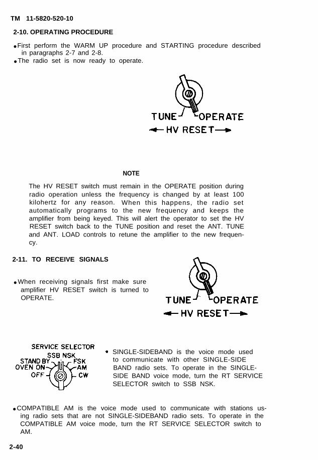
2-10. OPERATING PROCEDURE
● First perform the WARM UP procedure and STARTING procedure describedin paragraphs 2-7 and 2-8.
● The radio set is now ready to operate.
NOTE
The HV RESET switch must remain in the OPERATE position duringradio operation unless the frequency is changed by at least 100kilohertz for any reason. When this happens, the radio setautomatically programs to the new frequency and keeps theamplifier from being keyed. This will alert the operator to set the HVRESET switch back to the TUNE position and reset the ANT. TUNEand ANT. LOAD controls to retune the amplifier to the new frequen-cy.
2-11. TO RECEIVE SIGNALS
● When receiving signals first make sureamplifier HV RESET switch is turned toOPERATE.
SINGLE-SIDEBAND is the voice mode usedto communicate with other SINGLE-SIDEBAND radio sets. To operate in the SINGLE-SIDE BAND voice mode, turn the RT SERVICESELECTOR switch to SSB NSK.
● COMPATIBLE AM is the voice mode used to communicate with stations us-ing radio sets that are not SINGLE-SIDEBAND radio sets. To operate in theCOMPATIBLE AM voice mode, turn the RT SERVICE SELECTOR switch toAM.
2-40
TM 11-5820-520-10
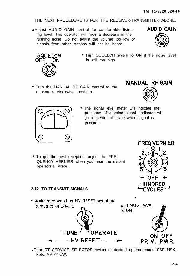
THE NEXT PROCEDURE IS FOR THE RECEIVER-TRANSMITTER ALONE.
● Adjust AUDIO GAIN control for comfortable listen-ing level. The operator will hear a decrease in therushing noise. Do not adjust the volume too low orsignals from other stations will not be heard.
• Turn SQUELCH switch to ON if the noise levelis still too high.
• Turn the MANUAL RF GAIN control to themaximum clockwise position.
• The signal level meter will indicate thepresence of a voice signal. Indicator willgo to center of scale when signal ispresent.
• To get the best reception, adjust the FRE-QUENCY VERNIER when you hear the distantoperator’s voice.
2-12. TO TRANSMIT SIGNALS
● Turn RT SERVICE SELECTOR switch to desired operate mode SSB NSK,FSK, AM or CW.
2-4
TM 11-5820-520-10
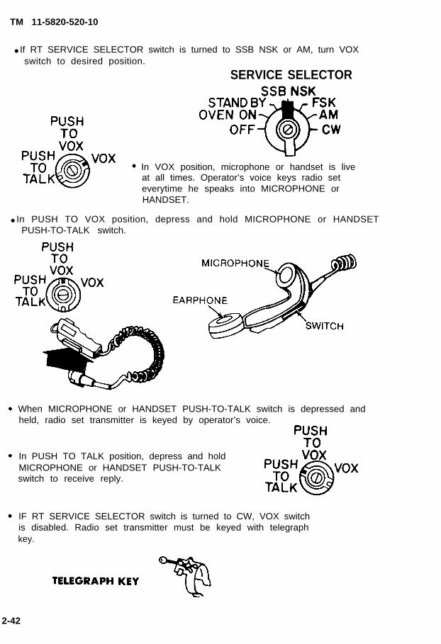
● If RT SERVICE SELECTOR switch is turned to SSB NSK or AM, turn VOXswitch to desired position.
SERVICE SELECTOR
● In VOX position, microphone or handset is liveat all times. Operator’s voice keys radio seteverytime he speaks into MICROPHONE orHANDSET.
● In PUSH TO VOX position, depress and hold MICROPHONE or HANDSETPUSH-TO-TALK switch.
When MICROPHONE or HANDSET PUSH-TO-TALK switch is depressed andheld, radio set transmitter is keyed by operator’s voice.
In PUSH TO TALK position, depress and holdMICROPHONE or HANDSET PUSH-TO-TALKswitch to receive reply.
IF RT SERVICE SELECTOR switch is turned to CW, VOX switchis disabled. Radio set transmitter must be keyed with telegraphkey.
2-42

TM 11-5820-520-10
●
●
If RT SERVICE SELECTOR switch is turned to FSK, VOX switch is disabledRadio set transmitter must be keyed by appropriate radio teletypewriterterminal equipment.
Audio accessories HANDSET, HEADSET, MICROPHONE, TELEGRAPH KEYor LOUDSPEAKER can be connected to either of the two AUDIO RECEP-TACLES on RT bottom left panel front.
2-43
TM 11-5820-520-10
2-13. STOPPING PROCEDURE
● Radio set can be put into stand by or shutdown condition. Complete shut-down takes 3 minutes. If radio set is to be off for 1 hour or less, placein stand by condition.
For stand by condition, keep amplifier HV RESET switch at OPERATE. TurnRT SERVICE SELECTOR switch to STAND BY.
If radio set is to be OFF for long period, follow complete shutdown pro-cedure:
Turn RT SERVICE SELECTOR switch to STAND BY. Give radio set 2minutes to cool down.
Keep amplifier HV RESET switch at OPERATE, whether radio set is turnedON or OFF.
● Turn amplifier PRIM. PWR. switch to OFF.
● Turn RT SERVICE SELECTOR switch to OFF.
2-14. EMERGENCY STOPPING PROCEDURE
● In an emergency, radio set can be stopped immediately.
To turn the radio set OFF in an emergency, turn RT SERVICE SELECTORswitch to OFF.
2-44
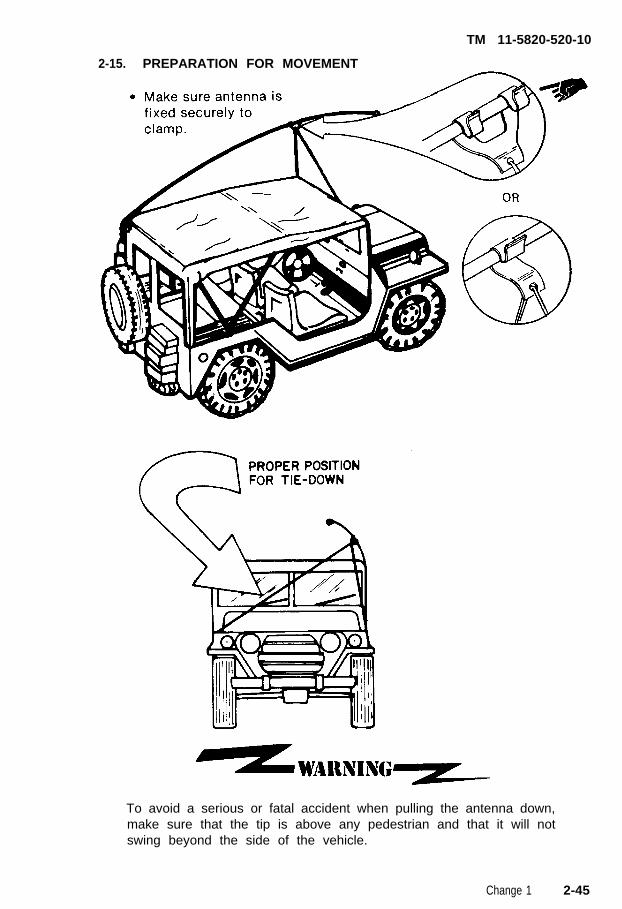
2-15.
TM 11-5820-520-10
PREPARATION FOR MOVEMENT
To avoid a serious or fatal accident when pulling the antenna down,make sure that the tip is above any pedestrian and that it will notswing beyond the side of the vehicle.
Change 1 2-45

TM 11-5820-520-10
Section IV. OPERATION UNDER UNUSUAL CONDITIONS
2-16. OPERATION AT LOW TEMPERATURES
●
●
●
●
●
Keep ice off antennas.Do not bend cables or cords suddenly.Check to see that ice or snow is not blocking amplifier blower port area.Make sure vehicle charging system can maintain a satistactory batterycharging rate.Keep radio set front panel controls free of ice.
NOTE
When operating the radio set in cold climates and shutdown is to befor 10 hours or less, set RT SERVICE SELECTOR switch to OVENON.
2-17. OPERATION IN DESERT AND DUSTY AREAS
• Keep equipment area as dust free as possible● if radio set is constantly exposed to sun, it should be protected with heat
reflecting paint. Ask supporting maintenance to take care of this.• Keep water in vehicle battery at proper level.
2-18. OPERATION IN TROPICAL CLIMATE
• Keep moisture and fungi off the equipment by wiping with a lint-freecloth.
● Do not operate equipment without covers for any long period of time.● Use the air conditioner, if available, to keep the temperature and humidity
down.
2-19. RADIO JAMMING
●
●
●
●
It is important to recognize that your radio may be being jammed. Jamming is the transmission of a strong, blocking signal on your frequency, makingit hard for you to communicate on the radio set.This signal may be from a friendly or unfriendly station.First make sure your receiver is-working right.Disable the antenna by grounding it.
NOTE
As soon as you know your radio isbeing jammed, tell your supervisor.
2 - 4 6
TM 11-5820-520-10
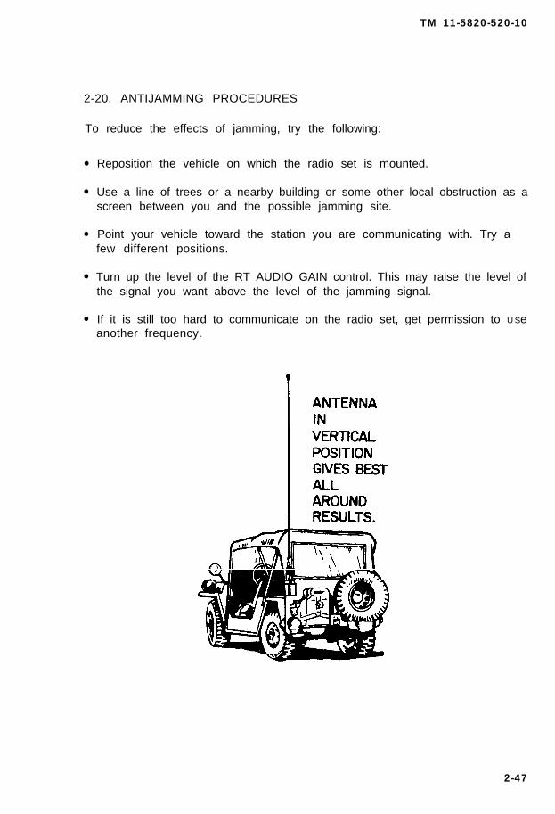
2-20. ANTIJAMMING PROCEDURES
To reduce the effects of jamming, try the following:
●
●
●
●
●
Reposition the vehicle on which the radio set is mounted.
Use a line of trees or a nearby building or some other local obstruction as ascreen between you and the possible jamming site.
Point your vehicle toward the station you are communicating with. Try afew different positions.
Turn up the level of the RT AUDIO GAIN control. This may raise the level ofthe signal you want above the level of the jamming signal.
If it is still too hard to communicate on the radio set, get permission to U Seanother frequency.
2-47
TM 11-5820-520-10
2-21. DESTRUCTION TO PREVENT ENEMY USE
NOTE
Demolition of the equipment will be carried out upon the order ofyour commander only. The method of destruction is dependentupon the amount of time available. The circumstances will deter-mine the manner in which the equipment will be destroyed.
● If you are pressed for time, smash the right side of the RT-662/GRC orRT-834/GRC with an ax.
● Cut the cables and wires.
To avoid serious injury or death, be extremelycareful when using gasoline for destruction.
● The TM is to be burned first. Burn as much of the equipment as possible.
To avoid serious injury or death, be extremelycareful with explosives and incendiary devices.Use these items only when the need is urgent,
● Use explosives to cause maximum destruction. Place explosive chargesinside the equipment after smashing the front panels. Grenades may beused to destroy small parts and wiring.
● Bury or scatter destroyed parts in slit trenches and foxholes. If neara waterway, throw parts into it.
2-48
TM 11-5820-520-10
CHAPTER 3
MAINTENANCE INSTRUCTIONS
SUBJECT PAGE
Cleaning the Radio Set . . . . . . . . . . . . . . . . . . . . . . . . . . . . . . . . . . . . . 3-1Fuse Replacement . . . . . . . . . . . . . . . . . . . . . . . . . . . . . . . . . . . . . . . 3-2General . . . . . . . . . . . . . . . . . . . . . . . . . . . . . . . . . . . . . . . . . . . . . . . . . 3-1Troubleshooting Procedures. . . . . . . . . . . . . . . . . . . . . . . . . . . . . . . 3-2Troubleshooting Table . . . . . . . . . . . . . . . . . . . . . . . . . . . . . . . . . . . . 3-3
(2-49 blank)/3-0

TM 11-5820-520-10
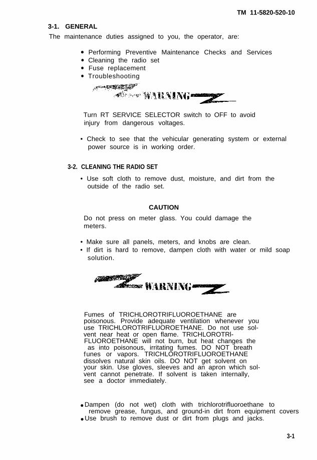
3-1. GENERAL
The maintenance duties assigned to you, the operator, are:
●
●
●
●
Performing Preventive Maintenance Checks and ServicesCleaning the radio setFuse replacementTroubleshooting
Turn RT SERVICE SELECTOR switch to OFF to avoidinjury from dangerous voltages.
• Check to see that the vehicular generating system or externalpower source is in working order.
3-2. CLEANING THE RADIO SET
• Use soft cloth to remove dust, moisture, and dirt from theoutside of the radio set.
CAUTION
Do not press on meter glass. You could damage themeters.
• Make sure all panels, meters, and knobs are clean.• If dirt is hard to remove, dampen cloth with water or mild soap
solution.
Fumes of TRICHLOROTRIFLUOROETHANE arepoisonous. Provide adequate ventilation whenever youuse TRICHLOROTRIFLUOROETHANE. Do not use sol-vent near heat or open flame. TRICHLOROTRl-FLUOROETHANE will not burn, but heat changes the
fas into poisonous, irritating fumes. DO NOT breathunes or vapors. TRICHLOROTRIFLUOROETHANE
dissolves natural skin oils. DO NOT get solvent onyour skin. Use gloves, sleeves and an apron which sol-vent cannot penetrate. If solvent is taken internally,see a doctor immediately.
● Dampen (do not wet) cloth with trichlorotrifluoroethane toremove grease, fungus, and ground-in dirt from equipment covers
● Use brush to remove dust or dirt from plugs and jacks.
3-1
TM 11-5820-520-10
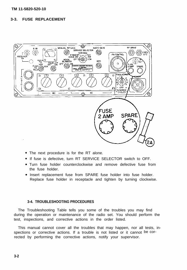
3-3. FUSE REPLACEMENT
●
●
●
●
The next procedure is for the RT alone.
If fuse is defective, turn RT SERVICE SELECTOR switch to OFF.
Turn fuse holder counterclockwise and remove defective fuse fromthe fuse holder.
Insert replacement fuse from SPARE fuse holder into fuse holder.Replace fuse holder in receptacle and tighten by turning clockwise.
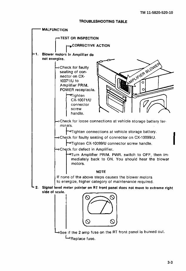
3-4. TROUBLESHOOTING PROCEDURES
The Troubleshooting Table tells you some of the troubles you may findduring the operation or maintenance of the radio set. You should perform thetest, inspections, and corrective actions in the order listed.
This manual cannot cover all the troubles that may happen, nor all tests, in-spections or corrective actions. If a trouble is not listed or it cannotrected by performing the corrective actions, notify your supervisor.
be cor-
3-2
TM 11-5820-520-10
3-3
TM 11-5820-520-10
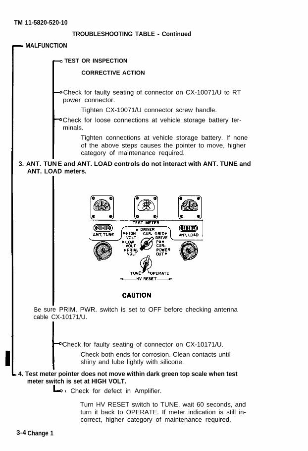
TROUBLESHOOTING TABLE - Continued
MALFUNCTION
3. ANT. TUN
TEST OR INSPECTION
CORRECTIVE ACTION
Check for faulty seating of connector on CX-10071/U to RTpower connector.
Tighten CX-10071/U connector screw handle.
Check for loose connections at vehicle storage battery ter-minals.
Tighten connections at vehicle storage battery. If noneof the above steps causes the pointer to move, highercategory of maintenance required.
E and ANT. LOAD controls do not interact with ANT. TUNE andANT. LOAD meters.
Be sure PRIM. PWR. switch is set to OFF before checking antennacable CX-10171/U.
Check for faulty seating of connector on CX-10171/U.
Check both ends for corrosion. Clean contacts untiIshiny and lube lightly with silicone.
4. Test meter pointer does not move within dark green top scale when testmeter switch is set at HIGH VOLT.
Check for defect in Amplifier.
Turn HV RESET switch to TUNE, wait 60 seconds, andturn it back to OPERATE. If meter indication is still in-correct, higher category of maintenance required.
3-4 Change 1
TM 11-5820-520-10
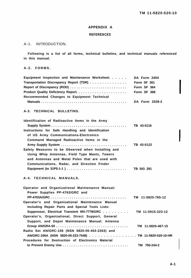
APPENDIX A
REFERENCES
A-1. INTRODUCTION.
Following is a list of all forms, technical bulletins, and technical manuals referencedin this manual.
A - 2 . F O R M S .
Equipment Inspection and Maintenance Worksheet. . . . . .
Transportation Discrepancy Report (TDR) . . . . . . . . . . . . . . .Report of Discrepancy (ROD) . . . . . . . . . . . . . . . . . . . . . . . . . .
Product Quality Deficiency Report. . . . . . . . . . . . . . . . . . . . . .
Recommended Changes to Equipment Technical
Manuals . . . . . . . . . . . . . . . . . . . . . . . . . . . . . . . . . . . . . . . . . .
A-3. TECHNICAL BULLETINS.
Identification of Radioactive Items in the Army
Supply System . . . . . . . . . . . . . . . . . . . . . . . . . . . . . . . . . . . . .
Instructions for Safe Handling and Identificationof US Army Communications-Electronics
Command Managed Radioactive Items in the
Army Supply System . . . . . . . . . . . . . . . . . . . . . . . . . . . . . . .
Safety Measures to be Observed when Installing andUsing Whip Antennas, Field Type Masts, Towers
and Antennas and Metal Poles that are used with
Communications, Radar, and Direction FinderEquipment (to 31P5-1-1 ) . . . . . . . . . . . . . . . . . . . . . . . . . . . .
A - 4 . T E C H N I C A L M A N U A L S .
Operator and Organizational Maintenance Manual:Power Supplies PP-4763/GRC and
PP-4763A/GRC . . . . . . . . . . . . . . . . . . . . . . . . . . . . . . . . . . . .
Operator’s and Organizational Maintenance ManualIncluding Repair Parts and Special Tools Lists:
Suppressor, Electrical Transient MX-7778/GRC . . . . . . . . .
DA Form 2404Form SF 361Form SF 364
Form SF 368
DA Form 2028-2
TB 43-0116
TB 43-0122
TB SIG 291
TM 11-5820-765-12
TM 11-5915-223-12Operator’s, Organizational, Direct Support, General
Support, and Depot Maintenance Manual: AntennaGroup AN/GRA-50 . . . . . . . . . . . . . . . . . . . . . . . . . . . . . . . . . . TM 11-5820-467-15
Radio Set AN/GRC-106 (NSN 5820-00-402-2263) and
AN/GRC-106A (NSN 5820-00-223-7548) . . . . . . . . . . . . . . . . TM 11-5820-520-10-HRProcedures for Destruction of Electronics Material
to Prevent Enemy Use . . . . . . . . . . . . . . . . . . . . . . . . . . . . . . . TM 750-244-2
A-1
TM 11-5820-520-10
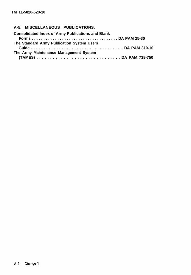
A-5. MISCELLANEOUS PUBLICATIONS.
Consolidated Index of Army Publications and BlankForms . . . . . . . . . . . . . . . . . . . . . . . . . . . . . . . . . . . . . DA PAM 25-30
The Standard Army Publication System UsersGuide . . . . . . . . . . . . . . . . . . . . . . . . . . . . . . . . . . . .. DA PAM 310-10
The Army Maintenance Management System(TAMES) . . . . . . . . . . . . . . . . . . . . . . . . . . . . . . . DA PAM 738-750
A-2
TM 11-5820-520-10
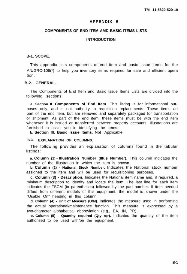
APPENDIX B
COMPONENTS OF END ITEM AMD BASIC ITEMS LISTS
INTRODUCTION
B-1. SCOPE.
This appendix lists components of end item and basic issue items for the
AN/GRC-106(*) to help you inventory items required for safe and efficient operation.
B-2. GENERAL.
The Components of End Item and Basic Issue Items Lists are divided into thefollowing sections:
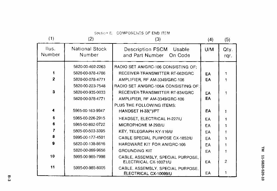
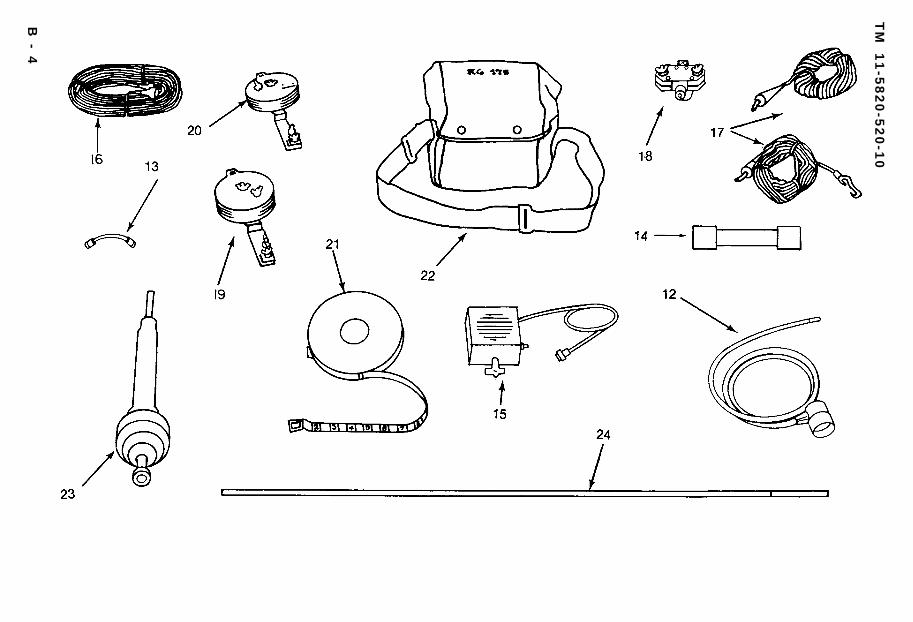
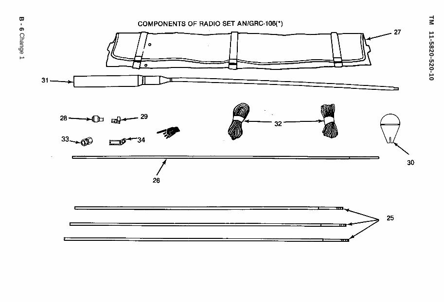
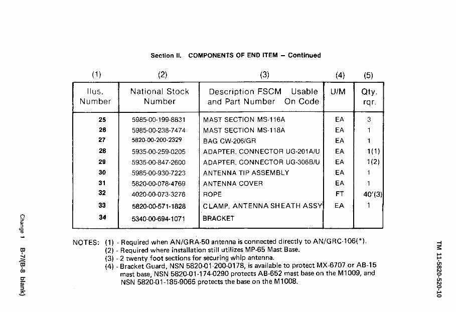
a. Section Il. Components of End Item. This listing is for informational pur-poses only, and is not authority to requisition replacements. These items artpart of the end item, but are removed and separately packaged for transportationor shipment. As part of the end item, these items must be with the end itemwhenever it is issued or transferred between property accounts. Illustrations arefurnished to assist you in identifying the items.
b. Section Ill. Basic Issue Items. Not Applicable.
B-3. EXPLANATION OF COLUMNS.
The following provides an explanation of columns found in the tabularlistings:
a. Column (1) - Illustration Number (Illus Number). This column indicates thenumber of the illustration in which the item is shown.
b. Column (2) - National Stock Number. Indicates the National stock numberassigned to the item and will be used for requisitioning purposes.
c. Column (3) - Description. Indicates the National item name and, if required, aminimum description to identify and locate the item. The last line for each itemindicates the FSCM (in parentheses) followed by the part number. If item neededdiffers from different models of this equipment, the model is shown under the“Usable On” heading in this column.
d. Column (4) - Unit of Measure (U/M). Indicates the measure used in performingthe actual operational/maintenance function. This measure is expressed by atwo-character alphabetical abbreviation (e.g., EA, IN, PR).
e. Column (5) - Quantity required (Qty rqr). Indicates the quantity of the itemauthorized to be used with/on the equipment.
B-1

TM
1
1-5
82
0-5
20
-10
B-2
Section II.
Section II.
TM
11-5820-520-10
B-3
TM
1
1-5
82
0-5
20
-10
B-
4

Section II.
Section II.
TM
11-5820-520-10
B-
5
TM
1
1-5
82
0-5
20
-10
B-
6C
hange 1
Section II.
TM 11-5820-520-10
B-7/(B
-8 blan
k)


TM 11-5820-520-10
GLOSSARY
Deflection . . . . . . . . . . . . . . . . . . . . . . . .
Disable . . . . . . . . . . . . . . . . . . . . . . . . . .
Indicate . . . . . . . . . . . . . . . . . . . . . . . . .
Interference . . . . . . . . . . . . . . . . . . . . . .
Keying . . . . . . . . . . . . . . . . . . . . . . . . . .
Radiate . . . . . . . . . . . . . . . . . . . . . . . . . .
Receptacle . . . . . . . . . . . . . . . . . . . . . . .
The movement of an indicator or pointerfrom the zero reading on a meter.
Prevent from working.
Point out or show.
Reception of straysignals.
or unwanted radio
Activating an electronic circuit.
To send out from a center.
A mounted electrical fittingthe live parts of a circuit.
containing
Glossary-1/(Glossary-2 blank)

TM 11-5820-520-10
I N D E X
SUBJECT PAGE
A
Abbreviations . . . . . . . . . . . . . . . . . . . . . . . . . . . . . . . . . . . . . . . . . . . . . 1-2Amplifier AM-3349/GRC-106 . . . . . . . . . . . . . . . . . . . . . . . . . . . . . . . . . 2-10Antenna description . . . . . . . . . . . . . . . . . . . . . . . . . . . . . . . . . . . . . . . 1-4Antenna tuning . . . . . . . . . . . . . . . . . . . . . . . . . . . . . . . . . . . . . . . . ...2-34Antijamming procedures . . . . . . . . . . . . . . . . . . . . . . . . . . . . . . . . ...2-47Assembly and preparation for use . . . . . . . . . . . . . . . . . . . . . . . . . . . . 2-21
c
Cleaning . . . . . . . . . . . . . . . . . . . . . . . . . . . . . . . . . . . . . . . . . . . . . . ...3-1Components . . . . . . . . . . . . . . . . . . . . . . . . . . . . . . . . . . . . . . . . . . . . . . 1-3Controls and indicators . . . . . . . . . . . . . . . . . . . . . . . . . . . . . . . . . . ...2-1
D
Description and use of operator’s controls and indicators . . . . . . . . 2-1Description of antenna . . . . . . . . . . . . . . . . . . . . . . . . . . . . . . . . . . . . . 1-4Destruction to prevent enemy use . . . . . . . . . . . . . . . . . . . . . . . . . . . . 2-48Differences between models. . . . . . . . . . . . . . . . . . . . . . . . . . . . . . . . 1-5
E
Emergency stopping procedure . . . . . . . . . . . . . . . . . . . . . . . . . . . . . . 2-44Equipment description . . . . . . . . . . . . . . . . . . . . . . . . . . . . . . . . . . . . . 1-3Equipment purpose, capabilities, and features . . . . . . . . . . . . . . . . . 1-3
F
Forms, maintenance . . . . . . . . . . . . . . . . . . . . . . . . . . . . . . . . . . . . . . . 1-1Fuse replacement . . . . . . . . . . . . . . . . . . . . . . . . . . . . . . . . . . , . . . ...3-2
G
Grounding . . . . . . . . . . . . . . . . . . . . . . . . . . . . . . . . . . . . . . . . . . . . . . . . 2-24
H
Hand receipt . . . . . . . . . . . . . . . . . . . . . . . . . . . . . . . . . . . . . . . . . . . . . . 1-2
Index-1
TM 11-5820-520-10
INDEX - Continued
SUBJECT PAGE
J
Jamming, radio . . . . . . . . . . . . . . . . . . . . . . . . . . . . . . . . . . . . . . . . 2-46
M
MaintenanceForms . . . . . . . . . . . . . . . . . . . . . . . . . . . . . . . . . . . . . . . . . . . . . . . . . 1-1General . . . . . . . . . . . . . . . . . . . . . . . . . . . . . . . . . . . . . . . . . . . . . . 3-1Instructions . . . . . . . . . . . . . . . . . . . . . . . . . . . . . . . . . . . . . . . . . . . .3-0
Major components, description . . . . . . . . . . . . . . . . . . . . . . . . . . . . . . 1-3Model differences . . . . . . . . . . . . . . . . . . . . . . . . . . . . . . . . . . . . . . . . . 1-5Mounting procedure . . . . . . . . . . . . . . . . . . . . . . . . . . . . . . . . . . . . 2-21Movement, preparation for . . . . . . . . . . . . . . . . . . . . . . . . . . . . . . . 2-45
N
Nomenclature, cross-reference list . . . . . . . . . . . . . . . . . . . . . . . . . . . 1-2
0
Operating instructions . . . . . . . . . . . . . . . . . . . . . . . . . . . . . . . . . . . . . 2-1Operating procedure . . . . . . . . . . . . . . . . . . . . . . . . . . . . . . . . . . . . . ..2-40Operation under unusual conditions . . . . . . . . . . . . . . . . . . . . . . . . . . 2-46Operation under usual conditions . . . . . . . . . . . . . . . . . . . . . . . . . . . . 2-21
P
Performance data . . . . . . . . . . . . . . . . . . . . . . . . . . . . . . . . . . . . . . . . . 1-7Preparation for movement . . . . . . . . . . . . . . . . . . . . . . . . . . . . . . . . ..2-45Preparation for use . . . . . . . . . . . . . . . . . . . . . . . . . . . . . . . . . . . . . ...2-21Preventive maintenance (PMCS). . . . . . . . . . . . . . . . . . . . . . . . . . . . . 2-16
Principles of operation, technical . . . . . . . . . . . . . . . . . . . . . . . . . . . . 1-9
R
Radio jamming . . . . . . . . . . . . . . . . . . . . . . . . . . . . . . . . . . . . . . . . . 2-46Records, maintenance . . . . . . . . . . . . . . . . . . . . . . . . . . . . . . . . . . 1-1Replacement, fuses . . . . . . . . . . . . . . . . . . . . . . . . . . . . . . . . . . . . . 3-2Reporting, equipment improvement recommendations . . . . . . . . . . 1-1Routine checks . . . . . . . . . . . . . . . . . . . . . . . . . . . . . . . . . . . . . . . . . 2-16RT-662/GRC . . . . . . . . . . . . . . . . . . . . . . . . . . . . . . . . . . . . . . . . . . . . . . 2-1RT-834/GRC . . . . . . . . . . . . . . . . . . . . . . . . . . . . . . . . . . . . . . . . . . . 2-2
index-2

TM 11-5820-520-10
INDEX - Continued
s
Starting procedure . . . . . . . . . . . . . . . . . . . . . . . . . . . . . . . . . . . . . . . . .Stopping procedure . . . . . . . . . . . . . . . . . . . . . . . . . . . . . . . . . . . . . . . .Stopping procedure, emergency . . . . . . . . . . . . . . . . . . . . . . . . . . . . .
T
Technical principles of operation . . . . . . . . . . . . . . . . . . . . . . . . . . . .To receive signals . . . . . . . . . . . . . . . . . . . . . . . . . . . . . . . . . . . . . . . . .To transmit signals . . . . . . . . . . . . . . . . . . . . . . . . . . . . . . . . . . . . . . . .Troubleshooting
Procedures . . . . . . . . . . . . . . . . . . . . . . . . . . . . . . . . . . . . . . . . . . . . .Table . . . . . . . . . . . . . . . . . . . . . . . . . . . . . . . . . . . . . . . . . . . . . . . . . .
Tuning procedure . . . . . . . . . . . . . . . . . . . . . . . . . . . . . . . . . . . . . . . .
PAGE
U
Unusual conditions, operation under . . . . . . . . . . . .Usual conditions, operation under . . . . . . . . . . . . . . . .
w
Warm up . . . . . . . . . . . . . . . . . . . . . . . . . . . . . . . . .
. . . .
. . . . . . . .
. . . .
. . .
. . . . . .
2-32
2-44
2-44
1-9
2-40
2-41
3-2
3-32-34
2-46
2-21
2-29
index-3/(index-4 blank)


By Order of the Secretary of the Army:
Official:
JOHN A. WICKHAM JR.General, United States Army
Chief of Staff
ROBERT M. JOYCEMajor General, United States Army
The Adjutant General
Distribution:
To be distributed in accordance with special list.


PIN : 052291-000