Embed Size (px)
Citation preview
TM 10-4320-316-14
TECHNICAL MANUALOPERATOR'S, UNIT,
DIRECT SUPPORT, AND GENERAL SUPPORTMAINTENANCE MANUAL
PUMP UNIT, CENTRIFUGAL,DIESEL ENGINE DRIVEN,
SELF PRIMING, 65 GPM WATERMODEL 4M SDQ 2000NSN 4320-01-338-8010
INTRODUCTION 1-1
OPERATINGINSTRUCTIONS 2-1
OPERATORMAINTENANCE 3-1
UNITMAINTENANCE 4-1
DIRECT SUPPORTMAINTENANCE 5-1
GENERAL SUPPORTMAINTENANCE 6-1
COMPONENTS OFEND ITEM LIST C-1
ALPHABETICAL INDEX
Distribution Statement A: Approved for public release; distribution i unlimited.HEADQUARTERS, DEPARTMENT OF THE ARMY
18 JANUARY 1994

TM 10-4320-316-14
WARNINGCARBON MONOXIDE (EXHAUST GAS) CAN KILL YOU
Carbon monoxide is without color or smell, but can kill you. Breathing air with carbon monoxideproduces symptoms of headache, dizziness, loss of muscular control, a sleepy feeling, and coma. Heavyexposure can cause brain damage or death. Carbon monoxide gas occurs in the exhaust fumes of internalcombustion engines, and can become dangerously concentrated under conditions of no air movement. Toensure your safety and that of other maintenance personnel, always observe the following precautions:
DO NOT operate engine in a closed place unless the place has a lot of moving air. Engine should be kept atleast five feet away from buildings and other equipment during operation.
DO NOT idle engine for long periods without proper ventilation.
BE ALERT at all times for exhaust odors and exposure symptoms. If either is present, IMMEDIATELYVENTILATE personnel compartments; remove affected crew to fresh air; keep warm; if necessary, giveartificial respiration. FOR ARTIFICIAL RESPIRATION REFER TO FM 21-11.
BE AWARE; the field protective mask for chemical-biological-radiological (CBR) protection will not protectyou against carbon monoxide poisoning.
THE BEST DEFENSE AGAINST CARBONMONOXIDE POISONING IS GOOD VENTILATION.
WARNINGMishandling fuel could result in death or serious injury. Engine must be turned off and cool before refueling. Use properrefueling procedures and equipment to avoid spillage. Wipe away fuel spills with a clean cloth. Refuel only in a well-ventilated area away from open flame, arcing equipment, ignition sources, heaters, or excessive heat. Do not run enginenear open fuel containers. Always store fuel in properly, marked containers. DO NOT SMOKE when refueling.
WARNINGTouching or handling heated parts will cause severe injury to operating personnel. Muffler and related components gethot enough during pump operation to cause severe burns. Avoid contact with muffler and related components duringrepair procedures described in this text. Do not perform any repair procedures until the unit has cooled down sufficiently.
WARNINGOperating engine without protective covers could result in serious injury. If any item becomes loose or cracked,immediately stop the engine and repair. After completing any "Remove, Replace, or Repair" procedures ensure thatprotective covers are reinstalled before operating the pump.
a

TM 10-4320-316-14WARNING
Misuse of compressed air could result in death or serious injury. Death or serious injury could occur if compressed air isdirected against skin. Do not use compressed air for cleaning or drying unless the pressure is/has been reduced to 30PSI or less. When working with compressed air, always use eye protection and any other protective equipment.
WARNINGLifting or moving heavy equipment can cause serious injury. Do not try to lift or move more than 50 pounds by yourself.Get an assistant. Bend legs while lifting. Don't support heavy equipment with your back.
Always use assistants during lifting operations. Use guide ropes to more hanging assemblies.
A lack of attention or being in an improper position during lifting operations can result in serious injury or death. Pay closeattention to movements of assemblies being lifted. Do not stand under lifted assembly or in a position where you couldbe pinned against another object. Watch your footingHoist used to lift pumping assembly must have a minimum lifting capacity of 750 pounds.
FIRST AIDRefer to FM 21-11 for first aid procedures.
b

TM 10-4320-316-14
TECHNICAL MANUAL HEADQUARTERSTM10-4320-316-14 DEPARTMENT OF THE ARMY
WASHINGTON, D.C., 18 January 1994
Operator's, Unit, Direct Support,and General Support Maintenance Manual
For
PUMP UNIT, CENTRIFUGAL, DIESEL ENGINE DRIVEN,SELF-PRIMING, 65 GPM WATER
MODEL 4M SDQ 2000NSN 4320-01-338-8010
REPORTING ERRORS AND RECOMMENDING IMPROVEMENTS
You can help improve this manual. If you find any mistakes or if you know of a way to improvethe procedures, please let us know. Mail your letter, DA Form 2028 (Recommended Changes toPublications and Blank Forms) or DA Form 2028-2 located in the back of this manual direct to:Commander, U. S. Army Aviation and Troop Command, ATTN: AMSAT-I-MP, 4300 GoodfellowBlvd. , St. Louis, MO. 63120-1798. A reply will be furnished to you.
TABLE OF CONTENTSPage
How To Use This Manual.......................................................................................................................... vii
CHAPTER 1. INTRODUCTION ................................... ......................................................................... 1-1
Section I. General Information .................................. ........................................................................ 1-1Section II. Equipment Description and Data ........................ ............................................................... 1-2Section III. Principles of Operation ...................................................................................................... 1-5
CHAPTER 2. OPERATING INSTRUCTIONS .......................................................................................... 2-1
Section I. Description and Use of Operator'sControls and Indicators.................................................................................................. 2-2
Section II. Operator Preventive Maintenance Checks andServices ........................................................................................................................ 2-4
DISTRIBUTION STATEMENT A: Approved for public release; distribution is unlimited
i

TM 10-4320-316-14
TABLE OF CONTENTS - Continued
Page
Section III. Operation Under Usual Conditions .................................................................................... 2-12Section IV. Operation Under Unusual Conditions ................ ................................................................ 2-20
CHAPTER 3. OPERATOR MAINTENANCE INSTRUCTIONS ................................................................ 3-1
Section I. Lubrication Instructions ................................ ..................................................................... 3-1Section II. Operator Troubleshooting Procedures .................. ............................................................ 3-1Section III. Operator Maintenance Procedures .............. ...................................................................... 3-5
CHAPTER 4. UNIT MAINTENANCE INSTRUCTIONS ........................................................................... 4-1
Section I. Repair Parts, Special Tools; Test, Measurement,and Diagnostic Equipment, and Support Equipment........................................................... 4-1
Section II. Service Upon Receipt and Preparation for Movement ........................................................ 4-1Section III. Lubrication ........................................................................................................................ 4-4Section IV. Unit Preventive Maintenance Checks and Services (PMCS) .............................................. 4-5Section V. Unit Troubleshooting Procedures .................. .................................................................... 4-9Section VI. Unit Maintenance Procedures .... ....................................................................................... 4-15Section VII. Preparation for Storage or Shipment .................................................................................. 4-84
CHAPTER 5. DIRECT SUPPORT MAINTENANCE INSTRUCTIONS ..................................................... 5-1
Section I. Repair Parts, Special Tools; Test, Measurement,and Diagnostic Equipment (TMDE), and Support Equipment ........................................ 5-1
Section II. Direct Support Troubleshooting Procedures ...................................................................... 5-1Section III. Direct Support Maintenance Procedures ............................................................................ 5-3
CHAPTER 6. GENERAL SUPPORT MAINTENANCE INSTRUCTIONS ................................................. 6-1
Section I. Repair Parts, Special Tools; Test, Measurement,and Diagnostic Equipment, and Support Equipment ...................................................... 6-1
Section II. General Support Maintenance Procedures ......................................................................... 6-1
APPENDIX A. REFERENCES .................................................................................................................. A-1
APPENDIX B. MAINTENANCE ALLOCATION CHART............................................................................ B-1
Section I. Introduction ...................................................................................................................... B-1Section II. Maintenance Allocation Chart ............................................................................................ B-5Section III. Special Tool and Test Equipment Requirements ............... ................................................ B-9Section IV. Remarks ........................................... ................................................................................ B-10
ii

TM 10-4320-316-14
TABLE OF CONTENTSPage
APPENDIX C. COMPONENTS OF END ITEM AND BASICISSUE ITEMS LIST ............................................................ C-1
Section I. Introduction ........................................ .......................................................................... C-1Section II. Components of End Item Table ......................................................................................... C-2Section Ill. Basic Issue Item Table ................................. ..................................................................... C-4
APPENDIX D. ADDITIONAL AUTHORIZATION LIST .............................................................................. D-1
Section I. Introduction ....................................... ................................................................................ D-1Section II. Additional Authorization List ........................... ................................................................... D-2
APPENDIX E. EXPENDABLE/DURABLE SUPPLIESAND MATERIALS LIST..................................................................................................... E-1
Section I. Introduction ........................................................................................................................ E-1Section II. Expendable/Durable Supplies and Materials List ............... ................................................ E-2
APPENDIX F. ILLUSTRATED LIST OF MANUFACTURED PARTS ........... ........................................... F-1
APPENDIX G. TORQUE LIMITS .............................................................................................................. G-1
ALPHABETICAL INDEX............................................................................................................................. Index-1
iii
TM 10-4320-316-14
LIST OF ILLUSTRATIONS
Figure No. Title Page
1-1 Pump Unit, Centrifugal, Diesel Engine-Driven, Self-Priming, 65 GPM ...... ......................................1-01-2 Location of Major Components ................................ .......................................................................1-32-1 Operator's Controls and Indicators ...................................................................................................2-32-2 Operator PMCS Routing Diagram ...................................................................................................2-82-3 Priming Pump .............................................. ..................................................................................2-122-4 Refueling DED Pump Assembly ................... ...................................................................................2-142-5 Starting and Operating the DED Pump Assembly .................. ..........................................................2-162-6 Decals and Instruction Plates ...........................................................................................................2-182-7 Cold Weather Starting Aid ...................................... .........................................................................2-213-1 Servicing Fuel Inlet Filter .................................................................................................................3-53-2 Servicing Air Cleaner Element .........................................................................................................3-64-1 Ident Plates Replacement ................................................................................................................4-174-2 Roll-Over Frame Replacement ................................... .....................................................................4-194-3 Compression Release Handle Replacement ................. ..................................................................4-214-4 Control Assembly Replacement .......................................................................................................4-234-5 Air Intake Hose Replacement .................................... ......................................................................4-254-6 Exhaust Extension Replacement .................................. ...................................................................4-274-7 Access Cover Repair and Replacement ...........................................................................................4-294-8 Pump Drain Repair and Replacement ..............................................................................................4-314-9 Oil Drain Repair and Replacement .... ..............................................................................................4-334-10 Baffles Replacement ...................................... .................................................................................4-354-11 Enclosure Assembly, Inlet Side Removal ........................... .............................................................4-394-12 Enclosure Assembly, Inlet Side Disassembly ...................................................................................4-404-13 Enclosure Assembly, Outlet Side Removal .....................................................................................4-434-14 Enclosure Assembly, Outlet Side Disassembly ..................... ...........................................................4-444-15 Pump Inlet/Outlet Piping Repair and Suction Flange Repair
and Replacement ........................................................................................................................4-474-16 Bottom Pan Frame Repair and Replacement....................................................................................4-514-17 Pump Assembly Repair and Replacement .......................................................................................4-554-18 Measuring Impeller Clearance .................................. .......................................................................4-574-19 Fuel Tank Assembly Repair and Replacement ...................... ..........................................................4-614-20 Fuel Filter, Inlet Replacement .........................................................................................................4-654-21 Fuel Cock and Fuel Filter, Outlet Replacement ...................... ........................................................4-674-22 Fuel Lines Replacement ...................................... ............................................................................4-694-23 Air Cleaner, Filter Element, and Air Intake Pipe Repair and Replacement .... ...................................4-714-24 Exhaust Silencer Replacement ........................................................................................................4-734-25 Recoil Starter and Fan Cooling Case Repair and Replacement ........... ............................................4-754-26 Fuel Injector Pump Replacement ....................................................................................................4-794-27 Fuel Injector Pump Alignment ................................... ......................................................................4-794-28 Lube Oil Strainer Repair and Replacement .....................................................................................4-814-29 Oil Cap/Gauge Repair and Replacement..........................................................................................4-83
iv

TM 10-4320-316-14
LIST OF ILLUSTRATIONS
Figure No. Title Page
5-1 Mounting Plate Repair and Replacement .........................................................................................5-55-2 Fuel Injector Valve Assembly Replacement .....................................................................................5-75-3 Regulator Bracket Assembly Repair and Replacement .................. ..................................................5-115-4 Cylinder Head Removal....................................................................................................................5-155-5 Cylinder Head Disassembly..............................................................................................................5-175-6 Valve Recess . .................................................................................................................................5-185-7 Spring Inclination .............................................................................................................................5-185-8 Alignment of Flywheel With Cylinder Block ......................................................................................5-215-9 Adjusting Valve Clearance ...............................................................................................................5-215-10 Flywheel Replacement ....................................................................................................................5-236-1 Crankcase Cover Replacement ........................................................................................................6-36-2 Main Bearing Insert Removal ...........................................................................................................6-46-3 Tightening Sequence for Crankcase Cover Bolts..............................................................................6-56-4 Piston and Connecting Rod Assembly Replacement ........................................................................6-76-5 Governor Assembly Removal ..........................................................................................................6-136-6 Lube Oil Pump Repair and Replacement..........................................................................................6-146-7 Lube Oil Pump Installation ...............................................................................................................6-146-8 Balancer Shaft Removal...................................................................................................................6-176-9 Rotating Group Timing Marks...........................................................................................................6-296-10 Camshaft Removal...........................................................................................................................6-196-11 Rotating Group Timing Marks...........................................................................................................6-196-12 Crankshaft Assembly Replacement ..................................................................................................6-21
v
TM 10-4320-316-14
LIST OF TABLESFigure No. Title Page
1-1 Equipment Data ...............................................................................................................................1-42-1 Preventive Maintenance Checks and Services ......................... .......................................................2-63-1 Operator Troubleshooting .................................................................................................................3-24-1 Unit Preventive Maintenance Checks and Services..........................................................................4-64-2 Troubleshooting by Exhaust Color ............................... ....................................................................4-94-3 Unit Troubleshooting ........................................ ..............................................................................4-115-1 Direct Support Troubleshooting Chart ............................. .................................................................5-2
vi
TM 10-4320-316-14
HOW TO USE THIS MANUAL
GENERAL. This technical manual provides you with the information needed to operate and to maintain the DED PumpAssembly. By properly using this manual, you will be able to identify any problem you may have in operating the pumpassembly and then locate the proper procedure needed to correct any problem found.
MANUAL ORGANIZATION. This manual has been organized in a manner that groups together the information that anoperator or a maintenance technician will need to perform their duties. The following list indicates how this informationhas been organized.
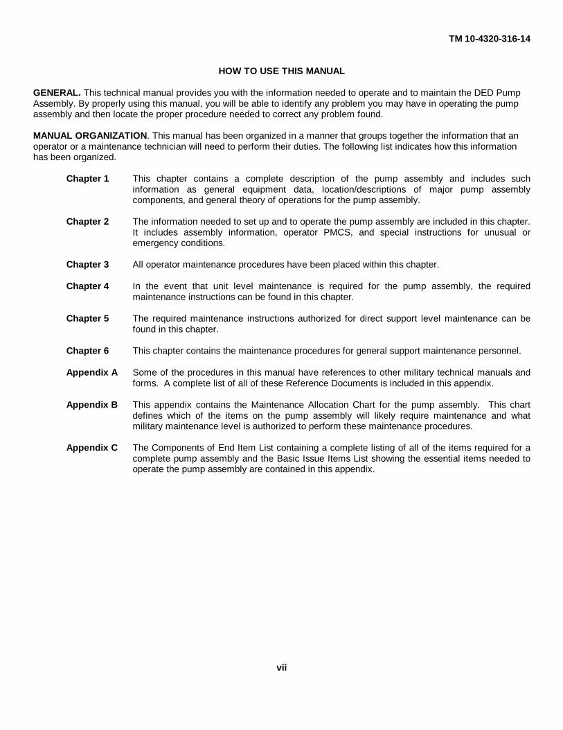
Chapter 1 This chapter contains a complete description of the pump assembly and includes suchinformation as general equipment data, location/descriptions of major pump assemblycomponents, and general theory of operations for the pump assembly.
Chapter 2 The information needed to set up and to operate the pump assembly are included in this chapter.It includes assembly information, operator PMCS, and special instructions for unusual oremergency conditions.
Chapter 3 All operator maintenance procedures have been placed within this chapter.
Chapter 4 In the event that unit level maintenance is required for the pump assembly, the requiredmaintenance instructions can be found in this chapter.
Chapter 5 The required maintenance instructions authorized for direct support level maintenance can befound in this chapter.
Chapter 6 This chapter contains the maintenance procedures for general support maintenance personnel.
Appendix A Some of the procedures in this manual have references to other military technical manuals andforms. A complete list of all of these Reference Documents is included in this appendix.
Appendix B This appendix contains the Maintenance Allocation Chart for the pump assembly. This chartdefines which of the items on the pump assembly will likely require maintenance and whatmilitary maintenance level is authorized to perform these maintenance procedures.
Appendix C The Components of End Item List containing a complete listing of all of the items required for acomplete pump assembly and the Basic Issue Items List showing the essential items needed tooperate the pump assembly are contained in this appendix.
vii
TM 10-4320-316-14
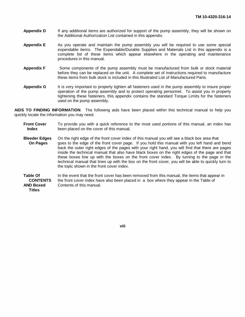
Appendix D If any additional items are authorized for support of the pump assembly, they will be shown onthe Additional Authorization List contained in this appendix.
Appendix E As you operate and maintain the pump assembly you will be required to use some specialexpendable items. The Expendable/Durable Supplies and Materials List in this appendix is acomplete list of these items which appear elsewhere in the operating and maintenanceprocedures in this manual.
Appendix F Some components of the pump assembly must be manufactured from bulk or stock materialbefore they can be replaced on the unit. A complete set of instructions required to manufacturethese items from bulk stock is included in this Illustrated List of Manufactured Parts.
Appendix G It is very important to properly tighten all fasteners used in the pump assembly to insure properoperation of the pump assembly and to protect operating personnel. To assist you in properlytightening these fasteners, this appendix contains the standard Torque Limits for the fastenersused on the pump assembly.
AIDS TO FINDING INFORMATION. The following aids have been placed within this technical manual to help youquickly locate the information you may need.
Front Cover To provide you with a quick reference to the most used portions of this manual, an index hasIndex been placed on the cover of this manual.
Bleeder Edges On the right edge of the front cover index of this manual you will see a black box area thatOn Pages goes to the edge of the front cover page. If you hold this manual with you left hand and bend
back the outer right edges of the pages with your right hand, you will find that there are pagesinside the technical manual that also have black boxes on the right edges of the page and thatthese boxes line up with the boxes on the front cover index. By turning to the page in thetechnical manual that lines up with the box on the front cover, you will be able to quickly turn tothe topic shown in the front cover index.
Table Of In the event that the front cover has been removed from this manual, the items that appear in CONTENTS the front cover index have also been placed in a box where they appear in the Table of
AND Boxed Contents of this manual.Titles
viii
TM 10-4320-316-14
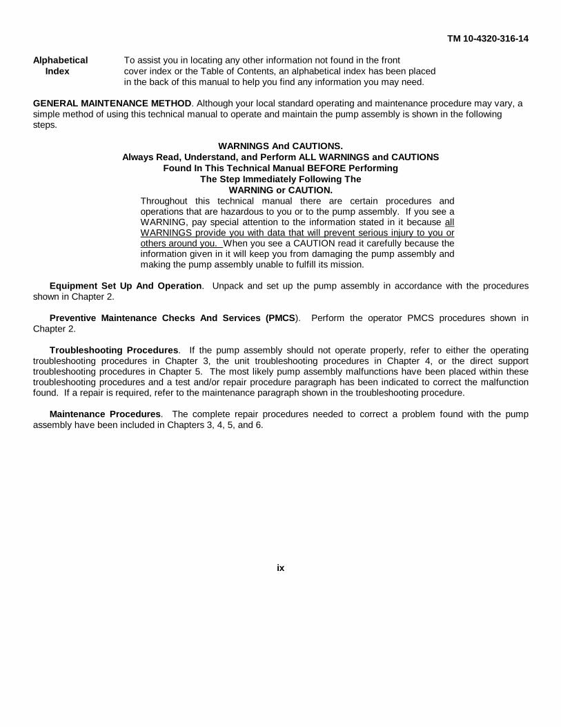
Alphabetical To assist you in locating any other information not found in the frontIndex cover index or the Table of Contents, an alphabetical index has been placed
in the back of this manual to help you find any information you may need.
GENERAL MAINTENANCE METHOD. Although your local standard operating and maintenance procedure may vary, asimple method of using this technical manual to operate and maintain the pump assembly is shown in the followingsteps.
WARNINGS And CAUTIONS.Always Read, Understand, and Perform ALL WARNINGS and CAUTIONS
Found In This Technical Manual BEFORE PerformingThe Step Immediately Following The
WARNING or CAUTION.Throughout this technical manual there are certain procedures andoperations that are hazardous to you or to the pump assembly. If you see aWARNING, pay special attention to the information stated in it because allWARNINGS provide you with data that will prevent serious injury to you orothers around you. When you see a CAUTION read it carefully because theinformation given in it will keep you from damaging the pump assembly andmaking the pump assembly unable to fulfill its mission.
Equipment Set Up And Operation. Unpack and set up the pump assembly in accordance with the proceduresshown in Chapter 2.
Preventive Maintenance Checks And Services (PMCS). Perform the operator PMCS procedures shown inChapter 2.
Troubleshooting Procedures. If the pump assembly should not operate properly, refer to either the operatingtroubleshooting procedures in Chapter 3, the unit troubleshooting procedures in Chapter 4, or the direct supporttroubleshooting procedures in Chapter 5. The most likely pump assembly malfunctions have been placed within thesetroubleshooting procedures and a test and/or repair procedure paragraph has been indicated to correct the malfunctionfound. If a repair is required, refer to the maintenance paragraph shown in the troubleshooting procedure.
Maintenance Procedures. The complete repair procedures needed to correct a problem found with the pumpassembly have been included in Chapters 3, 4, 5, and 6.
ix

TM 10-4320-316-14
Figure 1-1. Pump Unit, Centrifugal, Diesel Engine Driven,Self-Priming, 65 GPM.
1-0

TM 10-4320-316-14
CHAPTER 1
INTRODUCTION
SECTION I. GENERAL INFORMATION
1-1. SCOPE.
a. Type of Manual. Operator's, Unit, Direct Support, and General Support Maintenance Manual
b. Model Number and Equipment Name. Model 4M SDQ 2000 Pump Unit, Centrifugal, Diesel Engine Driven(DED), Self-Priming, 65 GPM.
c. Purpose of Equipment. The pump unit covered by this manual is intended for use in pumping water to and fromvarious water storage and distribution systems.
1-2. MAINTENANCE FORMS AND PROCEDURES. Department of the Army forms and procedures used for equipmentmaintenance will be those prescribed by DA PAM 738-750. The Army Maintenance Management System (TAMMS)(Maintenance Management UPDATE).
1-3. CORROSION AND PREVENTION CONTROL. Corrosion Prevention and Control (CPC) of Army materiel is acontinuing concern. It is important that any corrosion problems with this item be reported so that the problem can becorrected and improvements can be made to prevent the problem in future items.
While corrosion is typically associated with the rusting of metals, it can also include deterioration of other materials suchas rubber and plastic. Unusual cracking, softening, swelling, or breaking of the materials may be a corrosion problem.
If a corrosion problem is identified, it can be reported using Standard Form 368, Product Quality Deficiency Report. Useof key words such as "rust", "deterioration", "corrosion", or "cracking" will insure that the information is identified as aCPC problem. The form should be submitted to the address specified in the DA PAM 738-750.
1-4. DESTRUCTION OF ARMY MATERIEL TO PREVENT ENEMY USE. Refer to TM 750-244-3, Procedures forDestruction of Equipment to Prevent Enemy Use.
1-5. PREPARATION FOR STORAGE OR SHIPMENT. Contact unit maintenance for preparation and storage orshipment. Refer to Section VI, Chapter 4.
1-6. REPORTING EQUIPMENT IMPROVEMENT RECOMMENDATIONS (EIR'S). If your pump assembly needsimprovement, let us know. Send us an EIR. You, the user, are the only one who can tell us what you don't like aboutyour equipment. Let us know why you don't like the design or performance. Put it on a SF 368 (Product QualityDeficiency Report). Mail it to us at;
CommanderU.S. Army Aviation and Troop Support CommandAttention: AMSAT-I-MDO4300 Goodfellow Blvd.St. Louis, Missouri 63120-1798.
We will send you a reply.
1-1

TM 10-4320-316-14
1-7. NOMENCLATURE CROSS-REFERENCE LIST. To simplify the use of certain terms used in this technical manual,some common names have been used to replace longer or more complex terms. The following list shows the commonname used in this technical manual and the official nomenclature of the terms these common names replace.
Common Name Official NomenclatureDED pump assembly Pump Unit, Centrifugal, Diesel Engine Driven,
or pump assembly Self-Priming, 65 GPM Water
1-8. LIST OF ABBREVIATIONS. All abbreviations use within this technical manual conform to the standard militaryabbreviations found in MIL-STD-12, Abbreviations for Use on Drawings, and in Specifications, Standards, and TechnicalDocuments.
SECTION II. EQUIPMENT DESCRIPTION
1-9. EQUIPMENT CHARACTERISTICS, CAPABILITIES, AND FEATURES.
a. Characteristics and Capabilities. The 'DED pump assembly is designed to pump water and has the followingcharacteristics and capabilities.
(1) Self contained diesel engine driven unit.
(2) The pump and engine assembly are enclosed within an enclosure assembly which has been specially designed toreduce the amount of noise emitted from the DED pump assembly during pumping operations.
(3) The DED pump assembly is capable of pumping 65 gallons per minute of water at not more than a 50 foot headand not more than a 10 foot static suction lift.
b. Features. The DED pump assembly has the following features.
(1) The diesel engine is equipped with a manual recoil type starter.
(2) The enclosure assembly is equipped with a roll-over frame mounted onto the enclosure to provide an easier andmore stable way of manually moving the DED pump assembly to various operating sites. These handles also actas a roll cage to protect the unit in the event the unit should roll over.
(3) A throttle control on the engine allows for varying the speed of the engine to control the pumping rate of the DEDpump assembly.
(4) After the pump has been initially primed, it is capable of being stopped and restarted without the need of furtherpriming.
1-10. LOCATION AND DESCRIPTION OF MAJOR COMPONENTS. The following major components of the DEDpump assembly are described below and are located as shown on Figure 1-2.
a. Diesel Engine Assembly. A 3. 8 horsepower diesel engine (1) is provided to drive the pump.
b. Pump. A self-priming pump (2) is attached to the diesel engine assembly. This centrifugal type pump uses animpeller to provide the pumping capability of the DED pump assembly.
1-2

TM 10-4320-316-14
c. Bottom Pan Frame. All of the above items are mounted and assembled to a lower bottom pan frame (4). Thisbottom pan frame is equipped with a roll-over frame (5) to allow easier movement of the DED pump assembly to otherlocations.
d. Sound Enclosure Assembly. Because the normal operation of the diesel engine can be quite noisy, a soundenclosure (3) surrounds the pump and diesel engine to reduce the amount of noise transmitted to the operator. Thisenclosure is equipped with an operator access door for use in starting, operating, and servicing of the unit.
Figure 1-2. Location of Motor Components.1-3

TM 10-4320-316-14
1-11. EQUIPMENT DATA. Refer to Table 1-1. for general equipment and performance data for the DED pumpassembly.
Table 1-1. Equipment Data.
PUMPManufacturer ........................ ................................................................ E. C. Schleyer Pump Company, Inc.Service ............. .................................................................................................................................. WaterDuty Cycle .................................................................................................................................. ContinuousRated Output ....................................................................................................... 65 GPM at 50 ft total headSuction (Intake) Port .................................................................................................................. 1.50 in. NPTDischarge Port .................................... ...................................................................................... 1.50 in. NPTPriming Method ......................... ...................................................................... Self-priming after initial fillingDrain Port .................................................................................................................................... 3/8 in. NPTRotation ......................... ......................................................................Counterclockwise (facing pump side)
ENGINEManufacturer ....................................... ..............................................................................................YanmarModel .................................................. ............................................................................................L40AE-DHorsepower ..............................................................................................................................................3.8Type ........................................................................................Four-stroke, forced air cooled by flywheel fanNumber of Cylinders ............................................................................................................................... OneBore .............................................. .................................................................................... 2.677 in. (68 mm)Stroke ............................................. .................................................................................. 2.165 in. (55 mm)Displacement .................................. .........................................................................12.14 cu in. (0.199 liter)Compression Ratio (nominal) .................................. ........................................................................ 20.5 to 1Direction of Rotation ...............................................................................Counterclockwise (facing shaft end)Number of Main Bearings ....................................................................................................................... Two
AIR CLEANERManufacturer ........................................ .............................................................................................YanmarType ............................................................................................................ Dry type, paper cleaner element
CAPACITIESFuel Tank ..................................... ............................................................................... 0.92 gallon (3.5 liters)Engine Crankcase ................................. ....................................................................... 0.79 quart (0.75 liter)
DIMENSIONS AND WEIGHTOverall Width ....................................................................................................................27.37 in (69.5 cm)Overall Length ...................................................................................................................23.94 in (60.8 cm)Overall Height .................................... ...............................................................................24.33 in (61.8 cm)Gross Weight ..................................... ............................................................................202.00 lb (91.82 kg)Shipping Volume ........................ .................................................................9.2 cubic feet (0.26 cubic meter)
1-4

TM 10-4320-316-14
SECTION III. PRINCIPLES OF OPERATION
1-12. THEORY OF OPERATIONS. The DED pump assembly is a self contained, transportable, diesel engine drivencentrifugal pump unit designed for pumping water. It consists of a self-priming pump, a four stroke air cooled dieselengine, and a sound enclosure for noise reduction. The pump assembly performs its pumping operations in the followingmanner (Refer to Figure 1-2).
a. Pumping Capability. The pumping capability of the DED pump assembly is provided by the pump unit containedwithin the assembly. This pump is a centrifugal type pump which means that it provides its pumping action by using aninternal rotating impeller to sling the water from the center of the impeller to the outer edges of the impeller as it rotates.This throwing action, technically known as centrifugal force, causes a vacuum in the inlet pipe of the pump to draw morewater into the pump. The water which has been forced to the outer edges of the impeller are further forced into the outletpipe of the pump to eventually leave the pump unit.
b. Diesel Engine. To cause the impeller inside the pump to rotate, the impeller shaft is connected to the output shaftof a diesel engine. This diesel engine is equipped with a manual recoil starter for starting the engine and a throttlecontrol assembly to control the engine speed. When the maximum rated capacity of 65 GPM is required of the pumpassembly, this throttle control is set to maximum to cause the engine to rotate at maximum rpm. When a pumping rateless that 65 GPM is required of the pump assembly, the diesel engine throttle control is adjusted to reduce the enginerpm until the lower rate of water to be pumped by the unit is achieved.
1-5/(1-6 Blank)

TM 10-4320-316-14
CHAPTER 2
OPERATING INSTRUCTIONS
CHAPTER 2 INDEX
Section I. Description and Use of Operator's Controlsand Indicators.....................................................................................2-2
2-1. Introduction ...............................................................................................2-22-2. Operator's Controls and Indicators .............. ...............................................2-2
Section II. Operator Preventive Maintenance Checksand Services (PMCS) .........................................................................2-4
2-3. General ................................. ....................................................................2-42-4. PMCS Procedures ................... .................................................................2-42-5. Special Instructions ....................................................................................2-52-6. Leakage Definitions for Operator PMCS .......... ..........................................2-5
Section III. Operation Under Usual Conditions .........................................................2-12
2-7. Assembly and Preparation for Use .............................................................2-122-8. Initial Adjustments, Daily Checks, and Self Tests........................................2-152-9. Operating Procedures ................... .............................................................2-152-10. Preparation for Movement ............... .........................................................2-182-11. Decals and Instruction Plates......................................................................2-18
Section IV. Operation Under Unusual Conditions ..... ...............................................2-20
2-12. Operation Under Unusual Weather ............. ...............................................2-20a. Operation In Extreme Cold ..............................................................2-20b. Operation In Extreme Heat ..............................................................2-21c. Operation In Sandy or Dusty Areas ........ .........................................2-21d. Operation In Salt Water Areas ........... .............................................2-22
2-13. Emergency Procedures ................... ..........................................................2-222-14. Nuclear, Biological, and Chemical (NBC)
Decontamination Procedures................................................................2-22
2-1

TM 10-4320-316-14
SECTION I. DESCRIPTION AND USE OFOPERATOR'S CONTROLS AND INDICATORS
2-1. INTRODUCTION. The DED pump assembly is designed for operation in a wide range of climatic conditions.Operators must be aware of any peculiarities or operational limitations for their specific installation. Before setting upand operating this system, be sure that you have determined the type of terrain and climate in which you will use the unitand that you have assembled and serviced the system to match the existing needs.
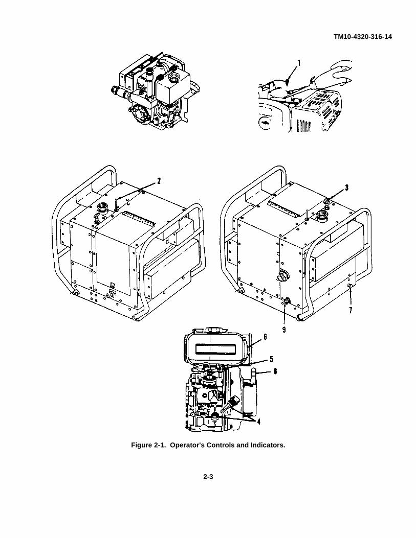
2-2. OPERATOR'S CONTROLS AND INDICATORS. For controls and indicators applicable to the DED pumpassembly, refer to the following descriptions and to Figure 2-1.
a. Cold Weather Plug (1). During DED pump assembly operation in colder weather, engine starting can be furtherhelped by removing the cold weather plug on the top of the engine rocker arm cover and adding 5 or 6 drops of engineoil. This reduces the additional friction cased by colder weather and makes the engine easier to start.
b. Decompression Handle (2). Because of the high internal cylinder pressure inside a diesel engine, it can bedifficult to start manually since the operator must overcome this internal pressure to start the engine rotation. To relievethis internal cylinder pressure for starting purposes, an engine decompression handle is furnished to vent the cylinderpressure and allow for easier engine starting.
c. Diesel Engine Throttle Control (3). After the diesel engine has been started, the engine speed can becontrolled by setting the engine throttle control.
d. Engine Oil Dipstick (4). To provide a method of checking for the correct amount of oil in the diesel engine, theengine is equipped with an engine oil dipstick. By removing this dipstick and checking the indicated oil level, properengine oil may be added as needed. Engine oil is added through the engine oil dipstick opening in the engine crankcase.
e. Fuel Cock (5). To control the flow of fuel from the fuel tank to the engine, a fuel cock is included to turn the fuelflow off or on.
f. Fuel Gauge Pipe (6). The amount of fuel in the engine fuel tank is shown in a fuel gauge pipe located on the sideof the fuel tank.
g. Lube Oil Drain Plug (7). At certain intervals and conditions, the engine oil must be drained and replace with newengine oil. To remove the existing oil from the engine, a lube oil drain plug is provided on the DED pump assembly skid.
h. Manual Recoil Starter (8). The diesel engine is started by use of the manual recoil starter located on the side ofthe engine. After pulling the handle out firmly and quickly, the engine will start.
i. Pump Drain Cock (9). In the event that the DED pump assembly must be stored or will not be used for enextended period of time, a pump drain plug on the DED pump assembly skid is provided to drain water from the pumpbody to keep freezing water from damaging the pump.
2-2
TM10-4320-316-14
Figure 2-1. Operator's Controls and Indicators.
2-3
TM10-4320-316-14
SECTION II. OPERATOR PREVENTIVE MAINTENANCECHECKS AND SERVICES (PMCS)
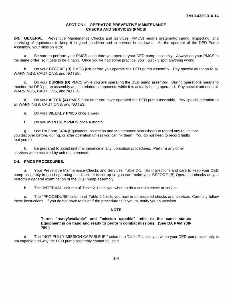
2-3. GENERAL. Preventive Maintenance Checks and Services (PMCS) means systematic caring, inspecting, andservicing of equipment to keep it in good condition and to prevent breakdowns. As the operator of the DED PumpAssembly, your mission is to:
a. Be sure to perform your PMCS each time you operate your DED pump assembly. Always do your PMCS inthe same order, so it gets to be a habit. Once you've had some practice, you’ll quickly spot anything wrong.
b. Do your BEFORE (B) PMCS just before you operate the DED pump assembly. Pay special attention to allWARNINGS, CAUTIONS, and NOTES.
c. Do your DURING (D) PMCS while you are operating the DED pump assembly. During operations means tomonitor the DED pump assembly and its related components while it is actually being operated. Pay special attention allWARNINGS, CAUTIONS, and NOTES.
d. Do your AFTER (A) PMCS right after you have operated the DED pump assembly. Pay special attention toall WARNINGS, CAUTIONS, and NOTES.
e. Do your WEEKLY PMCS once a week.
f. Do you MONTHLY PMCS once a month.
g. Use DA Form 2404 (Equipment Inspection and Maintenance Worksheet) to record any faults thatyou discover before, during, or after operation unless you can fix them. You do not need to record faultsthat you fix.
h. Be prepared to assist unit maintenance in any lubrication procedures. Perform any otherservices when required by unit maintenance.
2-4. PMCS PROCEDURES.
a. Your Preventive Maintenance Checks and Services, Table 2-1, lists inspections and care to keep your DEDpump assembly in good operating condition. It is set up so you can make your BEFORE (B) Operation checks as youperform a general examination of the DED pump assembly.
b. The "INTERVAL" column of Table 2-1 tells you when to do a certain check or service.
c. The "PROCEDURE" column of Table 2-1 tells you how to do required checks and services. Carefully followthese instructions. If you do not have tools or if the procedure tells you to, notify your supervisor.
NOTE
Terms "ready/available" and "mission capable" refer to the same status:Equipment is on hand and ready to perform combat missions. (See DA PAM 738-750.)
d. The "NOT FULLY MISSION CAPABLE IF:" column in Table 2-1 tells you when your DED pump assembly isnot capable and why the DED pump assembly cannot be used.
2-4

TM10-4320-316-14
e. If the DED pump assembly does not perform as required, refer to Section III, Operator Troubleshooting.
f. If anything looks wrong and you can't fix it, write it on your DA Form 2404 IMMEDIATELY and report it toyour supervisor.
g. When you do your PMCS, you will always need a rag or two. The following items are common to all of theDED pump assembly components:
(1) Keep It Clean. Dirt, grease, oil, and debris only get in the way and may cover up a serious problem.Clean as you work and as needed. Use dry cleaning solvent (Appendix E, Item 3) on all metal surfaces. Use soap(Appendix E, Item 10) when you clean rubber or plastic material.
(2) Rust and Corrosion. Check the components of the DED pump assembly for rust and corrosion. Ifany bare metal or corrosion exists, clean and apply a thin coat of oil. Report it to your supervisor.
(3) Bolts, Nuts, and Screws. Check them for obvious looseness, missing, bent, or broken condition.You can't try them all with a tool, but look for chipped paint, bare metal, or rust around bolt heads. If you find a bolt, nut,or screw you think is loose, tighten it or report it to your supervisor.
(4) Welds. Look for loose or chipped paint, rust, or gaps where metal parts are welded together. If youfind a bad weld, report it to your supervisor.
(5) Hoses. Look for wear, damage, or leaks and make sure clamps and fittings are tight. Wet spots showobvious leaks, but a stain around a fitting or connector can also mean a leak. If a leak comes from a loose fitting orconnector, tighten it. If something is broken or worn out, report it to your supervisor.
h. When you check for "proper operating condition", you look at the component to see if its serviceable.
2-5. SPECIAL INSTRUCTIONS. If the equipment must be kept in continuous operation, check and service only thoseitems that can be checked and serviced without disturbing operation. Make the complete checks and services when theequipment can be shut down.
2-6. LEAKAGE DEFINITIONS FOR OPERATOR PMCS. It is necessary for you to know how fluid leakage affects thestatus of the DED pump assembly. Following are types and classes of leakage an operator needs to know to be able todetermine the status of the DED pump assembly. Learn these leakage definitions and remember -- when in doubt,notify your supervisor.
CAUTION
• Equipment operation is allowable with minor leakages (Class I or II). Of course, consideration must be given to fluidcapacity in the item/system being checked/inspected. When in doubt, notify your supervisor.
• When operating with Class I or II leaks, continue to check fluid levels as required by your PMCS.
• Class III leaks should be reported immediately to you supervisor.
2-5

TM10-4320-316-14
2-6. LEAKAGE DEFINITIONS FOR OPERATOR PMCS. - Continued.
a. CLASS I. Seepage of fluid (as indicated by wetness or discolorization) not great enough to form drops.
b. CLASS II. Leakage of fluid great enough to form drops, but not enough to cause drops to drip from itembeing checked/inspected.
c. CLASS III. Leakage of fluid great enough to form drops that fall from item being checked/inspected.
Table 2-1. Operator Preventive Maintenance Checks and ServicesFor DED Pump Assembly. (Refer to Figure 2-2.)
LocationItem Interval Item To Procedure Not Fully MissionNo. Check/Service. Capable If:
1 Before ENCLOSUREASSEMBLY
a. Inspect enclosure assembly fordamage and readability. Check forloose or missing mounting hardware
Mounting hardware isloose or missing.
b. Inspect roll-over frame forbends or cracks. Check for loose ormissing mounting hardware.
.c. Inspect access cover fordamage. Check for loose ormissing mounting hardware.
Access cover isdamaged. Mountinghardware is loose ormissing.
d. Inspect all engine labelsreadability. Check all visible enginegaskets for leaks.
2 Before COMPRESSIONRELEASEHANDLE
Inspect handle for damage. Pushcompression release handle in andthen pull it out. Insure the handleoperates smoothly and does notbind.
Handle is damaged orbinds.
3 Before THROTTLECONTROLHANDLE
Inspect handle for damage and forsmoothness of operation.
Handle is damaged ordoes not operatesmoothly.
4 Before AIR INTAKEHOSE
Inspect that air intake hose isconnected and for damage.
Air intake hose isdisconnected ordamaged
.
2-6
TM10-4320-316-14
Table 2-1. Operator Preventive Maintenance Checks and Servicesfor DED Pump Assembly.
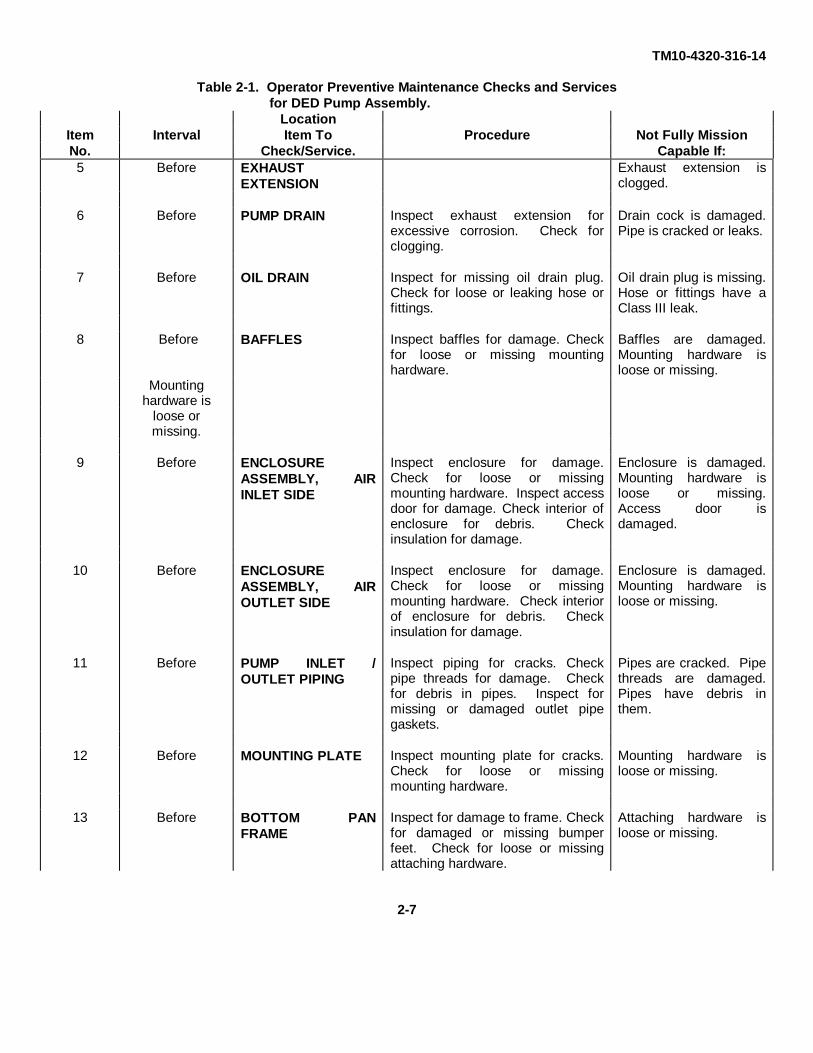
LocationItem Interval Item To Procedure Not Fully MissionNo. Check/Service. Capable If:5 Before EXHAUST
EXTENSIONExhaust extension isclogged.
6 Before PUMP DRAIN Inspect exhaust extension forexcessive corrosion. Check forclogging.
Drain cock is damaged.Pipe is cracked or leaks.
7 Before OIL DRAIN Inspect for missing oil drain plug.Check for loose or leaking hose orfittings.
Oil drain plug is missing.Hose or fittings have aClass III leak.
8 Before BAFFLES Inspect baffles for damage. Checkfor loose or missing mountinghardware.
Baffles are damaged.Mounting hardware isloose or missing.
Mountinghardware is
loose ormissing.
9 Before ENCLOSUREASSEMBLY, AIRINLET SIDE
Inspect enclosure for damage.Check for loose or missingmounting hardware. Inspect accessdoor for damage. Check interior ofenclosure for debris. Checkinsulation for damage.
Enclosure is damaged.Mounting hardware isloose or missing.Access door isdamaged.
10 Before ENCLOSUREASSEMBLY, AIROUTLET SIDE
Inspect enclosure for damage.Check for loose or missingmounting hardware. Check interiorof enclosure for debris. Checkinsulation for damage.
Enclosure is damaged.Mounting hardware isloose or missing.
11 Before PUMP INLET /OUTLET PIPING
Inspect piping for cracks. Checkpipe threads for damage. Checkfor debris in pipes. Inspect formissing or damaged outlet pipegaskets.
Pipes are cracked. Pipethreads are damaged.Pipes have debris inthem.
12 Before MOUNTING PLATE Inspect mounting plate for cracks.Check for loose or missingmounting hardware.
Mounting hardware isloose or missing.
13 Before BOTTOM PANFRAME
Inspect for damage to frame. Checkfor damaged or missing bumperfeet. Check for loose or missingattaching hardware.
Attaching hardware isloose or missing.
2-7

TM10-4320-316-14
Figure 2-2. Operator PMCS Routing Diagram.
2-8

TM10-4320-316-14
Table 2-1. Operator Preventive Maintenance Checks and Servicesfor DED Pump Assembly.
LocationItem Interval Item To Procedure Not Fully MissionNo. Check/Service. Capable If:
14 Before FUEL TANKASSEMBLY
Inspect fuel tank for leaks. Checkfor missing cap. Check for loose ormissing mounting hardware. Checkfuel level (See para. 2-7).
Fuel tank leaks. Cap ismissing. Mountinghardware is loose ormissing.
15 Before FUEL FILTER,INLET
Inspect for damaged or missinginlet fuel filter. Check filter fordebris and clogging.
Inlet fuel filter is missing.Filter is clogged withdebris.
16 Before FUEL COCK Inspect for damaged or leaking fuelcock.
Fuel cock is damaged orleaking.
17 Before FUEL FILTER,OUTLET
Remove fuel tank cap and checkbottom of tank for missing fueloutlet filter.
Fuel outlet filter ismissing.
18 Before PIPE FUELGAUGE
Inspect pipe fuel gauge for leaks.Check for loose or missing clamps.
Pipe fuel gauge leaks.Clamps are loose ormissing.
19 Before FUEL LINES Inspect all fuel lines for damage orleaks. Check for loose or missingclamps.
Fuel lines leak. Clampsare loose or missing.
20 Before AIR CLEANER Inspect air cleaner housing fordamage. Check for loose ormissing mounting hardware.
Air cleaner housing isdamaged. Mountinghardware is loose ormissing.
21 Before FILTERELEMENT
Remove cover from air cleanerhousing and inspect filter forclogging. Check gasket under aircleaner cover for damage.
Filter element is missing.Filter element is verydirty or clogged.
22 Before RECOILSTARTER
Pull starter rope and check thatrecoil starter engages and rotatesengine. Check that recoil starterretracts starter rope when starterrope handle is released.
Starter rope does notengage engine. Starterrope does not retractwhen released.
2-9
TM10-4320-316-14
Table 2-1. Operator Preventive Maintenance Checks and Servicesfor DED Pump Assembly - Continued.
LocationItem Interval Item To Procedure Not Fully MissionNo. Check/Service. Capable If:
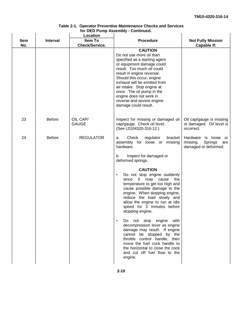
CAUTIONDo not use more oil thanspecified as a starting agentor equipment damage couldresult. Too much oil couldresult in engine reversal.Should this occur, engineexhaust will be emitted fromair intake. Stop engine atonce. The oil pump in theengine does not work inreverse and severe enginedamage could result.
23 Before OIL CAP/GAUGE
Inspect for missing or damaged oilcap/gauge. Check oil level.(See L0104320-316-12.)
Oil cap/gauge is missingor damaged. Oil level isincorrect.
24 Before REGULATOR a. Check regulator bracketassembly for loose or missinghardware.
b. Inspect for damaged ordeformed springs.
Hardware is loose ormissing. Springs aredamaged or deformed.
CAUTION• Do not stop engine suddenly
since it may cause thetemperature to get too high andcause possible damage to theengine. When stopping engine,reduce the load slowly andallow the engine to run at idlespeed for 3 minutes beforestopping engine.
• Do not stop engine withdecompression lever as enginedamage may result. If enginecannot be stopped by thethrottle control handle, thenmove the fuel cock handle tothe horizontal to close the cockand cut off fuel flow to theengine.
2-10

TM10-4320-316-14
Table 2-1. Operator Preventive Maintenance Checks and Servicesfor DED Pump Assembly - Continued.
LocationItem Interval Item To Procedure Not Fully MissionNo. Check/Service. Capable If:25 During COMPRESSION
RELEASEHANDLE
Check that handle is in up positionwhile engine is operating.
26 During PUMP DRAIN Check drain cock for leaks. Inspectpipe for leaks.
Pipe or drain cock has aClass III leak.
27 During PUMP INLET /OUTLET PIPING
Inspect outlet piping for leaks. Pipes leak during pumpingoperation.
28 During EXHAUSTSILENCER
Check for excessive noise orobvious exhaust gas leaks.
2-11
TM10-4320-316-14
SECTION III. OPERATION UNDER USUAL CONDITIONS
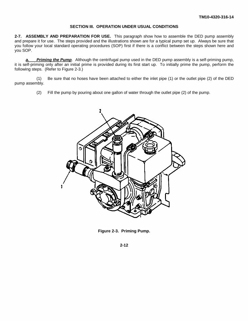
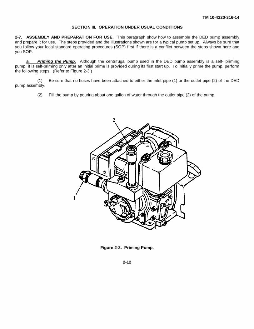
2-7. ASSEMBLY AND PREPARATION FOR USE. This paragraph show how to assemble the DED pump assemblyand prepare it for use. The steps provided and the illustrations shown are for a typical pump set up. Always be sure thatyou follow your local standard operating procedures (SOP) first if there is a conflict between the steps shown here andyou SOP.
a. Priming the Pump. Although the centrifugal pump used in the DED pump assembly is a self-priming pump,it is self-priming only after an initial prime is provided during its first start up. To initially prime the pump, perform thefollowing steps. (Refer to Figure 2-3.)
(1) Be sure that no hoses have been attached to either the inlet pipe (1) or the outlet pipe (2) of the DEDpump assembly.
(2) Fill the pump by pouring about one gallon of water through the outlet pipe (2) of the pump.
Figure 2-3. Priming Pump.
2-12

TM10-4320-316-14
Table 2-1. Operator Preventive Maintenance Checks and Servicesfor DED Pump Assembly - Continued.
LocationItem Interval Item To Procedure Not Fully MissionNo. Check/Service. Capable If:
25 During COMPRESSIONRELEASEHANDLE
Check that handle is in up positionwhile engine is operating.
26 During PUMP DRAIN Check drain cock for leaks. Inspectpipe for leaks.
Pipe or drain cock has aClass III leak.
27 During PUMP INLET /OUTLET PIPING
Inspect outlet piping for leaks. Pipes leak during pumpingoperation.
28 During EXHAUSTSILENCER
Check for excessive noise orobvious exhaust gas leaks.
2-11
TM 10-4320-316-14
SECTION III. OPERATION UNDER USUAL CONDITIONS
2-7. ASSEMBLY AND PREPARATION FOR USE. This paragraph show how to assemble the DED pump assemblyand prepare it for use. The steps provided and the illustrations shown are for a typical pump set up. Always be sure thatyou follow your local standard operating procedures (SOP) first if there is a conflict between the steps shown here andyou SOP.
a. Priming the Pump. Although the centrifugal pump used in the DED pump assembly is a self- primingpump, it is self-priming only after an initial prime is provided during its first start up. To initially prime the pump, performthe following steps. (Refer to Figure 2-3.)
(1) Be sure that no hoses have been attached to either the inlet pipe (1) or the outlet pipe (2) of the DEDpump assembly.
(2) Fill the pump by pouring about one gallon of water through the outlet pipe (2) of the pump.
Figure 2-3. Priming Pump.
2-12
TM 10-4320-316-14
b. Filling the Fuel Tank. Before starting the DED pump assembly, the fuel tank must be filled with fuel. To fillthe fuel tank, perform the following procedures. (Refer to Figure 2-4.)
(1) Disengage the latch (1) on the access panel (2) of the enclosure assembly (3) and open access cover.
(2) Check the pipe fuel gauge (4) on the side of the fuel tank (5) to insure that fuel tank is filled with fuel.If fuel tank is not full, perform steps (3) through (6) to fill the tank.
WARNING
Improper care in handling fuel can cause fire and explosion which can cause severeinjury or death to operating personnel. To avoid fire or explosion during enginerefueling:
• DO NOT allow any flame producing material within 50 feet (15.25 m) of fuel duringequipment filling.
• DO NOT smoke while refueling.• DO NOT let fuel drip onto any hot surface.• DO NOT overfill fuel tank.• DO NOT refuel unit while engine is running.
(3) Remove fuel tank cap (6).
(4) Check the inlet fuel filter (7) inside the top of the fuel tank (5) and carefully remove any debris thatmay have collected inside the filter.
(5) Carefully pour fuel from the fuel container into the fuel tank (5) while checking the pipe fuel gauge (4)on the side of the fuel tank. When the pipe fuel gauge indicates that the tank is full, stop filling the fuel tank.
(6) Replace fuel tank cap (6) onto fuel tank (5).
2-13

TM 10-4320-316-14
Figure 2-4. Refueling DED Pump Assembly.
2-14

TM 10-4320-316-14
c. Assembly for Use. The DED pump assembly itself does not require any assembly. However, it must beproperly connected to a water system before operation. To connect the DED pump assembly into your water system,perform the following steps. (Refer to Figure 2-3.)
(1) Connect discharge hose to outlet pipe (2) of the DED pump assembly.
(2) Connect one end suction hose to the inlet pipe (1) of the DED pump assembly and connect other endof suction hose to water source. Highest point in the suction hose should be at the DED pump assembly.
2-8. INITIAL ADJUSTMENTS, DAILY CHECKS, AND SELF TESTS.
a. Inspect all DED pump assembly for completeness, damage, and for proper operation as applicable.Report any deficiencies to unit maintenance.
b. Perform the "Before" preventative maintenance checks and services listed in Table 2-1
2-9. OPERATING PROCEDURES.
a. Starting. After insuring that the DED pump assembly has been properly connected as indicated in para.2-7, the DED pump assembly may be started by performing the following steps. (Refer to Figure 2-5.)
CAUTIONStarting the DED pump assembly before the pump has been initially primed cancause serious damage to the pump. Be sure that the pump has been initiallyprimed as shown in para. 2-7.
(1) Perform all "Before" Operator PMCS listed in Table 2-1.
(2) Disengage the latch (1) on the access cover (2) of the enclosure assembly (3) and open access cover.
(3) Set fuel cock (4) to open position by turning handle to the downward position.
(4) Rotate throttle control handle (5) 1/4 turn counterclockwise, pull handle all the way out, and twisthandle 1/4 clockwise to lock throttle in fully open position.
(5) Slowly pull out starting handle (6) until you feel resistance, and then return it to the initial position.
(6) Push the decompression lever down (7) and release. It will return automatically to the normal positionwhen the recoil starter is pulled.
CAUTION
Do not allow the handle grip to snap back. Return It gently to prevent damage tothe starter.
(7) Hold recoil starting handle (6) firmly and pull out the handle briskly. Engine will start and go tomaximum operating speed
2-15

TM 10-4320-316-14
Figure 2-5. Starting and Operating the DED Pump Assembly.
2-16
TM 10-4320-316-14
NOTE
If engine does not start on first pull, repeat steps (5), (6), and (7).
(8) After 1 to 3 minutes, the centrifugal pump will start pumping water.
(9) Close access panel (2) and engage latch (1).
b. Adjusting Speed. After engine has been started, the engine speed must be adjusted to set the DED pumpassembly to pump the required rate of water. To adjust the engine speed, perform the following steps. (Refer to Figure2-5.)
(1) Rotate throttle control handle (5) 1/4 turn counterclockwise and either pull out the throttle control toincrease speed or push in throttle control handle to decrease speed until desired pumping rate is achieved.
(2) Rotate throttle control handle (5) 1/4 turn clockwise to lock handle when the desired speed andpumping rate are achieved.
c. Stopping. When the pumping operation is complete, the DED pump assembly must be shutdown bystopping the engine. To shutdown the DED pump assembly, perform the following steps. (Refer to Figure 2-5.)
CAUTION
• Do not stop engine suddenly since it may cause the temperature to get toohigh and cause possible damage to the engine. When stopping the engine,reduce the load slowly and allow the engine to run at idle speed for 3 minutesbefore stopping engine.
• Do not stop engine with the decompression lever as engine damage mayresult. If the engine cannot be stopped by the throttle control, then move thefuel cock handle to the horizontal to close the cock and cut off fuel flow to theengine.
(1) Rotate throttle control handle (5) 1/4 turn counterclockwise and slowly move throttle down until engineis running at idle speed. Lock throttle control into this idle position by rotating throttle control handle 1/4 turn clockwise.
(2) Allow engine to run at idle speed for 3 minutes.
(3) Close any discharge water valve in the water system and then close any suction valves that areinstalled in the hoses. This will retain liquid in pump unit and reduce or eliminate the need to prime the pump for the nextpumping application.
(4) Rotate throttle control handle (5) 1/4 turn counterclockwise and push throttle control handle all the waydown to stop the engine.
2-17
TM 10-4320-316-14
2-10. PREPARATION FOR MOVEMENT. When the DED pump assembly is to be moved, the services of unitmaintenance shall be employed for the necessary preparations. For general preparation of the DED pump assembly formovement, perform the following steps (Refer to Figure 2-3).
a. Disconnect suction hose from DED pump assembly inlet pipe (1).
b. Disconnect discharge hose from DED pump assembly outlet pipe (2).
c. Open pump drain cock on the bottom pan frame and allow all water to drain from pump unit.
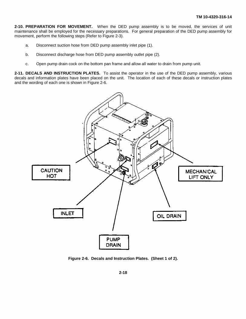
2-11. DECALS AND INSTRUCTION PLATES. To assist the operator in the use of the DED pump assembly, variousdecals and information plates have been placed on the unit. The location of each of these decals or instruction platesand the wording of each one is shown in Figure 2-6.
Figure 2-6. Decals and Instruction Plates. (Sheet 1 of 2).
2-18

TM 10-4320-316-14
Figure 2-6. Decals and Instruction Plate. (Sheet 2 of 2).
2-19

TM 10-4320-316-14
SECTION IV. OPERATION UNDER UNUSUAL CONDITIONS
2-12. OPERATION UNDER UNUSUAL WEATHER. The DED pump assembly is designed to operate normally within awide range of climatic conditions. However, some extreme conditions require special operating and servicing proceduresto prevent undue loading and excessive wear on the equipment. These unusual conditions and the special steps to beperformed are listed in the following paragraphs.
a. Operation in Extreme Cold. (Refer to Figure 2-7.)
CAUTIONFreezing water can badly damage the DED pump assembly components. Whenpumping operations are completed at temperatures near 32°F (0°C), disconnecteach end of all hose assemblies to prevent freezing water from damagingequipment. This equipment is not designed for operation below 32°F (0°C).
(1) Be sure to use proper engine oil for cold weather. Refer to Lubrication Order LO10-4320-316-12 forthe correct type of oil to use in the temperatures you will be experiencing.
(2) Keep fuel tank full to prevent condensation. Condensation can freeze and clog the lines, filters, andinjectors. Water in the fuel can also make the engine hard to start and may make the engine run very roughly.
WARNING
Use of gasoline, paint thinner, or any other volatile liquid either as a fuel or as astarting aid can result in serious injury to operating personnel. Addition of highlyvolatile liquids put directly into engine could cause an explosion or fire.
CAUTION
Do not use more oil than specified as a starting agent or equipment damage couldresult. Too much oil could result in engine reversal. Should this occur, engineexhaust will be emitted from the air intake. Stop engine at once. The oil pump inthe engine does not work in reverse and severe engine damage could result.
CAUTION
If plug is not in place contaminants may enter engine and cause accelerated wearof internal parts. Keep rubber plug in rocker arm cover except when adding oil forcold weather starting.
(3) Cold weather starting can be improved by the addition of engine oil in rocker arm cover.Remove rubber plug (1) of rocker arm cover and add five or six drops of engine oil before starting.
(4) Replace rubber plug (1) immediately after oil is added.
(5) Start the engine immediately as described in paragraph 2-9.
2-20

TM 10-4320-316-14
Figure 2-7. Cold Weather Starting Aid.
b. Operation in Extreme Heat.
(1) Protect pump assembly from direct heat of the sun.
(2) Make sure oil is maintained on the top oil level mark Refer to Lubrication Order L010-4320-316-12.
(3) If overheating occurs in extreme conditions, shut down engine immediately. Be sure unit is operated in awell ventilated area capable of allowing exhaust air to dissipate and to allow cool fresh air to enter engine intake Ifpossible protect pump assembly from direct heat or the sun
c. Operation in Sandy or Dusty Areas. Dusty and sandy conditions can seriously affect the operation of the DEDpump assembly. When operating the DED pump assembly in these dusty and sandy conditions, perform the followingsteps.
(1) Accumulation of dust or sand in the filters of the diesel engine will cause the pump to overheat anddamage the equipment. Have engine air filter replaced by unit maintenance and clean all other areas of dust and sandaccumulation frequently. In extreme conditions, daily replacement of filter may be necessary.
(2) Water which has been contaminated by dust and sand can severely affect the usability of the water beingpumped by the DED pump assembly Special care must be taken that the water being pumped does not have dust orsand in it when using the DED pump assembly in dusty and sandy conditions. Be sure that all hose and pipingconnections are tight. Be sure that the insides of all DED pump assembly components are clean before pipingconnections are made during DED pump assembly set up and assembly.
2-21
TM 10-4320-316-14
2-12. OPERATION UNDER UNUSUAL WEATHER. - Continued.
c. Operation in Sandy or Dusty Areas. - Continued.
(3) Check engine oil more often to make sure oil level is maintained at the top mark. Refer to LubricationOrder LO10-4310-316-12.
(4) During the handling of fuel, while performing any PMCS procedure, or while refueling, be sure that sand ordust is not allowed to enter fuel or lubrication system.
(5) If DED pump assembly is not in use and suction and/or discharge hoses are not installed, be sure that inletand outlet pipe openings are covered.
d. Operation in Salt Water Areas. The nature of salt presents serious corrosion problems. Frequent cleaning isnecessary during which all exposed surfaces should be thoroughly sprayed, rinsed, or sponged with fresh water toremove salt. Keep inlet and outlet pipes on the DED pump assembly free from dried salt to insure that water being pumpfor potable water use is not contaminated.
2-13. EMERGENCY PROCEDURES. Loss of suction requires a shutdown of the diesel-driven centrifugal pump as soonas possible.
CAUTION
Do not stop engine with the decompression lever as engine damage may result. If theengine cannot be stopped by the throttle control handle, then move the fuel cock to theclosed position to stop the flow of fuel to the engine.
Rotate throttle control handle 1/4 turn counterclockwise and push handle all the way down to stop engine.
2-14. NUCLEAR, BIOLOGICAL, AND CHEMICAL (NBC) DECONTAMINATION PROCEDURES. In the event that thepumping assembly has been subjected to NBC contamination, follow the NBC procedures in FM 3-3, FM 3-4, and FM 3-5.
2-22

TM 10-4320-316-14
CHAPTER 3OPERATOR MAINTENANCE INSTRUCTIONS
SECTION I. LUBRICATION INSTRUCTIONS
3-1. GENERAL. Refer to Lubrication Order LO10-4320-316-12 for the for proper lubrication procedures.
SECTION II. OPERATOR TROUBLESHOOTING PROCEDURES
3-2. INTRODUCTION. This section contains troubleshooting information for locating and correcting most of theoperating troubles which may develop in the DED pump assembly. Each malfunction for an individual component, unit,or system is followed by a list of tests or inspections which will help you to determine corrective actions to take Youshould perform the tests/inspections and corrective actions in the order listed.
This manual cannot list all malfunctions that may occur, nor all tests or inspections and corrective actions. If amalfunction is not listed, or is not corrected by listed corrective actions, notify your supervisor.
Table 3-1 lists the common malfunctions which you may find during the operation or maintenance of the DED pumpassembly or its components. You should perform the tests/inspections and corrective actions in the order listed.
3-3. MALFUNCTION INDEX.
MALFUNCTION PAGE NO.
STARTING HANDLE FAILS TO PULL ........................................................................... 3-2STARTING HANDLE PULLS, BUT ENGINE FAILS TO START ..................................... 3-2ERRATIC RUNNING OR FREQUENT STALLING.......................................................... 3-2LACK OF POWER ......................................................................................................... 3-2ENGINE STOPS RUNNING........................................................................................... 3-3PUMP FAILS TO PUMP WATER................................................................................... 3-3LOW DISCHARGE FLOW RATE................................................................................... 3-3
3-4. OPERATOR TROUBLESHOOTING TABLE. Refer to Table 3-1 for the operator troubleshooting proceduresauthorized for the DED pump assembly.
3-1

TM 10-4320-316-14
Table 3-1. Operator Troubleshooting.
MALFUNCTIONTEST OR INSPECTION
CORRECTIVE ACTION
1. STARTING HANDLE FAILS TO PULL.
Check decompression lever.
Push decompression lever down to release engine compression. (Refer to para2-9.)
If starting handle still fails to pull, notify Unit Maintenance.
2. STARTING HANDLE PULLS, BUT ENGINE FAILS TO START.
Step 1. Check fuel cock.
Open fuel cock, if closed (refer to para 2-9).
If fuel cock is open proceed to step 2.
Step 2. Check position of throttle control handle.
Move to START position (refer to para 2-9).
If throttle control handle is properly positioned, proceed to step 3.
Step 3. Check the starting procedure under prevailing conditions. (Refer to Chapter 2, Section III or IV.)
If the starting procedures have been performed correctly ND engine still fails tostart, notify Unit Maintenance.
3. ERRATIC RUNNING OR FREQUENT STALLING.
Check for partially closed fuel cock.
Fully open the fuel cock, if closed (refer to para 2-9).
If unit still runs improperly, notify Unit Maintenance.4. LACK OF POWER.
Step 1. Check position of throttle control handle.
Move to START position to increase engine speed (refer to para 2-9).
If engine still lacks power, proceed to step 2.
3-2

TM 10-4320-316-14
Table 3-1. Operator Troubleshooting.
MALFUNCTIONTEST OR INSPECTION
CORRECTIVE ACTION
Step 2. Check for clogged suction hose in system.
Check all suction hoses attached to inlet pump piping for clogged or collapsedhoses. Clean out clogged hoses and reposition or replace collapsed suction hoses.(Refer to system technical manual).
If suction hoses are not clogged or collapsed, contact Unit Maintenance.
5. ENGINE STOPS RUNNING.
Check for low fuel supply.
Fill fuel tank, if necessary.
If fuel tank has fuel, notify Unit Maintenance.
6. PUMP FAILS TO PUMP WATER.
Step 1. Check pump priming procedure. (Refer to para. 2-9).
If pump is properly primed, proceed to Step 2.
Step 2. Check for clogged suction hose.
If clogged, clean suction hose. Refer to system technical manual.
If suction hose is not clogged, proceed to Step 3.
Step 3. Check for leaks in the pump suction line.
Repair leaks in pump suction line. Refer to system technical manual.
If suction line is not clogged, notify Unit Maintenance.
7. LOW DISCHARGE FLOW RATE.
Step 1. Check for low engine speed.
Move throttle control handle to START position to increase engine speed (referto para 2-9).
If engine speed is correct, proceed to step 2.
3-3

TM 10-4320-316-14
Table 3-1. Operator Troubleshooting. - Continued.
MALFUNCTIONTEST OR INSPECTION
CORRECTIVE ACTION
Step 2. Check for lack of engine power.
Refer to MALFUNCTION 4.
If engine does not lack power, proceed to step 3.
Step 3. Check for clogged suction hose.
If clogged, clean suction hose. Refer to system technical manual.
If suction hose is not clogged, proceed to Step 4.
Step 4. Check for leaks in the pump suction line.
Repair leaks in suction port connections. Refer to system technical manual.
If suction line is not leaking, notify Unit Maintenance.
3-4

TM 10-4320-316-14
SECTION III. OPERATOR MAINTENANCE PROCEDURES
3-5. GENERAL. This section contains the maintenance procedures which the Maintenance Allocation Chart authorizesthe operator to perform. If the DED pump assembly still does not operate properly after performing these maintenanceprocedures, contact unit maintenance for assistance.
3-6. SERVICING FUEL INLET FILTER. To service the fuel inlet filter, perform the following steps. (Refer to Figure3-1.)
a. Removal
(1) Remove fuel tank cap (1) from fuel tank (2)
(2) Remove fuel inlet filter (3) from fuel tank (2).
b. Servicing.
(1) Remove any debris that has collected inside the fuel inlet filter (3).
(2) If fuel inlet filter cannot be cleaned, contact unit maintenance for a replacement filter.
c. Installation.
(1) Install fuel inlet filter (3) into fuel tank (2)
(2) Install fuel tank cap (1) onto fuel tank (2).
Figure 3-1. Servicing Fuel Inlet Filter.
3-5

TM 10-4320-316-14
3-7. SERVICING ENGINE AIR CLEANER FILTER ELEMENT. To service the engine air cleaner filter element, performthe following steps. (Refer to Figure 3-2.)
a. Removal
(1) Remove wing nut (1) and washer (2).
(2) Remove air cleaner cover (3) from air cleaner assembly (4).
(3) Remove air cleaner element (5) from air cleaner assembly (4).
b. Servicing.
(1) Remove any dirt are debris from inside air cleaner housing.
(2) If filter element is dirty, contact unit maintenance for a replacement element.
c. Installation.
(1) Install air cleaner element (5) into air cleaner assembly (4).
(2) Install air cleaner cover (3) onto air cleaner assembly (4) and install washer (2) and wing nut (1).
Figure 3-2. Servicing Air Cleaner Filter Element.
3-6

TM 10-4320-316-14
CHAPTER 4
UNIT MAINTENANCE INSTRUCTIONS
SECTION I. REPAIR PARTS, SPECIAL TOOLS, TEST, MEASUREMENT, ANDDIAGNOSTIC EQUIPMENT (TMDE), AND SUPPORT EQUIPMENT
4-1. COMMON TOOLS AND EQUIPMENT. For authorized common tools and equipment, refer to the Modified Table ofOrganization and Equipment (MTOE) applicable to your unit.
4-2. SPECIAL TOOLS, TMDE, AND SUPPORT EQUIPMENT. No special tools are required for maintenance of theequipment. Test, Measurement, and Diagnostic Equipment (TMDE) and Support Equipment include standard equipmentfound in any maintenance shop.
4-3. REPAIR PARTS. Repair parts are listed and illustrated in the Repair Parts and Special Tools List (RPSTL), TM 10-4320-316-24P, covering unit, direct support, and general support maintenance for this equipment.
SECTION II. SERVICE UPON RECEIPT
4-4. SITE AND SHELTER REQUIREMENTS. Before beginning installation of the DED pump, be sure that you haveselected the proper site and shelter for the unit as described in the following paragraphs.
WARNING
CARBON MONOXIDE (EXHAUST GAS) CAN KILL YOUCarbon monoxide is without color or smell, but can kill you. Breathing air with carbon monoxide producessymptoms of headache, dizziness, loss of muscular control, a sleepy feeling, and coma. Heavy exposurecan cause brain damage or death. Carbon monoxide gas occurs in the exhaust fumes of internalcombustion engines, and can become dangerously concentrated under conditions of no air movement. Toensure your safety and that of other maintenance personnel, always observe the following precautions:
• DO NOT operate engine in a closed place unless the place has a lot of moving air Engine should bekept at least five feet away from buildings and other equipment during operation.
• DO NOT idle engine for long periods without proper ventilation. • BE ALERT at all times for exhaust odors and exposure symptoms. If either is present, IMMEDIATELY
VENTILATE personnel compartments; remove affected crew to fresh air; keep warm; if necessary,give artificial respiration. FOR ARTIFICIAL RESPIRATION REFER TO FM 21-11.
• BE AWARE; the field protective mask for chemical-biological-radiological (CBR) protection will not
protect you against carbon monoxide poisoning.
THE BEST DEFENSE AGAINST CARBON MONOXIDE POISONING IS GOOD VENTILATION.
4-1
TM 10-4320-316-14
4-4. SITE AND SHELTER REQUIREMENTS. Continued.
a. Siting. Select an installation site for the DED pump assembly that is relatively level. Be very sure that the siteyou have selected will provide adequate air circulation around the unit to prevent dangerous accumulation of poisonousexhaust gases from the engine.
b. Shelter Requirements. Operation of the DED pump within a shelter is not recommended since the collection ofexhaust gases present extremely dangerous hazards to operating personnel.
4-5. SERVICE UPON RECEIPT. The following paragraphs contain the procedures for unloading, unpacking, andgeneral checking of the unpacked DED pump.
a. Unloading. The DED pump is packaged in a container designed for shipment and handling with the unit in anupright position. The base of the container is constructed as a shipping pallet with provisions for the insertion of thetongs of a fork-lift. The unit may be lifted by fork-lift, crane, or sling. To unload the DED pump, perform the followingsteps.
(1) Remove all blocking and tie downs that may have been used to secure the container to the carrier.
WARNINGDo not allow the unit to swing while suspended from a lifting device. Failure to observethis warning may result in injury to personnel and damage to the equipment.
CAUTIONUse care in handling to avoid damage to the DED pump. If an overhead lifting devicemust be used, use an appropriate sling so that the weight of the unit is supported by thebase of the shipping container.
(2) Use a forklift truck or other suitable material handling equipment to remove the unit from the carrier.
b. Unpacking.
CAUTIONTo protect the DED pump and prevent damage, the DED pump should be left packageduntil it is moved to the location where it is to be installed.
NOTEThe shipping container is of such a design that it may be retained for re-use for mobilitypurposes if frequent relocation of the DED pump is anticipated.
(1) Cut the metal bands that hold the top of the shipping container to the base.
(2) Remove the cushioning around the top of the unit's sound enclosure and retain, if re-use is anticipated.
4-2

TM 10-4320-316-14
(3) Remove the preservation barrier by tearing around the bottom of the unit.
(4) Remove the technical publications envelope and accessory sack that are taped to the unit and put them ina safe place.
WARNINGTo avoid serious injury to personnel, always use a suitable lifting device to move or liftpumping assembly.
(5) Remove the DED pump from the shipping container by lifting it up and out of the container. Place the unitinto a position where it can be checked for completeness and possible shipping damage.
(6) Remove the shipping container from the site and retain it if re-use is anticipated. Be sure to remove allremaining barrier material from the underside of the unit.
c. Checking Unpacked Equipment. To check the unpacked DED pump, perform the following steps.
(1) Inspect the equipment for damage incurred during shipment. If the equipment has been damaged, reportdamage on DD Form 6, Packaging Improvement Report.
(2) Check the equipment against the packing slip to see if the shipment is complete. Report all discrepanciesin accordance with the instructions as defined within DA PAM 738-750. See that all components of enditem and basic issue items are with the equipment.
(3) Check to see whether the equipment has been modified.
4-6. INSTALLATION INSTRUCTIONS. Before the DED pump can be properly operated, the unit must be installed intothe system which requires the use of the pump. To install the DED pump into the system, perform the followinginstructions.
a. Tools, Test Equipment, and Materials Needed for Installation. The standard tool kit commonly available tounit level maintenance contains all the tools required to install the DED pump.
b. Assembly of Equipment.
CAUTIONImproper installation of pipe fittings can cause the DED pump to leak badly and couldcause damage to the pump or other system components. Be sure that all threaded malepipe fittings have four clockwise wraps of teflon tape before fittings are installed.
(1) Install feet to bottom pan frame (refer to para. 4-25.)
(2) Install the suction hose to be used in the system onto the suction port of the DED pump. Highest point mthe suction hose should be at the pump.
(3) Install the discharge hose to be used in the system onto the outlet port of the DED pump.
4-3

TM 10-4320-316-14
4-6. INSTALLATION INSTRUCTIONS. Continued.
b. Assembly of Equipment. - Continued.
(4) Make sure all connections are tight.
(5) After the DED pump has been assembled, the following steps must be performed before attempting to startthe engine.
(a) Fill the fuel tank with diesel fuel (Refer to paragraph 2-7).
(b) Make sure the engine is perfectly level. Remove the dipstick cap and fill with oil according to theambient temperature. (Refer to L010-4320-316-12.)
(c) Check the oil level by inserting the dipstick into the oil pan without screwing in the dipstick.
(d) Check that there is no obstruction in front of the air intake opening that might impede the flow ofcooling air.
(e) Check that there is no obstruction that might hinder pull-rope action.
SECTION III. LUBRICATION
4-7. GENERAL. Refer to Lubrication Order LO10-4320-316-12 for the lubrication instructions required for this unit.
4-4

TM 10-4320-316-14
SECTION IV. UNIT PREVENTIVE MAINTENANCE CHECKS AND SERVICES (PMCS)
4-8. INTRODUCTION. Systematic, periodic, Preventive Maintenance Checks and Services (PMCS) are essential toensure that the DED pump is ready for operation at all times. The purpose of a preventive maintenance program is todiscover and correct defects and deficiencies before they can cause serious damage or complete failure of theequipment. Any effective preventive maintenance program must begin with the indoctrination of operators to report allunusual conditions notes during daily checks or actual operation to unit maintenance. All defects and deficienciesdiscovered during maintenance inspections must be recorded, together with corrective action taken, on DA Form 2404(Equipment Inspection and Maintenance Worksheet).
A schedule for unit preventive maintenance inspection and service should be established immediately after installation ofthe DED pump. A quarterly interval, equal to three calendar months or 250 hours of operation (whichever occurs first) isrecommended for usual operating conditions. When operating under unusual conditions, such as a very dusty or sandyenvironment, It may be necessary to reduce the interval to monthly or even less if conditions are extreme.
Table 4-1 lists the unit preventive maintenance checks and services that should be performed at quarterly (or otherwiseestablished) intervals. The PMCS items in the table have been arranged and numbered in a logical sequence to providefor greater personnel efficiency and least amount of required maintenance downtime.
4-9. PMCS TABLE. Refer to Table 4-1. for the unit Preventive Maintenance Checks and Services required for the DEDpump. A description of the columns in the table is included in the following paragraphs.
a. Item Number Column. This column is a list of every check and service task in the PMCS. They are numberedin logical order of performance regardless of the interval. This column is to be used as a source of item numbers for theTM Number Column on DA Form 2404, Equipment Inspection and Maintenance Worksheet, in recording results ofPMCS.
b. Interval Column. This column is subdivided into four categories. W-Weekly, M-Monthly, Q-Quarterly, and S-Semi-annually. A dot in the appropriate column signifies the interval at which a specific item needs to be checked orserviced.
c. Item To Be Inspected Column. This column provides the name of the item to be checked or serviced.
d. Procedures Column. This column describes the procedures to check or service an item. It includes all theinformation required to perform the checks or services. It indicates tolerances where applicable, adjustment limits, andreading levels where required.
4-5

TM 10-4320-316-14
Table 4-1. Unit Preventive Maintenance Checks and Services (PMCS)
LocationItem Interval Item To Check/ Procedure Not Fully MissionNo. Service Capable If
1 Monthly Suction FlangeAssembly
a. Tilt open outlet enclosure (refer to para.4-23)
b Remove hose connection adapter (1),coupling (2), and pipe nipple (3) fromsuction pipe flange assembly (4) on unit(5).
c. Look into port of suction flangeassembly (4) to check that internalgasket is not missing or damaged orthat either of the two weights on thegasket are not missing or damaged.
d. If the gasket has been damaged, notifydirect support maintenance.
e. Install pipe nipple (3), coupling (2) andhose connection adapter (1) into suctionflange assembly (4).
f . Close outlet enclosure (refer topara 4-23).
Gasket or gasket weightsmissing or damaged
4-6
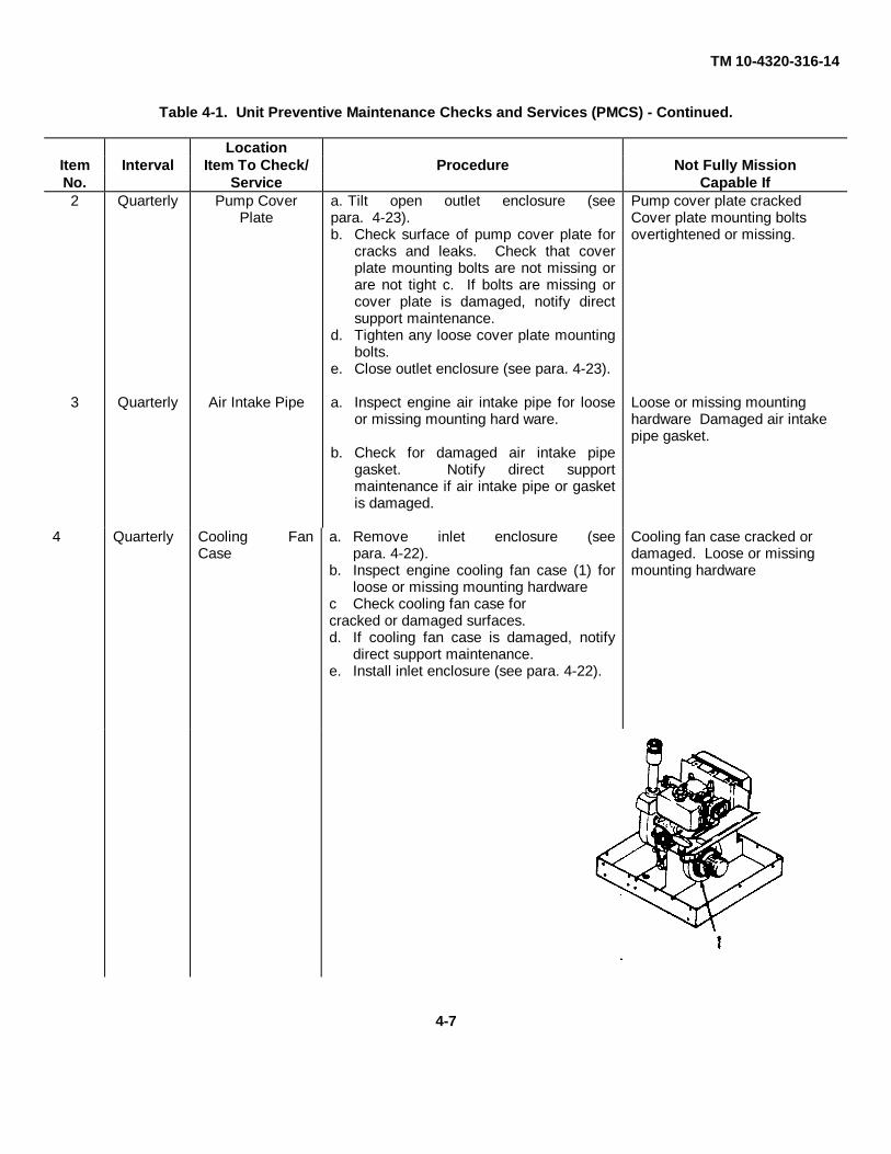
TM 10-4320-316-14
Table 4-1. Unit Preventive Maintenance Checks and Services (PMCS) - Continued.
LocationItem Interval Item To Check/ Procedure Not Fully MissionNo. Service Capable If2 Quarterly Pump Cover
Platea. Tilt open outlet enclosure (seepara. 4-23).b. Check surface of pump cover plate for
cracks and leaks. Check that coverplate mounting bolts are not missing orare not tight c. If bolts are missing orcover plate is damaged, notify directsupport maintenance.
d. Tighten any loose cover plate mountingbolts.
e. Close outlet enclosure (see para. 4-23).
Pump cover plate crackedCover plate mounting boltsovertightened or missing.
3 Quarterly Air Intake Pipe a. Inspect engine air intake pipe for looseor missing mounting hard ware.
b. Check for damaged air intake pipegasket. Notify direct supportmaintenance if air intake pipe or gasketis damaged.
Loose or missing mountinghardware Damaged air intakepipe gasket.
4 Quarterly Cooling FanCase
a. Remove inlet enclosure (seepara. 4-22).
b. Inspect engine cooling fan case (1) forloose or missing mounting hardware
c Check cooling fan case forcracked or damaged surfaces.d. If cooling fan case is damaged, notify
direct support maintenance.e. Install inlet enclosure (see para. 4-22).
Cooling fan case cracked ordamaged. Loose or missingmounting hardware
4-7

TM 10-4320-316-14
Table 4-1. Unit Preventive Maintenance Checks and Services (PMCS)
LocationItem Interval Item To Check/ Procedure Not Fully MissionNo. Service Capable If5 Quarterly Lube Oil Strainer a. Remove inlet enclosure (see para. 4-
22).b. Remove bolt (1), lube oil strainer (3),
and O-ring (2).
c. Clean any dirt and debris that may havecollected in the lube oil strainer (3)
d. Check lube oil strainer (3) for damagedscreen or cracked 0-rng (2) If repairs arerequired, refer to para. 4-35.
e. Install O-ring (2), lube oil strainer (3),and bolt (1).
f . Install inlet enclosure (see para. 4-22).n
Lube oil strainer dirty. Lube oilstainer screen O- ring damagedor cracked.
6 Annually Baffles a. Check baffles for missing, loose ordamaged rubber seals.
b. If baffles are damaged, refer to para 4-21 to repair baffles.
Baffles rubber seals missing ordamaged
7
8
Annually
Annually
Fuel Filter, Outlet
Exhaust Silencer
Replace outlet fuel filter (see para. 4-29).
a. Check exhaust silencer for holes.
b. If exhaust silencer is defective, notifydirect support maintenance
4-8
TM 10-4320-316-14
SECTION V. UNIT TROUBLESHOOTING PROCEDURES.
4-10. GENERAL. This section contains troubleshooting information for locating and correcting most of the operatingtroubles which may develop in the DED pump. Each malfunction for an individual component, unit, or system is followedby a list of tests or inspections which will help you to determine corrective actions to take. You should perform thetests/inspections and corrective actions in the order listed.
In general, engine exhaust is an excellent way to tell what kind of condition your centrifugal pump is in. Exhaust color ofblack, or bluish-white, smoke is normal before the engine warms up fully. As the engine reaches normal operatingtemperature, the exhaust becomes clear or light blue, provided there are no problems. If the exhaust does not clear up,a problem is indicated.
When exhaust color is abnormal, turn off the engine immediately and notify your supervisor. Use Table 4-2 as aguideline to exhaust symptoms.
Table 4-2. Troubleshooting by Exhaust Color.
EXHAUST COLOR: LIKELY INDICATES:
Clear or light bluish condition Normal operating
Continuous black smoke OverloadingSeizure of moving partIncorrect combustion
Continuous bluish-white smoke Lubricating oil is beingconsumed
This manual cannot list all malfunctions that may occur, nor all tests or inspections and corrective actions. If amalfunction is not listed, or is not corrected by listed corrective actions, notify your supervisor.
Table 4-3 lists the common malfunctions which you may find during the operation or maintenance of the DED pump.You should perform the tests/inspections and corrective actions in the order listed.
4-9

TM 10-4320-316-14
WARNINGCARBON MONOXIDE (EXHAUST GAS) CAN KILL YOU
Carbon monoxide is without color or smell, but can kill you. Breathing air with carbon monoxideproduces symptoms of headache, dizziness, loss of muscular control, a sleepy feeling, and coma.Heavy exposure can cause brain damage or death. Carbon monoxide gas occurs in the exhaust fumesof internal combustion engines, and can become dangerously concentrated under conditions of no airmovement. To ensure your safety and that of other maintenance personnel, always observe thefollowing precautions:
• DO NOT operate engine in a closed place unless the place has a lot of moving air. Engine should bekept at least five feet away from buildings and other equipment during operation.
• DO NOT idle engine for long periods without proper ventilation. • BE ALERT at all times for exhaust odors and exposure symptoms. If either is present, IMMEDIATELY
VENTILATE personnel compartments; remove affected crew to fresh air; keep warm; if necessary,give artificial respiration. FOR ARTIFICIAL RESPIRATION REFER TO FM 21-11.
• BE AWARE; the field protective mask for chemical-biological-radiological (CBR)
THE BEST DEFENSE AGAINST CARBON MONOXIDE POISONING IS GOOD VENTILATION.
To assist the unit maintenance of the DED pump unit, the following index of the troubleshooting symptoms contained inthis chapter are provided for quick reference.
MALFUNCTION PAGE NO.
STARTING HANDLE FAILS TO PULL..................................................................................... 4-11HANDLE PULLS, BUT ENGINE FAILS TO START ................................................................. 4-11ERRATIC RUNNING OR FREQUENT STALLING ................................................................... 4-12LACK OF POWER................................................................................................................... 4-13ENGINE STOPS RUNNING .................................................................................................... 4-13PUMP DOES NOT PUMP WATER.......................................................................................... 4-13EXCESSIVE LUBRICATION OIL CONSUMPTION.................................................................. 4-13RECOIL STARTER ROPE BINDS ........................................................................................... 4-14ENGINE CRANKSHAFT DOES NOT TURN AS THE ROPE IS PULLED................................. 4-14
NOTEBefore you use this table, be sure you have performed all applicable operating checks.
4-10
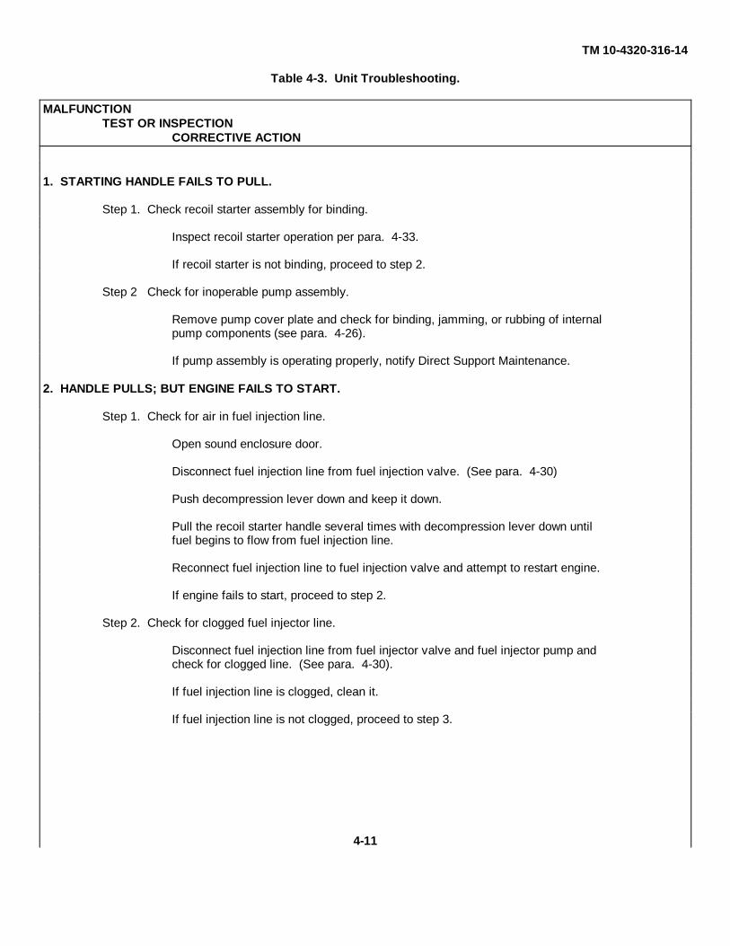
TM 10-4320-316-14
Table 4-3. Unit Troubleshooting.
MALFUNCTIONTEST OR INSPECTION
CORRECTIVE ACTION
1. STARTING HANDLE FAILS TO PULL.
Step 1. Check recoil starter assembly for binding.
Inspect recoil starter operation per para. 4-33.
If recoil starter is not binding, proceed to step 2.
Step 2 Check for inoperable pump assembly.
Remove pump cover plate and check for binding, jamming, or rubbing of internalpump components (see para. 4-26).
If pump assembly is operating properly, notify Direct Support Maintenance.
2. HANDLE PULLS; BUT ENGINE FAILS TO START.
Step 1. Check for air in fuel injection line.
Open sound enclosure door.
Disconnect fuel injection line from fuel injection valve. (See para. 4-30)
Push decompression lever down and keep it down.
Pull the recoil starter handle several times with decompression lever down untilfuel begins to flow from fuel injection line.
Reconnect fuel injection line to fuel injection valve and attempt to restart engine.
If engine fails to start, proceed to step 2.
Step 2. Check for clogged fuel injector line.
Disconnect fuel injection line from fuel injector valve and fuel injector pump andcheck for clogged line. (See para. 4-30).
If fuel injection line is clogged, clean it.
If fuel injection line is not clogged, proceed to step 3.
4-11
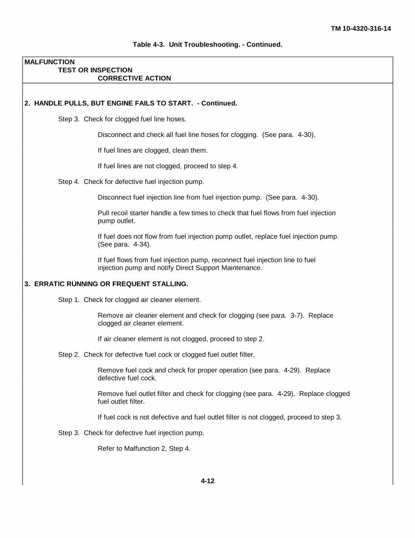
TM 10-4320-316-14
Table 4-3. Unit Troubleshooting. - Continued.
MALFUNCTIONTEST OR INSPECTION
CORRECTIVE ACTION
2. HANDLE PULLS, BUT ENGINE FAILS TO START. - Continued.
Step 3. Check for clogged fuel line hoses.
Disconnect and check all fuel line hoses for clogging. (See para. 4-30).
If fuel lines are clogged, clean them.
If fuel lines are not clogged, proceed to step 4.
Step 4. Check for defective fuel injection pump.
Disconnect fuel injection line from fuel injection pump. (See para. 4-30).
Pull recoil starter handle a few times to check that fuel flows from fuel injectionpump outlet.
If fuel does not flow from fuel injection pump outlet, replace fuel injection pump.(See para. 4-34).
If fuel flows from fuel injection pump, reconnect fuel injection line to fuelinjection pump and notify Direct Support Maintenance.
3. ERRATIC RUNNING OR FREQUENT STALLING.
Step 1. Check for clogged air cleaner element.
Remove air cleaner element and check for clogging (see para. 3-7). Replaceclogged air cleaner element.
If air cleaner element is not clogged, proceed to step 2.
Step 2. Check for defective fuel cock or clogged fuel outlet filter.
Remove fuel cock and check for proper operation (see para. 4-29). Replacedefective fuel cock.
Remove fuel outlet filter and check for clogging (see para. 4-29). Replace cloggedfuel outlet filter.
If fuel cock is not defective and fuel outlet filter is not clogged, proceed to step 3.
Step 3. Check for defective fuel injection pump.
Refer to Malfunction 2, Step 4.
4-12

TM 10-4320-316-14
Table 4-3. Unit Troubleshooting. - Continued.
MALFUNCTIONTEST OR INSPECTION
CORRECTIVE ACTION
If fuel injection pump is not defective, proceed to step 4.
Step 4. Check for clogged exhaust silencer.
If very little air is flowing from engine exhaust, check exhaust silencer per para.4-32. Replace defective exhaust silencer.
If exhaust silencer is not defective, notify Direct Support Maintenance.4. LACK OF POWER.
Refer to Malfunction 3, steps 1, 2, 3, and 4.
5. ENGINE STOPS RUNNING.
Refer to Malfunction 2, steps 1, 2, 3, and 4.
6. PUMP DOES NOT PUMP WATER.
Step 1. Check for broken or misadjusted peeler.
Check peeler for adjustment per para. 4-26.
If peeler is not broken or out of adjustment, proceed to step 2.
Step 2. Check for improper impeller clearance.
Check impeller clearance per para. 4-26.
If impeller clearance is correct, proceed to step 3.
Step 3. Check for damaged pump components or broken pump body.
Replace any damaged pump components per para. 4-26.
If pump body is broken, replace pump unit per para. 4-26.
7. EXCESSIVE LUBRICATION OIL CONSUMPTION.
Inspect engine crankcase for leaks.
Tighten oil drain plug or oil filler cap.
If oil drain plug and oil filler cap are tight, notify Direct Support Maintenance.
4-13

TM 10-4320-316-14
Table 4-3. Unit Troubleshooting. - Continued.
MALFUNCTIONTEST OR INSPECTION
CORRECTIVE ACTION
8. RECOIL STARTER ROPE BINDS.
Step 1. Check for defective recoil starter.
Remove and inspect recoil starter. (See para. 4-33.)
Replace recoil starter if defective.
If recoil starter is not defective, proceed to Step 2.
Step 2. Check for defective pump assembly.
Inspect pump assembly for proper operation. (Refer to para. 4-26.)
If pump assembly is defective, repair or replace it.
If pump assembly is not defective, notify Direct Support Maintenance.
9. ENGINE CRANKSHAFT DOES NOT TURN AS THE ROPE IS PULLED.
Replace recoil starter. (Refer to para. 4-33.)
4-14

TM 10-4320-316-14
SECTION VI. UNIT MAINTENANCE PROCEDURES
4-11. INTRODUCTION. Maintenance procedures at unit level of maintenance include as necessary: removal, cleaningand inspection, repair or replacement, and installation. Unless the procedure requires special resources or tools, morethan one maintenance person or specific equipment conditions, these are not listed for each maintenance procedure.They are listed only for those procedures that require them.
4-15

TM 10-4320-316-14
4-12. IDENT PLATES REPLACEMENT.
This Task Covers:
a. Removal b. Installation
Initial Setup:
Tools RequiredTool Kit, General Mechanic's (Appendix B, Item 1)Bit, Drill, .125 in. dia. (Appendix B, Item 2)Drill, Hand Portable (Appendix B, Item 2)Riveter, Blind, Hand (Appendix B, Item 5)
Material's RequiredNone
Equipment ConditionDED pump assembly shut down and cool.
a. Removal (Refer to Figure 4-1).
NOTEThis procedure describes the replacement of one ident plate. Repeat the procedure asnecessary for all other name plates.
(1) Drill out rivets (1) that holds ident plate (2) onto unit.
(2) Remove ident plate (2) from unit.
b. Installation.
(1) Place ident plate (2) into position on unit and insert two rivets (1).
(2) Install two rivets (1) using hand riveter.
4-16

TM 10-4320-316-14
Figure 4-1. Ident Plates Replacement.
4-17

TM 10-4320-316-14
4-13. ROLL-OVER FRAME REPLACEMENT.
This Task Covers:
a. Removal b. Installation
Initial Setup:
Tools RequiredTool Kit, General Mechanic's (Appendix B, Item 1)
Material's RequiredNone
Equipment ConditionDED pump assembly shut down and cool.
a. Removal (Refer to Figure 4-2).
(1) Remove two screws.(1), two screws (2), and outlet side roll-over frame (3) from unit.
(2) Remove two screws (4), two screws (5), and inlet side roll-over frame (6) from unit.
b. Installation.
(1) Install inlet side roll-over frame (6), two screws (5), and two screw (4).
(2) Install outlet side roll-over frame (3), two screws (2), and two screw (1).
4-18
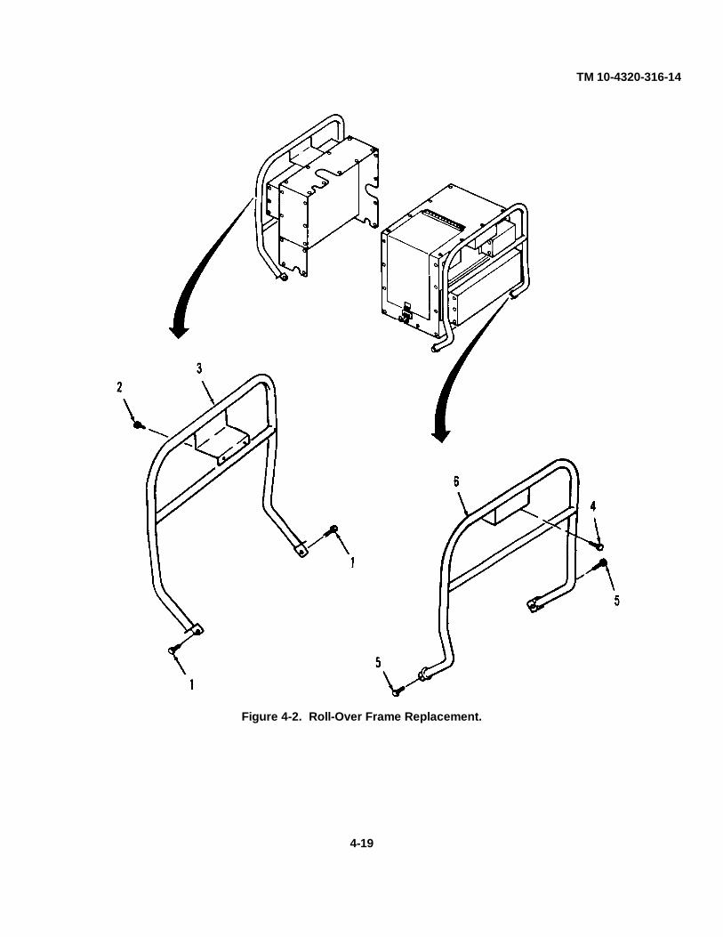
TM 10-4320-316-14
Figure 4-2. Roll-Over Frame Replacement.
4-19
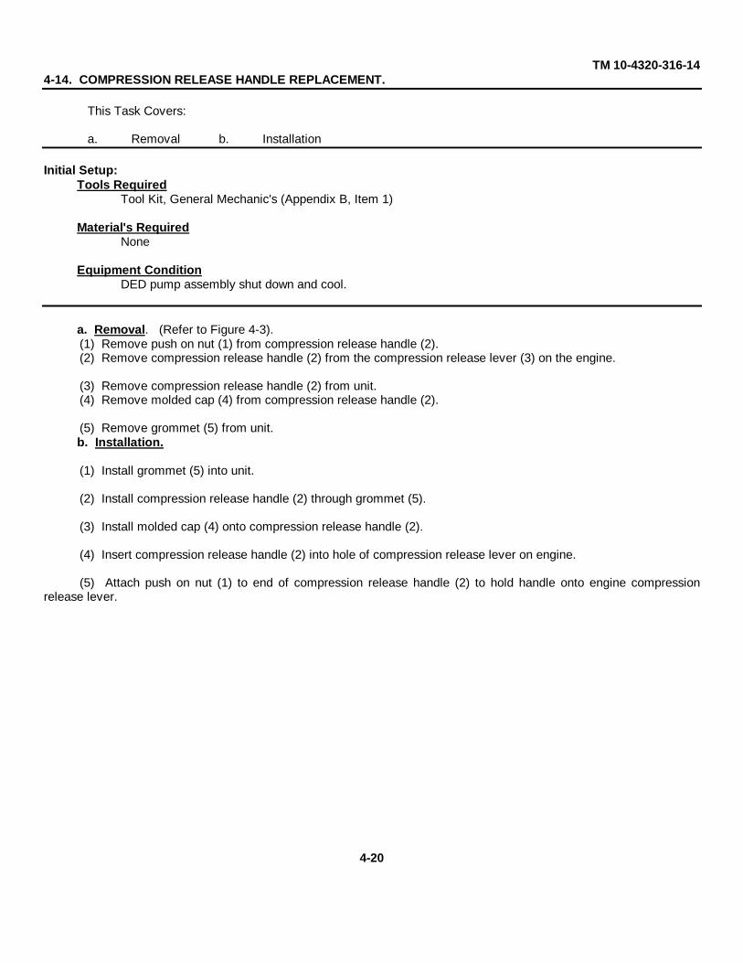
TM 10-4320-316-144-14. COMPRESSION RELEASE HANDLE REPLACEMENT.
This Task Covers:
a. Removal b. Installation
Initial Setup:Tools Required
Tool Kit, General Mechanic's (Appendix B, Item 1)
Material's RequiredNone
Equipment ConditionDED pump assembly shut down and cool.
a. Removal. (Refer to Figure 4-3).(1) Remove push on nut (1) from compression release handle (2).(2) Remove compression release handle (2) from the compression release lever (3) on the engine.
(3) Remove compression release handle (2) from unit.(4) Remove molded cap (4) from compression release handle (2).
(5) Remove grommet (5) from unit.b. Installation.
(1) Install grommet (5) into unit.
(2) Install compression release handle (2) through grommet (5).
(3) Install molded cap (4) onto compression release handle (2).
(4) Insert compression release handle (2) into hole of compression release lever on engine.
(5) Attach push on nut (1) to end of compression release handle (2) to hold handle onto engine compressionrelease lever.
4-20
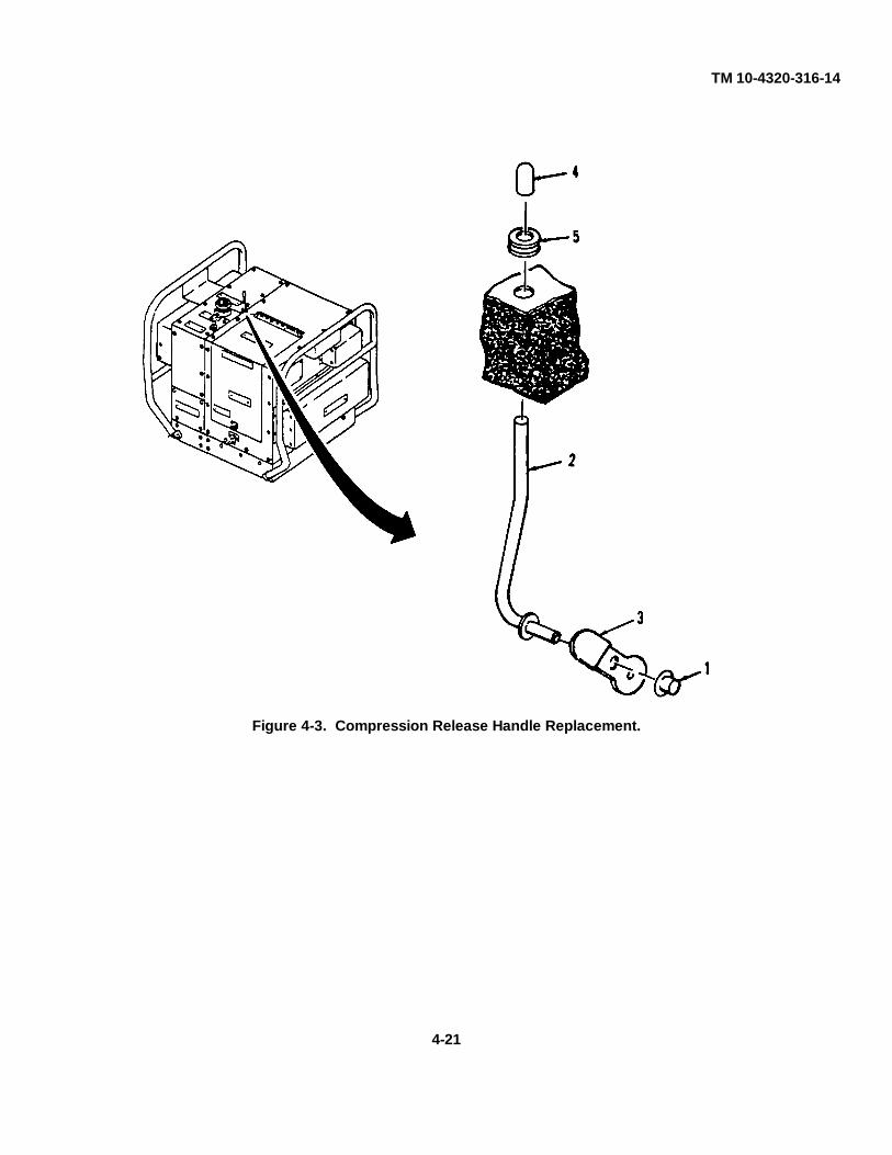
TM 10-4320-316-14
Figure 4-3. Compression Release Handle Replacement.
4-21

TM 10-4320-316-144-15. CONTROL ASSEMBLY REPLACEMENT.
This Task Covers:
a. Removal b. Installation
Initial Setup:
Tools RequiredTool Kit, General Mechanic's (Appendix B, Item 1)
Materials RequiredNone
Equipment ConditionDED pump assembly shut down and cool.Outlet enclosure assembly tilted open (see para 4-23).
a. Removal (Refer to Figure 4-4).
(1) Disconnect end of control assembly (1) from regulator handle (2) on engine.
(2) Loosen nut (3) and slide nut and washer (4) down the length of the control assembly (1) cable and remove nutand washer.
(3) Remove control assembly (1) through top of unit.
b. Installation.NOTE
Be sure throttle handle is fully inserted into cable housing before installing controlassembly into unit.
(1) Feed cable of control assembly (1) through top of unit.
(2) Slide nut (3) and washer (4) up the length of the control assembly cable (1) and install and tighten nut ontocontrol assembly.
(3) Reconnect end of control cable onto regulator handle (2) of engine.
4-22
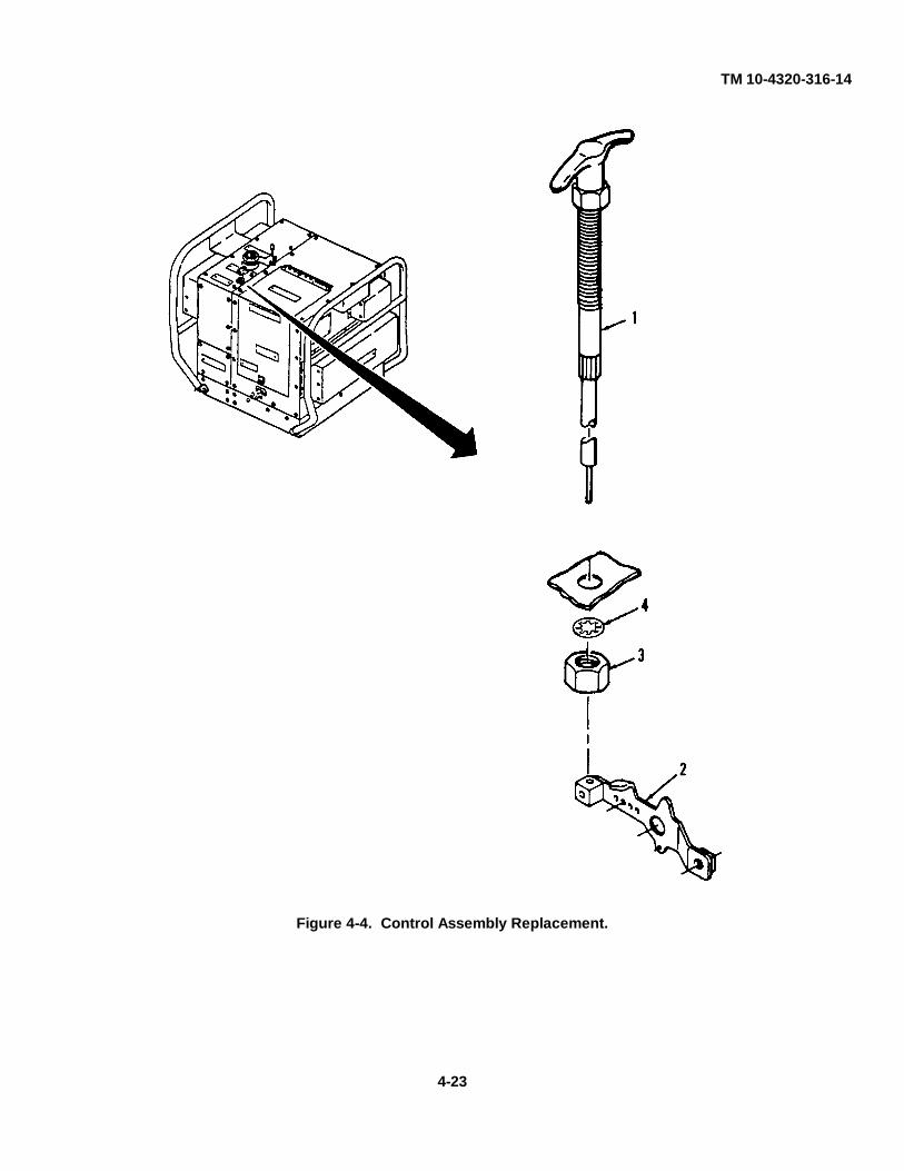
TM 10-4320-316-14
Figure 4-4. Control Assembly Replacement.
4-23
TM 10-4320-316-144-16. AIR INTAKE HOSE REPLACEMENT.
This Task Covers:
a. Removal b. Installation
Initial Setup:
Tools RequiredTool Kit, General Mechanic's (Appendix B, Item 1)
Material's RequiredNone
Equipment ConditionDED pump assembly shut down and cool.
a. Removal. (Refer to Figure 4-5).
(1) Remove air intake hose (1) from intake tube of engine air cleaner.
(2) Remove air intake hose (1) from internal baffle (2).
b. Installation.
(1) Insert end of air intake hose (1) into opening in internal baffle (2).
(2) Attach air intake hose (1) onto inlet tube of engine air cleaner.
4-24

TM 10-4320-316-14
Figure 4-5. Air Intake Hose Replacement.
4-25

TM 10-4320-316-144-17. EXHAUST EXTENSION REPLACEMENT.
This Task Covers:
a. Removal b. Installation
Initial Setup:
Tools RequiredTool Kit, General Mechanic's (Appendix B, Item 1)
Materials RequiredNone
Equipment ConditionDED pump assembly shut down and cool.Outlet enclosure assembly tilted open (see para 4-23).
a. Removal. (Refer to Figure 4-6).
(1) Loosen and remove clamp (1).
(2) Remove exhaust extension (2) from engine.
b. Installation.
(1) Slide clamp (1) onto exhaust extension (2).
(2) Install exhaust extension (2) onto engine exhaust silencer.
(3) Tighten clamp (1) onto exhaust extension (2) to tighten extension onto engine exhaust silencer.
4-26
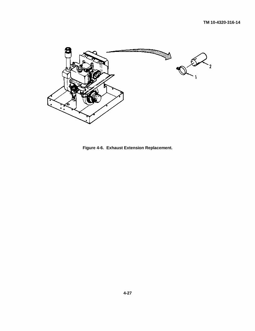
TM 10-4320-316-14
Figure 4-6. Exhaust Extension Replacement.
4-27

TM 10-4320-316-144-18. ACCESS COVER REPAIR AND REPLACEMENT.
This Task Covers:
a. Removal b. Cleaning c. Inspection d. Repair e. Installation
Initial Setup:
Tools RequiredTool Kit, General Mechanic's (Appendix B, Item 1)Shears, Bent, Trimmers (Appendix B, Item 1)Bit, Drill, .125 in. dia. (Appendix B, Item 2)
Materials RequiredCloth, Lint-Free (Appendix E, Item 1)Brush, Medium Bristle (Appendix E, Item 2)Solvent, Dry Cleaning (Appendix E, Item 3)
Equipment ConditionDED pump assembly shut down and cool.
a. Removal. (Refer to Figure 4-7).
(1) Remove four screws (1) from access panel (2).
(2) Remove access panel (2) from unit.
(3) If foam insulation (3) is to be replaced, remove foam insulation (3) from access panel (2).
(4) If access panel is being replaced, drill out two rivets (4) and ident plate (5).
b. Cleaning.
(1) Remove all build up of dirt, oil, and debris from all surfaces.
WARNING
Serious injury can result in breathing fumes of dry cleaning solvent P-D-680, Type III.Serious injury or death can result from explosion of fumes from solvent. When usingthis solvent:
• Clean parts in a well ventilated area.• Avoid inhalation of solvent fumes and prolonged exposure of skin to cleaning solvent. Wash exposed
skin thoroughly.• Do not use near open flame or excessive heat. Flash point of solvent is 100° F to 138° F (38° C to 59°
C).• Wear eye protection when blowing solvent from parts. Air pressure should not exceed 30 psig (2.1
kg/cm2).
(2) Clean all metallic parts with a clean soft cloth or a medium bristle brush, and cleaning solvent. Be sure that allgasket adhesive residue is removed if gasket material is being replaced.
4-28

TM 10-4320-316-14
(3) Allow parts to dry.
c. Inspection. Inspect access cover for cracks or corrosion.
d. Repair. Repair is limited to replacement of parts found defective during inspection.
e. Installation.
(1) Install ident plate (5) and two rivets, if removed.
(2) Install new foam insulation (3) if removed. Refer to Appendix F for manufacturing instructions.
(3) Install access panel (2) and four screws (1) onto unit.
Figure 4-7. Access Cover Repair and Replacement.
4-29

TM 10-4320-316-144-19. PUMP DRAIN REPAIR AND REPLACEMENT.
This Task Covers:
a. Removal b. Inspection c. Repair d. Installation
Initial Setup:
Tools RequiredTool Kit, General Mechanic's (Appendix B, Item 1)
Materials RequiredNone
Equipment ConditionDED pump assembly shut down and cool.Outlet enclosure assembly tilted open (see para 4-23).
a. Removal. (Refer to Figure 4-8).
(1) Remove drain cock (1) from unit.
(2) Remove coupling (2) and nipple (3) from pump (4).
b. Inspection.
(1) Inspect drain cock for damage and for smooth operation of handle.
(2) Check coupling and nipple for cracks and for damaged threads.
c. Repair. Repair is limited to replacement of parts found defective during inspection.
d. Installation.
(1) Install nipple (3) and coupling (2) onto pump (4).
(2) Install drain cock (1) onto coupling (2).
4-30

TM 10-4320-316-14
Figure 4-8. Pump Drain Repair and Replacement.
4-31

TM 10-4320-316-144-20. OIL DRAIN REPAIR AND REPLACEMENT.
This Task Covers:
a. Removal b. Inspection c. Repair d. Installation
Initial Setup:
Tools RequiredTool Kit, General Mechanic's (Appendix B, Item 1)Pan, Drain (Appendix B, Item 2)Shears, Bent, Trimmers (Appendix B, Item 2)
Material's RequiredNone
Equipment ConditionDED pump assembly shut down and cool.Oil drained from engine (see Lubrication Order LO10-4320-316-12).Outlet enclosure assembly tilted open (see para 4-23).
a. Removal. (Refer to Figure 4-9).
(1) Remove plug (1) from hose fitting (2).
(2 Remove hose fitting (3) from engine.
(3) Remove hose fitting (2) and hose fitting (3) from hose (4).
b. Inspection.
(1) Inspect all threads for damage.
(2) Check hose fittings for cracks and damaged threads.
(3) Check hose for cuts and leaks.
c. Repair. Repair is limited to replacement of parts found defective during inspection.
d. Installation.
(1) Install hose fitting (3) and hose fitting (2) onto hose (4).
(2) Install hose fitting (3) into engine.
(3) Install plug (1) into hose fitting (2).
(4) Insert installed plug (1) through enclosure.
4-32

TM 10-4320-316-14
Figure 4-9. Oil Drain Repair and Replacement.
4-33

TM 10-4320-316-144-21. BAFFLES REPLACEMENT.
This Task Covers:
a. Removal b. Installation
Initial Setup:
Tools RequiredTool Kit, General Mechanic's (Appendix B, Item 1)
Materials RequiredNone
Equipment ConditionDED pump assembly shut down and cool.Air intake hose removed (see paragraph 4-16).Outlet enclosure assembly removed (see paragraph 4-23).
a. Removal. (Refer to Figure 4-10).
(1) Remove three screws (1) and muffler baffle assembly (2).
(2) Pull the rope T-handle (3) slowly, turning the crankshaft until approximately two feet of pull rope (4) isexposed.
(3) Grasp the rope (4) firmly and pull the knot (5) in the rope about six inches out of the T-handle (3).
CAUTION
With knot untied do not allow rope to rewind into the starter assembly.
(4) Untie the knot (5) and remove T-handle (3).
(5) Pass the rope (4) through the grommet (6) in baffle (5). Slip the T-handle (3) onto the rope (4) and tie knot (7)in rope.
(6) Allow the rope (4) to rewind until the T-handle (3) seats on the recoil start assembly.
(7) Remove four screws (8) and baffle (5).
4-34

TM 10-4320-316-14
Figure 4-10. Baffles Replacement.
4-35

TM 10-4320-316-144-21. BAFFLES REPLACEMENT. - Continued.
b. Installation
(1) Install baffle (5) and four screws (8).
(2) Pull the rope T-handle (3) slowly, turning the crankshaft until approximately two feet of pull rope (4) isexposed.
(3) Grasp the rope (4) firmly and pull the knot (7) in the rope about six inches out of the T-handle (3).
CAUTION
With knot untied do not allow rope to rewind into the starter assembly.
(4) Untie the knot (7).
(5) Slip the T-handle (3) off of the rope (4) and retie the knot.
(6) Feed the rope (4) through the baffle grommet (6).
(7) Install T-handle (3) on the rope (4). Thread enough rope through the T-handle to make knot (5).
(8) Pull rope (4) against the hole in the T-handle (3). Stuff excess rope into the T-handle slot.
(9) Install muffler baffle assembly (2) and three screws (1).
4-36/(4-37 Blank)
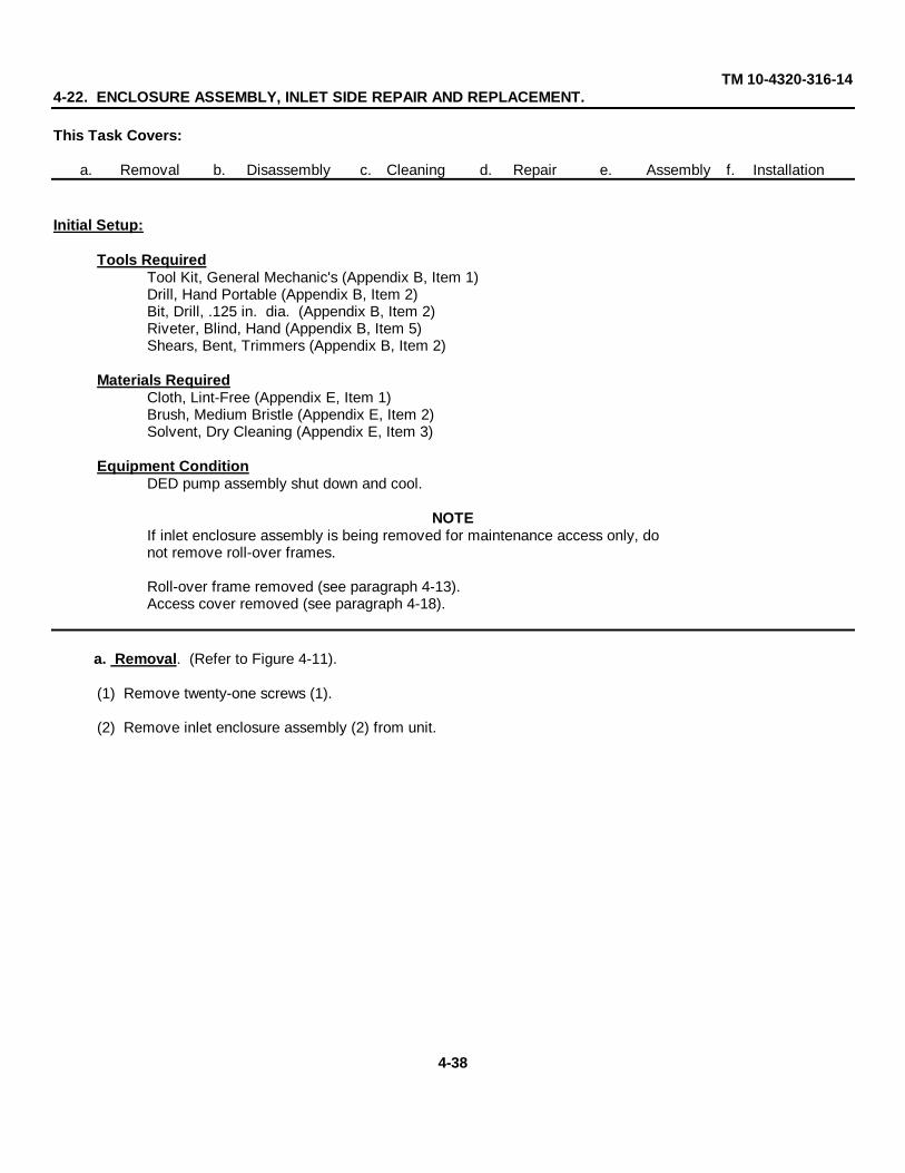
TM 10-4320-316-144-22. ENCLOSURE ASSEMBLY, INLET SIDE REPAIR AND REPLACEMENT.
This Task Covers:
a. Removal b. Disassembly c. Cleaning d. Repair e. Assembly f. Installation
Initial Setup:
Tools RequiredTool Kit, General Mechanic's (Appendix B, Item 1)Drill, Hand Portable (Appendix B, Item 2)Bit, Drill, .125 in. dia. (Appendix B, Item 2)Riveter, Blind, Hand (Appendix B, Item 5)Shears, Bent, Trimmers (Appendix B, Item 2)
Materials RequiredCloth, Lint-Free (Appendix E, Item 1)Brush, Medium Bristle (Appendix E, Item 2)Solvent, Dry Cleaning (Appendix E, Item 3)
Equipment ConditionDED pump assembly shut down and cool.
NOTEIf inlet enclosure assembly is being removed for maintenance access only, donot remove roll-over frames.
Roll-over frame removed (see paragraph 4-13).Access cover removed (see paragraph 4-18).
a. Removal. (Refer to Figure 4-11).
(1) Remove twenty-one screws (1).
(2) Remove inlet enclosure assembly (2) from unit.
4-38

TM 10-4320-316-14
Figure 4-11. Enclosure Assembly, Inlet Side Removal.
b. Disassembly. (Refer to Figure 4-12).
(1) Drill out and remove four rivets (1) from door (2).
(2) Drill out and remove four rivets (1) and remove hinge (3).
(3) Drill out and remove two rivets (4) and two rivets (5).
(4) Remove catch strike (6) and clamping catch (7) from door (2).
(5) Drill out and remove ten rivets (8) and sheet (9) from sheet (10).
(6) Drill out and remove seven rivets (11) and sheet (12) from sheet (9).
(7) Drill out and remove eight rivets (13) and sheet (14) from sheet (9).
(8) If foam insulation is to be replaced, remove foam insulation as required.
4-39
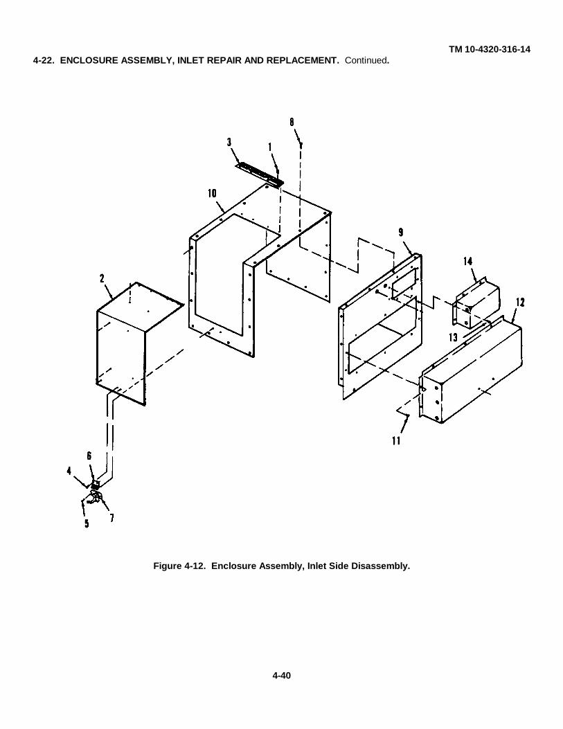
TM 10-4320-316-144-22. ENCLOSURE ASSEMBLY, INLET REPAIR AND REPLACEMENT. Continued.
Figure 4-12. Enclosure Assembly, Inlet Side Disassembly.
4-40

TM 10-4320-316-14c. Cleaning.
(1) Remove all build up of dirt, oil, and debris from all surfaces.
WARNING
Serious injury can result in breathing fumes of dry cleaning solvent P-D-680, Type III.Serious injury or death can result from explosion of fumes from solvent. When usingthis solvent:
• Clean parts in a well ventilated area.• Avoid inhalation of solvent fumes and prolonged exposure of skin to cleaning solvent. Wash exposed
skin thoroughly.• Do not use near open flame or excessive heat. Flash point of solvent is 100° F to 138° F (38° C to 59°
C).• Wear eye protection when blowing solvent from parts. Air pressure should not exceed 30 psig (2.1
kg/cm2).
(2) Clean all metallic parts with a clean soft cloth or a medium bristle brush, and cleaning solvent. Be sure that allgasket adhesive residue is removed if gasket material is being replaced.
(3) Allow parts to dry.
d. Repair. Repair is limited to replacement of parts found defective during inspection.
e. Assembly. (Refer to Figure 4-12.)
(1) If foam insulation was removed, replace foam insulation. Refer to Appendix F for manufacturing instructions.
(2) Install eight rivets (13) and sheet (14) onto sheet (9).
(3) Install seven rivets (11) and sheet (12) onto sheet (9).
(4) Install ten rivets (8) and sheet (9) onto sheet (10).
(5) Install two rivets (5) and clamping catch onto sheet (10).
(6) Install two rivets (4) and catch strike (6) onto door (2).
(7) Install four rivets (1) and hinge (3) onto door (2).
(8) Install four rivets (1) and door (2) onto sheet (10).
f. Installation. (Refer to Figure 4-11).
(1) Place inlet enclosure assembly (2) into position on unit.
(2) Install twenty-one screws (1).
4-41

TM 10-4320-316-144-23. ENCLOSURE ASSEMBLY, OUTLET REPAIR AND REPLACEMENT.
This Task Covers:
a. Removal b. Disassembly c. Cleaning d. Repair e. Assembly f. Installation
Initial Setup:
Tools RequiredTool Kit, General Mechanic's (Appendix B, Item 1)Drill, Hand Portable (Appendix B, Item 2)Riveter, Blind, Hand (Appendix B, Item 5)Bit, Drill, .125 in. dia. (Appendix B, Item 2)Shears, Bent, Trimmers (Appendix B, Item 2)
Material's RequiredCloth, Lint-Free (Appendix E, Item 1)Brush, Medium Bristle (Appendix E, Item 2)Solvent, Dry Cleaning (Appendix E, Item 3)
Equipment ConditionDED pump assembly shut down and cool.
NOTEIf outlet enclosure assembly is being removed for maintenance access only, donot remove roll-over frames.
Roll-over handles removed (see paragraph 4-13).Access cover removed (see paragraph 4-18).Inlet enclosure assembly removed (see paragraph 4-22).Compression release handle removed (see paragraph 4-14).Throttle control assembly removed (see paragraph 4-15).
a. Removal. (Refer to Figure 4-13).
(1) Remove nineteen screws (1).
(2) Remove outlet enclosure assembly (2) from unit.
(3) Remove four screws (3) and sheet (4).
4-42

TM 10-4320-316-14
Figure 4-13. Enclosure Assembly, Outlet Side Removal.
b. Disassembly. (Refer to Figure 4-14).
(1) Drill out and remove seven rivets (1).
(2) Remove sheet (2) from sheet (3).
(3) Drill out and remove eleven rivets (4).
(4) Remove sheet (5) from sheet (3).
(5) If foam insulation is to be replaced, remove foam insulation (6) as required.
4-43
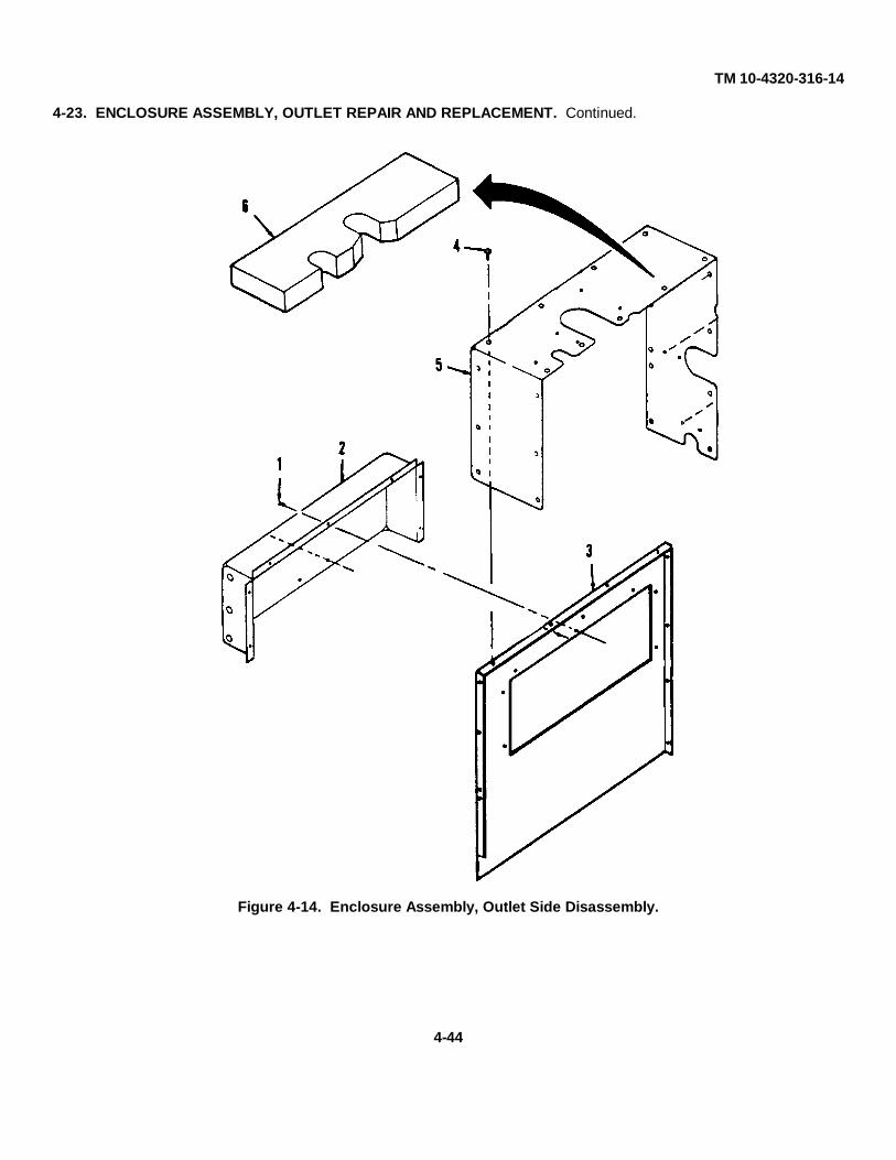
TM 10-4320-316-14
4-23. ENCLOSURE ASSEMBLY, OUTLET REPAIR AND REPLACEMENT. Continued.
Figure 4-14. Enclosure Assembly, Outlet Side Disassembly.
4-44
TM 10-4320-316-14c. Cleaning.
(1) Remove all build up of dirt, oil, and debris from all surfaces.
WARNING
Serious injury can result in breathing fumes of dry cleaning solvent P-D-680, Type III.Serious injury or death can result from explosion of fumes from solvent. When usingthissolvent:
• Clean parts in a well ventilated area.• Avoid inhalation of solvent fumes and prolonged exposure of skin to cleaning solvent. Wash exposed
skin thoroughly.• Do not use near open flame or excessive heat. Flash point of solvent is 100° F to 138° F (38° C to 59°
C).• Wear eye protection when blowing solvent from parts. Air pressure should not exceed 30 psig (2.1
kg/cm2).
(2) Clean all metallic parts with a clean soft cloth or a medium bristle brush, and cleaning solvent. Be sure that allgasket adhesive residue is removed if gasket material is being replaced.
(3) Allow parts to dry.
d. Repair. Repair is limited to replacement of parts found defective during inspection.
e. Assembly. (Refer to Figure 4-14.)
(1) If foam insulation (6) was removed, replace foam insulation. Refer to Appendix F for manufacturinginstructions.
(2) Place sheet (5) into position on sheet (3) and install eleven rivets (4).
(3) Place sheet (2) into position on sheet (3) and install seven rivets (1).
f. Installation. (Refer to Figure 4-13).
(1) Install sheet (4) and four screws (3).
(2) Place outlet enclosure assembly (3) into position on unit and install twelve screws (2).
(3) Install seven screws (1).
(4) Install access cover (see paragraph 4-18).
(5) Install roll-over frames (see paragraph 4-13).
4-45

TM 10-4320-316-144-24. PUMP INLET/OUTLET PIPING AND SUCTION FLANGE ASSEMBLY REPAIR AND
REPLACEMENT.
This Task Covers:
a. Removal b. Cleaning c. Inspection d. Repair e. Installation
Initial Setup:
Tools RequiredTool Kit, General Mechanic's (Appendix B, Item 1)
Materials RequiredCloth, Lint-Free (Appendix E, Item 1)Brush, Medium Bristle (Appendix E, Item 2)Solvent, Dry Cleaning (Appendix E, Item 3)Detergent, General Purpose (Appendix E, Item 10)Tape Anti-seize (Appendix E, Item 11)Gasket, (Refer to TM10-4320-316-24P)
Equipment ConditionDED pump assembly shut down and cool.Inlet enclosure removed (see paragraph 4-22).Outlet enclosure removed (see paragraph 4-23).
a. Removal (Refer to Figure 4-15)
(1) Remove hose adapter (1), coupling (2), and nipple (3) from pump (4) inlet.
(2) Remove hose adapter (5), gasket (6), coupling (7), and nipple (8) from pump (9) outlet.
(3) Remove two nuts (10) and two lock washers (11) from pump assembly (12).
(4) Remove suction flange (13) and gasket (14) from pump assembly (12).
(5) Remove screw (15), check valve weight (16), and check valve weight (17) from gasket (18).Discard gasket.
b. Cleaning.
(1) Remove all build up of dirt, oil, and debris from all surfaces.
WARNING
Serious injury can result in breathing fumes of dry cleaning solvent P-D-680, Type III.Serious injury or death can result from explosion of fumes from solvent. When using thissolvent:
• Clean parts in a well ventilated area.• Avoid inhalation of solvent fumes and prolonged exposure of skin to cleaning solvent. Wash exposed
skin thoroughly.• Do not use near open flame or excessive heat. Flash point of solvent is 100° F to 138° F (38° C to 59°
C).• Wear eye protection when blowing solvent from parts. Air pressure should not exceed 30 psig (2.1
kg/cm2).
4-46

TM 10-4320-316-14
(2) Clean all metallic parts with a clean soft cloth or a medium bristle brush, and cleaning solvent.
(3) Allow parts to dry.
c. Inspection.
(1) Inspect all threads for damage.
(2) Check hose adapters, couplings, and nipples for cracks.
Figure 4-15. Pump Inlet/Outlet Piping Repair and Suction Flange Assembly Repairand Replacement.
4-47

TM 10-4320-316-14
4-24. PUMP INLET/OUTLET PIPING AND SUCTION FLANGE ASSEMBLY REPAIR ANDREPLACEMENT. - Continued.
d. Repair. Repair is limited to replacement of parts found defective during inspection.
e. Installation.
(1) Install check valve weight (17), check valve weight (16), and screw (15) onto new gasket (18).
NOTEHinged area of gasket faces the top stud. Large weight should face the pump.
NOTEInstall suction flange with tapered, protruding edge facing bottom.
(2) Install gasket (14), suction flange (13), two lock washers (11), and two nuts (10) onto pump (12).
NOTEAlways wrap anti-seize tape around threads in the same direction as threads will rotate during installation.
(3) Wrap anti-seize tape around pipe threads and install nipple (8), coupling (7), gasket (6), and hose adapter (5) ontopump (9) outlet.
(4) Wrap anti-seize tape around pipe threads and install nipple (3), coupling (2), and hose adapter (1) onto pump (4)inlet.
4-48/(4-49 Blank)

TM 10-4320-316-14
4-25. BOTTOM PAN FRAME REPAIR AND REPLACEMENT.
This Task Covers:
a. Removal b. Cleaning c. Inspection d. Repair e. Installation
Initial Setup:Tools Required
Tool Kit, General Mechanic's (Appendix B, Item 1)Material's Required
Cloth, Lint-Free (Appendix E, Item 1)Brush, Medium Bristle (Appendix E, Item 2)Solvent, Dry Cleaning (Appendix E, Item 3)
Equipment ConditionDED pump assembly shut down and cool.Inlet enclosure removed (see paragraph 4-22).Outlet enclosure removed (see paragraph 4-23).
a. Removal (Refer to Figure 4-16).
(1) Remove four screws (1), eight shock mounts (2), four flat washers (3), and four lock nuts (4).(2) Remove bottom pan frame (5).(3) Remove four screws (13), four flat washers (14), and four bumpers (15) from bottom pan frame
(5).
b. Cleaning.(1) Remove all build up of dirt, oil, and debris from all surfaces.
WARNING
Serious injury can result in breathing fumes of dry cleaning solvent P-D-680, Type III. Serious injury ordeath can result from explosion of fumes from solvent. When using this solvent:
Clean parts in a well ventilated area.
Avoid inhalation of solvent fumes and prolonged exposure of skin to cleaning solvent. Washexposed skin thoroughly.
Do not use near open flame or excessive heat. Flash point of solvent is 100° F to 138° F (38° Cto 59° C).
Wear eye protection when blowing solvent from parts. Air pressure should not exceed 30 psig (2.1 kg/cm2).
(2) Clean all metallic parts with a clean soft cloth or a medium bristle brush, and cleaning solvent.
(3) Allow parts to dry.
4-50

TM 10-4320-316-14
Figure 4-16. Bottom Pan Frame Repair and Replacement.4-51

TM 10-4320-316-14
4-25. BOTTOM PAN FRAME REPAIR AND REPLACEMENT. - Continued.c. Inspection.
(1) Inspect all fastener threads for damage.(2) Check bottom pan frame for cracks and dents.
(3) Inspect bumpers and shock for damage.
d. Repair. Repair is limited to replacement of parts found defective during inspection.
e. Installation.
(1) Install four bumpers (15), four flat washers (14), and four screws (13), onto bottom pan frame (5).
(2) Install bottom pan frame (5).
(3) Install four lock nuts (4), four flat washers (3), eight shock mounts (2) and four screws (1).
4-52/(4-53 Blank)

TM 10-4320-316-14
4-26. PUMP ASSEMBLY REPAIR AND REPLACEMENT.
This Task Covers:
a. Removal b. Cleaning c. Inspection d. Repair e. Installation
Initial Setup:Tools Required
Tool Kit, General Mechanic's (Appendix B, item 1)
Material's RequiredDetergent, General Purpose (Appendix E, Item 10)Cloth, Lint-Free (Appendix E, Item 1)Brush, Medium Bristle (Appendix E, Item 2)Silicone Compound (Appendix E, Item 4)Packing, (Refer to TM 10-4320-316-24P)Lock Washer (Refer to TM 10-4320-316-24P)Lock Washers (Refer to TM 10-4320-316-24P)
Equipment ConditionDED pump assembly shut down and cool.Outlet enclosure assembly tilted open (see paragraph 4-23).
a. Removal. (Refer to Figure 4-17).
(1) Remove two shoulder bolts (1), cover plate (2), and packing (3). Discard packing.
(2) Remove nut (4), setscrew (5), and plastic washer (6).
(3) Remove peeler (7) from pump.
(4) Remove screw (8), lock washer (9), and washer (10). Discard lock washer.
NOTEIt may be necessary to use a small wood block and the rubber mallet to tap the impellervanes so impeller breaks loose.
(5) Remove impeller (11)
(6) Remove three screws (12), and wear plate (13).
(7) Tap out adapter shaft (14), two keys (15), and O-ring (16).
(8) Remove shim stock (17).
(9) Remove three screws (18), three lock washers (19), and pump body (20) from engine. Discard lock washers.
(10) Remove plug (21) from pump body (20).
(11) Remove two studs (22) from pump body (20).
4-54

TM 10-4320-316-14
NOTEDo not remove shaft seal unless it is being replaced.
(12) Tap out shaft seal (23)
Figure 4-17. Pump Assembly Repair and Replacement.
4-55
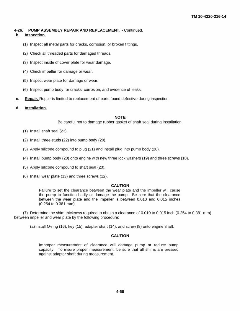
TM 10-4320-316-14
4-26. PUMP ASSEMBLY REPAIR AND REPLACEMENT. - Continued.b. Inspection.
(1) Inspect all metal parts for cracks, corrosion, or broken fittings.
(2) Check all threaded parts for damaged threads.
(3) Inspect inside of cover plate for wear damage.
(4) Check impeller for damage or wear.
(5) Inspect wear plate for damage or wear.
(6) Inspect pump body for cracks, corrosion, and evidence of leaks.
c. Repair. Repair is limited to replacement of parts found defective during inspection.
d. Installation.
NOTEBe careful not to damage rubber gasket of shaft seal during installation.
(1) Install shaft seal (23).
(2) Install three studs (22) into pump body (20).
(3) Apply silicone compound to plug (21) and install plug into pump body (20).
(4) Install pump body (20) onto engine with new three lock washers (19) and three screws (18).
(5) Apply silicone compound to shaft seal (23).
(6) Install wear plate (13) and three screws (12).
CAUTIONFailure to set the clearance between the wear plate and the impeller will causethe pump to function badly or damage the pump. Be sure that the clearancebetween the wear plate and the impeller is between 0.010 and 0.015 inches(0.254 to 0.381 mm).
(7) Determine the shim thickness required to obtain a clearance of 0.010 to 0.015 inch (0.254 to 0.381 mm)between impeller and wear plate by the following procedure:
(a) Install O-ring (16), key (15), adapter shaft (14), and screw (8) onto engine shaft.
CAUTION
Improper measurement of clearance will damage pump or reduce pumpcapacity. To insure proper measurement, be sure that all shims are pressedagainst adapter shaft during measurement.
4-56

TM 10-4320-316-14
Figure 4-18. Measuring Impeller Clearance.(b) (Refer to Figure 4-18. ) Position a straight edge across the surface of the wear plate (13) and install single .
010 shims onto shoulder of adapter shaft until the straight edge comes into contact with the edge of a shim when thestraight edge is slid across the wear plate surface and against the adapter shaft.
(c) Remove one .010 shim and replace with one .005 shim and repeat Step (b). If straight edge does not touchthe edge of the .005 shim, remove the .005 shim and install two .010 shims. This will provide a clearance of about .015in. If the straight edge does touch the edge of the .005 shim, remove .005 shim and replace it with one .010 shim. Thiswill provide about .010 clearance.
(d) When clearance is correct, remove screw (1), washer (10), and lock washer (9). Then install impeller (11),washer (10), new lock washer (9), and screw (8).
(8) Install peeler (7) into pump.
(9) Install plastic washer (6), set screw (5), and nut (4).
(10) Adjust the peeler by performing the following steps.
4-57
TM 10-4320-316-14
4-26. PUMP ASSEMBLY REPAIR AND REPLACEMENT. - Continued.
d. Installation. - Continued.
CAUTIONImproper adjustment of peeler will cause damage to pump or reduce pump capacity. Be surefeeler gauge is placed between peeler and one of the blades of the impeller.
(a) Loosen nut (4) and set screw (5) and use a feeler gauge to adjust gap between peeler (7) and impeller untilgap is 0.015 in. (0.381 mm).
(b) Tighten set screw (5) and then tighten nut (4).
(11) Apply silicone compound to packing (3).
(12) Install new packing (3), cover plate (2), and two shoulder bolts (1) onto pump.
4-58/(4-59 Blank)

TM 10-4320-316-14
4-27. FUEL TANK ASSEMBLY REPAIR AND REPLACEMENT.
This Task Covers:
a. Removal b. Cleaning c. Inspection d. Repair e. Installation
Initial Setup: WARNINGImproper care in handling fuel can
Tools Required cause fire and explosion which canTool Kit, General Mechanic's (Appendix B, Item 1) cause severe injury or death toPan, Drain (Appendix B, Item 2) operating personnel. To avoid fire
or explosion during engineMaterials Required refueling:
Cloth, Lint-Free (Appendix E, Item 1)DO NOT allow any flame
Equipment Condition producing material within 50DED pump assembly shut down and cool. feet (15.25 m) of fuel duringOutlet enclosure removed (see paragraph 4-23). equipment filling.
DO NOT smoke while refueling.DO NOT let fuel drip onto anyhot surface.DO NOT overfill fuel tank.DO NOT refuel unit whileengine is running.
a. Removal (Refer to Figure 4-19).
(1) Remove fuel cap (1) and drain plug (2) located at the bottom right corner of the fuel tank (3) and drain out all fuelinto a clean container. Dispose of fuel per FM 10-69.
(2) Release hose clamps (4) on overflow hose (5).
(3) Release hose clamp (6) on fuel line (7) at injection pump (8) and disconnect hose from fuel tank (3).
(4) Remove hex head screw (9), lifting bolt (10), and washer (11) securing the upper part of the fuel tank staybracket (12) and remove stay bracket and two dampers (13).
(5) Remove fuel tank (3).
(6) Remove two clamps (14) and pipe fuel gauge (15).
(7) Remove two bolts (16), stay (17), and two dampers (18).
b. Cleaning.
(1) Wipe outside of fuel tank with clean, dry, lint-free cloth to remove any oil or grease deposits.
(2) When tank is completely clean of any residual fuel, remove cap and clean away any deposits.
4-60

TM 10-4320-316-14
Figure 4-19. Fuel Tank Assembly Repair and Replacement.
4-61

TM 10-4320-316-14
4-27. FUEL TANK ASSEMBLY REPAIR AND REPLACEMENT. - Continued.
c. Repair.
Repair is limited to replacement of defective parts.
d. Installation.
(1) Install two dampers (18), stay (17), and two bolts (16).
(2) Install pipe fuel gauge (15) and two clamps (14).
(3) Attach fuel tank (3) using two dampers (13), upper stay bracket (12), washer (11), lifting bolt (10), and hexhead screw (9).
(4) Connect fuel line hose (7) and hose clamp (6) to fuel tank (3) and then connect other end of hose to injectionpump (8).
(5) Connect overflow hose (5) and clamp (4) to fuel tank (3).
(6) Replace drain plug (2) and fuel cap (1).
(7) Check carefully for any leaks when filling the fuel tank.
4-62/(4-63 Blank)
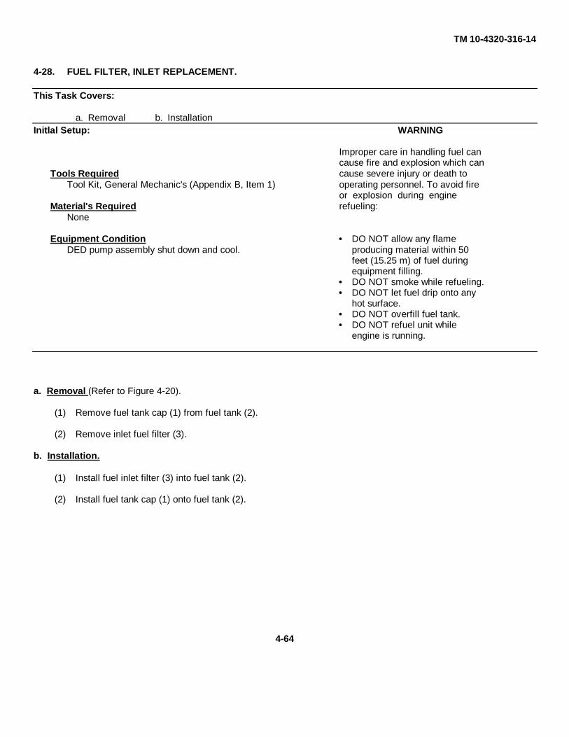
TM 10-4320-316-14
4-28. FUEL FILTER, INLET REPLACEMENT.
This Task Covers:
a. Removal b. InstallationInitlal Setup: WARNING
Improper care in handling fuel cancause fire and explosion which can
Tools Required cause severe injury or death toTool Kit, General Mechanic's (Appendix B, Item 1) operating personnel. To avoid fire
or explosion during engineMaterial's Required refueling:
None
Equipment Condition DO NOT allow any flameDED pump assembly shut down and cool. producing material within 50
feet (15.25 m) of fuel duringequipment filling.DO NOT smoke while refueling.DO NOT let fuel drip onto anyhot surface.DO NOT overfill fuel tank.DO NOT refuel unit whileengine is running.
a. Removal (Refer to Figure 4-20).
(1) Remove fuel tank cap (1) from fuel tank (2).
(2) Remove inlet fuel filter (3).
b. Installation.
(1) Install fuel inlet filter (3) into fuel tank (2).
(2) Install fuel tank cap (1) onto fuel tank (2).
4-64

TM 10-4320-316-14
Figure 4-20. Fuel Filter, Inlet Replacement.
4-65

TM 10-4320-316-14
4-29. FUEL COCK AND FUEL FILTER, OUTLET REPLACEMENT.
This Task Covers:a. Removal b Service c. Installation
Initial Setup: WARNINGImproper care in handling fuel can
Tools Required cause fire and explosion which canTool Kit, General Mechanic's (Appendix B, Item 1) cause severe injury or death toPan, Drain (Appendix B, Item 2) operating personnel. To avoid fire
or explosion during engineMaterial's Required refueling:
Diesel Fuel (Appendix E, Item 6)O-ring, (Refer to TM10-4320-316-24P) DO NOT allow any flame
producing material within 50Equipment Condition feet (15.25 m) of fuel during
DED pump assembly shut down and cool. equipment filling.DO NOT smoke while refueling.DO NOT let fuel drip onto any
hot surface.DO NOT overfill fuel tank.DO NOT refuel unit whileengine is running.
a. Removal (Refer to Figure 4-21).
(1) Remove fuel tank cap (1) and strainer (2).
(2) Drain all fuel from fuel tank (3) by removing drain plug (4) at bottom of the tank. Dispose of fuel per FM 10-69.
(3) Loosen clamp (5) and remove fuel line hose (6) from fuel cock (7).
(4) Remove nut (8), nut (9), and washer (10) securing the fuel cock to studs on the tank, and remove fuel cock (7).
(5) Remove O-ring (11) from fuel cock (7). Discard O-ring.
(6) Remove fuel filter (12) and gasket (13) from inside of fuel tank (3).
b. Service.
(1) Wash the fuel cock (7) and filter (12) thoroughly with diesel fuel.
(2) Check the filter (12) for cracks or damage. Replace damaged filter.
(3) Dry fuel cock (7) thoroughly before reinstalling.
c. Installation.
(1) Insert fuel filter (12) and new gasket (13) into fuel tank (3) through fuel tank cap (1) opening and position thefuel filter studs through the holes in the bottom of the fuel tank.
4-66

TM 10-4320-316-14
(2) Position fuel cock (7) with a new O-ring (11) over the two studs. Be sure that the shut off handle on the fuelcock points away from the engine.
(3) Install washer (10), nut (9), and nut (8) onto fuel cock (7).
(4) Replace fuel line hose (6) and clamp (5) onto fuel cock (7).
(5) Install drain plug (4).
(6) Replace strainer (2) and fuel tank cap (1) onto fuel tank (3).
(7) Check for leaks after refilling. Tighten any loose fasteners or clamps causing leaks.
Figure 4-21. Fuel Cock and Fuel Filter, Outlet Replacement.4-67

TM 10-4320-316-14
4-30. FUEL LINES REPLACEMENT.
This Task Covers:a. Removal b Service c. Installation
Initial Setup: WARNINGTools Required Improper care in handling fuel can
Tool Kit, General Mechanic's (Appendix B, Item 1) cause fire and explosion which canPan, Drain (Appendix B, Item 2) cause severe injury or death to
operating personnel. To avoid fireMaterial's Required or explosion during engine
Cloth, Lint Free (Appendix E, Item 1) refueling:Diesel Fuel (Appendix E, Item 6)
DO NOT allow any flameEquipment Condition producing material within 50
DED pump assembly shut down and cool. feet (15.25 m) of fuel duringInlet enclosure removed (see paragraph 4-22). equipment filling.Outlet enclosure removed (see paragraph 4-23) DO NOT smoke while refueling.
DO NOT let fuel drip onto anyhot surfaceDO NOT overfill fuel tank.DO NOT refuel unit while
engine is running.
a. Removal (Refer to Figure 4-22).
(1) Drain all fuel from fuel tank (1) by removing drain plug (2) at bottom of the tank. Dispose of fuel per FM 10-69.
(2) Turn fuel cock (5) to OFF position.
(3) Loosen connectors (6) at each end of fuel injection pipe (7).
(4) Remove fuel injection pipe (7).
(5) Remove two clamps (8), hose (9), two hose bands (10), and hose (11).
(6) Wipe up any fuel that has leaked during removal
b. Cleaning.
Thoroughly wash the fuel injection pipe (6) in diesel fuel. Insure that line is clear. Wipe with clean, lint-free cloth.
c. Installation.
(1) Install hose (11), two hose bands (10), hose (9), and two clamps (8).
(2) Position fuel injection pipe (7) between fuel injection nozzle and fuel injection pump. Position the pipe so thatthe fittings line up.
(3) Carefully hand tighten connectors (6) on fuel injection pipe (7). Finish tightening the two connectors with awrench taking care not to strip the fittings.
4-68
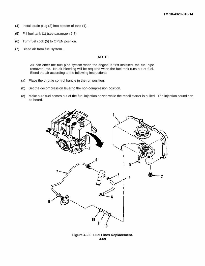
TM 10-4320-316-14
(4) Install drain plug (2) into bottom of tank (1).
(5) Fill fuel tank (1) (see paragraph 2-7).
(6) Turn fuel cock (5) to OPEN position.
(7) Bleed air from fuel system.
NOTE
Air can enter the fuel pipe system when the engine is first installed, the fuel piperemoved, etc. No air bleeding will be required when the fuel tank runs out of fuel.Bleed the air according to the following instructions:
(a) Place the throttle control handle in the run position.
(b) Set the decompression lever to the non-compression position.
(c) Make sure fuel comes out of the fuel injection nozzle while the recoil starter is pulled. The injection sound canbe heard.
Figure 4-22. Fuel Lines Replacement.4-69

TM 10-4320-316-14
4-31. AIR CLEANER, FILTER ELEMENT, AND AIR INTAKE PIPE REPAIR AND REPLACEMENT.
This Task Covers:
a. Removal b. Inspection c. Repair. d. InstallationInitial Setup:
Tools RequiredTool Kit, General Mechanic's (Appendix B, Item 1)
Material's RequiredGasket, (Refer to TM10-4320-316-24P)Gasket, (Refer to TM10-4320-316-24P)
Equipment ConditionDED pump assembly shut down and cool.Cooling fan housing removed (see paragraph 4-33).
a. Removal (Refer to Figure 4-23).
(1) Loosen and remove wing nut (1) and washer (2).
(2) Remove air cleaner housing cover (3).
(3) Remove air cleaner element (4).
(4) Remove three hex nuts (5) securing the air cleaner housing (6).
(5) Remove air cleaner housing (6). Discard gasket (7).
(6) Remove hex bolt (8) and air intake pipe (9) and air intake gasket (10). Discard gasket (10).
b. Inspection.
(1) Check that air cleaner housing (6) and cover (3) are free from dirt.
(2) Check air cleaner housing (6) and cover (3) for damage. Replace if necessary.
c. Repair.
Repair is limited to replacement of defective parts.
d. Installation.
CAUTIONNever run the engine without the air cleaner element. Rapid engine wear mayresult.
(1) Place new gasket (10) in place, position air intake bend (9), and secure with hex bolt (8).
(2) Place new gasket (7) on intake manifold studs.
4-70

TM 10-4320-316-14
(3) Place air cleaner housing (6) over studs and secure with three hex nuts (5).
(4) Install air cleaner element (4) into air cleaner housing (6).
(5) Replace air cleaner housing cover (3).
(6) Replace and tighten washer (2) and wing nut (1).
Figure 4-23. Air Cleaner, Filter Element, and Air Intake Pipe Repair and Replacement.
4-71
TM 10-4320-316-14
4-32. EXHAUST SILENCER REPAIR AND REPLACEMENT.
This Task Covers:
a. Removal b. Inspection c. Repair. d. Installation
Initial Setup:
Tools RequiredTool Kit, General Mechanic's (Appendix B, Item 1)
Material's RequiredGasket, (Refer to TM10-4320-316-24P)
Equipment ConditionDED pump assembly shut down and cool.Muffler baffle assembly removed (see paragraph 4-21).
a. Removal (Refer to Figure 4-24).
(1) Remove two hex head nuts (1) securing the exhaust silencer (2) to studs on the exhaust port of the engine.
(2) Remove two hex head screws (3) securing the bracket on exhaust silencer (2) to the rear of the engine.
(3) Lift exhaust silencer (2) and gasket (4) from the studs. Discard gasket.
b. Inspection.
Carefully inspect exhaust silencer (2) for cracks, rust, or pin holes.
c. Repair.
Repair is limited to replacement of defective parts.
d. Installation.
(1) Position exhaust silencer (2) and new gasket (4) onto the studs and line up holds in bracket with rear mountingholes on engine.
(2) Secure exhaust silencer (2) with two hex head nuts (1) onto the studs and two hex head screws
(3) in the mounting holes on engine.
4-72

TM 10-4320-316-14
Figure 4-24. Exhaust Silencer Repair and Replacement.
4-73
TM 10-4320-316-14
4-33. RECOIL STARTER AND COOLING FAN CASE REPAIR AND REPLACEMENT.
This Task Covers:
a. Removal b. Inspection c. Repair. d. Installation
Initial Setup:
Tools RequiredTool Kit, General Mechanic's (Appendix B, Item 1)
Material's RequiredSeal, (Refer to TM10-4320-316-24P)
Equipment ConditionDED pump assembly shut down and cool.
NOTEIf you are only replacing the recoil starter, only perform removal steps (1) and (2) of thebaffle removal procedure.
Baffles removed (see paragraph 4-21).
a. Removal (Refer to Figure 4-25).
(1) Remove four bolts (1).
(2) Remove the recoil starter assembly (2) as a self-contained unit.
(3) Remove four bolts (3), four washers (4), four collars (5), and four rubber cushions (6).
(4) Remove cooling fan case (7) and seal (8). Discard seal.
(5) Remove screw (8) and cover (9).
4-74

TM 10-4320-316-14
Figure 4-25. Recoil Starter and Fan Cooling Case Repair and Replacement.
4-75

TM 10-4320-316-14
4-33. RECOIL STARTER AND COOLING FAN CASE REPAIR AND REPLACEMENT. - Continued.b Inspection.
(1) Pull the rope. It should pull easily with no binding.
(2) Observe the drive mechanism. The cam that engages the flywheel cap should extend freely.
(3) Allow the rope to retract. The engaging mechanism should retract.
c. Repair.
Repair of recoil starter is limited to replacement of defective parts.
d. Installation.
(1) Install cover (9) and screw (8).
(2) Place seal (7) and cooling fan case (6) into position on engine.
(3) Install four rubber cushions (5), four collars (4), and four screws (3).
(4) Check the recoil starter (2) for operation before installing it on the engine.
(5) Position the recoil starter (2) on the cooling fan case (6) as noted at removal. Push the cam back into theassembly if it is extended.
(6) Install four bolts (1) and baffle (see paragraph 4-21).
(7) Check recoil starter (3) for operation on the engine.
4-76/(4-77 Blank)

TM 10-4320-316-14
4-34. FUEL INJECTOR PUMP REPLACEMENT.
This Task Covers:
a. Removal b. Inspection c. Installation
Initial Setup:
Tools RequiredTool Kit, General Mechanic's (Appendix B, item 1)
Material's RequiredNone
Equipment ConditionDED pump assembly shut down and cool.Fuel tank removed (see paragraph 4-27).Inlet enclosure removed (see paragraph 4-22).
a. Removal. (Refer to Figure 4-26).
(1) Loosen hex nut (2) securing pump viewing access plate (3) and gasket (4). Discard gasket.
(2) Loosen two hex nuts (5) securing fuel injection pump (6), and remove pump together with base mounting plate.
(3) Remove metal shim (7).
(4) If flat tappet (8) is not removed with fuel injection pump, then remove flat tappet with fingers.
b. Inspection. Check for damaged parts and/or evidence of leakage.
c. Installation.
NOTEWhen replacing or installing a new fuel injection pump, it is usually notnecessary to test or adjust the injection timing. Run the engine andobserve performance and exhaust color (refer to Table 4-2) beforeadjusting timing.
(1) Insert bottom flat tappet (8) down into engine block, closed end first.
(2) Adjust speed control lever (9) until governor yoke (10) is centered in engine block opening.
(3) Refer to Figure 4-27. The access hole on fuel injection pump has an access hole pointer match mark (1). Makesure the pointer (2) of the control lever lines up with the match mark.
(4) Refer to Figure 4-26. Position metal shim (7) and carefully insert fuel injection pump (6) onto the studs, makingsure the speed control lever engages into governor yoke (9).
(5) Secure fuel injection pump onto studs using two nuts (5).
(6) Attach pump viewing access plate (3) and new gasket (4) with one hex nut (2).
4-78

TM10-4320-316-14
Figure 4-26. Fuel Injector Pump Replacement.
Figure 4-27. Fuel Injector Pump Alignment.
4-79

TM10-4320-316-14
4-35. LUBE OIL STRAINER REPAIR AND REPLACEMENT.
This Task Covers:
a. Removal b. Repair c. Installation
Initial Setup:
Tools RequiredTool Kit, General Mechanic's (Appendix B, Item 1)
Materials RequiredDiesel Fuel (Appendix E, Item 6)O-ring, (Refer to TM10-4320-316-24P)
Equipment ConditionDED pump assembly shut down and cool.Outlet enclosure removed (see paragraph 4-23).
a. Removal. (Refer to Figure 4-28).
(1) Drain oil from engine (Refer to LO10-4320-316-12).
(2) Remove hex head bolt (1) from crankcase (2).
(3) Remove lube oil strainer (3) and O-ring (4). Discard O-ring.
b. Repair.
Repair is limited to replacement of defective parts.
c. Installation.
(1) Lubricate new O-ring (4) with engine oil and insert into groove on lube oil strainer (3).
(2) Insert lube oil strainer (3) into hole in crankcase (2).
(3) Install hex head bolt (1) to attach lube oil strainer (3) to crankcase (2).
(4) Fill engine with 0.75 quart of proper engine oil (Refer to LO10-4320-316-12).
4-80

TM10-4320-316-14
Figure 4-28. Lube Oil Strainer Repair and Replacement.
4-81

TM10-4320-316-14
4-36. OIL CAP/GAUGE REPAIR AND REPLACEMENT.
This Task Covers:
a. Removal b. Repair c. Installation
Initial Setup:
Tools RequiredTool Kit, General Mechanic's (Appendix B, Item 1)
Material’s RequiredO-ring, (Refer to TM10-4320-316-24P)
Equipment ConditionDED pump assembly shut down and cool.Inlet enclosure removed (see paragraph 4-22).
NOTE
Engine is equipped with two oil/cap gauges.
a. Removal. (Refer to Figure 4-29).
(1) Remove oil cap/gauge (1) from engine crankcase (2).
(2) Remove O-ring (3) from oil cap/gauge (1). Discard O-ring.
(3) Remove plug (4) and washer (5).
b. Repair.
Repair is limited to replacement of defective parts.
c. Installation.
(1) Install washer (5) and plug (4).
(2) Install new O-ring (3) onto oil cap/gauge (1).
(3) Install oil cap/gauge (1) into engine crankcase (2).
4-82

TM10-4320-316-14
Figure 4-29. Oil Cap/Gauge Repair and Replacement.
4-83

TM10-4320-316-14
SECTION VII. PREPARATION FOR STORAGE OR SHIPMENT
4-37. PREPARATION FOR GENERAL STORAGE OR SHIPMENT. Before storing the DED pump, it must be properlyprepared. To insure that the unit will operate properly when it is removed from storage or shipment, the followingprocedures must be performed.
a. Operate engine for about 3 minutes and then stop.
b. Drain the engine lube oil while the engine is still warm.
c. Remove drain pipe cap and allow pump to drain.
d. Remove drain plug on fuel tank and allow tank to drain.
e. Replace fuel tank drain plug and pump drain plug.
f. Fill engine with new lube oil. Refer to LO10-4320-316-12 for proper lubrication oil to be used.
g. Remove rubber plug on cylinder head and add about 5 drops of lube oil. Replace rubber plug.
h. Hold decompression lever down and slowly pull recoil starter rope 2 or 3 times (do not start engine).
i. Pull decompression lever up.
j. Pull the recoil starter rope slowly; stop when it feels tight. This closes the intake and exhaust valves andhelps to prevent rust from forming.
4-38. ADMINISTRATIVE STORAGE OF EQUIPMENT.
a. General.
(1) Placement of equipment in administrative storage should be for short periods of time when a shortageof maintenance effort exists. Items should be in mission readiness within 24 hours or within the time factors determinedby the directing authority. During the storage period appropriate maintenance records will be kept.
(2) Before placing equipment in administrative storage, current maintenance services and EquipmentServiceable Criteria (ESC) evaluations should be completed, shortcomings and deficiencies should be corrected, and allModification Work Orders (MWO) should be applied.
(3) Storage site selection. Inside storage is preferred for items selected for administrative storage. Ifinside storage is not available, trucks, vans, conex containers and other containers may be used.
b. Intermediate Storage (46 to 180 days). No special handling is required other than protection from damageand the elements.
c. Long Term or Flyable Storage (Indefinite time).
(1) Place the unit into a plywood crate, preferably the original crate used to ship the unit if it has beenpreserved.
4-84
TM10-4320-316-14
(2) Wrap the unit with two layers of heavy plastic sheet or barrier paper.
(3) Tape and strap the wrapping in place.
(4) Mark the DED pump in accordance with the standard Army procedures contained in TM 740-90-1,Administrative Storage of Equipment.
4-85/(4-86 Blank)

TM10-4320-316-14
CHAPTER 5DIRECT SUPPORT MAINTENANCE INSTRUCTIONS
SECTION I. DIRECT SUPPORT REPAIR PARTS, SPECIAL TOOLS, TESTMEASUREMENT AND DIAGNOSTIC EQUIPMENT (TMDE),AND SUPPORT EQUIPMENT
5-1. COMMON TOOLS AND EQUIPMENT. For authorized common tools and equipment, refer to the Modified Tableof Organization and Equipment (MTOE) applicable to your unit.
5-2. SPECIAL TOOLS, TMDE, AND SUPPORT EQUIPMENT. The special tools required to service the centrifugalpump are listed and illustrated in TM 10-4320-316-24P, Repair Pars and Special Tools List (RPSTL), and In theMaintenance Allocation Chart (MAC) located in Appendix B of this manual.
5-3. REPAIR PARTS. Repair parts are listed and illustrated in TM10-4320-316-24P.
SECTION II. DIRECT SUPPORT TROUBLESHOOTING
5-4. SYMPTOM INDEX. To assist the direct support maintenance of the DED pump unit, the followingindex of the troubleshooting symptoms contained in this chapter are provided for quick reference.
MALFUNCTION PAGE NO.
ENGINE DOES NOT OPERATE PROPERLY . ..................................................5-2
5-5. INTRODUCTION. This level of troubleshooting contains checks and corrective maintenance actions which willisolate defects to be corrected by specific maintenance procedures. Table 5-1 is a direct support troubleshooting chart.Symptoms listed m this table are accompanied by suggested tests or inspections which, in turn, suggest corrective actionand the appropriate maintenance paragraph reference. Corrective action sometimes suggests additional checks toconfirm the troubled area or further localize and isolate trouble to a more specific component. Maintenance proceduresinclude removal, cleaning, inspection, repair, replacement, and installation. These maintenance procedures can befound in Section II of this chapter.
Refer to Table 5-1 to locate problematic symptoms, corrective action steps to isolate a faulty component, and referencesto provide corrective maintenance. The following paragraphs briefly explain the different headings of Table 5-1.
a. Malfunction. This is a sequential listing of problematic symptoms. The malfunction number is used forcross reference purposes and to avoid needless repetition.
b. Test or Inspection. This suggests further test or inspection checks to localize the symptom cause to a morespecific area. It allows corrective action flexibility depending on the outcome of these checks.
c. Corrective Action. This lists the corrective action or actions to be taken and the paragraph reference tolocate the step-by-step maintenance procedures to fix the fault.
5-1
TM10-4320-316-14P
Table 5-1. Direct Support Troubleshooting.
MALFUNCTIONTEST OR INSPECTION
CORRECTIVE ACTION
1. ENGINE DOES NOT OPERATE PROPERLY.
Step 1. Inspect for malfunctioning speed regulator assembly.
Check speed regulator assembly for defective operation (see para. 5-9). Repair and adjustmalfunctioning speed regulator assembly.
If speed regulator assembly is operating properly, proceed to step 2.
Step 2. Check for defective fuel injector valve assembly.
Inspect fuel injector valve for damaged components or clogged nozzle (see para. 5-8). Repairdefective or clogged fuel injector valve
If fuel injector valve is not damaged or clogged, proceed to step 3.
Step 3. Check that cylinder head valve assembly components are functioning properly and are not broken.
Refer to para. 5-10 and inspect cylinder head assembly for proper operation.Repair as necessary.
If engine still fails to start, replace engine (see para. 5-7).
5-2

TM10-4320-316-14
SECTION III. DIRECT SUPPORT MAINTENANCE PROCEDURES
5-6. DIRECT SUPPORT MAINTENANCE PROCEDURES. Maintenance procedures at direct support maintenancelevel include as necessary: removal, cleaning and inspection, repair or replacement, and installation. Unless theprocedure requires special resources or tools, more than one maintenance person or specific equipment conditions,these are not listed for each maintenance procedure. They are listed only for those procedures that require them.
5-3

TM10-4320-316-14
5-7. MOUNTING PLATE REPAIR AND REPLACEMENT.
This Task Covers:
a. Removal b. Installation
Initial Setup:
Tools RequiredTool Kit, General Mechanic's (Appendix B, Item 1)
Material's RequiredCloth, Lint-Free (Appendix E, Item 1)Brush, Medium Bristle (Appendix E, Item 2)Solvent, Dry Cleaning (Appendix E, Item 3)
Equipment ConditionDED pump assembly shut down and cool.Inlet enclosure removed (see paragraph 4-22).Outlet enclosure removed (see paragraph 4-23).
a. Removal. (Refer to Figure 5-1).
(1) Remove four screws (1), four nuts (2), four flat washers (3), four flat washers (4), and four nuts (5).
(2) Remove mounting plate (6) from engine (7).
b. Installation.
(1) Install mounting plate (6) onto engine (7).
(2) Install four nuts (5), four flat washers (4), four flat washers (3), four nuts (2), and four screws (1).
5-4
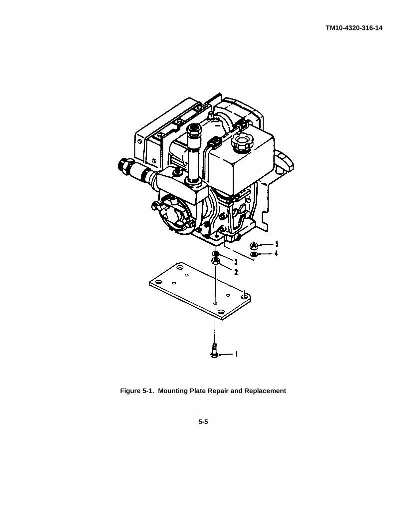
TM10-4320-316-14
Figure 5-1. Mounting Plate Repair and Replacement
5-5
TM10-4320-316-14
5-8. FUEL INJECTOR VALVE ASSEMBLY REPLACEMENT.
This Task Covers:
a. Removal b. Test c. Installation
Initial Setup:
Tools RequiredTool Kit, General Mechanic's (Appendix B, item 1)Test Stand, Injector (Appendix B, Item 3)Torque Wrench Common 0-175 in-lb (Appendix B, Item 3)
Material's RequiredCloth, Lint-free (Appendix E, Item 1)Hex Head Bolt, 3/8 x 4 inch UNC (Appendix B, Item 6)
Equipment ConditionDED pump assembly shut down and cool.Inlet enclosure removed (see paragraph 4-22).
a. Removal. (Refer to Figure 5-2).
CAUTION
Do not touch tip of fuel injection nozzle as damage to equipment can occur.
(1) Remove clamp (1) and fuel return line (2) from fuel injector valve assembly.
(2) Remove two hex head nuts (3), retaining plate (4), and the strap for the valve cover rubber plug.
NOTE
If the nozzle is tight, gently pry nozzle using a small pry bar. Be careful not to pryon the fuel return hose hub.
(3) Carefully remove fuel injection nozzle (5). Wrap it in clean cloth to protect the nozzle tip. Do notplace nozzle tip directly on any dirty surface without protection.
(4) If nozzle gasket (6) and spacer (7) are not attached to nozzle at removal, screw a 3/8 x 4 inch UNChex head bolt into nozzle gasket, then remove stud bolt. The gasket and spacer should come out and be discarded.
WARNING
Death or serious injury could occur if fuel is not handled properly. Use in a well-ventilated area away from open flame, arcing equipment, ignition sources,heaters, or excessive heat. Always store fuel in properly marked containers. DONOT SMOKE.
5-6

TM10-4320-316-14
Figure 5-2. Fuel Injector Valve Assembly Replacement.
b. Test.
(1) Use nozzle test to check injection starting pressure. Pressure should be 2,844 psig (200 kg/cm2) +142psig (10 kg/sq cm).
(2) Spray pattern should be equal.
(3) Pressurize injector nozzle to 2,030 psig (140 kg/sq cm) for 60 seconds and check for leaks.
(4) If injector nozzle fails either test, replace.
c. Installation.
(1) Install new fuel injection nozzle gasket (6) and spacer (7) onto fuel injection nozzle (5) beforeinstalling nozzle into cylinder block.
NOTE
Make sure nozzle and sleeve surface is clean. Carbon deposits will build up onnozzle in the form of flowers. Flowering lowers combustion performancesignificantly.
5-7
TM10-4320-316-14
5-8. FUEL INJECTOR VALVE ASSEMBLY REPLACEMENT. - Continued.
(2) Carefully insert the fuel injection nozzle (5) into the cylinder block. Care must be taken in order toavoid damage to nozzle gasket (6).
(3) Make sure fuel injection nozzle (5) positioning pin slides (8) into the positioning slot.
(4) Position the strap for the valve cover rubber plug and secure nozzle (5) to engine with two hex headnuts (3) and retaining plate (4). Torque to 72-94 in-lb (80-100 cm-kg).
(5) Install fuel return line (2) and clamp (1) to injector valve assembly.
5-8/(5-9 Blank)

TM10-4320-31 6-14
5-9. REGULATOR BRACKET ASSEMBLY REPAIR, ADJUSTMENT, AND REPLACEMENT.
This Task Covers:
a. Removal b. Inspection c. Repair d. Installation e. Adjustment
Initial Setup:
Tools RequiredTool Kit, General Mechanic's (Appendix B, Item 1)Tachometer (Appendix B, Item 3)
Material’s RequiredDiesel Fuel (Appendix E, Item 6)
Equipment ConditionDED pump assembly shut down and cool.Inlet enclosure removed (see paragraph 4-22).Control assembly removed (see paragraph 4-15).
a. Removal. (Refer to Figure 5-3).
(1) Remove mounting bolts (1 and 2).
(2) Remove regulator bracket (3) with regulator lever (4) and springs attached.
(3) Remove regulator spring (5) from the governor lever (6) and regulator lever (4).
(4) Remove return spring (7) from the governor lever (6) and regulator lever (4).
(5) Remove regulator coil spring (8).
(6) Remove regulator lever (4) from regulator bracket (3) by unscrewing lever locking knob (9) and locknut(10).
(7) Remove adjusting bolt (11) and nut (12).
(8) Remove wire (13), bolt (14), and nut (15).
b. Inspection.
(1) Clean all parts with diesel fuel.
(2) Inspect all components for damage or excessive wear. Replace any components damaged or worn.
c. Repair.
Repair is limited to replacement of defective parts.
5-10

TM10-4320-316-14
Figure 5-3. Regulator Bracket Assembly Repair and Replacement.
5-11
TM10-4320-316-14
5-9. REGULATOR BRACKET ASSEMBLY REPAIR, ADJUSTMENT, ANDREPLACEMENT. - Continued.
d. Installation.
(1) Install nut (15) and bolt (14).
(2) Install nut (12) and adjusting bolt (11).
(3) Install regulator coil spring (8).
(4) Attach return spring (5) to the governor lever (6) and to regulator lever (4).
(5) Attach regulator spring (4) to the second hole from the left on the governor lever (2) and connectspring to second hole from the left on regulator lever (3).
(6) Mount regulator lever (4) to regulator bracket (3) using the locking nut (9). Secure with self-locking nut(10).
(7) Mount regulator bracket assembly (3) with mounting bolts (2 and 1).
(8) Lubricate all moving parts with lubricating oil.
e. Adjustment.
CAUTION
Do not operate engine and pump if all water has been removed from pump.Pump will be seriously damaged if it is operated without water in the pump body.
(1) Check that engine RPM is 3,650.
(2) Loosen nut (15) and adjust bolt (14) until engine operates at 3,650 RPM.
(3) When engine RPM is correct, tighten nut (15) to hold adjusting bolt (14) into position and install newwire (13) to seal adjustment.
5-12/(5-13 Blank)

TM 10-4320-316-14
5-10. CYLINDER HEAD ASSEMBLY REPAIR AND REPLACEMENT.
This Task Covers:
a. Removal b. Inspection c. Repair d. Installation e. Adjustment
Initial Setup:
Tools RequiredTool Kit, General Mechanic's (Appendix B, item 1)Fitting Tool, Valve Stem Seal (Appendix B, Item 3)Torque Wrench (Appendix B, Item 3)Compressor, Air (Appendix B, Item 3)Caliper, Slide (Appendix B, Item 3)Micrometer (Appendix B, Item 3)
Material's RequiredAbrasive Cloth (Appendix E, Item 5)Diesel Fuel (Appendix E, Item 6)Lubricating Oil (Appendix E, Item 7)Equipment ConditionDED pump assembly shut down and cool.Inlet enclosure removed (See paragraph 4-22).
a. Removal. (Refer to Figure 5-4).
(1) Remove plunger (1), holder (2), two screws (3), cylinder head cover (4), and gasket (5).
(2) Remove two cap nuts (6) and washers (7) from cylinder head studs (8).
(3) Remove two cylinder head nuts (9) and cylinder head washers (10) from cylinder head studs (11).
(4) Remove cylinder head assembly (12) by lifting straight up off the four cylinder head studs (8 and 11).
(5) Remove and discard push rod O-ring (13) and cylinder head gasket (14).
CAUTION
Keep intake and exhaust push rods separate. Switching push rods may damageengine.
(6) Tag and remove push rods (15).
5-14

TM10-4320-316-14
Figure 5-4. Cylinder Head Removal.
5-15

TM10-4320-316-14
5-10. CYLINDER HEAD ASSEMBLY REPAIR AND REPLACEMENT. - Continued.
b. Disassembly. (Refer to Figure 5-5.)
(1) Remove rocker arm support bolt (1).
(2) Remove rocker arm support (2) with intake and exhaust valve rocker arms (3 and 4) attached.
(3) Remove valve stem caps (5).
WARNING
Serious injury can be caused by the sudden release of spring loaded parts.Use extreme caution when removing valve springs.
(4) Compress valve spring (6), and remove retainer keeper (7) and retainer (8) from top of valve spring(6).
(5) Remove valve spring (6).
(6) Remove valve spring washer (9).
(7) Remove valves (10 and 11) from cylinder head.
(8) Remove valve seals (12) from cylinder head and discard.
5-16
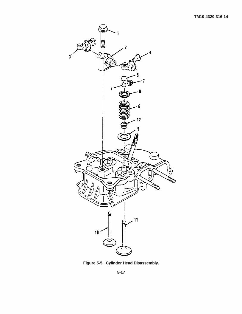
TM10-4320-316-14
Figure 5-5. Cylinder Head Disassembly.
5-17
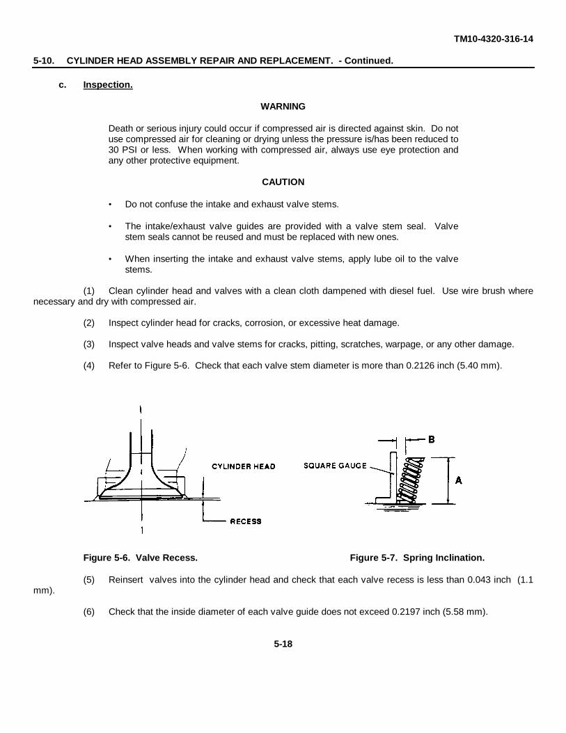
TM10-4320-316-14
5-10. CYLINDER HEAD ASSEMBLY REPAIR AND REPLACEMENT. - Continued.
c. Inspection.
WARNING
Death or serious injury could occur if compressed air is directed against skin. Do notuse compressed air for cleaning or drying unless the pressure is/has been reduced to30 PSI or less. When working with compressed air, always use eye protection andany other protective equipment.
CAUTION
• Do not confuse the intake and exhaust valve stems.
• The intake/exhaust valve guides are provided with a valve stem seal. Valvestem seals cannot be reused and must be replaced with new ones.
• When inserting the intake and exhaust valve stems, apply lube oil to the valvestems.
(1) Clean cylinder head and valves with a clean cloth dampened with diesel fuel. Use wire brush wherenecessary and dry with compressed air.
(2) Inspect cylinder head for cracks, corrosion, or excessive heat damage.
(3) Inspect valve heads and valve stems for cracks, pitting, scratches, warpage, or any other damage.
(4) Refer to Figure 5-6. Check that each valve stem diameter is more than 0.2126 inch (5.40 mm).
Figure 5-6. Valve Recess. Figure 5-7. Spring Inclination.
(5) Reinsert valves into the cylinder head and check that each valve recess is less than 0.043 inch (1.1mm).
(6) Check that the inside diameter of each valve guide does not exceed 0.2197 inch (5.58 mm).
5-18

TM10-4320-316-14
(7) Clean off carbon deposits on the valve seats since carbon buildup, excessive wear, and corrosion cancause compression leaks.
(8) Replace cylinder head if any of the following conditions exist:
If cylinder block contact surface is roughened or not level; if the valve seats are worn; if the valve rockerarm cover contact surface is rough or damaged; or if there a re cracks between the valve seats.
(9) Check the valve spring for flaw or corrosion.
(10) Refer to Figure 5-7. Check that the valve spring free length (dimension A) is more than 1.043 inches(26.5 mm).
(11) Check that the spring inclination (how far spring inclines to the left or right, dimension B) isless than 0.030 inch (0.75 mm).
(12) Check that the OD of the valve rocker arm support shaft Is more than 0.4685 inch (11.90 mm).
(13) Check that the ID of the valve rocker arm does not exceed 0 4764 inch (12.1 mm).
(14) Check for bending of the push rods.
(15) Inspect and clean thoroughly the gasket and O-ring areas of cylinder head and crankcase.
(16) Inspect studs (8) and (11). Replace if threads are stripped or broken.
d. Repair.
(1) Replace any components that do not meet inspection criteria.
(2) Remove slight scratches or scuff marks with crocus cloth.
e. Assembly. (Refer to Figure 5-5).
(1) Insert new valve stem seals onto valve guide.
(2) Insert valves (10 and 11) into cylinder head.
(3) Install valve spring washer (9).
(4) Install valve springs (6).
(5) Compress valve spring (6) and install retainer (8) and retainer keeper (7).
f. Installation.
(1) Refer to Figure 5-4. Place new cylinder head gasket (14) and push rod O-ring (13) onto cylinder block.
(2) Install cylinder head (12) onto four studs (8) and (11) protruding from cylinder block.
(3) Position push rods (15) into cylinder block in the cam followers.
5-19
TM10-4320-316-14
5-10. CYLINDER HEAD ASSEMBLY REPAIR AND REPLACEMENT. - Continued.
f. Installation. - Continued.
(4) Secure cylinder head (12) to cylinder block using two nuts (9), two washers (10), two nuts (6), and twowashers (7).
(5) Tighten nuts using torque wrench to 20-23 ft-lb (280-320 kg-cm).
(6) Refer to Figure 5-5. Install valve stem caps (5).
NOTE
Rocker arm with flat head is for the exhaust valve only.
(7) Install rocker arm support (2) with intake and exhaust valve rocker arms attached.
(8) Tighten rocker arm support bolt (1) with torque wrench to 14.5-16.6 ft-lb (200-230 kg-cm).
(9) Refer to Figure 5-4. Install gasket (5), cylinder head cover (4), two screws (3), holder (2), and plunger(1).
g. Adjustment. (Refer to Figure 5-8).
NOTE
Valve clearance should be adjusted when engine is cold.
(1) Turn flywheel so 'T" mark on flywheel aligns with alignment mark on cylinder block.
(2) Slightly rotate flywheel (approximately 20 degrees in both directions). If valves move up and down,this is the exhaust top dead center. Do not adjust the valve clearance with the flywheel in this position.
(3) Give flywheel another turn until '"T" mark on flywheel aligns with alignment mark on cylinder block.Slightly rotate flywheel (approximately 20 degrees in both directions). If valves do not move up and down, the flywheel isin correct position to check valve clearance.
(4) Check that 'T" mark and alignment mark are aligned correctly.
(5) Insert screwdriver into adjusting bolt and loosen locknut. Refer to Figure 5-9.
(6) Turn screwdriver counterclockwise to obtain a clearance. Move valve lever inside for adjustments.
(7) Insert feeler gauge between valve rocker arm and top of the valve spring cotter.
(8) While turning the adjusting screw clockwise, slowly slide the feeler gauge back and forth. Stop turningadjusting screw when slight resistance is felt on the feeler gauge.
(9) Remove feeler gauge and tighten locknut. Keep screwdriver inserted into adjusting screw to preventadjusting screw from turning.
(10) Verify valve clearance of 0.006 inch (0.15 mm) after completion.
5-20

TM10-4320-316-14
(11) Repeat on both intake and exhaust valves.
(12) After securing both locknuts, check that clearance is still 0.006 inch (0.15 mm).
Figure 5-8. Alignment of Flywheel With Cylinder Block.
Figure 5-9. Adjusting Valve Clearance.
5-21

TM 10-4320-316-14
5-11. FLYWHEEL REPLACEMENT.
This Task Covers:
a. Removal b. Installation
Initial Setup:
Tools RequiredTool Kit, General Mechanic's (Appendix B, item 1)Puller (Appendix B, Item 3)Torque Wrench (Appendix B, Item 3)
Material's RequiredNone
Equipment ConditionDED pump assembly shut down and cool.Cooling fan case removed (see paragraph 4-33).
a. Removal. (Refer to Figure 5-10).
(1) Remove starter pulley (1) by removing three bolts (2).
(2) Brace the flywheel (5) to prevent the flywheel from turning while loosening the flywheel nut (3) byinserting a pry bar through a hole in the flywheel into the depression in the crankcase.
(3) Remove flywheel end nut (3) and washer (4) from crankshaft (6).
(4) Using a puller, remove flywheel.
CAUTION
Be careful not to damage the taper part of the crankshaft.
(5) Remove flywheel key (7) from crankshaft (6)
b. Installation.
(1) Install flywheel key (7) onto crankshaft (6).
(2) Install flywheel (5) onto crankshaft (6).
(3) Install flywheel end nut (3) and washer (4).
(4) Tighten flywheel end nut (3) after bracing the flywheel by inserting a pry bar through a hole in theflywheel into the depression in the crankcase. Torque flywheel end nut to 73-80 ft-lb (1000-1100 cm-kg).
(5) Install starter pulley (1) and three bolts (2).
5-22
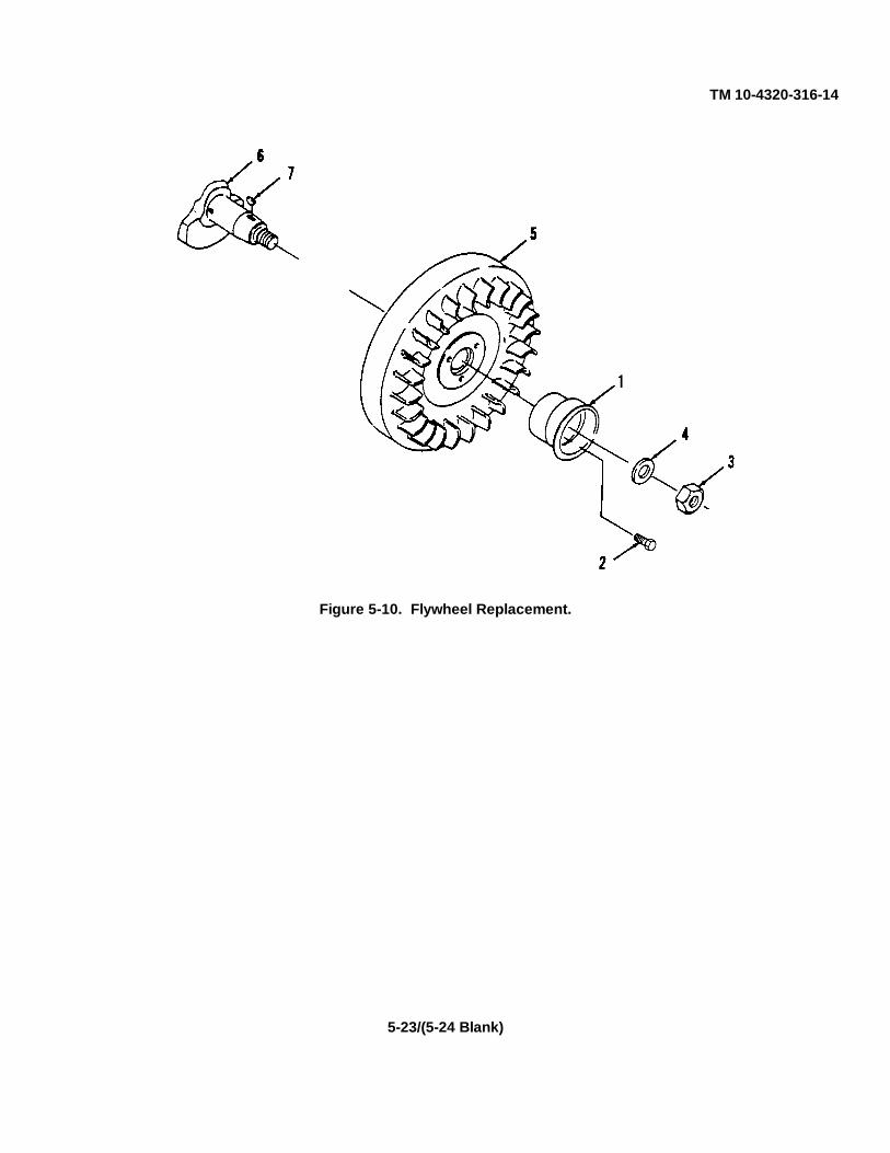
TM 10-4320-316-14
Figure 5-10. Flywheel Replacement.
5-23/(5-24 Blank)

TM10-4320-316-14
CHAPTER 6
GENERAL SUPPORT MAINTENANCE INSTRUCTIONS
SECTION I. GENERAL SUPPORT REPAIR PARTS, SPECIAL TOOLS, TESTMEASUREMENT AND DIAGNOSTIC EQUIPMENT (TMDE),AND SUPPORT EQUIPMENT
6-1. COMMON TOOLS AND EQUIPMENT. For authorized common tools and equipment, refer to the Modified Table ofOrganization and Equipment (MTOE) applicable to your unit.
6-2. SPECIAL TOOLS, TMDE, AND SUPPORT EQUIPMENT. The special tools required to service the centrifugalpump are listed and illustrated in TM10-4320-316-24P, Repair Pars and Special Tools List (RPSTL), and in theMaintenance Allocation Chart (MAC) located in Appendix B of this manual.
6-3. REPAIR PARTS. Repair parts are listed and illustrated in TM10-4320-316-24P.
SECTION II. GENERAL SUPPORT MAINTENANCE PROCEDURES
6-4. GENERAL SUPPORT MAINTENANCE PROCEDURES. Maintenance procedures at general support maintenancelevel include as necessary: removal, cleaning and inspection, repair or replacement, and installation. Unless theprocedure requires special resources or tools, more than one maintenance person or specific equipment conditions,these are not listed for each maintenance procedure. They are listed only for those procedures that require them.
6-1

TM 10-4320-316-146-5. CRANKCASE ASSEMBLY REPAIR AND REPLACEMENT.
This Task Covers:
a. Removal b. Inspection c. Repair d. Installation
Initial Setup:
Tools RequiredTool Kit, General Mechanic's (Appendix B, item 1)Caliper, Slide (Appendix B, Item 3)Bearing Puller (Appendix B, Item 3)Torque, Wrench (Appendix B, Item 3)
Material's RequiredLubricating Oil (Appendix E, Item 8)Diesel Fuel (Appendix E, Item 6)Oil Seal Gasket, 114250-01412
Equipment ConditionDED pump assembly shut down and cool.Bottom pan frame removed (see paragraph 4-25).
a. Removal. (Refer to Figure 6-1).
CAUTION
Oil pump cover and oil filter cover do not have to be disassembled to remove crankcasecover and should only be disassembled when necessary.
(1) Remove fourteen crankcase cover bolts (1).
(2) Remove one additional crankcase cover bolt (2) located inside of the bolt pattern and above the lube oilstrainer.
(3) Remove crankcase cover (3) and discard gasket (4).
(4) Remove and discard oil seal (5).
(5) Remove lube oil inlet pipe (6) from crankcase cover (3).
b. Inspection.
(1) Clean out each oil hole on the crankcase cover with diesel fuel. Insure oil passages are not clogged.
(2) Check the main bearing metal insert on the crankcase side for discoloration or damage.
6-2

TM 10-4320-316-14
Figure 6-1. Crankcase Cover Replacement.
6-3

TM10-4320-316-146-5. CRANKCASE ASSEMBLY REPAIR AND REPLACEMENT. - Continued.
c. Repair.
(1) Replace the main bearing metal insert if it is discolored or damaged.
(a) Remove bad main bearing metal insert (1).
(b) Insert main bearing (1) into crankcase cover (2). Carefully fit the main bearing so that the oil groove isin the upper half and the oil hole in the bearing is aligned with the oil groove.
(c) Press fit the main bearing until recess is 0.0039 inch (1 mm) past the cover edge.
Figure 6-2. Main Bearing Insert Removal.
(2) Replace the camshaft ball bearing or the balance shaft ball bearing.
(a) Remove bad bearing (3) using a mechanical bearing puller.
(b) Press fit the new ball bearing (3) into the crankcase cover (2).
(3) Refer to Figure 6-2. Replace crankshaft oil seal.
(a) Insert new crankshaft oil seal (5) into crankcase cover (3).
(b) Insert crankshaft seal into crankcase cover until it is 0.1575 inch (4 mm) deep from the end ofcrankcase.
(4) Replace crankcase cover gasket (4).
6-4

TM10-4320-316-14
b. Installation. (Refer to Figure 6-1).
(1) Install lube oil inlet pipe (6) into crankcase cover (3).
(2) Place a crankcase cover gasket (4) between the surface of the crankcase and the crankcase cover (3).
(3) Apply oil to the lips of oil seal (5).
(4) Apply lubricating oil to crankshaft and camshaft.
(5) Make sure that the oil pump drive gears are properly engaged.
(6) Carefully guide the crankcase cover (3) over the crankshaft and insure that the seal seats properly.
(7) Attach crankcase cover (3) to the cylinder block using 14 bolts (1) plus additional bolt (2) located above thelube oil strainer.
(8) Refer to Figure 6-3. Tighten bolts in sequence shown and torque to 72-96 in-lb (83-110 kg-cm).
Figure 6-3. Tightening Sequence for Crankcase Cover Bolts.
6-5
TM10-4320-316-146-6. PISTON AND CONNECTING ROD ASSEMBLY REPAIR AND REPLACEMENT.
This Task Covers:
a. Removal b. Inspection c. Repair d. Installation
Initial Setup:
Tools RequiredTool Kit, General Mechanic's (Appendix B, item 1)Snap Ring Pliers (Appendix B, Item 3)Piston Ring Expander (Appendix B, Item 4)Piston Ring Groove Cleaner (Appendix B, Item 4)Piston Ring Compressor (Appendix B, Item 4)Torque Wrench (Appendix B, Item 3)Gloves (Appendix B, Item 3)
Materials RequiredDiesel Fuel (Appendix E, Item 6)Lubricating Oil (Appendix E, Item 8)Plastigage, PG-1 (Appendix E, Item 9)
Equipment ConditionDED pump assembly shut down and cool.Camshaft removed (see paragraph 6-9)Balancer shaft removed (see paragraph 6-8)
a. Removal. (Refer to Figure 6-4).
(1) Remove carbon deposited on the upper inside surface of the cylinder before extracting the piston.
(2) Remove two connecting rod mounting bolts (1), nuts (2), and washers (3).
(3) Remove connecting rod cap (4).
(4) Rotate crankshaft to the top of the piston stroke and pull out piston (5).
(5) Remove both snap lock rings (6).
WARNING
Heated parts can result in severe burns Exercise care in handling the heated parts.
CAUTION
Avoid heating piston directly with a torch.
(6) Heat piston (5) and piston pin (7) to 160-180°F.
(7) Remove piston pin (7) from piston (5).
(8) Connecting rod (8) can now be separated from piston.
6-6

TM10-4320-316-14
Figure 6-4. Piston and Connecting Rod Assembly Replacement.
6-7
TM10-4320-316-146-6. PISTON AND CONNECTING ROD ASSEMBLY REPAIR AND REPLACEMENT. - Continued.
a. Removal. - Continued.
CAUTION
Piston ring breakage may occur if rings are opened more than necessary when removing.Never stretch piston rings more than necessary.
(9) Use the piston ring remover tool to remove piston rings (9), (10), and (11). Discard piston rings.
NOTE
Prior to inspecting/evaluating the piston and connecting rod assembly, evaluate the cylinder. Check thatthe cylinder ID is no greater than 2.684 inches (68.16 mm). If the cylinder sleeve is greater than this wearlimit, follow the procedures to replace the crankcase.
b. Inspection.
(1) Clean piston (5) and piston pin (7).
(2) Remove carbon from piston and piston components.
(3) Carefully clean the piston ring groove after the piston rings have been removed.
(4) Inspect piston, piston skirt, piston grooves, and piston pin for excessive wear, discoloration, and damage.Replace damaged piston.
NOTE
Before reading any measurements, all carbon buildup must be removed. Carbon buildup will causeunreliable measurements.
(5) Check that the OD of piston is greater than 2.665 inches (67.68 mm). Measure piston OD 90 degrees fromthe piston pin hole and about 0.50 inch (12 mm) from the bottom of piston. Replace piston if worn beyond the wear limit.
(6) Check that the ID of the piston pin hole is less than 0.751 inch (19.07 mm). Replace piston if ID exceeds wearlimit.
(7) Check that the OD of the piston pin is greater than 0.745 inch (18.92 mm). Replace piston pin if OD is wornbeyond the wear limit.
(8) Clean connecting rod components with diesel fuel.
(9) Inspect all connecting rod components for bending, warping, cracking, excessive wear, or any other damage.Replace any components damaged or worn.
(10) Check that piston pin hole ID (small end hole) of connecting rod is less than 0.752 inch (19.1 mm). Replaceconnecting rod if piston pin hole diameter exceeds wear limit.
(11) Check that crank pin hole ID (large end hole) of connecting rod is less than 1.184 inches (30.08 mm).Replace connecting rod if crank pin hole diameter exceeds wear limit
6-8
TM10-4320-316-14
(12) Check the thrust surface on both ends of the connecting rod for damage. Replace connecting rod ifnecessary.
(13) Check the contact surface of the crank pin bearing insert for separation, melting, seizure, etc. Replace crankpin bearing insert if it is separated or damaged.
(14) Check that clearance between crank pin and crank pin bearing insert is less than 0.004 inch (0.12 mm).Replace crankpin bearing insert if clearance exceeds wear limit.
c. Repair. Repair is limited to replacement of defective parts.
d. Installation.
WARNING
Heated parts can result in severe burns. Exercise care in handling the heated parts.
CAUTION
Connecting rod is made of a special aluminum alloy. Avoid damage while handling. Do not dropor clash against a hard object.
CAUTION
Avoid direct heating of piston with a torch.
(1) Heat piston (5) to 160-180'F.
(2) Position the piston top identification mark "DM" (12) and the ID number on the connecting rod as shown.
(3) Align the small end hole of connecting rod (8) with the piston.
(4) Insert piston pin (7) into the piston pin hole.
(5) Insert two snap lock rings (6) into piston pin holes.
NOTE
Any time piston is removed from engine, new piston rings should be installed.
(6) Measure piston ring end gap of each piston ring.
(7) When inserting the rings, the identification mark should face up.
CAUTION
Piston ring breakage may occur if rings are opened more than necessary when installing.Never stretch piston rings more than necessary.
NOTE
The top piston ring will have a 'T" on the top surface. The middle piston ring will havea "2T' on the top surface and the bottom piston ring will have a "1" on the top surface.
(8) Use the piston ring remover tool to install piston rings (9), (10), and (11). Install oil ring, 2nd compression ring,and 1st compression ring in order.
6-9

TM10-4320-316-146-6. PISTON AND CONNECTING ROD ASSEMBLY REPAIR AND REPLACEMENT. - Continued.
d. Installation. - Continued.
(9) Make sure each piston ring gap is 120 degrees.
(10) Make sure the piston rings move smoothly.
NOTE
Cylinder walls should have a deglazed and cross-hatched pattern. The surface should be clean and dry.
(11) Apply liberal amount of lubricating oil to the outer surface of the piston and inner surface of the cylinder.
(12) Align the identification mark DM on the piston head with the mark on the crankcase.
(13) Install new connecting rod bearing insert (14) into connecting rod (8).
(14) Apply oil to the crank pin on the crankshaft.
CAUTION
Connecting rod is made of a special aluminum alloy. Avoid damage while handling. Do not dropor clash against a hard object.
(15) Insert the piston and connecting rod assembly into the cylinder using a piston ring compressor, and move thecrankshaft to top dead center. The identification mark DM on the piston head should align with the mark on the cylinderblock.
(16) Insert connecting rod end cap bearing insert (14) into connecting rod end cap (4).
(17) Install the connecting rod cap (4) using bolts (1), washers (3), and nuts (2). Rotate flywheel so piston is atbottom dead center. Tightening torque for connecting rod bolts is 13.0-14.5 ft-lb (190-200 cm-kg).
6-10/(6-11 Blank)
TM10-4320-316-146-7. GOVERNOR ASSEMBLY AND LUBE OIL PUMP REPAIR AND REPLACEMENT.
This Task Covers:
a. Removal b. Inspection c. Repair d. Installation
Initial Setup:
Tools RequiredTool Kit, General Mechanic's (Appendix B, item 1)
Materials RequiredDiesel Fuel (Appendix E, Item 6)
Equipment ConditionDED pump assembly shut down and cool.Crankshaft removed (see paragraph 6-10).
a. Removal.
(1) Governor Assembly Removal. (Refer to Figure 6-5).
(a) Remove governor lever taper pin (1).
(b) Remove governor lever (2).
(c) Remove governor control arm (3) and governor shaft (4) from inside the engine.
(d) Remove governor control arm lever taper pin (5).
(e) Remove governor control arm (3) from the governor shaft (4).
(f) Remove thrust bushing (6).
(g) Remove needle bearing (7) and washer (8).
(h) Remove nut (9) from fuel limiting adjustment (10).
(i) Remove fuel limiting adjustment (10) from crankcase.
(2) Lube Oil Pump Removal. (Refer to Figure 6-6).
(a) Remove three lube oil pump cover bolts (1) holding lube oil pump cover (2).
(b) Remove lube oil pump cover (2) and O-ring (3). Discard O-ring.
(c) Lay crankcase cover on clean, flat surface.
(d) Grasp hold of the plastic gear (4) and carefully pull spindle (5) from lube oil pump shaft.
(e) Remove drive pin (6).
(f) Remove lube oil pump shaft (7) and outer rotor (8) from crankcase cover.
6-12
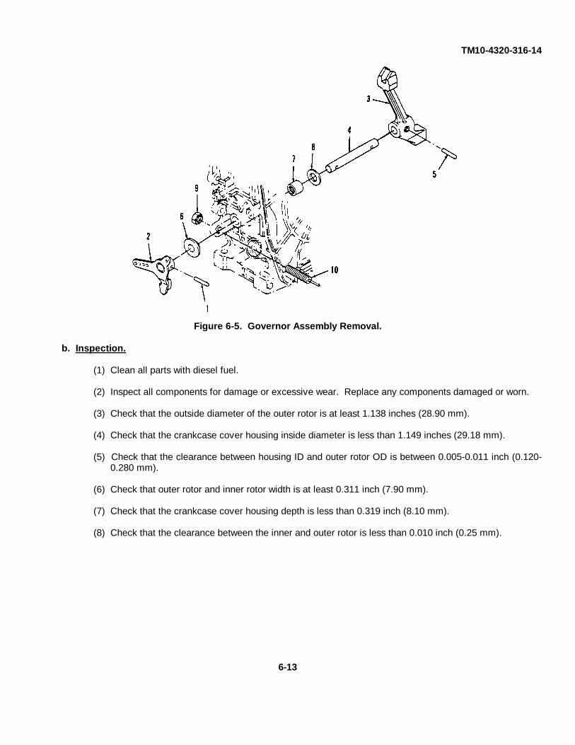
TM10-4320-316-14
Figure 6-5. Governor Assembly Removal.
b. Inspection.
(1) Clean all parts with diesel fuel.
(2) Inspect all components for damage or excessive wear. Replace any components damaged or worn.
(3) Check that the outside diameter of the outer rotor is at least 1.138 inches (28.90 mm).
(4) Check that the crankcase cover housing inside diameter is less than 1.149 inches (29.18 mm).
(5) Check that the clearance between housing ID and outer rotor OD is between 0.005-0.011 inch (0.120-0.280 mm).
(6) Check that outer rotor and inner rotor width is at least 0.311 inch (7.90 mm).
(7) Check that the crankcase cover housing depth is less than 0.319 inch (8.10 mm).
(8) Check that the clearance between the inner and outer rotor is less than 0.010 inch (0.25 mm).
6-13

TM10-4320-316-14
6-7. GOVERNOR ASSEMBLY AND LUBE OIL PUMP REPAIR AND REPLACEMENT. - Continued.
Figure 6-6. Lube Oil Pump Repair and Replacement.
Figure 6-7. Lube Oil Pump Installation.
6-14

TM10-4320-316-14
c. Repair. Repair is limited to the replacement of defective parts as described in the following steps.
(1) Replace lube oil pump if the OD of the outer rotor is less than 1.138 inches (28.9 mm).
(2) Replace crankcase cover if the housing ID is greater than 1.149 inches (29.18 mm).
(3) Replace the lube oil pump if the clearance between housing ID and outer rotor OD is greater than 0.011 inch(0.280 mm).
(4) Replace lube oil pump if the outer and inner rotor width is less than 0.311 inch (7.9 mm).
(5) Replace crankcase cover if the housing depth is greater than 0.319 inch (8.1 mm).
(6) Replace lube oil pump if the clearance between the inner and outer rotor is less than 0.010 inch (0.25 mm).
d. Installation.
(1) Lube Oil Pump.
(a) (Refer to Figure 6-7). Insert lubricating oil pump assembly (1) from the outside of the crankcase cover(2). Coat the rotor with oil before installing the cover.
(b) Insert drive pin (3) into the lubricating oil pump shaft (4).
(c) Insert spindle (5) into the weights (6) on the governor gear assembly (7), then push the governor gearassembly (7) onto the oil pump shaft (4). Ensure that gear is firmly engaged onto pin (3). (d) (Refer to Figure 6-6).Install new O-ring (3) onto crankcase cover and secure oil pump cover (2) with 3 bolts (1).
(2) Governor Assembly. (Refer to Figure 6-5).
(a) Install fuel limiting adjustment (10) into crankcase.
(b) Install nut (9) onto fuel limiting adjustment (10).
(c) Install needle bearing (7) into cylinder block.
(d) Insert shaft (4) into governor control arm (3) and lock into position with taper pin (5).
(e) Install governor control arm (3), shaft (4), and washer (8) into needle bearing in engine from the inside.
(f) Insert thrust bushing (6) onto shaft (4) in cylinder block.
(g) Install control arm lever (2) onto shaft (4) and insert taper pin (1) into shaft.
(h) After engine has been reassembled, adjust engine speed control device per paragraph 5-9.
6-15

TM 10-4320-316-146-8. BALANCER SHAFT ASSEMBLY REPLACEMENT.
This Task Covers:
a. Removal b. Installation
Initial Setup:
Tools RequiredTool Kit, General Mechanic's (Appendix B, item 1)
Materials RequiredDiesel Fuel (Appendix E, Item 6)
Equipment ConditionDED pump assembly shut down and cool.Crankcase cover removed (see paragraph 6-5).
a. Removal. (Refer to Figure 6-8).
(1) Check the location of the timing marks on all gears.
(2) Remove the balancer shaft (1).
b. Installation.
(1) Insert the balancer shaft assembly (1) into the cylinder block (2).
(2) Refer to Figure 6-9. Make sure the timing marks (1) on the balancer gear (2) and the crank gear (3)are aligned.
6-16
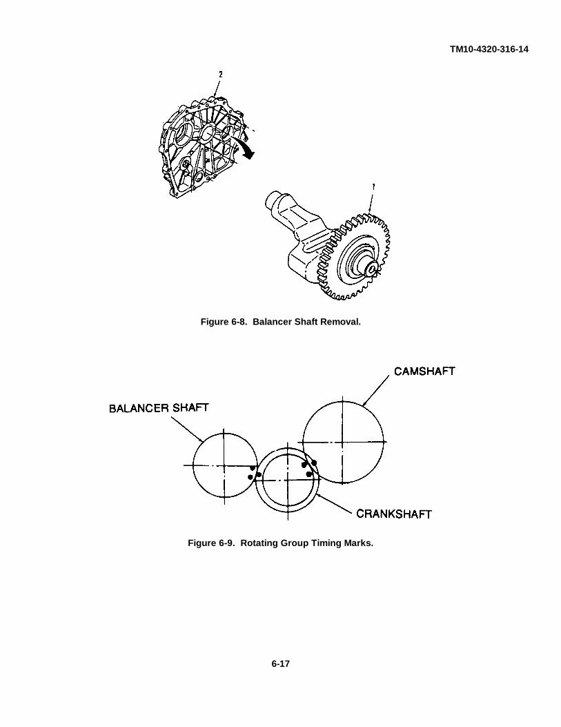
TM10-4320-316-14
Figure 6-8. Balancer Shaft Removal.
Figure 6-9. Rotating Group Timing Marks.
6-17
TM10-4320-316-146-9. CAMSHAFT ASSEMBLY REPLACEMENT.
This Task Covers:
a. Removal b. Installation
Initial Setup:
Tools RequiredTool Kit, General Mechanic's (Appendix B, item 1)Micrometer Set (Appendix B, Item 3)Arbor Press (Appendix B, Item 3)
Materials RequiredDiesel Fuel (Appendix E, Item 6)
Equipment ConditionDED pump assembly shut down and cool.Fuel injection pump removed. (see paragraph 4-34).Cylinder head and valve assembly removed (see paragraph 5-10).Crankcase cover removed (see paragraph 6-5).
a. Removal (Refer to Figure 6-10).
CAUTION
Keep exhaust and intake tappets separate. They may fall down when pulling out thecamshaft and may be confused.
(1) Check the location of the timing marks on all gears.
(2) Lay engine down on the flywheel side to prevent tappets from falling out
(3) Pull out the camshaft (1) from engine (2).
b. Installation.
CAUTION
Keep the intake and exhaust tappets separate and return into same location atreassembly.
(1) Insert the intake and exhaust valve tappets into the cylinder block.
(2) Insert the camshaft assembly (1) into the cylinder block.
(3) Refer to Figure 6-11. Align timing marks on the cam gear (1) and crank gear (2).
6-18

TM10-4320-316-14
Figure 6-10. Camshaft Removal.
Figure 6-11. Camshaft Timing Marks.
6-19

TM10-4320-316-146-10. CRANKSHAFT REPLACEMENT.
This Task Covers:
a. Removal b. Installation
Initial Setup:
Tools RequiredTool Kit, General Mechanic's (Appendix B, item 1)
Materials RequiredDiesel Fuel (Appendix E, Item 6)Lubricating Oil (Appendix E, Item 8)Oil Seal, 160110-02220
Equipment ConditionDED pump assembly shut down and cool.Piston and connecting rod assembly removed (see paragraph 6-6).Flywheel removed (see paragraph 5-11).
a. Removal. (Refer to Figure 6-12).
(1) Remove bearing holder (1) and bearing holder nut (2).
(2) Pull out the crankshaft (3). It may be necessary to carefully tap crankshaft with a rubber mallet.
(3) Remove oil seal (4) and discard.
b. Installation.
(1) Lubricate the new oil seal lips and install into crankcase.
CAUTION
Crankshaft must be carefully installed into crankcase to avoid damaging the crankcaseoil seal.
(2) Install the crankshaft (3) into the crankcase.
(3) Make sure crankshaft has been inserted as far as it will go by tapping on crankshaft with rubber mallet.
(4) Install the bearing holder (1). Secure with bolt (2).
6-20

TM10-4320-316-14
Figure 6-12. Crankshaft Replacement.
6-21/(6-22 Blank)

TM10-4320-316-14
APPENDIX A
REFERENCES
A-1. SCOPE. This appendix lists all forms, field manuals, technical manuals, and miscellaneous publicationsreferenced in this manual.
A-2. FORMS.Report of Discrepancy .......................................................................................................................SF 364Equipment Inspection and Maintenance Worksheet .............................................................. DA Form 2404Product Quality Deficiency Report .....................................................................................................SF 368Recommended Changes to Equipment TechnicalPublications ...............................................................................................................DA Form 2028-2Recommended Changes to Publications and Blank Forms ................................................... DA Form 2028
A-3. FIELD MANUALS.First Aid For Soldiers ....................................................................................................................FM 21-11NBC Contamination Avoidance .........................................................................................................FM 3-3NBC Protection ...............................................................................................................................FM 34NBC Decontamination ......................................................................................................................FM 3-5Petroleum Supply Point Equipment and Operation .......................................................................FM 10-69
A-4. TECHNICAL MANUALS.Administrative Storage of Equipment .......................................................................................TM 740-90-1Procedures for Destruction of Equipment to PreventEnemy Use (Mobility Equipment Command) ..........................................................................TM 750-244-3Unit, Direct Support, and General Support Repair Parts andSpecial Tools List for Pumping Assembly, 65 GPM .....................................................TM10-4320-316-24P
A-5. MISCELLANEOUS PUBLICATIONS AND STANDARDS.The Army Maintenance Management System ...................................................................DA PAM 738-750Abbreviations for Use on Drawings, And Standards, Specificationsand Technical Documents .........................................................................................................MIL-STD-12Army Medical Department Expendable/Durable Items . ...............................................................CTA 8-100Expendable Items (Except Medical Class V, Repair Partsand Heraldic Items) .................................................................................................................. CTA 50-970Lubrication Order ............................................................................................................LO10-4320-316-12
A-1/(A-2 Blank)

TM10-4320-316-14
APPENDIX B
MAINTENANCE ALLOCATION CHART
SECTION I. INTRODUCTION
B-1. The Army Maintenance System MAC.
a. This introduction (section I) provides a general explanation of all maintenance and repair functions authorized atvarious maintenance categories under the standard Army Maintenance System concept.
b. The Maintenance Allocation Chart (MAC) in section II designates overall authority and responsibility for theperformance of maintenance functions on the identified end item or component. The application of the maintenancefunctions to the end item or component will be consistent with the capacities and capabilities of the designatedmaintenance levels which are shown on the MAC in column (4) as:
Unit - includes two subcolumns, C (operator/crew) and O (unit Maintenance).
Direct Support - includes and F subcolumn.
General Support - includes an H subcolumn.
Depot - includes a D subcolumn.
c. Section III lists the tools and test equipment (both special tools and common tool sets) required for eachmaintenance function as referenced from section II.
d. Section [V contains supplemental instructions and explanatory notes for a particular maintenance function.
B-2. Maintenance Functions. Maintenance functions are limited to and defined as follows:
a. Inspect. To determine the serviceability of an item by comparing its physical, mechanical, and/or electricalcharacteristics with established standards through examination (e.g., by sight, sound, or feel).
b. Test. To verify serviceability by measuring the mechanical, pneumatic, hydraulic, or electrical characteristicsof an item and comparing those characteristics with prescribed standards.
c. Service. Operations required periodically to keep an item in proper operating condition, e.g., to clean (includesdecontaminate, when required), to preserve, to drain, to paint, or to replenish fuel, lubricants, chemical fluids, or gases.
d. Adjust. To maintain or regulate, within prescribed limits, by bringing into proper or exact position, or by settingthe operating characteristics to specified parameters.
e. Align To adjust specified variable elements of an item to bring about optimum or desired performance.
B-1

TM10-4320-316-14
f. Calibrate. To determine and cause corrections to be made or to be adjusted on instruments or test, measuring,and diagnostic equipments used in precision measurement. Consists of comparisons of two instruments, one of which isa certified standard of known accuracy, to detect and adjust any discrepancy in the accuracy of the instrument beingcompared.
g. Remove / Install. To remove and install the same item when required to perform service or other maintenancefunctions. Install may be the act of emplacing, seating, or fixing into position a spare, repair part, or module (componentor assembly) in a manner to allow the proper functioning of an equipment or system.
h. Replace. To remove an unserviceable item and install a serviceable counterpart in its place. "Replace" isauthorized by the MAC and assigned maintenance level is shown as the 3rd position code of the SMR code.
i. Repair. The application of maintenance services1, including fault location/trouble-shooting2,removal/installation, and disassembly/assembly3 procedures, and maintenance actions4 to identify troubles and restoreserviceability to an item by correcting specific damage, fault, malfunction, or failure in a part, subassembly, module(component or assembly), end item, or system.
j. Overhaul. That maintenance effort (service/action) prescribed to restore an item to a completelyserviceable/operational condition as required by maintenance standards in appropriate technical publications (i.e.,DMWR). Overhaul is normally the highest degree of maintenance performed by the Army. Overhaul does not normallyreturn an item to like new condition.
k. Rebuild. Consists of those services/actions necessary for the restoration of unserviceable equipment to a likenew condition in accordance with original manufacturing standards. Rebuild is the highest degree of materialmaintenance applied to Army equipment. The rebuild operation includes the act of returning to zero those agemeasurements (hours/miles, etc.) considered in classifying Army equipment/components.
1Services - Inspect, test, service, adjust, align, calibrate, and/or replace.2Fault location l/troubleshooting - The process of investigating and detecting the cause of equipment
malfunctioning; the act of isolating a fault within a system or unit under test (UUT).3Disassembly / assembly - The step-by-step breakdown (taking apart) of a spare/functional group coded
item to the level of its least component, that is assigned an SMR code for the level of maintenance underconsideration (i. e., identified as maintenance significant).
4Actions - Welding, grinding, riveting, straightening, facing, machining, and or resurfacing.
B-2
TM10-4320-316-14
B-3. Explanation of Columns In the MAC, SECTION II.
a. Column 1, Group Number. Column 1 lists functional group code numbers, the purpose of which is to identifymaintenance significant components, assemblies, subassemblies, and modules with the next higher assembly.
b. Column 2. Component/Assembly. Column 2 contains the names of components, assemblies,subassemblies, and modules for which maintenance is authorized.
c. Column 3, Maintenance Function. Column 3 lists the functions to be performed on the item listed in Column2. (For detailed explanation of these functions, see paragraph B-2.)
d. Column 4, Maintenance Level. Column 4 specifies each level of maintenance authorized to perform eachfunction listed in Column 3, by indicating work time required (expressed as man hours in whole hours or decimals)in theappropriate subcolumn. This work-time figure represents the active time required to perform that maintenance functionat the indicated level of maintenance. If the number or complexity of the tasks within the listed maintenance functionvary at different maintenance levels, appropriate work-time figures are to be shown for each level. The work-time figurerepresents the average time required to restore an item (assembly, subassembly, component, module, end item, orsystem) to a serviceable condition under typical field operating conditions. This time includes preparation time (includingany necessary disassembly/assembly time), troubleshooting/fault location time, and quality assurance/quality control timein addition to the time required to perform the specific tasks identified for the maintenance functions authorized in themaintenance allocation chart. The symbol designations for the various maintenance levels are as follows:
C ............... Operator or crew maintenanceO ...............Unit maintenanceF ...............Direct support maintenanceL ...............Specialized Repair Activity (SRA)H ...............General support maintenanceD ...............Depot maintenance
e. Column 5, Tools and Test Equipment reference code. Column 5 specifies, by code, those common toolssets (not individual tools), common TMDE, and special tools, special TMDE, and support equipment required to performthe designated function. Codes are keyed to tools and test equipment in section III.
f. Column 6. Remarks. When applicable, this column contains a letter code, in alphabetical order, which iskeyed to the remarks contained in Section IV.
B-4. Explanation of Columns In Tools and Test Equipment Requirements, Section III.
a. Column 1, Reference Code. The tool and test equipment reference code correlates with a code used in theMAC, Section II, Column 5.
b. Column 2, Maintenance Level. The lowest level of maintenance authorized to use the tool or test equipment.
c. Column 3, Nomenclature. Name or identification of the tool or test equipment.
d. Column 4, National Stock Number. The National stock number of the tool or test equipment.
B-3

TM10-4320-316-14e. Column 5, Tool Number. The manufacturer's part number, model number, or type number.
B-5. Explanation of Columns In Remarks, Section IV.
a. Column 1. Reference Code. The code recorded in column 6, Section II.
b. Column 2, Remarks. This column lists information pertinent to the maintenance function being performed asindicated in the MAC, Section II.
B-4

TM10-4320-316-14
SECTION II. MAINTENANCE ALLOCATION CHARTFOR
PUMP UNIT, CENTRIFUGAL, DIESEL-DRIVEN.
00 PUMP UNITCENTRIFUGALDIESEL-DRIVEN
01 ENCLOSUREASSEMBLY
0101 Compression Inspect 0.1Release Handle Replace 0.3 1
0102 Control Inspect 0.1Assembly Replace 0.3 1
0103 Air Intake Hose Inspect 0.1Replace 0.3 1
0104 Exhaust Inspect 0.1Extension Replace 0.3 1
0105 Access Cover Inspect 0.1Repair 0.2 1 AReplace 0.2 1
0106 Pump Drain Inspect 0.1Repair 0.2 1 AReplace 0.2 1
0107 Oil Drain Inspect 0.1Repair 0.2 1 AReplace 0.2 1
0108 Baffles Inspect 0.2Replace 0.2 1
0109 Enclosure Inspect 0.3Assembly, Repair 0.6 1, 4 AInlet Side Replace 0.4 1
0110 Enclosure Inspect 0.3Assembly, Repair 0.6 1, 4 AOutlet Side Replace 0.4 1
TOOLSAND
EQUIP
MAINTENANCEFUNCTION
REMARKS
COMPONENTASSEMBLY
GROUPNUMBER
C O F H D
MAINTENANCE LEVEL
B-5

TM10-4320-316-14
SECTION II. MAINTENANCE ALLOCATION CHARTFOR
PUMP UNIT, CENTRIFUGAL, DIESEL-DRIVEN.
0305 Pipe Fuel Inspect 0.1Gauge Replace 0.3 1
0306 Fuel Lines Inspect 0.1Replace 0.5 1
0307 Air Cleaner Inspect 0.1Repair 0.4 1 AReplace 0.5 1
030701 Filter Element Inspect 0.1Service 0.2Replace 0.2
030702 Air Intake Pipe Inspect 0.1Repair 0.2 1 AReplace 0.3 1
0308 Exhaust Silencer Inspect 0.1Repair 0.3 1 AReplace 0.4 1
0309 Recoil Starter Inspect 0.2Repair 0.5 1, 2 AReplace 0.4 1, 2
0310 Cooling Fan Inspect 0.1Case Replace 0.4 1, 2
0311 Fuel Injector Test 0.5 1, 3Valve Assembly Replace 0.6 1, 3, 5 B
0312 Fuel Injector Inspect 0.1Pump Replace 0.5 1, 3
0313 Lube Oil Inspect 0.1Strainer Service 0.2
Repair 0.2 AReplace 0.2
TOOLSAND
EQUIP
MAINTENANCEFUNCTION
REMARKS
COMPONENTASSEMBLY
GROUPNUMBER
C O F H D
MAINTENANCE LEVEL
B-7

TM10-4320-316-14
SECTION II. MAINTENANCE ALLOCATION CHARTFOR
PUMP UNIT, CENTRIFUGAL, DIESEL-DRIVEN.
0314 Oil Cap/Gauge Inspect 0.1Repair 0.2 AReplace 0.1
0315 Regulator Inspect 0.3 0.2Bracket Repair 0.4 1 AAssembly Replace 0.4 1
Adjust 0.2
0316 Cylinder Head Inspect 0.2 1, 3Assembly Repair 1.5 1, 3
Replace 1.0 1, 3Adjust 1.0 1, 3
0317 Flywheel Inspect 0.1 1Replace 0.4 1
0318 Crankcase Inspect 0.2Assembly Repair 0.3 1, 3 A
Replace 0.3 1, 3
0319 Piston and Inspect 0.2 1, 3Connecting Rod Repair 1.0 1, 3 AAssembly Replace 1.0 1, 3
0320 Governor Inspect 0.2 1, 3Assembly Repair 0.3 1, 3 A
Replace 0.3 1, 3
0321 Lube Oil Pump Inspect 0.2Repair 0.3 1 AReplace 0.3 1
0322 Balancer Shaft Inspect 0.2 1, 3Assembly Replace 0.4 1, 3
0323 Camshaft Inspect 0.3 1, 3Assembly Replace 0.5 1, 3
0324 Crankshaft Inspect 0.3 1, 3Assembly Replace 0.5 1, 3
0325 Cylinder Block Replace 0.3 1, 3
TOOLSAND
EQUIP
MAINTENANCEFUNCTION
REMARKS
COMPONENTASSEMBLY
GROUPNUMBER
C O F H D
MAINTENANCE LEVEL
B-8
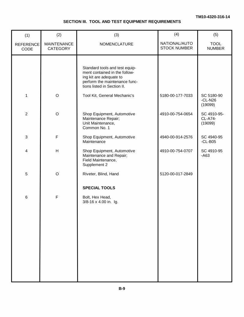
(1)
REFERENCECODE
(2)
MAINTENANCECATEGORY
(3)
NOMENCLATURE
(4)
NATIONAL/AUTOSTOCK NUMBER
(5)
TOOLNUMBER
TM10-4320-316-14SECTION III. TOOL AND TEST EQUIPMENT REQUIREMENTS
Standard tools and test equip-ment contained in the follow-ing kit are adequate toperform the maintenance func-tions listed in Section II.
1 O Tool Kit, General Mechanic's 5180-00-177-7033 SC 5180-90-CL-N26(19099)
2 O Shop Equipment, Automotive 4910-00-754-0654 SC 4910-95-Maintenance Repair; CL-A74-Unit Maintenance, (19099)Common No. 1
3 F Shop Equipment, Automotive 4940-00-914-2576 SC 4940-95Maintenance -CL-B05
4 H Shop Equipment, Automotive 4910-00-754-0707 SC 4910-95Maintenance and Repair; -A63Field Maintenance,Supplement 2
5 O Riveter, Blind, Hand 5120-00-017-2849
SPECIAL TOOLS
6 F Bolt, Hex Head,3/8-16 x 4.00 in. lg.
B-9

TM10-4320-316-14
SECTION IV. REMARKS.
REFERENCE REMARKSCODE
A Repair is limited to the replacement of components found defective during inspection.
B Use bolt for removal of fuel injector valve nozzle gasket.
C To replace cylinder block, remove all components attached to old cylinder block and attachthese components to new cylinder block.
B-10
TM10-4320-316-14
APPENDIX C
COMPONENTS OF END ITEM AND BASIC ISSUE ITEMS LISTS
SECTION I. INTRODUCTION
C-1. SCOPE.
This appendix lists components of end item and basic issue items for the DED Pump Assembly to help you inventoryitems required for safe and efficient operation.
C-2. GENERAL.
The Components of End Item and Basic Issue Items Lists are divided into the following sections:
a. Section II. Components of End Item. This listing is for informational purposes only, and is not authority torequisition replacements. These items are part of the end item, but are removed and separately packaged fortransportation or shipment. As part of the end item, these items must be with the end item whenever it is issued ortransferred between property accounts.
b. Section III Basic Issue Items (BII). These essential items required to place the DED Pump Assembly moperation, to operate it, and to do emergency repairs. Although shipped separately packaged, BII must be with thesystem during operation and whenever it is transferred between property accounts. Listing these items is your authorityto request/requisition them for replacement, based on authorization of the end item by TOE/MTOE. Illustrations arefurnished to help you find and identify the items.
C-3. EXPLANATION OF COLUMNS.
The following provides an explanation of columns found in the tabular listings:
a. Column (1) Illustration Number (Illus. Number). This column indicates the number of the illustration inwhich the item is shown.
b. Column (2) National Stock Number. Indicates the National stock number of the item to be used forrequisitioning purposes.
c. Column (3) Description. Identifies the Federal item name (in all capital letters) followed by a minimumdescription when needed. The last line below the description is the CAGEC (Commercial and Government Entity Code)(in parentheses) and the part number.
d. Column (4) Unit of Issue (U/I). Indicates how the item is issued for the National Stock Number shown incolumn two.
e. Column (5) - Quantity required (Qty Rqr). Indicates the quantity required.
C-1

TM10-4320-316-14
SECTION II. COMPONENTS OF END ITEM
1 ENCLOSURE ASSEMBLY, INLET SIDE EA 1(97403) 13229E9681
2 ENCLOSURE ASSEMBLY, OUTLET SIDE EA 1(97403) 13229E9680
3 FRAME, BOTTOM PAN EA 1(97403) 13229E9683
(5)
QTYRqr
(3)
DESCRIPTION Usable OnCAGEC and Part Number Code
(2)NATIONAL
STOCKNUMBER
(4)
U/M
(1)
ILLUSNUMBER
C-2
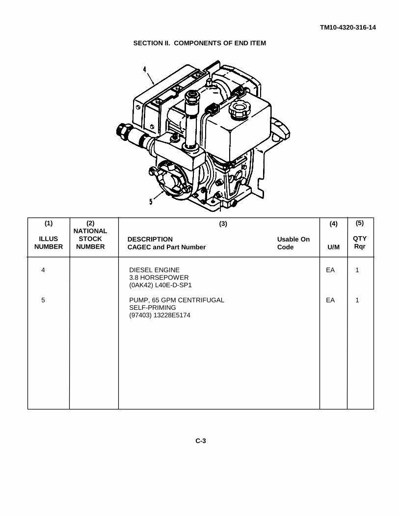
TM10-4320-316-14
SECTION II. COMPONENTS OF END ITEM
4 DIESEL ENGINE EA 13.8 HORSEPOWER(0AK42) L40E-D-SP1
5 PUMP, 65 GPM CENTRIFUGAL EA 1SELF-PRIMING(97403) 13228E5174
(5)
QTYRqr
(3)
DESCRIPTION Usable OnCAGEC and Part Number Code
(2)NATIONAL
STOCKNUMBER
(4)
U/M
(1)
ILLUSNUMBER
C-3
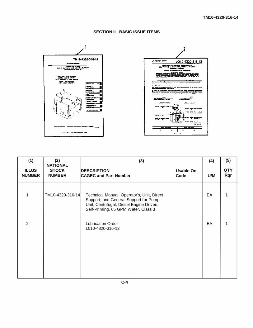
TM10-4320-316-14
SECTION II. BASIC ISSUE ITEMS
1 TM10-4320-316-14 Technical Manual: Operator's, Unit, Direct EA 1Support, and General Support for PumpUnit, Centrifugal, Diesel Engine Driven,Self-Priming, 65 GPM Water, Class 3
2 Lubrication Order EA 1L010-4320-316-12
(5)
QTYRqr
(3)
DESCRIPTION Usable OnCAGEC and Part Number Code
(2)NATIONAL
STOCKNUMBER
(4)
U/M
(1)
ILLUSNUMBER
C-4
TM10-4320-316-14
APPENDIX DADDITIONAL AUTHORIZATION LIST
SECTION I. INTRODUCTION
D-1. SCOPE.
This appendix lists additional items you are authorized for the support of the DED Pump Assembly.
D-2. GENERAL.
This list identifies items that do not have to accompany the DED Pump Assembly and that do not have to be turned inwith it. These items are all authorized to you by CTA, MTOE, TDA, or JTA
D-3. EXPLANATION OF LISTING.
National stock numbers, descriptions, and quantities are provided to help you identify and request the additional itemsyou require to support this equipment. The items are listed in alphabetical sequence by item name. If the item yourequire differs between the serial numbers of the same model, effective serial numbers are shown in the last line of thedescription. If the item required differs for different models of this equipment, the model number is shown under the"Usable On" heading in the description column.
D-1

TM10-4320-316-14
SECTION II. ADDITIONAL AUTHORIZATION LIST
NO ADDITIONAL AUTHORIZATION ITEMS ARE AUTHORIZEDFOR THE DED PUMP ASSEMBLY.
(4)QTY
AUTH
(2)DESCRIPTION Usable OnCAGE and Part Number Code
(3)
U/M
(1)NATIONAL STOCK
NUMBER
D-2

TM10-4320-316-14
APPENDIX EEXPENDABLE / DURABLE SUPPLIES AND MATERIALS LIST
SECTION I. INTRODUCTION
E-1. SCOPE.
This appendix lists expendable supplies and materials you will need to operate and maintain the DED Pump Assembly.This listing is for information only and is not authority to requisition the listed items. These items are authorized to you byCTA 50-970, Expendable Items (except medical, class V, repair parts, and heraldic items) or CTA 8-100, Army MedicalDepartment Expendable/Durable Items.
E-2. EXPLANATION OF COLUMNS.
a. Column (1) - Item number. This number is assigned to the entry in the listing and is referenced in thenarrative instructions to identify the material (e.g., "Use cleaning compound, item 5, Appendix E").
b. Column (2) - Level. This column identifies the lowest level of maintenance that requires the listed item.
C - Operator/CrewO - Unit MaintenanceF - Direct Support MaintenanceH - General Support Maintenance
c. Column (3) - National Stock Number. This is the National stock number assigned to the item which you canuse to requisition it.
d. Column (4) - Item Name, Description, Commercial and Government Entity Code (CAGEC), and PartNumber. This provides the other information you need to identify the item.
e. Column (5) - Unit of Measure (U/M). This code shows the physical measurement or count of an item, such asgallon, dozen, gross, etc.
E-1
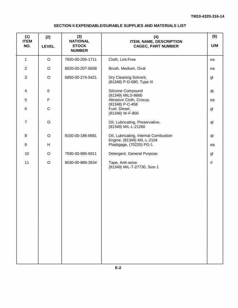
TM10-4320-316-14
SECTION II EXPENDABLE/DURABLE SUPPLIES AND MATERIALS LIST
1 O 7920-00-205-1711 Cloth, Lint-Free ea
2 O 8020-00-207-6658 Brush, Medium, Oval ea
3 O 6850-00-274-5421 Dry Cleaning Solvent, gl(81348) P-D-680, Type III
4 0 Silicone Compound qt(81349) MILS-8660
5 F Abrasive Cloth, Crocus, ea(81348) P-C-458
6 C Fuel, Diesel, gl(81348) W-F-800
7 O Oil, Lubricating, Preservative, qt(81349) MIL-L-21260
8 O 9150-00-186-6681 Oil, Lubricating, Internal Combustion qtEngine, (81349) MIL-L-2104
9 H Plastigage, (70220) PG-1 ea
10 O 7930-00-985-6911 Detergent, General Purpose gl
11 O 8030-00-889-3534 Tape, Anti-seize rl(81349) MIL-T-27730, Size 1
(5)
U/M
(4)ITEM, NAME, DESCRIPTION
CAGEC, PART NUMBER
(2)
LEVEL
(3)NATIONAL
STOCKNUMBER
(1)ITEMNO.
E-2
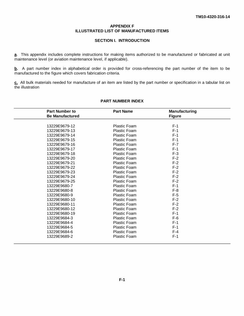
TM10-4320-316-14
APPENDIX FILLUSTRATED LIST OF MANUFACTURED ITEMS
SECTION I. INTRODUCTION
a. This appendix includes complete instructions for making items authorized to be manufactured or fabricated at unitmaintenance level (or aviation maintenance level, if applicable).
b. A part number index in alphabetical order is provided for cross-referencing the part number of the item to bemanufactured to the figure which covers fabrication criteria.
c. All bulk materials needed for manufacture of an item are listed by the part number or specification in a tabular list onthe illustration
PART NUMBER INDEX
Part Number to Part Name ManufacturingBe Manufactured Figure
13229E9679-12 Plastic Foam F-113229E9679-13 Plastic Foam F-113229E9679-14 Plastic Foam F-113229E9679-15 Plastic Foam F-113229E9679-16 Plastic Foam F-713229E9679-17 Plastic Foam F-113229E9679-18 Plastic Foam F-313229E9679-20 Plastic Foam F-213229E9679-21 Plastic Foam F-213229E9679-22 Plastic Foam F-213229E9679-23 Plastic Foam F-213229E9679-24 Plastic Foam F-213229E9679-25 Plastic Foam F-213229E9680-7 Plastic Foam F-113229E9680-8 Plastic Foam F-813229E9680-9 Plastic Foam F-513229E9680-10 Plastic Foam F-213229E9680-11 Plastic Foam F-213229E9680-12 Plastic Foam F-213229E9680-19 Plastic Foam F-113229E9684-3 Plastic Foam F-613229E9684-4 Plastic Foam F-113229E9684-5 Plastic Foam F-113229E9684-6 Plastic Foam F-413229E9689-2 Plastic Foam F-1
F-1

TM10-4320-316-14
Part Number Width Height
13229E9679-12 5.38 2.7513229E9679-13 8.94 12.0613229E9679-14 8.94 10.1313229E9679-15 9.75 11.5013229E9679-17 11.50 14.7513229E9680-7 16.00 11.6313229E9680-19 5.56 9.5013229E9684-4 3.13 8.2513229E9684-5 3.13 14.5013229E9689-2 4.69 5.19
PART NO: See Tabulation
MATERIAL: Foam, open cell, flexible polyether urethane, adhesive backed, 2.00 thick. Bulk materialpart number (97403) 13229E9692-3.
PROCEDURE: Cut foam to length and width as indicated in table.
Figure F-1.
F-2
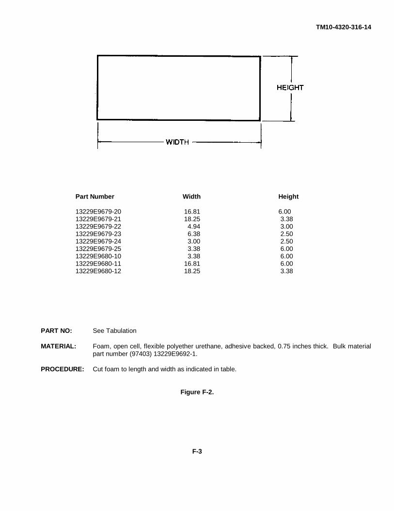
TM10-4320-316-14
Part Number Width Height
13229E9679-20 16.81 6.0013229E9679-21 18.25 3.3813229E9679-22 4.94 3.0013229E9679-23 6.38 2.5013229E9679-24 3.00 2.5013229E9679-25 3.38 6.0013229E9680-10 3.38 6.0013229E9680-11 16.81 6.0013229E9680-12 18.25 3.38
PART NO: See Tabulation
MATERIAL: Foam, open cell, flexible polyether urethane, adhesive backed, 0.75 inches thick. Bulk materialpart number (97403) 13229E9692-1.
PROCEDURE: Cut foam to length and width as indicated in table.
Figure F-2.
F-3
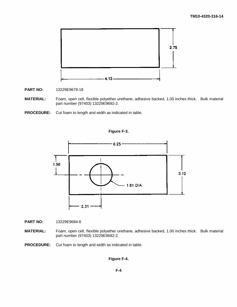
TM10-4320-316-14
PART NO: 13229E9679-18
MATERIAL: Foam, open cell, flexible polyether urethane, adhesive backed, 1.00 inches thick. Bulk materialpart number (97403) 13229E9692-2.
PROCEDURE: Cut foam to length and width as indicated in table.
Figure F-3.
PART NO: 13229E9684-6
MATERIAL: Foam, open cell, flexible polyether urethane, adhesive backed, 1.00 inches thick. Bulk materialpart number (97403) 13229E9692-2.
PROCEDURE: Cut foam to length and width as indicated in table.
Figure F-4.
F-4

TM10-4320-316-14
PART NO: 13229E9680-9
MATERIAL: Foam, open cell, flexible polyether urethane, adhesive backed, 2.00 inches thick. Bulk materialpart number (97403) 13229E9692-3.
PROCEDURE: Cut foam to length and width as indicated in table.
Figure F-5.
PART NO: 13229E9684-3
MATERIAL: Foam, open cell, flexible polyether urethane, adhesive backed, 2.00 inches thick. Bulk materialpart number (97403) 13229E9692-3.
PROCEDURE: Cut foam to length and width as indicated in table.
Figure F-6.
F-5

TM10-4320-316-14
PART NO: 13229E9679-16
MATERIAL: Foam, open cell, flexible polyether urethane, adhesive backed, 2.00 inches thick. Bulk material partnumber (97403) 13229E9692-3.
PROCEDURE: Cut foam to length and width as indicated in table.
Figure F-7.
PART NO: 13229E9680-8
MATERIAL: Foam, open cell, flexible polyether urethane, adhesive backed, 2.00 inches thick. Bulk material partnumber (97403) 13229E9692-3.
PROCEDURE: Cut foam to length and width as indicated in table.
Figure F-8.
F-6

TM10-4320-316-14
APPENDIX GTORQUE LIMITS
G-1. GENERAL. This appendix provides general torque limits for fasteners. Special torque values are indicated in themaintenance procedures for applicable components. The general torque values given in this appendix shall be usedwhen specific torque values are not indicated in the maintenance procedures.
G-2. TORQUE LIMITS. Torque limits are listed in Table G-1 for fasteners. Dry fasteners are defined as fasteners onwhich no lubricants are applied to the threads. Wet fasteners are defined as fasteners on which graphite ormolydisulphide greases or other extreme pressure lubricants are applied to the threads. Table G-2 lists the minimumbreakaway torque values for locknuts.
Table G-1. General Torque Requirements for Dry Fasteners.*
Torque Requirement in lb ft (N•m)
Bolt/Screw SAE Grade SAE Grade SAE Grade SAE GradeSize 1 or 2 5 6 or 7 8
1/4-20 UNC 5 (7) 8 (11) 10 (14) 12 (16)1/4-28 UNF 6 (8) 10 (14) 12 (16) 14 (19)
5/16 18 UNC 11 (15) 17 (23) 19 (26) 24 (33)5/16-24 UNF 13 (18) 19 (26) 23 (31) 27 (37)
3/8 16 UNC 18 (24) 31 (42) 34 (46) 44 (60)3/8-24 UNF 20 (27) 35 (47) 42 (57) 49 (66)
7/16-14 UNC 28 (38) 49 (66) 55 (75) 70 (95)7/16-20 UNF 30 (41) 55 (75) 67 (91) 78 (106)
1/2-13 UNC 39 (53) 75 (102) 85 (115) 105 (142)1/2-20 UNF 41 (56) 85 (115) 102 (138) 120 (163)
9/16-12 UNC 51 (69) 110 (149) 120 (163) 155 (210)9/16-18 UNF 55 (75) 120 (163) 145 (197) 170 (231)
5/8-11 UNC 63 (85) 150 (203) 167 (226) 210 (285)5/8-18 UNF 95 (129) 170 (231) 205 (278) 240 (325)
3/4-10 UNC 105 (142) 270 (366) 280 (380) 375 (509)3/4-16 UNF 115 (156) 295 (400) 357 (484) 420 (570)
7/8-9 UNC 160 (217) 395 (536) 440 (597) 605 (820)7/8-14 UNF 175 (237) 435 (590) 555 (753) 675 (915)
G-1

TM 10-4320-316-14
Table G-1. General Torque Requirements for Dry Fasteners.* - Continued.
Torque Requirement in lb ft (N•m)
Bolt/Screw SAE Grade SAE Grade SAE Grade SAE GradeSize 1 or 2 5 6 or 7 8
1-8 UNC 235 (319) 590 (800) 660 (895) 910 (1234)1-14 UNF 250 (339) 660 (895) 825 (1119) 990 (1342)
1-1/8-7 UNC 350 (475) 800 (1085) 1000 (1356) 1280 (1736)1-1/8-12 UNF 400 (542) 880 (1193) 1050 (1424) 1440 (1953)
1-1/4-7 UNC 500 (678) 1080 (1464) 1325 (1797) 1820 (2468)1-1/4-12 UNF 550 (746) 1125 (1526) 1325 (1797) 1820 (2712)
1-3/8-6 UNC 660 (895) 1460 (1980) 1800 (2441) 2380 (3227)1-3/8-12 UNF 740 (1003) 1680 (2278) 1960 (2658) 2720 (3688)
1-1/2-6 UNC 870 (1180) 1940 (2631) 2913 (3950) 3160 (4285)1-1/2-12 UNF 980 (1329) 2200 (2983) 3000 (4068) 3560 (4827)
* Torque given is for clean, dry threads Reduce by 10% when engine oil is used as lubricant
Table G-2. Locknut Breakaway Torque Values.
NOTETo determine breakaway torque, thread lock nut onto screw or bolt until at least two threads stick out.Locknut shall not make contact with a mating part. Stop the locknut. Torque necessary to begin turninglocknut again is the breakaway torque. Do not reuse locknuts that do not meet minimum breakawaytorque.
ThreadMinimum Breakaway Torque
Size lb-in (N•m)
10-32 2.0 (0.23)1/4-28 3.5 (0.40)
5/16-24 6.5 (0.73)3/8-24 9.5 (1.07)
7/16-20 14.0 (1.58)1/2-20 18.0 (2.03)
9/16-18 24.0 (2.71)5/8-18 32.0 (3.62)3/4-16 50.0 (5.65)7/8-14 70.0 (7.91)1-12 90.0 (10.17)
1-1/8-12 117.0 (13.22)
G-2

TM10-4320-316-14
ALPHABETICAL INDEX
Paragraph PageA
Abbreviations, List of............................................................................................1-8 1-2Access Cover Repair and Replacement ..............................................................4-18 4-28Additional Authorization List .................................................................................D-1 D-1Adjustments, Initial, Daily Checks, and Self tests .................................................2-8 2-15Air Cleaner Filter Element, Engine, Servicing ......................................................3-7 3-6Air Cleaner, Filter Element, and Air Intake Pipe Repair and Replacement ...........4-31 4-70Air Intake Hose Replacement ..............................................................................4-16 4-24Assembly and Preparation for Use ......................................................................2-7 2-12
BBaffles Replacement ............................................................................................4-21 4-34Balancer Shaft Assembly Replacement ...............................................................6-8 6-16Basic Issue Items .................................................................................................C-1 C-1Bottom Pan Frame Repair and Replacement ......................................................4-25 4-48
CCamshaft Assembly Replacement .......................................................................6-9 6-18Common Tools and Equipment, General Support ................................................6-1 6-1Common Tools and Equipment, Direct Support ...................................................5-1 5-1Common Tools and Equipment, Unit ....................................................................4-1 4-1Components of End Item List ...............................................................................C-1 C-1Compression Release Handle Replacement ........................................................4-14 4-20Control Assembly Replacement............................................................................4-15 4-22Controls and Indicators, Operator ........................................................................2-2 2-2Corrosion and Prevention Control ........................................................................1-3 1-1Crankcase Assembly Repair and Replacement ...................................................6-5 6-2Crankshaft Replacement .....................................................................................6-10 6-20Cylinder Head Assembly Repair and Replacement ..............................................5-10 5-14
DDecals and Instruction Plates ..............................................................................2-11 2-18Destruction of Army Materiel to Prevent Enemy Use ...........................................1-4 1-1
EEmergency Procedures .......................................................................................2-13 2-22Enclosure Assembly, Outlet Side Repair and Replacement .................................4-23 4-42Enclosure Assembly, Inlet Side Repair and Replacement ....................................4-22 4-38Equipment Data ...................................................................................................1-11 1-4Equipment Characteristics, Capabilities, and Features ........................................1-9 1-2Exhaust Silencer Repair and Replacement ..........................................................4-32 4-72Exhaust Extension Replacement .........................................................................4-17 4-26Expendable / Durables Supplies and Materials List ..............................................E-1 E-1
Alphabetical Index- 1

TM10-4320-316-14
ALPHABETICAL INDEX
Paragraph Page
F
Flywheel Replacement ........................................................................................5-11 5-22Fuel Tank Assembly Repair and Replacement ....................................................4-27 4-60Fuel Filter, Inlet Replacement ..............................................................................4-28 4-64Fuel Injector Pump Replacement ........................................................................4-34 4-78Fuel Injector Valve Assembly Replacement .........................................................5-8 5-6Fuel Inlet Filter, Servicing ....................................................................................3-6 3-5Fuel Cock and Fuel Filter, Outlet Replacement ...................................................4-29 4-66Fuel Lines Replacement.......................................................................................4-30 4-68
G
Governor Assembly Repair and Replacement .....................................................6-7 6-12
IIdent Plates Replacement ....................................................................................4-12 4-16Illustrated List of Manufactured items ..................................................................F-1 F-1Installation Instructions ........................................................................................4-6 4-3
LLube Oil Strainer Repair and Replacement ..........................................................4-35 4-80Lube Oil Pump Repair and Replacement .............................................................6-7 6-12Lubrication ..........................................................................................................4-7 4-4
MMaintenance Allocation Chart...............................................................................B-1 B-1Maintenance Forms and Procedures ...................................................................1-2 1-1Major Components, Location and Description ......................................................1-10 1-2Mounting Plate Repair and Replacement .............................................................5-7 5-4Movement, Preparation for ..................................................................................2-10 2-18
N
Nomenclature Cross-Reference............................................................................1-7 1-2Nuclear, Biological, and Chemical (NBC) Decontamination Procedures ..............2-14 2-22
O
Oil Drain Repair and Replacement ......................................................................4-20 4-32Oil Cap/Gauge Repair and Replacement .............................................................4-36 4-82Operating Procedures ..........................................................................................2-9 2-15Operation Under Unusual Weather ......................................................................2-12 2-20
Alphabetical Index - 2
TM10-4320-316-14
ALPHABETICAL INDEX
Paragraph Page
P
Piston and Connecting Rod Assembly Repair and Replacement ..........................6-6 6-6Preventive Maintenance Checks and Services, Operator ....................................2-4 2-4Preventive Maintenance Checks and Services, Unit.............................................4-9 4-5Pump Assembly, Repair and Replacement...........................................................4-26 4-54Pump Inlet/Outlet Piping Repair and Replacement ..............................................4-24 4-46Pump Drain Repair and Replacement .................................................................4-19 4-30
R
Recoil Starter and Cooling Fan Case Repair and Replacement ...........................4-33 4-74References ..........................................................................................................A-1 A-1Regulator Bracket Assembly Repair, Adjustment, and Replacement ...................5-9 5-10Reporting Equipment Improvement Recommendations (EIR's) ...........................1-6 1-1Roll-Over Frame Replacement ............................................................................4-13 4-18
S
Service Upon Receipt ..........................................................................................4-5 4-2Site and Shelter Requirements ............................................................................4-4 4-1Special Tools, TMDE, and Support Equipment ....................................................4-2 4-1Storage or Shipment, Preparation for ..................................................................4-37 4-84Storage of Equipment, Administrative .................................................................4-38 4-84Storage or Shipment, Preparation for ..................................................................1-5 1-1Suction Flange Assembly Repair and Replacement .............................................4-24 4-46
T
Theory of Operations ...........................................................................................1-12 1-5Torque Limits ......................................................................................................G-1 G-1Troubleshooting, Operator....................................................................................3-4 3-1Troubleshooting, Unit ..........................................................................................4-10 4-9Troubleshooting, Direct Support ...........................................................................5-5 5-1
Alphabetical Index - 3/ (Alphabetical Index - 4 Blank)


The Metric System and Equivalents
Linear Measure Liquid Measure
1 centiliter = 10 milliters = .34 fl. ounce1 centimeter = 10 millimeters = .39 inch 1 deciliter = 10 centiliters = 3.38 fl. ounces1 decimeter = 10 centimeters = 3.94 inches 1 liter = 10 deciliters = 33.81 fl. ounces1 meter = 10 decimeters = 39.37 inches 1 dekaliter = 10 liters = 2.64 gallons1 dekameter = 10 meters = 32.8 feet 1 hectoliter = 10 dekaliters = 26.42 gallons1 hectometer = 10 dekameters = 328.08 feet 1 kiloliter = 10 hectoliters = 264.18 gallons1 kilometer = 10 hectometers = 3,280.8 feet
Square MeasureWeights
1 sq. centimeter = 100 sq. millimeters = .155 sq. inch1 centigram = 10 milligrams = .15 grain 1 sq. decimeter = 100 sq. centimeters = 15.5 sq. inches1 decigram = 10 centigrams = 1.54 grains 1 sq. meter (centare) = 100 sq. decimeters = 10.76 sq. feet1 gram = 10 decigram = .035 ounce 1 sq. dekameter (are) = 100 sq. meters = 1,076.4 sq. feet1 decagram = 10 grams = .35 ounce 1 sq. hectometer (hectare) = 100 sq. dekameters = 2.47acres1 hectogram = 10 decagrams = 3.52 ounces 1 sq. kilometer = 100 sq. hectometers = .386 sq. mile1 kilogram = 10 hectograms = 2.2 pounds1 quintal = 100 kilograms = 220.46 pounds Cubic Measure1 metric ton = 10 quintals = 1.1 short tons
1 cu. centimeter = 1000 cu. millimeters = .06 cu. inch1 cu. decimeter = 1000 cu. centimeters = 61.02 cu.inches1 cu. meter = 1000 cu. decimeters = 35.31 cu. feet
Approximate Conversion Factors
To change To Multiply by To change To Multiply by
inches centimeters 2.540 ounce-inches Newton-meters .007062feet meters .305 centimeters inches .394yards meters .914 meters feet 3.280miles kilometers 1.609 meters yards 1.094square inches square centimeters 6.451 kilometers miles .621square feet square meters .093 square centimeters square inches .155square yards square meters .836 square meters square feet 10.764square miles square kilometers 2.590 square meters square yards 1.196acres square hectometers .405 square kilometers square miles .386cubic feet cubic meters .028 square hectometers acres 2.471cubic yards cubic meters .765 cubic meters cubic feet 35.315fluid ounces milliliters 29,573 cubic meters cubic yards 1.308pints liters .473 milliliters fluid ounces .034quarts liters .946 liters pints 2.113gallons liters 3.785 liters quarts 1.057ounces grams 28.349 liters gallons .264pounds kilograms .454 grams ounces .035short tons metric tons .907 kilograms pounds 2.205pound-feet Newton-meters 1.356 metric tons short tons 1.102pound-inches Newton-meters .11296
Temperature (Exact)
°F Fahrenheit 5/9 (after Celsius °Ctemperature subtracting 32) temperature

PIN: 072234-000

This fine document...
Was brought to you by me:
Liberated Manuals -- free army and government manuals
Why do I do it? I am tired of sleazy CD-ROM sellers, who take publicly available information, slap “watermarks” and other junk on it, and sell it. Those masters of search engine manipulation make sure that their sites that sell free information, come up first in search engines. They did not create it... They did not even scan it... Why should they get your money? Why are not letting you give those free manuals to your friends?
I am setting this document FREE. This document was made by the US Government and is NOT protected by Copyright. Feel free to share, republish, sell and so on.
I am not asking you for donations, fees or handouts. If you can, please provide a link to liberatedmanuals.com, so that free manuals come up first in search engines:
<A HREF=http://www.liberatedmanuals.com/>Free Military and Government Manuals</A>
– SincerelyIgor Chudovhttp://igor.chudov.com/
– Chicago Machinery Movers