Embed Size (px)
Citation preview

Critical Power
User Manual Uninterruptible Power Supply
GE Consumer & Industrial SA General Electric Company CH – 6595 Riazzino (Locarno) Switzerland T +41 (0)91 / 850 51 51 F +41 (0)91 / 850 52 52
www.gecriticalpower.com
imagination at work
TLESM_030-180_UPS front_01

Critical Power
Modifications reserved Page 2/69
GE_UPS_OPM_TLE_MCE_30K_M18_1GB_V020.docx User Manual TLE Modular Series 30 - 180 CE S1
Model: TLE Modular Series 30 - 180 CE S1
Issued by: Product Document Department – Riazzino - CH
Approved by: R & D Department – Riazzino - CH
Date of issue: 08.05.2017
File name: GE_UPS_OPM_TLE_MCE_30K_M18_1GB_V020
Revision: 2.0 (RMX V1.2)
Identification No.: 8600083677P
Up-dating
Revision Concern Date
2.0 “Secure Deployment Guide” and “UPS unpacking” 08.05.2017
COPYRIGHT © 2017 by GE Consumer & Industrial SA All rights reserved.
The information contained in this publication is intended solely for the purposes indicated.
The present publication and any other documentation supplied with the UPS system is not to be reproduced, either in part or in its entirety, without the prior written consent of GE.
The illustrations and plans describing the equipment are intended as general reference only and are not necessarily complete in every detail.
The content of this publication may be subject to modification without prior notice.

Critical Power
Modifications reserved Page 3/69
GE_UPS_OPM_TLE_MCE_30K_M18_1GB_V020.docx User Manual TLE Modular Series 30 - 180 CE S1
Dear Customer,
We thank you for selecting our products and are pleased to count you amongst our very valued customers at GE. We trust that the use of the TLE Modular Series 30 - 180 Uninterruptible Power Supply System, developed and produced to the highest standards of quality, will give you complete satisfaction. Please carefully read the User Manual. It contains all the necessary information about the installation of the UPS.
Thank you for choosing GE !
Distributed by: Your service contact:
g
GE Consumer & Industrial SA General Electric Company
CH – 6595 Riazzino (Locarno) Switzerland
Critical Power
Modifications reserved Page 4/69
GE_UPS_OPM_TLE_MCE_30K_M18_1GB_V020.docx User Manual TLE Modular Series 30 - 180 CE S1
Preface Congratulations on your choice of a TLE Modular Series 30 - 180 Uninterruptible Power Supply (UPS). It will keep you away from any trouble due to unexpected power problems. This manual describes how to prepare the installation site, provides weight and dimensions and procedures for moving, installing and connecting the UPS, and details of maintenance procedures suggested to preserve maximum reliability.
It explains the function of the UPS module, the purpose and location of the switches, the meaning of the system events related to the front panel indication, and provides procedures for starting and stopping the equipment.
While every care has been taken to ensure the completeness and accuracy of this manual, GE assumes no responsibility or liability for any losses or damages resulting from the use of the information contained in this document.
WARNING!
TLE Modular Series 30 - 180 is a product for restricted sales distribution to informed partners.
Installation restrictions or additional measures may be needed to prevent disturbances.
We recommend that this manual is kept next to the UPS for future references. If any problems are encountered with the procedures contained in this manual, please contact your GE SERVICE CENTRE before you proceed. This document shall not be copied or reproduced without the permission of GE. Due to technical improvements, some of the information contained in this manual may be changed without notice.
Safety instructions
Carefully read the safety instructions contained on the following page before the installation, start-up and maintenance of the UPS, options and battery. Pay attention to the rectangular boxes included in the text: They contain important information or warning concerning electrical connections and personnel safety.
Critical Power
Modifications reserved Page 5/69
GE_UPS_OPM_TLE_MCE_30K_M18_1GB_V020.docx User Manual TLE Modular Series 30 - 180 CE S1
Table of content Page
1 SAFETY RULES ...................................................................................................................................................................... 7 1.1 SAFETY SYMBOLS AND WARNINGS ............................................................................................................................................................................. 9
2 LAYOUT ................................................................................................................................................................................10 2.1 LAYOUT TLE MODULAR SERIES 30 - 180 ................................................................................................................................................................ 10
3 INTRODUCTION .................................................................................................................................................................11 3.1 SYSTEM CONFIGURATION ............................................................................................................................................................................................ 11 3.2 POWER MODULE .............................................................................................................................................................................................................. 11 3.3 OPERATION MODE ........................................................................................................................................................................................................... 12
3.3.1 Normal mode ........................................................................................................................................................................................................................................ 12 3.3.2 Battery mode ........................................................................................................................................................................................................................................ 12 3.3.3 Bypass mode ........................................................................................................................................................................................................................................ 12 3.3.4 Maintenance mode (manual bypass) ....................................................................................................................................................................................... 13 3.3.5 ECO mode ............................................................................................................................................................................................................................................... 13 3.3.6 Auto-restart mode ............................................................................................................................................................................................................................. 13 3.3.7 Frequency converter mode ........................................................................................................................................................................................................... 13
3.4 UPS STRUCTURE ............................................................................................................................................................................................................... 13 3.4.1 UPS configuration............................................................................................................................................................................................................................... 13
3.5 SERVICE AND TECHNICAL SUPPORT ........................................................................................................................................................................ 14 3.6 WARRANTY ......................................................................................................................................................................................................................... 14 3.7 RECYCLING AT THE END OF SERVICE LIFE ............................................................................................................................................................. 15
4 INSTALLATION ....................................................................................................................................................................16 4.1 TRANSPORT ........................................................................................................................................................................................................................ 16
4.1.1 Dimensions and weights TLE Modular Series 30 - 180 .................................................................................................................................................... 17 4.2 DELIVERY.............................................................................................................................................................................................................................. 18 4.3 STORAGE .............................................................................................................................................................................................................................. 18
4.3.1 Storage of the UPS ............................................................................................................................................................................................................................. 18 4.3.2 Storage of the battery ...................................................................................................................................................................................................................... 18
4.4 PLACE OF INSTALLATION .............................................................................................................................................................................................. 19 4.4.1 UPS location .......................................................................................................................................................................................................................................... 19 4.4.2 Battery location ................................................................................................................................................................................................................................... 20 4.4.3 Ventilation and cooling .................................................................................................................................................................................................................... 20
4.5 UNLOADING AND UNPACKING .................................................................................................................................................................................. 21 4.5.1 Moving and unpacking of the UPS cabinet ........................................................................................................................................................................... 21 4.5.2 Unpacking power module .............................................................................................................................................................................................................. 23
4.6 POSITIONING OF THE TLE MODULAR SERIES 30 - 180..................................................................................................................................... 24 4.6.1 Positioning cabinet ............................................................................................................................................................................................................................ 24 4.6.2 Installing power module ................................................................................................................................................................................................................. 25
4.7 BATTERY INSTALLATION ................................................................................................................................................................................................ 26 4.8 CABLE ENTRY ..................................................................................................................................................................................................................... 26 4.9 POWER CABLES................................................................................................................................................................................................................. 27
4.9.1 Mains input connection ................................................................................................................................................................................................................... 27 4.9.2 Specifications for power cables size ......................................................................................................................................................................................... 29 4.9.3 Specifications for power cables terminal ............................................................................................................................................................................... 29 4.9.4 Line protections ................................................................................................................................................................................................................................... 29 4.9.5 Connection of the power cables ................................................................................................................................................................................................. 30
4.10 CONTROL AND COMMUNICATION CABLES ........................................................................................................................................................... 31 4.10.1 Dry contact interface ........................................................................................................................................................................................................................ 32
4.10.1.1 Interface of battery and environmental temperature detection ...................................................................................................................................................... 33 4.10.1.2 Remote EPO (Emergency Power Off) input port .......................................................................................................................................................................................... 33 4.10.1.3 UPS internal function .................................................................................................................................................................................................................................................. 33 4.10.1.4 BCB input port................................................................................................................................................................................................................................................................. 34 4.10.1.5 Battery warning output dry contact interface ............................................................................................................................................................................................. 34 4.10.1.6 General alarm output dry contact interface ................................................................................................................................................................................................. 34 4.10.1.1 UPS internal function .................................................................................................................................................................................................................................................. 34
4.10.2 Communication interface .............................................................................................................................................................................................................. 35 4.10.2.1 SNMP card ........................................................................................................................................................................................................................................................................ 35
4.11 INSTALLATION OF THE PARALLEL SYSTEM ............................................................................................................................................................ 36 5 UPS AND POWER MODULE CONTROL PANEL ...............................................................................................................37
5.1 LCD PANEL OF THE POWER MODULE ..................................................................................................................................................................... 37 5.1.1 LED indicator ......................................................................................................................................................................................................................................... 37 5.1.2 Control and operation keys ........................................................................................................................................................................................................... 38 5.1.3 LCD Display ............................................................................................................................................................................................................................................ 38
5.2 UPS CONTROL PANEL ..................................................................................................................................................................................................... 40 5.2.1 LED indicator ......................................................................................................................................................................................................................................... 41 5.2.2 Control and operation keys ........................................................................................................................................................................................................... 41 5.2.3 LCD touch screen ............................................................................................................................................................................................................................... 42
Critical Power
Modifications reserved Page 6/69
GE_UPS_OPM_TLE_MCE_30K_M18_1GB_V020.docx User Manual TLE Modular Series 30 - 180 CE S1
5.3 MAIN MENU ........................................................................................................................................................................................................................ 44 5.3.1 Cabinet ..................................................................................................................................................................................................................................................... 44 5.3.2 Module ..................................................................................................................................................................................................................................................... 46 5.3.3 Setting ...................................................................................................................................................................................................................................................... 48 5.3.4 Log ............................................................................................................................................................................................................................................................. 49 5.3.5 Operate .................................................................................................................................................................................................................................................... 50 5.3.6 Scope ........................................................................................................................................................................................................................................................ 52
6 OPERATIONS .......................................................................................................................................................................53 6.1 UPS START-UP ................................................................................................................................................................................................................... 53
6.1.1 Start in Normal mode ....................................................................................................................................................................................................................... 53 6.1.2 Start from battery ............................................................................................................................................................................................................................... 54
6.2 PROCEDURE FOR SWITCHING BETWEEN OPERATION MODES .................................................................................................................... 55 6.2.1 Switching the UPS from Normal mode into Battery mode ............................................................................................................................................ 55 6.2.2 Switching the UPS from Normal mode into Bypass mode ............................................................................................................................................ 55 6.2.3 Switching the UPS into Normal mode from Bypass mode ............................................................................................................................................ 55 6.2.4 Switching the UPS from Normal mode into Maintenance Bypass mode ............................................................................................................... 56 6.2.5 Switching the UPS into Normal Mode from Maintenance Bypass Mode ............................................................................................................... 56
6.3 BATTERY MANUAL............................................................................................................................................................................................................ 57 6.4 EPO – EMERGENCY POWER OFF ................................................................................................................................................................................ 58
7 MAINTENANCE ...................................................................................................................................................................59 7.1 GENERAL MAINTENANCE .............................................................................................................................................................................................. 59 7.2 SERVICE CHECK................................................................................................................................................................................................................. 59 7.3 BATTERY MAINTENANCE ............................................................................................................................................................................................... 60
8 OPTION ................................................................................................................................................................................61 8.1 OPTIONS GENERAL VIEW .............................................................................................................................................................................................. 61 8.2 OPTIONS ASSEMBLY AND CONNECTION ............................................................................................................................................................... 62
8.2.1 Battery cabinet 1x33Ah/ 2x33Ah / 3x33Ah ........................................................................................................................................................................... 62 8.2.2 Empty battery cabinet ..................................................................................................................................................................................................................... 63
9 SECURE DEPLOYMENT GUIDE..........................................................................................................................................64 9.1 INTRODUCTION ................................................................................................................................................................................................................. 64 9.2 GENERAL RECOMMENDATIONS ................................................................................................................................................................................. 64 9.3 CHECKLIST .......................................................................................................................................................................................................................... 65 9.4 COMMUNICATION REQUIREMENTS .......................................................................................................................................................................... 65 9.5 SECURITY CAPABILITIES ................................................................................................................................................................................................. 66
9.5.1 PHYSICAL SECURITY PERIMETER PROTECTION ..................................................................................................................................................................... 66 9.5.2 ELECTRONIC SECURITY PERIMETER PROTECTION ............................................................................................................................................................... 66 9.5.3 PASSWORD MANAGEMENT ............................................................................................................................................................................................................ 67
9.6 CONFIGURATION HARDENING ................................................................................................................................................................................... 67 9.7 NETWORK BANDWIDTH LIMITING ............................................................................................................................................................................ 67 9.8 SOFTWARE UPDATES AND PATCH MANAGEMENT ............................................................................................................................................ 67 9.9 GOVERNMENT AGENCIES AND STANDARDS ORGANIZATIONS .................................................................................................................... 67
10 NOTES ..................................................................................................................................................................................68 10.1 NOTES FORM ...................................................................................................................................................................................................................... 68
11 ANNEX .................................................................................................................................................................................69 11.1 CD-ROM ................................................................................................................................................................................................................................ 69
Critical Power
Modifications reserved Page 7/69
GE_UPS_OPM_TLE_MCE_30K_M18_1GB_V020.docx User Manual TLE Modular Series 30 - 180 CE S1
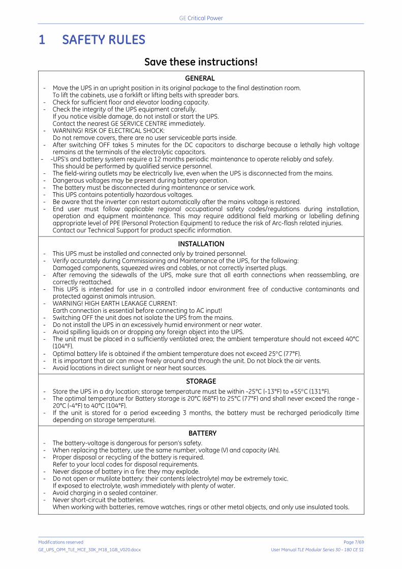
1 SAFETY RULES
Save these instructions!
GENERAL
- Move the UPS in an upright position in its original package to the final destination room. To lift the cabinets, use a forklift or lifting belts with spreader bars.
- Check for sufficient floor and elevator loading capacity. - Check the integrity of the UPS equipment carefully.
If you notice visible damage, do not install or start the UPS. Contact the nearest GE SERVICE CENTRE immediately.
- WARNING! RISK OF ELECTRICAL SHOCK: Do not remove covers, there are no user serviceable parts inside.
- After switching OFF takes 5 minutes for the DC capacitors to discharge because a lethally high voltage remains at the terminals of the electrolytic capacitors.
-UPS’s and battery system require a 12 months periodic maintenance to operate reliably and safely. This should be performed by qualified service personnel.
- The field-wiring outlets may be electrically live, even when the UPS is disconnected from the mains. - Dangerous voltages may be present during battery operation. - The battery must be disconnected during maintenance or service work. - This UPS contains potentially hazardous voltages. - Be aware that the inverter can restart automatically after the mains voltage is restored. - End user must follow applicable regional occupational safety codes/regulations during installation,
operation and equipment maintenance. This may require additional field marking or labelling defining appropriate level of PPE (Personal Protection Equipment) to reduce the risk of Arc-flash related injuries. Contact our Technical Support for product specific information.
INSTALLATION
- This UPS must be installed and connected only by trained personnel. - Verify accurately during Commissioning and Maintenance of the UPS, for the following:
Damaged components, squeezed wires and cables, or not correctly inserted plugs. - After removing the sidewalls of the UPS, make sure that all earth connections when reassembling, are
correctly reattached. - This UPS is intended for use in a controlled indoor environment free of conductive contaminants and
protected against animals intrusion. - WARNING! HIGH EARTH LEAKAGE CURRENT:
Earth connection is essential before connecting to AC input! - Switching OFF the unit does not isolate the UPS from the mains. - Do not install the UPS in an excessively humid environment or near water. - Avoid spilling liquids on or dropping any foreign object into the UPS. - The unit must be placed in a sufficiently ventilated area; the ambient temperature should not exceed 40°C
(104°F). - Optimal battery life is obtained if the ambient temperature does not exceed 25°C (77°F). - It is important that air can move freely around and through the unit. Do not block the air vents. - Avoid locations in direct sunlight or near heat sources.
STORAGE
- Store the UPS in a dry location; storage temperature must be within -25°C (-13°F) to +55°C (131°F). - The optimal temperature for Battery storage is 20°C (68°F) to 25°C (77°F) and shall never exceed the range -
20°C (-4°F) to 40°C (104°F). - If the unit is stored for a period exceeding 3 months, the battery must be recharged periodically (time
depending on storage temperature).
BATTERY
- The battery-voltage is dangerous for person’s safety. - When replacing the battery, use the same number, voltage (V) and capacity (Ah). - Proper disposal or recycling of the battery is required.
Refer to your local codes for disposal requirements. - Never dispose of battery in a fire: they may explode. - Do not open or mutilate battery: their contents (electrolyte) may be extremely toxic.
If exposed to electrolyte, wash immediately with plenty of water. - Avoid charging in a sealed container. - Never short-circuit the batteries.
When working with batteries, remove watches, rings or other metal objects, and only use insulated tools.

Critical Power
Modifications reserved Page 8/69
GE_UPS_OPM_TLE_MCE_30K_M18_1GB_V020.docx User Manual TLE Modular Series 30 - 180 CE S1
Safety instructions when working with battery
EXTERNAL BATTERY MUST BE INSTALLED AND CONNECTED TO THE UPS BY QUALIFIED SERVICE PERSONNEL. INSTALLATION PERSONNEL MUST READ THIS ENTIRE SECTION BEFORE HANDLING THE UPS AND BATTERY.
DANGER! Full voltage and current are always present at the battery terminals. The battery used in this system can provide dangerous voltages, extremely high currents and a risk of electric shock. If the terminals are shorted together or to ground, they may cause severe injury. You must be extremely careful to avoid electric shock and burns caused by contacting battery terminals or shorting terminals during battery installation. Do not touch uninsulated battery terminals.
A qualified service person, who is familiar with battery systems and required precautions, must install and service the battery. The installation must conform to national and local codes. Keep unauthorised personnel away from the battery.
The qualified service person must take these precautions: 1 Wear protective clothing, such as rubber gloves and boots and protective eye wear.
Batteries contain caustic acids and toxic materials and can rupture or leak if mistreated. Remove rings and metal wristwatches or other metal objects and jewellery. Do not carry metal objects in your pockets where the objects can fall into the battery cabinet. High energy through conductive materials could cause severe burns.
2 Tools must have insulated handles and must be insulated so that they will not short battery terminals. Do not allow a tool to short between individual or separate battery terminals or to the cabinet or rack. Do not lay tools or metal parts on top of the battery, and do not lay them where they could fall onto the battery or into the cabinet.
3 Disconnect charging source prior to connecting or disconnecting battery terminals. Install the battery as shown on the drawing provided with the battery. When connecting cables, never allow a cable to short across a battery’s terminals, the string of battery, or to the cabinet or rack.
4 Align the cables on the battery terminals so that the cable lug will not contact any part of the cabinet or rack, even if the battery is moved. Keep the cable away from any sharp metal edges.
5 Install the battery cables in such a way that the UPS or battery cabinet doors cannot pinch them.
6 Do not connect the battery terminal to Ground. If any battery terminal is inadvertently grounded, remove the source of the ground. Contacting any part of a grounded battery can cause a risk of electric shock.
7 Determine if battery is inadvertently grounded. If inadvertently grounded, remove source from ground. Contact with any part of a grounded battery can result in electrical shock. The likelihood of such shock can be reduced if such grounds are removed during installation and maintenance.
8 To reduce the risk of fire or electric shock, install the battery in a temperature and humidity controlled indoor area, free of contaminants.
9 Battery system chassis ground (earth) must be connected to the UPS chassis ground (earth). If you use conduits, this ground conductor must be routed in the same conduit as the battery conductors.
10 Where conductors may be exposed to physical damage, protect the conductors in accordance with all applicable codes.
11 If you are replacing the battery or repairing battery connections, shut OFF the UPS and remove the battery fuses.
Critical Power
Modifications reserved Page 9/69
GE_UPS_OPM_TLE_MCE_30K_M18_1GB_V020.docx User Manual TLE Modular Series 30 - 180 CE S1
1.1 SAFETY SYMBOLS AND WARNINGS
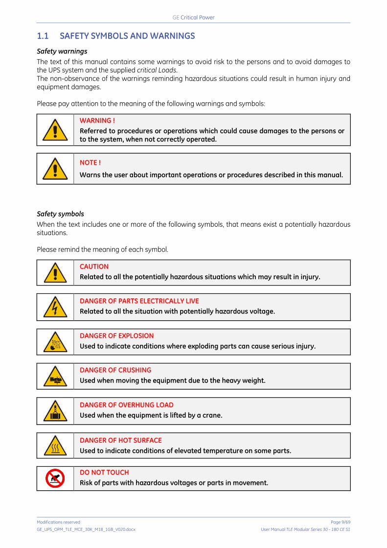
Safety warnings The text of this manual contains some warnings to avoid risk to the persons and to avoid damages to the UPS system and the supplied critical Loads. The non-observance of the warnings reminding hazardous situations could result in human injury and equipment damages. Please pay attention to the meaning of the following warnings and symbols:
WARNING ! Referred to procedures or operations which could cause damages to the persons or to the system, when not correctly operated.
NOTE !
Warns the user about important operations or procedures described in this manual.
Safety symbols When the text includes one or more of the following symbols, that means exist a potentially hazardous situations. Please remind the meaning of each symbol.
CAUTION Related to all the potentially hazardous situations which may result in injury.
DANGER OF PARTS ELECTRICALLY LIVE Related to all the situation with potentially hazardous voltage.
DANGER OF EXPLOSION Used to indicate conditions where exploding parts can cause serious injury.
DANGER OF CRUSHING Used when moving the equipment due to the heavy weight.
DANGER OF OVERHUNG LOAD Used when the equipment is lifted by a crane.
DANGER OF HOT SURFACE Used to indicate conditions of elevated temperature on some parts.
DO NOT TOUCH Risk of parts with hazardous voltages or parts in movement.
Critical Power
Modifications reserved Page 10/69
GE_UPS_OPM_TLE_MCE_30K_M18_1GB_V020.docx User Manual TLE Modular Series 30 - 180 CE S1
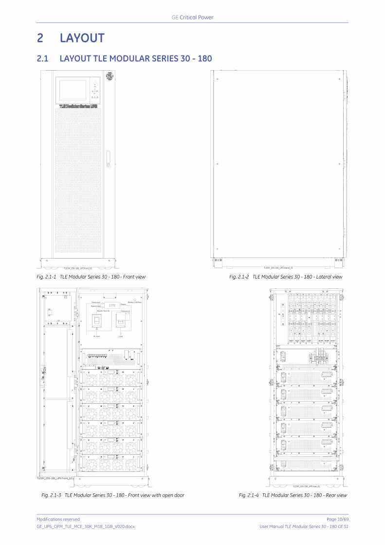
2 LAYOUT 2.1 LAYOUT TLE MODULAR SERIES 30 - 180
Fig. 2.1-1 TLE Modular Series 30 - 180 - Front view
Fig. 2.1-2 TLE Modular Series 30 - 180 - Lateral view
Fig. 2.1-3 TLE Modular Series 30 - 180 - Front view with open door
Fig. 2.1-4 TLE Modular Series 30 - 180 - Rear view
TLESM_030-180_UPS front_01 TLESM_030-180_UPS lateral_01
TLESM_030-180_UPS Front_02
LoadAC input
Battery Cold Start
Bypass Input Q5
Mains InputOutput
Bypass Input
TLESM_030-180_UPS rear_01
Critical Power
Modifications reserved Page 11/69
GE_UPS_OPM_TLE_MCE_30K_M18_1GB_V020.docx User Manual TLE Modular Series 30 - 180 CE S1
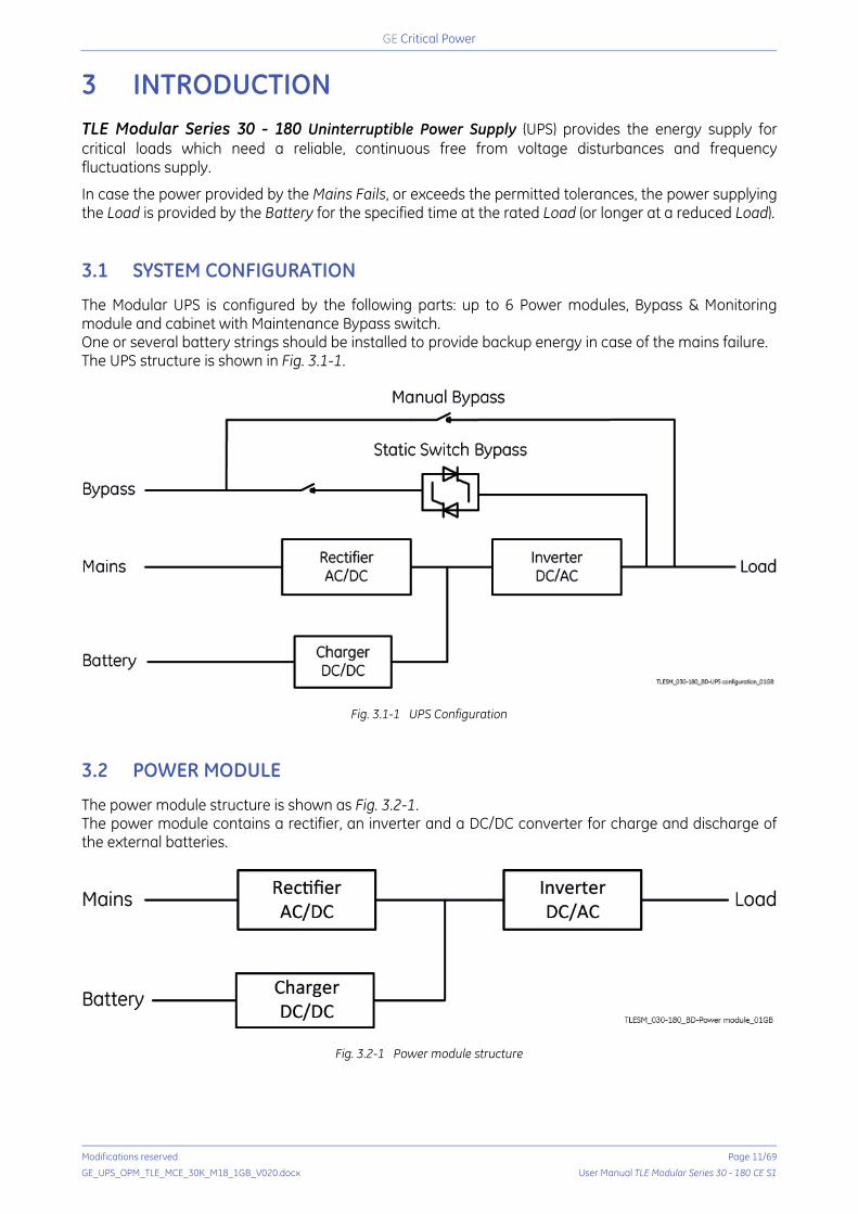
3 INTRODUCTION TLE Modular Series 30 - 180 Uninterruptible Power Supply (UPS) provides the energy supply for critical loads which need a reliable, continuous free from voltage disturbances and frequency fluctuations supply.
In case the power provided by the Mains Fails, or exceeds the permitted tolerances, the power supplying the Load is provided by the Battery for the specified time at the rated Load (or longer at a reduced Load). 3.1 SYSTEM CONFIGURATION
The Modular UPS is configured by the following parts: up to 6 Power modules, Bypass & Monitoring module and cabinet with Maintenance Bypass switch. One or several battery strings should be installed to provide backup energy in case of the mains failure. The UPS structure is shown in Fig. 3.1-1.
Fig. 3.1-1 UPS Configuration 3.2 POWER MODULE
The power module structure is shown as Fig. 3.2-1. The power module contains a rectifier, an inverter and a DC/DC converter for charge and discharge of the external batteries.
Fig. 3.2-1 Power module structure
Critical Power
Modifications reserved Page 12/69
GE_UPS_OPM_TLE_MCE_30K_M18_1GB_V020.docx User Manual TLE Modular Series 30 - 180 CE S1
3.3 OPERATION MODE
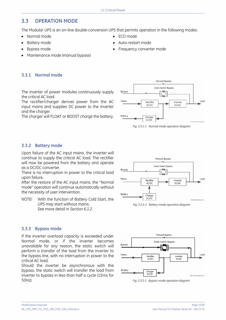
The Modular UPS is an on-line double-conversion UPS that permits operation in the following modes: • Normal mode • ECO mode • Battery mode • Auto-restart mode • Bypass mode • Frequency converter mode • Maintenance mode (manual bypass) 3.3.1 Normal mode
The inverter of power modules continuously supply the critical AC load. The rectifier/charger derives power from the AC input mains and supplies DC power to the inverter and the charger. The charger will FLOAT or BOOST charge the battery.
Fig. 3.3.1-1 Normal mode operation diagram
3.3.2 Battery mode
Upon failure of the AC input mains, the inverter will continue to supply the critical AC load. The rectifier will now be powered from the battery and operate as a DC/DC converter. There is no interruption in power to the critical load upon failure. After the restore of the AC input mains, the “Normal mode” operation will continue automatically without the necessity of user intervention.
NOTE! With the function of Battery Cold Start, the UPS may start without mains. See more detail in Section 6.1.2.
Fig. 3.3.2-1 Battery mode operation diagram
3.3.3 Bypass mode
If the inverter overload capacity is exceeded under Normal mode, or if the inverter becomes unavailable for any reason, the static switch will perform a transfer of the load from the inverter to the bypass line, with no interruption in power to the critical AC load. Should the inverter be asynchronous with the bypass, the static switch will transfer the load from inverter to bypass in less than half a cycle (15ms for 50Hz).
Fig. 3.3.3-1 Bypass mode operation diagram
Critical Power
Modifications reserved Page 13/69
GE_UPS_OPM_TLE_MCE_30K_M18_1GB_V020.docx User Manual TLE Modular Series 30 - 180 CE S1
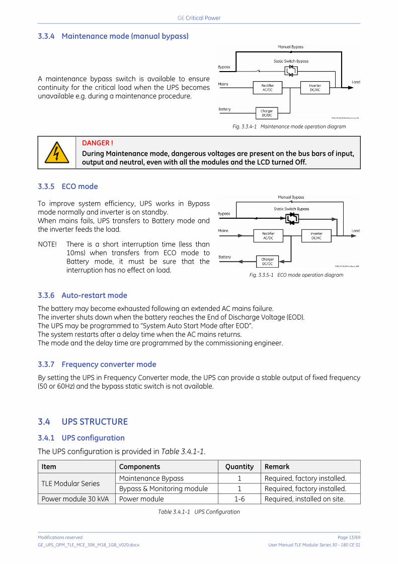
3.3.4 Maintenance mode (manual bypass)
A maintenance bypass switch is available to ensure continuity for the critical load when the UPS becomes unavailable e.g. during a maintenance procedure.
Fig. 3.3.4-1 Maintenance mode operation diagram
DANGER ! During Maintenance mode, dangerous voltages are present on the bus bars of input, output and neutral, even with all the modules and the LCD turned Off.
3.3.5 ECO mode
To improve system efficiency, UPS works in Bypass mode normally and inverter is on standby. When mains fails, UPS transfers to Battery mode and the inverter feeds the load. NOTE! There is a short interruption time (less than
10ms) when transfers from ECO mode to Battery mode, it must be sure that the interruption has no effect on load.
Fig. 3.3.5-1 ECO mode operation diagram
3.3.6 Auto-restart mode
The battery may become exhausted following an extended AC mains failure. The inverter shuts down when the battery reaches the End of Discharge Voltage (EOD). The UPS may be programmed to “System Auto Start Mode after EOD”. The system restarts after a delay time when the AC mains returns. The mode and the delay time are programmed by the commissioning engineer.
3.3.7 Frequency converter mode
By setting the UPS in Frequency Converter mode, the UPS can provide a stable output of fixed frequency (50 or 60Hz) and the bypass static switch is not available. 3.4 UPS STRUCTURE
3.4.1 UPS configuration
The UPS configuration is provided in Table 3.4.1-1.
Item Components Quantity Remark
TLE Modular Series Maintenance Bypass 1 Required, factory installed. Bypass & Monitoring module 1 Required, factory installed.
Power module 30 kVA Power module 1-6 Required, installed on site.
Table 3.4.1-1 UPS Configuration

Critical Power
Modifications reserved Page 14/69
GE_UPS_OPM_TLE_MCE_30K_M18_1GB_V020.docx User Manual TLE Modular Series 30 - 180 CE S1
3.5 SERVICE AND TECHNICAL SUPPORT
For any request of technical support please contact your local GE SERVICE CENTRE.
Stamp of your local GE SERVICE CENTRE (see page 3)
Fig. 3.5-1 Identification label
The requested data permitting to identify your UPS are marked on the identification label fixed on the front of the cabinet, behind the front door. For fast and efficient technical support please mention the data marked on the identification label.
3.6 WARRANTY
GE, operating through its authorised agents, warrants that the standard products will be free of defects in materials and workmanship for a period as per contract specifications.
NOTE !
This warranty does not cover failures of the product which result from incorrect installation, misuse, alterations by persons other than authorised agents, or abnormal working conditions.
TLESM_030-180_Label identification_01
g TLE Modular Series CE
Serial NumberAZ1180-3416-I001A
INPUTUin (Vac)Input current (A)Ip. current-recharge (A)Frequency
3W+N+PE380/400/415249/236/227310/294/28350/60Hz
OUTPUTUout (Vac)Iout (A)FrequencyPower rating
3W+N+PE380/400/415272/258/24950/60Hzmax 180kVA/162kW(30kVA*N. of Modules)
Icw 40kA
Production Year 2016
GE Consumer & Industrial SAVia Cantonale 50Riazzino (Locarno), CH-6595 Switzerland
Made in China 178 kg
LoadAC input
Battery Cold Start
Bypass Input Q5
Mains InputOutput
Bypass Input
Critical Power
Modifications reserved Page 15/69
GE_UPS_OPM_TLE_MCE_30K_M18_1GB_V020.docx User Manual TLE Modular Series 30 - 180 CE S1
3.7 RECYCLING AT THE END OF SERVICE LIFE
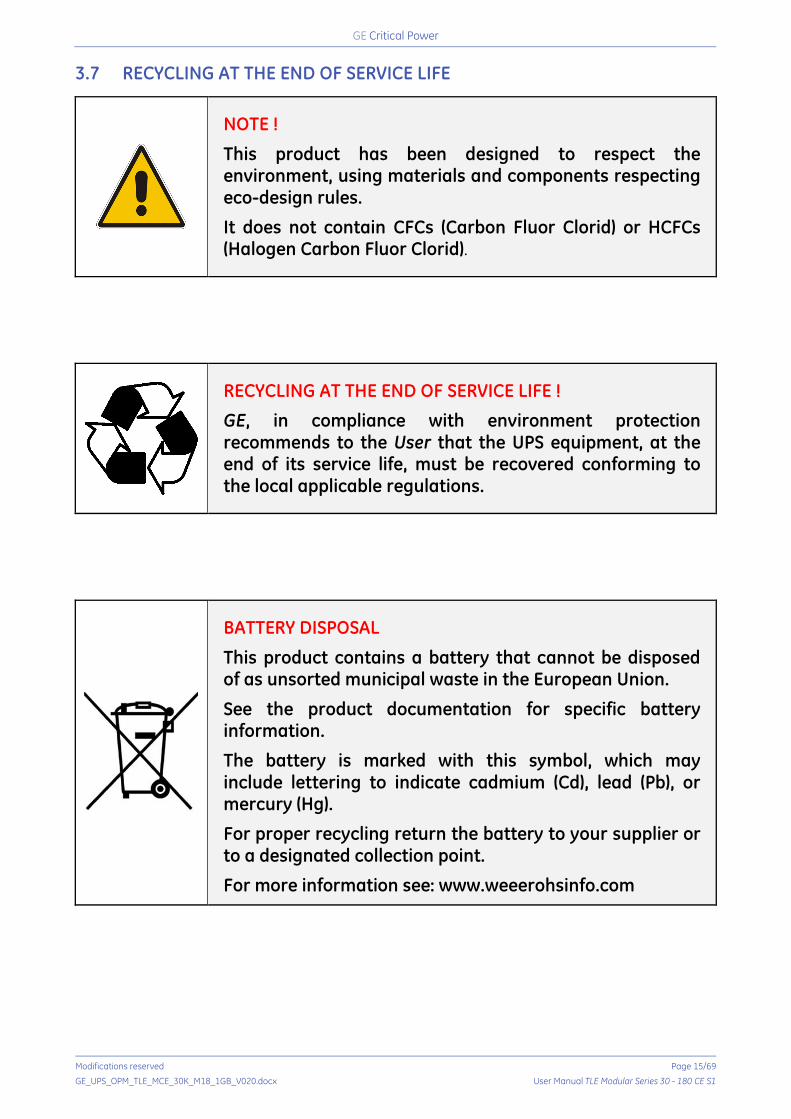
NOTE !
This product has been designed to respect the environment, using materials and components respecting eco-design rules.
It does not contain CFCs (Carbon Fluor Clorid) or HCFCs (Halogen Carbon Fluor Clorid).
RECYCLING AT THE END OF SERVICE LIFE !
GE, in compliance with environment protection recommends to the User that the UPS equipment, at the end of its service life, must be recovered conforming to the local applicable regulations.
BATTERY DISPOSAL
This product contains a battery that cannot be disposed of as unsorted municipal waste in the European Union.
See the product documentation for specific battery information.
The battery is marked with this symbol, which may include lettering to indicate cadmium (Cd), lead (Pb), or mercury (Hg).
For proper recycling return the battery to your supplier or to a designated collection point.
For more information see: www.weeerohsinfo.com

Critical Power
Modifications reserved Page 16/69
GE_UPS_OPM_TLE_MCE_30K_M18_1GB_V020.docx User Manual TLE Modular Series 30 - 180 CE S1
4 INSTALLATION 4.1 TRANSPORT
The UPS is packaged on a pallet suitable for handling with a forklift.
The UPS must be moved in upright position. Do not tilt cabinets more than +/- 10° during handling.
Move the UPS in its original package to the final destination site.
Do not stack other packages on top: this could damage the UPS.
Forklift
Fig. 4.1-1 Position of the forklift when moving the unpacked UPS
Forklift The UPS may be lifted with a forklift in upright position.
Take note of the centre of gravity marked on the package.
Crane
Fig. 4.1-2 Position of the carrying belts when moving the unpacked UPS
WARNING ! Check for sufficient floor and elevator loading capacity. Transport UPS only in upright position. Do not stack other package on top of the UPS.
Crane If the UPS has to be lifted by crane, use suitable carrying belts taking note of the centre of gravity marked on the package. Take all necessary precautions to avoid damage to the cabinet while hoisting the UPS.
WARNING ! When loading / unloading and when moving the UPS, it is forbidden:
When loading / unloading and when moving the UPS, pay attention to:
Critical Power
Modifications reserved Page 17/69
GE_UPS_OPM_TLE_MCE_30K_M18_1GB_V020.docx User Manual TLE Modular Series 30 - 180 CE S1
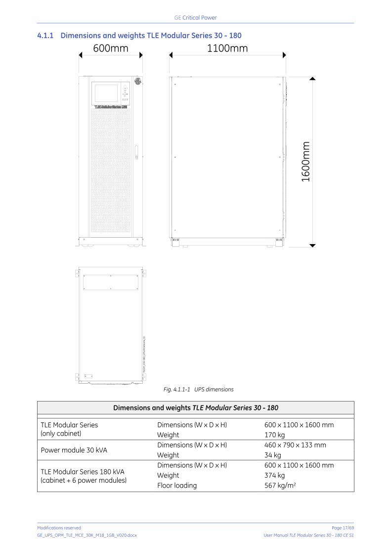
4.1.1 Dimensions and weights TLE Modular Series 30 - 180
Fig. 4.1.1-1 UPS dimensions
Dimensions and weights TLE Modular Series 30 - 180
TLE Modular Series (only cabinet)
Dimensions (W x D x H) 600 x 1100 x 1600 mm Weight 170 kg
Power module 30 kVA Dimensions (W x D x H) 460 x 790 x 133 mm Weight 34 kg
TLE Modular Series 180 kVA (cabinet + 6 power modules)
Dimensions (W x D x H) 600 x 1100 x 1600 mm Weight 374 kg Floor loading 567 kg/m2
TLES
M_0
30-1
80_U
PS d
imen
sion
s_01
600mm
1600
mm
1100mm
Critical Power
Modifications reserved Page 18/69
GE_UPS_OPM_TLE_MCE_30K_M18_1GB_V020.docx User Manual TLE Modular Series 30 - 180 CE S1
4.2 DELIVERY
When delivered, inspect the package integrity and the physical condition of the cabinet carefully. In case of any damage sustained during transport, immediately inform the carrier and contact your local GE SERVICE CENTRE. A detailed report of the damage is necessary for any insurance claim.
NOTE ! A damaged UPS MUST NEVER be installed or connected to Mains or Battery!
4.3 STORAGE
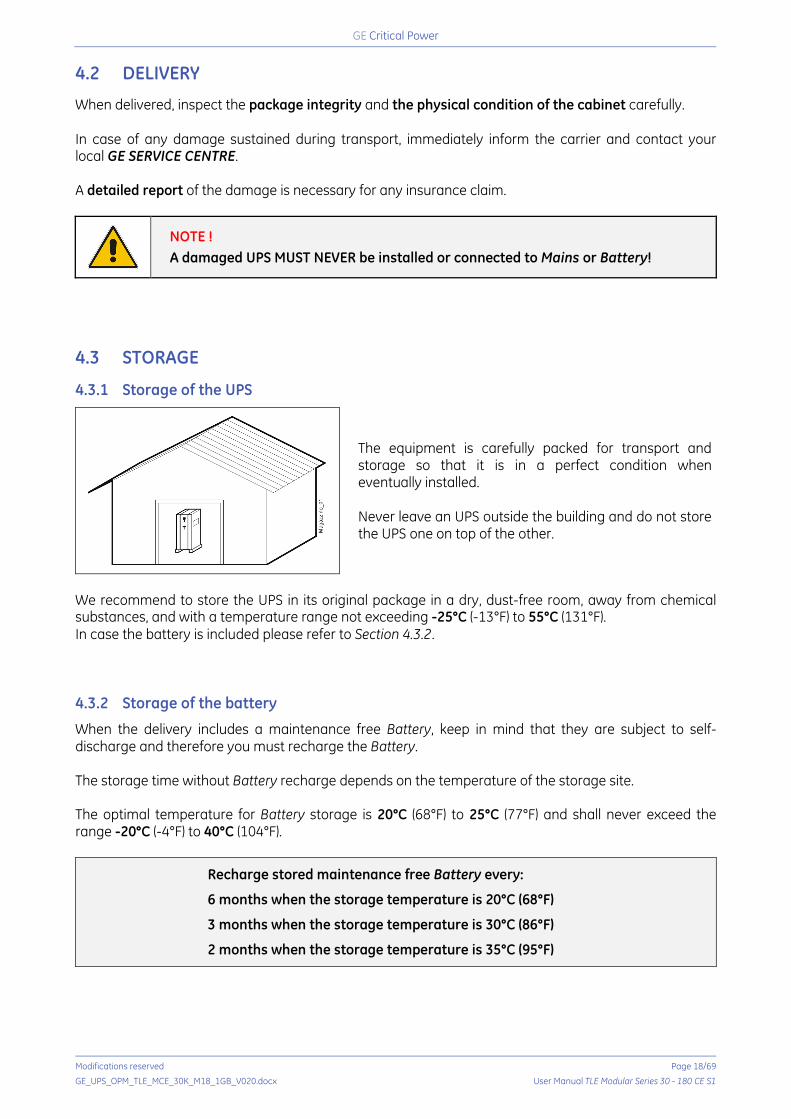
4.3.1 Storage of the UPS
The equipment is carefully packed for transport and storage so that it is in a perfect condition when eventually installed. Never leave an UPS outside the building and do not store the UPS one on top of the other.
We recommend to store the UPS in its original package in a dry, dust-free room, away from chemical substances, and with a temperature range not exceeding -25°C (-13°F) to 55°C (131°F). In case the battery is included please refer to Section 4.3.2. 4.3.2 Storage of the battery
When the delivery includes a maintenance free Battery, keep in mind that they are subject to self-discharge and therefore you must recharge the Battery. The storage time without Battery recharge depends on the temperature of the storage site. The optimal temperature for Battery storage is 20°C (68°F) to 25°C (77°F) and shall never exceed the range -20°C (-4°F) to 40°C (104°F).
Recharge stored maintenance free Battery every:
6 months when the storage temperature is 20°C (68°F)
3 months when the storage temperature is 30°C (86°F)
2 months when the storage temperature is 35°C (95°F)
Critical Power
Modifications reserved Page 19/69
GE_UPS_OPM_TLE_MCE_30K_M18_1GB_V020.docx User Manual TLE Modular Series 30 - 180 CE S1
4.4 PLACE OF INSTALLATION
4.4.1 UPS location
NOTE ! UPS installation and connection must be performed by QUALIFIED SERVICE PERSONNEL only. If optional cabinets and accessories are included with the UPS, please refer to those accompanying manuals for installation and operating instructions. Refer to the “SAFETY RULES” described on Chapter 1.
It is important to have a clean, dust-free environment provided with proper ventilation and air-conditioning to keep the ambient temperature within the specified operating range.
The recommended air inlet temperature is from 20°C (68°F) to 25°C (77°F) (max. 40°C / 104°F).
Check for sufficient floor load capacity before installing the UPS and the Battery. Refer to Section 4.1.1.
For Battery installation follow the local codes and the recommendation of the battery supplier.
NOTE ! Operation at temperatures higher than 25°C (77°F) will reduce battery life. Potential consequences are explained in Section 7.3: read and understand them.
The TLE Modular Series 30 - 180 UPS can radiate radio frequency energy. Although some RFI (Radio Frequency Interference) filtering is inherent to the UPS there is no guarantee that the UPS will not influence sensitive devices such as cameras and monitors that are positioned close by. If interference is expected, the UPS should be moved away from the sensitive equipment.
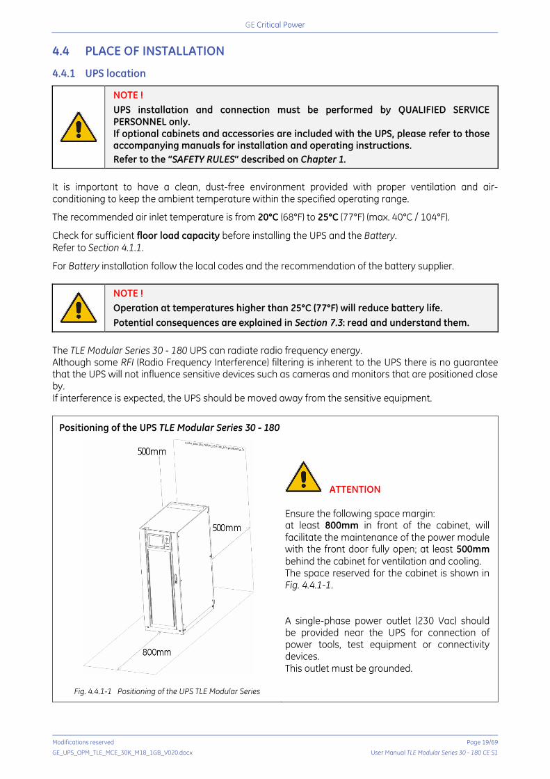
Positioning of the UPS TLE Modular Series 30 - 180
Fig. 4.4.1-1 Positioning of the UPS TLE Modular Series
ATTENTION Ensure the following space margin: at least 800mm in front of the cabinet, will facilitate the maintenance of the power module with the front door fully open; at least 500mm behind the cabinet for ventilation and cooling. The space reserved for the cabinet is shown in Fig. 4.4.1-1. A single-phase power outlet (230 Vac) should be provided near the UPS for connection of power tools, test equipment or connectivity devices. This outlet must be grounded.

Critical Power
Modifications reserved Page 20/69
GE_UPS_OPM_TLE_MCE_30K_M18_1GB_V020.docx User Manual TLE Modular Series 30 - 180 CE S1
4.4.2 Battery location
Batteries require a well-ventilated room with controlled temperature to obtain reliable operation.
The Battery can be installed immediately adjacent to the UPS (left or right side) or remotely from the UPS. If the Battery is installed remotely from the UPS, a wall mounted DC disconnect device must be installed within line-of-site to both the UPS and the Battery.
The optimal room temperature for the Battery is 20°C (68°F) to 25°C (77°F) and shall never exceed the range -20°C (-4°F) to 40°C (104°F).
The life of valve-regulated batteries will be reduced by 50% for each additional 10°C (18°F) in case the Battery ambient temperature is above 25°C (77°F).
The Battery System associated with larger UPS is usually either rack mounted or installed in multiple Battery Cabinets.
Installation and assembly must be made according to the local standards and Battery System manufacturer‘s recommendations.
The additional Battery Circuit Breaker or Battery Fuse Box must be mounted as near as possible to the Battery.
WARNING ! Battery installation and connection must be performed by QUALIFIED PERSONNEL only. Read all safety instructions before proceeding with the installation (see Section 1). Battery discharging and/or charging activities may cause the emission of hydrogen gas; therefore, the room requires proper ventilation and fresh air. Comply with the EN50272-2 standard.
4.4.3 Ventilation and cooling
The heat produced by the UPS is transferred to the environment by its ventilation.
A suitable ventilation or cooling system must be installed to extract the heat from the UPS room.
Air filtering systems could be required when the UPS operates in a dirty environment.
In order to prevent overheating of the UPS, the available air intake flow rate must exceed the total air exhaust flow rate requirement of the UPS system. Contact your Dealer or the nearest GE SERVICE CENTRE for appropriate solutions. The below table indicates the heat dissipation at full Load at PF = 0.9 and charged Battery, up to 1000 m (3280 ft) altitude, for cooling air 25°C (77°F) to 30°C (86°F).
UPS model Losses Cooling air flow
Normal Mode ECO Mode Normal Mode ECO Mode TLE Modular Series 180/30 1.58 kW 0.61 kW 700 m3/h 554 m3/h TLE Modular Series 180/60 3.16 kW 1.22 kW 1228 m3/h 713 m3/h TLE Modular Series 180/90 4.74 kW 1.84 kW 1756 m3/h 871 m3/h TLE Modular Series 180/120 6.32 kW 2.45 kW 2284 m3/h 1030 m3/h TLE Modular Series 180/150 7.89 kW 3.06 kW 2812 m3/h 1188 m3/h TLE Modular Series 180/180 9.47 kW 3.67 kW 3340 m3/h 1346 m3/h
NOTE !
The ventilation and cooling system must be rated as for operation in Normal Mode.
Critical Power
Modifications reserved Page 21/69
GE_UPS_OPM_TLE_MCE_30K_M18_1GB_V020.docx User Manual TLE Modular Series 30 - 180 CE S1
4.5 UNLOADING AND UNPACKING
NOTE ! Be aware of the heavy weight of the UPS, pay attention when moving the UPS cabinet. Take care not to damage the UPS when moving by forklift.
PACKING MATERIAL RECYCLING GE, in compliance with environment protection, uses only environmentally friendly material. UPS packing materials must be recycled in compliance with all applicable regulations.
4.5.1 Moving and unpacking of the UPS cabinet
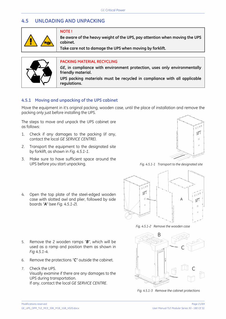
Move the equipment in it’s original packing, wooden case, until the place of installation and remove the packing only just before installing the UPS.
The steps to move and unpack the UPS cabinet are as follows:
1. Check if any damages to the packing (if any, contact the local GE SERVICE CENTRE).
2. Transport the equipment to the designated site by forklift, as shown in Fig. 4.5.1-1.
3. Make sure to have sufficient space around the UPS before you start unpacking.
Fig. 4.5.1-1 Transport to the designated site
4. Open the top plate of the steel-edged wooden case with slotted awl and plier, followed by side boards “A” (see Fig. 4.5.1-2).
Fig. 4.5.1-2 Remove the wooden case
5. Remove the 2 wooden ramps “B”, which will be used as a ramp and position them as shown in Fig 4.5.1-4.
6. Remove the protections “C” outside the cabinet. 7. Check the UPS.
Visually examine if there are any damages to the UPS during transportation. If any, contact the local GE SERVICE CENTRE.
Fig. 4.5.1-3 Remove the cabinet protections
TLES
M_0
30-1
80_U
npac
kagi
ng_0
1-tr
ansp
ort
TLES
M_0
30-1
80_U
PS u
npac
king
_01-
rem
ove
case
A
TLESM_030-180_UPS unpacking_01-remove case
TLES
M_0
30-1
80_U
npac
king
_01-
rem
ove
prot
ectio
ns
B
C
C

Critical Power
Modifications reserved Page 22/69
GE_UPS_OPM_TLE_MCE_30K_M18_1GB_V020.docx User Manual TLE Modular Series 30 - 180 CE S1
8. Remove the 4 angle irons “D”, which are fixing the UPS to the wooden base by unscrewing bolts.
9. Remove the 4 air inlet grids “E”. 10. To put wheels on the UPS cabinet, the 4 feet
“F” must be rotated counter-clockwise until they are off the floor so that the cabinet rests solely on the wheels.
Fig. 4.5.1-4 Remove the 4 angle irons
11. Push the UPS towards the ramp “B” and let it slide down the ramp (see Fig. 4.5.1-5). This has to be done with the utmost care!
Fig. 4.5.1-5 Remove the UPS from the wooden base
12. After positioning the UPS in its final location, fasten the cabinet to the ground by turning the 4 feet “F” in a clockwise direction so that they put pressure on the ground but leaving the wheels in contact with the flooring.
NOTE !
The wheels are designed only for limited movements on the installation site.
To avoid risk of injury do not leave the UPS free to move on wheels!
TLES
M_0
30-1
80_U
PS u
npac
king
_01-
rem
ove
fixin
g
E
D
D
B
EE
F
B
TLES
M_0
30-1
80_U
PS u
npac
king
_01-
mov
e
B

Critical Power
Modifications reserved Page 23/69
GE_UPS_OPM_TLE_MCE_30K_M18_1GB_V020.docx User Manual TLE Modular Series 30 - 180 CE S1
4.5.2 Unpacking power module
The steps to move and unpack the power module are as follows:
1. The packing case must be placed on the platform smoothly, as shown in Fig. 4.5.2-1.
Fig. 4.5.2-1 Place on platform smoothly
2. Cut the plastic packing belt and scotch tape to open the carton (see Fig. 4.5.2-2).
Fig. 4.5.2-2 Disassemble the case
3. Remove the foam cover (see Fig. 4.5.2-3).
Fig. 4.5.2-3 Remove the foam cover
4. Take out the power module and dismantle the packaging materials.
Critical Power
Modifications reserved Page 24/69
GE_UPS_OPM_TLE_MCE_30K_M18_1GB_V020.docx User Manual TLE Modular Series 30 - 180 CE S1
4.6 POSITIONING OF THE TLE MODULAR SERIES 30 - 180
4.6.1 Positioning cabinet
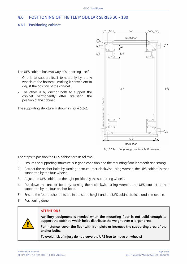
The UPS cabinet has two way of supporting itself:
- One is to support itself temporarily by the 4 wheels at the bottom, making it convenient to adjust the position of the cabinet.
- The other is by anchor bolts to support the cabinet permanently after adjusting the position of the cabinet.
The supporting structure is shown in Fig. 4.6.1-1.
Fig. 4.6.1-1 Supporting structure (bottom view)
The steps to position the UPS cabinet are as follows:
1. Ensure the supporting structure is in good condition and the mounting floor is smooth and strong.
2. Retract the anchor bolts by turning them counter clockwise using wrench, the UPS cabinet is then supported by the four wheels.
3. Adjust the UPS cabinet to the right position by the supporting wheels.
4. Put down the anchor bolts by turning them clockwise using wrench, the UPS cabinet is then supported by the four anchor bolts.
5. Ensure the four anchor bolts are in the same height and the UPS cabinet is fixed and immovable.
6. Positioning done.
ATTENTION !
Auxiliary equipment is needed when the mounting floor is not solid enough to support the cabinet, which helps distribute the weight over a larger area.
For instance, cover the floor with iron plate or increase the supporting area of the anchor bolts.
To avoid risk of injury do not leave the UPS free to move on wheels!

Critical Power
Modifications reserved Page 25/69
GE_UPS_OPM_TLE_MCE_30K_M18_1GB_V020.docx User Manual TLE Modular Series 30 - 180 CE S1
4.6.2 Installing power module
The installation position of power module is shown in Fig. 4.6.2-1. Please install the power modules following the principle of from bottom to top to prevent inclination of the cabinet due to high centre of gravity. The steps of installing power module are as follows: 1. Ensure the UPS cabinet is fixed and no damage to the body and inserting port of the power module. 2. Hold the handler and the body of the power module by two persons. 3. Insert the power module in the installation position and push it into the cabinet smoothly. 4. Fix the power module to the cabinet though the mounting holes on both sides at the front plate of
the power module (see Fig. 4.6.2-1 at right). 5. Installing power module done.
WARNING ! The power module is not provided with a means of stop, do not leave it partially extracted.
Fig. 4.6.2-1 Installing power module
ATTENTION ! Do not place the power module on the floor by rear side with connectors. All installation works for bypass module and power module should be done by 2 persons together, for its heavy weight. RISK OF ELECTRIC SHOCK! UPS slots must be always fitted with power modules or covers. Do not leave slots open. It’s recommended to store covers safely after modules’ installation in case of future needs.

Critical Power
Modifications reserved Page 26/69
GE_UPS_OPM_TLE_MCE_30K_M18_1GB_V020.docx User Manual TLE Modular Series 30 - 180 CE S1
4.7 BATTERY INSTALLATION
Three terminals (positive, neutral and negative) are drawn from the battery unit and connected to UPS system. The neutral line is drawn from the middle of the batteries in series (see Fig. 4.7-1).
Fig. 4.7-1 Battery string wiring diagram
DANGER ! The battery terminal voltage is of more than 400Vdc, please follow the safety instructions to avoid electric shock hazard. Ensure the positive, negative, neutral electrode is correctly connected from the battery unit terminals to the breaker and from the breaker to the UPS system.
4.8 CABLE ENTRY
Both top and bottom cable entry are available. The top and bottom cable entry are shown in Fig. 4.8-1 and Fig. 4.8-2.
Fig. 4.8-1 Top cable entry
Fig. 4.8-2 Bottom cable entry
The correct procedure for top cable entry is as follows: 1. Remove from “Top Entry Cables Cabinet” the top metal cover “A” loosening the 6 screws. 2. Drill the metal cover with appropriate holes for cables entry.
Warning: Do not perform drilling over the top of the UPS to avoid metal filing falling inside the cabinet.
3. The metal cover can accept up to 16 M40 cable glands (see Fig 4.8-1 / “B”) suitable for the rated wiring size: each cable requires a drill and a cable gland.
4. Reinstall on the “Top Entry Cables Cabinet” the top metal cover “A”.
NOTE ! Fix the cables to avoid damage to insulation.
Critical Power
Modifications reserved Page 27/69
GE_UPS_OPM_TLE_MCE_30K_M18_1GB_V020.docx User Manual TLE Modular Series 30 - 180 CE S1
4.9 POWER CABLES
4.9.1 Mains input connection
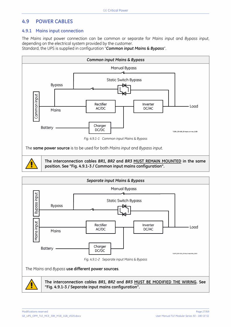
The Mains input power connection can be common or separate for Mains input and Bypass input, depending on the electrical system provided by the customer. Standard, the UPS is supplied in configuration “Common input Mains & Bypass”.
Common input Mains & Bypass
Fig. 4.9.1-1 Common input Mains & Bypass
The same power source is to be used for both Mains input and Bypass input.
The interconnection cables BR1, BR2 and BR3 MUST REMAIN MOUNTED in the same position. See “Fig. 4.9.1-3 / Common input mains configuration”.
Separate input Mains & Bypass
Fig. 4.9.1-2 Separate input Mains & Bypass
The Mains and Bypass use different power sources.
The interconnection cables BR1, BR2 and BR3 MUST BE MODIFIED THE WIRING. See “Fig. 4.9.1-3 / Separate input mains configuration”.
Critical Power
Modifications reserved Page 28/69
GE_UPS_OPM_TLE_MCE_30K_M18_1GB_V020.docx User Manual TLE Modular Series 30 - 180 CE S1
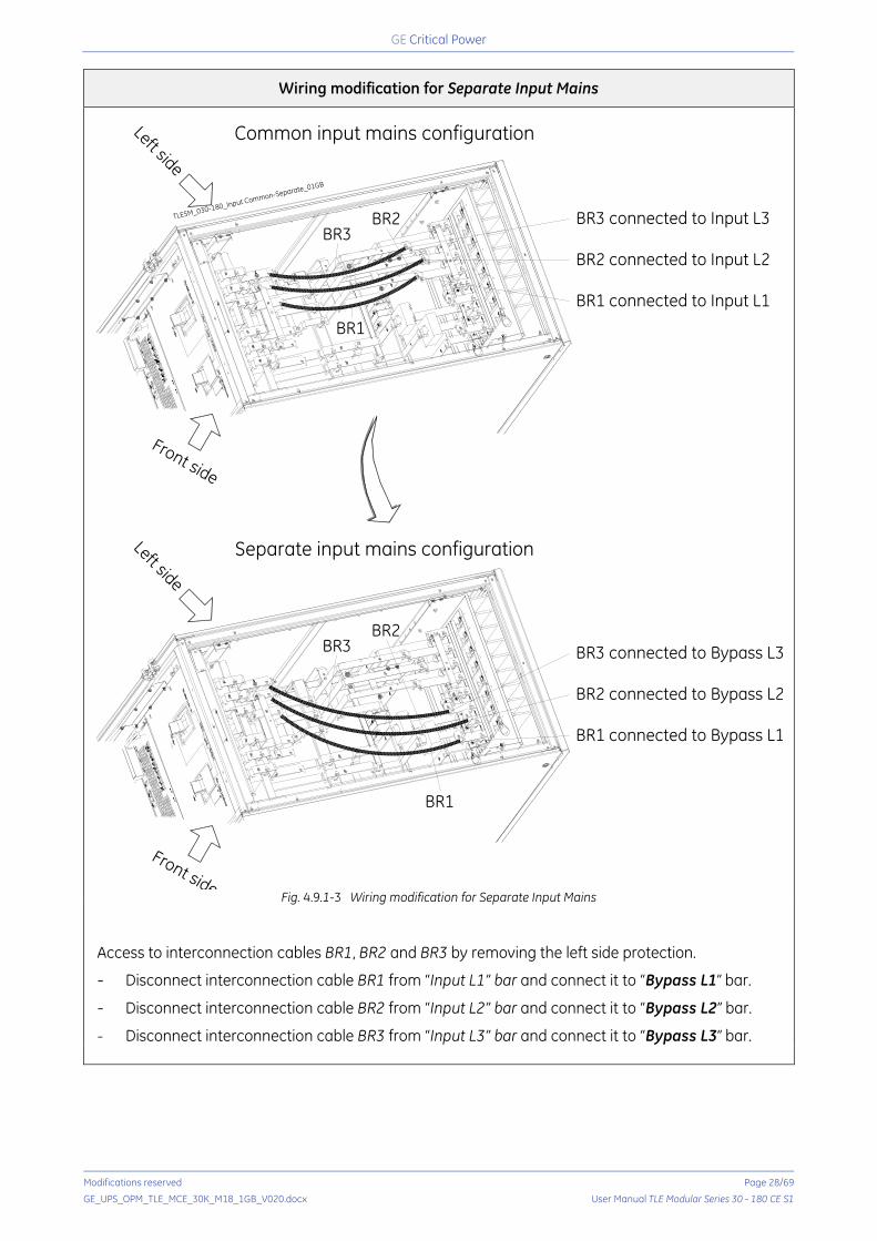
Wiring modification for Separate Input Mains
Fig. 4.9.1-3 Wiring modification for Separate Input Mains
Access to interconnection cables BR1, BR2 and BR3 by removing the left side protection.
Disconnect interconnection cable BR1 from “Input L1” bar and connect it to “Bypass L1” bar.
Disconnect interconnection cable BR2 from “Input L2” bar and connect it to “Bypass L2” bar.
Disconnect interconnection cable BR3 from “Input L3” bar and connect it to “Bypass L3” bar.
TLESM_030-180_Input Common-Separate_01GB
Common input mains configuration
Front side
Left side
BR3 connected to Input L3
BR2 connected to Input L2
BR1 connected to Input L1
BR3 connected to Bypass L3
BR2 connected to Bypass L2
BR1 connected to Bypass L1
Separate input mains configuration
BR1
BR3BR2
BR3BR2
BR1
Left side
Front side
Critical Power
Modifications reserved Page 29/69
GE_UPS_OPM_TLE_MCE_30K_M18_1GB_V020.docx User Manual TLE Modular Series 30 - 180 CE S1
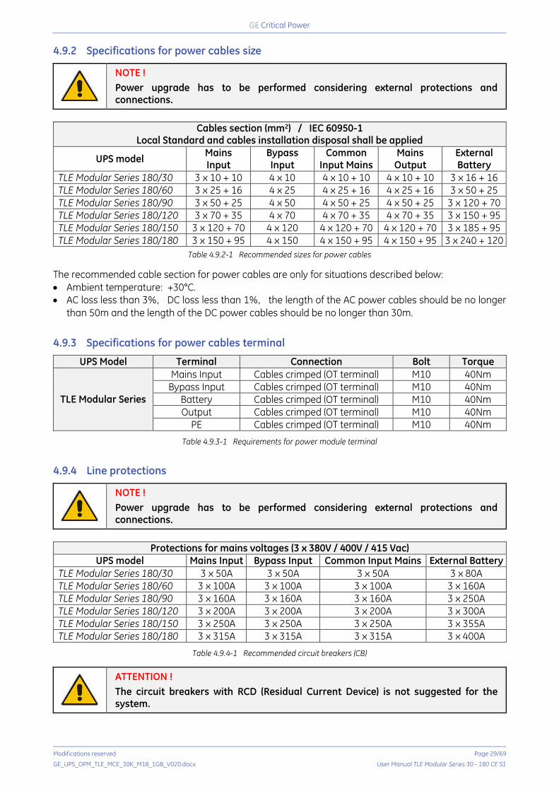
4.9.2 Specifications for power cables size
NOTE ! Power upgrade has to be performed considering external protections and connections.
Cables section (mm2) / IEC 60950-1
Local Standard and cables installation disposal shall be applied
UPS model Mains Input
Bypass Input
Common Input Mains
Mains Output
External Battery
TLE Modular Series 180/30 3 x 10 + 10 4 x 10 4 x 10 + 10 4 x 10 + 10 3 x 16 + 16 TLE Modular Series 180/60 3 x 25 + 16 4 x 25 4 x 25 + 16 4 x 25 + 16 3 x 50 + 25 TLE Modular Series 180/90 3 x 50 + 25 4 x 50 4 x 50 + 25 4 x 50 + 25 3 x 120 + 70 TLE Modular Series 180/120 3 x 70 + 35 4 x 70 4 x 70 + 35 4 x 70 + 35 3 x 150 + 95 TLE Modular Series 180/150 3 x 120 + 70 4 x 120 4 x 120 + 70 4 x 120 + 70 3 x 185 + 95 TLE Modular Series 180/180 3 x 150 + 95 4 x 150 4 x 150 + 95 4 x 150 + 95 3 x 240 + 120
Table 4.9.2-1 Recommended sizes for power cables The recommended cable section for power cables are only for situations described below: • Ambient temperature: +30°C. • AC loss less than 3%, DC loss less than 1%, the length of the AC power cables should be no longer
than 50m and the length of the DC power cables should be no longer than 30m.
4.9.3 Specifications for power cables terminal
UPS Model Terminal Connection Bolt Torque
TLE Modular Series
Mains Input Cables crimped (OT terminal) M10 40Nm Bypass Input Cables crimped (OT terminal) M10 40Nm
Battery Cables crimped (OT terminal) M10 40Nm Output Cables crimped (OT terminal) M10 40Nm
PE Cables crimped (OT terminal) M10 40Nm
Table 4.9.3-1 Requirements for power module terminal
4.9.4 Line protections
NOTE ! Power upgrade has to be performed considering external protections and connections.
Protections for mains voltages (3 x 380V / 400V / 415 Vac)
UPS model Mains Input Bypass Input Common Input Mains External Battery TLE Modular Series 180/30 3 x 50A 3 x 50A 3 x 50A 3 x 80A TLE Modular Series 180/60 3 x 100A 3 x 100A 3 x 100A 3 x 160A TLE Modular Series 180/90 3 x 160A 3 x 160A 3 x 160A 3 x 250A TLE Modular Series 180/120 3 x 200A 3 x 200A 3 x 200A 3 x 300A TLE Modular Series 180/150 3 x 250A 3 x 250A 3 x 250A 3 x 355A TLE Modular Series 180/180 3 x 315A 3 x 315A 3 x 315A 3 x 400A
Table 4.9.4-1 Recommended circuit breakers (CB)
ATTENTION ! The circuit breakers with RCD (Residual Current Device) is not suggested for the system.

Critical Power
Modifications reserved Page 30/69
GE_UPS_OPM_TLE_MCE_30K_M18_1GB_V020.docx User Manual TLE Modular Series 30 - 180 CE S1
4.9.5 Connection of the power cables
ATTENTION ! UPS installation and connection must be performed by QUALIFIED SERVICE PERSONNEL only. Refer to the “SAFETY RULES” described on Chapter 1.
WARNING ! Tighten the connections terminals to enough torque moment, refer to Table 4.9.2-1, and please ensure correct phase rotation. Before connection, ensure the input switch and the power supply are OFF, attach warnings label to warn not to operate by others. The grounding cable and neutral cable must be connected in accordance with local and national codes. Load must be connected to the same ground as that of UPS system.
NOTE ! The UPS is designed for TN system. The input neutral shall be grounded at source and shall never be disconnected. 4 pole breaker shall not be used at the UPS input (see also IEC 60364, IEC 61140, IEC 61557).
The steps of connecting power cables are as follows: 1. Verify that all the external input
distribution switches of the UPS are completely open and the UPS internal static and maintenance bypass switches are OFF. Attach necessary warning signs to these switches to prevent unauthorized operation.
2. Open the back door of the
cabinet, remove the metal cover. The input and output terminal, battery terminal and protective earth terminal are shown in Fig. 4.9.5-1.
3. Connect the protective earth wire
to protective earth terminal (PE).
Fig. 4.9.5-1 Connection terminals
4. Connect the AC input supply cables to the Mains Input terminal and AC output supply cables to the
Output terminal. 5. Connect the Battery cables to the Battery terminal. 6. Check to make sure there is no mistake and re-install all the protective covers.
Critical Power
Modifications reserved Page 31/69
GE_UPS_OPM_TLE_MCE_30K_M18_1GB_V020.docx User Manual TLE Modular Series 30 - 180 CE S1
4.10 CONTROL AND COMMUNICATION CABLES
NOTE !
The cables connected to DRY terminal must be separated from power cables.
Moreover, these cables should be double insulated and be SELV type with a typical 0.5 to 1.5 mm2 cross-section area for a maximum connection length between 25 and 50 meters.
ATTENTION !
The installation of any optional board or firmware/software upgrade to any device must be performed by a GE SERVICE TECHNICIAN only.
Prior to the installation or firmware/software upgrade, connection and cabling of any optional board the UPS must be COMPLETELY POWERED DOWN and all the power sources that will be connected to the optional board must be DE-ENERGIZED.
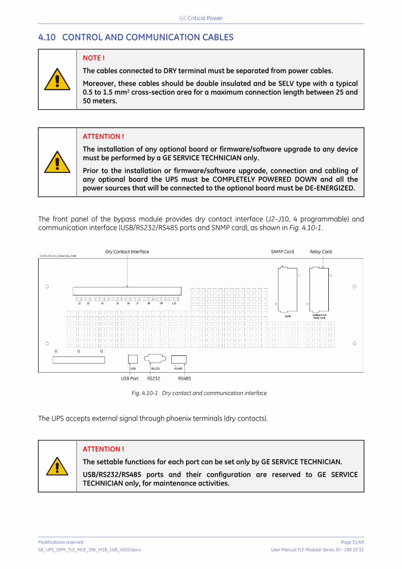
The front panel of the bypass module provides dry contact interface (J2-J10, 4 programmable) and communication interface (USB/RS232/RS485 ports and SNMP card), as shown in Fig. 4.10-1.
Fig. 4.10-1 Dry contact and communication interface The UPS accepts external signal through phoenix terminals (dry contacts).
ATTENTION !
The settable functions for each port can be set only by GE SERVICE TECHNICIAN.
USB/RS232/RS485 ports and their configuration are reserved to GE SERVICE TECHNICIAN only, for maintenance activities.
Critical Power
Modifications reserved Page 32/69
GE_UPS_OPM_TLE_MCE_30K_M18_1GB_V020.docx User Manual TLE Modular Series 30 - 180 CE S1
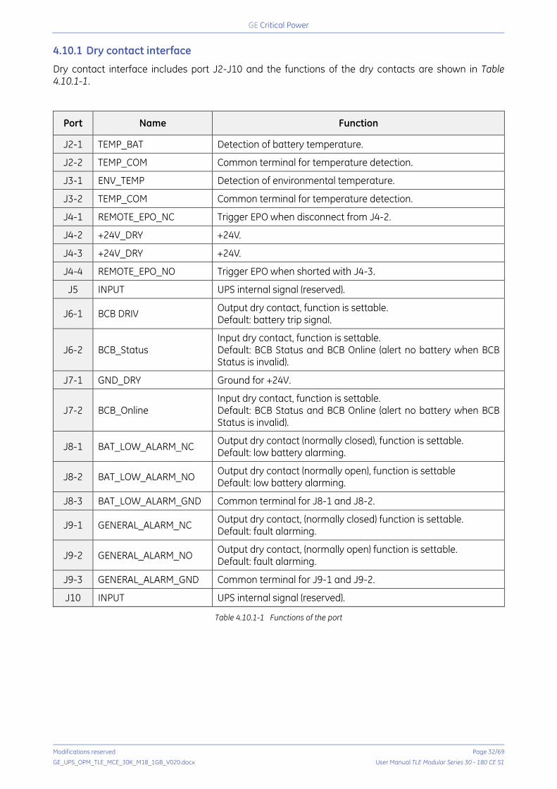
4.10.1 Dry contact interface
Dry contact interface includes port J2-J10 and the functions of the dry contacts are shown in Table 4.10.1-1.
Port Name Function
J2-1 TEMP_BAT Detection of battery temperature.
J2-2 TEMP_COM Common terminal for temperature detection.
J3-1 ENV_TEMP Detection of environmental temperature.
J3-2 TEMP_COM Common terminal for temperature detection.
J4-1 REMOTE_EPO_NC Trigger EPO when disconnect from J4-2.
J4-2 +24V_DRY +24V.
J4-3 +24V_DRY +24V.
J4-4 REMOTE_EPO_NO Trigger EPO when shorted with J4-3.
J5 INPUT UPS internal signal (reserved).
J6-1 BCB DRIV Output dry contact, function is settable. Default: battery trip signal.
J6-2 BCB_Status Input dry contact, function is settable. Default: BCB Status and BCB Online (alert no battery when BCB Status is invalid).
J7-1 GND_DRY Ground for +24V.
J7-2 BCB_Online Input dry contact, function is settable. Default: BCB Status and BCB Online (alert no battery when BCB Status is invalid).
J8-1 BAT_LOW_ALARM_NC Output dry contact (normally closed), function is settable. Default: low battery alarming.
J8-2 BAT_LOW_ALARM_NO Output dry contact (normally open), function is settable Default: low battery alarming.
J8-3 BAT_LOW_ALARM_GND Common terminal for J8-1 and J8-2.
J9-1 GENERAL_ALARM_NC Output dry contact, (normally closed) function is settable. Default: fault alarming.
J9-2 GENERAL_ALARM_NO Output dry contact, (normally open) function is settable. Default: fault alarming.
J9-3 GENERAL_ALARM_GND Common terminal for J9-1 and J9-2.
J10 INPUT UPS internal signal (reserved).
Table 4.10.1-1 Functions of the port
Critical Power
Modifications reserved Page 33/69
GE_UPS_OPM_TLE_MCE_30K_M18_1GB_V020.docx User Manual TLE Modular Series 30 - 180 CE S1
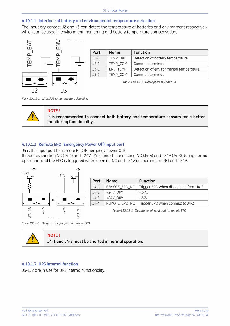
4.10.1.1 Interface of battery and environmental temperature detection The input dry contact J2 and J3 can detect the temperature of batteries and environment respectively, which can be used in environment monitoring and battery temperature compensation.
Port Name Function J2-1 TEMP_BAT Detection of battery temperature. J2-2 TEMP_COM Common terminal. J3-1 ENV_TEMP Detection of environmental temperature. J3-2 TEMP_COM Common terminal.
Table 4.10.1.1-1 Description of J2 and J3
Fig. 4.10.1.1-1 J2 and J3 for temperature detecting
NOTE ! It is recommended to connect both battery and temperature sensors for a better monitoring functionality.
4.10.1.2 Remote EPO (Emergency Power Off) input port J4 is the input port for remote EPO (Emergency Power Off). It requires shorting NC (J4-1) and +24V (J4-2) and disconnecting NO (J4-4) and +24V (J4-3) during normal operation, and the EPO is triggered when opening NC and +24V or shorting the NO and +24V.
Port Name Function J4-1 REMOTE_EPO_NC Trigger EPO when disconnect from J4-2. J4-2 +24V_DRY +24V. J4-3 +24V_DRY +24V. J4-4 REMOTE_EPO_NO Trigger EPO when connect to J4-3.
Table 4.10.1.2-1 Description of input port for remote EPO
Fig. 4.10.1.2-1 Diagram of input port for remote EPO
NOTE ! J4-1 and J4-2 must be shorted in normal operation.
4.10.1.3 UPS internal function J5-1, 2 are in use for UPS internal functionality.
Critical Power
Modifications reserved Page 34/69
GE_UPS_OPM_TLE_MCE_30K_M18_1GB_V020.docx User Manual TLE Modular Series 30 - 180 CE S1
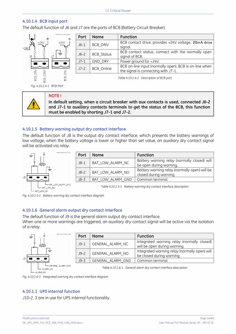
4.10.1.4 BCB input port The default function of J6 and J7 are the ports of BCB (Battery Circuit Breaker).
Port Name Function
J6-1 BCB_DRIV BCB contact drive, provides +24V voltage,20mA drive signal.
J6-2 BCB_Status BCB contact status, connect with the normally open signal of BCB.
J7-1 GND_DRY Power ground for +24V.
J7-2 BCB_Online BCB on-line input (normally open), BCB is on-line when the signal is connecting with J7-1.
Table 4.10.1.4-1 Description of BCB port
Fig. 4.10.1.4-1 BCB Port
NOTE ! In default setting, when a circuit breaker with aux contacts is used, connected J6-2 and J7-1 to auxiliary contacts terminals to get the status of the BCB, this function must be enabled by shorting J7-1 and J7-2.
4.10.1.5 Battery warning output dry contact interface The default function of J8 is the output dry contact interface, which presents the battery warnings of low voltage, when the battery voltage is lower or higher than set value, an auxiliary dry contact signal will be activated via relay.
Port Name Function
J8-1 BAT_LOW_ALARM_NC Battery warning relay (normally closed) will be open during warning.
J8-2 BAT_LOW_ALARM_NO Battery warning relay (normally open) will be closed during warning.
J8-3 BAT_LOW_ALARM_GND Common terminal.
Table 4.10.1.5-1 Battery warning dry contact interface description
Fig. 4.10.1.5-1 Battery warning dry contact interface diagram
4.10.1.6 General alarm output dry contact interface The default function of J9 is the general alarm output dry contact interface. When one or more warnings are triggered, an auxiliary dry contact signal will be active via the isolation of a relay.
Port Name Function
J9-1 GENERAL_ALARM_NC Integrated warning relay (normally closed) will be open during warning.
J9-2 GENERAL_ALARM_NO Integrated warning relay (normally open) will be closed during warning.
J9-3 GENERAL_ALARM_GND Common terminal.
Table 4.10.1.6-1 General alarm dry contact interface description
Fig. 4.10.1.6-1 Integrated warning dry contact interface diagram
4.10.1.1 UPS internal function J10-2, 3 are in use for UPS internal functionality.
Critical Power
Modifications reserved Page 35/69
GE_UPS_OPM_TLE_MCE_30K_M18_1GB_V020.docx User Manual TLE Modular Series 30 - 180 CE S1
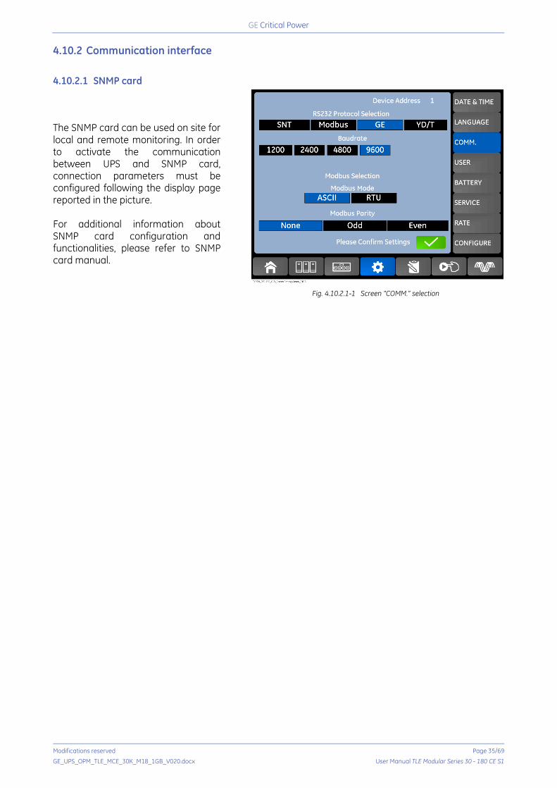
4.10.2 Communication interface
4.10.2.1 SNMP card
The SNMP card can be used on site for local and remote monitoring. In order to activate the communication between UPS and SNMP card, connection parameters must be configured following the display page reported in the picture. For additional information about SNMP card configuration and functionalities, please refer to SNMP card manual.
Fig. 4.10.2.1-1 Screen “COMM.” selection
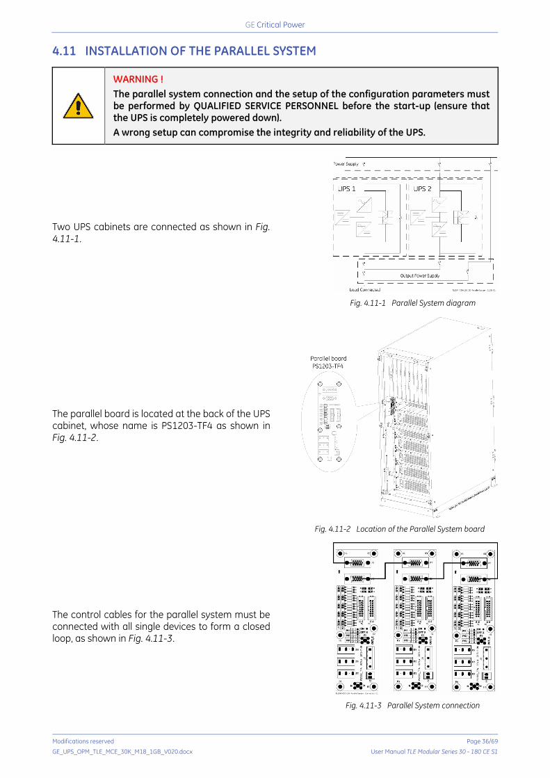
Critical Power
Modifications reserved Page 36/69
GE_UPS_OPM_TLE_MCE_30K_M18_1GB_V020.docx User Manual TLE Modular Series 30 - 180 CE S1
4.11 INSTALLATION OF THE PARALLEL SYSTEM
WARNING ! The parallel system connection and the setup of the configuration parameters must be performed by QUALIFIED SERVICE PERSONNEL before the start-up (ensure that the UPS is completely powered down). A wrong setup can compromise the integrity and reliability of the UPS.
Two UPS cabinets are connected as shown in Fig. 4.11-1.
Fig. 4.11-1 Parallel System diagram
The parallel board is located at the back of the UPS cabinet, whose name is PS1203-TF4 as shown in Fig. 4.11-2.
Fig. 4.11-2 Location of the Parallel System board
The control cables for the parallel system must be connected with all single devices to form a closed loop, as shown in Fig. 4.11-3.
Fig. 4.11-3 Parallel System connection
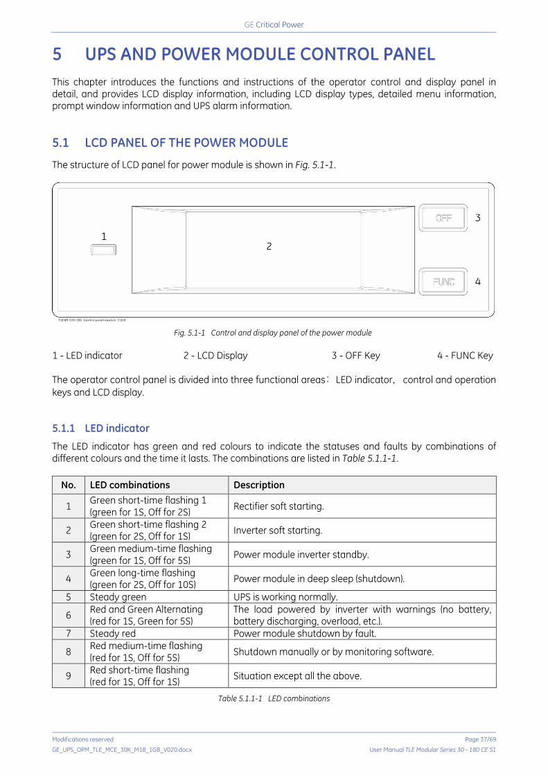
Critical Power
Modifications reserved Page 37/69
GE_UPS_OPM_TLE_MCE_30K_M18_1GB_V020.docx User Manual TLE Modular Series 30 - 180 CE S1
5 UPS AND POWER MODULE CONTROL PANEL This chapter introduces the functions and instructions of the operator control and display panel in detail, and provides LCD display information, including LCD display types, detailed menu information, prompt window information and UPS alarm information. 5.1 LCD PANEL OF THE POWER MODULE
The structure of LCD panel for power module is shown in Fig. 5.1-1.
Fig. 5.1-1 Control and display panel of the power module
1 - LED indicator 2 - LCD Display 3 - OFF Key 4 - FUNC Key The operator control panel is divided into three functional areas: LED indicator, control and operation keys and LCD display. 5.1.1 LED indicator
The LED indicator has green and red colours to indicate the statuses and faults by combinations of different colours and the time it lasts. The combinations are listed in Table 5.1.1-1.
No. LED combinations Description
1 Green short-time flashing 1 (green for 1S, Off for 2S) Rectifier soft starting.
2 Green short-time flashing 2 (green for 2S, Off for 1S) Inverter soft starting.
3 Green medium-time flashing (green for 1S, Off for 5S) Power module inverter standby.
4 Green long-time flashing (green for 2S, Off for 10S) Power module in deep sleep (shutdown).
5 Steady green UPS is working normally.
6 Red and Green Alternating (red for 1S, Green for 5S)
The load powered by inverter with warnings (no battery, battery discharging, overload, etc.).
7 Steady red Power module shutdown by fault.
8 Red medium-time flashing (red for 1S, Off for 5S) Shutdown manually or by monitoring software.
9 Red short-time flashing (red for 1S, Off for 1S) Situation except all the above.
Table 5.1.1-1 LED combinations

Critical Power
Modifications reserved Page 38/69
GE_UPS_OPM_TLE_MCE_30K_M18_1GB_V020.docx User Manual TLE Modular Series 30 - 180 CE S1
5.1.2 Control and operation keys
The control and operation keys include “FUNC” key and “OFF” key that have different functions: a. “FUNC” key: cycle through the measurements on the display. b. “OFF” key: shut down the module, as the following procedures:
1) The “OFF” key is disabled by default and must be enabled via the display:
-> Menu Operate -> Press .
2) Press the “OFF” key for 3 seconds, the power module will be excluded from the system. 5.1.3 LCD Display
LCD is for displaying the information for the power module and its structure is shown in Fig. 5.1.3-1.
1-2
3-1
4-1
1-1 2-1 2-2
2-3 2-4 1-3
3-2
3-3
4-2
4-3
Fig. 5.1.3-1 LCD display for power module
1 Select triangle 2 Energy bar 3 Digit Display Area 4 Unit
Users can browse the information of each power module by pressing the “FUNC” key to turn the pages.
Select triangle of highlighted Input information is presented in the Digit Displays Area: 3-phase voltage and 3-phase current.
Select triangle of highlighted
Output information is presented in the Digit Displays Area: 3-phase voltage, 3-phase current and the 3-phase load percentage.
Select triangle of highlighted
Battery information is presented in the Digit Displays Area: battery positive voltage, battery positive charge/discharge current and bus positive voltage.
Select triangle of highlighted
Battery information is presented in the Digit Displays Area: battery negative voltage, battery negative charge/discharge current and bus negative voltage.
highlighted Fault and warning codes are shown in Digit Displays Area. The meanings of the codes are listed in Table 5.1.3-1.
flashing Indicating a fault occurs.
Energy bar of
Flashing: rectifier soft start. Highlighted: the rectifier is working normally. Off: other situation.

Critical Power
Modifications reserved Page 39/69
GE_UPS_OPM_TLE_MCE_30K_M18_1GB_V020.docx User Manual TLE Modular Series 30 - 180 CE S1
Energy bar of
Flashing: inverter soft start. Highlighted: load on inverter. Off: other situation.
Energy bar of
Flashing: low battery voltage. Highlighted: charging normally. Off: battery not connected.
Energy bar of
Lightened: discharging mode. Off: battery not connected or charging.
Unit: Voltage (V), Current (A), Percentage (%). The reading selected on one power module will be shown on all other power modules within 2 seconds.
Codes Description Codes Description
16 Mains voltage abnormal 67 Battery polarity reversed
18 Bypass phase sequence fault 69 Inverter protected
20 Bypass voltage abnormal 71 Neutral disconnected
28 Bypass Over-track frequency 74 Module shut down manually
30 Transfer times (from inverter to bypass) in 1 hour exceed the limit. 81 Battery or charger fail
32 Output shorted 83 Lost N+X redundancy
34 EOD (End Discharge Voltage) of battery 85 EOD (End Discharge Voltage) system
inhibited
38 Battery test fail 93 Inverter IO CAN fail
41 Battery maintenance fail 95 Data CAN fail
47 Rectifier fail 97 Power share fail
49 Inverter fail 109 Inverter bridge open
51 Rectifier over temperature 111 Temperature difference over limit
53 Fan fail 113 Input current unbalanced
55 Output overload 115 DC bus over voltage
57 Output overload time out 117 Rectifier soft start fail
59 Inverter over temperature 119 Relay open
61 UPS inverter Inhibited 121 Relay shorted
65 Low battery 127 Transfer to inverter manually
Table 5.1.3-1 Faults and warnings codes

Critical Power
Modifications reserved Page 40/69
GE_UPS_OPM_TLE_MCE_30K_M18_1GB_V020.docx User Manual TLE Modular Series 30 - 180 CE S1
5.2 UPS CONTROL PANEL
The structure of operator control and display panel for cabinet is shown in Fig. 5.2-1.
Fig. 5.2-1 Control and display panel for cabinet
1 LCD touch screen 7 Inverter indicator 2 EPO button 8 Output indicator 3 Audible Alarm (Buzzer) 9 Battery indicator 4 Status indicator 10 Bypass transfer 5 Bypass indicator 11 Inverter transfer 6 Rectifier indicator 12 Mute The LCD panel for cabinet is divided into three functional areas:
• LED indicator.
• Control and operation keys.
• LCD touch screen.
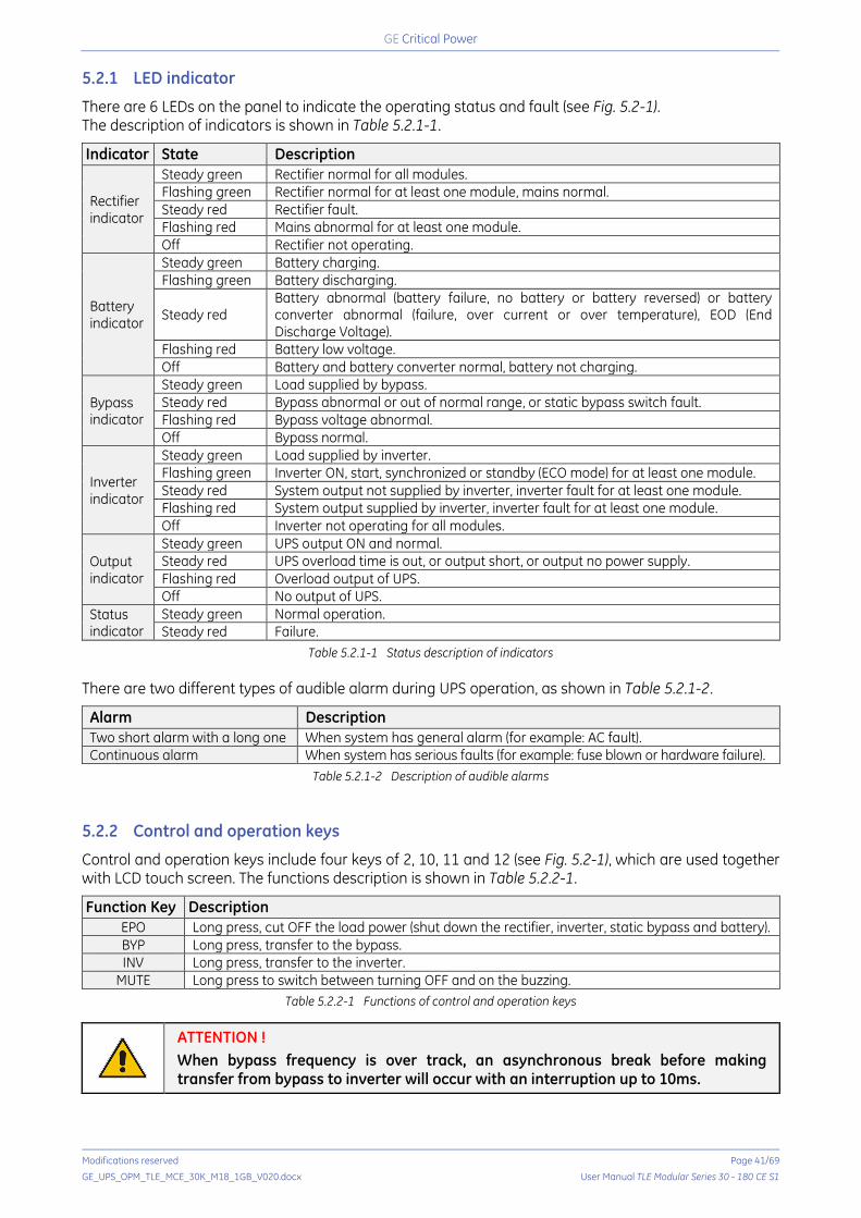
Critical Power
Modifications reserved Page 41/69
GE_UPS_OPM_TLE_MCE_30K_M18_1GB_V020.docx User Manual TLE Modular Series 30 - 180 CE S1
5.2.1 LED indicator
There are 6 LEDs on the panel to indicate the operating status and fault (see Fig. 5.2-1). The description of indicators is shown in Table 5.2.1-1.
Indicator State Description
Rectifier indicator
Steady green Rectifier normal for all modules. Flashing green Rectifier normal for at least one module, mains normal. Steady red Rectifier fault. Flashing red Mains abnormal for at least one module. Off Rectifier not operating.
Battery indicator
Steady green Battery charging. Flashing green Battery discharging.
Steady red Battery abnormal (battery failure, no battery or battery reversed) or battery converter abnormal (failure, over current or over temperature), EOD (End Discharge Voltage).
Flashing red Battery low voltage. Off Battery and battery converter normal, battery not charging.
Bypass indicator
Steady green Load supplied by bypass. Steady red Bypass abnormal or out of normal range, or static bypass switch fault. Flashing red Bypass voltage abnormal. Off Bypass normal.
Inverter indicator
Steady green Load supplied by inverter. Flashing green Inverter ON, start, synchronized or standby (ECO mode) for at least one module. Steady red System output not supplied by inverter, inverter fault for at least one module. Flashing red System output supplied by inverter, inverter fault for at least one module. Off Inverter not operating for all modules.
Output indicator
Steady green UPS output ON and normal. Steady red UPS overload time is out, or output short, or output no power supply. Flashing red Overload output of UPS. Off No output of UPS.
Status indicator
Steady green Normal operation. Steady red Failure.
Table 5.2.1-1 Status description of indicators There are two different types of audible alarm during UPS operation, as shown in Table 5.2.1-2.
Alarm Description Two short alarm with a long one When system has general alarm (for example: AC fault). Continuous alarm When system has serious faults (for example: fuse blown or hardware failure).
Table 5.2.1-2 Description of audible alarms 5.2.2 Control and operation keys
Control and operation keys include four keys of 2, 10, 11 and 12 (see Fig. 5.2-1), which are used together with LCD touch screen. The functions description is shown in Table 5.2.2-1.
Function Key Description EPO Long press, cut OFF the load power (shut down the rectifier, inverter, static bypass and battery). BYP Long press, transfer to the bypass. INV Long press, transfer to the inverter.
MUTE Long press to switch between turning OFF and on the buzzing. Table 5.2.2-1 Functions of control and operation keys
ATTENTION ! When bypass frequency is over track, an asynchronous break before making transfer from bypass to inverter will occur with an interruption up to 10ms.
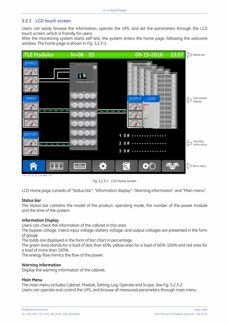
Critical Power
Modifications reserved Page 42/69
GE_UPS_OPM_TLE_MCE_30K_M18_1GB_V020.docx User Manual TLE Modular Series 30 - 180 CE S1
5.2.3 LCD touch screen
Users can easily browse the information, operate the UPS, and set the parameters through the LCD touch screen, which is friendly for users. After the monitoring system starts self-test, the system enters the home page, following the welcome window. The home page is shown in Fig. 5.2.3-1.
Fig. 5.2.3-1 LCD Home screen LCD Home page consists of “Status bar”, “Information display”, “Warning information” and “Main menu”. Status bar The Status bar contains the model of the product, operating mode, the number of the power module and the time of the system. Information Display Users can check the information of the cabinet in this area. The bypass voltage, mains input voltage, battery voltage, and output voltages are presented in the form of gauge. The loads are displayed in the form of bar chart in percentage. The green area stands for a load of less than 60%, yellow area for a load of 60%-100% and red area for a load of more than 100%. The energy flow mimics the flow of the power. Warning Information Display the warning information of the cabinet. Main Menu The main menu includes Cabinet, Module, Setting, Log, Operate and Scope. See Fig. 5.2.3-2. Users can operate and control the UPS, and browse all measured parameters through main menu.

Critical Power
Modifications reserved Page 43/69
GE_UPS_OPM_TLE_MCE_30K_M18_1GB_V020.docx User Manual TLE Modular Series 30 - 180 CE S1
The structure of the main menu tree is shown in Fig. 5.2.3-2.
Fig. 5.2.3-2 Structure of the main menu tree
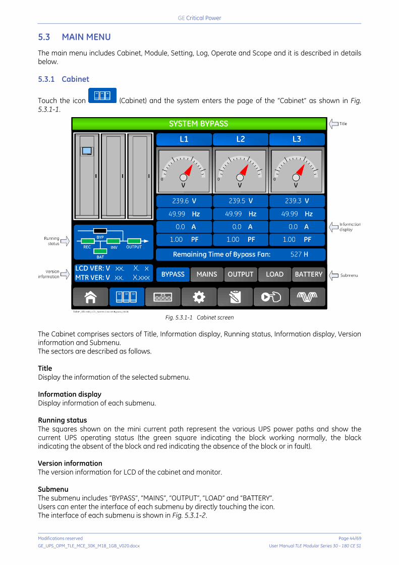
Critical Power
Modifications reserved Page 44/69
GE_UPS_OPM_TLE_MCE_30K_M18_1GB_V020.docx User Manual TLE Modular Series 30 - 180 CE S1
5.3 MAIN MENU
The main menu includes Cabinet, Module, Setting, Log, Operate and Scope and it is described in details below. 5.3.1 Cabinet
Touch the icon (Cabinet) and the system enters the page of the “Cabinet” as shown in Fig. 5.3.1-1.
Fig. 5.3.1-1 Cabinet screen
The Cabinet comprises sectors of Title, Information display, Running status, Information display, Version information and Submenu. The sectors are described as follows. Title Display the information of the selected submenu. Information display Display information of each submenu. Running status The squares shown on the mini current path represent the various UPS power paths and show the current UPS operating status (the green square indicating the block working normally, the black indicating the absent of the block and red indicating the absence of the block or in fault). Version information The version information for LCD of the cabinet and monitor. Submenu The submenu includes “BYPASS”, “MAINS”, “OUTPUT”, “LOAD” and “BATTERY”. Users can enter the interface of each submenu by directly touching the icon. The interface of each submenu is shown in Fig. 5.3.1-2.

Critical Power
Modifications reserved Page 45/69
GE_UPS_OPM_TLE_MCE_30K_M18_1GB_V020.docx User Manual TLE Modular Series 30 - 180 CE S1
a) Interface of Cabinet Mains b) Interface of Cabinet Output
c) Interface of Cabinet Load d) Interface of Cabinet Battery
Fig. 5.3.1-2 Submenu interface of Cabinet The submenu of Cabinet is described in details below in Table 5.3.1-1. Submenu Contents Meaning Submenu Contents Meaning
MAINS
V Phase voltage
LOAD
kVA Sout: Apparent power A Phase current kW Pout: Active power
Hz Input frequency kVar Qout: Reactive power PF Power factor % Load (the percentage of the UPS load)
BYPASS
V Phase voltage
BATTERY
V Battery positive/negative Voltage
A Phase current A Battery positive/negative Current
Hz Bypass frequency Charge level (%) Battery charge level
PF Power factor
OUTPUT
V Phase voltage Autonomy (Min) Autonomy battery backup time
A Phase current Battery (°C) Battery temperature
Hz Output frequency Ambient (°C) Environmental temperature
PF Power factor Total Work T Total work time
Total Discharge T Total discharging time
Table 5.3.1-1 Description of each submenu of Cabinet

Critical Power
Modifications reserved Page 46/69
GE_UPS_OPM_TLE_MCE_30K_M18_1GB_V020.docx User Manual TLE Modular Series 30 - 180 CE S1
5.3.2 Module
Touch the icon (Module) and the system enters the page of the “Module” as shown in Fig. 5.3.2-1.
Fig. 5.3.2-1 Module screen The module comprises sectors of Title, Information display, Power module information, Version information and Submenu. The sectors are described as follows. Title Present the title of submenu of the selected power module. Information display Display information of each submenu. Power module information The users can choose the power module to browse the information in the “Information display” sector. Colours of the square on the mimic current path represent the various power module paths and show the current operating status. The green square indicating the module working normally. The black indicating module is invalid. The red indicating the absence of the module or in fault. Take the 1#module for example. It indicates that UPS is in Normal mode and the rectifier and inverter are working normally. The battery is not connected. Version information The version information for rectifier and inverter of the selected module.

Critical Power
Modifications reserved Page 47/69
GE_UPS_OPM_TLE_MCE_30K_M18_1GB_V020.docx User Manual TLE Modular Series 30 - 180 CE S1
Submenu The submenu includes “INPUT”, “OUTPUT”, “LOAD”, “INFO.” and “S-CODE”. Users can enter the interface of each submenu by directly touching the icon. The interface of each submenu is shown in Fig. 5.3.2-2.
a) Interface of Module Output b) Interface of Module Load
c) Interface of Module Information d) Interface of Module S-Code
Fig. 5.3.2-2 Submenu interface of Module
The submenus of Module are described below in details in Table 5.3.2-1.
Submenu Contents Meaning
INPUT
V Input phase voltage of selected module. A Input phase current of selected module. Hz Input frequency of selected module. PF Input power factor of selected module.
OUTPUT
V Output phase voltage of selected module. A Output phase current of selected module. Hz Output frequency of selected module. PF Output power factor of selected module.
LOAD
V Load voltage of selected module. % Load (the percentage of the power module selected). KW Pout: active power. KVA Sout: apparent power.
INFO. (Information)
BATT+ (V) Battery voltage (positive). BATT- (V) Battery voltage (negative). BUS (V) Bus voltage (positive & negative). Charger (V) Charger voltage (positive & negative). Fan Remain T Fan’s remaining time of the selected power module before maintenance. Cap Remain T Capacitor’s remaining time of the selected power module before maintenance. REC IGBT Temperature Temperature of Rectifier IGBT phase L1, L2 and L3. INV IGBT Temperature Temperature of Inverter IGBT phase L1, L2 and L3. Inlet Temperature (°C) Inlet temperature of the selected power module. Outlet Temperature (°C) Outlet temperature of the selected power module.
S-CODE Fault Code For the maintenance personnel. Table 5.3.2-1 Description of each submenu of Module
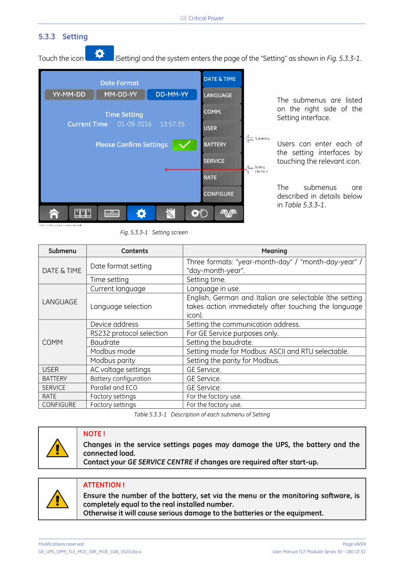
Critical Power
Modifications reserved Page 48/69
GE_UPS_OPM_TLE_MCE_30K_M18_1GB_V020.docx User Manual TLE Modular Series 30 - 180 CE S1
5.3.3 Setting
Touch the icon (Setting) and the system enters the page of the “Setting” as shown in Fig. 5.3.3-1.
Fig. 5.3.3-1 Setting screen
The submenus are listed on the right side of the Setting interface. Users can enter each of the setting interfaces by touching the relevant icon. The submenus are described in details below in Table 5.3.3-1.
Submenu Contents Meaning
DATE & TIME Date format setting Three formats: “year-month-day” / “month-day-year” / “day-month-year”.
Time setting Setting time.
LANGUAGE
Current language Language in use.
Language selection English, German and Italian are selectable (the setting takes action immediately after touching the language icon).
COMM
Device address Setting the communication address. RS232 protocol selection For GE Service purposes only. Baudrate Setting the baudrate. Modbus mode Setting mode for Modbus: ASCII and RTU selectable. Modbus parity Setting the parity for Modbus.
USER AC voltage settings GE Service. BATTERY Battery configuration GE Service. SERVICE Parallel and ECO GE Service. RATE Factory settings For the factory use. CONFIGURE Factory settings For the factory use.
Table 5.3.3-1 Description of each submenu of Setting
NOTE ! Changes in the service settings pages may damage the UPS, the battery and the connected load. Contact your GE SERVICE CENTRE if changes are required after start-up.
ATTENTION ! Ensure the number of the battery, set via the menu or the monitoring software, is completely equal to the real installed number. Otherwise it will cause serious damage to the batteries or the equipment.
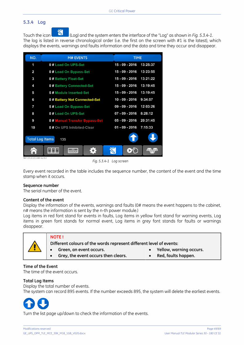
Critical Power
Modifications reserved Page 49/69
GE_UPS_OPM_TLE_MCE_30K_M18_1GB_V020.docx User Manual TLE Modular Series 30 - 180 CE S1
5.3.4 Log
Touch the icon (Log) and the system enters the interface of the “Log” as shown in Fig. 5.3.4-1. The log is listed in reverse chronological order (i.e. the first on the screen with #1 is the latest), which displays the events, warnings and faults information and the data and time they occur and disappear.
Fig. 5.3.4-1 Log screen
Every event recorded in the table includes the sequence number, the content of the event and the time stamp when it occurs. Sequence number The serial number of the event. Content of the event Display the information of the events, warnings and faults (0# means the event happens to the cabinet, n# means the information is sent by the n-th power module.) Log items in red font stand for events in faults, Log items in yellow font stand for warning events, Log items in green font stands for normal event, Log items in grey font stands for faults or warnings disappear.
NOTE ! Different colours of the words represent different level of events: • Green, an event occurs. • Grey, the event occurs then clears.
• Yellow, warning occurs. • Red, faults happen.
Time of the Event The time of the event occurs. Total Log Items Display the total number of events. The system can record 895 events. If the number exceeds 895, the system will delete the earliest events.
Turn the list page up/down to check the information of the events.

Critical Power
Modifications reserved Page 50/69
GE_UPS_OPM_TLE_MCE_30K_M18_1GB_V020.docx User Manual TLE Modular Series 30 - 180 CE S1
5.3.5 Operate
Touch the icon (Operate) and the system enters the page of the “Operate” as shown in Fig. 5.3.5-1.
Fig. 5.3.5-1 Operate screen
The “Operate” menu includes FUNCTION BUTTON and TEST COMMAND. The contents are described in details below. FUNCTION BUTTON Esc Mute (Clear/Restore Buzzing)
Mute or Restore buzzing of the system by touching the icon or . Fault Clear
Clear the faults by touching the icon . For GE Service purposes only. Transfer to and ESC Bypass
Transfer to Bypass mode or cancel this command by touching the icon or . For GE Service purposes only.
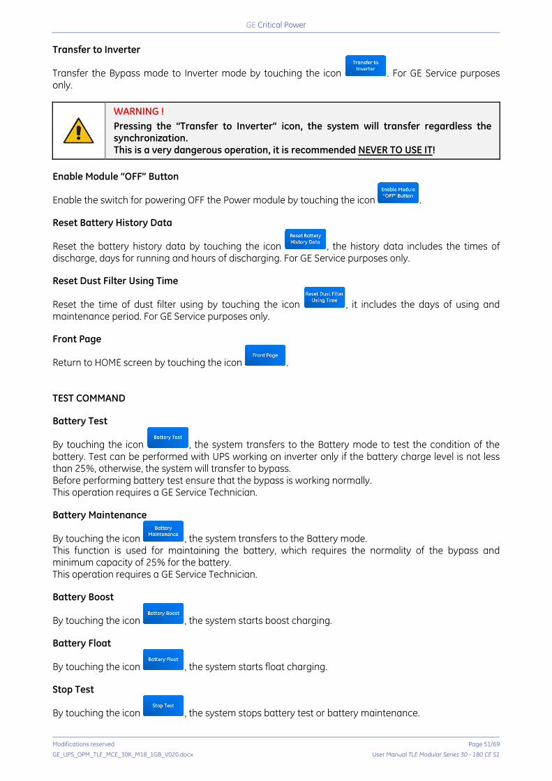
Critical Power
Modifications reserved Page 51/69
GE_UPS_OPM_TLE_MCE_30K_M18_1GB_V020.docx User Manual TLE Modular Series 30 - 180 CE S1
Transfer to Inverter
Transfer the Bypass mode to Inverter mode by touching the icon . For GE Service purposes only.
WARNING ! Pressing the “Transfer to Inverter” icon, the system will transfer regardless the synchronization. This is a very dangerous operation, it is recommended NEVER TO USE IT!
Enable Module “OFF” Button
Enable the switch for powering OFF the Power module by touching the icon . Reset Battery History Data
Reset the battery history data by touching the icon , the history data includes the times of discharge, days for running and hours of discharging. For GE Service purposes only. Reset Dust Filter Using Time
Reset the time of dust filter using by touching the icon , it includes the days of using and maintenance period. For GE Service purposes only. Front Page
Return to HOME screen by touching the icon . TEST COMMAND Battery Test
By touching the icon , the system transfers to the Battery mode to test the condition of the battery. Test can be performed with UPS working on inverter only if the battery charge level is not less than 25%, otherwise, the system will transfer to bypass. Before performing battery test ensure that the bypass is working normally. This operation requires a GE Service Technician. Battery Maintenance
By touching the icon , the system transfers to the Battery mode. This function is used for maintaining the battery, which requires the normality of the bypass and minimum capacity of 25% for the battery. This operation requires a GE Service Technician. Battery Boost
By touching the icon , the system starts boost charging. Battery Float
By touching the icon , the system starts float charging. Stop Test
By touching the icon , the system stops battery test or battery maintenance.
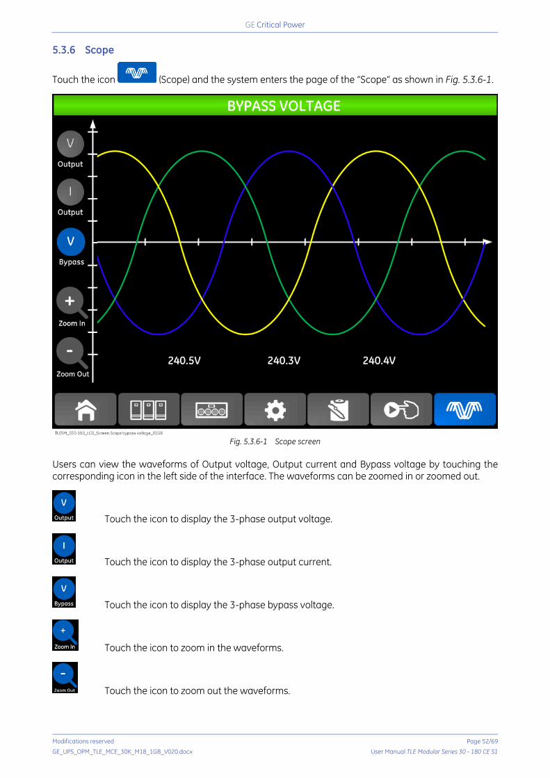
Critical Power
Modifications reserved Page 52/69
GE_UPS_OPM_TLE_MCE_30K_M18_1GB_V020.docx User Manual TLE Modular Series 30 - 180 CE S1
5.3.6 Scope
Touch the icon (Scope) and the system enters the page of the “Scope” as shown in Fig. 5.3.6-1.
Fig. 5.3.6-1 Scope screen Users can view the waveforms of Output voltage, Output current and Bypass voltage by touching the corresponding icon in the left side of the interface. The waveforms can be zoomed in or zoomed out.
Touch the icon to display the 3-phase output voltage.
Touch the icon to display the 3-phase output current.
Touch the icon to display the 3-phase bypass voltage.
Touch the icon to zoom in the waveforms.
Touch the icon to zoom out the waveforms.

Critical Power
Modifications reserved Page 53/69
GE_UPS_OPM_TLE_MCE_30K_M18_1GB_V020.docx User Manual TLE Modular Series 30 - 180 CE S1
6 OPERATIONS 6.1 UPS START-UP
6.1.1 Start in Normal mode
The UPS must be started up by commissioning engineer after the completeness of installation. The steps below must be followed: 1. Ensure all the external circuit breakers are open. 2. Close the “input external circuit breaker” and the “static bypass breaker Q5”, the system starts
initializing. If the system has dual inputs close both of the external breakers. 3. The LCD in front of the cabinet is lit up. The system enters the home page, as shown in Fig. 5.2.3-1. 4. Notice the energy bar in the home page, and pay attention to the LED indicators. The rectifier flashes
indicating the rectifier is starting up. The LED indicators are listed below in Table 6.1.1-1.
Indicator Status Indicator Status Rectifier Green flashing Inverter OFF Battery Red Load OFF Bypass OFF Status Red
Table 6.1.1-1 Rectifier starting up
5. After 30s, the rectifier indicator goes steady green, presenting the finishing of rectification and bypass static switch closes then the inverter is starting up. The LED indicators are listed below in Table 6.1.1-2.
Indicator Status Indicator Status Rectifier Green Inverter Green flashing Battery Red Load Green Bypass Green Status Red
Table 6.1.1-2 Inverter starting up
6. The UPS transfers from the bypass to inverter after the inverter goes normal. The LED indicators are listed below in Table 6.1.1-3.
Indicator Status Indicator Status Rectifier Green Inverter Green Battery Red Load Green Bypass OFF Status Red
Table 6.1.1-3 Supplying the load
7. The UPS is in Normal Mode. Close the battery circuit breaker and the UPS starts charging the battery. The LED indicators are listed below in Table 6.1.1-4.
Indicator Status Indicator Status Rectifier Green Inverter Green Battery Green Load Green Bypass OFF Status Green
Table 6.1.1-4 Normal mode
8. Close the output circuit breaker for the load and it finishes the start-up of the UPS.
NOTE ! • When the system starts, the stored setting will be loaded. • Users can browse all events during the process of the start-up by checking the
menu Log. • Users can check the information of the power module by the keys on front panel.
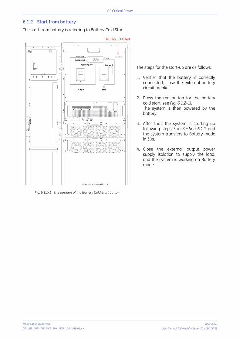
Critical Power
Modifications reserved Page 54/69
GE_UPS_OPM_TLE_MCE_30K_M18_1GB_V020.docx User Manual TLE Modular Series 30 - 180 CE S1
6.1.2 Start from battery
The start from battery is referring to Battery Cold Start.
Fig. 6.1.2-1 The position of the Battery Cold Start button
The steps for the start-up are as follows:
1. Verifier that the battery is correctly connected; close the external battery circuit breaker.
2. Press the red button for the battery cold start (see Fig. 6.1.2-1). The system is then powered by the battery.
3. After that, the system is starting up following steps 3 in Section 6.1.1 and the system transfers to Battery mode in 30s.
4. Close the external output power supply isolation to supply the load, and the system is working on Battery mode.
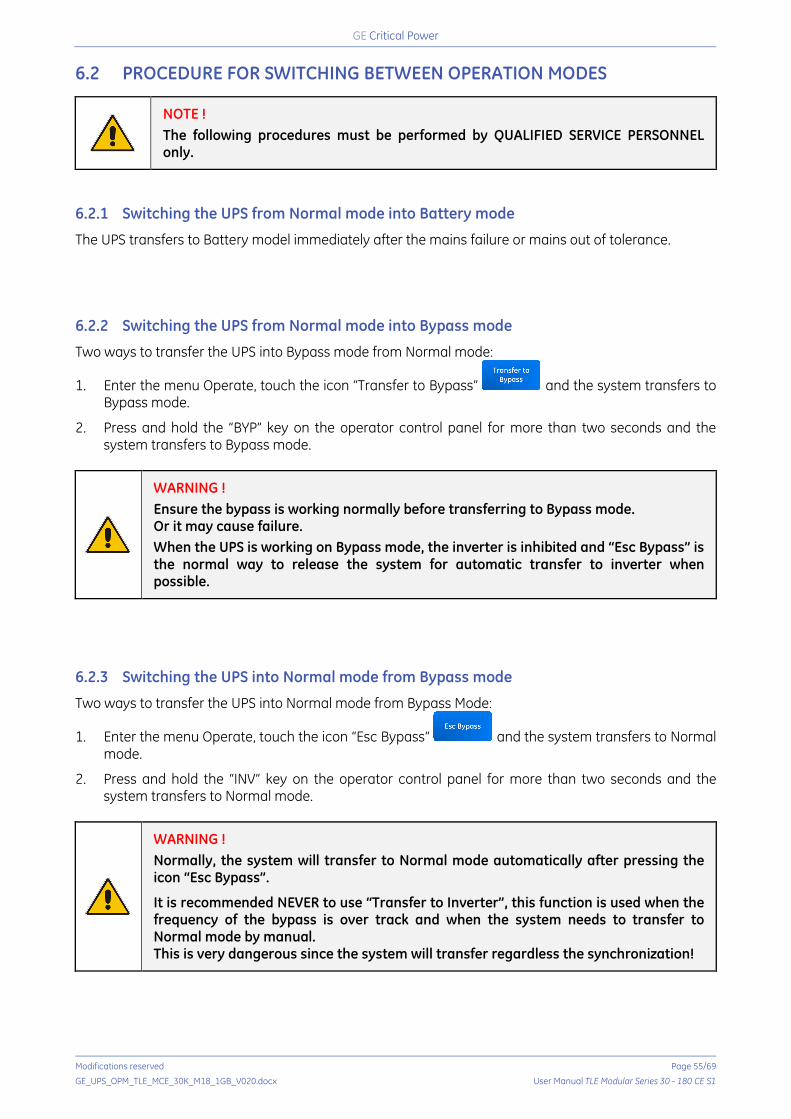
Critical Power
Modifications reserved Page 55/69
GE_UPS_OPM_TLE_MCE_30K_M18_1GB_V020.docx User Manual TLE Modular Series 30 - 180 CE S1
6.2 PROCEDURE FOR SWITCHING BETWEEN OPERATION MODES
NOTE ! The following procedures must be performed by QUALIFIED SERVICE PERSONNEL only.
6.2.1 Switching the UPS from Normal mode into Battery mode
The UPS transfers to Battery model immediately after the mains failure or mains out of tolerance. 6.2.2 Switching the UPS from Normal mode into Bypass mode
Two ways to transfer the UPS into Bypass mode from Normal mode:
1. Enter the menu Operate, touch the icon “Transfer to Bypass” and the system transfers to Bypass mode.
2. Press and hold the “BYP” key on the operator control panel for more than two seconds and the system transfers to Bypass mode.
WARNING ! Ensure the bypass is working normally before transferring to Bypass mode. Or it may cause failure. When the UPS is working on Bypass mode, the inverter is inhibited and “Esc Bypass” is the normal way to release the system for automatic transfer to inverter when possible.
6.2.3 Switching the UPS into Normal mode from Bypass mode
Two ways to transfer the UPS into Normal mode from Bypass Mode:
1. Enter the menu Operate, touch the icon “Esc Bypass” and the system transfers to Normal mode.
2. Press and hold the “INV” key on the operator control panel for more than two seconds and the system transfers to Normal mode.
WARNING ! Normally, the system will transfer to Normal mode automatically after pressing the icon “Esc Bypass”.
It is recommended NEVER to use “Transfer to Inverter”, this function is used when the frequency of the bypass is over track and when the system needs to transfer to Normal mode by manual. This is very dangerous since the system will transfer regardless the synchronization!
Critical Power
Modifications reserved Page 56/69
GE_UPS_OPM_TLE_MCE_30K_M18_1GB_V020.docx User Manual TLE Modular Series 30 - 180 CE S1
6.2.4 Switching the UPS from Normal mode into Maintenance Bypass mode
WARNING ! Before making this operation, be sure that bypass supply is regular and the inverter is synchronous with it.
These following procedures can transfer the load from the UPS inverter output to the maintenance bypass supply, which is used for maintaining the bypass module.
1. Transfer the UPS into Bypass mode following Section 6.2.2.
2. Open the battery breaker and close the “maintenance bypass breaker Q2”.
3. Open the “static bypass breaker Q5” and the load is powered through maintenance bypass.
4. Pull out the bypass module to completely shut down the UPS electronics. 6.2.5 Switching the UPS into Normal Mode from Maintenance Bypass Mode
These following procedures can transfer the load from the Maintenance Bypass mode to inverter output.
1. Insert the bypass module, the static bypass will automatically turn on 30s after the touch screen. The bypass indicator LED will turn ON, the load is powered through maintenance bypass and static bypass.
2. Close the “static bypass breaker Q5”.
3. Switch OFF the “maintenance bypass breaker Q2”. The load is now supplied by the static bypass, the rectifier(s) and inverter(s) will start automatically.
4. After approximately 60s the system transfers to Normal mode.
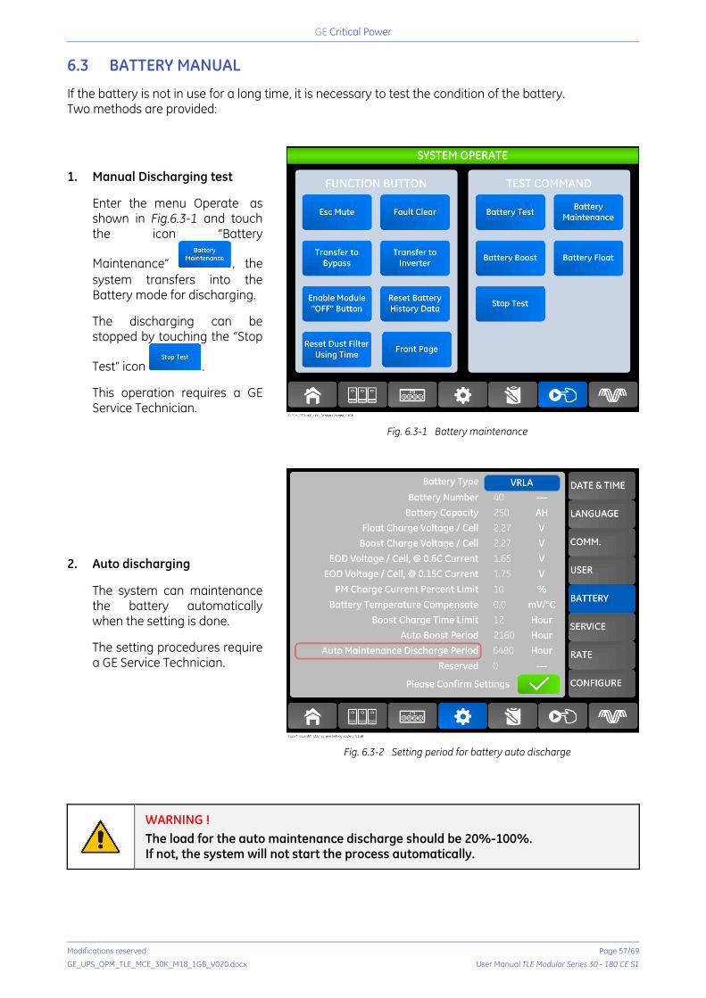
Critical Power
Modifications reserved Page 57/69
GE_UPS_OPM_TLE_MCE_30K_M18_1GB_V020.docx User Manual TLE Modular Series 30 - 180 CE S1
6.3 BATTERY MANUAL
If the battery is not in use for a long time, it is necessary to test the condition of the battery. Two methods are provided:
1. Manual Discharging test Enter the menu Operate as shown in Fig.6.3-1 and touch the icon “Battery
Maintenance” ,the system transfers into the Battery mode for discharging. The discharging can be stopped by touching the “Stop
Test” icon . This operation requires a GE Service Technician.
Fig. 6.3-1 Battery maintenance
2. Auto discharging The system can maintenance the battery automatically when the setting is done. The setting procedures require a GE Service Technician.
Fig. 6.3-2 Setting period for battery auto discharge
WARNING ! The load for the auto maintenance discharge should be 20%-100%. If not, the system will not start the process automatically.

Critical Power
Modifications reserved Page 58/69
GE_UPS_OPM_TLE_MCE_30K_M18_1GB_V020.docx User Manual TLE Modular Series 30 - 180 CE S1
6.4 EPO – EMERGENCY POWER OFF
Fig. 6.4-1 EPO Button The EPO button located in the operator control and display panel (see Fig.6.4-1) is designed to switch OFF the UPS in emergency situations (e.g., fire, flood, etc.). Once pressed the EPO button, the system will turn OFF the rectifier, inverter, stop powering the load and charging the battery immediately. If the input Mains is present, the UPS control circuit will remain active, the EPO can be reset from the
menu Operate, touch the icon . Attention: this operation requires a GE SERVICE TECHNICIAN. To completely isolate the UPS, users need to open the external mains input supply to the UPS. Users can restart the UPS by powering the UPS again.
WARNING !
When the EPO is triggered, the load is not powered by the UPS.
Be careful to use the EPO function.
Critical Power
Modifications reserved Page 59/69
GE_UPS_OPM_TLE_MCE_30K_M18_1GB_V020.docx User Manual TLE Modular Series 30 - 180 CE S1
7 MAINTENANCE
WARNING ! All maintenance and service works must be performed by QUALIFIED SERVICE PERSONNEL. Refer to the “SAFETY RULES” described on Chapter 1.
7.1 GENERAL MAINTENANCE
A UPS system, like other electrical equipment, needs periodic preventive maintenance. A regular maintenance check of your installation guarantees higher reliability of your safe power supply. GE recommends to perform the first service within 12 months from the commissioning date or within 18 months from delivery date. Subsequent services to perform every 12 months. Preventive maintenance work on the UPS can be done only by trained SERVICE TECHNICIANS. We therefore recommend you sign a Maintenance and Service contract with the local GE SERVICE CENTRE organisation. 7.2 SERVICE CHECK
Some components of the UPS which need periodic maintenance, if not replaced, could cause a reliability reduction of the supply system. We highly recommend that you contact your GE SERVICE CENTRE for preventive maintenance work.
NOTE ! Failure to perform mandatory preventative maintenance on components documented in the UPS product manual may result in thermal damage to the equipment, its surroundings, and an increased risk of personnel injury.

Critical Power
Modifications reserved Page 60/69
GE_UPS_OPM_TLE_MCE_30K_M18_1GB_V020.docx User Manual TLE Modular Series 30 - 180 CE S1
7.3 BATTERY MAINTENANCE
NOTE ! Perform mandatory battery maintenance per battery’s manufacturer product manual. This includes electrical and thermal measurements, inspection, cleaning, replacement and re-torque of connections.
Failure to perform proper maintenance on the battery, per the battery manufacturer’s recommendation, including scheduled battery replacement, may result in thermal damage to the equipment and an increased risk of personnel injury.
GE declines any responsibility for any damage to the system and the surrounding caused by battery when the battery maintenance program is provided by other than GE itself and GE authorized partners.
For the Lead-Acid maintenance free battery, when maintenance the battery according to requirements, battery life can be prolonged. The battery life is mainly determined by the following factors: 1. Installation
The battery should be placed in dry and cool place with good ventilation. Avoid direct sunlight and keep away from heat source. When installing, ensure the correct connection to the batteries with same specification.
2. Temperature
The most suitable storage temperature is 20 ºC to 25ºC. 3. Charging/discharging current
The best charging current for the lead-acid battery is 0.1C. The maximum charging current for the battery can be 0.2C. The discharging current should be 0.05C-3C.
4. Charging voltage
In most of the time, the battery is in standby state. When the Mains is normal, the system will charge the battery in Boost mode (constant voltage with maximum limited) to full and then transfers to the state of float charge.
5. Discharge depth
Avoid deep discharging; which will greatly reduce the life time of the battery. When the UPS runs in Battery mode with light load or no load for a long time, it will cause the battery to deep discharge.
6. Check periodically
Observe if any abnormality of the battery, measure if the voltage of each battery are in balance. Discharge the battery periodically.

Critical Power
Modifications reserved Page 61/69
GE_UPS_OPM_TLE_MCE_30K_M18_1GB_V020.docx User Manual TLE Modular Series 30 - 180 CE S1
8 OPTION 8.1 OPTIONS GENERAL VIEW
Parallel System Kit
Allows extending the unit to a Parallel System with 2 or up to 3 units connected on the same bus, which ensure the highest reliability rate and increase the power availability without prior investments.
CB3 battery breaker box
Permits the operator to connect and disconnect the external battery to the UPS. Dimensions (W x D x H): 385 x 180 x 640 mm
Empty battery cabinet
Depending on model the battery extensions can be housed in additional cabinets with the same design of the UPS cabinet, delivered with the necessary protection and connection material. Dimensions (W x D x H): 790 x 1100 x 1600 mm
Battery cabinet 1x33Ah, 2x33Ah and 3x33Ah
Cabinet with a battery that has similar characteristics and is the same size as a UPS, which allows an increase in autonomy in the event of a power cut. Dimensions (W x D x H): 790 x 1100 x 1600 mm
OPT_CB3_250_01
TLESM_030-180_Battery cabinet_01a
TLESM_030-180_Battery cabinet_01a

Critical Power
Modifications reserved Page 62/69
GE_UPS_OPM_TLE_MCE_30K_M18_1GB_V020.docx User Manual TLE Modular Series 30 - 180 CE S1
8.2 OPTIONS ASSEMBLY AND CONNECTION
8.2.1 Battery cabinet 1x33Ah/ 2x33Ah / 3x33Ah
WARNING ! The installation and cabling of the battery cabinet must be performed by QUALIFIED SERVICE PERSONNEL. Make sure that the UPS installation is completely powered down and the battery breaker must be open (Pos. O). Check for sufficient floor loading capacity. Before closing the battery breaker verify the correct polarity of the battery connection.
Battery cabinet
Battery 1x33Ah 2x33Ah 3x33Ah Dimensions 790 x 1100 x 1600 mm (W x D x H) Weight 725 kg 1135 kg 1550 kg Floor loading 835 kg /m2 1306 kg /m2 1785 kg /m2 The battery cabinet can be located on either side of the UPS. Battery connection cables are connected to bus bars using M10. The bolts of the connection cables must be tightened with a torque wrench at 40Nm.
UPS model Protections for mains voltages (3 x 380V / 400V / 415 Vac)
Cables section / IEC 60950-1 Local Standard and cables
installation disposal shall be applied TLE Modular Series 180/30 3 x 80A 3 x 16 + 16 mm2 TLE Modular Series 180/60 3 x 160A 3 x 50 + 25 mm2 TLE Modular Series 180/90 3 x 250A 3 x 120 + 70 mm2 TLE Modular Series 180/120 3 x 300A 3 x 150 + 95 mm2 TLE Modular Series 180/150 3 x 355A 3 x 185 + 95 mm2 TLE Modular Series 180/180 3 x 400A 3 x 240 + 120 mm2
Fig. 8.2.1-1 Battery cabinet connection
Battery cabinet connection - = Negative pole of the battery N = Neutral of battery blocks + = Positive pole of the battery PE = Battery cabinet ground
NOTE ! It is mandatory to ground the battery cabinet to UPS!
+ N -
Bus bars connections of the UPSBattery cabinet
Battery
+N
-
PE
PE
TLESM_030-180_Connection battery cabinet_01GB-a
+ NPE -

Critical Power
Modifications reserved Page 63/69
GE_UPS_OPM_TLE_MCE_30K_M18_1GB_V020.docx User Manual TLE Modular Series 30 - 180 CE S1
Fig. 8.2.1-2 Battery temperature sensor connection
Battery temperature sensor
In addition is available a cable (standard length: 5m) with the battery temperature sensor.
This is to compensate the battery charge voltage (only for type VRLA without maintenance) based on the working temperature.
The battery temperature sensor must be mounted and fixed in the battery cabinet while the "connector 2P" must be connected to "J2 - Dry contact interface" of the UPS.
If the battery cabinet is not mounted side by side of the UPS, the cable connecting the temperature sensor to the UPS should be run in a protective conduit.
8.2.2 Empty battery cabinet
Fig. 8.2.2-1 Empty battery cabinet
Empty battery cabinet Empty battery cabinet with inside the battery breaker only, designed to put inside battery different than 33Ah. Dimensions (W x D x H): 790 x 1100 x 1600 mm
Fig. 8.2.2-2 Battery breaker’s tripping curve
NOTE !
Size battery autonomy and capacity according to the battery breaker’s tripping curve, see Fig. 8.2.2-2.
Dry contact interface of the UPSBattery cabinet
J2 / Dry contact interface
J2TLESM_030-180_Battery temperature sensor connection_01GB-a
Temperaturesensor
Connector2P
TLESM_030-180_Battery cabinet_01a
Critical Power
Modifications reserved Page 64/69
GE_UPS_OPM_TLE_MCE_30K_M18_1GB_V020.docx User Manual TLE Modular Series 30 - 180 CE S1
9 SECURE DEPLOYMENT GUIDE 9.1 INTRODUCTION
This document provides information that can be used to help improve the cyber security of systems that include UPS, SNMP/Web adapter and other connectivity products. It is intended for use by service engineers, integrators, IT professionals, and developers responsible for deploying and configuring UPS systems and connectivity products. Security is the process of maintaining the confidentiality, integrity, and availability of a system: • Confidentiality: Ensure only the people you want to see information can see it; • Integrity: Ensure the data is what it is supposed to be; • Availability: Ensure the system or data is available for use. GE recognizes the importance of building and deploying products with these concepts in mind and encourages customers to take appropriate care in securing their GE products and solutions. Firewalls and other network security products, including Data Diodes and Intrusion Prevention Devices, can be an important component of any security strategy. However, a strategy based solely on any single security mechanism will not be as resilient as one that includes multiple, independent layers of security. Therefore, GE recommends taking a “Defence in Depth” (DiD) approach to security. Defence in Depth is the concept of using multiple, independent layers of security to raise the cost and complexity of a successful attack. To carry out a successful attack on a system, an attacker would need to find not just a single exploitable vulnerability, but would need to exploit vulnerabilities in each layer of defence that protects an asset. 9.2 GENERAL RECOMMENDATIONS
The following security practices should be followed when using GE products and solutions. • The UPS devices and connectivity products covered in this document were not designed for or
intended to be connected directly to any wide area network, including but not limited to a corporate network or the Internet at large. Additional routers and firewalls that have been configured with access rules customized to the site's specific needs must be used to access devices described in this document from outside the local control networks. If a system requires external connectivity, care must be taken to control, limit, and monitor all access, using, for example, virtual private networks (VPN) or Demilitarized Zone (DMZ) architectures.
• Harden system configurations by enabling/using the available security features, and by disabling
unnecessary ports, services, functionality, and network file shares. • Apply all of the latest software/firmware patches (ECN process). • Use whitelisting software on UPS monitoring systems and keep the whitelist up-to-date.

Critical Power
Modifications reserved Page 65/69
GE_UPS_OPM_TLE_MCE_30K_M18_1GB_V020.docx User Manual TLE Modular Series 30 - 180 CE S1
9.3 CHECKLIST
This section provides a sample checklist to help guide the process of securely deploying UPS system and connectivity products. 1. Create or locate a network diagram. 2. Identify and record the required communication paths between nodes. 3. Identify and record the protocols required along each path, including the role of each node. 4. Revise the network as needed to ensure appropriate partitioning, adding firewalls or other network
security devices as appropriate. Update the network diagram. 5. Configure firewalls and other network security devices. 6. Enable and/or configure the appropriate security features on each device. 7. On each device, change every supported password to something other than its default value.
Encourage users to schedule password changes and use passwords of certain complexity. 8. Harden the configuration of each device, disabling unneeded features, protocols and ports. 9. Implement controlled physical access to the UPS device and/or UPS room. 10. Discourage user from bridging RS232/RS485 Modbus to Ethernet.
For cases that product application absolutely requires such setup, recommend deploying a Modbus firewall device in front of the bridge and set particular configuration that would filter out all Modbus registers contributing to possible vulnerabilities. Provide user with ideas how to reduce surface of attack by limiting Modbus communications to specific IP source addresses and specific operations (read-only vs. read-write), etc.
11. Test/qualify the system. 12. Create an update/maintenance plan. 9.4 COMMUNICATION REQUIREMENTS
Communication between different parts of a system is, and must be, supported. However, the security of a system can be enhanced by limiting the protocols allowed, and the paths across which they are allowed, to only what is needed. This can be accomplished by disabling every communication protocol that isn’t needed on a particular device, and by using appropriately configured and deployed network security devices (for example, firewalls and routers) to block every protocol (whether disabled or not) that doesn’t need to pass from one network/segment to another. GE recommends limiting the protocols allowed by the network infrastructure to the minimum set required for the intended application. Successfully doing this requires knowing which protocol is needed for each system-level interaction.
Critical Power
Modifications reserved Page 66/69
GE_UPS_OPM_TLE_MCE_30K_M18_1GB_V020.docx User Manual TLE Modular Series 30 - 180 CE S1
9.5 SECURITY CAPABILITIES
Security features available in each device can be used as part of a defence-in-depth strategy to secure a system.
9.5.1 Physical security perimeter protection
1. All hardware should be placed in locked cabinets/rooms, with policies and procedures to restrict access to the key.
2. Network equipment such as switches, routers, firewalls, and Ethernet cabling should be physically protected in locked enclosures such as cabinets or closets with policies and procedures to restrict access to these enclosures.
3. Whenever possible, there should be no physical network path from an UPS or connectivity device to the Internet. It should not be possible for an attacker to reach UPS system network from any Internet-facing computer.
4. Networks should always be physically segmented to avoid exposure of UPS and connectivity device networks.
5. Each UPS system asset should be visibly labelled by a unique identifier, with all expected asset identification compiled into an access controlled list.
9.5.2 Electronic security perimeter protection
1. All external access to a UPS network should be managed through a Virtual Private Network (VPN) or similar technology leveraging two-factors authentication (2FA).
2. Next-Generation Firewalls should be properly configured and deployed at each conduit between physical networks that deny all but the specifically allowed protocol families, source addresses, and destination addresses, and specific application-level commands between the two adjacent networks. For example, a Next-Generation Firewall could prohibit write operations across networks while allowing read operations.
3. If one network node such as a PLC or HMI uses unauthenticated protocols to exchange information or commands with another network node on the same physical network, a Next-Generation Firewall could be deployed between the two network nodes. This Next-Generation Firewall should be configured to explicitly whitelist all expected messages between the two network nodes, and deny all other unexpected messages.
4. To detect and alert for unexpected, unauthenticated messages on a given network, an Intrusion Detection System (IDS) could be configured and deployed. Consider configuring the IDS to log all events to a Security Information and Event Management (SIEM) system that aggregates all security information on the ICS network.
5. To detect and actively prevent unexpected, unauthenticated messages on a given network from reaching a given network node, an Intrusion Prevention System (IPS) could be configured and deployed. Consider configuring the IPS to log all events to a Security Information and Event Management (SIEM) system that aggregates all security information on the ICS network.
6. To limit the impact of the compromise of any single user account, it is recommended to divide administrator’s privileges into several user accounts, each for its own operational function.
7. To limit the impact of the compromise of any single set of credentials (user name, password) for any equipment in the UPS network, it is recommended to never re-use credentials for different tools or purposes.
8. Carefully protect sources of and access to credentials (user names, passwords) for all UPS and connectivity devices, including switches, routers, firewalls, IDS, IPS, etc.
9. Enforce a policy of rotating credentials for equipment periodically and after personnel changes. Note that products with no support for enforcement of unique passwords over time should be compensated for with policies and procedures that require a history of unique passwords.

Critical Power
Modifications reserved Page 67/69
GE_UPS_OPM_TLE_MCE_30K_M18_1GB_V020.docx User Manual TLE Modular Series 30 - 180 CE S1
9.5.3 Password management
GE strongly recommends the use of long (12 characters or more), complex passwords wherever passwords are used for authentication. Whenever using a password scheme with a fixed maximum character length for passwords, GE recommends setting passwords to utilize the full character length available whenever possible in order to make it more difficult for attackers to crack passwords. 9.6 CONFIGURATION HARDENING
This section is intended to reduce the potential attack surface by providing information that can be used to harden the configuration of the UPS system and connectivity products that are present in a particular installation. Configuration Hardening should be considered in addition to enabling and using security features such as Authentication, Access Control and Authorization. GE recommends disabling, on each product, all ports, services and protocols that aren’t required for the intended application. The Ethernet Interface can be configured to disable a number of services, such as ftp, http, telnet. Note that some of these settings will not entirely close the TCP/UDP port, but they will still reduce the attack surface. 9.7 NETWORK BANDWIDTH LIMITING
In order to reduce the likelihood of intentional or accidental network flooding that could cause a loss of availability of an Ethernet interface, GE strongly encourages following the relevant recommendations in the section “9.5 - SECURITY CAPABILITIES”. To further mitigate the loss of availability for a particularly critical asset, a switch or firewall configured for ingress and egress rate-limiting can be placed directly between the UPS or connectivity devices and the rest of the network. In the event of a network storm, the switch or firewall will selectively drop traffic to limit the rate of traffic that reaches a given device. 9.8 SOFTWARE UPDATES AND PATCH MANAGEMENT
A strategy for applying security fixes, including firmware updates, and configuration changes, should be included in a facility’s security plan. Applying these updates will often require that an affected product be temporarily taken out of service. Only GE representative are allowed to perform maintenance on UPS or connectivity devices. They are allowed to: • Collect/fetch the GE recommended firmware/software from GE secured storage/sources; • Perform firmware/software upgrade or modify parameters or configuration on GE devices. Finally, some installations require extensive qualification be performed before changes are deployed to the production environment. While this requirement is independent of security, ensuring the ability to promptly apply security fixes while minimizing downtime may drive the need for additional infrastructure to help with this qualification. 9.9 GOVERNMENT AGENCIES AND STANDARDS ORGANIZATIONS
Government agencies and international standards organizations may provide guidance on creating and maintaining a robust security program, including how to securely deploy and use Industrial Control Systems. For example, the U.S. Department of Homeland Security has published guidance on Secure Architecture Design and on Recommended Practices for cybersecurity with Industrial Control Systems. Similarly, the International Society of Automation publishes the ISA-99 specifications to provide guidance on establishing & operating a cyber-security program, including recommended technologies for industrial automation and control systems. Such documentation, when appropriate, should be considered in addition to this document.
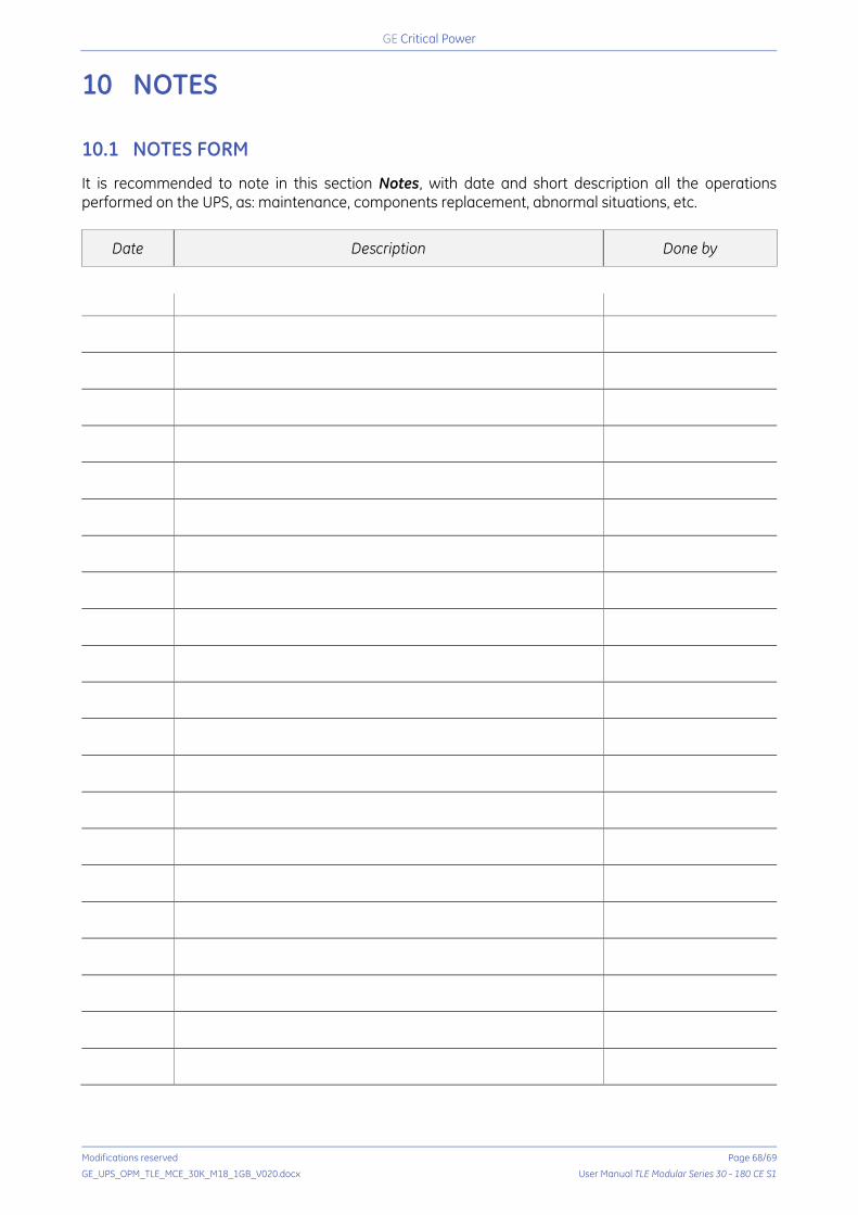
Critical Power
Modifications reserved Page 68/69
GE_UPS_OPM_TLE_MCE_30K_M18_1GB_V020.docx User Manual TLE Modular Series 30 - 180 CE S1
10 NOTES 10.1 NOTES FORM
It is recommended to note in this section Notes, with date and short description all the operations performed on the UPS, as: maintenance, components replacement, abnormal situations, etc.
Date Description Done by
Critical Power
Modifications reserved Page 69/69
GE_UPS_OPM_TLE_MCE_30K_M18_1GB_V020.docx User Manual TLE Modular Series 30 - 180 CE S1
11 ANNEX 11.1 CD-ROM
CD-Rom
The enclosed CD-Rom contains the complete documentation in various languages. List of documents contained in the CD: - User Manual - English version - User Manual - German version - User Manual - Spanish version - User Manual - French version - User Manual - Italian version - User Manual - Dutch version - Technical Data Sheet - English version - Technical Data Sheet - German version - Technical Data Sheet - Spanish version - Technical Data Sheet - French version - Technical Data Sheet - Italian version - Technical Data Sheet - Dutch version - UPS schematic diagrams


![TLE ANALYSER · TLE ANALYSER User Manual v2.8 TLE analysis ... TLE ANALYSER Version 2.8 - 2013 TLE ANALYSER - User Manual [4] 2. TLE Analyser Setup and Options TLE Updater allow to](https://img.dokumen.tips/doc/110x75/5aa68a5c7f8b9a517d8ea13c/tle-analyser-analyser-user-manual-v28-tle-analysis-tle-analyser-version-28.jpg)