Embed Size (px)
Citation preview

TKB 3415 - Description of the Serial Interface 2WR5 for firmware versions 2.12 and higher
Landis + Gyr GmbH, US R&D Page 1 of 34 Achim Reissinger G:\DOK\TKB\Schnittstellen-Beschreibungen\2wr5\englisch\TKB3415j_e.DOC
09.11.04
Contents
1 OVERVIEW................................................................................................................................................... 2
1.1 OPERATING MODES OF THE HEAT METER ...................................................................................................... 3 1.2 SOFTWARE SUPPORT..................................................................................................................................... 3
2 OPTICAL INTERFACE............................................................................................................................... 4
2.1 DEFINITIONS AND CONVENTIONS FOR THE OPTICAL INTERFACE .................................................................... 4 2.2 BAUD RATE................................................................................................................................................... 4 2.3 HEADER........................................................................................................................................................ 4 2.4 PSEUDO HEX CODE ....................................................................................................................................... 4 2.5 STRUCTURE OF THE TELEGRAMS................................................................................................................... 5 2.6 DATA TRAFFIC .............................................................................................................................................. 5
2.6.1 Data traffic in normal mode ................................................................................................................ 5 2.6.1.1 With test seal.....................................................................................................................................................5 2.6.1.2 Without test seal ...............................................................................................................................................6
2.6.2 Data traffic when ready for testing...................................................................................................... 6 2.6.3 Data traffic in calibration mode .......................................................................................................... 7
3 PULSE INTERFACE .................................................................................................................................... 7
3.1 FUNCTION CV (COUNT VOLUME).................................................................................................................. 7 3.2 FUNCTION CT (COUNT TARIFF)..................................................................................................................... 7 3.3 FUNCTION RI (READY INDICATOR) ............................................................................................................... 8 3.4 OUTPUT OF FAST PULSES (PULSE AND M BUS COMBI MODULE)..................................................................... 8
4 20MA INTERFACE ...................................................................................................................................... 8
4.1 PHYSICAL LEVEL........................................................................................................................................... 8 4.2 CALL-UP ....................................................................................................................................................... 8 4.3 DATA TELEGRAM.......................................................................................................................................... 9
5 M-BUS ............................................................................................................................................................ 9
6 READ-OUT TELEGRAMS.......................................................................................................................... 9
6.1 NUMBER CODES............................................................................................................................................ 9 6.2 MANDATORY TELEGRAM (ONLY THROUGH THE OPTICAL INTERFACE) ........................................................ 10 6.3 OPTIONAL TELEGRAMS (WITH OPT. INTERFACE, AND CL (COMBI) MODULE AND MODEM MODULE............. 10 6.4 EB TELEGRAM (ONLY THROUGH THE OPTICAL INTERFACE) ......................................................................... 14
7 NOWA TEST ............................................................................................................................................... 15
8 LCD FUNCTIONS ...................................................................................................................................... 15
8.1 LOCKING THE LCD (COMMISSIONING LOCK) .............................................................................................. 15 8.2 LOCKING THE LCD (CALL-UP) BUTTON ...................................................................................................... 15 8.3 LOCKING THE EXTENDED LCD LOOP (SERVICE LOOP) ................................................................................ 15 8.4 LCD SWITCH-OFF ....................................................................................................................................... 15
9 APPENDIX................................................................................................................................................... 16
9.1 TABLE 3: TELEGRAMS 2WR5 – OVERVIEW ............................................................................................. 16 9.2 TABLE 4: CODE NUMBERS FOR DATA TELEGRAMS 2WR5 - OVERVIEW ...................................................... 25 9.3 TABLE 5: CODE NUMBERS FOR DATA TELEGRAMS 2WR5 - DESCRIPTION .................................................. 28

TKB 3415 - Description of the Serial Interface 2WR5
Landis + Gyr GmbH, US R&D Page 2 of 34 Achim Reissinger G:\DOK\TKB\Schnittstellen-Beschreibungen\2wr5\englisch\TKB3415j_e.DOC
09.11.04
1 Overview This description applies to heat meters of type 2WR5. Further documentation is available for the 2WR5 heat meter:
− Brochure 2WR5 − Operating instructions 2WR5 − Construction description − Testing and calibration description ________ TKB 3412 − Description of M-bus___________________ TKB 3402 − Description of PAPPA software __________ TKB 3404 − Description of modem module − Description of CL module _______________ TKB 3408 (already contained in this document)
The standard equipment of 2WR5 heat meters includes an EN 1434-3 bidirectional optical interface (2.2 optical interface). This interface is used
− to read out data from the unit locally − to test the heat meter − for parameterization and calibration in a test center
In addition to the optical interface, the heat meter can be equipped with an I/O module. This module can be
− a pulse module for controlling external metering or monitoring equipment or − a CL module for reading out the heat meter using a twisted-pair connection or − an M-bus module for connection to the M-bus or to an inductive read-out head or − a modem module for connecting an analog phone line or − a CL combi module with a 20mA output for connecting a read-out device and two pulse outputs
for controlling external metering equipment or − an M-bus combi module with an output for connecting the M-bus or an inductive read-out head
and a pulse output for controlling external metering equipment
M-bus interface
current loop interface
pulse outputs
optical interface
M-busmodule
(optional)
pulse module(optional)
current loopmodule
(optional)
heat meter 2WR5
Pay attention: Only one optional module is possible!
current loopcombi module
(optional)
pulse outputs
current loop interface
M-bus combimodule
(optional) M-bus interface
pulse output
modemmodule
(optional)telephone line
The connected I/O module is automatically detected by the heat meter and can be equipped subsequently (plug-and-play). The M-bus combi module and modem module are recognized as M-bus modules.

TKB 3415 - Description of the Serial Interface 2WR5
Landis + Gyr GmbH, US R&D Page 3 of 34 Achim Reissinger G:\DOK\TKB\Schnittstellen-Beschreibungen\2wr5\englisch\TKB3415j_e.DOC
09.11.04
1.1 Operating modes of the heat meter The heat meter has various operating modes. The optical interface must be controlled differently in each mode. That is why it is necessary to synchronize the controlling program with the heat meter. That is done with a "determine status" telegram that is transmitted to the heat meter. This telegram will be answered in every operating mode. The response telegram indicates what operating mode the heat meter is currently in. The operating modes are defined as follows:
− Normal mode (Nb), test seal set: Response = "(Nb+)!" The heat meter is performing flowrate and temperature measurements in the normal timebase. The data exchange is limited to the functions that interfere neither with the meter readings nor with the measuring function of the heat meter. The optical interface operates at 300 baud and is scanned at 1-s intervals when the LCD is permanently switched on. If the LCS is switched off, scanning is only performed when the LCD is lit briefly.
− Normal mode, test seal not set: Response = "(Nb-)!" The heat meter is performing flowrate and temperature measurements in the normal timebase. However, all functions are permissible, including parameterization and call-up of calibration mode. The optical interface communicates at 300 or 2400 baud and is scanned at 1-s intervals.
− Ready for test after call-up of the rolling menu with the test button: Response = "(Pb+)!" or "(Eb-)!", depending on the test seal. The heat meter is waiting for data exchange or button input. The rolling menu is displayed on the LCD (alternate menu display at 1-s intervals). No measurements are performed and the modules are ignored (M-bus, 20mA, pulse, combi, modem module, etc.) are ignored. The optical interface works with 2400 baud and is scanned at 500-ms intervals. When any command telegram is detected, either the information "Pb" (test seal set) or "Eb" (test seal not set) will be displayed on the LCD; the rolling menu will then no longer be displayed.
− Ready for testing (Pb), test seal set: Response = "Pb+" The heat meter is waiting for data exchange. The optical interface works with 2400 baud and is scanned at 500-ms intervals. Calibration telegrams are not permissible, parameterization telegrams are permissible with restrictions.
− Calibration mode (Eb), test seal not set: Response = "Eb+"
The heat meter is waiting for data exchange. The optical interface works with 2400 baud and is scanned at 500-ms intervals. All calibration and parameterization telegrams are permissible.
The "determine status" telegram is identical for all operating modes of the heat meter. At a baudrate of 2400 baud it is possible to acquire the operating modes Nb-, Pb, and Eb. For operating mode Nb+, a baudrate of 300 baud is necessary.
1.2 Software support A program is available for reading out heat meter data and controlling and parameterizing the heat meter through the optical interface. It is called PappaWin (Programm für Auslesen, Prüfung, Parametrierung und Abgleich for Microsoft Windows 3.x/9x/ME/NT/2000/XP). Commercial versions PappaWin Standard and PappaWin Profi and a freeware version PappaWin light of PappaWin are available . The Turbo Pascal unit DatTel can also be provided. The unit is compatible with Borland Pascal 7 and Borland Delphi 1 to 4. In the "DatTel" unit, the string read out of the data telegram is decoded and converted to heat meter data. The unit can be obtained by e-mail from Landis + Gyr.

TKB 3415 - Description of the Serial Interface 2WR5
Landis + Gyr GmbH, US R&D Page 4 of 34 Achim Reissinger G:\DOK\TKB\Schnittstellen-Beschreibungen\2wr5\englisch\TKB3415j_e.DOC
09.11.04
2 Optical interface
2.1 Definitions and conventions for the optical interface Transmission mode: Bit-serial asynchronous (start/stop) transmission acc. to
DIN 66022, semi-duplex Transmission rate 300 or 2400 baud, depending on the operating mode Character format Character format acc. to DIN 66003 (1°start bit, 7°data
bits, 1°parity bit, 2°stop bits) Character code Character code acc. to DIN 66003, international reference
version Character error detection and correction Parity check, even parity acc. to DIN 66022
BCC check acc. to EN 61107 Protocol Acc. to EN 61107 mode B Definitions of the signal level: log. 1 = dark
log. 0 = light For read-out, the optical read-out head acc. to DIN EN 1434-3 is used.
2.2 Baud rate The heat meter communicates at 300 or 2400 baud depending on its operating mode. If the test seal is set and the operating mode is "normal mode" (Nb), the heat meter will always receive 300 bauds. The response telegrams use a different baud rate:
− Acknowledgment telegrams are transmitted at 300 baud (command acknowledgment) − Landis+Gyr-specific data telegrams are transmitted at 2400 baud (Nb optional/mandatory
telegram, EEPROM data) − Standardized data telegrams are transmitted with a special protocol (baud rate switchover to
protocol EN 61107 mode B, but with a shorter transmission pause on switching the baud rate)
In the other operating mode (Pb, Eb), the heat meter only receives and transmits at 2400 baud.
2.3 Header The heat meter can query the optical interface only at fixed time intervals. That is why it is necessary to synchronize data traffic. That is done with a command telegram, called the header, that is transmitted first. This header consists of standard characters (NUL = ASCII code 00H) and is necessary in every telegram. A time interval of 2.2 s between the header and the telegram code is permissible, but not necessary. It is only required to ensure compatibility with other tariff units. The time interval between the characters of a complete telegram must not be more than 10 bit lengths. The header must be no longer than 2.5 s. The recommended length depends on the operating mode of the heat meter, see Table 1. Table 1: Length of the header
Operating mode Baud rate Length of the header Normal mode with a test seal 300 baud 40 NUL char
Normal mode without test seal 2400 baud 229 NUL char Rolling menu (Pb) or calibration mode°(Eb) 2400 baud 130 NUL char
2.4 Pseudo hex code The internal microcomputer of the heat meter has a processing width of 4 bits. That means that certain hex characters have to be transmitted as pseudo hex characters. Hex digits A..F in these characters

TKB 3415 - Description of the Serial Interface 2WR5
Landis + Gyr GmbH, US R&D Page 5 of 34 Achim Reissinger G:\DOK\TKB\Schnittstellen-Beschreibungen\2wr5\englisch\TKB3415j_e.DOC
09.11.04
correspond to ASCII code 3A..3F. Please pay attention to this when generating command telegrams and decoding the response telegram.
Hex characters 0..9 A B C D E F Pseudo hex chars 0..9 : ; < = > ?
2.5 Structure of the telegrams
− Each command telegram has a header and ends with CR/LF. − Each response telegram from the heat meter contains an end code, consisting of the character
"!" + CR/LF. − Each valid command telegram is acknowledge by the heat meter with a response code. − An incorrect or impermissible telegram is also acknowledged by the heat meter with a response
code (in pseudo hex). This error code is described in Table 2.
header
ackn.
data
telegramcode
! CR LF
! CR LF
+
+
+
CR LF+To heat meter:
From heat meter:
or
Table 2: Meaning of the acknowledgment
Ack. Meaning 0 Command executed 1 Syntax error 2 Telegram not defined 3 Pseudo hex figure expected 4 Character expected 5 End code expected 6 LF expected 7 CR expected 8 CR/LF expected 9 Other parameter expected A String expected B Not permissible in Pb C (not defined) D Pause between the characters too long E Header too long F Not permissible in Nb
The data telegrams that the heat meter transmits on request contain the meter readings of the consumption values, the stored yearly, monthly, and maximum values, the actual values, and the calibration and parameter values, etc. On local read-out, the data can be called up in a short form (mandatory telegram) or in a long form (option telegram). The content of the data telegrams is described in Table 5. The telegram structure complies with EN 61107 (BCC check, number codes).
2.6 Data traffic
2.6.1 Data traffic in normal mode
Normal mode permits only telegrams that do not interfere with metering.
2.6.1.1 With test seal
If the test seal is set, the following operations are permissible:

TKB 3415 - Description of the Serial Interface 2WR5
Landis + Gyr GmbH, US R&D Page 6 of 34 Achim Reissinger G:\DOK\TKB\Schnittstellen-Beschreibungen\2wr5\englisch\TKB3415j_e.DOC
09.11.04
− Read-out of the RAM/EEPROM data − Request telegram − Reset maxima − Set customer number − Set M-bus address − Lock service loop − Lock display call-up button − Set system time/system date − Set set day − Set/cancel commissioning lock
2.6.1.2 Without test seal
If the test seal is not set, the following operations are also permissible:
− Reset meter readings (master reset) − Clear faults − Clear missing time / operating time − Call up test/calibration mode
2.6.2 Data traffic when ready for testing
You can only call up this mode by pressing the test button (exception: test seal has not been set or NOWA test has been initialized). After that, the heat meter will display a rolling menu on its LCD. You can use this rolling menu and the display call-up button to start and stop all test modes. After receiving any command telegram, the information "Pb" appears on the LCD. If the unit is ready for testing and the test seal is set, only telegrams that interfere with neither meter readings nor unit parameters are accepted by the heat meter. On return to normal mode, the original meter readings for heat quantity and volume will be restored. The following operations are possible:
− Call up/stop test operation flowrate, volume, temperature, or heat quantity − Request telegram − Set set day − Set customer number − Set period for maximum calculation − Clear faults − Clear missing time / operating time − Reset maxima − Configure fast pulses (with code) − Activate tariff acquisition (with code) − Set the initial functions

TKB 3415 - Description of the Serial Interface 2WR5
Landis + Gyr GmbH, US R&D Page 7 of 34 Achim Reissinger G:\DOK\TKB\Schnittstellen-Beschreibungen\2wr5\englisch\TKB3415j_e.DOC
09.11.04
Do not remove the optical read-out head from the heat meter after you have called up a test mode through the optical interface. If you do, test mode will be terminated too early as soon as another light source falls on the optical interface. Alternatively, you can cover the optical interface with, for example, a coin.
2.6.3 Data traffic in calibration mode Only ever call up this mode when the test seal is reset. Otherwise, the calibration mark will be destroyed and the calibration button operated, which would reset the test seal. Calibration mode permits complete parameterization of the heat meter. You can also call up all functions of the "ready for testing" mode. Calibration mode can be called up from normal mode by telegram if the test seal is not set. The following operations are also possible:
− Set the measuring path − Set the sensor type − Configure the LC display − Define the installation location − Set the calibration values − Activate simulation − Set the unit number − Switch over operating time/missing time recording − Set set seal − Initialize EEPROM − Reset meter readings (master reset)
3 Pulse interface This interface is available after insertion of the pulse or combi module and is used for remote display of heat quantity and volume or display of the fault state of the heat meter. The function is parameterized by telegram for
− Remote display of heat quantity and volume (function CV) or − Remote display of heat quantity and tariff register 1 (function CT) or − Remote display of heat quantity and display of the error state (function RI) or − Output of fast impulses
The interface is isolated from the heat meter (optocoupler).
3.1 Function CV (count volume) Output of remote display of heat quantity and volume:
− Pulse length 100 ms (low resistance) − Pulse spacing > 100 ms
3.2 Function CT (count tariff) Output of remote display of heat quantity and tariff register 1:
− Pulse length 100 ms (low resistance) − Pulse spacing > 100 ms

TKB 3415 - Description of the Serial Interface 2WR5
Landis + Gyr GmbH, US R&D Page 8 of 34 Achim Reissinger G:\DOK\TKB\Schnittstellen-Beschreibungen\2wr5\englisch\TKB3415j_e.DOC
09.11.04
3.3 Function RI (ready indicator) Output of the error state:
− If OK: Pulses of length 100 to 250 µs (low resistance) − If error: No pulse output; static signal (high resistance) − Repeat time 500 ms
3.4 Output of fast pulses (pulse and M bus combi module) Fast pulses are always output at the heat quantity output. That also applies to use of fast volume pulses! Fast pulses can be parameterized proportionally to the flowrate and/or power within broad limits (0.01 Hz to 33 Hz; 2 ms to 100 ms pulse length). It is also possible to set minimum and maximum values. Parameterization is easy with PappaWin (see Chapter 1.2).
Fast pulses can be output on the pulse and M bus combi module but not on the CL combi module!
After switchover or insertion of a new module, the previously programmed function is retained.
4 20mA interface This interface is available after you have inserted a CL or CL combi module. It is used
− for fixed connection: in building services management system or − for mobile connection: for data read-out at the front door or garden gate
The interface is isolated from the heat meter. This interface is not bidirectional! You can only read out the optional data via the electrical interface. Addressing is not possible.
Note: The 20mA interface is controlled only in operating mode Nb.
4.1 Physical level Definition of the signal level: log. 1: I = 11..30 mA (quiescent current) log. 0: I = 0..2.5 mA
4.2 Call-up The data request for the data telegram is made by a 0-1 signal edge on the RTX line. The simplest case is a short interruption of the loop current or transmission of a dummy character. The response time of the heat meter is 0.5 to 2 seconds.
TKB 3415 - Description of the Serial Interface 2WR5
Landis + Gyr GmbH, US R&D Page 9 of 34 Achim Reissinger G:\DOK\TKB\Schnittstellen-Beschreibungen\2wr5\englisch\TKB3415j_e.DOC
09.11.04
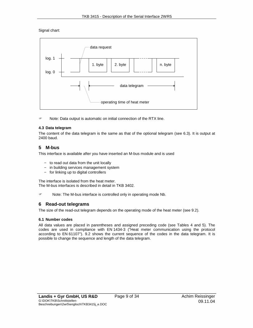
Signal chart:
log. 1
log. 0
data request
data telegram
operating time of heat meter
1. byte 2. byte n. byte
Note: Data output is automatic on initial connection of the RTX line.
4.3 Data telegram The content of the data telegram is the same as that of the optional telegram (see 6.3). It is output at 2400 baud.
5 M-bus This interface is available after you have inserted an M-bus module and is used
− to read out data from the unit locally − in building services management system − for linking up to digital controllers
The interface is isolated from the heat meter. The M-bus interfaces is described in detail in TKB 3402.
Note: The M-bus interface is controlled only in operating mode Nb.
6 Read-out telegrams The size of the read-out telegram depends on the operating mode of the heat meter (see 9.2).
6.1 Number codes All data values are placed in parentheses and assigned preceding code (see Tables 4 and 5). The codes are used in compliance with EN 1434-3 ("Heat meter communication using the protocol according to EN 61107"). 9.2 shows the current sequence of the codes in the data telegram. It is possible to change the sequence and length of the data telegram.

TKB 3415 - Description of the Serial Interface 2WR5
Landis + Gyr GmbH, US R&D Page 10 of 34 Achim Reissinger G:\DOK\TKB\Schnittstellen-Beschreibungen\2wr5\englisch\TKB3415j_e.DOC
09.11.04
6.2 Mandatory telegram (only through the optical interface) The mandatory telegram contains the following data: − Unit and customer number, measuring range, system data and time − Current fault display − Current values for heat quantity, volume, tariff register, and fault duration − Previous year's values for heat quantity, volume, tariff register, and fault duration − Set day − Operating duration − Measuring period − Current maximum values for flowrate, temperatures, heat power, − Parameterization, for example, installation location, simulation of the return sensor − Tariff parameters − Timestamp Example of the content of a mandatory telegram (length about 746 characters): /LUGC2WR5 (CR) (LF) (STX)6.8(0000000*kWh)6.26(00000.00*m3)9.21(00000000) 6.26*01(00000.00*m3)6.8*01(0000000*kWh) F(5)9.20(00000000)6.35(60*m) 6.6(0000.0*kW)6.6*01(0000.0*kW)6.33(000.000*m3ph)9.4(054*C&140*C) 6.31(0000016*D)6.32(0000015*D)9.22(R)9.6(000&00000000&0)9.7(10000) 6.32*01(0000000*D)6.36(01-01)6.33*01(000.000*m3ph) 6.8.1()6.8.2()6.8.3()6.8.4()6.8.5() 6.8.1*01()6.8.2*01()6.8.3*01() 6.8.4*01()6.8.5*01() 9.4*01(000*C&000*C) 6.36.1(2000-00-00)6.36.1*01(2000-00-00) 6.36.2(2000-00-00)6.36.2*01(2000-00-00) 6.36.3(2001-08-01)6.36.3*01(2000-00-00) 6.36.4(2001-08-03)6.36.4*01(2000-00-00) 6.36.5(2000-00-00)6.36*02(01)9.36(2001-08-17&06:00:38)9.24(1.5*m3ph) 9.17(0)9.18()9.19()9.25()9.29() 9.1(0&2&0&-&CV&0&2.11)9.2(&&)0.0(00000000)! (CR) (LF) (ETX) (BCC) (NUL)
6.3 Optional telegrams (with opt. interface, and CL (combi) module and modem module The optional telegram contains the data of the mandatory telegram, and also: − Stored monthly values such as, for example, heat quantity, volumes, maxima − Calibration values − Measuring path parameters − Temperature sensor parameters − Detailed fault data − Actual values, for example, flowrate, temperatures, heat power − Contents of the prescaler for heat quantity and volume − Parameter for fast pulses Example of the content of an optional telegram (length about 10400 characters): /LUGC2WR5 (CR) (LF) (STX)6.8(0000000*kWh)6.26(00000.00*m3)9.21(00000000) 6.4()6.27()6.29(054*C)6.28(140*C)6.30(-085.7*C) 6.26*01(00000.00*m3)6.8*01(0000000*kWh) F(5)9.20(00000000)6.35(60*m) 6.6(0000.0*kW)6.6*01(0000.0*kW)6.33(000.000*m3ph)9.4(054*C&140*C) 6.31(0000016*D)6.32(0000015*D)9.22(R)9.6(000&00000000&0)9.7(10000) 6.32*01(0000000*D)6.36(01-01)6.33*01(000.000*m3ph) 6.8.1()6.8.2()6.8.3()6.8.4()6.8.5() 6.8.1*01()6.8.2*01()6.8.3*01()

TKB 3415 - Description of the Serial Interface 2WR5
Landis + Gyr GmbH, US R&D Page 11 of 34 Achim Reissinger G:\DOK\TKB\Schnittstellen-Beschreibungen\2wr5\englisch\TKB3415j_e.DOC
09.11.04
6.8.4*01()6.8.5*01() 9.4*01(000*C&000*C) 9.4*02(000*C&000*C)6.36.3*02(2000-00-00)6.36.4*02(2000-00-00) 6.33*02(000.000*m3ph)6.36.2*02(2000-00-00) 6.6*02(0000.0*kW)6.36.1*02(2000-00-00)6.32*02(0000000*D) 6.8*02(0000000*kWh)6.8.1*02()6.8.2*02()6.8.3*02() 6.8.4*02()6.8.5*02()6.26*02(00000.00*m3) 6.36.1(2000-00-00)6.36.1*01(2000-00-00) 6.36.2(2000-00-00)6.36.2*01(2000-00-00) 6.36.3(2001-08-01)6.36.3*01(2000-00-00) 6.36.4(2001-08-03)6.36.4*01(2000-00-00) 6.36.5(2000-00-00)6.36*02(01)9.36(2001-08-17&06:23:04)9.24(1.5*m3ph) 9.23(000&800&000&000&000&000&000) 9.17(0)9.18()9.19()9.25()9.29() 9.1(0&2&0&-&CV&0&2.12)9.2(&&)9.3(0000&?:2400&???6:0&=8?000) 9.5(00&00000000&00000000&00&00&:9&17119&874013261120&0000&0000&0<0) 9.5*01(00&0000&65&>=&:9&85&0008000&0001&0000000000000000&0000000000000000) 9.5*02(?00000&?00000&00000000&002=3=&0=:=16&7:6) 9.5*03()9.15()9.16()9.15*01()9.16*01() 9.4*03(000*C&000*C)6.36.3*03(2000-00-00)6.36.4*03(2000-00-00) 6.33*03(000.000*m3ph)6.36.2*03(2000-00-00) 6.6*03(0000.0*kW)6.36.1*03(2000-00-00)6.32*03(0000000*D) 6.8*03(0000000*kWh)6.8.1*03()6.8.2*03()6.8.3*03() 6.8.4*03()6.8.5*03()6.26*03(00000.00*m3) 9.4*04(000*C&000*C)6.36.3*04(2000-00-00)6.36.4*04(2000-00-00) 6.33*04(000.000*m3ph)6.36.2*04(2000-00-00) 6.6*04(0000.0*kW)6.36.1*04(2000-00-00)6.32*04(0000000*D) 6.8*04(0000000*kWh)6.8.1*04()6.8.2*04()6.8.3*04() 6.8.4*04()6.8.5*04()6.26*04(00000.00*m3) 9.4*05(000*C&000*C)6.36.3*05(2000-00-00)6.36.4*05(2000-00-00) 6.33*05(000.000*m3ph)6.36.2*05(2000-00-00) 6.6*05(0000.0*kW)6.36.1*05(2000-00-00)6.32*05(0000000*D) 6.8*05(0000000*kWh)6.8.1*05()6.8.2*05()6.8.3*05() 6.8.4*05()6.8.5*05()6.26*05(00000.00*m3) 9.4*06(000*C&000*C)6.36.3*06(2000-00-00)6.36.4*06(2000-00-00) 6.33*06(000.000*m3ph)6.36.2*06(2000-00-00) 6.6*06(0000.0*kW)6.36.1*06(2000-00-00)6.32*06(0000000*D) 6.8*06(0000000*kWh)6.8.1*06()6.8.2*06()6.8.3*06() 6.8.4*06()6.8.5*06()6.26*06(00000.00*m3) 9.4*07(000*C&000*C)6.36.3*07(2000-00-00)6.36.4*07(2000-00-00) 6.33*07(000.000*m3ph)6.36.2*07(2000-00-00) 6.6*07(0000.0*kW)6.36.1*07(2000-00-00)6.32*07(0000000*D) 6.8*07(0000000*kWh)6.8.1*07()6.8.2*07()6.8.3*07() 6.8.4*07()6.8.5*07()6.26*07(00000.00*m3) 9.4*08(000*C&000*C)6.36.3*08(2000-00-00)6.36.4*08(2000-00-00) 6.33*08(000.000*m3ph)6.36.2*08(2000-00-00) 6.6*08(0000.0*kW)6.36.1*08(2000-00-00)6.32*08(0000000*D) 6.8*08(0000000*kWh)6.8.1*08()6.8.2*08()6.8.3*08() 6.8.4*08()6.8.5*08()6.26*08(00000.00*m3) 9.4*09(000*C&000*C)6.36.3*09(2000-00-00)6.36.4*09(2000-00-00) 6.33*09(000.000*m3ph)6.36.2*09(2000-00-00) 6.6*09(0000.0*kW)6.36.1*09(2000-00-00)6.32*09(0000000*D) 6.8*09(0000000*kWh)6.8.1*09()6.8.2*09()6.8.3*09() 6.8.4*09()6.8.5*09()6.26*09(00000.00*m3) 9.4*10(000*C&000*C)6.36.3*10(2000-00-00)6.36.4*10(2000-00-00) 6.33*10(000.000*m3ph)6.36.2*10(2000-00-00) 6.6*10(0000.0*kW)6.36.1*10(2000-00-00)6.32*10(0000000*D) 6.8*10(0000000*kWh)6.8.1*10()6.8.2*10()6.8.3*10() 6.8.4*10()6.8.5*10()6.26*10(00000.00*m3) 9.4*11(000*C&000*C)6.36.3*11(2000-00-00)6.36.4*11(2000-00-00) 6.33*11(000.000*m3ph)6.36.2*11(2000-00-00) 6.6*11(0000.0*kW)6.36.1*11(2000-00-00)6.32*11(0000000*D) 6.8*11(0000000*kWh)6.8.1*11()6.8.2*11()6.8.3*11() 6.8.4*11()6.8.5*11()6.26*11(00000.00*m3) 9.4*12(000*C&000*C)6.36.3*12(2000-00-00)6.36.4*12(2000-00-00) 6.33*12(000.000*m3ph)6.36.2*12(2000-00-00) 6.6*12(0000.0*kW)6.36.1*12(2000-00-00)6.32*12(0000000*D) 6.8*12(0000000*kWh)6.8.1*12()6.8.2*12()6.8.3*12() 6.8.4*12()6.8.5*12()6.26*12(00000.00*m3) 9.4*13(000*C&000*C)6.36.3*13(2000-00-00)6.36.4*13(2000-00-00) 6.33*13(000.000*m3ph)6.36.2*13(2000-00-00) 6.6*13(0000.0*kW)6.36.1*13(2000-00-00)6.32*13(0000000*D) 6.8*13(0000000*kWh)6.8.1*13()6.8.2*13()6.8.3*13()

TKB 3415 - Description of the Serial Interface 2WR5
Landis + Gyr GmbH, US R&D Page 12 of 34 Achim Reissinger G:\DOK\TKB\Schnittstellen-Beschreibungen\2wr5\englisch\TKB3415j_e.DOC
09.11.04
6.8.4*13()6.8.5*13()6.26*13(00000.00*m3) 9.4*14(000*C&000*C)6.36.3*14(2000-00-00)6.36.4*14(2000-00-00) 6.33*14(000.000*m3ph)6.36.2*14(2000-00-00) 6.6*14(0000.0*kW)6.36.1*14(2000-00-00)6.32*14(0000000*D) 6.8*14(0000000*kWh)6.8.1*14()6.8.2*14()6.8.3*14() 6.8.4*14()6.8.5*14()6.26*14(00000.00*m3) 9.4*15(000*C&000*C)6.36.3*15(2000-00-00)6.36.4*15(2000-00-00) 6.33*15(000.000*m3ph)6.36.2*15(2000-00-00) 6.6*15(0000.0*kW)6.36.1*15(2000-00-00)6.32*15(0000000*D) 6.8*15(0000000*kWh)6.8.1*15()6.8.2*15()6.8.3*15() 6.8.4*15()6.8.5*15()6.26*15(00000.00*m3) 9.4*16(000*C&000*C)6.36.3*16(2000-00-00)6.36.4*16(2000-00-00) 6.33*16(000.000*m3ph)6.36.2*16(2000-00-00) 6.6*16(0000.0*kW)6.36.1*16(2000-00-00)6.32*16(0000000*D) 6.8*16(0000000*kWh)6.8.1*16()6.8.2*16()6.8.3*16() 6.8.4*16()6.8.5*16()6.26*16(00000.00*m3) 9.4*17(000*C&000*C)6.36.3*17(2000-00-00)6.36.4*17(2000-00-00) 6.33*17(000.000*m3ph)6.36.2*17(2000-00-00) 6.6*17(0000.0*kW)6.36.1*17(2000-00-00)6.32*17(0000000*D) 6.8*17(0000000*kWh)6.8.1*17()6.8.2*17()6.8.3*17() 6.8.4*17()6.8.5*17()6.26*17(00000.00*m3) 9.4*18(000*C&000*C)6.36.3*18(2000-00-00)6.36.4*18(2000-00-00) 6.33*18(000.000*m3ph)6.36.2*18(2000-00-00) 6.6*18(0000.0*kW)6.36.1*18(2000-00-00)6.32*18(0000000*D) 6.8*18(0000000*kWh)6.8.1*18()6.8.2*18()6.8.3*18() 6.8.4*18()6.8.5*18()6.26*18(00000.00*m3) 9.4*19(000*C&000*C)6.36.3*19(2000-00-00)6.36.4*19(2000-00-00) 6.33*19(000.000*m3ph)6.36.2*19(2000-00-00) 6.6*19(0000.0*kW)6.36.1*19(2000-00-00)6.32*19(0000000*D) 6.8*19(0000000*kWh)6.8.1*19()6.8.2*19()6.8.3*19() 6.8.4*19()6.8.5*19()6.26*19(00000.00*m3) 9.4*20(000*C&000*C)6.36.3*20(2000-00-00)6.36.4*20(2000-00-00) 6.33*20(000.000*m3ph)6.36.2*20(2000-00-00) 6.6*20(0000.0*kW)6.36.1*20(2000-00-00)6.32*20(0000000*D) 6.8*20(0000000*kWh)6.8.1*20()6.8.2*20()6.8.3*20() 6.8.4*20()6.8.5*20()6.26*20(00000.00*m3) 9.4*21(000*C&000*C)6.36.3*21(2000-00-00)6.36.4*21(2000-00-00) 6.33*21(000.000*m3ph)6.36.2*21(2000-00-00) 6.6*21(0000.0*kW)6.36.1*21(2000-00-00)6.32*21(0000000*D) 6.8*21(0000000*kWh)6.8.1*21()6.8.2*21()6.8.3*21() 6.8.4*21()6.8.5*21()6.26*21(00000.00*m3) 9.4*22(000*C&000*C)6.36.3*22(2000-00-00)6.36.4*22(2000-00-00) 6.33*22(000.000*m3ph)6.36.2*22(2000-00-00) 6.6*22(0000.0*kW)6.36.1*22(2000-00-00)6.32*22(0000000*D) 6.8*22(0000000*kWh)6.8.1*22()6.8.2*22()6.8.3*22() 6.8.4*22()6.8.5*22()6.26*22(00000.00*m3) 9.4*23(000*C&000*C)6.36.3*23(2000-00-00)6.36.4*23(2000-00-00) 6.33*23(000.000*m3ph)6.36.2*23(2000-00-00) 6.6*23(0000.0*kW)6.36.1*23(2000-00-00)6.32*23(0000000*D) 6.8*23(0000000*kWh)6.8.1*23()6.8.2*23()6.8.3*23() 6.8.4*23()6.8.5*23()6.26*23(00000.00*m3) 9.4*24(000*C&000*C)6.36.3*24(2000-00-00)6.36.4*24(2000-00-00) 6.33*24(000.000*m3ph)6.36.2*24(2000-00-00) 6.6*24(0000.0*kW)6.36.1*24(2000-00-00)6.32*24(0000000*D) 6.8*24(0000000*kWh)6.8.1*24()6.8.2*24()6.8.3*24() 6.8.4*24()6.8.5*24()6.26*24(00000.00*m3) 9.4*25(000*C&000*C)6.36.3*25(2000-00-00)6.36.4*25(2000-00-00) 6.33*25(000.000*m3ph)6.36.2*25(2000-00-00) 6.6*25(0000.0*kW)6.36.1*25(2000-00-00)6.32*25(0000000*D) 6.8*25(0000000*kWh)6.8.1*25()6.8.2*25()6.8.3*25() 6.8.4*25()6.8.5*25()6.26*25(00000.00*m3) 9.4*26(000*C&000*C)6.36.3*26(2000-00-00)6.36.4*26(2000-00-00) 6.33*26(000.000*m3ph)6.36.2*26(2000-00-00) 6.6*26(0000.0*kW)6.36.1*26(2000-00-00)6.32*26(0000000*D) 6.8*26(0000000*kWh)6.8.1*26()6.8.2*26()6.8.3*26() 6.8.4*26()6.8.5*26()6.26*26(00000.00*m3) 9.4*27(000*C&000*C)6.36.3*27(2000-00-00)6.36.4*27(2000-00-00) 6.33*27(000.000*m3ph)6.36.2*27(2000-00-00) 6.6*27(0000.0*kW)6.36.1*27(2000-00-00)6.32*27(0000000*D) 6.8*27(0000000*kWh)6.8.1*27()6.8.2*27()6.8.3*27() 6.8.4*27()6.8.5*27()6.26*27(00000.00*m3) 9.4*28(000*C&000*C)6.36.3*28(2000-00-00)6.36.4*28(2000-00-00) 6.33*28(000.000*m3ph)6.36.2*28(2000-00-00)

TKB 3415 - Description of the Serial Interface 2WR5
Landis + Gyr GmbH, US R&D Page 13 of 34 Achim Reissinger G:\DOK\TKB\Schnittstellen-Beschreibungen\2wr5\englisch\TKB3415j_e.DOC
09.11.04
6.6*28(0000.0*kW)6.36.1*28(2000-00-00)6.32*28(0000000*D) 6.8*28(0000000*kWh)6.8.1*28()6.8.2*28()6.8.3*28() 6.8.4*28()6.8.5*28()6.26*28(00000.00*m3) 9.4*29(000*C&000*C)6.36.3*29(2000-00-00)6.36.4*29(2000-00-00) 6.33*29(000.000*m3ph)6.36.2*29(2000-00-00) 6.6*29(0000.0*kW)6.36.1*29(2000-00-00)6.32*29(0000000*D) 6.8*29(0000000*kWh)6.8.1*29()6.8.2*29()6.8.3*29() 6.8.4*29()6.8.5*29()6.26*29(00000.00*m3) 9.4*30(000*C&000*C)6.36.3*30(2000-00-00)6.36.4*30(2000-00-00) 6.33*30(000.000*m3ph)6.36.2*30(2000-00-00) 6.6*30(0000.0*kW)6.36.1*30(2000-00-00)6.32*30(0000000*D) 6.8*30(0000000*kWh)6.8.1*30()6.8.2*30()6.8.3*30() 6.8.4*30()6.8.5*30()6.26*30(00000.00*m3) 9.4*31(000*C&000*C)6.36.3*31(2000-00-00)6.36.4*31(2000-00-00) 6.33*31(000.000*m3ph)6.36.2*31(2000-00-00) 6.6*31(0000.0*kW)6.36.1*31(2000-00-00)6.32*31(0000000*D) 6.8*31(0000000*kWh)6.8.1*31()6.8.2*31()6.8.3*31() 6.8.4*31()6.8.5*31()6.26*31(00000.00*m3) 9.4*32(000*C&000*C)6.36.3*32(2000-00-00)6.36.4*32(2000-00-00) 6.33*32(000.000*m3ph)6.36.2*32(2000-00-00) 6.6*32(0000.0*kW)6.36.1*32(2000-00-00)6.32*32(0000000*D) 6.8*32(0000000*kWh)6.8.1*32()6.8.2*32()6.8.3*32() 6.8.4*32()6.8.5*32()6.26*32(00000.00*m3) 9.4*33(000*C&000*C)6.36.3*33(2000-00-00)6.36.4*33(2000-00-00) 6.33*33(000.000*m3ph)6.36.2*33(2000-00-00) 6.6*33(0000.0*kW)6.36.1*33(2000-00-00)6.32*33(0000000*D) 6.8*33(0000000*kWh)6.8.1*33()6.8.2*33()6.8.3*33() 6.8.4*33()6.8.5*33()6.26*33(00000.00*m3) 9.4*34(000*C&000*C)6.36.3*34(2000-00-00)6.36.4*34(2000-00-00) 6.33*34(000.000*m3ph)6.36.2*34(2000-00-00) 6.6*34(0000.0*kW)6.36.1*34(2000-00-00)6.32*34(0000000*D) 6.8*34(0000000*kWh)6.8.1*34()6.8.2*34()6.8.3*34() 6.8.4*34()6.8.5*34()6.26*34(00000.00*m3) 9.4*35(000*C&000*C)6.36.3*35(2000-00-00)6.36.4*35(2000-00-00) 6.33*35(000.000*m3ph)6.36.2*35(2000-00-00) 6.6*35(0000.0*kW)6.36.1*35(2000-00-00)6.32*35(0000000*D) 6.8*35(0000000*kWh)6.8.1*35()6.8.2*35()6.8.3*35() 6.8.4*35()6.8.5*35()6.26*35(00000.00*m3) 9.4*36(000*C&000*C)6.36.3*36(2000-00-00)6.36.4*36(2000-00-00) 6.33*36(000.000*m3ph)6.36.2*36(2000-00-00) 6.6*36(0000.0*kW)6.36.1*36(2000-00-00)6.32*36(0000000*D) 6.8*36(0000000*kWh)6.8.1*36()6.8.2*36()6.8.3*36() 6.8.4*36()6.8.5*36()6.26*36(00000.00*m3) 9.4*37(000*C&000*C)6.36.3*37(2000-00-00)6.36.4*37(2000-00-00) 6.33*37(000.000*m3ph)6.36.2*37(2000-00-00) 6.6*37(0000.0*kW)6.36.1*37(2000-00-00)6.32*37(0000000*D) 6.8*37(0000000*kWh)6.8.1*37()6.8.2*37()6.8.3*37() 6.8.4*37()6.8.5*37()6.26*37(00000.00*m3) 0.0(00000000)! (CR) (LF) (ETX) (BCC) (NUL)

TKB 3415 - Description of the Serial Interface 2WR5
Landis + Gyr GmbH, US R&D Page 14 of 34 Achim Reissinger G:\DOK\TKB\Schnittstellen-Beschreibungen\2wr5\englisch\TKB3415j_e.DOC
09.11.04
6.4 Eb telegram (only through the optical interface) The Eb telegram contains all parameter values and the measurement results of the previous test mode. The current meter readings of normal mode with all prescalers can also be read out. That permits an on-the-fly start/stop and a test with considerably shortened test times for a certification test. Example of the content of an Eb telegram (length about 850 characters): /LUGC2WR5 (CR) (LF) (STX)6.8(0000000*kWh)6.26(00000.00*m3)9.21(00000000) F(5)9.20(00000000)6.35(60*m) 6.6(0000.0*kW)6.6*01(0000.0*kW)6.33(000.000*m3ph)9.4(054*C&140*C) 6.31(0000016*D)6.32(0000015*D)9.22(R)9.6(000&00000000&0)9.7(10000) 6.32*01(0000000*D)6.36(01-01)6.33*01(000.000*m3ph) 6.8.1()6.8.2()6.8.3()6.8.4()6.8.5() 6.8.1*01()6.8.2*01()6.8.3*01() 6.8.4*01()6.8.5*01() 6.36*02(01)9.36(2001-08-17&06:25:53)9.24(1.5*m3ph) 9.23(000&800&000&000&000&000&000) 9.17(0)9.18()9.19()9.25()9.29() 9.1(0&2&0&-&CV&0&2.12)9.2(&&)9.3(0000&?:2400&???6:0&=8?000) 9.5(00&00000000&00000000&00&00&:9&17119&874013261120&0000&0000&0<0) 9.5*01(00&0000&65&>=&:9&85&0008000&0001&0000000000000000&0000000000000000) 9.5*02(?00000&?00000&00000000&002=3=&0=:=16&7:6) 9.5*03()9.15()9.16()9.15*01()9.16*01() 9.8(0000.00*kWh)9.26(0.00000*m3)9.27(00000)9.28(00000)9.30(???6:)! (CR) (LF) (ETX) (BCC) (NUL)

TKB 3415 - Description of the Serial Interface 2WR5
Landis + Gyr GmbH, US R&D Page 15 of 34 Achim Reissinger G:\DOK\TKB\Schnittstellen-Beschreibungen\2wr5\englisch\TKB3415j_e.DOC
09.11.04
7 NOWA test For the NOWA test it is possible to switch between normal mode and ready for testing if the test seal is set. Simply call up the rolling menu with the test button to initialize the test. Nb/Pb data traffic is then possible for a period of 15 hours. After this time has elapsed or on transmission of the command telegram "End NOWA test", data traffic will be locked again. For further information, see AGFW Publication 6, Vol. 2 "Normierter Wärmezähler-Adapter NOWA Version 1.50" (standardized heat meter adapter NOWA Version 1.50) and the Testing And Calibration Description TKB 3412
8 LCD Functions
8.1 Locking the LCD (commissioning lock) It is possible to deactivate the display on the heat meter until final commissioning has been performed in situ. This does not restrict the measurement functions or communication. The display on the heat meter will no longer respond to the display call-up button. The display can easily be distinguished from an error state of the heat meter because the segment test blinks at 2 s intervals.
8.2 Locking the LCD (call-up) button It is possible to prevent scrolling of the display. The display of the heat meter is then limited to fault display or to display of the heat quantity. Scrolling is still possible through the optical interface.
8.3 Locking the extended LCD loop (service loop) It is possible to restrict the LCD loop to the user loop. The service loop can then no longer be called up using the call-up button. However, it is still possible to call up the service loop through the optical interface.
8.4 LCD switch-off The display on the heat meter switches off 15 minutes after the last time a button was pressed. Every time a button is pressed, the display is switched on again or the 15 minute countdown is restarted. To indicate functional readiness, the display lights up briefly every 5 seconds. While the display is switched off, the optical interface is not queried except during the light-up interval. The brief light-up period can be used to switch on the display again through the optical interface and resume reliable communication. LCD switch-off can be deactivated with the parameter B.1=1 in telegram I42.

TKB 3415 - Description of the Serial Interface 2WR5
Landis + Gyr GmbH, US R&D Page 16 of 34 Achim Reissinger G:\DOK\TKB\Schnittstellen-Beschreibungen\2wr5\englisch\TKB3415j_e.DOC 09.11.04
9 Appendix
9.1 Table 3: Telegrams 2WR5 – Overview
Function Level Tg code Parameter Tg response Explanation Calibration A0 = Qs Eb A0 aaa q+!+CR+LF Optional Q calibration for > Qn/10; absolute value with sign bit.
1 digit = 1/4096*Q = 0.0244 % e.g.: -1.5% = 83Dh = "A0 83="
Calibration A1 = Qmin Eb A1 daa q+!+CR+LF Qmin calibration in pseudo hex two's complement format. 1 digit = 1/160 * Qmin = 0.625 %; d is only a dummy e.g.: -4% = FAh = "A1 0?:"
Calibration A2 = Qnenn Eb A2 aaa q+!+CR+LF Q nominal calibration; pseudo hex, absolute value with sign bit. 1 digit = 1/4096*Q = 0.0244 % e.g.: 1.5% = 03Dh = "A2 03="
Calibration A3 = TVnull Eb A3 aaa q+!+CR+LF TV zero calibration in pseudo hex two's complement format. 1 digit = 6.25 mK e.g.: -2K = EC0h = "A3 ><0"
Calibration A4 =TVnenn Eb A4 aaa q+!+CR+LF TV nominal calibration; pseudo hex, absolute value with sign bit. 1 digit = 1/8192 * Tv = 0.0122 % * Tv e.g.: -1.5% = 87Bh = "A4 87;"
Calibration A5 =TRnull Eb A5 aaa q+!+CR+LF TR zero calibration in pseudo hex two's complement format. 1 digit = 6.25 mK e.g.: 2K = 140h = "A5 140"
Calibration A6 =TRnenn Eb A6 aaa q+!+CR+LF TR nominal calibration; pseudo hex, absolute value with sign bit. 1 digit = 1/8192 * Tr = 0.0122 % * Tr e.g.: 1.5% = 07Bh = "A6 07;"
Output mode CV Eb I71 q+!+CR+LF A connected pulse or CL combi module outputs volume pulses (count volume). Output mode CV Pb P>1 q+!+CR+LF A connected pulse or CL combi module outputs volume pulses (count volume). Output mode RI Eb I72 q+!+CR+LF A connected pulse or CL combi module indicates errors (ready indicator). Output mode RI Pb P>2 q+!+CR+LF A connected pulse or CL combi module indicates errors (ready indicator). Output mode CT Eb I73 q+!+CR+LF A connected pulse or CL combi module outputs tariff pulses (count tariff). Output mode CT Pb P>3 q+!+CR+LF A connected pulse or CL combi module outputs tariff pulses (count tariff). Read-out AGFW optional Nb /#! Data 300 baud telegram call-up with 2400 baud response (EN 61107 Mode B)
Explanation of the codes in a separate table. Read-out AGFW mandatory Nb /?! Data 300 baud telegram call-up with 2400 baud response (EN 61107 Mode B)
Explanation of the codes in a separate table. Read out data Eb+Pb P5 Data The data are output with code numbers.
Explanation in a separate table. Read out optional data Nb L1 Data The data are output with code numbers.
Explanation in a separate table. Response always with 2400 baud.

TKB 3415 - Description of the Serial Interface 2WR5
Landis + Gyr GmbH, US R&D Page 17 of 34 Achim Reissinger G:\DOK\TKB\Schnittstellen-Beschreibungen\2wr5\englisch\TKB3415j_e.DOC 09.11.04
Read out obligatory data Nb L0 Data The data are output with code numbers. Explanation in a separate table. Response always with 2400 baud.
Switch baud rate to 2400 baud Nb- K70 q+!+CR+LF The response is still transmitted with the old baud rate. Switch baud rate to 300 baud Nb- K71 q+!+CR+LF Only applies to Nb, in Pb/Eb switch over to 2400 baud is automatic. The response is still transmitted
with the old baud rate. Bus test µC-Ga Eb I: xyyzz+!+CR x = 0 or 1; yy = set bit pattern; zz = actual bit pattern
Data traffic is tested between µC and GA Dimension GJ Eb I23 q+!+CR+LF Dimension of the Nb heat quantity: GJ Dimension kWh Eb I20 q+!+CR+LF Dimension of the Nb heat quantity: kWh
In measuring range 15m³/h and greater impermissible. The heat meter therefore turns it into MWh. Dimension MJ Eb I22 q+!+CR+LF Dimension of the Nb heat quantity: MJ
In measuring range 6m³/h and greater impermissible. The heat meter therefore turns it into GJ. Dimension MWh Eb I21 q+!+CR+LF Dimension of the Nb heat quantity: MWh EEPROM info Eb I=! (Info)+!+CR+LF Info = (aaa&bbb&ccc&ddd), where:
aaa..bbb = reserved Q area; ccc..ddd = area of the LCD code list
EEPROM info Nb L62 (Info)+!+CR+LF Info = (aaa&bbb&ccc&ddd), where: aaa..bbb = reserved Q area; ccc..ddd = area of the LCD code list
Initialize EEPROM Eb I> q+!+CR+LF Initialize all default values: Minimum LCD list, measuring period 60 min, ... After that you must transmit the following telegrams: Set LCD list, set measuring range, set device number...
Read out EEPROM Eb I< aaann EEPROM data aaa=Initial address nn=number of EEPROM words - 1 (per 16 bits) Response in pseudo hex format.
Read out EEPROM Nb L61 aaann EEPROM data aaa=Initial address nn=number of EEPROM words - 1 (per 16 bits) Response in pseudo hex format at 2400 baud.
Write EEPROM Eb I= aaa+d16 q+!+CR+LF Address aaa: end address. d16: Data string (16 pseudo hex figures)
Installation location return Eb I90 q+!+CR+LF Installation of the volume measuring unit in the return branch. Installation location flow Eb I91 q+!+CR+LF Installation of the volume measuring unit in the flow branch. Sensor/LCD switch-off/ set operating time recording
Eb I42 B q+!+CR+LF Parameter B(1; M11): Set sensor: Pt100: B.0=0; Pt500: B.0=1 Set LCD switch-off after 15 min: B.1=0; LCD continuously on: B.1=1 Operating time in days: B.2=0; Operating time in hours: B.2=1 B.3: Firmware 2.12 and 2.13: Bit is taken over unchanged from optional/Eb telegram! B.3: Starting with firmware 2.14: Set cut off threshold: B.3=0: 20 % of qi; B.3=1: 40 % of qi
Set the unit number Eb I5 gggggggg q+!+CR+LF 8-digit, pseudo hex. Basic display: Errors Eb+Pb P;0 q+!+CR+LF Basic display = fault display, if fault has occurred (default) Basic display: Quantity of thermal energy
Eb+Pb P;1 q+!+CR+LF Basic fault = heat quantity etc. (not faults)

TKB 3415 - Description of the Serial Interface 2WR5
Landis + Gyr GmbH, US R&D Page 18 of 34 Achim Reissinger G:\DOK\TKB\Schnittstellen-Beschreibungen\2wr5\englisch\TKB3415j_e.DOC 09.11.04
Cancel commissioning lock Nb L=0000000 q+!+CR+LF LCD button function normal again Set commissioning lock Nb L=0000001 q+!+CR+LF Only blinking segment test on the LCD; not button response visible; all other functions without
restrictions. Set customer number Nb L> kkkkkkkk q+!+CR+LF 8-digit, pseudo hex. (also M-bus secondary address) Set customer number Eb+Pb P9 kkkkkkkk q+!+CR+LF 8-digit, pseudo hex. (also M-bus secondary address) Scroll LCD Nb L5 q+!+CR+LF The LCD show the next display value.
The telegram is also executed when the call-up button is locked. Display LCD code number Nb- K; KZ q+!+CR+LF Direct display of an LCD code number. This code number does not have to be contained in the
EEPROM list. Definition of the codes in a separate table.
Display LCD code number Nb L; KZ q+!+CR+LF Direct display of an LCD code number. This code number does not have to be contained in the EEPROM list. Definition of the codes in a separate table.
Generate LCD code list (default)
Eb I? q+!+CR+LF A default LCD code list is generated in the EEPROM: Error, WM, V, segment test, FW.
Write LCD code list (1) Eb I=K0 d16 q+!+CR+LF Write Part 1 of the LCD code list into the EEPROM. d16: Data string (16 pseudo hex figures)
Write LCD code list (2) Eb I=K1 d16 q+!+CR+LF Write Part 2 of the LCD code list into the EEPROM. d16: Data string (16 pseudo hex figures)
Write LCD code list (3) Eb I=K2 d16 q+!+CR+LF Write Part 3 of the LCD code list into the EEPROM. d16: Data string (16 pseudo hex figures)
Write LCD code list (4) Eb I=K3 d16 q+!+CR+LF Write Part 4 of the LCD code list into the EEPROM. d16: Data string (16 pseudo hex figures)
Write LCD code list (5) Eb I=K4 d16 q+!+CR+LF Write Part 5 of the LCD code list into the EEPROM. d16: Data string (16 pseudo hex figures)
Write LCD code list (6) Eb I=K5 d16 q+!+CR+LF Write Part 6 of the LCD code list into the EEPROM. d16: Data string (16 pseudo hex figures)
Write LCD code list (7) Eb I=K6 d16 q+!+CR+LF Write Part 7 of the LCD code list into the EEPROM. d16: Data string (16 pseudo hex figures)
Write LCD code list (8) Eb I=K7 d16 q+!+CR+LF Write Part 8 of the LCD code list into the EEPROM. d16: Data string (16 pseudo hex figures)
Release LCD button Nb L20 q+!+CR+LF Cancel lock of the call-up button. Lock LCD button Nb L21 q+!+CR+LF While the call-up button is locked, all telegrams containing a button function are still active (scroll
LCD, change loops). Delete faults Nb- K8 q+!+CR+LF Fault F8 and the latches for F0 and switch-off threshold are reset. Delete faults Eb+Pb P<2 q+!+CR+LF Fault F8 and the latches for F0 and switch-off threshold are reset. Delete missing time Nb- K: q+!+CR+LF The missing time is reset to zero. The operating time remains unchanged. Delete missing time Eb+Pb P<0 q+!+CR+LF The missing time is reset to zero. The operating time remains unchanged. Delete maxima Nb L4 q+!+CR+LF The maxima are also cleared in the "Set the measuring period" telegram.
The temperature maxima are only reset with the "Reset counters" telegram. Delete maxima Eb+Pb P<3 q+!+CR+LF The maxima are also cleared in the "Set the measuring period" telegram.
The temperature maxima can only be reset with the "Reset counters" telegram.

TKB 3415 - Description of the Serial Interface 2WR5
Landis + Gyr GmbH, US R&D Page 19 of 34 Achim Reissinger G:\DOK\TKB\Schnittstellen-Beschreibungen\2wr5\englisch\TKB3415j_e.DOC 09.11.04
Reset counters (master reset) Eb A; q+!+CR+LF The counters for volume and heat quantity are reset, incl. prescalers, previous year's values, monthly values, maxima, missing and operating time, and errors are reset.
Reset counters in Nb (master reset)
Nb- K5 q+!+CR+LF The counters for volume and heat quantity are reset, incl. prescalers, previous year's values, monthly values, maxima, missing and operating time, and errors are reset.
Reset times Nb- K9 q+!+CR+LF The operating time and the missing time are reset to zero. Reset times Eb+Pb P<1 q+!+CR+LF The operating time and the missing time are reset to zero. Set M-bus address Nb L: pp q+!+CR+LF Set M-bus primary address, the customer number is the secondary address. Meas. interval Nb: 2s Eb I0 xxxxxxx0 q+!+CR+LF xxxxxx = algorithmic code; flowrate meas. interval 2s (default) Meas. interval Nb: 4s Eb I0 xxxxxxx1 q+!+CR+LF xxxxxx = algorithmic code; flowrate meas. interval 4s Set a measuring period. Eb+Pb P: m q+!+CR+LF Firmware 2.12 and 2.13: m = 0/1/2/3 => 7.5/15/30/60 min; (default = 60 min)
Starting with firmware 2.14: m=0...7 => 7.5/15/30/60 min/3/6/12/24 h The measuring period is the time over which the instantaneous values flowrate, power for calculation of the maximum are averaged. The maxima are reset automatically.
Set measuring path (1) Eb I8 MF0SWN0sE000ne
q+!+CR+LF The measuring range and measuring path parameters are transmitted as a pseudo hex string (22 chars) MS(1)/FT(1)/0(1)/SLZ(5)/WZ(2)/nLZM(2)/0(1)/SI(1)/EFE(2)/000(3)/N0LZM(1)/EF0(2).
Set measuring path (2) Eb I40 UOMAFCHI
q+!+CR+LF The measuring path parameters are transmitted as a pseudo hex string (13 chars): U(2)/O(2)/M(2)/A(2)/F(2)/C(1; M12)/H(1; M16)/I(1; M17).
Set measuring path (3) Eb I41 v0VVFFRR q+!+CR+LF The measuring path parameters are transmitted as a pseudo hex string (8 chars): v(1)/0(1)/V(2)/F(2)/R(2).
Set MODE register Eb I6 r q+!+CR+LF r = mode value Set monthly set day Nb L?0 tt q+!+CR+LF On the monthly set day, the values are stored in the previous month's storage.
dd = day; e.g.: 27.mm.yy = 1Bh = ”L?01;” Set monthly set day Pb P60 tt q+!+CR+LF On the monthly set day, the values are stored in the previous month's storage.
dd = day; e.g.: 18.mm.yy = 12h = ”P6012” Output monthly values Nb- K10 q+!+CR+LF In the optional telegram, the 36 previous month's values are output (default). Output monthly values Nb+ L<0000002 q+!+CR+LF In the optional telegram, the 36 previous month's values are output (default). Suppress monthly values Nb- K11 q+!+CR+LF In the optional telegram, the 36 previous month's values are suppressed for one day. Suppress monthly values Nb+ L<0000003 q+!+CR+LF In the optional telegram, the 36 previous month's values are suppressed for one day. Decimal places blinking Eb I12 q+!+CR+LF Decimal places of Nb heat quantity and volume blink. Decimal places continuous Eb I11 q+!+CR+LF Decimal places of Nb heat quantity and volume are displayed continuously. Decimal places suppressed Eb I10 q+!+CR+LF Decimal places of Nb heat quantity and volume are not displayed. Call up Nowa test Nb L<0000001 q+!+CR+LF Sends heat meter to Pb despite test seal. Only possible within 15h of a Pb call-up with the test button. Lock Nowa test Nb L<0000000 q+!+CR+LF Locks jumping from Nb to Pb by telegram. Call up user loop Nb L30 q+!+CR+LF The telegram is also executed when the call-up button or loop changing is locked. The 1st user value
is normally the error display or heat quantity. Stop PB Eb+Pb P7 q+!+CR+LF Dummy function: The heat meter only responds to BRIGHT. Call up PBQ Eb+Pb P3 q+!+CR+LF Test mode flowrate; the flowrate can be read out under code 9.27 Call up PBT (fast) Eb+Pb P406 q+!+CR+LF Test mode temperature; 10 temperature measurements per update
The differential or return temperature can be read out under code 9.30 or 9.28. Call up PBT Eb+Pb P460 q+!+CR+LF Test mode temperature; 160 temperature measurements per update
The differential or return temperature can be read out under code 9.30 or 9.28.

TKB 3415 - Description of the Serial Interface 2WR5
Landis + Gyr GmbH, US R&D Page 20 of 34 Achim Reissinger G:\DOK\TKB\Schnittstellen-Beschreibungen\2wr5\englisch\TKB3415j_e.DOC 09.11.04
Call up PBV Eb+Pb P1 q+!+CR+LF The volume starts at zero and can be read out under code 9.26. Call up PBW (fast) Eb+Pb P206 q+!+CR+LF Test mode heat quantity; the heat quantity results from 10 temp measurements; simulated volume:
2.0m³ Call up PBW Eb+Pb P260 q+!+CR+LF Test mode heat quantity; the heat quantity results from 160 temp measurements; simulated volume:
2.0m³. Heat quantity, differential and return temperature and simulated volume can be read out under codes 9.8, 9.30, 9.28, and 9.26.
Set set seal Eb I3 q+!+CR+LF With the "Set the test seal" telegram, the simulations are terminated and status Pb set. Set set seal Nb- K0 q+!+CR+LF When you set the test seal, the simulations are terminated and the baud rate is set to 300 baud. The
triangle on the LCD goes out. Read out RAM Eb I; xxxy RAM data xxx = final address; y = number of nibbles - 1;(max. 8 nibbles) RAM assignment depends on the
version Read out RAM Nb L60 xxxy RAM data xxx = final address; y = number of nibbles - 1;(max. 8 nibbles) RAM assignment depends on the
version Return real Eb A<0000000 q+!+CR+LF Cancels simulation of the return temperature when the test seal is set. Return simulated Eb A<0000001 q+!+CR+LF The heat meter also functions if the test seal is set with the programmed simulation value for the
return temperature. Cancel loop lock Nb L=0000002 q+!+CR+LF The service loop can be called up again with the button. Set loop lock Nb L=0000003 q+!+CR+LF The service loop can no longer be called up with the button. Set fast pulses (1) Eb+Pb P= xx0wwwww
wllvvvvvv00
q+!+CR+LF Code xx: algorithmic code Scaler for heat quantity pulses: w(6) = -1250*(P/nom.flowrate)/(pulses*meas.interval) with P in kW; nom.flowrate in m3/h; meas.interval of the counter in s (2 or 4 s); pulses: number of pulses for power P in 1/s Scaler for volume pulses: v(6) = -16000*(Q/nom.flowrate)/(pulses*meas.interval) with Q; nom.flowrate in m3/h; meas.interval of the counter in s (2 or 4 s); pulses: number of pulses for flowrate Q in 1/s Pulse length: l(2)=(pulse length-2 ms)/1 ms LSB first; Minimum: 2 ms; Increment: 1 ms; Tolerance: -100 µs...+800 µs Pulse no-pulse ratio: 1:1 All values in pseudo hex! Negative values in two's complement. Condition: Number of pulses per second at qs * pulse length <= 50 ms

TKB 3415 - Description of the Serial Interface 2WR5
Landis + Gyr GmbH, US R&D Page 21 of 34 Achim Reissinger G:\DOK\TKB\Schnittstellen-Beschreibungen\2wr5\englisch\TKB3415j_e.DOC 09.11.04
Set fast pulses (2) Eb+Pb P= xx1WWVVwvDE
q+!+CR+LF Code xx: algorithmic code Maximum value for heat quantity pulses: W(2) = pulses * meas.interval
pulses: Number of heat quantity pulses; Meas.interval of the meter in s (2 or 4 s) LSB first; always active; in active by V = FFh or V = ?? in pseudo hex
Maximum value for volume pulses: V(2) = pulses * meas.interval pulses: Number of volume pulses; Meas.interval of the meter in s (2 or 4 s) LSB first; always active; in active by V = FFh or V = ?? in pseudo hex
Minimum value for heat quantity pulses: w(1) = maximum period duration/500 ms - 1
range (500 ms to 8 s); activation with E.0 = 1 Minimum value for volume pulses: v(1) = maximum period duration/500 ms - 1
range (500 ms to 8 s); activation with E.0 = 1 Parameter D(1; M13):
D.0: 1=fast pulses; 0=normal pulses D.1: 0=heat quantity pulses; 1=volume pulses D.2: 1=automatic selection which pulse rate is greater (W or V) D.3: always at 0
Parameter E(1; M14): E.0: 1=minimum pulse rate; 0=no minimum pulse rate E.1: 1=temperature meas.interval 4s; 0=temperature meas.interval 30 s E.2; E.3: Bits are taken over unchanged from optional/Eb telegram
All values in pseudo hex!
Set fast pulses (3) Eb+Pb P= xx4abbbbbcdddddefff
q+!+CR+LF Code xx: algorithmic code abbbbb Character string representation of the heat quantity unit for LCD (heat in Wh/pulse)
The value "bbbb" represents the 5 decimal places of the significance of the heat quantity. The corresponding position of the decimal point is derived from the value "a" (a = 6 – number of decimal places). 0 to 4 decimal places are possible.
cddddd Character string representation of the volume unit for LCD (volume in liters/pulse) The value "ddddd" represents the 5 decimal places of the significance of the volume. The corresponding position of the decimal point is derived from the value "c" (c = 6 – number of decimal places). 0 to 4 decimal places are possible.
efff Character string representation of pulse length (pulse length in msec) The value "fff" represents the 3 decimal places of the pulse length of the fast pulses. The corresponding position of the decimal point is derived from the value "e" (e = 6 – number of decimal places). 0 to 3 decimal places are possible.
Call up service loop Nb L31 q+!+CR+LF The telegram is also executed when the call-up button or loop changing is locked. The 1st service value depends on the LCD list.

TKB 3415 - Description of the Serial Interface 2WR5
Landis + Gyr GmbH, US R&D Page 22 of 34 Achim Reissinger G:\DOK\TKB\Schnittstellen-Beschreibungen\2wr5\englisch\TKB3415j_e.DOC 09.11.04
Start simulation Q Eb A7 qqqqq q+!+CR+LF The flowrate simulation suppresses errors F0 and F9. 1digit = 1/16000 * Qnom (pseudo hex two's complement format). e.g.: -10% * Qnom = FF9C0h = "A7 ??9<0"
Stop simulation Q Eb A8 q+!+CR+LF Flowrate simulation is also terminated with setting the test seal. Stop simulation T Eb A: q+!+CR+LF Temperature simulation is also terminated with setting the test seal. Start simulation TR Eb A9R rrrr q+!+CR+LF Start simulation value for TR and temperature simulation.
For simulation of TR with the test seal set, the "Return simulated" telegram is also required. rrrr = ((Tr*1.954 - Tr² *2.901E-4)/1.916 + G) * 320; G(basic offset) = 16 K
Start simulation TV Eb A9V vvvv q+!+CR+LF Start simulation value for TV and temperature simulation. vvvv = ((Tv*1.954 - Tv² *2.901E-4)/1.916 + G) * 320; G(basic offset) = 16 K e.g.: 40°C = 4210h or 46B0h = "A9V 4210" or "A9V 46;0"
Status query all ? s+!CRLF s = "(Nb+)" or "(Nb-)" or "(Pb+)" or "(Eb-)" or "(Qb)" LCD display in Eb: "Eb" / in Pb: "Pb" / in Nb: no response.
Set set day Nb L9 ttm q+!+CR+LF On the set day, the volume, heat quantity, fault duration, power and flowrate maximum are stored in the previous year's memory. dd = day; m = month, e.g.: 31.10. = 1Fh Ah = "L9 1?:"
Set set day Eb+Pb P8 ttm q+!+CR+LF On the set day, the volume, heat quantity, fault duration, power and flowrate maximum are stored in the previous year's memory. dd = day; m = month, e.g.: 31.10. = 1Fh Ah = "P8 1?:"
Set system date Eb A> ttmjj q+!+CR+LF dd = day; m = month;yy = year-1900, e.g. 28.10.1996 = 1Ch Ah 60h = "A> 1<:60" Set system date Nb L8 ttmjj q+!+CR+LF dd = day; m = month;yy = year-1900, e.g. 28.10.1996 = 1Ch Ah 60h = "L8 1<:60" Set system time Eb A= hhmm q+!+CR+LF hh = hour + 232; mm = minute + 196, e.g.: 23:58 = FFh FEh = "A= ???>" Set system time Nb L7 hhmm q+!+CR+LF hh = hour + 232; mm = minute + 196, e.g.: 15:10 = F7h CEh = "L7 ?7<>" Set tariff acquisition (1) Eb+Pb P= xx2ASSSS
S q+!+CR+LF Code xx: algorithmic code
Parameter for tariff selection A(1; pseudo hex): No tariff acquisition: A = 0 Threshold value tariff with control variable flowrate: A = 2 Threshold value tariff with control variable power: A = 3 Threshold value tariff with control variable return temperature: A = 4 Threshold value tariff with control variable temperature difference: A = 6 Heat quantity supplied: A = 7 Returned heat quantity: A = 8 Heat / cold meter: A = 9 Tariff time switch: A = 10 Control from M bus A = 11 Threshold value S(5): see code 9.18

TKB 3415 - Description of the Serial Interface 2WR5
Landis + Gyr GmbH, US R&D Page 23 of 34 Achim Reissinger G:\DOK\TKB\Schnittstellen-Beschreibungen\2wr5\englisch\TKB3415j_e.DOC 09.11.04
Set tariff acquisition (2) Eb+Pb P= xx3TTTTTUUUUU
q+!+CR+LF Code xx: algorithmic code Threshold value T(5): For tariff selection 2,3, 4, and 6 see code number 9.19; for tariff selection 10, see code number 9.5*03 Threshold value U(5): For tariff selection 2,3, 4, and 6 see code number 9.25; for tariff selection 10, see code number 9.5*03
Heat meter to Eb Nb- K6 q+!+CR+LF V and W are saved and reset to zero. Heat meter to Nb Eb+Pb P0 q+!+CR+LF The volume and heat quantity are restored, all intermediate scalers are reset. A new measuring
period for calculation of the maxima begins. If the test seal is set, the baud rate is switched too 300 baud.
Accelerated display OFF Nb- K40000000 q+!+CR+LF Accelerated display ON Nb- K40000001 q+!+CR+LF Winter/summer time switchover
Eb+Pb P= xxyaabc aabcaabc aabc
q+!+CR+LF Code xx: algorithmic code Selection parameter y: 5, 6, or 7 Telegrams P=xx5..., P=xx6... and P=xx7... must transmitted together. Year of summer time switchover point aa Value "aa" is hexadecimal code for the year of the switchover point (year = 1900 + dec(aa)). The value aa = 65H therefore means the year 2001. Day value of summer time switch-on time: b The value "b" specifies the day of the month of the summer time switch-on time in the month of March (day of month = 16 + dec(b)). If day value b = 0 there is no summer time switchover. The value "b=AH" therefore means March 26. Day value of summer time switch-off time: c The value "b" specifies the day of the month of the summer time switch-off time in the month of October (day of month = 16 + dec(c)). If day value c = 0 there is no summer time switchover. The value "c=DH" therefore means October 29.
Set tariff acquisition (3) **) Eb+Pb P= xx8VVVVV q+!+CR+LF Code xx: algorithmic code Flow temperature threshold value for energy V(5): For tariff selection 9 (heat-/cold meter) see code 9.29
Activate power-on settings *) Nb- K2 q+!+CR+LF Having a set test seal at first power-on the rolling menu for setting date and time is displayed. Deactivate power-on-settings *)
Nb L22 q+!+CR+LF Having a set test seal at first power-on the rolling menu for setting date and time is not displayed.
*) for firmware version 2.18 or later **) for firmware version 2.19 or later

TKB 3415 - Description of the Serial Interface 2WR5
Landis + Gyr GmbH, US R&D Page 24 of 34 Achim Reissinger G:\DOK\TKB\Schnittstellen-Beschreibungen\2wr5\englisch\TKB3415j_e.DOC 09.11.04
Level: Operating mode of heat meter Nb: Normal mode with/without test seal (Nb+ or Nb-) Nb+, Nb-, Pb, Eb: see Chapter 1.1 Tg code, parameter, Tg response see Chapter 2.5

TKB 3415 - Description of the Serial Interface 2WR5
Landis + Gyr GmbH, US R&D Page 25 of 34 Achim Reissinger G:\DOK\TKB\Schnittstellen-Beschreibungen\2wr5\englisch\TKB3415j_e.DOC
09.11.04
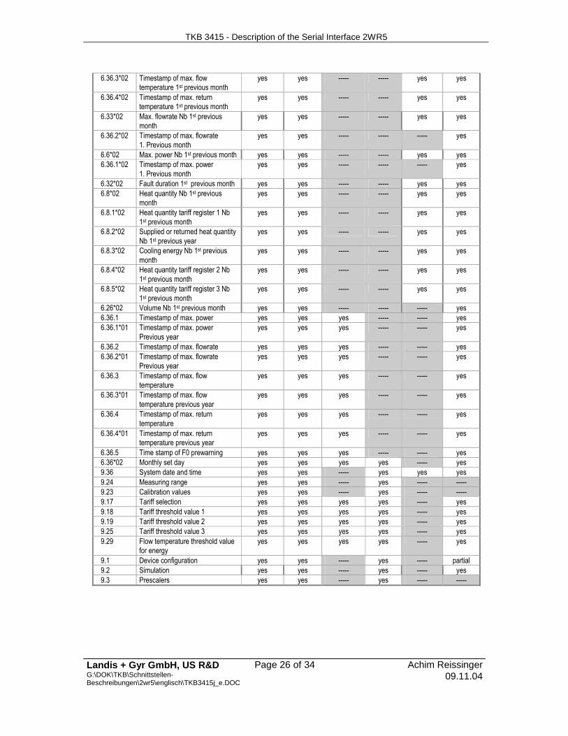
9.2 Table 4: Code numbers for data telegrams 2WR5 - Overview
Output through
Code Meaning CL module...modem module
optical interface
...M-bus ...LCD
Optional data
Mandatory data
Eb data
6.8 Heat quantity Nb yes yes yes yes yes yes 6.26 Volume Nb yes yes yes yes yes yes 9.21 K number yes yes yes yes yes yes 6.4 Power Nb yes yes ----- ----- yes yes 6.27 Flowrate Nb yes yes ----- ----- yes yes 6.29 Temperature flow Nb yes yes ----- ----- yes yes 6.28 Temperature return Nb yes yes ----- ----- yes yes 6.30 Temperature difference Nb yes yes ----- ----- yes yes 6.26*01 Volume Nb previous year yes yes yes ----- yes yes 6.8*01 Heat quantity Nb previous year yes yes yes ----- yes yes F Fault display yes yes yes yes recoded yes 9.20 Device number yes yes yes yes yes yes 6.35 Measuring period yes yes yes yes yes yes 6.6 Max. power Nb yes yes yes yes yes yes 6.6*01 Max. power Nb previous year yes yes yes yes yes yes 6.33 Max. flowrate Nb yes yes yes yes yes yes 9.4 Max. temperatures Nb yes yes yes yes yes yes 6.31 Operating duration yes yes yes yes yes yes 6.32 Fault duration yes yes yes yes yes yes 9.22 Mounting location yes yes yes yes yes yes 9.6 M-bus address yes yes yes yes yes yes 9.7 Expansion yes yes yes yes yes yes 6.32*01 Fault duration previous year yes yes yes yes yes yes 6.36 Set day yes yes yes yes yes yes 6.33*01 Max. flowrate Nb previous year yes yes yes yes yes yes 6.8.1 Heat quantity tariff register 1 Nb yes yes yes yes ----- yes 6.8.2 Supplied or returned heat quantity
Nb yes yes yes yes yes yes
6.8.3 Cold energy Nb yes yes yes yes yes yes 6.8.4 Heat quantity tariff register 2 Nb yes yes yes yes yes yes 6.8.5 Heat quantity tariff register 3 Nb yes yes yes yes yes yes 6.8.1*01 Heat quantity tariff register 1 Nb
previous year yes yes yes yes yes yes
6.8.2*01 Supplied or returned heat quantity Nb previous year
yes yes yes yes yes yes
6.8.3*01 Cold energy Nb previous year yes yes yes yes yes yes 6.8.4*01 Heat quantity tariff register 2 Nb
previous year yes yes yes yes yes yes
6.8.5*01 Heat quantity tariff register 3 Nb previous year
yes yes yes yes yes yes
9.4*01 Max. temperatures Nb previous year
yes yes yes ----- ----- yes
9.4*02 Max. temperatures Nb 1. Previous month
yes yes ----- ----- ----- yes
TKB 3415 - Description of the Serial Interface 2WR5
Landis + Gyr GmbH, US R&D Page 26 of 34 Achim Reissinger G:\DOK\TKB\Schnittstellen-Beschreibungen\2wr5\englisch\TKB3415j_e.DOC
09.11.04
6.36.3*02 Timestamp of max. flow
temperature 1st previous month yes yes ----- ----- yes yes
6.36.4*02 Timestamp of max. return temperature 1st previous month
yes yes ----- ----- yes yes
6.33*02 Max. flowrate Nb 1st previous month
yes yes ----- ----- yes yes
6.36.2*02 Timestamp of max. flowrate 1. Previous month
yes yes ----- ----- ----- yes
6.6*02 Max. power Nb 1st previous month yes yes ----- ----- yes yes 6.36.1*02 Timestamp of max. power
1. Previous month yes yes ----- ----- ----- yes
6.32*02 Fault duration 1st previous month yes yes ----- ----- yes yes 6.8*02 Heat quantity Nb 1st previous
month yes yes ----- ----- yes yes
6.8.1*02 Heat quantity tariff register 1 Nb 1st previous month
yes yes ----- ----- yes yes
6.8.2*02 Supplied or returned heat quantity Nb 1st previous year
yes yes ----- ----- yes yes
6.8.3*02 Cooling energy Nb 1st previous month
yes yes ----- ----- yes yes
6.8.4*02 Heat quantity tariff register 2 Nb 1st previous month
yes yes ----- ----- yes yes
6.8.5*02 Heat quantity tariff register 3 Nb 1st previous month
yes yes ----- ----- yes yes
6.26*02 Volume Nb 1st previous month yes yes ----- ----- ----- yes 6.36.1 Timestamp of max. power yes yes yes ----- ----- yes 6.36.1*01 Timestamp of max. power
Previous year yes yes yes ----- ----- yes
6.36.2 Timestamp of max. flowrate yes yes yes ----- ----- yes 6.36.2*01 Timestamp of max. flowrate
Previous year yes yes yes ----- ----- yes
6.36.3 Timestamp of max. flow temperature
yes yes yes ----- ----- yes
6.36.3*01 Timestamp of max. flow temperature previous year
yes yes yes ----- ----- yes
6.36.4 Timestamp of max. return temperature
yes yes yes ----- ----- yes
6.36.4*01 Timestamp of max. return temperature previous year
yes yes yes ----- ----- yes
6.36.5 Time stamp of F0 prewarning yes yes yes ----- ----- yes 6.36*02 Monthly set day yes yes yes yes ----- yes 9.36 System date and time yes yes ----- yes yes yes 9.24 Measuring range yes yes ----- yes ----- ----- 9.23 Calibration values yes yes ----- yes ----- ----- 9.17 Tariff selection yes yes yes yes ----- yes 9.18 Tariff threshold value 1 yes yes yes yes ----- yes 9.19 Tariff threshold value 2 yes yes yes yes ----- yes 9.25 Tariff threshold value 3 yes yes yes yes ----- yes 9.29 Flow temperature threshold value
for energy yes yes yes yes ----- yes
9.1 Device configuration yes yes ----- yes ----- partial 9.2 Simulation yes yes ----- yes ----- yes 9.3 Prescalers yes yes ----- yes ----- -----

TKB 3415 - Description of the Serial Interface 2WR5
Landis + Gyr GmbH, US R&D Page 27 of 34 Achim Reissinger G:\DOK\TKB\Schnittstellen-Beschreibungen\2wr5\englisch\TKB3415j_e.DOC
09.11.04
9.5 Measuring path parameters 1 yes yes ----- yes ----- ----- 9.5*01 Measuring path parameters 2 yes yes ----- yes ----- ----- 9.5*02 Parameter for fast pulses yes yes ----- yes ----- partial 9.5*03 Tariff switchover time yes yes ----- yes ----- yes 9.15 Supplied heat quantity Nb yes yes ----- yes ----- yes 9.16 Returned heat quantity Nb yes yes ----- yes ----- yes 9.15*01 Supplied heat quantity Nb
previous year yes yes ----- yes ----- yes
9.16*01 Returned heat quantity Nb previous year
yes yes ----- yes ----- yes
9.4*xx Max. temperatures Nb previous months
yes yes ----- ----- ----- yes
6.36.3*xx Timestamp of max. flow temperature previous months
yes yes ----- ----- ----- yes
6.36.4*xx Timestamp of max. return temperature previous months
yes yes ----- ----- ----- yes
6.33*xx Max. flowrate Nb previous months yes yes ----- ----- ----- yes 6.36.2*xx Timestamp of max. flowrate
Previous months yes yes ----- ----- ----- yes
6.6*xx Max. power Nb yes yes ----- ----- ----- yes 6.36.1*xx Timestamp of max. power
Previous months yes yes ----- ----- ----- yes
6.32*xx Fault duration previous months yes yes ----- ----- ----- yes 6.8*xx Heat quantity Nb previous months yes yes ----- ----- ----- yes 6.8.1*xx Heat quantity tariff register 1 Nb
previous months yes yes ----- ----- ----- yes
6.8.2*xx Supplied or returned heat quantity Nb previous months
yes yes ----- ----- ----- yes
6.8.3*xx Cold energy Nb previous months yes yes ----- ----- ----- yes 6.8.4*xx Heat quantity tariff register 2 Nb
previous months yes yes ----- ----- ----- yes
6.8.5*xx Heat quantity tariff register 3 Nb previous months
yes yes ----- ----- ----- yes
6.26*xx Volume Nb previous months yes yes ----- ----- ----- yes 9.8 Heat quantity Pb ----- ----- ----- yes ----- Pb-W 9.26 Volume Pb ----- ----- ----- yes ----- Pb-V 9.27 Flowrate Pb ----- ----- ----- yes ----- Pb-Q 9.28 Temperature return Pb ----- ----- ----- yes ----- Pb-TR 9.30 Temperature difference Pb ----- ----- ----- yes ----- Pb-T 0.0 K number acc. to EN1434-3 yes yes yes ----- ----- yes

TKB 3415 - Description of the Serial Interface 2WR5
Landis + Gyr GmbH, US R&D Page 28 of 34 Achim Reissinger G:\DOK\TKB\Schnittstellen-Beschreibungen\2wr5\englisch\TKB3415j_e.DOC
09.11.04
9.3 Table 5: Code numbers for data telegrams 2WR5 - Description
Meaning Code Format Comment Calibration values 9.23 A0&A1&A2&A3
&A4&A5&A6 The calibration values are 3-digit in pseudo hex format. The zero calibrations A1, A3, and A5 are two's complement. The nominal calibrations A0, A2, A4, and A6 are absolute values with a sign bit. The leading characters for A0 is a dummy character.
Supplied or returned heat quantity Nb
6.8.2 1234567*kWh Cumulated supplied or returned Nb heat quantity for tariff acquisition. The dimension and resolution depend on the parameterization of the heat meter. Reset with the "Reset counters" telegram.
Supplied heat quantity Nb
9.15 1234567*kWh Cumulated supplied Nb heat quantity for tariff acquisition. The dimension and resolution depend on the parameterization of the heat meter. Reset with the "Reset counters" telegram.
Supplied or returned heat quantity Nb previous year
6.8.2*01 1234567*kWh Supplied or returned Nb heat quantity cumulated by the last set day for tariff acquisition. The dimension and resolution depend on the parameterization of the heat meter. Reset with the "Reset counters" telegram.
Supplied or returned heat quantity Nb previous months
6.8.2*xx 1234567*kWh Nb heat quantity cumulated by the last day of the (xx -1)th previous month. The dimension and resolution depend on the parameterization of the heat meter. Reset with the "Reset counters" telegram.
Supplied heat quantity Nb previous year
9.15*01 1234567*kWh Supplied Nb heat quantity cumulated by the last set day for tariff acquisition. The dimension and resolution depend on the parameterization of the heat meter. Reset with the "Reset counters" telegram.
Operating duration 6.31 1234567*D or 1234567*h
Counted days/hours since commissioning or since last reset of the day counter. Leading zeroes are also output. Resetting is possible with the "Reset timers" telegram, which also clears the missing time.
Flowrate Nb 6.27 v123.456*m3ph For negative flowrate: v = "-", otherwise no v. Leading zeroes are also output. In the event of an error (F0, F4...) there will be a null string between the parentheses.
Flowrate Pb 9.27 aaaaa Flowrate, measured in Pb-Q. Pseudo hex two's complement format; 1 digit = 1/2500*m³/h.
Mounting location 9.22 V | R The volume measuring unit can be installed in the flow or in the return branch.
Expansion 9.7 ABCDE Pseudo hex format A.0: 1 = F0 prewarning A.2: 1 = Power-on setting activated (firmware version 2.18 or later)

TKB 3415 - Description of the Serial Interface 2WR5
Landis + Gyr GmbH, US R&D Page 29 of 34 Achim Reissinger G:\DOK\TKB\Schnittstellen-Beschreibungen\2wr5\englisch\TKB3415j_e.DOC
09.11.04
Device configuration 9.1 g&n&t&M&SW&S&FW
All values in pseudo hex format. g = 0: error as basic display; g=1: Heat quantity, etc., as the basic display n = 0: decimal places suppressed; n = 1: decimal places static; n = 2: blinking decimal places t.0: 0= call-up button released; 1= button locked t.1: 0=commissioning lock inactive; 1=commissioning lock active t.2: 0=loop lock inactive; 1=loop lock active M: "-" =without module; "P"=pulse module; "B"=M-bus module or modem module or M-bus combi module; "C"=20mA modul; "K"=CL combi module SW: CV=count volume; CT=count tariff; RI=ready indicator S.0: 0=test seal not set, 1=test seal set; S.1: 0=meas.interval 2s; 1=meas.interval 4s S.2: 0=TR real, 1=TR simulated; S.3: free FW = firmware version, e.g.: 2.03
Device number 9.20 12345678 Pseudo hex numbers. K number acc. to EN1434-3
0.0 12345678 Equivalent to 9.21; pseudo hex numbers.
Cold energy Nb 6.8.3 1234567*kWh Cumulated Nb cold energy with tariff acquisition active. The dimension and resolution depend on the parameterization of the heat meter. Reset with the "Reset counters" telegram.
Cold energy Nb previous year
6.8.3*01 1234567*kWh Nb quantity of cold cumulated by the last set day with tariff acquisition active. The dimension and resolution depend on the parameterization of the heat meter. Reset with the "Reset counters" telegram.
Cold energy Nb previous months
6.8.3*xx 1234567*kWh Nb quantity of cold energy cumulated by the last day of the (xx -1)th previous month with active tariff recording. The dimension and resolution depend on the parameterization of the heat meter. Reset with the "Reset counters" telegram.
Customer number HM 9.21 12345678 Pseudo hex numbers. Power Nb 6.4 v1234.5*kW Leading zeroes are also output.
For negative power: v = "-", otherwise no v. As from measuring range 40m³/h resolution 1kW instead of 0.1kW. In the event of an error (F0, F3...) there will be a null string between the parentheses.
M-bus address 9.6 ppp&ssssssss&S
p = M-bus primary address s = M-bus secondary address (= customer number) S = M-bus status
Max. flowrate Nb 6.33 123.456*m3ph Value positive; leading zeroes are output. Reset is performed with the "Reset maxima" or "Set measuring period" telegrams.
Max. flowrate Nb previous year
6.33*01 123.456*m3ph Max. flowrate since commissioning or last reset of the maxima until the last set day. Value positive; leading zeroes are output. Reset with the "Reset counters" telegram.
Max. flowrate Nb previous months
6.33*xx 123.456*m3ph Max. flowrate in the (xx -1)th previous month. Value positive; leading zeroes are output. Reset with the "Reset counters" telegram.
Max. power Nb 6.6 1234.5*kW Value positive; leading zeroes are output. As from measuring range 40m³/h resolution 1kW instead of 0.1kW. Reset is performed with the "Reset maxima" or "Set measuring period" telegrams.

TKB 3415 - Description of the Serial Interface 2WR5
Landis + Gyr GmbH, US R&D Page 30 of 34 Achim Reissinger G:\DOK\TKB\Schnittstellen-Beschreibungen\2wr5\englisch\TKB3415j_e.DOC
09.11.04
Max. power previous year
6.6*01 1234.5*kW Max. power since commissioning or last reset of the maxima until the last set day. Value positive; leading zeroes are output. As from measuring range 40m³/h resolution 1kW instead of 0.1kW. Reset with the "Reset counters" telegram.
Max. power Nb 6.6*xx 1234.5*kW Max. power in the (xx -1)th previous month. Value positive; leading zeroes are output. As from measuring range 40m³/h resolution 1kW instead of 0.1kW. Reset with the "Reset counters" telegram.
Max. temperatures 9.4 vvv*C&rrr*C vvv = max. flow temperature; rrr = max. return temperature. Value positive; leading zeroes are output. Reset is performed with the "Reset counters" telegram.
Max. temperatures Previous year
9.4*01 vvv*C&rrr*C Max. temperatures since commissioning or last reset of the maxima until the last set day. vvv = max. flow temperature; rrr = max. return temperature. Value positive; leading zeroes are output. Reset is performed with the "Reset counters" telegram.
Max. temperatures Previous months
9.4*xx vvv*C&rrr*C Max. temperatures in the (xx -1)th previous month. vvv = max. flow temperature; rrr = max. return temperature. Value positive; leading zeroes are output. Reset is performed with the "Reset counters" telegram.
Measuring range 9.24 Qnom*m3ph Qnom = 0.6, 1.0, 1.5, 2.5, 3.5, 6, 10, 15, 25, 40 or 60*m3ph. Measuring period 6.35 60*min The measuring period is the time over which the mean values
of the temperatures, power, flowrate are formed for calculating the maxima. Values: 7.5 / 15 / 30 / 60 min; default values = 60 min. The "Set measuring period" telegram automatically resets the maximum values. The temperatures for maximum calculation are not averaged and can only be reset with "Reset counters".
Measuring path parameters 1
9.5 G&SV&SR&DV&DR&DF&S&A&C&K&F
All values in pseudo hex format. Quality(2) & ThresholdV(8) & ThresholdR(8) & DAC_V(2) & DAC_R(2) & DAC_F0(2) & SLZ(5) & WZ(2)/nLZM(2)/n0LZM(1)/SI(1)/EFE(2)/MS(1)/ADW5(1)/EF0(2) & KC(4) & KRZK(4) & FEHL(3). Set runtime ='00' + SLZ + '000' FEHL, Bit 3-0: F7, F_liste, EE_Ausw, EE_fatal; F0, F0-Latch, ULatch, F3; F4, F8, F9, ZRaffer
Measuring path parameters 2
9.5*01 V1&V1Abgl&V2&V2Abgl&U&O&M&A&B&R&MV&MR
All values in pseudo hex format. V1(1)/V1Abgl(1) & V2(2)/V2Abgl(2) & DAC_U(2) & DAC_O(2) & DAC_M(2) & AC(2) & B/C/D/E/H/T/I(7) & Resetzähler(4) & MitV(16) & MitR(16). Values B, D, E: See parameters for I42 and P=xx1
Monthly set day 6.36*02 TT Day for transferring the volume, heat quantity, fault duration, power, and flowrate maximum into the previous month's memory Transfer is performed at 0:00. Default value = 01.mm.yy
Parameter for fast pulses 9.5*02 W&V&L&VO&VR&KT
All values in pseudo hex format. Scaler Heat quantity pulses (6) & Scaler Volume pulses (6) & Pulse length(2)/Maximum value Heat quantity pulses(2)/ Maximum value Volume pulses (2)/Minimum value Heat quantity pulses (2)/Minimum value Volume pulses(2) & VO(6) & VR(6) & KT(3) Description of the pulse parameters: See parameters for P=xx1.
Returned heat quantity Nb
9.16 1234567*kWh Cumulated returned Nb heat quantity for tariff acquisition. The dimension and resolution depend on the parameterization of the heat meter. Reset with the "Reset counters" telegram.

TKB 3415 - Description of the Serial Interface 2WR5
Landis + Gyr GmbH, US R&D Page 31 of 34 Achim Reissinger G:\DOK\TKB\Schnittstellen-Beschreibungen\2wr5\englisch\TKB3415j_e.DOC
09.11.04
Returned heat quantity Nb previous year
9.16*01 1234567*kWh Returned Nb heat quantity cumulated by the last set day for tariff acquisition. The dimension and resolution depend on the parameterization of the heat meter. Reset with the "Reset counters" telegram.
Simulation 9.2 rrrr&vvvv&qqqqq
Simulation values of return, flow temperature and flowrate; in pseudo hex two's complement format. If simulation is not active, a null string will be output.
Set day 6.36 MM-DD Date each year for transferring the volume, heat quantity, fault duration, power, and flowrate maximum into the previous year's memory Transfer is performed at 0:00, i.e. on this day it is already possible to read out the previous year's values.
Fault display F 0 | 3&5&6... Caution: Coded acc. to EN 1434-3. 0 = No error 3 = Internal errors (F3.4.7.8.9.M) 5 = Flowrate error (F_US=F0,F9,F4) 6 = Break V (F1), 7 = Closure V (F5); 8 = Break R (F2); 9 = Closure R (F6)
Fault duration 6.32 1234567*D or 1234567*h
Counted missing days/hours since commissioning or since last reset of the missing time counter. Leading zeroes are also output. Resetting is possible with the "Reset missing time" (for missing time only) and "Reset times" (missing and operating times) telegrams.
Fault duration previous year
6.32*01 1234567*D or 1234567*h
Missing days/hours since commissioning or last reset of the missing time counter until the last set day. Reset with the "Reset counters" telegram.
Fault duration previous months
6.32*xx 1234567*D or 1234567*h
Missing days/hours since commissioning or last reset of the missing time counter until the last day of the (xx -1)th month. Reset with the "Reset counters" telegram.
System time 9.36 yyyy-mm-dd& hh:mm:ss
Internal data and internal time of the heat meter at the time of read-out. Output in ASCII format.
Tariff selection 9.17 a Type of tariff: a 0: Tariff control not activated 1: Reserved 2: Tariff control using current flowrate (threshold) 3: Tariff control using current power (threshold) 4: Tariff control using current return temp. (threshold value) 5: Reserved 6: Tariff control using current return diff. (threshold value) 7: Heat quantity supplied 8: Returned heat quantity 9: Heat / cold meter 10: Tariff time switch 11: Control from M bus
Tariff threshold value 1 9.18 sssss*e Tariff threshold value 1: sssss The number of decimal places or the unit e corresponds to the current measured value. Depending on the type of tariff control, this value determines when the tariff is activated: If the current measured value is less than or equal to threshold value 1, cumulation is not performed into tariff register 1 (heat quantity) (tariff inactive); if it is greater than the threshold value, cumulation is performed into tariff register 1 (tariff active). The heat/cold meter is an exception. Here, if the temperature difference is negative, cumulation is performed into tariff register 1 (cold quantity) if the current measured value is less than or equal to the threshold value. If the temperature difference is positive, cumulation is performed into the heat quantity register (heat quantity). No threshold value 1 is implemented for supply or return heat quantity, tariff switch, and control via M-bus.

TKB 3415 - Description of the Serial Interface 2WR5
Landis + Gyr GmbH, US R&D Page 32 of 34 Achim Reissinger G:\DOK\TKB\Schnittstellen-Beschreibungen\2wr5\englisch\TKB3415j_e.DOC
09.11.04
Tariff threshold value 2 9.19 ttttt*e Tariff threshold value 2: ttttt The number of decimal places or the unit e corresponds to the current measured value. Depending on the type of tariff control, this value determines when the tariff is activated: If the current measured value is less than or equal to threshold value 2, cumulation is not performed into tariff register 2 (heat quantity) (tariff inactive); if it is greater than the threshold value 2, cumulation is performed into tariff register 2 (tariff active). No threshold value 2 is implemented for supply or return heat quantity, heat cold counter, tariff switch, and control via M-bus.
Tariff threshold value 3 9.25 uuuuu*e Tariff threshold value 3: uuuuu The number of decimal places or the unit e corresponds to the current measured value. Depending on the type of tariff control, this value determines when the tariff is activated: If the current measured value is less than or equal to threshold value 3, cumulation is not performed into tariff register 3 (heat quantity) (tariff inactive); if it is greater than the threshold value 3, cumulation is performed into tariff register 3 (tariff active). No threshold value 3 is implemented for supplied or returned heat quantity, heat cold counter, tariff switch, and control via M bus.
Flow temperature threshold value for energy (only for heat/cold meter)
9.29 vvvvv*e Flow temperatur threshold value for energy: vvvvv The number of decimal places or the unit e corresponds to the current measured value. At the heat/cold meter, if the temperature difference is negative, cumulation is performed into tariff register 1 (cold quantity) if the current measured value is less than or equal to the threshold value for cold energy. If the temperature difference is positive, cumulation is performed into the heat quantity register (heat quantity) if the current measured value is higher than the threshold value for energy.
Tariff switchover time 9.5*03 hhmmt&HHMMT
Tariff switchover point 1: hhmmt Tariff switchover point 2: HHMMT hh, HH: Hour mm, MM: Minute t, T: Number of tariff register (0, 1, 2, or 3) Values are only displayed if the tariff switch (tariff type 10) is active.
Temperature return Nb 6.28 v123*C For negative temperature: v = "-", otherwise no v. Leading zeroes are also output. In the event of an error (F0, F3...) there will be a null string between the parentheses.
Temperature return Pb 9.28 aaaaa Return temperature, measured in Pb-T or Pb-W. Pseudo hex two's complement format; 1 digit = 1/3200*°C.
Temperature flow Nb 6.29 v123*C For negative temperature: v = "-", otherwise no v. Leading zeroes are also output. In the event of an error (F0, F3...) there will be a null string between the parentheses.
Temperature difference Nb
6.30 v123.4*C For negative temperature difference: v = "-", otherwise no v. Leading zeroes are also output. In the event of an error (F0, F3...) there will be a null string between the parentheses.
Temperature difference Pb
9.30 aaaaa Temperature difference, measured in Pb-T or Pb-W. Pseudo hex two's complement format; 1 digit = 1/3200*°C.
Volume Nb 6.26 12345.67*m3 Cumulated Nb volume. As of measuring range 25m³/h resolution 0.1m³ instead of 0.01m³. Leading zeroes are also output. Reset with the "Reset counters" telegram.

TKB 3415 - Description of the Serial Interface 2WR5
Landis + Gyr GmbH, US R&D Page 33 of 34 Achim Reissinger G:\DOK\TKB\Schnittstellen-Beschreibungen\2wr5\englisch\TKB3415j_e.DOC
09.11.04
Volume Nb previous year 6.26*01 12345.67*m3 Nb volume cumulated by the last set day. As of measuring range 25m³/h resolution 0.1m³ instead of 0.01m³. Reset with the "Reset counters" telegram.
Volume Nb previous months
6.26*xx 12345.67*m3 Nb volume cumulated by the last day of the (xx -1)the previous month. As of measuring range 25m³/h resolution 0.1m³ instead of 0.01m³. Reset with the "Reset counters" telegram.
Volume Pb 9.26 1.23456*m3 Cumulated volume in Pb-V, or simulated volume (2.0 m³) in Pb-W. Leading zeroes are also output.
Prescalers 9.3 nUS&PhiV& PhiW&W0
n = number of US measurements (in ASCII format); PhiV, PhiW, W0 = prescaler (in pseudo hex two's complement format). The basic values of the prescaler depend on the measuring range, measuring interval, and firmware! PhiW and W0 are only defined in Nb. Significance of PhiV in Pb: 1ml/307.2
Heat quantity Nb 6.8 1234567*kWh Cumulated Nb heat quantity. The dimension and resolution depend on the parameterization of the heat meter. Reset with the "Reset counters" telegram.
Heat quantity tariff register Nb
6.8.1 1234567*kWh Cumulated Nb heat quantity with tariff acquisition active. The dimension and resolution depend on the parameterization of the heat meter. Reset with the "Reset counters" telegram.
Heat quantity Nb previous year
6.8*01 1234567*kWh Nb heat quantity cumulated by the last set day. The dimension and resolution depend on the parameterization of the heat meter. Reset with the "Reset counters" telegram.
Heat quantity Nb previous months
6.8*xx 1234567*kWh Nb heat quantity cumulated by the last day of the (xx -1)the previous month. The dimension and resolution depend on the parameterization of the heat meter. Reset with the "Reset counters" telegram.
Heat quantity tariff register 1 Nb previous year
6.8.1*01 1234567*kWh Nb heat quantity cumulated by the last set day with tariff acquisition active in tariff register 1. The dimension and resolution depend on the parameterization of the heat meter. Reset with the "Reset counters" telegram.
Heat quantity tariff register 1 Nb previous months
6.8.1*xx 1234567*kWh Nb heat quantity cumulated by the last day of the (xx -1)th previous month in tariff register 1. The dimension and resolution depend on the parameterization of the heat meter. Reset with the "Reset counters" telegram.
Heat quantity tariff register 2 Nb previous year
6.8.4*01 1234567*kWh Nb heat quantity cumulated by the last set day with tariff acquisition active in tariff register 1. The dimension and resolution depend on the parameterization of the heat meter. Reset with the "Reset counters" telegram.
Heat quantity tariff register 2 Nb previous months
6.8.4*xx 1234567*kWh Nb heat quantity cumulated by the last day of the (xx -1)th previous month in tariff register 2. The dimension and resolution depend on the parameterization of the heat meter. Reset with the "Reset counters" telegram.
Heat quantity tariff register 3 Nb previous year
6.8.5*01 1234567*kWh Nb heat quantity cumulated by the last set day with tariff acquisition active in tariff register 1. The dimension and resolution depend on the parameterization of the heat meter. Reset with the "Reset counters" telegram.

TKB 3415 - Description of the Serial Interface 2WR5
Landis + Gyr GmbH, US R&D Page 34 of 34 Achim Reissinger G:\DOK\TKB\Schnittstellen-Beschreibungen\2wr5\englisch\TKB3415j_e.DOC
09.11.04
Heat quantity tariff register 3 Nb previous months
6.8.5*xx 1234567*kWh Nb heat quantity cumulated by the last day of the (xx -1)th previous month in tariff register 3. The dimension and resolution depend on the parameterization of the heat meter. Reset with the "Reset counters" telegram.
Heat quantity Pb 9.8 1234.56*kWh Cumulated heat quantity in Pb-W. The simulated volume, 2.0 m3 is output under 9.26.
Time stamp 6.36.x*yy yyyy-mm-dd Time stamp for extreme values in monthly values and F0 prewarning