Embed Size (px)
Citation preview
T50 / T70 / T90O
pera
ting
Inst
ruct
ions Titration Excellence


Table of Contents
Introduction1 9
Safety Notes2 10
Definition of Signal Warnings and Symbols2.1 10Product Specific Safety Notes2.2 10
Description of Functions3 12
Layout of the Terminal3.1 12Operating the Touchscreen3.2 12The Homescreen3.3 12The User Interface3.4 12Entering Data in the User Interface.3.4.1 13Shortcuts and Direct Shortcuts3.4.2 13The Start Analysis Dialog 3.4.3 14The online screen for GT Titrations3.4.4 14The online screen for KF Titrations3.4.5 15
Setup4 18
Chemicals4.1 18Titrants4.1.1 19Auxiliary reagents4.1.2 20Calibration standards4.1.3 20Concentration and titer standards4.1.4 22Substances4.1.5 22Hardware4.2 23Sensors4.2.1 23Sensor calibration and sensor test4.2.1.1 27Value ranges from sensor measuring units and control band4.2.1.2 29Pumps4.2.2 29Peripherals4.2.3 30Balance4.2.3.1 30Barcode reader4.2.3.2 31USB-Stick4.2.3.3 31Printer4.2.3.4 31PC settings4.2.3.5 33Network settings4.2.3.6 34Fingerprint reader4.2.3.7 34LevelSens4.2.3.8 35TBox4.2.3.9 35Titration stands4.2.4 35Manual stand4.2.4.1 36Auto stand4.2.4.2 36External stand4.2.4.3 37Rondolino TTL4.2.4.4 37Stromboli TTL4.2.4.5 37InMotion4.2.4.6 38Rondo604.2.4.7 39KF stand4.2.4.8 39Auxiliary instruments4.2.5 40Homogenizer4.2.6 41Liquid Handler4.2.7 41User settings4.3 42Language4.3.1 42Screen4.3.2 42
Table of Contents 3

Beep4.3.3 42Shortcuts4.3.4 43Keyboards4.3.5 43Global settings4.4 43System4.4.1 43User Management4.4.2 44Analysis and resources behavior4.4.3 46Solvent Control4.4.4 49Values4.5 50Blanks4.5.1 51Auxiliary values4.5.2 51Maintenance & Service4.6 51MT service4.6.1 52Import/Export4.6.2 52Reset to factory settings4.6.3 53Titrator firmware history4.6.4 53Board firmware4.6.5 53Terminal4.6.6 53Board data4.6.7 53Drives4.6.8 53Burettes4.6.9 53Upgrade4.6.10 53Update4.6.11 53Delete Mettler method template4.6.12 53
Manual operations5 54
Stirrer5.1 54Sensor5.2 55Temperature sensor5.2.1 55Potentiometric Sensor5.2.2 56Polarized sensor5.2.3 57Conductivity sensor5.2.4 57Burette5.3 58Rinse burette5.3.1 58Rinse multiple burettes5.3.2 59Dispense5.3.3 59Manual titration5.3.4 60Pump5.4 62Auxiliary instrument5.5 63Sample changer5.6 65
Methods6 67
METTLER TOLEDO Methods6.1 68Creating Methods6.2 69Method Templates6.2.1 70Modifying or Deleting Methods6.3 71Starting Methods6.4 71Stopping Methods6.5 72Suspending an ongoing analysis by the user6.5.1 72Interrupting an ongoing analysis by the titrator6.5.2 72Method Syntax – Rules for Establishing a Method6.6 73Types and Possible Number of Loops6.6.1 73Sample Loops6.6.2 73
Table of Contents4

Inserting and Deleting Loops6.6.3 74Overview of method functions6.7 74Possible Number of Method functions6.7.1 76Method functions6.8 77Title 6.8.1 77Sample 6.8.2 78Sample (titer) 6.8.3 79Sample (calibration)6.8.4 79pH sensor test6.8.4.1 80Sample (KF)6.8.5 81Titration stand6.8.6 85Line Rinse6.8.7 86Liquid Handling6.8.8 86Mix time6.8.9 89Rinse6.8.10 89Conditioning6.8.11 90Pump6.8.12 90Park6.8.13 91Stir6.8.14 91Dispense (normal) 6.8.15 92Sync6.8.16 92Methods with subfunctions6.8.17 93Measure (normal) 6.8.17.1 93Measure (MVT) 6.8.17.2 96Titration (EQP) 6.8.17.3 97Titration (EP)6.8.17.4 101Application Modes6.8.17.5 104Titration (2-phase)6.8.17.6 104Titration (LearnEQP) 6.8.17.7 107Titration (KF Vol)6.8.17.8 108Stating6.8.17.9 109Dispense (controlled)6.8.17.10 112Calculation6.8.18 114End of sample6.8.19 116Titer6.8.20 116Calibration6.8.21 116Auxiliary value6.8.22 117Blank6.8.23 118Auxiliary instrument6.8.24 119Control type: Output 24V6.8.24.1 119Control type: Stirrer6.8.24.2 119Control type: Out TTL (Single pin)6.8.24.3 119Control type: Input TTL (single pin) 6.8.24.4 120Control type: TTL (multipin)6.8.24.5 120Control type: RS-2326.8.24.6 121Instruction6.8.25 122Drain6.8.26 123Record6.8.27 123Drift determination6.8.28 125Homogenizer6.8.29 125Standby6.8.30 126Hidden method functions6.8.31 126Method functions Within a Loop6.9 126Method functions Outside of a Loop6.10 127
Table of Contents 5
Series Templates7 129
Sample Series7.1 129Series Sequence (T90)7.2 130Free Sample Series7.3 130Sample or Standard Parameters7.4 130
Analysis Sequences8 133
Starting an Analysis8.1 133Analysis Sequence Steps8.2 134GT Analysis sequence8.2.1 135KF Analysis sequence8.2.2 136Series analyses with the "Stromboli" oven sample changer8.2.2.1 138External extraction8.2.2.2 139Switching between determination types8.2.2.3 139Analysis records8.2.2.4 140Replacing the titrant8.2.2.5 140
Analysis Data9 141
Titrator Evaluation Procedure10 142
Standard Evaluation Procedure10.1 142Minimum / Maximum10.2 142Segmented Evaluation10.3 143Asymmetric10.4 143
Evaluate and calculate11 145
Indexing of method functions11.1 145Formulas11.2 146Using analysis data in formulas11.2.1 146Sample formulas11.2.2 148Constants within a Content Calculation11.2.3 148Mathematical functions and operators11.2.4 149Naming Conventions for Using Analysis Data in Calculations11.3 150Explanatory examples11.4 158Titration method function11.4.1 158Stating method function11.4.2 160
Results12 162
Results proposal list for GT12.1 162Result proposal lists for Karl Fischer titration12.2 163Internal calculations12.2.1 165All results12.3 165Add result12.4 165Statistics12.5 166Outlier test12.5.1 166Recalculate12.6 167Samples12.7 168Reevaluate12.8 168Undo changes12.9 168Delete all results12.10 168Access to buffer12.11 169
Table of Contents6

Appendix13 170
Predefined calibration standards for pH sensors13.1 170Temperature related values13.1.1 170METTLER TOLEDO13.1.1.1 170DIN / NIST13.1.1.2 171MERCK13.1.1.3 171FLUKA13.1.1.4 172FISHER13.1.1.5 173JIS / JJG13.1.1.6 173Predefined calibration standards for conductivity sensors13.2 174Temperature related values13.2.1 174REAGECON13.2.1.1 174METTLER TOLEDO13.2.1.2 176Karl Fischer Water Determination - Measuring Principle13.3 176
Index 177
Table of Contents 7


1 IntroductionSimple, efficient and reliable!
The instruments in METTLER TOLEDO's Titration Excellence Line are modern, modular titrators for use in a widerange of applications. They can be used in quality control as well as research and development. Due to thiswide array of applications, you can enjoy the highest level of function.
The titrators in the Titration Excellence Line (T50, T70 and T90) combine simple, easy-to-use functions withmaximum flexibility and outstanding analytical efficiency. Rapid titrant change is made easy thanks to a newprocedure that detects titrant automatically (Burette Plug & Play – PnP). The titrator automatically recognizesthe titrant needed without the need for any action by the user. Even installing sample changers and additionaldosing units makes manual adjustments superfluous.
In addition to general titration, the T70 and T90 models in the Titration Excellence Line also offer the option ofvolumetric water content determination using the Karl Fischer method.
The various options for titrator operation using LabX PC software are explained in the integrated help system ofLabX.
The enclosed separate installation information describes all of the steps necessary to install and begin operating your Titration Excellence device. Afterwards, a separate "Quick Guide" guides you through the first titrationprocess using a practical example. If you have any additional questions, METTLER TOLEDO is always availableto assist you.
9Introduction
2 Safety Notes
2.1 Definition of Signal Warnings and SymbolsSafety notes are marked with signal words and warning symbols. These show safety issues and warnings.Ignoring the safety notes may lead to personal injury, damage to the instrument, malfunctions and false results.
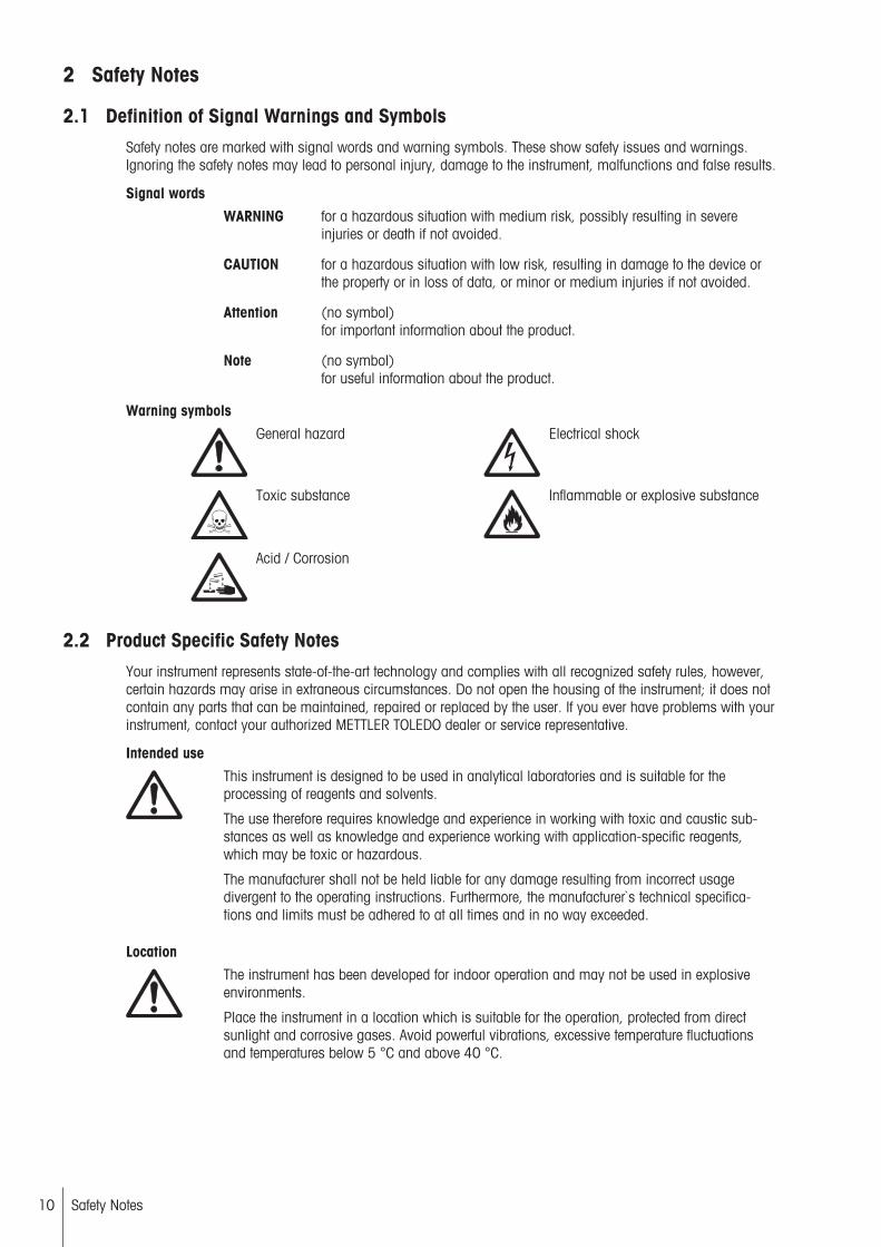
Signal words
WARNING for a hazardous situation with medium risk, possibly resulting in severeinjuries or death if not avoided.
CAUTION for a hazardous situation with low risk, resulting in damage to the device orthe property or in loss of data, or minor or medium injuries if not avoided.
Attention (no symbol)for important information about the product.
Note (no symbol)for useful information about the product.
Warning symbols
General hazard Electrical shock
Toxic substance Inflammable or explosive substance
Acid / Corrosion
2.2 Product Specific Safety NotesYour instrument represents state-of-the-art technology and complies with all recognized safety rules, however,certain hazards may arise in extraneous circumstances. Do not open the housing of the instrument; it does notcontain any parts that can be maintained, repaired or replaced by the user. If you ever have problems with yourinstrument, contact your authorized METTLER TOLEDO dealer or service representative.
Intended use
This instrument is designed to be used in analytical laboratories and is suitable for theprocessing of reagents and solvents.
The use therefore requires knowledge and experience in working with toxic and caustic substances as well as knowledge and experience working with application-specific reagents,which may be toxic or hazardous.
The manufacturer shall not be held liable for any damage resulting from incorrect usagedivergent to the operating instructions. Furthermore, the manufacturer`s technical specifications and limits must be adhered to at all times and in no way exceeded.
Location
The instrument has been developed for indoor operation and may not be used in explosiveenvironments.
Place the instrument in a location which is suitable for the operation, protected from directsunlight and corrosive gases. Avoid powerful vibrations, excessive temperature fluctuationsand temperatures below 5 °C and above 40 °C.
10 Safety Notes
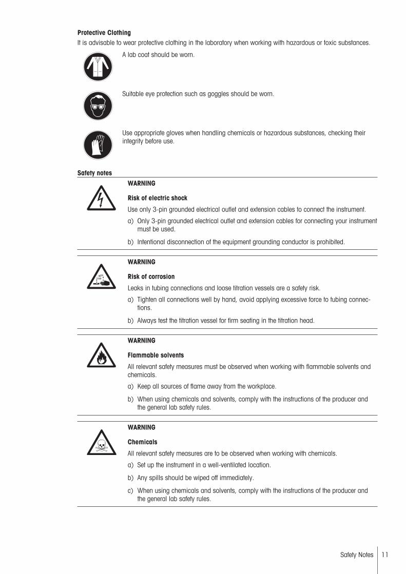
Protective ClothingIt is advisable to wear protective clothing in the laboratory when working with hazardous or toxic substances.
A lab coat should be worn.
Suitable eye protection such as goggles should be worn.
Use appropriate gloves when handling chemicals or hazardous substances, checking theirintegrity before use.
Safety notes WARNING
Risk of electric shock
Use only 3-pin grounded electrical outlet and extension cables to connect the instrument.
a) Only 3-pin grounded electrical outlet and extension cables for connecting your instrumentmust be used.
b) Intentional disconnection of the equipment grounding conductor is prohibited.
WARNING
Risk of corrosion
Leaks in tubing connections and loose titration vessels are a safety risk.
a) Tighten all connections well by hand, avoid applying excessive force to tubing connections.
b) Always test the titration vessel for firm seating in the titration head.
WARNING
Flammable solvents
All relevant safety measures must be observed when working with flammable solvents andchemicals.
a) Keep all sources of flame away from the workplace.
b) When using chemicals and solvents, comply with the instructions of the producer andthe general lab safety rules.
WARNING
Chemicals
All relevant safety measures are to be observed when working with chemicals.
a) Set up the instrument in a well-ventilated location.
b) Any spills should be wiped off immediately.
c) When using chemicals and solvents, comply with the instructions of the producer andthe general lab safety rules.
11Safety Notes
3 Description of Functions
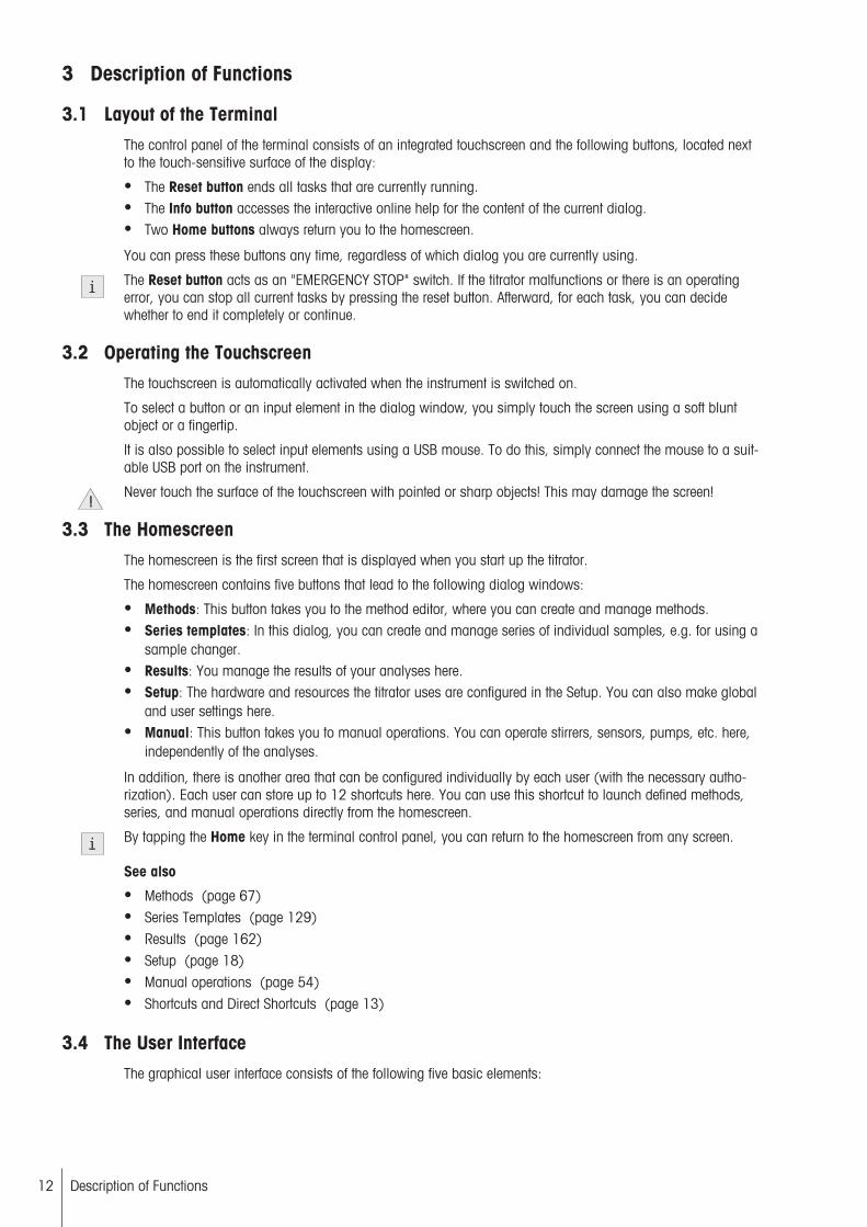
3.1 Layout of the TerminalThe control panel of the terminal consists of an integrated touchscreen and the following buttons, located nextto the touch-sensitive surface of the display:
● The Reset button ends all tasks that are currently running.● The Info button accesses the interactive online help for the content of the current dialog.● Two Home buttons always return you to the homescreen.
You can press these buttons any time, regardless of which dialog you are currently using.
The Reset button acts as an "EMERGENCY STOP" switch. If the titrator malfunctions or there is an operatingerror, you can stop all current tasks by pressing the reset button. Afterward, for each task, you can decidewhether to end it completely or continue.
3.2 Operating the TouchscreenThe touchscreen is automatically activated when the instrument is switched on.
To select a button or an input element in the dialog window, you simply touch the screen using a soft bluntobject or a fingertip.
It is also possible to select input elements using a USB mouse. To do this, simply connect the mouse to a suitable USB port on the instrument.
Never touch the surface of the touchscreen with pointed or sharp objects! This may damage the screen!
3.3 The HomescreenThe homescreen is the first screen that is displayed when you start up the titrator.
The homescreen contains five buttons that lead to the following dialog windows:
● Methods: This button takes you to the method editor, where you can create and manage methods.● Series templates: In this dialog, you can create and manage series of individual samples, e.g. for using a
sample changer.● Results: You manage the results of your analyses here.● Setup: The hardware and resources the titrator uses are configured in the Setup. You can also make global
and user settings here.● Manual: This button takes you to manual operations. You can operate stirrers, sensors, pumps, etc. here,
independently of the analyses.
In addition, there is another area that can be configured individually by each user (with the necessary authorization). Each user can store up to 12 shortcuts here. You can use this shortcut to launch defined methods,series, and manual operations directly from the homescreen.
By tapping the Home key in the terminal control panel, you can return to the homescreen from any screen.
See also
● Methods (page 67)● Series Templates (page 129)● Results (page 162)● Setup (page 18)● Manual operations (page 54)● Shortcuts and Direct Shortcuts (page 13)
3.4 The User InterfaceThe graphical user interface consists of the following five basic elements:
12 Description of Functions
● The title bar at the top of the display specifies the name of the current dialog.● In the top right-hand corner, the Tasks button informs you which processes are currently running. You use
Tasks to access a Tasks dialog that displays an overview of all running tasks. From the Tasks dialog youcan navigate to any process that is currently running.
● The navigation bar, located below the title bar, specifies the path to the current dialog.● The scroll bar on the right-hand side of the screen becomes visible if the content of the screen extends
beyond the viewable area. If this occurs, use either the arrows or the area in between them to move theviewable area of the screen up or down.
● Five buttons are located at the bottom of the screen. The function of these buttons varies and depends onthe context of the current dialog.
3.4.1 Entering Data in the User Interface.
There are different types of input fields in the user interface. They allow you to enter data or select data from alist. Input fields can also be deactivated and their contents are then displayed as information only and cannotbe changed in the corresponding dialog.
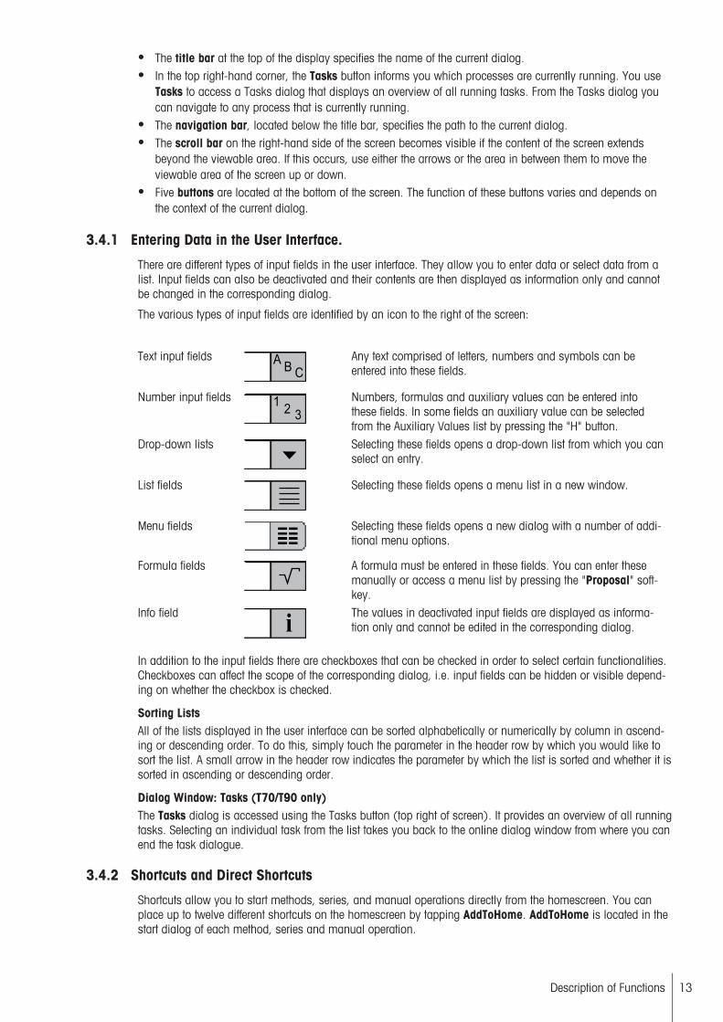
The various types of input fields are identified by an icon to the right of the screen:
Text input fields A
BC
Any text comprised of letters, numbers and symbols can beentered into these fields.
Number input fields 123
Numbers, formulas and auxiliary values can be entered intothese fields. In some fields an auxiliary value can be selectedfrom the Auxiliary Values list by pressing the "H" button.
Drop-down lists Selecting these fields opens a drop-down list from which you canselect an entry.
List fields Selecting these fields opens a menu list in a new window.
Menu fields Selecting these fields opens a new dialog with a number of additional menu options.
Formula fields A formula must be entered in these fields. You can enter thesemanually or access a menu list by pressing the "Proposal" softkey.
Info fieldi
The values in deactivated input fields are displayed as information only and cannot be edited in the corresponding dialog.
In addition to the input fields there are checkboxes that can be checked in order to select certain functionalities.Checkboxes can affect the scope of the corresponding dialog, i.e. input fields can be hidden or visible depending on whether the checkbox is checked.
Sorting ListsAll of the lists displayed in the user interface can be sorted alphabetically or numerically by column in ascending or descending order. To do this, simply touch the parameter in the header row by which you would like tosort the list. A small arrow in the header row indicates the parameter by which the list is sorted and whether it issorted in ascending or descending order.
Dialog Window: Tasks (T70/T90 only)The Tasks dialog is accessed using the Tasks button (top right of screen). It provides an overview of all runningtasks. Selecting an individual task from the list takes you back to the online dialog window from where you canend the task dialogue.
3.4.2 Shortcuts and Direct Shortcuts
Shortcuts allow you to start methods, series, and manual operations directly from the homescreen. You canplace up to twelve different shortcuts on the homescreen by tapping AddToHome. AddToHome is located in thestart dialog of each method, series and manual operation.
13Description of Functions

Shortcuts are user-specific, i.e. each individual user can create a maximum of twelve shortcuts for the tasksthey personally conduct the most with the titrator.
The titrator supports two types of shortcuts. Direct shortcuts which, when selected, start the task immediatelywithout warning (only if the other settings allow this), and normal shortcuts which take you to the corresponding start dialog from which you can start the task.
Shortcuts for methods, series or manual operations that take youto the corresponding start dialog.
Shortcuts for methods, series or manual operations with integrated reference symbols in the icon that start the corresponding taskwhen selected provided the other settings allow for it.
Shortcuts are managed in Setup > User settings. Here you can delete or modify shortcuts, or change theirposition on the homescreen (see "User settings: Shortcuts").
Tasks started using the shortcuts can begin immediately without warning. Therefore, always make sure that alltubes are connected to suitable vessels prior to using a shortcut.
● Once the maximum number of shortcuts (12) has been created in the Homescreen, the button AddToHomeis deactivated in the start dialog for methods, series and manual operations.
3.4.3 The Start Analysis Dialog
An analysis - whether it be a single or multiple determination - can be started on the titrator in several differentways:
● By choosing Start from the method editor.● By choosing Start from the Homescreen.● By using a shortcut (or direct shortcut) from the Homescreen.● By choosing Start from the screen Series.● By choosing Calibration or Titer from the screen Setup dialog (in order to start a calibration or titer deter
mination).
The screen Start analysis is always the first screento appear once you choose Start, Calibration, Sensor testor Titer or the corresponding shortcut.
● When a direct shortcut is activated, the screen Start analysis does not appear and the respective methodstarts immediately, provided that the other settings allow this.
● The parameters for the previously used method or series appear in the screen Start analysis, so that thesame method can immediately be started again.
● Of course, all of the settings can also be adjusted prior to pressing Start. The type and number of settingsdisplayed in the screenStart analysis depends on the type of analysis to be started and the resources used.
3.4.4 The online screen for GT Titrations
The Online screen is displayed when an analysis or manual operation is being performed.
The method ID of the current method or the type of manual operation is displayed in the title bar. In the navigation bar below, the sample index, e.g. displayed as "Sample 2/5" (second of a total of five samples) and loopindex, displayed as "Loop 1/3" (first of three loops) are shown. (The Loop index is only displayed if the methodactually contains more than on loop). The navigation path is displayed in the navigation bar while a manualoperation is being performed. The remainder of the online dialog is divided into a graphical area (left) and adata area (right). During a titration or measurement, the graphical area displays the measurement curve.
The Online dialog for a titration of type GT contains the following buttons:
14 Description of Functions
ResultsThe Results button is used to display the results and statistics for the analyzed samples after the analysis.
AxesYou can select the units for the horizontal and vertical axes from a list.
Measured valuesAs an alternative to the online dialog, you can use the Measured values button to display a table of measuredvalues during the analysis.
SamplesChoose Samples to change sample and series data.
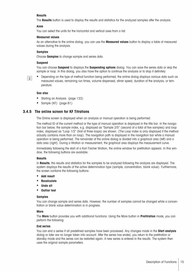
SuspendYou can choose Suspend to displays the Suspending options dialog. You can save the series data or skip thesample or loop. In this dialog, you also have the option to continue the analysis or to stop it definitely
● Depending on the type of method function being performed, the online dialog displays various data such asmeasured values, remaining run times, volume dispensed, stirrer speed, duration of the analysis, or temperature.
See also
● Starting an Analysis (page 133)● Sample (KF) (page 81)
3.4.5 The online screen for KF Titrations
The Online screen is displayed when an analysis or manual operation is being performed.
The method ID of the current method or the type of manual operation is displayed in the title bar. In the navigation bar below, the sample index, e.g. displayed as "Sample 2/5" (second of a total of five samples) and loopindex, displayed as "Loop 1/3" (first of three loops) are shown. (The Loop index is only displayed if the methodactually contains more than on loop). The navigation path is displayed in the navigation bar while a manualoperation is being performed. The remainder of the online dialog is divided into a graphical area (left) and adata area (right). During a titration or measurement, the graphical area displays the measurement curve.
Immediately following the start of a Karl Fischer titration, the online window for pretitration appears. In this window, the following buttons are available:
ResultsIn Results, the results and statistics for the samples to be analyzed following the analysis are displayed. Thesystem displays the results of the active determination type (sample, concentration, blank value). Furthermore,the screen contains the following buttons:
● Add result● Recalculate● Undo all● Outlier test
SamplesYou can change sample and series data. However, the number of samples cannot be changed while a concentration or blank value determination is in progress.
MoreThe More button provides you with additional functions. Using the More button in Pretitration mode, you canperform the following:
End seriesYou can end a series if all predefined samples have been processed. Any changes made in the Start analysisdialog or later are no longer taken into account. After the series has ended, you return to the pretitration orstandby mode and the series can be restarted again. A new series is entered in the results. The system thenuses the original sample parameters.
15Description of Functions
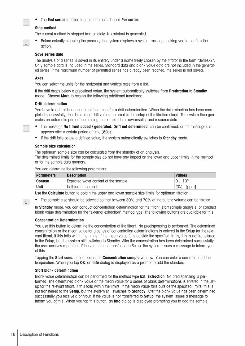
● The End series function triggers printouts defined Per series.
Stop methodThe current method is stopped immediately. No printout is generated.
● Before actually stopping the process, the system displays a system message asking you to confirm theaction.
Save series dataThe analysis of a series is saved in its entirety under a name freely chosen by the titrator in the form "SeriesXY".Only sample data is included in the series. Standard data and blank value data are not included in the generated series. If the maximum number of permitted series has already been reached, the series is not saved.
AxesYou can select the units for the horizontal and vertical axes from a list.
If the drift drops below a predefined value, the system automatically switches from Pretitration to Standbymode . Choose More to access the following additional functions:
Drift determinationYou have to add at least one titrant increment for a drift determination. When the determination has been completed successfully, the determined drift value is entered in the setup of the titration stand. The system then generates an automatic printout containing the sample data, raw results, and resource data.
● The message No titrant added / generated. Drift not determined. can be confirmed, or the message disappears after a certain period of time (60s).
● If the drift falls below a defined value, the system automatically switches to Standby mode.
Sample size calculationThe optimum sample size can be calculated from the standby of an analysis.The determined limits for the sample size do not have any impact on the lower and upper limits in the methodor for the sample data memory.
You can determine the following parameters:
Parameters Description ValuesContent Expected water content of the sample. 0 .. 106
Unit Unit for the content. [%] | [ppm]
Use the Calculate button to obtain the upper and lower sample size limits for optimum titration.
● The sample size should be selected so that between 30% and 70% of the burette volume can be titrated.
In Standby mode, you can conduct concentration determination for the titrant, start sample analysis, or conductblank value determination for the "external extraction" method type. The following buttons are available for this:
Concentration DeterminationYou use this button to determine the concentration of the titrant. No predispensing is performed. The determinedconcentration or the mean value for a series of concentration determinations is entered in the Setup for the relevant titrant, if this falls within the limits. If the mean value falls outside the specified limits, this is not transferredto the Setup, but the system still switches to Standby. After the concentration has been determined successfully,the user receives a printout. If the value is not transferred to Setup, the system issues a message to inform youof this.
Tapping the Start conc. button opens the Concentration sample window. You can enter a comment and thetemperature. When you tap OK, an Info dialog is displayed as a prompt to add the standard.
Start blank determinationBlank value determination can be performed for the method type Ext. Extraction. No predispensing is performed. The determined blank value or the mean value for a series of blank determinations is entered in the Setup for the relevant titrant, if this falls within the limits. If the mean value falls outside the specified limits, this isnot transferred to the Setup, but the system still switches to Standby. After the blank value has been determinedsuccessfully,you receive a printout. If the value is not transferred to Setup, the system issues a message toinform you of this. When you tap this button, an Info dialog is displayed prompting you to add the sample.
16 Description of Functions

Start sampleThis button is used to perform a sample analysis. When you press this button, an Info dialog is displayedprompting you to add the sample.
Once a sample has been added and the analysis started, you can use the Samples button to enter the samplesize (see Method Function: Sample (KF) > Sample.
SamplesYou can use this button to change the sample size of the sample currently being processed or to define thesample size for a new sample.
Stop analysisYou can use this button to cancel the measurement immediately during a sample, concentration, or blank valuedetermination.
● Before actually stopping the process, the system displays a message asking you to confirm the action.
Measured valuesYou can use the More and Measured values buttons to display a table of measured values during an analysisas an alternative to the online dialog.
See also
● Analysis Sequences (page 133)● Hidden method functions (page 126)● Starting an Analysis (page 133)● Sample (KF) (page 81)
17Description of Functions

4 SetupThis section tells you how to set up the titrator in accordance with your requirements so that you can carry outtitration.
TitrantsAuxiliary reagentsCalibration standardsConcentration and titer standards
Chemicals
SubstancesSensorsPumpsPeripheralsTitration StandsAuxiliary InstrumentsHomogenizer
Hardware
Liquid HandlerLanguageScreenBeepShortcuts
User settings
KeyboardSystemUser managementAnalysis and resources behavior
Global settings
Solvent ControlBlankValuesAuxiliary valuesMT-ServiceImport / ExportReset to factory settingsTitrator firmware historyBoard firmwareTerminalBoard dataDrivesBurettesUpdate
Mainten. & Service
Delete Mettler method template
Expired ResourcesNavigation: Home > Setup
Resources for which monitoring was selected in the settings can expire. Tap [Expired Resources] to open anoverview of all expired resources with the type, name and date of expiry of the respective resource.
See also
● Monitoring the life span of a resource (page 49)● Monitoring the usable life of a resource (page 48)
4.1 ChemicalsNavigation: Home > Setup > Chemicals
In Chemicals, configure and manage the titrant, auxiliary reagents, concentration/titer standard, and other substances. You can view and print out lists of chemicals that have already been defined. You can also specifynew chemicals or delete created chemicals.
18 Setup

Auxiliary reagents must be assigned to a pump with which they can be added. Titrants (independently of thetype) must each be assigned to a drive.
Settings ExplanationTitrants Titrants are managed together with burettes and burette drive.Auxiliary reagent Auxiliary reagents are liquid chemicals that can be used to aid the titration
process.Calibration standards Calibration standards are used for the calibration of sensors.Concentration and titerstandards
The titer standards required to determine the titer for the titrant used can be storedand managed.
Substances Any chemical substances that are required for performing your analyses can bemanaged using name, empirical formula, molecular weight, and equivalent number.
4.1.1 Titrants
Navigation: Home > Setup > Chemicals > Titrants
Titrants are managed together with burettes and burette drive (PnP with chip and traditional burettes withoutchips).For classical burettes, the relevant titrant data is entered manually. For PnP (Plug&Play) burettes, the data isautomatically read from the chip and automatically transferred to the instrument. If the chip is still blank, thedata must be entered in Setup or assigned to a titrant. The data is saved in both the titrator and in the chip.
Adding a titrant– In Titrants choose [New].
The windows to edit the parameters opens.
Define the following parameters for each titrant here:
Parameters Description ValuesType The type of titrant. You can select from the following three types
of titrant:
General titration: Classical titrants for general titration.Auxiliary reagent: If you are adding reagents manually using aburette.Karl Fischer titration: Karl Fischer titrant.
General titration | Auxiliary reagent | KarlFischer titration
Name Specify a descriptive name of your choice. ArbitraryConcentration The concentration of the titrant, in [mol/L].
For Type = General titration.
The non-dimensional concentration of an auxiliary reagent.For Type = Auxiliary reagent.
0.00001…100
0.00001…104
Titer The titer for the titrant.For Type = General titration.
0.00001…10
Reagent type The type of Karl Fischer titrant can be selected. This Influencesthe control behavior of a titration.
1-comp | 2-comp
Nominal conc. Specified concentration of the Karl Fischer titrant in [mg/mL]. 0.1…100Current conc. Actual concentration of the Karl Fischer titrant in [mg/mL]. 0.1…100Monitoringusable life
Specifies whether the usable life of a resource or a value is to bemonitored.
Yes | No
Monitoring lifespan
Specifies whether the life span of the resource is to be monitored. Yes | No
Lot/Batch The lot or batch of the reagent. Enter any designation. ArbitraryFill rate The filling rate of the burette in percent. 100% stands for maxi
mum filling rate.30…100
Burette volume Select the burette volume in [mL]. 1 | 5 | 10 | 20Drive Defines the drive on which you will use the burette containing the
titrant. Select the "PnP" entry for available but unused PnPburettes.
1…8 | PnP
19Setup

Serial number The serial number of the relevant device type. Arbitrary● Titrants (independently of the type) must each be assigned to a drive.● A maximum of 100 titrants can be defined in the instrument.● In PnP burettes, the serial number is entered automatically. This can, however, be changed.
See also
● Monitoring the usable life of a resource (page 48)● Titration (KF Vol) (page 108)● Monitoring the life span of a resource (page 49)
4.1.2 Auxiliary reagents
Navigation: Home > Setup > Chemicals > Auxiliary reagents
Auxiliary reagents are liquid chemicals that can be used to aid the titration process. Auxiliary reagents must beadded using a pump and can be used via the method functions Pumps and Rinse.
Adding an auxiliary reagent– In Auxiliary reagents choose [New].
The windows to edit the parameters opens.
Define the following parameters for each auxiliary reagent here:
Parameters Description ValuesName Specify a descriptive name of your choice. ArbitraryPump Use this setting to select a pump. List of available pumps● Auxiliary reagents must be assigned to a pump with which they can be added.● A maximum of 50 auxiliary reagents can be defined in the instrument.
4.1.3 Calibration standards
Navigation: Home > Setup > Chemicals > Calibration standards
Calibration standards are used for the calibration of sensors. The instrument contains various calibration standard lists for the calibration of pH sensors (pH buffer lists), ISE sensors (ISE standard lists) and conductivitysensors (conductivity standard lists) (see Appendix). In this dialog, you can view and print the predefined listsstored in the titrator, and create additional user-defined calibration standard lists for pH buffers and ISE andconductivity standards.
Adding a user-defined calibration standard lists1 In Calibration standards, choose [New].
The windows to edit the parameters opens.
2 Edit the parameters and save the settings.
After you have created a calibration standard list, you can add various buffers and standards to this list,depending on the type selected.
Parameters Description ValuesType Select the corresponding type for the new calibration standard
list.pH | pH | Auto pH |ISE | Conductivity
Name Specify a descriptive name of your choice. ArbitraryUnit The unit of measure to be used will depend on the type selected. pH | pM | pX | ppm |
mS/cm | µS/cmBase list Add the calibration standard lists of various pH buffers by select
ing them from the list.Only for Type = Auto pH.
List of available calibration standards
Ref. temperature Define the reference temperature of the buffer. -20…200
20 Setup
● To delete a self-defined calibration standard list from the titrator, you must first access the parameters in thelist via [Info]. From this dialog, you can delete the calibration standard list from the titrator memory byselecting [Delete].
● A maximum of 20 user-defined calibration standard lists and 10 auto pH buffer lists can be defined in thetitrator.
Adding a pH Calibration Standard (pH Buffer)After creating a calibration standard list of the type pH, add various pH buffers to it.
1 Add various pH buffers by choosing [New].
2 Enter the respective pH value of the buffer, based on the reference temperature from the calibration standardlist and tap [OK].
To reflect the temperature influence of a pH buffer, enter a maximum of 20 value pairs for each individual buffer composed of the temperature and corresponding pH value.
3 Choose a buffer and add various values by choosing [New].
4 Enter the respective pH value of the buffer, based on the reference temperature from the calibration standardlist.
5 Save the list by tapping [Save].
Adding a pH Calibration Standard (pH buffer) of type Auto pHFor a calibration standard list of the type Auto pH, the various pH buffers are detected by the titrator automatically. In order to ensure positive identification, the pH values of the individual solutions must differ fromeach other by at least two units.
1 Add various pH buffers to the calibration standard list by choosing [Add] and selecting them from the specified list.
2 Save the list by tapping [Save].
By doing so, the titrator offers only suitable pH buffers in order to ensure that the selected pH buffers alwaysdiffer from each other by at least two pH points.
Note● The temperature dependency of the individual pH buffers is also taken from the base list and cannot be edit
ed, only viewed.
Adding an ISE Calibration Standard (ISE Standard)After creating a calibration standard list of the type ISE, you can add various ISE standards to it.
1 Add various ISE standards to it by choosing [New].
2 Enter the corresponding value for the standard in the desired unit of measure, based on the reference temperature from the calibration standard list and tap [OK].
To reflect the temperature influence of an ISE standard, enter a maximum of 20 value pairs for eachindividual standard composed of the temperature and corresponding standard value.
3 Choose a buffer and add various values by choosing [New].
4 Save the list by tapping [Save].
Adding a Conductivity Calibration Standard (Conductivity Standard)After creating a calibration standard list of the type Conductivity, add various conductivity standards to it.
1 Add various conductivity standards to it by choosing [New].
2 Enter the conductivity for each standard based on the reference temperature from the calibration standardlist and tap [OK].
To reflect the temperature influence of a conductivity standard, enter a maximum of 20 value pairs foreach individual standard composed of the temperature and corresponding conductivity value.
3 Choose a buffer and add various values by choosing [New].
4 Save the list by tapping [Save].
21Setup

4.1.4 Concentration and titer standards
Navigation: Home > Setup > Chemicals > Concentration and titer standards
Enter and manage the and titer standards required for titer determinations and the Karl Fischer water standardsfor the concentration determination of KF titrants.
Adding a standard1 In Concentration and titer standards, choose [New].
The windows to edit the parameters opens.
2 Edit the parameters and save the settings.
Parameters Description ValuesType Defines the type of standard. solid | liquid | KFName Specify a descriptive name of your choice. ArbitraryPurity The purity of a solid standard, in percent.
Only for Type = solid.0.001…100.000
Concentration The concentration of a liquid standard, in [mol/L].Only for Type = liquid.
0.00001…100
Water content The water content of a Karl Fischer standard. 0.00001…106
Unit Unit for the water content of the Karl Fischer standard. mg/g | mg/mL | % |ppm | mg/piece
M The molar mass of a solid standard, in [g/mol]. 10-5…103
Density The density of a liquid standard, in [g/mL].Only for Type = liquid or KF.
0.0001…100
Equivalent number
The equivalent number "z" of the standard 1…9
Lot/Batch The lot or batch of the reagent. Enter any designation. ArbitraryMonitoringusable life
Specifies whether the usable life of a resource or a value is to bemonitored.
Yes | No
● All fields except for Lot/Batch must be filled before the standard can be saved.● A maximum of 50 titer standards can be defined.
See also
● Monitoring the usable life of a resource (page 48)
4.1.5 Substances
Navigation: Home > Setup > Chemicals > Substances
Any chemical substances that are required for performing your analyses can be managed using name, empirical formula, molecular weight, and equivalent number.
Adding a substance– In Substances choose [New].
The windows to edit the parameters opens.
Define the following parameters:
Parameters Description ValuesName Specify a descriptive name of your choice. ArbitraryEmpirical formula
Defines the empirical formula of the substance. Arbitrary
Molecularweight
Defines the molecular weight of the substance. 0.0001…104
Equivalent number
The equivalent number "z" of the standard 1…9
● A maximum of 100 substances can be defined.
22 Setup

4.2 HardwareIn Hardware, configure all the hardware components connected to the titrator.
Navigation: Home > Setup > HardwareSettings DescriptionSensors Configure and manage sensors to be used with the titrator. Pumps Configure a maximum of 20 pumps for use with the titrator.Peripherals Peripherals encompasses all input and output devices that belong to the titrator
environment.Titration Stands Configure the titration stands connected to the titrator. Auxiliary Instruments Auxiliary instruments can be any instruments that access a titrator's TTL or 24 V
output, stirrer or RS-232 connection and that are to be used in a method.Homogenizer Lists the available homogenizers according to their control type.Liquid Handlers Specify the setup parameters, for example to assign the ports to the related con
nections.
4.2.1 Sensors
Navigation: Home > Setup > Hardware > Sensors
You can configure and manage sensors to be used with the titrator as well as change settings already stored inthe titrator. The settings for an individual sensor can also be output to a printer. In addition, the correspondingmethod for sensor calibration can be accessed from here.
● A maximum of 50 sensors can be defined in the device.● Each sensor is associated with a specific type. Each sensor type can deliver measured values in one or
more units of measure. The following table provides information regarding which units of measure can beselected for a corresponding sensor type:
Sensor type Default unit of measure Eligible units of measuremV mV mVpH pH pH | mVISE pM pM / pX | ppm | mVPhototrode %T %T | A | mVPolarized mV mV | µATemperature °C °C | K | °FConductivity µS/cm µS/cm | mS/cm | µS | mS
1)Plug and Play sensors (PnP) are available for pH or mV measurements.
● Changing the unit of measurement for a sensor may render the calibration parameters and expiration dateparameters meaningless and result in their subsequent omission. This may also mean that the calibrationparameters are recalculated by the titrator (for temperature sensors), or that another set of calibration parameters is displayed (for ISE sensors).
Adding a sensor– In Sensors choose [New].
The windows to edit the parameters opens.
Plug and Play sensors (PnP)● If a PnP sensor is connected to the sensor input, this automatically generates an entry in the setup. All infor
mation (sensor name, type or inputs) is updated by the titrator (if a PnP sensor is not connected, the entry"PnP" appears for the sensor input ).
● The setup may contain several PnP sensors with identical sensor IDs but with different sensor input information. When the analysis starts, a validation is carried out during which the user is prompted to remove asensor. For several PnP sensors with the same ID, all entries apart from one are deleted when the sensorsare removed.
The following settings are available for configuring a sensor depending on the sensor type selected:
23Setup
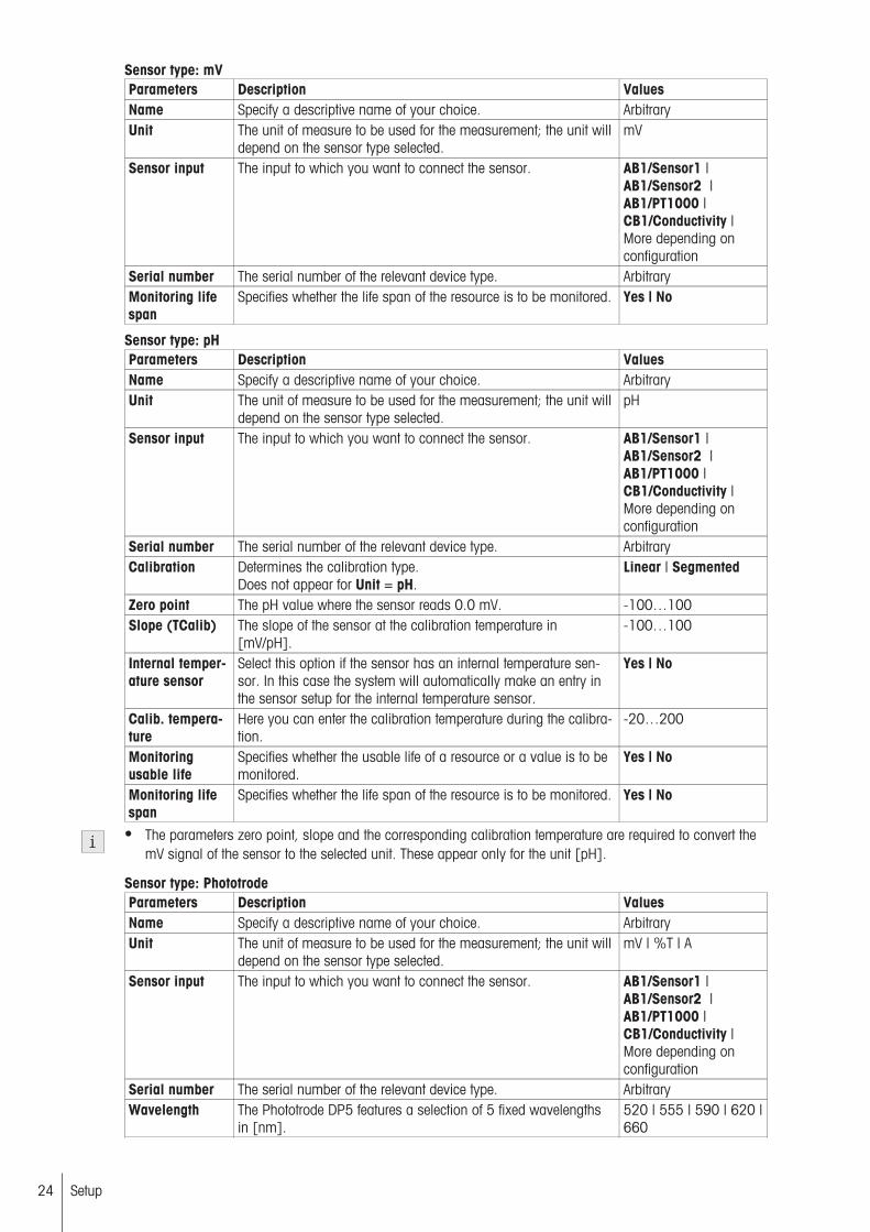
Sensor type: mVParameters Description ValuesName Specify a descriptive name of your choice. ArbitraryUnit The unit of measure to be used for the measurement; the unit will
depend on the sensor type selected.mV
Sensor input The input to which you want to connect the sensor. AB1/Sensor1 |AB1/Sensor2 |AB1/PT1000 |CB1/Conductivity |More depending onconfiguration
Serial number The serial number of the relevant device type. ArbitraryMonitoring lifespan
Specifies whether the life span of the resource is to be monitored. Yes | No
Sensor type: pHParameters Description ValuesName Specify a descriptive name of your choice. ArbitraryUnit The unit of measure to be used for the measurement; the unit will
depend on the sensor type selected.pH
Sensor input The input to which you want to connect the sensor. AB1/Sensor1 |AB1/Sensor2 |AB1/PT1000 |CB1/Conductivity |More depending onconfiguration
Serial number The serial number of the relevant device type. ArbitraryCalibration Determines the calibration type.
Does not appear for Unit = pH.Linear | Segmented
Zero point The pH value where the sensor reads 0.0 mV. -100…100Slope (TCalib) The slope of the sensor at the calibration temperature in
[mV/pH].-100…100
Internal temperature sensor
Select this option if the sensor has an internal temperature sensor. In this case the system will automatically make an entry inthe sensor setup for the internal temperature sensor.
Yes | No
Calib. temperature
Here you can enter the calibration temperature during the calibration.
-20…200
Monitoringusable life
Specifies whether the usable life of a resource or a value is to bemonitored.
Yes | No
Monitoring lifespan
Specifies whether the life span of the resource is to be monitored. Yes | No
● The parameters zero point, slope and the corresponding calibration temperature are required to convert themV signal of the sensor to the selected unit. These appear only for the unit [pH].
Sensor type: PhototrodeParameters Description ValuesName Specify a descriptive name of your choice. ArbitraryUnit The unit of measure to be used for the measurement; the unit will
depend on the sensor type selected.mV | %T | A
Sensor input The input to which you want to connect the sensor. AB1/Sensor1 |AB1/Sensor2 |AB1/PT1000 |CB1/Conductivity |More depending onconfiguration
Serial number The serial number of the relevant device type. ArbitraryWavelength The Phototrode DP5 features a selection of 5 fixed wavelengths
in [nm].520 | 555 | 590 | 620 |660
24 Setup
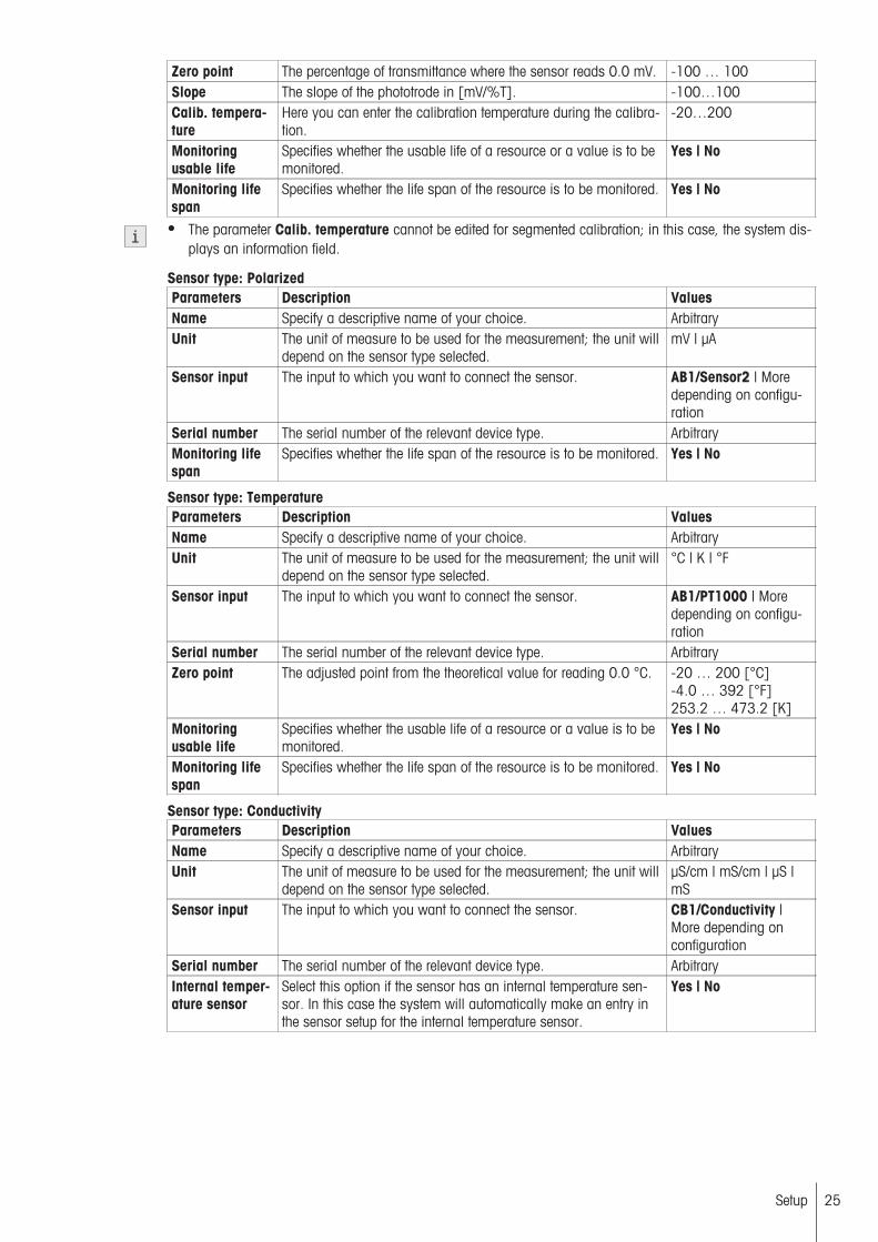
Zero point The percentage of transmittance where the sensor reads 0.0 mV. -100 … 100Slope The slope of the phototrode in [mV/%T]. -100…100Calib. temperature
Here you can enter the calibration temperature during the calibration.
-20…200
Monitoringusable life
Specifies whether the usable life of a resource or a value is to bemonitored.
Yes | No
Monitoring lifespan
Specifies whether the life span of the resource is to be monitored. Yes | No
● The parameter Calib. temperature cannot be edited for segmented calibration; in this case, the system displays an information field.
Sensor type: PolarizedParameters Description ValuesName Specify a descriptive name of your choice. ArbitraryUnit The unit of measure to be used for the measurement; the unit will
depend on the sensor type selected.mV | µA
Sensor input The input to which you want to connect the sensor. AB1/Sensor2 | Moredepending on configuration
Serial number The serial number of the relevant device type. ArbitraryMonitoring lifespan
Specifies whether the life span of the resource is to be monitored. Yes | No
Sensor type: TemperatureParameters Description ValuesName Specify a descriptive name of your choice. ArbitraryUnit The unit of measure to be used for the measurement; the unit will
depend on the sensor type selected.°C | K | °F
Sensor input The input to which you want to connect the sensor. AB1/PT1000 | Moredepending on configuration
Serial number The serial number of the relevant device type. ArbitraryZero point The adjusted point from the theoretical value for reading 0.0 °C. -20 … 200 [°C]
-4.0 … 392 [°F]253.2 … 473.2 [K]
Monitoringusable life
Specifies whether the usable life of a resource or a value is to bemonitored.
Yes | No
Monitoring lifespan
Specifies whether the life span of the resource is to be monitored. Yes | No
Sensor type: ConductivityParameters Description ValuesName Specify a descriptive name of your choice. ArbitraryUnit The unit of measure to be used for the measurement; the unit will
depend on the sensor type selected.µS/cm | mS/cm | µS |mS
Sensor input The input to which you want to connect the sensor. CB1/Conductivity |More depending onconfiguration
Serial number The serial number of the relevant device type. ArbitraryInternal temperature sensor
Select this option if the sensor has an internal temperature sensor. In this case the system will automatically make an entry inthe sensor setup for the internal temperature sensor.
Yes | No
25Setup
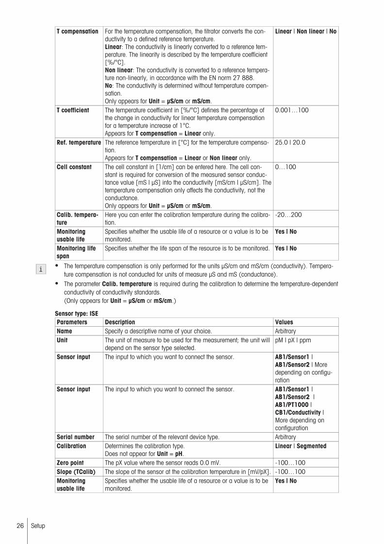
T compensation For the temperature compensation, the titrator converts the conductivity to a defined reference temperature.Linear: The conductivity is linearly converted to a reference temperature. The linearity is described by the temperature coefficient[%/°C].Non linear: The conductivity is converted to a reference temperature non-linearly, in accordance with the EN norm 27 888.No: The conductivity is determined without temperature compensation.Only appears for Unit = µS/cm or mS/cm.
Linear | Non linear | No
T coefficient The temperature coefficient in [%/°C] defines the percentage ofthe change in conductivity for linear temperature compensationfor a temperature increase of 1°C.Appears for T compensation = Linear only.
0.001…100
Ref. temperature The reference temperature in [°C] for the temperature compensation.Appears for T compensation = Linear or Non linear only.
25.0 | 20.0
Cell constant The cell constant in [1/cm] can be entered here. The cell constant is required for conversion of the measured sensor conductance value [mS | µS] into the conductivity [mS/cm | µS/cm]. Thetemperature compensation only affects the conductivity, not theconductance.Only appears for Unit = µS/cm or mS/cm.
0…100
Calib. temperature
Here you can enter the calibration temperature during the calibration.
-20…200
Monitoringusable life
Specifies whether the usable life of a resource or a value is to bemonitored.
Yes | No
Monitoring lifespan
Specifies whether the life span of the resource is to be monitored. Yes | No
● The temperature compensation is only performed for the units µS/cm and mS/cm (conductivity). Temperature compensation is not conducted for units of measure µS and mS (conductance).
● The parameter Calib. temperature is required during the calibration to determine the temperature-dependentconductivity of conductivity standards.(Only appears for Unit = µS/cm or mS/cm.)
Sensor type: ISEParameters Description ValuesName Specify a descriptive name of your choice. ArbitraryUnit The unit of measure to be used for the measurement; the unit will
depend on the sensor type selected.pM | pX | ppm
Sensor input The input to which you want to connect the sensor. AB1/Sensor1 |AB1/Sensor2 | Moredepending on configuration
Sensor input The input to which you want to connect the sensor. AB1/Sensor1 |AB1/Sensor2 |AB1/PT1000 |CB1/Conductivity |More depending onconfiguration
Serial number The serial number of the relevant device type. ArbitraryCalibration Determines the calibration type.
Does not appear for Unit = pH.Linear | Segmented
Zero point The pX value where the sensor reads 0.0 mV. -100…100Slope (TCalib) The slope of the sensor at the calibration temperature in [mV/pX]. -100…100Monitoringusable life
Specifies whether the usable life of a resource or a value is to bemonitored.
Yes | No
26 Setup

Monitoring lifespan
Specifies whether the life span of the resource is to be monitored. Yes | No
● For ISE sensors there are two independent calibration sets, one for the units "pM" or "pX" and one for theunit "ppm".
● When calibrating an ISE sensor in ppm units, the sensor's slope and zero point are specified in pX or pMunits.
See also
● Monitoring the life span of a resource (page 49)● Monitoring the usable life of a resource (page 48)
4.2.1.1 Sensor calibration and sensor test
Navigation: Home > Setup > Hardware > Sensors
pH, ISE, temperature and conductivity sensors can all be calibrated with the titrator. The phototrode can only bemanually calibrated. To do this the relationship between sensor signal and transmission capacity must bedetermined and the calibration parameter to be determined (normally only the gradient from a single point calibration) must be entered "manually" in the selected phototrode.
Temperature sensors are calibrated with the temperature standard "freezing water" (0°C). For conductivity sensors, you can choose the desired standard for the calibration from a standards list. Here a single point calibration is performed to determine the cell constant.
Two calibration modes are available for the calibrating pH and ISE sensors that can be selected. Linear calibration and segmented calibration.
If you want to calibrate a sensor with the titrator, you can either directly start an appropriate calibration methodor specifically for pH sensors use [Calibration/ Sensor test] in the sensor setup.
4.2.1.1.1 Linear calibration
Linear calibration is explained below taking the example of pH sensor.
In linear calibration the 1st step is the capture of measurement data and the interpolation of the pH values withthe buffer table to the effective values (the values used are only provided as an example):
Selected buffersolutions
During the calibration of the recordedtemperature
mV values measured during calibration
pH (effective) byinterpolationaccording to the pHbuffer table
1st Buffer 4.01 (at 25°C) 17 °C 172 mV 4.002nd Buffer 7.00 (at 25°C) 22 °C 0 mV 7.0123rd Buffer 9.21 (at 25°C) 27 °C -129 mV 9.19
In a second step, the mV measured values are converted to the averaged temperature "TAverage"(17°C+22°C+27°C) / 3 = 22°C):
27Setup
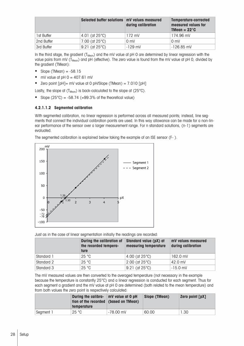
Selected buffer solutions mV values measuredduring calibration
Temperature-correctedmeasured values forTMean = 22°C
1st Buffer 4.01 (at 25°C) 172 mV 174.96 mV2nd Buffer 7.00 (at 25°C) 0 mV 0 mV3rd Buffer 9.21 (at 25°C) -129 mV -126.85 mV
In the third stage, the gradient (TMean) and the mV value at pH 0 are determined by linear regression with thevalue pairs from mV (TMean) and pH (effective). The zero value is found from the mV value at pH 0, divided bythe gradient (TMean):
● Slope (TMean) = -58.15● mV value at pH 0 = 407.61 mV● Zero point [pH]= mV value at 0 pH/Slope (TMean) = 7.010 [pH]
Lastly, the slope at (TMean) is back-calculated to the slope at (25°C).
● Slope (25°C) = -58.74 (=99.3% of the theoretical value)
4.2.1.1.2 Segmented calibration
With segmented calibration, no linear regression is performed across all measured points; instead, line segments that connect the individual calibration points are used. In this way allowance can be made for a non-linear performance of the sensor over a larger measurement range. For n standard solutions, (n-1) segments areevaluated.
The segmented calibration is explained below taking the example of an ISE sensor (F- ).
Just as in the case of linear segmentation initially the readings are recorded:
During the calibration ofthe recorded temperature
Standard value (pX) atmeasuring temperature
mV values measuredduring calibration
Standard 1 25 °C 4.00 (at 25°C) 162.0 mVStandard 2 25 °C 2.00 (at 25°C) 42.0 mVStandard 3 25 °C 9.21 (at 25°C) -15.0 mV
The mV measured values are then converted to the averaged temperature (not necessary in the examplebecause the temperature is constantly 25°C) and a linear regression is conducted for each segment. Thus foreach segment a gradient and the mV value at pH 0 are determined (both related to the mean temperature) andfrom both values the zero point is respectively calculated:
During the calibration of the recordedtemperature
mV value at 0 pH(based on TMean)
Slope (TMean) Zero point [pX]
Segment 1 25 °C -78.00 mV 60.00 1.30
28 Setup

During the calibration of the recordedtemperature
mV value at 0 pH(based on TMean)
Slope (TMean) Zero point [pX]
Segment 2 25 °C -72.00 mV 57.00 1.26
Afterward, the slope is converted to the reference temperature of 25°C (not necessary in this example, because(TMean) is already 25°C.
4.2.1.1.3 pH Sensor Test / Calibration
Navigation: Home > Setup > Hardware > Sensors
The pH sensor test is used to test the slope, zero point and drift of pH sensors. For the test, two buffers and thedrift of the pH sensor are measured. The measured values are transferred into the titrator settings.
1 In Sensors select the relevant pH sensor.
The windows to edit the parameters opens.
2 Tap [Calibration/ Sensor test].
The screen Start analysis opens.
3 In Action, select [Calibration] or [Sensor test].
4 In Method ID, select the relevant method.
5 Tap [Start] to perform the calibration or the sensor test.
● The button [Start] is only activated if a calibration method or a pH sensor test method is available.
See also
● Sample (calibration) (page 79)
4.2.1.2 Value ranges from sensor measuring units and control band
Sensor type Measuring unit
Value range Value range EP relative Value range Controlband
mV mV -2x10³…2x10³ -4x10³…4x10³ 0.1…4x10³
pH -100…100 -100.00…100.00 0.01…100pHmV -2x10³…2x10³ -4x10³…4x10³ 0.1…4x10³
pM | pX -100…100 -100.00…100.00 0.01…100ppm 0…106 -107…107 0.001…107
ISE
mV -2x10³…2x10³ -4x10³…4x10³ 0.1…4x10³
%T 0.001…100 -1x10³…1x10³ 0.1…1x10³
A 0…5 -106…106 0.01…106
Phototrode
mV -2x10³…2x10³ -4x10³…4x10³ 0.1…4x10³
mV 0…2x10³ -2x10³…2x10³ 0.1…2x10³PolarizedµA 0…220 -220.0…220.0 0.1…220°C -20…200 -220.0…220.0 0.1…220.0K 253.2…473.2 -220.0…220.0 0.1…220.0
Temperature
°F -4…392 -396.0…396.0 0.1…396.0µS/cm 0…106 -106…106 0.001…106
mS/cm 0…106 -106…106 0.001…106
µS 0…108 -106…106 0.001…106
Conductivity
mS 0…108 -108…108 0.001…106
4.2.2 Pumps
Navigation: Home > Setup > Hardware > Pumps
You can configure a maximum of 20 pumps for use with the titrator. Starting from the pump list, you can addnew pumps or select existing ones and change their settings. The list can also be printed and pumps can bedeleted.
29Setup

You can set up different pumps. For each pump, you need to specify an explicit, user-defined name, the pumping rate and the connection from which the pump should operate.
● The Karl Fischer Solvent Manager is predefined in Setup when connecting to the back of the instrument, andcannot be configured individually. All pump ports on the InMotion autosampler are available for connection.
● Only one Solvent Manager or Air pump can be defined per instrument.
Adding a diaphragm pump, peristaltic pump, or air pump– In Pumps choose [New].
The windows to edit the parameters opens.
Parameters Description ValuesType Defines the type of pump. Membrane |
Peristaltic | SolventManager | Reversible |Air pump
Name Specify a descriptive name of your choice. ArbitraryMax. pump rate Displays the pump rate in [mL/min] when the pump is operated
at 100%. This is stated by the manufacturer or determined experimentally.
0.1…1000
Pump output The output where you want to operate the pump. MB/PUMP1 |MB/PUMP2 |AB1/PUMP | Moredepending on configuration
4.2.3 Peripherals
Navigation: Home > Setup > Hardware > Peripherals
These settings encompass all input and output devices that belong to the titrator environment but that are notessential instruments for processing an analysis (peripherals cannot be accessed in methods). The computeralso counts as a peripheral device. The list of all peripheral instruments defined in the titrator, together with theparameters of each individual instrument can be printed out by a printer.
4.2.3.1 Balance
Navigation: Home > Setup > Hardware > Peripherals > Balance
Before defining a balance, you need to select the balance type. The titrator supports the following types of balance:
Balance type Supported balancesMettler AB | PB | PB-S | AB-S | PB-E | AB-E | College-S | SB | CB | GB | College-B |
HB | AG | PG | PG-S | SG | HG | XP | XS | XA | XPE | XSE | XVE | AX | MX |UMX | PR | SR | HR | AT | MT | UMT | PM | AM | SM | CM | MS | ML
Sartorius SartoriusMore --
METTLER TOLEDO BalancesThese balances support Plug'n'Play and are automatically recognized and configured by the titrator.
For automatic balance recognition, you need to ensure the following:
1. The balance has been started up and is connected to the titrator by a suitable cable,2. The balance has been set to "Bidirectional" (if necessary, set the "Host" parameter accordingly),3. The parameters for the RS-232 interface on the balance correspond with those on the titrator.
● As long as the balance is not connected to the titrator, the settings "Baud Rate", "Data Bit", "Stop Bit", "Parity" and "Handshake" can be entered manually. These are however automatically overwritten with the valuesidentified by the PnP as soon as the user sets the same transmission parameters at the balance and thetitrator.
30 Setup
Sartorius | OthersAfter you have selected this option and the system has recognized the balance, you can define the followingparameters:
Parameters Description ValuesName Specify a descriptive name of your choice. ArbitrarySerial number The serial number of the relevant device type. ArbitraryConnection The serial port to which the device is connected. Possible con
nections are located on the mainboard, the analog board and theconductivity board.
MB/COM1 |MB/COM2 | AB1/COM |More depending onconfiguration
Baud rate The baud rate for data transmission via the RS-232 interface. 1200 | 2400 | 4800 |9600 | 19200
Data bit Defines the number of data bits. 7 | 8Stop bit Defines the number of stop bits. (2 stop bits can only be selected
if 7 data bits are also selected at the same time.)1 | 2
Parity Defines the parity protocol. Even | Odd | NoneHandshake Data transmission via the RS-232 interface. (Only the handshake
option "Xon-Xoff" is available for serial connections on the analog and conductivity board in conjunction with a baud rate of9600.)
None | Xon-Xoff
● The settings for the baud rate, data bit, stop bit, parity, and handshake must agree for the balance and titrator!
● If None is selected as balance type that means that no balance is to be connected to the titrator.
4.2.3.2 Barcode reader
Navigation: Home > Setup > Hardware > Peripherals > Barcode reader
When a barcode is imported, the system checks whether the imported barcode is suitable for starting themethod. If so, the analysis start dialog is opened; all known data is entered there. If not, the barcode is ignored.If an analysis is already running with the same method ID, the sample is added to the end of the current analysis. An exception to this occurs if the End series barcode has previously been read. In this case, a new analysis is started (with the same method).
● Only one barcode reader can be defined.
Define the following parameters for a barcode reader:
Parameters Description ValuesName Specify a descriptive name of your choice. ArbitrarySerial number The serial number of the relevant device type. ArbitraryTransfer SmartCodes to LabX
Transfer barcode to LabX. Yes | No
4.2.3.3 USB-Stick
Navigation: Home > Setup > Hardware > Peripherals > USB-Stick
Commercially available USB sticks from USB Version 1.1 are supported.
You can assign a relevant name to the USB stick.
4.2.3.4 Printer
Navigation: Home > Setup > Hardware > Peripherals > Printer
Printer/RS-232 data exportThe printer types listed below as well as the RS232 interface for data export are supported by the titrator:
● USB printer with PCL protocol Version 4 and higher.Visit this site to find a list of compatible printers: http://www.mt.com/titration-printers
● RS232 data export for the output of data via the RS interface (not supported by LabX 2014 and later versions).
31Setup

Stripe printers● RS-232 (RS-P26)● USB compact printer
The following data is printed using the stripe printers:Results All except for curves and tables of measured valuesMethod function Record Overview
ResultsRaw resultsResource dataSample dataMethod data
Setup List printoutsParameter printoutsTotal printouts
Methods List printoutParameter printouts
Series List printoutParameter printouts
● The USB2 port on the mainboard is exclusively reserved for LabX.● If an RS printer or RS data export has been specified in the setup and the corresponding settings have been
saved, PnP recognition for the sample changer and balances is deactivated on this COM port.
● The compact printer does not allow the printing of manual operations. No automatically generated printoutsare produced either for: Calculations, instructions, referenced resources, equivalence point learn titration(LearnEQP) or changes to an analysis when in progress. The compact printer does not support all languages.For Karl Fischer determinations, manual concentration, drift and blank value analyses are printed out automatically.
Parameters Description ValuesPrinter type Selection of a printer.
USB compact printer, RS-232: These printers do not support alllanguages and can only print out a limited quantity of analysisdata and results.RS-232 data export: The data is transmitted regardless of theselected language. Only a limited quantity of data and results isexported.
USB printer | RS-232 |USB compact printer |RS-232 data export
Information on the RS-232 data export● In the method function Record, the parameter Summary must be activated (Record = outside loop) or Per
sample or Per series (Record = inside loop). The other settings in Record have no effect.• If the method function Record is inserted outside the loop, the data from the preceding loop and the data
between the End of sample and method functions Record are output.
● For the method type Titer, it is advisable for the method function Record to be inserted outside the loop,directly after the method function Titer. The parameter Summary should be activated.
● For the method type Calibration, it is advisable for the method function Record to be inserted outside theloop, directly after the method function Calibration. The parameter Summary should be activated.
● For the method type GT, the method function Record should be located inside the loop, directly in front ofEnd of sample. Either Per sample or Per series should be selected for the parameter Summary.
If data export is activated, the following data is transmitted:
● The most important sample data and results, either per sample or per series, according to the parametersetting in Summary of the method function Record.
● Automatic reports for drift, blank value and concentration determination in a Karl Fischer water contentdetermination if the global setting Print autom. KF protocols is also activatedNavigation: Home > Setup > Global settings > Analysis and resources behavior > Analysis sequencesettings
32 Setup

Depending on the selected printer type, the following parameters appear:● USB printer
Status Indicates whether the selected printer type is installed. InstalledName Specify a descriptive name of your choice. ArbitrarySerial number The serial number of the relevant device type. ArbitraryConnection Information on the USB port to which the printer is connected.
PnP is displayed if the printer is not connected to the titrator. MB1/USB1 | PnP
● RS-232
Status Indicates whether the selected printer type is installed. InstalledName Information on the name of the installed printer is displayed. RS-P26Serial number The serial number of the relevant device type. ArbitraryConnection The serial port to which the device is connected. Possible con
nections are located on the mainboard, the analog board and theconductivity board.
MB/COM1 |MB/COM2 | AB1/COM |More depending onconfiguration
Baud rate Information on the baud rate for data transmission via theRS-232 interface.
2400
Data bit Information on the number of data bits is displayed. 8Stop bit Information the number of stop bits is displayed. 1Parity Information on the parity defined for the report is displayed. NoHandshake Information on data transmission via the RS-232 interface. None● USB compact printer
Status Indicates whether the selected printer type is installed. InstalledName Specify a descriptive name of your choice. ArbitrarySerial number The serial number of the relevant device type. ArbitraryConnection Information on the USB port to which the printer is connected.
PnP is displayed if the printer is not connected to the titrator. MB1/USB1 | PnP
● RS-232 data export
Status Indicates whether the selected printer type is installed. InstalledConnection The serial interface for the RS-232 data export. MB/COM1 | MB/COM2Baud rate The baud rate for data transmission via the RS-232 interface. 1200 | 2400 | 4800 |
9600 | 19200Data bit Information on the number of data bits is displayed. 8Stop bit Information the number of stop bits is displayed. 1Parity Defines the parity protocol. Even | Odd | NoneHandshake Data transfer via the RS-232 interface. None | Xon-Xoff
The max. Xoff duration for transmitted data is around 30s.
See also
● Record (page 123)
4.2.3.5 PC settings
Navigation: Home > Setup > Hardware > Peripherals > PC settings
Configure these settings if you have your instrument connected to the PC software LabX.
● The PC with LabX installed must always be connected to the USB2 or Ethernet port on the mainboard.● After the settings have been modified, it may be necessary to restart the instrument.
Parameters Description ValuesConnect to LabXat start-up
If this parameter is activated, a connection to LabX will be established on startup.
Yes | No
Connection type Defines how the titrator is connected to the PC, either via the network connection or via the USB connection.
Network | USB
33Setup

Status Information on the connection status from the instrument to LabX. Connected | Disconnected
Port number Defines the port for a network connection of the titrator to LabX.Only appears for Connection type = Network.
1024…65535
4.2.3.6 Network settings
Navigation: Home > Setup > Hardware > Peripherals > Network settings
Configure these settings if you have your instrument connected to a network.
Parameters Description ValuesObtain IPaddress automatically
Indicates whether the IP address should be automaticallyobtained over the network.
Yes | No
IP address If the IP is not to be automatically obtained, you can enter it here. 000.000.000.000 …255.255.255.255
Subnet mask If you want to run the titrator on a local subnetwork, you candefine the subnet mask here that you want to use to link the subnet's IP address.
000.000.000.000 …255.255.255.255
Standard gateway
This is where you can enter the address of the standard gatewayfor communication between the various networks.
000.000.000.000 …255.255.255.255
4.2.3.7 Fingerprint reader
Navigation: Home > Setup > Hardware > Peripherals > Fingerprint reader
You can use a fingerprint reader to authenticate users on the titrator. In order to do this, the fingerprint readermust be activated on the titrator. The following parameters are available for this:
Parameters Description ValuesActivate fingerprint reader
Activates the fingerprint reader for authenticating users when logging onto the titrator.
Yes | No
Status Indicates whether the fingerprint reader is connected to the titrator.
Installed | Notinstalled
Name The designation of the fingerprint reader. ArbitraryConnection Information on the USB port to which the fingerprint reader is con
nected. PnP is displayed if the fingerprint reader is not connectedto the titrator.
PnP | USB 1
Register fingerprintNavigation: Home > User data
The following procedure must be performed in order to register each user:
1 Log on to the titrator with your user name (and possibly your password).
2 In Home, tap [User data] to open the corresponding window.
3 In User data, tap [Register fingerprint] to open the corresponding window.
4 Place the preferred finger on the fingerprint reader and repeat the step as prompted.
When completed, the message Registration successful. appears.
5 Confirm the message with the [OK] to return to the User data window.
6 Confirm with [OK] to return to the homescreen.
The next time you log on, the Fingerprint login window will appears. To log on, place the appropriate fingeron the fingerprint reader.
● You can only log on using the fingerprint reader if Activate fingerprint reader is selected.Navigation: Home > Setup > Hardware > Peripherals > Fingerprint reader
● You are still able to log on using a password. To do this, tap [Password login].
34 Setup

4.2.3.8 LevelSens
Navigation: Home > Setup > Hardware > Peripherals > LevelSens
The level sensor (LevelSens) can be used either to monitor the fill level of titration or solvent vessels or to prevent the overflow of waste vessels.
The level sensor is connected to the "LevelSens box", which is connected to the titrator via the CAN interface.The titrator automatically recognizes up to two of these boxes (PnP recognition). These appear in the settings.Navigation: Home > Setup > Hardware > Peripherals > LevelSens
1 In LevelSens, tap on a "LevelSens box".
The windows to edit the parameters opens.
2 The parameters Level, Waste or Inactive can be defined for the relevant sensor type
Activating level monitoring● At the start of a method or a manual operation.
The level is checked for all activated and connected sensors, regardless of whether they are used in themethod.
● At the start of each sample (GT).● After completion of a Karl Fischer analysis (KF).● Before the start of a KF Stromboli method.● Before replacing the solvent.● During the course of the following manual operations: Burette (Rinse, Rinse multiple burettes, Dispense,
Manual titration), Pump, Auxiliary instrument (output 24V), Sample changer (Pump, Rinse).
If the fill level is not reached or exceeded, a message appears with a prompt either to empty or fill the vessel(depending on the Setup setting: Waste or Level). The analysis is interrupted during this time. After the vesselhas been emptied or filled and the message has been confirmed, the analysis is resumed.
● Only two LevelSens boxes can be entered in the settings. Additional boxes do not generate an additionalentry.
● Entries in the settings can only be deleted if the corresponding LevelSens box is not installed.
● The sensor must be fitted in such a way that when the maximum fill level is reached, the analysis of a sample, the entire loop of a Stromboli method or a solvent replacement can be performed.
● The fill level is only checked before a sample analysis, at the start of a Stromboli method or before a solventreplacement.
Parameters Description ValuesName Information on the designation of the LevelSens box.
In the settings, the first detected box is entered as LevelSens Box1, the second as LevelSens Box 2.
-
Chip ID Information on the Chip-ID of the detected LevelSens box. -Position Information on the position of the LevelSens box connected to the
titrator.PnP | PnP1 | PnP2
Sensor 1type…Sensor 4type
Specifies the sensor type to be used. Level | Waste | Inactive
4.2.3.9 TBox
Navigation: Home > Setup > Hardware > Peripherals > TBox
The following parameters are available for the METTLER TOLEDO TBox: TBox connected. This parameter specifies whether or not the TBox is connected to the titrator.
If the TBox is installed on the titrator, then the TTL-outputs of the titrator are available in the pump setup.Navigation: Home > Setup > Hardware > Peripherals > TBox
4.2.4 Titration stands
Navigation: Home > Setup > Hardware > Titration Stands
35Setup

Starting from the titration stand list, you can add new titration stands or select existing ones and modify theirparameters. Furthermore the list can be printed out or individual titration stands can be deleted, whereby one ofeach type must be in the list.
Configure the following titration stands that can be connected to the titrator.
● Manual stand● Auto stand● External stand● Rondo/Tower A and Rondo/Tower B● InMotion T/Tower A and InMotion T/Tower B● Rondolino TTL● Stromboli TTL● KF stand
Adding a titration stand1 In Titration Stands tap [New].
The windows to edit the parameters opens.
2 In Type choose the type of titration stand to be added.
Edit the parameters according to the type of titration stand.
Parameters Description ValuesType Defines the type of the titration stand. Auto stand | External
stand | Manual stand |Rondo/Tower A |Rondo/Tower B |Rondolino TTL |Stromboli TTL | InMotion T/1A | InMotionT/1B | Rondo60/1A |Rondo60/1B | KF stand
4.2.4.1 Manual stand
The manual stand is typically used for the METTLER TOLEDO Manual Titration Stands. Before each sample inthe series is analyzed, a popup window requesting confirmation that the respective sample is in place willappear. The selected titration stand defines the stirrer output used in following method functions requiring afunction Stir.Parameters Description ValuesType Defines the type of the titration stand. -Name Defines the name of the titration stand. Additional titration stands
of a kind will have an index number assigned.List of available names
Stirrer output Defines the stirrer output. MB/Stirrer1 | MB/Stirrer2 | AB1/Stirrer |Internal stirrer | Moredepending on configuration
4.2.4.2 Auto stand
If you use an auto stand, the popup window that reminds you to add the respective sample does not appear.Thus an interruption-free analysis sequence can be guaranteed for multiple determinations with an automationunit. The selected titration stand defines the stirrer output used in following method functions requiring a function Stir.Parameters Description ValuesType Defines the type of the titration stand. -Name Defines the name of the titration stand. Additional titration stands
of a kind will have an index number assigned.List of available names
36 Setup

Stirrer output Defines the stirrer output. MB/Stirrer1 | MB/Stirrer2 | AB1/Stirrer |Internal stirrer | Moredepending on configuration
4.2.4.3 External stand
The external stand is typically used for stands not directly attached to the titrator. Before each sample in theseries is analyzed, a popup window requesting confirmation that the resepective sample in place will appear.The selected titration stand defines the stirrer output used in following method functions requiring a functionStir.Parameters Description ValuesType Defines the type of the titration stand. -Name Defines the name of the titration stand. Additional titration stands
of a kind will have an index number assigned.List of available names
Stirrer output Defines the stirrer output. MB/Stirrer1 | MB/Stirrer2 | AB1/Stirrer |Internal stirrer | Moredepending on configuration
4.2.4.4 Rondolino TTL
The Rondolino sample changer can hold 9 samples to be tested in sequence. The Rondolino connects to theTTL port on the titrator. The selected titration stand defines the stirrer output used in following method functionsrequiring a function Stir.Parameters Description ValuesType Defines the type of the titration stand. -Name Defines the name of the titration stand. Additional titration stands
of a kind will have an index number assigned.List of available names
Stirrer output Defines the stirrer output. MB/Stirrer1 | MB/Stirrer2 | AB1/Stirrer |More depending onconfiguration
Connection Information on the connection type. MB/TTL
4.2.4.5 Stromboli TTL
The Stromboli Karl Fischer Drying Oven sample changer can hold 14 vialed oven samples and one blank vial.The Stromboli connects to the TTL port on the titrator.
Parameters Description ValuesType Defines the type of the titration stand. -Name Defines the name of the titration stand. Additional titration stands
of a kind will have an index number assigned.List of available names
Stirrer output Defines the stirrer output. MB/Stirrer1 | MB/Stirrer2 | AB1/Stirrer |Internal stirrer | Moredepending on configuration
Connection Information on the connection type. MB/TTLDrift Value of the last drift determination [µg/min]. 0.0…106
Determinationmethod
Method name of the method used for the determination. Method name
Date / Time Date and time of the determination. Date and timePerformed by Name of the user performing the determination. User name
37Setup

4.2.4.6 InMotion
The InMotion Autosamplers can hold multiple samples depending on the base unit (Flex, Pro or Max) and theaccompanying sample rack. The InMotion Autosampler connects to USB1 on the titrator. InMotion Autosamplers and attached towers are PnP devices that are automatically recognized and installed upon connection tothe titrator. If a second InMotion Autosampler is to be attached, a USB expander must be used at the titrator forthe second USB connection. The USB expander ports on the back of the first InMotion Autosampler attached canalso be used for the connection. The first InMotion device attached is labelled InMotion T/1A and the secondattached to the system will be labeled InMotion T/2A in the list. If unattached and reattached after the initialinstallation, the titrator will know which InMotion Autosampler is /1 and /2 according their Chip ID. An InMotionAutosampler can also manually be added to the Titration Stand list with default parameters if needed for methodprogramming.
Parameters Description ValuesType Defines the type of the titration stand. -Name Defines the name of the titration stand. Additional titration stands
of a kind will have an index number assigned.List of available names
Base type Indicates the sample changer type. Flex | Pro | MaxStirrer output Defines the stirrer output. MB/Stirrer1 | MB/Stir
rer2 | AB1/Stirrer |InMotion1/Stirrer1…InMotion1/Stirrer6 | InMotion2/Stirrer1…InMotion2/Stirrer6 | More dependingon configuration
Connection Indicates the connection type. PnP | MB/USB 1Chip ID Shows the ID of the identification chip of the sample changer. Unique numberCoverUp Indicates whether this option is installed. Installed | Not
installedRFID inner Indicates whether the RFID option is installed for the second row
of the rack.Installed | Notinstalled
RFID outer Indicates whether this option is installed. Installed | Notinstalled
Barcode reader Indicates whether this option is installed.Only the outer rack row can be used with the barcode option.
Installed | Notinstalled
Rack Indicates the type of the installed rack.Standard: Standard rack.Waterbath: Rack including a wather bath.Dual: Rack type with two types of beaker sizes.PnP: No rack is detected.
Standard | Waterbath /Dual / PnP
Rack size Indicates the size of the installed rack. Number of positions onthe rack
Beaker height Defines the beaker height [mm].For COD kit = Yes the value range is different.
65…215
Conditioningbeaker
Defines if a specific condition beaker is used. The last beakerposition of the rack is the specific conditioning beaker position.This parameter is stored in the rack.
Yes | No
Rinse beaker Defines if a specific rinse beaker is used. Yes | NoSpecial beaker1…Specialbeaker 4
Defines if specific special beaker are used. Rinse beaker positions are next to the conditioning beaker.These parameters are stored in the rack.
Yes | No
NoteWhen fixed beakers are defined, they cannot be used for samples and are reserved for Conditioning, Rinseand Line rinse method functions only. The fixed beakers reserve the last available positions on the rack, in theorder stated above, with conditioning beaker being last.
38 Setup

COD kit Defines if the system is used with the Aliquot Kit.For InMotion Pro with 25 mL rack only.This parameter is stored on the InMotion.
Yes | No
Aliquot beaker Defines whether the extension on InMotion is installed for analiquot beaker. Aliquoting is not possible with all rack types. ForInMotion Pro only.This parameter is stored on the InMotion.
Yes | No
4.2.4.7 Rondo60
The Rondo autosampler can hold 12-60 samples depending on the accompanying sample rack. The Rondo isconnected to either MB1/COM or MB2/COM ports on the titrator. The Rondo60 is automatically named /1 or /2according to the COM port is attached. The Rondo and attached Towers are PnP devices that are automaticallyrecognized and installed upon connection to the titrator. A Rondo can also manually be added to the TitrationStand list with default parameters if needed for method programming.
Parameters Description ValuesType Defines the type of the titration stand. -Name Defines the name of the titration stand. Additional titration stands
of a kind will have an index number assigned.List of available names
Stirrer output Defines the stirrer output. MB/Stirrer1 | MB/Stirrer2 | AB1/Stirrer |Rondo/1A Stirrer |Rondo/2A Stirrer |More depending onconfiguration
Connection Indicates the connection type. PnP | MB1/COM |MB2/COM
Rack Indicates the size off the installed rack. 20 | 12 | 15 | 30 | 60Beaker height Beaker configuration of the installed rack. 90 | 110 | 150 | 210Tower position Indicates the tower position configuration off Rondo. Left | RightConditioningbeaker
Conditioning beaker setting of the installed rack. Installed | Notinstalled
Rinse beaker Indicates the beaker setting of the installed rack. Installed | Notinstalled
Special beaker1
Indicates the special beaker setting of the installed rack. Installed | Notinstalled
Special beaker2
Indicates the special beaker setting of the installed rack. Installed | Notinstalled
CoverUp Defines whether a CoverUp unit is connected to the Rondo and, ifso, to which port. Select None if there is no CoverUp unit on yourRondo.Only appears when Rack = 20 has been selected.
Rondo/1 TTL-Out 1 |Rondo/1 TTL-Out 2 |Rondo/2 TTL-Out 1 |Rondo/2 TTL-Out 2 |MB/TTL-Out 1 |MB/TTL-Out 2 | None
4.2.4.8 KF stand
The selected titration stand defines the stirrer output used in following method functions requiring a functionStir.Parameters Description ValuesType Defines the type of the titration stand. -Name Defines the name of the titration stand. Additional titration stands
of a kind will have an index number assigned.List of available names
Stirrer output Defines the stirrer output. MB/Stirrer1 | MB/Stirrer2 | AB1/Stirrer |Internal stirrer | Moredepending on configuration
39Setup
4.2.5 Auxiliary instruments
Navigation: Home > Setup > Hardware > Auxiliary instrument
Auxiliary instruments can be any instruments that access a titrator's TTL or 24 V output, stirrer or RS-232 connection and that are to be used in a method (e.g. valves, dispensers).An auxiliary instrument is switched on for a predefined period or switched on and then switched off again viathe corresponding command. The instruments are controlled via the method function Auxiliary instrument.Auxiliary instruments form part of a method, while peripherals are classified as input/output devices (printers,balances, barcode readers etc.), which do not have direct access to methods.
Starting from the auxiliary instrument list, you can add new auxiliary instruments or select existing ones ormodify their parameters. Furthermore the list can be printed out at a printer or selected auxiliary instruments canbe deleted.
● A maximum of 50 auxiliary instruments can be saved in the titrator.
Adding an auxiliary instrument1 In Auxiliary instrument choose [New].
The windows to edit the parameters opens.
2 In Control type you must first select the manner in which the auxiliary instrument is to be controlled.
After you have selected the relevant type, you can determine the parameters.
Parameters Description ValuesName Specify a descriptive name of your choice. ArbitraryControl type Select the manner in which the auxiliary instrument is to be con
trolled.Output 24 V | Out TTL(Single pin) | Input TTL(Single pin) | TTL(Multipin) | Stirrer |RS-232
Output 24 V/Stirrer (0-18V output)Parameters Description ValuesOutput Indicates which port on the titrator you want to use for the auxil
iary instrument.MB/PUMP1 |MB/PUMP2 |AB1/PUMP | Moredepending on configuration
TTLParameters Description ValuesOutput Indicates which port and which pin on the titrator you want to use
for the auxiliary instrument.Does not appears for Control type = Input TTL (Single pin).
MB/TTL-Out 1 |MB/TTL-Out 2 |MB/TTL-Out 3 |MB/TTL-Out 4 | Moredepending on configuration
Input The input where the auxiliary instrument should be queried.Only appears for Control type = Input TTL (Single pin).
MB/TTL-In 1 | MB/TTL-In 2
RS-232Parameters Description ValuesConnection The serial port to which the device is connected. Possible con
nections are located on the mainboard, the analog board and theconductivity board.
MB/COM1 |MB/COM2 | AB1/COM |More depending onconfiguration
Baud rate The baud rate for data transmission via the RS-232 interface. 1200 | 2400 | 4800 |9600 | 19200
Data bit Defines the number of data bits. 7 | 8Stop bit Defines the number of stop bits. (2 stop bits can only be selected
if 7 data bits are also selected at the same time.)1 | 2
Parity Defines the parity protocol. Even | Odd | None
40 Setup
Handshake Data transmission via the RS-232 interface. (Only the handshakeoption "Xon-Xoff" is available for serial connections on the analog and conductivity board in conjunction with a baud rate of9600.)
None | Xon-Xoff
4.2.6 Homogenizer
Navigation: Home > Setup > Hardware > Homogenizer
This window lists the available homogenizers according to their control type. The list can be sorted and printedout.Depending on the control type, there are two different types of homogenizer.
– In Homogenizer choose the required entry.
The window to edit the parameters opens.
Homogenizer TTLParameters Description ValuesOutput Defines the output to which the device is connected. MB/TTL-Out
1…MB/TTL-Out 4 |Rondo/1 TTL-Out1…Rondo/2 TTL-Out4 | (More depending onconfiguration)
Homogenizer RSParameters Description ValuesStatus Determines whether or not the titrator is connected to the homog
enizer.Installed | Notinstalled
Output Indicates which port on the titrator you want to use. MB/COM1 |MB/COM2 | AB1/COM |(More depending onconfiguration)
● For the homogenizer of type PT 1300D (RS interface), the panel for changing or saving the speed duringoperation is blocked via the titrator (GLP conformity).
● It is not possible to change an entry while a method that uses a homogenizer is running.● For the status Installed, balance and sample changer polling is deactivated.● The parameters for serial connection are for information only and cannot be changed.
4.2.7 Liquid Handler
Navigation: Home > Setup > Hardware > Liquid Handler
If a Liquid Handler is connected, the titrator detects the Liquid Handler automatically (PnP) and the identification parameters are transferred to the titrator's setup. Specify the setup parameters, for example to assign theports to the related connections. Port 6 is fixed assigned to the waste port. The waste port is required to discharge residual solutions upon liquid exchange or to remove excessive liquid volumes from the burette.
– In Liquid Handler choose the detected Liquid Handler.
The window to edit the parameters opens.
In this dialog you obtain the following parameters:
Parameters Description ValuesName The first connected Liquid Handler is displayed as Liquid Handler
1 and the second one as Liquid Handler 2.
For T90 you can change the name only if one Liquid Handler isavailable and is not connected.
Liquid Handler 1 | Liquid Handler 2
Chip ID Information on the ID of the Liquid Handler's PnP chip. ArbitraryPosition Information on the position of the Liquid Handler. 1 | 2 | PnP (default val
ue)
41Setup
Burette volume Information on the volume [mL] of the Liquid Handler's burette. 50 mL (default)SNR Buretteglass
The serial number of the burette glass can be entered. Arbitrary
Port 1…6 Indicates the position of the multiport valve. Yes | NoConnection The corresponding ports and the connected components can be
designated. The names can then be selected within the methodfunction Liquid Handling.
Arbitrary
● After the removing of the Liquid Handler, the data (name, chip-ID, burette volume, SNR burette glass, connections and port assignments) remain at the titrator's setup.
● When a Liquid Handler is connected, the chip-ID will be overwritten.● When more than one Liquid Handler are connected, the existing Setup entries will be assigned to the relat
ed.Liquid Handler, according to the connection order.
● The last Liquid Handler in the list cannot be deleted.
4.3 User settingsNavigation: Home > Setup > User settings
These settings contains the options that can be made specifically for each currently logged in user.
You can configure the language, the screen settings (for the touchscreen), the layout of the alphanumeric andnumeric keyboard, the use of beeps, and shortcuts for each user.
4.3.1 Language
Navigation: Home > Setup > User settings > Language
Define the following parameters:
Parameters Description ValuesTouchscreen Defines the language for operation of the terminal. German | English |
French | Italian | Spanish | Chinese | Russian |Polish | Korean
Record Defines the language in which the protocols are to be printed out. German | English |French | Italian | Spanish | Chinese | Russian |Polish | Korean
● For the Chinese and Korean language settings, it is not possible to print using the USB-P25 tape printer.● For Polish, records can be printed on the USB-P25 tape printer without special characters.
4.3.2 Screen
Navigation: Home > Setup > User settings > Screen
Define the following parameters:
Parameters Description ValuesPrimary color Here various color schemes for the user interface can be select
ed.Gray | Blue | Green |Red
Brightness Specifies the display brightness in [%]. 50 | 60 | 70 | 80 | 90 |100 [%]
Button shape Defines whether to display the buttons in the menus with squareor rounded corners.
Rounded | Square
Screen saver Here you can define whether the screen saver should be used. Yes | NoWait time Defines how long in [min] the system should wait after the user's
last action on the terminal before activating the screen saver.1…1000
4.3.3 Beep
Navigation: Home > Setup > User settings > Beep
42 Setup

Define the following parameter:
Parameters Description ValuesAt push of a button
Enables a beep when tapping on the touch screen. Yes | No
4.3.4 Shortcuts
Navigation: Home > Setup > User settings > Shortcuts
Each user can manage the shortcuts that they have created. Individual shortcuts can be selected and deletedand the following parameters of a shortcut can be changed:
Parameters Description ValuesDescription Any name for the shortcut. ArbitraryImmediate start The method, series, or manual operation can be started immedi
ately. This enables you to start the analysis without any interfering dialog.
Yes | No
Homescreenposition
You can select the free position for the shortcut on the Homescreen.
1…12
4.3.5 Keyboards
Navigation: Home > Setup > User settings > Keyboards
In this dialog, you can define the layout for the alphanumeric and the numeric input fields. The following settings are available:
Parameters Description ValuesABC keyboard Determines the layout of the alphanumeric input field. English | French | Ger
man123 keyboard Defines the organization of the keys for the numeric input field. Calculator | Phone
4.4 Global settingsIn Global settings, you can make general settings on the titrator that apply for all users. The settings in thisdialog can only be changed by users with the appropriate authorizations.
Navigation: Home > Setup > Global settingsSettings ExplanationSystem settings General settings that apply to all users (time, date.).User management Managing user accounts and assigning rights.Analysis and resourcesbehavior
Settings for monitoring the expiration dates and life span of resources (determining the actions of the titrator before, during and after the performance of an analysis). Settings for the response of the titrator when resources are deleted or whenPnP resources are identified.
Solvent Control Prompts the user to replace the solvent. For information on the process for replacing the solvent (Manual operation).
4.4.1 System
Navigation: Home > Global settings > System
Titrator identificationYou can enter and assign any ID consisting of at least four characters to the titrator.
Parameters Description ValuesTitrator ID Define the instrument identification. -Titrator Indicates the titrator type. T50 | T70 | T90Serial number Information on the serial number of the instrument. -Titrator FW version
Information on the firmware version of the instrument. -
43Setup

Date / TimeYou can define the format used to display the date and time and set the titrator date and time.
Parameters Description ValuesDate format Defines the format for displaying the date. mm/dd/yyyy |
dd/mm/yyyyTime format Defines the format for displaying the time. 24h | a.m./p.m.Date Enter the current date. -Time Enter the current time. -
Header and footerDefine whether all printouts generated by the titrator should have a header or footer. The content of these headers and footers can be entered directly into the respective setting.
As part of the end of record, signature fields are appended to the respective printout consisting of a declaration(e.g. Approved by) followed by an empty line. A personal signature can be then be entered on this line.
Parameters Description ValuesHeader Activates the header on print outs. Yes | NoText Defines the text for the header.
Only for Header = Yes.Arbitrary
Footer Activates the footer on print outs. Yes | NoText Defines the text for the footer.
Only for Footer = Yes.Arbitrary
End of report Select the information to be printed at the end of a report. Created by | Modifiedby | Checked by |Approved by
Data storageIn the T50 and T70, the system only saves the results from the last analysis (series or individual sample). Inthe T90 select [Select Series] to select the results from the last two analyses.
Parameters Description ValuesDelete data onshut down
Define if analysis data is to be deleted from the titrator memorywhen the titrator is shut down.
Yes | No
4.4.2 User Management
Navigation: Home > Setup > Global settings > User management
Here you manage users, user groups, and account policies for the titrator.A maximum of 30 different users can be defined for the titrator, but only one user at a time can be logged ontothe instrument (single user operation). One user with administrative rights is already saved on the instrument.
User accounts can be deleted, printed out and edited.
Users1 In User management tap [Users] to open the list of users.
2 To add a new user, tap [New].- or -Edit an existing user.
You can define the following parameters for each user account:
Parameters Description ValuesUser Name The user's login ID. ArbitraryFull Name The user's full name. ArbitraryUser group 1 The first user group to which the user is assigned. List of user groupsMember of usergroup 2…Member of usergroup 10
Specifies whether the user is assigned to other user groups (2 toa maximum of 10). Always appears in a pair with the parameter.
Yes | No
44 Setup
User group2…User group10
Always appears paired with the parameters Member of usergroup 2…Member of user group 10.
List of user groups
Description Any description for the user account or for the user. ArbitraryReset password If activated, the user's password is reset to "123456" and the
user is prompted to change their password the next time they login.Only appears if Enforce password/fingerprint = Yes is selectedin Account Policies.
Yes | No
Lock user If activated, the user account is locked.Only appears if Enforce password/fingerprint = Yes is selectedin Account Policies.
Yes | No
Enforce password change
If activated, the user is forced to change their password the nexttime they log on to the titrator.Only appears if Enforce password/fingerprint = Yes is selectedin Account Policies.
Yes | No
● If the parameter Reset password is activated, the parameter Enforce password change will be automatically activated.
● The default password for this user (User ID: "Administrator") is "123456" (do not enter inverted commas).
GroupsHere you define and manage up to 10 different user groups. Different rights can be assigned to each usergroup. A user is always assigned to at least one user group. All user groups, up to the administrators' usergroup that possesses full authority, can be deleted.
1 In User management tap [Groups] to open the list of groups.
2 To add a new group, tap [New].- or -Edit an existing group.
You can define the following parameters for each group:
Parameters Description ValuesGroup name A freely definable name for the user group. ArbitraryDescription Any description for the user account or for the user. ArbitraryEditing methods If a user group enjoys this right then the members of this group
can create methods in the method editor and may freely editthem.
Yes | No
Editing seriesand samples
If a user group has this authorization, a member of this groupwill be able to create serial templates and samples and have fullediting privileges for them.
Yes | No
Editingresources andperipherals
If a user group enjoys this right then the members of this groupcan create resources and peripheral devices and may freely editthem.
Yes | No
Global andanalysissequence settings
If a user group enjoys this right then the members of this groupcan edit global settings in the setup.
Yes | No
Editing userspecific settings
If a user group enjoys this right then the members of this groupcan edit user-specific settings in the setup.
Yes | No
Editing results If a user group enjoys this right then the members of this groupcan edit the saved results in the setup.
Yes | No
Starting methods and series
If a user group has this right, then a group member may startmethods from the method list or from the analysis start screen.
Yes | No
Executing manual operations
If a user group enjoys this right then the members of this groupcan perform manual operations.
Yes | No
45Setup

Account PoliciesIn account policies define the actions of the titrator when it is started up.
Parameters Description ValuesEnforce password/fingerprint
If this parameter is activated, the titrator always starts with thelogin screen (even if only one user is defined for the instrument).The user name must always be entered in the login screen manually (the corresponding input box is always initially empty).
Yes | No
● If this option is selected for an instrument with factory settings, the titrator will demand the password for thepredefined user (User ID: "Administrator") the next time it is booted up. This password is "123456" (do notenter inverted commas).
Min. no. of characters
Specifies the minimum number of characters required for userpasswords. If this parameter is changed, then users whose password does not meet this requirement will be requested to changetheir password accordingly the next time that they log in.
Yes | No
4.4.3 Analysis and resources behavior
The settings that you make here relate to the sequence of the analysis of samples or series with the aid of methods.
● You can define the actions of the titrator when started, during an analysis and afterward.● You can also program the response of the titrator to the deletion of resources or when it identifies PnP
resources.
Navigation: Home > Setup > Global settings > Analysis and resources behavior
Analysis sequence settingsThe analysis sequence settings can only be modified if no tasks are currently being performed by the titrator.
You can make the following settings that influence the sequence of an analysis.
Parameters Description ValuesShow requiredresources atstart
When an analysis is started a screen appears displaying allresources required for the analysis and their status (available,not-available, locked or in use). If an individual entry is selectedfrom this screen then the user receives additional informationabout the respective resource.However, if "no" is selected, then the required resources are stillchecked when the analysis is started and if necessary, an appropriate error message is issued.
Yes | No
Show SOP If an SOP (standard operating procedure) has been defined in theTitle method function then this will be displayed before themethod is started provided that "yes" has been selected.
Yes | No
● If Show required resources at start and Show SOP parameters were set to "Yes" at the start of a job series,all SOPs and subsequently all resources for the individual sample series must be confirmed before the jobseries is started. In this way a job series can be performed after it has been started without any further interruption.
Confirm after acompleted rackrotation
This setting affects analyses that are to be performed on the sample changer and require more beakers than can be accommodated on the rack of the sample changer.If Yes has been selected for this parameter, a warning messageis issued after a complete revolution of the sample changer andbefore a position is approached on the tray that has already beentitrated. This warning must be acknowledged by the user.
Yes | No
InMotion beakerdetection auto-skip
If the beaker is not detected or the sample data is not readable(e.g. RFID or barcode) the system automatically skips sampleafter 10 min without requiring confirmation.
Yes | No
46 Setup

Show resultsafter analysis
If a manual or external titration stand is being used, then theresults for a sample are automatically displayed after they havebeen analyzed and must be acknowledged by the user before theanalysis can be continued. With Auto stand the results are displayed for a certain period and are not to be confirmed.
The activated parameter is valid for the following functions:Analysis: the results for a sample are shownCalibration/Loop: The results of the calibration are shown(slope, zero point)Sensor test: The results of the test are shown (slope, zero point,drift and sensor test OK / not OK)
Yes | No
Check localprinter connection and wait
When selected, the availability of a printer is checked at thebeginning of the method.If not selected and no printer is connected, the method functionRecord is skipped. If a printer is connected, the method functionRecord is executed even if this parameter is not selected.
Yes | No
Print autom. KFprotocols
Controls printouts for manual drift, concentration, and blank value determinations.
Yes | No
Save results Defines if date, time, user, Methods ID, sample ID, results, resultunit per sample is saved in a file. If this parameter is activatedand the stick is not detected during the data writing process, youcan stop the process or you can plug in another USB-stick for thedata writing and to continue the method run.Only for Check USB-Stick connection and wait = Yes.
To USB-Stick | No
Check USB-Stickconnection andwait
If this parameter is activated, the presence of a USB - Stick is validated at the start of the analysis.
Yes | No
Resources behaviorUse the following parameters to configure how the titrator responds to the deletion of resources and its responseto the automatic identification of PnP resources.
Parameters Description ValuesInformationwhen deletingresources
Defines if a confirmation will be requested before a resource isdeleted.
Yes | No
Informationwhen recognizing PnPresources
Defines if a confirmation will be requested every time a PnPresource is identified.
Yes | No
Action when exceeding usable lifeIf it is determined by the titrator that the expiration dates of a resource have been exceeded, then the titrator mayperform various actions.
Warning The user is warned that the resource's usable life has been exceeded and the raw results andresults determined with the respective resource will be labeled accordingly.
Block The user is notified that the usable life of the resource has been exceeded and it is no longerpossible to start the analysis with the affected resource. (Methods that result in renewal ofthis resource can however still be started.)
None If you select "none" then the analysis is started without message in spite of the exceededusable life. The expiry of the expiration date will, however, be logged.
Parameters Description ValuesSensors The action is executed if the system determines at the start of an
analysis that the usable life of a sensor has been exceeded.None | Warning | Block
Titrants The action is executed if the system determines at the start of ananalysis that the expiration date of a titrant has been exceeded.
None | Warning | Block
Titer/conc. stds The action is executed if the system determines at the start of ananalysis that the expiration date of a titrant or a concentrationstandard has been exceeded.
None | Warning | Block
47Setup

Auxiliary values This action is performed if the system determines at the start ofan analysis that the usable life of an auxiliary value that is to beused in the analysis has been exceeded.
None | Warning | Block
Blank values This action is performed if the system determines at the start ofan analysis that the usable life of a blank value that is to be usedin the analysis has been exceeded.
None | Warning | Block
Action when exceeding life spanIf, at the start of an analysis, it is determined that the life span of a resource to be used for the analysis hasexpired, the titrator can set various actions.
Warning The user is warned that the resource life span has been exceeded and the raw results andresults determined with the respective resource will be labeled accordingly.
Block The user is notified that the life span of the resource has been exceeded and it is no longerpossible to start the analysis with the affected resource.
None The analysis is started in spite of the exceeded life span.
Parameters Description ValuesSensors The action is executed if the system determines at the start of an
analysis that the life span of a sensor has been exceeded.None | Warning | Block
Titrants The action is executed if the system determines at the start of ananalysis that the life span of a titrant has been exceeded.
None | Warning | Block
Pump and stirrer detectionParameters Description ValuesStirrer detection Defines if the automatic stirrer detection is activated. This may be
necessary, for example, if you connect additional devices via thestirrer outputs that are not automatically identified by the titrator.
Yes | No
Pump detection Defines if the automatic pump detection is activated. This may benecessary, for example, if you connect additional devices via thepump outputs that are not automatically identified by the titrator.
Yes | No
Monitoring the usable life of a resource
For certain resources, the titrator provides automatic monitoring of the usable life.
The usable life is the period after which the values for a specific resource should be remeasured. These valuesdepend on the nature of the resource:
● The calibration parameters of a sensor.● The titer of a titrant.● The numerical value of an auxiliary value.● The numerical value of a blank.● The lot/batch from which a concentration/titer standard is taken.
Whether the usable life should be monitored can be defined in the setup for each individual resource.
If monitoring is activated then additional parameters become available in the respective resource with which theduration of the usable life can be determined. In addition a reminder may optionally be issued by the titratorbefore the expiration dates expire.
Parameters Description ValuesTime period Specifies the time range. Days | HoursUsable life Defines the time span of the expiration dates either in days or
hours (depending on: Time period).Days: 1…1000Hours: 1…104
Reminder Determines whether the titrator should issue a warning before theservice life or usable life of a resource elapses.
Yes | No
Days beforeexpiration
Determines the number of days before the service life of theresource that the titrator should issue a warning. The valueentered must be less than the value in Usable life.Only if Time period = Days and Reminder = Yes.
0…1000
48 Setup
● If a resource is renewed (e.g. a sensor is recalibrated, or the titer of a titrant is re-determined), theDate/Time field in the Setup for the affected resource is updated automatically and the expiration date (or thetime of expiration) is recalculated.
● In Analysis and resources behavior define how the titrator should deal with the relevant resource if theexpiration dates have been exceeded at the start of the analysis.
See also
● Analysis and resources behavior (page 46)
Monitoring the life span of a resource
The life span is the period after which a resource is exhausted and should be replaced. A life span can bedefined for the following resources:
● Sensors● Titrants
Whether the life span should be monitored can be defined in the setup for sensors and titrants.
If monitoring is activated then additional parameters become available in the respective resource with which thedate of initial operation of the resource and the duration of its life span can be defined.
Define the following additional parameters:
Parameters Description ValuesInitial operation Here you can enter the date of initial activation of the resource. DateLife span Defines the life span of the resource in months. 0…100
In Global settings define how the titrator deal with the affected resource if its life span has been exceeded at thestart of an analysis.
See also
● Analysis and resources behavior (page 46)
4.4.4 Solvent Control
For Karl Fischer titration, the solvent must be replaced at regular intervals to prevent results from becoming corrupted. The titrator system monitors the usable life and the capacity of the solvent and the number of samples.
Before you can activate Solvent Control, at least one of the following monitoring parameters must be defined:
● The time interval for the use of the solvent.● The capacity limit, i.e. a fixed maximum value of the total water volume of samples titrated (including
standby and pretitration) in the same solvent.● Maximum number of samples to be titrated in the solvent.
In order to monitor the solvent, the system records and adds up the time, water volume and number of samplesfor each titration. When the defined monitoring parameters have been reached, a system message is displayed.The user then has an opportunity to replace the solvent. The Solvent Manager is started to pump the solventaway. The cell is then filled with new solvent. All counters are reset to zero.
● For sample analysis using the Stromboli oven sample changer, the solvent can only be replaced in standbymode before analysis of the first sample, or at the end of the series, in case the titrator returns to standbymode.
Navigation: Home > Setup > Global settings > Solvent ControlParameters Description ValuesMonitoringusable life ofsolvent
Specifies whether the usable life of the solvent is to be monitored. Yes | No
Usable life Defines the time interval in days for the use of the solvent. 1…104
49Setup
Enforce replacement whenexceedingusable life
Forces the user to perform the solvent replacement immediatelyafter the message is issued.
Yes | No
Autom.exchange whenexceedingusable life
The exchange of solvent is performed automatically whenexceeding the specified usable life.
Yes | No
Monitoringcapacity of solvent
Specifies whether the capacity of the solvent is to be monitored. Yes | No
Enter max.amount of water
The maximum volume of water in [mg] for a solvent.Only for Monitoring capacity of solvent = Yes.
0...106
Enforce replacement whenexceedingcapacity
Forces the user to perform the solvent replacement immediatelyafter the message is issued.
Yes | No
Autom.exchange whenexceedingcapacity
The exchange of solvent is performed automatically whenexceeding the specified capacity of the solvent.
Yes | No
Monitoring no.of samples
Specifies whether the system should monitor the number of samples.
Yes | No
Autom.exchange atmax. no. ofsamples
Maximum number of samples (concentration and blank value donot count) after which the solvent is to be replaced.
0...120
Enforce replacement at max.no. of samples
Forces the user to perform the solvent replacement immediatelyafter the message is issued.
Yes | No
Autom.exchange atmax. no. ofsamples
The exchange of solvent is performed automatically whenexceeding the specified maximum number of samples.
Yes | No
Stir Enables the stirrer during solvent exchange. Yes | NoFill time Defines the pumping time for filling a fluid (for Autom.
exchange).0...1000 | ∞
Drain time Defines the pumping time for draining a fluid (for Autom.exchange).
The duration of the hose drain operation should be as long aspossible to ensure that the hoses are completely free of fluid following draining.
0...1000 | ∞
See also
● Pump (page 62)
4.5 ValuesNavigation: Home > Setup > Values
Blanks and auxiliary values can be created, edited and deleted and the list of defined blanks or auxiliary valuescan be viewed and printed out. It is also possible to print out the individual values with their parameters.
Settings ExplanationBlanks Blank values can be used in formulas for calculations.Auxiliary values You can use auxiliary values in formulas.
50 Setup
4.5.1 Blanks
Navigation: Home > Setup > Values > Blanks
Blanks can be used in formulas for calculations. They can either be created manually with the aid of their various parameters or generated as the result of a method. A resulting blank (or calculated mean value) can thenbe assigned to a blank using the method function Blank. The blank will then appear under the assigned namein the Blank list in Setup.
Adding a blank value– In Blanks choose [New].
The windows to edit the parameters opens.
Define the following parameters to define the blank:
Parameters Description ValuesName Specify a descriptive name of your choice. ArbitraryUnit The units in which the blank is specified. ArbitraryValue Here you can enter a numerical value. -108…108
Monitoringusable life
Specifies whether the usable life of a resource or a value is to bemonitored.
Yes | No
● A maximum of 100 blanks can be saved in the titrator.● Blanks cannot be deleted or modified if they are currently in use.● When a blank is assigned with the "Blank" method function, this is updated in the setup immediately after
completion of the method function.
See also
● Monitoring the usable life of a resource (page 48)
4.5.2 Auxiliary values
Navigation: Home > Setup > Values > Auxiliary values
You can use auxiliary values in formulas. They can either be manually created and edited or can be generatedusing a method. A result, a mean derived from several results or a raw result can be assigned to an auxiliaryvalue by means of the "Auxiliary Value" method function. The auxiliary value then appears under the assignedname in the auxiliary values list in the Setup.
Adding an auxiliary value– In Auxiliary values choose [New].
The windows to edit the parameters opens.
Define the following parameters to define the auxiliary value:
Parameters Description ValuesName Specify a descriptive name of your choice. ArbitraryValue Here you can enter a numerical value. -108…108
Monitoringusable life
Specifies whether the usable life of a resource or a value is to bemonitored.
Yes | No
● A maximum of 100 auxiliary values can be saved in the titrator.● Auxiliary values cannot be deleted or modified when they are currently in use.● When an auxiliary value is assigned with the method function Auxiliary value, this is updated in the setup
immediately after completion of the method function.
See also
● Monitoring the usable life of a resource (page 48)
4.6 Maintenance & ServiceNavigation: Home > Setup > Mainten. & Service
51Setup

4.6.1 MT service
Select the MT service button to open the Last MT services dialog box.
In this dialog, you can view and print out a list of the most recent (max. 10) METTLER TOLEDO services. Undereach date, the user name of the METTLER TOLEDO service technicians and the date and time of the serviceappointment are displayed. The most recently performed service always appears at the top of the list.
The Settings button in the Last MT services dialog window opens the Service data dialog, in which you canchange the service life (in days) of the last service date and configure the titrator to issue a warning at adefined time before the service life elapses (requires administrator rights). You can define the following parameters:
Parameters Description ValuesService life Defines the service life (in days) of the most recently performed
service.0…104
Reminder Determines whether the titrator should issue a warning before theservice life or usable life of a resource elapses.
Yes | No
Days before expiration
Determines the number of days before expiry of the service lifethat the titrator should issue a warning.The value entered here must be smaller than the service life.(Appears only if "Reminder" is activated.)
0...1000
4.6.2 Import/Export
You can use this function to save titrator data on a USB stick (export) and reload the data back to a titrator lateron (import).
Thus is it possible to create a backup of most data that has been changed from the titrator's default settings.
Uploading data from a backup copy results in the existing data in the titrator being overwritten. In this way youcan immediately duplicate the status of one titrator in another one or restore titrator settings after repair.
The following two rules should be observed:
● Memory copies can only be imported from the same type.● Memory copies can only be imported from the same or from a lower software version.
You can select whether you want to export or import a backup copy, an individual method or the user management.
A backup copy includes, for example:
● All parameters of methods, series and firmware updates● Setup inclusive of all resources● All shortcuts
The backup copy does not contain all saved results, data saved on a PnP component and the default parameters for manual operations.
When you import/export an individual method you can select which method is to be exported or imported. Yourequire the right to edit methods.
When you import/export user management settings the entire user management settings with all users andtheir properties are exported or imported.
In the Maintenance & Service dialog, open the Import / Export dialog window.
– In this dialog, you can define the following parameters:
Parameters Description ValuesAction Here you can select whether you wish to export the titrator data to
a memory stick or to import it from a memory stick to a titrator.Export | Import
Data In this box you can select the data that you wish to export orimport. You can select whether you want to export or import abackup copy, an individual method or the user management.
Export | Import
Method ID Here you can select the Method ID for the relevant method. Method list
52 Setup

4.6.3 Reset to factory settings
Select the Reset to factory settings button to reset the titrator.
● In the process all data and changes to settings made by users of the titrator are lost.
4.6.4 Titrator firmware history
The Titrator firmware history button displays a list of the firmware updates or model upgrades. The first entryin the list represents the initial operation of the titrator.All list entries are stored with date, type, FW version and the user name of the user who performed the action.
4.6.5 Board firmware
You use the Board firmware button to display a list of all boards and burette drives available on the titratoralong with the relevant firmware version. You can carry out an update.
4.6.6 Terminal
You use the Terminal button to display the chip in the terminal.
4.6.7 Board data
You use the Boards button to display and print out a list of all the boards fitted in the titrator. Each board is listed by name and module location.
If a board is selected from the list, then its chip ID and all data on available inputs and outputs including theadjustment data will be displayed.
4.6.8 Drives
You use the Drives button to display and print a list of all connected drives. The list contains the position, serialnumber, chip-ID and status of each drive.
4.6.9 Burettes
You use the Burettes button to display and print out a list of connected PnP burettes. Each PnP burette is listedwith its chip ID, serial number, volume and position of the attached drive.
4.6.10 Upgrade
You use this dialog to upgrade a titrator from a lower to a higher model. To do this, you will need a product keythat you can obtain from your METTLER TOLEDO Representative. You will need the data displayed in the screento order the product key:
You can easily transfer the data from this screen by pressing the "Print" softkey.
If you have received your product key, you can enter it via the "Product Key" softkey and perform an upgrade.
4.6.11 Update
You use the Update button to update the titrator firmware using a USB stick.
4.6.12 Delete Mettler method template
You can easily delete Mettler method template from the titrator.
1 Select the method that you want to delete.
2 Choose [Remove] method to delete the method from the titrator's memory.
53Setup
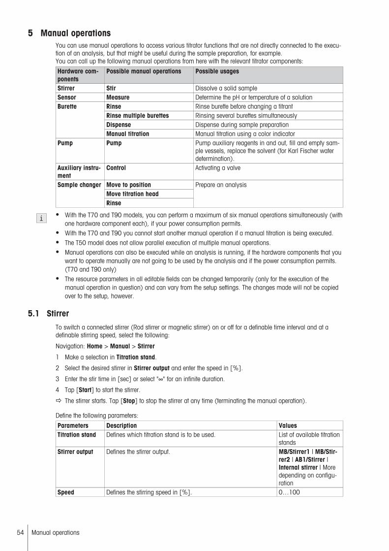
5 Manual operationsYou can use manual operations to access various titrator functions that are not directly connected to the execution of an analysis, but that might be useful during the sample preparation, for example.You can call up the following manual operations from here with the relevant titrator components:
Hardware components
Possible manual operations Possible usages
Stirrer Stir Dissolve a solid sampleSensor Measure Determine the pH or temperature of a solution
Rinse Rinse burette before changing a titrantRinse multiple burettes Rinsing several burettes simultaneouslyDispense Dispense during sample preparation
Burette
Manual titration Manual titration using a color indicatorPump Pump Pump auxiliary reagents in and out, fill and empty sam
ple vessels, replace the solvent (for Karl Fischer waterdetermination).
Auxiliary instrument
Control Activating a valve
Move to positionMove titration head
Sample changer
Rinse
Prepare an analysis
● With the T70 and T90 models, you can perform a maximum of six manual operations simultaneously (withone hardware component each), if your power consumption permits.
● With the T70 and T90 you cannot start another manual operation if a manual titration is being executed.● The T50 model does not allow parallel execution of multiple manual operations.● Manual operations can also be executed while an analysis is running, if the hardware components that you
want to operate manually are not going to be used by the analysis and if the power consumption permits.(T70 and T90 only)
● The resource parameters in all editable fields can be changed temporarily (only for the execution of themanual operation in question) and can vary from the setup settings. The changes made will not be copiedover to the setup, however.
5.1 StirrerTo switch a connected stirrer (Rod stirrer or magnetic stirrer) on or off for a definable time interval and at adefinable stirring speed, select the following:
Navigation: Home > Manual > Stirrer
1 Make a selection in Titration stand.
2 Select the desired stirrer in Stirrer output and enter the speed in [%].
3 Enter the stir time in [sec] or select "∞" for an infinite duration.
4 Tap [Start] to start the stirrer.
The stirrer starts. Tap [Stop] to stop the stirrer at any time (terminating the manual operation).
Define the following parameters:
Parameters Description ValuesTitration stand Defines which titration stand is to be used. List of available titration
standsStirrer output Defines the stirrer output. MB/Stirrer1 | MB/Stir
rer2 | AB1/Stirrer |Internal stirrer | Moredepending on configuration
Speed Defines the stirring speed in [%]. 0…100
54 Manual operations

Stir time The stirring time, in [sec], during which the stirrer should be inoperation. Select "∞" for unlimited stirring time.
0…104 | ∞
● Entries made here will only be applied to the manual operation and will have no effect on the instrumentsettings.
5.2 SensorTo take a measurement using any connected sensor, select the following:
Navigation: Home > Manual > Sensor
1 Make a selection in Sensor.
2 Select the desired stirrer and enter a speed.
3 For polarized, potentiometric and conductivity sensors, specify whether the temperature should be enteredmanually or automatically.
4 For manual temperature acquisition, enter the temperature.- or -For automatic temperature acquisition, select a connected temperature sensor and the temperature unit to beused.
5 Enter the duration of the measurement in [sec] or select "∞" for an infinite duration.
6 Select whether to output a record on the printer.
7 To output a record on the printer, use dt [sec] to define the time interval between measurements.
8 Tap [Start] to start the measurement.
The measurement starts. Tap [Stop] to stop the measurment at any time (terminating the manual operation).
During the measurement, the system will display the online curve (measured values in the selected unit versus time). Use [Measured values] to display a table of measured values instead of the curve.
5.2.1 Temperature sensor
You can define the following parameters for a manual operation:
Parameters Description ValuesSensor Select a sensor from the list. The list depends on the sensor type
selected in Type.List of available sensors
Sensor input The input to which you want to connect the sensor. AB1/PT1000 | Moredepending on configuration
Unit The unit of measure to be used for the measurement; the unit willdepend on the sensor type selected.
°C | K | °F
Titration stand Defines which titration stand is to be used. List of available titrationstands
Stirrer output Defines the stirrer output. MB/Stirrer1 | MB/Stirrer2 | AB1/Stirrer |Internal stirrer | Moredepending on configuration
Speed Defines the stirring speed in [%]. 0…100Duration The measurement and stirring time, in [sec]. Select "∞" for
unlimited measurement time.0…104 | ∞
Record If activated, the measured values will be printed out. Yes | Nodt Defines the time interval in [sec] for outputting measured values
to the printer.Only appears if Record = Yes was selected.
1…6000
55Manual operations

● Entries made here will only be applied to the manual operation and will have no effect on the instrumentsettings.
5.2.2 Potentiometric Sensor
You can define the following parameters for a manual operation:
Potentiometric sensors are potentiometric indicator electrode, such as glass electrodes for pH measurement,Redox electrode for measuring the redox potential or ion-selective electrodes (ISE) for determining of ion contentin the solution. Below, the editable parameters are listed for both potentiometric sensors and photrodes used forturbidimetric and color induced titrations:
Parameters Description ValuesSensor Select a sensor from the list. The list depends on the sensor type
selected in Type.List of available sensors
Sensor input The input to which you want to connect the sensor. AB1/Sensor1 |AB1/Sensor2 |AB1/PT1000 |CB1/Conductivity |More depending onconfiguration
Unit The unit of measure to be used for the measurement; the unit willdepend on the sensor type selected.
mV | pH | pM | A | %T
Titration stand Defines which titration stand is to be used. List of available titrationstands
Stirrer output Defines the stirrer output. MB/Stirrer1 | MB/Stirrer2 | AB1/Stirrer |Internal stirrer | Moredepending on configuration
Speed Defines the stirring speed in [%]. 0…100Temperaturemanual
Defines whether to enter the temperature manually (Yes) or via atemperature sensor (No).
Yes | No
Temperature If the temperature is entered manually, you can enter it here, in[°C].Only appears if Temperature manual = Yes was selected.
-20…200
Temperaturesensor
Here you can select the required temperature sensor.Only appears if Temperature manual = No is selected.
List of available sensors
Sensor input The input to which you want to connect the sensor. AB1/Sensor1 |AB1/Sensor2 |AB1/PT1000 |CB1/Conductivity |More depending onconfiguration
Temperatureunit
The unit of measure for the temperature measurement.Only appears if Temperature manual = No was selected.
°C | K | °F
Duration The measurement and stirring time, in [sec]. Select "∞" forunlimited measurement time.
0…104 | ∞
Record If activated, the measured values will be printed out. Yes | Nodt Defines the time interval in [sec] for outputting measured values
to the printer.Only appears if Record = Yes was selected.
1…6000
● The parameters for temperature acquisition or entering the temperature, Temperature manual,Temperature, Temperature sensor, Sensor input and Temperature unit are omitted for mV sensors andthe phototrode.
● Entries made here will only be applied to the manual operation and will have no effect on the instrumentsettings.
56 Manual operations
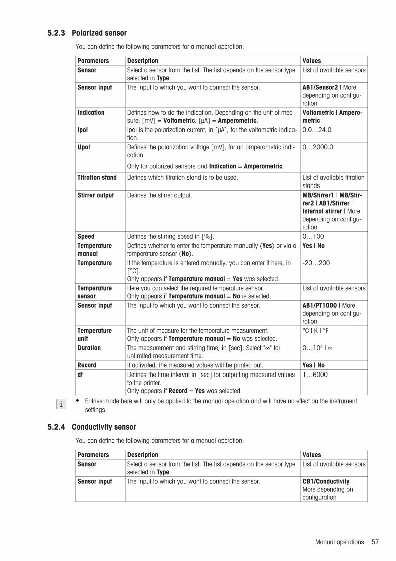
5.2.3 Polarized sensor
You can define the following parameters for a manual operation:
Parameters Description ValuesSensor Select a sensor from the list. The list depends on the sensor type
selected in Type.List of available sensors
Sensor input The input to which you want to connect the sensor. AB1/Sensor2 | Moredepending on configuration
Indication Defines how to do the indication. Depending on the unit of measure: [mV] = Voltametric, [µA] = Amperometric.
Voltametric | Amperometric
Ipol Ipol is the polarization current, in [µA], for the voltametric indication.
0.0…24.0
Upol Defines the polarization voltage [mV], for an amperometric indication.
Only for polarized sensors and Indication = Amperometric.
0…2000.0
Titration stand Defines which titration stand is to be used. List of available titrationstands
Stirrer output Defines the stirrer output. MB/Stirrer1 | MB/Stirrer2 | AB1/Stirrer |Internal stirrer | Moredepending on configuration
Speed Defines the stirring speed in [%]. 0…100Temperaturemanual
Defines whether to enter the temperature manually (Yes) or via atemperature sensor (No).
Yes | No
Temperature If the temperature is entered manually, you can enter it here, in[°C].Only appears if Temperature manual = Yes was selected.
-20…200
Temperaturesensor
Here you can select the required temperature sensor.Only appears if Temperature manual = No is selected.
List of available sensors
Sensor input The input to which you want to connect the sensor. AB1/PT1000 | Moredepending on configuration
Temperatureunit
The unit of measure for the temperature measurement.Only appears if Temperature manual = No was selected.
°C | K | °F
Duration The measurement and stirring time, in [sec]. Select "∞" forunlimited measurement time.
0…104 | ∞
Record If activated, the measured values will be printed out. Yes | Nodt Defines the time interval in [sec] for outputting measured values
to the printer.Only appears if Record = Yes was selected.
1…6000
● Entries made here will only be applied to the manual operation and will have no effect on the instrumentsettings.
5.2.4 Conductivity sensor
You can define the following parameters for a manual operation:
Parameters Description ValuesSensor Select a sensor from the list. The list depends on the sensor type
selected in Type.List of available sensors
Sensor input The input to which you want to connect the sensor. CB1/Conductivity |More depending onconfiguration
57Manual operations

Unit Defines the unit of measure to be used for the measurement. µS/cm | mS/cm | µS |mS
Titration stand Defines which titration stand is to be used. List of available titrationstands
Stirrer output Defines the stirrer output. MB/Stirrer1 | MB/Stirrer2 | AB1/Stirrer |Internal stirrer | Moredepending on configuration
Speed Defines the stirring speed in [%]. 0…100Temperaturemanual
Defines whether to enter the temperature manually (Yes) or via atemperature sensor (No).
Yes | No
Temperature If the temperature is entered manually, you can enter it here, in[°C].Only appears if Temperature manual = Yes was selected.
-20…200
Temperaturesensor
Here you can select the required temperature sensor.Only appears if Temperature manual = No is selected.
List of available sensors
Sensor input The input to which you want to connect the sensor. AB1/PT1000 | Moredepending on configuration
Temperatureunit
The unit of measure for the temperature measurement.Only appears if Temperature manual = No was selected.
°C | K | °F
Duration The measurement and stirring time, in [sec]. Select "∞" forunlimited measurement time.
0…104 | ∞
Record If activated, the measured values will be printed out. Yes | Nodt Defines the time interval in [sec] for outputting measured values
to the printer.Only appears if Record = Yes was selected.
1…6000
● Entries made here will only be applied to the manual operation and will have no effect on the instrumentsettings.
5.3 BuretteIn this window, carry out various manual operations with the available burettes.
Rinse an available burette or rinse multiple burettes at the same time, dispense a defined quantity of titrant orrun a manual titration with a selected burette.
Navigation: Home > Manual > Burette
5.3.1 Rinse burette
Navigation: Home > Manual > Burette > Rinse
This operation lets you rinse a burette and its connecting tubes and fill it with fresh titrant, for example if youwant to remove air bubbles from the system.
1 Select the titrant you want to rinse with.
2 Select the drive on which the titrant is installed. (For PnP burettes, the system automatically selects theappropriate drive.)
3 Enter the number of cycles you want to run.
4 Enter the discharge volume in [%] to define the percentage of the burette's total volume that you want todischarge during each rinse passage.
5 Enter the filling rate in [%] to define the speed at which you want to refill the burette. (100% is the maximum rate.)
6 Tap [Start] to start the procedure.
The procedure starts. Tap [Stop] to stop the procedure at any time.
58 Manual operations
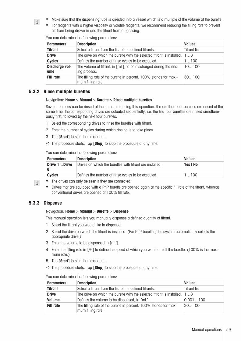
● Make sure that the dispensing tube is directed into a vessel which is a multiple of the volume of the burette.● For reagents with a higher viscosity or volatile reagents, we recommend reducing the filling rate to prevent
air from being drawn in and the titrant from outgassing.
You can determine the following parameters:
Parameters Description ValuesTitrant Select a titrant from the list of the defined titrants. Titrant listDrive The drive on which the burette with the selected titrant is installed. 1…8Cycles Defines the number of rinse cycles to be executed. 1…100Discharge volume
The volume of titrant, in [mL], to be discharged during the rinsing process.
10…100
Fill rate The filling rate of the burette in percent. 100% stands for maximum filling rate.
30…100
5.3.2 Rinse multiple burettes
Navigation: Home > Manual > Burette > Rinse multiple burettes
Several burettes can be rinsed at the same time using this operation. If more than four burettes are rinsed at thesame time, the corresponding drives are actuated sequentially, i.e. the first four burettes are rinsed simultaneously first, followed by the next four burettes.
1 Select the corresponding drives to rinse the burettes with titrant.
2 Enter the number of cycles during which rinsing is to take place.
3 Tap [Start] to start the procedure.
The procedure starts. Tap [Stop] to stop the procedure at any time.
You can determine the following parameters:
Parameters Description ValuesDrive 1…Drive8
Drives on which the burettes with titrant are installed. Yes | No
Cycles Defines the number of rinse cycles to be executed. 1…100● The drives can only be seen if they are connected.● Drives that are equipped with a PnP burette are opened again at the specific fill rate of the titrant, whereas
conventional drives are opened at 100% fill rate.
5.3.3 Dispense
Navigation: Home > Manual > Burette > Dispense
This manual operation lets you manually dispense a defined quantity of titrant.
1 Select the titrant you would like to dispense.
2 Select the drive on which the titrant is installed. (For PnP burettes, the system automatically selects theappropriate drive.)
3 Enter the volume to be dispensed in [mL].
4 Enter the filling rate in [%] to define the speed at which you want to refill the burette. (100% is the maximum rate.)
5 Tap [Start] to start the procedure.
The procedure starts. Tap [Stop] to stop the procedure at any time.
You can determine the following parameters:
Parameters Description ValuesTitrant Select a titrant from the list of the defined titrants. Titrant listDrive The drive on which the burette with the selected titrant is installed. 1…8Volume Defines the volume to be dispensed, in [mL]. 0.001…100Fill rate The filling rate of the burette in percent. 100% stands for maxi
mum filling rate.30…100
59Manual operations
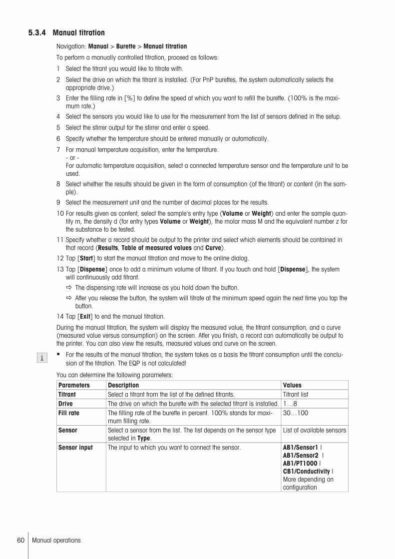
5.3.4 Manual titration
Navigation: Manual > Burette > Manual titration
To perform a manually controlled titration, proceed as follows:
1 Select the titrant you would like to titrate with.
2 Select the drive on which the titrant is installed. (For PnP burettes, the system automatically selects theappropriate drive.)
3 Enter the filling rate in [%] to define the speed at which you want to refill the burette. (100% is the maximum rate.)
4 Select the sensors you would like to use for the measurement from the list of sensors defined in the setup.
5 Select the stirrer output for the stirrer and enter a speed.
6 Specify whether the temperature should be entered manually or automatically.
7 For manual temperature acquisition, enter the temperature.- or -For automatic temperature acquisition, select a connected temperature sensor and the temperature unit to beused.
8 Select whether the results should be given in the form of consumption (of the titrant) or content (in the sample).
9 Select the measurement unit and the number of decimal places for the results.
10 For results given as content, select the sample's entry type (Volume or Weight) and enter the sample quantity m, the density d (for entry types Volume or Weight), the molar mass M and the equivalent number z forthe substance to be tested.
11 Specify whether a record should be output to the printer and select which elements should be contained inthat record (Results, Table of measured values and Curve).
12 Tap [Start] to start the manual titration and move to the online dialog.
13 Tap [Dispense] once to add a minimum volume of titrant. If you touch and hold [Dispense], the systemwill continuously add titrant.
The dispensing rate will increase as you hold down the button.
After you release the button, the system will titrate at the minimum speed again the next time you tap thebutton.
14 Tap [Exit] to end the manual titration.
During the manual titration, the system will display the measured value, the titrant consumption, and a curve(measured value versus consumption) on the screen. After you finish, a record can automatically be output tothe printer. You can also view the results, measured values and curve on the screen.
● For the results of the manual titration, the system takes as a basis the titrant consumption until the conclusion of the titration. The EQP is not calculated!
You can determine the following parameters:
Parameters Description ValuesTitrant Select a titrant from the list of the defined titrants. Titrant listDrive The drive on which the burette with the selected titrant is installed. 1…8Fill rate The filling rate of the burette in percent. 100% stands for maxi
mum filling rate.30…100
Sensor Select a sensor from the list. The list depends on the sensor typeselected in Type.
List of available sensors
Sensor input The input to which you want to connect the sensor. AB1/Sensor1 |AB1/Sensor2 |AB1/PT1000 |CB1/Conductivity |More depending onconfiguration
60 Manual operations

Unit The unit of measure to be used for the measurement; the unit willdepend on the sensor type selected.
mV | pH | pM | pX |ppm | %T | A | µA | °C |K | °F | µS/cm | mS/cm |µS | mS
Indication Defines how to do the indication. Depending on the unit of measure: [mV] = Voltametric, [µA] = Amperometric.
Voltametric | Amperometric
Ipol Ipol is the polarization current, in [µA], for the voltametric indication.
0.0…24.0
Upol Defines the polarization voltage [mV], for an amperometric indication.
Only for polarized sensors and Indication = Amperometric.
0…2000.0
Titration stand Defines which titration stand is to be used. List of available titrationstands
Stirrer output Defines the stirrer output. MB/Stirrer1 | MB/Stirrer2 | AB1/Stirrer |Internal stirrer | Moredepending on configuration
Speed Defines the stirring speed in [%]. 0…100Temperaturemanual
Defines whether to enter the temperature manually (Yes) or via atemperature sensor (No).
Yes | No
Temperature If the temperature is entered manually, you can enter it here, in[°C].Only appears if Temperature manual = Yes was selected.
-20…200
Temperaturesensor
Here you can select the required temperature sensor.Only appears if Temperature manual = No is selected.
List of available sensors
Sensor input The input to which you want to connect the sensor. AB1/Sensor1 |AB1/Sensor2 |AB1/PT1000 |CB1/Conductivity |More depending onconfiguration
Temperatureunit
The unit of measure for the temperature measurement.Only appears if Temperature manual = No was selected.
°C | K | °F
Result Select whether to output the result of the manual titration as theamount of titrant consumed or as the content in the sample.
Consumption | Content
Unit The unit for stating the result in the form of the titrant consumption.Only for Result = Consumption.
mL | mmol
Unit The unit for stating the result as the sample content.Only for Result = Content.
mol/L | mol/kg | g/L |g/kg | % | ppm
Decimal places Specify the required number of decimal places for the results. 1...4Entry type The entry type for the sample size.
Only for Result = ContentWeight | Volume
Sample size The sample size, in [mL] or in [g], depending on the entry typeselected.Only for Result = Content.
0.0001…100
Density The density of the sample substance to be determined, in [g/mL].Only for Result = Content.
0.0001…100
M Defines the molar mass of the substance [g/mol]. List of concentration/titer standards andsubstances
Record Defines whether to output a record to the printer after the titration. Yes | NoIncl. result Here you can specify whether the record should contain all the
results.Only appears for Record = Yes.
Yes | No
61Manual operations

Incl. table ofmeasured values
Here you can specify whether the record should contain a table ofmeasured values.Only appears for Record = Yes.
Yes | No
Incl. curve Here you can specify whether the record should contain a curve.Only appears for Record = Yes.
Yes | No
● The parameters for temperature acquisition or entering the temperature, Temperature manual,Temperature, Temperature sensor, Sensor input and Temperature unit are omitted for mV sensors andthe phototrode.
5.4 PumpNavigation: Home > Manual > Pump
This manual operation will use a connected pump to pump in any volume of auxiliary reagent or - dependingon the connection of the tubes - to drain it from the titration vessel.
Proceed as follows to start a pump process:
1 Select the pump and adjust the pum rate.
2 Enter the volume in [mL] to be added.
3 Tap [Start] to start the procedure.
The procedure starts. Tap [Stop] to stop the procedure at any time.
You can determine the following parameters:
Parameters Description ValuesAction Determines the actions for the pump process. Pumps | When using
the Karl Fischer SolventManager: Drain | Fill |Replace Solvent
Auxiliaryreagent
The auxiliary reagent to be added. List of available auxiliary reagents
Pump Use this setting to select a pump. List of available pumpsMax. pump rate Displays the defined pump rate in [mL/min] as defined in the set
tings. Changing this value does not change the rate of the pump,only the time calculated for the addition.
0.1…1000
Pump output The output where you want to operate the pump. MB/PUMP1 |MB/PUMP2 |AB1/PUMP | Moredepending on configuration
Volume The volume to be dispensed, in [mL]. Select "∞" for unlimitedpumping.
0…1000 | ∞
Pump property Defines the properties for the pump used. 1-way | 1-way, tworates | 2-way, fine rate
Rate Allows to reduce the pump rate.Only if the pump supports this and if the pump is connected toan InMotion.
10…100 (2-way, finerate) | 50/100 (1-way,two rates)
Direction Defines the pump direction for a 2-way pump Forward | ReverseDrain time Defines the pumping time for draining a fluid.
The duration of the drain operation for the tubes should be aslong as possible to ensure that the tubes are completely free ofliquids following draining.
0...1000 | ∞
Fill time Defines the pumping time for filling a liquid. 0...1000 | ∞Reset counter If this parameter is set, all counters are reset when cell filling
commences (applies to current capacity per number of samples). The fill date for the cell is also reset.
Yes | No
Stirrer A stirrer can be switched on.Only for Action = Fill or Drain.
Yes | No
62 Manual operations

Titration stand The name of the titration stand.only if stirrer is activated.
List of titration stands
Stirrer output Specifies the stirrer output at the relevant board (only available ifStirrer is activated).
Internal stirrer | Moredepending on configuration
Speed Speed in [%].Only if stirrer is activated.
0…100
5.5 Auxiliary instrumentNavigation: Home > Manual > Auxiliary instrument
Selectively control here the titrator's inputs and outputs. You can transmit outgoing signals and query incomingsignals. This lets you check whether the communication is functioning between the titrator and a connectedauxiliary instrument (lid handler, dispenser, etc.). In this way, manually triggered auxiliary instrument functionscan be used as support for a titration.
To activate an auxiliary instrument, proceed as follows:
1 In Control type, select the auxiliary instrument to be controlled.
2 Enter the specific communication parameters for the control type.
3 Tap [Start] to start the procedure.
The procedure starts. Tap [Stop] to stop the procedure at any time.
● For Control type = Stirrer, you may use a second stirrer simultaneously to a stirrer started by the manualoperation Stirrer. (Only for the T70 and T90)
The following parameters are available, depending on the type:
Parameters Description ValuesControl type The control type of the auxiliary instrument. Output 24 V | Stirrer |
Out TTL (Single pin) |Input TTL (Single pin) |TTL (Multipin) |RS-232
For Control type = Output 24 V, the following parameters are available:Parameters Description ValuesName Select the auxiliary instrument to be controlled from the list. Auxiliary instrumentOutput Indicates which port on the titrator you want to use for the auxil
iary instrument.MB/PUMP1 |MB/PUMP2 |AB1/PUMP | Moredepending on configuration
Duration The time, in [sec], the auxiliary instrument should be switchedon. Select "∞" for unlimited time.
0…104 | ∞
● An auxiliary instrument controlled by the control type Output 24 V can be switched on and off or operatedfor a defined period of time.
For Control type = Out TTL (Single pin), the following parameters are available:Parameters Description ValuesName Select the auxiliary instrument to be controlled from the list. Auxiliary instrumentOutput Indicates which port on the titrator you want to use for the auxil
iary instrument.MB/PUMP1 |MB/PUMP2 |AB1/PUMP | Moredepending on configuration
63Manual operations

Mode Determines the number and type of TTL signal issued.Fixed time: The control output is switched on for the defined timeperiod.Input controlled: A signal received at the control inlet controls thecontrol outlet. The Auxiliary Instrument function will be terminatedas soon as the signal changes at the control inlet or after adefined maximum time has expired.Sequential: The control output runs through a defined sequence.
Fixed time | Input controlled | Sequential
Duration The time, in [sec], the auxiliary instrument should be switchedon. Select "∞" for unlimited time.
0…104 | ∞
Input aux. instr. The name of the auxiliary instrument to serve as the signal input(control input).Only appears for Mode = Input controlled.
List of auxiliary instrument
Input The input where the auxiliary instrument should be queried.Only appears for Mode = Input controlled.
MB/TTL-In 1 | MB/TTL-In 2
Max. wait time The maximum waiting time for a signal change.Only appears for Mode = Input controlled.
0…104 | ∞
Output signal Normal: The signal is transmitted without conversion.Inverted: The signal is transmitted in inverted form.
Only if Mode = Input controlled.
Normal | Inverted
Number of pulses
The number of impulses in the planned sequence.
Only if Mode = Sequential.
0…104
Pulse duration The duration of a pulse, in [sec].Only appears for Mode = Sequential.
0…104
Interval Defines the time span, in [sec], between two impulse starts.
Only if Mode = Sequential.
0…106 | 0…104
● If Mode = Input controlled was selected, the system checks the incoming input signal until the maximumtime expires or a signal is received.
For Control type = Input TTL (Single pin), the following parameters are available:Parameters Description ValuesName Select the auxiliary instrument to be controlled from the list. Auxiliary instrumentInput The input where the auxiliary instrument should be queried.
Only appears for Mode = Input controlled.MB/TTL-In 1 | MB/TTL-In 2
Input signal Indicates whether an rising or a falling input signal should bedetected.
Rising | Falling
Max. wait time The maximum waiting time for a signal change.Only appears for Mode = Input controlled.
0…104 | ∞
● Use the control type Input TTL (Single pin) to wait for a rising or falling input signal. The manual operationwill be ended as soon as an input signal is received or the maximum waiting time is exceeded.
For Control type = Stirrer, the following parameters are available:
Parameters Description ValuesName Select the auxiliary instrument to be controlled from the list. Auxiliary instrumentSpeed Defines the stirring speed in [%]. 0…100Output Indicates which port on the titrator you want to use for the auxil
iary instrument.MB/PUMP1 |MB/PUMP2 |AB1/PUMP | Moredepending on configuration
Duration The time, in [sec], the auxiliary instrument should be switchedon. Select "∞" for unlimited time.
0…104 | ∞
64 Manual operations
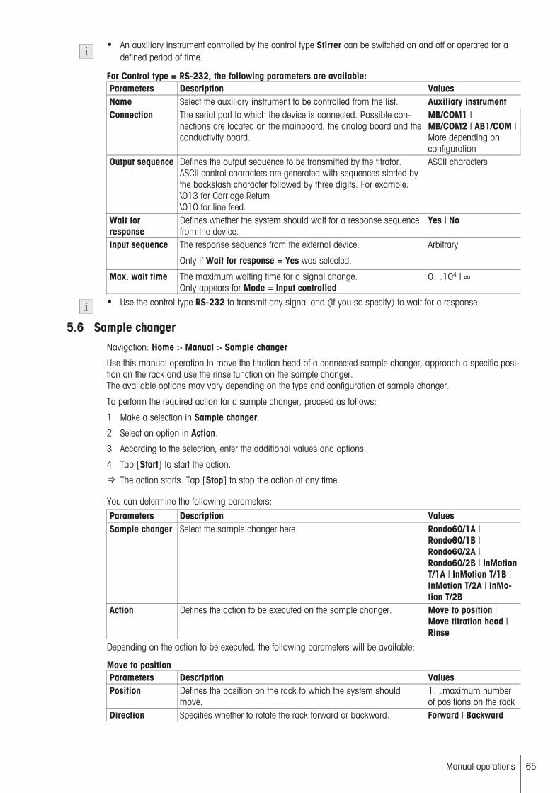
● An auxiliary instrument controlled by the control type Stirrer can be switched on and off or operated for adefined period of time.
For Control type = RS-232, the following parameters are available:Parameters Description ValuesName Select the auxiliary instrument to be controlled from the list. Auxiliary instrumentConnection The serial port to which the device is connected. Possible con
nections are located on the mainboard, the analog board and theconductivity board.
MB/COM1 |MB/COM2 | AB1/COM |More depending onconfiguration
Output sequence Defines the output sequence to be transmitted by the titrator.ASCII control characters are generated with sequences started bythe backslash character followed by three digits. For example:\013 for Carriage Return\010 for line feed.
ASCII characters
Wait forresponse
Defines whether the system should wait for a response sequencefrom the device.
Yes | No
Input sequence The response sequence from the external device.
Only if Wait for response = Yes was selected.
Arbitrary
Max. wait time The maximum waiting time for a signal change.Only appears for Mode = Input controlled.
0…104 | ∞
● Use the control type RS-232 to transmit any signal and (if you so specify) to wait for a response.
5.6 Sample changerNavigation: Home > Manual > Sample changer
Use this manual operation to move the titration head of a connected sample changer, approach a specific position on the rack and use the rinse function on the sample changer.The available options may vary depending on the type and configuration of sample changer.
To perform the required action for a sample changer, proceed as follows:
1 Make a selection in Sample changer.
2 Select an option in Action.
3 According to the selection, enter the additional values and options.
4 Tap [Start] to start the action.
The action starts. Tap [Stop] to stop the action at any time.
You can determine the following parameters:
Parameters Description ValuesSample changer Select the sample changer here. Rondo60/1A |
Rondo60/1B |Rondo60/2A |Rondo60/2B | InMotionT/1A | InMotion T/1B |InMotion T/2A | InMotion T/2B
Action Defines the action to be executed on the sample changer. Move to position |Move titration head |Rinse
Depending on the action to be executed, the following parameters will be available:
Move to positionParameters Description ValuesPosition Defines the position on the rack to which the system should
move.1…maximum numberof positions on the rack
Direction Specifies whether to rotate the rack forward or backward. Forward | Backward
65Manual operations

Titration headposition
The vertical position to which the titration head of the samplechanger should be brought.Cond. measure: This position is 20 mm above the Sample position and is intended to immerse the conductivity sensor into thesample but not the pH sensor, preventing electrolyte contamination from the pH sensor.Only available with InMotion.
Sample | Rotate |Rinse | Cond. measure
Move titration headMove here the sample changer's titration head to one of possible vertical positions.
Parameters Description ValuesTitration headposition
The vertical position to which the titration head of the samplechanger should be brought.Cond. measure: This position is 20 mm above the Sample position and is intended to immerse the conductivity sensor into thesample but not the pH sensor, preventing electrolyte contamination from the pH sensor.Only available with InMotion.
Sample | Rotate |Rinse | Cond. measure
RinseThe sensors, stirrer, tubes, etc. on a sample changer can be rinsed, with or without draining the rinse liquid.
Parameters Description ValuesAuxiliaryreagent
The auxiliary reagent to be added. List of available auxiliary reagents
Pump Use this setting to select a pump. List of available pumpsMax. pump rate Displays the defined pump rate in [mL/min] as defined in the set
tings. Changing this value does not change the rate of the pump,only the time calculated for the addition.
0.1…1000
Pump output The output where you want to operate the pump. MB/PUMP1 |MB/PUMP2 |AB1/PUMP | Moredepending on configuration
Rinse cycles The number of rinse cycles to be run. 1…100Vol. per cycle The rinse volume in [mL] per cycle. 0…1000Position Defines the position on the rack to which the system should
move.1…maximum numberof positions on the rack
Drain Defines whether to drain the rinse liquid. Yes | NoDrain pump Defines which pump is to be used for drainage. List of available pumpsMax. pump rate Displays the defined pump rate in [mL/min] as defined in the set
tings. Changing this value does not change the rate of the pump,only the time calculated for the addition.
0.1…1000
Pump output The output where you want to operate the pump. MB/PUMP1 |MB/PUMP2 |AB1/PUMP | Moredepending on configuration
See also
● Solvent Control (page 49)
66 Manual operations

6 MethodsTo carry out an analysis with the titrator, you require a method. A method is an analysis program and consistsof a sequence of method functions (some with method subfunctions), which are processed by the titrator insequence.
In this chapter, you will learn how to access and define methods.
The basic building blocks of a titration method consist of sample preparation, stirring and wait times, the actualtitration, result calculation and a record. The titrator defines these partial steps as functions that consist of parameters whose values can be changed.
LoopsDepending on the device type, a method can contain one or more loops (see Method Syntax - Rules for Creating a Method (page 73)"). The ranges of a method through which several samples will pass are defined usinga "loop". The method functions before and after a loop are each conducted only once, even if an analysis contains several samples.
The beginning and end of a sample loop are defined by the method functions "Sample" and "End of Sample".The "End of Sample" method function is executed, and the sample loop stopped, only after the last sample in aseries.
There are the following loop types:
● A sample loop is for analyzing a sample.● A calibration loop is for calibrating a sensor.● A titer loop is for determining the titer of a titrant.
Types of MethodsThe titrator distinguishes between the following method types with different objectives:
● GTMethod for general titration (contains only sample loops or mixed loops)
● Calibrationmethod for sensor calibration (contains only calibration loops).
● TiterMethod for titer determination, contains only titer loops
● KF-VolMethod for volumetric water content determination with the Karl Fischer method.
● External Extraction"External extraction" is a KF method for samples with extremely inhomogeneous water dissipation. It is alsoused for insoluble solids which only release water slowly, even if broken into smaller pieces.
● StromboliMethod for selecting the Stromboli oven sample changer as the titration stand.
Preloaded MethodsA number of methods have already been stored in the device. These methods were developed by METTLERTOLEDO for specific uses and can be used immediately for the corresponding analysis.
You can change these methods in line with your requirements and save them as user methods.
When creating methods you can revert to method templates, which, according to their objective, specify thestructure of the method, and whose parameters already contain the most suitable default values.
For a list of preloaded methods, see the appendix: METTLER-TOLEDO Methods (page 68).
Method IDYou can distinguish between different types of method and individual methods of the same type using their ID:
● Each method has its own unique method identification.● The method ID of the Mettler methods is composed of the starting letter "M", or "KFV" for volumetric Karl Fis
cher titration, followed by a sequential number. (M001, M002, …or KFV01, KFV02...)● The method ID for a user method can be chosen at random, however it cannot begin with an "M" followed
by a number.
67Methods

See also
● METTLER TOLEDO Methods (page 68)
6.1 METTLER TOLEDO MethodsMETTLER TOLEDO methods are preprogrammed methods for executing specific applications. These methodsare stored in the device prior to shipping (Methods List) and can be started immediately by the user. METTLERmethods not only provide the sequence of the method functions, but they also define all of the method functionsettings. A METTLER method can be saved as a user method by saving it under a different method ID.
METTLER TOLEDO methods: GTID Title Description Titrant SensorM400 Acetic acid in vinegar EQP titration NaOH DG111M401 Ammonium chloride content EQP titration NaOH DG111M402 Free fatty acid content EQP titration KOH in Ethanol DG113M403 Blank solvent FFA EQP titration KOH in Ethanol DG113M404 Chloride content in Ketchup EQP titration AgNO3 DM141M405 Total hardness of tap water EQP titration EDTA DP5M406 Ca + Mg content of tap water EQP titration EDTA Ca ISEM407 Sulfate content EQP titration BaCl2 Ba ISEM408 Barium content conductometric EQP titration Li2SO4 InLab717M409 Copper content EQP titration Na2S2
O3
DM140
M410 Hydrogen peroxide content EQP titration KMnO4 DM140M411 Vitamin C content voltametric EQP titration DPI DM143M412 Vitamin C content amperometric EQP titration DPI DM143M413 SDS content photometric EQP titration Hyamine DP5M414 SDS content potentiometric EQP titration Hyamine DS500M415 m-Value of tap water (EP) EP titration HCl DG111M416 p-Value of tap water (EP) EP titration NaOH DG111M417 Antacid (Stating) pH stating NaOH DG111M418 HCl content (EP) EP titration NaOH DG111M419 Free SO2 content in wine (EP) EP titration I2 DM143M420 Water content KF (EP) EP titration Composite 5 DM143M421 Titer KF (EP) EP titration Composite 5 DM143M422 Drift KF (EP) EP titration Composite 5 DM143M423 Standby KF (EP) EP titration Composite 5 DM143M424 Bromine number ASTM D1159
(EP)EP titration Bromide, bromate DM143
M425 Blank ASTM D1159 (EP) EP titration Bromide, bromate DM143M426 Acid number ASTM D664 EQP titration KOH in 2-propanol DG113M427 Blank ASTM D664 (EP) EP titration KOH in 2-propanol DG113M428 Base number ASTM D4739 EQP titration HCl in 2-propanol DG113M429 Blank ASTM D4739 EQP titration HCl in 2-propanol DG113M430 Base number ASTM D2896 EQP titration HClO4 in acetic acid DG113M431 Blank ASTM D2896 EQP titration HClO4 in acetic acid DG113M432 Chloride content in motor oil EQP titration AgNO3 in
2-propanolDM141
M433 Mercaptan sulfur ASTM D3227 EQP titration AgNO3 in2-propanol
DM141
M434 SDS content (2-phase) 2P titration Hyamine 1622 DP5M435 Titer 0.1 mol/L NaOH EQP titration 0.1M NaOH DG111M436 Calibration DG111-SC Measure - DG111-SCM437 HCl content conductometric EQP titration NaOH InLab717
68 Methods

ID Title Description Titrant SensorM449 Nitrogen Kjeldahl with K-360 EQP-Titration 1/2 H2SO4 DG111-SCM451 Liquid Handler with Tx Liquid Handler: Prepare,
Aspirate und Dispense- -
M454 Nitrogen Kjeldahl TTL EP-Titration 1/2 H2SO4 DG111-SCM455 Nitrogen Kjeldahl Manual EP-Titration 1/2 H2SO4 DG111-SCM657 Parallel preparation-titration EQP titration AgNO3 DM141M659 COND+pH 100mL water bath
25°Measure NA InLab 731,
DG111M660 Aliquoting + LH - 25mL tubes
AliquotEQP Titration NaOH DG111
METTLER TOLEDO methods: GT for T90ID Title Description Titrant SensorM400 Acetic acid in vinegar EQP titration NaOH DG111M401 Ammonium chloride content EQP titration NaOH DG111M658A Parallel titration Tower A EQP titration NaOH DG111M658B Parallel titr. T/1B - Master EQP titration AgNO3 DM141
M658B Parallel titr. T/1B - Master EQP titration AgNO3 DM141
METTLER TOLEDO methods: KF VolID Title Description Titrant SensorM300 Water standard 10.0 mg/g KFVol KF 1-comp | KF
2-compDM143-SC
M301 Di-Sodium-Tartrate 15.660% KFVol KF 1-comp | KF2-comp
DM143-SC
M302 Toluene dry KFVol KF 1-comp | KF2-comp
DM143-SC
M303 Acetone dry KFVol KF 1-comp | KF2-comp
DM143-SC
M304 Milk powder (homogenizer) KFVol KF 1-comp | KF2-comp
DM143-SC
M305 Tobacco (external extraction) KFVol external extraction KF 1-comp | KF2-comp
DM143-SC
M306 Corn starch (manual oven) KFVol KF 1-comp | KF2-comp
DM143-SC
M307 Air (gaseous samples) KFVol KF 1-comp | KF2-comp
DM143-SC
M311 Water standard tablet 10 mg KFVol KF 1-comp | KF2-comp
DM143-SC
M312 Oven stand. 5.55% (Stromboli) KFVol Stromboli KF 1-comp | KF2-comp
DM143-SC
M313 Temp. ramp (Stromboli) KFVol Stromboli KF 1-comp | KF2-comp
DM143-SC
● Sensor: DM143-SC
● Titrant: KF 1-comp | KF 2-comp
6.2 Creating MethodsYou create a new method by changing the parameters of a delivered METTLER method and saving it under anew method ID or by selecting an appropriate method template from the list of proposals, modifying it, andsaving it under a new ID.
Navigation: Home > Methods
1 Tap [New] to create a new method on the basis of a template.
2 From the available templates, choose the one that is most similar to the method you wish to create.
69Methods

You can now modify this method in line with your requirements by inserting or removing method functions or modifying its parameters.
3 In the method function Title, enter a new method ID. Afterwards, a new method will be stored under thismethod ID.
4 Assign a title to your new method.
5 Select available method functions to modify their parameters in line with your requirements.
6 Tap [Insert] to add additional method functions to the template.
7 Now use the arrow-shaped button to select the required position for the new method function in the method.(You will only be able to insert the method functions that are allowed in the corresponding location basedon the method syntax.)
8 From the list, select the method function that you want to insert.
9 Modify the individual parameters of the method function in line with the resources.
The new method function appears in the method.
10 To delete a method function, select the function in question and then tap [Delete].
The method function disappears from the method.
11 After inserting all required method functions, tap [Save].
The method is saved under the method ID and appears in the list of available methods.
● When establishing a new method, follow the rules specified by the instrument.
See also
● Method Syntax – Rules for Establishing a Method (page 73)
6.2.1 Method Templates
When you create a new method, the method templates prescribe the sequence of the method functions. Thesemethod templates are not application-specific, but are dependent on the type of titrator. They allow the user toestablish user methods quickly and easily. Most of the settings in the method functions that occur in a standardmethod already have default values.
To convert a method template into a user method, it has to be saved under a method ID.
Title Type of instrument Method typeEQP T50/T70/T90 General titrationEP T50/T70/T90 General titrationStating T50/T70/T90 General titrationMeasure T50/T70/T90 General titration2-phase T50/T70/T90 General titrationLearn-EQP T50/T70/T90 General titrationEQP detection T50/T70/T90 General titrationTiter with EQP T50/T70/T90 Titer determinationTiter with EP T50/T70/T90 Titer determinationCalibration T50/T70/T90 CalibrationSegmented calibration T50/T70/T90 CalibrationBlank with EQP T50/T70/T90 General titrationBlank with EP T50/T70/T90 General titrationEP/EQP T50/T70/T90 General titrationEQP/EQP T50/T70/T90 General titrationEP/EP T50/T70/T90 General titrationTiter with EQP & EQP T70/T90 General titrationTiter with EP & EP T70/T90 General titrationCalibration & EQP T70/T90 General titrationCalibration & EP T70/T90 General titrationCalibration & titer with EQP & EQP T70/T90 General titration
70 Methods

Calibration & titer with EP & EP T70/T90 General titration
6.3 Modifying or Deleting MethodsYou can change user methods or METTLER methods and store them under new method IDs.
Once a METTLER method has been modified, you will only be able to save it as a copy (or as a user method)with a new method ID.
Modifying a methodTo modify a method, select:
Home > Methods
1 From the displayed list of methods, select the method that you want to modify.
2 As soon as the methods functions of the selected method appear on the screen, you can modify themethod.
3 In the "Title" method function, enter a new method ID. Afterwards, a new method will be stored under thismethod ID. You can enter up to twenty alphanumeric characters.
4 Select available method functions to modify their parameters in line with your requirements.
5 Choose Insert to add additional method functions to the template.
6 Now use the arrow-shaped "Insert" button to select the required position for the new method function in themethod. (You will only be able to insert the method functions that are allowed in the corresponding locationbased on the method syntax.)
7 From the list, select the method function that you want to insert.
8 Modify the individual parameters of the method function.
The new method function appears in the method.
1 To delete a method function, select the function in question and then choose Delete.
2 After you have made all of the necessary adjustments, you can store the method in the titrator by choosingSave.
Deleting MethodsYou can easily delete user-defined methods from the titrator. Select:
Home > Methods
1 Select the method that you want to delete.
2 Choose Delete method to delete the method from the titrator's memory.
6.4 Starting MethodsThe titrator offers various ways of starting a method:
● From the method editor● By choosing Start from the Home dialog● By using a shortcut on the Home screen● Via the Series dialog● By using the "Setup" dialog (to perform a calibration or titer determination)
You can use the method editor to start any method stored in the titrator.
1 From the displayed list in the Methods dialog, select the method that you wish to start (Home > Methods).
2 As soon as the method functions of the selected method appear on the screen, you can open the Startanalysis screen by choosing Start.
3 Choose Start again to reach an overview screen on the resources required for the method. (Only if this wasdefined in the analysis sequence settings.)
4 To execute the method, confirm the screen by choosing OK.
71Methods

6.5 Stopping MethodsAnalyses or series of analyses that are in progress can be interrupted or terminated by the user in order to intervene in the analysis process or by the titrator itself.
The options available in the event of an interruption of the analysis procedure are listed below.
6.5.1 Suspending an ongoing analysis by the user
If you wish to make changes when an analysis or series is in progress, you can suspend the relevant methodas follows:
– Tap [Suspend].
The following options appear:
Save series data
The complete series assigned to the interrupted analysis is saved as a file in the form "SeriesXY".
● If the maximum permitted number of series has been reached, the series is not saved.● Sample data from a method that is waiting in a queue can be saved by selecting Suspend > Save series
data.
Skip sample
The analysis continues with the next sample. The current sample is marked in Results as Excl..
Skip loop
The analysis omits the current sample loop and continues with the next one. The loop is marked in Results asExcl..
● This method function is only available for selection if a sample from any given loop was being analyzed atthe time of the interruption. If a Calib. loop is skipped, the analysis continues in accordance with the corresponding method function Calibration.
● The samples that have been skipped are automatically excluded from the statistics. This applies to allresults for the sample; also those that were listed before the sample was skipped. If required, you can stilluse the Results dialog to include the sample in the statistics once the analysis is complete.
Further, you can decide whether you wish to stop or continue the analysis:
– To do so, choose Continue to continue the analysis or Stop definitely to stop the suspended analysis.
See also
● Series Templates (page 129)● Series Templates (page 129)
6.5.2 Interrupting an ongoing analysis by the titrator
The titrator can suspend an analysis that is in progress for the following reasons:
● Due to an instructionAs soon as the method function Instruction has been processed, the analysis continues.
● Due to the monitoring actions for the method function Stating or Dispense (controlled)The analysis is interrupted if in the sub-function Monitoring the parameter Action = Manual is selected andthe sensor signal exceeds or falls below the specified upper or lower limit. In this case, you have the optionto either cancel or continue the titration. Once the titration is canceled, the analysis continues with the nextsample. If Action = Automatic was selected, the titration is also interrupted in this case if the sensor signal exceedsor falls below the specified upper or lower limit. The titration is continued automatically when the sensorsignal lies within the specified limits once again.
● Exceeding the specified termination parameters of the sub function Termination for the method functionsTitration (EP) and Titration (EQP).
72 Methods
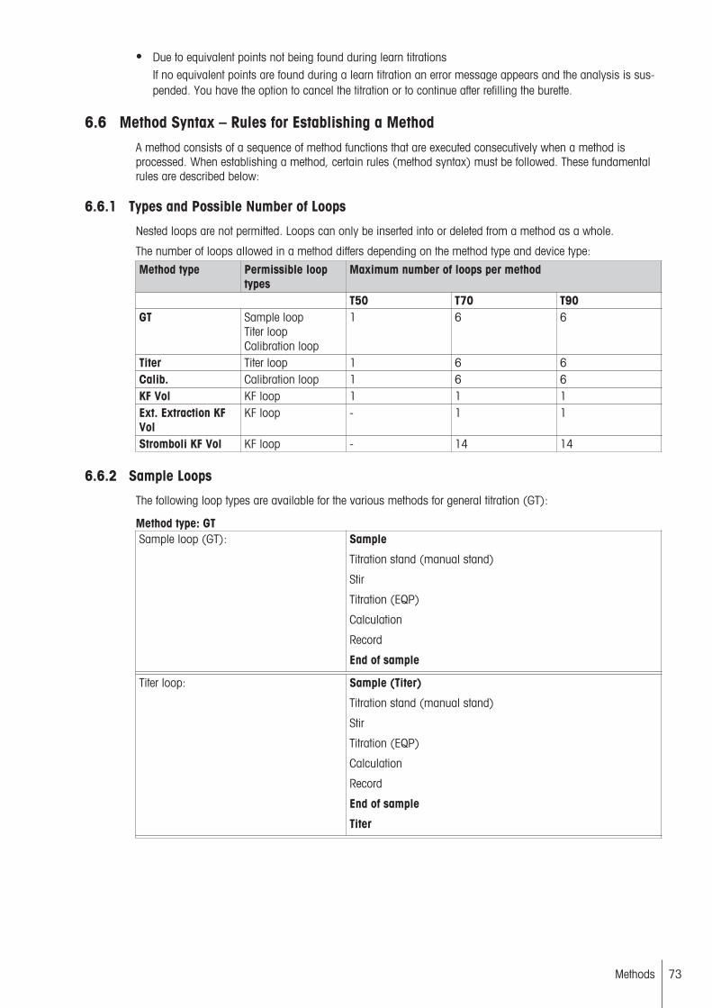
● Due to equivalent points not being found during learn titrationsIf no equivalent points are found during a learn titration an error message appears and the analysis is suspended. You have the option to cancel the titration or to continue after refilling the burette.
6.6 Method Syntax – Rules for Establishing a MethodA method consists of a sequence of method functions that are executed consecutively when a method isprocessed. When establishing a method, certain rules (method syntax) must be followed. These fundamentalrules are described below:
6.6.1 Types and Possible Number of Loops
Nested loops are not permitted. Loops can only be inserted into or deleted from a method as a whole.
The number of loops allowed in a method differs depending on the method type and device type:
Method type Permissible looptypes
Maximum number of loops per method
T50 T70 T90GT Sample loop
Titer loopCalibration loop
1 6 6
Titer Titer loop 1 6 6Calib. Calibration loop 1 6 6KF Vol KF loop 1 1 1Ext. Extraction KFVol
KF loop - 1 1
Stromboli KF Vol KF loop - 14 14
6.6.2 Sample Loops
The following loop types are available for the various methods for general titration (GT):
Method type: GTSample loop (GT): Sample
Titration stand (manual stand)
Stir
Titration (EQP)
Calculation
Record
End of sample
Titer loop: Sample (Titer)
Titration stand (manual stand)
Stir
Titration (EQP)
Calculation
Record
End of sample
Titer
73Methods

Calibration loop: Sample (calibration)
Titration stand (manual stand)
Stir
Measure (normal)
End of sample
Calibration
Method type "Stromboli (KFVol)"The following template is available for this method type:
KF sample loop with blank valueSample loop (KF): Sample (KF)
Titration stand (Stromboli)
Mix time
Titration (KF Vol)
Calculation
Record
End of sample
Blank
6.6.3 Inserting and Deleting Loops
The following description applies particularly for the GT method type.
Complete loops cannot be inserted or deleted for Karl Fischer methods, with the exception of the "Stromboli"method type.
For method type "GT"Only entire loops can be inserted into or deleted from a method.
When you insert a loop using the "Sample", "Sample (Titer)", and "Sample (Calib)" method functions, a regular, correct template that varies according to the loop type is inserted:
When deleting one of the stored method functions listed above in gray, the entire loop will be deleted from themethod, including all of the method functions it contains.
6.7 Overview of method functions
For method type: GT
Functions Explanation Inside loop Outside loopTitle Title and characteristics of the method. No YesSample Start of a sample loop.Sample (Titer) Start of a loop for titer determinationSample (Calibration) Start of a loop for sensor calibration.
Start of loop
Titration stand Selects titration stand. Yes NoLine rinse Rinse the lines of an InMotion sample
changer.Yes Yes
Liquid Handling Performs aspirating or dispensing functions.
Yes Yes
Mix time Duration of the mixing process This valueis gained from experience. It can beentered specifically for each sample.
Yes No
Rinse Rinsing function for a sensor or stirrer. Yes YesConditioning Conditioning function for sample changer. Yes YesPumps Pumps a defined volume of a liquid. Yes Yes
74 Methods
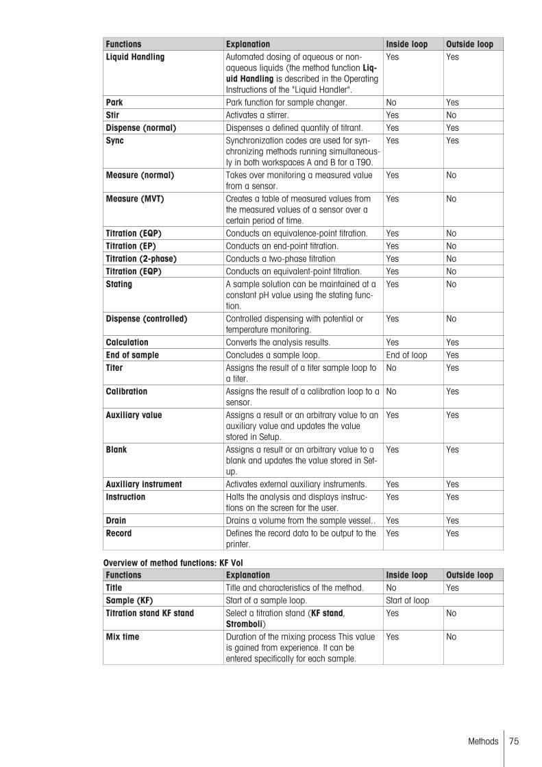
Functions Explanation Inside loop Outside loopLiquid Handling Automated dosing of aqueous or non-
aqueous liquids (the method function Liquid Handling is described in the OperatingInstructions of the "Liquid Handler".
Yes Yes
Park Park function for sample changer. No YesStir Activates a stirrer. Yes NoDispense (normal) Dispenses a defined quantity of titrant. Yes YesSync Synchronization codes are used for syn
chronizing methods running simultaneously in both workspaces A and B for a T90.
Yes Yes
Measure (normal) Takes over monitoring a measured valuefrom a sensor.
Yes No
Measure (MVT) Creates a table of measured values fromthe measured values of a sensor over acertain period of time.
Yes No
Titration (EQP) Conducts an equivalence-point titration. Yes NoTitration (EP) Conducts an end-point titration. Yes NoTitration (2-phase) Conducts a two-phase titration Yes NoTitration (EQP) Conducts an equivalent-point titration. Yes NoStating A sample solution can be maintained at a
constant pH value using the stating function.
Yes No
Dispense (controlled) Controlled dispensing with potential ortemperature monitoring.
Yes No
Calculation Converts the analysis results. Yes YesEnd of sample Concludes a sample loop. End of loop YesTiter Assigns the result of a titer sample loop to
a titer.No Yes
Calibration Assigns the result of a calibration loop to asensor.
No Yes
Auxiliary value Assigns a result or an arbitrary value to anauxiliary value and updates the valuestored in Setup.
Yes Yes
Blank Assigns a result or an arbitrary value to ablank and updates the value stored in Setup.
Yes Yes
Auxiliary instrument Activates external auxiliary instruments. Yes YesInstruction Halts the analysis and displays instruc
tions on the screen for the user.Yes Yes
Drain Drains a volume from the sample vessel.. Yes YesRecord Defines the record data to be output to the
printer.Yes Yes
Overview of method functions: KF VolFunctions Explanation Inside loop Outside loopTitle Title and characteristics of the method. No YesSample (KF) Start of a sample loop. Start of loopTitration stand KF stand Select a titration stand (KF stand,
Stromboli)Yes No
Mix time Duration of the mixing process This valueis gained from experience. It can beentered specifically for each sample.
Yes No
75Methods
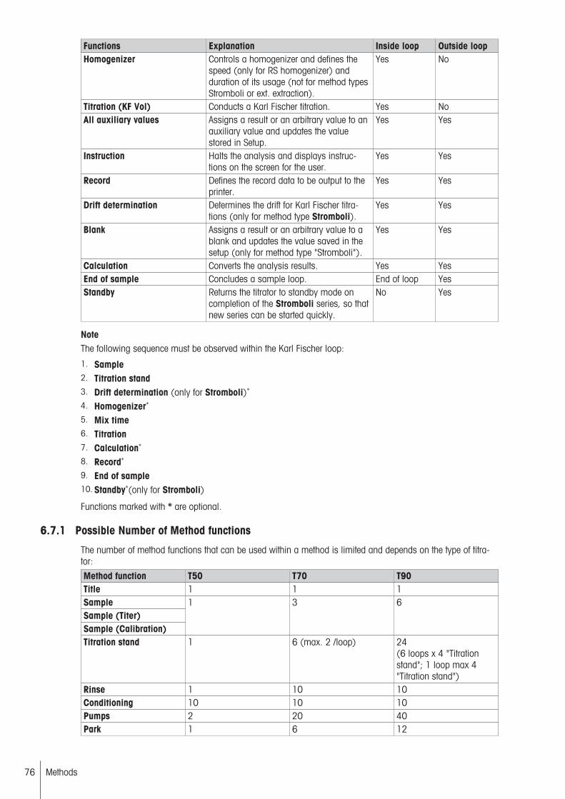
Functions Explanation Inside loop Outside loopHomogenizer Controls a homogenizer and defines the
speed (only for RS homogenizer) andduration of its usage (not for method typesStromboli or ext. extraction).
Yes No
Titration (KF Vol) Conducts a Karl Fischer titration. Yes NoAll auxiliary values Assigns a result or an arbitrary value to an
auxiliary value and updates the valuestored in Setup.
Yes Yes
Instruction Halts the analysis and displays instructions on the screen for the user.
Yes Yes
Record Defines the record data to be output to theprinter.
Yes Yes
Drift determination Determines the drift for Karl Fischer titrations (only for method type Stromboli).
Yes Yes
Blank Assigns a result or an arbitrary value to ablank and updates the value saved in thesetup (only for method type "Stromboli").
Yes Yes
Calculation Converts the analysis results. Yes YesEnd of sample Concludes a sample loop. End of loop YesStandby Returns the titrator to standby mode on
completion of the Stromboli series, so thatnew series can be started quickly.
No Yes
NoteThe following sequence must be observed within the Karl Fischer loop:
1. Sample2. Titration stand3. Drift determination (only for Stromboli)*
4. Homogenizer*
5. Mix time6. Titration7. Calculation*
8. Record*
9. End of sample10. Standby*(only for Stromboli)
Functions marked with * are optional.
6.7.1 Possible Number of Method functions
The number of method functions that can be used within a method is limited and depends on the type of titrator:
Method function T50 T70 T90Title 1 1 1SampleSample (Titer)Sample (Calibration)
1 3 6
Titration stand 1 6 (max. 2 /loop) 24(6 loops x 4 "Titrationstand"; 1 loop max 4"Titration stand")
Rinse 1 10 10Conditioning 10 10 10Pumps 2 20 40Park 1 6 12
76 Methods
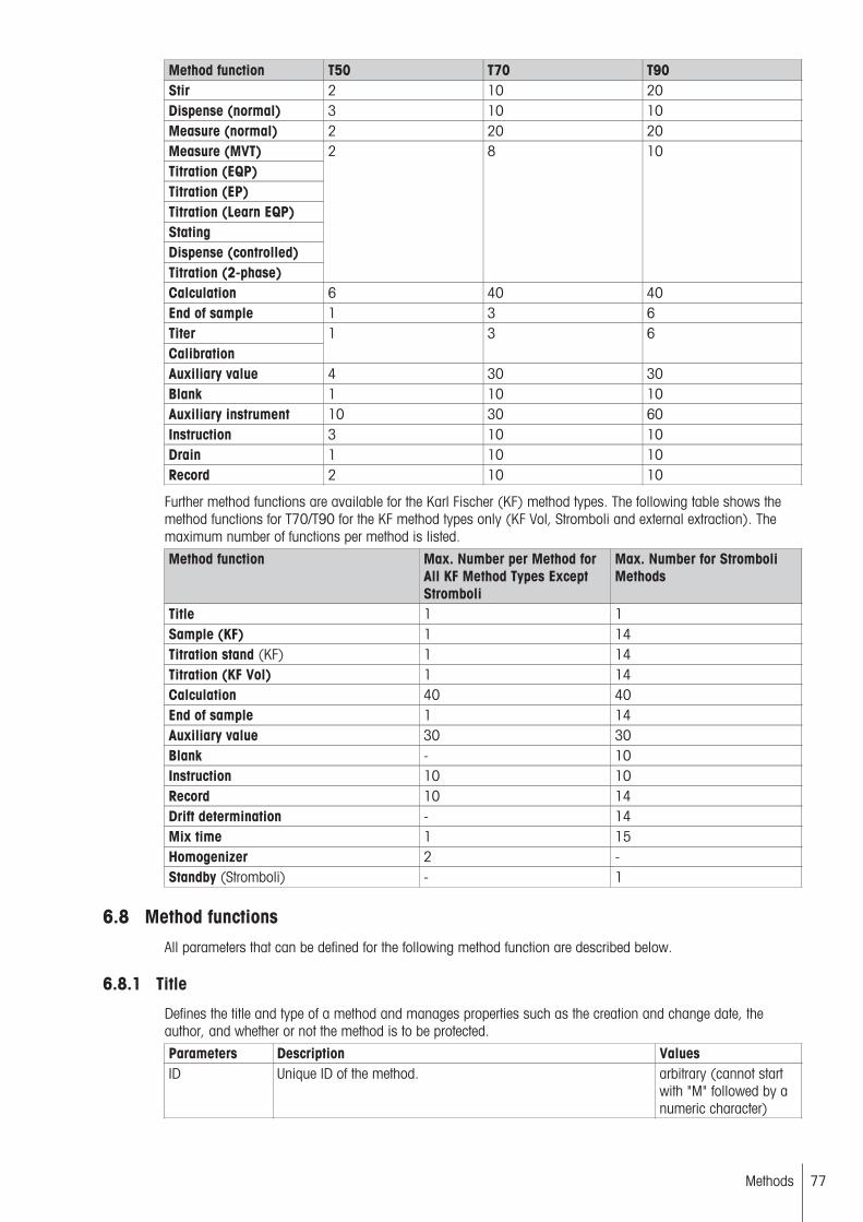
Method function T50 T70 T90Stir 2 10 20Dispense (normal) 3 10 10Measure (normal) 2 20 20Measure (MVT)Titration (EQP)Titration (EP)Titration (Learn EQP)StatingDispense (controlled)Titration (2-phase)
2 8 10
Calculation 6 40 40End of sample 1 3 6TiterCalibration
1 3 6
Auxiliary value 4 30 30Blank 1 10 10Auxiliary instrument 10 30 60Instruction 3 10 10Drain 1 10 10Record 2 10 10
Further method functions are available for the Karl Fischer (KF) method types. The following table shows themethod functions for T70/T90 for the KF method types only (KF Vol, Stromboli and external extraction). Themaximum number of functions per method is listed.
Method function Max. Number per Method forAll KF Method Types ExceptStromboli
Max. Number for StromboliMethods
Title 1 1Sample (KF) 1 14Titration stand (KF) 1 14Titration (KF Vol) 1 14Calculation 40 40End of sample 1 14Auxiliary value 30 30Blank - 10Instruction 10 10Record 10 14Drift determination - 14Mix time 1 15Homogenizer 2 -Standby (Stromboli) - 1
6.8 Method functionsAll parameters that can be defined for the following method function are described below.
6.8.1 Title
Defines the title and type of a method and manages properties such as the creation and change date, theauthor, and whether or not the method is to be protected.
Parameters Description ValuesID Unique ID of the method. arbitrary (cannot start
with "M" followed by anumeric character)
77Methods

Title Title of the method. ArbitraryProtect Protects the method against changes and
deletion by any user other than the author or the administrator.Yes | No
SOP Standard operating procedure(SOP: (SOP)
None | Text | Link
SOP-Text Text for a standard operating procedure(if "SOP" = "text" is selected.)
Arbitrary text
SOP ID ID for the link to a standard operating procedure (if "SOP" = "link"is selected.)
Arbitrary
6.8.2 Sample
The "Sample" and "End of sample" method functions define the beginning and the end of a sample loop. All ofthe method functions contained in a loop are conducted for each sample in a series. The method functions areconducted in accordance with "End of Sample" only after processing the last sample.
Parameters Description ValuesNumber of IDs Defines the number of sample IDs to be defined. 1…3ID 1 The ID for the first or only sample of an analysis. ArbitraryID 2…ID 3 The name defined here will be used as the default name for the
respective sample on the sample loop.Only appears subject to the settings made for Number of IDs.
Arbitrary
Entry type Defines whether the sample should be added with a definedmass, defined volume or defined number of pieces. The sampledata query will then adjust according to the unit of measurement.Fixed volume or Fixed pieces: The sampling weight, samplevolume or number of pieces will be entered as the parameter inthis method function and will not be prompted when conductingthe method.
Weight | Fixed weight |Volume | Fixedvolume | Pieces | Fixedpieces
Lower limit Defines the lower limit for the variable entry data. The unit willdepend on the setting for Entry type parameter.Only appears if none fixed values are selected in Entry type.
[g]: 0 … 1000[mL]: 0 … 1000[pcs.]: 0 … 106
Upper limit Defines the upper limit for the variable entry of data. The unit willdepend on the setting for Entry type parameter.Only appears if none fixed values are selected in Entry type.
[g]: 0 … 1000[mL]: 0 … 1000[St.]: 0 … 106
Weight Weight in [g].Appears only if Entry type = Fixed weight was selected.
0…1000
Volume Volume in [mL].Appears only if Entry type = Fixed volume was selected.
0…1000
Pieces The number of sample(s).Appears only if Entry type = Fixed pieces was selected.
0…106
Weight perpiece
The weight in [g] per pirece.Appears only if Entry type = Pieces or Fixed pieces was selected.
0 … 1000
Density The density of a liquid sample substance, in [g/mL].Appears only if Entry type = Weight, Volume, Fixed weight orFixed volume was selected.
0.0001…100
Correction factor Any correction factor that can be used in calculations. 0.0001…106
Temperature The temperature in [°C] during the analysis. If temperature monitoring is activated in a titration function, the system will ignorethe sample temperature given here.
-20…200
Entry Determines the entry time for the sample size.Before: The sample size must be entered before the titration.Arbitrary: The sample size will have to be entered at any timeduring the titration (no later than when it is used during the calculations).Only appears if none fixed values are selected in Entry type.
Before | Arbitrary
78 Methods

Sample datareader
None: no sample data reader is used.RFID: sample ID1,2, sample size, density and factor are readfrom the RFID tag on the beaker.MT 2D barcode: sample ID1 and sample size are read from thebarcode (this is a MT specific barcode layout).ID 1 barcode: the barcode string is used as sample ID1.Only appears for Titration stand = InMotion.
RFID, MT 2D barcode ,ID 1 barcode | None
6.8.3 Sample (titer)
Start of a loop for titer determination Contains all of the necessary data regarding the titrant and the standard tobe used.
Parameters Description ValuesTitrant Select a titrant from the list of the defined titrants. Titrant listStandard Select the name of the standard from the standards list. Select from the stan
dards defined in the setup.
Entry type Defines whether the quantity (weight or volume) of a liquid orsolid standard should be entered when the analysis is started orwhether a Fixed weight or a Fixed volume should be defined inthe method function.
Weight | Fixed weight |Volume | Fixedvolume | Pieces | Fixedpieces
Lower limit Defines the lower limit for the variable entry of sample data in[mL] or [g]. The unit will depend on the setting for Entry typeparameter.Applies only for Entry type = Weight and Volume.
0...1000
Upper limit Defines the upper limit for the variable entry of data. The unit willdepend on the setting for Entry type parameter.Only appears if none fixed values are selected in Entry type.
[g]: 0 … 1000[mL]: 0 … 1000[St.]: 0 … 106
Weight Weight in [g].Appears only if Entry type = Fixed weight was selected.
0…1000
Volume Volume in [mL].Appears only if Entry type = Fixed volume was selected.
0…1000
Correction factor Any correction factor that can be used in calculations. 0.0001…106
Temperature The temperature in [°C] during the analysis. If temperature monitoring is activated in a titration function, the system will ignorethe sample temperature given here.
-20…200
Entry Determines the entry time for the sample size.Before: The sample size must be entered before the titration.Arbitrary: The sample size will have to be entered at any timeduring the titration (no later than when it is used during the calculations).Only appears if none fixed values are selected in Entry type.
Before | Arbitrary
Sample datareader
None: no sample data reader is used.RFID: sample ID1,2, sample size, density and factor are readfrom the RFID tag on the beaker.MT 2D barcode: sample ID1 and sample size are read from thebarcode (this is a MT specific barcode layout).ID 1 barcode: the barcode string is used as sample ID1.Only appears for Titration stand = InMotion.
RFID, MT 2D barcode ,ID 1 barcode | None
6.8.4 Sample (calibration)
Start of a loop for sensor calibration. Contains all of the necessary data regarding the sensor and the calibrationstandard.
Parameters Description ValuesSensor type Specifies the type of sensor that is calibrated pH | ISE | Conductivity |
TemperatureSensor Select a sensor from the list. The list depends on the sensor type
selected in Type.List of available sensors
79Methods
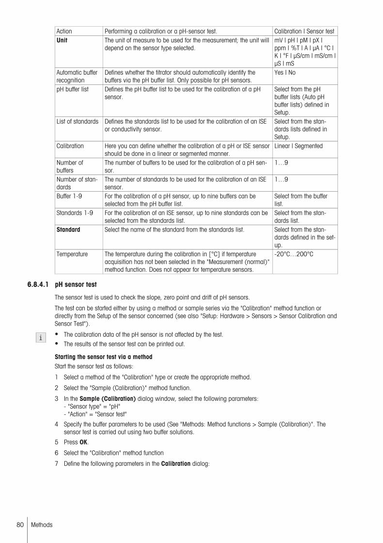
Action Performing a calibration or a pH-sensor test. Calibration | Sensor testUnit The unit of measure to be used for the measurement; the unit will
depend on the sensor type selected.mV | pH | pM | pX |ppm | %T | A | µA | °C |K | °F | µS/cm | mS/cm |µS | mS
Automatic bufferrecognition
Defines whether the titrator should automatically identify thebuffers via the pH buffer list. Only possible for pH sensors.
Yes | No
pH buffer list Defines the pH buffer list to be used for the calibration of a pHsensor.
Select from the pHbuffer lists (Auto pHbuffer lists) defined inSetup.
List of standards Defines the standards list to be used for the calibration of an ISEor conductivity sensor.
Select from the standards lists defined inSetup.
Calibration Here you can define whether the calibration of a pH or ISE sensorshould be done in a linear or segmented manner.
Linear | Segmented
Number ofbuffers
The number of buffers to be used for the calibration of a pH sensor.
1…9
Number of standards
The number of standards to be used for the calibration of an ISEsensor.
1…9
Buffer 1-9 For the calibration of a pH sensor, up to nine buffers can beselected from the pH buffer list.
Select from the bufferlist.
Standards 1-9 For the calibration of an ISE sensor, up to nine standards can beselected from the standards list.
Select from the standards list.
Standard Select the name of the standard from the standards list. Select from the standards defined in the setup.
Temperature The temperature during the calibration in [°C] if temperatureacquisition has not been selected in the "Measurement (normal)"method function. Does not appear for temperature sensors.
-20°C…200°C
6.8.4.1 pH sensor test
The sensor test is used to check the slope, zero point and drift of pH sensors.
The test can be started either by using a method or sample series via the "Calibration" method function ordirectly from the Setup of the sensor concerned (see also "Setup: Hardware > Sensors > Sensor Calibration andSensor Test").
● The calibration data of the pH sensor is not affected by the test.● The results of the sensor test can be printed out.
Starting the sensor test via a methodStart the sensor test as follows:
1 Select a method of the "Calibration" type or create the appropriate method.
2 Select the "Sample (Calibration)" method function.
3 In the Sample (Calibration) dialog window, select the following parameters:- "Sensor type" = "pH"- "Action" = "Sensor test"
4 Specify the buffer parameters to be used (See "Methods: Method functions > Sample (Calibration)". Thesensor test is carried out using two buffer solutions.
5 Press OK.
6 Select the "Calibration" method function
7 Define the following parameters in the Calibration dialog:
80 Methods

Parameters Description ValuesInterruption outside limits
Determines whether the method should be interrupted if a valuelies outside the defined limits (only appears if the "Limits" parameter has been activated).A message (which must be acknowledged) appears advisingthat the process has been interrupted during the time that themessage is displayed.
Yes | No
Min. slope 1-8 The lower limit for the slope, in [%]. (100% refers to -59.16mV/pH.)
10…200
Max. slope 1-8 The upper limit for the slope, in [%]. 10…200Min. zero point1-8
The lower limit for the zero point. -100…100
Max. zero point1-8
The upper limit for the zero point. -100…100
Min. drift The minimum drift value in [mV/30s]. -100 to 100Max. drift The maximum drift value in [mV/30s]. -100 to 100● If the values are within the limits, the sensor test is regarded as having been passed.● Slope and drift relate to 25°C.
To provide an overview, the relevant method functions have been summarized and listed in the following table:
Method functions for the pH sensor testMethod function DescriptionSample (Calibration) This method function is used firstly in order to carry out a calibration and
secondly for the sensor test. It is selected via the "Action" parameter. Onlytwo buffers can be defined for the sensor test.
Measure (normal) The measured values of both calibration solutions (pH buffers) are determined here. In addition, another drift determination is carried out for the second buffer.
Calibration In the method, the "Calibration" method function for the sensor test is placedafter the "End of sample" method function. Essentially, "Calibration" corresponds to a calculation function. In the process, it calculates the calibrationparameters from the measured values of the calibration loop and the calibration standard values (pH buffer values). These are then compared withthe inputted limit values for the zero point, slope and drift.
Record The results of the sensor test are displayed in the "Overview" section of therecord. The various selection parameters for titration curves (E – V, dE/dV –V, etc.) which are available during standard titration are invalid for therecord.
6.8.5 Sample (KF)
The method function Sample (KF) for Karl Fischer titration is subdivided into the subfunctions Sample, Concentration, and Blank values (only for external extraction). You can define the following parameters:
Subfunction: SampleParameters Description ValuesNumber of IDs Defines the number of sample IDs to be defined. 1…3ID 1…ID 3 The name defined here will be used as the default name for the
respective sample on the sample loop.Only appears subject to the settings made in Number of IDs.
Arbitrary
Entry type Defines whether the sample should be added with a definedmass, defined volume or defined number of pieces. The sampledata query will then adjust according to the unit of measurement.Fixed volume or Fixed pieces: The sampling weight, samplevolume or number of pieces will be entered as the parameter inthis method function and will not be prompted when conductingthe method.
Weight | Fixed weight |Volume | Fixedvolume | Pieces | Fixedpieces
81Methods
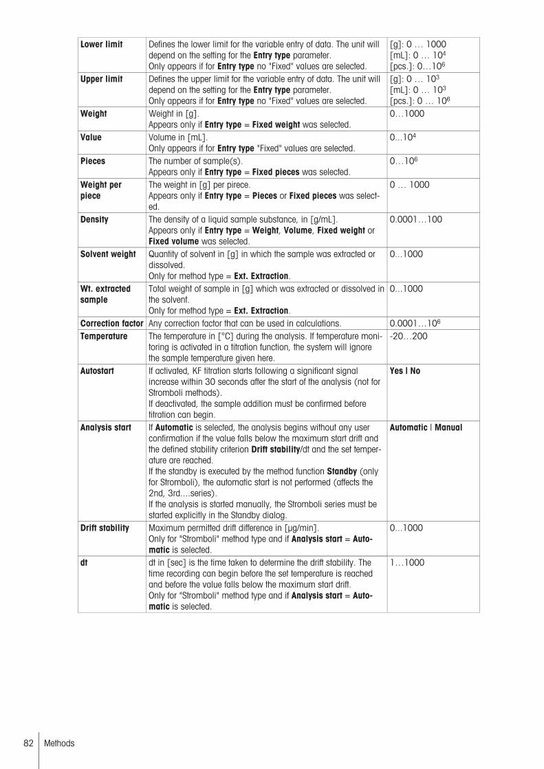
Lower limit Defines the lower limit for the variable entry of data. The unit willdepend on the setting for the Entry type parameter.Only appears if for Entry type no "Fixed" values are selected.
[g]: 0 … 1000[mL]: 0 … 104
[pcs.]: 0…106
Upper limit Defines the upper limit for the variable entry of data. The unit willdepend on the setting for the Entry type parameter.Only appears if for Entry type no "Fixed" values are selected.
[g]: 0 … 103
[mL]: 0 … 103
[pcs.]: 0 … 106
Weight Weight in [g].Appears only if Entry type = Fixed weight was selected.
0…1000
Value Volume in [mL].Only appears if for Entry type "Fixed" values are selected.
0...104
Pieces The number of sample(s).Appears only if Entry type = Fixed pieces was selected.
0…106
Weight perpiece
The weight in [g] per pirece.Appears only if Entry type = Pieces or Fixed pieces was selected.
0 … 1000
Density The density of a liquid sample substance, in [g/mL].Appears only if Entry type = Weight, Volume, Fixed weight orFixed volume was selected.
0.0001…100
Solvent weight Quantity of solvent in [g] in which the sample was extracted ordissolved.Only for method type = Ext. Extraction.
0...1000
Wt. extractedsample
Total weight of sample in [g] which was extracted or dissolved inthe solvent.Only for method type = Ext. Extraction.
0...1000
Correction factor Any correction factor that can be used in calculations. 0.0001…106
Temperature The temperature in [°C] during the analysis. If temperature monitoring is activated in a titration function, the system will ignorethe sample temperature given here.
-20…200
Autostart If activated, KF titration starts following a significant signalincrease within 30 seconds after the start of the analysis (not forStromboli methods).If deactivated, the sample addition must be confirmed beforetitration can begin.
Yes | No
Analysis start If Automatic is selected, the analysis begins without any userconfirmation if the value falls below the maximum start drift andthe defined stability criterion Drift stability/dt and the set temperature are reached.If the standby is executed by the method function Standby (onlyfor Stromboli), the automatic start is not performed (affects the2nd, 3rd....series).If the analysis is started manually, the Stromboli series must bestarted explicitly in the Standby dialog.
Automatic | Manual
Drift stability Maximum permitted drift difference in [µg/min].Only for "Stromboli" method type and if Analysis start = Automatic is selected.
0...1000
dt dt in [sec] is the time taken to determine the drift stability. Thetime recording can begin before the set temperature is reachedand before the value falls below the maximum start drift.Only for "Stromboli" method type and if Analysis start = Automatic is selected.
1…1000
82 Methods

Entry Determines the input time for the sample size.Before: The sample size must be entered before the titration.Arbitrary: The sample size will have to be entered at any timeduring the titration (no later than when it is used during the calculations). Only appears if for Entry type no "Fixed" values areselected.After addition: You are prompted to enter the sample data oncethe sample has been added. The sample size - even during themethod execution - can be entered later on (however, no laterthan when required for use in formulas).
Arbitrary | After addition
Subfunction: ConcentrationTo correctly determine the water content of a sample, the concentration of the titrant should be determined usingKarl Fischer water standards. The concentration determination is performed using control and termination parameters.Any predispensing defined in the method is not performed. A defined blank value is also not taken into accountin the calculation. Following a concentration determination, the system always switches to standby mode toenable double and multiple determinations.The concentration determination can be started manually. You can start the concentration determination of theKF titrant from Standby of any Karl Fischer (KF) method. You can determine the following parameters:
Parameters Description ValuesStandard Select the name of the standard from the standards list. Select from the stan
dards defined in the setup.
Entry type Defines whether the sample should be added with a definedmass, defined volume or defined number of pieces. The sampledata query will then adjust according to the unit of measurement.Fixed volume or Fixed pieces: The sampling weight, samplevolume or number of pieces will be entered as the parameter inthis method function and will not be prompted when conductingthe method.
Weight | Fixed weight |Volume | Fixedvolume | Pieces | Fixedpieces
Lower limit Defines the lower limit for the variable entry of data. The unit willdepend on the setting for the Entry type parameter.Only appears if for Entry type no "Fixed" values are selected.
[g]: 0 … 1000[mL]: 0 … 104
[pcs.]: 0…106
Upper limit Defines the upper limit for the variable entry of data. The unit willdepend on the setting for the Entry type parameter.Only appears if for Entry type no "Fixed" values are selected.
[g]: 0 … 103
[mL]: 0 … 103
[pcs.]: 0 … 106
Weight Weight in [g].Appears only if Entry type = Fixed weight was selected.
0…1000
Value Volume in [mL].Only appears if for Entry type "Fixed" values are selected.
0...104
Pieces The number of sample(s).Appears only if Entry type = Fixed pieces was selected.
0…106
Mix time The duration of stirring in [s] with the defined "Stir" speed. 0…104
Autostart If activated, KF titration starts following a significant signalincrease within 30 seconds after the start of the analysis (not forStromboli methods).If deactivated, the sample addition must be confirmed beforetitration can begin.
Yes | No
Entry Determines the input time for the sample size.Before: The sample size must be entered before the titration.Arbitrary: The sample size will have to be entered at any timeduring the titration (no later than when it is used during the calculations). Only appears if for Entry type no "Fixed" values areselected.After addition: You are prompted to enter the sample data oncethe sample has been added. The sample size - even during themethod execution - can be entered later on (however, no laterthan when required for use in formulas).
Arbitrary | After addition
83Methods

Lower limit Defines the lower limit of the concentration limit. 0.1…100Upper limit Defines the upper limit of the concentration limit. 0.1…100
Note● Outside of these limits, the actual concentration is not entered in the settings.
Subfunction: BlankThe method function Blank assigns a determined water content to the solvent. The blank can be a fixed value,can be taken from the settings, or can be requested by the system. The method function Blank is only availablefor the method type Ext. Extraction.
You can determine the following parameters:
Parameters Description ValuesSource for blank Setup: After the blank value is determined, the value and the unit
of the blank are transferred to the settings.
Fix: The value defined in the method is used.
Request: The blank value in the relevant unit is requested beforeeach sample.
The specified blank value is labeled with "B" in the method function Calculation.
Setup | Fix value [%] |Fix value [ppm] |Request [%] | Request[ppm]
Value Here you can enter a numerical value.Only appears if for Entry type "Fixed" values are selected.
0...106
Blank The blank value assigned to the solvent to be determined.
You can select a blank value defined in the settings.
Value from the settings
Unit Defines the unit in which the blank value is calculated and usedin a calculation. The unit for calculation with a blank value mustbe the same as the unit set here.Applies for the Setup option only.
% | ppm
Entry type Defines whether the sample should be added with a definedmass or defined volume. The sample data query will then adjustaccording to the unit of measurement.For Fixed weight or Fixed volume, the sample mass and thesample volume are entered as parameters in the method functionand not requested in the sequence of the method.
Weight | Fixed weight |Volume | Fixed volume
Lower limit Defines the lower limit for the variable entry of sample data in[mL] or [g]. The unit will depend on the setting for Entry typeparameter.Applies only for Entry type = Weight and Volume.
0...1000
Upper limit Defines the upper limit for the variable entry of sample data in[ml] or [g]. The unit will depend on the setting for the Entry typeparameter.Applies only for Entry type = Weight and Volume.
0...1000
Weight Weight in [g].Appears only if Entry type = Fixed weight was selected.
0…1000
Volume Volume in [mL].Appears only if Entry type = Fixed volume was selected.
0…1000
Density The density of the liquid sample in [g/mL] for Entry type = Volume or Fixed volume.
0…1000
Mix time The duration of stirring in [s] with the defined "Stir" speed. 0…104
Autostart If activated, KF titration starts following a significant signalincrease within 30 seconds after the start of the analysis (not forStromboli methods).If deactivated, the sample addition must be confirmed beforetitration can begin.
Yes | No
84 Methods
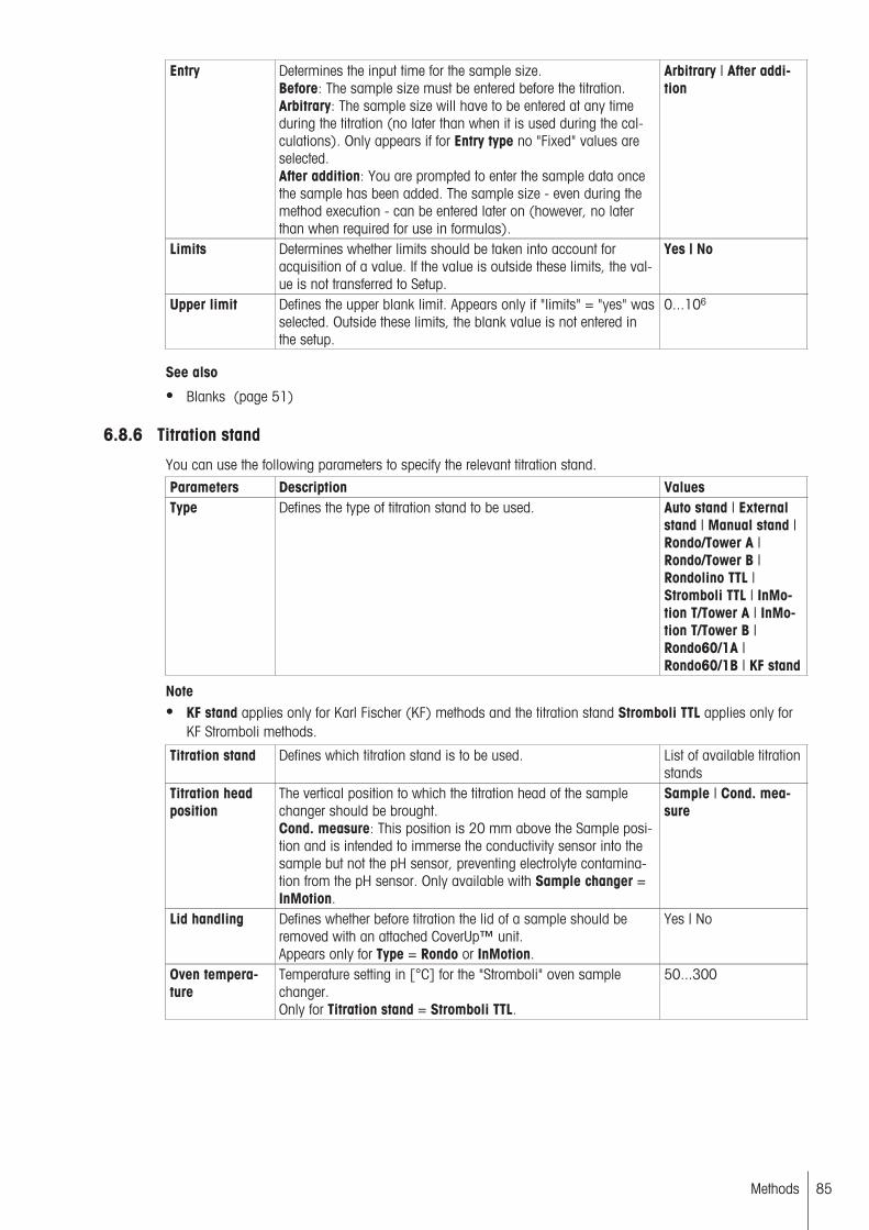
Entry Determines the input time for the sample size.Before: The sample size must be entered before the titration.Arbitrary: The sample size will have to be entered at any timeduring the titration (no later than when it is used during the calculations). Only appears if for Entry type no "Fixed" values areselected.After addition: You are prompted to enter the sample data oncethe sample has been added. The sample size - even during themethod execution - can be entered later on (however, no laterthan when required for use in formulas).
Arbitrary | After addition
Limits Determines whether limits should be taken into account foracquisition of a value. If the value is outside these limits, the value is not transferred to Setup.
Yes | No
Upper limit Defines the upper blank limit. Appears only if "limits" = "yes" wasselected. Outside these limits, the blank value is not entered inthe setup.
0...106
See also
● Blanks (page 51)
6.8.6 Titration stand
You can use the following parameters to specify the relevant titration stand.
Parameters Description ValuesType Defines the type of titration stand to be used. Auto stand | External
stand | Manual stand |Rondo/Tower A |Rondo/Tower B |Rondolino TTL |Stromboli TTL | InMotion T/Tower A | InMotion T/Tower B |Rondo60/1A |Rondo60/1B | KF stand
Note● KF stand applies only for Karl Fischer (KF) methods and the titration stand Stromboli TTL applies only for
KF Stromboli methods.
Titration stand Defines which titration stand is to be used. List of available titrationstands
Titration headposition
The vertical position to which the titration head of the samplechanger should be brought.Cond. measure: This position is 20 mm above the Sample position and is intended to immerse the conductivity sensor into thesample but not the pH sensor, preventing electrolyte contamination from the pH sensor. Only available with Sample changer =InMotion.
Sample | Cond. measure
Lid handling Defines whether before titration the lid of a sample should beremoved with an attached CoverUp™ unit.Appears only for Type = Rondo or InMotion.
Yes | No
Oven temperature
Temperature setting in [°C] for the "Stromboli" oven samplechanger.Only for Titration stand = Stromboli TTL.
50...300
85Methods
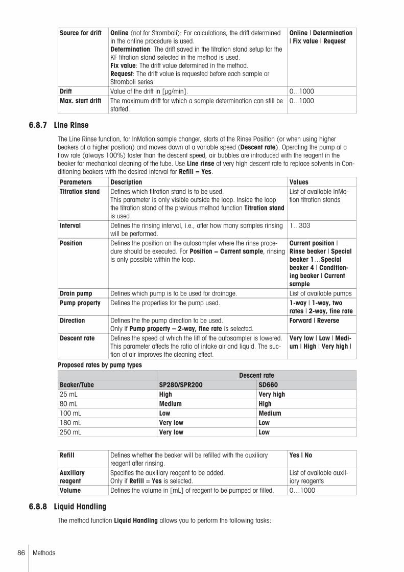
Source for drift Online (not for Stromboli): For calculations, the drift determinedin the online procedure is used.Determination: The drift saved in the titration stand setup for theKF titration stand selected in the method is used.Fix value: The drift value determined in the method.Request: The drift value is requested before each sample orStromboli series.
Online | Determination| Fix value | Request
Drift Value of the drift in [µg/min]. 0...1000Max. start drift The maximum drift for which a sample determination can still be
started.0...1000
6.8.7 Line Rinse
The Line Rinse function, for InMotion sample changer, starts at the Rinse Position (or when using higherbeakers at a higher position) and moves down at a variable speed (Descent rate). Operating the pump at aflow rate (always 100%) faster than the descent speed, air bubbles are introduced with the reagent in thebeaker for mechanical cleaning of the tube. Use Line rinse at very high descent rate to replace solvents in Conditioning beakers with the desired interval for Refill = Yes.
Parameters Description ValuesTitration stand Defines which titration stand is to be used.
This parameter is only visible outside the loop. Inside the loopthe titration stand of the previous method function Titration standis used.
List of available InMotion titration stands
Interval Defines the rinsing interval, i.e., after how many samples rinsingwill be performed.
1...303
Position Defines the position on the autosampler where the rinse procedure should be executed. For Position = Current sample, rinsingis only possible within the loop.
Current position |Rinse beaker | Specialbeaker 1…Specialbeaker 4 | Conditioning beaker | Currentsample
Drain pump Defines which pump is to be used for drainage. List of available pumpsPump property Defines the properties for the pump used. 1-way | 1-way, two
rates | 2-way, fine rateDirection Defines the the pump direction to be used.
Only if Pump property = 2-way, fine rate is selected.Forward | Reverse
Descent rate Defines the speed at which the lift of the autosampler is lowered.This parameter affects the ratio of intake air and liquid. The suction of air improves the cleaning effect.
Very low | Low | Medium | High | Very high |
Proposed rates by pump typesDescent rate
Beaker/Tube SP280/SPR200 SD66025 mL High Very high80 mL Medium High100 mL Low Medium180 mL Very low Low250 mL Very low Low
Refill Defines whether the beaker will be refilled with the auxiliaryreagent after rinsing.
Yes | No
Auxiliaryreagent
Specifies the auxiliary reagent to be added.Only if Refill = Yes is selected.
List of available auxiliary reagents
Volume Defines the volume in [mL] of reagent to be pumped or filled. 0…1000
6.8.8 Liquid Handling
The method function Liquid Handling allows you to perform the following tasks:
86 Methods
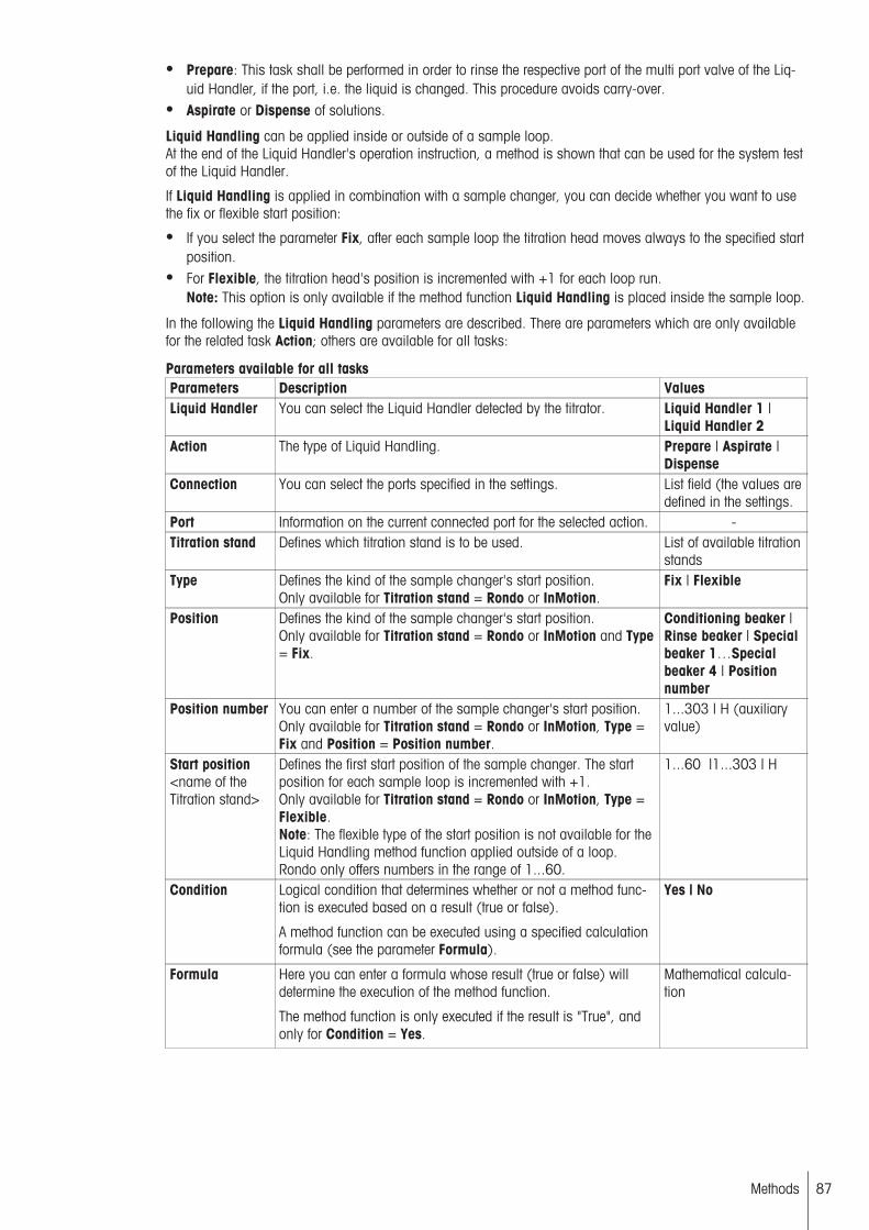
● Prepare: This task shall be performed in order to rinse the respective port of the multi port valve of the Liquid Handler, if the port, i.e. the liquid is changed. This procedure avoids carry-over.
● Aspirate or Dispense of solutions.
Liquid Handling can be applied inside or outside of a sample loop.At the end of the Liquid Handler's operation instruction, a method is shown that can be used for the system testof the Liquid Handler.
If Liquid Handling is applied in combination with a sample changer, you can decide whether you want to usethe fix or flexible start position:
● If you select the parameter Fix, after each sample loop the titration head moves always to the specified startposition.
● For Flexible, the titration head's position is incremented with +1 for each loop run.Note: This option is only available if the method function Liquid Handling is placed inside the sample loop.
In the following the Liquid Handling parameters are described. There are parameters which are only availablefor the related task Action; others are available for all tasks:
Parameters available for all tasksParameters Description ValuesLiquid Handler You can select the Liquid Handler detected by the titrator. Liquid Handler 1 |
Liquid Handler 2Action The type of Liquid Handling. Prepare | Aspirate |
DispenseConnection You can select the ports specified in the settings. List field (the values are
defined in the settings.Port Information on the current connected port for the selected action. -Titration stand Defines which titration stand is to be used. List of available titration
standsType Defines the kind of the sample changer's start position.
Only available for Titration stand = Rondo or InMotion.Fix | Flexible
Position Defines the kind of the sample changer's start position.Only available for Titration stand = Rondo or InMotion and Type= Fix.
Conditioning beaker |Rinse beaker | Specialbeaker 1…Specialbeaker 4 | Positionnumber
Position number You can enter a number of the sample changer's start position.Only available for Titration stand = Rondo or InMotion, Type =Fix and Position = Position number.
1...303 | H (auxiliaryvalue)
Start position<name of theTitration stand>
Defines the first start position of the sample changer. The startposition for each sample loop is incremented with +1.Only available for Titration stand = Rondo or InMotion, Type =Flexible.Note: The flexible type of the start position is not available for theLiquid Handling method function applied outside of a loop.Rondo only offers numbers in the range of 1...60.
1...60 |1...303 | H
Condition Logical condition that determines whether or not a method function is executed based on a result (true or false).
A method function can be executed using a specified calculationformula (see the parameter Formula).
Yes | No
Formula Here you can enter a formula whose result (true or false) willdetermine the execution of the method function.
The method function is only executed if the result is "True", andonly for Condition = Yes.
Mathematical calculation
87Methods

Specific Parameters for PrepareParameters Description ValuesAspiration rate The relative aspiration rate in [%] 1…100
80% =>120 mL/min
Discharge rate The relative dispensing rate in [%] 1…80Rinse port The implementation of a two-stage purification process of the
specified connections with solution.If No is selected, the multiport valve changes to Waste (port 6)and the burette cylinder is emptied.
Yes | No
No. of rinsecycles 1…2
Determines the number of rinse cycles, which will be performed.In general, there are two rinse cycles, one with a large volumeand the other one with low volume.Only available if Rinse port = Yes.
1…5
Volume percycle 1…2
Specifies the rinse volume in [mL] per rinse cycle.Only available if Rinse port = Yes.
0.010…50
Specific Parameters for AspirateParameters Description ValuesAspiration rate The relative aspiration rate in [%] 1…100
80% =>120 mL/min
Aspiration volume
The aspiration volume in [mL]. 0.01…50
Spindle backlash compensation
Specifies spindle backlash compensation in order to compensatespindle tolerances during the operation period of aspirating andpipetting solutions. Also to eliminate air bubbles trapped duringaspiration in tubes or in the burette.Only available for Action = Aspirate.
Yes | No
Wait time With this parameter a waiting period in [s] can be defined afterthe aspiration that enables complete aspiration of viscous liquids.
0…300
Air gap beforeaspiration
Avoids the mixing of the sample solution with the transfer solution in the tube.Only available for Action = Aspirate and for Titration stand =Rondo or InMotion.
Yes | No
Aspiration rate The relative aspiration rate in [%] 1…10080% =>120 mL/min
Volume Specifies the volume in [mL] of the related air gap.Only available for Action = Aspirate and for Air gap before aspiration = Yes.
0.010 ... 1 | H (auxiliary value) | F (formula)
Air gap afteraspiration
Avoids sample loss due to droplet formation.Only available for Action = Aspirate and for Air gap before aspiration = Yes.
Yes | No
Aspiration rate The relative aspiration rate in [%] 1…10080% =>120 mL/min
Volume Specifies the volume in [mL] of the related air gap.Only available for Action = Aspirate and for Air gap before aspiration = Yes.
0.010 ... 1 | H (auxiliary value) | F (formula)
Specific Parameters for DispenseParameters Description ValuesDischarge rate The relative dispensing rate in [%] 1…80Discharge volume
The dispensing volume in [mL]. 0.01…500
88 Methods

Refill This parameter is used if volumes are required which exceeds themaximum burette volume (50 mL). If activated, you can specifythe Connection and the Aspiration rate for the automatic refillingof the burette.For multiple aspiration, be aware that volume shall be a multipleof 25 µL.
Yes | No
Note● Both, Aspiration rate and Discharge rate depend on the viscosity of the solution. Low rate values are
required for highly viscous liquids and high rate values for liquids with a low viscosity (for more informationabout the viscosity of some liquids at room temperature refer to:• http://hyperphysics.phy-astr.gsu.edu/Hbase/tables/viscosity.html• 5,000 centipoise is the maximum value. Aspiration of high viscous samples require a waiting time after
the aspiration step is completed.
See also
● Evaluate and calculate (page 145)
6.8.9 Mix time
You can use the "Mix time" method function to define the stir time in [s] for Karl Fischer titration. This value isobtained from experience and can be entered individually for each sample.The stir speed, however, is entered in the method function "Titration" using the "Stir" parameter. This applies forthe whole method.
Parameters Description ValuesDuration Duration in [s]. 1...104
6.8.10 Rinse
You can use this method function to rinse a sensor. You can define the following parameters:
Parameters Description ValuesTitration stand Selects a titration stand defined in the setup. Appears only if the
method function Rinse is used outside of a sample loop.Select the titrationstands from the listspecified in Setup.
Auxiliaryreagent
The auxiliary reagent to be added. List of available auxiliary reagents
Rinse cycles The number of rinse cycles to be run. 1…100Vol. per cycle The rinse volume in [mL] per cycle. 0…1000Position Defines the position on the sample changer where the rinse pro
cedure should be executed. The rinsing beaker can only beselected for a connected Rondo. Rinsing in the Current sampleposition is only possible within the loop.
Current position |Rinse beaker | Currentsample
Drain Defines whether the contents of the rinse vessel should bedrained before starting the rinse procedure. This is always automatically set to "Yes" if the Position has been set to Rinsebeaker or if more than one rinse cycle is executed.
Yes | No
Drain pump Defines which pump is to be used for drainage. List of available pumpsCondition Logical condition that determines whether or not a method func
tion is executed based on a result (true or false).
A method function can be executed using a specified calculationformula (see the parameter Formula).
Yes | No
Formula Here you can enter a formula whose result (true or false) willdetermine the execution of the method function.
The method function is only executed if the result is "True", andonly for Condition = Yes.
Mathematical calculation
89Methods

See also
● Evaluate and calculate (page 145)
6.8.11 Conditioning
Use this method function to prepare a sensor for the next analysis. This method function becomes active whena sample changer is selected.
Parameters Description ValuesTitration stand Activates a sample changer defined in the setup. Appears only if
the method function Conditioning is used outside of a sampleloop.
List of titration stands
Interval Defines the conditioning interval, i.e., after how many samplesconditioning will be performed.Appears only when inside a loop.
1...60 (Rondo) |1…303 (InMotion)
Position Defines the position of the conditioning beaker. Variable positionuses the defined interval to define the position(s). Variable position can only be selected if Titration stand = InMotion selectedand method function is used within a loop.
Variable position |Special beaker 1…4 |Conditioning beaker
Cond. beakerspacing
Defines where the conditioning beakers are positioned on therack for variable conditioning beaker positions: value = numberof sample beakers between two conditioning beakers.Note that the beaker series must start with a conditioning beaker.The start position in the series or in analysis start must be set tothe first conditioning beaker. E.g. Cond. beaker spacing = 3defines following beaker series: C S S S C S S S C etc. where C isa conditioning beaker and S is a sample beaker.
1…303
Time Defines the conditioning period in [sec]. 1…104
Speed Defines the stirring speed in [%]. 0…100Lid handling Defines whether before titration the lid of a sample should be
removed with an attached CoverUp™ unit.Appears only for Type = InMotion.
Yes | No
Condition Logical condition that determines whether or not a method function is executed based on a result (true or false).
A method function can be executed using a specified calculationformula (see the parameter Formula).
Yes | No
Formula Here you can enter a formula whose result (true or false) willdetermine the execution of the method function.
The method function is only executed if the result is "True", andonly for Condition = Yes.
Mathematical calculation
See also
● Evaluate and calculate (page 145)
6.8.12 Pump
You can use this method function to drain a reagent into a sample vessel.
Parameters Description ValuesAuxiliaryreagent
The auxiliary reagent to be added. List of available auxiliary reagents
Volume Volume in [mL]. 0.0001…1000 | Auxiliary value | Formula
Pump property Defines the properties for the pump used. 1-way | 1-way, tworates | 2-way, fine rate
Rate Allows to reduce the pump rate.Only if the pump supports this and if the pump is connected toan InMotion.
10…100 (2-way, finerate) | 50/100 (1-way,two rates)
90 Methods

Direction Defines the pump direction for a 2-way pump Forward | ReverseCondition Logical condition that determines whether or not a method func
tion is executed based on a result (true or false).
A method function can be executed using a specified calculationformula (see the parameter Formula).
Yes | No
Formula Here you can enter a formula whose result (true or false) willdetermine the execution of the method function.
The method function is only executed if the result is "True", andonly for Condition = Yes.
Mathematical calculation
See also
● Evaluate and calculate (page 145)
6.8.13 Park
Activates the park function for a sample changer. So that for instance the sensor can be deposited into a selected sample vessel at the end of a sample series.
Parameters Description ValuesTitration stand Defines which titration stand is to be used. List of available titration
standsPosition Defines the position in which to park the titration head.
For Current position, the head is parked in the last active position (for example: Sample).For Current position + 1, the head is parked in the beaker afterthe last active position.
Conditioning beaker |Rinse beaker | Specialbeaker 1…Specialbeaker 4 | Currentposition | Current position + 1
Condition Logical condition that determines whether or not a method function is executed based on a result (true or false).
A method function can be executed using a specified calculationformula (see the parameter Formula).
Yes | No
Formula Here you can enter a formula whose result (true or false) willdetermine the execution of the method function.
The method function is only executed if the result is "True", andonly for Condition = Yes.
Mathematical calculation
See also
● Evaluate and calculate (page 145)
6.8.14 Stir
Activates or deactivates (speed ="0") the stirrer of the current titration stand.
Parameters Description ValuesSpeed Defines the stirring speed in [%]. 0…100Duration The stirring time, in [sec]. (Can also be defined by an auxiliary
value or a formula.)After the stirring time has elapsed, the titrator will continue to thenext method function without switching off the stirrer. The methodfunctions End of sample and Titration stand switch off the stirrer.The stirrer output is defined by the prior method function Titrationstand.
0…105 | Auxiliary value/Formula
Condition Logical condition that determines whether or not a method function is executed based on a result (true or false).
A method function can be executed using a specified calculationformula (see the parameter Formula).
Yes | No
91Methods

Formula Here you can enter a formula whose result (true or false) willdetermine the execution of the method function.
The method function is only executed if the result is "True", andonly for Condition = Yes.
Mathematical calculation
See also
● Evaluate and calculate (page 145)
6.8.15 Dispense (normal)
You can use this method function to dispense a precisely defined quantity of titrant.
The smallest increment (dV(min)) is 1/20000 of the burette volume, i.e. for the following burettes:
1 mL burette: dV(min) = 0.05 µL5 mL burette: dV(min) = 0.25 µL10 mL burette: dV(min) = 0.50 µL20 mL burette: dV(min) = 1 µL
Parameters Description ValuesTitrant Select a titrant from the list of the defined titrants. Titrant listVolume Volume in [mL]. 0.0001…1000 | Auxil
iary value | FormulaDosing rate Defines the dosing rate (not including the filling time), in
[mL/min]. You can also select a burette type-dependent maximum number.
0.01…60
Condition Logical condition that determines whether or not a method function is executed based on a result (true or false).
A method function can be executed using a specified calculationformula (see the parameter Formula).
Yes | No
Formula Here you can enter a formula whose result (true or false) willdetermine the execution of the method function.
The method function is only executed if the result is "True", andonly for Condition = Yes.
Mathematical calculation
See also
● Evaluate and calculate (page 145)
6.8.16 Sync
This function is only supported by the titrator model T90.
Five synchronization codes are used for synchronizing methods running simultaneously in both workspaces Aand B. Each of the codes is accessible for any running method using this method function. Methods can bedesigned so that one method syncs another and vice versa.
When the parameter Action is set to Wait within a method function Sync, the method will be waiting at thispoint. The method will be continued as soon as the parameter Action set to Send from a second runningmethod is reached for the same number selected in Code.
Always begin an analysis by starting the method that first contains a parameter Action = Send. This fixes thestatus of the codes and enables the correct order of the sequence.
If using a series sequence containing two series, order the series with method containing the Action = Sendfirst in the sequence series.
Define the following parameters:
Parameters Description ValuesAction Defines if a code is to be sent or received. Send | WaitCode Individually identifies the code to be sent or received. 1 | 2 | 3 | 4 | 5
92 Methods
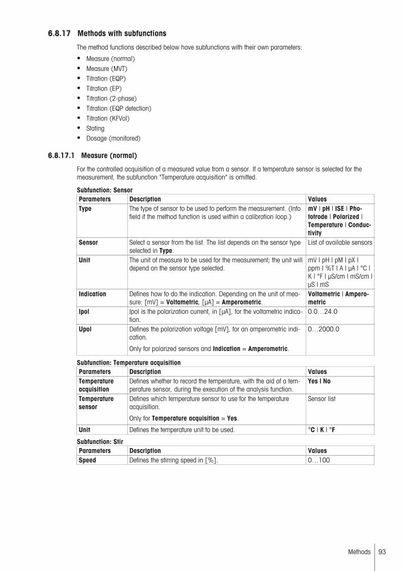
6.8.17 Methods with subfunctions
The method functions described below have subfunctions with their own parameters:
● Measure (normal)● Measure (MVT)● Titration (EQP)● Titration (EP)● Titration (2-phase)● Titration (EQP detection)● Titration (KFVol)● Stating● Dosage (monitored)
6.8.17.1 Measure (normal)
For the controlled acquisition of a measured value from a sensor. If a temperature sensor is selected for themeasurement, the subfunction "Temperature acquisition" is omitted.
Subfunction: SensorParameters Description ValuesType The type of sensor to be used to perform the measurement. (Info
field if the method function is used within a calibration loop.)mV | pH | ISE | Phototrode | Polarized |Temperature | Conductivity
Sensor Select a sensor from the list. The list depends on the sensor typeselected in Type.
List of available sensors
Unit The unit of measure to be used for the measurement; the unit willdepend on the sensor type selected.
mV | pH | pM | pX |ppm | %T | A | µA | °C |K | °F | µS/cm | mS/cm |µS | mS
Indication Defines how to do the indication. Depending on the unit of measure: [mV] = Voltametric, [µA] = Amperometric.
Voltametric | Amperometric
Ipol Ipol is the polarization current, in [µA], for the voltametric indication.
0.0…24.0
Upol Defines the polarization voltage [mV], for an amperometric indication.
Only for polarized sensors and Indication = Amperometric.
0…2000.0
Subfunction: Temperature acquisitionParameters Description ValuesTemperatureacquisition
Defines whether to record the temperature, with the aid of a temperature sensor, during the execution of the analysis function.
Yes | No
Temperaturesensor
Defines which temperature sensor to use for the temperatureacquisition.
Only for Temperature acquisition = Yes.
Sensor list
Unit Defines the temperature unit to be used. °C | K | °F
Subfunction: StirParameters Description ValuesSpeed Defines the stirring speed in [%]. 0…100
93Methods

Subfunction: Acquisition of measured valuesParameters Description ValuesAcquisition Defines how the measured value is acquired.
Equilibrium-controlled: The measured value is acquired as soonas it stabilizes.- Fix: The measured value is acquired after a defined waitingperiod.- Set value: The measured value is acquired as soon as it hasexceeded, or fallen short of, a specific set value. (The Set Valueoption is not available if the method function is used within aSample (Calib) loop.)
Equilibrium Controlled |Fixed | Set Value
Parameters for sensor types: mV, pH, ISE, Phototrode, Polarized, ConductivityParameters Description ValuesdE Defines the measured value interval. As soon as the change in
the measured value over the time period dt is less than dE, themeasured value will be acquired. This occurs within the definedtime interval of t(min) to t(max).dE is specified in the unchanged unit of the sensor per second:- mV for the mV sensor type, pH, ISE, phototrode and polarizedvoltametric- µA for polarized amperometric- mS | µS for conductivity sensor (only for "Acquisition " = "Equilibrium controlled".)
0.02…15
dt Defines the time component, in [sec] for dE/dt. (For "acquisition"= "equilibrium-controlled" only.)
1…150
t(min) Earliest possible time for the measured value acquisition, in[sec]. (For "acquisition" = "equilibrium-controlled" only.)
1…150
t(max) Latest possible time for the measured value acquisition, in [sec].(For "acquisition" = "equilibrium-controlled" only.)
1…105
Time Waiting time, in [sec], before acquisition of a measured valuewhen "acquisition" = "Fixed".
1…105
Mode Mode for the measured value acquisition of the "set value".E > set value acquires the measured value as soon as the setvalue has been exceeded.E < set value acquires the measured value as soon as the measured value falls below the set value. Not available within a calibration loop.Only for Acquisition = Set value.
E > set value | E < setvalue
Set value Set value in the sensor unit. Measured values will be acquiredafter they exceed or fall below this value, depending on the modesetting. (For "acquisition" = "set value" only.) Not available within a calibration loop.
(See "Value Ranges ofSensor Measuring Unitsand Control Band(page 29)")
t(max) Latest time for the measured value acquisition, in [sec]. (For"acquisition" = "set value" only.) Not available within a calibration loop.
1…105
Mean value The system finds a mean value for the saved measured value,using a maximum of 10 measured values.
Yes | No
No. of measuredvalues
When you want to calculate a mean value, you can define thenumber of measured values used to find that mean value here.
1…10
dt Defines the time interval, in [sec], for the measured value acquisition of the measured values to be averaged. (Appears only if"mean value" = "yes" is selected.)
1…60
94 Methods
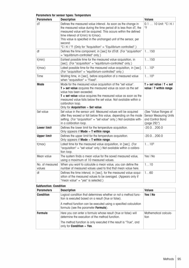
Parameters for sensor types: TemperatureParameters Description ValuesdT Defines the measured value interval. As soon as the change in
the measured value during the time period dt is less than dT, themeasured value will be acquired. This occurs within the definedtime interval of t(min) to t(max).This value is specified in the unchanged unit of the sensor, persecond:°C | K | °F (Only for "Acquisition" = "Equilibrium controlled".)
0.1 … 10 Unit: °C | K |°F
dt Defines the time component, in [sec] for dT/dt. (For "acquisition"= "equilibrium-controlled" only.)
1…150
t(min) Earliest possible time for the measured value acquisition, in[sec]. (For "acquisition" = "equilibrium-controlled" only.)
1…150
t(max) Latest possible time for the measured value acquisition, in [sec].(For "acquisition" = "equilibrium-controlled" only.)
1…105
Time Waiting time, in [sec], before acquisition of a measured valuewhen "acquisition" = "Fixed".
1…105
Mode Mode for the measured value acquisition of the "set value".T > set value acquires the measured value as soon as the setvalue has been exceeded.T < set value value acquires the measured value as soon as themeasured value falls below the set value. Not available within acalibration loop.Only for Acquisition = Set value.
T > set value | T < setvalue | T within range
Set value Set value in the sensor unit. Measured values will be acquiredafter they exceed or fall below this value, depending on the modesetting. (For "acquisition" = "set value" only.) Not available within a calibration loop.
(See "Value Ranges ofSensor Measuring Unitsand Control Band(page 29)")
Lower limit Defines the lower limit for the temperature acquisition.Only appears if Mode = T within range.
-20.0…200.0
Upper limit Defines the upper limit for the temperature acquisition.Only appears if Mode = T within range.
-20.0…200.0
t(max) Latest time for the measured value acquisition, in [sec]. (For"acquisition" = "set value" only.) Not available within a calibration loop.
1…105
Mean value The system finds a mean value for the saved measured value,using a maximum of 10 measured values.
Yes | No
No. of measuredvalues
When you want to calculate a mean value, you can define thenumber of measured values used to find that mean value here.
1…10
dt Defines the time interval, in [sec], for the measured value acquisition of the measured values to be averaged. (Appears only if"mean value" = "yes" is selected.)
1…60
Subfunction: ConditionParameters Description ValuesCondition Logical condition that determines whether or not a method func
tion is executed based on a result (true or false).
A method function can be executed using a specified calculationformula (see the parameter Formula).
Yes | No
Formula Here you can enter a formula whose result (true or false) willdetermine the execution of the method function.
The method function is only executed if the result is "True", andonly for Condition = Yes.
Mathematical calculation
95Methods
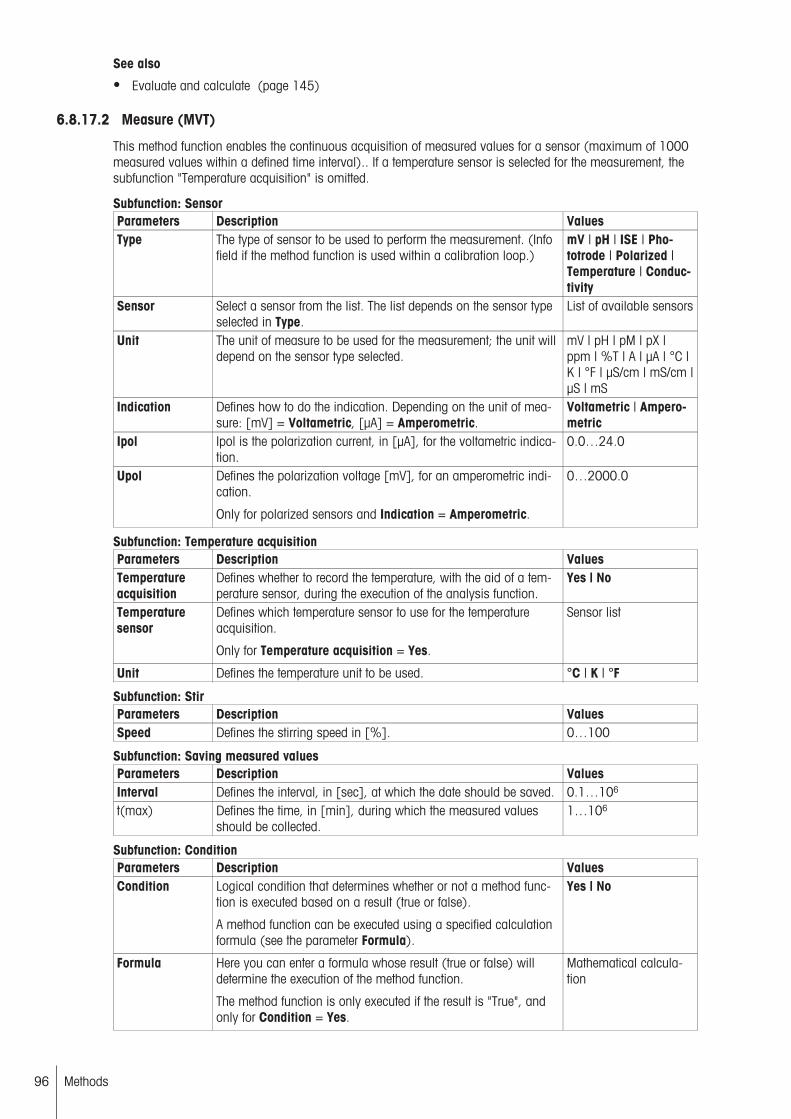
See also
● Evaluate and calculate (page 145)
6.8.17.2 Measure (MVT)
This method function enables the continuous acquisition of measured values for a sensor (maximum of 1000measured values within a defined time interval).. If a temperature sensor is selected for the measurement, thesubfunction "Temperature acquisition" is omitted.
Subfunction: SensorParameters Description ValuesType The type of sensor to be used to perform the measurement. (Info
field if the method function is used within a calibration loop.)mV | pH | ISE | Phototrode | Polarized |Temperature | Conductivity
Sensor Select a sensor from the list. The list depends on the sensor typeselected in Type.
List of available sensors
Unit The unit of measure to be used for the measurement; the unit willdepend on the sensor type selected.
mV | pH | pM | pX |ppm | %T | A | µA | °C |K | °F | µS/cm | mS/cm |µS | mS
Indication Defines how to do the indication. Depending on the unit of measure: [mV] = Voltametric, [µA] = Amperometric.
Voltametric | Amperometric
Ipol Ipol is the polarization current, in [µA], for the voltametric indication.
0.0…24.0
Upol Defines the polarization voltage [mV], for an amperometric indication.
Only for polarized sensors and Indication = Amperometric.
0…2000.0
Subfunction: Temperature acquisitionParameters Description ValuesTemperatureacquisition
Defines whether to record the temperature, with the aid of a temperature sensor, during the execution of the analysis function.
Yes | No
Temperaturesensor
Defines which temperature sensor to use for the temperatureacquisition.
Only for Temperature acquisition = Yes.
Sensor list
Unit Defines the temperature unit to be used. °C | K | °F
Subfunction: StirParameters Description ValuesSpeed Defines the stirring speed in [%]. 0…100
Subfunction: Saving measured valuesParameters Description ValuesInterval Defines the interval, in [sec], at which the date should be saved. 0.1…106
t(max) Defines the time, in [min], during which the measured valuesshould be collected.
1…106
Subfunction: ConditionParameters Description ValuesCondition Logical condition that determines whether or not a method func
tion is executed based on a result (true or false).
A method function can be executed using a specified calculationformula (see the parameter Formula).
Yes | No
Formula Here you can enter a formula whose result (true or false) willdetermine the execution of the method function.
The method function is only executed if the result is "True", andonly for Condition = Yes.
Mathematical calculation
96 Methods

See also
● Evaluate and calculate (page 145)
6.8.17.3 Titration (EQP)
Carries out an equivalence-point titration. You can define the relevant parameters for the following subfunctions:
Subfunction: TitrantParameters Description ValuesTitrant Select a titrant from the list of the defined titrants. Titrant list
Subfunction: SensorType The type of sensor to be used to perform the measurement. (Info
field if the method function is used within a calibration loop.)mV | pH | ISE | Phototrode | Polarized |Temperature | Conductivity
Sensor Select a sensor from the list. The list depends on the sensor typeselected in Type.
List of available sensors
Unit The unit of measure to be used for the measurement; the unit willdepend on the sensor type selected.
mV | pH | pM | pX |ppm | %T | A | µA | °C |K | °F | µS/cm | mS/cm |µS | mS
Indication Defines how to do the indication. Depending on the unit of measure: [mV] = Voltametric, [µA] = Amperometric.
Voltametric | Amperometric
Ipol Ipol is the polarization current, in [µA], for the voltametric indication.
0.0…24.0
Frequency Polarization frequency in [Hz]. The standard frequency is 4 Hz;other values should only be used for special applications.
Only for Type = Polarized, and Unit = mV.
4 | 2 | 1 | 0.5
Upol Defines the polarization voltage [mV], for an amperometric indication.
Only for polarized sensors and Indication = Amperometric.
0…2000.0
Subfunction: Temperature acquisitionParameters Description ValuesTemperatureacquisition
Defines whether to record the temperature, with the aid of a temperature sensor, during the execution of the analysis function.
Yes | No
Temperaturesensor
Defines which temperature sensor to use for the temperatureacquisition.
Only for Temperature acquisition = Yes.
Sensor list
Unit Defines the temperature unit to be used. °C | K | °F
Subfunction: StirSpeed Defines the stirring speed in [%]. 0…100
Subfunction: PredispensingParameters Description ValuesMode Specifies the type of addition:
Volume: predispenses a specific volume.Potential: system predispenses a substance until a certainpotential is reached.Factor: A multiple of the sample size is predispensed.None: does not predispense.
Volume | Potential |Factor | None
Volume The volume to be predispensed in [mL].
Only for Mode = Volume.
0.0001…1000 | Auxiliary value | Formula
Potential The potential at which predispensing is stopped.
Only for Mode = Potential.
Depends on the sensor
97Methods

Factor The system calculates the predispensing volume by multiplyingthe factor by the sample size.
For Mode = Factor only.
0…105 | Auxiliary value | Formula
Wait time Defines a waiting time, in [sec].After predispensing or, if Mode = None, before the start of titration.
0…32000
Subfunction: ControlParameters Description ValuesControl Here you can select from among three predefined control modes,
or you can select User to define all the parameters as freelyeditable.If you change from Normal, Fast, Cautious to User, the systemwill copy over the predefined parameter settings and they willthen be freely editable.
Normal | Fast | Cautious | User
Mode Select an application depending on the sensor type. The selectedapplication will then provide its own specific parameter set.
Not available for Control = User.
Application list
Show parameters
Here you can select whether to display the preset parameters ofthe control modes Normal, Fast or Cautious as non-editable infofields.
Not for Control = User.
Yes | No
Titrant addition Defines whether to always dispense the same volume defined bydV (Incremental) or to adjust the volume to be titrated per stepas the titration progresses (Dynamic).
Only for Control = User.
Dynamic | Incremental
dE(set value) Defines the potential difference targeted per titrant addition.
Only for Control = User and Titrant addition = Dynamic.
[mV/µA] 0.1…100[mS/µS] 0.01…100
dT(set value) Defines the temperature difference in the unit of the temperaturesensor that is targeted for a temperature sensor per titrant addition.
For Control = User and Titrant addition = Dynamic only.
0.1…100
dV(min) Defines the minimum amount for a titrant addition, in [mL].
For Control = User and Titrant addition = Dynamic only.
0.0001…1
dV(max) Defines the maximum amount for a titrant addition, in [mL].
For Control = User and Titrant addition = Dynamic only.
0.0001…10
dV Defines the volume increment, in [mL], for the incremental titrantaddition.
For Control = User and Titrant addition = Incremental only.
0.0001…10
Meas. val.acquisition
Type of measuring value acquisition:Equilibrium controlled: The system acquires the measured valueand makes the next titrant addition as soon as a stable measured value is established.Fixed time: The measured values acquisition and the titrantaddition occur according to fixed time intervals.
Only for Control = User.
Equilibrium controlled| Fixed time
dE As soon as the change in the measured value during the timeperiod dt is less than dE, the measured value will be acquired.Acquisition takes place no earlier than after t(min) and no laterthan after t(max). Then the next titrant addition is conducted.
For Control = User and Meas. val. acquisition = Equilibriumcontrolled only.
[mV/µA] 0.1 … 15[mS/µS] 0.01 … 15
98 Methods

dT As soon as the change in the measured value during the timeperiod dt is less than dT, the measured value will be acquired.Acquisition takes place no earlier than after t(min) and no laterthan after t(max). Then the next titrant addition is conducted.
For Control = User and Meas. val. acquisition = Equilibriumcontrolled for a temperature sensor only.
0.1…15
dt Defines the time interval, in [sec], for calculating dE/dt (or dT/dtfor a temperature sensor).
For Control = User and Meas. val. acquisition = Equilibriumcontrolled only.
0.1…15
t(min) Earliest possible time for the measured value acquisition, in[sec].
Only for Control = User and Meas. val. acquisition = Equilibrium controlled.
0.5…150
t(max) Latest possible time for the measured value acquisition, in [sec].
Only for Control = User and Meas. val. acquisition = Equilibrium controlled.
1…105
dt Defines the time interval, in [sec], for Fixed time.
For Control = User and Meas. val. acquisition = Fixed timeonly.
0.5…6000
Subfunction: Evaluation and recognitionParameters Description ValuesProcedure Defines which evaluation procedure to use. Standard |
Asymmetric |Minimum | Maximum |Segmented
Threshold Defines the threshold (absolute amount) that must be exceededfor the recognition of an EQP. Procedure = Minimum and Maximum: This threshold valuerefers to the original curve [UoM]Procedure = Standard and Asymmetric: It refers to the 1st derivative of the original curve [UoM*/mL].Procedure = Segmented: It refers to the 2nd derivative of theoriginal curve [UoM/mL].
Standard,Asymmetric and Segmented: 0 … 106
Minimum and Maximum: Depends on thesensor
* UoM: Unit of Measurement
Tendency Defines the tendency for which the EQP is to be detected.
For Procedure = Standard, Asymmetric and Segmented.
Positive | Negative |None
Ranges You can define up to three recognition ranges. Outside theseranges, the system will recognize neither EQP's nor EQP candidates.Depending on what is defined here, upper and lower limits aredefined for each recognition range and also whether additionalEQP criteria are to be used for each recognition range.
1 | 2 | 3 | 0
Lower limit 1-3 Defines the lower limit for the recognition range. The unit of measure will depend on the sensor used.
Does not appear if Ranges = 0.
Depends on the sensor
Upper limit 1-3 Defines the upper limit for the recognition range. The unit of measure will depend on the sensor used.
Does not appear if Ranges = 0.
Depends on the sensor
99Methods

Add. EQP criteria
Defines whether to take additional EQP criteria into consideration.The available selection will depend on the evaluation procedurechosen. They can be defined individually for each recognitionrange or for the overall recognition range (Ranges = 0).Last EQP: The system only considers the quantity of EQPsdefined.Steepest jump: The system only considers the number of steepest jumps defined.Lowest value: The system only considers the number of lowestvalues defined.Highest value: The system only considers the number of highestvalues defined.
Last EQP | Steepestjump | Lowest value |Highest value | No
Last jumps The quantity of last jumps to be taken into consideration.
Only for Add. EQP criteria = Last EQP.
1…9
Steepest jumps The quantity of steepest jumps to be taken into consideration.
Only for Add. EQP criteria = Steepest jump.
1…9
Lowest values The quantity of lowest values to be taken into consideration.
Only for Add. EQP criteria = Lowest value.
1…9
Highest values The quantity of highest values to be taken into consideration.
Only for Add. EQP criteria = Highest value.
1…9
Buffer capacity Determination of buffer capacity with VEQ/2. Only possible forsensor unit "pH" and volume-based sample entry (Sample >Entry type = Volume or Fixed volume).
Yes | No
Subfunction: TerminationParameters Description ValuesAt Vmax Defines the maximum volume, in [mL], at which the titration
must be terminated if it has not been terminated already.0.1…1000 | Auxiliaryvalue | Formula
At potential Defines whether to terminate the titration after reaching a definedpotential (with the correct tendency!).
Yes | No
Potential The potential at which to terminate the titration. The unit of measure will depend on the sensor used.
Only for At potential = Yes.
-100...100 | Auxiliaryvalue | Formula(Depends on the sensor)
Termination tendency
Defines for which tendency the titration should be terminated.
Only for At potential = Yes.
Positive | Negative |None
At slope Defines whether to terminate the titration after reaching a definedslope. This absolute value must be exceeded by one measuredvalue and then be greater than two measured values to result intermination.
Yes | No
Slope The slope, in [unit of measure/mL], at which to terminate thetitration.
Only for At slope = Yes.
0...105 | Auxiliary value | Formula
After number ofrecognized EQPs
Specifies whether the titration should be terminated after therecognition of a specific quantity of EQP candidates. The EQPcandidates must fulfill the following conditions:- It lies within the recognition range defined in Ranges.- It is above the threshold defined in Threshold- It show the correct tendency as defined in Tendency. If no additional EQP criteria should be considered, then EQP candidate =EQP applies.
Yes | No
Number of EQPs Defines the quantity of EQP candidates after the recognition ofwhich the system should terminate the titration.
Only for After number of recognized EQPs = Yes.
1…30 | Auxiliary value | Formula
100 Methods
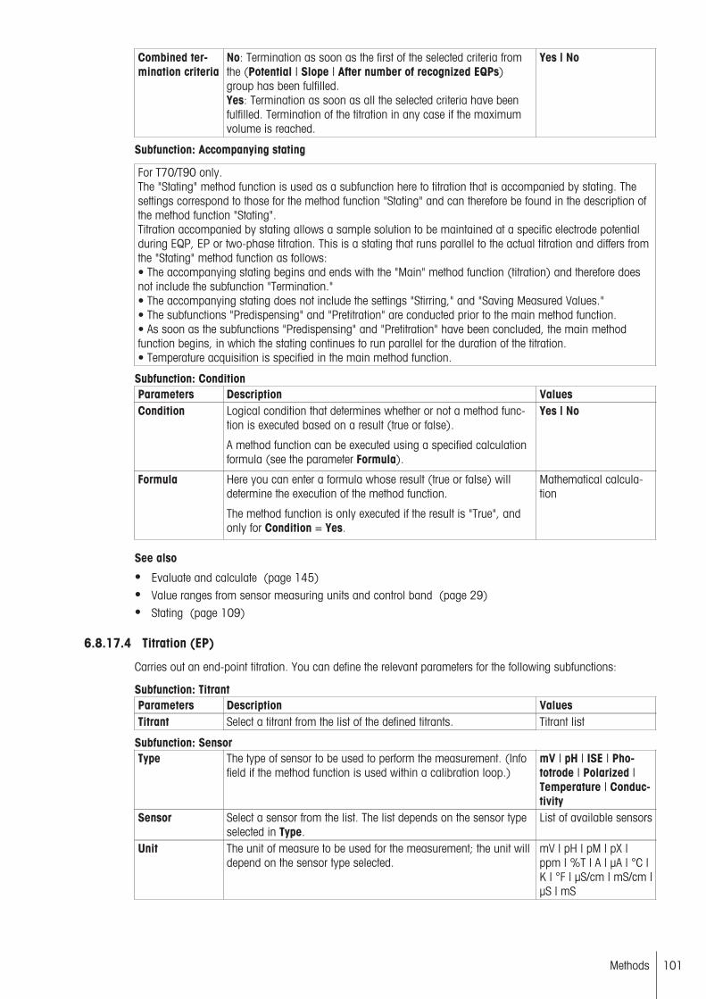
Combined termination criteria
No: Termination as soon as the first of the selected criteria fromthe (Potential | Slope | After number of recognized EQPs)group has been fulfilled.Yes: Termination as soon as all the selected criteria have beenfulfilled. Termination of the titration in any case if the maximumvolume is reached.
Yes | No
Subfunction: Accompanying stating
For T70/T90 only.The "Stating" method function is used as a subfunction here to titration that is accompanied by stating. Thesettings correspond to those for the method function "Stating" and can therefore be found in the description ofthe method function "Stating".Titration accompanied by stating allows a sample solution to be maintained at a specific electrode potentialduring EQP, EP or two-phase titration. This is a stating that runs parallel to the actual titration and differs fromthe "Stating" method function as follows:• The accompanying stating begins and ends with the "Main" method function (titration) and therefore doesnot include the subfunction "Termination."• The accompanying stating does not include the settings "Stirring," and "Saving Measured Values."• The subfunctions "Predispensing" and "Pretitration" are conducted prior to the main method function.• As soon as the subfunctions "Predispensing" and "Pretitration" have been concluded, the main methodfunction begins, in which the stating continues to run parallel for the duration of the titration.• Temperature acquisition is specified in the main method function.
Subfunction: ConditionParameters Description ValuesCondition Logical condition that determines whether or not a method func
tion is executed based on a result (true or false).
A method function can be executed using a specified calculationformula (see the parameter Formula).
Yes | No
Formula Here you can enter a formula whose result (true or false) willdetermine the execution of the method function.
The method function is only executed if the result is "True", andonly for Condition = Yes.
Mathematical calculation
See also
● Evaluate and calculate (page 145)● Value ranges from sensor measuring units and control band (page 29)● Stating (page 109)
6.8.17.4 Titration (EP)
Carries out an end-point titration. You can define the relevant parameters for the following subfunctions:
Subfunction: TitrantParameters Description ValuesTitrant Select a titrant from the list of the defined titrants. Titrant list
Subfunction: SensorType The type of sensor to be used to perform the measurement. (Info
field if the method function is used within a calibration loop.)mV | pH | ISE | Phototrode | Polarized |Temperature | Conductivity
Sensor Select a sensor from the list. The list depends on the sensor typeselected in Type.
List of available sensors
Unit The unit of measure to be used for the measurement; the unit willdepend on the sensor type selected.
mV | pH | pM | pX |ppm | %T | A | µA | °C |K | °F | µS/cm | mS/cm |µS | mS
101Methods

Indication Defines how to do the indication. Depending on the unit of measure: [mV] = Voltametric, [µA] = Amperometric.
Voltametric | Amperometric
Ipol Ipol is the polarization current, in [µA], for the voltametric indication.
0.0…24.0
Upol Defines the polarization voltage [mV], for an amperometric indication.
Only for polarized sensors and Indication = Amperometric.
0…2000.0
Subfunction: Temperature acquisitionParameters Description ValuesTemperatureacquisition
Defines whether to record the temperature, with the aid of a temperature sensor, during the execution of the analysis function.
Yes | No
Temperaturesensor
Defines which temperature sensor to use for the temperatureacquisition.
Only for Temperature acquisition = Yes.
Sensor list
Unit Defines the temperature unit to be used. °C | K | °F
Subfunction: StirSpeed Defines the stirring speed in [%]. 0…100
Subfunction: PredispensingParameters Description ValuesMode Specifies the type of addition:
Volume: predispenses a specific volume.Potential: system predispenses a substance until a certainpotential is reached.Factor: A multiple of the sample size is predispensed.None: does not predispense.
Volume | Potential |Factor | None
Volume The volume to be predispensed in [mL].
Only for Mode = Volume.
0.0001…1000 | Auxiliary value | Formula
Potential The potential at which predispensing is stopped.
Only for Mode = Potential.
Depends on the sensor
Factor The system calculates the predispensing volume by multiplyingthe factor by the sample size.
For Mode = Factor only.
0…105 | Auxiliary value | Formula
Wait time Defines a waiting time, in [sec].After predispensing or, if Mode = None, before the start of titration.
0…32000
Subfunction: ControlParameters Description ValuesEnd point type Absolute: Titration is ended when the absolute measured value is
reached.Relative: The system will take into consideration the differencebetween the desired end point and the measured value at thestart of the titration.
Absolute | Relative
Tendency Defines the direction of change for the measured value during thetitrant addition. If the starting potential, end point and tendencyare inconsistent at the start of the analysis, the system will terminate the analysis immediately.
For End point type = Absolute only.
Positive | Negative |None
End point value The defined titration end point. The unit will depend on the sensorused.
Depends on the sensor | Formula | Auxiliary value
102 Methods

Control band This number defines the width of the control band. Outside thecontrol band, the system will titrate with the maximum dispensing rate. The smaller the control band, the faster the titrator willreact to a deviation from the potential of the defined end point.When the measurement curve reaches the control band, the titrator will slow down the titrant addition to approach the end pointin a cautious manner. The unit will depend on the sensor used.
Depends on the sensor | Auxiliary value
Dosing rate(max)
The maximum dosing rate in [mL/min]. 0.001…60
Dosing rate(min)
The minimum dosing rate in [µL/min]. 1…104
Subfunction: TerminationParameters Description ValuesAt EP Defines whether to terminate the titration after reaching the end
point.If No is selected, after reaching the end point the system will continue acquiring measured values without adding titrant until themaximum time period is reached.
Yes | No
Terminationdelay
The termination delay which defines the time period, in [sec],between reaching the end point and terminating the titration. Ifduring the termination delay the measured value drops below theend point, the system will add further increments and restart thetermination delay.
Only if At EP = Yes is selected.)
0…108 | Auxiliary value
At Vmax Defines the maximum volume, in [mL], at which the titrationmust be terminated if it has not been terminated already.
0.1…1000 | Auxiliaryvalue | Formula
Max. time Defines the maximum time of the titration, in [sec]. 0…108 | ∞ | Auxiliaryvalue
Subfunction: Accompanying stating
For T70/T90 only.The "Stating" method function is used as a subfunction here to titration that is accompanied by stating. Thesettings correspond to those for the method function "Stating" and can therefore be found in the description ofthe method function "Stating".Titration accompanied by stating allows a sample solution to be maintained at a specific electrode potentialduring EQP, EP or two-phase titration. This is a stating that runs parallel to the actual titration and differs fromthe "Stating" method function as follows:• The accompanying stating begins and ends with the "Main" method function (titration) and therefore doesnot include the subfunction "Termination."• The accompanying stating does not include the settings "Stirring," and "Saving Measured Values."• The subfunctions "Predispensing" and "Pretitration" are conducted prior to the main method function.• As soon as the subfunctions "Predispensing" and "Pretitration" have been concluded, the main methodfunction begins, in which the stating continues to run parallel for the duration of the titration.• Temperature acquisition is specified in the main method function.
Subfunction: ConditionParameters Description ValuesCondition Logical condition that determines whether or not a method func
tion is executed based on a result (true or false).
A method function can be executed using a specified calculationformula (see the parameter Formula).
Yes | No
Formula Here you can enter a formula whose result (true or false) willdetermine the execution of the method function.
The method function is only executed if the result is "True", andonly for Condition = Yes.
Mathematical calculation
103Methods
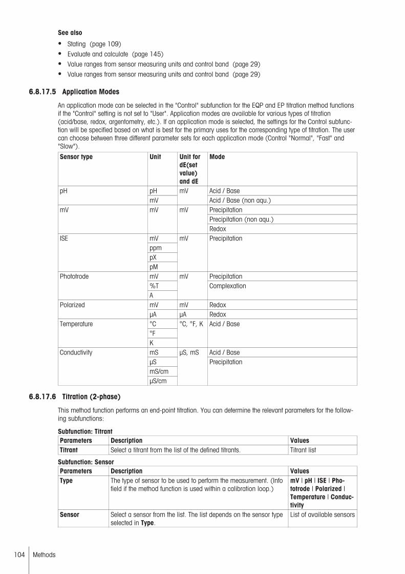
See also
● Stating (page 109)● Evaluate and calculate (page 145)● Value ranges from sensor measuring units and control band (page 29)● Value ranges from sensor measuring units and control band (page 29)
6.8.17.5 Application Modes
An application mode can be selected in the "Control" subfunction for the EQP and EP titration method functionsif the "Control" setting is not set to "User". Application modes are available for various types of titration(acid/base, redox, argentometry, etc.). If an application mode is selected, the settings for the Control subfunction will be specified based on what is best for the primary uses for the corresponding type of titration. The usercan choose between three different parameter sets for each application mode (Control "Normal", "Fast" and"Slow").
Sensor type Unit Unit fordE(setvalue)and dE
Mode
pH Acid / BasepHmV
mVAcid / Base (non aqu.)PrecipitationPrecipitation (non aqu.)
mV mV mV
RedoxmVppmpX
ISE
pM
mV Precipitation
mV Precipitation%T
Phototrode
A
mVComplexation
mV mV RedoxPolarizedµA µA Redox°C°F
Temperature
K
°C, °F, K Acid / Base
mS Acid / BaseµSmS/cm
Conductivity
µS/cm
µS, mSPrecipitation
6.8.17.6 Titration (2-phase)
This method function performs an end-point titration. You can determine the relevant parameters for the following subfunctions:
Subfunction: TitrantParameters Description ValuesTitrant Select a titrant from the list of the defined titrants. Titrant list
Subfunction: SensorParameters Description ValuesType The type of sensor to be used to perform the measurement. (Info
field if the method function is used within a calibration loop.)mV | pH | ISE | Phototrode | Polarized |Temperature | Conductivity
Sensor Select a sensor from the list. The list depends on the sensor typeselected in Type.
List of available sensors
104 Methods

Unit The unit of measure to be used for the measurement; the unit willdepend on the sensor type selected.
mV | pH | pM | pX |ppm | %T | A | µA | °C |K | °F | µS/cm | mS/cm |µS | mS
Indication Defines how to do the indication. Depending on the unit of measure: [mV] = Voltametric, [µA] = Amperometric.
Voltametric | Amperometric
Ipol Ipol is the polarization current, in [µA], for the voltametric indication.
0.0…24.0
Upol Defines the polarization voltage [mV], for an amperometric indication.
Only for polarized sensors and Indication = Amperometric.
0…2000.0
Subfunction: Temperature acquisitionParameters Description ValuesTemperatureacquisition
Defines whether to record the temperature, with the aid of a temperature sensor, during the execution of the analysis function.
Yes | No
Temperaturesensor
Defines which temperature sensor to use for the temperatureacquisition.
Only for Temperature acquisition = Yes.
Sensor list
Unit Defines the temperature unit to be used. °C | K | °F
Subfunction: StirParameters Description ValuesSpeed Defines the stirring speed in [%]. 0…100
Subfunction: PredispenseParameters Description ValuesMode Specifies the type of addition:
Volume: predispenses a specific volume.Potential: system predispenses a substance until a certainpotential is reached.Factor: A multiple of the sample size is predispensed.None: does not predispense.
Volume | Potential |Factor | None
Volume The volume to be predispensed in [mL].
Only for Mode = Volume.
0.0001…1000 | Auxiliary value | Formula
Potential The potential at which predispensing is stopped.
Only for Mode = Potential.
Depends on the sensor
Factor The system calculates the predispensing volume by multiplyingthe factor by the sample size.
For Mode = Factor only.
0…105 | Auxiliary value | Formula
Wait time Defines a waiting time, in [sec].After predispensing or, if Mode = None, before the start of titration.
0…32000
Subfunction: ControlParameters Description ValuesEnd point type Absolute: Titration is ended when the absolute measured value is
reached.Relative: The system will take into consideration the differencebetween the desired end point and the measured value at thestart of the titration.
Absolute | Relative
Tendency Defines the direction of change for the measured value during thetitrant addition. If the starting potential, end point and tendencyare inconsistent at the start of the analysis, the system will terminate the analysis immediately.
For End point type = Absolute only.
Positive | Negative |None
105Methods
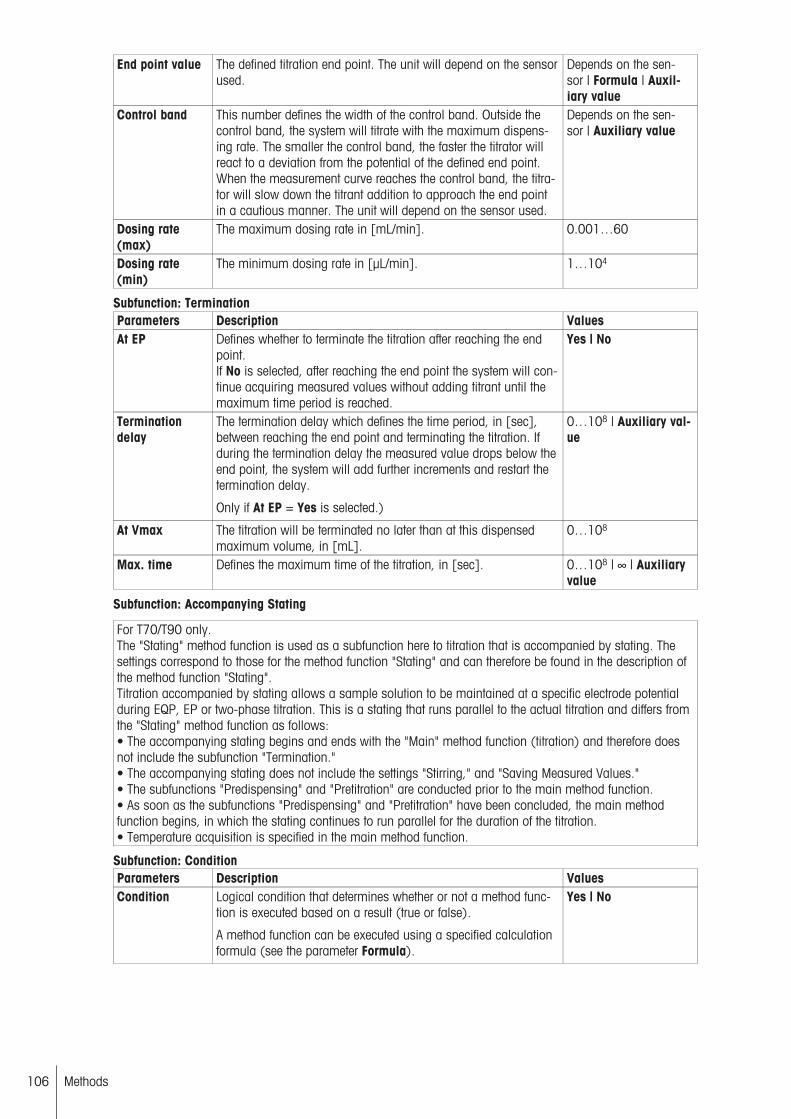
End point value The defined titration end point. The unit will depend on the sensorused.
Depends on the sensor | Formula | Auxiliary value
Control band This number defines the width of the control band. Outside thecontrol band, the system will titrate with the maximum dispensing rate. The smaller the control band, the faster the titrator willreact to a deviation from the potential of the defined end point.When the measurement curve reaches the control band, the titrator will slow down the titrant addition to approach the end pointin a cautious manner. The unit will depend on the sensor used.
Depends on the sensor | Auxiliary value
Dosing rate(max)
The maximum dosing rate in [mL/min]. 0.001…60
Dosing rate(min)
The minimum dosing rate in [µL/min]. 1…104
Subfunction: TerminationParameters Description ValuesAt EP Defines whether to terminate the titration after reaching the end
point.If No is selected, after reaching the end point the system will continue acquiring measured values without adding titrant until themaximum time period is reached.
Yes | No
Terminationdelay
The termination delay which defines the time period, in [sec],between reaching the end point and terminating the titration. Ifduring the termination delay the measured value drops below theend point, the system will add further increments and restart thetermination delay.
Only if At EP = Yes is selected.)
0…108 | Auxiliary value
At Vmax The titration will be terminated no later than at this dispensedmaximum volume, in [mL].
0…108
Max. time Defines the maximum time of the titration, in [sec]. 0…108 | ∞ | Auxiliaryvalue
Subfunction: Accompanying Stating
For T70/T90 only.The "Stating" method function is used as a subfunction here to titration that is accompanied by stating. Thesettings correspond to those for the method function "Stating" and can therefore be found in the description ofthe method function "Stating".Titration accompanied by stating allows a sample solution to be maintained at a specific electrode potentialduring EQP, EP or two-phase titration. This is a stating that runs parallel to the actual titration and differs fromthe "Stating" method function as follows:• The accompanying stating begins and ends with the "Main" method function (titration) and therefore doesnot include the subfunction "Termination."• The accompanying stating does not include the settings "Stirring," and "Saving Measured Values."• The subfunctions "Predispensing" and "Pretitration" are conducted prior to the main method function.• As soon as the subfunctions "Predispensing" and "Pretitration" have been concluded, the main methodfunction begins, in which the stating continues to run parallel for the duration of the titration.• Temperature acquisition is specified in the main method function.
Subfunction: ConditionParameters Description ValuesCondition Logical condition that determines whether or not a method func
tion is executed based on a result (true or false).
A method function can be executed using a specified calculationformula (see the parameter Formula).
Yes | No
106 Methods

Formula Here you can enter a formula whose result (true or false) willdetermine the execution of the method function.
The method function is only executed if the result is "True", andonly for Condition = Yes.
Mathematical calculation
See also
● Stating (page 109)● Evaluate and calculate (page 145)● Value ranges from sensor measuring units and control band (page 29)● Value ranges from sensor measuring units and control band (page 29)
6.8.17.7 Titration (LearnEQP)
Learn titration (EQP) is used to determine the best parameters for carrying out an EQP titration. As soon as thesettings have been successfully recorded, the titration detection in the method is converted to a normal EQPtitration with the recorded settings.You can determine the relevant parameters for the following subfunctions:
Subfunction: TitrantParameters Description ValuesTitrant Select a titrant from the list of the defined titrants. Titrant list
Subfunction: SensorParameters Description ValuesType The type of sensor to be used to perform the measurement. (Info
field if the method function is used within a calibration loop.)mV | pH | ISE | Phototrode | Polarized |Temperature | Conductivity
Sensor Select a sensor from the list. The list depends on the sensor typeselected in Type.
List of available sensors
Unit The unit of measure to be used for the measurement; the unit willdepend on the sensor type selected.
mV | pH | pM | pX |ppm | %T | A | µA | °C |K | °F | µS/cm | mS/cm |µS | mS
Indication Defines how to do the indication. Depending on the unit of measure: [mV] = Voltametric, [µA] = Amperometric.
Voltametric | Amperometric
Ipol Ipol is the polarization current, in [µA], for the voltametric indication.
0.0…24.0
Upol Defines the polarization voltage [mV], for an amperometric indication.
Only for polarized sensors and Indication = Amperometric.
0…2000.0
Subfunction: Temperature acquisitionParameters Description ValuesTemperatureacquisition
Defines whether to record the temperature, with the aid of a temperature sensor, during the execution of the analysis function.
Yes | No
Temperaturesensor
Defines which temperature sensor to use for the temperatureacquisition.
Only for Temperature acquisition = Yes.
Sensor list
Unit Defines the temperature unit to be used. °C | K | °F
Subfunction: StirParameters Description ValuesSpeed Defines the stirring speed in [%]. 0…100
107Methods

Subfunction: ConditionParameters Description ValuesCondition Logical condition that determines whether or not a method func
tion is executed based on a result (true or false).
A method function can be executed using a specified calculationformula (see the parameter Formula).
Yes | No
Formula Here you can enter a formula whose result (true or false) willdetermine the execution of the method function.
The method function is only executed if the result is "True", andonly for Condition = Yes.
Mathematical calculation
See also
● Evaluate and calculate (page 145)
6.8.17.8 Titration (KF Vol)
Carries out a Karl Fischer titration. You can determine the relevant parameters for the following subfunctions:
Subfunction: TitrantParameters Description ValuesTitrant Select a titrant from the list of the defined titrants. Titrant list
Subfunction: SensorParameters Description ValuesSensor Select a sensor from the list. The list depends on the sensor type
selected in Type.List of available sensors
For Karl Fischer titrations, only polarized sensors can be selected.
Ipol Ipol is the polarization current, in [µA], for the voltametric indication.
0.0…24.0
Subfunction: StirParameters Description ValuesSpeed Defines the stirring speed in [%]. 0…100
Subfunction: PredispenseParameters Description ValuesMode Specifies the type of addition:
Volume: predispenses a specific volume.None: does not predispense.
Volume | None
Volume The volume to be predispensed in [mL].
Only for Mode = Volume.
0.0001…1000 | Auxiliary value | Formula
Wait time Defines a waiting time, in [sec].After predispensing or, if Mode = None, before the start of titration.
0…32000
Subfunction: ControlThe maximum dosing rates are dependent on the size of the burette. The user is able to edit the entire valuerange. When Start is pressed, the system then checks whether the entered values are actually possible with thecurrent burette size.
Burette size [ml] Maximum dosingrate [mL/min]
1 35 1510 3020 60
108 Methods
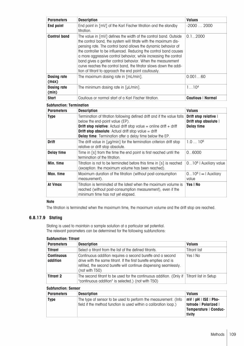
Parameters Description ValuesEnd point End point in [mV] of the Karl Fischer titration and the standby
titration.-2000 … 2000
Control band The value in [mV] defines the width of the control band. Outsidethe control band, the system will titrate with the maximum dispensing rate. The control band allows the dynamic behavior ofthe controller to be influenced. Reducing the control band causesa more aggressive control behavior, while increasing the controlband gives a gentler control behavior. When the measurementcurve reaches the control band, the titrator slows down the addition of titrant to approach the end point cautiously.
0.1...2000
Dosing rate(max)
The maximum dosing rate in [mL/min]. 0.001…60
Dosing rate(min)
The minimum dosing rate in [µL/min]. 1…104
Start Cautious or normal start of a Karl Fischer titration. Cautious | Normal
Subfunction: TerminationParameters Description ValuesType Termination of titration following defined drift and if the value falls
below the end-point value (EP).Drift stop relative: Actual drift stop value = online drift + driftDrift stop absolute: Actual drift stop value = driftDelay time: Termination after a delay time below the EP.
Drift stop relative |Drift stop absolute |Delay time
Drift The drift value in [µg/min] for the termination criterion drift stoprelative or drift stop absolute.
1.0 ... 106
Delay time Time in [s] from the time the end point is first reached until thetermination of the titration.
0...6000
Min. time Titration is not to be terminated before this time in [s] is reached(exception: the maximum volume has been reached).
0...108 | Auxiliary value
Max. time Maximum duration of the titration (without post-consumptionmeasurement).
0...108 | ∞ | Auxiliaryvalue
At Vmax Titration is terminated at the latest when the maximum volume isreached (without post-consumption measurement), even if theminimum time has not yet elapsed.
Yes | No
NoteThe titration is terminated when the maximum time, the maximum volume and the drift stop are reached.
6.8.17.9 Stating
Stating is used to maintain a sample solution at a particular set potential.The relevant parameters can be determined for the following subfunctions:
Subfunction: TitrantParameters Description ValuesTitrant Select a titrant from the list of the defined titrants. Titrant listContinuousaddition
Continuous addition requires a second burette and a seconddrive with the same titrant. If the first burette empties and isrefilled, the second burette will continue dispensing seamlessly.(not with T50)
Yes | No
Titrant 2 The second titrant to be used for the continuous addition. (Only if"continuous addition" is selected.) (not with T50)
Titrant list in Setup
Subfunction: SensorParameters Description ValuesType The type of sensor to be used to perform the measurement. (Info
field if the method function is used within a calibration loop.)mV | pH | ISE | Phototrode | Polarized |Temperature | Conductivity
109Methods
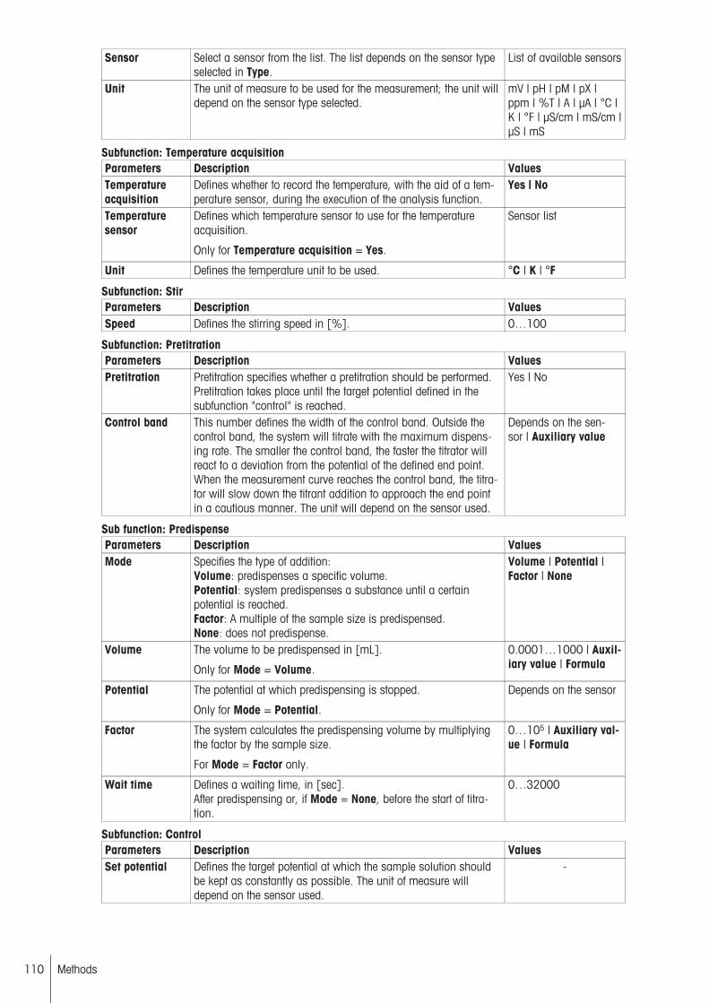
Sensor Select a sensor from the list. The list depends on the sensor typeselected in Type.
List of available sensors
Unit The unit of measure to be used for the measurement; the unit willdepend on the sensor type selected.
mV | pH | pM | pX |ppm | %T | A | µA | °C |K | °F | µS/cm | mS/cm |µS | mS
Subfunction: Temperature acquisitionParameters Description ValuesTemperatureacquisition
Defines whether to record the temperature, with the aid of a temperature sensor, during the execution of the analysis function.
Yes | No
Temperaturesensor
Defines which temperature sensor to use for the temperatureacquisition.
Only for Temperature acquisition = Yes.
Sensor list
Unit Defines the temperature unit to be used. °C | K | °F
Subfunction: StirParameters Description ValuesSpeed Defines the stirring speed in [%]. 0…100
Subfunction: PretitrationParameters Description ValuesPretitration Pretitration specifies whether a pretitration should be performed.
Pretitration takes place until the target potential defined in thesubfunction "control" is reached.
Yes | No
Control band This number defines the width of the control band. Outside thecontrol band, the system will titrate with the maximum dispensing rate. The smaller the control band, the faster the titrator willreact to a deviation from the potential of the defined end point.When the measurement curve reaches the control band, the titrator will slow down the titrant addition to approach the end pointin a cautious manner. The unit will depend on the sensor used.
Depends on the sensor | Auxiliary value
Sub function: PredispenseParameters Description ValuesMode Specifies the type of addition:
Volume: predispenses a specific volume.Potential: system predispenses a substance until a certainpotential is reached.Factor: A multiple of the sample size is predispensed.None: does not predispense.
Volume | Potential |Factor | None
Volume The volume to be predispensed in [mL].
Only for Mode = Volume.
0.0001…1000 | Auxiliary value | Formula
Potential The potential at which predispensing is stopped.
Only for Mode = Potential.
Depends on the sensor
Factor The system calculates the predispensing volume by multiplyingthe factor by the sample size.
For Mode = Factor only.
0…105 | Auxiliary value | Formula
Wait time Defines a waiting time, in [sec].After predispensing or, if Mode = None, before the start of titration.
0…32000
Subfunction: ControlParameters Description ValuesSet potential Defines the target potential at which the sample solution should
be kept as constantly as possible. The unit of measure willdepend on the sensor used.
-
110 Methods

Control band This number defines the width of the control band. Outside thecontrol band, the system will titrate with the maximum dispensing rate. The smaller the control band, the faster the titrator willreact to a deviation from the potential of the defined end point.When the measurement curve reaches the control band, the titrator will slow down the titrant addition to approach the end pointin a cautious manner. The unit will depend on the sensor used.
Depends on the sensor | Auxiliary value
Tendency Defines the direction in which the sensor signal should be shiftedby the titrant addition.
Positive | Negative
Dosing rate(max)
The maximum dosing rate in [mL/min]. 0.001…60
Dosing rate(min)
The minimum dosing rate in [µL/min]. 1…104
Subfunction: MonitoringParameters Description ValuesMonitoring Defines whether to monitor the sensor signal or temperature dur
ing the main stating process.Yes | No
Signal If you want to run monitoring, this is where you specify whetherto monitor the sensor signal or the temperature. (For "monitor" ="yes" only.)
Sensor signal | Temperature
Lower limit Defines the lower limit of the range within which the signal ortemperature will be allowed to vary. If the signal or temperatureviolate this range, that will trigger the defined "Action". The unit ofmeasure will depend on the sensor used.
-
Upper limit Defines the upper limit of the range within which the signal ortemperature will be allowed to vary. If the signal or temperatureviolate this range, that will trigger the defined "Action". The unit ofmeasure will depend on the sensor used.
-
Action Defines an action for violations of the upper or lower monitoringparameters.• "Terminate": Stating will be terminated.• "Manual:" The stating will be interrupted and a message willappear on the display. The user can terminate or continue thestating process.• "Automatic": Stating will be interrupted and continued when themonitoring parameters have returned to within the limits.
Automatic | Manual |Terminate
Subfunction: TerminationAt Vmax The volume, in [mL], after the dispensing of which the stating
will be terminated.0.01…1000
From t(min) Specifies whether to define a time for the earliest possible termination of the stating.
Yes | No
t(min) The earliest time, in [min], at which termination can take place, ifthe maximum volume has not yet been reached. (Only if "fromt(min)" = "yes" is selected.)
0.1…106
At t(max) Specifies whether to define a time at which the stating will be terminated if it has not ended already.
Yes | No
t(max) The time, in [min], at which the stating will be terminated if it hasnot ended already.(Only if "At "t(max)" = "Yes" is selected.)
0.1…106
After statingduration
Specifies whether to define a time period after which the statingwill be terminated after reaching the end point for the first time.
Yes | No
Stating duration The time period, in [min], after which the stating will be terminated after reaching the first end point. If defined, "t(min)" will betaken into consideration.(Only if "After stating duration" = "Yes" is selected.)
0.1…106
At minimum rate Defines whether to take a minimum rate into consideration whichwill terminate the stating if violated.
Yes | No
111Methods
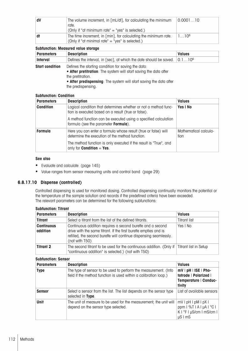
dV The volume increment, in [mL/dt], for calculating the minimumrate.(Only if "at minimum rate" = "yes" is selected.)
0.0001…10
dt The time increment, in [min], for calculating the minimum rate.(Only if "at minimal rate" = "yes" is selected.)
1…106
Subfunction: Measured value storageParameters Description ValuesInterval Defines the interval, in [sec], at which the date should be saved. 0.1…106
Start condition Defines the starting condition for saving the data:• After pretitration: The system will start saving the data afterthe pretitration.• After predispensing: The system will start saving the data afterthe predispensing.
Subfunction: ConditionParameters Description ValuesCondition Logical condition that determines whether or not a method func
tion is executed based on a result (true or false).
A method function can be executed using a specified calculationformula (see the parameter Formula).
Yes | No
Formula Here you can enter a formula whose result (true or false) willdetermine the execution of the method function.
The method function is only executed if the result is "True", andonly for Condition = Yes.
Mathematical calculation
See also
● Evaluate and calculate (page 145)● Value ranges from sensor measuring units and control band (page 29)
6.8.17.10 Dispense (controlled)
Controlled dispensing is used for monitored dosing. Controlled dispensing continually monitors the potential orthe temperature of the sample solution and records if the predefined criteria have been exceeded.The relevant parameters can be determined for the following subfunctions:
Subfunction: TitrantParameters Description ValuesTitrant Select a titrant from the list of the defined titrants. Titrant listContinuousaddition
Continuous addition requires a second burette and a seconddrive with the same titrant. If the first burette empties and isrefilled, the second burette will continue dispensing seamlessly.(not with T50)
Yes | No
Titrant 2 The second titrant to be used for the continuous addition. (Only if"continuous addition" is selected.) (not with T50)
Titrant list in Setup
Subfunction: SensorParameters Description ValuesType The type of sensor to be used to perform the measurement. (Info
field if the method function is used within a calibration loop.)mV | pH | ISE | Phototrode | Polarized |Temperature | Conductivity
Sensor Select a sensor from the list. The list depends on the sensor typeselected in Type.
List of available sensors
Unit The unit of measure to be used for the measurement; the unit willdepend on the sensor type selected.
mV | pH | pM | pX |ppm | %T | A | µA | °C |K | °F | µS/cm | mS/cm |µS | mS
112 Methods

Subfunction: Temperature acquisition Parameters Description ValuesTemperatureacquisition
Defines whether to record the temperature, with the aid of a temperature sensor, during the execution of the analysis function.
Yes | No
Temperaturesensor
Defines which temperature sensor to use for the temperatureacquisition.
Only for Temperature acquisition = Yes.
Sensor list
Unit Defines the temperature unit to be used. °C | K | °F
Subfunction: StirParameters Description ValuesSpeed Defines the stirring speed in [%]. 0…100
Subfunction: DispensingVolume The volume to be dispensed, in [mL]. 0.001 … 1000 | Auxil
iary value | FormulaDosing rate The dosing speed, in [mL/min]. If the number is above the maxi
mum value possible, the system will dispense at the maximumrate. You can also select a burette type-dependent maximumnumber.
0.001…60
t(max) Defines a time period, in [min], after which dispensing will beterminated, even if the volume has not yet been reached.
0.1…106
Subfunction: MonitoringParameters Description ValuesMonitoring Defines whether to monitor the sensor signal or temperature dur
ing the main stating process.Yes | No
Signal If you want to run monitoring, this is where you specify whetherto monitor the sensor signal or the temperature. (For "monitor" ="yes" only.)
Sensor signal | Temperature
Lower limit Defines the lower limit of the range within which the signal ortemperature will be allowed to vary. If the signal or temperatureviolate this range, that will trigger the defined "Action". The unit ofmeasure will depend on the sensor used.
-
Upper limit Defines the upper limit of the range within which the signal ortemperature will be allowed to vary. If the signal or temperatureviolate this range, that will trigger the defined "Action". The unit ofmeasure will depend on the sensor used.
-
Action Defines an action for violations of the upper or lower monitoringparameters.• "Terminate": Stating will be terminated.• "Manual:" The stating will be interrupted and a message willappear on the display. The user can terminate or continue thestating process.• "Automatic": Stating will be interrupted and continued when themonitoring parameters have returned to within the limits.
Automatic | Manual |Terminate
Subfunction: Saving measured values Parameters Description ValuesInterval Defines the interval, in [sec], at which the date should be saved. 0.1…106
Subfunction: ConditionParameters Description ValuesCondition Logical condition that determines whether or not a method func
tion is executed based on a result (true or false).
A method function can be executed using a specified calculationformula (see the parameter Formula).
Yes | No
113Methods

Formula Here you can enter a formula whose result (true or false) willdetermine the execution of the method function.
The method function is only executed if the result is "True", andonly for Condition = Yes.
Mathematical calculation
See also
● Evaluate and calculate (page 145)
6.8.18 Calculation
For converting the titration results.
Parameters Description ValuesResult type If the result type "Automatic" is selected, a predefined result from
the proposal list is used. The parameters "Result", "Unit", "Formula", and "Constant" are adjusted automatically in accordancewith the entry type selected in the method function sample (KF)and cannot be changed.If "User defined" is selected, all parameters can be edited. Youcan also select a predefined result type from the results proposallist.
Automatic | User defined
Result After selecting a result from the dropdown list, the system willautomatically set the "Result unit", "Formula" and "Constant"parameters. But you will be able to make any changes to themthat you would like without having the system adjust the otherparameters. You can also enter any number.
Results list | Arbitrary
Result unit The unit of the result. (Is not automatically adjusted after changesto "Formula" or "Constant".) You can also use "Proposal" toselect from a predefined suggestion list.
Device list | Arbitrary
Formula The formula for calculating the result. You can use "Results proposals" to select from a predefined suggestion list.
Formula list | Arbitrary
Constant Definition of the C constant which can be used in the calculation.The constant can itself be a formula. You can also use"Proposal" to select from a predefined suggestion list.
Constants list | Arbitrary
M Defines the molar mass of the substance [g/mol]. List of concentration/titer standards andsubstances
Decimal places The number of decimal places for the result. 0…6Result limits Defines whether limits should be observed for the result. If this
function is activated, there will be a message in the record if theresult falls outside the defined limits.
Yes | No
Lower limit Defines the lower result limit.Appears only if "result limits" = "yes" was selected.
-108 … 108
Upper limit Defines the upper result limit.Appears only if "result limit" = "yes" was selected.
-108…108
Interruption outside limits
Determines whether the method should be interrupted if a valuelies outside the defined limits (only appears if the "Limits" parameter has been activated).A message (which must be acknowledged) appears advisingthat the process has been interrupted during the time that themessage is displayed.
Yes | No
Record statistics Specifies whether statistics should also be issued with the resultsin the report along with the result.The statistics are not printed, if in the method function "Protocol"the parameter "Results" = "No" is selected.
Yes | No
114 Methods
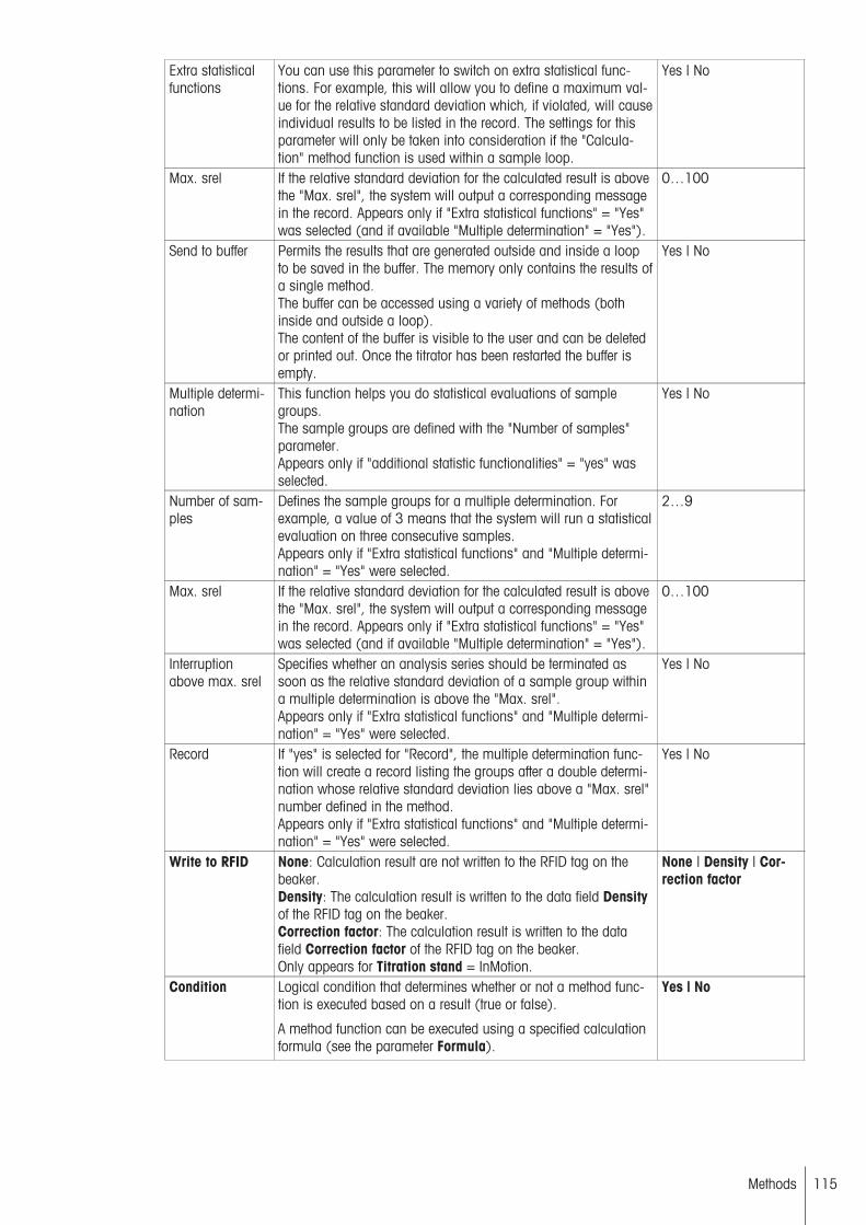
Extra statisticalfunctions
You can use this parameter to switch on extra statistical functions. For example, this will allow you to define a maximum value for the relative standard deviation which, if violated, will causeindividual results to be listed in the record. The settings for thisparameter will only be taken into consideration if the "Calculation" method function is used within a sample loop.
Yes | No
Max. srel If the relative standard deviation for the calculated result is abovethe "Max. srel", the system will output a corresponding messagein the record. Appears only if "Extra statistical functions" = "Yes"was selected (and if available "Multiple determination" = "Yes").
0…100
Send to buffer Permits the results that are generated outside and inside a loopto be saved in the buffer. The memory only contains the results ofa single method.The buffer can be accessed using a variety of methods (bothinside and outside a loop).The content of the buffer is visible to the user and can be deletedor printed out. Once the titrator has been restarted the buffer isempty.
Yes | No
Multiple determination
This function helps you do statistical evaluations of samplegroups.The sample groups are defined with the "Number of samples"parameter.Appears only if "additional statistic functionalities" = "yes" wasselected.
Yes | No
Number of samples
Defines the sample groups for a multiple determination. Forexample, a value of 3 means that the system will run a statisticalevaluation on three consecutive samples.Appears only if "Extra statistical functions" and "Multiple determination" = "Yes" were selected.
2…9
Max. srel If the relative standard deviation for the calculated result is abovethe "Max. srel", the system will output a corresponding messagein the record. Appears only if "Extra statistical functions" = "Yes"was selected (and if available "Multiple determination" = "Yes").
0…100
Interruptionabove max. srel
Specifies whether an analysis series should be terminated assoon as the relative standard deviation of a sample group withina multiple determination is above the "Max. srel".Appears only if "Extra statistical functions" and "Multiple determination" = "Yes" were selected.
Yes | No
Record If "yes" is selected for "Record", the multiple determination function will create a record listing the groups after a double determination whose relative standard deviation lies above a "Max. srel"number defined in the method.Appears only if "Extra statistical functions" and "Multiple determination" = "Yes" were selected.
Yes | No
Write to RFID None: Calculation result are not written to the RFID tag on thebeaker.Density: The calculation result is written to the data field Densityof the RFID tag on the beaker.Correction factor: The calculation result is written to the datafield Correction factor of the RFID tag on the beaker.Only appears for Titration stand = InMotion.
None | Density | Correction factor
Condition Logical condition that determines whether or not a method function is executed based on a result (true or false).
A method function can be executed using a specified calculationformula (see the parameter Formula).
Yes | No
115Methods

Formula Here you can enter a formula whose result (true or false) willdetermine the execution of the method function.
The method function is only executed if the result is "True", andonly for Condition = Yes.
Mathematical calculation
See also
● Evaluate and calculate (page 145)
6.8.19 End of sample
The "End of Sample" method function closes a sample loop. A sample loop refers to the range of a methodthrough which a sample series will pass for each sample. The commencement of a sample loop is specifiedusing the "Sample" method function.
Parameters Description ValuesOpen series Determines whether the subsequent method functions are
processed after the method function "End of sample", or if thetitrator returns to Standby mode.
Yes | No
The "Open series" parameter is only available for Karl Fischer titration without the Stromboli oven samplechanger. If "Open series" is set, the titrator enters "Standby" mode at the end of the analysis and the methodremains active. If "Open series" is not set, the method is ended after the final sample.
6.8.20 Titer
The "Titer" method function is only available outside a loop. This method function assigns the result of a sample loop to a titer and updates the value stored in Setup.
Parameters Description ValuesTITER= Specifies for how many results the titer should be determined.
(For i=1, i does not have to be defined.)Mean[Ri], i=1…30
Limits Determines whether limits should be taken into account foracquisition of a value. If the value is outside these limits, the value is not transferred to Setup.
Yes | No
Interruption outside limits
Determines whether the method should be interrupted if a valuelies outside the defined limits (only appears if the "Limits" parameter has been activated).A message (which must be acknowledged) appears advisingthat the process has been interrupted during the time that themessage is displayed.
Yes | No
Lower limit Defines the lower limit of a value. Appears only if the "limits" ="yes" setting was selected.
0…100
Upper limit Defines the upper limit of the concentration limit. 0.1…100Condition Logical condition that determines whether or not a method func
tion is executed based on a result (true or false).
A method function can be executed using a specified calculationformula (see the parameter Formula).
Yes | No
Formula Here you can enter a formula whose result (true or false) willdetermine the execution of the method function.
The method function is only executed if the result is "True", andonly for Condition = Yes.
Mathematical calculation
See also
● Evaluate and calculate (page 145)
6.8.21 Calibration
This method function assigns the result of a calibration loop to a sensor and updates the sensor setup. Calibration is only performed outside a loop.
116 Methods

Parameters Description ValuesLimits Determines whether limits should be taken into account for
acquisition of a value. If the value is outside these limits, the value is not transferred to Setup.
Yes | No
Interruption outside limits
Determines whether the method should be interrupted if a valuelies outside the defined limits (only appears if the "Limits" parameter has been activated).A message (which must be acknowledged) appears advisingthat the process has been interrupted during the time that themessage is displayed.
Yes | No
In cases of segmented calibration for pH and ISE sensors, the limits will be defined and observed for each segment.
Depending on the sensor type (pH, ISE, conductivity), if the "Limits" checkbox is activated, the following parameters can be determined (100% represents -59.16 mV/pH (sensor type: pH) or to -59.16 mV/[unit]) /Ioncharge (sensor type: ISE). The unit corresponds to the unit specified in the previous method function, "Sample(Calib)". (For temperature sensors, only the two info fields for the minimum and maximum zero point are displayed.)
For pH and ISE sensors:
Parameters Description ValuesMin. slope 1-8 The lower limit for the slope, in [%]. (100% refers to -59.16
mV/pH.)10…200
Max. slope 1-8 The upper limit for the slope, in [%]. 10…200Min. zero point1-8
The lower limit for the zero point. -100…100
Max. zero point1-8
The upper limit for the zero point. -100…100
For conductivity sensors:
Min. cell constant
Defines the lower limit for the cell constant of a conductivity sensor, in [1/cm].
0…100
Max. cell constant
Defines the upper limit for the cell constant of a conductivity sensor, in [1/cm].
0…100
Condition Logical condition that determines whether or not a method function is executed based on a result (true or false).
A method function can be executed using a specified calculationformula (see the parameter Formula).
Yes | No
Formula Here you can enter a formula whose result (true or false) willdetermine the execution of the method function.
The method function is only executed if the result is "True", andonly for Condition = Yes.
Mathematical calculation
See also
● Evaluate and calculate (page 145)
6.8.22 Auxiliary value
This method function assigns a result or arbitrary value to an auxiliary value.
Parameters Description ValuesName Specify a descriptive name of your choice. ArbitraryFormula H= Here you can enter a formula that will be used to convert the
result of the sample loop to the auxiliary value. You can alsoenter a number or an auxiliary value.
Formula (see "Evaluation and calculation(page 145)") | AuxiliaryValue | Number
Limits Determines whether limits should be taken into account foracquisition of a value. If the value is outside these limits, the value is not transferred to Setup.
Yes | No
117Methods
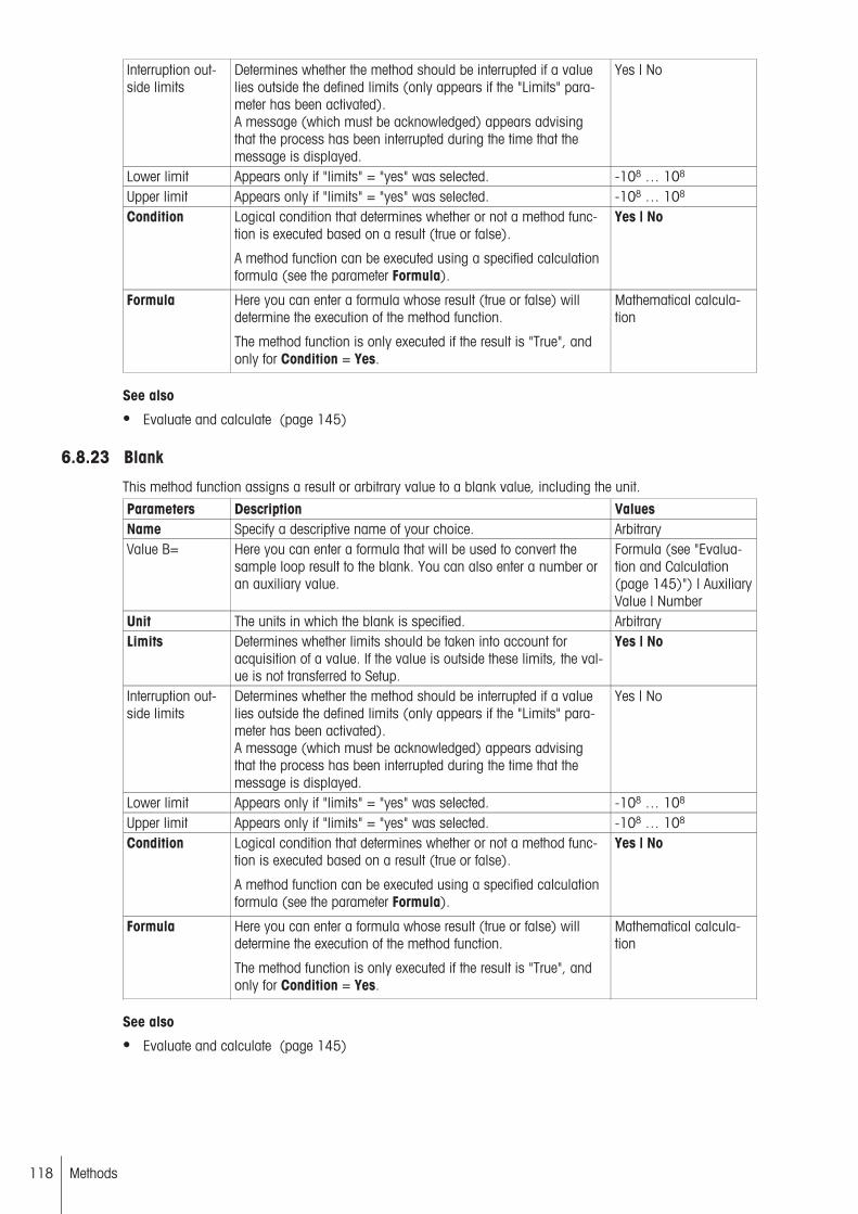
Interruption outside limits
Determines whether the method should be interrupted if a valuelies outside the defined limits (only appears if the "Limits" parameter has been activated).A message (which must be acknowledged) appears advisingthat the process has been interrupted during the time that themessage is displayed.
Yes | No
Lower limit Appears only if "limits" = "yes" was selected. -108 … 108
Upper limit Appears only if "limits" = "yes" was selected. -108 … 108
Condition Logical condition that determines whether or not a method function is executed based on a result (true or false).
A method function can be executed using a specified calculationformula (see the parameter Formula).
Yes | No
Formula Here you can enter a formula whose result (true or false) willdetermine the execution of the method function.
The method function is only executed if the result is "True", andonly for Condition = Yes.
Mathematical calculation
See also
● Evaluate and calculate (page 145)
6.8.23 Blank
This method function assigns a result or arbitrary value to a blank value, including the unit.
Parameters Description ValuesName Specify a descriptive name of your choice. ArbitraryValue B= Here you can enter a formula that will be used to convert the
sample loop result to the blank. You can also enter a number oran auxiliary value.
Formula (see "Evaluation and Calculation(page 145)") | AuxiliaryValue | Number
Unit The units in which the blank is specified. ArbitraryLimits Determines whether limits should be taken into account for
acquisition of a value. If the value is outside these limits, the value is not transferred to Setup.
Yes | No
Interruption outside limits
Determines whether the method should be interrupted if a valuelies outside the defined limits (only appears if the "Limits" parameter has been activated).A message (which must be acknowledged) appears advisingthat the process has been interrupted during the time that themessage is displayed.
Yes | No
Lower limit Appears only if "limits" = "yes" was selected. -108 … 108
Upper limit Appears only if "limits" = "yes" was selected. -108 … 108
Condition Logical condition that determines whether or not a method function is executed based on a result (true or false).
A method function can be executed using a specified calculationformula (see the parameter Formula).
Yes | No
Formula Here you can enter a formula whose result (true or false) willdetermine the execution of the method function.
The method function is only executed if the result is "True", andonly for Condition = Yes.
Mathematical calculation
See also
● Evaluate and calculate (page 145)
118 Methods
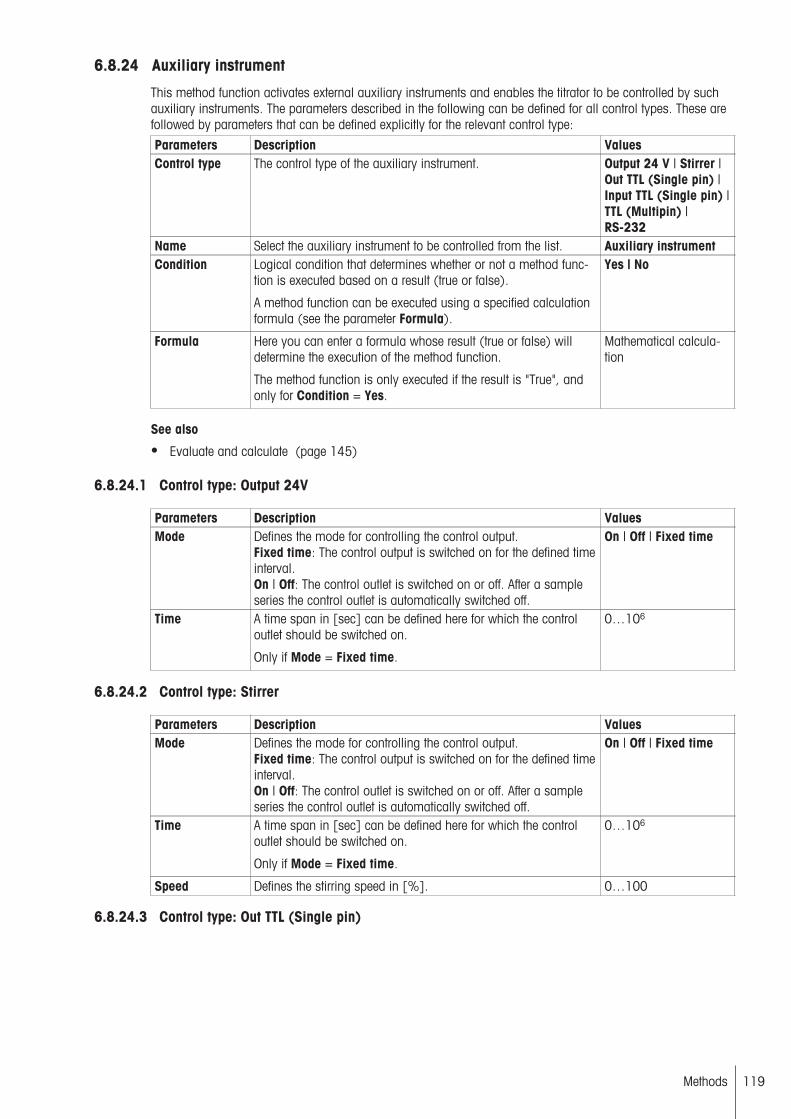
6.8.24 Auxiliary instrument
This method function activates external auxiliary instruments and enables the titrator to be controlled by suchauxiliary instruments. The parameters described in the following can be defined for all control types. These arefollowed by parameters that can be defined explicitly for the relevant control type:
Parameters Description ValuesControl type The control type of the auxiliary instrument. Output 24 V | Stirrer |
Out TTL (Single pin) |Input TTL (Single pin) |TTL (Multipin) |RS-232
Name Select the auxiliary instrument to be controlled from the list. Auxiliary instrumentCondition Logical condition that determines whether or not a method func
tion is executed based on a result (true or false).
A method function can be executed using a specified calculationformula (see the parameter Formula).
Yes | No
Formula Here you can enter a formula whose result (true or false) willdetermine the execution of the method function.
The method function is only executed if the result is "True", andonly for Condition = Yes.
Mathematical calculation
See also
● Evaluate and calculate (page 145)
6.8.24.1 Control type: Output 24V
Parameters Description ValuesMode Defines the mode for controlling the control output.
Fixed time: The control output is switched on for the defined timeinterval.On | Off: The control outlet is switched on or off. After a sampleseries the control outlet is automatically switched off.
On | Off | Fixed time
Time A time span in [sec] can be defined here for which the controloutlet should be switched on.
Only if Mode = Fixed time.
0…106
6.8.24.2 Control type: Stirrer
Parameters Description ValuesMode Defines the mode for controlling the control output.
Fixed time: The control output is switched on for the defined timeinterval.On | Off: The control outlet is switched on or off. After a sampleseries the control outlet is automatically switched off.
On | Off | Fixed time
Time A time span in [sec] can be defined here for which the controloutlet should be switched on.
Only if Mode = Fixed time.
0…106
Speed Defines the stirring speed in [%]. 0…100
6.8.24.3 Control type: Out TTL (Single pin)
119Methods

Parameters Description ValuesMode Defines the mode for controlling the control output. For TTL sig
nals, the number and type of the output signals is determined.Fixed time: The control output is switched on for the defined timeperiod.On | Off: The control output is switched on or off.Input controlled: A signal received at the control inlet controls thecontrol outlet. The Auxiliary instrument function is terminated assoon as the signal changes at the control input or after a definedmaximum time has expired.Sequential: The control output runs through a defined sequence.
On | Off | Fixed time |Input controlled |Sequential
Time A time span in [sec] can be defined here for which the controloutlet should be switched on.
Only if Mode = Fixed time.
0…106
Input Select the auxiliary instrument to serve as the signal input (control input).
Only if Mode = Input controlled.
Auxiliary instrument
Output signal Normal: The signal is transmitted without conversion.Inverted: The signal is transmitted in inverted form.
Only if Mode = Input controlled.
Normal | Inverted
Max. time The maximum waiting time for a signal change, in [sec].After it expires, the method is continued even if no signal changewas detected.
Only for signal inputs.
0…106
Number of pulses
The number of impulses in the planned sequence.
Only if Mode = Sequential.
0…104
Pulse duration The duration of a pulse in [sec] (time switched on + time switched off).
Only if Mode = Sequential.
0…106
Interval Defines the time span, in [sec], between two impulse starts.
Only if Mode = Sequential.
0…106 | 0…104
6.8.24.4 Control type: Input TTL (single pin)
Parameters Description ValuesInput signal Indicates whether an rising or a falling input signal should be
detected.Rising | Falling
Max. time The maximum waiting time for a signal change, in [sec].After it expires, the method is continued even if no signal changewas detected.
Only for signal inputs.
0…106
6.8.24.5 Control type: TTL (multipin)
Parameters Description ValuesInput/Output Defines the communication direction. Output | InputPin Select a pin and define the type of control.
Output: 1, 2, 3, 4 Input: 1, 2,
1…4
120 Methods
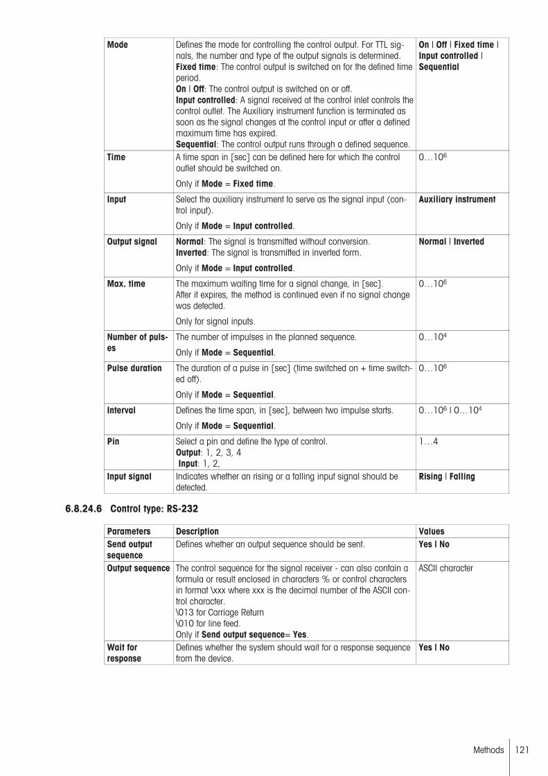
Mode Defines the mode for controlling the control output. For TTL signals, the number and type of the output signals is determined.Fixed time: The control output is switched on for the defined timeperiod.On | Off: The control output is switched on or off.Input controlled: A signal received at the control inlet controls thecontrol outlet. The Auxiliary instrument function is terminated assoon as the signal changes at the control input or after a definedmaximum time has expired.Sequential: The control output runs through a defined sequence.
On | Off | Fixed time |Input controlled |Sequential
Time A time span in [sec] can be defined here for which the controloutlet should be switched on.
Only if Mode = Fixed time.
0…106
Input Select the auxiliary instrument to serve as the signal input (control input).
Only if Mode = Input controlled.
Auxiliary instrument
Output signal Normal: The signal is transmitted without conversion.Inverted: The signal is transmitted in inverted form.
Only if Mode = Input controlled.
Normal | Inverted
Max. time The maximum waiting time for a signal change, in [sec].After it expires, the method is continued even if no signal changewas detected.
Only for signal inputs.
0…106
Number of pulses
The number of impulses in the planned sequence.
Only if Mode = Sequential.
0…104
Pulse duration The duration of a pulse in [sec] (time switched on + time switched off).
Only if Mode = Sequential.
0…106
Interval Defines the time span, in [sec], between two impulse starts.
Only if Mode = Sequential.
0…106 | 0…104
Pin Select a pin and define the type of control.Output: 1, 2, 3, 4 Input: 1, 2,
1…4
Input signal Indicates whether an rising or a falling input signal should bedetected.
Rising | Falling
6.8.24.6 Control type: RS-232
Parameters Description ValuesSend outputsequence
Defines whether an output sequence should be sent. Yes | No
Output sequence The control sequence for the signal receiver - can also contain aformula or result enclosed in characters % or control charactersin format \xxx where xxx is the decimal number of the ASCII control character.\013 for Carriage Return\010 for line feed.Only if Send output sequence= Yes.
ASCII character
Wait forresponse
Defines whether the system should wait for a response sequencefrom the device.
Yes | No
121Methods
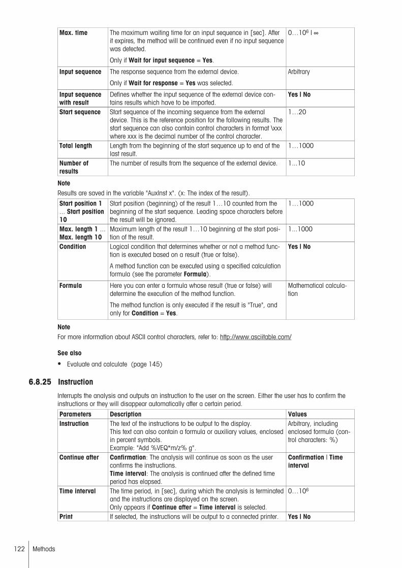
Max. time The maximum waiting time for an input sequence in [sec]. Afterit expires, the method will be continued even if no input sequencewas detected.
Only if Wait for input sequence = Yes.
0…106 | ∞
Input sequence The response sequence from the external device.
Only if Wait for response = Yes was selected.
Arbitrary
Input sequencewith result
Defines whether the input sequence of the external device contains results which have to be imported.
Yes | No
Start sequence Start sequence of the incoming sequence from the externaldevice. This is the reference position for the following results. Thestart sequence can also contain control characters in format \xxxwhere xxx is the decimal number of the control character.
1…20
Total length Length from the beginning of the start sequence up to end of thelast result.
1…1000
Number ofresults
The number of results from the sequence of the external device. 1...10
NoteResults are saved in the variable "AuxInst x". (x: The index of the result).
Start position 1... Start position10
Start position (beginning) of the result 1…10 counted from thebeginning of the start sequence. Leading space characters beforethe result will be ignored.
1…1000
Max. length 1 ...Max. length 10
Maximum length of the result 1…10 beginning at the start position of the result.
1...1000
Condition Logical condition that determines whether or not a method function is executed based on a result (true or false).
A method function can be executed using a specified calculationformula (see the parameter Formula).
Yes | No
Formula Here you can enter a formula whose result (true or false) willdetermine the execution of the method function.
The method function is only executed if the result is "True", andonly for Condition = Yes.
Mathematical calculation
NoteFor more information about ASCII control characters, refer to: http://www.asciitable.com/
See also
● Evaluate and calculate (page 145)
6.8.25 Instruction
Interrupts the analysis and outputs an instruction to the user on the screen. Either the user has to confirm theinstructions or they will disappear automatically after a certain period.
Parameters Description ValuesInstruction The text of the instructions to be output to the display.
This text can also contain a formula or auxiliary values, enclosedin percent symbols.Example: "Add %VEQ*m/z% g".
Arbitrary, includingenclosed formula (control characters: %)
Continue after Confirmation: The analysis will continue as soon as the userconfirms the instructions.Time interval: The analysis is continued after the defined timeperiod has elapsed.
Confirmation | Timeinterval
Time interval The time period, in [sec], during which the analysis is terminatedand the instructions are displayed on the screen.Only appears if Continue after = Time interval is selected.
0…106
Print If selected, the instructions will be output to a connected printer. Yes | No
122 Methods

Condition Logical condition that determines whether or not a method function is executed based on a result (true or false).
A method function can be executed using a specified calculationformula (see the parameter Formula).
Yes | No
Formula Here you can enter a formula whose result (true or false) willdetermine the execution of the method function.
The method function is only executed if the result is "True", andonly for Condition = Yes.
Mathematical calculation
See also
● Evaluate and calculate (page 145)
6.8.26 Drain
You use this method function to drain a specific volume from a sample vessel using a pump.
Parameters Description ValuesDrain pump Defines which pump is to be used for drainage. List of available pumpsDrain volume The volume to be drained, in [mL]. 0…1000 | Auxiliary
value | FormulaPump property Defines the properties for the pump used. 1-way | 1-way, two
rates | 2-way, fine rateRate Allows to reduce the pump rate.
Only if the pump supports this and if the pump is connected toan InMotion.
10…100 (2-way, finerate) | 50/100 (1-way,two rates)
Direction Defines the pump direction for a 2-way pump Forward | ReverseCondition Logical condition that determines whether or not a method func
tion is executed based on a result (true or false).
A method function can be executed using a specified calculationformula (see the parameter Formula).
Yes | No
Formula Here you can enter a formula whose result (true or false) willdetermine the execution of the method function.
The method function is only executed if the result is "True", andonly for Condition = Yes.
Mathematical calculation
See also
● Evaluate and calculate (page 145)
6.8.27 Record
This method function defines the type and scope of the data to be output for a record using the printer (see"Peripherals" > "Printer".
If the method function "Record" is placed within a sample loop, the record will include all previous methodfunctions within the current sample loop.
If the method function "Record" is placed outside of a sample loop, the record will include all previous methodfunctions listed after the last sample loop in the method procedure. A few settings are not available outside of aloop.
Parameters Description ValuesOverview States whether or not a short summary of the results should
appear at the top of the protocol.No | Per sample | Perseries out of loop: No |Yes
Results The results from the "Calculation" method functions. Any statisticselected will be recorded after the last sample of a series or multiple determination.
within loop: Per Sample | Per Series | No Outof Loop: No | Yes
123Methods

Raw results The raw results produced during the determination within loop: Per Sample | Per Series | No Outof Loop: No | Yes
Measured valuetable
The table of measured values of the current sample (not available out of loop).
Last titration function |All titration functions |No
For KF methods, you can only select "Yes" or "No" for the parameter "Table of measured values".
Sample data The sample data of a sample loop. (Not available outside ofloop)
Per sample | Perseries | No
Resource data All data in the setup regarding the resources used in the method. Per Sample | PerSeries | Non Per Sample| Per Series | No
E – V Titration curve of the current sample. The potential is plottedagainst the volume (not available out of loop).
Last | All | No
For KF methods, you can only select "Yes" or "No" for the parameter "E – V".
dE/dV – V The 1st derivation of the titration curve, potential against volume(with linear coordinate representation) (not available out ofloop).
Last | All | No
The parameter "dE/dV – V" is only available for the titration type "GT".
log dE/dV – V The 1st derivative of the titration curve for potential against volume. (With logarithmic ordinate display) (not available outsideof loop)
Last | All | No
The parameter "log dE/dV – V" is only available for the titration type "GT".
d2E/dV2 – V The 2nd derivative of the titration curve for potential against volume. (With linear coordinate display) (not available out of loop)
Last | All | No
The parameter "d2E/dV2 – V" is only available for the titration type "GT".
BETA – V Buffer capacity against volume (not available out of loop) Last | All | No
The parameter "BETA – V" is only available for the titration type "GT".
E – t Titration curve of the current sample. The potential is plotted versus the time. (Not available outside of loop)
Last | All | No
For KF methods, you can only select "Yes" or "No" for the parameter "E – t".
V – t Titration curve of the current sample. The volume is plotted versus the time. (Not available outside of loop)
Last | All | No
For KF methods, you can only select "Yes" or "No" for the parameter "V – t".
H2O -t Titration curve of the current sample. The water content is plottedagainst the time (not available out of loop).
Yes | No
The parameter "H2O – t" is not available for the titration type "GT".
Drift-t The titration curve "Drift" against "Time" (not available out ofloop).
Yes | No
The parameter "Drift-t" is not available for the titration type "GT".
H2O-t & Drift-t Two overlaid titration curves "H2O – t" and "Drift-t" of the currentsample (not available out of loop).
Yes | No
The parameter "H2O-t & Drift-t" is not available for the titration type "GT".
V-t & Drift-t Two overlaid titration curves "V – t" and "Drift-t" of the currentsample (not available out of loop).
Yes | No
The parameter "V-t & Drift-t" is not available for the titration type "GT".
dV/dt – t The 1st Derivative of the titration curve volume against time" (notavailable out of loop).
Last | All | No
The parameter "dV/dt – t" is only available for the titration type "GT".
T – t Titration curve of the current sample. The temperature is plottedversus the time. (Not available outside of loop)
Last | All | No
The parameter "T – t" is only available for the titration type "GT".
124 Methods

E – V & dE/dV –V
Two superposed titration curves E – V and dE/dV – V for the current sample. (Not available outside of loop)
Last | All | No
The parameter "E – V & dE/dV – V" is only available for the titration type "GT".
V – t & dV/dt – t Two overlaid titration curves "V – t" and "dV/dt – V" of the currentsample (not available out of loop).
Last | All | No
Calibration curve Calibration curve. The sensor unit of measurement is plottedagainst the measured values of all samples (not available withinloop).
No | Yes
The parameter "Calibration curve" is only available for the titration type "GT".
Method Printout of the method used. No | YesSeries data All data from the series run. No | YesCondition Logical condition that determines whether or not a method func
tion is executed based on a result (true or false).
A method function can be executed using a specified calculationformula (see the parameter Formula).
Yes | No
Formula Here you can enter a formula whose result (true or false) willdetermine the execution of the method function.
The method function is only executed if the result is "True", andonly for Condition = Yes.
Mathematical calculation
See also
● Evaluate and calculate (page 145)
6.8.28 Drift determination
You can use the "Drift determination" method function to record the drift after a specific wait time for Karl Fischertitration. This method function can be inserted both within the loop (per sample) and outside the loop (perseries).
NoteThe method function "Drift determination" applies only for methods of the type "Stromboli".
Parameters Description ValuesWait time Here you can enter the time in [s] until the drift is to be recorded. 0…1000Duration You can enter the length of time in [min] for which the drift deter
mination should last.0 … 10
Interval Defines the drift determination interval, i.e., after how many samples the drift determination will be performed. Appears only if themethod function is used within a loop.
0 … 10
6.8.29 Homogenizer
There are two different homogenizer types: RS and TTL. The TTL Homogenizer can only be switched on for adefined period of time. For the RS Homogenizer, the speed can also be set in the method.
The method function "Homogenizer" applies only for Karl Fischer titrations when not using the Stromboli ovensample changer, and does not apply for the method type "External extraction".
You can define the following parameters: First select the relevant homogenizer:
Parameters Description ValuesName Select the type of homogenizer. Homogenizer RS |
Homogenizer TTL
For the TTL homogenizer, you can also determine the stir time:
Duration Duration in [s]. 1...104
For the RS homogenizer, you can also determine the speed:
Speed Here you can enter the homogenizer speed in [%]. 25 … 100Duration Duration in [s]. 1...104
125Methods
6.8.30 Standby
The "Standby" method function can only be inserted into Stromboli methods following the "End of sample"method function. This method function determines whether the method is terminated at the end of the series, orif the method remains active and then enters standby mode for the first loop. (This method function is onlyavailable for Karl Fischer titrations with the "Stromboli" titration stand.)
6.8.31 Hidden method functions
The following hidden functions exist for Karl Fischer methods: Pretitration and standby.
Following the start of a Karl Fischer method, a pretitration is performed. The titrator then switches to Standbymode. The system switches automatically between Standby and Pretitration. The switch criterion is the drift value.If the pretitration lasts longer than 30 minutes, a system message is displayed informing you that the pretitration cannot be ended because the drift value is too high. You can end the pretitration, and then cancel themethod or series or restart the pretitration.
6.9 Method functions Within a LoopThe method functions that are permitted between the "Sample" and "End of sample" method functions are limited and depend on the loop type.
The following method functions are essentially permissible within a sample loop in arbitrary order. However, forthe method functions Titration Stand, Calculation, and Record, certain rules must be followed:
For GT method:● Drain● Calculation● Blank● Dispense (normal), Dispense (controlled)● Line rinse● Sync● Auxiliary instrument● Auxiliary value● Instruction● Conditioning● Measure● Record● Pump● Stir● Rinse● Stating● Titration (EP), Titration (EQP), Titration (2-phase), Titration (Learn EQP)● Titration stand
● The options within a calibration loop are identical to those in the sample loop with the restriction that theycannot contain any titration or stating method functions, and the method function "Measure (Normal)" mustoccur (only) once in the loop.
● The same options that apply for the sample loop also apply for the titer loop, however the (titer) loop mustcontain at least one titration method function.
● The method function "Titration Stand" must appear immediately after the loop-initializing functions "Sample", "Sample (KF)", "Sample (Calib)" or "Sample (Titer)".
● It is best to insert the method function "Calculation" after the method function that determines the raw resultsfor the calculation.
● The method function "Record" can be only inserted after the method function that generates the results therecord should contain.
126 Methods

For KF method● Titration Stand (KFStand | Stromboli | External KF stand)● Mix time● Homogenizer (not for method types Stromboli and Ext. Extraction)● Titration (KFVol)● Auxiliary value● Instruction● Record● Calculation
The following method functions are only available for the method type "Stromboli":
● Blank● Drift determination
6.10 Method functions Outside of a LoopIn addition to the preset "Title" method function, which always appears at the start, additional method functionscan be inserted outside a loop depending on the method type:
For GT method● Drain● Calculation● Blank● Dispense (normal)● Line rinse● Sync● Auxiliary instrument● Auxiliary value● Instruction● Calibration (position is fixed)● Conditioning● Pump● Park (position is fixed)● Record● Rinse● Titer (position is fixed)
● The method function "Calibration" must appear immediately after the "End of Sample" method function of acalibration loop.
● The method function "Titer" must appear immediately after the "End of Sample" method function of a titerloop.
● The method function "Park" must appear immediately after the "End of Sample", "Calibration" or "Titer"method function.
● The same options are available for calibration and titer methods. In addition, when entering a loop, enterthe method functions "Calibration" or "Titer", as appropriate after the "End of Sample" function.
For KF methodNo selection options are available outside the sample loop for the "KF-Vol" method type.
For the method type "Stromboli KFVol", you can use the following method functions:
● Calculation● Blank● Auxiliary value● Instruction● Record
127Methods

● Drift determination● Standby
The "Standby" method function must be in the final position in the method.
128 Methods

7 Series TemplatesYou can use series templates to gather up to 120 individual samples to form a sample series. All samples inthe series are analyzed one after the other with a defined method (analysis template for sequential processingof samples using the same method). In addition, for T90 you can gather multiple sample series (up to 20) toform a series sequence (analysis template for sequential processing of different sample series).
A free sample series (not available for KF methods) allows you to choose the method for executing the serieswhen you actually launch the series template (unlike for normal sample series where the method is defined inthe series template). The free sample series can then be used with multiple methods. You can store the sampleseries even though no methods were assigned.
● You can create a shortcut on the Home screen for all series templates.● A maximum of 60 sample series (sample series and free sample series) and 10 series sequences can be
stored in the titrator. With the T90 you can save an additional 20 series sequences (maximum).● Series are not possible for Karl Fischer concentration and blank value determinations (without Stromboli).
The list of series templates shows you all the series templates defined in the titrator. Each series template is listed in this list with its type (PS = sample series, FPS = free sample series, SSQ = series sequence) and itsname.
If you select a series template from this list by clicking on it, you can change its parameters or delete the entiretemplate.
You can choose New to create a new series template. The following parameters will be available:
Parameters Description ValuesType The type of the serial template. Sample series | Series
sequence | Free sampleseries
*Series sequence: Only for T90
You will be able to set various additional parameters depending on the type selected:
7.1 Sample SeriesFor the "Type" parameter, "Sample series" must be selected.
Parameters Description ValuesSample series ID Here you can assign any ID to the sample series. ArbitraryMethod ID Here you can select the Method ID for the relevant method. Method listComment You can enter a brief comment about the series. ArbitraryNumber of samples
Defines the number of samples to be analyzed. 1…120
Number of standards
The number of standards to be analyzed with a method or series. 1…120
Continuous run After each termination of the analysis (using series or methods)the analysis is automatically restarted (this is done until theprocess is canceled manually).
Yes | No
Start position<name of theTitration stand>
Appears per method function Titration stand = Rondo or InMotion. Defines the starting position for the analysis of the series onthe rack of the titration stand in question (x) CP means currentposition. Rondo only offers numbers in the range of 1...60.
1...60 | 1...303 | CP |CP+1 | CP+2
The parameters "Loop", "Number of samples", "Number of buffers", "Number of standards" and "Start position(name)" will repeat in accordance with the number of loops in the assigned method (max. 6 times for the T90and 14 for Stromboli methods)
During the creation of a sample series, you can choose "Samples" to display the loop list (if the assignedmethod includes more than one loop) or go directly to the sample list (if the assigned method only containsone loop). From the loop list, you can select a loop to go to the sample list for that loop.
For the parameters of the individual samples, see "Series: Sample parameters".
129Series Templates
7.2 Series Sequence (T90)For the "Type" parameter, "Series sequence" must be selected.
Parameters Description ValuesSeries sequenceID
Here you can assign any ID to the series sequence. Arbitrary
Comment You can enter a brief comment about the series. ArbitraryNumber of sample series
The number of sample series included in the series sequence. 2 … 20
1st Sampleseries
The name of the 1st Sample series Sample series list
Workspace The workspace in which the sample series or analysis is to berun. (In Workspaces A and B, tasks can be performed in parallelif they do not use the same resources. Tasks in each workspacewill be performed one after the other.) The workspace must bedefined for each sample series in the series sequence.
A | B
● The parameters "Sample series" and "Workspace" are repeated according to the number of sample seriesdefined under "Number of sample series".
● A series sequence cannot be saved until at least two sample series have been assigned to it.
7.3 Free Sample SeriesFor the "Type" parameter, "Free sample series" must be selected.
Parameters Description ValuesSample series ID Here you can assign any ID to the sample series. ArbitraryComment You can enter a brief comment about the series. ArbitraryNumber of samples
Defines the number of samples to be analyzed. 1…120
Entry type Defines whether the sample should be added with a definedmass, defined volume or defined number of pieces. The sampledata query will then adjust according to the unit of measurement.Fixed volume or Fixed pieces: The sampling weight, samplevolume or number of pieces will be entered as the parameter inthis method function and will not be prompted when conductingthe method.
Weight | Fixed weight |Volume | Fixedvolume | Pieces | Fixedpieces
Continuous run After each termination of the analysis (using series or methods)the analysis is automatically restarted (this is done until theprocess is canceled manually).
Yes | No
At the start of a free sample series, you will only be able to select from among methods that are suitable for theseries template. (For example, a method that uses a Rondolino sample changer as the titration stand can onlybe selected if the free sample series contains a maximum of nine samples.) The system will also only suggestmethods whose entry type in the "Sample" method function matches the entry type of the free sample series(not for KF methods).
While creating a free sample series, you can choose "Samples" at any time to go directly to the sample list,because free sample series can only be created for methods with only one loop.
7.4 Sample or Standard ParametersThe sample list, which can be opened by choosing Samples in the series template, displays all samples of aloop with a number, the first ID, and the sample size (depending on entry type - see "Method functions: Sample" (page 77)). You can also edit the samples here.
Series IDs must be unique, although sample IDs do not have to be.
For titer loops, the standard name and the sample size are listed, and for calibration loops the name of the listof standards and the individual standards.
When you select an entry from the list, you can define the following parameters for each sample, depending onthe type of the loop in question and on whether it is a template for a sample series or free sample series:
130 Series Templates
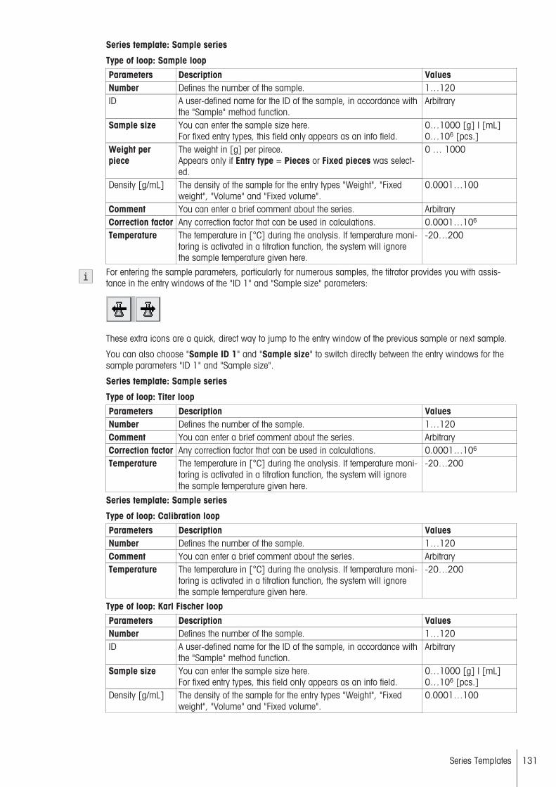
Series template: Sample series
Type of loop: Sample loopParameters Description ValuesNumber Defines the number of the sample. 1…120ID A user-defined name for the ID of the sample, in accordance with
the "Sample" method function.Arbitrary
Sample size You can enter the sample size here.For fixed entry types, this field only appears as an info field.
0…1000 [g] | [mL]0…106 [pcs.]
Weight perpiece
The weight in [g] per pirece.Appears only if Entry type = Pieces or Fixed pieces was selected.
0 … 1000
Density [g/mL] The density of the sample for the entry types "Weight", "Fixedweight", "Volume" and "Fixed volume".
0.0001…100
Comment You can enter a brief comment about the series. ArbitraryCorrection factor Any correction factor that can be used in calculations. 0.0001…106
Temperature The temperature in [°C] during the analysis. If temperature monitoring is activated in a titration function, the system will ignorethe sample temperature given here.
-20…200
For entering the sample parameters, particularly for numerous samples, the titrator provides you with assistance in the entry windows of the "ID 1" and "Sample size" parameters:
These extra icons are a quick, direct way to jump to the entry window of the previous sample or next sample.
You can also choose "Sample ID 1" and "Sample size" to switch directly between the entry windows for thesample parameters "ID 1" and "Sample size".
Series template: Sample series
Type of loop: Titer loopParameters Description ValuesNumber Defines the number of the sample. 1…120Comment You can enter a brief comment about the series. ArbitraryCorrection factor Any correction factor that can be used in calculations. 0.0001…106
Temperature The temperature in [°C] during the analysis. If temperature monitoring is activated in a titration function, the system will ignorethe sample temperature given here.
-20…200
Series template: Sample series
Type of loop: Calibration loopParameters Description ValuesNumber Defines the number of the sample. 1…120Comment You can enter a brief comment about the series. ArbitraryTemperature The temperature in [°C] during the analysis. If temperature moni
toring is activated in a titration function, the system will ignorethe sample temperature given here.
-20…200
Type of loop: Karl Fischer loopParameters Description ValuesNumber Defines the number of the sample. 1…120ID A user-defined name for the ID of the sample, in accordance with
the "Sample" method function.Arbitrary
Sample size You can enter the sample size here.For fixed entry types, this field only appears as an info field.
0…1000 [g] | [mL]0…106 [pcs.]
Density [g/mL] The density of the sample for the entry types "Weight", "Fixedweight", "Volume" and "Fixed volume".
0.0001…100
131Series Templates

Weight perpiece
The weight in [g] per pirece.Appears only if Entry type = Pieces or Fixed pieces was selected.
0 … 1000
Solvent weight Quantity of solvent in [g] in which the sample was extracted ordissolved.Only for method type = Ext. Extraction.
0...1000
Wt. extractedsample
Total weight of sample in [g] which was extracted or dissolved inthe solvent.Only for method type = Ext. Extraction.
0...1000
Comment You can enter a brief comment about the series. ArbitraryCorrection factor Any correction factor that can be used in calculations. 0.0001…106
Temperature The temperature in [°C] during the analysis. If temperature monitoring is activated in a titration function, the system will ignorethe sample temperature given here.
-20…200
Series template: Free sample series (only for single-sample loop methods)
Type of loop: Sample loopParameters Description ValuesNumber Defines the number of the sample. 1…120ID A user-defined name for the ID of the sample, in accordance with
the "Sample" method function.Arbitrary
Sample size You can enter the sample size here.For fixed entry types, this field only appears as an info field.
0…1000 [g] | [mL]0…106 [pcs.]
Weight perpiece
The weight in [g] per pirece.Appears only if Entry type = Pieces or Fixed pieces was selected.
0 … 1000
Density [g/mL] The density of the sample for the entry types "Weight", "Fixedweight", "Volume" and "Fixed volume".
0.0001…100
Comment You can enter a brief comment about the series. ArbitraryCorrection factor Any correction factor that can be used in calculations. 0.0001…106
Temperature The temperature in [°C] during the analysis. If temperature monitoring is activated in a titration function, the system will ignorethe sample temperature given here.
-20…200
When assigning a method at the start of the series template of a free sample series, the system ignores the following parameters (which are also defined in the "Sample" method function of the assigned method), and usethe ones defined here. If no values are entered here for these parameters, the values saved in the "Sample"method function will be used.
● ID 1● Sample size● Weight per piece● Density [g/mL]● Correction factor● Temperature [°C]
See also
● Sample (page 78)
132 Series Templates
8 Analysis Sequences
8.1 Starting an AnalysisAn analysis, whether it be a single or multiple determination, can be started on the titrator in several differentways:
1. By choosing one of the following options:• Start from the method editor• Start from "Home"• Start from the "Series" dialog• Titer to perform a titer determination in Setup (Navigation: Setup > Chemicals > Titrant >Titrant Parameters). (Not for titrations of type KF).
2. Using a user-specific shortcut or a direct shortcut from "Home".
When you create a shortcut by choosing AddToHome (see "Description of Functions > The User Interface >Shortcuts and Direct Shortcuts"), the following parameters are available:
Parameters Description ValuesDescription Any name for the shortcut. ArbitraryImmediate start The method, series, or manual operation can be started immedi
ately. This enables you to start the analysis without any interfering dialog.
Yes | No
Homescreenposition
You can select the free position for the shortcut on the Homescreen.
1…12
After you create the shortcut, it appears in the selected position in "Home", from where you can select it by tapping the touchscreen.When you start an analysis, whether by using a button or with a shortcut, the system always opens the Startanalysis dialog (see "Descripton of Functions > The User Interface > The Start Analysis Dialog"). The onlyexceptions are direct shortcuts ("Immediate start" = "Yes"), whose selected settings permit a direct start.
At the start of an analysis, you can still make changes to various settings in the Start analysis dialog. It istherefore possible, for example, to modify the sample size and define the number of samples to be determined.
If the analysis you want to start is a single determination, you can enter the sample size or sample ID directlyas a parameter in the Start analysis dialog.In general, the sample data can be entered for each individual sample using the Samples button in the Startanalysis dialog. In the Sample data dialog that opens when you choose this button, a list of the individualsamples is displayed.
In addition, the status is displayed for every sample (regardless of the loop type) in the Sample data dialog.The following status levels can be assigned to a sample:
● Idle: The sample is not yet running and the sample data can still be edited● Running: The sample is running but the sample data can still be edited● Active: The sample is running and the sample data can no longer be edited● Done: Done – the sample has run and concluded and the sample data can no longer be edited
If you select a sample, you can define the following sample data.
Parameters Description ValuesNumber Defines the number of the sample. 1…120ID 1 The ID for the first or only sample of an analysis. ArbitrarySample size You can enter the sample size here.
For fixed entry types, this field only appears as an info field.0…1000 [g] | [mL]0…106 [pcs.]
Weight perpiece
The weight in [g] per pirece.Appears only if Entry type = Pieces or Fixed pieces was selected.
0 … 1000
Density You can enter the sample's density, in [g/mL], here.Does not appear for the Entry type = Pieces and Fixed pieces.
0…100
133Analysis Sequences

ID 2…ID 3 The name defined here will be used as the default name for therespective sample on the sample loop.Only appears subject to the settings made for Number of IDs.
Arbitrary
Comment You can enter a brief comment about the series. ArbitraryCorrection factor Any correction factor that can be used in calculations. 0.0001…106
Temperature The temperature in [°C] during the analysis. If temperature monitoring is activated in a titration function, the system will ignorethe sample temperature given here.
-20…200
You can enter the following parameters in the Start analysis dialog, depending on the type of analysis to bestarted and the resources used:
Parameters Description ValuesType The type of analysis to be started. Method | SeriesWorkspace The workspace in which the sample series or analysis is to be
run. (In Workspaces A and B, tasks can be performed in parallelif they do not use the same resources. Tasks in each workspacewill be performed one after the other.) The workspace must bedefined for each sample series in the series sequence.
A | B
Number of standards
The number of standards to be analyzed with a method or series. 1…120
Number of samples
Defines the number of samples to be analyzed. 1…120
ID 1 The ID for the first or only sample of an analysis. ArbitrarySample size You can enter the sample size here.
For fixed entry types, this field only appears as an info field.0…1000 [g] | [mL]0…106 [pcs.]
Continuous run After each termination of the analysis (using series or methods)the analysis is automatically restarted (this is done until theprocess is canceled manually).
Yes | No
Start position < Defines the start position of the first sample on the samplechanger. CP means current position.Rondo only offers numbers in the range of 1...60.
1...60 | 1...303 | CP |CP+1 | CP+2
● All the parameters that can be edited in the Start analysis dialog or the sample data dialog will overwritethe settings defined in the method for the same parameters.
● All non-editable parameters that are displayed as an info field are only shown for orientation purposes andlist the settings from the method.
● If the sample size must be entered before the analysis but the user does not do so, the user will be requiredto enter it immediately before the start of the analysis.
8.2 Analysis Sequence StepsDuring the processing of an analysis, starting from the start of the analysis and sample addition through to theresults display, the titrator displays a range of dialog windows, some of which the user has to confirm in orderfor the analysis to continue. These dialog windows are used to ensure faultless processing, and also to providethe user with information.Depending on the required degree of automation for an analysis, it can, however, be useful and desirable todeactivate particular security questions or information dialogs to ensure that the sequence is processed withoutinterruption. Below are some process flow examples.For Karl Fischer titrations, the sequence of the analysis with the "KF stand" or with the "Stromboli" samplechanger is displayed. This includes the behavior during "Pretitration" and "Standby", the various functions during standby operation, and the associated behavior for results and statistics. Furthermore, the use of "Series"and "Open Series" and the behavior of the "Record" method function are also described.
For GT analyses, the sequence with the use of a manual or external titration stand and with the use of an automatic titration stand is displayed. In each case, you are told where the individual screens can be switched off inthe user interface.
134 Analysis Sequences

8.2.1 GT Analysis sequence
● Sample analysis sequence for an analysis with a titration stand of the "Manual stand" or "External stand"type:
<Start>
Dialog: Analysis start Can be switched off for the start via shortcut with the "Immediatestart" parameter during the creation or management of a shortcut.
<Start>
Check: Resources Can be switched off with the "Show required resources at start"parameter in the analysis sequence settings. (An error messagewill appear if the resources have already been allocated or aremissing.)
<OK>
Request: Sample size Appears when "Entry" = "Before" was selected in the "Sample"method function and the sample size = 0. Can be avoided byselected a "fixed" entry type.
<OK>
Add sample Can be switched off for the start via shortcut with the "Immediatestart" parameter during the creation or management of a shortcutfor the first sample.
<OK>
Dialog: Online
Request: Sample size For "Entry" = "Arbitary" parameter in the "Sample" method function.
<OK>
Results This can be switched on or off via the "Show results after analysis" parameter.(Navigation: Setup > Global settings > Analysis and resourcesbehavior > Analysis sequence setting).
135Analysis Sequences
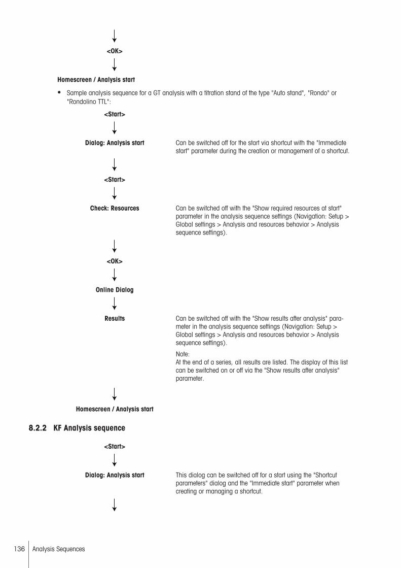
<OK>
Homescreen / Analysis start
● Sample analysis sequence for a GT analysis with a titration stand of the type "Auto stand", "Rondo" or"Rondolino TTL":
<Start>
Dialog: Analysis start Can be switched off for the start via shortcut with the "Immediatestart" parameter during the creation or management of a shortcut.
<Start>
Check: Resources Can be switched off with the "Show required resources at start"parameter in the analysis sequence settings (Navigation: Setup >Global settings > Analysis and resources behavior > Analysissequence settings).
<OK>
Online Dialog
Results Can be switched off with the "Show results after analysis" parameter in the analysis sequence settings (Navigation: Setup >Global settings > Analysis and resources behavior > Analysissequence settings).
Note:At the end of a series, all results are listed. The display of this listcan be switched on or off via the "Show results after analysis"parameter.
Homescreen / Analysis start
8.2.2 KF Analysis sequence
<Start>
Dialog: Analysis start This dialog can be switched off for a start using the "Shortcutparameters" dialog and the "Immediate start" parameter whencreating or managing a shortcut.
136 Analysis Sequences

<Start>
Check: Resources Can be switched off with the "Display required resources at start"parameter in the analysis sequence settings. (An error messagewill appear if the resources have already been allocated or aremissing.)
<OK>
Online dialog: Pretitration Selection of function options: Stop method, Samples (for changing samples and series data), End series, Save series data,Results, Axes,(see " Description of Functions > UserInterface > Online Dialog (page 14)").Automatic switch between Pretitration and Standby.
Online dialog: Standby Selection of function options: Start sample, Start concentration,Start blank (for external extraction, Samples (for changing samples and series data), Start drift determination, End series,Stop method, Save series data, Results*, Axes,Sample sizecalculation(see " Description of Functions > UserInterface > Online Dialog (page 14)").
<Start Sample> | <Start Concentration> |<Start Blank>
If the maximum number of samples, concentration determinations, and blank determinations has been reached and a measurement has been started, a message appears informing youthat a new series can be started.From the start of the first sample analysis in a predefined seriesto the processing of the last sample in the series, the concentration and blank determination functions cannot be selected in the"Standby" dialog.
If the voltage value of the measuring sensor is too low at the startof a sample, concentration, drift, or blank determination, whenthe user presses Start, they are informed that the system is overtitrated.
<OK>
Online dialog: Mix time Displays the time remaining and stirrer speed.
Online dialog: Titration (KF Vol) You have the following options during an analysis: Cancel thesample, concentration, drift, blank determination or the method,you can modify sample data, view results or measured values,save a series, or specify the axes of the measurement diagram.
Online dialog: Calculation
137Analysis Sequences

Online dialog: Standby
*During Standby or Pretitration mode, you can access the results of the current determination type (sample,concentration, blank determination). Here you can perform the following actions (see "Results (page 162)"):
● Recalculate (can only be changed for individual samples, and not for a whole loop)1
● Exclude samples1
● Perform outlier test1
● Results● Display statistics● Undo changes1For titrations using the "Stromboli" oven sample changer, these functions are only available at the start of theseries or in Standby mode and with Analysis start "manual".
Drift determinationThere are several different ways to determine the drift:
1. Using the "Drift determination" method function. Here you can enter the duration of determination. Themethod function can be inserted outside the loop (in determination per series) or inside the loop (in determination per sample) (only for KF methods of the type "Stromboli").
2. Spontaneous drift determinations: The drift can be determined from Standby mode of any KF method. Thedrift determined here is used if the "Source for drift" parameter in the "Titration stand" method function is setto "Setup".
3. Online drift determination: The drift that is constantly determined during standby operation is the current andcorrect drift value which is used in the calculations. To enable this, the "Source for drift" parameter in the"Titration stand" method function must be set to "Online" (see "Method functions: Titration stand(page 85)").
Concentration determinationThe concentration determination of the titrant can only be started spontaneously, and hence only from "Standby" mode.When a concentration determination is started, as with a sample determination, this opens an "Open series".After every determination, the mean value of the open concentration determination series is assigned to thetitrant in Setup. The open concentration determination series is ended by the start of a sample and blank determination (and vice versa). In general, the open series can be terminated by choosing End series, Stopmethod, or Reset. A spontaneous drift determination, however, does not terminate the series.
8.2.2.1 Series analyses with the "Stromboli" oven sample changer
Before starting a Stromboli method, the pump must be switched on and the set temperature specified. EveryStromboli method begins in the Start position (beaker is in the drift position). In this position, the pretitrations,the manual and automatic drift determinations, and the concentration determinations (only for KF Vol) are performed. The pretitration already takes place during the heating process.
The heating and the pump remain active in Standby mode. When a Stromboli method is active, the set temperature is controlled automatically.
After a series analysis is started via Start in the Standby dialog or because Analysis start = "automatic" is set,the series is processed automatically. After each sample is processed, the next sample is analyzed withoutprompting. To enable automatic analysis start, the following conditions must be fulfilled:
● The set temperature must be reached.● The online drift must be smaller than the maximum start drift.● The system must not be overtitrated.● The drift stability must be fulfilled.
Once the titration is complete, Standby mode is active until the end of the loop in the current sample beaker. Ifthe maximum start drift value is exceeded during this time, the sample changer returns to pretitration (drift position). The analysis is then continued automatically when the maximum start drift value is reached. If the lastsample in a loop has been processed and further loops still remain, the current position (sample or drift
138 Analysis Sequences
beaker) is maintained until the next sample is approached. The current drift is reviewed before the start of thenext sample. The following is a description of the behavior when particular actions are performed:
Analysis startEach analysis starts in position 1, immediately after the "Drift" position.
When using Stromboli, no positions can be controlled. The sample changer always moves forward by oneposition and performs an analysis or a blank determination in that position. Stromboli only returns to the "Drift"position to perform a drift determination.
Cancel methodThe method is terminated with no further action. The temperature control and the pump are switched off immediately. Stromboli returns to the "Drift" position.
Before actually stopping the process, the system displays a system message asking you to confirm the termination.
Drift determinationThe manual drift determination and the drift determination via method functions always take place in the "Drift"position. After manual drift determination, the sample changer remains in this position. In contrast, with driftdetermination using the method function, the sample changer moves to the next planned sample position.
Concentration determinationThe manual concentration determination is performed in the drift beaker. The heating and pump remain active.
Canceling the drift determination or concentration determinationBecause the drift and concentration determination is performed in the drift beaker, terminating the process hasno effect on the actions of the sample changer. The standby titration is started again.
Pressing ResetIf the Reset button is pressed while a KF analysis or manual operations are active, all Karl Fischer methods andmanual operations are terminated. For Stromboli, this means that the pumps are switched off, the titratorreturns to the resting position (via the drift beaker), and the heating is turned off. If a KF analysis (method orsample series) is terminated, the system continues with the pending analyses from the list. The sample data forthe terminated samples or sample series (such as weigh-ins, etc.) are still saved with the results.
8.2.2.2 External extraction
For the Karl Fischer "External extraction" method type, there is no automated sample analysis. Each sample ina series must be started individually from "Standby" mode.If the "Open series" parameter is set (see "Method Function: End of Sample (page 116)"), additional samplescan be added after a series has been processed. If "Open series" is not set, the series is completed after thespecified number of samples, and the method is stopped.
Manual blank value determination can be carried out from "Standby" mode..
8.2.2.3 Switching between determination types
You can determine statistics for sample, blank, and concentration determinations. If you switch between twodetermination types during an analysis, the determination series is ended. The system displays a message.You can then decide whether to choose Cancel to return to Standby mode, or choose OK to start the selecteddetermination.
When you end a determination series, the relevant results are not deleted. The results memory of this determination type is not deleted and refilled until a new determination type is started and if results are available. Theother determination types are not deleted and no new series entry is created in the results memory.For example: If you carry out multiple blank determinations and then carry out a concentration determination,the blank value statistics are terminated. The next time a blank determination is started, the memory for theblank determination is deleted and filled with new blank value data.
There are no mean values for drift determinations, each determination generates a new drift value that is transferred to Setup.
139Analysis Sequences

8.2.2.4 Analysis records
Analysis records are the printouts specified by the user in the "Records" method function (see "Method functions: Records (page 123)"). When a manual drift, concentration, and blank determination is created, the system creates a separate expression.
Printouts per seriesPrintouts "per series" are created if the user presses the End series button or if a series is terminated via Startconcentration or Start blank.
An open series does not count as finished until End series has been selected or a series is ended by choosingStart concentration or Start blank. After confirming the corresponding message, the "Record" method functioncan be used to print out all parts of the record defined for each series.
Printouts per sampleThe printouts are created for each sample when the "Records" method function is processed.
8.2.2.5 Replacing the titrant
The reagent in the beaker can be replaced when a certain number of samples is reached, if the solvent capacityis used up, or after a defined period of time (Intelligent Solvent Controlling). This causes a brief interruption inthe series sequence.
The titrant replacement procedure is semi-automatic, i.e. the user has to initiate the replacement.
140 Analysis Sequences
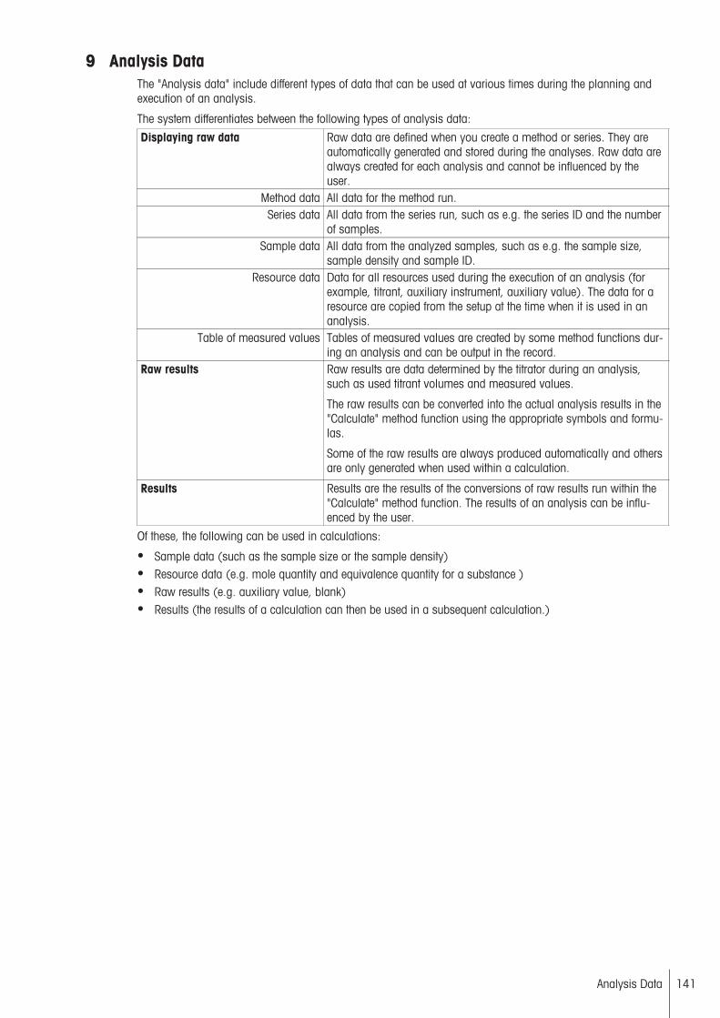
9 Analysis DataThe "Analysis data" include different types of data that can be used at various times during the planning andexecution of an analysis.
The system differentiates between the following types of analysis data:
Displaying raw data Raw data are defined when you create a method or series. They areautomatically generated and stored during the analyses. Raw data arealways created for each analysis and cannot be influenced by theuser.
Method data All data for the method run.Series data All data from the series run, such as e.g. the series ID and the number
of samples.Sample data All data from the analyzed samples, such as e.g. the sample size,
sample density and sample ID.Resource data Data for all resources used during the execution of an analysis (for
example, titrant, auxiliary instrument, auxiliary value). The data for aresource are copied from the setup at the time when it is used in ananalysis.
Table of measured values Tables of measured values are created by some method functions during an analysis and can be output in the record.
Raw results Raw results are data determined by the titrator during an analysis,such as used titrant volumes and measured values.
The raw results can be converted into the actual analysis results in the"Calculate" method function using the appropriate symbols and formulas.
Some of the raw results are always produced automatically and othersare only generated when used within a calculation.
Results Results are the results of the conversions of raw results run within the"Calculate" method function. The results of an analysis can be influenced by the user.
Of these, the following can be used in calculations:
● Sample data (such as the sample size or the sample density)● Resource data (e.g. mole quantity and equivalence quantity for a substance )● Raw results (e.g. auxiliary value, blank)● Results (the results of a calculation can then be used in a subsequent calculation.)
141Analysis Data

10 Titrator Evaluation ProcedureThe identification of equivalence point candidates within a defined recognition range can be done using four different evaluation methods:
● Standard● Minimum / Maximum● Segmented● Asymmetric
Which method you use for the evaluation will depend on the type of titration or the form of the resulting titrationcurve. The procedure to be used is defined in the "Evaluation and recognition" method subfunction of the "Titration (EQP)" and "Titration (two-phase)" method functions.
10.1 Standard Evaluation ProcedureThe titrator's standard evaluation procedure is based on the chemical model of a classic acid-base titration. Inthis model, the equivalence point of such a titration will be at the point of inflection of the S-shaped titrationcurve and the curve will be symmetrical with regard to this inflection point.
E
V
(1)
For the recognition of an inflection point using the standard procedure, the titrator will always look at one groupof measured values (a "measured value window"). It willexamine whether an inflection point is detectable for thatgroup of measured values. This window will then be shifted along the curve by one measured value and reexamined for points of inflection. The system repeats this procedure until it detects no inflection point twice in a row. Itthen uses the inflection points found to define the mostsuitable one as the final inflection point of the titration.
(1) Inflection point
These criteria can be defined in the "Evaluation and recognition" subfunction of the "Titration EQP" and "Titration(two-phase)" method functions.
The standard evaluation procedure initially only identifies points of inflection. Criteria defined by the user in themethod can influence whether and when an inflection point is to be registered as an EQP candidate.
If so defined in the method, the following criteria will have to be fulfilled:
● The inflection point must lie within a recognition range.● It must be above a threshold (refers to the first derivative).● The titration curve must demonstrate a specified tendency in the area of the inflection point.
EQPs are only detected in the range of the measured curve which is the specified by the "Tendency" parameter(Positive, Negativ), refer to method function "Titration (EQP): Evaluation and Recognition".
If these criteria are fulfilled, the inflection point becomes an EQP candidate.The additional EQP criteria can now be used to influence which EQP candidates are ultimately recognized asequivalence points.For the standard evaluation, the additional EQP criteria "Last EQP" and "Steepest jump" are available. They canbe selected individually for each defined recognition range.
See also
● Titration method function (page 158)● Titration method function (page 158)
10.2 Minimum / MaximumThe result of this evaluation is the calculated minimum (maximum) of the measured titration points. The classicexample of a titration curve with a minimum is the photometrically indexed surfactant determination.
142 Titrator Evaluation Procedure

E
V
The minimum (maximum) is calculated using a polynomial approximation of the titration curve in the range of theminimum (maximum). The equivalence point recognitionis done directly from the titration curve data.
10.3 Segmented EvaluationVarious indication methods (including photometry, conductometry, and amperometry) generate titration curveswith linear or approximately linear sections (segmented curves). The titrator uses individual procedures to evaluate these curves. For a precise determination of the equivalence point, it is very important that these curveshave both linear segments and a clear bend.
V
∆E/ ∆V
V
V
E
∆2E/ ∆V 2
Titration curve
The titration curve contains two more less linear segmentsand a bend between these two segments. The evaluationof segmented curves is generally done with the aid of thestandard procedure for S-shaped curves, with the systemusing as its evaluation basis not the titration curve's measured points but the data calculated from them in the firstderivative.
1. Derivative
The first derivative of a segmented curve is the first todemonstrate the typical S shape. Its inflection point is thetitration's equivalence point.
2. Derivative
The threshold references the second derivative of the titration curve. In other words, the equivalence point for adefined threshold must be above this threshold number.
EQPs are only detected in the range of the measured curvewhich is the specified by the "Tendency" parameter (Positive, Negativ), refer to method function "Titration (EQP):Evaluation and Recognition". Within the segmented procedure the tendency refers to the 1. derivative.
10.4 AsymmetricFor markedly asymmetrical curves, the standard procedure can result in a systematic error. The differencebetween the true equivalence point and the point of inflection can be greater than the normally achievable precision. For these cases, the titrator uses an evaluation that uses the Tubbs method.
This empirical approximation method is a procedure for the evaluation of asymmetrical, analog-registered titration curves. It can also be used for digitally recorded titration curves. The Tubbs procedure result will be closerto the true equivalence point for some asymmetrical curves than the inflection point.
This evaluation procedure is based on the following considerations:
143Titrator Evaluation Procedure

E
V
M
M
1
2
EQP
Each of the two branches of the titration curve will have awritable osculating circle with a minimal radius. The relationship between the two radii is determined by the curve'sasymmetry. The intersection of the connecting linesbetween the circle center points M1 and M2 and the titration curve produces the desired equivalence point. Theoretical calculations show that the true equivalence point forasymmetrical titration curves will always lie between theinflection point and the branch of the titration curve withthe greater degree of curvature (i.e. the smaller osculatingcircle).
The titrator uses a hyperbola to approximate those parts of the titration curve located in the area of the greatestcurvature. For each approximated hyperbola, the system determines the peak (the point with the greatest curvature). The center points of the assigned smallest osculating circles are the focal points of both hyperbolas. Theintersection of the connection lines from the two focal points and the titration curve produces the desired equivalence point, as shown above.
The evaluation requires at least six measured values in the area of the greatest curvature before and after thetitration curve's inflection point. If the course of the titration curve does not permit the inclusion of the osculatingcircles, the titrator will use the standard procedure to calculate the equivalence point. You will be notified of thisin the record of the "raw results".
EQPs are only detected in the range of the measured curve which is the specified by the "Tendency" parameter(Positive, Negativ), refer to method function "Titration (EQP): Evaluation and Recognition".
144 Titrator Evaluation Procedure

11 Evaluate and calculate
11.1 Indexing of method functionsThe method functions Titration (EP, EQP, 2-phase, LearnEQP), Stating, Measure (normal), Measure (MVT),Dispense, and Dispense (controlled) provide their own raw results within a method.These raw results are saved by the titrator in the order in which the generating method functions are processedwithin the method. To ensure that any time these method functions are used more than once the raw resultscan still be given a unique assignment to their individual method functions, they are divided into four groups:
● Group 1 (all titrations): Method function Titration (EP, EQP, two-phase, Lern EQP)● Group 2 (Stating): Method function Stating (normal)● Group 3 (all measurements): Method functions Measure (normal) and Measure (MVT)● Group 4 (all dispenses): Method function Dispense (normal) and Dispense (controlled)
If method functions from a group are used multiple times within a method, they are given indexes (beyond theloop limits). This group index allows unique referencing of the raw results during calculations.
If the structure of a method is changed, the group indices are automatically updated, guaranteeing the serialnumbering at all times.
● Make sure your calculations take this into consideration!
Calculations can be used independently of the method functions that generated the results. For the results, wesuggest using the IDs R1...Rn, following the sequence of the calculations in the method.
ExampleMethod function Group index ResultTitleSample
Titration standStir
Titration (EQP) 1Titration (EP) 2
Dispense 1Titration (EQP) 3
Calculation R1Calculation R2Calculation R3
End of sampleSample
Titration standDispense 2
Stating 1Titration (EP) 4
Titration (EQP) 5Calculation R4
End of sampleCalculation R5
For KF titrations (multiple loops are permitted for the Stromboli method type)Method function Group index ResultTitleSample (KF)
Titration stand (Stromboli)Mix time
Titration (KF Vol) 1Calculation R1
145Evaluate and calculate

Method function Group index ResultCalculation R2Calculation R3
End of sampleSample (KF)
Titration standMix time
Titration (KF Vol) 3Calculation R4
End of sampleCalculation R5
The group index "1" can be omitted because when a group index is missing, the system automatically assignsthe group index "1".
11.2 FormulasCalculation formulas can be used in the "Calculate" and "Condition" method functions. Some parameters withinmethod functions can also be defined in the form of formulas.
Formulas within the "Calculation" method functionOne typical example for a formula within the "Calculation" method function would be the expression R=VEQ inthe "Formula" parameter. In this case, the consumed volume of titrant up to the point at which the end point isreached is assigned to R. All the symbols can be used for analysis data in relations like this. The analysis datato be used must be generated by the method before the "Calculate" method function.
Formulas for entering values for parametersFormulas can also be used to specify the values for some parameters. For example, you can enter the stirringtime in a "Stir" method function in the form of a formula. The result of the formula will then be copied over as anondimensional value in the unit of the parameter in question.
ConditionsA condition is a formula whose result comes in the form of "true" or "false". Conditions can be used in variousmethod functions in the "Condition" parameter or subfunction. Depending on the condition's result, the methodfunction in question will be executed (condition true) or not executed (condition false).
● Auxiliary values and blanks defined in the setup can generally be used in formulas in the same manner assymbols. The general form for an auxiliary value is: H[Name] (as defined in the setup).
● Likewise, results from other "Calculation" method functions can be referenced in the "Calculation" methodfunction. (E.g. R3=R2+R1)(What is important in this case is to make sure that the results used must already be in existence at thetime they are to be used!)
11.2.1 Using analysis data in formulas
All analysis data that can be accessed via a symbol can be used in calculation formulas (see "Naming Conventions for Using Analysis Data in Calculations (page 150)").
All analysis data must be generated in the method before the point at which they will be used in a calculationformula. For some analysis data, this could be as checked early as during the validation in the processing of amethod. For others, whether or not the data are available at the time in question may not be decided until theexecution of the method. If the analysis data is not available at the time of the calculation, the result of the calculation formula will be "NaN" ("Not a number").
The formula must be assigned to a result (Rx) in the "Formula" parameter in the "Calculate" method function.
Analysis data for which symbols have been defined can be used in the most general cases in the following format (the separators ’_’ are only used for clarification purposes here; they are not used in the formulas):
146 Evaluate and calculate

Basic symbol plus symbol extension_group ID_symbol index_unit(x,y)_[group index]
Shortcuts● Instead of using VEQ and QEQ, you can also use the corresponding short forms (V and Q) in the formulas.● If you leave out the symbol index of a symbol, Symbol Index 1 will be used.
Example: VEQ stands for VEQ1● If you leave out the group index of a symbol, Group Index 1 will be used.
Example: VEQ1 stands for VEQ1[1]
All three rules can also be combined, for example:
Q stands for QEQ1[1]
Assignments in the form X(condition)Using the "Calculate" method function within a loop makes it possible to make assignments containing a condition.
Conditional assignments of this type can be made using the symbols QEQ, VEQ and EEQ and indexed usingthe group index.
Use of the logical operators AND and OR is not permitted within conditional assignments. Likewise, you cannotuse the mathematical operators (+, -, * and /) within the parenthetical expression.
Explanation ExamplesBasic symbol andsymbol extension
Taken together, they serve as anidentifier for the analysis data.
VEQ identifies the equivalence/end point of atitration.
GroupID Defines the group of method functions (Ti, Me, Di, or St) to which themethod function used to create theanalysis data belongs.
SLOPESt designates the slope of a sensor usedby a stating method function.
Symbol index Specifies precisely which analysisdata are meant if one method function generates analysis data multipletimes using the same symbol.
If multiple titrants are used in onemethod function, so the titer andnominal concentration will be usedmultiple times per generating methodfunction. In this case, the index canbe used to define the titrant data tobe used in a calculation.
VEQ2 designates the consumed volume at the2nd equivalence point of an EQP titration.
c2 references the nominal concentration of the2nd titrant
TITER2 references the titer of the second titrantused.
Unit(x) / Unit(x,y) Unit(x) specifies which time ("t"),potential ("E") or conversion ("CON")the analysis data should reference.
Unit(x,y) specifies the time intervalthe analysis data should reference.
VE(7) designates the titrant volume required toreach a pH of 7 (for the pH unit).
CVt(1.5) designates the mean stating use perminute in the time interval between one and fiveminutes.
Group index Specifies which method functionwithin a method function group generates the analysis data.
ESTSt[3] is the designation of the start potentialof the 3rd method function from the methodfunction group "Stating".
Shortcuts
General examples for the use of a formula in the "Calculate" method function:R1=VStt(1.5)[2]
This example provides the volume (basic symbol = V) consumed during stating until the time of 1.5 (1 minute,30 seconds) (unit(x) = time t(x)) as a result for the second method function (group index = 2) from the Stating group (group ID = St).
R2=SLOPEMeE(7)
This example provides the slope (basic symbol = SLOPE) of the sensor used at pH 7 (unit(x) = potential E(x))as a result for the first method function (group index = 1, can be omitted) from the Measure group (group ID =Me).
147Evaluate and calculate
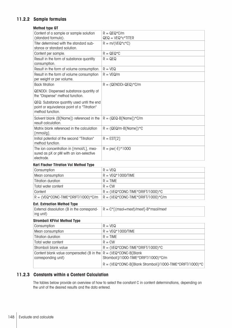
11.2.2 Sample formulas
Method type GTContent of a sample or sample solution(standard formula).
R = QEQ*C/mQEQ = VEQ*c*TITER
Titer determined with the standard substance or standard solution.
R = m/(VEQ*c*C)
Content per sample. R = QEQ*CResult in the form of substance quantityconsumption.
R = QEQ
Result in the form of volume consumption. R = VEQResult in the form of volume consumptionper weight or per volume.
R = VEQ/m
Back titration
QENDDi: Dispensed substance quantity ofthe "Dispense" method function.
QEQ: Substance quantity used until the endpoint or equivalence point of a "Titration"method function.
R = (QENDDi-QEQ)*C/m
Solvent blank (B[Name]) referenced in theresult calculation.
R = (QEQ-B[Name])*C/m
Matrix blank referenced in the calculation[mmol/g].
R = (QEQ/m-B[Name])*C
Initial potential of the second "Titration"method function.
R = EST[2]
The ion concentration in [mmol/L], measured as pX or pM with an ion-selectiveelectrode.
R = pw(-E)*1000
Karl Fischer Titration Vol Method TypeConsumption R = VEQMean consumption R = VEQ*1000/TIMETitration duration R = TIMETotal water content R = CWContent R = (VEQ*CONC-TIME*DRIFT/1000)*CR = (VEQ*CONC-TIME*DRIFT/1000)*C/m R = (VEQ*CONC-TIME*DRIFT/1000)*C/m
Ext. Extraction Method TypeExternal dissolution (B in the corresponding unit)
R = C*[(msol+mext)/mext]-B*msol/mext
Stromboli KFVol Method TypeConsumption R = VEQMean consumption R = VEQ*1000/TIMETitration duration R = TIMETotal water content R = CWStromboli blank value R = (VEQ*CONC-TIME*DRIFT/1000)*CContent blank value compensated (B in thecorresponding unit)
R = (VEQ*CONC-B[BlankStromboli]/1000-TIME*DRIFT/1000)*C/m
R = (VEQ*CONC-B[Blank Stromboli]/1000-TIME*DRIFT/1000)*C
11.2.3 Constants within a Content Calculation
The tables below provide an overview of how to select the constant C in content determinations, depending onthe unit of the desired results and the data entered.
148 Evaluate and calculate

Desired indication of the result:
content per gram of the sample
Input of the sample in [g]: R =QEQ*C/m
Input of the sample in [mL]: R =QEQ*C/(m*d)
Input of the sample in [St.]: R =QEQ*C/(m*wp)
Desired indication of the result:
Content per milliliter of thesample
Input of the sample in [mL]: R =QEQ*C/m
Input of the sample in [g]: R =QEQ*C/(m/d)
Desired indication of the result:
Content per item of the sample
Input of the sample in [St.]: R =QEQ*C/m
Constant Unit Constant Unit Constant UnitC = 1/z [mmol/g],
[mol/kg]C = 1/z [mmol/mL],
[mol/L]C = 1/z [mmol/pc.]
C = M/z [mg/g], [g/kg] C = M/z [mg/mL], [g/L] C = M/z [mg/pc.]C = 1 [meq/g],
[eq/kg]C = 1 [meq/mL],
[eq/L]C = 1 [meq/pc.]
C = 1000/z [mmol/kg],[µmol/g]
C = 1000/z [mmol/L],[µmol/mL]
C = 1000/z [µmol/pc.]
C = 1000 [meq/kg],[µeq/g]
C = 1000 [meq/L],[µeq/mL]
C = 1000 [µeq/pc.]
C = M*1000/z [ppm],[mg/kg], [µg/g]
C = M*1000/z [mg/L],[µg/mL]
C = M*1000/z [µg/pc.]
C = M -- C = M -- C = M --C = M*1000 -- C = M*1000 -- C = M*1000 --C = M/(10*z) [%] (w/w) C = M/(10*z) [g/100mL],
[%] (w/v)C = M/(10*z) --
C = 56.1 [mgKOH/g](TAN, TBN)
C = 56.1 -- C = 56.1 --
Calculation formulas for the titer determination
Standard type: fixed (input type = weight)
R = m/(VEQ*c*C) C = M/(10*p*z)
Standard type: liquid (entry type = volume)
R = m/(VEQ*c*C) C = 1/(cst*z)
Standard type: liquid (input type = weight)
R = m/(VEQ*c*C)C = d/(cst*z)
The data shown above applies similarly for more complex content determinations as well:
Back titration content: R = (QENDDi-Q)*C/m
Content with blank: R = (QEQ-B[Name])*C/m
Stating content: R = QENDSt*C/m
11.2.4 Mathematical functions and operators
The following mathematical functions and operators can be used in formulas:
Functions Comparison operatorsLogarithm to the base 10 lg(x) equal to =Logarithm to the base e Ln(x) larger than > Exponential to base 10 pw(x) or
scientific notationlarger than or equal to > =
Exponential to base e ex(x) smaller than <Square sq(x) smaller than or equal to <=Square root sr(x) x in the range of ... < x < ...
not equal to < >
149Evaluate and calculate
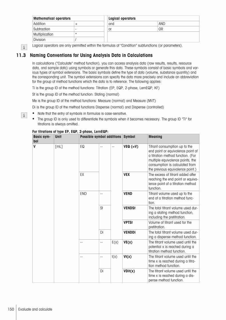
Mathematical operators Logical operatorsAddition + and ANDSubtraction - or ORMultiplication *Division /
Logical operators are only permitted within the formulas of "Condition" subfunctions (or parameters).
11.3 Naming Conventions for Using Analysis Data in CalculationsIn calculations ("Calculate" method function), you can access analysis data (raw results, results, resourcedata, and sample data) using symbols or generate this data. These symbols consist of basic symbols and various types of symbol extensions. The basic symbols define the type of data (volume, substance quantity) andthe corresponding unit. The symbol extensions can specify the data more precisely and include an abbreviationfor the group of method functions which the data is to reference. The following applies:
Ti is the group ID of the method functions: Titration (EP, EQP, 2-phase, LernEQP, KF)
St is the group ID of the method function: Stating (normal)
Me is the group ID of the method functions: Measure (normal) and Measure (MVT)
Di is the group ID of the method functions Dispense (normal) and Dispense (controlled)
● Note that the entry of symbols in formulas is case-sensitive.● The group ID is only used to differentiate the symbols when it becomes necessary. The group ID "Ti" for
titrations is always omitted.
For titrations of type EP, EQP, 2-phase, LernEQP:Basic symbol
Unit Possible symbol additions Symbol Meaning
EQ VEQ (=V) Titrant consumption up to theend point or equivalence point ofa titration method function. (Formultiple equivalence points, theconsumption is calculated fromthe previous equivalence point.)
EX
--
VEX The excess of titrant added afterreaching the end point or equivalence point of a titration methodfunction.
-- VEND Titrant volume used up to theend of a titration method function.
VENDSt The total titrant volume used during a stating method function,including the pretitration.
St
VPTSt Volume of titrant used for thepretitration.
END
Di
--
VENDDi The total titrant volume used during a dispense method function.
-- -- E(x) VE(x) The titrant volume used until thepotential x is reached during atitration method function.
-- Vt(x) The titrant volume used until thetime x is reached during a titration method function.
V [mL]
--
Di
t(x)
VDit(x) The titrant volume used until thetime x is reached during a dispense method function.
150 Evaluate and calculate

Basic symbol
Unit Possible symbol additions Symbol Meaning
EQ QEQ (=Q) Substance quantity used up tothe end point or equivalencepoint of a titration method function.
EX
--
QEX Excess substance quantity titrated in after reaching the end pointor equivalence point of a titrationmethod function.
-- QEND The total substance quantityused up to the end of a titrationmethod function.
QENDSt The total substance quantityused during a stating methodfunction.
St
QPTSt Substance quantity of titrant usedfor the pretitration.
END
Di
--
QENDDi The total substance quantityused during a dispense methodfunction.
-- -- E(x) QE(x) The substance quantity useduntil the potential x is reachedduring a titration method function.
-- Qt(x) The substance quantity useduntil the time x is reached duringa titration method function.
QStt(x) The substance quantity useduntil the time x is reached duringa stating method function.
Q [mmol]
--
Di
t(x)
QDit(x) The substance quantity useduntil the time x is reached duringa dispense method function.
-- t The time of a titration methodfunction.
St tSt The time of a stating methodfunction.
Di tDi The time of a dispense methodfunction.
--
Me tMe The time of a measurementmethod function.
USE --
--
tUSE The time of an analysis of asample from the start of the loopto the usage of the symbol in themethod function "Calculate"(cannot be used for conditions.)
t [min]
-- CON(x)
tCON(x) Specifies the time for a statingmethod function until the conversion of x% of the titrant used forstating. (Relative to 100% reaction conversion at the end of astating method function.)
151Evaluate and calculate
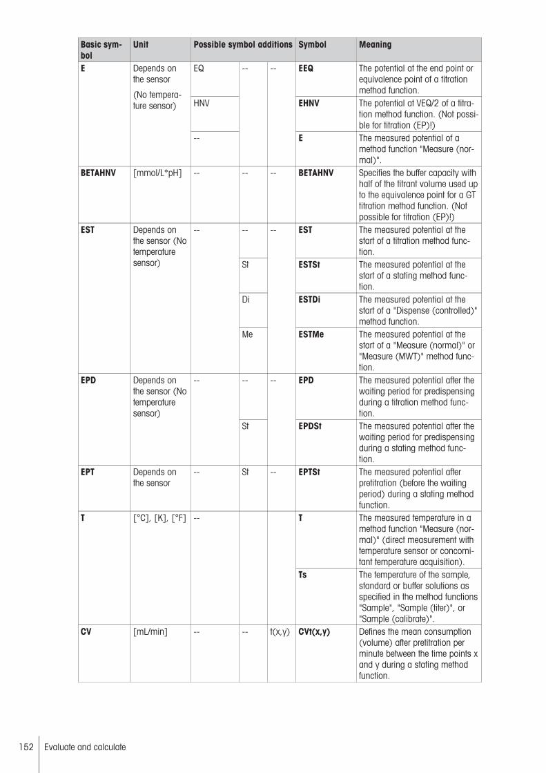
Basic symbol
Unit Possible symbol additions Symbol Meaning
EQ EEQ The potential at the end point orequivalence point of a titrationmethod function.
HNV EHNV The potential at VEQ/2 of a titration method function. (Not possible for titration (EP)!)
E Depends onthe sensor
(No temperature sensor)
--
-- --
E The measured potential of amethod function "Measure (normal)".
BETAHNV [mmol/L*pH] -- -- -- BETAHNV Specifies the buffer capacity withhalf of the titrant volume used upto the equivalence point for a GTtitration method function. (Notpossible for titration (EP)!)
-- EST The measured potential at thestart of a titration method function.
St ESTSt The measured potential at thestart of a stating method function.
Di ESTDi The measured potential at thestart of a "Dispense (controlled)"method function.
EST Depends onthe sensor (Notemperaturesensor)
--
Me
--
ESTMe The measured potential at thestart of a "Measure (normal)" or"Measure (MWT)" method function.
-- EPD The measured potential after thewaiting period for predispensingduring a titration method function.
EPD Depends onthe sensor (Notemperaturesensor)
--
St
--
EPDSt The measured potential after thewaiting period for predispensingduring a stating method function.
EPT Depends onthe sensor
-- St -- EPTSt The measured potential afterpretitration (before the waitingperiod) during a stating methodfunction.
T The measured temperature in amethod function "Measure (normal)" (direct measurement withtemperature sensor or concomitant temperature acquisition).
T [°C], [K], [°F] --
Ts The temperature of the sample,standard or buffer solutions asspecified in the method functions"Sample", "Sample (titer)", or"Sample (calibrate)".
CV [mL/min] -- -- t(x,y) CVt(x,y) Defines the mean consumption(volume) after pretitration perminute between the time points xand y during a stating methodfunction.
152 Evaluate and calculate

Basic symbol
Unit Possible symbol additions Symbol Meaning
CQ [mmol/min] -- -- t(x,y) CQt(x,y) Defines the mean consumption(substance quantity) per minutebetween the time points x and yduring a stating method function.
CON [%] -- t(x) CONt(x) Specifies the reaction conversionat the time x in percent. (Relativeto 100% reaction conversion atthe end of a stating method function.)
CORR -- -- -- t(x,y) CORRt(x,y) CVt(x,y) and CQt(x,y) are determined using the linear regression of the measured valuesbetween x and y. CORR is thecoefficient of correlation of thislinear regression (volume versustime) and provides a standardfor its quality.
-- TITER The titer value for a titrant usedin a titration method function.
St TITERSt The titer value for a titrant usedin a stating method function.
TITER -- --
Di
--
TITERDi The titer value for a titrant usedin a dispense method function.
-- c Specifies the nominal concentration of a titrant used for a titration method function.
St cSt Specifies the nominal concentration of a titrant used for a statingmethod function.
c [mol/L] --
Di
--
cDi Specifies the nominal concentration of a titrant used for a dispense method function.
-- CELLC Specifies the cell constant of aconductivity sensor used for atitration method function.
CELLC [1/cm] --
Me
--
CELLCMe Specifies the cell constant of aconductivity sensor used formeasurement method functions.
153Evaluate and calculate

Basic symbol
Unit Possible symbol additions Symbol Meaning
-- SLOPE Specifies the slope of a pH or ISEsensor or a Phototrode for atitration method function.
St SLOPESt Specifies the slope of a pH sensor for a stating method function.
Di SLOPEDi Specifies the slope of a pH sensor for a "Dispense (controlled)"method function .
Me SLOPEMe Specifies the slope of a pH or ISEsensor or a Phototrode for ameasurement method function.
--
Cal
--
SLOPECalx Reports the slope for the segment x after a Calibration.
-- SLOPEE(x) Specifies the slope of a pH or ISEsensor or a Phototrode at apotential of x for a titrationmethod function.
St SLOPEStE(x) Specifies the slope of a pH sensor at a potential of x for a stating method function.
Di SLOPEDiE(x) Specifies the slope of a pH sensor at a potential of x for a "Dispense (controlled)" method function .
--
Me
E(x)
SLOPEMeE(x) Specifies the slope of a pH or ISEsensor or a Phototrode at apotential of x for a measurementmethod function.
-- SLOPEMean Specifies the mean slope of a pHor ISE sensor or a Phototrode fora titration method function.
St SLOPEMeanSt Specifies the mean slope of a pHsensor for a stating method function.
Di SLOPEMeanDi Specifies the mean slope of a pHsensor for a "Dispense (controlled)" method function .
SLOPE Depends onthe sensor
Mean
Me SLOPEMeanMe
Specifies the mean slope of a pHor ISE sensor or a Phototrode fora measurement method function.
154 Evaluate and calculate

Basic symbol
Unit Possible symbol additions Symbol Meaning
-- ZERO Specifies the zero point of a pH,ISE or temperature sensor or aPhototrode for a titration methodfunction.
St ZEROSt Specifies the zero point of a pHsensor for a stating method function.
Di ZERODi Specifies the zero point of a pHsensor for a "Dispense (controlled)" method function .
Me ZEROMe Specifies the zero point of a pH,ISE or temperature sensor or aPhototrode for a measurementmethod function.
--
Cal
--
ZEROCalx Reports the zero point for thesegment x after a Calibration.
-- ZEROE(x) Specifies the zero point of a pH,ISE or temperature sensor or aPhototrode at a potential of x fora titration method function.
St ZEROStE(x) Specifies the zero point of a pHsensor at a potential of x for astating method function.
Di ZERODiE(x) Specifies the zero point of a pHsensor at a potential of x for a"Dispense (controlled)" methodfunction .
--
Me
E(x)
ZEROMeE(x) Specifies the zero point of a pH,ISE or temperature sensor or aPhototrode at a potential of x fora measurement method function.
-- ZEROMean Specifies the mean zero point ofa pH or ISE sensor for a titrationmethod function.
St ZEROMeanSt Specifies the mean zero point ofa pH sensor for a stating methodfunction.
Di ZEROMeanDi Specifies the mean zero point ofa pH sensor for a "Dispense(controlled)" method function .
ZERO Depends onthe sensor
Mean
Me
--
ZEROMeanMe Specifies the mean zero point ofa pH or ISE sensor for a measurement method function.
M [g/mol] -- -- -- M The molecular weight of a substance. (As defined in the setup.)
z -- -- -- -- z The equivalent number of a substance. (As defined in the setup.)
B [µg]
[mmol]
-- -- -- B[Name] A blank.
H -- -- -- -- H[Name] An auxiliary value.m [mL]
[g]
[pcs]
-- -- -- m The sample size.
155Evaluate and calculate

Basic symbol
Unit Possible symbol additions Symbol Meaning
d [g/mL] -- -- -- d The density of a sample or astandard.
wp [g/pcs] -- -- -- wp The weight per item (can bechanged under "Sample").
f -- -- -- -- f A correction factor (as defined inthe "Sample" method function).
p [%] -- -- -- p The purity of a solid titer standard.
cSt [mol/L] -- -- -- cSt The concentration of a liquid titerstandard.
Rx Arbitrary -- -- -- Rx A result x.C -- -- -- -- C A constant that uniquely belongs
to the result Rx. It cannot beused in this form for the calculations of other results.
Mean Arbitrary Rx -- -- Mean[Rx] The mean value of a result Rx.s Arbitrary Rx -- -- s[Rx] The standard deviation of a
result Rxsrel [%] Rx -- -- srel[Rx] The relative standard deviation of
the result Rx.-- n The sample number.TOT nTOT Total number of samples in the
loop.
n --
EQ
-- --
neq The number of equivalent pointsfor the Titration (EQP, Lern EQPor two-phase) method function.
AuxInst -- -- -- -- AuxInst Result of the method function"Auxiliary instrument" from thesequence of the external auxiliary instrument.
Rx[yy] Rx[yy] Uses the value in the ResultBuffer list for the correspondingsample for Result x from themethod with ID yy.
All the symbols listed in the above table can be used in calculations within a loop.
The following symbols can be used in calculations outside loops:
M z B[Name] H[Name]C Titer SLOPE ZEROCELLC SLOPEE(x) ZEROE(x) SLOPEMeanZEROMean Mean[Rx] s[Rx] srel[Rx]SLOPECalx ZEROCalxVENDDi, QENDDi and tDi(within a method function Dispense outside a loop)
Results (symbol "R") that are generated outside loops can also be used in calculations outside loops.
For titrations of type KF Vol
Basic symbol Unit Possiblesymboladditions
Symbol Meaning
V [mL] EQ VEQ (=V) Titrant consumed up to the end point of thetitration method function.
VPOST [mL] -- VPOST Volume of titrant for post-consumptionmeasurement.
156 Evaluate and calculate

TIME [min:s] -- TIME Duration of a sample analysis from theend of Standby until the end of the methodfunction Titration (KF Vol)
t [min:s] -- t Duration of a sample analysis.E [mV] EQ EEQ Potential at the end point of the titration
method function.EST [mV] -- EST Measured potential at the start of the titra
tion method function.DRIFT [µg(H2O)/min] -- DRIFT Consumption (mass) per minute for the
titration method function (water quantityper time unit that penetrates the titrationstand).
DRIFTV [µL/min] -- DRIFTV Volume of titrant consumption per minutefor the drift determination.
CW [µg] -- CW Volume of water titrated up to EP (withoutdrift or blank value correction).
CWPOST [µg] -- CWPOST Titrated volume of water during a post-consumption measurement (without drift orblank value correction).
CWPOSTMean [µg/min] -- CWPOSTMean Determined quantity of titrated water perunit of time during the post-consumptionmeasurement (without drift or blank valuecorrection).
CONC [mg/mL] -- CONC Represents the actual titrant concentration.B Arbitrary for KF
stand, e.g. [%]and [ppm],[µg] for Stromboli
-- B[Name] A blank.
H arbitrary -- H[Name] Auxiliary value.[mL][g][pcs]
-- m The sample size.
[g] sol msol Solvent weight for titrations of type KF Ext.Extr. (External extraction).
m
[g] EXT mext Extracted sample quantity for titrations oftype KF Ext. Extr.
d [g/mL] -- d The density of a sample or a standard.wp [g/pcs] -- wp The weight per item (can be changed
under "Sample").f -- -- f A correction factor (as defined in the "Sam
ple" method function).CONT [mg/g]
[mg/mL]
[mg/pc]
[%]
[ppm]
-- CONT The concentration of a liquid KF standard.
Rx Arbitrary -- Rx A result x.C -- -- C A constant that uniquely belongs to the
result Rx. It cannot be used in this form forthe calculations of other results.
Mean Arbitrary Rx Mean[Rx] The mean value of a result Rx.s Arbitrary Rx s[Rx] The standard deviation of a result Rxsrel [%] Rx srel[Rx] The relative standard deviation of the result
Rx.n -- -- n The sample number.
157Evaluate and calculate

11.4 Explanatory examples
11.4.1 Titration method function
E [mV]
V [mL]
a
bEPD
EST
EPD
Predispensing
The following shows the various type of predispensing that can be used during a titration method:
a: Reference to a defined volume (or to the product of a factor and the sample size)b: Reference to a defined potential
EST Provides the potential at the start of the titration.EPD Provides the potential after dispensing and the waiting time.
E [mV]
V [mL]
EEQ1
EEQ2
EEQ3
EHNV2
EHNV3
VEQ1QEQ1
VEQ2QEQ2
VEQ3QEQ3
VEXQEX
1
2
3
nEQ = 3
EHNV1
VENDQEND
Q [mmol]
Sample EQP titration containing three equivalence points
The following shows the three (nEQ = 3) recognized equivalence points (1, 2 and 3).
VEQ1, VEQ2 and VEQ3 Provide the calculated volume used until each EQP.QEQ1, QEQ2 and QEQ3 Provide the calculated substance quantity used until each EQP.EEQ1, EEQ2 and EEQ3 Provide the potential at each EQP.EHNV1, EHNV2 and EHNV3 Provide the "half neutralization point" for each EQP.VEX and QEX Provide the excess volume titrated and the excess substance
quantity titrated.
158 Evaluate and calculate
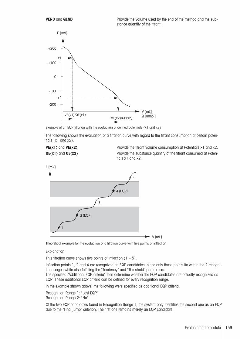
VEND and QEND Provide the volume used by the end of the method and the substance quantity of the titrant.
V [mL]
E [mV]
-200
-100
0
+100
+200
x1
x2
VE(x1)/QE(x1)VE(x2)/QE(x2)
Q [mmol]
Example of an EQP titration with the evaluation of defined potentials (x1 and x2)
The following shows the evaluation of a titration curve with regard to the titrant consumption at certain potentials (x1 and x2).
VE(x1) and VE(x2) Provide the titrant volume consumption at Potentials x1 and x2.QE(x1) and QE(x2) Provide the substance quantity of the titrant consumed at Poten
tials x1 and x2.
E [mV]
V [mL]
1
2 (EQP)
3
4 (EQP)
5
Theoretical example for the evaluation of a titration curve with five points of inflection
Explanation:
This titration curve shows five points of inflection (1 – 5).
Inflection points 1, 2 and 4 are recognized as EQP candidates, since only these points lie within the 2 recognition ranges while also fulfilling the "Tendency" and "Threshold" parameters.The specified "Additional EQP criteria" then determine whether the EQP candidates are actually recognized asEQP. These additional EQP criteria can be defined for every recognition range.
In the example shown above, the following were specified as additional EQP criteria:
Recognition Range 1: "Last EQP"Recognition Range 2: "No"
Of the two EQP candidates found in Recognition Range 1, the system only identifies the second one as an EQPdue to the "Final jump" criterion. The first one remains merely an EQP candidate.
159Evaluate and calculate

The termination criterion defined was that the titration should be terminated after the recognition of three EQPcandidates ("Termination after EQP" = "3"). In the above example the titration is terminated on identification ofthe 4th turning point (3rd EQP candidate).
11.4.2 Stating method function
V [mL] / Q [mmol]
t [s]
VENDSt / QENDSt
t1 t2
VStt(t2) / QStt(t2)
VStt(t1) / QStt(t1)
0
VPTSt / QPTSt
Stating example including evaluation at specified points in time (t1, t2) where 0 is the start of the Stat titration following thepretitration.
VENDSt, QENDSt Provide the entire volume consumed and the entire substance quantity consumed
VStt(t1) and VStt(t2) Provide the titrant volume consumed at Times t1 and t2QStt(t1) and QStt(t2) Provide the substance quantity consumed at Times t1 and t2VPTSt Volume used for pretitration: {mL}QPTSt Substance quantity of titrant used for pretitration: {mmol}
V [mL] / Q [mmol]
t [s]
0 t1 t2
VStt(t2) / QStt(t2)
VStt(t1) / QStt(t1)
VENDSt / QENDSt
tSt
0
VStt(tCON(100))
QStt(tCON(100))
Stating example including pretitration (gray area) and evaluation at specified points in time (t1, t2)
VENDSt, QENDSt Provide the entire volume used and the entire substance quantity used at theend of stating (including the pretitration)
VStt(t1) and QStt(t1) Provide the titrant volume consumption and the substance quantity consumption at Time t1 (not including pretitration)
VStt(t2) and QStt(t2) Provide the titrant volume consumption and the substance quantity consumption at Time t2 (not including pretitration) )
VStt(tCON(100))/QStt(tCON(100))
Provide the titrant volume consumption and the substance quantity consumption at the end of stating (not including pretitration)
160 Evaluate and calculate

CVt(t1,t2)
CQt(t1,t2)
t [s]
t2t1
∆V/ ∆t [mL/s]
Stating example including evaluation of the mean titrant consumption
The following is a stating example including the evaluation of the mean consumption between Times t1 and t2.CVt(t1,t2) and CQt(t1,t2) are determined using linear regression over the measured values between Times t1and t2. CORRt(t1,t2) specifies the coefficient of correlation of this linear regression.
CVt(t1,t2) Provides the mean titrant consumption between t1 and t2 in the form of volume pertime.
CQt(t1,t2) Provides the mean titrant consumption between t1 and t2 in the form of substancequantity per time.
161Evaluate and calculate

12 ResultsThe Results dialog can be accessed directly from Home using the relevant button.
● In the T50 and T70, the system only saves the results from the last analysis (series or individual sample).In the T90 you can use the "Select series" button to select the results from the last two analyses.
● When you start a new analysis, you will lose the results from the previous analysis.● You can see the results immediately after they are generated.
You can use the various buttons in the "Results" dialog to access different functions. You can, for example,
● view all results of the last analysis (in the T90, these are the results of the last two individual samples orseries).
● add a supplementary result calculation both within the loop (for all samples in the analysis), and outside aloop (once for the entire analysis).
● access results that are stored in the buffer (does not apply for Karl Fischer titration).● view statistics, perform an outlier test and if necessary, exclude samples from the statistics.● perform recalculations for results in which certain raw data (e.g. sample sizes) have to be adapted retro
spectively for a single sample or for all samples in a series.● perform a reevaluation for the method functions Titration (EQP) and Titration (2-phase) in which the criteria
for identification and evaluation of the equivalence point are retrospectively adapted.● view and print the status and the calculated results of each individual sample.
Results are retained until new results are generated by methods. The results of the "older" of the two sampleseries are replaced.In KF methods, the End series function can be used to generate a new result entry during the execution of amethod. After the series is finished, the original sample parameters are used, i.e. the changes made in the Startanalysis dialog or later are not taken into account. A new series is entered in the results.
In Karl Fischer (KF) titrations, the results are divided into the three determination types "Sample", "Concentration", and "Blank". All options for managing results only have an effect on the determinations of one particulardetermination type.While an analysis is running, only the current determination type is available.
If a determination type ("Sample", "Blank", or "Concentration") is started for a second time, existing data areoverwritten.
All the changes performed on the saved results can be reversed with the "Undo changes" button.
Changes to results are indicated by an asterisk in the record. Example: VEQ*.
12.1 Results proposal list for GTPredefined results for general titration (GT) are displayed here. Use the Results proposals button in the Addresult dialog to reach the results proposal lists.
When the user selects a result proposal from the list, the "Results", "Result unit", "Formula", and "Constant"parameters are automatically filled and cannot be changed (depends on titrator type).The proposal lists are filtered by method type and entry type. "Result" and "Result unit" define the formula withthe help of the entry type chosen in the "Sample" method function. If the entry type changes, the formula ismodified if the result type is "automatic" (if this is possible for the unit in question). If no formula exists for thenewly selected entry type, the system should detect this during method validation when the entry type is saved.
The formulas listed below are result proposals.
Result Unit Formula R = ConstantContent % Q*C/m M/(10*z)Content g/100mL Q*C*d/m M/(10*z)Content mg/g Q*C/(m*d) M/z)Content mL/g VEQ/m --Content mol/L Q*C/m 1/zContent ppm Q*C/m M*1000/zContent ppm Q*C/mM*1000/z
162 Results
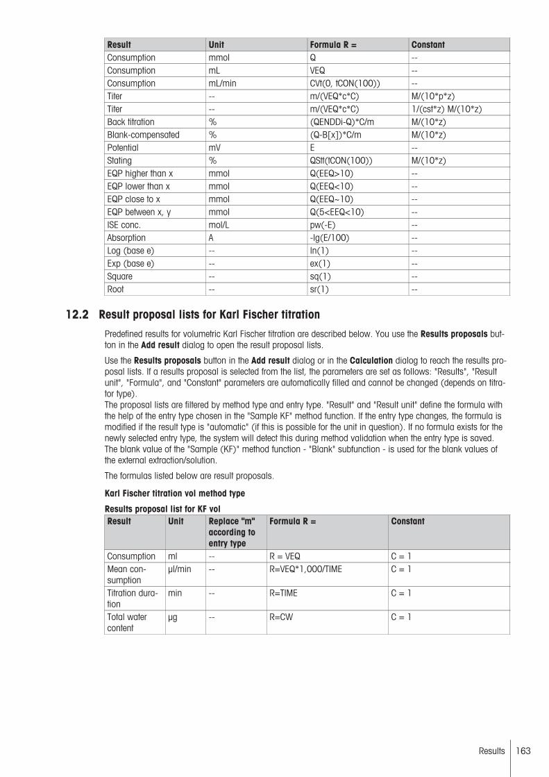
Result Unit Formula R = ConstantConsumption mmol Q --Consumption mL VEQ --Consumption mL/min CVt(0, tCON(100)) --Titer -- m/(VEQ*c*C) M/(10*p*z)Titer -- m/(VEQ*c*C) 1/(cst*z) M/(10*z)Back titration % (QENDDi-Q)*C/m M/(10*z)Blank-compensated % (Q-B[x])*C/m M/(10*z)Potential mV E --Stating % QStt(tCON(100)) M/(10*z)EQP higher than x mmol Q(EEQ>10) --EQP lower than x mmol Q(EEQ<10) --EQP close to x mmol Q(EEQ~10) --EQP between x, y mmol Q(5<EEQ<10) --ISE conc. mol/L pw(-E) --Absorption A -lg(E/100) --Log (base e) -- ln(1) --Exp (base e) -- ex(1) --Square -- sq(1) --Root -- sr(1) --
12.2 Result proposal lists for Karl Fischer titrationPredefined results for volumetric Karl Fischer titration are described below. You use the Results proposals button in the Add result dialog to open the result proposal lists.
Use the Results proposals button in the Add result dialog or in the Calculation dialog to reach the results proposal lists. If a results proposal is selected from the list, the parameters are set as follows: "Results", "Resultunit", "Formula", and "Constant" parameters are automatically filled and cannot be changed (depends on titrator type).The proposal lists are filtered by method type and entry type. "Result" and "Result unit" define the formula withthe help of the entry type chosen in the "Sample KF" method function. If the entry type changes, the formula ismodified if the result type is "automatic" (if this is possible for the unit in question). If no formula exists for thenewly selected entry type, the system will detect this during method validation when the entry type is saved.The blank value of the "Sample (KF)" method function - "Blank" subfunction - is used for the blank values ofthe external extraction/solution.
The formulas listed below are result proposals.
Karl Fischer titration vol method type
Results proposal list for KF volResult Unit Replace "m"
according toentry type
Formula R = Constant
Consumption ml -- R = VEQ C = 1Mean consumption
µl/min -- R=VEQ*1,000/TIME C = 1
Titration duration
min -- R=TIME C = 1
Total watercontent
µg -- R=CW C = 1
163Results
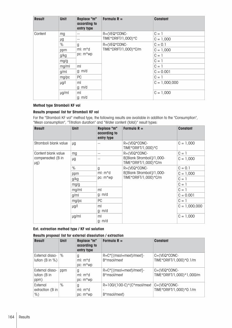
Result Unit Replace "m"according toentry type
Formula R = Constant
mg -- C = 1µg --
R=(VEQ*CONC-TIME*DRIFT/1,000)*C C = 1,000
% C = 0.1ppm C = 1,000g/kg C = 1mg/g
gml: m*dpc: m*wp
C = 1mg/ml C = 1g/ml
mlg: m/d C = 0.001
mg/pc PC C = 1µg/l ml
g: m/dC = 1,000,000
Content
µg/ml mlg: m/d
R=(VEQ*CONC-TIME*DRIFT/1,000)*C/m
C = 1,000
Method type Stromboli KF vol
Results proposal list for Stromboli KF volFor the "Stromboli KF vol" method type, the following results are available in addition to the "Consumption","Mean consumption", "Titration duration" and "Water content (total)" result types:
Result Unit Replace "m"according toentry type
Formula R = Constant
Stromboli blank value µg -- R=(VEQ*CONC-TIME*DRIFT/1,000)*C
C = 1,000
mg -- C = 1µg --
R=(VEQ*CONC-B[Blank Stromboli]/1,000-TIME*DRIFT/1,000)*C/m
C = 1,000
% C = 0.1ppm C = 1,000g/kg C = 1mg/g
gml: m*dpc: m*wp
C = 1mg/ml C = 1g/ml
mlg: m/d C = 0.001
mg/pc PC C = 1µg/l ml
g: m/dC = 1,000,000
Content blank valuecompensated (B inµg)
µg/ml mlg: m/d
R=(VEQ*CONC-B[Blank Stromboli]/1,000-TIME*DRIFT/1,000)*C/m
C = 1,000
Ext. extraction method type / KF vol solution
Results proposal list for external dissolution / extractionResult Unit Replace "m"
according toentry type
Formula R = Constant
External dissolution (B in %)
% gml: m*dpc: m*wp
R=C*[(msol+mext)/mext]-B*msol/mext
C=(VEQ*CONC-TIME*DRIFT/1,000)*0.1/m
External dissolution (B inppm)
ppm gml: m*dpc: m*wp
R=C*[(msol+mext)/mext]-B*msol/mext
C=(VEQ*CONC-TIME*DRIFT/1,000)*1,000/m
Externalextraction (B in%)
% gml: m*dpc: m*wp
R=100/(100-C)*(C*msol/mext-B*msol/mext)
C=(VEQ*CONC-TIME*DRIFT/1,000)*0.1/m
164 Results
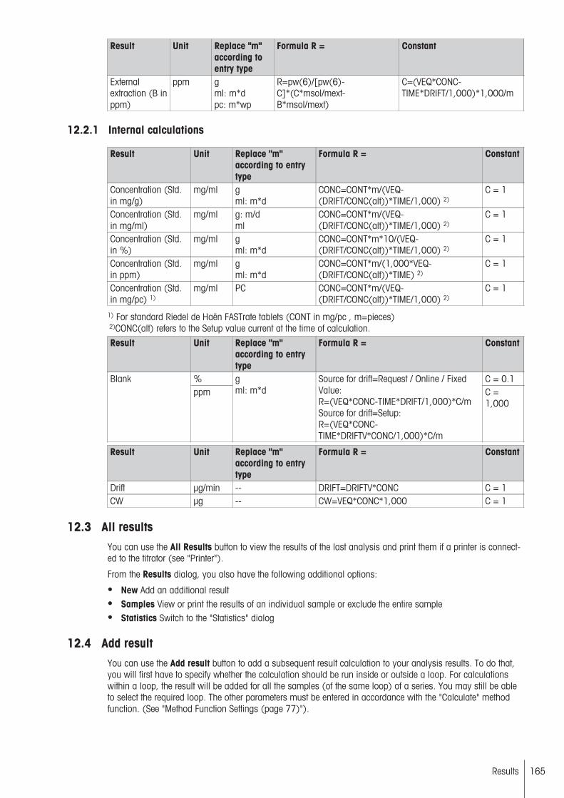
Result Unit Replace "m"according toentry type
Formula R = Constant
Externalextraction (B inppm)
ppm gml: m*dpc: m*wp
R=pw(6)/[pw(6)-C]*(C*msol/mext-B*msol/mext)
C=(VEQ*CONC-TIME*DRIFT/1,000)*1,000/m
12.2.1 Internal calculations
Result Unit Replace "m"according to entrytype
Formula R = Constant
Concentration (Std.in mg/g)
mg/ml gml: m*d
CONC=CONT*m/(VEQ-(DRIFT/CONC(alt))*TIME/1,000) 2)
C = 1
Concentration (Std.in mg/ml)
mg/ml g: m/dml
CONC=CONT*m/(VEQ-(DRIFT/CONC(alt))*TIME/1,000) 2)
C = 1
Concentration (Std.in %)
mg/ml gml: m*d
CONC=CONT*m*10/(VEQ-(DRIFT/CONC(alt))*TIME/1,000) 2)
C = 1
Concentration (Std.in ppm)
mg/ml gml: m*d
CONC=CONT*m/(1,000*VEQ-(DRIFT/CONC(alt))*TIME) 2)
C = 1
Concentration (Std.in mg/pc) 1)
mg/ml PC CONC=CONT*m/(VEQ-(DRIFT/CONC(alt))*TIME/1,000) 2)
C = 1
1) For standard Riedel de Haën FASTrate tablets (CONT in mg/pc , m=pieces) 2)CONC(alt) refers to the Setup value current at the time of calculation.
Result Unit Replace "m"according to entrytype
Formula R = Constant
% C = 0.1Blankppm
gml: m*d
Source for drift=Request / Online / FixedValue:R=(VEQ*CONC-TIME*DRIFT/1,000)*C/mSource for drift=Setup:R=(VEQ*CONC-TIME*DRIFTV*CONC/1,000)*C/m
C =1,000
Result Unit Replace "m"according to entrytype
Formula R = Constant
Drift µg/min -- DRIFT=DRIFTV*CONC C = 1CW µg -- CW=VEQ*CONC*1,000 C = 1
12.3 All resultsYou can use the All Results button to view the results of the last analysis and print them if a printer is connected to the titrator (see "Printer").
From the Results dialog, you also have the following additional options:
● New Add an additional result● Samples View or print the results of an individual sample or exclude the entire sample● Statistics Switch to the "Statistics" dialog
12.4 Add resultYou can use the Add result button to add a subsequent result calculation to your analysis results. To do that,you will first have to specify whether the calculation should be run inside or outside a loop. For calculationswithin a loop, the result will be added for all the samples (of the same loop) of a series. You may still be ableto select the required loop. The other parameters must be entered in accordance with the "Calculate" methodfunction. (See "Method Function Settings (page 77)").
165Results

You can use the Calculate button to calculate the additional result and add it to your analysis results. If you aremissing raw data or raw results for the calculation and cannot calculate the result for that reason, the result"NaN" (Not a number) will be added.
12.5 StatisticsFor results within a sample loop, you can display and print out statistics.
● The statistics are only created if more than one sample was analyzed in the corresponding loop.● If you selected "Statistics functionalities" = "Yes" and "Multiple determination" = "Yes" in the associated
"Calculate" method function, the system will create the statistics for the entire series and also individually formultiple samples within the series.
The following calculated values will be displayed as statistical components:
● Mean value x of a result Rx (Mean [Rx])● Standard deviation s● Relative standard deviation srel● Number of samples per loop nTOT
If a result was excluded from the statistics, all the results from that sample will always be excluded as well. Thesystem will then recalculate the statistics without the excluded sample and label them accordingly. If the sample's results are then put back into the statistical evaluation, the label will be removed from the statistics.
From the Statistics dialog, you also have the following additional options:
● Samples View, print, or exclude the results of an individual sample● Results View or print all results● Outlier test Perform a test for outliers in the statistical evaluation.
12.5.1 Outlier test
If the results of individual samples in a measurement series deviate greatly from the calculated mean value, itmay make sense to question the significance of these (few) results and treat them as "outliers".
Outliers will have the following effects on the overall result of an analysis:
● The mean value is significantly shifted higher or lower.● The standard deviation is increased.● The distribution of the individual values around the mean value is distorted and no longer follows a normal
distribution.
The titrator has an automatic function for identifying and labeling outliers. You can call this function from theStatistics dialog using the "Outlier test" softkey.
You can run an outlier test if you have the results from more than three samples.
The procedure used by the titrator is the Grubbs outlier test. For this procedure, the measured value [x*] thathas the greatest deviation from the calculated mean value is analyzed.This number is used in the followingequation, together with the mean value [x] and the standard deviation [s]:
PG = x - x*
s
The test variable [PG] is then compared with the corresponding value in the Grubbs table G (N, 90%), whichin turn depends on the number of measured values N:
N (number of samples) 1 2 3 4 5 6 7 8 9 1090 % - - 1.15 1.46 1.67 1.82 1.94 2.03 2.11 2.18N (number of samples) 11 12 13 14 15 16 17 18 19 2090 % 2.23 2.29 2.33 2.37 2.41 2.44 2.48 2.5 2.53 2.56N (number of samples) 21 22 23 24 25 26 27 28 29 3090 % 2.58 2.6 2.61 2.63 2.65 2.67 2.69 2.7 2.72 2.74N (number of samples) 31 32 33 34 35 36 37 38 39 4090 % 2.75 2.77 2.78 2.79 2.81 2.82 2.83 2.84 2.86 2.87
166 Results
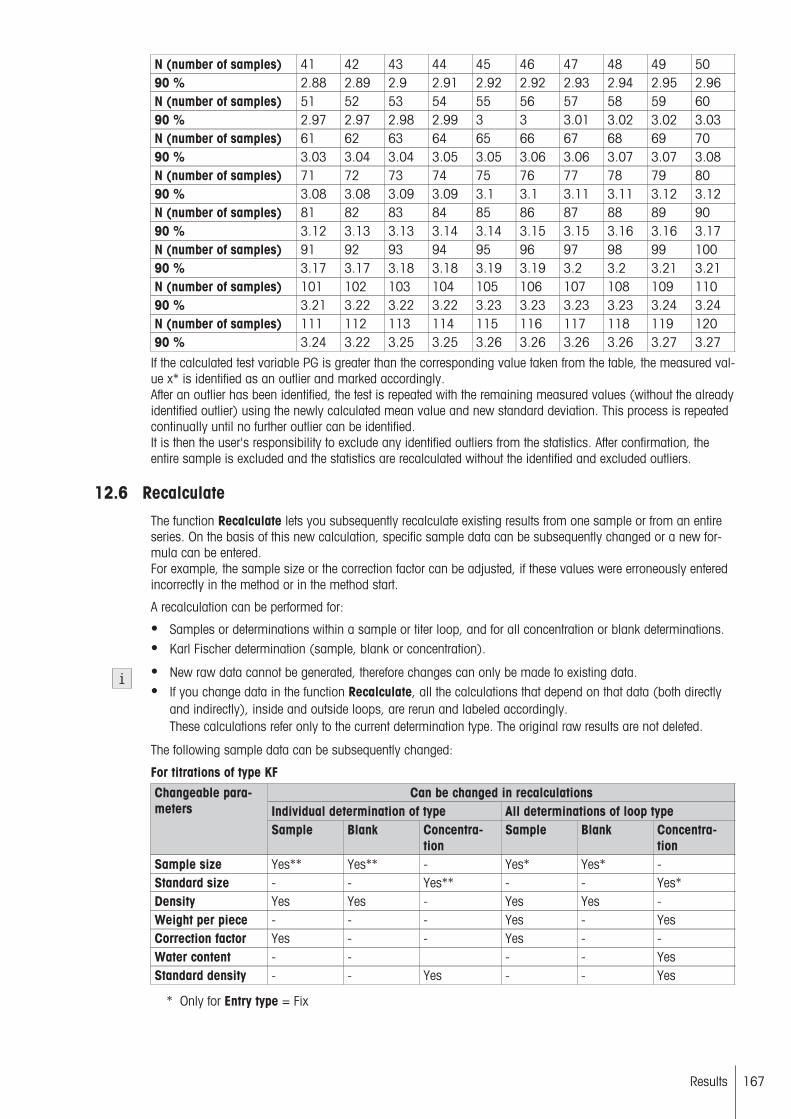
N (number of samples) 41 42 43 44 45 46 47 48 49 5090 % 2.88 2.89 2.9 2.91 2.92 2.92 2.93 2.94 2.95 2.96N (number of samples) 51 52 53 54 55 56 57 58 59 6090 % 2.97 2.97 2.98 2.99 3 3 3.01 3.02 3.02 3.03N (number of samples) 61 62 63 64 65 66 67 68 69 7090 % 3.03 3.04 3.04 3.05 3.05 3.06 3.06 3.07 3.07 3.08N (number of samples) 71 72 73 74 75 76 77 78 79 8090 % 3.08 3.08 3.09 3.09 3.1 3.1 3.11 3.11 3.12 3.12N (number of samples) 81 82 83 84 85 86 87 88 89 9090 % 3.12 3.13 3.13 3.14 3.14 3.15 3.15 3.16 3.16 3.17N (number of samples) 91 92 93 94 95 96 97 98 99 10090 % 3.17 3.17 3.18 3.18 3.19 3.19 3.2 3.2 3.21 3.21N (number of samples) 101 102 103 104 105 106 107 108 109 11090 % 3.21 3.22 3.22 3.22 3.23 3.23 3.23 3.23 3.24 3.24N (number of samples) 111 112 113 114 115 116 117 118 119 12090 % 3.24 3.22 3.25 3.25 3.26 3.26 3.26 3.26 3.27 3.27
If the calculated test variable PG is greater than the corresponding value taken from the table, the measured value x* is identified as an outlier and marked accordingly.After an outlier has been identified, the test is repeated with the remaining measured values (without the alreadyidentified outlier) using the newly calculated mean value and new standard deviation. This process is repeatedcontinually until no further outlier can be identified.It is then the user's responsibility to exclude any identified outliers from the statistics. After confirmation, theentire sample is excluded and the statistics are recalculated without the identified and excluded outliers.
12.6 RecalculateThe function Recalculate lets you subsequently recalculate existing results from one sample or from an entireseries. On the basis of this new calculation, specific sample data can be subsequently changed or a new formula can be entered.For example, the sample size or the correction factor can be adjusted, if these values were erroneously enteredincorrectly in the method or in the method start.
A recalculation can be performed for:
● Samples or determinations within a sample or titer loop, and for all concentration or blank determinations.● Karl Fischer determination (sample, blank or concentration).
● New raw data cannot be generated, therefore changes can only be made to existing data.● If you change data in the function Recalculate, all the calculations that depend on that data (both directly
and indirectly), inside and outside loops, are rerun and labeled accordingly.These calculations refer only to the current determination type. The original raw results are not deleted.
The following sample data can be subsequently changed:
For titrations of type KFCan be changed in recalculations
Individual determination of type All determinations of loop typeChangeable parameters
Sample Blank Concentration
Sample Blank Concentration
Sample size Yes** Yes** - Yes* Yes* -Standard size - - Yes** - - Yes*Density Yes Yes - Yes Yes -Weight per piece - - - Yes - YesCorrection factor Yes - - Yes - -Water content - - - - YesStandard density - - Yes - - Yes
* Only for Entry type = Fix
167Results
** Only for Entry type = Variable
12.7 SamplesYou can use the Samples button to display and print the status and calculated results for each individual sample. The same applies for a series of additional data sets that can be accessed via "Data". This will let you viewand print the sample, method and resource data for each sample and view and print the raw results and themeasured values.
You can use the Exclude button in the Results: Samples dialog to exclude individual samples from the statistical evaluation. The system will not delete the results of the samples excluded in this way but merely label themas excluded. They will no longer be included in the statistics. Samples that have been excluded can be returnedto the statistics at any time by choosing "Include".
After a sample is excluded, all affected calculations (inside and outside of loops) are performed again. In KFtitrations, the new calculations refer only to the current determination type.
If you exclude a sample from a sample group in a multiple determination, no more statistics will be generatedfor that group. The system will continue to create individual statistics for the remaining sample groups and forall the remaining samples overall.
12.8 ReevaluateThis function is only available if a method function Titration (EQP) or Titration (2-phase) is included in themethod. This function lets you make subsequent adjustments to the Recognition and evaluation criteria for anequivalence point and thus run a new evaluation of the measurement data.
If the method contains multiple titration functions, select the one whose recognition criteria you want to adjust.You can run a reevaluation for all the samples of a loop or for one specific sample in a loop.
You can adjust the following parameters in the subfunction Evaluation and Recognition:
● Procedure● Threshold● Add. EQP criteria● Tendency● Recognition
• Lower limit• Upper limit
● The reevaluation is only run for the selected sample (or samples) and the selected method function. All calculations affected directly or indirectly, inside or outside loops, will be rerun and the results obtained will belabeled.
● For the titrator model T90: Logical conditions (Condition) that determines whether or not a method functionis executed are ignored when recalculating any results.
12.9 Undo changesIf you make changes to the results saved by the titrator after the analysis, you can use Undo changes to discard them. Afterward, the system will reinstate the initial status directly after the conclusion of the analysis, in itsoriginal and unchanged state.
12.10 Delete all resultsYou can use this button to delete all the data (raw data, raw results, and results) saved by the titrator in theresults range.
For Karl Fischer (KF) titrations, the deletion only affects one determination type. If the last determination type ina KF sample series is deleted, the whole KF sample series is automatically deleted.
168 Results

12.11 Access to bufferThe results of a method can be stored in the buffer of the titrator and then reused. Results are stored in the bufferusing the "Calculation" method function and the "Send to buffer" parameter (see "Parameters of method functions (page 77)"). Results stored in the buffer may be accessed both from inside and outside a loop.
These results are assigned a unique method ID, allowing them to be reused for other calculations. They can beaccessed using the method of your choice, for example via Rx = Ry[method ID].
If, while an analysis is running, a method is waiting for a result with a corresponding method ID, the analysisprocess is interrupted until the relevant result is generated and present in the buffer.
● An analysis which is in this waiting state can only be ended using Reset or Stop. It is not possible to proceed without a result.
● Once the titrator has been restarted the buffer is empty. (Recalculation is only possible using older, internally stored analysis data, (see "Recalculation (page 167)").
● Implicit sample indexing ensures that the "Calculation" method for sample x only accesses results for sample x.
169Results

13 Appendix
13.1 Predefined calibration standards for pH sensorsMETTLER TOLEDO EU(Ref. 25°C)
METTLER TOLEDO USA(Ref. 25°C)
DIN (19266) /NIST (Ref.25°C)
DIN (19267) (Ref. 25°C) MERCK (Ref. 20°C)
2.00 1.68 1.680 1.09 1.004.01 4.01 3.557 3.06 2.004.60 7.00 3.775 4.65 3.007.00 10.01 4.008 6.79 4.009.21 6.865 9.23 4.6610.00 7.416 12.75 5.0011.00 9.184 6.00
10.014 6.8812.454 7.00
8.009.009.2210.0011.0012.0013.00
Fluka (Ref. 20°C) Novartis (Fluka) (Ref.20°C)
FISHER (Ref. 25°C) JIS Z 8802 (Ref. 25°C) JJG119 (Ref. 25°C)
1.00 4.00 1.00 1.679 1.6802.00 7.00 2.00 4.008 3.5593.00 9.00 3.00 6.865 4.0034.00 4.00 7.413 6.8645.00 5.00 9.180 7.4096.00 6.00 10.01 9.1827.00 7.00 12.4608.00 8.009.00 8.99110.00 10.0011.00 11.0012.0013.00
13.1.1 Temperature related values
13.1.1.1 METTLER TOLEDO
METTLER TOLEDO EU (Ref. 25°C)Temp. [°C] pH0 2.03 4.01 4.66 7.12 9.52 10.65 11.905 2.02 4.01 4.65 7.09 9.45 10.52 11.7210 2.01 4.00 4.64 7.06 9.38 10.39 11.5415 2.00 4.00 4.63 7.04 9.32 10.26 11.3620 2.00 4.00 4.62 7.02 9.26 10.13 11.1825 2.00 4.01 4.60 7.00 9.21 10.00 11.0030 1.99 4.01 4.61 6.99 9.16 9.87 10.8235 1.99 4.02 4.62 6.98 9.11 9.74 10.6440 1.98 4.03 4.63 6.97 9.06 9.61 10.4645 1.98 4.04 4.64 6.97 9.03 9.48 10.2850 1.98 4.06 4.66 6.97 8.99 9.35 10.1055 1.98 4.08 4.67 6.98 8.96 9.22 9.9260 1.98 4.10 4.69 6.98 8.93 9.09 9.7470 1.99 4.16 4.71 7.00 8.88 8.96 9.5680 2.00 4.22 4.73 7.04 8.83 8.83 9.3890 2.00 4.30 4.75 7.09 8.79 8.70 9.2095 2.00 4.35 4.77 7.12 8.77 8.57 9.02
170 Appendix

METTLER TOLEDO USA (Ref. 25°C)Temp. [°C] pH5 1.67 4.01 7.09 10.2510 1.67 4.00 7.06 10.1815 1.67 4.00 7.04 10.1220 1.68 4.00 7.02 10.0625 1.68 4.01 7.00 10.0130 1.68 4.01 6.99 9.9735 1.69 4.02 6.98 9.9340 1.69 4.03 6.97 9.8945 1.70 4.04 6.97 9.8650 1.71 4.06 6.97 9.83
13.1.1.2 DIN / NIST
DIN (19266) / NIST (Ref. 25°C)Temp. [°C] pH0 1.666 3.577 3.863 4.010 6.984 7.534 9.464 10.317 13.4235 1.668 3.573 3.837 4.004 6.950 7.502 9.392 10.248 13.20710 1.670 3.569 3.819 4.001 6.922 7.474 9.331 10.180 13.00315 1.672 3.565 3.801 4.001 6.900 7.451 9.277 10.121 12.81020 1.676 3.561 3.787 4.003 6.880 7.432 9.228 10.066 12.62725 1.680 3.557 3.775 4.008 6.865 7.416 9.184 10.014 12.45430 1.685 3.553 3.766 4.015 6.853 7.405 9.144 9.970 12.28935 1.691 3.549 3.759 4.026 6.845 7.396 9.110 9.928 12.13340 1.697 3.549 3.754 4.036 6.837 7.389 9.076 9.892 11.98445 1.704 3.544 3.751 4.049 6.834 7.386 9.046 9.856 11.84150 1.712 3.548 3.748 4.064 6.833 7.384 9.018 9.830 11.70555 1.715 3.554 3.750 4.075 6.834 7.382 8.985 9.804 11.57460 1.723 3.560 3.753 4.091 6.836 7.380 8.962 9.778 11.44970 1.743 3.580 3.763 4.126 6.845 7.378 8.921 9.752 11.32480 1.766 3.609 3.780 4.164 6.859 7.376 8.885 9.726 11.19990 1.792 3.650 3.802 4.205 6.877 7.374 8.850 9.700 11.07495 1.806 3.674 3.815 4.227 6.886 7.372 8.833 9.674 10.949
DIN (19267) (Ref. 25°C)Temp. [°C] pH0 1.08 3.12 4.67 6.89 9.48 13.895 1.08 3.11 4.67 6.87 9.43 13.6310 1.09 3.10 4.66 6.84 9.37 13.3715 1.09 3.09 4.66 6.82 9.32 13.1620 1.09 3.07 4.65 6.80 9.27 12.9625 1.09 3.06 4.65 6.79 9.23 12.7530 1.10 3.05 4.65 6.78 9.18 12.6135 1.10 3.05 4.65 6.77 9.13 12.4540 1.10 3.04 4.66 6.76 9.09 12.2945 1.10 3.04 4.67 6.76 9.04 12.0950 1.11 3.04 4.68 6.76 9.00 11.9860 1.11 3.04 4.70 6.76 8.92 11.6970 1.11 3.04 4.72 6.76 8.88 11.4380 1.12 3.05 4.75 6.78 8.85 11.1990 1.13 3.07 4.79 6.80 8.82 10.99
13.1.1.3 MERCK
MERCK (Ref. 20°C)Temp. [°C] pH0 0.96 2.01 3.05 4.05 4.68 5.06 6.04 6.985 0.99 2.01 3.05 4.04 4.68 5.05 6.02 6.9510 0.99 2.01 3.03 4.02 4.67 5.02 6.01 6.9215 0.99 2.00 3.01 4.01 4.67 5.01 6.00 6.9020 1.00 2.00 3.00 4.00 4.66 5.00 6.00 6.8825 1.01 2.00 3.00 4.01 4.66 5.00 6.02 6.86
171Appendix

Temp. [°C] pH30 1.01 2.00 3.00 4.01 4.66 5.00 6.03 6.8635 1.01 2.00 3.00 4.01 4.66 5.00 6.03 6.8540 1.01 2.00 2.98 4.01 4.67 5.00 6.04 6.8445 1.01 2.00 2.98 4.01 4.67 5.01 6.05 6.8450 1.01 2.00 2.97 4.00 4.68 5.01 6.06 6.8460 1.02 2.00 2.97 4.00 4.69 5.04 6.10 6.8470 1.02 2.01 2.97 4.00 4.70 5.05 6.12 6.8480 1.02 2.01 2.97 4.00 4.71 5.10 6.17 6.8690 1.02 2.01 2.96 4.00 4.72 5.14 6.24 6.88
MERCK (Ref. 20°C) (continued)Temp. [°C] pH0 7.13 8.15 9.24 9.46 10.26 11.45 12.58 13.805 7.07 8.10 9.16 9.40 10.17 11.32 12.41 13.5910 7.05 8.07 9.11 9.33 10.11 11.20 12.26 13.3715 7.02 8.04 9.05 9.28 10.05 11.10 12.10 13.1820 7.00 8.00 9.00 9.22 10.00 11.00 12.00 13.0025 6.98 7.96 8.95 9.18 9.94 10.90 11.88 12.8330 6.98 7.94 8.91 9.14 9.89 10.81 11.72 12.6735 6.96 7.92 8.88 9.10 9.84 10.72 11.67 12.5940 6.95 7.90 8.85 9.07 9.83 10.64 11.54 12.4145 6.95 7.88 8.82 9.04 9.79 10.56 11.44 12.2850 6.95 7.85 8.79 9.01 9.74 10.48 11.33 12.1560 6.96 7.83 8.73 8.96 9.67 10.33 11.04 11.7570 6.96 7.80 8.70 8.93 9.62 10.19 10.90 11.6180 6.97 7.78 8.66 8.89 9.55 10.06 10.70 11.3990 7.00 7.75 8.64 8.85 9.49 9.93 10.48 11.15
13.1.1.4 FLUKA
FLUKA (Ref. 20°C)Temp. [°C] pH0 0.94 1.99 3.03 4.03 5.05 6.0310 0.99 1.99 3.02 4.02 5.02 6.0120 1.00 2.00 3.00 4.00 5.00 6.0030 1.00 2.00 3.00 4.00 5.00 6.0240 1.01 2.00 2.99 4.00 5.00 6.0450 1.01 2.00 2.98 4.00 5.02 6.0660 1.01 2.00 2.98 4.00 5.04 6.0970 1.01 2.00 2.98 4.00 5.07 6.1380 1.02 2.00 2.98 4.00 5.10 6.1890 1.02 2.00 2.97 4.00 5.13 6.24
FLUKA (Ref. 20°C) (continued)Temp. [°C] pH0 7.13 8.18 9.24 10.24 11.45 12.58 13.7110 7.05 8.09 9.11 10.10 11.20 12.26 13.3520 7.00 8.00 9.00 10.00 11.00 12.00 13.0030 6.98 7.94 8.93 9.90 10.81 11.75 12.6640 6.97 7.90 8.86 9.82 10.64 11.53 12.3750 6.96 7.86 8.80 9.75 10.48 11.31 12.1060 6.96 7.82 8.75 9.68 10.33 11.09 11.8470 6.97 7.80 8.71 9.62 10.19 10.88 11.6180 6.98 7.77 8.67 9.55 10.06 10.68 11.4090 7.00 7.75 8.64 9.49 9.93 10.48 11.20
NOVARTIS (FLUKA) (Ref. 20°C)Temp. [°C] pH0 4.01 7.11 9.205 4.00 7.08 9.1510 4.00 7.05 9.1015 4.00 7.02 9.0520 4.00 7.00 9.00
172 Appendix
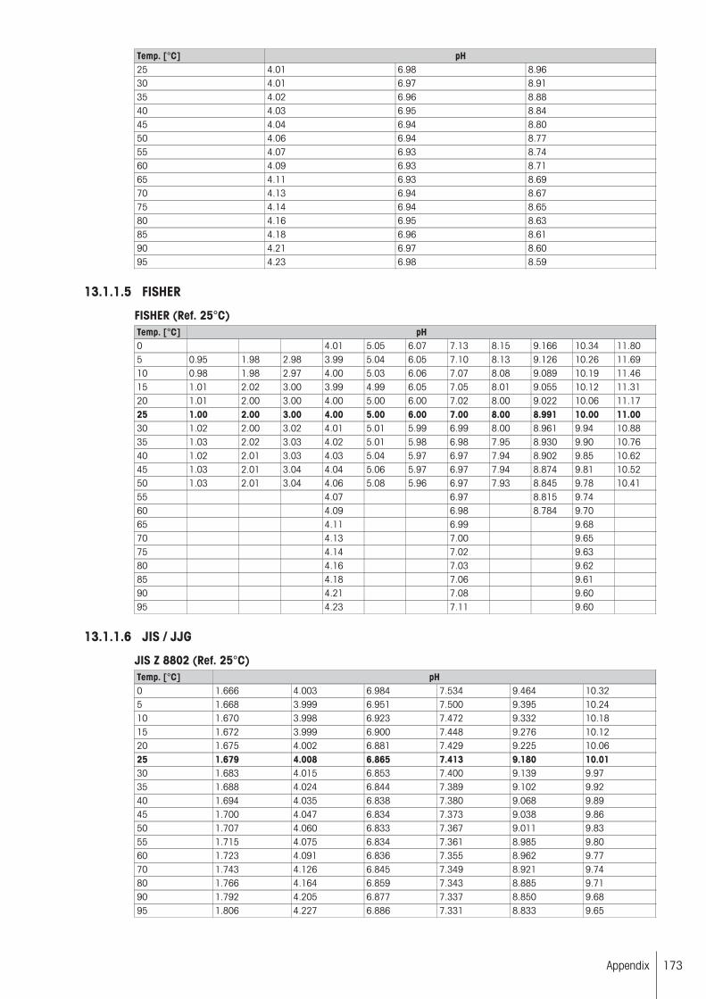
Temp. [°C] pH25 4.01 6.98 8.9630 4.01 6.97 8.9135 4.02 6.96 8.8840 4.03 6.95 8.8445 4.04 6.94 8.8050 4.06 6.94 8.7755 4.07 6.93 8.7460 4.09 6.93 8.7165 4.11 6.93 8.6970 4.13 6.94 8.6775 4.14 6.94 8.6580 4.16 6.95 8.6385 4.18 6.96 8.6190 4.21 6.97 8.6095 4.23 6.98 8.59
13.1.1.5 FISHER
FISHER (Ref. 25°C)Temp. [°C] pH0 4.01 5.05 6.07 7.13 8.15 9.166 10.34 11.805 0.95 1.98 2.98 3.99 5.04 6.05 7.10 8.13 9.126 10.26 11.6910 0.98 1.98 2.97 4.00 5.03 6.06 7.07 8.08 9.089 10.19 11.4615 1.01 2.02 3.00 3.99 4.99 6.05 7.05 8.01 9.055 10.12 11.3120 1.01 2.00 3.00 4.00 5.00 6.00 7.02 8.00 9.022 10.06 11.1725 1.00 2.00 3.00 4.00 5.00 6.00 7.00 8.00 8.991 10.00 11.0030 1.02 2.00 3.02 4.01 5.01 5.99 6.99 8.00 8.961 9.94 10.8835 1.03 2.02 3.03 4.02 5.01 5.98 6.98 7.95 8.930 9.90 10.7640 1.02 2.01 3.03 4.03 5.04 5.97 6.97 7.94 8.902 9.85 10.6245 1.03 2.01 3.04 4.04 5.06 5.97 6.97 7.94 8.874 9.81 10.5250 1.03 2.01 3.04 4.06 5.08 5.96 6.97 7.93 8.845 9.78 10.4155 4.07 6.97 8.815 9.7460 4.09 6.98 8.784 9.7065 4.11 6.99 9.6870 4.13 7.00 9.6575 4.14 7.02 9.6380 4.16 7.03 9.6285 4.18 7.06 9.6190 4.21 7.08 9.6095 4.23 7.11 9.60
13.1.1.6 JIS / JJG
JIS Z 8802 (Ref. 25°C)Temp. [°C] pH0 1.666 4.003 6.984 7.534 9.464 10.325 1.668 3.999 6.951 7.500 9.395 10.2410 1.670 3.998 6.923 7.472 9.332 10.1815 1.672 3.999 6.900 7.448 9.276 10.1220 1.675 4.002 6.881 7.429 9.225 10.0625 1.679 4.008 6.865 7.413 9.180 10.0130 1.683 4.015 6.853 7.400 9.139 9.9735 1.688 4.024 6.844 7.389 9.102 9.9240 1.694 4.035 6.838 7.380 9.068 9.8945 1.700 4.047 6.834 7.373 9.038 9.8650 1.707 4.060 6.833 7.367 9.011 9.8355 1.715 4.075 6.834 7.361 8.985 9.8060 1.723 4.091 6.836 7.355 8.962 9.7770 1.743 4.126 6.845 7.349 8.921 9.7480 1.766 4.164 6.859 7.343 8.885 9.7190 1.792 4.205 6.877 7.337 8.850 9.6895 1.806 4.227 6.886 7.331 8.833 9.65
173Appendix

JJG119 (Ref. 25°C)Temp. [°C] pH0 1.668 3.599 4.006 6.981 7.515 9.458 13.4165 1.669 3.591 3.999 6.949 7.490 9.391 13.21010 1.671 3.583 3.996 6.921 7.467 9.330 13.01115 1.673 3.575 3.996 6.898 7.445 9.276 12.82020 1.676 3.567 3.998 6.879 7.426 9.226 12.63725 1.680 3.559 4.003 6.864 7.409 9.182 12.46030 1.684 3.551 4.010 6.852 7.395 9.142 12.29235 1.688 3.547 4.019 6.844 7.386 9.105 12.13040 1.694 3.547 4.029 6.838 7.380 9.072 11.97545 1.700 3.550 4.042 6.834 7.379 9.042 11.82850 1.706 3.555 4.055 6.833 7.383 9.015 11.69755 1.713 3.563 4.070 6.834 7.387 8.990 11.55360 1.721 3.573 4.087 6.837 7.391 8.968 11.42670 1.739 3.596 4.122 6.847 7.399 8.926 11.17280 1.759 3.622 4.161 6.862 7.407 8.890 10.91890 1.782 3.648 4.203 6.881 7.415 8.856 10.66495 1.795 3.660 4.224 6.891 7.419 8.839 10.537
13.2 Predefined calibration standards for conductivity sensorsList name REAGECON (Ref. 25°C) METTLER TOLEDO (Ref. 25 °C)
1.3 µS/cm5 µS/cm10 µS/cm20 µS/cm50 µS/cm84 µS/cm 84 µS/cm100 µS/cm147 µS/cm200 µS/cm500 µS/cm1000 µS/cm1413 µS/cm 1413 µS/cm5 mS/cm10 mS/cm12.88 mS/cm 12.88 mS/cm20 mS/cm50 mS/cm100 mS/cm150 mS/cm200 mS/cm300 mS/cm350 mS/cm450 mS/cm
Included Conductivity Standards
500 mS/cm
13.2.1 Temperature related values
13.2.1.1 REAGECON
Ref. 25°CTemp. °C Conductivity [µS/cm]5 0.67 3.02 6.13 12.67 31.43 53.02 62.82 92.710 0.82 3.47 7.10 14.36 35.89 60.34 71.64 105.615 0.97 3.97 7.95 16.11 40.23 67.61 80.56 118.516 1.00 4.07 8.15 16.50 41.21 69.25 82.50 121.417 1.03 4.18 8.37 16.89 42.18 70.89 84.45 124.218 1.07 4.28 8.56 17.28 43.16 72.52 86.39 127.119 1.10 4.38 8.78 17.67 44.14 74.16 88.33 129.920 1.13 4.48 8.97 18.06 45.13 75.80 90.28 132.8
174 Appendix

Temp. °C Conductivity [µS/cm]21 1.16 4.59 9.18 18.44 46.10 77.44 92.22 135.622 1.20 4.69 9.38 18.83 47.08 79.08 94.17 138.523 1.23 4.79 9.59 19.22 48.05 80.72 96.11 141.324 1.27 4.90 9.79 19.61 49.03 82.36 98.06 144.225 1.30 5.00 10.00 20.00 50.00 84.00 100.00 147.026 1.33 5.10 10.21 20.39 50.99 85.64 101.95 149.827 1.35 5.21 10.41 20.78 51.95 87.28 103.89 152.728 1.38 5.31 10.62 21.17 52.93 88.91 105.83 155.529 1.40 5.41 10.82 21.56 53.91 90.55 107.78 158.430 1.43 5.52 11.03 21.95 54.88 92.19 109.72 161.235 1.58 6.07 12.14 24.06 60.06 100.92 119.69 177.040 1.74 6.63 13.29 26.16 65.22 109.21 130.17 191.545 1.88 7.15 14.44 28.38 70.57 118.05 140.67 207.450 2.04 7.66 15.55 30.67 76.08 126.80 151.35 222.9
REAGECON (Ref. 25°C) (continued)Temp. °C Conductivity [µS/cm]5 127.3 315.3 633 894 3182 6367 8216 1281010 144.8 359.6 718 1007 3616 7234 9326 1451215 161.7 402.9 808 1139 4047 8104 10439 1623916 165.5 412.6 827 1167 4142 8294 10684 1661517 169.3 422.4 846 1194 4237 8484 10929 1699118 173.2 432.1 865 1221 4333 8673 11174 1736719 177.0 441.8 885 1249 4428 8863 11419 1774320 180.8 451.5 904 1276 4523 9052 11664 1811921 184.7 461.2 923 1304 4619 9242 11909 1849622 188.5 470.9 942 1331 4714 9431 12153 1887223 192.3 480.6 962 1358 4809 9621 12398 1924824 196.2 490.3 981 1386 4905 9810 12643 1962425 200.0 500.0 1000 1413 5000 10000 12880 2000026 203.8 509.7 1019 1440 5095 10190 13133 2037627 207.7 519.4 1038 1468 5191 10379 13378 2075228 211.5 529.1 1058 1495 5286 10569 13623 2112829 215.3 538.8 1077 1522 5381 10758 13867 2150530 219.2 548.5 1096 1550 5477 10948 14112 2188135 240.0 602.5 1200 1694 5985 11952 15392 2386940 260.6 655.3 1301 1833 6501 12954 16678 2583245 282.0 710.1 1406 1989 7013 14006 18024 2787650 303.4 764.6 1517 2139 7515 15032 19338 29922
REAGECON (Ref. 25°C) (continued)Temp. °C Conductivity [µS/cm]5 32431 66141 100922 136689 210384 248247 321335 35680410 36592 74301 112456 152103 232327 272909 353892 39287415 40798 82458 124602 167414 254120 298010 385574 42903316 41719 84212 127142 170673 258708 303209 392017 43613017 42639 85967 129682 173931 263296 308408 398459 44322718 43559 87721 132222 177190 267884 313607 404902 45032319 44479 89475 134761 180448 272472 318806 411344 45742020 45399 91229 137301 183707 277060 324005 417787 46451721 46319 92983 139841 186966 281648 329204 424230 47161322 47240 94737 142381 190224 286236 334403 430672 47871023 48160 96492 144920 193483 290824 339602 437115 48580724 49080 98246 147460 196741 295412 344801 443557 49290325 50000 100000 150000 200000 300000 350000 450000 50000026 50920 101754 152540 203259 304588 355199 456443 50709727 51840 103508 155080 206517 309176 360398 462885 51419328 52761 105263 157619 209776 313764 365597 469328 52129029 53681 107017 160159 213034 318352 370796 475770 52838730 54601 108771 162699 216293 322940 375995 482213 53548335 59334 118005 175829 233217 346228 402200 512500 56846840 64070 127035 188666 249976 369429 428442 543966 60313145 69002 135799 202203 266899 393776 454931 573348 636054
175Appendix

Temp. °C Conductivity [µS/cm]50 74014 145808 215472 284025 417233 481705 601515 667245
13.2.1.2 METTLER TOLEDO
Ref. 25°CTemp. °C Conductivity [µS/cm]5 53.02 894 821610 60.34 1007 932615 67.61 1139 1043916 69.25 1167 1068417 70.89 1194 1092918 72.52 1221 1117419 74.16 1249 1141920 75.80 1276 1166421 77.44 1304 1190922 79.08 1331 1215323 80.72 1358 1239824 82.36 1386 1264325 84.00 1413 1288026 85.64 1440 1313327 87.28 1468 1337828 88.91 1495 1362329 90.55 1522 1386730 92.19 1550 1411235 100.92 1694 1539240 109.21 1833 1667845 118.05 1989 1802450 126.80 2139 19338
13.3 Karl Fischer Water Determination - Measuring PrincipleThe Karl Fischer procedure is a titration method used for the quantitative determination of water content in liquids and solids. Karl Fischer titration is used in a variety of areas, e.g. for determining the water content of groceries, chemicals, pharmaceuticals, cosmetics and mineral oils.
To determine the water content, first sulfur dioxide and water react with iodine:
2 H2O + SO2 + I2 SO42− + 2 I− + 4 H+
The addition of alcohol (e.g. methanol, ethanol), causes a preliminary reaction to take place in which sulfurdioxide forms an acidic ester, which is then neutralized by the addition of a base (e.g. imidazole, referred to inthe following as "RN"):
CH3OH + SO2 + RN (RNH)·(CH3OSO2)
In the presence of water, the alkyl sulfite anion is oxidized to alkyl sulfate by the iodine. This process reducesthe yellow-brown iodine to colorless iodide:
(RNH)·(CH3OSO2) + I2 + H2O + 2 RN (RNH)·(CH3OSO3) + 2 (RNH)·I
The overall reaction proceeds as follows:
H2O + I2 + SO2 + CH3OH + 3 RN [RNH]SO4CH3 + 2 [RNH]I
The reaction runs until all the water has been consumed and hence free iodine is detected in the titration solution. The end point is determined using bivoltametric indication, i.e. the potential at the polarized double-platinum-pin electrode falls below a certain value (e.g. 100mV).
176 Appendix
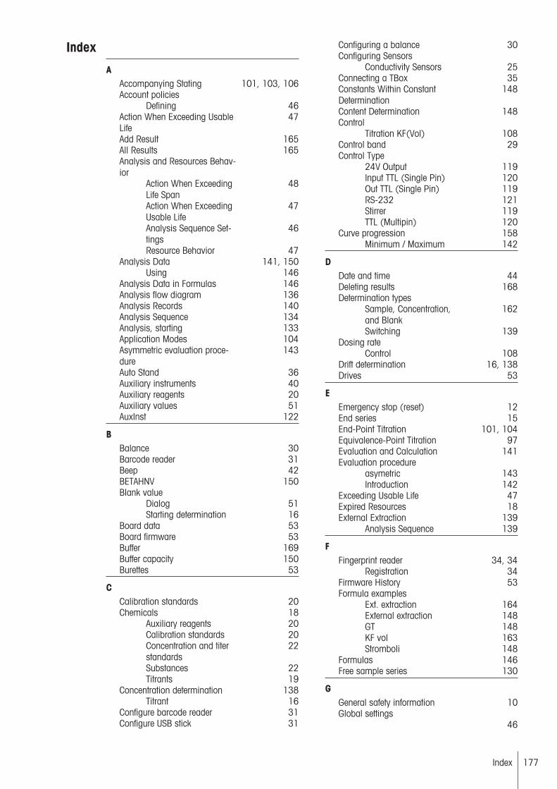
Index
AAccompanying Stating 101, 103, 106Account policies
Defining 46Action When Exceeding UsableLife
47
Add Result 165All Results 165Analysis and Resources Behavior
Action When ExceedingLife Span
48
Action When ExceedingUsable Life
47
Analysis Sequence Settings
46
Resource Behavior 47Analysis Data 141, 150
Using 146Analysis Data in Formulas 146Analysis flow diagram 136Analysis Records 140Analysis Sequence 134Analysis, starting 133Application Modes 104Asymmetric evaluation procedure
143
Auto Stand 36Auxiliary instruments 40Auxiliary reagents 20Auxiliary values 51AuxInst 122
BBalance 30Barcode reader 31Beep 42BETAHNV 150Blank value
Dialog 51Starting determination 16
Board data 53Board firmware 53Buffer 169Buffer capacity 150Burettes 53
CCalibration standards 20Chemicals 18
Auxiliary reagents 20Calibration standards 20Concentration and titerstandards
22
Substances 22Titrants 19
Concentration determination 138Titrant 16
Configure barcode reader 31Configure USB stick 31
Configuring a balance 30Configuring Sensors
Conductivity Sensors 25Connecting a TBox 35Constants Within ConstantDetermination
148
Content Determination 148Control
Titration KF(Vol) 108Control band 29Control Type
24V Output 119Input TTL (Single Pin) 120Out TTL (Single Pin) 119RS-232 121Stirrer 119TTL (Multipin) 120
Curve progression 158Minimum / Maximum 142
DDate and time 44Deleting results 168Determination types
Sample, Concentration,and Blank
162
Switching 139Dosing rate
Control 108Drift determination 16, 138Drives 53
EEmergency stop (reset) 12End series 15End-Point Titration 101, 104Equivalence-Point Titration 97Evaluation and Calculation 141Evaluation procedure
asymetric 143Introduction 142
Exceeding Usable Life 47Expired Resources 18External Extraction 139
Analysis Sequence 139
FFingerprint reader 34, 34
Registration 34Firmware History 53Formula examples
Ext. extraction 164External extraction 148GT 148KF vol 163Stromboli 148
Formulas 146Free sample series 130
GGeneral safety information 10Global settings
46
Index 177

Analysis and ResourcesBehaviorSystem 43User Management 44
HHardware 23
Balance 30Barcode reader 31Fingerprint reader 34LevelSens 35Network settings 34PC settings 33Peripherals 30, 30Printer 31Sensors 23TBox 35USB-Stick 31
Homescreen 12Homogenizer 41
Methods 125TTL / RS 125
IIdentification, titrator 43Import/Export, data 52Info button 12InMotion 38Internal calculations 165
Blank determinations 165Concentration determination
165
Interrupt AnalysisTitrator 72User 72
Ion Selective Sensors 26ISE Sensors 26
KKarl Fischer titration 108
Measurement principle 176Keyboard layout
Define 43KF Stand 39
LLanguage, setting 42Layout of terminal 12Learn Titration (EQP) 107Level sensor 35LevelSens 35
Activate 35Life Span 49Linear Calibration 27Liquid Handler 41Loop
Insertion and Deletion 74Types and numbers 73
Loop TypeCalibration Loop 131Karl Fischer 131Sample Loop 131
132
Sample Loop for FreeSample SeriesTiter Loop 131
MManual operation
Auxiliary instruments 63Burette 58Conductivity sensor 57Dispense 59Manual titration 60Polarized sensor 57Potentiometric Sensor 56Pump 62Sample changer 65Temperature Sensor 55
Manual operationsSensor 55Stirrer 54
Manual Stand 36Mathematical functions andoperators
149
Measure (MVT) 96Measure (Normal) 93Measured Values 17Method
Delete 71Start 71
Method editor 67Method functions
Indexing 145Maximum number 76Outside of Loop 127Overview 74Parameters 77Pretitration 126Standby 126, 126Within Loop 126, 126
Method functions, parametersAuxiliary Instrument 119Auxiliary value 117Blank Value 118Calculation 114Calibration 116Conditioning 90Dispense (Controlled) 112Dispense (Normal) 92Drain 123Drift Determination 125End of Sample 116Instruction 122Line rinse 86Measure (MVT) 96Measure (Normal) 93Mix Time 89Park 91Pump 90Record 123Rinse 89Sample 78Sample (Calibration) 79Sample (KF) 81
Index178
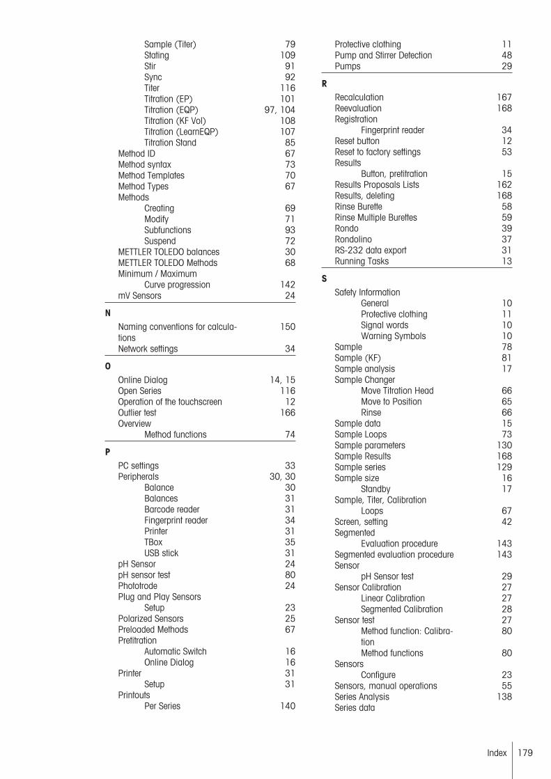
Sample (Titer) 79Stating 109Stir 91Sync 92Titer 116Titration (EP) 101Titration (EQP) 97, 104Titration (KF Vol) 108Titration (LearnEQP) 107Titration Stand 85
Method ID 67Method syntax 73Method Templates 70Method Types 67Methods
Creating 69Modify 71Subfunctions 93Suspend 72
METTLER TOLEDO balances 30METTLER TOLEDO Methods 68Minimum / Maximum
Curve progression 142mV Sensors 24
NNaming conventions for calculations
150
Network settings 34
OOnline Dialog 14, 15Open Series 116Operation of the touchscreen 12Outlier test 166Overview
Method functions 74
PPC settings 33Peripherals 30, 30
Balance 30Balances 31Barcode reader 31Fingerprint reader 34Printer 31TBox 35USB stick 31
pH Sensor 24pH sensor test 80Phototrode 24Plug and Play Sensors
Setup 23Polarized Sensors 25Preloaded Methods 67Pretitration
Automatic Switch 16Online Dialog 16
Printer 31Setup 31
PrintoutsPer Series 140
Protective clothing 11Pump and Stirrer Detection 48Pumps 29
RRecalculation 167Reevaluation 168Registration
Fingerprint reader 34Reset button 12Reset to factory settings 53Results
Button, pretitration 15Results Proposals Lists 162Results, deleting 168Rinse Burette 58Rinse Multiple Burettes 59Rondo 39Rondolino 37RS-232 data export 31Running Tasks 13
SSafety Information
General 10Protective clothing 11Signal words 10Warning Symbols 10
Sample 78Sample (KF) 81Sample analysis 17Sample Changer
Move Titration Head 66Move to Position 65Rinse 66
Sample data 15Sample Loops 73Sample parameters 130Sample Results 168Sample series 129Sample size 16
Standby 17Sample, Titer, Calibration
Loops 67Screen, setting 42Segmented
Evaluation procedure 143Segmented evaluation procedure 143Sensor
pH Sensor test 29Sensor Calibration 27
Linear Calibration 27Segmented Calibration 28
Sensor test 27Method function: Calibration
80
Method functions 80Sensors
Configure 23Sensors, manual operations 55Series Analysis 138Series data
Index 179
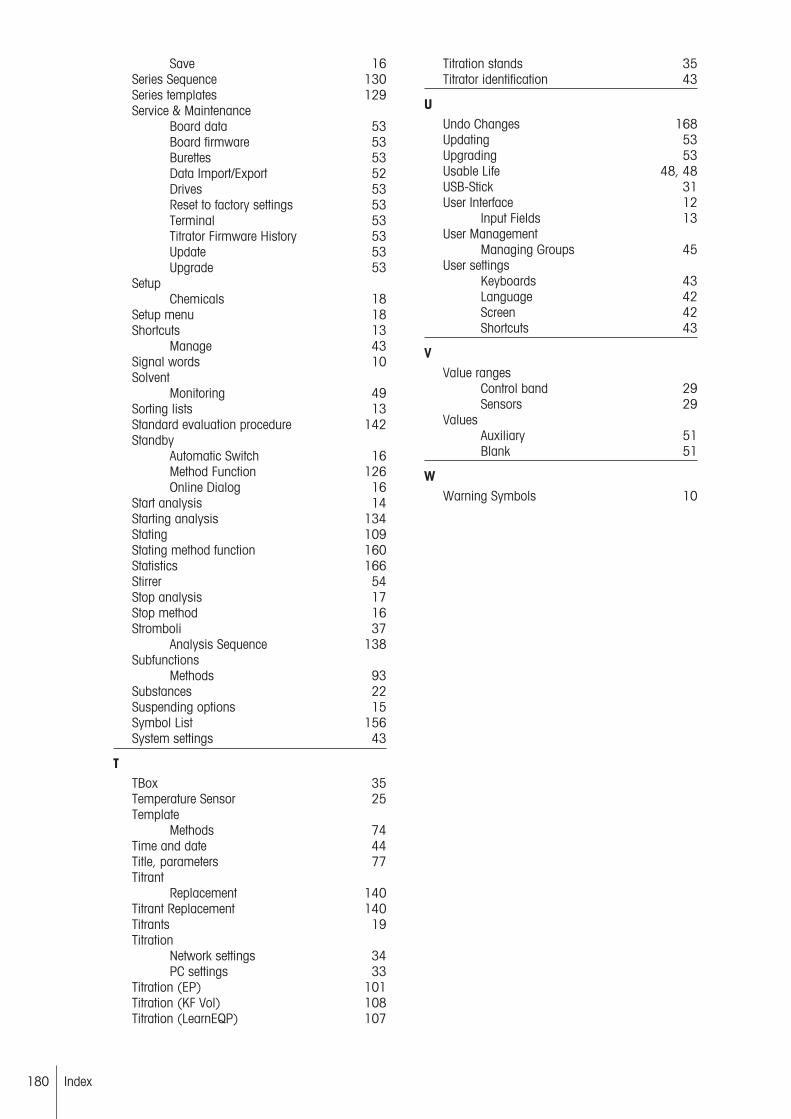
Save 16Series Sequence 130Series templates 129Service & Maintenance
Board data 53Board firmware 53Burettes 53Data Import/Export 52Drives 53Reset to factory settings 53Terminal 53Titrator Firmware History 53Update 53Upgrade 53
SetupChemicals 18
Setup menu 18Shortcuts 13
Manage 43Signal words 10Solvent
Monitoring 49Sorting lists 13Standard evaluation procedure 142Standby
Automatic Switch 16Method Function 126Online Dialog 16
Start analysis 14Starting analysis 134Stating 109Stating method function 160Statistics 166Stirrer 54Stop analysis 17Stop method 16Stromboli 37
Analysis Sequence 138Subfunctions
Methods 93Substances 22Suspending options 15Symbol List 156System settings 43
TTBox 35Temperature Sensor 25Template
Methods 74Time and date 44Title, parameters 77Titrant
Replacement 140Titrant Replacement 140Titrants 19Titration
Network settings 34PC settings 33
Titration (EP) 101Titration (KF Vol) 108Titration (LearnEQP) 107
Titration stands 35Titrator identification 43
UUndo Changes 168Updating 53Upgrading 53Usable Life 48, 48USB-Stick 31User Interface 12
Input Fields 13User Management
Managing Groups 45User settings
Keyboards 43Language 42Screen 42Shortcuts 43
VValue ranges
Control band 29Sensors 29
ValuesAuxiliary 51Blank 51
WWarning Symbols 10
Index180


*51710389*
For more informationwww.mt.com/titration
Mettler-Toledo AG, AnalyticalCH-8603 Schwerzenbach, SwitzerlandTel. +41 (0)44 806 77 11Fax +41 (0)44 806 73 50www.mt.com
Subject to technical changes.© Mettler-Toledo AG 11/201351710389G