Embed Size (px)
Citation preview

Title Page --Steel Snubber Arm
A Design Study in Steel Castings
Snubber Arm for the Dipper Door Control on Mining Shovels
Design Study OutlineIntroductionDesign for Performance Steel Alloy SelectionDesign for Production Molding Method Near-Net Shape Features Orientation in the Mold Riser DesignCasting Process Heat Treatment and MachiningQuality AssuranceLessons Learned and Summary
Key Words = metal casting, steel, snubber arm, Spokane Industires, 4320 alloy, SFSA, Start the Design Study !
Acknowledgment -- The metalcasting design studies are a joint effort of the
Steel Founders' Society of America and the American Foundry Society.Project funding was provided by the American Metalcasting Consortium Project, which
is sponsored by the Defense Logistics Agency, Attn: DLSC-T, Ft. Belvoir, VA, 22060-6221
SFSAHome Page
Copyright 2011 by the Steel Founders' Society of America All rights reserved. Address comments to: [email protected] Modified:September, 2011 by STG
In cooperation with Spokane Industries - Steel
Castings Division
file:///C|/Documents%20and%20Settings/Stephen%20Gonczy...%20Documents/My%20Webs/myweb2/DipperDoorHTML/index.htm [9/23/2011 2:53:29 PM]

Application 1
A Design Study in Steel - Spokane Industries Steel Snubber Arm
Snubber Arm -- Application Electric mining shovels are engineering vehicles used for the excavation and removal of overburden and ore in open-cut surface mining operations. These
electric power shovels are the modern equivalent of steam shovels and operate in a similar fashion.
The mining shovels have five major components -
● a revolving deck with a power plant● a front boom or crane which supports a
handle with a dipper/bucket at the end● a base platform with tracks or wheels ● a driving and control system ● and usually a counterweight.
The shovel electric systems (with multiple electric motors for hoist, swing, crowd, and propel) have power requirements as high as 3750 kVA .
Electric Mining Shovel
These shovels are the work horses in modern surface mining around the world.
Back Next 2
SFSAHome Page
Copyright 2011 by the Steel Founders' Society of America All rights reserved. Address comments to: [email protected]
Last Modified:August, 2011 by STGPage 1
In cooperation with Spokane Industries - Steel
Castings Division
file:///C|/Documents%20and%20Settings/Stephen%20Goncz...0Documents/My%20Webs/myweb2/DipperDoorHTML/SSA_02.htm [9/23/2011 2:53:37 PM]

Application 2
A Design Study in Steel - Spokane Industries Steel Snubber Arm
Snubber Arm -- Application
Shovel Dipper
The dipper/bucket is the digging and loading tool on the mining shovel.
Dippers can be as large as 12 x 12 x 15 feet with nominal volume and weight payload capacities up to 80 cubic yards and 100 tons.
The dipper has a bottom swing door which is latch closed during digging and drops open to dump the payload into the truck bed.
The dipper door itself has a weight of 25,000 pounds and a full load on the dipper door is up to 110 tons. The door commonly has damping devices to eliminate unrestrained swinging and to
prevent impact damage from "banging" and "slamming."
Back Next 3
SFSAHome Page
Copyright 2011 by the Steel Founders' Society of America All rights reserved. Address comments to: [email protected]
Last Modified:August, 2011 by STGPage 1
In cooperation with Spokane Industries - Steel
Castings Division
file:///C|/Documents%20and%20Settings/Stephen%20Goncz...0Documents/My%20Webs/myweb2/DipperDoorHTML/SSA_03.htm [9/23/2011 2:53:42 PM]

Description 1
A Design Study in Steel - Spokane Industries Steel Snubber Arm
Snubber Arm -- DescriptionP&H Mining uses a hydraulic damping control system, called SnubRite®,
on all its electric power shovels. This patented device is self-contained and uses a cushion of oil to dampen door travel. Two
damping controls are used, one on each side of the dipper.
Dipper Door SnubRite® Damper
The snubber arm is part of the dipper damping system. It is the steel arm that connects the door swing linkage to the rotary damper mechanism.
Back Next 4
SFSAHome Page
Copyright 2011 by the Steel Founders' Society of America All rights reserved. Address comments to: [email protected]
Last Modified:August, 2011 by STGPage 1
In cooperation with Spokane Industries - Steel
Castings Division
file:///C|/Documents%20and%20Settings/Stephen%20Goncz...0Documents/My%20Webs/myweb2/DipperDoorHTML/SSA_04.htm [9/23/2011 2:53:45 PM]

Description 2
A Design Study in Steel - Spokane Industries Steel Snubber Arm
Snubber Arm -- DescriptionThe snubber arm is a heavy steel bar with a reinforced rectangular cross section and an offset on one end.
The offset end of the bar has a split fork with bearings to attach to the door linkage arm.
The other end of the arm has a heavy section hub with a keyed center bore for attachment to the damper shaft.
The snubber arm has a weight of about 200 pounds and a length of about 3 feet.
Back Next 5
SFSAHome Page
Copyright 2011 by the Steel Founders' Society of America All rights reserved. Address comments to: [email protected]
Last Modified:August, 2011 by STG
Page 1
In cooperation with Spokane Industries - Steel
Castings Division
file:///C|/Documents%20and%20Settings/Stephen%20Goncz...0Documents/My%20Webs/myweb2/DipperDoorHTML/SSA_05.htm [9/23/2011 2:53:50 PM]

Performance Requirements
A Design Study in Steel - Spokane Industries Steel Snubber Arm
Performance Requirements
The snubber arm is a highly stressed component that has to function reliably across a wide range of environmental temperatures (- 40F to 120F).
The steel alloy for the snubber arm has to have high tensile and yield strengths with high hardness, good ductility, and suitable impact toughness.
Back Next 6
SFSAHome Page
Copyright 2011 by the Steel Founders' Society of America All rights reserved. Address comments to: [email protected]
Last Modified:August, 2011 by STG
Page 1
In cooperation with Spokane Industries - Steel
Castings Division
file:///C|/Documents%20and%20Settings/Stephen%20Goncz...0Documents/My%20Webs/myweb2/DipperDoorHTML/SSA_06.htm [9/23/2011 2:53:53 PM]
Machined Features and Tolerances
A Design Study in Steel - Spokane Industries Steel Snubber Arm
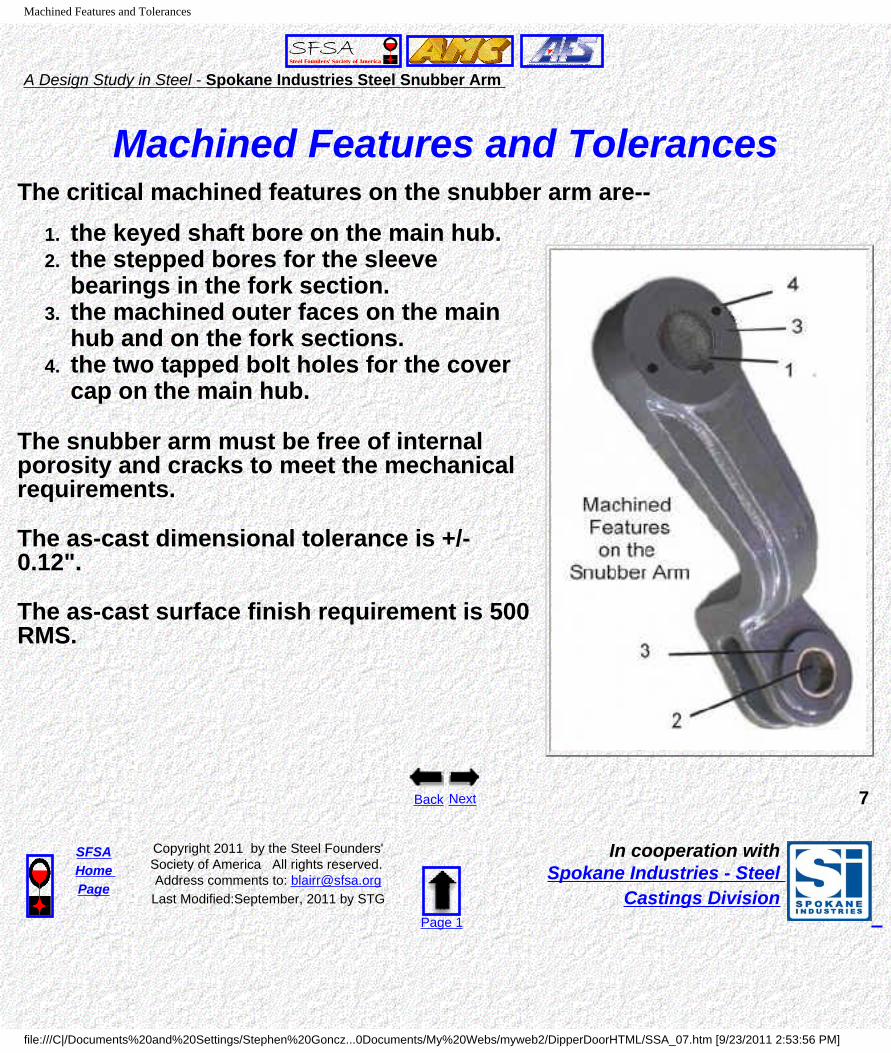
Machined Features and TolerancesThe critical machined features on the snubber arm are--
1. the keyed shaft bore on the main hub. 2. the stepped bores for the sleeve
bearings in the fork section. 3. the machined outer faces on the main
hub and on the fork sections. 4. the two tapped bolt holes for the cover
cap on the main hub.
The snubber arm must be free of internal porosity and cracks to meet the mechanical requirements.
The as-cast dimensional tolerance is +/- 0.12".
The as-cast surface finish requirement is 500 RMS.
Back Next 7
SFSAHome Page
Copyright 2011 by the Steel Founders' Society of America All rights reserved. Address comments to: [email protected] Modified:September, 2011 by STG
Page 1
In cooperation with Spokane Industries - Steel
Castings Division
file:///C|/Documents%20and%20Settings/Stephen%20Goncz...0Documents/My%20Webs/myweb2/DipperDoorHTML/SSA_07.htm [9/23/2011 2:53:56 PM]

Casting Benefits
A Design Study in Steel - Spokane Industries Steel Snubber Arm
Casting Benefits
Metal casting is the most cost-effective forming method for the snubber arm, because of its
strength requirements, size, shape, and machined features.
1. Casting produces a near-net shape piece with a 15% reduction in weight and no brittle low strength sections or weak joints.
2. A cost comparison to the original fabrication approach gave a unit savings of 46% for the casting with a 40% reduction in machining time and costs.
Back Next 8
SFSAHome Page
Copyright 2011 by the Steel Founders' Society of America All rights reserved. Address comments to: [email protected]
Last Modified:August, 2011 by STGPage 1
In cooperation with Spokane Industries - Steel
Castings Division
file:///C|/Documents%20and%20Settings/Stephen%20Goncz...Documents/My%20Webs/myweb2/DipperDoorHTML/SSA_07A.htm [9/23/2011 2:54:01 PM]

Design Issues
A Design Study in Steel - Spokane Industries Steel Snubber Arm
The Casting Design Issues Spokane Industries Steel Casting Division worked closely with P&H
Mining to design and produce the snubber arm castings.The casting design team (the P&H Mining design engineers and the Spokane Industries casting engineers) focused on three imperatives.
-- Design for Performance-- Design for Production / Castability-- Design for Cost
Critical Casting Design Issues --The requirements for performance, casting production, and cost are closely interconnected. Three casting design issues played a major role in meeting the three design imperatives.
● Select a steel alloy that meets the mechanical requirements and reliably produces the casting in a sound condition.
● Select a molding method that produces the required dimensional tolerances and surface finish in a cost-effective manner.
● Develop a casting and mold design that produces flaw-free components at with an optimized production cost.
Back Next 9
SFSAHome Page
Copyright 2011 by the Steel Founders' Society of America All rights reserved. Address comments to: [email protected]
Last Modified:August, 2011 by STGPage 1
In cooperation with Spokane Industries - Steel
Castings Division
file:///C|/Documents%20and%20Settings/Stephen%20Goncz...0Documents/My%20Webs/myweb2/DipperDoorHTML/SSA_08.htm [9/23/2011 2:54:04 PM]

Alloy Selection
A Design Study in Steel - Spokane Industries Steel Snubber Arm
Steel Alloy SelectionSpokane Industries casting engineers considered two Cr-Ni-Mo steel alloys for
the snubber arm - AISI 8620 and AISI 4320. Both of these alloys are used for moderate section sizes which require medium
hardenability, strength, and impact shock resistance.
AISI 8620 (0.18-0.23C, 0.70-0.90 Mn, 0.15-0.30 Si, 0.40-0.60Cr, 0.40-0.70 Ni, 0.15-0.25 Mo) AISI 4320 (0.17-0.22C, 0.45-0.65 Mn, 0.15-0.30 Si, 0.40-0.60Cr, 1.65-2.00 Ni, 0.20-0.30 Mo)
The mechanical properties of these two alloys depend on selecting a heat-treatment for the specified section thickness. With an appropriate heat-
treatment for the snubber arm the properties of the two alloys are --
AISI 8620 (HT A) AISI 4320 (HT B) Minimum Ultimate Tensile Strength 98 ksi 130 ksi Minimum Yield Strength 71 ksi 85 ksi Minimum % Elongation 21% 22%Minimum % Reduction in Area 54% 56%Impact Toughness (-40F) - ft-lbs 35 40 Brinell Hardness Range 270 BHN 255 BHN
The AISI 4320 meets all the mechanical property requirements goals and was the alloy chosen for casting the snubber arm.
Back Next 10
SFSAHome Page
Copyright 2011 by the Steel Founders' Society of America All rights reserved. Address comments to: [email protected]
Last Modified:August, 2011 by STGPage 1
In cooperation with Spokane Industries - Steel
Castings Division
file:///C|/Documents%20and%20Settings/Stephen%20Goncz...0Documents/My%20Webs/myweb2/DipperDoorHTML/SSA_09.htm [9/23/2011 2:54:07 PM]

Molding Method
A Design Study in Steel - Spokane Industries Steel Snubber Arm
Molding MethodOne of the first casting design decisions is the choice of a molding
method, which will determine the surface finish and the dimensional tolerances of the finished casting.
Spokane Industries casting engineers selected --
CHEMICALLY BONDED SAND MOLDINGIn this molding method, a mixture of fine sand and a urethane binder is packed around a wood or metal pattern in mold flasks. At room temperature, the sand- binder mixture becomes rigid. Pattern halves are removed and the mold is assembled with or without cores.
Chemically bonded sand was chosen as the most effective casting approach, based on the tolerance specifications, surface finish requirements, the moderate size and simple shape of
the casting, and the limited production run.
The following table lists the typical properties and characteristics of chemically bonded sand.
Target Chemical Bonded Sand
As-cast dimensions +/- tolerance across 4" 0.12" Typical 0.05"As-cast dimensions +/- tolerance across 33" 0.30" Typical 0.1"Nominal surface finish (RMS) 500 300-900Intricacy of Detail Fair GoodTool/Pattern Cost Low LowMold Material Cost ( Sand & Binder) Medium
Recovery Cost (Binder Burn-Out) Medium
Back Next 11
SFSAHome Page
Copyright 2011 by the Steel Founders' Society of America All rights reserved. Address comments to: [email protected]
Last Modified:August, 2011 by STGPage 1
In cooperation with Spokane Industries - Steel
Castings Division
file:///C|/Documents%20and%20Settings/Stephen%20Goncz...0Documents/My%20Webs/myweb2/DipperDoorHTML/SSA_10.htm [9/23/2011 2:54:10 PM]
Machining vs Cores
A Design Study in Steel - Spokane Industries Steel Snubber Arm
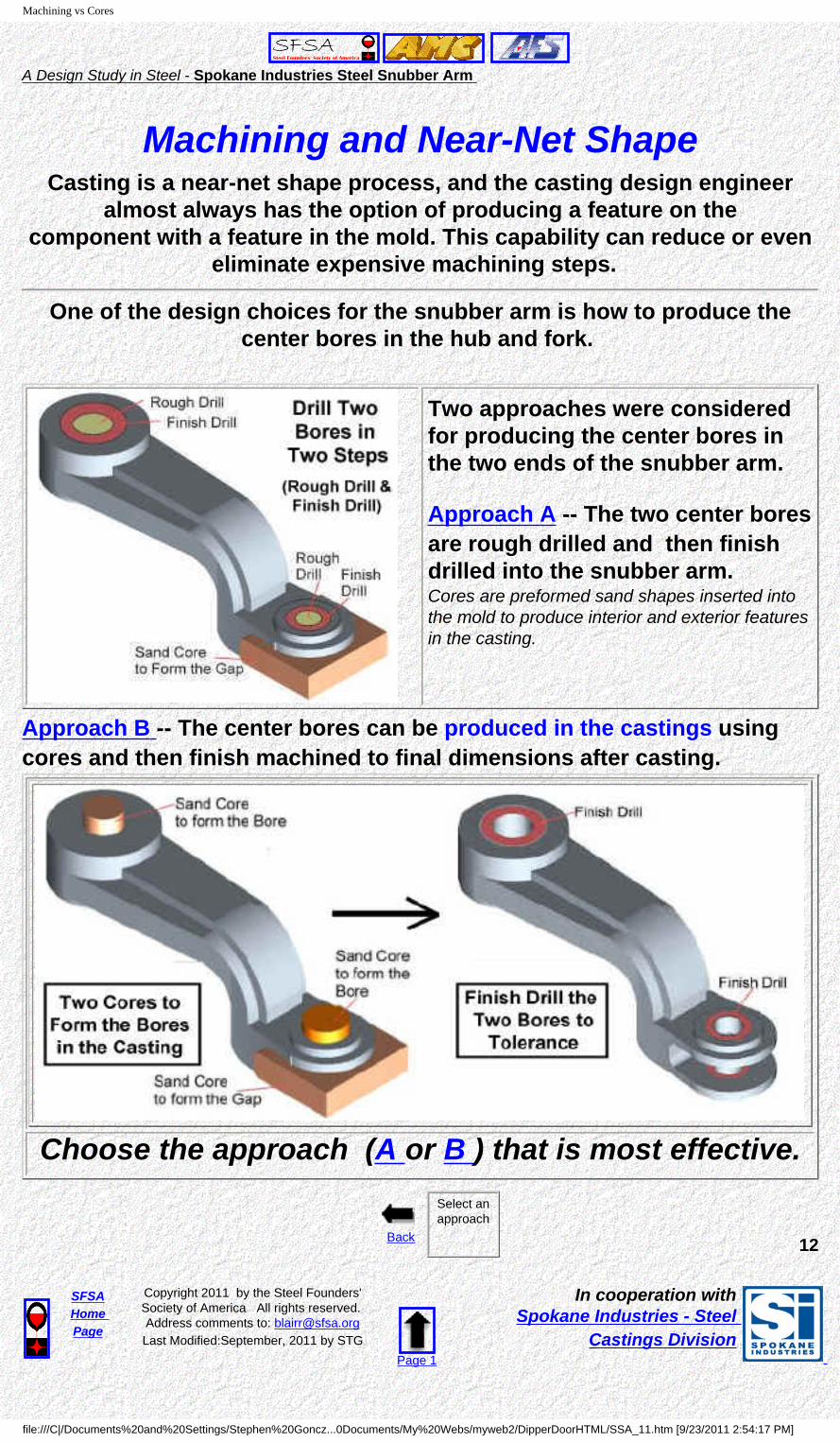
Machining and Near-Net ShapeCasting is a near-net shape process, and the casting design engineer
almost always has the option of producing a feature on the component with a feature in the mold. This capability can reduce or even
eliminate expensive machining steps.
One of the design choices for the snubber arm is how to produce the center bores in the hub and fork.
Two approaches were considered for producing the center bores in the two ends of the snubber arm.
Approach A -- The two center bores are rough drilled and then finish drilled into the snubber arm.Cores are preformed sand shapes inserted into the mold to produce interior and exterior features in the casting.
Approach B -- The center bores can be produced in the castings using cores and then finish machined to final dimensions after casting.
Choose the approach (A or B ) that is most effective.
Back
Select an approach
12
SFSAHome Page
Copyright 2011 by the Steel Founders' Society of America All rights reserved. Address comments to: [email protected] Modified:September, 2011 by STG
Page 1
In cooperation with Spokane Industries - Steel
Castings Division
file:///C|/Documents%20and%20Settings/Stephen%20Goncz...0Documents/My%20Webs/myweb2/DipperDoorHTML/SSA_11.htm [9/23/2011 2:54:17 PM]

2 Step Machining
A Design Study in Steel - Spokane Industries Steel Snubber Arm
Approach A -- Two-Step Machining of the Center Bores
Machining the center bores in the two sections will require both a rough drill and a finish drill machining operation.
The cost and time of the rough drilling these large diameter, deep bores in solid sections will be excessive.
Full machining (rough and finish) is not a cost-effective approach for the center bores.
Go back and select another approach.
Back 13
SFSAHome Page
Copyright 2011 by the Steel Founders' Society of America All rights reserved. Address comments to: [email protected]
Last Modified:August, 2011 by STGPage 1
In cooperation with Spokane Industries - Steel
Castings Division
file:///C|/Documents%20and%20Settings/Stephen%20Goncz...Documents/My%20Webs/myweb2/DipperDoorHTML/SSA_11a.htm [9/23/2011 2:54:24 PM]

Cores
A Design Study in Steel - Spokane Industries Steel Snubber Arm
Approach B -- Sand Cores for the Center Bores
The near-net shape center bores in the hub and the forks of the snubber arm can be economically produced using sand cores to give subsize diameter starting bores. Those bores are then quickly and easily finished machined to the final dimensions.
This will save significant machining costs and time, compared to a two-step (rough and finish) machining.
Using cores for the center bores is a cost-effective approach in this casting.
Go on to the next design issue.
Back Next 14
SFSAHome Page
Copyright 2011 by the Steel Founders' Society of America All rights reserved. Address comments to: [email protected]
Last Modified:August, 2011 by STGPage 1
In cooperation with Spokane Industries - Steel
Castings Division
file:///C|/Documents%20and%20Settings/Stephen%20Goncz...Documents/My%20Webs/myweb2/DipperDoorHTML/SSA_11b.htm [9/23/2011 2:54:31 PM]

Orientation in the Mold
A Design Study in Steel - Spokane Industries Steel Snubber Arm
Orientation in the MoldIn mold design, the orientation of the part in the mold is an important factor in producing a sound casting.
The part should be oriented in the mold, so that:
● The parting line (where the top and bottom molds fit together) is straight and horizontal.
● Metal flow is uniform with no drops in the different sections of the casting.
● The cores can be securely positioned in the mold.
The foundry engineer has two options for orienting the arm in the mold
● Option A - Edge Orientation● Option B - Horizontal Orientation
Which orientation will produce a straight parting line, uniform metal flow and and the most secure core positions?
Edge or Horizontal?
Back
Choose an Orientation 15
SFSAHome Page
Copyright 2011 by the Steel Founders' Society of America All rights reserved. Address comments to: [email protected] Modified:September, 2011 by STG
Page 1
In cooperation with Spokane Industries - Steel
Castings Division
file:///C|/Documents%20and%20Settings/Stephen%20Goncz...0Documents/My%20Webs/myweb2/DipperDoorHTML/SSA_12.htm [9/23/2011 2:54:34 PM]
Edge Orientation
A Design Study in Steel - Spokane Industries Steel Snubber Arm
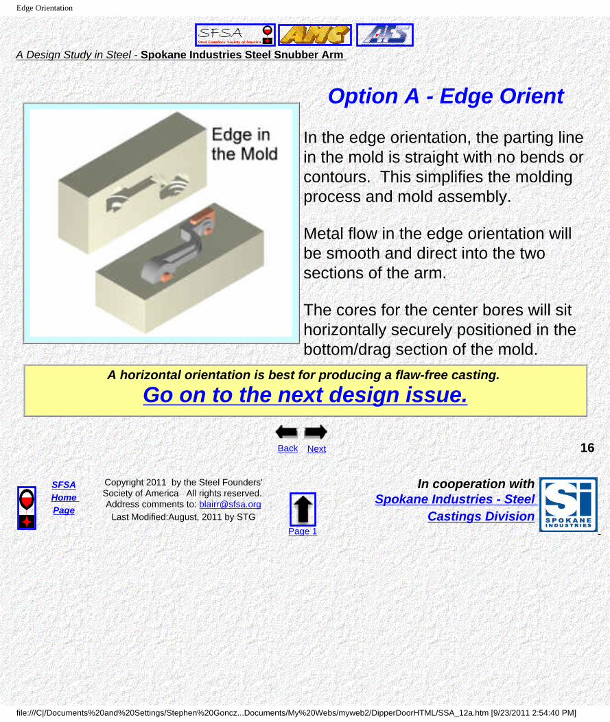
Option A - Edge Orient
In the edge orientation, the parting line in the mold is straight with no bends or contours. This simplifies the molding process and mold assembly.
Metal flow in the edge orientation will be smooth and direct into the two sections of the arm.
The cores for the center bores will sit horizontally securely positioned in the bottom/drag section of the mold.
A horizontal orientation is best for producing a flaw-free casting.
Go on to the next design issue.
Back Next 16
SFSAHome Page
Copyright 2011 by the Steel Founders' Society of America All rights reserved. Address comments to: [email protected]
Last Modified:August, 2011 by STGPage 1
In cooperation with Spokane Industries - Steel
Castings Division
file:///C|/Documents%20and%20Settings/Stephen%20Goncz...Documents/My%20Webs/myweb2/DipperDoorHTML/SSA_12a.htm [9/23/2011 2:54:40 PM]
Horizontal Orientation
A Design Study in Steel - Spokane Industries Steel Snubber Arm
Option B -- Horizontal
In the horizontal orientation, the mold parting line has to bend to follow the contour of the component in the horizontal orientation. This is added complexity in the mold fabrication and assembly process.
Metal flow will be complex and uneven, having to rise through the full height of the vertical step in the component.
The cores for the center bores will be oriented vertically with alignment issues between the top and bottom sections of the mold.
The vertical orientation is not a good approach for producing a flaw-free casting.
Go back and select another approach.
Back 17
SFSAHome Page
Copyright 2011 by the Steel Founders' Society of America All rights reserved. Address comments to: [email protected]
Last Modified:August, 2011 by STGPage 1
In cooperation with Spokane Industries - Steel
Castings Division
file:///C|/Documents%20and%20Settings/Stephen%20Goncz...Documents/My%20Webs/myweb2/DipperDoorHTML/SSA_12b.htm [9/23/2011 2:54:47 PM]

Two-On Mold Design
A Design Study in Steel - Spokane Industries Steel Snubber Arm
Mold ConfigurationWith the edge orientation of the snubber arm, the mold was configured
as a "two-on" mold with two snubber arms produced in each mold .
The figure to the right shows the basic design of the two-on mold.
The mold uses a center gate to feed the molten metal into the two castings.
The mold size is 42" x 48" with a drag depth of 8" and a cope height of 12".
Back Next 18
SFSAHome Page
Copyright 2011 by the Steel Founders' Society of America All rights reserved. Address comments to: [email protected]
Last Modified:August, 2011 by STGPage 1
In cooperation with Spokane Industries - Steel
Castings Division
file:///C|/Documents%20and%20Settings/Stephen%20Goncz...Documents/My%20Webs/myweb2/DipperDoorHTML/SSA_12C.htm [9/23/2011 2:54:56 PM]

Directional Solidification
A Design Study in Steel - Spokane Industries Steel Snubber Arm
Controlling Solidification in the CastingWhen metal solidifies, it shrinks in volume from the molten state.
It is common casting practice to use a "riser" as a reservoir of molten metal . The risers act as "back fills" which feed molten metal into the casting as it shrinks during solidification.
● A riser, being the last section to solidify, acts as a "trap" for the solidification shrinkage.
Risers are commonly positioned to feed into the sections of a casting which will be the last sections to solidify. In that position the risers
promote "directional solidification".● Directional solidification is defined as the process in which the casting -- "cools and
solidifies progressively from thin sections to heavy sections with constant metal feed into the heavy sections."
Back Next 19
SFSAHome Page
Copyright 2011 by the Steel Founders' Society of America All rights reserved. Address comments to: [email protected]
Last Modified:August, 2011 by STGPage 1
In cooperation with Spokane Industries - Steel
Castings Division
file:///C|/Documents%20and%20Settings/Stephen%20Goncz...0Documents/My%20Webs/myweb2/DipperDoorHTML/SSA_13.htm [9/23/2011 2:54:59 PM]

Riser Design
A Design Study in Steel - Spokane Industries Steel Snubber Arm
Riser Design
Design A - Four Risers Design B - Center Pour Cavity
The positioning and size of the riser/s plays a key role in controlling solidification in the casting.
Two riser designs were considered for the snubber arm:● Design A -- A center pour sprue with four risers feeding into the hub and
fork sections.● Design B -- A large diameter pour cavity in the center of the mold that acts
as the main riser. Choose the riser design which will be more effective in producing directional
solidification in the body of the casting.(Design A or Design B)
Back
Select a design
20
SFSAHome Page
Copyright 2011 by the Steel Founders' Society of America All rights reserved. Address comments to: [email protected] Modified:September, 2011 by STG
Page 1
In cooperation with Spokane Industries - Steel
Castings Division
file:///C|/Documents%20and%20Settings/Stephen%20Goncz...0Documents/My%20Webs/myweb2/DipperDoorHTML/SSA_14.htm [9/23/2011 2:55:02 PM]

Riser A
A Design Study in Steel - Spokane Industries Steel Snubber Arm
Design A -- Four Risers on the Hubs and Forks
The hub and fork sections on the two ends of the snubber arm are not major thermal masses. Solidification will naturally start at those two ends and then progress inwards to the center of the bar section.
Risers on the two far sections would not be feeding into the heavier center section and would work against the natural directional solidification.
Risers on the two end sections are not a good approach for producing directional solidification in the casting.
Go back and select another approach.
Back 21
SFSAHome Page
Copyright 2011 by the Steel Founders' Society of America All rights reserved. Address comments to: [email protected]
Last Modified:August, 2011 by STGPage 1
In cooperation with Spokane Industries - Steel
Castings Division
file:///C|/Documents%20and%20Settings/Stephen%20Goncz...Documents/My%20Webs/myweb2/DipperDoorHTML/SSA_14a.htm [9/23/2011 2:55:07 PM]

Riser B
A Design Study in Steel - Spokane Industries Steel Snubber Arm
Design B -- Center pour cavity The hub and fork sections on the two ends of the snubber arm are not major thermal masses, because of their large center bores.
Solidification will naturally start at those two ends and then progress inwards to the center of the heavy bar section.
The diameter of the center pour cavity can be expanded to act as a riser that feeds into the heavy bar section and promotes the natural directional solidification.
● The pour cavity is 10" in diameter and 10" high.
Solidification modeling confirmed that a center riser gave the the best solidification. (A video (Avi file) of a filling and cooling model for the snubber arm casting).
A center riser/ pour cavity is best location for producing directional solidification.
Go on to the next design issue.
Back Next 22
SFSAHome Page
Copyright 2011 by the Steel Founders' Society of America All rights reserved. Address comments to: [email protected]
Last Modified:August, 2011 by STGPage 1
In cooperation with Spokane Industries - Steel
Castings Division
file:///C|/Documents%20and%20Settings/Stephen%20Goncz...Documents/My%20Webs/myweb2/DipperDoorHTML/SSA_14b.htm [9/23/2011 2:55:18 PM]

Tie Rods
A Design Study in Steel - Spokane Industries Steel Snubber Arm
First Article CastingIt is common practice to do a "first article" test casting to confirm that
the mold design and the production parameters produce a casting that is flaw free and meets dimensional requirements.
A first article casting of the snubber arm showed that there was some warpage in the offset section of the arm that occurred during cooling.
The solution to this was to add "tie rods" between the ends of the two castings in the mold, as shown in the drawing.
These "tie rods" constrained the two castings during cooling and prevented the warpage that was seen in the first article.
Back Next 23
SFSAHome Page
Copyright 2011 by the Steel Founders' Society of America All rights reserved. Address comments to: [email protected] Modified:September, 2011 by STG
Page 1
In cooperation with Spokane Industries - Steel
Castings Division
file:///C|/Documents%20and%20Settings/Stephen%20Goncz...0Documents/My%20Webs/myweb2/DipperDoorHTML/SSA_15.htm [9/23/2011 2:55:23 PM]

Final Mold Design
A Design Study in Steel - Spokane Industries Steel Snubber Arm
Final Mold Design
Cope Pattern Drag Pattern
The photos show the top/cope pattern and the bottom/drag pattern used to make the sand molds.
● The sections shaded in red show the pouring basin, the gating into the center bars, and the tie rods between the two castings.
● The sections shaded in light tan show where the cores sit to form the center bores and the gap between the forks.
● The two yellow circles on the cope pattern show where the pour flask/riser sits in the assembled mold.
The two patterns are positioned in the metal flasks/frames. Then the pour flask (with a ceramic filter) is fitted onto the cope pattern. The top and bottom halves of the mold are formed by packing chemically bonded sand into the metal frames holding the patterns.
After the sand "cures" into a rigid body, the top and bottom mold sections are matched together "top-to bottom" to form a completed mold.
Back Next 24
SFSAHome Page
Copyright 2011 by the Steel Founders' Society of America All rights reserved. Address comments to: [email protected]
Last Modified:August, 2011 by STGPage 1
In cooperation with Spokane Industries - Steel
Castings Division
file:///C|/Documents%20and%20Settings/Stephen%20Goncz...0Documents/My%20Webs/myweb2/DipperDoorHTML/SSA_16.htm [9/23/2011 2:55:26 PM]

Casting Process
A Design Study in Steel - Spokane Industries Steel Snubber Arm
The Casting Process The snubber arms are cast in a three step process.
Metal Pouring into a Mold
1. The molten steel (~2900oF) is poured into the assembled sand mold and allowed to cool and solidify in the mold.
2. The solidified casting is removed from the mold, shot blasted to remove surface sand, and then given a normalizing (1650F) heat- treatment.
3. The gates and risers are torch cut off of the casting and the stubs are finish ground.
The casting is now ready for heat-treating.
Back Next 25
SFSAHome Page
Copyright 2011 by the Steel Founders' Society of America All rights reserved. Address comments to: [email protected]
Last Modified:August, 2011 by STGPage 1
In cooperation with Spokane Industries - Steel
Castings Division
file:///C|/Documents%20and%20Settings/Stephen%20Goncz...0Documents/My%20Webs/myweb2/DipperDoorHTML/SSA_17.htm [9/23/2011 2:55:30 PM]

Heat Treating
A Design Study in Steel - Spokane Industries Steel Snubber Arm
Heat Treating
Heat treatment of the snubber arms is a critical process step to produce the required microstructure, mechanical properties, and Charpy Impact values.
The snubber arm castings were heat treated with a 1700F austenization and water quench. They were then tempered at 1205F and water quenched.
Spokane Heat-Treat Furnace
Back Next 26
SFSAHome Page
Copyright 2011 by the Steel Founders' Society of America All rights reserved. Address comments to: [email protected] Modified:September, 2011 by STG
Page 1
In cooperation with Spokane Industries - Steel
Castings Division
file:///C|/Documents%20and%20Settings/Stephen%20Goncz...0Documents/My%20Webs/myweb2/DipperDoorHTML/SSA_18.htm [9/23/2011 2:55:33 PM]

Machining
A Design Study in Steel - Spokane Industries Steel Snubber Arm
Finish Machining
Four features are machined on each snubber arm.
1. The center bore in the hub is finished taper bored to the final dimensions. A key slot is cut into the center bore of the hub section.
2. The center bores in the forks are finished bored to the final dimensions with a step for a bearing seat.
3. The outer faces of the forks and the heavy hub are finish milled flat.
4. Two bolt holes (~1" diameter, 2" deep) are drilled and tapped into the main hub, for attaching a cover plate.
Snubber Arm Finish Machined.
Back Next 27
SFSAHome Page
Copyright 2011 by the Steel Founders' Society of America All rights reserved. Address comments to: [email protected]
Last Modified:August, 2011 by STGPage 1
In cooperation with Spokane Industries - Steel
Castings Division
file:///C|/Documents%20and%20Settings/Stephen%20Goncz...0Documents/My%20Webs/myweb2/DipperDoorHTML/SSA_19.htm [9/23/2011 2:55:36 PM]
Quality Assurance
A Design Study in Steel - Spokane Industries Steel Snubber Arm
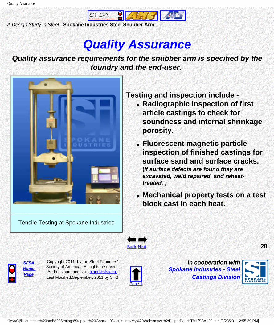
Quality AssuranceQuality assurance requirements for the snubber arm is specified by the
foundry and the end-user.
Tensile Testing at Spokane Industries
Testing and inspection include -
● Radiographic inspection of first article castings to check for soundness and internal shrinkage porosity.
● Fluorescent magnetic particle inspection of finished castings for surface sand and surface cracks. (If surface defects are found they are excavated, weld repaired, and reheat-treated. )
● Mechanical property tests on a test block cast in each heat.
Back Next 28
SFSAHome Page
Copyright 2011 by the Steel Founders' Society of America All rights reserved. Address comments to: [email protected] Modified:September, 2011 by STG
Page 1
In cooperation with Spokane Industries - Steel
Castings Division
file:///C|/Documents%20and%20Settings/Stephen%20Goncz...0Documents/My%20Webs/myweb2/DipperDoorHTML/SSA_20.htm [9/23/2011 2:55:39 PM]
Lessons Learned
A Design Study in Steel - Spokane Industries Steel Snubber Arm
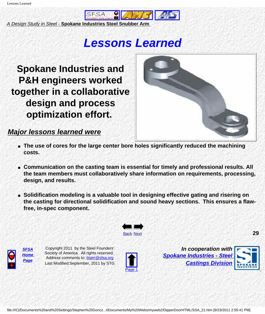
Lessons Learned
Spokane Industries and P&H engineers worked
together in a collaborative design and process optimization effort.
Major lessons learned were
■ The use of cores for the large center bore holes significantly reduced the machining costs.
■ Communication on the casting team is essential for timely and professional results. All the team members must collaboratively share information on requirements, processing, design, and results.
■ Solidification modeling is a valuable tool in designing effective gating and risering on the casting for directional solidification and sound heavy sections. This ensures a flaw-free, in-spec component.
Back Next 29
SFSAHome Page
Copyright 2011 by the Steel Founders' Society of America All rights reserved. Address comments to: [email protected] Modified:September, 2011 by STG
Page 1
In cooperation with Spokane Industries - Steel
Castings Division
file:///C|/Documents%20and%20Settings/Stephen%20Goncz...0Documents/My%20Webs/myweb2/DipperDoorHTML/SSA_21.htm [9/23/2011 2:55:41 PM]

Summary
A Design Study in Steel - Spokane Industries Steel Snubber Arm
Summary
Steel Snubber Arm on Mining Shovels
The steel snubber arm casting offers the following engineering and cost benefits.
● A near-net shape component with a 15% reduction in weight, reduced stress concentrations, integrated features, and no brittle low strength sections or weak joints.
● A unit savings of 46% for the casting with a 40% reduction in machining time and costs, compared to the original fabrication.
For further information on Spokane Industries steel castings, contact --Terry Decker -- Phone 509-921-8846
E-mail: [email protected] Web Site = www.spokaneindustries.com
Acknowledgment --The metalcasting design studies are a joint effort of the
Steel Founders' Society of America and the American Foundry Society.Project funding was provided by the American Metalcasting Consortium Project, which
is sponsored by the Defense Logistics Agency, Attn: DLSC-T, Ft. Belvoir, VA, 22060-6221
Back
The End 30
SFSAHome Page
Copyright 2011 by the Steel Founders' Society of America All rights reserved. Address comments to: [email protected] Modified:September, 2011 by STG
Page 1
In cooperation with Spokane Industries - Steel
Castings Division
file:///C|/Documents%20and%20Settings/Stephen%20Goncz...0Documents/My%20Webs/myweb2/DipperDoorHTML/SSA_22.htm [9/23/2011 2:55:44 PM]