Embed Size (px)
Citation preview

Title: On the effect of residual stresses on the transverse cracking in cross-ply carbon-polyetherimide laminates PhD-Thesis, University of Twente, The Netherlands April 2000
Author: L.L. Warnet ISBN: 90-36514223 Subjetcs headings: laminated composites, residual stresses, transverse cracking copyright © L.L. Warnet, 2000 Cover design G.C. Warnet printed by: Grafisch Centrum Twente, Enschede, The Netherlands

ON THE EFFECT OF RESIDUAL STRESSES ON THE TRANSVERSE CRACKING
IN CROSS-PLY CARBON-POLYETHERIMIDE LAMINATES
PROEFSCHRIFT
ter verkrijging van de graad van doctor aan de Universiteit Twente,
op gezag van de rector magnificus, prof.dr. F.A. van Vught,
volgens besluit van het College voor Promoties in het openbaar te verdedigen
op vrijdag 7 april 2000 te 13:15 uur.
door
Laurent Louis Warnet
geboren op 6 juni 1968 te Cambrai, Frankrijk

Dit proefschrift is goedgekeurd door de promotor
Prof. dr. ir. H. Tijdeman
en de assistant-promotor
Dr. P.E.Reed
Samenstelling promotiecomissie:
Prof. dr. ir. H.J. Grootenboer voorzitter
Prof. dr. ir. H. Tijdeman Universiteit Twente WB, promotor
Dr. P.E. Reed Universiteit Twente WB, assistant promotor
Prof. P. C. Powell Universiteit Twente WB
Prof. dr. ir. J.W.M. Noordermeer Universiteit Twente CT
Prof.dr. ir. R. Marissen TU Delft
Prof. J.R. White University of Newcastle (UK)

Excuse me, Sir ?


Summary Two themes form the basis of this study on fibre reinforced laminated composites: namely ‘thermal residual stress’ and ‘transverse cracking’. Thermal residual stresses are inherent to any composite structure and are internal stress within the structure that form during manufacture. Their formation arises from the difference in coefficient of thermal expansion of the fibre and the matrix. These stresses will act on both a fibre-matrix scale and on a ply-to-ply scale within a laminate. The presence of residual stress reduces the strength potential of composites. Transverse cracks are formed in laminates, which comprise plies of different fibre orientation. Transverse cracks run parallel to the fibres, through the thickness of an individual ply and are induced by a stress field acting transverse to the fibres. These cracks are recognised as being the first damage mechanism to occur in composite structures. Although the formation of transverse cracks is not generally directly responsible for the complete fracture of a composite structure, transverse cracks can serve to catalyse the development of further damage mechanisms. In certain composite systems, the level of thermal residual stress in a direction transverse to the fibres can approach the stress at which transverse cracking occurs. This is the case for the unidirectional carbon-fibre/polyetherimide system formed as a cross-ply laminate. The carbon-fibre/polyetherimide system combines a large difference in coefficient of thermal expansion between the fibre and the matrix with a large temperature differential during initial process cooling. This combination leads to large residual stresses in the laminate after its formation. The high level of residual stress that can be obtained with this system makes it ideal for the study of the effect of residual stresses on the formation of transverse cracking. This study investigates the role played by the residual stresses in the formation of transverse cracks in composite laminates. Limiting stress and energy release failure criteria are examined for the prediction of transverse crack formation in transversally loaded cross-ply carbon-fibre reinforced polyetherimide laminates The level of residual stress in the laminates considered is varied in different ways. The experimental and theoretical study concentrates initially on transverse crack formation in beam specimens under 3-point bending. A final section extends the study to the crack formation in point loaded laminate plates, where specimen edge effects are eliminated. The thesis is divided into 4 chapters, each representing a separate article dealing with a different aspect of the study.
In chapter 2, the quantification of the thermal residual stress on a macroscopic scale is reviewed. Particular attention is paid to the relaxation of these stresses with time after manufacture in a carbon-polyetherimide cross-ply laminate. Both experimental measurement and theoretical modelling of the residual stress relaxation of cross-ply carbon-polyetherimide laminates are reported. The modelled stress relaxation values are found to be significantly lower than those measured experimentally. This discrepancy is explained by the formation of transverse cracks during the experiments, which leads to an irreversible increase of the laminate compliance. The initiation of transverse cracks under only the presence of sufficient residual stress in the cross-ply laminate is confirmed by modelling of the stresses occurring in

the matrix around a fibre. It is shown that crazing can occur in regions of poor fibre-matrix interface, which could induce crack formation in regions of high fibre concentration.
In chapter 3, the formation of the first transverse crack in a cross-ply beams subjected to
bending is studied with varying levels of residual stress. The different levels of residual stress are obtained by using different laminate lay-ups. The measurement of the bending compliance before the occurrence of the first transverse crack shows that there exists a residual stress limit above which micro-cracking on a fibre-matrix occurs within the laminate before external loading is applied. The presence of these micro cracks induces the formation of the first transverse crack at lower applied loads. The applicability of a limiting stress criterion and an energy criterion to predict the onset of transverse crack formation is discussed.
The fourth chapter repeats the studies performed in the previous chapter, but now varying
the residual stress by changing the test temperature rather than varying the laminate lay-up. It is necessary to take account of the material property changes of the composite system at the different temperatures. Results of this further study reinforce the conclusions drawn from chapter 3.
Studies with beam specimens are simplified by being essentially a 2-dimensional problem,
but the presence of the beam edges can serve to affect transverse crack formation. Chapter 5 extends the investigation to the formation of transverse cracks in the same carbon-fibre/ polyetherimide laminates, but in transversally loaded plates, where crack formation is far removed from edge effects. Results show that the residual stresses present in the laminate are again sufficiently high to cause micro-damage, thus increasing the compliance of the system. The initiation of transverse cracks in plate and beam specimens cut from the same laminate is examined using a limiting stress criterion. The stress required for crack formation in the plate is always higher in the plate than in the equivalent beam specimen. This difference is attributed to the edge effects of the beam specimen, where cracks can initiate more easily.
It is concluded that • There is a large relaxation of the thermal residual stresses in the thermoplastic matrix,
carbon-fibre/polyetherimide laminate system after manufacture. This relaxation must be taken into consideration in any stress analysis seeking to predict the onset of transverse crack formation.
• The high residual stresses that can form in the laminates of carbon-fibre/polyetherimide are sufficient to induce micro-damage in the structure even before any external loading is applied. Weak interface adhesion between fibre and matrix serves to increase the chance of micro-damage occurring.
• Transverse cracks are formed in the cross-ply laminates under a combination of the thermal residual and externally applied stresses. A simple addition of these two terms in the application of a limiting stress criterion is inadequate to predict the onset of failure in the carbon-fibre/polyetherimide system. The micro-damage, which occurs under the action of the residual stress alone, induces micro-cracks, thus changing the properties of the material and rendering a limiting stress criterion inappropriate.
• Where the residual stress leads to micro-damage and micro-crack formation, a fracture mechanics approach to the prediction of composite failure may be more appropriate.
Table of contents Chapter 1: Introduction
1.1. General introduction ............................................................................................1 1.2. Transverse cracking .............................................................................................2 1.3. Thermal residual stresses .....................................................................................6 1.4. Outline of the thesis .............................................................................................7
Chapter 2: On the relaxation of thermal residual stresses and related
damage in carbon-polyetherimide laminates
2.1. Introduction........................................................................................................11 2.2. Thermo-mechanical properties ..........................................................................12
2.2.1. Constituents....................................................................................12 2.2.2: The prepreg and resulting composite layer....................................13
2.3. Evaluation of the thermal residual stress relaxation ..........................................14 2.3.1. The thermal residual stresses at the macroscopic level .................14 2.3.2. Micromechanics models ................................................................17 2.3.3. Evaluation of the stress relaxation .................................................18
2.4. Experimental evaluation of the relaxation .........................................................20 2.4.1. Measurement of the relaxation.......................................................20 2.4.2. Results............................................................................................22
2.5. On the formation of the transverse cracks .........................................................23 2.5.1. Model description ..........................................................................25 2.5.2. Results............................................................................................26
2.6. Conclusion .........................................................................................................31
Chapter 3: The effect of residual stress on transverse cracking in cross-ply
carbon-polyetherimide laminates under bending: Variation of the laminate lay-up
3.1. Introduction........................................................................................................35 3.2. Properties of the laminated composite ...............................................................36 3.3. Beam bend test analysis .....................................................................................37
3.3.1. Compliance ....................................................................................37 3.3.2. Thermal residual stresses ...............................................................39 3.3.3. Bending stress ................................................................................41 3.3.4. Energy released at crack formation................................................42
3.4. Experimental programme...................................................................................43 3.4.1. Specimen preparation.....................................................................43 3.4.2. Experimental set-up .......................................................................44

3.4.3. Results............................................................................................46 3.5. Discussion ..........................................................................................................53
3.5.1. Use of a Maximum Stress Criterion...............................................53 3.5.2. Fracture mechanics approach.........................................................56
3.6. Conclusions ........................................................................................................58
Chapter 4: The effect of thermal residual stress on transverse cracking in cross-ply polyetherimide-carbon laminates under bending: Variation of the test temperature
4.1. Introduction........................................................................................................61 4.2. Thermo-mechanical properties ..........................................................................62
4.2.1. Constituents....................................................................................62 4.2.2. The prepreg and resulting composite layer ....................................63
4.3. Beam bend test analysis .....................................................................................64 4.3.1. Compliance ....................................................................................64 4.3.2. Thermal residual stress ..................................................................65 4.3.3. The bending stress..........................................................................67
4.4. Experimental programme...................................................................................68 4.4.1. Specimen preparation.....................................................................68 4.4.2. Experimental set-up. ......................................................................69 4.4.3. Results............................................................................................72
4.5. Discussion ..........................................................................................................77 4.6. Conclusion .........................................................................................................79
Chapter 5: On the effect of thermal residual stresses on the transverse cracking of carbon-polyetherimide composite plates loaded transversally
5.1. Introduction........................................................................................................81 5.2. Experimental program. ......................................................................................82
5.2.1. Specimen preparation.....................................................................82 5.2.2. Beam bend test ...............................................................................86 5.2.3. Plate bend test ................................................................................91
5.3. Results ................................................................................................................94 5.3.1. Beam specimens.............................................................................94 5.3.2. Plate specimens..............................................................................97
5.4. Discussion ..........................................................................................................99 5.4.1. Effect of the beam edge quality .....................................................99 5.4.2. Effect of the through-thickness fibre distribution........................100
5.5. Conclusion .......................................................................................................103
Chapter 6: Concluding remarks
6.1. On the residual stress relaxation ......................................................................105 6.2. On the presence of residual stress induced micro-damage ..............................105 6.3. On the use of strength-based failure criteria ....................................................106 6.4. On the use of fracture mechanics.....................................................................106
Appendix:
A. E2 as a function of the curvature of a [90/0] laminate .......................................109 B. Shear deflection of composite beams.................................................................111


Chapter 1 1
Chapter 1
Introduction
1.1. General introduction Fibre-reinforced composite materials combine the characteristics of at least two components in order to obtain unique properties. For example, continuous fibre composites are known for their high specific stiffness and strength compared to steel and aluminium. The fibres are used for their high stiffness and strength primarily to reinforce the matrix material in which they are set. The matrix protects and binds the fibres together and transfers load between fibres. The wide range of available fibres and matrices and the different ways the two components can be combined make it possible to tailor a composite to a large range of applications. This also makes the description and the prediction of the mechanical behaviour of a composite very demanding. When considering the failure behaviour of a composite for example, the specificity of composites is reflected in the way they absorb energy. Although metals will absorb energy through elastic and plastic deformation, composites cannot undergo large plastic deformation and will absorb energy by creating multiple crack surfaces induced by different failure modes [1]. Prediction of the failure behaviour of any structure made from composites normally requires a thorough stress analysis. This requires taking the thermal residual stresses into consideration, in addition to the usual mechanically applied stresses due to the external loads, whichever analytical method is used. The residual stresses build up during fabrication of the composite as it is cooled from the melt temperature of the matrix to room temperature, thus fixing and embedding the fibres. Thermal residual stresses arise from differences in the coefficients of thermal expansion of the matrix and the fibre. The presence of residual stresses in the composite are known to reduce their apparent strength. These stresses are mostly taken into account in a stress analysis by simply adding them to the mechanically applied stresses. Other effects related to the residual stresses are less known. It has been suggested that the thermal residual stresses can cause the failure of fibre-matrix interfaces even before testing [2,3]. Combination of a few of these fibre-matrix debonds can lead to the formation of micro-cracks, which can in turn induce premature failure, particularly in a direction parallel to the fibres. Such failure mechanisms are difficult to observe and leave the question of their possible effect on the overall behaviour of the composite. Also the relaxation of the residual stress between the processing of the composite and its use can influence the quantification of these stresses. These changes need to be taken into consideration to accurately quantify the stresses in a mechanically loaded system, especially to determine the state of stress before the onset of failure.

2 Introduction
The present study addresses the problem of the influence of the level of residual stresses on the failure behaviour in composites. The failure behaviour studied was limited to a description of the stress required for the occurrence of the first fully-grown crack to initiate in cross-ply beams subjected to a three point bend test. In the experimental studies performed, the level of thermal stresses in the test specimens was varied through two routes. The most straightforward way was to test at different temperatures. The second approach used different cross-ply lay-ups to achieve different levels of residual stress while testing at one temperature. Using the three point bend test provides a simple two-dimensional plane strain situation as the basis for studying the transverse crack formation. Failure criteria observed under the beam loading conditions do not necessarily represent the more common situation of crack formation in plates. Hence the study was extended to consider transverse crack formation in point loaded laminated plates in bending, where cracks form in a three-dimensional stress field. The system selected for the studies was carbon-polyetherimide. This system has been considered for possible use in the aircraft industry, because of the toughness of the thermoplastic polyetherimide matrix. Previous studies [4] were available quantifying the residual stresses obtained in cross-ply laminates for this system. These had shown that the system provided a high level of residual stresses, which arose from the relatively high temperature at which the polyetherimide matrix set during the laminate manufacture. Hence the carbon-polyetherimide system provided (a) established data on the level of residual stresses , (b) a wide range of possible residual stresses to study their effect on transverse crack formation. Some important related principles will be shortly developed next and this introductory chapter is concluded by an outline of the thesis.
1.2. Transverse cracking The composites studied in this thesis are built up from layers of unidirectional fibres embedded in matrix and laminated at different angles. It is worth defining at this stage the scales at which the analysis of a composite might be considered. The smallest scale of consideration, called micro-scale, concerns the interaction between the fibre and the matrix. The quadrant of a single fibre with attached matrix, shown in figure 1.1-a, is assumed to be representative of the composite structure at that level of detail. Such micro-scale models can be used to study the relationship between the individual properties of fibre and matrix with that of the composite formed (termed micro-mechanics). For example, the properties of the composite layer made of continuous fibre oriented in one direction (figure 1.1-b) can be analysed using a micro-mechanics approach. The properties at the ply level (macro-scale) are mostly considered as average properties for each of the length, width or thickness directions, which are therefore assumed to be transversally isotropic. At this level, the properties and behaviour of an individual ply are considered without reference to the constituents at the micro-scale.
Chapter 1 3
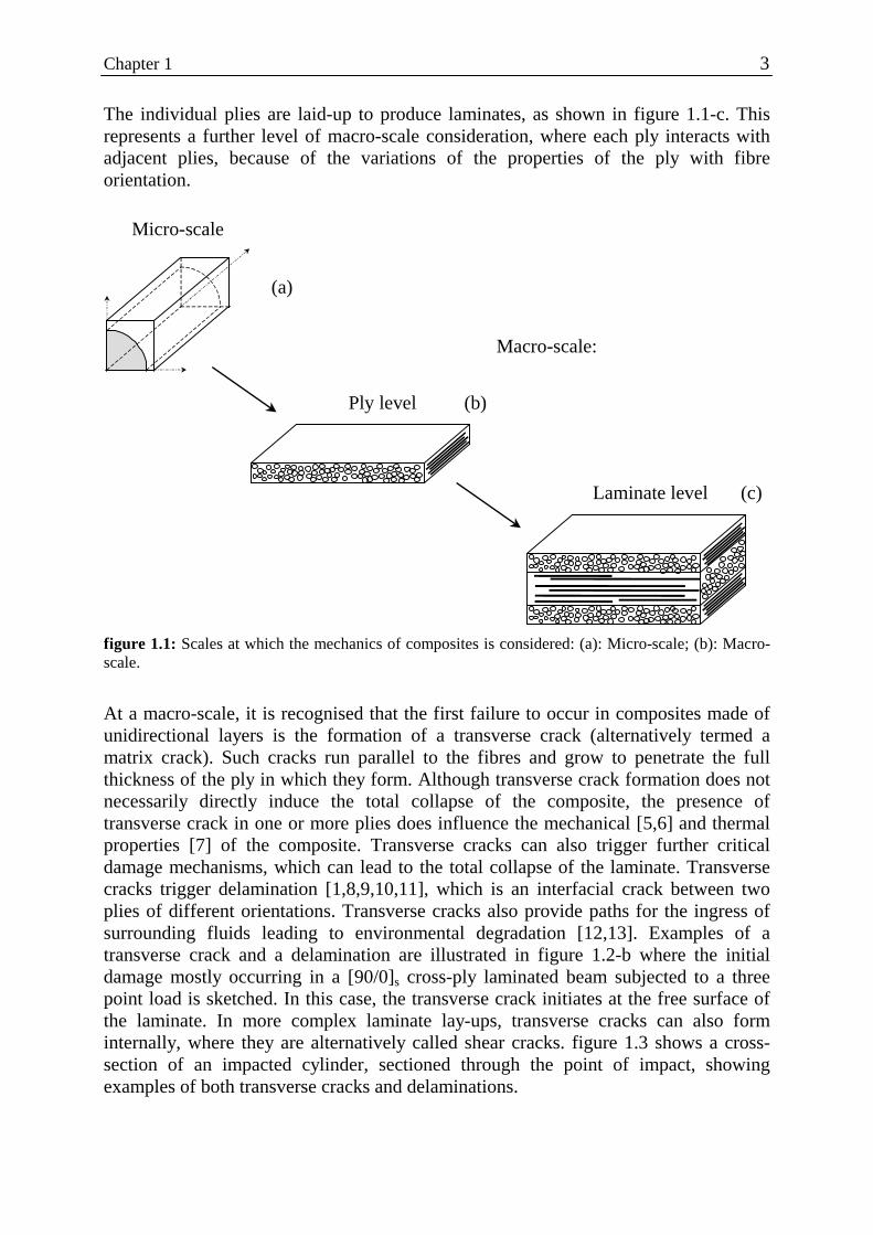
The individual plies are laid-up to produce laminates, as shown in figure 1.1-c. This represents a further level of macro-scale consideration, where each ply interacts with adjacent plies, because of the variations of the properties of the ply with fibre orientation.
Micro-scale
Macro-scale:
(a)
Ply level
Laminate level
(b)
(c)
figure 1.1: Scales at which the mechanics of composites is considered: (a): Micro-scale; (b): Macro-scale.
At a macro-scale, it is recognised that the first failure to occur in composites made of unidirectional layers is the formation of a transverse crack (alternatively termed a matrix crack). Such cracks run parallel to the fibres and grow to penetrate the full thickness of the ply in which they form. Although transverse crack formation does not necessarily directly induce the total collapse of the composite, the presence of transverse crack in one or more plies does influence the mechanical [5,6] and thermal properties [7] of the composite. Transverse cracks can also trigger further critical damage mechanisms, which can lead to the total collapse of the laminate. Transverse cracks trigger delamination [1,8,9,10,11], which is an interfacial crack between two plies of different orientations. Transverse cracks also provide paths for the ingress of surrounding fluids leading to environmental degradation [12,13]. Examples of a transverse crack and a delamination are illustrated in figure 1.2-b where the initial damage mostly occurring in a [90/0]s cross-ply laminated beam subjected to a three point load is sketched. In this case, the transverse crack initiates at the free surface of the laminate. In more complex laminate lay-ups, transverse cracks can also form internally, where they are alternatively called shear cracks. figure 1.3 shows a cross-section of an impacted cylinder, sectioned through the point of impact, showing examples of both transverse cracks and delaminations.

4 Introduction
Transverse crack Delamination
90o
90o
0o
y
zx
(a) (b) figure 1.2: (a): Three point bend test of a [90/0]s laminated beam. (b): Close-up showing a transverse
and a delamination.
The origin of transverse cracking lies in the composite behaviour at the fibre-matrix interface, when it is loaded transverse to the fibre direction. Conditions for transverse crack formation need to be considered at the micro-scale level, and several authors [14,15,16] have analysed the conditions at which interface failure may occur. These studies are concerned with crack formation both far from the free edge of the specimen [14] and at the free edges [15,16]. In the latter situation, stress singularities occur at the free edge of the fibre. Failure tends to initiate at the free edge of a finite width specimen, because of the stress situation at this position. Transverse crack formation is then the result of propagation from an inherent flaw or the coalescence of micro-cracks generated at the fibre-matrix interface.
figure 1.3: Cross-section of an impacted composite tube illustrating
transverse cracks and delaminations.
Early work on transverse cracking was performed on cross-ply laminated specimens loaded in tension. Much work has been done in characterising and predicting transverse cracking in tensile specimens. Some authors have based the modelling of the influence of transverse cracks on the stiffness of the specimen on shear-lag analysis [5,17,18,19]. Others have used variational mechanics for the same purpose [20,21,22]. The failure criteria used can be ranged into two categories: strength-based models [18,23,24], or energy release rate-based models [17,21,22,25,26]. A disadvantage of the strength of material approach is that the stress at the occurrence of the transverse cracks is dependent on the lay-up used as well as on the ply thickness [17,18]. The strength of the unidirectional laminate used in this method cannot be used as a basic material property [27,28]. An overview of different analytical methods, as well as the possible failure criteria was presented and evaluated by Nairn, Hu and Barck [28].

Chapter 1 5
They concluded that the only satisfactory analysis able to describe the behaviour of the various range of lay-ups is the one that uses variational analysis in combination with an energy-release-rate failure criterion. The situation in a laminate subjected to bending is different to that in a tensile specimen. The stresses in the cross-section of a tensile specimen are constant over its length. The probability that a large defect exists along the length to initiate the first transverse crack is therefore relatively high. In a beam loaded under three point bend, the stresses vary along the length of the beam and are only maximum over a limited volume of the composite. Compared to the tensile specimen, the probability that the first transverse crack is initiated by a large defect in this region is therefore lower. This is illustrated by comparing the stresses at the occurrence of the first transverse crack in a unidirectional laminate when tested under the two different conditions. The results obtained with a tensile specimen can be half the value obtained under bending [29,30]. The term “first transverse crack” is therefore not used in tensile tests, where one prefers predicting the crack density as a function of the applied load. The present study concentrates on the macroscopic formation of the first transverse crack. For the reason outlined above, it was chosen to test beams under quasi-static three point bend conditions. The lay-up adopted was chosen to facilitate the observation of the transverse crack formation. Hence, the layer in which the transverse crack would occur was placed at the free surface, where the bending stress is maximum. Beside the fact that it becomes easy to detect visually, the formation of transverse crack in a [90/0]s lay-up under bending will lead to a clear increase in compliance of the beam, when compared to that of [0/90]s. An increase in compliance at the formation of the crack also eases the use of an energy release rate-based method. An advantage of using a finite width beam for the test specimen, lies in the relative simplicity of analysis when considering the problem on a macroscopic scale. A disadvantage, however, is that failure may occur at the edges of the specimen. The conclusions drawn on the basis of beam testing therefore need to be confirmed on a different test specimen geometry where failure will not initiate from the edges. A centrally, transversally loaded square plate geometry was adopted for this purpose.
The occurrence of the first transverse crack is characterised in this thesis by the corresponding stress for its formation. This stress can be used in a simple strength-based failure criterion. Such criteria are semi-empirical and are used here as a basis for discussion on the effects of the level of residual stress on the conditions for transverse crack formation. An energy release rate method is also developed in one of the chapters.

6 Introduction
1.3. Thermal residual stresses The difference in coefficients of thermal expansion of the fibre and matrix combined with the temperature step during the fabrication of the composite, causes complex mechanisms of differential shrinkage in the composite. This results in thermal residual stresses, which are not insignificant and must be taken into account in any stress analysis of the composite structure. There are various ways in which the residual stresses can influence the behaviour of a composite. Here again, it is possible to consider the residual stresses either on a micro or macro-scale. When considering a fibre embedded in a matrix in the single fibre situation, the temperature change on cooling from the melt or solidification temperature of the matrix to room temperature, leads to shrinkage of the matrix onto the fibre. This enhances the adhesion of the matrix on the fibre by increasing the Van der Waals forces reducing the distances between the atoms of matrix and fibre. In the case of a thermoplastic matrix, this partly compensates for the absence of chemical primary bonds at the fibre-matrix interface [31]. A different situation exists at the free end of a fibre. Due to the biaxial contraction of the matrix on cooling, tensile radial stress occurs at the fibre-matrix interface near the fibre ends. This will therefore contribute to the formation of micro-cracks at the fibre-matrix interface in the region of fibre ends [16,32]. In the case of a multi-layer laminate, the constraints induced by the adjacent layer will locally change the stress situation at the fibre-matrix interface. This can lead to radial tensile stresses at the fibre-matrix interface. On a macroscopic scale, the coefficient of thermal expansion of a ply is dependent on its orientation. Thermal residual stresses will therefore also build up on a ply-to-ply basis in a laminate built-up from layers with different orientation. The level of residual stresses reached with certain lay-ups and material combinations can be critical for the integrity of the composite. As an example, the level of residual stresses in the 90° layer of a cross-ply carbon-polyetherimide laminate can be of the same sort of order as the experimentally determined tensile strength of a uniaxial 90° laminate [33 (chapter 3 of this thesis)]. This means that failure would be expected to occur soon after any further mechanical stress is applied. In order to provide a large range of thermal residual stresses for this study, a thermoplastic matrix was used, which had a high processing temperature. This provided a large temperature differential during cooling and hence higher residual stresses at the test temperature. The polyetherimide chosen is amorphous, thus avoiding the necessity to take volumetric changes due to crystallisation into consideration for residual stress determination. Carbon fibre has a negative coefficient of thermal expansion longitudinally, this provides the highest differential shrinkage between fibre and matrix, which also contributes to the formation of high residual stresses. Eijpe [4] described the measurement of the residual stresses of the carbon-polyetherimide system after fabrication in detail. The further important factor of residual stress relaxation between fabrication and testing will be measured and analysed in this thesis.

Chapter 1 7
1.4. Outline of the thesis This thesis contains four main chapters. The work has been prepared as a series of papers, ready for immediate publication in journals, with each chapter forming one independent paper. This leads to a requirement of some review of the previous ‘publication’ in certain chapters. The author apologises for any inconvenience caused by this way of presenting the thesis, with the consequent repetition of some essential details in different chapters. The second chapter considers the quantification of the thermal residual stresses on a macroscopic scale, in particular focusing on the relaxation of the ply-to-ply residual stresses in a thermoplastic matrix cross-ply laminate. The measurements are based on a method for measuring the residual stresses described by Nairn and Zoller [34]. The formation of transverse cracks induced by the residual stresses is reported. A micro-scale model is developed, analysing the situation in the matrix near the fibre-matrix interface, due to the residual stresses, which supports the observation made during the experiments. The third chapter investigates the effect of the level of residual stresses on the failure stress at the occurrence of the first transverse crack in a loaded structure. Cross-ply beam specimens, with the 90° layer at the free surface, were subjected to three point bend testing and loaded until the first transverse crack occurred. The level of ply-to-ply thermal stresses was varied through the use of different lay-ups of the beams tested. Although the thickness of the outer 90° layer was kept constant, the composition of the central 0° layer was varied both in thickness and in the type of fibre used. All the investigations in this section were conducted at one test temperature (23°C). Both stress and energy types of failure analyses were applied. This study shows that there exists a residual stress level above which micro-damage is induced. Development of micro-damage reduces both the stiffness of the composite and the stress for the occurrence of the first transverse crack. The aim of the fourth chapter is similar to that of the third chapter, as it investigates the influence of the residual stresses on the occurrence of the first transverse crack. However, in this section, the level of residual stress is varied by changing the test temperature and keeping the composite lay-up constant. The properties of the constituents of the composite at the different temperatures play a key role in this case. The conclusions drawn in this chapter confirm those obtained in chapter 3, for the critical residual stress level for micro-damage and the relative reduction of stress measured at fracture, as the residual stress increases. In the fifth chapter, further checks are made that the conclusions drawn from tests on beam specimens are not specific to this geometry. Damage initiates at the free-edges of the three point bend specimens. Hence the possible effects of the different state of stress at the edges on crack formation was examined. The investigations are extended to crack formation in square plates loaded transversally and centrally, where cracks initiate in the body of the specimen, far removed from any possible edge.

8 Introduction
References
1. Cantwell, W.J., Morton, J.; “The impact resistance of composite materials - A review”;
Composites, Vol. 22 (1991), p. 347-362. 2. Morris, W.L., Inman, R.V., Cox, B.N.; “Microscopic deformation in a heated unidirectional
graphite-epoxy composite”; J. of Materials Science, Vol.24 (1989), p. 199-204. 3. Abedian, A., Szyszkowski, W.; “Influence of the free surface on the thermal stresses in
unidirectional composites”; Composites Part A, Vol. 28A (1997), p. 573-579. 4. Eijpe, M.P.I.M.; “A modified layer removal method for determination of residual stresses in
Polymeric composites”; PhD Thesis, University of Twente (NL), ISBN 9036510155 (1997). 5. Highsmith, A.L., Reifsnider, K.L.; “Stiffness-reduction mechanisms in composite laminates”;
Damage in Composite Materials, ASTM STP 775, Reifsnider, K. L., Ed., 1982, pp. 103-117. 6. Smith, P.A., Wood, J.R.; “Poisson’s ratio as a damage parameter in the static tensile loading
of simple crossply laminates”; Composites Science and Technology, Vol.38 (1990), p. 85-93. 7. Adams, D.S., Herakovitch, C.T.; “Influence of damage on the thermal response of graphite-
epoxy laminates”; J. of Thermal Stresses, Vol. 7 (1984), p.91-103. 8. Crossman, F.W., Wang, A.S.D.; “The dependence of transverse cracking and delamination
on ply thickness in graphite/epoxy laminates”; Damage in Composite Materials, ASTM STP775, Reifsnider, K. L., Ed, 1982, pp. 118.
9. Nairn, J.A., Hu, S.; “The initiation and growth of delaminations induced by matrix microcracks in laminated composites”; Int. J. of Fracture, Vol. 57 (1992), p. 1-24.
10. Liu, S.; “Delamination and matrix cracking of cross-ply laminates due to a spherical indenter”; Composite structures, Vol. 25 (1993), p. 257-265.
11. Lammerant, L., Verpoest, I.; “The interaction between matrix cracks and delaminations during quasi-static impact of composites”; Composites Science & Technology, Vol. 51 (1994), p.505-516.
12. Amer, M.S., Koczak, M.J., Schadler, L.S.; “Relating hydrothermal degradation in single fibre composites to degradation behaviour in bulk composites”; Composites Part A, Vol.27A (1996), p.861-867.
13. Clifton Furrow, A.P., Dillrad, D.A., Clair, T.L., Hinkley, J.; “Dye penetrant induced microcracking in high performance thermoplastic Polyimide composites”; J. of Composite Materials, Vol. 32 (1998), p. 31-48.
14. Ishikawa, T.; “Strengths and thermal residual stresses of unidirectional composites”; J. of Composite Materials, Vol. 16 (1982), p.40-52.
15. Szyszkowski, W., King, J.; “Stress concentrations due to thermal loads in composite materials”; Computers and structures, Vol.56 (1995), p. 345-355.
16. Morris, W.L, Inman, R.V., Cox, B.N.; “Microscopic deformation in a heated unidirectional graphite-epoxy composite”; J. of Materials Science, Vol.24 (1989), p. 199-204.
17. Parvizy, A., Garrett, K.W., Bailey, J.E.; “Constrained cracking in glass fibre-reinforced epoxy cross-ply laminates”; Journal of Materials Science, Vol. 13 (1978), p. 195-201.
18. Peters, P.W.M.; “The strength distribution of 90o plies in 0/90/0 graphite-epoxy laminates”; J. of Composites Materials, Vol. 18 (1984), p. 545-556.
19. Flaggs, D.L.; “Prediction of tensile matrix failure in composite laminates”; J. of Composite Materials, Vol. 19 (1985), p. 29-50.
20. Hashin, Z.; “Analysis of stiffness reduction of cracked cross-ply laminates”; Engineering Fracture Mechanics, Vol. 25 (1986), p. 771-778.
21. Liu, S., Nairn, J.A.; “The formation and propagation of matrix microcracks in cross-ply laminates during static loading”; J. of Reinforced Plastics and Composites, Vol.11 (1992), p. 158-178.
22. Gillespie Jr, J.W., Hansen, U.; “Transverse cracking of composite laminates with interleaves: a variational approach”; J. of Reinforced Plastics and Composites, Vol. 16 (1997), p. 1066-1092.
23. Garrett, K.W., Bailey, J.E.; “Multiple transverse fracture in 90o cross-ply laminates of a glass fibre-reinforced polyester”; J. of Material Science, Vol. 12 (1977), p. 157-168.

Chapter 1 9
24. Reddy, J.N., Pandey, A.K.; “A first-ply failure analysis of composite laminates”; Computers &
Structures, Vol. 25 (1987), p. 371-393. 25. Laws, N., Dvorak, G.J.; “Progressive transverse cracking in composite laminates”; J. of
Composite Materials, Vol. 22 (1988), p. 900-916. 26. Boniface, L., Ogin, S.L., Smith, P.A.; “Strain energy release rates and the fatigue growth of
matrix cracks in model arrays in composite laminates”, Proc.Royal Society London A, Vol. 432 (1991), p.427-444.
27. Flaggs, D.L., Kural, M.H.; “Experimental determination of the in situ transverse lamina strength in graphite/epoxy laminates”; J. of Composite Materials, Vol. 16 (1982), p. 103-116.
28. Nairn, J.A., Hu, S., Bark, J.S.; “A critical evaluation of theories for predicting microcracking in composite laminates”; J. of Materials Science, Vol. 28 (1993), p. 5099-5011.
29. Klug, T.H., Reichert, J., Brückner, R.; ”Contribution to the problem of tensile and bending-test method for SiC-fibre-reinforced glass”; J. of Materials Science; Vol. 28 (1993), p. 6303-6306.
30. Lammerant, L.; “De interaktie van matrixscheuren en delaminaties bij impakt van komposietmaterialen”; P.H.D Thesis K.U. Leuven (1995)
31. Pegoraro, M., Di Landro, L.; “Influence of components and interface conditions on mechanical properties of composites and blends”; Makromolekulare Chemie, Macromolecular Symposia, Vol. 70/71 (1993), p. 193-212.
32. Abedian, A., Szyszkowski, W.; “Influence of the free surface on the thermal stresses in unidirectional composites”; Composites Part A, Vol. 28A (1997), p. 573-579
33. Warnet, L., Reed, P.E., Akkerman, R; “The effect of residual stress on transverse cracking in cross-ply Carbon-Polyetherimide laminates under bending: Variation of the laminate lay-up”; prepared for publication.
34. Nairn, J.A., Zoller, P.; “The development of residual thermal stresses in amorphous and semicrystalline thermoplastic matrix composites.”; Toughened Composites, ASTM STP 937, Johnston, N.J., Ed. (1987), p. 328-341.

10 On the relaxation of thermal residual stresses

Chapter 2 11
Chapter 2
On the relaxation of thermal residual stresses and related damage in carbon-polyetherimide laminates
2.1. Introduction Thermal residual stresses are inherent to fibre reinforced composites and are influenced by the respective thermo-mechanical properties of their two constituents. They build up when the laminate cools down from the processing temperature to room temperature. Residual stresses will be present on a fibre-matrix scale (micro-scale), where for example the contraction of the matrix on the fibre can enhance the fibre-matrix adhesion [1]. When considering a composite laminate built up from layers having different orientations, the residual stresses will also be present on a ply-to-ply scale (macro-scale). In contrast to the micro-stresses, these macro-stresses are relatively easy to quantify experimentally. Worth mentioning are the methods for determining the residual stresses at the macro-scale, involving the measurement of the curvature of non-symmetric laminate developed by Nairn and Zoller [2], and the modified layer removal method developed by Eijpe [3] resulting in a stress profile over the whole thickness. Polymeric matrices, especially thermoplastics, are viscoelastic. Viscoelasticity can therefore be important in a ply of a laminate in the direction perpendicular to the fibres, where the properties are dominated by the matrix. It is proposed here to investigate the influence of the matrix viscoelastic behaviour on the amount of residual stresses after fabrication in a [90/0]s laminate. This will be performed through a theoretical model supported by experiments. For the model, the viscoelastic properties of the layers will be derived using an assumption of pseudo-elasticity as a first approximation [4]. This means that the elasticity moduli of the constituents used in a micro-mechanical elastic solution for estimating the elastic properties of a composite layer (for example through rules of mixtures or Halpin-Tsai relations [5]) are replaced by the corresponding relaxation moduli. Experiments are performed on a carbon-polyetherimide system and the Nairn and Zoller method is applied for the evaluation of the elastic stress. The formation of transverse cracks was observed during the relaxation tests of this work. These cracks run parallel to the fibres, in a plane perpendicular to the stress direction and are recognised to affect, amongst others, the elasticity modulus perpendicular to the fibres [6,7]. The presence of the transverse matrix cracking mechanism enhances the relaxation mechanisms. The formation of transverse cracks due to the thermal residual stresses is discussed, using a fibre-matrix finite element model.

12 On the relaxation of thermal residual stresses
2.2. Thermo-mechanical properties
2.2.1. Constituents
The linear elastic thermo-mechanical properties of carbon fibre (subscript f) and the polyetherimide matrix (subscript m) are given in table 2.1. Carbon fibres (here a Torayca T300) are mostly considered transversally isotropic. The indices 1, 2 and 3 used in table 2.1 relate to the longitudinal and both transversal directions respectively. The longitudinal fibre properties are provided by the manufacturer, whereas the transverse properties were found in the literature [8,9]. The polyetherimide matrix (Ultem 1000 from GE plastics) is an amorphous thermoplastic with a glass transition temperature, Tg, of 215°C.
carbon Ef1 (GPa)
Ef2 (GPa)
Gf12 (GPa)
Gf23 (GPa)
νf12
νf23
αf1 (/oC)
αf2 (/oC)
ρf (kg/m3)
230 14 9 4 0.2 0.25 -0.7x10⁻⁶ 5.6x10⁻⁶ 1760
PEI Em (GPa)
Gm (GPa) νm αm
(/oC) ρm
(kg/m3)
3 1.1 0.35 57 x 10-6 1270
table 2.1: Linear elastic thermomechanical properties of the fibre and matrix material
The viscoelastic character of the matrix is derived from the manufacturer’s creep modulus data [10]. This is shown in figure 2.1 as a creep-modulus-stress diagram in an isochronous form.
The relaxation modulus relaxmE is obtained by noticing that the creep modulus data can
be described as a power law of the form n0
creepm tEE −= with E0 between 2.7 and
3.2GPa depending on the stress level and n between 0.03 and 0.04. It was shown by Williams [11] using a Laplace transform that the relaxation modulus can be derived from the creep modulus when n is lower than 0.1 with a relation of the form:
creepm
relaxm E
n
nE
ππsin= (2.1)
The difference between the creep and the relaxation moduli is less than 1% and the creep data presented in figure 2.1 will therefore be used for describing the relaxation
behaviour of the matrix, and the notation relaxmE will be used instead of creep
mE . The data is fitted for each time step with a second order polynomial for use in the relaxation model.

Chapter 2 13
0.0
0.5
1.0
1.5
2.0
2.5
3.0
3.5
0 10 20 30 40 50Stress σ (MPa)
Cre
ep m
od. E
m
(
GPa
)
1 h 10 h 100 h 1000 h 10000 h
cree
p
cbaEE creepm
relaxm ++== σσ 2
Second order polynomial fit
t (h) a b c1 -3.53 x 10⁻⁴ 8.46 x 10⁻³ 3.1210 -4.02 x 10⁻⁴ 9.06 x 10⁻³ 2.97100 -4.16 x 10⁻⁴ 9.05 x 10⁻³ 2.771000 -4.08 x 10⁻⁴ 8.64 x 10⁻³ 2.5710000 -3.81 x 10⁻⁴ 7.64 x 10⁻³ 2.36
figure 2.1: polyetherimide ULTEM 1000 isochronous creep modulus-stress diagram (GE plastics)
2.2.2: The prepreg and resulting composite layer
Ten Cate Advanced Composites produced the unidirectional prepreg material and the batch used for this study had a 43 % matrix mass fraction. Before pressing, the prepreg was dried in a vacuum oven at 80°C for at least 12 hours. The 250 mm x 250 mm laminates made from the prepreg were consolidated by compression moulding in a closed form mould at 325°C, at a 0.7 MPa pressure for 20 minutes. A glass-roving reinforced Teflon layer was used as a liner to facilitate demoulding. Cooling to room temperature was performed at the same pressure over a period of 40 minutes. The plates were subsequently inspected by C-scan. The matrix content of the resulting carbon-PEI laminates was measured using a Soxhlet system with chloroform as the matrix solvent. An average of 41.4 % matrix mass fraction (relative standard deviation 3.3 %) was obtained, based on coupons extracted from 6 different plates. The average ply thickness was 0.162 mm (relative standard deviation 2.9 %). The thermo-mechanical properties of the resulting composite layer at room temperature are given in table 2.2. These values were determined earlier by Eijpe [3] who used the same material.
carbon-PEI E1 (GPa) E2 (GPa) G12 (GPa) ν12 ν23 α1 (/oC) α2 (/
oC) 120 7.8 3.5 0.32 0.45 1x10⁻⁶ 32x10-6
table 2.2: Thermo-mechanical properties of a carbon-polyetherimide layer
14 On the relaxation of thermal residual stresses
2.3. Evaluation of the thermal residual stress relaxation
2.3.1. The thermal residual stresses at the macroscopic level
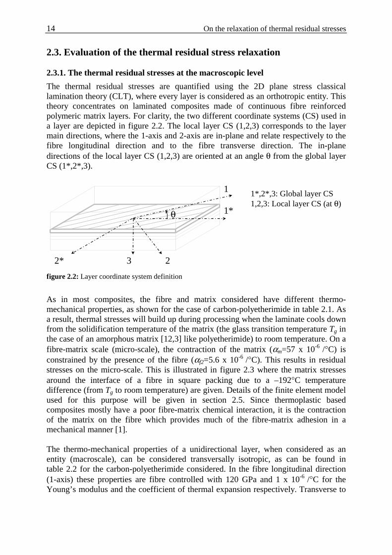
The thermal residual stresses are quantified using the 2D plane stress classical lamination theory (CLT), where every layer is considered as an orthotropic entity. This theory concentrates on laminated composites made of continuous fibre reinforced polymeric matrix layers. For clarity, the two different coordinate systems (CS) used in a layer are depicted in figure 2.2. The local layer CS (1,2,3) corresponds to the layer main directions, where the 1-axis and 2-axis are in-plane and relate respectively to the fibre longitudinal direction and to the fibre transverse direction. The in-plane directions of the local layer CS (1,2,3) are oriented at an angle θ from the global layer CS (1*,2*,3).
θ 1*
1
2* 23
1*,2*,3: Global layer CS1,2,3: Local layer CS (at θ)
figure 2.2: Layer coordinate system definition
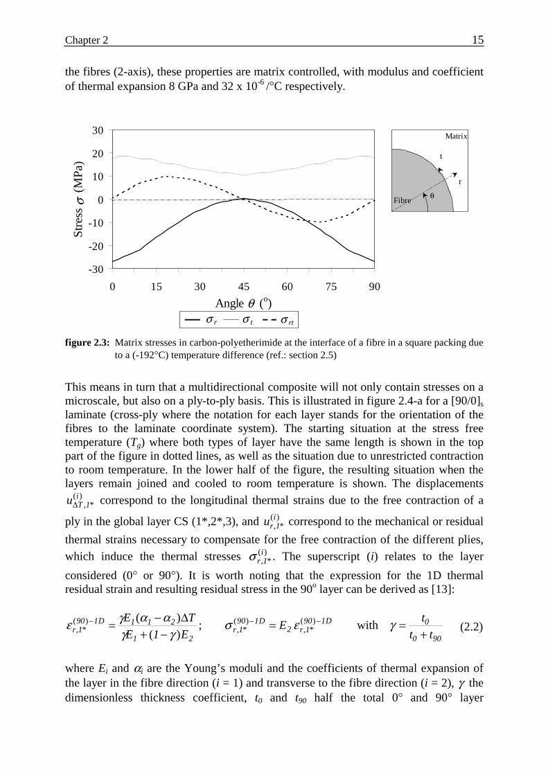
As in most composites, the fibre and matrix considered have different thermo-mechanical properties, as shown for the case of carbon-polyetherimide in table 2.1. As a result, thermal stresses will build up during processing when the laminate cools down from the solidification temperature of the matrix (the glass transition temperature Tg in the case of an amorphous matrix [12,3] like polyetherimide) to room temperature. On a fibre-matrix scale (micro-scale), the contraction of the matrix (αm=57 x 10-6 /°C) is constrained by the presence of the fibre (αf2=5.6 x 10⁻⁶ /°C). This results in residual stresses on the micro-scale. This is illustrated in figure 2.3 where the matrix stresses around the interface of a fibre in square packing due to a –192°C temperature difference (from Tg to room temperature) are given. Details of the finite element model used for this purpose will be given in section 2.5. Since thermoplastic based composites mostly have a poor fibre-matrix chemical interaction, it is the contraction of the matrix on the fibre which provides much of the fibre-matrix adhesion in a mechanical manner [1]. The thermo-mechanical properties of a unidirectional layer, when considered as an entity (macroscale), can be considered transversally isotropic, as can be found in table 2.2 for the carbon-polyetherimide considered. In the fibre longitudinal direction (1-axis) these properties are fibre controlled with 120 GPa and 1 x 10⁻⁶ /°C for the Young’s modulus and the coefficient of thermal expansion respectively. Transverse to
Chapter 2 15
the fibres (2-axis), these properties are matrix controlled, with modulus and coefficient of thermal expansion 8 GPa and 32 x 10-6 /°C respectively.
-30
-20
-10
0
10
20
30
0 15 30 45 60 75 90
Angle θ (o)
Stre
ss σ
(M
Pa)
σ r
Fibre
r
t
θ
Matrix
σ t σ rt figure 2.3: Matrix stresses in carbon-polyetherimide at the interface of a fibre in a square packing due
to a (-192°C) temperature difference (ref.: section 2.5)
This means in turn that a multidirectional composite will not only contain stresses on a microscale, but also on a ply-to-ply basis. This is illustrated in figure 2.4-a for a [90/0]s laminate (cross-ply where the notation for each layer stands for the orientation of the fibres to the laminate coordinate system). The starting situation at the stress free temperature (Tg) where both types of layer have the same length is shown in the top part of the figure in dotted lines, as well as the situation due to unrestricted contraction to room temperature. In the lower half of the figure, the resulting situation when the layers remain joined and cooled to room temperature is shown. The displacements
)(*,
i1Tu∆ correspond to the longitudinal thermal strains due to the free contraction of a
ply in the global layer CS (1*,2*,3), and )(*,
i1ru correspond to the mechanical or residual
thermal strains necessary to compensate for the free contraction of the different plies,
which induce the thermal stresses )(*,
i1rσ . The superscript (i) relates to the layer
considered (0° or 90°). It is worth noting that the expression for the 1D thermal residual strain and resulting residual stress in the 90o layer can be derived as [13]:
900
0D1901r2
D1901r
21
211D1901r tt
tE
E1E
TE
+==
−+∆−= −−− γεσ
γγααγε with;
)(
)( )(*,
)(*,
)(*, (2.2)
where Ei and αi are the Young’s moduli and the coefficients of thermal expansion of the layer in the fibre direction (i = 1) and transverse to the fibre direction (i = 2), γ the dimensionless thickness coefficient, t0 and t90 half the total 0° and 90° layer

16 On the relaxation of thermal residual stresses
thicknesses respectively and ∆T the temperature difference between Tg and room temperature (∆T =TR-Tg). Nairn [12] confirmed this simple approach by experiment using photoelasticity and non-symmetric laminate curvature measurements on carbon-polysulfone.
: at Tg
: ∆T
: at RT
90o
0o
90o
90o
0o
90o
x
x
z
z
t90/2
t0
z
+--
+
)(*,
901ru
)(*,
901Tu∆
)(*,
01ru
)(*,
i1rσ
)(*,
01Tu∆
iα
(a) (b) figure 2.4: 1D representation of the macroscopic residual strains in a cross-ply laminate:
(a): Initial situation at Tg (dotted lines) and situation due to unrestricted contraction at room temperature (hard line); Situation at room temperature (thick lines) (b): Resulting stress profile
As far as the 2D (plane stress) solution according to the Classical Laminate Theory (CLT) [14] is concerned, a similar reasoning for the strain build-up as for the 1D model (figure 2.4) remains which takes into account the Poisson’s effects. The expressions for the residual strains in the 90° layer of a cross-ply [0/90]s laminate are respectively:
TAAA
NANAT
AAA
NANA12
122211
T212
T111CLT90
2r22122211
T212
T122CLT90
1r ∆−−
−=∆−−
−= −− αεαε )(*,
)(*, ; (2.3)
( )
( )
21290
210
2190
120
1220
2290
11190
220
11
0j
0ij
90j
90ij
Ti
0ij
90ijij
EQQQQEQQEQQ
21jiQ1QhTN
21jiQ1QhA
ψνψψ
γαγα
γγ
========
=+−∆=
=+−=
)()()()()()()()(
)()()()(
)()(
;;
,,;)(
,,;)(:with

Chapter 2 17
900
0
1
21221
2112 tt
t
E
E
1
1
+==
−= γνν
ννψ ;;:and
where h is the total laminate thickness. The factor ψ is around 1.01 for unidirectional layers and is taken equal to 1 for simplicity. The thermal residual stress in the 90o layer in the main direction of a [0/90]s laminate can be derived as:
CLT902r
9012
CLT901r
9011
CLT901r QQ −−− += )(
*,)(
*,)(
*, εεσ (2.4)
The results obtained with this model were confirmed by Eijpe’s detailed measurements of residual stress profiles on carbon-polyetherimide shortly after manufacture using a modified layer removal approach [3,15]. As an indication, table 2.3 gives a comparison between the 1D and 2D approaches for a carbon-polyetherimide cross-ply [90/0]s laminate having the layer properties as shown in table 2.2. Taking the second in-plane dimension into account gives a 5 % difference in stress, although the difference in strain is negligible.
Solution: )(*,
901rε )(
*,901rσ
1D (2.2) 0.56 43.8 2D (2.4) 0.55 41.9
table 2.3: Comparison between the 1D and 2D solutions for both the residual strain and stress in the 90° layer, shortly after manufacture.
2.3.2. Micromechanics models
The stiffness properties of a layer in the fibre direction are controlled by the fibre properties, as shown by the rule of mixture in parallel form (also called Voigt’s model) used for the elasticity modulus E1:
)( fmf1f1 V1EVEE −+= (2.5)
where Vf is the fibre volume fraction. As an indication, a 10 % decrease in matrix modulus only produces a 0.1 % decrease in the layer longitudinal modulus because Ef1>>Em . It means that the viscoelasticity of the matrix will have no direct effect on the behaviour of the 0o layer. Transverse to the fibre direction, the properties are mainly controlled by the properties of the matrix. This is where the residual stress relaxation will find its origin. Amongst different relations available (Reuss, Halpin-Tsai) for predicting the transverse elasticity modulus E2, a series-parallel model was used here leading to the following expression [8,16]:

18 On the relaxation of thermal residual stresses
2fffmf
2fmfmf2 EV1VEV
EEVEV1E
)()(
−++−= (2.6)
As an indication, a 10 % decrease in the matrix elasticity modulus gives a 7.2 % decrease in the layer transverse modulus. It is worth mentioning that using the linear elastic properties as defined in table 2.1 in equation (2.6) gives an E2 of 7.7 GPa, which compares well with the 7.85 GPa determined experimentally for the unidirectional material. It should be noted that the theoretical value of E2 depends on the transverse fibre modulus Ef2, whose value is difficult to determine experimentally. The value used here (Ef2=14 GPa) was taken from the literature [8,17] and was originally determined by comparison between elasticity modulus measurement on 90° unidirectional laminate and micro-mechanical models.
2.3.3. Evaluation of the stress relaxation
The procedure for evaluating the stress relaxation due to the matrix viscoelasticity is based on the calculation of the thermal residual stress with equations (2.3) and (2.4), using the series-parallel model for the transverse modulus E2 (2.6). In the series-parallel model, the matrix linear elastic modulus mE is replaced by the relaxation
modulus )(σrelaxmE as shown in figure 2.1. The procedure is time iterative, and starts
with the 43.8 MPa residual stress as calculated with the linear elastic properties of table 2.1. This assumes, therefore, that the matrix stress is taken as the layer transverse stress )(
*90
1σ . This stress value is input in the second order fit after 1 hour as shown in figure 2.1 to obtain the matrix creep modulus after 1 hour (and therefore the relaxation modulus). The resulting relaxation modulus of the layer is then calculated with the micromechanics relation (2.6), which is then used for calculating the residual stress after 1 hour. This loop, as summarised in figure 2.5, is iterated for the available time steps (1, 10, 100, 1000, 10000 hours). It is important to note at this stage that the relaxation does not actually start at room temperature, but during fabrication from the moment the matrix state changes from rubbery to plastic condition at Tg. Still, the initial value at room temperature is used as it corresponds to measurements performed on the same material by Eijpe [3]. The resulting calculated residual stress in the 90° layer as a function of time (logarithmic scale) is shown in figure 2.6. A detail of the 100 first hours is also shown on this graph in order to emphasise the rapid relaxation in this first period of time. As an indication, the model just described predicts a 13 % decrease in residual stress after 240 hours.

Chapter 2 19
a )()(*, i
2901relax tσ + b )()(
*, i90
1relax tσ + c fit in figure 2.1
Series-parallel model (2.6)
Thermo-elasticity calculation (2.3), (2.4)
)()(*, 0
901relax tσ (2.4)
i=1
)( irelaxm tE
i+1 )( i
relax2 tE
)()(*, i
901relax tσ
figure 2.5: Procedure for the evaluation of the thermal stress relaxation.
30
35
40
45
50
1 10 100 1000 10000
time (h)
(90)
σre
lax,
1* (
MPa
)
35
40
45
0 50 100
time (h)
Str
ess
(MP
a)
figure 2.6: Modelled relaxation of the residual stress in a carbon-PEI cross-ply laminate

20 On the relaxation of thermal residual stresses
2.4. Experimental evaluation of the relaxation
2.4.1. Measurement of the relaxation
The experimental quantification of the thermal residual stress relaxation was performed by using a particularity of unsymmetric laminates. Although pressed in a flat mould, a [90/0] laminate will show a synclastic (cylindrical) or an anticlastic (saddle) shape depending on the thickness to the plate length ratio [18]. One of such a cylindrical shape is shown in the top section of figure 2.7-a. When the laminate is pressed back to a flat shape (by using the laminating press at room temperature), a strain profile as shown in figure 2.7-b is obtained. The resulting stress levels reached in the flattened laminate (see same figure) are similar to those obtained in a symmetric [0/90]s laminate as was shown in figure 2.4-b. It may therefore be assumed that the thermal stress relaxation in the flattened unsymmetric laminate will occur in much the same way as it occurs in its symmetric counterpart.
0o
0.190.44
-0.150.1 )(
*,i1rε (%)
43
-43 )(*,
i1rσ
0.54
-0.05 )(*,
i1rε (%)
(MPa)
1831
-170119 )(
*,i1rσ (MPa) +-
p[90/0]: Flattened [90/0]:
90o
90o
0o
90o
0o
0o
90o
+-+-
+-
(a) (b) figure 2.7: Strain and stress profile of a non-symmetric [0/90] laminate: (a): in its original free-
curved form; (b): when flattened.
The relaxed modulus of the 90° layer can be determined at any time, by releasing the flattened plate and measuring the remaining plate curvature κ. The relaxed modulus can then be calculated from the curvature κ using the following equation (2.7), by assuming the linear elasticity of the 0° layer. This equation can be obtained by using the basic assumptions of the classical lamination theory as shown in appendix A.

Chapter 2 21
)(
)())()(()()()(
th2
th4th14T24th14T24EtE
2221212
1relax2 κ
κκαακαα −+−∆++−∆−=
(2.7) In this relation, h is the total laminate thickness and κ(t) the curvature of the laminate
at any time t. Following the determination of )(tE relax2 , the 2D CLT model
(equation (2.4)) can be used to determine the residual stresses in the transverse direction. Summarising, the evaluation of the relaxation of the thermal residual stress requires the flattening of an unsymmetric laminate in order to obtain a strain profile equivalent to that of the symmetric laminate. The experimental evaluation of the residual stress relaxation is then performed through the measurement of the curvature of the released plate, which is related to the relaxation modulus of the 90° layer and hence to the level of internal stresses. It should be noted that releasing the laminate from its flat state induces a strain reduction from 0.54 % to an average of 0.31 % as can be seen in figure 2.7. This could be taken into account using the Boltzmann superposition principle [11]. The relatively short plate release time necessary for each curvature measurement (around 10 minutes) led to the assumption that this effect can be neglected. The strain profiles shown in figure 2.7 also make clear that the creep modulus evaluation through the curvature measurement does not imply any extra loading. Three 250 mm x 250 mm [904/04] laminates where tested. Their average thicknesses were 1.34, 1.35 and 1.31 mm. The in-plane dimensions of the plates were selected so as to obtain a cylindrical shape (in contrast to an anticlastic shape) at room temperature, in order to facilitate the curvature measurement. The choice of plate length is fairly critical, since calculations for a square [904/04] laminate using the carbon-polyetherimide material properties of table 2.1 (following a method proposed by Hyer [18]) indicate a transition from synclastic to anticlastic curvature at a plate length of 150 mm. The measurement of the curvature was performed on an X-Y table coupled to an optical non-contacting displacement measuring system. This was performed every hour for the initial 5 to 10 hours and then irregularly until a maximum of 700 hours. During these measurements, it was observed that transverse cracking occurred (matrix cracking parallel to the fibres, mostly forming on a plane perpendicular to the loading direction). This cracking mechanism was observed to be time dependent and gave a non-homogeneous crack distribution. Some cracks covered the whole length of the plate at the end of the test, others did not grow further than 1 or 2 cm. The crack growth and density were not evaluated at this stage.

22 On the relaxation of thermal residual stresses
2.4.2. Results
Analysing the experimental results gives the relaxed transverse residual stress-time diagram shown in figure 2.8. The theoretically predicted residual stress relaxation characteristic for the carbon/PEI system (shown earlier in figure 2.6) is reproduced for the first 1000 hours in this figure.
30
35
40
45
50
1 10 100 1000time (h)
Plate 1 Plate 2 Plate 3 Model
Power law fit
brelax ta=)90(
*1,σ
a (MPa) bPlate 1 47.4 -0.042Plate 2 45.8 -0.052Plate 3 46.8 -0.053Model 41.8 -0.019
σre
lax,
1* (
MPa
)(9
0)
figure 2.8: Thermal residual stress derived from relaxation measurements.
The thermal residual stress derived from the curvature of each of the tested laminates can be approximated by a power law as shown in figure 2.8. Compared to the results of the model, two observations can be made. First the residual stress at 1hour is on average 12 % higher than the modelled stress. This corresponds to a 6 % increase in curvature. Similar differences were obtained and commented on during measurements on glass-polyetherimide [19], but is not the most significant factor to report on. More significantly, the power coefficient of the power law fit shows that the measured plates relax more rapidly than the model predicts. An average of -0.05 for the power coefficient, b, of the three plates is 60 % lower than for the model. As an indication, the average measured decrease in thermal residual stress reaches 24 % after 240 hours. Although there is considerable variation between the measured laminates (-21.4 %, -25.8 %, -26.2 % for the plate 1, 2 and 3 respectively), this decrease is in absolute value clearly higher than the one predicted by the model (-13 %). Relating this difference to the observed time dependent transverse cracking formation is straightforward. It has been recognised in the past three decades that the presence of transverse cracking affects the continuity of the 90° layer and therefore its thermo-mechanical properties [20,6,7]. This means that the transverse modulus decrease calculated from the curvature of the non-symmetric laminate is not only due to the viscoelastic nature of the matrix and thus the 90° layer, but also to the decrease in transverse elasticity modulus due to the presence of cracks. It is tempting to refer to a

Chapter 2 23
‘transverse cracking induced relaxation’ but care is needed when using this appellation. Where the viscoelasticity induced stress relaxation is recoverable, the decrease of the transverse elasticity modulus due to the transverse cracks is not. This can be checked experimentally by heating the plates after relaxation in their original mould at low pressure just above Tg. This allows the viscoelastic relaxation to be recovered, but is assumed not to permit enough matrix flow for the cracks to close. The results of the curvature measured on the three plates after fabrication, after 700 hours relaxation and after recovery are compared in table 2.4.
Curvature κ (1/m)
½ hour after fabrication
after 700 hours relaxation
½ hour after recovery
Plate 1 4.14 - 3.86 Plate 2 4.00 3.31 3.66 Plate 3 4.11 3.36 3.99
table 2.4: [0/90] curvature after fabrication, 700 hours relaxation and after recovery.
The results show that only part of the measured stress relaxation is recovered. Assuming the viscoelastic recovery has fully taken place, the difference in curvature and therefore the irreversible decrease in transverse elasticity modulus can be assigned to the transverse cracks. From these results, it is possible to evaluate the decrease in transverse elasticity modulus E2 resulting from the time dependent growth of transverse cracks after 700 hours, by input of the curvatures after fabrication and after recovery into relation (2.7). For this purpose, the longitudinal modulus E1 is assumed not to be affected by the transverse cracking. Although a transverse crack deteriorates the integrity of a layer loaded transversally, the fact that the crack runs along the fibres makes its influence less critical when the layer is loaded along the fibres. The estimated decrease in transverse elasticity modulus due to the crack formation for the three plates is respectively –14 %, -15 % and –6 %. Although the variation on this result is large and the sample contains only 3 specimens, it shows that the decrease of the transverse modulus due to the presence of transverse cracking is not negligible. It is difficult to quantify this mechanism precisely, since it was observed during the relaxation experiments that the process is time dependent.
2.5. On the formation of the transverse cracks The results just presented suggest that transverse cracks in cross-ply carbon-polyetherimide laminated plates form under only the presence of thermal residual stresses. The origin of these cracks in this particular case is studied in this section. Transverse cracks, also called matrix cracking, run parallel to the fibres through the thickness layer. Abedian and Szyszkowski [21] suggested on the basis of a 3D fibre-matrix model that, at the free ends of the fibres (therefore at the edges of a laminate), tensile radial stresses at the fibre/matrix interface may be a major factor for crack initiation in carbon-epoxy laminates. In the inner zone of a laminate, (i.e. far enough

24 On the relaxation of thermal residual stresses
from the edges) the same authors suggested that tensile hoop stresses at the fibre-matrix interface might cause cracking when cooled. These results confirmed experimental observation made by Morris et al. [22], who found fibre-matrix interface cracking at the edges of carbon-epoxy unidirectional laminates when cooling from the processing temperature. Although the interface in epoxy based composites is fairly well defined and controlled, the adhesion of the fibre in a thermoplastic matrix is the result of physical interaction, due to the shrinkage of the matrix onto the fibres, rather than the result of a chemical interaction [23]. A transverse crack then follows a path along these weak interfaces. A typical micrograph (figure 2.9) of the 90° layer of a [9012] carbon-polyetherimide laminated beam after bending testing shows such a transverse crack. The crack can be seen passing through the matrix-fibre interface from fibre to adjacent fibre. The crack is not observed passing through the matrix (or through a fibre), except to jump across a resin-rich region separating fibres and the path of the crack. The fact that transverse cracking in the carbon-polyetherimide system is more an interface cracking issue than a matrix cracking mechanism is confirmed with a Scanning Electron Microscopy (SEM) study of the fracture surface. A typical SEM image of a transverse crack failure surface of a carbon-polyetherimide [904/04] cross-ply laminated beam (figure 2.10) shows some clean fibres (without matrix residues adhering) suggesting a poor fibre-matrix adhesion, with only scarce matrix surfaces with traces of plastic deformation.
figure 2.9: Transverse crack in a carbon-polyetherimide unidirectional
laminate after a bending test
Although some crack growth initiated at the plate edges, the majority of the transverse crack growth during the relaxation measurements initiated well within the plate boundaries, well away form the edges. For the case of the non-edge crack initiation, a micro-mechanical model aimed at evaluating the stress situation at the fibre-matrix

Chapter 2 25
interface can be considered as a 2D plane-strain model, in a plane perpendicular to the fibre main axis [21].
figure 2.10: SEM of a carbon-polyetherimide transverse crack surface.
2.5.1. Model description
A FEM program ANSYS was used to get an overview of the stresses around a fibre in a strain field representing the thermal residual stresses in a 90° layer of a [904/04]s laminate. The fibre distribution within a layer was assumed to correspond to a square pattern, which reduced the geometry modelled to a quarter of a fibre with adjacent matrix as shown in figure 2.11. The model used was a 2D plane strain in a plane perpendicular to the main axis of the fibre. The square sides have unit dimension, and the fibre radius is calculated in order to reflect the fibre volume fraction as shown by equation (2.8).
πfv4
r = (2.8)
The mesh used 4-noded plane elements. A typical distribution of the elements is shown in figure 2.11. It is recognised that, for a more detailed prediction, the fibre-matrix interface needs to be taken into account in fibre-matrix models [24,25,26]. No quantitative data on the carbon-polyetherimide adhesion could be found in the literature. The observations made on the SEM picture in figure 2.10 led to two extreme sets of fibre-matrix interface boundary conditions:
BC1. The nodes at the fibre-matrix interface are directly connected, assuming a perfect fibre-matrix interface.

26 On the relaxation of thermal residual stresses
BC2. The nodes at the fibre-matrix interface are connected through contact elements (high stiffness under compression, no stiffness under tension), assuming no chemical bonding between the fibre and the matrix adhesion. However, an arbitrary friction coefficient of 0.8 was assumed.
x
10
1
z
r
r figure 2.11: Finite element geometry of
square fibre packing repeating unit.
The material properties used are the linear elastic values defined in table 2.1. Stress relaxation is not considered here and the model described represents the situation immediately after fabrication. The thermally induced loads on the model were applied in two steps. The first step (LS1) is a thermal strain over the whole model in order to model the free contraction of the 90° layer, due to the difference in temperature during fabrication, as shown in the upper part of top of figure 2.4-a. The second step (LS2) models the constraining effect of the 0° layer in a cross-ply laminate as shown in the lower part of figure 2.4-a. In detail:
LS1. A temperature difference ∆T (-192°C), which models the free contraction of a unidirectional [90] laminate after fabrication is applied.
LS2. The same temperature difference, with a )(*,
901ru displacement in the x-
direction at x=1, as calculated with the classical laminate theory, which models the situation of the [904/04]s laminate after fabrication.
2.5.2. Results
The stress situation after the first load step, LS1, (situation in the unidirectional [90] laminate) is equal for both sets of boundary conditions describing the fibre-matrix interface. This is due to the compressive radial stress acting on the fibre as shown in figure 2.3 in section 2.3.1 of this paper. The resulting tensile tangential (or hoop) stress

Chapter 2 27
is fairly constant around the interface at 15MPa. The von Mises stress profile with the perfect fibre-matrix adhesion is shown in figure 2.12 and makes it possible to analyse the stress situation in the matrix. A maximum of 64 MPa can be found in the matrix at an angle θ of 0° and 90°. Considering that the yield stress of the matrix at room temperature is around 110MPa [10], no damage is expected to be induced by the temperature difference on any unidirectional laminate transverse to the fibre direction.
figure 2.12: von Mises stress contour plot with perfect adhesion
(BC1) and temperature gradient (LS1).
When applying a positive displacement in the x-direction upon the last load step to simulate the strain field induced in a cross-ply laminate (Load step LS2), two extreme situations are created when using the two sets of boundary conditions. The model can be evaluated by calculating the model transverse elasticity modulus
femE2 , by dividing the modelled average axial stress at x = 1 (see figure 2.11) by the
strain imposed on the model. The results for both types of interface are:
Perfect interface (BC1): femE2 =7 GPa
No adhesion (BC2): femE2 =2 GPa
Assuming perfect adhesion at the interface (Boundary condition BC1), a value of fem2E
of 7 GPa is found, which is lower than the value determined experimentally (7.85 GPa). This can be explained by the sensitivity of the modelled values to the transverse

28 On the relaxation of thermal residual stresses
fibre modulus used, which is always quoted in the literature as an approximation. Upgrading, for example, the transverse fibre modulus from 14 GPa [8] to 20 GPa [26] is enough to obtain an 8 GPa composite transversal modulus with the perfect interface. The model is therefore considered acceptable as a first approach. It is worth noting that the coefficient of friction has no influence on the result. At the other extreme, the model having no interface (BC2) provides a transverse modulus of 2 GPa. The cylindrical stresses in the matrix at the fibre-matrix interface in the 90° layer of a cross-ply laminate with the assumed perfect interface (BC1) and following LS2 are shown in figure 2.13.
-50-40-30-20-10
01020304050
0 15 30 45 60 75 90
Angle θ (o)
Stre
ss σ
(M
Pa)
σ r σ t σ rt
Fibre
r
t
θ
Matrix
figure 2.13: Matrix stresses at the fibre-matrix interface of a 90° layer in a carbon-polyetherimide
cross-ply laminate, assuming a perfect interface.
The von Mises stress contours are shown in figure 2.14 for BC1 and figure 2.15 for BC2. In both cases, the maximum von Mises stress is reached in the matrix at an angle of 90° from the x-axis. In the case of the perfect interface (figure 2.14) the maximum von Mises stress of 88MPa is still lower than the matrix yield stress (110 MPa). In the case when no interface adhesion is assumed (figure 2.15), the von Mises stress is maximum at the interface (124 MPa) and is clearly higher than the matrix yield stress. This suggests the formation of plastic zones in the matrix near weak interfaces at an angle of 90° from the x-axis. A study by Woods and de Lorenzi [27] showed that crazing in pure polyetherimide always started on an elastic-plastic interface. It seems fair to assume that the inherent presence of defects in a composite, combined with the formation of local plastic zones could lead to the formation of crazes.

Chapter 2 29
figure 2.14: von Mises stress contour plot with perfect adhesion (BC1) and
the cross-ply induced stress field (LS2).
figure 2.15: von Mises stress contour plot with no adhesion (BC2) and the
cross-ply induced stress field (LS2).

30 On the relaxation of thermal residual stresses
The load necessary to let the crazes grow and finally form a crack by the fracture of the fibrils is most probably induced by the relaxation test procedure. As pointed out earlier in this paper, releasing the plate in order to measure the plate curvature does not add any extra loading. However, the flattening-releasing procedure induces what can be compared to a low-frequency cyclic loading, switching between the two stress situations sketched in figure 2.7-a and b. This sort of fatigue loading could be responsible for the craze growth, which eventually grows into a transverse crack, as noticed during the relaxation experiments. Following this argument, zones of better fibre-matrix adhesion can act as a crack arrest zone, since the von Mises stress is lower than the yield stress in this case. Moreover, it is possible that this mechanism will predominate in zones of high fibre concentration. The model presented is based on a measured averaged fibre-volume fraction Vf of 50 %. It is clear that the fibre concentration will vary within the laminate (see for example figure 2.9). The model was therefore reconsidered with different values of fibre volume fraction. The maximum level of von Mises stress is not strongly dependent on the fibre volume fraction as shown in table 2.5. It varies from 114 MPa to 126 MPa for the fibre volume fraction varying from 0.32 to 0.68.
Fibre volume fraction Vf 0.32 0.51 0.68
Max von Mises stress (MPa) 114 124 126
table 2.5: Maximum von Mises stress in the matrix as a function of the fibre volume fraction.
If a plastic zone is defined as the zone where the von Mises stress exceeds 110 MPa, figure 2.16 shows, in grey, the plastic zone for the fibre volume fraction varying from 0.32 to 0.68. The model predicts the largest plastic zone for the model having the highest fibre volume fraction (figure 2.16-a). In this case, the plastic zone even connects the volume between two adjacent fibres. The formation of crazes should therefore be predominant in such regions of close fibre concentration.
(a) (b) (c) figure 2.16: Zone where the von Mises stress is greater than the yield stress of polyetherimide
(110MPa) for different fibre volume fractions: (a): Vf=0.68; (b): Vf=0.51, (c): Vf=0.32

Chapter 2 31
2.6. Conclusion This paper has considered the quantification of the thermal residual stress relaxation in [0/90]s cross-ply laminates. Numerical and experimental validation was performed on carbon-polyetherimide laminated plates. It has become obvious that the measurement of the relaxation modulus was not restricted to the quantification of viscoelastic effects. Secondary effects occurred in the form of time dependent transverse cracking (also called matrix cracking), which is known to significantly deteriorate the structural integrity of composites. For the system considered, the contribution of both viscoelastic and damage mechanisms on the relaxation were of the same order of magnitude, leading to a 24 % decrease in residual stress after 240 hour. The damage mechanism cannot strictly be named relaxation, as the process of crack formation is not reversible as is the viscoelasticity-related relaxation. This implies that the relaxation affects the residual stress but not the actual thermo-mechanical properties of the layer. The matrix damage, however, does affect the macroscopic elasticity modulus of the layer in the direction transverse to the fibres and therefore influences the stress situation in a structure. The transverse cracking observed was also supported by a 2D fibre-matrix model. This finite element model considered the stress situation in the matrix near the fibre-matrix interface with the thermal internal stresses as the only loading. It is shown that crazing can occur near poor fibre-matrix interfaces, especially in zones of high fibre concentration.
32 On the relaxation of thermal residual stresses
References 1. Pegoraro, M., Di Landro, L.; “Influence of components and interface conditions on mechanical
properties of composites and blends”; Makromolekulare Chemie, Macromolecular Symposia, Vol. 70/71 (1993), p. 193-212.
2. Nairn, J.A., Zoller, P.; “The development of residual thermal stresses in amorphous and semicrystalline thermoplastic matrix composites.”; Toughened Composites, ASTM STP 937, Johnston, N.J., Ed. (1987), p. 328-341.
3. Eijpe, M.P.I.M.; “A modified layer removal method for determination of residual stresses in Polymeric composites”; PhD Thesis, University of Twente (NL), ISBN 9036510155 (1997).
4. Kim, P., Toll, S., Måson, J-A.E.; “Micromechanical analysis of the viscoelastic behavior of composites”; IUTAM Symposium on Microstructure-Property Interactions in Composite Materials, Ed. E. Pyrz (1995), p. 165-176.
5. Halpin, J.C., Kardos, J.L,; “The Halpin-Tsai equations: a review”; Polymer Engineering & Science, Vol. 16 (1976), p. 344-352.
6. Talreja, R.; “Transverse cracking and stiffness reduction in composite laminates”; J. of Composite Materials, Vol. 19 (1985), p. 355-375.
7. Dvorak, G.J., Laws, N., Hejazi, M.; “Analysis of progressive matrix cracking in composite laminates- I: Thermoplastic properties of a ply with cracks”; J. of Composite Materials, Vol. 19 (1985), p. 216-234.
8. Gibson, R.F.; “Principles of composite materials mechanics”, McGraw-Hill (1994). 9. Caruso, J.J., Chamis, C.C.; “Assessment of simplified composite micromechanics using three-
dimensional finite element analysis”, J. of Composites Technology & Research, Vol. 8 (1986), p. 77-86.
10. ULTEM 1000 data sheets, CAMPUS 4.0, GE Plastics Europe (1996). 11. Williams, J.G.; “Stress analysis of polymers”; Ellis Horwood Limited (1980). 12. Nairn, J.A., Zoller, P.; “Matrix solidification and the resulting residual thermal stresses in
composites”; J. of Materials Science, Vol. 20 (1985), p. 355-367. 13. Collings, T.A., Stone, D.E.W.; “Hygrothermal effects in CFRP laminates: strains induced by
temperature and moisture”; Composites, Vol. 16 (1985), p. 307-316. 14. Powell, P.C.; “Engineering with fibre-polymer laminates”; 1994, Chapman & Hall, London,
ISBN 0-412-49620-8 15. Eijpe, M.P.I.M., Powell P.C., “A modified layer removal analysis for the determination of
internal stresses in polymer composites”; J. of Thermoplastic Composite Materials, Vol. 10, (1996), p. 145-151.
16. Hopkins, D.A., Chamis, C.C.; “A unique set of micromechanics equations for high temperature metal matrix composites”; in Testing Technology of Metal Matrix Composites, Giovanni, P.R. and Adsit, N.R. eds., ASTM STP 964 (1988), p. 159-176.
17. Rogers, K.F., Phillips, L.N., Kingston-Lee, D.M., Yates, B., Overy, M.J., Sargent, J.P., McCalla, B.A.; “The thermal expansion of carbon fibre-reinforced plastics”; J. of Materials Science, Vol. 12 (1977), p. 718-734.
18. Hyer, M.W.; “Calculations of the room-temperature shapes of unsymmetric laminates”; J. of Composite Materials, Vol. 15 (1981), p. 296-310.
19. Peeters, L.J.B, Powell, P.C., Warnet, L.L.; “Thermally-induced shapes of unsymmetric laminates”; J. of Composite Materials, Vol. 30 (1996), p.603-626.
20. Hahn, H.T., Tsai, S.W.; “On the behavior of composite laminates after initial failures”; J. of Composite Materials, Vol. 8 (1974), p. 288-305.
21. Abedian, A., Szyszkowski, W.; “Influence of the free surface on the thermal stresses in unidirectional composites”; Composites Part A, Vol. 28A (1997), p. 573-579.
22. Morris, W.L., Inman, R.V., Cox, B.N.; “Microspcopic deformation in a heated unidirectional graphite-epoxy composite”; J. of Materials Science, Vol.24 (1989), p. 199-204.
23. Pegoraro, M., Di Landro, L.; “Influence of components and interface conditions on mechanical properties of composites and blends”; Makromolekulare Chemie, Macromolecular Symposia, Vol. 70/71 (1993), p. 193-212.
Chapter 2 33
24. Ishikawa, T.; “Strengths and thermal residual stresses of unidirectional composites”; J. of
Composite Materials, Vol. 16 (1982), p.40-52. 25. Wacker, G., Bledski, A.K., Chate, A.; “Effect of interphase on the transverse Young’s modulus
of glass/epoxy composites”; Composites Part A, Vol. 29A (1998), p. 619-626. 26. de Kok, J.; “Deformation, yield and fracture of unidirectional composites in transverse
loading”; PhD. Thesis, University of Eindhoven (NL), (1995). 27. Woods, J.T., Delorrenzi, H.G.; “An assessment of crazing criteria for polyetherimide in three-
dimensional stress space”; Polymer Engineering and Science, Vol. 33 (1993), p. 1431-1437.

34 Variation of the laminate lay-up

Chapter 3 35
Chapter 3
The effect of residual stress on transverse cracking in cross-ply carbon-polyetherimide laminates under bending: Variation of the laminate lay-up
3.1. Introduction Thermal residual stresses are inherent to fibre reinforced composites due to the heterogeneity of the thermo-mechanical properties of their two constituents. Such stresses build up when composite structures are cooled down from the processing temperature to the test temperature. Residual stresses will be present on both a fibre-matrix scale (micro-scale), and on a ply-to-ply scale (macro-scale) in laminates built up from layers with different orientations. It is recognised that these stresses should be taken into account in any stress analysis. Some authors have reported on the occurrence of matrix related damage in composite laminates due to the presence of thermal residual stresses. Morris, Inman and Cox [1] observed fibre-matrix interface cracking in carbon-epoxy composites due to the cooling from the processing temperature. Nairn and Zoller [2] noticed some matrix cracking occurring in the last stage of the cooling down of carbon-PET non-symmetric laminates, when studying the development of thermal residual stresses. Similarly, Warnet, Reed, and Akkerman [3 (chapter 2 of this thesis)] observed the formation of matrix cracking during the experimental evaluation of the relaxation of thermal residual stresses in non-symmetric carbon-polyetherimide laminates. It is helpful to distinguish between micro-damage and matrix cracking. Micro-damage occurs locally on a fibre-matrix scale (for example the interface cracking observed in [1]) and can form the initiation of a matrix crack. A matrix crack (also called transverse crack) runs parallel to the fibre in the thickness direction of a layer. It is known that matrix cracking will affect the properties of composites [4,5,6] and acts as a trigger for further damage mechanisms [7,8], because it forms an open path for environmental deterioration and delamination development. This paper studies the effects of residual stresses on the matrix cracking of cross-ply [90/0]s laminated beams under 3 point bend loading. Experiments were performed on carbon-polyetherimide laminates having different levels of thermal stresses. Different levels of thermal stresses were obtained by producing the laminates of different lay-ups and by alternatively using carbon-polyetherimide or glass-polyetherimide plies for the central 0° layer. A carbon-polyetherimide system was chosen for its capacity of producing high levels of thermal stresses, mainly arising from the large difference between the temperature at which the stresses build up (215°C) and the test temperature (23°C). The number of outer carbon-polyetherimide 90° layers in the

36 Variation of the laminate lay-up
beams was kept constant for all the lay-ups used, in order to prevent geometrical factors affecting the results. It was shown by Parvisy, Garrett and Bailey [9] that the stress at which transverse cracking occurs in tensile testing is inversely proportional to the thickness of the 90° layer. This effect is referred to as the constraining effect of the 0° layer. The results of the experiments were first analysed from a macroscopic point of view, where the layers are considered transversally isotropic. For this purpose, both the bending compliance before the occurrence of the first transverse crack and the macroscopic stress at the initiation of the transverse crack are considered. Also the experimental energy released at the formation of the first transverse crack is calculated. The measured bending compliances of the cross-ply beams are compared to values predicted by analytical approximations. Anticipating the conclusions drawn from this analysis, the comparison between the analytical and the experimental compliance indicates the existence of a thermal stress level above which micro-damage is induced. This proposition is supported by the analysis of a finite element micro-mechanics fibre-matrix model, loaded only with the residual stresses. The evaluation of the stress at failure as well as the energy released are used to evaluate the validity of, respectively, a maximum stress criterion and an energy approach as a failure criterion. First an overview is given of the properties of the carbon-polyetherimide composite used. The analysis used to evaluate the beam test is then developed, with the calculation of the theoretical compliance, the calculation of the stress at the occurrence of the first transverse crack and the energy released at the formation of the transverse crack. The experimental program and the results are then presented. The paper ends with a discussion on the use of a maximum stress criterion and an energy criterion for the prediction of failure.
3.2. Properties of the laminated composite Two types of prepreg based on polyetherimide (PEI) were used. These were glass-PEI and carbon-PEI unidirectional, continuous prepreg materials produced by Ten Cate Advanced Composites bv. The amorphous matrix has a glass transition temperature of 215°C. Before pressing, the prepreg was dried in a vacuum oven at 80°C for at least 12 hours. The 250 mm x 250 mm laminates were consolidated by compression moulding in a closed form mould at 325°C, at a pressure of 0.7 MPa for 20 min. A glass-roving reinforced Teflon layer was used as a release film to facilitate demoulding. Cooling to room temperature was performed at the 0.7 MPa pressure over a period of 40 min. The plates were subsequently inspected by C-scan. The matrix content of the resulting carbon-PEI laminates was measured using a Soxhlet system with Chloroform as the matrix solvent. An average of 41.4 % mass matrix fraction (relative standard deviation 3.3%) was recorded, based on coupons (50 mm x 12 mm x 2 mm) extracted from 6 different laminates. The average ply thickness was 0.162 mm (relative standard deviation 2.9 %). The thermo-mechanical properties of an individual carbon-polyetherimide layer are given in table 3.1.

Chapter 3 37
carbon-PEI E1 (GPa) E2 (GPa) G12 (GPa) ν12 ν23 α1 (/oC) α2 (/
oC)
117 8.2 3.5 [10] 0.32 0.45 1x10⁻⁶ 32x10-6
glass-PEI E1 (GPa) E2 (GPa) G12 (GPa) ν12 ν23 α1 (/oC) α2 (/
oC)
[11] 43.1 14.3 5.5 0.27 0.45 7.5x10⁻⁶ 26x10-6
table 3.1: Thermo-mechanical properties of a carbon-polyetherimide and glass-polyetherimide layer
In this table the subscript 1 and 2 relate to the two in-plane principal directions, where 1 corresponds to the fibre longitudinal direction and 2 to the fibre transverse direction. The subscript 3 relates to the out-of plane laminate direction. This table also gives the properties of the glass-polyetherimide used in certain laminates as the central 0° layer for varying the level of thermal residual stresses. The glass-polyetherimide prepreg was obtained from the same source as the carbon-polyetherimide prepreg and is produced in the same way. The two carbon-polyetherimide elasticity moduli (E1, E2) were measured on 12 layer unidirectional laminated beams (50 mm x 12 mm x 2 mm), using a bending set-up as described in section 3.4. Both values are averaged from 8 specimens with a relative standard deviation of 1 and 2 % for E1 and E2 respectively. These values agree with values published earlier by Eijpe [10]. The shear modulus G12 was found in the literature [10], as well as the Poisson’s ratios and the coefficients of thermal expansion. The properties of the Glass-Polyetherimide are taken from the literature as well [11].
3.3. Beam bend test analysis
3.3.1. Compliance
Two analytical solutions for the bending compliance, based on beam theory, are compared to a FEM solution for validation purposes. These solutions apply to the loading prior to the occurrence of the first transverse crack. The beam theory [12] provides an expression for the theoretical bending compliance cth (in m/N) of a simply supported cross-ply beam of span L:
)( 90201
3
th IEIE48
Lc
+= (3.1)
where I0 and I90 are the second moment of inertia of the 0° layer and the 90° layer respectively. E1 and E2 are respectively the elasticity modulus of a layer in the fibre direction (longitudinal) and perpendicular to the fibres (transverse). The expression for the compliance, cth, follows the Kirchhoff deformation hypothesis, which means that the effect of through thickness shear strain is ignored. In order to take the through thickness shear effect into account, the unit-load method used in Gere and Timoshenko’s standard work for isotropic beams was adapted for a composite beam.

38 Variation of the laminate lay-up
In the case of an isotropic beam, the compliance, taking into account the through-thickness shear, is:
GA10
L3
EI48
Lc
3
sth += (3.2)
where G is the through-thickness shear modulus and A the cross-sectional area. In the case of a transversally isotropic unidirectional beam, it is assumed that the same relation can be used by replacing the Young’s modulus E and the shear modulus G by the corresponding composite values. In the case of a [906]s beam, these values are respectively E2 and G23 and for a [06]s beam E1 and G13. Since the material is assumed to behave in a transversally isotropic way, the through-thickness shear moduli reduce to:
)(;
23
2231213
12
EGGG
ν+==
where ν23 is the transverse out-of-plane Poisson’s ratio. In the case of a cross-ply beam, the unit-load method is used as shown in detail in appendix B. The analytical compliance, csth, taking shear deflection into consideration, is given by:
( )
−++
+−+
−+−
++
+=
532152
15
322
13
53
23
22
290201
5
90201
3
sth
6
EE
15
E
224
E
G
1
4012815
1
G
E
IEIE32
bLh
IEIE48
Lc
γγγγγγ
γγγ)()(
(3.3)
where h is the total laminate thickness, γ a thickness related dimensionless coefficient defined as γ = t0/(t0+t90), t0 and t90 being the 0° layer and 90° layer thickness respectively. Values obtained with both analytical compliance relations (3.1) and (3.3) are compared for validation purposes to the results of a finite element model using a commercial system (ANSYS). A 2D model with plane strain, four noded quadrilateral PLANE 42 elements was applied. The mesh on the half beam geometry is shown in figure 3.1. One element was used per prepreg layer. The thermo-mechanical properties of the carbon-polyetherimide and glass-polyetherimide materials used in the analyses are those given earlier in table 3.1. The results are given in table 3.2 as ratios between the analytical solution taking into account the through thickness shear or not (cth/csth), and between the analytical solution taking into account the through thickness shear and the finite element solution (csth/cfem). These ratios are calculated for all the laminate lay-ups considered throughout this study. The notation for the lay-up includes the number of plies and the type of fibre used (c for carbon and g for glass) for each layer orientation. Values calculated

Chapter 3 39
with equation (3.3), which includes the effect of shear, agree with the FEM results within 1 %. Compared with the simplest analytical solution (cth), the through-thickness shear shows its effect with the thickest lay-up ([904c/04c]s) (+7 %). The analytical solution taking the shear deflection into account is therefore used throughout this paper.
x
z
F
L/2
90o
0o
90o
h
figure 3.1: Mesh used for the calculation of the compliance cfem of the cross-ply beam.
Lay-up: [906c]s [904c/01g]s [904c/03g]s [904c/01c]s [904c/04c]s cth/csth 0.985 0.991 0.979 0.988 0.925 csth/cfem 1.007 1.004 1.012 1.005 1.001
table 3.2: Comparison of compliance calculated with different theories.
3.3.2. Thermal residual stresses
3.3.2.1. Quantification of residual stresses after manufacture
The build up of thermal stresses starts during fabrication of the laminate when it is cooled from the stress free temperature to room temperature. The stress free temperature in the case of an amorphous thermoplastic is taken as the glass transition temperature [13] ( gT of the Polyetherimide used is 215°C). On a fibre-matrix scale, the
contraction of the matrix (αm = 57 x 10-6 /°C) is constrained by the presence of the fibre (αf = -1 x 10⁻⁶ /°C for the carbon in the fibre direction). This results in residual stresses on a fibre-matrix scale (microscale). The properties of a unidirectional layer can be considered transversally isotropic, as shown table 3.1 for the carbon-polyetherimide considered. This means, in turn, that a multidirectional composite will not only contain stresses on a microscale, but also on a ply-to-ply (macroscopic) scale. The quantification of the residual stresses on the macroscopic scale is generally based on a simple 1D model [14] or the 2D in-plane classical lamination theory [15] (CLT). The limitation of the CLT is that each ply is assumed to be in a state of plane stress and that interlaminar stresses are neglected. This does not affect the quantification of the residual stresses in symmetric lay-ups. The expressions for the residual in-plane strains in the 90° layer of a cross-ply [0/90]s laminate according to the CLT are:

40 Variation of the laminate lay-up
TAAA
NANAT
AAA
NANA12
122211
T212
T111CLT90
2r22122211
T212
T122CLT90
1r ∆−−
−=∆−−
−= −− αεαε )(*,
)(*, ; (3.4)
( )
( )
21290
210
2190
120
1220
2290
11190
220
11
0j
0ij
90j
90ij
Ti
0ij
90ijij
EQQQQEQQEQQ
21jiQ1QhTN
21jiQ1QhA
ψνψψ
γαγα
γγ
========
=+−∆=
=+−=
)()()()()()()()(
)()()()(
)()(
;;
,,;)(
,,;)(:with
900
0
1
21221
2112 tt
t
E
E
1
1
+==
−= γνν
ννψ ;;:and
where ),(*
900ijQ are the components of the reduced stiffness matrix of the 0o or the 90o
layer in the laminate coordinate system (*). Aij are the components of the laminate
stiffness matrix and TiN the thermal forces components due to the temperature change.
The factor ψ is around 1.01 for unidirectional layers, which is taken equal to 1 for simplicity. The thermal residual stress in the 90o layer in the main direction of a [0/90]s laminate can be derived as:
CLT902r
9012
CLT901r
9011
CLT901r QQ −−− += )(
*,)(
*,)(
*, εεσ (3.5)
The values of the macroscopic residual stress in the 90° layer for the different cross-ply lay up used in this study are calculated with the CLT with the thermo-mechanical properties of table 3.1 and collected in table 3.3. Lay-up: [906c]s [904c/01g]s [904c/03g]s [904c/01c]s [904c/04c]s
)(*,
901rσ (MPa) 0 19.7 27.3 36.9 43.5
table 3.3: Macroscopic residual stress in the 90° layer after fabrication, according to the classical lamination theory.
A range of residual stresses from 0 to 43.5 MPa is obtained depending on the particular lay-up chosen.
3.3.2.2. Stress relaxation between manufacture and testing
Between manufacturing and testing, relaxation of the residual stress will occur as a result of the viscoelastic properties of the matrix, which controls the behaviour of the 90° layer. Measurements to determine the relaxation of the ply-to-ply residual stress of the carbon-polyetherimide lay-up, with the highest level of residual stresses of the laminates tested ([904c/04c]s), have been presented in a previous publication [3 (chapter 2

Chapter 3 41
of this thesis)]. A micro-mechanical model was also proposed, based on the polyetherimide manufacturer’s creep data and the linear-elastic properties of the carbon fibre. The measurements showed that, for the type of laminate with the highest level of internal stresses ([904c/04c]s), a 24 % reduction in residual stress occurred after 240 hours. The model predicted a 14 % decrease over the same period. The observation of progressive matrix cracking during the relaxation testing led to the conclusion that the relaxation could not be attributed solely to the viscoelasticity of the matrix. The presence of any matrix cracks or micro cracks decreases the stiffness of the 90° layer [4,5] and therefore contributes to the total decrease in residual stress. Although both these mechanisms contribute to the decrease in residual stresses, the viscoelasticity-induced relaxation is recoverable and has no influence on the actual stiffness of the 90� layer. It is proposed to use the micro-mechanical model [3 (chapter 2 of this thesis)] to account for the viscoelasticity induced relaxation as a first approximation. For this purpose, a reduction factor, fv, is introduced that reflects the
reduction of the residual stress level. The relaxed residual stress, )(*,
901rrσ , in the 90°
layer is then defined as,
)(*,
)(*, )()( 90
1rv90
1rr tft σσ = (3.6)
where the residual stress )(*,
901rσ is calculated with equation (3.5). The factor fv is
dependent on both the time and the initial level of residual stress. Values of fv calculated for the different lay-ups used 240 hours after fabrication according to the procedure described in [3] are given in table 3.4.
Lay-up: [906c]s [904c/01g]s [904c/03g]s [904c/01c]s [904c/04c]s Viscoelasticity induced correction factor vf 1 0.955 0.925 0.905 0.865
table 3.4: Viscoelasticity induced correction factor vf , 240hours after fabrication.
3.3.3. Bending stress
A relation for the bending stress )90(*1,bσ in the 90° layer as a function of its coordinate
in the thickness direction z is obtained from simple beam theory [12]:
)](,[for)(
)/()()(
*, 90021
021
90201
2901b tttz
IEIE2
Ezd2LFz +∈
+−
=σ (3.7)
where d is the longitudinal distance between the crack plane and the vertical axis through the loading nose as shown in figure 3.3. This distance is necessary to calculate the actual bending stress where the crack forms, since the bending moment is not

42 Variation of the laminate lay-up
constant over the length of the beam. The bending stress has its maximum at the beam free surface, (i.e. for z = h/2 with h the total beam thickness) and this is the location where the transverse crack is supposed to initiate.
3.3.4. Energy released at crack formation
The energy released at the formation of the first transverse crack will be calculated from the experimental results. The values obtained will be used to evaluate the applicability of an energy failure criterion. The transverse crack in the 90° layer of a cross-ply [904c/0x]s beam studied here is assumed to grow in the thickness direction according to a mode I failure (opening mode according to the fracture mechanics theory [16]). The energy release rate associated with the formation of a crack is defined as [16]:
dA
UWdG
)( −= (3.8)
where U is the strain energy, W the external energy and dA an increment in total crack area. In the present study, it was observed that the first transverse crack mostly occurred in an unstable way, with a sudden force drop and therefore constant displacement. In the case of constant displacement δ, equation (3.8) reduces to:
dA
dc
c2dA
dUG
2
2
const
δδ
=−==
(3.9)
with dc/dA the rate of change of compliance with crack growth. It is possible to determine the experimental energy release rate Gexp in a cracked body by measuring the force F, the displacement δ and the crack length a (called length although growing in the thickness direction). Assuming linear elasticity, equation (3.9) becomes:
−=
21
2
c
1
c
1
Bda2G
δexp (3.10)
where B is the specimen width, c1 and c2 are respectively the compliance (δ/F) at a crack length a and the compliance at crack length a+da. It is worth noting that equation (3.10) is only applicable for small compliance changes. A limitation in using the fracture mechanics approach is that at least one crack must exist in the structure studied. It is assumed that the crack initiated from a “starter” crack formed by the coalescence of several micro-cracks, and grows in an unstable way until it reaches the next 0° layer. In the beam considered in this study, the growth of the initiating crack in the thickness of the 90° layer was not measured. The length of the assumed starter crack is obtained by performing an analysis with a finite element model. In this model, the increase of compliance in a cross-ply beam due to the growth

Chapter 3 43
of a crack from starter crack length ai to full length t90/2 is calculated. It is then compared to the measured compliance increase due to the formation of the first transverse crack. The same model as described in section 3.3.1 is used, with a crack of length ai in the bottom 90° layer as the only modification. As shown in the meshed geometry representing half the beam in figure 3.2, this was achieved by releasing the nodes corresponding to the crack length at the boundary condition for symmetry. Further variables necessary for the model, like the deflection δ, the beam width B and the beam thickness h, were taken for each lay-up as the averaged values from the tested specimens. Two models for each lay-up need to be solved, the first having a starter crack length ai, the second the total 90° layer thickness t90/2.
ai
0o
x
z
δ
L/2
90o
0o
90o
ht90/2
figure 3.2: Mesh used for the calculation of the compliance of the cross-ply beam with
a crack of length ai.
Since experimental variables are necessary to run the model, the results of the starter crack length required which predict the experimentally observed energy release rate will be presented in section 3.4.3, after the description of the experimental programme.
3.4. Experimental programme
3.4.1. Specimen preparation
A minimum of eight beam specimens were cut from different locations in each of the laminates, using a water-cooled diamond saw. The exact number of specimens tested for each lay-up is summarised in table 3.5. In the case of the unidirectional beams [906c]s, the specimens were sawn from two different laminates coded (a) and (b). In the case of the [904c/04c]s lay-up, beams were sawn from 5 different laminates coded from (a) to (e).
Lay-up: [906c]s [904c/01g]s [904c/03g]s [904c/01c]s [904c/04c]s
Number of specimens
20 (2 laminates coded a & b)
10 9 10 Conventional cutting: 36 (4 laminates coded a to d)
Low-pressure cutting: 8 laminate coded e
table 3.5: Number of beam specimen tested per type of lay-up.

44 Variation of the laminate lay-up
The beam specimens of the fifth [904c/04c]s laminate (e) served to evaluate the possible effect of the sawing technique on the experimental data. These were cut with a low-pressure saw with a water-cooled carbon disk. This technique was thought to induce less damage to the beam edges than the conventional sawing technique. All specimens were sawn directly after pressing. A few specimens sawn from the laminates having the higher levels of internal stresses ([904c/01c]s and [904c/04c]s) did have some obvious transverse cracks in the 90° layer prior to testing and were rejected. The cut specimens were conditioned at 23oC and 50 % relative humidity until testing. Testing was performed 240 hours after fabrication, when the relaxation of the residual stress approaches an asymptotic value [3 (chapter 2 of this thesis)].
3.4.2. Experimental set-up
All experiments were performed on a Zwick testing machine, fitted with a three point bend set-up, at a constant cross-head velocity of 0.5 mm/min. The span, L, used was 30 mm, with 5 mm diameter cylindrical fixed supports and a 9.5 mm diameter cylindrical loading nose. The beams were nominally 50 mm long and 12 mm wide (b), the precise width being measured for each specimen.
45oy
xz
L
b
h
d
(a) (b)
t90 /2
t0
figure 3.3: (a): Three point bend set-up. (b): Detail of location of the first transverse crack.
The deflection of the beam, δ, was monitored with an inductive displacement gauge (Mahr Pupitron) with a sensitivity of 0.06 mm/V. The transducer measured the deflection at the bottom side of the beam, directly under the loading nose vertical axis. As shown in figure 3.4, it means that the measured beam compliance (cexp=δ/F) does not need to be corrected for any indentation of the loading nose on the beam.

Chapter 3 45
xy
zDeflection measurement device
F
figure 3.4: Three point bend set-up with schematic local indentation.
The indentation of the loading nose on the beam was still evaluated experimentally, in order to approximate the effect of the indentation of the supports on the beam compliance. The reaction force on the supports is half the force on the loading nose, which means that the indentation of the loading nose on the beam gives an upper bound of the indentation of the supports on the beam. Bending tests were performed where the displacement transducer measured the indentation of the loading nose on the beam by using the loading nose as a reference. For the stiffest lay-up ([904c/04c]s), the indentation compliance obtained is 0.3 % of the global beam compliance. The effect of the indentation on the bending compliance is therefore neglected. The 90° layer, being the outer layer, made it possible to observe the transverse crack growth process across its width with simple recording techniques. Furthermore, the formation of a crack in the outer layer of the cross-ply laminates mostly led to a significant increase in bending compliance, which can induce a sudden force drop in cases where the crack growth is unstable. Measurement of only the force at which the crack occurs is not sufficient for determining the stress at fracture. The position of the crack along the beam must also be known. For this purpose, cracking was visualised and recorded by a CCD camera connected to a time-coded video recorder. The recording was obtained through an optical mirror placed under the beam as shown in figure 3.3 and fixed to the loading nose, in order to maintain the required picture sharpness during the test. The recorder produced 24 images per second. Relating the recorder time scale to the force-displacement time scale made it possible to synchronise every cracking event with the position on the force-displacement data. This was especially useful in cases where the crack growth was stable and no force drop could be observed on the force-displacement curve. A typical force-displacement diagram with multiple unstable transverse cracking is shown in figure 3.5. Early acoustic emission monitoring performed to support the visual technique is also given in this figure. Square and

46 Variation of the laminate lay-up
triangular symbols indicate the moment of acoustic activity and the moment of visual growth respectively on the force-displacement curve. Both of them are shown to coincide with the force drop at the formation of each transverse crack. Based on the video record, the longitudinal distances (d in relation (3.7) and indicated in figure 3.5) between the resulting transverse crack planes and the loading nose vertical plane of axi-symmetry could be measured after testing, using a X-Y table fitted with a travelling microscope.
0
100
200
300
400
0 0.5 1 1.5 2
Deflection δ (mm)
Loa
d F
(N
)
AE Event Visual Growth
1
2
3
45
d
1 2 345
Crack d (mm)
1
2
3
4
5
-3.81
-0.99
4.09
1.51
-8.3
figure 3.5: Typical force-displacement response of a cross-ply laminated beam under 3 point
bending, showing the force-displacement data related to the visual growth of a crack as well as the acoustic emission event. Cracks are numbered and their longitudinal positions from the loading nose plane are given in the table and related diagram.
3.4.3. Results
3.4.3.1. Compliance before the formation of the first visible transverse crack
The experimental bending compliance, cexp, prior to the first transverse crack is obtained from the inverse slope of the force-displacement response. A summary of the bending compliance results is presented in table 3.6. The first two rows give the lay-up of the beam and the level of internal stress as determined with the CLT, corrected by the relaxation correction coefficient vf . The letters (a) to (e) are used to identify different laminates having the same lay-up. The number, n, of specimens tested in each group is indicated. The next rows give the average experimental compliance of all the specimens tested in that group, the average ratio between the theoretical compliance, csth, which includes the effect of shear deflection (relation (3.3)) and the experimental compliance cexp. The last row shows the relative standard deviation, which provides an indication of the test reproducibility of specimens taken from the same laminate.

Chapter 3 47
Lay-up: [906c]s
(a) (b) [904c/01g]s [904c/03g]s [904c/01c]s [904c/04c]s
(a) (b) (c) (d) (e) Number of specimens n
10 10 10 9 10 7 8 12 7 8
Relaxed thermal stress
vf )(*,
901rσ
(MPa)
0 18.8 25.2 33.4 37.6
Average experimental compliance
∑=
n
1i
in1 c )(
exp
(x10-6 m/N)
9.13 8.61 16.5 4.12 15.8 1.8 2.17 1.93 1.78 1.84
Average ratio theoretical/ experimental compliance
∑=
n
1ii
isth
n1
c
c)(
exp
)(
1 1 1 0.98 0.91 0.95 0.94 0.87 0.95 0.97
rsd (%) 1.8 1.9 1 3.2 3.1 6.6 7.8 9.5 5.9 1.6
table 3.6: Bending compliance results summary.
The detailed results are shown in figure 3.6, where the compliance ratio csth/cexp for each test specimen as well as the average value is plotted against the relaxed level of residual stresses.
0.6
0.7
0.8
0.9
1.0
1.1
0 10 20 30 40
Residual stress (MPa)
Com
plia
nce
rati
o cst
h/c
exp
[906c]s [904c/01g]s [904c/03g]s [904c/01c]s [904c/04c]s Average
)90(*1,rrσ
figure 3.6: Bending compliance ratio csth/cexp as a function of the relaxed residual stresses.

48 Variation of the laminate lay-up
Of course, the ratio between the theoretical and the experimental compliance is equal to unity for the unidirectional specimens, since the transverse modulus E2 was derived from the tests on these beams. Up to a residual stress level of about 25 MPa, the compliance ratio is close to unity or, in other words, the theoretical compliance csth accurately predicts the measured one. Beyond this 25 MPa level, the prediction underestimates the measured result. The deviation of the experimental compliance from the prediction indicates that a residual stress limit exists above which the integrity of the structure degrades. The degradation of the structure at this level of thermal stresses is confirmed by the earlier mentioned formation of transverse cracking in certain beam specimens before testing. The formation of transverse cracks due to the thermal stresses was also observed on the same material system during thermal stress relaxation measurements [3 (chapter 2 of this thesis)]. However, it is also possible that the damage leading to the increase in compliance is restricted to the micro-level, i.e. to a fibre-matrix level. This possibility will be discussed in the next section. The relative standard deviation is also the highest for the beam being most affected by the pre-testing damage. This is typical for a phenomenon dominated by a fracture process. It is also worth noting the low scatter for the set of beam specimens cut with the low-pressure metallurgical saw ([904c/04c]s laminate e). This suggests that the damage induced by the thermal stresses can be initiated at the free edges of the beam. By assuming that the damage induced by the residual stress is restricted to the micro-level and follows a certain distribution across the laminate, the assumption of transversal isotropy remains valid for the composite layer. Hence, continuum mechanics can still be used. It is then possible to interpret the experimental bending compliance in terms of modified material properties. The elasticity modulus in the fibre direction is controlled by the fibre modulus and it is assumed that it will hardly be affected by any matrix damage. The increase in compliance therefore finds its origin in the 90° layer. The resulting “reduced” or apparent transverse elasticity modulus E2d is calculated by replacing the compliance csth in relation (3.3) by the measured compliance cexp and solving for E2. Numerical results of E2d for the different lay-ups considered are given in table 3.7. Lay-up: [904c/01g]s [904c/03g]s [904c/01c]s [904c/04c]s
(a) (b) (c) (d) (e) Relaxed thermal stress
vf )(*,
901rσ (MPa)
18.8 25.2 33.4 37.6
Apparent transverse elasticity modulus E2d (GPa)
8.18 8 7.42 6.94 6.88 5.03 6.9 7.54
rsd (%) 1.1 4.8 3.4 23 27 39 21 5.2
table 3.7: Damage transverse modulus E2d values
Just as for the compliance ratio, the reduced transverse modulus, E2d, hardly differs from the transverse modulus, E2, obtained from the unidirectional laminated beams

Chapter 3 49
(8.2 GPa) for the laminates having a level of residual stress up to 25 MPa. The difference between E2 and E2d becomes significant for the last two plate types, where the residual stress level exceeds 30 MPa.
3.4.3.2. Stress at the onset of the first transverse crack
The crack growth was unstable in most cases, which led to a sudden force drop and an increase in beam compliance, as shown in figure 3.5. The transverse cracks typically started at one sawn edge of the beam. The crack growth was stable on only some [904c/04c]s specimens. The axial stress at the initiation of the first visible transverse crack is now considered and results are given in table 3.8.
The axial stress is built up from the thermal residual stress )(*,
901rrσ and the mechanical
bending stress )(*,
901bσ for z = h/2.
)()(*,
)(*,
)(*, 2hf 90
1b901rv
901ftc σσσ += (3.11)
In the calculations of residual and bending stresses presented in table 3.8 use is made of both transverse moduli, E2 and E2d, the particular value used being indicated in the table. For the [904c/04c]s lay-up, an average value over the complete sample for the reduced transverse modulus E2d was used (6.95 MPa). This reduced transverse modulus is assumed to reflect the increase in compliance due to the presence of micro-damage. Therefore it is also used for calculating the relaxed thermal stress. This follows the observation made during the measurement of the thermal stress relaxation [3 (chapter 2 of this thesis)] mentioned earlier. One of the conclusions of these measurements was that the modelled stress relaxation of the laminate having the highest level of thermal stress was significantly lower than the measured stress relaxation. This difference was argued to be due to the presence of transverse cracks, which affects the laminate compliance. Lay-up: [906c]s [904c/01g]s [904c/03g]s [904c/01c]s [904c/04c]s
(a) (b) (c) (d) (e) )(
*,901rvf σ
(with E2) 0 18.8 25.2 33.4 37.6
Res
idua
l st
ress
(M
Pa)
)(*,
901rvf σ
(with E2d) 0 18.8 24.7 30.9 30.4
)(*,
901bσ
(with E2) 70.4 51 41.3 31.3 31.4 32.6 31 33 33.7
Ben
ding
st
ress
(M
Pa)
)(*,
901bσ
(with E2d) 70.4 51 41 30.9 26.7 28 26.3 28 28.6
rsd (%) 9.1 15.2 15.4 26.7 4.7 17.5 10.7 16.9 11.3
table 3.8: Residual and bending stresses at the initiation of the first transverse crack.

50 Variation of the laminate lay-up
The resulting total stresses at first transverse crack formation )(*,
901ftcσ , calculated using
both transverse moduli, are shown in table 3.9. The values quoted are averages for each sample.
Lay-up: [906c]s [904c/01g]s [904c/03g]s [904c/01c]s [904c/04c]s )(*,
901ftcσ (MPa)
(with E2) 70.4 69.8 66.5 64.7 69.6
)(*,
901ftcσ (MPa)
(with E2d) 70.4 69.8 65.7 61.8 57.7
rsd (%) 9.1 11.1 9.6 12.7 6.2
table 3.9: Total stress at the initiation of the first transverse crack.
The detailed results of the total stress at first ply failure using the standard transverse modulus, E2, and the reduced modulus, E2d, values are shown in figure 3.7 and figure 3.8 respectively, where the stress for each test specimen as well as the average for the considered group of specimens is set against the relaxed level of residual stresses.
3.4.3.3. Energy release rate at the crack formation
As discussed in section 3.3.4., it is necessary to evaluate the length of the initial starter crack ai leading to the formation of the transverse crack. A finite element model is used for this purpose, where the theoretical increase in compliance ∆cfem due to the formation of the transverse crack from ai to t90/2 is compared to the measured increase in compliance ∆cexp for different values of ai. For each lay-up considered, the model is loaded with a thermal strain to account for the relaxed residual stresses, as well as the average measured deflection, δ. The results of the finite element model are given in table 3.10, together with the corresponding experimental values for each lay-up. Both the experimental and theoretical bending compliances before the occurrence of the first transverse crack are given first. Then the average increase of the measured compliance, ∆cexp, can be compared to the modelled values, ∆cfem, calculated for various length, ai, of starter crack with subsequent crack growth through the 90° layer. Two distinctive behaviours can be found from the results of table 3.10. In the case of the lay-ups having the highest level of residual stress ([904c/04c]s and [904c/01c]s), the measured increase of compliance due to the formation of the first crack corresponds to a starter crack in the FEM model of respectively 2.2 x 10⁻⁴ m and 3 x10⁻⁴ m. For the lay-ups having the lowest level of residual stresses ([904c/01g]s and [904c/03g]s), the measured increase of compliance is always higher than the calculated increase in compliance, whatever the assumed length of the starter crack.

Chapter 3 51
30
40
50
60
70
80
90
0 10 20 30 40
Residual stress (MPa)
Stre
ss a
t ftc
σft
c,1*
(M
Pa)
(90)
[906c]s [904c/01g]s [904c/03g]s [904c/01c]s [904c/04c]s Average
Using E 2
)90(*1,rrσ
figure 3.7: Axial stress at first transverse crack based on the transverse modulus E2 as a function of
the relaxed residual stresses
figure 3.8: Axial stress at first transverse crack using the reduced transverse modulus E2d as a function of the relaxed residual stresses
In other words, more energy was released than could be theoretically predicted in these two cases. Since a negative starter crack length is not physically acceptable, an arbitrary initial starter crack length of 0.5 x 10⁻⁴ m was chosen. The difference in behaviour can be indicative of the presence of defects or micro-cracks induced by the presence of residual stress. At a high level of residual stress, the presence of micro-
30
40
50
60
70
80
90
0 10 20 30 40
Residual stress (MPa)
Stre
ss a
t ftc
σft
c,1*
(M
Pa)
(90)
[906c]s [904c/01g]s [904c/03g]s [904c/01c]s [904c/04c]s Average
Using E 2d
)(*,
901rrσ

52 Variation of the laminate lay-up
cracks leads to a comparatively lower level of energy being required for the starter crack initiation. At low levels of residual stresses, less or no micro-cracking means that extra energy is required for the starter crack initiation. The presence of residual stress induced micro-cracking will be argued in the section 3.5.1. Lay-up: [904c/01g]s [904c/03g]s [904c/01c]s [904c/04c]s
∑=
n
1i
in1 c )(
exp (x10-6 m/N) 16.5 4.1 15.8 1.91
femc (x10-6 m/N) 16.7 4.4 16.4 1.88
∑=
∆n
1i
in1 c )(
exp (x10-6 m/N) 5.7 0.9 4.5 0.13
ai=0 4.8 0.68 6.2 0.161 ai=1x10⁻⁴m 4.7 0.66 6.1 0.155 ai=2x10⁻⁴m 4.3 0.6 5.5 0.137 ai=3x10⁻⁴m 3.6 0.5 4.6 0.11
femc∆
(x10-7 m/N) (from ai to t90/2) ai=4x10⁻⁴m 2.8 0.38 3.4 0.08
table 3.10: Theoretical and experimental compliance before the crack and increase of compliance for crack growth through the 90° layer for different starter crack lengths.
The fact that the analysis assumes a transverse crack growth from a starter crack to the full layer thickness prevents its application to the [906c]s unidirectional beams. In these beams, the compliance after the formation of the transverse crack is zero, giving an infinite energy release rate according to equation (3.10). The values of the length of the assumed starter crack for further fracture mechanics calculations are reproduced for each lay-up in table 3.11. Lay-up: [904c/01g]s [904c/03g]s [904c/01c]s [904c/04c]s
ai (x 10-4 m) 0.5 0.5 2.2 3
table 3.11: Assumed length of the starter crack.
Following the estimation of the length of the initial starter crack, the experimental energy release rate can be calculated for the different lay-ups using equation (3.10). Each value as well as the average for the corresponding lay-up, is shown in figure 3.9, where the energy release rate Gexp is set against the relaxed level of residual stresses. Although the scatter is large, it can be observed that the experimental energy release rate decreases with increasing level of residual stress. Another important observation is that, in contrast to the stress at failure criterion discussed earlier, the values of experimental energy release are independent of the mechanical properties of the composite.

Chapter 3 53
0100200300400500600700800900
1000
0 10 20 30 40 50 60 70 80
Residual stress (MPa)
Ene
rgy
rele
ase
rate
Gex
p (
J/m
2 )
)(*,
901rrσ
[904c/01g]s [904c/03g]s [904c/01c]s [904c/04c]s Average
figure 3.9: Energy release rate as a function of the relaxed residual stress.
The validity of an energy criterion to describe this trend will be discussed in the next section.
3.5. Discussion
3.5.1. Use of a Maximum Stress Criterion
Based on the results just presented, two different approaches for the prediction of transverse crack prediction are discussed, a Maximum Stress Criterion and a fracture mechanics approach. First the application of a Maximum Stress Criterion, which proposes to compare the maximum occurring stress in a structure with the corresponding critical strength measured on a unidirectional laminate. In our case it is the comparison between the transverse failure stress in the 90° layer of the cross-ply
beams, )90(*1,ftcσ , which is the principal stress and the critical transverse strength 2,cσ
measured on a 90° unidirectional laminate. In other words, the first transverse crack occurs when:
2,)90(*1, cftc σσ ≥ (3.12)
The usual approach is to measure 2,cσ in a tensile test. Tests performed on five [906c]s
carbon-polyetherimide tensile coupons (150 mm x 25 mm x 2 mm) gave an axial stress at fracture of 35 MPa. It is clear from typical stress values at first transverse crack obtained on the cross-ply bending tests (between 55 and 70 MPa) that this tensile strength underestimates the occurrence of the first transverse crack in bending. Lammerant already drew such a conclusion on a cross-ply carbon-epoxy system [17]. This can be described as a statistical problem, by assuming a certain defect distribution

54 Variation of the laminate lay-up
in a laminate from which a crack will grow. In a tensile test, the axial stress is constant over the full length of the laminate. In a bending test, the bending stress is not constant along the length of the beam and has a maximum at the free surface of the 90° layer. The probability that the location of the defect leading to the crack in a bending test coincides with the location where the stress is maximum is small. This can explain why the first transverse crack occurs at a lower average stress in a tensile test than in a bending test. Using the strength of the 90° laminate tested under bending (70 MPa) as the critical value 2,cσ , figure 3.7 shows that the horizontal line at 70 MPa describes well the
formation of the first transverse crack in all the cross-ply specimens. This is at least valid when the standard transverse modulus E2 is used to calculate the failure stress. However, figure 3.8 shows that, when calculating the stress at the first transverse crack with the reduced transverse modulus E2d, the maximum stress criterion only applies up to a residual stress of about 25 MPa. Above this level, the first transverse crack occurs at a lower stress than predicted by this criterion. This highlights the fact that, although in our case the maximum stress criterion applies fairly well when using the critical transverse bending strength, the results are dependent on the assumptions made for the value of the elasticity modulus used in its calculation. Also the residual stress relaxation plays a role in the application of such a criterion as illustrated in figure 3.10, giving the average stress at first transverse crack as a function of the residual stress. The circles show the results when the stress relaxation is neglected.
50
60
70
80
0 10 20 30 40 50
Residual stress (MPa)
Stre
ss a
t ftc
σft
c,1*
(M
Pa)
with , no relaxation with and relaxation with and relaxation
(90)
E 2 E 2 E 2d figure 3.10: Average stress at first transverse crack showing the influence of both the transverse
elasticity modulus used and the effect of the relaxation.

Chapter 3 55
Use of a quadratic strength criterion such as Tsai-Hill is not an alternative in the case of a cross-ply with the 90° layer at the free surface, since stresses other than the transverse stress considered in the maximum stress criterion are negligible at the initiation of the first transverse crack. It is suggested that the underestimation of the stress at first transverse crack calculated with the apparent elasticity modulus E2d is caused by the presence of micro-damage in the 90° layer of the cross-ply specimens. The possibility of the presence of micro-damage introduced by residual stresses is supported by micro-mechanical FEM models, which consider the stress situation in the matrix around a single fibre loaded transversally. Based on the Carbon-Polyetherimide composite used in the present study, a 2D plane strain model of a fibre embedded in matrix is presented by the present authors in [3 (chapter 2 of this thesis)]. The aim was to support the occurrence of micro-damage or even matrix cracks under the presence of residual stress. Since no data on the fibre-matrix interface of the Polyetherimide-Carbon system were available, two extreme situations were studied: one with a perfect interface and the other with no interface between the fibre and the matrix. The maximum von Mises stress predicted in the matrix near the fibre-matrix interface varied between 64 MPa and 122 MPa for respectively a perfect interface and no interface. Because the yield stress of the matrix is 105 MPa [18], the authors concluded that crazes could form in regions of poor fibre-matrix interface. The model presented in [3 (chapter 2 of this thesis)] is limited to the situation far removed from the edges of a composite. Abedian and Szyszkowski [19] have shown that a 3D model has to be applied at the edges of the laminate. In this case, the biaxial shrinkage of the matrix at the end of the fibre induces radial tensile stress at the fibre-matrix interface. It was argued that this stress is sufficient to produce crack initiation in a carbon-epoxy system. The model presented in [19] supported experimental data by Morris, Inman and Cox [1]. Although this was not demonstrated on carbon-polyetherimide within this study, some results shown in table 3.6 and table 3.7 tend to confirm the conclusions of Abedian and Szyszkowski. As described earlier, the cutting of the specimen from the [904c/04c]s plate (e) was performed with a low-pressure saw, in contrast to the diamond saw used for the other specimens. The aim was to obtain a more controlled force to advance the cutting, in order to produce minimal damage at the edges. The obvious result was a nearly polished side as opposed to the comparatively rough sides obtained with the standard saw. These carefully prepared specimens had a low relative standard deviation (1.6 %) on the experimental compliance as opposed to the other specimens of the same lay-up (from 6 % to 9.5 %). Also the reduced transverse elasticity modulus E2d was the closest to the elasticity modulus E2 determined with the [906c]s unidirectional laminate (table 3.7). Still, the stress reached at the initiation of the first transverse crack was equal to the values obtained with the roughly sawn specimens (table 3.9).

56 Variation of the laminate lay-up
3.5.2. Fracture mechanics approach
The application of an energy criterion to the experimental results presented in this study is evaluated as an alternative to strength-based criteria. The argued presence of micro-cracks induced by the residual stress provides a defect and thus a basis for the application of fracture mechanics. An evaluation of the length of an initial starter crack, ai, was proposed in section 3.4.3.3. The experimental data also presented in the latter section concerns the energy released during the growth of a crack from its initial starter crack length up to the full thickness of the 90° layer. According to fracture mechanics, a transverse crack will form when the total energy released due to the formation of the crack exceeds some critical value. In the case of the transverse crack growing in the thickness direction under mode I failure, this critical value is the critical energy release rate, GIc, of a transverse crack growing in a unidirectional [906c]s laminate. The experimental energy results presented earlier in figure 3.9 do not concern the total energy release rate but include a mechanical and a thermo-mechanical component [20]. It will be called partial energy release rate. The theoretical partial energy release rate is calculated according to the following procedure. It is proposed to first calculate in an iterative way the theoretical deflection, δth, necessary for the total energy release rate to reach the critical energy release rate. The evaluation of the critical energy release rate, GIc will be dealt with later in this section. The theoretical total energy release rate Gth is calculated with the finite element model presented earlier in section 3.3.4, using the following equation [20]:
∆−−
∆−−=−=
===∫∫
i90 aaV2taVconstth dVTdVT
B2
1
da
dU
B
1G ).().(
/
αεαεδ
(3.13)
with σ, ε and α the total stress, total strain and thermal expansion tensors respectively. Two models for each lay-up need to be solved, the first having a starter crack length ai as evaluated in section 3.4.3.3, the second the total 90° layer thickness t90/2. The theoretical partial energy release rate Gp,th is then calculated with the following equation (3.14), and compared with the experimental partial energy release rate. The following expression:
−=
21
2th
thp c
1
c
1
Bda2G
δ, (3.14)
is similar to equation (3.10), but with the compliances calculated from the FE model loaded by the deflection δth.

Chapter 3 57
The critical energy release rate associated with the formation of a transverse crack is technically difficult to measure. As a first approximation, it is possible to use the critical energy release rate obtained from a double cantilever beam fracture mechanics test (DCB). This test concerns the growth of a delamination between two layers (mostly oriented at 0°) in opening mode I. Tests performed on the same carbon-polyetherimide at 0°/0° interface as in this study were reported recently [21] and gave a value of 1200 J/m2. Preliminary calculations showed that a value of 1200 J/m2 is too high. Results based on a GIc of 800 and 1000 J/m2 are plotted in figure 3.11, together with the average experimental values Gexp (previously in figure 3.9) for all the cross-ply lay-ups.
0
200
400
600
800
1000
0 20 40 60 80 100
Residual stress (MPa)
G (
J/m
2 )
)(*,
901rrσ
G p-th (G Ic =800 J/m2) G p-th (G Ic=1000 J/m2) G exp (ave)
figure 3.11: Theoretical and experimental (average) partial energy release rate as a function of the level of relaxed residual stress.
The theoretical results in figure 3.11 behave approximately as linear functions of the residual stress. The lines cross the vertical axis (zero macroscopic residual stress) at values, which are close to the initially assumed values of GIc of 800 and 1000 J/m2. In spite of the large scatter, the experimental results can also be approximated with a straight line, which is reasonably representative of the average experimental energy release rate per lay-up. This fit crosses the y-axis at a value of about 650 J/m2, which is about half the GIc from the delamination growth of a 0°/0° interface. This can be considered as a first approximation for the critical energy release rate for the formation of a transverse crack, for the testing conditions considered. Taking into account the apparent transverse modulus E2d into account in the residual stress calculation would shift the experimental linear fit and give a critical energy release rate of approximately 800 J/m2.

58 Variation of the laminate lay-up
3.6. Conclusions In this paper the influence of the level of thermal residual stresses on the development of transverse cracking in cross-ply carbon-polyetherimide laminated beams subjected to bending has been considered. Different levels of ply-to-ply residual stresses were obtained by producing cross-ply ([90/0]s) laminates having different lay-ups in the 0° layer. Two methods were used to analyse the bend tests. The first considered the stress at the formation of the first transverse crack, the second the energy released at the formation of this crack. It was first observed that the ratio between the theoretical and the experimental bending compliance before the occurrence of the first transverse crack decreased with increasing residual stress. It is argued that this relative increase in measured compliance can be related to the presence of residual stress induced damage, which increases the compliance of each layer in a direction perpendicular to the fibres. This can be interpreted in the use of an apparent transverse modulus E2d derived from the bending measurement. The calculation of the stress at the formation of the first transverse crack put two important facts forward. The relaxation of the residual stress between fabrication and testing is not negligible for high levels of residual stress. Furthermore, a difference in stress at failure of up to 17 % occurs for the beam having the highest level of thermal, when the apparent transverse modulus E2d is used instead of the transverse modulus E2 measured from the unidirectional specimens. Use of the apparent modulus takes the possible micro-damage into consideration, whereas use of E2 does not. Both the effect of the residual stress relaxation and the choice of a transverse modulus value used have consequences for the applicability of a strength-based failure criterion, when the level of residual stress exceeds 20 MPa for the carbon-polyetherimide studied. A maximum stress criterion (using the strength of a unidirectional beam as a reference) applies for the structure considered when using the transverse modulus as measured on a unidirectional beam, and taking into account the residual stress relaxation. When using the apparent modulus, which takes micro-damage into consideration, the criterion overestimates the stress at the occurrence of the first crack. It is worth adding that this overestimation increases with increasing thermal stress. Hence the probability of micro-damage formation in the matrix, increases with increasing residual stress. The use of an energy failure criterion is justified by the presence of micro-damage induced by the presence of residual stresses. This method gave promising results, although there are difficulties to evaluate the length of a starter crack, as well as the critical energy release rate for this specific problem.

Chapter 3 59
References 1. Morris, W.L, Inman, R.V, Cox, B.N.; “Microscopic deformation in a heated unidirectional
graphite-epoxy composite”; J. of Materials Science, Vol.24 (1989), p. 199-204. 2. Nairn, J.A., Zoller, P.; “The development of residual thermal stresses in amorphous and
semicrystalline thermoplastic matrix composites”; Toughened Composites, ASTM STP 937, Johnston, N.J., Ed. (1987), p. 328-341.
3. Warnet, L., Reed, P.E., Akkerman, R.; “On the relaxation of thermal residual stresses and related damage in Carbon-Polyetherimide laminates”; prepared for publication.
4. Hahn, H.T., Tsai, S.W.; “On the behavior of composite laminates after initial failures”; J. of Composite Materials, Vol. 8 (1974), p. 288-305.
5. Talreja, R.; “Transverse cracking and stiffness reduction in composite laminates”; J. of Composite Materials, Vol. 19 (1985), p. 355-375.
6. Dvorak, G.J., Laws, N., Hejazi, M.; “Analysis of progressive matrix cracking in composite laminates- I: Thermoplastic properties of a ply with cracks”; J. of Composite Materials, Vol. 19 (1985), p. 216-234.
7. Liu, S., Chang, F-K.; “Matrix cracking effect on delamination growth in composite laminates induced by a spherical indenter”; J. of Composite Materials, Vol. 28 (1994), p. 940-977.
8. Lammerant, L., Verpoest, I.; “The interaction between matrix cracks and delaminations during quasi-static impact of composites”; Composites Science & Technology, Vol. 51 (1994), p.505-516.
9. Parvizy, A., Garrett, K.W., Bailey, J.E.; “Constrained cracking in glass fibre-reinforced epoxy cross-ply laminates”; Journal of Materials Science, Vol. 13 (1978), p. 195-201.
10. Eijpe, M.P.I.M.; “A modified layer removal method for determination of residual stresses in Polymeric composites”; PhD Thesis, University of Twente (NL), ISBN 9036510155 (1997).
11. Peeters, L.J.B, Powell, P.C., Warnet, L.L.; “Thermally-induced shapes of unsymmetric laminates”; J. of Composite Materials, Vol. 30 (1996), p.603-626.
12. Gere, J.M., Timoshenko, S.P.; “Mechanics of materials”; Chapman & Hall (1991) 13. Nairn, J.A., Zoller, P.; “Matrix solidification and the resulting residual thermal stresses in
composites”; J. of Materials Science, Vol. 20 (1985), p. 355-367. 14. Collings, T.A., Stone, D.E.W.; “Hygrothermal effects in CFRP laminates: strains induced by
temperature and moisture”; Composites, Vol. 16 (1985), p.307-316. 15. Eijpe, M.P.I.M., Powell, P.C.;“A modified layer removal analysis for the determination of
internal stresses in polymer composites”; J. of Thermoplastic Composite Materials, Vol. 10, (1996), p. 145-151.
16. Williams, J.G.; “Fracture mechanics of polymers”; Wiley (1984). 17. Lammerant, L.; “De interaktie van matrixscheuren en delaminaties bij impakt van
komposietmaterialen”; PhD Thesis, K.U. Leuven (B) (1995). 18. ULTEM 1000 data sheets, CAMPUS 4.0, GE Plastics Europe (1996). 19. Abedian, A., Szyszkowski, W.; “Influence of the free surface on the thermal stresses in
unidirectional composites”; Composites Part A, Vol. 28A (1997), p. 573-579. 20. Nairn, J.A.; “Exact and variational theorems for fracture mechanics of composites with
residual stresses, traction-loaded cracks and imperfect interfaces”; International Journal of Fracture, submitted (1999).
21. Akkerman, R., Reed, P.E., Huang, K.Y., Warnet, L.; “Fracture of polyetherimide (PEI) and PEI Based composite”; 2nd ESIS TC4 conference-Fracture of Polymers, Composites and Adhesives, To be published, Elsevier.

60 Variation of the test temperature

Chapter 4 61
Chapter 4
The effect of thermal residual stress on transverse cracking in cross-ply polyetherimide-carbon laminates under bending: Variation of the test temperature
4.1. Introduction Thermal residual stresses in fibre reinforced composites build up during processing due to the difference in thermal properties of the two components. In a composite layer made of unidirectional continuous fibres, the difference in properties is translated into the shrinkage of the matrix around the fibres. In a laminate made of unidirectional layers having different orientations, thermal stresses will also be induced as an average stress across the differently oriented layers. The effects of residual stresses on the failure behaviour of a composite laminate are diverse and can be contradictory. The shrinkage of the matrix on the fibre induces compressive radial stresses (also called micro-stresses) at the fibre-matrix interface in a unidirectional laminate, which are known to enhance the fibre-matrix adhesion [1]. The presence of ply-to-ply residual stresses in multidirectional laminates (also called macro-stresses) need to be taken into account in any stress analysis on composite structures and this is particularly relevant when evaluating the applicability of a failure criterion [2]. These macro-stresses will also change the micro-stress situation at the fibre-matrix interface, where the radial stress at the fibre-matrix interface becomes tensile, therefore enhancing the formation of micro-cracks [4,5 (chapter 2 of this thesis)]. There are some cases where the presence of residual stresses induces damage even before the structure is subjected to any mechanical loading. Nairn [3] noticed the occurrence of matrix cracking during the last stage of the cooling down of carbon-PET non-symmetric plates. Morris, Inman and Cox [4] observed the presence of fibre-matrix interface cracking in carbon-epoxy due to the cooling from the processing temperature. Warnet, Reed and Akkerman [5 (chapter 2 of this thesis)] reported on the formation of matrix cracks (also called transverse cracks) during the experimental evaluation of the relaxation of thermal residual macro-stresses in multidirectional laminates. The same authors used bending tests of [904/04]s carbon-polyetherimide beams to study the influence of the level of residual stress on the occurrence of the first transverse crack [6 (chapter 3 of this thesis)]. Different levels of residual stress were obtained through the variation of the cross-ply lay-up. For the series tested, the authors found that a residual stress limit exists above which the stiffness of the 90° layer decreased. It was argued that the measured stiffness reduction was due to the presence of residual macro-stress induced micro-cracks. A Maximum Stress Criterion based on the bending strength of [906]s beams was proposed, which enables the prediction of the occurrence of the first transverse crack, until a certain residual stress level was

62 Variation of the test temperature
reached. Above this level (the same as for the bending stiffness reduction), the maximum stress failure criterion overestimates the onset of cracking. In the previous study the residual stress was varied by using different lay-ups at room temperature. The present study varies the level of internal stresses through the variation of the test temperature. Using the test temperature to change the residual stress implies that the different laminate properties in the direction controlled by the matrix need to be taken into account at the different test temperatures. This mainly concerns the coefficient of thermal expansion, α2 and the elasticity modulus transverse to the fibres, E2. Also the yield stress of the matrix varies with temperature and may therefore play a role in the failure behaviour of the composite considered. Three point bend tests on [904/04]s and [906]s carbon-polyetherimide laminated beams were performed at 4 different temperatures, –70°C, –20°C, 23°C and 70°C. The [904/04]s lay-up was chosen as it produced the highest level of residual stress at 23°C [6 (chapter 3 of this thesis)]. For both types of laminates, the bending compliance and force-displacement data were monitored. In the case of testing the unidirectional transverse beams, the purpose was to generate the basic data at the different temperatures, i.e., the transverse elasticity modulus and the transverse bending strength. The 90° layer, where the crack occurs is assumed transversally isotropic and only the macro-stresses are considered. In both lay-ups, the crack was assumed to initiate at the beam free surface. This assumption simplifies the stress analysis, as no shear component needs to be taken into account. As in the previous paper [6 (chapter 3 of this thesis)], the relaxation of the residual stress between fabrication and testing is taken into consideration. In the following sections first the material properties used for the evaluation of the macro-stresses and the prediction of the bending compliance are given. The analysis of the bending test, i.e. compliance and stress, is reproduced from the earlier publication [6 (chapter 3 of this thesis)] for the convenience of the reader. The experimental program and the results are then presented. The last section discusses the results obtained.
4.2. Thermo-mechanical properties
4.2.1. Constituents
The linear elastic thermo-mechanical properties of the carbon fibre (subscript f) and the polyetherimide matrix (subscript m) are given in table 4.1. Carbon fibres (here Torayca T300) are mostly considered as being transversally isotropic. The indices 1, 2 and 3 used in table 4.1 relate to the longitudinal and both transversal directions respectively. The longitudinal fibre properties are provided by the manufacturer, whereas the transverse properties were found in the literature [7,8]. The polyetherimide matrix (Ultem 1000 from GE plastics) is an amorphous thermoplastic with a glass transition temperature, Tg, of 215°C. The thermo-mechanical properties of the carbon fibre are considered independent of the test temperature, while those of the matrix are not.

Chapter 4 63
carbon Ef1 (GPa)
Ef2 (GPa)
Gf12 (GPa)
Gf23 (GPa)
νf12
νf23
αf1 (/oC)
αf2 (/oC)
ρf kg/m3
230 14 9 4 0.2 0.25 -0.7x10⁻⁶ 5.6x10⁻⁶ 1760
PEI Em (GPa)
Gm (GPa) νm
αm
(/oC) ρm
kg/m3
3 1.1 0.36 57 x 10-6 1270
table 4.1: Linear elastic thermomechanical properties of the carbon fibre and the polyetherimide matrix at room temperature.
4.2.2. The prepreg and resulting composite layer
Ten Cate Advanced Composites produced the unidirectional carbon-polyetherimide prepreg material. Before pressing, the prepreg was dried in a vacuum oven at 80°C for at least 12 hours. The 250 mm x 250 mm laminates were consolidated by compression moulding in a closed form mould at 325°C, at a pressure of 0.7 MPa for 20 min. A glass-roving reinforced Teflon layer was used as a release film to facilitate demoulding. Cooling to room temperature was performed at the 0.7MPa pressure over a period of 40min. The plates were subsequently inspected by C-scan. The matrix content of the resulting carbon-PEI laminates was measured using a Soxhlet system with chloroform as the matrix solvent. An average of 41.4 % mass matrix fraction (relative standard deviation 3.3%) was recorded, based on coupons (50 mm x 12 mm x 2 mm) extracted from 6 different plates. The average ply thickness was 0.162 mm (relative standard deviation 2.9 %). The thermo-mechanical properties of the resulting composite layer at room temperature are given in table 4.2. Both moduli of elasticity were measured on 12 layer unidirectional laminates (50 mm x 12 mm x 2 mm) with a bending set-up as described in [6 (chapter 3 of this thesis)]. Both values were the average of 8 specimens, having a relative standard deviation of 1 and 2 % for E1 and E2 respectively. These values agree with those published earlier by Eijpe [9]. The shear modulus G12, the Poisson’s ratios ν12 and ν23 and the coefficients of thermal expansion α1 and α2 were taken from the literature [9]. The longitudinal modulus E1 is controlled by the fibre and is independent of the test temperature. The transverse modulus E2 is matrix dominated and its dependence on the test temperature was evaluated experimentally with the bending set-up as described in section 4.4.2. Measured values for the transverse modulus, based on results from 10 unidirectional [906]s specimens (50 mm x 12 mm x 2 mm) for each temperature, are shown in table 4.3. The value of E2 varies from 9 GPa at -70°C to 7.76 GPa at +70°C.
carbon-PEI E1 (GPa) E2 (GPa) G12 (GPa) ν12 ν23 α1 (/oC) α2 (/oC)
At 23°C 117.2 8.2 3.5 0.32 0.45 1x10⁻⁶ 32x10-6
table 4.2: Thermo-mechanical properties of continuous carbon fibre reinforced polyetherimide.
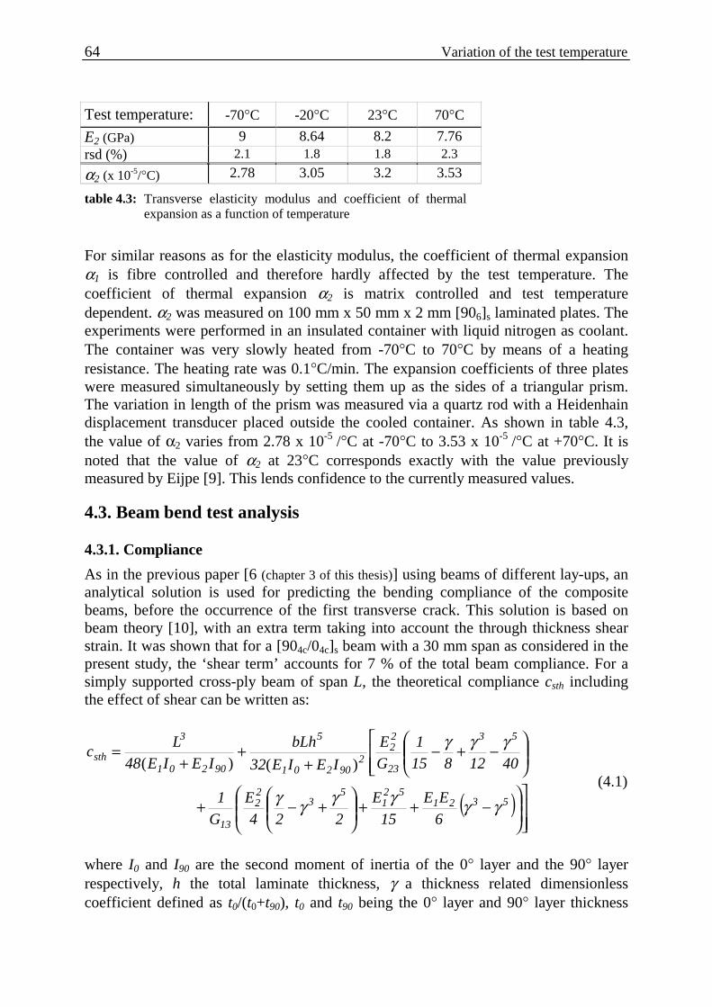
64 Variation of the test temperature
Test temperature: -70°C -20°C 23°C 70°C
E2 (GPa) 9 8.64 8.2 7.76 rsd (%) 2.1 1.8 1.8 2.3
α2 (x 10-5/°C) 2.78 3.05 3.2 3.53
table 4.3: Transverse elasticity modulus and coefficient of thermal expansion as a function of temperature
For similar reasons as for the elasticity modulus, the coefficient of thermal expansion α1 is fibre controlled and therefore hardly affected by the test temperature. The coefficient of thermal expansion α2 is matrix controlled and test temperature dependent. α2 was measured on 100 mm x 50 mm x 2 mm [906]s laminated plates. The experiments were performed in an insulated container with liquid nitrogen as coolant. The container was very slowly heated from -70°C to 70°C by means of a heating resistance. The heating rate was 0.1°C/min. The expansion coefficients of three plates were measured simultaneously by setting them up as the sides of a triangular prism. The variation in length of the prism was measured via a quartz rod with a Heidenhain displacement transducer placed outside the cooled container. As shown in table 4.3, the value of α2 varies from 2.78 x 10⁻⁵ /°C at -70°C to 3.53 x 10⁻⁵ /°C at +70°C. It is noted that the value of α2 at 23°C corresponds exactly with the value previously measured by Eijpe [9]. This lends confidence to the currently measured values.
4.3. Beam bend test analysis
4.3.1. Compliance
As in the previous paper [6 (chapter 3 of this thesis)] using beams of different lay-ups, an analytical solution is used for predicting the bending compliance of the composite beams, before the occurrence of the first transverse crack. This solution is based on beam theory [10], with an extra term taking into account the through thickness shear strain. It was shown that for a [904c/04c]s beam with a 30 mm span as considered in the present study, the ‘shear term’ accounts for 7 % of the total beam compliance. For a simply supported cross-ply beam of span L, the theoretical compliance csth including the effect of shear can be written as:
( )
−++
+−+
−+−
++
+=
532152
15
322
13
53
23
22
290201
5
90201
3
sth
6
EE
15
E
224
E
G
1
4012815
1
G
E
IEIE32
bLh
IEIE48
Lc
γγγγγγ
γγγ)()(
(4.1)
where I0 and I90 are the second moment of inertia of the 0° layer and the 90° layer respectively, h the total laminate thickness, γ a thickness related dimensionless coefficient defined as t0/(t0+t90), t0 and t90 being the 0° layer and 90° layer thickness

Chapter 4 65
respectively. G13 and G23 are the out-of-plane shear moduli. The material is assumed transversally isotropic and therefore:
)1(2;
23
2231213 ν+
== EGGG
with ν23 the transverse out-of-plane Poisson ratio.
4.3.2. Thermal residual stress
4.3.2.1. Quantification after manufacture
As discussed previously in [5 (chapter 2 of this thesis)], the build up of thermal stresses starts during fabrication of the laminate when it is cooled down from the stress free temperature to room temperature. The stress free temperature in the case of an amorphous thermoplastic is taken as the glass transition temperature [11] ( gT of the
polyetherimide used is 215°C). On a fibre-matrix scale, the contraction of the matrix (αm=57 x 10-6 /°C) is constrained by the presence of the fibre (αf = -1 x 10⁻⁶ /°C). This results in residual stresses on a fibre-matrix scale (microscale). As follows from table 4.2, the properties of a carbon-polyetherimide unidirectional layer can be considered transversally isotropic. This means that a multidirectional composite will not only contain stresses on a microscale, but also on a ply-to-ply (macroscopic) basis. The residual stresses on the macroscopic scale are often calculated with the 2D in-plane classical laminate theory [12] (CLT). The limitation of the CLT is that each ply is assumed to be in a state of plane stress and that interlaminar stresses are neglected. This does not affect the quantification of the residual stresses in symmetric lay-ups. The expression for the residual stress in the 90° layer of a cross-ply [0/90]s laminate according to the CLT is [5 (chapter 2 of this thesis)]:
:with)(*,
)(*,
)(*,
CLT902r
9012
CLT901r
9011
CLT901r QQ −−− += εεσ (4.2)
TAAA
NANAT
AAA
NANA12
122211
T212
T111CLT90
2r22122211
T212
T122CLT90
1r ∆−−
−=∆−−
−= −− αεαε )(*,
)(*, ;
( )
( )
21290
210
2190
120
1220
2290
11190
220
11
0j
0ij
90j
90ij
Ti
0ij
90ijij
EQQQQEQQEQQ
21jiQ1QhTN
21jiQ1QhA
ψνψψ
γαγα
γγ
========
=+−∆=
=+−=
)()()()()()()()(
)()()()(
)()(
;;
,,;)(
,,;)(:with
900
0
1
21221
2112 tt
t
E
E
1
1
+==
−= γνν
ννψ ;;:and

66 Variation of the test temperature
where ),(*
900ijQ are the components of the reduced stiffness matrix of the 0o or the 90o
layer in the laminate coordinate system (*). Aij are the components of the laminate
stiffness matrix and TiN the thermal force components due to the temperature change
∆T. The value of the factor ψ is around 1.01 for unidirectional layers and has been taken equal to unity. With the thermo-mechanical properties of table 4.2 and a temperature difference ∆T of
-192°C (i.e. cooling from 215°C to 23°C), the CLT predicts a value )(*,
901rσ of 43.5 MPa
for a cross-ply [904c/04c]s.
4.3.2.2. Stress relaxation between times of manufacture and testing
Between manufacturing and testing, relaxation of the residual stresses will occur in the cross-ply laminate due to the viscoelastic properties of the matrix. Measurements aimed at evaluating the relaxation on the system at 23°C were presented in a previous publication [5 (chapter 2 of this thesis)]. The results, which are relevant to the present study, are summarised in this sub-section. Beside the relaxation measurements, a model was proposed, based on a micro-mechanical model. Use was made of the manufacturer’s polyetherimide creep data and the linear-elastic properties of the carbon fibre. The experiments showed a 24 % reduction in stress after 240 hours for a [904c/04c]s cross-ply laminate. The model used predicted a 14 % decrease over the same period. The observation of time dependent matrix cracking during the relaxation testing led to the conclusion that the measured relaxation was not solely the result of the viscoelastic effects. The presence of matrix cracks or micro-cracking was thought to cause the decrease in stiffness of the 90° layer [13] and thus the additional decrease in residual stress. Although both mechanisms contribute to the decrease in thermal stresses, the viscoelasticity-induced part of the measured relaxation is recoverable and has no influence on the actual stiffness of the 90° layer. It is proposed to use the micro-mechanical model of [5 (chapter 2 of this thesis)] as a first approximation of the viscoelasticity induced relaxation. A reduction factor fv reflects the reduction of the residual stress level. The following relation defines the relaxed residual stress in the 90° layer.
)(*,
)(*, )()( 90
1rv90
1rr tft σσ = (4.3)
The factor fv depends on both time and initial level of residual stresses. For the [904c/04c]s cross-ply laminate used in this study, fv can be approximated by the following power law [5 (chapter 3 of this thesis)]:
0190901r
v t841
tf .)(
*,
.)( −=
σ (4.4)

Chapter 4 67
With the time t in hours and )(*,
901rσ =43.5 MPa. (see section 4.3.2.1).
4.3.2.3. Thermal residual stresses at the time of testing
The build-up of the axial residual stress in the 90° layer of a cross-ply beam is sketched in figure 4.1 as a function of time from fabrication to testing. The level of
residual stress just after fabrication, )(*,
901rσ , is determined with equation (4.2) with a ∆T
of -192°C (23°C-215°C). The residual stress then relaxes at room temperature (23°C)
and the resulting )(*,
901rrσ is calculated as a function of time with equation (4.3). It was
decided to perform the bending tests after the residual stress relaxation was reasonably stabilised. A time of 240 hours between fabrication and testing was judged to be sufficient. When testing at room temperature (23°C) 240 hours after fabrication, the amount of axial residual stress is equal to:
)(*,
)(*,
)(*, )()( 90
1rv90
1rr901rt h240fh240 σσσ ==
When testing at the three other temperatures (-70°C, -20°C, 70°C), an extra term needs to be added for the thermal stress induced by the temperature difference between room temperature and the test temperature:
23TTwithTh240 test901r
901rr
901rt −=∆∆+= )(
*,)(*,
)(*, )( σσσ (4.5)
where )(*,
901rσ is calculated with equation (4.2).
The path of residual stress development from fabrication to the instance of testing at the four different test temperatures is shown in figure 4.1, and the corresponding values in table 4.4.
4.3.3. The bending stress
A relationship for the bending stress at the bottom of the 90° layer of the [904c/04c]s laminated beam is obtained from beam theory [10]:
],[)(
)/()()(
*, 2t2t2tzforIEIE2
Ezd2LFz 9000
90201
2901b +∈
+−
=σ (4.6)
where d is the longitudinal distance between the crack plane and the vertical axis through the loading nose as shown in figure 4.2. This distance has to be included to calculate the actual bending stress where the crack forms, since the bending moment is not constant over the length of the beam. The bending stress is maximum at the beam free surface, (i.e. for z=h/2 with h the total beam thickness) and this is where the transverse crack is supposed to initiate.

68 Variation of the test temperature
25
30
35
40
45
50
55
60
0 50 100 150 200 250 300
Time (h)
(90)
Res
idua
l str
ess
σr,
1* (
MPa
)
)(*,
901rσ
)()(*, h24090
1rrσ
After fabrication:
After 240h relaxation at 23oC:
)(*,
901rtσTesting : at: -70oC:
-20oC:
23oC:
70oC:
figure 4.1: Time evolution of the residual thermal stress in the 90° layer of a cross-ply
laminate, from fabrication until testing (at different test temperatures).
Test Temp.(°C) -70°C -20°C 23°C 70°C Thermal stress
)(*,
901rtσ (MPa) 56.7 47.2 37.6 26.9
table 4.4: Residual stress at the different test temperatures.
4.4. Experimental programme
4.4.1. Specimen preparation
Both specimens with [906c]s and [904c/04c]s lay-up were tested at -70°C, -20°C, 23°C and 70°C. The beam specimens were cut with a water-cooled diamond saw from different locations in the plates for statistical analysis. The specimens were cut directly after pressing. The results at 23°C for both unidirectional and cross-ply specimens are reproduced from an earlier paper [6 (chapter 3 of this thesis)]. For the tests at the other temperatures, the specimens were cut from the same plates as for the tests at 23°C. Only one laminate was used for the unidirectional specimens. For the cross-ply beams, 5 laminates, coded from (a) to (e), were used at room temperature. The beam specimens from the fifth plate (e) were cut with the help of a low pressure carbon saw, leading to a better cutting surface finish. The test specimens for testing at the other temperatures were taken from the laminates (a) and (b). At least 8 specimens per test temperature were used as shown in table 4.5.

Chapter 4 69
Testing T (°C): -70 -20 23 70
[906c]s 12 10 12 11
[904c/04c]s 8
(laminate b) 8
(laminate b) 40
(laminates (a to d) 13
(laminate a & b)
table 4.5: Number of beam specimen tested per type of lay-up and temperature.
A few cross-ply specimens had some obvious transverse cracks in the 90°layer before the actual test and were not tested. The cut specimens were conditioned at 23oC and 50% relative humidity until testing. An arbitrary time of 240 hours after fabrication was chosen for the bending tests [5 (chapter 2 of this thesis)].
4.4.2. Experimental set-up.
All experiments were performed on a screw driven Zwick testing machine fitted with a three point bend set-up, at a constant cross-head velocity of 1 mm/min, which corresponds to a strain rate at the bottom of the beam of 2.4x10⁻⁴ /s for the 16 layer cross-ply beam. The span L used was 30 mm, with 5 mm diameter cylindrical fixed supports, and a 9.5 mm diameter cylindrical loading nose. The beams were around 50 mm long and nominally 12 mm wide (b), the precise width being measured for each specimen. The compact test set-up was placed in a temperature controlled environment chamber. Temperatures below room temperature were created with a controlled injection of liquid nitrogen.
45oy
xz
L
b
h
d
(a) (b)
t90 /2
t0
figure 4.2: Dimensions of the three point bending set-up.
4.4.2.1. Measurement of the beam deflection
The deflection of the beam was monitored with an inductive displacement gauge (Mahr Pupitron) with a sensitivity of 0.06 mm/V. In the case of the tests at room temperature, the transducer measured the deflection at the bottom side of the beam, directly under the loading nose main axis. For the other test temperatures, the

70 Variation of the test temperature
displacement had to be measured outside the environmental chamber and the transducer measured the actual displacement of the machine cross-head. Measuring the deflection locally prevents taking into account the influence of the indentation of the loading nose on the global beam deflection. The indentation of the supports on the beam was shown to be negligible [6 (chapter 3 of this thesis)]. For the tests in the environmental chamber, it is then necessary to determine the system compliance, which mostly concerns the quantification of the influence of the local indentation of the supports and the loading nose on the global deflection of the beam. For this purpose, a number of beams was tested with the two supports set close together to obtain a minimum span length, as shown in figure 4.3-b.
F (N)
XZ
FF δb
δ (mm)
Indentation testBending test
Bending test
Indentation test
δbδi
Fa
δi
0.270.013
150
(a) (b)
(c)
figure 4.3: Bending test and indentation test.
In this way, the global bending deflection of the beam is minimised compared to the indentation of the supports. Typical force-displacement responses of both bending and indentation tests are shown in figure 4.3-c. At a certain force Fa, the corrected deflection is obtained by subtracting the displacement δi corresponding to the indentation test from the displacement δb measured during the actual bending test. The values quoted on the force-displacement diagram in figure 4.3 are indicative of the system compliance corrections made.

Chapter 4 71
Based on 5 indentation tests, the indentation compliance was determined as 5 % of the bending compliance of a cross-ply beam. This correction is applied in all calculations. For the unidirectional laminate, the indentation compliance was less than 1 % of the bending compliance and is therefore neglected.
4.4.2.2. Detection of the transverse crack
The detection of the transverse cracking was relatively easy because the 90° layer was the outer layer. For the specimens tested at the 2 lowest temperatures, the transverse crack growth was unstable and a substantial amount of energy was released at crack formation. This led to a significant force drop, as shown in figure 4.4 for a typical force-displacement response at -70°C. In this case, the test was interrupted so that the distance d in relation (4.6) between the crack plane and the loading nose axis could be measured.
0
50
100
150
200
250
0 0.1 0.2 0.3 0.4 0.5 0.6
Deflection (mm)
Forc
e (N
)
-70oC+70o
figure 4.4: Typical force-displacement response of two cross-ply laminated beams tested at -70°C and
+70°C
At 70°C, the crack growth was mostly stable and no force drop was noticeable as shown in figure 4.4. At 23°C, the crack growth was either stable or unstable. For these two temperatures, a visual technique was therefore used for the crack detection. Cracking was recorded by a CCD camera connected to a time-coded video recorder. The video time base was synchronised with that of the data acquisition system monitoring the force and displacement. The recording occurred through an optical mirror placed under the beam as sketched in figure 4.2. The mirror was fixed to the loading nose in order to keep the sharpness of the picture during the test. Based on the video record, the longitudinal distances (d in relation (4.6)) between the resulting transverse crack plane and the loading nose axis could be measured by viewing the video recording after testing. For this purpose, a X-Y table fitted with a travelling microscope was used.

72 Variation of the test temperature
4.4.3. Results
4.4.3.1. Compliance before the occurrence of the first visible transverse crack
The bending compliance, cexp, prior to the occurrence of the first transverse crack is obtained from the inverse slope of the measured force-displacement response. The results obtained with the unidirectional beams provide the transverse elasticity moduli at different temperatures as presented in table 4.3. These values are used to predict the compliance of the cross-ply beams with equation (4.1). A summary of the bending compliances of the cross-ply beams is presented in table 4.6. The first two rows give the test temperature and the number, n, of specimens tested. The letters (a) to (e) are used to differentiate between the laminates having the same lay-up. The next rows give
the level of internal stresses, )(*,
901rtσ , as determined in section 3.2.3 and the average
ratio between the theoretical compliance including the shear effect, csth, (relation (4.1)) and the experimental compliance cexp. Also the relative standard deviation, rsd, of the compliance ratio is given. Test T (°C) -70 -20 +23
(a) (b) (c) (d) (e) +70
(a) (b) Number of specimens n 8 8 7 8 12 7 8 6 7
Thermal stress
)(*,
901rtσ (MPa)
56.7 47.2 37.6 26.9
Average ratio theoretical/ Experimental compliance
∑=
n
1ii
isth
n1
c
c)(
exp
)(
0.88 0.91 0.95 0.91 0.87 0.95 0.97 0.99 0.97
Rsd (%) 8.5 5.7 6.6 7.8 9.5 5.9 1.6 4.5 4.6
table 4.6: Summary of the cross-ply beams bending compliances.
The complete set of data is depicted in figure 4.5, giving the compliance ratios csth/cexp and the average value as a function of the residual stress. In spite of the scatter in the data, the results clearly reveal that the predicted compliance underestimates the measured one within the range of test temperatures considered. The difference between the two compliances increases with increasing residual stress. These results confirm the conclusions drawn in an earlier publication by the present authors [6 (chapter 3 of this thesis)], where the level of residual stress was varied by testing cross-ply beams having different lay-ups at room temperature. That study showed the existence of a residual stress limit above which the theoretical compliance underestimates the measured compliance. The residual stress limit

Chapter 4 73
proposed in that paper of 25-30 MPa for the system considered also applies to the present data.
0.5
0.6
0.7
0.8
0.9
1.0
1.1
25 30 35 40 45 50 55 60
Residual stress (MPa)
Com
plia
nce
ratio
cst
h/c
exp
-70oC -20oC +23oC +70oC Average
)(*,
901rtσ
figure 4.5: Bending compliance ratio csth/cexp as a function of the relaxed residual stresses.
It was argued in [6 (chapter 3 of this thesis)] that the increase in compliance with increasing residual stress could be attributed to the presence of damage on a fibre-matrix level which occurred before mechanical testing. This damage would decrease the stiffness of the 90° layer and therefore increase the compliance of the beam. This micro-damage can also induce early transverse cracking. Evidence of transverse cracks before testing in the cross-ply beams was observed in the present test series. The high relative standard deviation also strengthens the argument that a damage process controls the measured compliance. Such observations were also made in the laminated plates used for determining the residual stress relaxation [5 (chapter 2 of this thesis)]. By assuming that the above mentioned micro-damage is uniformly distributed across the laminate, the composite layer can still be treated as being transversally isotropic. It makes it possible to translate the experimental bending compliance into material properties, namely the elasticity moduli of layers containing micro-damage. It is also assumed that the elasticity modulus in the fibre direction will hardly be affected by the micro-damage of the matrix. The increase in the experimentally observed compliance therefore finds its origin in the 90° layer. An “apparent” transverse elasticity modulus E2d can therefore be calculated by replacing the compliance csth in relation (4.1) by the measured compliance cexp and solving for E2d [6 (chapter 3 of this thesis)]. The results for the different test temperatures are given in table 4.7. As a reference, the level of thermal stress and the “undamaged” transverse elasticity moduli E2 obtained from the bending testing of the unidirectional [906c]s beams are given.

74 Variation of the test temperature
Test T: (°C) -70 -20 +23 (a) (b) (c) (d) (e)
+70 (a) (b)
Thermal stress )(*,
901rtσ (MPa) 56.7 47.2 37.6 26.9
Transverse elasticity modulus (table 4.3) E2 (GPa)
9 8.64 8.2 7.76
Apparent transverse elasticity modulus E2d (GPa)
6.07 6.51 6.94 6.88 5.03 6.92 7.54 7.16 6.78
rsd (%) 31.3 20.9 23 27.1 39.4 20.6 5.2 15.4 16.1
∆E2 (%) -32 -24.6 -15.4 -16.1 -38.7 -15.6 -8 -7.7 -12.6
table 4.7: Apparent transverse modulus E2d results
Obviously, the apparent transverse modulus, E2d, is always less than E2. The relative standard deviation tends to increase with increasing residual stress. Although the scatter on the results is high, the difference between the two transverse moduli tends to increase with increasing residual stress. It can be seen that the higher level of internal stresses reached at the lower test temperature increases the amount of assumed micro-damage, giving rise to the altered properties. As noticed in a previous article [6 (chapter 3 of this thesis)], the results obtained with the beam specimen cut with the low-pressure metallurgical saw (series (e) at 23°C) have a lower scatter. These beams are also the least affected by the pre-testing damage mechanism (7.5 GPa compared to 8.2 GPa). This suggests that the micro-damage induced by the residual stresses can be initiated at the free edges of the beam. This observation will be discussed in more details in a subsequent publication [14 (chapter 5 of this thesis)].
4.4.3.2. Stress at the formation of the first transverse crack
The crack formation appeared to be unstable for tests at the lowest test temperature and most of the tests at 23°C. At 70°C, the crack formation was stable and did not lead to any sudden force drop. In most of these cases, it could be observed that the crack started to form at one of the edges of the beam. In the case of the cross-ply beams, the
stress normal to the crack plane is equal to the thermal residual stress )(*,
901rtσ (relation
(4.5)) plus the mechanical bending stress )(*,
901bσ at z = h/2, the outer face of the beam,
where the crack is most likely to initiate (relation (4.6)). This leads to:
)()(*,
)(*,
)(*, 2h90
1b90
1rt90
1ftc σσσ += (4.7)
The stresses are evaluated using first E2 and then E2d for the transverse modulus value. For the series at 23°C and 70°C, the value of E2d was averaged over the complete sample of tested laminates (6.48 MPa and 6.95 MPa respectively). Since it is assumed that the apparent modulus reflects the increase in compliance due to the presence of micro-damage, it is also used to calculate the residual stress. The results for both

Chapter 4 75
thermal and bending stresses using both elasticity moduli are given in table 4.8 as averages for the sets of specimens from each plate.
The resulting total stress at first transverse crack, )(*,
901ftcσ , based on both transverse
moduli are shown in table 4.9. The row referred to as ∆ )(*,
901ftcσ relates to the difference
in total stress when using the standard transverse modulus E2 or the apparent transverse modulus E2d. This table also gives the results obtained from the unidirectional [906c]s beams. Test T: (°C) -70 -20 +23
(a) (b) (c) (d) (e) +70
(a) (b) )(*,
901rtσ
(with E2) 57.4 47.3 37.6 26.4
Res
idua
l st
ress
(M
Pa)
)(*,
901rtσ
(with E2d) 44.3 37.6 30.4 20.3
)(*,
901bσ
(with E2) 28.5 34.6 31.4 32.6 31 33 33.7 31.3 32
Ben
ding
st
ress
(M
Pa)
)(*,
901bσ
(with E2d) 21.7 28.5 26.7 28 26.3 28 28.6 29 29.6
rsd (%) 20.7 19.4 4.7 17.5 10.7 16.9 11.3 5.6 14.7
table 4.8: Residual and bending stresses at the initiation of the first transverse crack in the cross-ply specimens.
Test T: (°C) -70 -20 +23
(a) (b) (c) (d) (e) +70
(a) (b) )(*,
901ftcσ 91.3 79.5 70.4 58.3
[90 6
c]s
rsd (%) 12.7 13.1 9.1 9.4
)(*,
901ftcσ
(with E2) 85.9 81.9 69 70.2 68.6 70.6 71.3 57.7 58.4
)(*,
901ftcσ
(with E2d) 66 66.4 57.1 58.4 56.7 58.4 59 49.2 49.9
∆ )(*,
901ftcσ (%) -23 -19 -17 -15
[90 4
c/0 4
c]s
rsd (%) 6.9 8.2 2.1 8.2 5 7.9 5.5 3.1 8
table 4.9: Total stress at the initiation of the first transverse crack
The detailed results of the stress at first transverse crack are plotted as a function of the residual stress in figure 4.6 and 4.7. The average stress at fracture of the unidirectional beams at the corresponding temperature is shown in these figures as well. It is worth noting that these latter values only correspond to a test temperature, and not to a level of residual stress, as ply-to-ply residual stresses are zero in unidirectional laminates.

76 Variation of the test temperature
0
20
40
60
80
100
15 20 25 30 35 40 45 50 55 60
Residual stress (MPa)
Stre
ss a
t ftc
σft
c,1*
(M
Pa)
-70oC -20oC : Average [906c]s strength at the corresponding temperature.
+70o Average
(90)
Using the transverse elasticity modulus E 2
)(*,
901rtσ
+23o
figure 4.6: Axial stress at first transverse crack as a function of the relaxed residual stress
0
20
40
60
80
100
15 20 25 30 35 40 45 50 55 60
Residual stress (MPa)
Stre
ss a
t ftc
σft
c,1*
(M
Pa)
: Average [906c]s strength at the corresponding temperature.-70oC -20oC +23o +70o Average
Using the apparent transverse elasticity modulus E 2d
(90)
)(*,
901rtσ
figure 4.7: Axial stress at first transverse crack as a function of the relaxed residual stress based on the
apparent transverse modulus
For both unidirectional and cross-ply lay-up, the stress at the formation of the first transverse crack decreases with increasing test temperature. For the unidirectional beams, the stress at failure decreases almost linearly from 91 MPa at –70°C to 58 MPa at +70°C. Using the apparent transverse modulus E2d instead of the “standard” transverse modulus E2 for the cross-ply specimens, clearly leads to a decrease in the
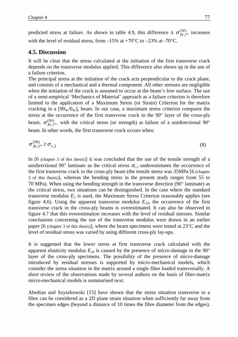
Chapter 4 77
predicted stress at failure. As shown in table 4.9, this difference ∆ )(*,
901ftcσ increases
with the level of residual stress, from –15% at +70°C to –23% at -70°C.
4.5. Discussion It will be clear that the stress calculated at the initiation of the first transverse crack depends on the transverse modulus applied. This difference also shows up in the use of a failure criterion. The principal stress at the initiation of the crack acts perpendicular to the crack plane, and consists of a mechanical and a thermal component. All other stresses are negligible when the initiation of the crack is assumed to occur at the beam’s free surface. The use of a semi-empirical ‘Mechanics of Material’ approach as a failure criterion is therefore limited to the application of a Maximum Stress (or Strain) Criterion for the matrix cracking in a [904c/04c]s beam. In our case, a maximum stress criterion compares the stress at the occurrence of the first transverse crack in the 90° layer of the cross-ply
beam, )(*,
901ftcσ , with the critical stress (or strength) at failure of a unidirectional 90°
beam. In other words, the first transverse crack occurs when:
2,)90(*1, cftc σσ ≥ (8)
In [6 (chapter 3 of this thesis)] it was concluded that the use of the tensile strength of a unidirectional 90° laminate as the critical stress σc,2 underestimates the occurrence of the first transverse crack in the cross-ply beam (the tensile stress was 35MPa [6 (chapter 3 of this thesis)], whereas the bending stress in the present study ranges from 55 to 70 MPa). When using the bending strength in the transverse direction (90° laminate) as the critical stress, two situations can be distinguished. In the case where the standard transverse modulus E2 is used, the Maximum Stress Criterion reasonably applies (see figure 4.6). Using the apparent transverse modulus E2d, the occurrence of the first transverse crack in the cross-ply beams is overestimated. It can also be observed in figure 4.7 that this overestimation increases with the level of residual stresses. Similar conclusions concerning the use of the transverse modulus were drawn in an earlier paper [6 (chapter 3 of this thesis)], where the beam specimens were tested at 23°C and the level of residual stress was varied by using different cross-ply lay-ups. It is suggested that the lower stress at first transverse crack calculated with the apparent elasticity modulus E2d is caused by the presence of micro-damage in the 90° layer of the cross-ply specimens. The possibility of the presence of micro-damage introduced by residual stresses is supported by micro-mechanical models, which consider the stress situation in the matrix around a single fibre loaded transversally. A short review of the observations made by several authors on the basis of fibre-matrix micro-mechanical models is summarised next. Abedian and Szyszkowski [15] have shown that the stress situation transverse to a fibre can be considered as a 2D plane strain situation when sufficiently far away from the specimen edges (beyond a distance of 10 times the fibre diameter from the edges).

78 Variation of the test temperature
At the edges of the laminate, a 3D model has to be applied. In this case, the axial shrinkage of the matrix at the end of the fibre induces a high local radial stress at the fibre-matrix interface. It was argued that this stress was sufficient to produce crack initiation in a carbon-epoxy system. The model presented in [15] supported experimental data by Morris, Inman and Cox [4]. Based on the carbon-polyetherimide composite used in the present study, a 2D plane strain model of a fibre embedded in matrix is presented in [5 (chapter 2 of this thesis)]. The aim was to support the occurrence of micro-damage or even matrix cracks under the presence of residual stress. Since no data on the fibre-matrix interface of the carbon-polyetherimide system were available, two extreme situations were studied: one with a perfect interface and the other with no interface between the fibre and the matrix. The maximum von Mises stress predicted in the matrix near the fibre-matrix interface varied between 64 MPa and 122 MPa for respectively a perfect interface and no interface. Because the yield stress of the matrix is 105 MPa [16], it was concluded that crazes could form in regions of poor fibre-matrix interface. For the tests performed in the present study, the dependence of the matrix properties on the test temperature have been taken into account in further modelling. A similar model as in [5 (chapter 2 of this thesis)], where the residual stress situation is considered at the beginning of the test, was used with the different test temperatures. The resulting von Mises stresses, σvM, for the case when no fibre-matrix interface is assumed are given in table 4.10, together with the elasticity modulus, Em, used in the model and the yield stress, σmy, of the polyetherimide matrix [16]. The results show that the increase in von Mises stress with decreasing test temperature goes together with the increase in yield stress of the matrix. This reflects the global increase in strength with decreasing temperature shown in figure 4.6 and 4.7. Furthermore, the last row of table 4.10 shows that the ratio between the maximum von Mises stress and the yield stress of the matrix σvM/σmy increasingly exceeds unity with decrease in temperature, thus increasing the probability of crazing and micro-damage. Test T: (°C) -70 -20 +23 +70
PEI elasticity modulus Em (GPa) [16]
3.5 3.28 3 2.55
PEI yield stress σmy (MPa) [16] 162 134 105 83
Max von Mises stress σvM (MPa)
210 162 122 78
∆ σvM/σmy (%) +29 +21 +16 -6
table 4.10: Maximum von Mises stress calculated in a micro-mechanical fibre-matrix model.

Chapter 4 79
4.6. Conclusion In this paper the influence of the level of ply-to-ply thermal residual stresses on the transverse cracking of cross-ply [904/04]s carbon-polyetherimide laminated beams subjected to bending has been considered. The different levels of residual stresses were obtained in the current work by varying the test temperature (-70°C, -20°C, 23°C, 70°C). Several observations can be made on the basis of the results obtained. The ratio between the theoretical and the experimental bending compliance of the cross-ply beam specimens before the occurrence of the first transverse crack tends to decrease with increasing residual stress. It is argued that this difference is due to the formation of micro-damage on a fibre-matrix scale, which can be interpreted by use of an apparent transverse modulus E2d derived from the bending measurement. The stress at the occurrence of the first transverse crack consists of the residual stress and the bending stress. It was observed that this stress increases with decreasing temperature and therefore with increasing residual stress. Part of this increase is clearly due to the dependence of the temperature on the composite properties, in a direction perpendicular to the fibres. Furthermore, a difference in the calculated stress at failure of up to 23% at the lowest test temperature is obtained when using the apparent transverse modulus E2d for the calculation, instead of the transverse modulus E2 measured from the unidirectional specimens. The choice of a transverse modulus value used has consequences for the application of a strength-based failure criterion. The criterion (using the strength of a unidirectional beam as a reference) applies for the structure considered when using the transverse modulus as measured on a unidirectional beam. When using the apparent modulus, the criterion predicts the occurrence of the first crack at a lower stress level. It is worth adding that this reduction increases with increasing thermal stress. Hence the probability of micro-damage formation in the matrix increases as the temperature is decreased and the residual stress increases.

80 Variation of the test temperature
References 1. Pegoraro, M.; Di Landro, L.; “Influence of components and interface conditions on mechanical
properties of composites and blends”; Makromolekulare Chemie, Macromolecular Symposia, Vol. 70/71 (1993), p. 193-212.
2. Liu, S., Nairn, J.A.; “The formation and propagation of matrix microcracks in cross-ply laminates during static loading”; J. of Reinforced Plastics and Composites, Vol.11 (1992), p. 158-178.
3. Nairn, J.A., Zoller, P.; “The development of residual thermal stresses in amorphous and semicrystalline thermoplastic matrix composites”, Toughened Composites, ASTM STP 937, Johnston, N.J., Ed. (1987), p. 328-341.
4. Morris, W.L, Inman, R.V, Cox, B.N.; “Microscopic deformation in a heated unidirectional graphite-epoxy composite”; J. of Materials Science, Vol.24 (1989), p. 199-204.
5. Warnet, L., Reed, P.E., Akkerman, R; “On the relaxation of thermal residual stresses and related damage in Carbon-Polyetherimide laminates”; prepared for publication.
6. Warnet, L., Reed, P.E., Akkerman, R; “The effect of residual stress on transverse cracking in cross-ply Carbon-Polyetherimide laminates under bending: Variation of the laminate lay-up”; prepared for publication.
7. Gibson, R.F.; “Principles of composite materials mechanics”, McGraw-Hill (1994). 8. Caruso, J.J., Chamis, C.C.; “Assessment of simplified composite micromechanics using three-
dimensional finite element analysis”, J. of Composites Technology & Research, Vol. 8 (1986), p. 77-86.
9. Eijpe, M.P.I.M.; “A modified layer removal method for determination of residual stresses in Polymeric composites”; PhD Thesis, University of Twente (NL), ISBN 9036510155 (1997).
10. Gere, J.M., Timoshenko, S.P.; “Mechanics of materials”, Chapman & Hall (1991) 11. Nairn, J.A., Zoller, P.; “Matrix solidification and the resulting residual thermal stresses in
composites”, J. of Materials Science, Vol. 20 (1985), p. 355-367. 12. Eijpe, M.P.I.M., Powell, P.C;“A modified layer removal analysis for the determination of
internal stresses in polymer composites”, J. of Thermoplastic Composite Materials, Vol. 10, (1996), p. 145-151.
13. Hahn, H.T., Tsai, S.W.; “On the behavior of composite laminates after initial failures”; J. of Composite Materials, Vol. 8 (1974), p. 288-305.
14. Warnet, L., Reed, P.E., Akkerman, R; “On the effect of residual stress on the transverse cracking of cross-ply Carbon-Polyetherimide laminated plates loaded transversally”; prepared for publication.
15. Abedian, A., Szyszkowski, W.; “Influence of the free surface on the thermal stresses in unidirectional composites”; Composites Part A, Vol. 28A (1997), p. 573-579.
16. ULTEM 1000 data sheets, CAMPUS 4.0, GE Plastics Europe (1996).

Chapter 5 81
Chapter 5
On the effect of thermal residual stresses on the transverse cracking of carbon-polyetherimide composite plates loaded transversally
5.1. Introduction Transverse cracking is generally recognised as the first damage mechanism occurring in a composite laminated structure subjected to impact loading [1,2,3]. These cracks run parallel to the fibres through the layer thickness. Their formation is mostly not dramatic for the integrity of the structure. However, they will affect the thermo-mechanical properties of the structure [4,5] and provide open paths for environmental degradation [6]. Transverse cracking will furthermore act as a trigger for further damage mechanisms like delamination [3,7]. Warnet, Reed and Akkerman [8,9 (chapters 3 and 4 of this thesis)] have published on the effects of thermal residual stress on transverse cracking in carbon reinforced thermoplastic laminated beams ([904/04]s) subjected to three-point bending. They varied the level of residual stress by (a) changing the lay-up of the laminated beam [8 (chapter 3 of this thesis)] and (b) the test temperature [9 (chapter 4 of this thesis)]. They argued that a residual stress threshold level exists for the carbon-polyetherimide system examined, above which micro-damage is induced on a fibre-matrix scale, even before any mechanical loading is applied. The effect of such thermal stress induced damage was noticed in the measured increase in bending compliance of the laminated beam, before the formation of the first transverse crack and in the decrease in applied stress required for the formation of the first crack. An important question remaining was the effect of the beam free edges on the behaviour noticed. It was shown experimentally by Morris, Inman and Cox [10] that stress concentrations due to thermal stresses acting on the fibre-matrix interface at the edge of a specimen can lead to local micro-cracking at the fibre-matrix interface. This edge effect is restricted to the fibre-matrix interaction within a layer. It differs from the edge effect usually mentioned in the literature [11,12], which deals with macroscopic interlaminar shear and out-of-plane stresses in multi-layer laminates loaded under tension. This study concerns the influence of the specimen edges at the formation of the first transverse crack. For this purpose, two different geometries were tested under quasi-static loading conditions, namely, (a) square laminated plates on a circular support loaded centrally by a spherical indenter and (b) laminated beams subjected to three-point bending loading. An obvious reason for the choice of the plate geometry is that the transverse crack initiates under the central load, far from the plate edges. The carbon-polyetherimide material was used, as in the previous studies [8,9,13 (chapters 3, 4 and 2 of this thesis)]. Two lay-ups were used for studying the influence of ply-to-ply

82 Variation of the laminate geometry
thermal residual stresses, unidirectional transverse [906]s and cross-ply [904/04]s. The 90° layer was chosen as the free-surface layer to facilitate the detection of the formation of the transverse crack with optical techniques. The effect of matrix rich zones at the free surface of the specimens on the cracking behaviour was also considered. The experimental program is first described for both geometries, including the material characterisation and the stress analysis. The results on the measurements of the compliance before cracking and the stress at the formation of the first transverse crack are then presented. The last section discusses the experimental results obtained.
5.2. Experimental program.
5.2.1. Specimen preparation.
The laminates were pressed from polyetherimide (GE Ultem1000)-carbon (Toray T300) unidirectional prepreg manufactured by Ten Cate Advanced Composites. The batch used for the present study differs from the one used for the previous studies by the present authors [8,9,13], but has the same specifications. This prepreg has a 41 % matrix mass fraction, the fibre distribution is not homogeneous and also shows a clear matrix rich zone in the thickness direction. Some attention is therefore required to the location of the matrix-rich layer when building up the laminate. This is illustrated in figure 5.1 and 5.2 with unidirectional laminates built up from 4 layers. The cross-section of the laminate in figure 5.1-a shows that the matrix rich zone of each prepreg layer is laid up towards the free surface of the laminate. The result is shown in a micrograph of the first layer of the resulting laminate in figure 5.1-b. The subscript ‘M’ in the lay-up classification (e.g. [02M]s) stands for ‘matrix rich zone oriented outwards’. Similarly, figure 5.2 shows prepreg layers whose matrix rich zones are oriented towards the inside of the laminate. A subscript ‘F’ is used in the lay-up classification in this case and stands for the ‘fibre rich zone oriented outwards’.
Top layer
Matrix rich zone
(a) (b) figure 5.1: (a): Schematic representation of a [02M]s unidirectional laminate cross-section, showing
the matrix rich zone oriented outwards for each prepreg layer. (b): local micrograph of the top layer of a [02M]s unidirectional laminate
The influence of this through thickness fibre distribution on the transverse cracking behaviour was also evaluated in this study. Since the through thickness distribution of

Chapter 5 83
the fibres will influence the flexural rigidity of the beam or plate, the bending moduli of unidirectional beam specimens were measured in both the fibre direction (E1) and transverse to the fibres (E2). For this purpose, [06F]s, [06M]s, [906F]s and [906M]s beams (50 mm x 12 mm x 2 mm) were cut from two laminates. The bending test set-up used for these tests is described in sub-section 5.2.2.
Top layer
Matrix rich zone
(a) (b) figure 5.2: (a): Schematic representation of a [02F]s unidirectional laminate cross-section, showing the
matrix rich zone oriented inwards for each prepreg layer. (b): local micrograph of the top layer of a [02M]s unidirectional laminate
The bending modulus is calculated using beam theory. In its simplest form, the formulae based on the measured compliance cexp (inverse slope of the force-displacement response) reduces to:
Ic48
LE
3
exp
= (5.1)
where L is the span, I the second moment of inertia (bh3/12), b the beam width and h its total thickness. In the case of the [906]s beam specimens, shear deflection is negligible. Shear deflection needs to be taken into account for the [06]s beams. Assuming that the relation for the deflection of an isotropic beam with shear term given by Gere and Timoshenko [14] can be applied to a unidirectional beam considered transversally isotropic, the expression for the longitudinal modulus E1 can be written as:
IL72IGAc240
LAG5E
13
313
1 −=
exp
(5.2)
where A is the cross-sectional area of the specimen and G13 the through thickness shear modulus. In the case of the [06]s beams and assuming transversal isotropy, G13 is equal to G12. The results for each type of beam are given in table 5.1. All quoted values are all averages based on 8 specimens and are followed by the relative standard deviation in

84 Variation of the laminate geometry
percent. The results of table 5.1 show that the effect of the through thickness fibre distribution is negligible for the flexural rigidity of the [906]s beams (from 8.1 to 8.2 GPa). It accounts for a 4 % difference in the case of the [06]s beams (from 113 to 117 GPa). This is due to the greater difference in elasticity modulus between the fibre and the matrix in the longitudinal direction (230 GPa compared to 3 GPa) than in the transverse direction (14 GPa compared to 3 GPa).
Property: E1 (GPa) E2 (GPa)
Matrix-rich zone outwards ‘M’ 112.9 8.1 rsd (%) 1.4 1.7
Fibre-rich zone outwards ‘F’ 117.2 8.2 rsd (%) 1 1.8
table 5.1: Unidirectional layer bending modulus, using both types of through thickness fibre distributions as described in figure 5.1 and 2.
Other useful thermo-mechanical properties like the shear modulus G12, the coefficients of thermal expansion along the fibre (α1) and transverse to the fibre (α2) are assumed to be independent of the through thickness fibre distribution. These are in-plane properties and, like the tensile elasticity moduli, only depend on the average through thickness matrix fraction, which is assumed constant over the laminate as a first approximation. Here literature values [15] were used as summarised in table 5.2.
Property: G12 (GPa) ν12 ν23 α1 (/oC) α2 (/oC)
3.5 0.32 0.45 1x10⁻⁶ 32x10-6
table 5.2: Thermo-mechanical properties of continuous carbon fibre reinforced polyetherimide [15].
The 250 mm x 250 mm laminates were consolidated by compression moulding according to the procedure described in previous papers [8,9 (chapters 3 and 4 of this thesis)]. The matrix content of the resulting carbon-PEI laminates was measured using a Soxhlet system with chloroform as the matrix solvent. An average of 41.4 % mass matrix fraction (relative standard deviation 2.3 %) was obtained, based on 12 coupons extracted from the bending modulus specimens just mentioned. The average ply thickness was 0.169mm (relative standard deviation 2.9 %). Both beam and plate specimens were cut with a water-cooled diamond saw. The beam and plate specimens were taken from different places in the laminate in order to represent as wide a population as possible within one plate. It was found that the rotating cutting disk induced local delaminations at the free surface of the laminate on the trailing edge. This is illustrated in figure 5.3-a, where the rotating diamond disk is shown, together with the translating support and the laminate being sawn.

Chapter 5 85
Trailing edge
Diamond saw
Support
Laminate
Front viewSide view
(a) (b)
Leading edge
figure 5.3: (a): Sawing set-up. (b): close-up of the unsupported beam free surface
A magnified view of the laminate being sawn in figure 5.3-b shows that a part of the free surface of the laminate is unsupported and loaded under transverse traction by the saw (trailing edge). This is where local delaminations can occur. An example of such a delamination is shown in figure 5.4. No visual defects could be detected on the opposite free surface, which is loaded in transverse compression by the rotating saw (leading edge). It is to be expected that the development of the transverse cracking during testing will be influenced by the presence of such delaminations: the formation of the transverse crack could be triggered earlier by the presence of such a defect. A distinction will therefore be made between the two types of specimens, which will be tested so that transverse cracking either occurs at the sawing trailing edge or at the sawing leading edge. This distinction does not apply to the plate specimen, where the transverse cracking occurs well away from the sawn edges. The specimens of one of the beam series, the unidirectional beams with the fibre rich zone oriented outwards [906F]s, were sawn with a low-pressure metallurgical carbon saw, leading to no visible delaminations on the trailing edge and a smooth sawn surface. The aim was to reduce the damage induced by sawing to a minimum.
1 mm
Beam edge
Edge delamination
figure 5.4: Example of edge delamination induced by the sawing

86 Variation of the laminate geometry
For convenience of the reader, the test variables are summarised here, together with the codes used in the rest of this paper. Geometry: Beam (B) or plate (P). Lay-up: Unidirectional (UD) [906]s or Cross-ply (CP) [904/04]s. Way of laying up: With matrix rich zone towards the specimen free surface (M) or
with the matrix rich zone oriented inwards, which means that a fibre rich zone is situated at the free surface (F).
Testing side: For the beams only, relates to the free-surface edge damage
induced by sawing: the damaged side can be oriented downwards during testing, i.e. on the side where transverse cracking occurs, or upwards, on the opposite side to where transverse cracking occurs. The [906F]s specimens which were to be tested with the damaged side upwards were sawn with a low pressure metallurgical saw.
A minimum of eight specimens per type of condition were tested. The cut specimens were conditioned at 23oC and 50 % relative humidity until testing. The tests were performed 240 hours after fabrication in connection with the relaxation of the thermal residual stresses [13], as will be summarised in section 5.2.2.2.
5.2.2. Beam bend test
5.2.2.1. Set-up
All beam bending experiments were performed on a screw driven Zwick testing machine fitted with a three point bend set-up, at a constant cross-head velocity of 0.5 mm/min. This corresponds to a strain rate at the bottom of the beam of 2.4x10⁻⁴ /s for the 16 layer cross-ply beam. The experimental method adopted for beam testing is as used previously [8 (chapter 3 of this thesis)] and is shown schematically in figure 5.5-a. The span, L, used was 30.2 mm, with 7 mm diameter cylindrical fixed supports and a 9.5 mm diameter cylindrical loading nose. The beams were approximately 50 mm long and nominally 12 mm wide (b), the precise width being measured for each specimen. The force was monitored in order to determine the stress at the formation of the first transverse crack. The beam deflection was recorded in order to calculate the beam compliance. The deflection of the beam was measured with an inductive displacement gauge (Mahr Pupitron) with a sensitivity of 0.06 mm/V. The transducer measured the deflection at the bottom side of the beam, directly under the loading nose main axis. Local measurement of the deflection under the beam avoids the need to correct for the indentation of the loading nose on the beam. It was also shown previously [8 (chapter 3 of this thesis)] that the indentation on the beam at the supports was negligible and could be ignored.

Chapter 5 87
45oy
xz
L
b
h
d
(a) (b)
t90 /2
t0
figure 5.5: (a): Three point bending set-up. (b) Close-up around the transverse crack.
The data required for the analysis are the force, the deflection and the horizontal distance d (figure 5.5-b) between the crack plane and the vertical axis through the loading nose. In the case of the unidirectional [906]s beams, the crack grows in an unstable way through the whole depth of the beam and with clear audible acoustic emission. The determination of the force and displacement values at the occurrence of the first transverse crack in the unidirectional beam is therefore straightforward, as it coincides with the force dropping suddenly to zero, as shown in figure 5.6. For the cross-ply beams, a force drop mostly occurs when the first transverse crack forms, which corresponds with a sudden and unstable crack growth. The crack covers the full width of the beam, but is stopped at the central 0° layer in the thickness direction. The force then increases further until a second crack occurs. A typical example of such a force-displacement response coded “unstable cross-ply” is shown in the figure 5.6. In some cases however, the crack growth was stable and no force drop was noticeable, as shown in a typical force-displacement response coded “stable cross-ply” and where crack initiation is marked by a circle. In this case, the crack initiation cannot be detected by a sudden decrease in the force and optical techniques were used. The detection of the transverse crack was facilitated by the cross-ply lay-up used with the 90° layer as the outer ply. Crack growth was therefore recorded using a CCD camera connected to a time-coded video recorder. As sketched in figure 5.5, the recording occurred through an optical mirror placed under the beam. Analysis of the video record after testing permitted the measurement of the longitudinal distance, d, between the resulting transverse crack plane and the loading nose axis. An X-Y table fitted with a travelling microscope was used for this purpose.

88 Variation of the laminate geometry
0
50
100
150
200
250
300
350
0.0 0.2 0.4 0.6 0.8 1.0
Deflection (mm)
Forc
e (N
)
unstable cross-ply stable cross-ply unidirectional crack initiation
figure 5.6: Typical force-displacement response of 2 cross-ply beams and a unidirectional beam
5.2.2.2. Analysis
• Compliance
The experimental beam compliance, cexp, before the first transverse crack is compared with an analytical solution, csth. In an earlier publication [8 (chapter 3 of this thesis)], an expression taking into account the effect of through thickness shear was developed for the case of a simply supported cross-ply beam of span L:
( )
−++
+−+
−+−
++
+=
532152
15
322
13
53
23
22
290201
5
90201
3
sth
6
EE
15
E
224
E
G
1
4012815
1
G
E
IEIE32
bLh
IEIE48
Lc
γγγγγγ
γγγ)()(
(5.3)
where h is the total beam thickness, γ is a thickness related dimensionless coefficient defined as t0/h, t0 and t90 being the 0° layer and 90° layer thickness respectively, as defined in figure 5.5-b. G13 and G23 are the out-of-plane shear moduli. The material is assumed transversally isotropic and therefore:
)1(2;
23
2231213 ν+
== EGGG
where ν23 is the transverse out-of-plane Poisson’s ratio. In the case of the unidirectional [906]s laminates, equation (3) reduces to the well-known form given in Gere and Timoshenko [14]:

Chapter 5 89
AG10
L3
IE48
Lc
23902
3
sth += (5.4)
where A is the beam cross-sectional area and only G23 is required. The transverse cracking process is basically a Mode I failure. This failure mode is induced by the bending stress and the interlaminar residual thermal stress in the case of the cross-ply lay-up. Although it is recognised that the growth of a transverse crack in a beam is a two-dimensional process [16] (i.e. the crack grows in both the thickness and the width direction), it will be assumed that the crack grows essentially through the thickness as a first approximation. Assuming transversal isotropy, a calculation of the stress component normal to the crack plane due to the residual stresses (figure 5.7-a) and to the bending moment (figure 5.7-b) will be developed next.
σr
+
--
+
+
-σb
(a) (b)
∆T
MM
90o
90o
0o
figure 5.7: Axial stresses in a [904/04]s laminate due to (a): solidification, (b): bending moment
• Thermal residual stresses
The mechanisms and quantification of thermal stress build up during solidification of the laminate have been discussed in previous publications [8,13 (chapters 3 and 2 of this thesis)]. Residual stresses on a fibre-matrix scale (microscopic scale) form as a consequence of the difference in coefficients of thermal expansion of the matrix (56.10-6 /oC) and the carbon fibre (-1.10-6 /oC). A unidirectional composite layer can be assumed transversally isotropic in both mechanical and thermal properties, these properties being determined experimentally. Fabrication of a laminate from unidirectional composite layers having different orientations results in residual stresses on an interlaminar scale (macroscopic scale), due to the restricted thermal contractions of the individual plies. These stresses are computed considering the properties of the transversally isotropic layers and not the individual properties of the fibre and matrix. Equations to calculate the interlaminar residual stresses on the macroscopic scale were previously developed [13 (chapter 2 of this thesis)], based on classical lamination theory

90 Variation of the laminate geometry
(CLT) [17]. These equations will be used in the present work and are reproduced here
for convenience. The residual stress, )(,901rσ , in the 90° layer of a cross-ply [904c/04c]s
laminate is given by:
:with)(*,
)(*,
)(*,
CLT902r
9012
CLT901r
9011
CLT901r QQ −−− += εεσ (5.5)
TAAA
NANAT
AAA
NANA12
122211
T212
T111CLT90
2r22122211
T212
T122CLT90
1r ∆−−
−=∆−−
−= −− αεαε )(*,
)(*, ;
( )
( )
21290
210
2190
120
1220
2290
11190
220
11
0j
0ij
90j
90ij
Ti
0ij
90ijij
EQQQQEQQEQQ
21jiQ1QhTN
21jiQ1QhA
ψνψψ
γαγα
γγ
========
=+−∆=
=+−=
)()()()()()()()(
)()()()(
)()(
;;
,,;)(
,,;)(:with
900
0
1
21221
2112 tt
t
E
E
1
1
+==
−= γνν
ννψ ;;:and
where ),(*
900ijQ are the components of the reduced stiffness matrix of the 0o or the 90o
layer in the laminate coordinate system. Aij contains the components of the laminate
stiffness matrix and TiN the thermal forces components due to the temperature change.
The factor ψ is around 1.01 for unidirectional layers, and is taken equal to unity for simplicity.
Using the CLT gives a value )(,901rσ of 43.5 MPa for a cross-ply [904c/04c]s with the
thermo-mechanical properties of table 5.2 and a temperature difference ∆T of -192°C (i.e. cooling from the glass transition of the matrix 215°C to 23°C). This level of internal stresses was measured on the same laminate system by Eijpe [15]. Between manufacturing and testing, stress relaxation occurs as a result of the viscoelastic properties of the matrix, which controls the behaviour of the 90° layer. Measurements aimed at evaluating the relaxation of the system used at 23°C were presented in a previous publication [13 (chapter 2 of this thesis)]. A model was also developed to predict stress relaxation, which used the manufacturer’s polyetherimide creep data and the linear-elastic properties of the carbon fibre. The experiments showed a 24 % decrease in stress for a [904c/04c]s cross-ply laminate after 240 hours. In contrast, the model predicted only a 13 % decrease over the same period. The observation of time dependent matrix cracking during the relaxation testing led to the conclusion that the relaxation was not only the result of the viscoelastic effects. The presence of matrix cracks (or micro cracks) decreases the macroscopic stiffness of the 90° layer [4] and therefore contributes to the decrease in residual stress. As in the previous two papers [8,9 (chapters 3 and 4 of this thesis)], it is proposed to use the micro-

Chapter 5 91
mechanical model developed in [13] in order to account for the viscoelasticity induced relaxation. A reduction factor, fv, reflects the relaxation of the residual stress. The
relaxed residual stress )(*,
901rrσ in the 90° layer is defined as:
)(
*,)(*, )()( 90
1rv90
1rr tft σσ = (5.6)
The factor fv is dependent on both the time and the initial level of residual stresses. After an arbitrary time of 240 hours chosen to obtain a pseudo-stable state of known residual stress in the test specimen, the factor vf , is equal to 0.865 (corresponding to the 13.5 % reduction). This brings the initial 43.5 MPa calculated earlier down to 37.6 MPa at the moment of testing.
• Bending stresses
A relation for the bending stress at the bottom of the 90° layer of the [904c/04c]s laminated beam (figure 5.7-b) is obtained from simple beam theory [14]:
)(
)/()(*,
90201
2901b IEIE4
Ehd2LF
+−
=σ (5.7)
where h is the total beam thickness, and d the longitudinal distance between the transverse crack plane and the loading vertical axis as sketched in figure 5.5-b. This distance is necessary to calculate the actual bending stress where the crack forms, since the bending moment is not constant over the length of the beam.
5.2.3. Plate bend test
5.2.3.1. Set-up
The plate bend test used the same Zwick test machine as for the beam bend test. The plates used were 50 mm square and simply supported on a circular support having a 40 mm diameter. A 10 mm diameter sphere was used as the loading nose. The test arrangement is shown as a partial view in figure 5.8-a with a unidirectional specimen under test. The same inductive displacement gauge as in the beam test was used for the measurement of the central deflection of the plate. The plate deflection was measured under the plate, through the vertical axis of the loading nose. Detection of the first transverse crack initiation was recorded with the camera and video recorder as used in the beam testing.
5.2.3.2. Analysis
In the case of the beam specimens, the stresses normal to the crack plane at its formation can be assumed uniform over its width. In the case of the transverse crack

92 Variation of the laminate geometry
growing in the plate loaded centrally, the stress at the point of initiation of the crack depends on (i) the distance between the crack plane and the loading nose y-axis, dx, and (ii) the in-plane distance, dy, between the initiation point and the loading nose x-axis, as defined on figure 5.8-b. Analysis of the video recording for any test for the point of crack initiation provided values for dx and dy.
figure 5.8: (a): cut view of the plate bending set-up; (b): Distances for the characterisation of the transverse crack.
A FEM ANSYS model was used to calculate the stress normal to the crack plane (i.e. mechanical plus residual stress in the case of the cross-ply lay-up) at the point of initiation of the first transverse crack. The geometry modelled was a square plate on a circular support of radius r. Advantage was taken of the symmetry planes in the geometry, which reduced the problem to the quarter plate modelling shown in figure 5.9.
x
y
zr
Loading nose
Material beyondthe support radius
figure 5.9: F.E.M. quarter plate geometry for calculating the stresses at the initiation of the transverse
crack.
Preliminary calculations showed that it was necessary to include consideration of the material beyond the support radius for its ‘stiffening effect’. Modelling the central circular geometry alone would mean a 6 % higher compliance compared to the full square plate.
y
x
(a) (b)
z
ydx
dy
x

Chapter 5 93
Eight-noded solid elements were used with the mesh shown in figure 5.9. A single layer of elements per ply was chosen, as well as refined meshing around the centre of the plate. Beside the symmetry conditions, the boundary conditions at the support radius r were set to constrain the translation only in the z-direction. The model was loaded by imposing a deflection to a 10 mm diameter sphere in several substeps. The loading sphere was built up of shell elements (with steel properties) and connected to the plate by contact elements. A temperature loading ( Ti
Ti ∆= αε for i=1,2,3) was also applied to the whole mesh, in
order to account for the residual stresses. As for the beam specimen, it is assumed that residual stress relaxation occurs on a ply-to-ply scale between fabrication and testing. The 13 % stress relaxation of the cross-ply laminates, 240 hours after fabrication, was applied to the FE model by decreasing the thermal loading from ∆T = -192°C (from Tg = 215°C to room temperature 23°C) to -165°C. Solving the model provides a reaction force and a set of nodal stresses for each substep. A linear interpolation of the stresses was then used to obtain the set of stresses corresponding to the experimental load at the initiation of the first transverse crack. Figure 5.10 shows the results of the modelling for a substep corresponding to an average measured displacement at the point of initiation of the first transverse crack of an unidirectional plate. The variation of the stress, σx, perpendicular to the crack plane at the plate free-surface is plotted for points with different values of distance dx, from the y-axis and distance dy, form the x-axis, as defined in figure 5.8 (b). Clearly, the highest stress occurs at the central point. The variation of stress with dx for the cross-ply plates shows a similar trend as for the unidirectional plates.
20
30
40
50
60
70
80
90
100
110
0 0.5 1 1.5 2 2.5
d x (mm)
σx (
MPa
)
dy varies from 0 to 2mm
figure 5.10: Variation of the stress perpendicular to the crack plane at the plate free-surface as a
function of the in-plane distances from the vertical loading nose axis in a unidirectional plate (see also figure 5.8-b).

94 Variation of the laminate geometry
5.3. Results
5.3.1. Beam specimens
5.3.1.1. Compliance
In the first instance, the numerical results concern the compliance of the beam before the formation of the first transverse crack. The experimental compliance, cexp, is obtained from the inverse slope of the force-deflection response before the occurrence of the first transverse crack. Averages for the different specimen conditions are given in table 5.3 for the unidirectional specimens and in table 5.4 for the cross-ply specimens. The row titled “Testing side” relates to the laminate orientation during testing, i.e. whether the beam with edge damaged by the sawing is oriented downwards (where transverse cracking occurs) or upwards. The penultimate row in each table shows the ratio of the theoretical compliance, csth, to the experimental compliance. The quoted relative standard deviation is associated with this ratio. For the cross-ply specimens, the third column in table 5.4 also shows earlier published results [8 (chapter 3 of this thesis)], obtained with bend tests on specimens with the fibre rich layer oriented outwards and the beam damaged edge was oriented upwards during testing.
Lay-up: [906F]s [906M]s
Testing side: Damaged edge down
Damaged edge up
Damaged edge down
Damaged edge up
Average experimental compliance
∑=
n
1i
in1 c )(
exp (x10-6 m/N) 8.36 8.57 8.8 8.78
Average ratio theoretical/experimental compliance
∑=
n
1ii
isth
n1
c
c)(
exp
)(
1.02 1.01 1 1.01
rsd (%) 1.9 2.6 2.5 2
table 5.3: Bending compliance of the unidirectional beam specimens.
The results on the unidirectional specimens show that there is no relevant difference between the two types of lay-up considered (fibre [906F]s or matrix-rich [906M]s on the outer surface). This was expected, as it was shown in table 5.1 that the influence of the through thickness fibre concentration on the transverse elasticity modulus E2 was negligible. Table 5.3 also shows that the sawing trailing edge induced damage has no influence on the compliance. Even the [906F]s specimens, which were prepared in order to minimise edge damage (by the use of a low-pressure carbon saw), do not behave differently.

Chapter 5 95
Lay-up: [904F/04F]s [904M/04M]s
Testing side: Damaged edge down
Damaged edge up
Damaged edge up [8]
Damaged edge down
Damaged edge up
Number of specimens n 8 8 42 8 8 Average experimental compliance
∑=
n
1i
in1 c )(
exp (x10-6 m/N) 1.63 1.6 1.9 1.64 1.7
Average ratio theoretical/experimental compliance
∑=
n
1ii
isth
n1
c
c)(
exp
)(
0.97 0.97 0.92 0.97 0.97
rsd (%) 2.7 2.5 8.1 3.2 2.7
table 5.4: Bending compliance of the cross-ply beam specimens.
Similarly, the ratio between the theoretical and the experimental compliance for the cross-ply specimens (table 5.4) is not influenced by the way the prepreg is layed-up with fibre or matrix-rich zones, as long as the correct longitudinal elasticity modulus value, E1, is used for the calculation of the analytical compliance (see table 5.1 for respective values). The orientation of the damaged edge again does not influence the compliance ratio either. It is worth noting that for the current tests, the ratio of theoretical to experimental compliance is close to unity (within 3 %), and the relative standard deviation is low. The csth/cexp ratio obtained from earlier published measurements [8 (chapter 3 of this thesis)] shown in the third column of table 5.4 is significantly lower than unity. In the previous study, 42 specimens were cut from five different laminates, and this led to an average ratio between the theoretical and the experimental compliance of 0.92, with average values from specimens cut from the single laminates varying from 0.87 to 0.97. It was argued in the corresponding paper [8] that the ratio of 0.92, which is significantly lower than unity, reflects the presence of micro-damage on a fibre-matrix level, which in turn is responsible for the stiffness reduction of the beam. The current csth/cexp ratio of 0.97 would suggest that less micro-damage is present in the current batch used, although this value is still within the results obtained in the previous study. Assuming that the micro-damage is uniformly distributed over the laminate and will only affect the properties transverse to the fibres, an ‘apparent’ transverse elasticity modulus E2d was defined from the previous set of results and was evaluated from the experimental results. Such an apparent transverse modulus is not defined for the current set of results, since the average csth/cexp ratios are close to unity.
5.3.1.2. Stress at the formation of the first transverse crack
Two distinctive cracking mechanisms were observed during the current experiments. Cracks on the specimens with fibre rich zone oriented outwards (coded ‘F’) initiated on one of the edges and their growth was generally stable. No force drop could be

96 Variation of the laminate geometry
detected on the force-displacement response at crack formation (see figure 5.6). In the case of the cross-ply specimens, the moment and the place where the crack initiated could clearly be distinguished using the video equipment described earlier. The growth through the whole 90° layer cross-section was sometimes finalised with some energy release, characterised by a force drop. For specimens having the matrix rich layer oriented outwards (coded ‘M’), the crack growth was mostly unstable and was associated with a force drop on the force-displacement response. It is worth noting that the crack growth was only stable and initiated in the middle of the beam’s free-surface for 4 of the 16 M-coded beams. The distinction in cracking behaviour was also noticeable for the unidirectional beams, although in both cases the force dropped to zero when cracking occurs and therefore meant the complete fracture of the specimen. For the unidirectional beams having a concentration of matrix near the free-surface (coded ‘M’), transverse cracking was generally associated with a large energy release, corresponding to the sudden growth of the crack across the whole specimen cross-section. For the unidirectional specimens having a concentration of fibres near the free surface, the crack did not grow through the whole cross-section and left a type of hinge, meaning that less energy was released at the initiation of the crack. The observations on the difference of failure modes depending on the fibre or matrix-rich layer orientation are reflected in the numerical results on the axial stress at the initiation of the transverse crack. As for the compliance results, two result tables are presented, table 5.5 for the unidirectional and table 5.6 for the cross-ply beams. In both tables, the results obtained from earlier measurements [8 (chapter 3 of this thesis)] are reproduced in the third column, where all bend tests were performed on specimens with the fibre rich layer oriented outwards and the damaged edge oriented upwards during testing.
Lay-up: [906F]s [906M]s
Testing condition: Damaged edge down
low press saw Damaged edge up [8]
Damaged edge down
Damaged edge up
Number of specimens n 8 8 10 8 8 )(*,
901ftcσ (MPa) 74.8 75.9 70.4 90 86.6
rsd (%) 7.8 14.3 9.1 5.7 5
table 5.5: Stress at the initiation of the first transverse crack of the unidirectional beam specimens.
The stress reached at the formation of the first transverse crack in unidirectional beam specimens is clearly influenced by the through-thickness fibre distribution. The specimens having a matrix rich layer at the free surface (code ‘M’) fail at an average stress varying between 86.6 and 90 MPa depending on the sawing conditions, compared to stresses between 74.8 and 75.9 MPa in the case when a fibre rich zone is

Chapter 5 97
present at the free surface. Also the scatter is fairly low for the specimens with matrix-rich layer oriented outwards. Table 5 shows that the sawing induced damage has little effect on the stress at failure. The [906F]s specimens sawn with a low-pressure saw are only slightly stronger on average than those cut with diamond saw, with damaged edge down, but the scatter is also noticeably higher. For specimens having the matrix-rich zone on the free surface, the specimens which crack on the sawing induced damage side (damaged side down) are even slightly stronger than those without damage. As shown in the third column, the results of the series having the fibre-rich zone oriented outwards compare reasonably well with earlier published measurements [8 (chapter 3 of this thesis)]. The results in table 5.6 concern the cross-ply beams. Compared to the results reported on the unidirectional beams, the stress at the formation of the first transverse crack is lower. However, no significant difference was found in the failure stress between the two types of through thickness fibre distribution. Once again, no significant difference was observed in the fracture stress for specimens tested with either the damaged edge oriented upwards or downwards during testing. Hence any damage induced by sawing did hardly affect significantly the formation of the crack. Lay-up: [904F/04F]s [904M/04M]s
Testing condition: Damaged edge down
Damaged edge up
Damaged edge up [8]
Damaged edge down
Damaged edge up
Number of specimens n 8 8 42 8 8 )(*,
901ftcσ (MPa) 64.3 64.9 69.8a 57.7a 62.1 65.6
rsd (%) 5.3 6.5 6.1 7.9 9.5
table 5.6: Stress at the initiation of the first transverse crack of the cross-ply beam specimens. a: depending on the transverse modulus used [8].
Two values for the stress at first transverse crack reproduced from earlier published measurements [8] are reported in table 5.6 (column 3). The first value of 69.8 MPa was calculated using the elasticity modulus, E2, measured with the [906F]s as given in table 1. The second value of 57.7 MPa was calculated with the apparent transverse modulus E2d, as defined from the compliance ratio csth/cexp (see subsection 5.3.1.1).
5.3.2. Plate specimens
5.3.2.1. Compliance
As for the beam specimens, numerical results concerning the plate tests include the comparison between the experimental and the theoretical compliance and the stress at the initiation of the first transverse crack. The compliance results in table 5.7 show that, for both unidirectional and cross-ply beams, the finite element model theoretical value csth is up to 14 % stiffer than the

98 Variation of the laminate geometry
experimentally measured values. The fact that this difference applies for the plate specimens and for both lay-ups, i.e. with or without ply-to-ply residual stresses, indicates that the difference is not due to micro-damage induced by residual stresses as observed earlier for the beam specimens [8 (chapter 3 of this thesis)]. Some effects contributing to the stiffness overestimation of the model can be found in the definition of the FE model but do not fully account for the difference. Simulation with geometrically non-linear elements reduces the stiffness by only three percent. Worth noting is that the analysis of the reaction nodal forces along the support circle of the FE model indicates that the plate lifts from the supports during testing, i.e. the plate does not make full contact over the whole perimeter of the support. The boundary conditions defined for the FEM model constrain the corresponding nodes to a zero vertical displacement and therefore artificially stiffen the plate. However, releasing these nodes only decreases the stiffness by a further two percent. Hence errors in the order of 5 % in the theoretically determined compliance have been identified.
Lay-up: [906F]s [906M]s [904F/04F]s [904M/04M]s
Average experimental compliance
∑=
n
1i
in1 c )(
exp (x10-6 m/N) 0.94 0.86 0.43 0.43
Average ratio theoretical/experimental compliance
∑=
n
1ii
isth
n1
c
c)(
exp
)(
0.88 0.87 0.86 0.87
rsd (%) 3.2 4 2.5 2.7
table 5.7: Bending compliance of the plate specimens.
5.3.2.2. Stress at the formation of the first transverse crack
The transverse cracking behaviour in the plate specimens was very much dependent on the through thickness fibre distribution. Similarly to the situation in the beam specimens, cracking in the plates having a matrix concentration near the free surface was unstable. It was not possible with these specimens to dissociate the crack initiation from the growth, preventing therefore the determination of the distance dy (see figure 5.8-b) necessary for the stress calculation. However, tests on the plate specimen with a fibre-rich zone near the free surface gave stable crack growth. It could be concluded from the video recording made during these tests, that the crack always initiated along the x-axis, meaning that dy is equal to zero. It is therefore assumed that the cracks initiate at dy = 0 for all plates which exhibit unstable crack growth. This is the position of maximum theoretical bending stress in a plate for a given position dx, as was shown in figure 5.10. The measurement of dx was performed from the analysis of the video record after testing using the same x-y table fitted with a travelling microscope as for the beam specimens.

Chapter 5 99
The stress at the formation of the first transverse crack in the unidirectional plates as presented in table 5.8 illustrates the distinction in cracking behaviour just described. The unidirectional plates having the matrix concentration at the free-surface failed at a 10% higher stress than the fibre-rich specimens. Hence more energy was stored in the matrix layer before the formation of the crack than in the plates having the fibre concentration at the free-surface. Lay-up: [906F]s [906M]s [904F/04F]s [904M/04M]s
)(*,
901ftcσ (MPa) 93.8 104.1 75.8 75.1
rsd (%) 11.4 10.7 20.4 7.1
table 5.8: Stress at the formation of the first transverse crack in plate specimens.
For the cross-ply plates, table 5.8 shows that the average stress reached at the first transverse crack is similar for both types of through thickness fibre distributions. Once again, the relative standard deviation on the ‘fibre-rich’ specimens is higher than for the ‘matrix-rich’ plates. The failure stress consisting of thermal plus mechanical stress for the cross-ply laminates is around 20-25 % lower than the stress at failure in the unidirectional plates, where only the mechanically applied stress acts.
5.4. Discussion It is worth recapitulating the results obtained at this stage. For this purpose, the failure stresses are summarised in two figures, which compare all the results for the different test conditions in the unidirectional (figure 5.11) and cross-ply lay-ups (figure 5.12).
5.4.1. Effect of the beam edge quality
A first general observation concerns the influence of the prepared beam edges on the formation of a crack. It was expected that damage on a fibre-matrix level induced by the sawing of the beam would act as an early trigger for crack formation and therefore reduce the inherent strength of a laminate. Although the specimen preparation induced damage was obvious, no significant influence on the stress level required for the formation of the first transverse crack could be measured. Preparing the beam specimens with a low pressure metallurgical saw, in order to minimise the sawing induced edge damage, did not improve the strength of the beams. The stress required for the formation of the first transverse crack in the plate specimens, where the crack forms sufficiently far away from the edges, was always higher than for beam specimens. Edge effects in beams do therefore reduce the stress required for the formation of the first transverse crack, although the quality of the edge preparation does not seem to be of great importance. This means that the average stress in the outer layer at the formation of the first crack in the unidirectional beam cannot be used as the strength of the material. A similar conclusion was drawn on other
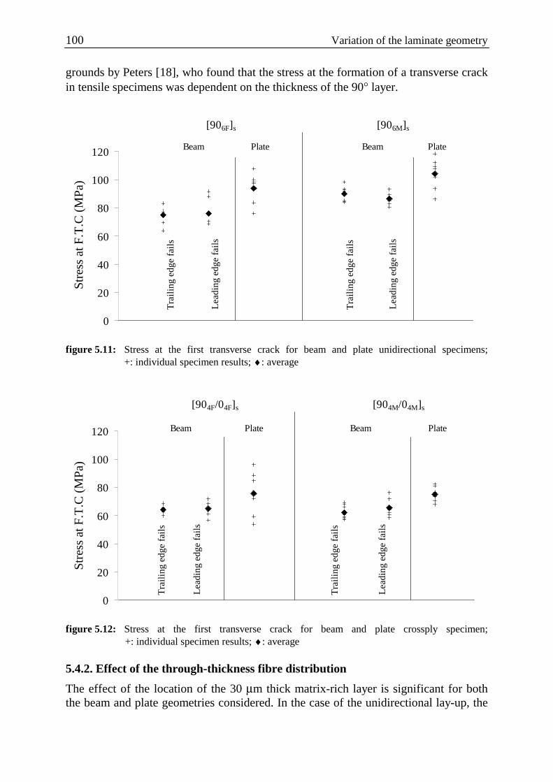
100 Variation of the laminate geometry
grounds by Peters [18], who found that the stress at the formation of a transverse crack in tensile specimens was dependent on the thickness of the 90° layer.
0
20
40
60
80
100
120
Stre
ss a
t F.T
.C (
MPa
)
[906F]s [906M]s
Beam Plate Beam Plate
Tra
ilin
g ed
ge f
ails
Lea
ding
edg
e fa
ils
Tra
ilin
g ed
ge f
ails
Lea
ding
edg
e fa
ils
figure 5.11: Stress at the first transverse crack for beam and plate unidirectional specimens;
+: individual specimen results; ♦: average
0
20
40
60
80
100
120
Stre
ss a
t F.T
.C (
MPa
)
[904F/04F]s [904M/04M]s
Beam Plate Beam Plate
Tra
ilin
g ed
ge f
ails
Lea
ding
edg
e fa
ils
Tra
ilin
g ed
ge f
ails
Lea
ding
edg
e fa
ils
figure 5.12: Stress at the first transverse crack for beam and plate crossply specimen;
+: individual specimen results; ♦: average
5.4.2. Effect of the through-thickness fibre distribution
The effect of the location of the 30 µm thick matrix-rich layer is significant for both the beam and plate geometries considered. In the case of the unidirectional lay-up, the

Chapter 5 101
shaded bars in figure 5.13 show that the stress at failure is always greater when the matrix rich zone is located outwards for an equivalent geometry. This increase in strength is also associated with unstable crack growth. In contrast, the stress at failure for cross-ply specimens (unshaded bars in figure 5.13) is essentially the same for a particular geometry, regardless of the through-thickness fibre distribution. The stresses at failure in cross-ply specimens are also lower than those for the corresponding unidirectional system. Hence in the case of the unidirectional material, having the matrix-rich layer oriented outwards serves as a protective layer, increasing the stress at the formation of the first transverse crack and preventing the formation of starter cracks from a free-surface defect.
40
50
60
70
80
90
100
110
120
Stre
ss a
t F.T
.C (
MPa
)
Unidirectional Cross-ply
Fibre rich zone outwards (F) Matrix rich zone outwards (M)
Beam Plate Beam Plate
Tra
ilin
g ed
ge
fail
s
Lea
ding
edg
e fa
ils T
rail
ing
edge
fa
ils
Lea
ding
edg
e fa
ils
figure 5.13: Comparison of the average stress at first transverse crack between unidirectional and
cross-ply beams and plates for the different configurations tested
Since the failure stress varies with fibre distribution in the unidirectional case, a direct consequence is that a single stress criterion, based on the stress at the formation of the first transverse crack of the unidirectional laminate, cannot be used as a fracture criterion. A possible explanation for the lower failure stress in the cross-ply specimen has been given in [13 (chapter 2 of this thesis)], based on the idea that interlaminar residual stresses in cross-ply laminates induce micro-damage on a fibre-matrix level. This finding has been supported by numerical results of a finite element model, focused on the stress arising around the fibre-matrix interface in the presence of interlaminar residual stresses in the cross-ply laminates. A study of a SEM image of a fracture surface gave the information that the fibre-matrix interface is generally poor in the case of the thermoplastic matrix used. The finite-element model therefore considered the non-adhesion of the matrix to the fibre as a first approximation. The model predicted a

102 Variation of the laminate geometry
maximum von Mises stress in the matrix with application of the residual stress alone of 122 MPa, which is higher than the matrix yield stress of around 105 MPa. This confirms the possibility of yielding around the fibre as was observed on the SEM micrography [13 (chapter 2 of this thesis)], when only the residual stresses are present after fabrication and before any mechanical loading of the cross-ply laminate. Although polyetherimide is known as being ductile, it is also notch sensitive and fails in a brittle manner when notches or other stress concentrations are present [19]. It is assumed that the plastic zone generated by the residual stresses provides a source of local crazes, which leads to early crack initiation. Any micro-damaged zone present in the 90° layer could also extend during subsequent loading, before coalescing to form a full crack. Such a micro-damage growth mechanism can also explain why having the matrix-rich region on the free-surface does not act as a protective layer in the cross-ply laminate. The micro-damage induced by the residual stress can propagate into the matrix layer, hence providing starter cracks at the free-surface. This would reduce the energy necessary to form the transverse crack and lead to a lower failure stress.

Chapter 5 103
5.5. Conclusion In this paper the influence of interlaminar residual stresses on the transverse cracking of transversally loaded carbon-polyetherimide cross-ply laminates has been considered. In particular the effects of the specimen edges on the cracking behaviour have been studied. For this purpose two different specimen geometries were used, a beam loaded under three-point bending and a square plate on a circular support loaded centrally by a spherical indenter. In addition, the effect of through thickness fibre distribution of the laminate was assessed. The validity of a single stress criterion to predict failure was checked by first testing unidirectional specimens, which have no interlaminar residual stresses and then with cross-ply laminates under the same test conditions. The following conclusions were drawn from the analysis of the stress normal to the transverse crack plane at the formation of the first transverse crack.
The stress reached at the formation of the first crack is lower in beams than in plate specimens. The presence of beam edges therefore has a negative influence on the strength of the structure, although the quality of the cut edges does not seem to effect the failure stress of the beams. There is a large variation in the stress at first transverse crack in the unidirectional specimens, depending on the specimen geometry, laminate lay-up and the presence of a matrix-rich zone at the specimen free surface. This means that this stress cannot be regarded as the intrinsic strength of the material in the transverse direction. It is interesting to note that the matrix-rich zone considered in this paper acts as a protection layer in the unidirectional laminates, which increases resistance to crack initiation but makes the subsequent crack growth unstable. Furthermore, the stress for first transverse crack formation in the cross-ply laminates is lower than the corresponding stress in the unidirectional laminate for every case considered. This makes the use of a single stress criterion invalid for the system considered. This reduction in stress for failure in cross-ply laminates can be due to micro-damage on a fibre-matrix scale which may provoke early crack growth. This micro-damage is induced by the presence of interlaminar residual stresses in the cross-ply laminates.

104 Variation of the laminate geometry
References 1. Liu, S., Nairn, J.A.; “The formation and propagation of matrix microcracks in cross-ply
laminates during static loading”; J. of Reinforced Plastics and Composites, Vol.11 (1992), p. 158-178.
2. Curson, A.D., Leach, D.C., Moore, D.R.; “Impact failure mechanisms of fiber thermoplastic composite”; Plastics, Rubber & Composites Processing & Applications; Vol. 17 (1992), p. 133-139.
3. Lammerant, L., Verpoest, I.; The interaction between matrix cracks and delaminations during quasi-static impact of composites; Composites Science & Technology, Vol. 51 (1994), p.505-516.
4. Highsmith, A.L., Reifsnider, K.L.; “Stiffness-reduction mechanisms in composite laminates”; Damage in Composite Materials, ASTM STP 775, Reifsnider, K. L., Ed, 1982, pp. 103-117.
5. Laws, N., Dvorak, G.J.; “Progressive transverse cracking in composite laminates”; J. of Composite Materials, Vol. 22 (1988), p. 900-916.
6. Kriz, R.D., Stinchcomb, W.W.; “Effects of moisture, residual thermal curing stresses, and mechanical load on the damage development in quasi-isotropic laminates”; Damage in Composite Materials, ASTM STP 775, K.L. Reifsnider, Ed., (1982), p. 63-80.
7. Liu, S., Kutlu, Z., Chang, F-K.; Matrix cracking and delamination in laminated composite beams subjected to a transverse concentrated line load; J. of Composite Materials, Vol. 27 (1993), p. 436.
8. Warnet, L., Reed, P.E., Akkerman, R.; “The effect of thermal residual stresses on transverse cracking in cross-ply Polyetherimide-carbon laminates under bending: variation of the laminate lay-up”; Prepared for publication.
9. Warnet, L., Reed, P.E., Akkerman, R.; “The effect of thermal residual stresses on transverse cracking in cross-ply Polyetherimide-carbon laminates under bending: variation of the testing temperature”; Prepared for publication.
10. Morris, W.L, Inman, R.V, Cox, B.N.; “Microscopic deformation in a heated unidirectional graphite-epoxy composite”; J. of Materials Science, Vol.24 (1989), p. 199-204.
11. Pipes, R.B., Pagano, N.J.; “Interlaminar stresses in composite laminates under uniform axial extension”; J. of Composite Materials, Vol. 4 (1970), p. 538-548.
12. Herakovitch, C.T.; “On the relationship between engineering properties and delamination of composite materials”; J. of Composite Materials, Vol. 15 (1981), 336-348.
13. Warnet, L., Reed, P.E., Akkerman, R.; “On the relaxation of thermal residual stresses and related damage in Carbon-Polyetherimide laminates”; Prepared for publication.
14. Gere, J.M., Timoshenko, S.P.; “Mechanics of materials”, Chapman & Hall (1991) 15. Eijpe, M.P.I.M.; “A modified layer removal method for determination of residual stresses in
Polymeric composites”; PhD Thesis, University of Twente (NL), ISBN 9036510155. 16. Guild, F.J., Ogin, S.L., Smith, P.A.; “Modelling of 90o ply cracking in crossply laminates,
including three-dimensional effects”; J. of Composite Materials, Vol. 27 (1993), p. 646-667. 17. Powell, P.C.; “Engineering with fibre-polymer laminates”; 1994, Chapman & Hall, London,
ISBN 0-412-49620-8 18. Peters, P.W.M.; “The strength distribution of 90o plies in 0/90/0 graphite-epoxy laminates”, J.
of Composites Materials, Vol. 18 (1984), p. 545-556. 19. Woods, J.T., Nimmer, R.P., Ryan, K.F.; “The development and validation of rate dependent
brittle failure criterion for polycarbonate and polyetherimide”; Antec’95, p. 3923-3930.

Chapter 6 105
Chapter 6
Concluding remarks
6.1. On the residual stress relaxation
Chapter 2 considered the evaluation of the relaxation of the ply-to-ply residual stress in carbon-polyetherimide cross-ply laminates from fabrication to testing. It is shown that, for this system, relaxation should be taken into account in any stress analysis where reasonable accuracy is required, for example when evaluating a failure criterion. A theoretical model based on viscoelastic behaviour of the polyetherimide matrix was used to evaluate the relaxation. Experiments conducted to measure the relaxation showed that the model requires some additional factors to be taken into consideration. The stress level reached in the carbon-polyetherimide system selected can induce transverse cracking, which contributes to the increase in compliance measured during relaxation. According to chapter 2 the contribution of both viscoelastic and damage mechanisms on the relaxation were of the same order of magnitude in the system considered. The experimental procedure used to measure the relaxation involved a low frequency loading-unloading cycle. The effect of using this technique on the actual relaxation of stress is unknown, but is thought to be small, as previously discussed in chapter 2.
6.2. On the presence of residual stress induced micro-damage
Although micro-damage induced by the thermal stresses was not observed as such, its existence was demonstrated in several indirect ways. Direct observation of micro-damage at the fibre-matrix interface would be extremely difficult with current knowledge and techniques. Any invasive techniques used to observe the damage at a microscopic could, themselves, be argued to have caused the damage. In chapter 3, arguments in support of micro-damage occurring were that the ratio between the theoretical and the experimental bending compliance before the occurrence of the first transverse crack decreased with increasing residual stress. It was argued that this relative increase in measured compliance can be related to the presence of residual stress induced micro-damage, which increases the compliance of each layer in a direction perpendicular to the fibres. This was interpreted by the use of an apparent transverse modulus E2d derived from the bending measurement. The observations based on the analysis of the experiments were supported by the numerical results of a FEM model, which evaluated the stresses in the matrix around the fibres in a cross-ply laminate, under the action of the residual stress alone. The model showed that the stresses reached in the matrix could exceed the yield stress of the polyetherimide, especially when the fibre-matrix bond was poor. It is argued that this can lead to local micro-cracking.

106 Conclusion
Chapter 5 shows that, for the same laminate lay-up, the stress at the formation of the first transverse crack is higher for the plate-like specimens than for the beam specimens. An increase of up to 25 % can be reached. It is worth noting that this edge effect is not influenced by the way the beam specimen edges are prepared. It was also shown that a matrix rich layer on the free surface enhances the strength of unidirectional specimens. This enhancement disappears in cross-ply specimens, due to the presence of residual stress. It is argued that the residual stress induced micro-damage can affect the matrix layer and therefore reduces the energy necessary to form a crack. Consideration of a maximum stress criterion to predict failure demonstrated that the presence of residual stress beyond a certain level could induce micro-damage. The conclusions which can be drawn on this basis are given in the next section.
6.3. On the use of strength-based failure criteria
The use of a maximum stress criterion to predict failure was used to highlight the presence of residual stress induced micro-damage. It shows that, for the geometry and the system chosen, the maximum stress criterion cannot be used for the system examined when the residual stress exceeds a critical value (25 MPa for the carbon-polyetherimide system considered). Beyond this critical value, micro-damage occurs under the action of residual stress. The application of a maximum stress criterion for the prediction of the formation of a transverse crack is known to be affected by the thickness of the 90° layer. The present study has shown that taking the residual stress for the evaluation of the stress criterion into account cannot simply be done by adding the residual stress to the mechanically applied stress. Chapter 3 shows that the residual stress relaxation plays an important role. It is also shown that, beyond a certain level of residual stress (25 MPa for the carbon-polyetherimide system considered), micro-damage occurs which leads to crack-like defects. These reduce the energy necessary to form a crack and therefore lowers the stress at failure. The fact that a matrix rich layer at the free surface of a laminate only enhances the failure stress in unidirectional structures also serves to show that a strength-based criterion is not applicable when residual stresses are present in the cross-ply structure.
6.4. On the use of fracture mechanics
The application of fracture mechanics requires the existence of an initial crack in the specimen. It has been argued that the residual stresses can lead to the formation of micro-cracks in the cross-ply beams, which makes the application of fracture mechanics approach promising. It was possible to describe, at least qualitatively, the dependence of the residual stress on the energy released at the formation of the first transverse crack. The limitation for producing a reliable prediction comes from the problems in the evaluation of an initial

Chapter 6 107
starter crack length, as well as the absence of critical energy release rate data on this material system, especially for the growth of a transverse crack. It is worth mentioning that the results presented in this study can provide a value for the critical energy release rate for transverse cracks as a first approximation. Values of 650 and 800 J/m2 are calculated, depending on the assumptions taken for calculating the residual stress.

108 Appendix

Appendix 109
Appendix A
E2 as a function of the curvature of a [90/0] laminate In the case of large plates, the classical lamination theory (i.e. using a linear strain-displacement relation) can be used to predict the curvature of non-symmetric plates [17,18]. We will here develop the CLT solution using the theorem of minimization of total potential energy. From this solution, an expression for the elasticity modulus of the off-axis layer will be derived. The total potential energy for a ply with thermal effects can be written as:
∫ −
∆−=
volextklijklijijkl WdVolTeeec
2
1W β
where ijβ are constants related to the thermomechanical properties of the layer. The
assumptions taken are: • During the cooling process: external work Wext is negligible. • Plane stress means that the tensor components ijklc reduces to the *ijQ with i,j =
1,2,6, and in the case of a 0° layer:
120
662112
121021
012
2112
2022
2112
1011 GQ
1
EQQ
1
EQ
1
EQ =
−==
−=
−= )(
*)(*
)(*
)(*
)(* ;;;
ννν
νννν
For the 90° layer, the reduced stiffness coefficient are transformed into the global coordinate system and become:
1290
662112
1219021
9012
2112
19022
2112
29011 GQ
1
EQQ
1
EQ
1
EQ =
−==
−=
−= )(
*)(
*)(
*)(
*)(
* ;;;νν
ννννν
• linear strain displacement relation:
0e
zy
wze
zx
wze
12
yoy2
2oyy22
xox2
2oxx11
=
+=−==
+=−==
κεδδεε
κεδδεε
• out of plane displacement field: 2
y2
x22
21 yxbyaxw κκ +=+=
These assumptions lead to 4 unknowns: oy
oxyx εεκκ ,,, which will be replaced in the
following expressions by a, b, c, d. The total potential energy then becomes:
[
]dxdydzTeQQ
TeQQ
eQeeQeQW
22k
2k
22k
1k
12
11k
2k
12k
1k
11
222
k222
12211
k12
n
1k xyz
211
k112
1
∆+−
∆+−
++= ∑∫∫∫=
)(
)()(
*)(*
)(*
)(*
)(*
)(*
)(*
)(*
)(*
)(*
)(*
αα
αα
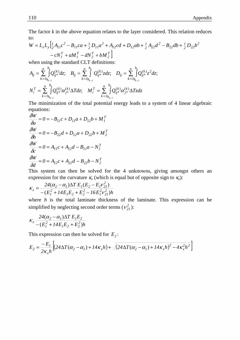
110 Appendix
The factor k in the above equation relates to the layer considered. This relation reduces to:
[]T
2T2
T1
T1
2222
122
2222
11212
2112
111
2112
1yx
MbdNaMcN
bDdbBdAabDcdAaDcaBcALLW
+−+−
+−++++−=
when using the standard CLT definitions:
∑ ∫ ∑ ∫∑ ∫= == − −−
===n
1k
h
h
n
1k
h
h
2kijij
kijij
n
1k
h
h
kijij
k
1k
k
1k
k
1k
dzzQDzdzQBdzQA ;;; )(*
)(*
)(*
∑ ∫∑ ∫== −−
∆=∆=n
1k
h
h
kj
kij
Ti
n
1k
h
h
kj
kij
Ti
k
1k
k
1k
TzdzQMTdzQN )(*
)(*
)(*
)(* ; αα
The minimization of the total potential energy leads to a system of 4 linear algebraic equations:
T2222212
T1111211
T2221222
T1121111
NbBdAcA0d
W
NaBdAcA0c
W
MbDaDdB0b
W
MbDaDcB0a
W
−−+==
−−+==
+++−==
+++−==
δδδ
δδδδδ
This system can then be solved for the 4 unknowns, giving amongst others an expression for the curvature κx (which is equal but of opposite sign to κy):
hE16EEE14E
EEET24221
21
2221
21
22112112
x)(
)()(
νναακ
−++−−∆−=
where h is the total laminate thickness of the laminate. This expression can be
simplified by neglecting second order terms ( 221ν ):
hEEE14E
EET242221
21
2112x
)(
)(
++−∆−αακ
This expression can then be solved for 2E :
( ) ( )[ ]22x
2x12x12
x
12 h4h14T24h14T24
h2
EE κκαακαα
κ−+−∆++−∆−= )()(

Appendix 111
Appendix B
Shear deflection of composite beams The unit-load method used by Gere & Timoshenko [1] for isotropic beams will be applied here for composite beams. This method is based on the principle of virtual work, which is stated by Timoshenko as follows: “If a deformable structure in equilibrium under the action of a system of loads is given a small virtual deformation, then the virtual work done by the external forces is equal to the virtual work done by the internal stress resultants.” In the unit-load method, the external virtual work extW
is the product of a unit load acting on the structure and the real displacement ∆ through which it moves. The internal virtual work intW is the work performed by the stress
resultants caused by the unit-load as those stresses move through the deformations caused by the actual loads:
int.1 W=∆ (B-1) The problem therefore implies the development of an expression for the internal virtual work. Only the axial and shear stress resultants will be considered here. For the isotropic case, these stresses are calculated as follows:
bI
QV
I
zM
y
yu
y
u == τσ ;
with Mu and Vu the bending moment and shear force caused by the unit load, Iy the second moment of inertia, z the vertical distance from the neutral axis to the point at which the stress is considered, Qy the first moment of the area under z and b the
specimen width. Using the notations defined in figure A.1, the bending stress )90(*1,bσ
and through the thickness shear stress )90(*1,bτ in the 90° layer are in the case of a [90/0]s
laminated beam:
)4
(2
; 22
90290)90(
*1,21)90(
*1, ztb
QwithbD
EQV
D
EzM ub
ub −=== τσ
with D the flexural flexibility, which in the case of the cross-ply laminated beams is
01902 IEIE + , and t the total beam thickness. The stresses in the core layer are:
)()()(with
(; ))(
*,)(*,
222
1222
210290
10290u01b
2u01b
z4
t
2
bE
4
t
4
t
2
bEEQEQ
bD
EQEQV
D
EzM
−+−=+
+==
γγ
τσ

112 Appendix
x(1*)
z(3) z(3)
y(2*)
b
L/2
900
0
tt
t
+=γ
t0
t90/2
figure A.1: Dimensions of the [90/0]s laminated beam.
The axial and shear strains in the 90° and the 0° directions are derived from the stresses but using LM and LV produced by the actual loads:
))()((;
)(;
)(*,
)(*,
)(*,
)(*,
22
1
222
213
L01b
L01b
22
23
2L901b
L901b
z4
tE
4
t
4
tE
DG2
V
D
zM
z4
t
DG2
EV
D
zM
−+−==
−==
γγε
γε
An expression for the virtual internal work acting on a differential element is obtained:
))(())((
))(())((
)0(*1,
)0(*1,
)90(*1,
)90(*1,
)0(*1,
)0(*1,
)90(*1,
)90(*1,int
dxdydzdxdydz
dxdydzdxdydzdW
bbbb
bbbb
γτγτ
εσεσ
++
+=
This expression needs to be integrated throughout the volume of the beam. The axial and shear term will be separated here for clarity. The axial term. The axial term of the virtual internal work is developed as follows:
∫ ∫∫∫ ∫∫
+
=
L 0A
22
LU0
L 90A
22
LU90axial dxdAz
D
MMEdxdAz
D
MMEWint,
The shear term. The shear term of the virtual work may be written as:
∫ ∫∫
∫ ∫∫
−+−+
−=
L 0A
22
2
1
222
213
2LU
L 90A
222
232
22LU
shear
dxdydzz4
tE
4
t
4
tE
GD4
VV
dxdydzz4
t
GD4
EVVW
)()(
)(int,
γ
which can be developed to:

Appendix 113
( )
−++
+−+
−+−=
532152
15
322
13
53
23
22
2
5
int,
6152241
4012815
1
8
γγγγγγ
γγγ
EEEE
G
G
E
D
bLtVVW Lu
shear
Application on a simply supported beam. The unit-load method will now be applied to the point loaded simply supported beam case. For a beam of length L, the following expressions for the unit-load and actual-load bending moment and shear force are valid:
2
FV
2
1V
2
FxM
2
xM LuLu ==== ;;;
For the axial term, expression B.1 simplifies to:
D48
FL3
axial =∆
Which is similar to the solution obtained by Timoshenko [1]. For the shear term, we obtain:
( )
−++
+−+
−+−=∆
532152
15
322
13
53
23
22
2
5
6152241
4012815
1
32
γγγγγγ
γγγ
EEEE
G
G
E
D
FbLtshear
Adding the last two expressions gives the total deflection. It is given here as a compliance csth:
( )
−++
+−+
−+−
++
+=
532152
15
322
13
53
23
22
290201
5
90201
3
6152241
40128151
)(32)(48
γγγγγγ
γγγ
EEEE
G
G
E
IEIE
bLh
IEIE
Lcsth
It is worth noting that this last expression simplifies for a unidirectional laminate or even an isotropic beam ( 0;; 0231321 === tGGEE ) to the Gere & Timoshenko
relation obtained following the same principle:
GA
L
EI
Lcsth 10
3
48
3+=
Reference: 1. Gere, J.M., Timoshenko, S.P.; “Mechanics of materials”, Chapman & Hall (1991)
ba =


Nawoord Merci: De dames, heren, leuke lui, gezellige ploeg studenten uit de Universiteit Twente die op wat voor manier dan ook een bijdrage hebben geleverd aan dit werk. Ten Cate Advanced Composites, want zonder materiaal was ik niet ver gegaan. Monsieur Peter, voor je geduld, pit, humor, inspiratie en je vriendschap. Familie en vrienden die mij gesteund hebben, ook al ging het niet altijd van een leien dakje. Truitje voor de dagelijkse haptonomie. En Puck voor je lachjes!


