Embed Size (px)
Citation preview
A Framework for the Automatic Geometric Re-pair of CityGML Models
Junqiao Zhao* **, Jantien Stoter*, Hugo Ledoux*
* Department of GIS Technology, Delft University of Technology, Delft, the Netherlands ** College of Surveying and Geo-Information, Tongji University, Shanghai, P.R. China Abstract. Three-dimensional (3D) city models based on the OGC CityGML standard have become increasingly available in the past few years. Although GIS applications call for standardized and geometric-topological rigorous 3D models, many existing visually satisfied 3D city datasets show weak or invalid geometry. These defects prohibit the downstream applications of such models. As a result, intensive manual work of model repair has to be conducted which is complex and labour-intensive. Although model repair is already a popular research topic for CAD models and is becoming im-portant in GIS, existing researches either focus on certain defects or on a particular geometric primitive. Therefore a framework that explores the full set of validation requirements and provides ways to repair a CityGML mod-el according to these requirements is needed and proposed in this paper. First, the validity criteria of CityGML geometric model is defined, which guarantees both the rigorous geometry for analytical use and the flexible representation of geographic features. Then, a recursive repair framework aiming at obtaining a valid CityGML model is presented. The geometric terms adopted in this paper are compliant with the ISO19107 standard. Fu-ture work will further implement the framework.
Keywords: 3D models, CityGML, Validity, Repair
1. Introduction Three-dimensional (3D) Geo-information has been treated as one of the essential sources of the latest and future GIS applications (Gruen 2008, Gröger et al. 2012, Stoter et al. 2013). However, current practice of digital city modeling focuses mainly on the visual appearance of the model rather than on the correctness of geometric-topological structure (Gröger & Plümer 2009). As a result, most of the analytical applications cannot be conducted with these ill-posed models, such as geometric processing, struc-
tural and environmental analysis and indoor navigation (Hughes et al. 2005, Isikdag et al. 2008, Haala et al. 2011). This is seen as a significant bottle-neck of the 3D GIS industry and a waste of the expensive modeling efforts and expenses.
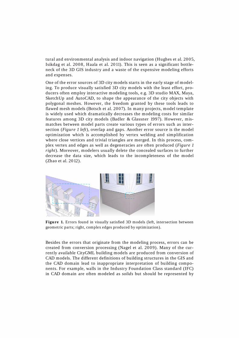
One of the error sources of 3D city models starts in the early stage of model-ing. To produce visually satisfied 3D city models with the least effort, pro-ducers often employ interactive modeling tools, e.g. 3D studio MAX, Maya, SketchUp and AutoCAD, to shape the appearance of the city objects with polygonal meshes. However, the freedom granted by these tools leads to flawed mesh models (Botsch et al. 2007). In many projects, model template is widely used which dramatically decreases the modeling costs for similar features among 3D city models (Badler & Glassner 1997). However, mis-matches between model parts create various types of errors such as inter-section (Figure 1 left), overlap and gaps. Another error source is the model optimization which is accomplished by vertex welding and simplification where close vertices and trivial triangles are merged. In this process, com-plex vertex and edges as well as degeneracies are often produced (Figure 1 right). Moreover, modelers usually delete the concealed surfaces to further decrease the data size, which leads to the incompleteness of the model (Zhao et al. 2012).
Figure 1. Errors found in visually satisfied 3D models (left, intersection between geometric parts; right, complex edges produced by optimization).
Besides the errors that originate from the modeling process, errors can be created from conversion processing (Nagel et al. 2009). Many of the cur-rently available CityGML building models are produced from conversion of CAD models. The different definitions of building structures in the GIS and the CAD domain lead to inappropriate interpretation of building compo-nents. For example, walls in the Industry Foundation Class standard (IFC) in CAD domain are often modeled as solids but should be represented by
surfaces in CityGML (Liebich et al. 2010, Gröger et al. 2012). For the sake of simplicity, the solid wall is converted into a set of MultiSurfaces, which omits not only the volume information of the component itself but also the topological relationships between walls. Additionally, errors may occur in the semantics editing process of CityGML models, if mistakes are made when manually matching geometries with CityGML semantics (Benner et al. 2005, Wagner et al. 2012).
Repair of 3D geometric models has become an important topic in the field of CAD and computer graphics. A number of repair methods have been proposed for polygonal meshes (Ju 2009, Campen et al. 2012). These ap-proaches are however not sufficient for city models, since 3D city models are usually aggregated models, made up by heterogeneous geometric primi-tives in multiple dimensions. In the field of GIS, previous researches stud-ied the validation of geometric models. Van Oosterom et al. (2004) pro-posed an extended definition and a set of validation rules for polygons. Ka-zar et al. (2008) introduced the validation rules for geometry defined in Oracle, especially the surface and solid, but no repair method is provided. Verbree & Si (2008) and Ledoux et al. (2009) proposed methods to validate the GML solids based on tetrahedralizations. Gröger & Plümer (2012a, b) proposed rules and axioms for consistent representation and updating of 3D city models. However, their definition of geometry is not fully con-formed to the ISO19107 standard, which is the geometric base for CityGML (Gröger et al. 2012).
Recently, repair pipeline for CityGML models have been proposed in (Bog-dahn & Coors 2010, Wagner et al. 2012). Although both the geometric and semantic aspects are included, they only repair errors that are similar to mesh repair, such as holes and incorrect orientations of mesh surface, while the overview of the different types of geometric errors of CityGML model concerning the downstream applications and their repair is not provided.
Starting with the definition of valid and invalid geometric model for CityGML models in Section 2, a framework for repair of geometric errors of CityGML is proposed in Section 3, which is a recursive framework and deals with the hierarchies of the CityGML model. Finally, we conclude with a dis-cussion on the implementation issues and on future realizations.
2. Validity of CityGML Models Before repairing, we should first agree on an exact definition of valid and invalid 3D city models. The ISO19107 standard provides the criteria of valid geometry, such as simple and orientable (Herring 2005). The question is whether these criteria are sufficient for the downstream applications.
In visualization applications, such as urban planning and virtual reality, only the geometric primitives, i.e. point, curve and surface are required, thus no strict requirements is needed for the input geometry (Hearn & Baker 1996). In more sophisticated GIS applications, accurate and faithful representation of geographic features and their embedding in the space are mandatory, such as 3D cadastre, thus the n-D geometric object should rep-resents the continuous image of an n-D space (Herring 2005). This is de-fined as simple in the ISO19107 standard.
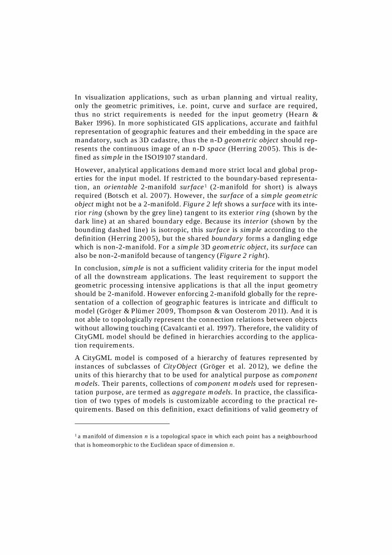
However, analytical applications demand more strict local and global prop-erties for the input model. If restricted to the boundary-based representa-tion, an orientable 2-manifold surface1 (2-manifold for short) is always required (Botsch et al. 2007). However, the surface of a simple geometric object might not be a 2-manifold. Figure 2 left shows a surface with its inte-rior ring (shown by the grey line) tangent to its exterior ring (shown by the dark line) at an shared boundary edge. Because its interior (shown by the bounding dashed line) is isotropic, this surface is simple according to the definition (Herring 2005), but the shared boundary forms a dangling edge which is non-2-manifold. For a simple 3D geometric object, its surface can also be non-2-manifold because of tangency (Figure 2 right).
In conclusion, simple is not a sufficient validity criteria for the input model of all the downstream applications. The least requirement to support the geometric processing intensive applications is that all the input geometry should be 2-manifold. However enforcing 2-manifold globally for the repre-sentation of a collection of geographic features is intricate and difficult to model (Gröger & Plümer 2009, Thompson & van Oosterom 2011). And it is not able to topologically represent the connection relations between objects without allowing touching (Cavalcanti et al. 1997). Therefore, the validity of CityGML model should be defined in hierarchies according to the applica-tion requirements.
A CityGML model is composed of a hierarchy of features represented by instances of subclasses of CityObject (Gröger et al. 2012), we define the units of this hierarchy that to be used for analytical purpose as component models. Their parents, collections of component models used for represen-tation purpose, are termed as aggregate models. In practice, the classifica-tion of two types of models is customizable according to the practical re-quirements. Based on this definition, exact definitions of valid geometry of
1 a manifold of dimension n is a topological space in which each point has a neighbourhood that is homeomorphic to the Euclidean space of dimension n.
component model as well as of aggregate model are proposed in the next section.
Figure 2. Non-2-manifold simple geometric objects (left: a simple surface with its interior ring tangent to its exterior ring; right: a simple composite solid)
2.1. Valid geometry of component models Based on the previous definition, the component model is the unit for geo-metric processing applications, thus 2-manifold should be the criteria for the valid geometry. If a component model is represented by only the 0D and 1D geometric objects, i.e. point and line string, simple is the sufficient va-lidity criteria because points and line strings are the lower dimensional primitives of a 2-manifold. However, if 0D or 1D geometric primitives are presented in a higher dimensional (2D or 3D) component model, they should be eliminated because they form dangling cases which are non-2-manifold.
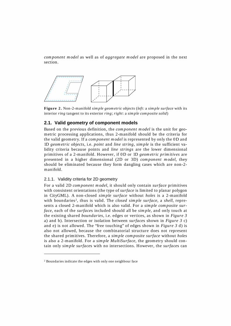
2.1.1. Validity criteria for 2D geometry For a valid 2D component model, it should only contain surface primitives with consistent orientations (the type of surface is limited to planar polygon in CityGML). A non-closed simple surface without holes is a 2-manifold with boundaries2, thus is valid. The closed simple surface, a shell, repre-sents a closed 2-manifold which is also valid. For a simple composite sur-face, each of the surfaces included should all be simple, and only touch at the existing shared boundaries, i.e. edges or vertices, as shown in Figure 3 a) and b). Intersection or isolation between surfaces shown in Figure 3 c) and e) is not allowed. The “free touching” of edges shown in Figure 3 d) is also not allowed, because the combinatorial structure does not represent the shared primitives. Therefore, a simple composite surface without holes is also a 2-manifold. For a simple MultiSurface, the geometry should con-tain only simple surfaces with no intersections. However, the surfaces can
2 Boundaries indicate the edges with only one neighbour face
be isolated from each other or touch at an existing shared boundary. Both are valid cases that form a 2-manifold3.
Figure 3. Valid and invalid cases of a composite surface (a) a valid composite surface which is also simple; b) an valid composite surface where the dashed line indicates two identical vertices; c) an invalid composite surface with one of its surface isolated; d) an invalid composite surface containing a “free touching” between two surfaces; e) an invalid composite surface with its surfaces intersected and form a complex edge)
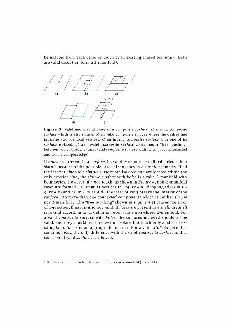
If holes are present in a surface, its validity should be defined stricter than simple because of the possible cases of tangency in a simple geometry. If all the interior rings of a simple surface are isolated and are located within the only exterior ring, the simple surface with holes is a valid 2-manifold with boundaries. However, if rings touch, as shown in Figure 4, non-2-manifold cases are formed, i.e. singular vertices In Figure 4 a), dangling edges in Fi-gure 4 b) and c). In Figure 4 d), the interior ring breaks the interior of the surface into more than one connected components which is neither simple nor 2-manifold. The “free touching” shown in Figure 4 e) causes the error of T-junction, thus it is also not valid. If holes are present in a shell, the shell is invalid according to its definition even it is a non-closed 2-manifold. For a valid composite surface with holes, the surfaces included should all be valid, and they should not intersect or isolate, but touch only at shared ex-isting boundaries in an appropriate manner. For a valid MultiSurface that contains holes, the only difference with the valid composite surface is that isolation of valid surfaces is allowed.
3 The disjoint union of a family of n-manifolds is a n-manifold (Lee 2010)
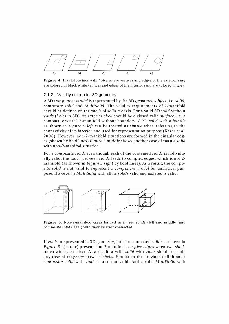
Figure 4. Invalid surface with holes where vertices and edges of the exterior ring are colored in black while vertices and edges of the interior ring are colored in grey
2.1.2. Validity criteria for 3D geometry A 3D component model is represented by the 3D geometric object, i.e. solid, composite solid and MultiSolid. The validity requirements of 2-manifold should be defined on the shells of solid models. For a valid 3D solid without voids (holes in 3D), its exterior shell should be a closed valid surface, i.e. a compact, oriented 2-manifold without boundary. A 3D solid with a handle as shown in Figure 5 left can be treated as simple when referring to the connectivity of its interior and used for representation purpose (Kazar et al. 2008). However, non-2-manifold situations are formed in the singular edg-es (shown by bold lines) Figure 5 middle shows another case of simple solid with non-2-manifod situation.
For a composite solid, even though each of the contained solids is individu-ally valid, the touch between solids leads to complex edges, which is not 2-manifold (as shown in Figure 5 right by bold lines). As a result, the compo-site solid is not valid to represent a component model for analytical pur-pose. However, a MultiSolid with all its solids valid and isolated is valid.
Figure 5. Non-2-manifold cases formed in simple solids (left and middle) and composite solid (right) with their interior connected
If voids are presented in 3D geometry, interior connected solids as shown in Figure 6 b) and c) present non-2-manifold complex edges when two shells touch with each other. As a result, a valid solid with voids should exclude any case of tangency between shells. Similar to the previous definition, a composite solid with voids is also not valid. And a valid MultiSolid with
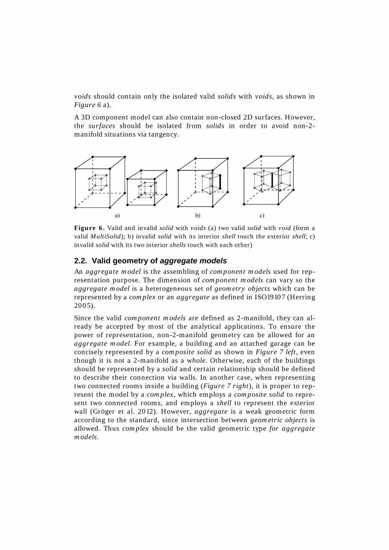
voids should contain only the isolated valid solids with voids, as shown in Figure 6 a).
A 3D component model can also contain non-closed 2D surfaces. However, the surfaces should be isolated from solids in order to avoid non-2-manifold situations via tangency.
Figure 6. Valid and invalid solid with voids (a) two valid solid with void (form a valid MultiSolid); b) invalid solid with its interior shell touch the exterior shell; c) invalid solid with its two interior shells touch with each other)
2.2. Valid geometry of aggregate models An aggregate model is the assembling of component models used for rep-resentation purpose. The dimension of component models can vary so the aggregate model is a heterogeneous set of geometry objects which can be represented by a complex or an aggregate as defined in ISO19107 (Herring 2005).
Since the valid component models are defined as 2-manifold, they can al-ready be accepted by most of the analytical applications. To ensure the power of representation, non-2-manifold geometry can be allowed for an aggregate model. For example, a building and an attached garage can be concisely represented by a composite solid as shown in Figure 7 left, even though it is not a 2-manifold as a whole. Otherwise, each of the buildings should be represented by a solid and certain relationship should be defined to describe their connection via walls. In another case, when representing two connected rooms inside a building (Figure 7 right), it is proper to rep-resent the model by a complex, which employs a composite solid to repre-sent two connected rooms, and employs a shell to represent the exterior wall (Gröger et al. 2012). However, aggregate is a weak geometric form according to the standard, since intersection between geometric objects is allowed. Thus complex should be the valid geometric type for aggregate models.
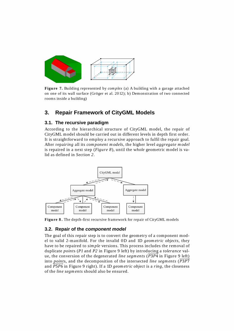
Figure 7. Building represented by complex (a) A building with a garage attached on one of its wall surface (Gröger et al. 2012); b) Demonstration of two connected rooms inside a building)
3. Repair Framework of CityGML Models
3.1. The recursive paradigm According to the hierarchical structure of CityGML model, the repair of CityGML model should be carried out in different levels in depth first order. It is straightforward to employ a recursive approach to fulfil the repair goal. After repairing all its component models, the higher level aggregate model is repaired in a next step (Figure 8), until the whole geometric model is va-lid as defined in Section 2.
Figure 8. The depth-first recursive framework for repair of CityGML models
3.2. Repair of the component model The goal of this repair step is to convert the geometry of a component mod-el to valid 2-manifold. For the invalid 0D and 1D geometric objects, they have to be repaired to simple versions. This process includes the removal of duplicate points (P1 and P2 in Figure 9 left) by introducing a tolerance val-ue, the conversion of the degenerated line segments (𝑃3𝑃4�����������⃑ in Figure 9 left) into points, and the decomposition of the intersected line segments (𝑃3𝑃7�����������⃑ and 𝑃5𝑃6�����������⃑ in Figure 9 right). If a 1D geometric object is a ring, the closeness of the line segments should also be ensured.
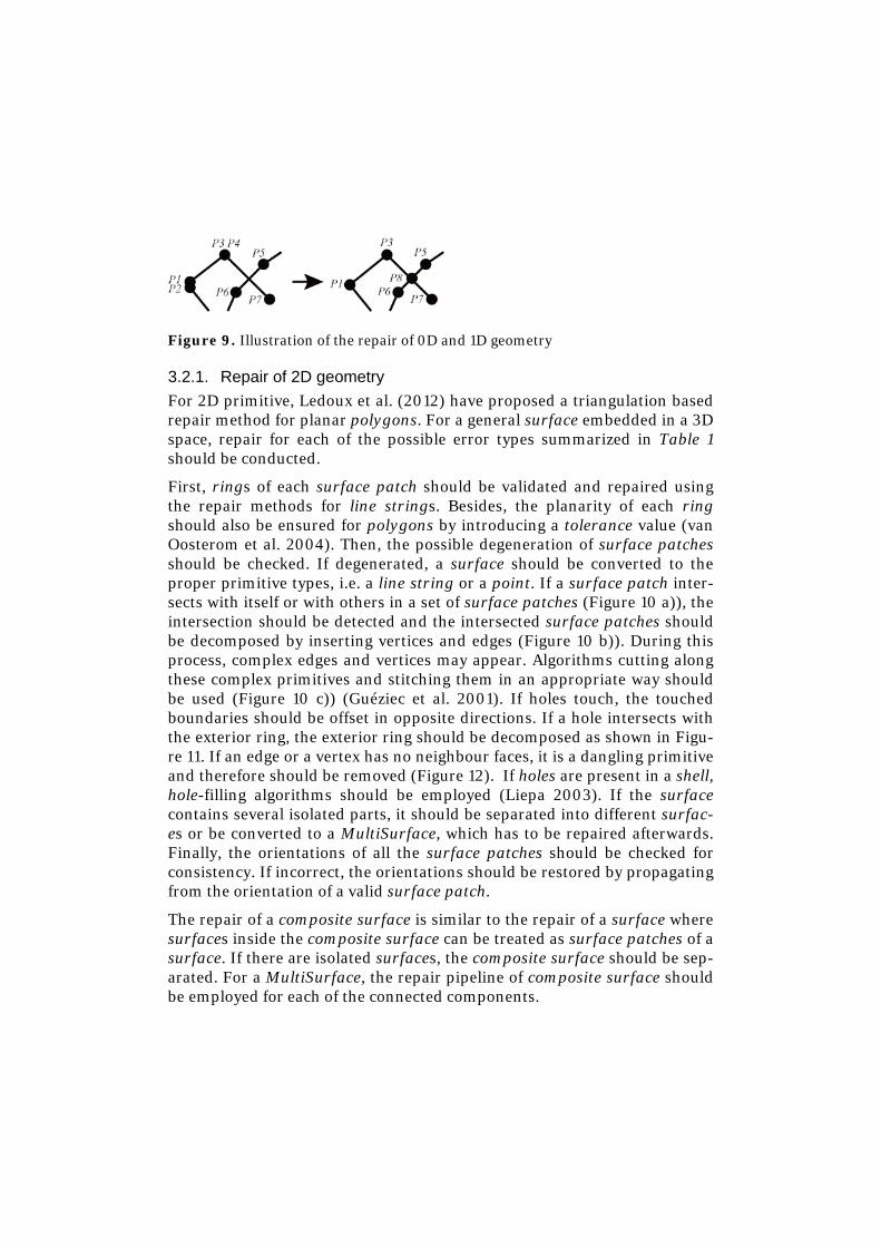
Figure 9. Illustration of the repair of 0D and 1D geometry
3.2.1. Repair of 2D geometry For 2D primitive, Ledoux et al. (2012) have proposed a triangulation based repair method for planar polygons. For a general surface embedded in a 3D space, repair for each of the possible error types summarized in Table 1 should be conducted.
First, rings of each surface patch should be validated and repaired using the repair methods for line strings. Besides, the planarity of each ring should also be ensured for polygons by introducing a tolerance value (van Oosterom et al. 2004). Then, the possible degeneration of surface patches should be checked. If degenerated, a surface should be converted to the proper primitive types, i.e. a line string or a point. If a surface patch inter-sects with itself or with others in a set of surface patches (Figure 10 a)), the intersection should be detected and the intersected surface patches should be decomposed by inserting vertices and edges (Figure 10 b)). During this process, complex edges and vertices may appear. Algorithms cutting along these complex primitives and stitching them in an appropriate way should be used (Figure 10 c)) (Guéziec et al. 2001). If holes touch, the touched boundaries should be offset in opposite directions. If a hole intersects with the exterior ring, the exterior ring should be decomposed as shown in Figu-re 11. If an edge or a vertex has no neighbour faces, it is a dangling primitive and therefore should be removed (Figure 12). If holes are present in a shell, hole-filling algorithms should be employed (Liepa 2003). If the surface contains several isolated parts, it should be separated into different surfac-es or be converted to a MultiSurface, which has to be repaired afterwards. Finally, the orientations of all the surface patches should be checked for consistency. If incorrect, the orientations should be restored by propagating from the orientation of a valid surface patch.
The repair of a composite surface is similar to the repair of a surface where surfaces inside the composite surface can be treated as surface patches of a surface. If there are isolated surfaces, the composite surface should be sep-arated. For a MultiSurface, the repair pipeline of composite surface should be employed for each of the connected components.
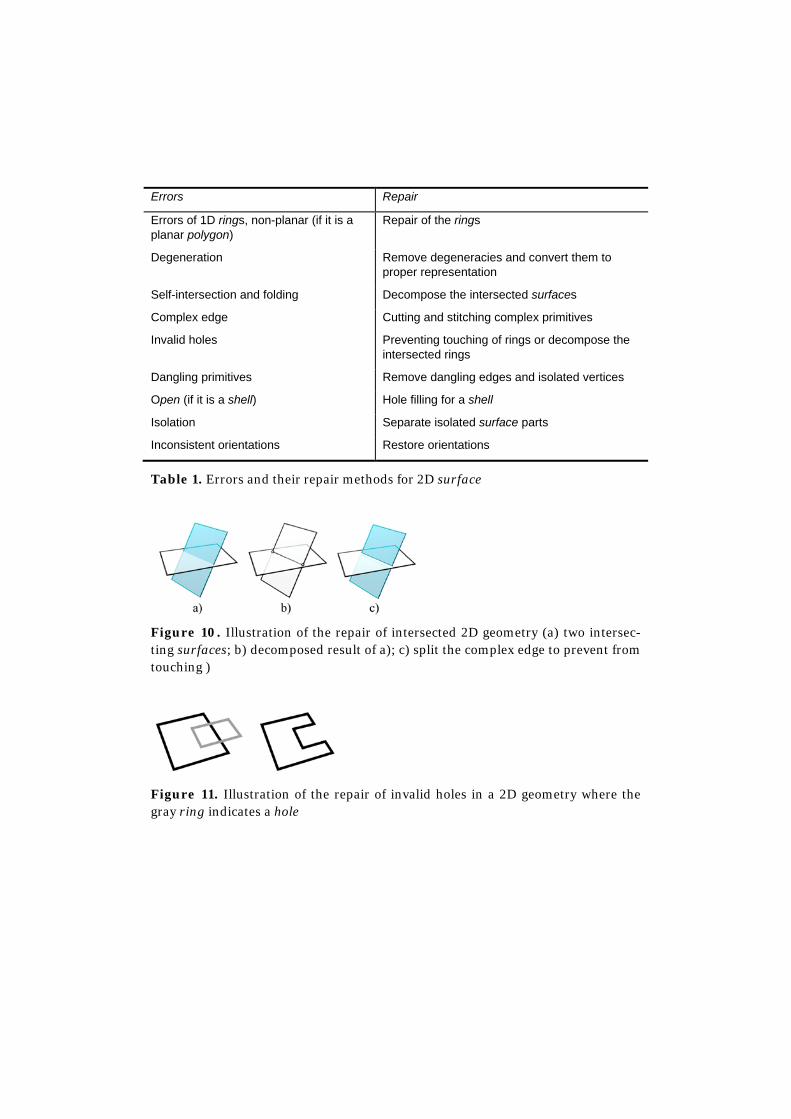
Errors Repair
Errors of 1D rings, non-planar (if it is a planar polygon)
Repair of the rings
Degeneration Remove degeneracies and convert them to proper representation
Self-intersection and folding Decompose the intersected surfaces
Complex edge Cutting and stitching complex primitives
Invalid holes Preventing touching of rings or decompose the intersected rings
Dangling primitives Remove dangling edges and isolated vertices
Open (if it is a shell) Hole filling for a shell
Isolation Separate isolated surface parts
Inconsistent orientations Restore orientations
Table 1. Errors and their repair methods for 2D surface
Figure 10. Illustration of the repair of intersected 2D geometry (a) two intersec-ting surfaces; b) decomposed result of a); c) split the complex edge to prevent from touching )
Figure 11. Illustration of the repair of invalid holes in a 2D geometry where the gray ring indicates a hole
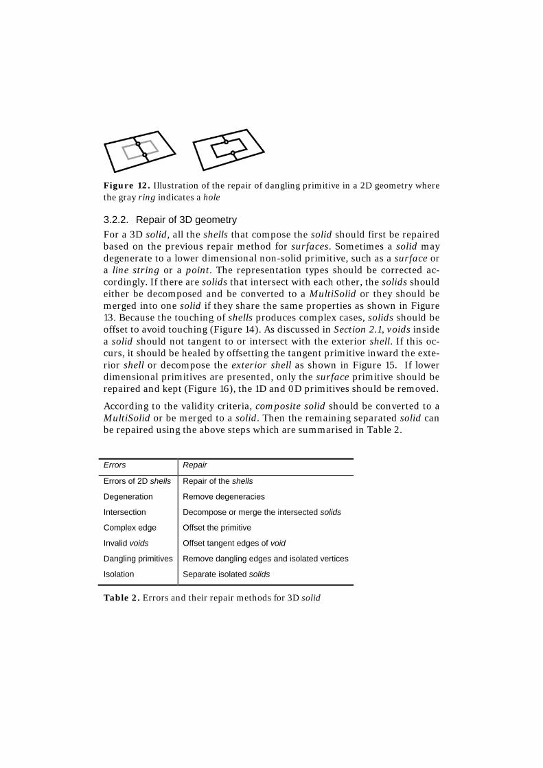
Figure 12. Illustration of the repair of dangling primitive in a 2D geometry where the gray ring indicates a hole
3.2.2. Repair of 3D geometry For a 3D solid, all the shells that compose the solid should first be repaired based on the previous repair method for surfaces. Sometimes a solid may degenerate to a lower dimensional non-solid primitive, such as a surface or a line string or a point. The representation types should be corrected ac-cordingly. If there are solids that intersect with each other, the solids should either be decomposed and be converted to a MultiSolid or they should be merged into one solid if they share the same properties as shown in Figure 13. Because the touching of shells produces complex cases, solids should be offset to avoid touching (Figure 14). As discussed in Section 2.1, voids inside a solid should not tangent to or intersect with the exterior shell. If this oc-curs, it should be healed by offsetting the tangent primitive inward the exte-rior shell or decompose the exterior shell as shown in Figure 15. If lower dimensional primitives are presented, only the surface primitive should be repaired and kept (Figure 16), the 1D and 0D primitives should be removed.
According to the validity criteria, composite solid should be converted to a MultiSolid or be merged to a solid. Then the remaining separated solid can be repaired using the above steps which are summarised in Table 2.
Errors Repair
Errors of 2D shells Repair of the shells
Degeneration Remove degeneracies
Intersection Decompose or merge the intersected solids
Complex edge Offset the primitive
Invalid voids Offset tangent edges of void
Dangling primitives Remove dangling edges and isolated vertices
Isolation Separate isolated solids
Table 2. Errors and their repair methods for 3D solid
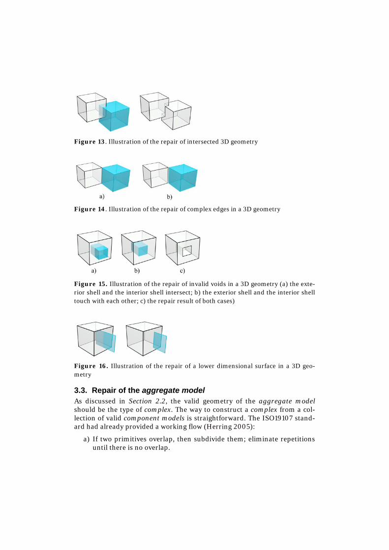
Figure 13. Illustration of the repair of intersected 3D geometry
Figure 14. Illustration of the repair of complex edges in a 3D geometry
Figure 15. Illustration of the repair of invalid voids in a 3D geometry (a) the exte-rior shell and the interior shell intersect; b) the exterior shell and the interior shell touch with each other; c) the repair result of both cases)
Figure 16. Illustration of the repair of a lower dimensional surface in a 3D geo-metry
3.3. Repair of the aggregate model As discussed in Section 2.2, the valid geometry of the aggregate model should be the type of complex. The way to construct a complex from a col-lection of valid component models is straightforward. The ISO19107 stand-ard had already provided a working flow (Herring 2005):
a) If two primitives overlap, then subdivide them; eliminate repetitions until there is no overlap.
b) Similarly, if a primitive is not simple, subdivide it where it intersects itself; eliminate repetitions until there is no overlap.
c) If a primitive is not a point, calculate its boundary as a collection of other primitives, using those already in the generating set if possible, and insert them into the complex.
d) Repeat step “a” through “c” until no new primitive is required.
During this repair process, the decomposition of the intersecting compo-nent models will not produce invalid geometry for the component models.
3.4. Implementation Issues In order to implement the framework, some crucial aspects should be con-sidered.
First, the data structure should be able to faithfully record the input model without missing important information. In the geometry aspect, generic boundary based representation based data structure should be adopted which supports all the geometric types defined in CityGML and is also able to represent invalid non-2-manifold edges and vertices. Tolerance values are important to define the condition of duplication and coplanar, and should therefore be defined carefully. Due to the uncertainty caused by pos-sible rounding-off error, exact predict method or even exact arithmetic should be used (Richard Shewchuk 1997). Then, basic repair routines should be developed, such as triangulation, which converts the input model into simplical 2-complex based representation; regularization, which re-moves dangling 0D or 1D elements (Granados et al. 2003, Worboys & Duckham 2004), and intersection and decomposition, which extract the intersected geometric primitives and decomposes the model based on the extracted intersection. More mesh repair methods like hole-filling, non-2-manifold curing should also be incorporated (Campen et al. 2012). Finally, the developed repair method should be modularized and conducted in an optimised order so that repair should not introduce unsolved errors.
4. Conclusion This paper provides a definition of valid geometric model for CityGML con-cerning both the rigorous geometry for analytical purpose and the flexibility for representation purpose. Possible errors for both the component models and aggregate models defined for CityGML models are summarized and their healing steps are introduced within a repair framework. The goal of the repair is to achieve a valid CityGML model that can be used for most
downstream applications other than only be used for visualization or repre-sentation.
Future work comprises the design and implementation of the data structure for the repair of the CityGML models. The automatic repair routines dis-cussed before should then be developed based on the proper data structure. This paper mainly focus on the geometric aspect of repair, thus the seman-tics of the CityGML model should be further exploited to strengthen the ability of repair on specified models, such as a building. Finally, this paper assumes the correctness of the semantic information, and excludes other repair issues listed in the ISO19157 standard (ISO 2012). These topics should be studied in the follow-up researches.
Acknowledgements This work is supported by the National Natural Science Foundation of Chi-na (41201379 and 41171311), the Dutch Technology Foundation STW, which is part of the Netherlands Organization for Scientific Research (NWO) and partly funded by the Ministry of Economic Affairs, Agriculture and Innova-tion. (Project code: 11300).
References Badler, NI and Glassner, AS (1997) 3D object modeling. SIGGRAPH 97 Introduc-
tion to Computer Graphics Course Notes
Benner, J, Geiger, A and Leinemann, K (2005) Flexible Generation of Semantic 3D Building Models, International ISPRS / EuroSDR / DGPF-Workshop on Next Generation 3D City Models. EuroSDR, Bonn, Germany
Bogdahn, J and Coors, V (2010) Towards an automated Healing of 3D urban mod-els. In: T. Kolbe, G. König and N. Claus (Eds), Proceedings of International Con-ference on 3D Geoinformation. Int. Archives of Photogrammetry, Remote Sens-ing and Spatial Information Science, Vol XXXVIII-4/W15. Aachen: Shaker Verlag GmbH, pp. 13-17
Botsch, M et al. (2007) Geometric Modeling based on Polygonal Meshes, ACM SIGGRAPH 2007 courses. ACM New York, NY, USA
Campen, M, Attene, M and Kobbelt, L (2012) A Practical Guide to Polygon Mesh Repairing. The Eurographics Association, pp. t4-undefined
Cavalcanti, PR, Carvalho, PCP and Martha, LF (1997) Non-manifold modelling: an approach based on spatial subdivision. Computer-Aided Design, 29(3): 209-220
Granados, M et al. (2003) Boolean operations on 3D selective Nef complexes: Data structure, algorithms, and implementation. In: G. Di Battista and U. Zwick (Eds),
Algorithms - ESA 2003: 11th Annual European Symposium. Lecture Notes in Computer Science. Springer, Budapest, Hugary, September 2003, pp. 174–186
Gröger, G and Plümer, L (2009) How to achieve consistency for 3D city models. GeoInformatica, 15:137-165
Gröger, G and Plümer, L (2012a) Provably correct and complete transaction rules for updating 3D city models. Geoinformatica: 1-34
Gröger, G and Plümer, L (2012b) Transaction rules for updating surfaces in 3D GIS. ISPRS Journal of Photogrammetry and Remote Sensing, 69: 134-145
Gröger, G, Kolbe, TH, Nagel, C and Häfele, K (2012) OpenGIS City Geography Markup Language (CityGML) Encoding Standard. Version 2.0.0. Open Geospa-tial Consortium. OGC 12-019
Gruen, A (2008) Reality-based generation of virtual environments for digital earth. International Journal of Digital Earth, 1(1): 88-106
Guéziec, A, Taubin, G, Lazarus, F and Hom, B (2001) Cutting and stitching: Con-verting sets of polygons to manifold surfaces. IEEE Transactions on Visualization and Computer Graphics, 7(2): 136-151
Haala, N, Fritsch, D, Peter, M and Khosravani, A (2011) Pedestrian Navigation and Modeling for Indoor Environments, Proceeding of 7th International Symposium on Mobile Mapping Technology, Cracow, Poland
Hearn, D and Baker, MP (1996) Computer Graphics, C version. Prentice Hall, 652 pp
Herring, JR (2005) ISO 19107:2005: Geographic information-Spatial schema. In-ternational Organization for Standardization
Hughes, T, Cottrell, JA and Bazilevs, Y (2005) Isogeometric analysis: CAD, finite elements, NURBS, exact geometry and mesh refinement. Computer Methods in Applied Mechanics and Engineering, 194(39-41): 4135-4195
Isikdag, U, Underwood, J and Aouad, G (2008) An investigation into the applica-bility of building information models in geospatial environment in support of site selection and fire response management processes. Advanced Engineering In-formatics, 22(4): 504-519
ISO (2012) ISO 19157: Geographic information - Data quality. International Organ-ization for Standardization
Ju, T (2009) Fixing geometric errors on polygonal models: a survey. Journal of Computer Science and Technology, 24(1): 19-29
Kazar, BM, Kothuri, R, Oosterom, P and Ravada, S (2008) On valid and invalid three-dimensional geometries, Advances in 3D Geoinformation Systems. Lecture Notes in Geoinformation and Cartography. Springer Berlin Heidelberg, pp. 19-46
Ledoux, H, Ohori, KA and Meijers, M (2012) Automatically repairing invalid poly-gons with a constrained triangulation, Proceedings of Agile 2012, Avignon, France
Ledoux, H, Verbree, E and Si, H (2009) Geometric Validation of GML Solids with
the Constrained Delaunay Tetrahedralization, Proceedings of the 4th Interna-tional Workshop on 3D Geo-Information, Ghent, Belgium
Lee, JM (2010) Introduction to topological manifolds. Graduate Texts in Mathe-matics, 202. Springer New York, 433 pp
Liebich, T et al. (2010) Industry Foundation Classes 2x4 (IFC2x4) Release Candi-date 2
Liepa, P (2003) Filling holes in meshes. Eurographics Association, pp. 200-205
Nagel, C, Stadler, A and Kolbe, TH (2009) Conceptual requirements for the auto-matic reconstruction of building information models from uninterpreted 3D models. In: T.H. Kolbe, H. Zhang and S. Zlatanova (Eds), GeoWeb 2009 Academ-ic Track - Cityscapes, Vancouver, BC, Canada
Richard Shewchuk, J (1997) Adaptive precision floating-point arithmetic and fast robust geometric predicates. Discrete & Computational Geometry, 18(3): 305-363
Stoter, J et al. (2013) Implementation of a National 3D Standard: Case of the Neth-erlands. In: J. Pouliot, S. Daniel, F. Hubert and A. Zamyadi (Eds), Progress and New Trends in 3D Geoinformation Sciences. Lecture Notes in Geoinformation and Cartography. Springer Berlin Heidelberg, pp. 277-298
Thompson, R and van Oosterom, P (2011) Connectivity in the regular polytope representation. GeoInformatica, 2(15): 223-246
van Oosterom, P, Quak, W and Tijssen, T (2004) About invalid, valid and clean polygons. In: P.F. Fisher (Eds), Developments in Spatial Data Handling—11th In-ternational Symposium on Spatial Data Handling, pp. 1-16
Verbree, E and Si, H (2008) Validation and Storage of Polyhedra through Con-strained Delaunay Tetrahedralization, Geographic Information Science. Lecture Notes in Computer Science. Springer Berlin / Heidelberg, pp. 354-369
Wagner, D et al. (2012) Geometric-semantical consistency validation of CityGML Models, 3D GeoInfo Conference 2012, Quebec City, Canada, May 16-17
Worboys, M and Duckham, M (2004) GIS: A computing perspective. CRC
Zhao, J, Stoter, J, Ledoux, H and Zhu, Q (2012) Repair and generalization of hand-made 3D building models, Proceedings of the 15th Workshop of the ICA Com-mission on Generalisation and Multiple Representation jointly organised with EuroSDR Commission 4 - Data Specifications, Istanbul, Turkey, pp. 10


![CAHPS Nursing Home Survey: Long-Term Resident Survey Spanish · LETTERS ENCLOSED IN BRACKETS]. • Text in UPPERCASE LETTERS (e.g., “REF” as a response option) is intended for](https://img.dokumen.tips/doc/110x75/5e818a84d175bd45ce4d83d0/cahps-nursing-home-survey-long-term-resident-survey-spanish-letters-enclosed-in.jpg)


![[THESIS TITLE] - USE ONLY UPPERCASE LETTERS A THESIS ... · [thesis title] - use only uppercase letters a thesis submitted to the graduate school of natural and applied sciences of](https://img.dokumen.tips/doc/110x75/5e11b29e40d53f657d1e4e81/thesis-title-use-only-uppercase-letters-a-thesis-thesis-title-use-only.jpg)