Embed Size (px)
Citation preview
Issue G
C.S.
23/01/13 Trading Estate Farnham Surrey England
Doc. No. TD 76
Page 1 of 15
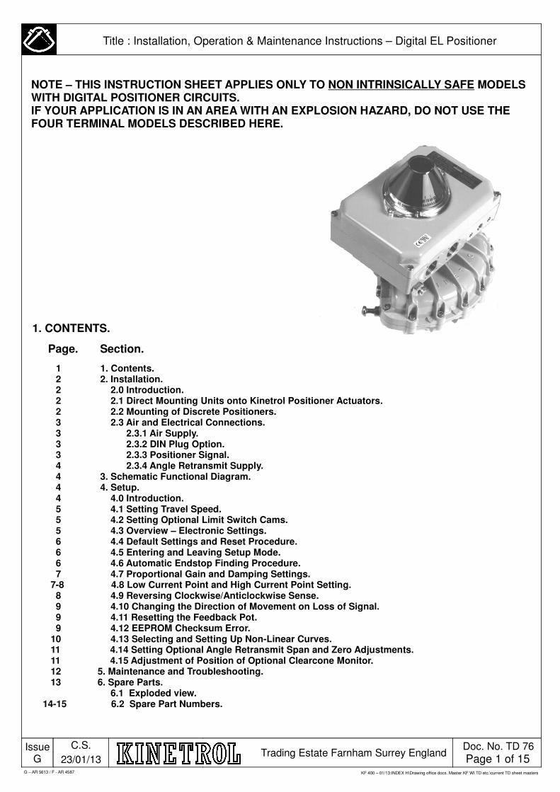
1. CONTENTS.
Page. Section.
1 1. Contents. 2 2. Installation. 2 2.0 Introduction. 2 2.1 Direct Mounting Units onto Kinetrol Positioner Actuators. 2 2.2 Mounting of Discrete Positioners. 3 2.3 Air and Electrical Connections. 3 2.3.1 Air Supply. 3 2.3.2 DIN Plug Option. 3 2.3.3 Positioner Signal. 4 2.3.4 Angle Retransmit Supply. 4 3. Schematic Functional Diagram. 4 4. Setup. 4 4.0 Introduction. 5 4.1 Setting Travel Speed. 5 4.2 Setting Optional Limit Switch Cams. 5 4.3 Overview – Electronic Settings. 6 4.4 Default Settings and Reset Procedure. 6 4.5 Entering and Leaving Setup Mode. 6 4.6 Automatic Endstop Finding Procedure. 7 4.7 Proportional Gain and Damping Settings. 7-8 4.8 Low Current Point and High Current Point Setting. 8 4.9 Reversing Clockwise/Anticlockwise Sense. 9 4.10 Changing the Direction of Movement on Loss of Signal. 9 4.11 Resetting the Feedback Pot. 9 4.12 EEPROM Checksum Error. 10 4.13 Selecting and Setting Up Non-Linear Curves. 11 4.14 Setting Optional Angle Retransmit Span and Zero Adjustments. 11 4.15 Adjustment of Position of Optional Clearcone Monitor. 12 5. Maintenance and Troubleshooting. 13 6. Spare Parts. 6.1 Exploded view. 14-15 6.2 Spare Part Numbers.
KF 400 – 01/13:INDEX H\Drawing office docs. Master KF WI TD etc.\current TD sheet masters
Title : Installation, Operation & Maintenance Instructions – Digital EL Positioner
NOTE – THIS INSTRUCTION SHEET APPLIES ONLY TO NON INTRINSICALLY SAFE MODELS WITH DIGITAL POSITIONER CIRCUITS.IF YOUR APPLICATION IS IN AN AREA WITH AN EXPLOSION HAZARD, DO NOT USE THE FOUR TERMINAL MODELS DESCRIBED HERE.
G – AR 5613 / F - AR 4587

Issue G
C.S.
23/01/13 Trading Estate Farnham Surrey England
Doc. No. TD 76
Page 2 of 15
Title : Installation, Operation & Maintenance Instructions – Digital EL Positioner
2. INSTALLATION
2.0 Introduction Positioners can be supplied direct-mounted, or ready to be direct-mounted, onto Kinetrol rotary actuators, or in stand-alone (discrete) form for fitting via a mount kit to any 90 degree rotary actuator. If the positioner is supplied ready mounted on an actuator, sections 2.1 and 2.2 can be bypassed. Positioner-type Kinetrol actuators (ready for direct mounting of positioners) are available in models 03 to 14 inclusive. These instructions cover the possible use of both metal and moulded feedback coupling. It is expected that most units will contain a moulded coupling.
2.1.1 Move actuator vane to mid travel position, with its output square as shown in Figure 1. This is essential to prevent subsequent error in orienting positioner square.2.1.2 Remove positioner cover, and undo the five M4 slot-headed screws holding the red plastic carrier plate into the body. Disconnect the two wires to the servo valve, and lift out the whole carrier plate assembly complete with shaft and circuit etc.2.1.3 Bolt the positioner body to the actuator in the orientation shown in Figure 1, taking care that O-rings are in place to seal the ports into the actuator, and that the actuator shaft is centred in its hole.2.1.4 (a) Metal coupling versions on 07 and larger models: fit anti-backlash spring over one corner of the actuator square as
shown in Figure 2. (b) Moulded coupling versions: on all direct mount versions, loosen central screw in coupling shaft so that the collet is
not closed, and fit coupling over shaft square.2.1.5 Observe the range of motion available to the positioner shaft, limited by the correct running of the potentiometer quadrant wheel, driven by the stainless steel strap (see Figure 3). Fit the carrier plate/shaft assembly back into the positioner box with the shaft near mid-range, “feeling” the female square in the positioner shaft onto the male actuator square while maintaining its position near mid range. It is essential that the two shafts are correctly oriented relative to each other, since if they are 90 degrees out, the quadrant wheel can be forced too far and damage done to the drive mechanism during subsequent actuator movements. It is possible to fit the positioner correctly with the actuator square at one end of its travel, but experience indicates a high probability of mistaking the direction of movement of the actuator – hence it is strongly advised that the positioner be fitted with the actuator square at the mid-travel position, where there is no ambiguity possible.
Moulded coupling version: Ensure coupling is fully engaged before tightening the central screw (torque to 6 lbf in. to 8lbf in. / 0.7Nm to 0.9 Nm) to close the collet and therefore removing any backlash.
2.2 Mounting of Discrete PositionerDesign and manufacture of the mount kit between positioner and actuator is outside the scope of this document. It is essential that the shaft of the actuator is well aligned with the positioner shaft, and that the two are coupled together with a minimum of backlash – any backlash acts to deteriorate the performance of the positioner/actuator combination.
It is also essential that the 90 degree travel of the actuator moves the positioner shaft through the correct 90 degree range of travel. The easiest way to ensure that this happens is to mount the discrete unit with the lid and indicator in place – set both the actuator and positioner to mid travel, and mate the two in this orientation. Don't take any chances with this, since misorientation of the positioner shaft and consequent movement beyond its designed range of travel will probably result in damage to the positioner pot drive mechanism. With moulded coupling versions, the Namur drive or Kinetrol square option is an insert in the coupling which can be removed by releasing the central screw.
2.1 Mounting of Direct Mounting Units onto Kinetrol Positioner-Type Actuators
G – AR 5613 / F - AR 4587
Issue G
C.S.
23/01/13 Trading Estate Farnham Surrey England
Doc. No. TD 76
Page 3 of 15
Title : Installation, Operation & Maintenance Instructions – Digital EL Positioner
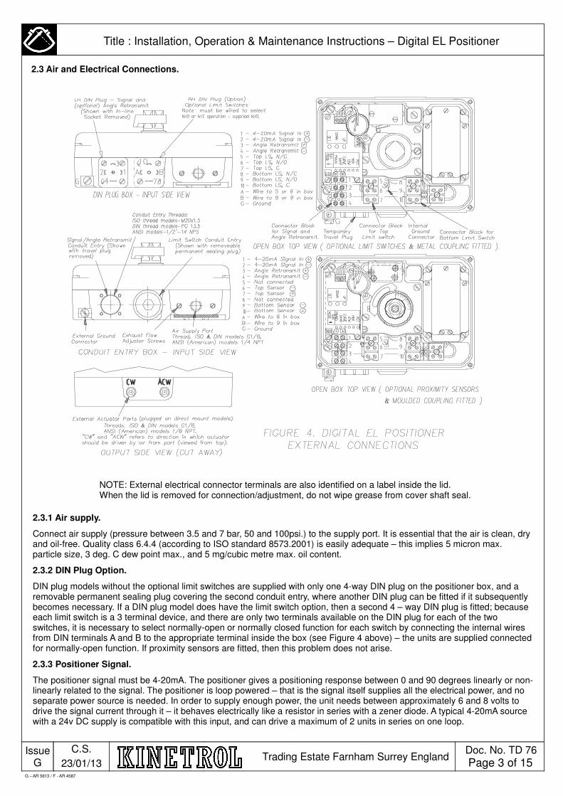
NOTE: External electrical connector terminals are also identified on a label inside the lid. When the lid is removed for connection/adjustment, do not wipe grease from cover shaft seal.
2.3.1 Air supply.
Connect air supply (pressure between 3.5 and 7 bar, 50 and 100psi.) to the supply port. It is essential that the air is clean, dry and oil-free. Quality class 6.4.4 (according to ISO standard 8573.2001) is easily adequate – this implies 5 micron max. particle size, 3 deg. C dew point max., and 5 mg/cubic metre max. oil content.
2.3.2 DIN Plug Option.
DIN plug models without the optional limit switches are supplied with only one 4-way DIN plug on the positioner box, and a removable permanent sealing plug covering the second conduit entry, where another DIN plug can be fitted if it subsequently becomes necessary. If a DIN plug model does have the limit switch option, then a second 4 – way DIN plug is fitted; because each limit switch is a 3 terminal device, and there are only two terminals available on the DIN plug for each of the two switches, it is necessary to select normally-open or normally closed function for each switch by connecting the internal wires from DIN terminals A and B to the appropriate terminal inside the box (see Figure 4 above) – the units are supplied connected for normally-open function. If proximity sensors are fitted, then this problem does not arise.
2.3.3 Positioner Signal.
The positioner signal must be 4-20mA. The positioner gives a positioning response between 0 and 90 degrees linearly or non-linearly related to the signal. The positioner is loop powered – that is the signal itself supplies all the electrical power, and no separate power source is needed. In order to supply enough power, the unit needs between approximately 6 and 8 volts to drive the signal current through it – it behaves electrically like a resistor in series with a zener diode. A typical 4-20mA source with a 24v DC supply is compatible with this input, and can drive a maximum of 2 units in series on one loop.
G – AR 5613 / F - AR 4587
2.3 Air and Electrical Connections.
Issue G
C.S.
23/01/13 Trading Estate Farnham Surrey England
Doc. No. TD 76
Page 4 of 15
Title : Installation, Operation & Maintenance Instructions – Digital EL Positioner
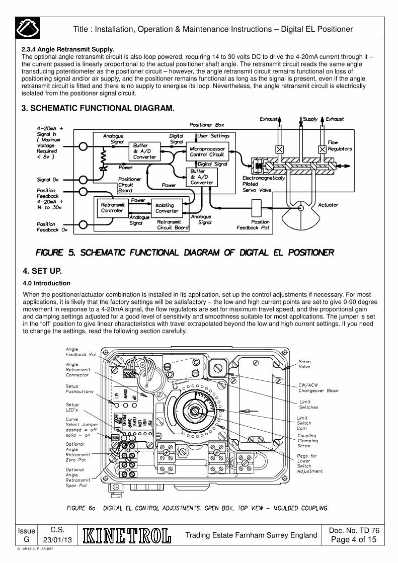
2.3.4 Angle Retransmit Supply. The optional angle retransmit circuit is also loop powered, requiring 14 to 30 volts DC to drive the 4-20mA current through it – the current passed is linearly proportional to the actual positioner shaft angle. The retransmit circuit reads the same angle transducing potentiometer as the positioner circuit – however, the angle retransmit circuit remains functional on loss of positioning signal and/or air supply, and the positioner remains functional as long as the signal is present, even if the angle retransmit circuit is fitted and there is no supply to energise its loop. Nevertheless, the angle retransmit circuit is electrically isolated from the positioner signal circuit.
3. SCHEMATIC FUNCTIONAL DIAGRAM.
4. SET UP.
4.0 Introduction
When the positioner/actuator combination is installed in its application, set up the control adjustments if necessary. For most applications, it is likely that the factory settings will be satisfactory – the low and high current points are set to give 0-90 degree movement in response to a 4-20mA signal, the flow regulators are set for maximum travel speed, and the proportional gain and damping settings adjusted for a good level of sensitivity and smoothness suitable for most applications. The jumper is set in the “off” position to give linear characteristics with travel extrapolated beyond the low and high current settings. If you need to change the settings, read the following section carefully.
G – AR 5613 / F - AR 4587

Issue G
C.S.
23/01/13 Trading Estate Farnham Surrey England
Doc. No. TD 76
Page 5 of 15
Title : Installation, Operation & Maintenance Instructions – Digital EL Positioner
4. SETUP (continued).
4.1 Setting Travel Speed.
Set the travel speed using the exhaust flow adjuster screws (see Figure 4.). This only applies if you want to reduce the speed from its supplied maximum factory setting.
4.2 Setting Optional Limit Switch Cams.
Optional limit switch cams are factory set to give end-of-travel switching with one switch each end. The switching can be set to occur anywhere in the travel range for each switch, by relaxing the cam clamp screw and rotating the cam to position. Set the lower cam first. Take care to avoid the clamp section of a cam striking a switch at any point in the actuator's travel. Two possible types of coupling require slightly different approaches to setting:
4.2.1 Moulded coupling cams, shown in figure 6a, can be adjusted using light pressure to rotate in 1 degree increments. Adjust the lower cam first using a screwdriver to lever against special pegs moulded into the carrier plate or use finger pressure. Secondly move the upper cam using finger pressure only. Graduated marks on the top of the coupling are provided to gauge the position of the actuator with the lid removed. This can be lined up with an arrow marked on the servo valve lid.
4.2.2 Metal coupling cams are adjusted by releasing the screw shown in figure 6b, moving to desired position and re tightening. Set the lever cam first. Ensure the clamp section of the cam does not strike a switch at any part in the actuator's travel.
4.3 Overview – Electronic Settings.
The EL digital positioner circuit can operate to give actuator position accurately proportional to input current, or it can operate as a non-linear device accurately following one of a number of fast open, or slow open, exponential curves. Linear or non-linear, it can easily be calibrated to scale its operating line, or curve, between any two user defined points in its operating range. The positioner circuit is powered entirely from the 4-20mA input signal. It is tuned and calibrated by simple and quick operation of its three push buttons, with red LED (light emitting diode) indication of the selected parameter. The positioner can also calibrate itself automatically to the actuator or valve endstops. The actuator dynamic response can be optimised by simple adjustment of the positioner circuit proportional gain and damping variables. All tuning and calibration data is stored digitally, and is retained in non-volatile memory, so that the positioner powers up with all the same settings it had when last powered down.
The positioner may be operated either as a linear or non-linear device. Non-linear operation is enabled by fitting a jumper link to the positioner with the positioner (and position retransmit if fitted) powered down (i.e. input current at 0 mA). When the positioner is powered up with the link “on” (see figure 6 for its position), it will then operate as a non-linear device for as long as it remains powered up. Conversely, when the positioner is powered up with the link “off”, it will operate as a linear device as long as it remains powered up. Changing the link from “on” to “off” or vice-versa while the circuit remains powered up will not cause a change from non-linear to linear operation – the position of the link is only effective during power up.
Whether operating as a linear or non-linear device, the positioner has two distinct modes of operation, Normal Mode and Setup Mode.
In Normal Mode the positioner simply positions its actuator in response to the 4-20mA input signal. When the positioner is powered up, it always starts in Normal Mode. In Normal Mode, the LEDS are not lit. The positioner stays in Normal Mode until Setup Mode is selected manually.
In Setup Mode the positioner can be tuned and calibrated for its application. Although the position is still controlled, it does not always follow the input signal. When tuning and calibration is complete the positioner should always be returned to Normal Mode for continued normal use.
Operating in Setup Mode is described in the following sections.
G – AR 5613 / F - AR 4587
Issue G
C.S.
23/01/13 Trading Estate Farnham Surrey England
Doc. No. TD 76
Page 6 of 15
Title : Installation, Operation & Maintenance Instructions – Digital EL Positioner
4. SETUP (continued).
4.4 Default Settings and Reset Procedure.
The positioner can be reset with a complete set of default values when powered up in any operating mode, by pressing all three push buttons (UP, DOWN and SET) simultaneously. This will overwrite all the existing proportional gain, damping, curve selection and calibration data with default values which are suitable for a typical forward acting linear positioner with mid range values for proportional gain and damping (but not necessarily optimised for a particular application). This procedure is useful in the case where errors in calibration have resulted in positioner behaviour which seems incomprehensible, and it is necessary to return to a predictable basic setup. The positioner should always be tuned and then recalibrated immediately after this resetting process.
4.5 Entering and Leaving Setup Mode.
Setup Mode is selected from Normal Mode by simultaneously pressing the UP and the SET push buttons (i.e. the two outside ones). This causes the LED labelled PGAIN (short for Proportional Gain) to light continuously. In Setup Mode, each of the parameters in the list below may be selected for adjustment by pressing the UP or DOWN push buttons as required. The parameter selected is indicated on the positioner circuit by an LED lighting next to the parameter's name.
PGAIN - Proportional Gain
DAMP - Damping
CURVE - Non-Linear Curve Selection
LOW - Low Current Point Calibration
HIGH - High Current Point Calibration
POT - Feedback Potentiometer Bottom of Range Setting
When the required parameter has been selected for adjustment, the SET push button is pressed to allow adjustments to be made – the LED next to the selected parameter starts to blink, to indicate that Adjust Mode is active. Operation in the Adjust Mode for each parameter is described in the following sub-sections. To leave Adjust Mode, press the SET push button again – this causes the LED to light continuously, and allows movement between parameters again.
Note: There is no Adjust Mode for the feedback potentiometer bottom of range setting, but the automatic end stop finding sequence can be initiated when this parameter is selected.
To leave set up mode (when the adjustments have been made and the SET push button pressed to leave Adjust Mode), press the DOWN push button repeatedly to move down the parameter's and off the end of the list – at this point the LEDs cease to light, and the positioner is back in Normal Mode.
4.6 Automatic Endstop Finding Procedure.
The positioner can automatically calibrate itself to range between any mechanical end stops (either the built-in actuator stops, or any external stops built into the application). During the finding sequence, the positioner moves the actuator up to the top and bottom stops and records their positions. It then uses these positions as the HIGH and LOW positions in the calibration data, and applies the existing values for HIGH and LOW current input. Note that if the positioner was reverse acting before the sequence, it remains so after the sequence.
The End Stop Finding Sequence starts when the POT parameter is selected, and the UP and SET push buttons (i.e. the two outside push buttons) are pressed simultaneously. The POT LED starts to blink, and the actuator moves steadily up scale from its set position. When its movement is stopped by the the top physical end stop, the positioner waits briefly, then moves the actuator steadily downscale until it runs against the bottom physical endstop, where again it waits briefly, and finally moves quickly back to the set position. The calibration data is written to non-volatile memory while the actuator pauses at its bottom stop.
If the positioner is in service on an application where excursions to the end stops will be disruptive, avoid initiating this sequence.
G – AR 5613 / F - AR 4587
Issue G
C.S.
23/01/13 Trading Estate Farnham Surrey England
Doc. No. TD 76
Page 7 of 15
Title : Installation, Operation & Maintenance Instructions – Digital EL Positioner
4. SETUP (continued).
4.7 Proportional Gain and Damping Settings (for Smoothness and Sensitivity).
Select Setup Mode, and the first parameter selected is automatically PGAIN – Proportional Gain. Press the SET push button, and the PGAIN LED will start blinking. The value of the parameter can now be increased or decreased by pressing the UP or DOWN push buttons as required. There are twenty nine (29) PGAIN settings which can be selected, the setting altering by a factor of about 1.1 each time the UP or DOWN button is pressed. The default setting lies in the middle of the range, giving fourteen settings above and fourteen below. Any button presses beyond the last (fourteenth) will have no effect.
Note: As soon as the UP or DOWN push button is pressed, the new PGAIN value is stored in non-volatile memory and is retained even if the positioner is de-energised before leaving Adjust and Setup Modes.
The positioner is active while adjusting the PGAIN setting, and continues to follow the input signal. This gives the opportunity to change the input signal in a manner typical of the application, and to observe qualitatively the response of the positioner, and how it has been affected by changing the PGAIN setting, so as to optimise the response. Pressing the UP button maximises the sensitivity and accuracy, at the cost of increased jerkiness of response when the signal is ramped smoothly, and if you go too far this increases the proportional gain so much that the positioner becomes unstable and hunts around the position set by the signal. Pressing the DOWN button maximises smoothness during ramping of the signal, at the cost of losing rapidity of response to small changes in signal. When the right setting has been found, press the SET button again to leave Adjust Mode – the PGAIN LED will now light continuously.
The DAMP (damping) parameter should be set after the PGAIN has been optimised. In Setup Mode select the DAMP parameter (second up from PGAIN) by pressing the UP button until the DAMP LED lights continuously. Press the SET button to select Adjust Mode, and the DAMP LED will blink. Damping can be increased and decreased by pressing the UP or DOWN buttons. There are twenty nine damping settings which can be selected, the setting altering by a factor of 1.1 each time the UP or DOWN pushbutton is pressed. The default setting lies in the middle of the range, giving fourteen settings above and fourteen below. Any button presses beyond the last (fourteenth) setting will have no effect.
Note: As soon as the UP or DOWN button is pressed, the new DAMP value is stored in non-volatile memory, and is retained even if the positioner is de-energised before leaving Adjust and Setup Modes.
The positioner is active while adjusting the DAMP setting, and continues to follow the input signal. This allows the signal to be waggled to optimise the response while still adjusting the DAMP setting. Try stepping the signal suddenly so that the positioner approaches setpoint at full speed having travelled 45 degrees or more, and adjust the DAMP setting to just avoid overshoot here. Try this travelling up and downscale. When the right setting has been found, press the SET button again to leave Adjust Mode – the DAMP LED will now light continuously.
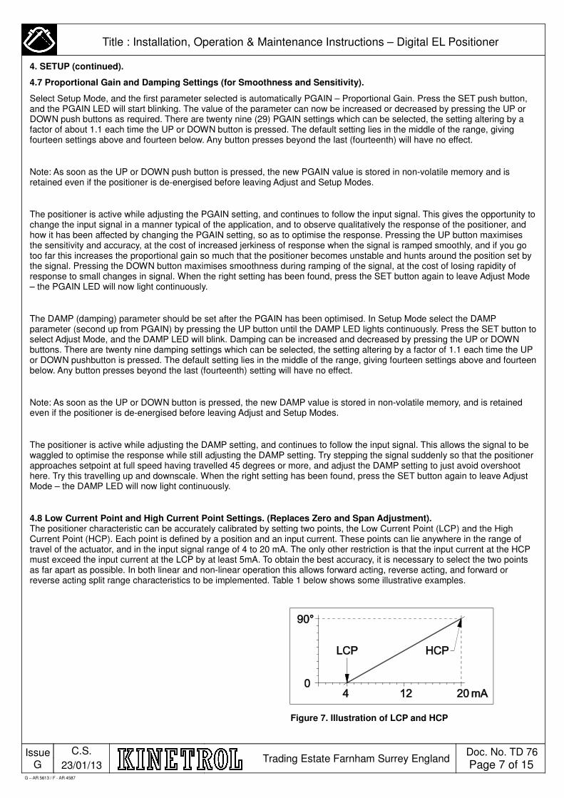
4.8 Low Current Point and High Current Point Settings. (Replaces Zero and Span Adjustment). The positioner characteristic can be accurately calibrated by setting two points, the Low Current Point (LCP) and the High Current Point (HCP). Each point is defined by a position and an input current. These points can lie anywhere in the range of travel of the actuator, and in the input signal range of 4 to 20 mA. The only other restriction is that the input current at the HCP must exceed the input current at the LCP by at least 5mA. To obtain the best accuracy, it is necessary to select the two points as far apart as possible. In both linear and non-linear operation this allows forward acting, reverse acting, and forward or reverse acting split range characteristics to be implemented. Table 1 below shows some illustrative examples.
Figure 7. Illustration of LCP and HCP
G – AR 5613 / F - AR 4587
Issue G
C.S.
23/01/13 Trading Estate Farnham Surrey England
Doc. No. TD 76
Page 8 of 15
Title : Installation, Operation & Maintenance Instructions – Digital EL Positioner
4. SETUP (continued).
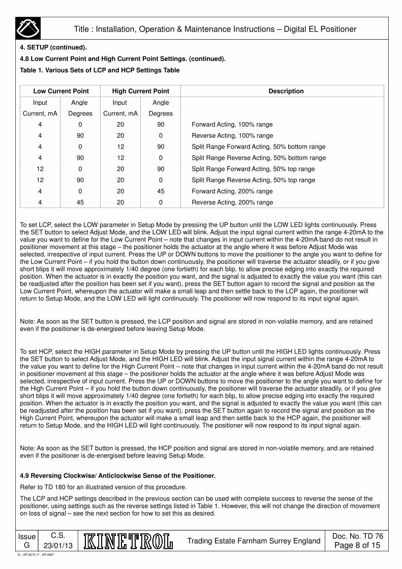
4.8 Low Current Point and High Current Point Settings. (continued).
Table 1. Various Sets of LCP and HCP Settings Table
To set LCP, select the LOW parameter in Setup Mode by pressing the UP button until the LOW LED lights continuously. Press the SET button to select Adjust Mode, and the LOW LED will blink. Adjust the input signal current within the range 4-20mA to the value you want to define for the Low Current Point – note that changes in input current within the 4-20mA band do not result in positioner movement at this stage – the positioner holds the actuator at the angle where it was before Adjust Mode was selected, irrespective of input current. Press the UP or DOWN buttons to move the positioner to the angle you want to define for the Low Current Point – if you hold the button down continuously, the positioner will traverse the actuator steadily, or if you give short blips it will move approximately 1/40 degree (one fortieth) for each blip, to allow precise edging into exactly the required position. When the actuator is in exactly the position you want, and the signal is adjusted to exactly the value you want (this can be readjusted after the position has been set if you want), press the SET button again to record the signal and position as the Low Current Point, whereupon the actuator will make a small leap and then settle back to the LCP again, the positioner will return to Setup Mode, and the LOW LED will light continuously. The positioner will now respond to its input signal again.
Note: As soon as the SET button is pressed, the LCP position and signal are stored in non-volatile memory, and are retained even if the positioner is de-energised before leaving Setup Mode.
To set HCP, select the HIGH parameter in Setup Mode by pressing the UP button until the HIGH LED lights continuously. Press the SET button to select Adjust Mode, and the HIGH LED will blink. Adjust the input signal current within the range 4-20mA to the value you want to define for the High Current Point – note that changes in input current within the 4-20mA band do not result in positioner movement at this stage – the positioner holds the actuator at the angle where it was before Adjust Mode was selected, irrespective of input current. Press the UP or DOWN buttons to move the positioner to the angle you want to define for the High Current Point – if you hold the button down continuously, the positioner will traverse the actuator steadily, or if you give short blips it will move approximately 1/40 degree (one fortieth) for each blip, to allow precise edging into exactly the required position. When the actuator is in exactly the position you want, and the signal is adjusted to exactly the value you want (this can be readjusted after the position has been set if you want), press the SET button again to record the signal and position as the High Current Point, whereupon the actuator will make a small leap and then settle back to the HCP again, the positioner will return to Setup Mode, and the HIGH LED will light continuously. The positioner will now respond to its input signal again.
Note: As soon as the SET button is pressed, the HCP position and signal are stored in non-volatile memory, and are retained even if the positioner is de-energised before leaving Setup Mode.
4.9 Reversing Clockwise/ Anticlockwise Sense of the Positioner.
Refer to TD 180 for an illustrated version of this procedure.
The LCP and HCP settings described in the previous section can be used with complete success to reverse the sense of the positioner, using settings such as the reverse settings listed in Table 1. However, this will not change the direction of movement on loss of signal – see the next section for how to set this as desired.
Low Current Point High Current Point Description
Input Angle Input Angle
Current, mA Degrees Current, mA Degrees
4 0 20 90 Forward Acting, 100% range
4 90 20 0 Reverse Acting, 100% range
4 0 12 90 Split Range Forward Acting, 50% bottom range
4 90 12 0 Split Range Reverse Acting, 50% bottom range
12 0 20 90 Split Range Forward Acting, 50% top range
12 90 20 0 Split Range Reverse Acting, 50% top range
4 0 20 45 Forward Acting, 200% range
4 45 20 0 Reverse Acting, 200% range
G – AR 5613 / F - AR 4587

Issue G
C.S.
23/01/13 Trading Estate Farnham Surrey England
Doc. No. TD 76
Page 9 of 15
Title : Installation, Operation & Maintenance Instructions – Digital EL Positioner
4. SETUP (continued).
4.10 Changing the Direction of Movement on Loss of Signal.
On being de-energised with air supply still fully pressurised (i.e. on disconnection of the signal, or when the signal falls below 3.5mA), the positioner moves the actuator in a direction set by the de-energised position of the servo valve. This direction of movement is independent of the LCP and HCP settings described in the sections above.
Movement on loss of air pressure is unpredictable for double acting positioners – if position needs to be held on loss of pressure, then it is necessary to order an external pressure sensing lockout valve assembly, and if a definite end of travel position is required on loss of pressure, then it is necessary to order a spring return unit.
On double acting actuators the unit is factory set to move clockwise (as viewed from the positioner lid) on loss of signal.
On spring return actuators the unit is factory set to move in the spring return direction on loss of air, or on loss of both air and signal, but it is set to move clockwise (as viewed from the positioner lid) irrespective of spring direction on loss of signal only.
To change the direction of movement on loss of signal, carry out the following steps: (1) Disconnect air supply and signal. (2) Undo screw holding down changeover block (see Figure 6). (3) Rotate changeover block 90 degrees, taking care to keep rubber gasket lined up with holes in body. (4) Re-tighten screw holding down changeover block making sure it remains in alignment with the body. (5) Undo outer two angle pot wire terminal screws, swap blue and yellow wires over to reverse sense of pot connection, and re-tighten screws. (6) Re-connect air supply and signal, and carry out Resetting Feedback Pot procedure (see next section).
4.11 Resetting the Feedback Pot.
This procedure is necessary only if the pot has been moved from its factory setting, or if the direction of movement on loss of signal has been changed as instructed in the previous section.
The positioner circuit needs the feedback pot to be positioned at the correct angle, such that its wiper reads the right voltage when the actuator is against its downscale endstop – i.e. against the endstop it reaches when the air supply is connected, but the signal is disconnected. The circuit itself can identify this voltage when it is powered up in Setup Mode with the POT parameter selected – when the pot is adjusted correctly, the POT LED changes from lighting continuously to blinking.
To set the pot, first move the actuator to the downscale endstop by connecting the air supply and disconnecting the signal. When it is in this position, hold it there by fitting a keeper plate if the unit has a spring return set to fail against the opposite stop, or by simply disconnecting the air supply if the unit is double acting or has a spring return set to fail against this stop. Re-connect the signal, and set to any current between 4 and 20mA. Select Setup Mode, and press the UP button until the POT LED lights continuously. Unclamp the pot clamp screws, taking care not to unscrew them too far such that they disengage from the nuts in the carrier plate. Rotate the pot until the POT LED changes from continuous to blinking illumination. Re-tighten the clamp screws, and reconnect the air supply. If the unit needed a keeper plate, drive it downscale by disconnecting the signal, and then remove the keeper plate with the air supply on.
4.12 EEPROM Checksum error Each time calibration or setting data is written to EEPROM (non-volatile memory) by the positioner circuit, a checksum of all EEPROM data is calculated and written to EEPROM. Hence if there is a power supply (i.e. signal) interruption during the EEPROM write procedure, the checksum will not be written correctly, or at all. After the interruption, during its initialisation routines the positioner carries out a checksum calculation of the data stored in EEPROM. If the newly calculated checksum and the stored checksum are not identical, the positioner enters an error routine, and does not start Normal Mode operation. This condition is indicated by the LEDs lighting one after the other in sequence. If this condition is achieved, carry out the reset procedure described in section 4.3, and then recalibrate as detailed in sections 4.5 to 4.8.
G – AR 5613 / F - AR 4587
Issue G
C.S.
23/01/13 Trading Estate Farnham Surrey England
Doc. No. TD 76
Page 10 of 15
Title : Installation, Operation & Maintenance Instructions – Digital EL Positioner
4. SETUP (continued).
4.13 Selecting and Setting Up Non-Linear Curves.
The positioner may be operated either as a linear or non-linear device. Non-linear operation is enabled by fitting a jumper link to the positioner with the positioner (and position retransmit if fitted) powered down (i.e. input current at 0 mA). When the positioner is powered up with the link “on” (see figure 6 for its position), it will then operate as a non-linear device for as long as it remains powered up. Conversely, when the positioner is powered up with the link “off”, it will operate as a linear device as long as it remains powered up. Changing the link from “on” to “off” or vice-versa while the circuit remains powered up will not cause a change from non-linear to linear operation – the position of the link is only effective during power up.
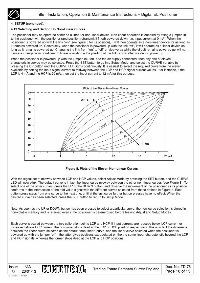
When the positioner is powered up with the jumper link “on” and the air supply connected, then any one of eleven characteristic curves may be selected. Press the SET button to go into Setup Mode, and select the CURVE variable by pressing the UP button until the CURVE LED lights continuously. It is easiest to select the required curve from the eleven available by setting the input signal current to midway between the LCP and HCP signal current values – for instance, if the LCP is 4 mA and the HCP is 20 mA, then set the input current to 12 mA for this purpose.
Figure 8. Plots of the Eleven Non-Linear Curves
With the signal set at midway between LCP and HCP values, select Adjust Mode by pressing the SET button, and the CURVE LED will now blink. The default curve is in fact the linear curve midway between the other non-linear curves (see Figure 8). To select one of the other curves, press the UP or the DOWN button, and observe the movement of the positioner as its position conforms to the intersection of the mid value signal with the different curves selected from those defined in Figure 8. Each button press steps from one curve to the next one, until at the last curve further button presses have no effect. When the desired curve has been selected, press the SET button to return to Setup Mode.
Note: As soon as the UP or DOWN button has been pressed to select a particular curve, the new curve selection is stored in non-volatile memory and is retained even if the positioner is de-energised before leaving Adjust and Setup Modes.
Each curve is scaled between the two calibration points LCP and HCP. If input currents are reduced below LCP current or increased above HCP current, the positioner stops dead at the LCP or HCP position respectively. This is in fact the difference between the linear curve selected as the default “non-linear” curve, and the linear curve selected when the positioner is powered up with the jumper “off” - the latter gives positions extrapolated on the the same linear characteristic beyond the LCP and HCP signals, whereas the former stops dead at the LCP and HCP positions.
G – AR 5613 / F - AR 4587
UPUP
DOWNDOWN
00
1010
2020
3030
4040
5050
6060
7070
8080
90
4400 88 1212 2020 mAmA1616
11
-3-3-4
-5
Defau lt
22
-2-2
-1-1
33
4455
Plots of the Eleven Non-Linear CurvesPlots of the Eleven Non-Linear Curves
00
º
Issue G
C.S.
23/01/13 Trading Estate Farnham Surrey England
Doc. No. TD 76
Page 11 of 15
Title : Installation, Operation & Maintenance Instructions – Digital EL Positioner
4. SETUP (continued).
4.14 Setting Optional Angle Retransmit Span and Zero Adjustments.
The angle retransmit circuit is mounted directly underneath the positioner circuit, and its ZERO and SPAN preset pots are accessible using a small instrument screwdriver through the two access holes in the positioner circuit (see Figure 6). Connect the air supply, positioner signal and angle retransmit reader supply. To set the ZERO, move the positioner to its minimum signal position (usually 4mA), and set the ZERO preset pot to give the desired retransmit current. Then set the SPAN by moving the positioner to its maximum signal position (usually 20mA), and adjusting the SPAN pre-set pot to give the desired retransmit current. Recheck and read just these two settings until both are correct – as the SPAN is adjusted, it has a small effect on the ZERO reading, and vice-versa, so a few readjustments may be necessary.
The angle retransmit circuit is fitted with a jumper, which should be fitted to bridge its two pins if you want the circuit to read 4-20mA over 45 degrees or near, rather than the usual 90 degrees. The range adjustment pot is adjustable to give ranges in between these two values. To gain access to this jumper, it is necessary to remove the whole carrier plate assembly from the positioner – see Section 2.1 for instructions on this.
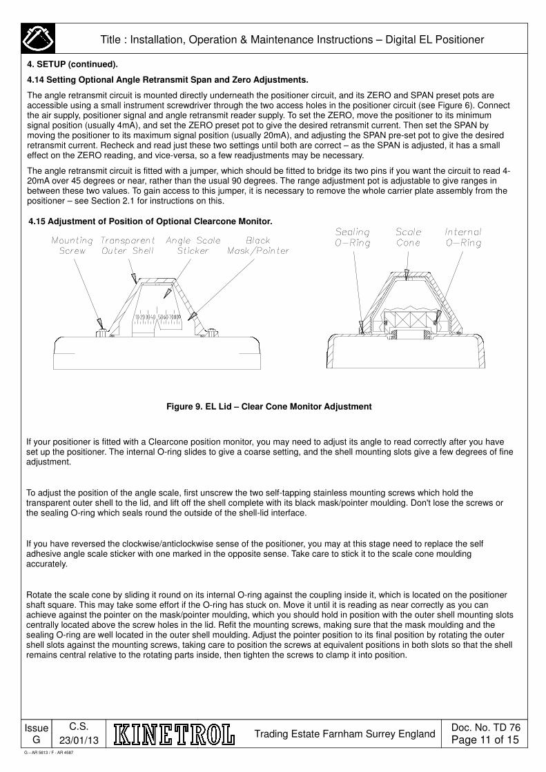
4.15 Adjustment of Position of Optional Clearcone Monitor.
Figure 9. EL Lid – Clear Cone Monitor Adjustment
If your positioner is fitted with a Clearcone position monitor, you may need to adjust its angle to read correctly after you have set up the positioner. The internal O-ring slides to give a coarse setting, and the shell mounting slots give a few degrees of fine adjustment.
To adjust the position of the angle scale, first unscrew the two self-tapping stainless mounting screws which hold the transparent outer shell to the lid, and lift off the shell complete with its black mask/pointer moulding. Don't lose the screws or the sealing O-ring which seals round the outside of the shell-lid interface.
If you have reversed the clockwise/anticlockwise sense of the positioner, you may at this stage need to replace the self adhesive angle scale sticker with one marked in the opposite sense. Take care to stick it to the scale cone moulding accurately.
Rotate the scale cone by sliding it round on its internal O-ring against the coupling inside it, which is located on the positioner shaft square. This may take some effort if the O-ring has stuck on. Move it until it is reading as near correctly as you can achieve against the pointer on the mask/pointer moulding, which you should hold in position with the outer shell mounting slots centrally located above the screw holes in the lid. Refit the mounting screws, making sure that the mask moulding and the sealing O-ring are well located in the outer shell moulding. Adjust the pointer position to its final position by rotating the outer shell slots against the mounting screws, taking care to position the screws at equivalent positions in both slots so that the shell remains central relative to the rotating parts inside, then tighten the screws to clamp it into position.
G – AR 5613 / F - AR 4587
Issue G
C.S.
23/01/13 Trading Estate Farnham Surrey England
Doc. No. TD 76
Page 12 of 15
Title : Installation, Operation & Maintenance Instructions – Digital EL Positioner
5. MAINTENANCE AND TROUBLESHOOTING
The EL positioner is designed to be maintenance free during a long life, if it is supplied with clean, dry oil free air, and electrical signals free of noise and high voltage spikes.
When the lid is removed, take care not to wipe all grease from shaft lip seal.
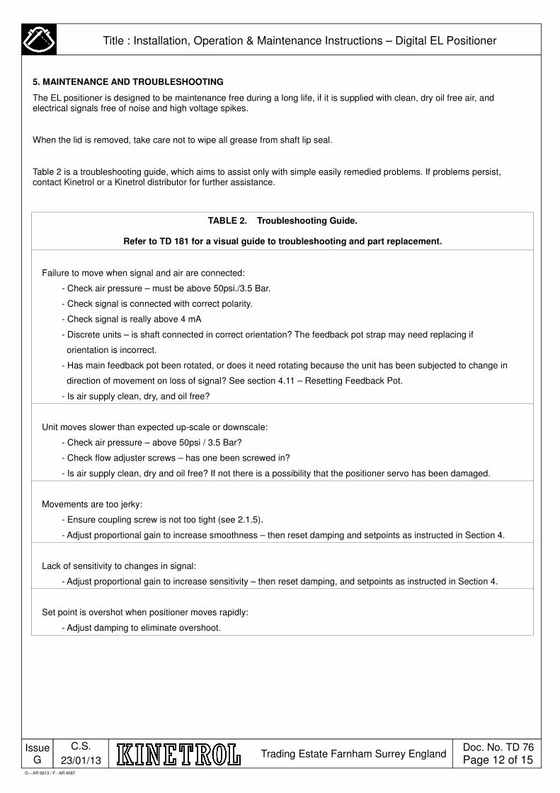
Table 2 is a troubleshooting guide, which aims to assist only with simple easily remedied problems. If problems persist, contact Kinetrol or a Kinetrol distributor for further assistance.
TABLE 2. Troubleshooting Guide.
Refer to TD 181 for a visual guide to troubleshooting and part replacement.
Failure to move when signal and air are connected:
- Check air pressure – must be above 50psi./3.5 Bar.
- Check signal is connected with correct polarity.
- Check signal is really above 4 mA
- Discrete units – is shaft connected in correct orientation? The feedback pot strap may need replacing if
orientation is incorrect.
- Has main feedback pot been rotated, or does it need rotating because the unit has been subjected to change in
direction of movement on loss of signal? See section 4.11 – Resetting Feedback Pot.
- Is air supply clean, dry, and oil free?
Unit moves slower than expected up-scale or downscale:
- Check air pressure – above 50psi / 3.5 Bar?
- Check flow adjuster screws – has one been screwed in?
- Is air supply clean, dry and oil free? If not there is a possibility that the positioner servo has been damaged.
Movements are too jerky:
- Ensure coupling screw is not too tight (see 2.1.5).
- Adjust proportional gain to increase smoothness – then reset damping and setpoints as instructed in Section 4.
Lack of sensitivity to changes in signal:
- Adjust proportional gain to increase sensitivity – then reset damping, and setpoints as instructed in Section 4.
Set point is overshot when positioner moves rapidly:
- Adjust damping to eliminate overshoot.
G – AR 5613 / F - AR 4587
Issue G
C.S.
23/01/13 Trading Estate Farnham Surrey England
Doc. No. TD 76
Page 13 of 15
Title : Installation, Operation & Maintenance Instructions – Digital EL Positioner
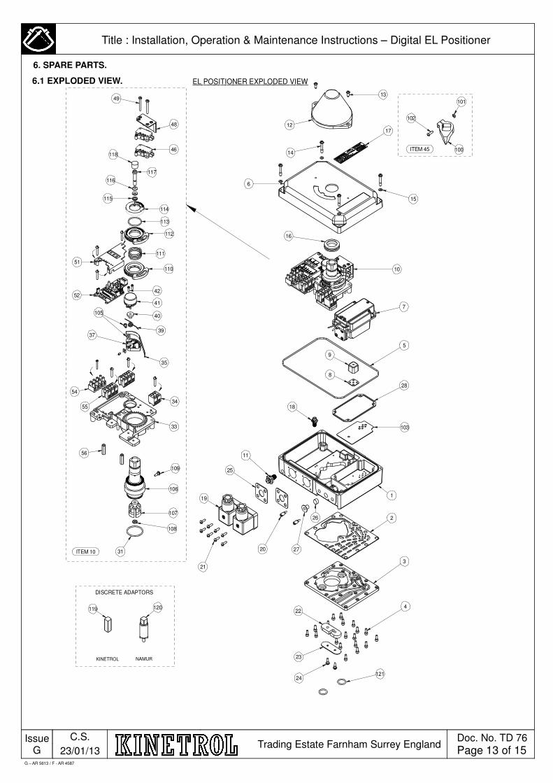
ITEM 45
EL POSITIONER EXPLODED VIEW
31
108
107
106
109
56
54
55
35
39
40
41
42
33
34
52
51
110
111
112
113
114
115
116
117
118
49
48
ITEM 10
12
6
16
10
17
24
23
22
3
2
119
25
11
20 27
26
103
28
5
9
8
18
7
4
21
102
100
101
NAMUR
DISCRETE ADAPTORS
KINETROL
119 120
13
15
121
1446
105
37
G – AR 5613 / F - AR 4587
6. SPARE PARTS.
6.1 EXPLODED VIEW.

Issue G
C.S.
23/01/13 Trading Estate Farnham Surrey England
Doc. No. TD 76
Page 14 of 15
Title : Installation, Operation & Maintenance Instructions – Digital EL Positioner
G – AR 5613 / F - AR 4587
6.2 EL POSITIONER SPARE PART LIST.

Issue G
C.S.
23/01/13 Trading Estate Farnham Surrey England
Doc. No. TD 76
Page 15 of 15
Title : Installation, Operation & Maintenance Instructions – Digital EL Positioner
G – AR 5613 / F - AR 4587
6.2 SPARE PART LIST CONTINUED.