Embed Size (px)
Citation preview

Paper IBC 19-4
36th International Bridge Conference
Gaylord National Resort, National Harbor, MD
June 10-12, 2019
Title: Case Studies of Bridge Failure due to Scour and Prevention of Future
Failures
Roger L. Simpson, Ph.D., P.E., M.ASCE corresponding author
Email: [email protected]
Phone: (540)-961-3005
FAX: 866-223-8673
Gwibo Byun, Ph.D.
Email: [email protected]
Phone: (540)-553-5139
FAX: 866-223-8673
Abstract
For US bridges over water, 70% are NOT designed to withstand scour, 21000 are currently“scour critical”, and 80% of bridge failures are due to scour, often during floods and peak flowevents which are becoming more common with climate change (Flint et al., 2017). Lin et al.(2013) examined 36 bridge failures due to scour in terms of structural, hydraulic, andgeotechnical conditions. Local scour, channel migration scour, and contraction scour wereresponsible for 78% of failures. Sadly, many lives were lost during these failures.
ALL bridge scour failures are produced by large-scale scouring vortices formed at piers andabutments that bring high velocity water down to the river bed. Since the scouring forces on thebed material vary with the SQUARE of the local velocity, it is clear that the best scourcountermeasure is to PREVENT THE SCOURING VORTICES.
The purpose of this paper is to show that scouring-vortex-preventing designs would have

prevented ALL of the bridge scour failures and will prevent future failures at all flow speeds.Designs for various types of piers, footings, abutments, angles of attack, river swirl, and bedconditions have been tested at model scale and some at full scale and show no scouring vortices.Computational fluid dynamic studies show that no scouring vortices are produced. Otheradvantages of these designs are: much lower present value of all costs, lower river levels andflow blockage, lower possibility for debris and ice buildup, and greater protection of piers andabutments against impact loads.
Introduction
Removal of river bed substrate around bridge pier and abutment footings, also known as scour,presents a significant cost and risk in the maintenance of many bridges throughout the world andis one of the most common causes of highway bridge failures (1). For US bridges over water,70% are NOT designed to withstand scour, 21000 are currently “scour critical”, and 80% ofbridge failures are due to scour, often during floods and peak flow events over a short time,which are becoming more common with climate change, as discussed in detail by Flint et al. (2).Lin et al. (3) examined 36 bridge failures due to scour in terms of structural, hydraulic, andgeotechnical conditions. Local scour, channel migration scour, and contraction scour wereresponsible for 78% of failures. Sadly, many lives were lost during these failures.
This has motivated research on the causes of scour at bridge piers and abutments (4) and ledbridge engineers to develop numerous scour countermeasures that attempt to reduce the risk ofcatastrophe. Unfortunately, all previously used scour countermeasures are temporary responsesthat require many recurring costs and do not prevent the formation of scouring vortices, which isthe root cause of the local scour (5,6). Consequently, soil and rocks around the foundations ofbridge abutments and piers are loosened and carried away by the flow during floods, which maycompromise the integrity of the structure. Even designing bridge piers or abutments with theexpectation of some scour is highly uncertain, since a recently released study (5) showed hugeuncertainties in scour data from hundreds of experiments.
None of the conservative current bridge pier and abutment footing or foundation designs preventscouring vortices, which are created when the flow interacts with underwater structures, so theprobability of scour during high water or floods is present in all previous designs. Baker et al. (7)point out that designs to avoid catastrophes should be based on extreme events and that there is aneed for more physical understanding of flood processes and situations, rather than just usingstatistics.
Here two well publicized and investigated bridge failures due to scour are discussed: theSchoharie Creek Bridge pier collapse of 1987 and the Loon Mountain abutment collapse of2011. These failures could have been avoided if scour-vortex-prevention designs had been used.
The nature of scouring vortices is briefly discussed. ALL bridge scour failures are produced bylarge-scale scouring vortices formed at piers and abutments that bring high velocity water downto the river bed. Since the scouring forces on the bed material vary with the SQUARE of thelocal velocity, it is clear that the best scour countermeasure is to PREVENT THE SCOURINGVORTICES.

After this, applications of the scAURTM special streamlined fairings and the VorGAURTM vortexgenerators that prevent scouring vortices will be discussed for the Schoharie Creek Bridge andLoon Mountain Bridge cases. The costs of these bridge failures and costs for application of thescAURTM special streamlined fairings and VorGAURTM vortex generators will be discussed. Theconclusions point out that that scouring-vortex-preventing designs would have prevented ALL ofthe bridge scour failures, will prevent future failures at all flow speeds, have much lower presentvalue of all costs, lower river levels and flow blockage, lower possibility for debris and icebuildup, and greater protection of piers and abutments against impact loads.
Failure of the Schoharie Creek Bridge
The early April rains of 1987 were intense. Streams that were already high from rainfall andsnow melt from the previous week rose quickly with the new amounts of water. Streams flooded.Witnesses said the Schoharie Creek, normally just six feet deep and shallow enough to drive afarm tractor through, was more than 10 feet above flood level and about 25 feet deep. Accordingto a 1989 report by the U.S. Geological Survey of the Department of the Interior, the 1987 floodalong the Schoharie was the third largest since record tabulation began during the early 1900s;only the floods of October 1955 and March 1980 were bigger. A 60-foot section of the 540-foot-long bridge fell 110 feet into the creek about 10:45 a.m (8).
Using a number of referenced investigations, Lin et al. (3) discussed the Schoharie Creek Bridgecollapse of April 5, 1987 that left 10 people dead. This bridge had two spans over the SchoharieCreek near Amsterdam, New York. The bridge suffered severe scour after a spring flood, whichcaused collapse of Pier 3 and subsequent Spans 3 and 4 (Figures 1, 2, and 3). The 50-year floodevent with a velocity of 4.6 m/s was a result of a combination of heavy rainfall and snowmelt,according to the NTSB (9). The high flood rate created an approximately 3 m deep scour holearound Pier 3. The Schoharie Creek Bridge was supported by spread footings with limitedembedment into the riverbed. The spread footing under Pier 3 rested on highly erodible soils(i.e. layers of gravel, sand, and silt). Causes of the bridge failure were investigated after thebridge collapse.
It was found that the collapse was attributable to a number of design and maintenancedeficiencies, such as insufficient embedment of the spread footing, the erodible bearing soillayer, the use of erodible backfill for the footing excavation, and inadequate riprap protection,inspection, and maintenance. The scour was aggravated by a combination of other factors. Forexample, the flood velocity was higher than anticipated in the original design; debris accelerateddownward scour; berms increased the floodwater under the bridge; and a high hydraulic gradientformed between upstream and downstream in the spring. Failure was also related to insufficientdesign of the bridge structure for scour conditions. For example, the superstructure bearingsallowed for the uplift and slide of the superstructure from the piers; simple spans without anyredundancy were utilized; the lightly reinforced concrete piers had limited ductility; and deficientplinth reinforcement resulted in sudden cracking of the plinth instead of a hinging failure.
In a UPI press report (10) on April 2, 1988, the National Transportation Safety Board reviewed aNY State Disaster Preparedness Commission report that blamed erosion by floodwaters that ate

away the soil around and beneath the bridge's supports and shallow 'spread' footings of thebridge piers. Unlike supports anchored into bedrock by pilings, the span's footings rested on soil.Further, the report concluded, while the bridge's design drawings called for heavy rock fill --called 'riprap' -- to be placed around the footings beneath the stream bed, soil was found thereinstead. And much of the riprap that was put above the streambed had rolled downstream sincethe bridge was built in 1954, the report found. The NY State Commission of Investigationsdenounced the NY State Thruway Authority for an 'inadequate bridge inspection program.' Theauthority was criticized for, among other things, an April 1986 inspection that failed to evaluatethe condition of the riprap. One of the inspectors told NTSB investigators that he gave thefootings passing grades even though he did not actually look at them. The retired inspector alsotestified he assumed the footings were secured by piles.
The price of the disaster was about $45 million, including the cost of building the new bridge,rerouting traffic around the remains of the old one, and lost toll revenue. In addition, NY Stateand the NY State Thruway Authority faced two dozen lawsuits filed by family members of thevictims, insurors and others for more than $42 million.
Figure 1. Schoharie Creek Bridge collapse (from Wikipedia https://en.wikipedia.org/wiki/Schoharie_Creek _Bridge_collapse)

Figure 2. Photograph of a surviving Schoharie Creek bridge pier.
Figure 3. Sections showing the Schoharie Creek Bridge pier supported on a spread footing(From (9), NTSB, 1988).
The Loon Mountain Bridge Abutment Failure
In August 2011 high water due to Tropical Storm Irene washed out an abutment of the LoonMountain Bridge (Figure 4). This bridge abutment was on the outer bank in a bend in the river,so swirling flow brought high velocity into the outer river bank, causing quick erosion and loss

of soil and rock under the concrete part of the abutment. Temporary repairs of the bridge weremade, but a new bridge was constructed at a cost of over $9 million (11).
Figure 4. Photo of the failed Loon Mountain Bridge abutment.
The Nature of Scour
The bridge foundations in a water current, such as piers and abutments, change the localhydraulics drastically because of the appearance of large-scale unsteadiness and shedding ofcoherent vortices, such as horseshoe vortices. Figure 5a is a sketch of the horseshoe vortexformed around the base of a pier by a separating boundary layer. The horseshoe vortex produceshigh bed shear stress, triggers the onset of rock and soil scour, and forms a scour hole (12). The"strength" of a horseshoe vortex varies with the approach velocity U times the width W of thepier nose or UW (See www.noscour.com.) Note that a wider pier nose exacerbates the scouringvelocities on the river bed. The 19 foot wide Schoharie Creek pier nose created intense scouringhorseshoe vortices.
The flowfield around an abutment is also highly three-dimensional and involves strong separatedvortex flow (13). For the spill-through abutment with no scour protection, the flow isaccelerated around the contraction and separated downstream of the contraction leading edgeas shown in Figure 5b (12). There is a free surface level difference before and after thecontraction leading edge due to the free surface vortex formation. The spill-though abutment hasthe scour hole at the downstream of the model with the similar order of depth of the verticalsquare corner wall due to the free surface vortex generated at the leading edge of the contraction.

Figure 5a. The formation of a horseshoe vortex around the bottom of a bridge pier with noscouring-vortex prevention.
Figure 5b. Flow structure around the spill-through abutment with no scouring vortexprotection.
It should be noted that rip rap scour countermeasures are not acceptable design elements for newbridges (1). To avoid liability risk to engineers and bridge owners, new bridges must be over-

designed to withstand 500-year superfloods, assuming that all sediment is removed from the‘scour prism’ at that flow rate (1). Unlike temporary scour countermeasures, the streamlinedcontrol Against Underwater Rampage fairing scAURTM (pronounced like ‘scour’) designs,discussed below and by Simpson and Byun (12), avoid liability risk by preventing or drasticallydiminishing the scour prism and reducing the cost of new bridge engineering and construction.This greatly reduces the probability of failure, by the tenets of catastrophic risk theory (14). Seewww.noscour.com for more details.
Features of scAURTM that Prevent Scouring Vortices
As discussed in more detail by Simpson and Byun (12, 14), using the knowledge of how toprevent the formation of discrete vortices and separation for junction flows (15, 16, 17) prior tothe NCHRP-IDEA-162 project, AUR developed, proved using model-scale tests, and patentednew local-scouring-vortex-prevention scAURTM products. The scAURTM design fundamentallyalters the way the river flows around a pier or abutment. The scAURTM scouring-vortexpreventing fairing, US Patent No. 8,348,553, and VorGAURTM tetrahedral vortex generators, USPatent No. 8,434,723, are practical long-term permanent solutions. Piecewise continuous slopeand curvature surface versions from sheet metal have been proven to produce the same result(US Patent no. 9,453,319, Sept. 27, 2016). A hydraulically optimum pier or abutment fairingprevents the formation of highly coherent vortices around the bridge pier (Figure 6) or abutmentand reduces 3D separation downstream of the bridge pier or abutment with the help of theVorGAURTM vortical flow separation control (Figure 6). This is in contrast to a fairing shapeused in an unpublished FHWA study which did not prevent scour for flows at angles of attack.Versions for high angle of attack flows use a dog-leg arrangement. A modified tail providesaddition scour prevention for piers that are close together.
Figure 6. scAURTM fairing around a pier (5) with VorGAURTM vortex generators (3) thatproduce no scouring vortices.
Based on the past published work on scour and the experience of AUR (15, 16, 17), more
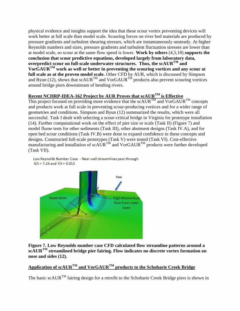
physical evidence and insights support the idea that these scour vortex preventing devices willwork better at full scale than model scale. Scouring forces on river bed materials are produced bypressure gradients and turbulent shearing stresses, which are instantaneously unsteady. At higherReynolds numbers and sizes, pressure gradients and turbulent fluctuation stresses are lower thanat model scale, so scour at the same flow speed is lower. Work by others (4,5,18) supports theconclusion that scour predictive equations, developed largely from laboratory data,overpredict scour on full-scale underwater structures. Thus, the scAURTM andVorGAURTM work as well or better in preventing the scouring vortices and any scour atfull scale as at the proven model scale. Other CFD by AUR, which is discussed by Simpsonand Byun (12), shows that scAURTM and VorGAURTM products also prevent scouring vorticesaround bridge piers downstream of bending rivers.
Recent NCHRP-IDEA-162 Project by AUR Proves that scAURTM is EffectiveThis project focused on providing more evidence that the scAURTM and VorGAURTM conceptsand products work at full scale in preventing scour-producing vortices and for a wider range ofgeometries and conditions. Simpson and Byun (12) summarized the results, which were allsuccessful. Task I dealt with selecting a scour-critical bridge in Virginia for prototype installation(14). Further computational work on the effect of pier size or scale (Task II) (Figure 7) andmodel flume tests for other sediments (Task III), other abutment designs (Task IV.A), and foropen bed scour conditions (Task IV.B) were done to expand confidence in these concepts anddesigns. Constructed full-scale prototypes (Task V) were tested (Task VI). Cost-effectivemanufacturing and installation of scAURTM and VorGAURTM products were further developed(Task VII).
Figure 7. Low Reynolds number case CFD calculated flow streamline patterns around ascAURTM streamlined bridge pier fairing. Flow indicates no discrete vortex formation onnose and sides (12).
Application of scAURTM and VorGAURTM products to the Schoharie Creek Bridge
The basic scAURTM fairing design for a retrofit to the Schoharie Creek Bridge piers is shown in

Figure 8. The ramp portion and vortex generators (Figure 9) add protection of the exposed sidesof the pier by bringing soil and rocks toward the pier. Figure 10 shows example stainless steelconstruction of the scAURTM. Because the Schoharie Creek Bridge pier is 19 feet wide, a newproprietary transition section has been developed that fits between a 9 foot wide leading edgeramp portion and fairing nose (Figure 9) and the maximum pier width. As discussed below withthe Costs, had this design been implemented before 1987, there would have no bridge failure dueto scour.
Figure 8. Flow from left to right. Drawing of a full-scale sheet metal scAURTM retrofitfairing with VorGAURTM for a pier (6) with piece-wise continuous concave-convexcurvature surfaces, with individual sections or pieces of nose surface (1); for the side of thepier (2); and the stern or tail, with individual sections or pieces of surface (4). The leadingedge ramp (7) and pier foundation protecting VGs (3) are mounted on leading edge plateand (3) mounted on (1) and (2) protect the foundation from open-bed scour.

1
Figure 9. Illustration of a VorGAURTM vortex generator at left upstream ramp (7) cornerthat creates a CCW vortex that brings open-bed scour gravel toward the foundation.
Figure 10. Example stainless steel scAURTM retrofit (black) for a pier. VorGAURTM vortexgenerators create CW vortices that bring low-speed flow up to prevent scour.
Application of scAURTM and VorGAURTM products to the Loon Mountain AbutmentCollapse
Figure 11 shows a scAURTM with VorGAURTM design for a spill-through abutment that prevents

all of the scouring vortices shown in Figure 5b. Figure 12 shows a scAURTM with VorGAURTM
design for a wing-wall abutment. Had either of these designs been used with the originalconstruction of the Loon Mountain Bridge, the abutment would not have failed. Even after the2011 collapse of the abutment, these designs and protective bank technologies could have beenused to repair the bridge and prevent bank erosion, rather than incur the cost of a new bridge.
Figure 11. Drawing of full-scale sheet metal scAURTM retrofit fairing with VorGAURTM fora spill-through abutment (6C) with piece-wise continuous concave-convex curvaturesurfaces consisting of individual sections or pieces of surface (1P), (1Q), (1R), (2C), (4P),(4Q), and (4R) within definable tolerances that produce the same effects as continuousconcave-convex-curvature surfaces. Vortex generators (3A) reduce the flow separation andfree-surface vortex effects while VG (3B) mounted on leading edge horizontal plate (7D1)connected to vertical plate (7D2) and VG (3C) protect the foundation from open-bed scour.Patent drawing (US Patent 9453319).

Figure 12. Drawing of full-scale sheet metal scAURTM retrofit fairing with VorGAURTM fora wing-wall abutment (6B) with piece-wise continuous concave-convex curvature surfacesconsisting of individual sections or pieces of surface (1L), (1M), (1N), (1O), (2B), (4M),(4N), and (4O) within definable tolerances that produce the same effects as continuousconcave-convex-curvature surfaces. Vortex generators (3A) reduce the flow separation andfree-surface vortex effects while VG (3B) on leading edge horizontal plate (7C1) that isconnected to vertical plate (7C2) and VG (3C) protect the foundation from open-bed scour.Patent drawing (US Patent 9453319).
Cost of the Bridge Failures and Cost-effective Manufacturing and Installation of scAURTM
and VorGAURTM Products
Before the AUR NCHRP project, AUR performed a cost-benefit analysis of scAURTM withVorGAURTM as compared to current scour countermeasures (14). Published information showsthat current expenses are required for scour monitoring, evaluation, and anti-scour mitigationdesign and construction, usually with rip-rap. For a bridge closed due to scour, the cost tomotorists due to traffic detours is estimated to be as great as all other costs combined, but werenot included in the analysis (14).
There is no situation where scAURTM and VorGAURTM products cost more than currentcountermeasures, as shown in Figure 13 for stainless steel retrofits. There is no situation whereany type of scour is worse with the use of the scAURTM and VorGAURTM products than withoutthem. The more frequent that scouring floods occur, the more cost effective are scAURTM andVorGAURTM. Clearly, scAURTM and VorGAURTM products are practical and cost-effective forUS highway bridges (14).
In order to further reduce costs and increase the versatility of the scAURTM and VorGAURTM

products, multiple manufacturing alternatives were considered. The required labor, materials,time, logistics, and practical issues were examined and used to evaluate manufacturingalternatives (14). Since the NCHRP-IDEA-162 project, detailed full-scale cost-effective versionshave been developed for installation. An installed welded stainless steel (SS) scAURTM retrofitbridge fairing is cost-effective, being about half of all costs for precast or cast-in-place concretemanufacturing and installation (14). Its corrosion resistance gives it a lifetime of 100 years evenin seawater environments, using a proper thickness, construction methods, and type of SS. It isan effective way to reduce weight and the cost associated with casting custom reinforcedconcrete structures. Another benefit is that the SS VorGAURTM vortex generators can be weldeddirectly onto the side sections instead of having to be integrated into the rebar cage of thereinforced concrete structure. Even for bridges with little life left, current temporarycountermeasures are much more expensive when the present value of future expenses isconsidered (14).
Figure 13. Economics of stainless steel retrofits.
Compared to component fabrication, there are significantly more uncertainties and assumptionsfor installation cost estimates. Location, accessibility, labor availability, material availability, andwater level are all relevant issues that affect the cost. Contractor bids will be the best way ofultimately determining the cost. For new construction, the estimates are done on the basis ofadded cost. This means the incremental increase in the total cost of the bridge project that can beattributed to scAURTM since laborers, contractors, and equipment are already involved in newconstruction. If a cofferdam is required or other site conditions produce extra costs, it affects the

project as a whole and not just scAURTM installation.
For the Schoharie Creek Bridge collapse, the estimated cost of the disaster and for recovery wasat least $45M, as mentioned above. Of the $42M in civil lawsuits, at least $10M was awarded.For the bridge pier shown in Figure 3, it would cost today about $250K for installation of astainless steel retrofit scAURTM with VorGAURTM for one pier under dry weather conditions.Given about a factor of 2 inflation factor since 1987, this would have been about $125K in 1987.Thus, for about $250K in 1987 or 0.45% of what was eventually spent, both piers could havebeen protected permanently from scouring vortices for all water flow speeds.
For the Loon Mountain Bridge abutment collapse, about $8M was spent on temporary repairsand a new replacement bridge. For either the spill-through (Figure 11) or wing-wall (Figure 12)abutment, it would have cost about $71K in 2011 to install stainless steel retrofit scAURTM withVorGAURTM components PRIOR to the collapse. Thus, for less than 0.9% of what was spentafter the abutment collapse, the abutment could have been permanently protected from scouringvortices for all water speeds.
Conclusions
Many bridges over water around the world are susceptible to scour of supporting rocks and soilduring peak flow events such as floods. Since scouring forces vary with the velocity-squared andscouring vortices are generated around piers and abutments, it is desirable to prevent thesevortices. This is what the scAURTM with VorGAURTM designs and components accomplish -prevent the formation of scouring vortices for all flow speeds.
Only 2 cases of bridge failures due to scour have been presented, but many others could havebeen presented with similar conclusions. In every case, expenditure of a small amount prior tothe failure would have saved 100 times or more funds for a recovery. This, of course, does notinclude the loss of life that may occur by the failure.
Designs for various types of piers, footings, abutments, angles of attack, river swirl, and bedconditions have been tested at model scale and some at full scale and show no scouring vortices(12, 14). Computational fluid dynamic studies show that no scouring vortices are produced.Other advantages of these designs are: much lower present value of all costs, lower river levelsand flow blockage, lower possibility for debris and ice buildup, and greater protection of piersand abutments against impact loads.
References
1. Lagasse, P., Zevenbergen, L., Schall, J., and Clopper, P., Bridge Scour and Stream InstabilityCountermeasures. FHWA Technical Report Hydraulic Engineering Circular (HEC)-23, 2001.2. Flint, M. M., Fringer, O.,Billington, S.L., Freyberg,D., and Diffenbaugh, N. S., 2017
Historical Analysis of Hydraulic Bridge Collapses in the Continental United States, ASCEJournal of Infrastructure Systems, 2017, 23(3),ASCE, ISSN 1076-0342.3. Lin, C., Han, J., Bennett, C., and Parsons, R., Case History Analysis of Bridge Failures due toScour, Climatic Effects on Pavement and Geotechnical Infrastructure, pp. 204 - 216,ASCE,

2013.4. Ettema, R., Yoon, Byungman, Nakato, Tatsuaki and Muste, Marian, A review of scourconditions and scour-estimation difficulties for bridge abutments, KSCE Journal of CivilEngineering, Volume 8, Number 6, Pages 643-65, 2004.5. Sheppard, D.M., Demir, H., and Melville, B., Scour at Wide Piers and Long Skewed Piers,NCHRP-Report 682, 2011.6. Tian, Q.Q., Simpson, R.L., and Lowe, K.T., A laser-based optical approach for measuringscour depth around hydraulic structures, 5th International Conference on Scour and Erosion,ASCE, San Francisco, Nov. 7-11, 2010.7. Baker, V.R., Kochel, R. C., and Patton, P.C. editors, Flood Geomorphology, Wiley-Interscience, 503 pages, 1988; p. 5.8. https://dailygazette.com/article/2017/04/04/thruway-bridge-collapse-of-1987-it-sounded-like-a-bomb-going-off.9. NTSB, Collapse of New York Thruway (I-90) Bridge over the SchoharieCreek, Near Amsterdam, New York, April 5, 1987, Highway Accident Report No.NTSB/HAR-88/02, National Transportation Safety Board, Washington, DC, 1988.10. https://www.upi.com/Archives/1988/04/02/Bridge-collapse-leaves-years-legacy-of-cost-pain/11. http://www.firsttracksonline.com/2011/10/02/work-progresses-to-replace-loon-mountain-bridge-washed out-by-flood/12. Simpson, R. L. and Byun, G., Low-Cost Scour Preventing Fairings for Bridges, paper IBC17-89, 34th International Bridge Conference, Gaylord National Resort, National Harbor, MD,June 5-8, 2017.13. Barkdoll, B.D., Ettema, R., and B. W. Melville, Countermeasures to Protect BridgeAbutments from Scour, NCHRP Report 587, 2007.14. Simpson, R. L., Unabridged Report on Full-Scale Prototype Testing and Manufacturingand Installation Plans for New Scour-Vortex-Prevention scAURTM and VorGAURTM Productsfor a Representative Scour-critical Bridge, AUR, Inc., Internal Report NCHRP-162, July 2013.15. Simpson, R.L. Turbulent Boundary Layer Separation, Annual Review of Fluid Mechanics,Vol. 21, pp.205-234, 1989.16. Simpson, R.L., Aspects of Turbulent Boundary Layer Separation, Progress in AerospaceSciences, Vol.32, pp.457 – 521, 1996.17. Simpson, R. L., Junction Flows, Annual Review of Fluid Mechanics, Vol. 33, pp. 415-443,2001.18. Sheppard, D.M., Odeh,M., Glasser,T., Large Scale Clear-Water Local Pier ScourExperiments, J. Hydraulic Eng., ASCE., Vol. 130, pp. 957 -063, 2004.