Embed Size (px)
Citation preview
TITLE 35: ENVIRONMENTAL PROTECTION
SUBTITLE C: WATER POLLUTION
CHAPTER II: ENVIRONMENTAL PROTECTION AGENCY
PART 370 ILLINOIS RECOMMENDED STANDARDS FOR SEWAGE WORKS
SUBPART A: INTRODUCTION
Section370.100 Purpose370.110 Scope and Applicability370.115 Incorporations by Reference
SUBPART B: ENGINEERING REPORTS, PLANS AND SPECIFICATIONS
Section370.200 General370.210 Engineering Report370.211 Design Flows370.220 Detailed Engineering Plan Drawings Format370.230 Specifications to Accompany Detailed Engineering Plan Drawings370.240 Revisions to Approved Plans and Specifications370.250 Operation During Construction370.260 Engineers Seal
SUBPART C: DESIGN OF SEWERS
Section370.300 General Considerations370.310 Design Basis370.320 Details of Design and Construction370.330 Manholes370.340 Sewers in Relation to Streams370.350 Protection of Water Supplies
SUBPART D: SEWAGE PUMPING STATIONS
Section
370.400 General370.410 Design370.420 Suction-Lift Pump Stations370.430 Submersible Pump Stations - Special Considerations370.440 Alarm Systems370.450 Emergency Operation370.460 Instructions and Equipment370.470 Force Mains
SUBPART E: SEWAGE TREATMENT WORKSSection370.500 Plant Location370.510 Quality of Effluent370.520 Design370.530 Plant Details370.540 Plant Outfalls370.550 Essential Facilities370.560 Safety370.570 Laboratory
SUBPART F: PRELIMINARY TREATMENT
Section370.600 General Considerations370.610 Screening Devices370.620 Grit Removal Facilities370.630 Pre-Aeration
SUBPART G: SETTLING
Section370.700 General Considerations370.710 Design Considerations370.720 Sludge and Scum Removal370.730 Protection and Service Facilities370.740 Imhoff Tanks370.750 Septic Tank - Tile System
SUBPART H: SLUDGE PROCESSING, STORAGE AND DISPOSAL
Section370.800 General370.810 Process Selection

370.820 Sludge Thickening370.830 Anaerobic Sludge Digestion370.840 Aerobic Sludge Digestion370.845 High pH Stabilization370.850 Sludge Pumps and Piping370.860 Sludge Dewatering370.870 Sludge Storage and Disposal
SUBPART I: BIOLOGICAL TREATMENT
Section370.900 Trickling Filters370.910 Rotating Biological Contactors (Repealed)370.915 Rotating Biological Contactors370.920 Activated Sludge370.930 Waste Stabilization Ponds and Aerated Lagoons370.940 Intermittent Sand Filtration for Secondary Treatment
SUBPART J: DISINFECTION
Section370.1000 General370.1010 Disinfection Process Selection370.1020 Chlorine Disinfection370.1021 Dechlorination370.1022 Ultraviolet Disinfection370.1030 Chlorine Gas Supply (Repealed)370.1040 Piping and Connections (Repealed)370.1050 Housing (Repealed)370.1060 Respiratory Protection Equipment (Repealed)370.1070 Application of Chlorine (Repealed)370.1080 Sampling and Testing
SUBPART K: TERTIARY FILTRATION
Section370.1100 Applicability370.1110 Type370.1120 High Rate Filtration370.1130 Low Rate Intermittent or Periodically Dosed Sand Filters
SUBPART L: NUTRIENT REMOVAL

Section370.1200 Phosphorus Removal by Chemical Treatment370.1210 Ammonia Control
APPENDIX A Table No. 1 - Resident Occupancy CriteriaAPPENDIX B Table No. 2 - Commonly Used Quantities of Sewage Flows From Miscellaneous Type FacilitiesAPPENDIX C Table No. 3 - Air Test Table for Sanitary Sewer Leakage Testing*APPENDIX D Figure No. 1 - Design of Sewers - Ratio of Peak Flow to Daily Average FlowAPPENDIX E Figure No. 2 - Primary SettlingAPPENDIX F Figure No. 3 - B.O.D. Removal Single Stage Trickling Filter Units Including Post Settling - No Recirculation IncludedAPPENDIX G Figure No. 4 - Break Tank Sketch for Potable Water Supply ProtectionAPPENDIX H Old Section Numbers Referenced (Repealed)
AUTHORITY: Implementing Sections 4 and 39 and authorized by Section 39 ofthe Environmental Protection Act [415 ILCS 5/4 and 39].
SOURCE: Adopted at 4 Ill. Reg. 14, p. 224, effective March 31, 1980;codified at 8 Ill. Reg. 19430; recodified at 18 Ill. Reg. 6375; amended at21 Ill. Reg. 12444, effective August 28, 1997.
NOTE: In this Part, superscript numbers or letters are denoted byparentheses; subscript are denoted by brackets.
SUBPART A: INTRODUCTION
<BSection 370.100 Purpose>>
The purpose of this Part is to establish criteria for the design andpreparation of plans and specifications for wastewater collection andtreatment systems.
(Source: Amended at 21 Ill. Reg. 12444, effective August 28, 1997)
<BSection 370.110 Scope and Applicability>>
a) These design criteria apply to conventional design concepts for wastewater collection and treatment systems. Where
non-conventional concepts or approaches to collection and treatment, particularly for very small systems, are being considered, the Agency should be contacted for any design guidance that may be available. b) In evaluating plans and specifications for new processes, the Agency will consider the specific information submitted with the design in accordance with the provisions of Section 370.520(b) for situations involving new process evaluation. c) These criteria are intended to establish limiting values for those aspects of plans and specifications which the Agency evaluates and to promote, as far as practicable, uniformity of practice throughout the State. For projects with a design flow average of over 100 million gallons per day (mgd), the application of specific design parameters in these criteria should be evaluated on a unit-by-unit basis to insure optimum design performance and cost effective construction. In applying these criteria, consideration must be given to the characteristics (including current water quality) and uses of the receiving stream in order to insure compliance with the applicable regulations of the Illinois Pollution Control Board (hereinafter "IPCB"). Users should also be cognizant of Federal requirements. d) The word "shall" is used where practice is sufficiently standardized to warrant compliance with specific requirements, or where safeguarding the public health or protecting water quality justifies such definite action. Words such as "should", "recommended" or "preferred" indicate desirable procedures or methods with deviations subject to individual project consideration. e) Definitions of terms and their use are intended to be in accordance with the GLOSSARY - WATER AND WASTEWATER CONTROL ENGINEERING, jointly prepared by the American Public Health Association (APHA), American Water Works Association (AWWA), American Society of Civil Engineers (ASCE), and Water Environment Federation (WEF). The units of expression are in accordance with the WEF Manual of Practice Number 6, Units of Expression for Wastewater Treatment.
(Source: Added at 21 Ill. Reg. 12444, effective August 28, 1997)<BSection 370.115 Incoporations by Reference>>
a) The following materials are incorporated by reference: 1) "Glossary: Water and Wastewater Control Engineering", Joint Editorial Board of the American Public Health Association,
American Society of Civil Engineers, American Wasteworks Association, American Pollution Control Federation (1969). 2) ASTM Standards - American Society for Testing and Materials, 100 Bar Harbor Drive, West Conshohoken PA:
ASTM C12-95 -- "Standard Practice for Installing Vitrified Clay Pipe Lines", Vol. 04.05, Chemical Resistant Materials, Vitrified Clay, Concrete, Fiber-Cement Products; Mortars; Masonry (1996).
ASTM C969-94 -- "Standard Practice for Infiltration and Exfiltration Acceptance Testing of Installed Precast Concrete Pipe Sewer Lines", Vol. 04.05, Chemical Resistant Materials, Vitrified Clay, Concrete, Fiber-Cement Products; Mortars; Masonry (1996).
ASTM C124 -- "Standard Test Method for Concrete Sewer Manholes by the Negative Pressure (Vacuum) Test", Vol. 04.05, Chemical Resistant Materials, Vitrified Clay, Concrete, Fiber-Cement Products; Mortars; Masonry (1996).
ASTM D2321 -- "Standard Practice for Underground Installation of Themoplastic Pipe for Sewers and Other Gravity-Flow Applications", Vol. 08.04, Plastic Pipe and Building Products (1996). 3) "AWWA Standard for Installation of Ductile-Iron Mains and their Appurtenances", ANSI/AWWA C600-93 (1994) American Wasteworks Association, 6666 Quincy Avenue, Denver CO 80235. 4) "National Electrical Code Handbook", 7th ed. (1996), National Fire Protection Association, 1 Batterymarch Park, P.O. Box 9101, Quincy MA 02269-9101. 5) "Standard Specifications for Water and Sewer Main Construction in Illinois", 5th ed. (1996), Illinois Society of Professional Engineers, Illinois Municipal League, the Association General Contractors of Illinois, Underground Contractors Association. 6) "Standard Specifications for Road and Bridge Construction" (1997), Illinois Department of Transportation. 7) Manuals of Practice, Joint Task Force of the Water Environment Federation (WEF) (formerly Water Pollution Control Federation), 601 Wythe Street, Alexandria VA 22314-1994 and the American Society of Civil Engineers (ASCE), 345 East 47th Street, New York NY 10017-2398:

"Gravity Sanitary Sewer Design and Construction", WPCF Manual of Practice (MOP) No. FD-5 (1982).
"Units of Expression for Wastewater Management", WEF Manual of Practice (MOP) No. 6 (1982). "Design of Municipal Wastewater Treatment Plants", vol. 1, WEF Manual of Practice (MOP) No. 8 (1992). b) The incorporations cited in this Section include no further editions or amendments.
(Source: Added at 21 Ill. Reg. 12444, effective August 28, 1997)
SUBPART B: ENGINEERING REPORTS, PLANS AND SPECIFICATIONS
<BSection 370.200 General>>
The criteria in this Subpart B are intended to be the technical basis forthe preparation of the engineering reports and plans and specifications forwaste collection and treatment works. For project planning requirements,applicable State and Federal guidance, regulations and statutes shall beconsulted. a) Grant Projects For projects that will be funded by Stateor Federal grants, applicable regulations, policy and guidance documents will govern the non-technical requirements and shall be used in the facility planning process. b) Non Grant Projects For those projects which are not covered by applicable State or Federal project planning requirements or for those other projects in which there is no project planning guidance in the applicable State or Federal regulations or statutes, the project planning guidance set forth in Section 370.112 shall be utilized.
(Source: Amended at 21 Ill. Reg. 12444, effective August 28, 1997)
<BSection 370.210 Engineering Report>>
a) General 1) The engineering report assembles basic information; presents design criteria and assumptions; examines alternate projects including preliminary layouts and cost estimates; describes

financing methods, user charges and operation and maintenance costs; reviews organizational and staffing requirements; offers a conclusion with a proposed project for client consideration; and outlines official actions and procedures to implement the project. 2) The concept, factual data and controlling assumptions and considerations for the functional planning of sewerage facilities are presented for each process unit and for the whole system. These data form the continuing technical basis for the detailed design and preparation of construction plans and specifications. 3) Architectural, structural, mechanical and electrical designs are usually excluded. Sketches may be used to aid in presentation of a project. Outline specifications of process units, special equipment, etc., may be included. 4) Engineering reports are not required for sewer extensions or sewer connections, but shall be required for the following projects: A) New treatment plants. B) Expansion or major modification of existing plants. C) New collection systems. D) Major upgrading of existing collection systems. b) Content The engineering report shall: 1) Prescribe design period and projected population. 2) Describe the specific service area for immediate consideration and indicate possible extensions and ultimate use. 3) Present data and information on anticipated quantities of flow and wastewater constituents. Data from comparable existing installations may be used to develop the design basis of the proposed facilities if data for the project under design cannot be obtained in accordance with procedures set forth in Subparts C, D and E of these standards. 4) Specify the scope and nature of collection system including pump stations and force mains for immediate and ultimate service areas. 5) Discuss various treatment alternatives with reference to optimum treatability and other relevant factors. 6) Develop a detailed basis of design for the recommended treatment process. 7) Indicate compliance with applicable effluent limitations and discuss the impact of the project on receiving waters.
8) Indicate compliance with the requirements of the Illinois Groundwater Protection Act [415 ILCS 55].
(Source: Amended at 21 Ill. Reg. 12444, effective August 28, 1997)
<BSection 370.211 Design Flows>>
The following flows shall be identified in the basis of design for sewers,lift stations, sewage treatment plants, treatment units and otherwastewater handling facilities. a) Design Average Flow The design average flow is the average of the daily volumes to be received for a continuous 12-month period of the design year, expressed as a volume per unit of time. b) Design Maximum Flow The design maximum flow is the largest volume of flow to be received during a continuous 24-hour period, expressed as a volume per unit of time. c) Design Peak Hourly Flow The design peak hourly flow is the largest volume of flow to be received during a one hour period, expressed as a volume per unit of time. d) Design Peak Flow The design peak flow is the instantaneous maximum flowrate to be received. (Source: Added at 21 Ill. Reg. 12444, effective August 28, 1997)
<BSection 370.220 Detailed Engineering Plan Drawings Format>>
a) General Detail plans shall contain as necessary, the following: 1) Plan views. 2) Elevations. 3) Sections and supplementary views which, together with the specifications and general layouts, facilitate construction of the works. 4) Dimensions and relative elevations of structures. 5) Location and outline form of equipment. 6) Location and sizing of piping. 7) Water levels. 8) Ground elevations. 9) Location and identification of all private and public water supply wells (refer to Section 370.210(b)(8)), structures and
facilities (refer to Section 370.350(b)(1)(A)). 10) Descriptive notations as necessary for clarity. b) Plans of Sewers 1) General Plan Except as provided in subsection (b)(1)(C) below, a comprehensive plan of the existing and proposed sewers shall be submitted for projects involving new sewer systems or substantial additions to existing systems. This plan shall show the following: A) Geographical Features i) Topography and elevations: Existing or proposed streets and all streams or water surfaces shall be clearly shown. Contour lines at suitable intervals should be included. ii) Streams: The direction of flow in all streams, and high and low water elevations of all water surfaces at sewer outlets and overflows shall be shown. iii) Boundaries: The boundary lines of the municipality and the sewer district or area to be sewered shall be shown. B) Sewers The plan shall show the location, size and direction of flow of all existing and proposed sanitary and combined sewers draining to the treatment works concerned. C) Sewer Atlas The comprehensive plan of the existing sewers described above need not be submitted in each case if the system owner has furnished the Agency a copy of its sewer atlas showing the information required by subsection (b)(1). The project submittal, however, must include all the proposed work, and must be accompanied by a location map showing the proposed project and the route of the outlet sewer to the receiving plant, where necessary. 2) Detail Plans Detail plans shall be submitted. Profiles should have a horizontal scale of not more than 100 feet to the inch and a vertical scale of not more than 10 feet to the inch. Plan views should be drawn to a corresponding horizontal scale. Plans and profiles shall show: A) Location of streets and sewers. B) Line of ground surface, size, material and type of pipe, length between manholes, invert and surface elevation at each manhole, and grade of sewer between each two
adjacent manholes. All manholes shall be numbered on the plan and correspondingly numbered on the profile. C) Except where overhead sewers are required by local ordinance, if there is any question of the sewer being sufficiently deep to serve any residence, the elevation and location of the basement floor shall be plotted on the profile of the sewer which is to serve the house in question. The engineer shall state that all sewers are sufficiently deep to serve adjacent basements except where otherwise noted on the plans. D) Locations of all special features such as inverted siphons, concrete encasements, elevated sewers, etc. E) All known existing structures both above and below ground which might interfere with the proposed construction, particularly water mains, gas mains, storm drains, etc. F) Special detail drawings, made to a scale to clearly show the nature of the design, shall be furnished to show the following particulars: i) All stream crossings and sewer outlets, with elevations of the stream bed and of normal and extreme high and low water levels. ii) Cross sections and details of all special or non standard joints. iii) Details of all sewer appurtenances such as manholes, lampholes, inspection chambers, inverted siphons, regulators, tide gates and elevated sewers. c) Plans of Sewage Pumping Stations 1) Location Plan A plan shall be submitted for projects involving construction or revision of pumping stations. This plan shall show the following: A) The location and extent of the tributary area. B) Any municipal boundaries within the tributary area. C) The location of the pumping station and force main. 2) Detail Plan Detail plans shall be submitted showing the following where applicable: A) Grading plan of the station site. B) Location of existing pumping station. C) Proposed pumping station, including provisions for installation of future pumps or ejectors.
D) Elevation of high flood water at the site, and maximum elevation of sewage in the collection system upon occasion of power failure, and the pumping station elevations. E) Test borings and groundwater elevations. F) Force main routing and profile. d) Plans of Sewage Treatment Plants 1) Location Plan A) A plan shall be submitted showing the sewage treatment plant in relation to the remainder of the system. B) Sufficient topographic features shall be included to indicate its location with relation to streams and the point of discharge of treated effluent. C) All residences within one-half mile of the site shall be shown. 2) General Layout Layouts of the proposed sewage treatment plant shall be submitted, showing: A) Topography of the site. B) Size and location of plant structures. C) Schematic flow diagram showing the flow through various plant units. D) Piping, including any arrangements for by-passing individual units. Materials handled and direction of flow through pipes shall be shown. E) Test borings and expected range of ground water elevations. 3) Detail Plans Detail plans shall show the following: A) Location, dimensions and elevations of all existing and proposed plant facilities, including flood protection structures where applicable. B) Elevations of high and low water levels of the body of water to which the plant effluent is to be discharged. C) Type, size, pertinent features, and manufacturer's rated capacity of all pumps, blowers, motors and other mechanical devices. D) Hydraulic profiles of the treatment plant at design peak flow including recirculated flows at the 25-year flood elevation in the receiving watercourse. To ensure their proper functioning, the hydraulic profile at measuring devices at minimum flow shall be shown. E) Hydraulic profiles shall be shown for supernatant liquor
lines, recirculating flow piping and sludge transfer lines at the design peak flows carried by each system. F) Adequate description of any features not otherwise covered by specifications or engineer's report.
(Source: Amended at 21 Ill. Reg. 12444, effective August 28, 1997)
<BSection 370.230 Specifications to Accompany Detailed Engineering PlanDrawings>>
a) Complete technical specifications for the construction of sewers, sewage pumping stations, sewage treatment plants, and all appurtenances, shall accompany the plans. b) The specifications accompanying construction drawings shall include, but not be limited to, the following: 1) All construction information, not shown on the drawings, which is necessary to inform the builder in detail of the design requirements as to the quality of materials and workmanship and fabrication of the project. 2) The type, size, strength, operating characteristics and rating of equipment. 3) Allowable infiltration. 4) The complete requirements for all mechanical and electrical equipment, including machinery, valves, piping and jointing of pipe. 5) Electrical apparatus, wiring and meters. 6) Laboratory fixtures and equipment. 7) Operating tools. 8) Construction materials. 9) Special filter materials such as stone, sand, gravel or slag. 10) Chemicals when used. 11) Miscellaneous appurtenances. 12) Instruction for testing materials and equipment as necessary. 13) Availability of soil boring information.
(Source: Amended at 21 Ill. Reg. 12444, effective August 28, 1997)
<BSection 370.240 Revisions to Approved Plans and Specifications>>
a) Any deviations from approved plans or specifications for structural configuration, appurtenances or manufactured equipment, affecting capacity, flow, operation of units or operational safety, and for substitution of the manufactured equipment
specified and depicted in the plan documents shall be approved in writing by the Agency before such installation of equipment or construction changes are made. b) Plans and specifications requiring Agency approval under subsection (a) should be submitted well in advance of the ordering and delivery of equipment or any construction work which will be affected by such changes, to allow sufficient time for review and approval. Record drawings of the project as completed shall be submitted to the Agency.
<BSection 370.250 Operation During Construction>>
Specifications shall contain a time schedule describing the plant andcollection system operational modes during construction. Where unitsessential to effluent quality are involved, temporary measures, such as wethauling, sludge storage lagoons and portable pumping facilities shall beincluded in the specifications so as to ensure continuity of operation asrequired and approved by the Agency.
(Source: Amended at 21 Ill. Reg. 12444, effective August 28, 1997)<BSection 370.260 Engineers Seal>>
Plans and specifications, prepared by an Illinois Registered ProfessionalEngineer when required by Section 14 of the Illinois ProfessionalEngineering Act [225 ILCS 325/14], fully describing the design, nature,function and interrelationship of each individual component of the facilityor source, shall be submitted, except that the Agency may waive thisrequirement for plans and specifications when the application is for aroutine renewal.
(Source: Amended at 21 Ill. Reg. 12444, effective August 28, 1997)
SUBPART C: DESIGN OF SEWERS
<BSection 370.300 General Considerations>>
a) Type of Sewers The Agency will approve plans for new sewer systems and extensions only when designed as the separate sanitary type in which precipitation runoff and ground water from foundation drains are excluded. The Agency will not approve the installation of new combined sewers, except as provided in 35 Ill. Adm. Code 306.302.
b) Design Period Sewer systems should be designed for the estimated ultimate tributary population, except in considering parts of the systems that can be readily increased in capacity. Similarly, consideration should be given to the maximum anticipated capacity of institutions, industrial parks, etc. c) Design Factors In determining the required capacities of sanitary sewers, the following factors should be considered: 1) Design peak flow. 2) Additional design peak flow from industrial plants. 3) Ground water infiltration. 4) Topography of area. 5) Location of waste treatment plant. 6) Depth of excavation. 7) Pumping requirements.
(Source: Amended at 21 Ill. Reg. 12444, effective August 28, 1997)
<BSection 370.310 Design Basis>>
a) Per Capita Flow 1) New Sewers for Undeveloped Areas New sewer systems to serve currently undeveloped areas shall be designed on the basis of a design average flow of not less than 100 gallons per capita per day which is assumed to cover normal infiltration, but an additional allowance should be made where conditions are unfavorable. 2) New Sewers for Existing Developed Areas For new sewers designed to serve existing developed areas, the design average flow per capita (100 gpd) shall be appropriately increased to allow for inflow/infiltration contributions from the existing buildings other than roof and foundation drains which shall be excluded in accordance with Section 370.121(a). b) Design Peak Flow 1) The design peak flow for sanitary sewers shall be selected based on one of the following methods: A) The ratio of peak to average daily flow as determined from Appendix D, Figure No. 1. B) Values established from an infiltration/inflow study acceptable to the Agency. 2) Use of other values for the design peak flow will be
considered if justified on the basis of extensive documentation. 3) Combined Sewer Interceptors Intercepting sewers, in the case of combined sewer systems, should fulfill the above requirements for sewers and have sufficient additional capacity to transport the increment of combined sewage required by the IPCB Regulations. c) Alternate Methods When deviations from subsections (a) and (b) are proposed, a description of the procedure used for sewer design shall be included in the submission of plan documents. d) Basis of Design and Calculations The basis of design for all sewer projects shall accompany the plan documents. Calculations shall be submitted to show that sewers will have sufficient hydraulic capacity to transport the design peak flows.
(Source: Amended at 21 Ill. Reg. 12444, effective August 28, 1997)
<BSection 370.320 Details of Design and Construction>>
a) Minimum Size No public gravity sewer conveying raw sewage shall be less than 8 inches in diameter. b) Depth Sewers shall be sufficiently deep to prevent freezing. Sewers should be sufficiently deep to serve basements except where overhead sewers are required by local ordinances or will be provided. 1) Minimum Cover The minimum cover of sewers shall be no less than 3 feet unless special structural protection is provided. 2) Buoyancy Where high ground water conditions are anticipated, buoyancy of sewers shall be considered and, if necessary, adequate provisions should be made for protection. c) Slope 1) All sewers shall be designed and constructed to give mean velocities, when flowing full, of not less than 2.0 feet per second, based on Manning's formula using an "n" value of 0.013. The following minimum slopes shall be provided; however, slopes greater than these are desirable:

Minimum Slope in Feet
Sewer Size Per 100 Feet Flow (mgd)
8 inch 0.40 0.49 10 inch 0.28 0.75 12 inch 0.22 1.07 14 inch 0.17 1.43 15 inch 0.15 1.61 16 inch 0.14 1.85 18 inch 0.12 2.35 21 inch 0.10 3.23 24 inch 0.08 4.13 27 inch 0.067 5.17 30 inch 0.058 6.37 33 inch 0.050 7.66 36 inch 0.046 9.23 42 inch 0.036 12.41
2) Under special conditions, if detailed justifiable reasons are given, slopes slightly less than those required for the 2.0 feet per second velocity when flowing full may be permitted. Such decreased slopes will only be considered where the depth of flow will be 0.3 of the diameter or greater for design average flow. Whenever such decreased slopes are selected, the design engineer must furnish with his report his computations of the depths of flow in such pipes at minimum, design average, and design peak rates of flow. It must be recognized that decreased slopes may cause additional sewer maintenance expense and special linings or materials should be considered for corrosion protection. 3) Uniform Slope Sewers shall be laid with uniform slope between manholes. 4) Steep Slope Protection Sewers on 20 percent slope or greater shall be anchored securely with concrete anchors or equal, spaced as follows: A) Not over 36 feet center to center on grades 20 percent and up to 35 percent. B) Not over 24 feet center to center on grades 35 percent and up to 50 percent. C) Not over 16 feet center to center on grades 50 percent and over. d) Alignments

1) Straight Alignments Except as noted in subsection (d)(2), all sewers shall be laid with straight alignments between manholes. 2) Curvilinear Alignments Curvilinear sewers are permitted in special cases provided the following minimum requirements are met: A) Curvilinear Sewers 24 Inches in Diameter and Smaller i) Location: Curvilinear alignments should follow the general alignment of streets. ii) Type Curve: Only simple curve design is acceptable. iii) Radius of Curvature: The minimum allowable radius of curvature is 300 feet. iv) Manholes: Manholes are required at the beginning and end of all curves. v) Joints: Compression joints are required. The ASTM or AWWA maximum allowable deflection of the pipe joints shall not be exceeded. vi) Velocity: In order to maintain a minimum velocity of 2 feet per second in curvilinear sewers, hydraulics of the curvilinear alignment shall be taken into account and the minimum slopes indicated in subsection (c)(1) must be increased accordingly. B) Curvilinear Sewers 24 Inches Through 48 Inches in Diameter Curvilinear sewers larger than 24 inches in diameter up to 48 inches in diameter constructed with pressure pipe meeting AWWA standards may be used. Other curvilinear sewers larger than 24 inches in diameter up to 48 inches in diameter shall meet the requirements of subsection (d)(2)(A) except that the joints must be manufactured so that they fit together squarely without deflection at the design curvature and the radius of curvature may be less than 300 feet. C) Curvilinear Sewers Larger Than 48 Inches in Diameter Curvilinear sewers larger than 48 inches in diameter shall be provided with square fitting compression joints and shall meet the requirements of subsection (d)(2)(A)(vi). The remaining design requirements under subsection (d)(2)(A) for these sewers will be reviewed by the Agency on a case by case basis. e) Increasing Size When a smaller sewer joins a larger one, the invert of the larger

sewer should be sufficiently lower to maintain the energy gradient. An approximate method for securing these results is to place the 0.8 depth point of both sewers at the same elevation. f) High Velocity Protection Where velocities greater than 15 feet per second are attained, the special provisions described in subsection (c)(4) shall be made to protect against displacement by erosion and shock. g) Materials and Installation 1) Materials A) Any generally accepted material for sewers will be given consideration, but the material selected should be suitable for local conditions, such as character of industrial wastes, possibility of septicity, soil characteristics, exceptionally heavy external loadings, abrasion, structural considerations and similar problems. B) All sewers shall be designed and installed to prevent damage from superimposed loads. Proper allowance for loads on the sewer shall be made because of the width and depth of trench. When the bearing strength of the pipe is not adequate to withstand the superimposed loading, other pipe material, special handling, concrete cradle or special construction shall be used. C) For new pipe materials for which ASTM standards have not been established (see subsection (g)(2)), the designing engineer shall provide complete installation specifications developed on the basis of criteria adequately documented and certified in writing by the pipe manufacturer to be satisfactory for the design conditions for the specific project. Such documentation and manufacturers' certification shall be submitted as a part of the project plan documents. 2) Installation A) Standards i) Installation specifications shall contain appropriate requirements based on the criteria, standards and requirements established by ASTM. Requirements shall be set forth in the specifications for the pipe and methods of bedding and backfilling thereof so as not to damage the pipe or its joints, impede cleaning operations and future tapping, nor create excessive side fill pressures or ovalation of the pipe, nor seriously
impair flow capacity. ii) For new pipe material, the installation specifications shall meet the provisions of subsection (g)(1). B) Trenching i) The width of the trench shall be ample to allow the pipe to be laid and jointed properly and to allow the backfill to be placed and compacted as needed. The trench sides shall be kept as nearly vertical as possible. When wider trenches are dug, appropriate bedding class and pipe strength shall be used. ii) Ledge rock, boulders, and large stones shall be removed to provide a minimum clearance of 4 inches below and on each side of all pipe and joints. C) Bedding i) Bedding classes A, B, or C, as described in ASTM Cl2-95, "Standard Practice for Installing Vitrified Clay Pipe Lines" (1996) or "Standard Specifications for Water and Sewer Main Construction in Illinois", 5th ed. (1996) (no later additions or amendments) or WPCF Manual of Practice (MOP) No. FD-5 (1982) (no later additions or amendments) shall be used for all rigid pipe provided the proper strength pipe is used with the specified bedding to support the anticipated load. ii) Bedding class I, II, or III, as described in ASTM D2321-89, "Standard Practice for Underground Installation of Thermoplastic Pipe for Sewers and Other Gravity-Flow Applications" (1996) (no later editions or amendments) or Standard Specifications for Water and Sewer Main Construction in Illinois, 5th ed. (1996) (no later additions or amendments), or WPCF MOP No. FD-5 (1982)(no later additions or amendments) shall be used for all flexible pipe provided the proper strength pipe is used with the specified bedding to support the anticipated load. D) Backfill i) Backfill shall be of a suitable material removed from excavation except where other material is specified. Debris, frozen material, large clods or stones, organic matter, or other unstable materials shall not be used for backfill within 2 feet of the
top of the pipe. ii) Backfill shall be placed in such a manner as not to disturb the alignment of the pipe. iii) For flexible pipe, as a minimum, backfill material shall be placed and carefully compacted in accordance with ASTM D2321-89 (1996) to provide the necessary support for the pipe. 3) Deflection Testing of Flexible Pipe. A) The design specifications shall provide that the first 1200 feet of sewer and at least 10% of the remainder of the sewer project shall be deflection tested. The entire length of a sewer of less than 1200 feet shall be deflection tested. B) If the deflection test is to be run using a rigid ball or mandrel, it shall have a diameter equal to 95% of the inside or base diameter of the pipe as established in the ASTM standard to which the pipe is manufactured. The test shall be performed without mechanical pulling devices. C) The individual lines to be tested shall be tested for final acceptance no sooner than 30 days after they have been installed. D) Whenever possible and practical, the testing shall initiate at the downstream lines and proceed towards the upstream lines. E) No pipe shall exceed a deflection of 5%. F) In the event that the deflection exceeds the 5% limit in 10% or more of the manhole intervals tested, the total sewer project shall be tested. h) Joints and Infiltration 1) Joints The type and method of making joints and the materials used shall be included in the specifications and also shall be shown on the plans. Sewer joints shall be specified to minimize infiltration and to prevent the entrance of roots. Joint material shall conform to ASTM standards. Cement grout joints shall not be used for pipe to pipe joints. 2) Leakage Testing Leakage tests shall be specified. A) Test Sections The design specifications shall provide that the first 1200 feet and at least 10% of the remainder of the sewer project shall be tested for leakage. The entire length
of a sewer of less than 1200 feet shall be tested for leakage. In the event that 10% or more of the manhole intervals tested do not pass the leakage test, the entire sewer project shall be tested. B) Testing Methods Testing methods may include appropriate water or low pressure air testing. The use of television cameras or other visual methods for inspection prior to placing the sewer in service and prior to acceptance is recommended. C) Water Testing i) The leakage outward or inward (exfiltration or infiltration) shall not exceed the following limits in gallons per inch of pipe diameter per mile per day for any section of the system: Exfiltration: 240 Infiltration: 200 ii) An exfiltration or infiltration test shall be performed with a minimum positive head of 2 feet. D) Air Testing If used, the air test shall, as a minimum, conform to the test procedure described in Section 31-1.11B of Standard Specifications for Water and Sewer Main Construction in Illinois, 5th ed. (1996)(no later additions or amendments). The specifications shall require that the time required for a pressure drop from 3.5 to 2.5 PSIG not be less than the time specified in the Air Test Table in Appendix C. The testing methods selected should take into consideration the range in groundwater elevations projected and the situation during the test. i) Service Connections Sewer service connections shall meet the same criteria as public sanitary sewers described elsewhere in this Subpart C except as noted in this subsection (i). Roof and foundation drain connections to the sewer service connection are prohibited except as provided for in 35 Ill. Adm. Code 306.302. The service connection tap into the public sewer shall be watertight and shall not protrude into the public sewer. If a saddle type connection is used, it shall be a commercially available device designed to join with the types of pipe that are to be connected. All materials used to make service connections shall be compatible with one another and with the pipe materials to be joined, and
shall be corrosion-proof. 1) Size Service sewers and fittings shall be a minimum of 4 inches in diameter, but shall not be less than the diameter of the plumbing pipe from the building. 2) Slope Service sewers shall have a minimum slope of 1%. 3) Alignment When straight line alignment is not maintained on service connections, cleanouts or manholes shall be provided at points of changes in alignment.
(Source: Amended at 21 Ill. Reg. 12444, effective August 28, 1997)
<BSection 370.330 Manholes>>
a) Location Except as noted in Section 370.123(d)(2), manholes shall be installed at the end of each line; at all changes in grade, size or alignment; at all sewer intersections; and at distances not greater than 400 feet for sewers 15 inches or less, and 500 feet for sewers 18 inches through 30 inches. Distances up to 600 feet may be approved in cases where adequate modern cleaning equipment for such spacing is provided. Greater spacing may be permitted in larger sewers and in those carrying a settled effluent. Lampholes may be used only for special conditions and shall not be substituted for manholes nor installed at the end of laterals greater than 150 feet in length. b) Type 1) Drop Type A pipe shall be provided for a sewer entering a manhole where its invert elevation is more than 24 inches above the manhole invert. If an inside drop pipe is used, the manhole diameter shall be large enough to provide a minimum clearance of 48 inches between the pipe and the opposite side of the manhole. Inside drip pipes shall be anchored to the manhole wall with corrosion-proof fasteners and bands. For sewers 36 inches in diameter or greater, the requirements for a drop pipe do not apply if the spring line of the incoming pipe is at or below the spring line of the main sewer. As a minimum, the diameter of the drop pipe shall be at least 2/3 as large as the diameter of the sewer tributary to the drop pipe. 2) Non Drop Type
Where the difference in elevation between the incoming sewer invert and the manhole invert is less than 24 inches, the manhole invert should be filleted to prevent solids deposition. c) Diameter 1) For sewers 36 inches in diameter and smaller, the minimum diameter of manholes shall be 48 inches. For sewers larger than 36 inches in diameter, the manhole diameter at the invert shall be sufficiently large to accommodate the incoming pipes; and the riser barrel diameter shall be a minimum of 48 inches. 2) A minimum access lid diameter of 24 inches shall be provided. d) Flow Channel The flow channel through manholes should be made to conform in shape and slope to that of the sewers. A bench shall be provided which should have a minimum slope of 2 inches per foot. e) Watertightness 1) Construction Requirements Watertight manhole covers shall be used wherever the manhole tops may be flooded by surface runoff or high water or are below cover. Pickholes shall not be larger than 1 inch in diameter or shall be of the concealed type. Construction lifting holes on manhole rings shall be plugged from the outside and the exterior and joints of the manhole elements shall be waterproofed. Precast inlet and outlet connections fitted with "0" rings or other equally watertight connections shall be provided. 2) Inspection The specifications shall include a requirement for inspection and leakage testing of all manholes for watertightness in accordance with ASTM C969-94--"Standard Practice for Infiltration and Exfiltration Acceptance Testing of Installed Precast Concrete Pipe Sewer Lines", Vol. 04.05, Chemical Resistant Materials, Vitrified Clay, Concrete, Fiber-Cement Products; Mortars; Masonry (1996) (no later editions or amendments) or ASTM C1244-93 "Standard Test Method for Concrete Sewer Manholes by the Negative Pressure (Vacuum) Test", Vol. 04.05, Chemical Resistant Materials, Vitrified Clay, Concrete, Fiber-Cement Products; Mortars; Masonry (1996) (no later editions or amendments) prior to placing into service.
(Source: Amended at 21 Ill. Reg. 12444, effective August 28, 1997)

<BSection 370.340 Sewers in Relation to Streams>>
a) Location of Sewers on Streams 1) Cover Depth A) The top of all sewers entering or crossing streams shall be at a sufficient depth below the natural bottom of the stream bed to protect the sewer line. In general the following cover requirements must be met: i) One foot of cover is required where the sewer is located in rock. ii) Three feet of cover is required in other material. In major streams, more than three feet of cover may be required. iii) In paved stream channels, the top of the sewer line should be placed below the bottom of the channel pavement. B) Less cover will be approved only if the proposed sewer crossing will not interfere with the future improvements to the stream channel. Reasons for requesting less cover should be given in the project proposal. 2) Horizontal Location Sewers located along streams shall be located outside of the stream bed and sufficiently removed therefrom to provide for future possible stream widening and to prevent pollution by siltation during construction. 3) Structures The sewer outfalls, headwalls, manholes, gate boxes, or other structures shall be located so they do not interfere with the free discharge of flood flows of the stream. 4) Alignment Sewers crossing streams should be designed to cross the stream as nearly perpendicular to the stream flow as possible and shall be designed without change in grade. Sewer systems shall be designed to minimize the number of stream crossings. b) Construction 1) Materials and Backfill A) Sewers entering or crossing streams shall be constructed of cast or ductile iron pipe with mechanical joints and shall be capable of absorbing pipe movement and joint-deflection while remaining intact and watertight. B) The backfill used in the trench shall be coarse
aggregate, gravel, or other materials which will not cause siltation, pipe damage during placement or chemical corrosion in place. 2) Siltation and Erosion Construction methods that will minimize siltation and erosion shall be employed. The design engineer shall include in the project specifications the methods to be employed in the construction of sewers in or near streams to provide adequate control of siltation and erosion. Specifications shall require that cleanup, grading, seeding, and planting or restoration of all work areas shall begin immediately. Exposed areas shall not remain unprotected for more than seven days. c) Aerial Crossings 1) Structural Support Support shall be provided for all joints in pipes utilized for aerial crossings. The supports shall be designed to prevent frost heave, overturning and settlement. 2) Freeze and Expansion Protection Protection against freezing shall be provided. This may be accomplished through the use of insulation and increased slope. Expansion jointing shall be provided between the aerial and buried sections of the sewer line. 3) Flood Clearance For aerial stream crossings, the impact of flood waters and debris shall be considered. The bottom of the pipe should be placed no lower than the elevation of the 50 year flood. d) Inverted Siphons Inverted siphons shall have not less than 2 barrels, with a minimum pipe size of 6 inches and shall be provided with necessary appurtenances for convenient flushing and maintenance. Long radius fittings should be used. The inlet and outlet structures shall have adequate clearances for rodding; and in general, sufficient head shall be provided and pipe sizes selected to secure velocities of at least 3.0 feet per second for design average flows. The inlet and outlet structures shall be designed so that the design average flow is diverted to 1 barrel, and so that either barrel may be cut out of service for cleaning. (Source: Amended at 21 Ill. Reg. 12444, effective August 28, 1997)
<BSection 370.350 Protection of Water Supplies>>
a) Water Supply Interconnections
There shall be no physical connections between a public or private potable water supply system and a sewer, or appurtenance thereto, which would permit the passage of any sewage or polluted water into the potable supply. b) Location Relative to Water Works Structures 1) Location and Soil Condition A) The engineering plan documents shall show the location of all existing water works structures (basins, wells, other treatment units, etc.) that are within 200 feet of the proposed sewer. B) Soil conditions in the vicinity of the water works structures shall be investigated and depicted on the plans. 2) Minimum Distances The following minimum distances apply to clay and loan soils and, as a minimum, shall be doubled for sand. In areas where creviced limestone or gravel may be encountered, the Agency shall be contacted for a determination as to what minimum separation distances and special construction will be required. A) Non-watertight sewers and sewer appurtenances such as manholes and wetwells shall not be located closer than 50 feet from water works structures. B) Sewers located closer than 50 feet to water works structures shall be constructed with water main quality pipe and joints that comply with 35 Ill. Adm. Code 653.119. All such pipe shall be pressure tested in accordance with "AWWA Standard for Installation of Ductile-Iron Water Mains and their Appurtenances," ANSI/AWWA C600-93 (1994), (no later editions or amendments) for a working pressure equal to or greater than the maximum possible surcharge head to assure watertightness prior to backfilling. No sewer shall be located closer than 10 feet from water works structures. c) Relation to Water Mains 1) Horizontal and Vertical Separation A) Whenever possible, a sewer must be at least ten feet horizontally from any existing or proposed water main. B) Should local conditions exist which would prevent a lateral separation of ten feet, a sewer may be closer than ten feet to a water main provided that the water main invert is at least eighteen inches above the crown of the sewer, and is either in a separate trench or in

the same trench on an undisturbed earth shelf located to one side of the sewer. C) If it is impossible to obtain proper horizontal and vertical separation as described above, both the water main and sewer must be constructed with water main quality pipe and joints that comply with 35 Ill. Adm. Code 653.119 and shall be pressure tested in accordance with "AWWA Standard for Installation of Ductile-Iron Water Mains and their Appurtenances," ANSI/AWWA C600-93 (1994) (no later editions or amendments) for a working pressure equal to or greater than the maximum possible surcharge head to assure watertightness before backfilling. 2) Water-Sewer Line Crossings A) Whenever possible, sewers crossing water mains shall be laid with the sewer below the water main with the crown of the sewer a minimum of 18 inches below the invert of the water main. The vertical separation shall be maintained on each side of the crossing until the perpendicular distance from the water main to the sewer is at least 10 feet. The crossing shall be arranged so that the sewer joints will be equidistant and as far as possible from the water main joints. Adequate support shall be provided for the water mains to prevent damage due to settling of the sewer trench. Refer to Appendix H, Drawing No. 1. B) Where a sewer crosses under a water main and it is not possible to provide an 18-inch vertical separation, the following special construction methods shall be specified (refer to Appendix H, Drawing No. 2): i) The sewer shall either be constructed with water main pipe and joints that comply with 35 Ill. Adm. Code 653.119 and shall be pressure tested in accordance with "AWWA Standard for Installation of Ductile-Iron Water Mains and their Appurtenances," ANSI/AWWA C600-93 (1994) (no later editions or amendments) for a working pressure equal to or greater than the maximum possible surcharge head or shall be encased in a carrier pipe with the ends sealed, that, along with the joints, complies with 35 Ill. Adm. Code 653.119. ii) The water main quality sewer or carrier pipe shall extend on each side of the crossing to a point
where the perpendicular distance from the water main to the sewer is at least 10 feet. iii) For the required length of the water main quality sewer or carrier pipe, omit the select granular cradle and granular backfill to one foot over the crown of the sewer and use selected excavated material (Class IV) and compact to 95% of Standard Proctor maximum density. iv) Point loads between the sewer or sewer casing and the water main are prohibited. v) Adequate support shall be provided for the water main to prevent damage due to settling of the sewer trench. C) Where it is not possible for a proposed sewer to cross under an existing water main, the specifications shall require the construction methods set out in subsection (c)(2)(B) above and shall require that any select granular backfill above the crown of the water main be removed within the width of the proposed sewer trench and be replaced with select excavated material (Class IV) compacted to 95% of Standard Proctor maximum density. Where a proposed sewer must cross over a proposed water main, an 18-inch vertical separation shall be maintained. Refer to Appendix H, Drawing No. 3. 3) Sewer Manhole Separation From Water Main No water pipe shall pass through or come into contact with any part of a sewer manhole.
(Source: Amended at 21 Ill. Reg. 12444, effective August 28, 1997)
SUBPART D: SEWAGE PUMPING STATIONS
<BSection 370.400 General>>
a) Flooding Sewage pumping station structures and electrical and mechanical equipment shall be protected from physical damage by the 100 year flood. Sewage pumping stations should remain fully operational and accessible during the 25 year flood. Regulations of State and Federal agencies regarding flood plain obstructions shall be considered.

b) Accessibility The pumping station shall be readily accessible by maintenance vehicles during all weather conditions. The facility should be located off the traffic way of streets and alleys. c) Grit Where it is necessary to pump sewage prior to grit removal, the design of the wet well and pump station piping shall receive special consideration to avoid operational problems from the accumulation of grit.
<BSection 370.410 Design>>
The following items should be given consideration in the design of sewagepumping stations: a) Type Sewage pumping stations in general use fall into three types: wet well/dry well, submersible, and suction lift. b) Structures 1) Separation Dry wells, including their superstructure, shall be completely separated from the wet well. Common walls must be gastight. 2) Pump Removal Provision shall be made to facilitate removing pumps and motors. 3) Access A) Suitable and safe means of access shall be provided to dry wells and to wet wells. Access to wet wells containing either bar screens or mechanical equipment requiring inspection or maintenance shall conform to Section 370.600(a)(2)(C). B) For built-in-place pump stations, a stairway to the dry well with rest landings shall be provided at vertical intervals not to exceed 12 feet. For factory-built pump stations over 15 feet deep, a rigidly fixed landing shall be provided at vertical intervals not to exceed 10 feet. Where a landing is used, a suitable and rigidly fixed barrier shall be provided to prevent an individual from falling past the intermediate landing to a lower level. A manlift or elevator may be used in lieu of landings in a factory-built station, provided emergency access is included in the design. 4) Buoyancy
Where high ground water conditions are anticipated, buoyancy of the sewage pumping station structures shall be considered and, if necessary, adequate provisions shall be made for protection. c) Pumps and Pneumatic Ejectors 1) Multiple Units Multiple pumps or ejector units shall be provided. Where only two units are provided, they shall be of the same size. Units shall have capacity such that, with any unit out of service, the remaining units will have capacity to handle the design peak flows. A single pump equipped with an audio-visual alarm system to warn of failure may be used when serving only one single-family dwelling. 2) Protection Against Clogging A) Pumps handling combined sewage shall be preceded by readily accessible bar racks to protect the pumps from clogging or damage. Bar racks should have clear openings not exceeding 1 inch. Where a bar rack is provided, a mechanical hoist shall also be provided. Where the size of the installation warrants, mechanically cleaned and/or duplicate bar racks shall be provided. B) Pumps handling separate sanitary sewage from 30 inch or larger diameter sewers shall be protected by bar racks meeting the above requirements. Appropriate protection from clogging shall also be considered for small pumping stations. 3) Pump Openings Pumps handling raw sewage shall be capable of passing spheres of at least 3 inches in diameter. Pump suction and discharge openings shall be at least 4 inches in diameter. Grinder pumps that do not meet these requirements may be used solely for lift stations with a capacity of 70 gpm or less with the largest unit out of service. 4) Priming The pump shall be so placed that under normal operating conditions it will operate under a positive suction head, except as specified in Section 370.133. 5) Electrical Equipment Electrical systems and components (e.g., motors, lights, cables, conduits, switchboxes, control circuits, etc.) in raw sewage wet wells, or in enclosed or partially enclosed spaces where hazardous concentrations of flammable gases or vapors
may be present, shall comply with the National Electrical Code requirements for Class 1 Group D, Division 1 locations. In addition, equipment located in the wet well shall be suitable for use under corrosive conditions. Each flexible cable shall be provided with water-tight seal and separate strain relief. A fused disconnect switch located above ground shall be provided for all pumping stations. When such equipment is exposed to weather, it shall meet the requirements of weatherproof equipment (National Electric Manufacturers Association (NEMA) 3R or 4). 6) Intake Each pump shall have an individual intake. Wet well and intake design should be such as to avoid turbulence near the intake and to prevent vortex formation. 7) Dry Well Dewatering Duplicate sump pumps equipped with dual check valves for each pump shall be provided in the dry well to remove leakage or drainage with discharge above the maximum high water level of the wet well. Water ejectors connected to a potable water supply will not be approved. All floor and walkway surfaces should have an adequate slope to a point of drainage. Pump seal leakage shall be piped or channeled directly to the sump. The sump pumps shall be sized to remove the maximum pump seal water discharge which would occur in the event of a pump seal failure. 8) Pumping Rates The pumps and controls of main pumping stations, and especially pumping stations operated as part of treatment works, should be selected to operate at varying delivery rates. The stations shall be designed to deliver as uniform flow as practicable in order to minimize hydraulic surges. The peak design flow of the station shall be determined in accordance with Sections 370.300(c), 370.310(b) and 370.520(c) and should be adequate to maintain a minimum velocity of 2 feet per second in the force main. Refer to Section 370.470(f). d) Controls Control float tubes and bubbler lines should be so located as not to be unduly affected by turbulent flows entering the well or by the turbulent suction of the pumps. Provision shall be made to automatically alternate the pumps in use. e) Valves Shutoff valves shall be placed on suction and discharge lines of

each pump. A check valve shall be placed on each discharge line, between the shutoff valve and the pump. Check valves shall not be located on a vertical rise unless they are specifically designed for such usage. f) Wet Wells 1) Divided Wells Where continuity of pumping station operation is critical, consideration should be given to dividing the wet well into two sections, properly interconnected, to facilitate repairs and cleaning. 2) Size The design fill time and minimum pump cycle time shall be taken into account in sizing the wet well. The effective volume of the wet well shall be based on design average flow and a filling time not to exceed 30 minutes unless the facility is designed to provide flow equalization. The pump manufacturer's duty cycle recommendations shall be used in selecting the minimum cycle time. When the anticipated initial flow tributary to the pumping station is less than the ultimate average design flow, provisions should be made so that the holding time indicated is not exceeded for initial flows. When the wet well is designed for flow equalization as part of a treatment plant, provisions should be made to prevent septicity. 3) Floor Slope The wet well floor shall have a minimum slope of 1 to 1 to the hopper bottom. The horizontal area of the hopper bottom shall be no greater than necessary for proper installation and function of the inlet. 4) Air Displacement Covered wet walls shall provide for air displacement open to the atmosphere, such as by an inverted "j" tube or similar means. g) Ventilation 1) General Adequate ventilation shall be provided for all pump stations. Where the dry well is below the ground surface, mechanical ventilation is required. If screens or mechanical equipment requiring maintenance or inspection is located in the wet well, permanently installed ventiliation is required. There shall be no interconnection between the wet well and dry well ventilation systems. 2) Air Inlets and Outlets
In dry wells over 15 feet deep, multiple inlets and outlets should be used. Dampers should not be used on exhaust or fresh air ducts and fine screens or other obstructions in air ducts should be avoided to prevent clogging. 3) Electrical Controls Switches for operation of ventilation equipment should be marked and located conveniently. All intermittently operated ventilation equipment shall be interconnected with the respective pit lighting system. Consideration should be given also to automatic controls where intermittent operation is used. The manual lighting ventilation switch shall override the automatic controls. 4) Fans, Heating and Dehumidification The fan wheel shall be fabricated from non-sparking material. Automatic heating and dehumidification equipment shall be provided in all dry wells. The electrical equipment and components shall meet the requirements of subsection (c)(5) above. 5) Wet Wells Wet well ventilation may be either continuous or intermittent. Ventilation, if continuous, should provide at least 12 complete air changes per hour; if intermittent, at least 30 complete air changes per hour. Air shall be forced into the wet well by mechanical means rather than exhausted from the wet well. Portable ventilation equipment shall be provided for use at submersible pump stations and at wet wells with no permanently installed ventilation equipment. 6) Dry Wells Dry well ventilation may be either continuous or intermittent. Ventilation, if continuous, should provide at least 6 complete air changes per hour; if intermittent, at least 30 complete air changes per hour. A system of two-speed ventilation with an initial ventilation rate of 30 changes per hour for 10 minutes and an automatic switch-over to 6 changes per hour may be used to conserve heat. h) Flow Measurement Suitable devices for measuring sewage flow shall be provided at all pumping stations. Indicating, totalizing and recording flow measurement shall be provided at pumping stations with a 1200 gpm or greater design peak flow. Elapsed time meters used in conjunction with pumping rate tests may be used for pump stations with a design peak flow of up to 1200 gpm. i) Water Supply
There shall be no physical connection between any potable water supply and a sewage pumping station which under any conditions might cause contamination of the potable water supply. If a potable water supply is brought to the station, it should comply with conditions stipulated under Section 370.146(b)(3). In-line backflow preventors shall not be used.
(Source: Amended at 21 Ill. Reg. 12444, effective August 28, 1997)
<BSection 370.420 Suction-Lift Pump Stations>>
a) Pump Priming and Lift Requirements Suction lift pumps shall be of the self-priming or vacuum-priming type and shall meet the applicable requirements of Section 370.132. Suction lift pump stations using dynamic suction lifts exceeding the limits outlined in the following sections may be approved upon submission of factory certification of pump performance and detail calculations indicating satisfactory performance under the proposed operating conditions. Such detailed calculations must include static suction lift as measured from "lead pump off" elevation to center line of pump suction, friction and other hydraulic losses of the suction piping, vapor pressure of the liquid, altitude correction, required net positive suction head, and a safety factor of at least 6 feet. 1) Self-priming Pumps Self-priming pumps shall be capable of rapid priming and repriming at the "lead pump on" elevation. Such self-priming and repriming shall be accomplished automatically under design operating conditions. Suction piping should not exceed the size of the pump suction and shall not exceed 25 feet in total length. Priming lift at the "lead pump on" elevation shall include a safety factor of at least 4 feet from the maximum allowable priming lift for the specific equipment at design operating conditions. The combined total of dynamic suction lift at the "pump off" elevation and required net positive suction head at design operating conditions shall not exceed 22 feet. 2) Vacuum-priming Pumps. Vacuum-priming pump stations shall be equipped with dual vacuum pumps capable of automatically and completely removing air from the suction lift pump. The vacuum pumps shall be adequately protected from damage due to sewage. The combined
total of dynamic suction lift at the "pump off" elevation and required net positive suction head at design operating conditions shall not exceed 22 feet. b) Equipment, Wet Well Access and Valve Location The pump equipment compartment shall be above grade or offset and shall be effectively isolated from the wet well to prevent the humid and corrosive sewer atmosphere from entering the equipment compartment. Wet well access shall not be through the equipment compartment. Wet well access may not be through the equipment compartment and shall be at least 24 inches in diameter. Gasketed replacements shall be provided to cover the opening to the wet well for pump units removed for servicing. Valves shall not be located in the wet well.
(Source: Amended at 21 Ill. Reg. 12444, effective August 28, 1997)
<BSection 370.430 Submersible Pump Stations - Special Considerations>>
Submersible pump stations shall meet the applicable requirements underSection 370.132, except as modified in this Section. a) Construction Submersible pumps and motors shall be designed specifically for raw sewage use, including totally submerged operation during a portion of each pumping cycle, and shall meet the requirements of the National Electrical Code (1996). An effective method to detect shaft seal failure or potential seal failure shall be provided. b) Pump Removal Submersible pumps shall be readily removable and replaceable without dewatering the wet well or disconnecting any piping in the wet well. c) Electrical 1) Power Supply and Control Electrical supply, control and alarm circuits shall be designed to provide strain relief and to allow disconnection from outside the wet well. Terminals and connectors shall be protected from corrosion by location outside the wet well or through use of watertight seals. If located outside, weatherproof equipment shall be used. 2) Controls The motor control center shall be located outside the wet well, readily accessible, and be protected by conduit seal or other appropriate measures meeting the requirements of the

National Electrical Code, to prevent the atmosphere of the wet well from gaining access to the control center. The seal shall be so located that the motor may be removed and electrically disconnected without disturbing the seal. 3) Power Cord Pump motor power cords shall be designed for flexibility and serviceability under conditions of extra hard usage and shall meet the requirements of the National Electric Code (1996) for flexible cords in sewage pump stations. Ground fault interruption protection shall be used to de-energize the circuit in the event of any failure in the electrical integrity of the cable. Power cord terminal fittings shall be corrosion-resistant and constructed in a manner to prevent the entry of moisture into the cable, shall be provided with strain relief appurtenances, and shall be designed to facilitate field connecting. d) Valves Valves required under Section 370.132(e) shall be located in a separate valve pit. Provision shall be made to remove accumulated water from the valve pit. Accumulated water in valve pits deeper than 4 feet shall be pumped to the wet well or gravity drained to the ground surface. Valve pits 4 feet deep or less may be gravity drained to the wet well through a trapped and vented drain that meets the applicable requirements found in 77 Ill. Adm. Code 890, "Illinois Plumbing Code". Such pits shall have entrances that fully expose the pit to the atmosphere. Check valves that are integral to the pump need not be located in a separate valve pit provided that the valve can be removed from the wet well in accordance with subsection (b) above. Provision shall be made for the use of portable ventiliation equipment during periods of maintenance.
(Source: Amended at 21 Ill. Reg. 12444, effective August 28, 1997)
<BSection 370.440 Alarm Systems>>
Alarm systems shall be provided for pumping stations. The alarm shall beactivated in cases of power failure, pump failure, unauthorized entry, orany cause of pump station malfunction. Pumping station alarms shall betelemetered to a municipal facility that is manned 24 hours a day. If sucha facility is not available and a 24-hour holding capacity is not provided,the alarm shall be telemetered to city offices during normal working hoursand to the home of the person(s) in responsible charge of the lift station

during off-duty hours. Audio-visual alarm systems with a self-containedpower supply may be acceptable in some cases in lieu of the telemeteringsystem outlined above, depending upon location, station holding capacityand inspection frequency.
<BSection 370.450 Emergency Operation>>
a) Objective The objective of emergency operation is to prevent the discharge of raw or partially treated sewage to any waters and to protect public health by preventing back-up of sewage and subsequent discharge to basements, streets, and other public and private property. b) Emergency Pumping Capability Provision of emergency pumping capability is mandatory and may be accomplished by connection of the station to at least two independent utility substations, or by provision of portable or in-place internal combustion engine equipment which will generate electrical or mechanical energy, or by the provision of portable pumping equipment. Emergency standby systems shall have sufficient capacity to start up and maintain the total rated running capacity of the station. Regardless of the type of emergency standby system provided, a riser from the force main with rapid connection capabilities and appropriate valving shall be provided for all lift stations to hook up portable pumps. c) Emergency High Level Overflows For use during possible periods of extensive power outages, mandatory power reductions, or uncontrollable emergency conditions, consideration should be given to providing a controlled, high-level wet well overflow to supplement alarm systems and emergency power generation in order to prevent backup of sewage into basements, or other discharges which may cause severe adverse impacts on public interests, including public health and property damage. Where a high level overflow is utilized, consideration shall also be given to the installation of storage/detention tanks, or basins, which shall be made to drain to the station wet well. Where such overflows affect public water supplies or waters used for culinary or food processing purposes, a storage detention basin, or tank, shall be provided having 2-hour detention capacity at the anticipated overflow rate. d) Equipment Requirements 1) General
The following general requirements shall apply to all internal combustion engines used to drive auxiliary pumps, service pumps through special drives, or electrical generating equipment: A) Engine Protection The engine must be protected from operating conditions that would result in damage to equipment. Unless continuous manual supervision is planned, protective equipment shall be capable of shutting down the engine and activating an alarm on site and as provided in Section 370.135. Protective equipment shall monitor for conditions of low oil pressure and overheating, except that oil pressure monitoring will not be required for engines with splash lubrication. B) Size The engine shall have adequate rated power to start and continuously operate all connected loads. C) Fuel Type Reliability and ease of starting, especially during cold weather conditions, should be considered in the selection of the type of fuel. D) Engine Ventilation The engine shall be located above grade with adequate ventilation of fuel vapors and exhaust gases. E) Routine Start-up All emergency equipment shall be provided with instructions indicating the need for regular starting and running of such units at full loads. F) Protection of Equipment Emergency equipment shall be protected from damage at the restoration of regular electrical power. 2) Engine - Drive Pumping Equipment Where permanently-installed or portable engine-driven pumps are used, the following requirements in addition to general requirements shall apply: A) Pumping Capacity Engine-drive pumps shall meet the design pumping requirements unless storage capacity is available for flows in excess of pump capacity. Pumps shall be designed for anticipated operating conditions, including suction lift if applicable. B) Operation The engine and pump shall be equipped to provide
automatic start-up and operation of pumping equipment unless manual start-up and operation is justified. Provisions shall also be made for manual start-up. Where manual start-up and operation is justified, storage capacity and alarm system must meet the requirements of subsection (d)(2)(C). C) Portable Pumping Equipment Where part or all of the engine-driven pumping equipment is portable, sufficient storage capacity shall be provided to allow time for detection of pump station failure and transportation and hookup of the portable equipment. 3) Engine-Driven Generating Equipment Where permanently-installed or portable engine-driven generating equipment is used, the following requirements shall apply in addition to general requirements of subsection (d)(1): A) Generating Capacity i) Generating unit size shall be adequate to provide power for pump motor starting current and for lighting, ventilation, and other auxiliary equipment necessary for safety and proper operation of the lift station. ii) The operation of only one pump during periods of auxiliary power supply must be justified. Such justification may be made on the basis of the design peak flows relative to single-pump capacity, anticipated length of power outage, and storage capacity. iii) Special sequencing controls shall be provided to start pump motors unless the generating equipment has capacity to start all pumps simultaneously with auxiliary equipment operating. B) Operation Provisions shall be made for automatic and manual start-up and load transfer unless only manual start-up and operation is justified. The generator must be protected from operating conditions that would result in damage to equipment. Provisions should be considered to allow the engine to start and stabilize at operating speed before assuming the load. Where manual start-up and transfer is justified, storage capacity and alarm system must meet the requirements of subsection
(d)(3)(C). C) Portable Generating Equipment Where portable generating equipment or manual transfer is provided, sufficient storage capacity shall be provided to allow time for detection of pump station failure and transportation and connection of generating equipment. The use of special electrical connections and double throw switches are recommended for connecting portable generating equipment. 4) Independent Utility Substations Where independent substations are used for emergency power, each separate substation and its associated transmission lines must be capable of starting and operating the pump station at its rated capacity.
(Source: Amended at 21 Ill. Reg. 12444, effective August 28, 1997)
<BSection 370.460 Instructions and Equipment>>
Sewage pumping stations and portable equipment shall be supplied with acomplete set of operational instructions, including emergency procedures,maintenance schedules, tools and such spare parts as may be necessary.
<BSection 370.470 Force Mains>>
a) Velocity and Diameter At design pumping rates, a cleansing velocity of at least 2 feet per second should be maintained. Lower velocities may be permitted for very small installations. The minimum force main diameter for raw sewage shall be 4 inches except for grinder pump lift stations as allowed under Section 370.410(c)(3). b) Air and Vacuum Relief Valve An air relief valve shall be placed at high points in the force main to prevent air locking. Vacuum relief valves may be necessary to relieve negative pressure on force mains. Force main configuration and head conditions shall be evaluated as to the need for and placement of vacuum relief valves. c) Termination Force mains should enter the gravity sewer system at a point not more than 2 feet above the flow line of the receiving manhole. d) Design Pressure The force mains and fittings, including reaction blocking, shall be designed to withstand normal pressure and pressure surges

(water hammer). The need for surge protection chambers shall be evaluated. e) Special Construction Force main construction near streams or water works structures and at water main crossings shall meet applicable provisions of Sections 370.125 and 370.126. f) Design Friction Losses 1) Friction losses through force mains shall be based on the Hazen and Williams formula or other acceptable methods. When the Hazen and Williams formula is used, the value for "C" shall be 100 for unlined iron or steel pipe for design. For other smooth pipe materials such as polyvinyl chloride, polyethylene or lined ductile iron, a higher "C" value not to exceed 120 may be allowed for design. 2) When initially installed, force mains will have a significantly higher "C" factor. The effect of the higher "C" factor should be considered in calculating maximum power requirements and duty cycle time to prevent damage to the motor. g) Identification Where force mains are constructed of material which might cause the force main to be confused with potable water mains, the force main shall be appropriately identified. h) Flexible Pipe Force Main Embedment Embedment bedding (haunching and initial backfill as depicted in ASTM D2321-89, Figure (1)) shall be in accordance with Section 20-2.21 A and 20.2.21 B of Standard Specifications for Water and Sewer Main Construction in Illinois, 5th ed. (1996)(no later editions or amendments). i) Leakage Testing Leakage testing shall be specified, including testing methods and leakage limits.
(Source: Amended at 21 Ill. Reg. 12444, effective August 28, 1997)
SUBPART E: SEWAGE TREATMENT WORKS
<BSection 370.500 Plant Location>>
a) General The following items shall be considered when selecting a plant site:
1) Proximity to residential areas. 2) Direction of prevailing winds. 3) Necessary routing to provide accessibility by all weather roads. 4) Area available for expansion. 5) Local zoning requirements. 6) Local soil characteristics, geology, and topography available to minimize pumping. 7) Access to receiving stream. 8) Compatibility of treatment process with the present and planned future land use, including noise, potential odors, air quality, and anticipated sludge processing and disposal techniques. 9) The requirements of the Illinois Groundwater Protection Act [415 ILCS 55]. b) Critical Sites Where a site must be used which is critical with respect to the items in subsection (a), appropriate measures shall be taken to minimize adverse impacts. c) Flood Protection The treatment works structures, electrical and mechanical equipment shall be protected from physical damage by the maximum 100 year flood. Treatment works shall remain fully operational during the 25 year flood. This requirement applies to new construction and to existing facilities undergoing major modification. Flood plain regulations of State and Federal agencies shall be considered. d) Plant Accessibility All plant facilities shall be accessible by an all weather road.
(Source: Amended at 21 Ill. Reg. 12444, effective August 28, 1997)
<BSection 370.510 Quality of Effluent>>
The required degree of wastewater treatment shall be established byreference to applicable effluent and water quality standards contained in35 Ill. Adm. Code Subtitle C, Chapter I unless more stringent limitationshave been established.
(Source: Amended at 21 Ill. Reg. 12444, effective August 28, 1997)
<BSection 370.520 Design>>

a) Type of Treatment 1) As a minimum, the following items shall be considered in the selection of the type of treatment: A) Present and future effluent requirements. B) Location and local topography of the plant site. C) The effects of industrial wastes likely to be encountered. D) Ultimate disposal of sludge. E) System capital costs. F) System operating and maintenance costs and basic energy requirements. G) Existing unit process performance and capacity. H) Process complexity governing operating personnel requirements. I) Environmental impact on present and future adjacent land use. 2) The plant design shall provide the necessary flexibility to perform satisfactorily within the expected range of waste characteristics and volumes. b) Required Engineering Data for New Process Evaluation 1) The policy of the Agency is to encourage rather than obstruct the development of any methods or equipment for treatment of wastewaters. The lack of inclusion in these standards of some types of wastewater treatment processes or equipment should not be construed as precluding their use. The Agency may approve other types of wastewater treatment processes and equipment under the condition that the operational reliability and effectiveness of the process or device shall have been demonstrated with a suitably-sized prototype unit operating at its design load conditions, to the extent required. 2) To determine that such new processes and equipment have a reasonable and substantial chance of success, the Agency will require the following: A) Monitoring observations, including test results and engineering evaluations, demonstrating the efficiency of such processes. B) Detailed description of the test methods. C) Testing, including appropriately-composited samples, under various ranges of strength and flow rates (including diurnal variations) and waste temperatures over a sufficient length of time to demonstrate performance under climatic and other conditions which
may be encountered in the area of the proposed installations. D) Other appropriate information. 3) The Agency will require that appropriate testing be conducted and evaluations be made under the supervision of a competent process engineer other than those employed by the manufacturer or developer. c) Design Loads 1) Hydraulic Design A) New Systems Plans for sewage treatment plants to serve new sewer systems for municipalities or sewer districts shall be based upon a design average daily flow of at least 100 gallons per capita, to which must be added industrial waste volumes. The design also shall include appropriate allowance for flow conditions determined under Section 370.122. B) Existing Systems Where there is an existing sewer system, the volume and rates of the existing sewage flows shall be determined. The determination shall include both dry weather and wet weather flows. At least one year's flow data should be used to determine the design flows that are defined in Section 370.220. C) Treatment Plant Design Capacity The treatment plant capacity shall be rated on the design average flow, selected after any sewer system rehabilitation, plus appropriate future growth. The design of treatment units that are not subject to peak flow requirements shall be based on the design average flow. For plants subject to high wet weather flows or overflow detention pumpback flows, the design maximum flow that the plant is to treat on a sustained basis must be specified. 2) Organic Design A) New Systems Minimum Design i) Domestic waste treatment design shall be on the basis of at least 0.17 pounds of biochemical oxygen demand (BOD5) per capita per day and 0.20 pounds of suspended solids per capita per day. ii) When garbage grinders are used in areas tributary to a domestic treatment plant, the design basis should be increased to 0.22 pounds of BOD5 and
0.25 pounds of suspended solids per capita per day. iii) Domestic waste treatment plants that will receive industrial wastewater flows shall be designed to include these industrial waste loads. B) Existing Systems When an existing treatment works is to be upgraded or expanded, organic design shall be based upon the actual strength of the wastewater as determined from measurements taken in accordance with subsection (c)(1)(B), with an appropriate increment for growth as determined under the provisions of subsection (c)(2)(A). 3) Shock Effects Domestic waste treatment designs shall consider and take into account the shock effect of high concentrations and diurnal peaks for short periods on the treatment process, particularly for small waste treatment plants serving institutions, restaurants, schools, etc. 4) Design by Analogy Data from similar existing systems may be utilized in the case of new systems; however, thorough investigation and adequate documentation shall be made to establish the reliability and applicability of such data. d) Conduits 1) All piping and channels shall be designed to carry the maximum expected flows. The incoming sewer shall be designed for unrestricted flow. Bottom corners of the channels must be filleted. Conduits shall be designed to avoid creation of pockets and corners where solids can accumulate. 2) Suitable gates should be placed in channels to seal off unused sections which might accumulate solids. The use of shear gates is permitted where they can be used in place of gate valves or sluice gates. Non-corrodible materials shall be used for these control gates. e) Arrangement of Units Component parts of the plant should be arranged for greatest operating convenience, flexibility, economy, continuity of maximum effluent quality, and so as to facilitate installation of future units. f) Flow Division Control Flow division control facilities shall be provided as necessary to insure organic and hydraulic loading control to plant process units and shall be designed for easy operator access, change,
observation, and maintenance. The use of head boxes equipped with sharp-crested weirs or similar devices are recommended. The use of valves for flow splitting is not acceptable. Appropriate flow measurement shall be incorporated in the flow division control design. g) Load Equalization and Attenuation 1) Equalization of hydraulic and organic loads to downstream treatment units is recommended where the peak hourly load exceeds 300% of the design average load. Particular attention shall be given to equalization of pumped flows to limit hydraulic surges on downstream units. 2) Plants proposed to receive sewage wastes from only institutions (motels, schools, hospitals, nursing homes, etc.) or industries which discharge substantially the total flow in 12 hours or less, shall be designed to include flow equalization. Where flow equalization facilities are provided, the design shall include adequate aeration and mixing equipment to prevent septicity.
(Source: Amended at 21 Ill. Reg. 12444, effective August 28, 1997)
<BSection 370.530 Plant Details>>
a) Installation of Mechanical Equipment The specifications shall be so written that the installation and initial operation of major items of mechanical equipment will be inspected and approved by a representative of the manufacturer. b) Bypasses Properly located and arranged bypass structures and piping shall be provided so that each unit of the plant can be removed from service independently. The bypass design shall facilitate plant operation during unit maintenance and emergency repair so as to minimize deterioration of effluent quality and insure rapid process recovery upon return to normal operational mode. c) Unit Bypass and Wastewater Pumpage During Construction Final plans and specifications for upgrading or expanding existing treatment plants shall include construction scheduling of any unit bypassing, and appropriate temporary wastewater pumpage acceptable to the Agency to minimize temporary water quality degradation. Refer to Section 370.260. d) Drains and Buoyancy Protection 1) Means shall be provided to dewater each unit. Pipes subject to clogging shall be provided with means for mechanical

cleaning or flushing. 2) Due consideration should be given to the possible need for hydrostatic pressure relief devices to prevent flotation of structures. e) Construction Materials Due consideration should be given to the selection of materials which are to be used in sewage treatment works because of the possible presence of hydrogen sulfide and other corrosive gases, greases, oils, and similar constituents frequently present in sewage. This is particularly important in the selection of metals and paints. Dissimilar metals should be avoided to minimize galvanic action. f) Painting The use of paints containing mercury should be avoided. In order to facilitate identification of piping, particularly in the large plants, it is suggested that the different lines be color coded. The following color scheme is recommended for purposes of standardization: 1) Sludge line - brown 2) Gas line - orange 3) Potable water line - blue 4) Non-potable water line - blue with 3 inch yellow band spaced 30 inches apart 5) Chlorine line - yellow 6) Sewage line - gray 7) Compressed air line - green 8) Water lines for heating digesters or buildings - blue with a 6-inch red band spaced 30 inches apart 9) Sulfur dioxide line - yellow with red bands. 10) The contents shall be stenciled on the piping, labeling the contents in a contrasting color. g) Operating Equipment A complete outfit of tools, accessories (such as portable pump and ventilation blowers, etc.), and spare parts necessary for the plant operators use shall be provided. Readily accessible storage space and work bench facilities shall be provided. Consideration shall be given to provision of a garage storage area for large equipment storage, maintenance, and repair. h) Erosion Control During Construction Effective site erosion control shall be provided during construction. i) Grading and Landscaping Upon completion of the plant, the ground should be graded and

seeded. Concrete or gravel walkways should be provided for access to all units. Where possible, steep slopes should be avoided to prevent erosion. Surface water shall not be permitted to drain into any unit. Particular care shall be taken to protect trickling filter beds, sludge beds, and intermittent sand filters from storm water runoff. Landscaping shall be provided when a plant must be located near residential areas. j) Confined Spaces The number of confined spaces should be minimized for safety purposes.
(Source: Amended at 21 Ill. Reg. 12444, effective August 28, 1997)
<BSection 370.540 Plant Outfalls>>
a) Discharge Impact Control The outfall sewer shall be designed to discharge to the receiving stream in a manner acceptable to the Agency. Consideration should be given in each case to the following: 1) Preference for free fall or submerged discharge at the site selected. 2) Utilization of cascade aeration of effluent discharge to increase dissolved oxygen. 3) Limited or complete across-stream dispersion as needed to protect aquatic life movement and growth in the immediate reaches of the receiving stream. b) Design and Construction The outfall sewer shall be so constructed and protected against the effects of flood water, waves, ice, or other hazards as to reasonably insure its structural stability and freedom from stoppage. A manhole should be provided at the shore end of all gravity sewers extending into the receiving waters. Hazards to navigation shall be considered in designing outfall sewers. c) Sampling Provisions All outfalls shall be designed so that a sample of the effluent can be readily obtained at a point after the final treatment process and before discharge to or mixing with the receiving waters.
<BSection 370.550 Essential Facilities>>
a) Emergency Power or Pumping Facilities 1) All plants shall be provided with an alternate source of
electric power or pumping capability to allow continuity of operation during power failures. Methods of providing power or pumping capability include: A) The connection to at least 2 independent public utility sources such as substations. A power line from each substation into the treatment plant with capability for switchover to the second power source by plant operating personnel will be required. B) Portable or in place internal combustion engine equipment which will generate electrical or mechanical energy. Refer to Section 370.136(d). C) Portable pumping equipment when only emergency pumping is required. Refer to Section 370.136(d). 2) Standby Generating Capacity Requirements Standby generating capacity normally is not required for aeration equipment used in the activated sludge process. In cases where a history of long term (4 hours or more) power outages have occurred, auxiliary power for minimum aeration of the activated sludge will be required. 3) Degree of Treatment Required No reduction in degree of treatment due to power outages will be allowed when the wastewater is to be treated by installations using trickling filters, waste stabilization ponds and/or other low energy usage treatment devices. 4) Continuity of Disinfection The design shall provide for continuous disinfection during all power outages, if required due to critical outfall locations and receiving waters. 5) Continuity of Dechlorination For facilities using dechlorination equipment, the design shall provide for continuous dechlorination during all power outages, if required due to critical outfall locations and receiving waters. b) Water Supply 1) General An adequate supply of potable water under pressure should be provided for use in the laboratory and general cleanliness around the plant. No piping or other connections shall exist in any part of the treatment works which, under any conditions, might cause the contamination of a potable water supply. 2) Direct Connections A) Potable water from a municipal or separate supply may be

used directly at points above grade for the following hot and cold supplies: i) Lavatory sink ii) Water closet iii) Laboratory sink (with vacuum breaker) iv) Shower v) Drinking fountain vi) Eye wash fountain vii) Safety shower viii) Fire protection sprinklers B) Hot water for any of the above units shall not be taken directly from a boiler used for supplying hot water to a sludge heat exchanger or digester heating unit. 3) Indirect Connections A) Where a potable water supply is to be used for any purpose in a plant other than those listed in subsection (b)(2)(A), a break tank, pressure pump and pressure tank shall be provided. Water shall be discharged to the break tank through an air-gap at least 6 inches above the maximum flood line or the spill line of the tank, whichever is higher. A sketch of an acceptable break tank is contained in Appendix G, Figure No. 4. In-line backflow preventers are not acceptable. B) A sign shall be permanently posted at every hose bib, faucet, or sill cock located on the water system beyond the break tank to indicate that the water is not safe for drinking. 4) Separate Potable Water Supply Where it is not possible to provide potable water from a public water supply, a separate well may be provided. Location and construction of the well should comply with requirements of the governing State and local regulations. Requirements governing the use of the supply are those contained in subsections (b)(2) and (b)(3). 5) Separate Non-Potable Water Supply Where a separate non-potable water supply is to be provided, a break tank will not be necessary, but all sill cocks and hose bibs shall be posted with a permanent sign indicating the water is not safe for drinking. c) Sanitary Facilities Toilet, shower, and lavatory should be provided in sufficient numbers and at convenient locations to serve the expected plant personnel.

d) Floor Slope Floor surfaces shall be sloped adequately to a point of drainage. e) Stairways Stairways shall be installed in lieu of ladders for access to those units requiring inspection and maintenance, including but not limited to trickling filters, digesters, aeration tanks, clarifiers and tertiary filters. Spiral or winding stairs are permitted only for secondary access where dual means of egress are provided. Stairways shall have slopes between 30 and 40 degrees from the horizontal to facilitate carrying samples, tools, etc. Each tread and riser shall be of uniform dimension in each flight. Minimum tread run shall not be less than 9 inches. The sum of the tread run and riser shall not be less than 17 nor more than 18 inches. A flight of stairs shall consist of not more than a 12 foot continuous rise without a platform. f) Flow Measurement 1) Flow measurement facilities shall be provided so as to measure the following flows: A) Plant effluent flow. B) Plant influent flow, if significantly different from plant effluent flow, such as for lagoons and plants with excess flow storage or flow equalization. C) Excess flow treatment facility discharges. D) Other flows required to be monitored under the provisions of an NPDES discharge permit. E) Flows required for plant operational control, including but not limited to return activated sludge flow, waste activated sludge flow, recirculation flow and recycle flows. 2) Indicating, totalizing and recording flow measurement devices shall be provided for all mechanical plants for all flows except those specified in subsection (f)(1)(E) above. Flow measurement equipment for lagoon systems shall consist of, at a minimum, elapsed time meters used in conjunction with pumping rate test or calibrated weirs. All flow measurement equipment must be sized to function effectively in the full range of flows expected and shall be protected against freezing. 3) Flow measurement equipment including entrance and discharge conduit configuration and critical control elevations shall be designed to ensure that the required hydraulic conditions necessary for accurate measurement are provided. Conditions that must be avoided include turbulence, eddy currents, air
entrainment, etc., that upset the normal hydraulic conditions that are necessary. g) Sampling Equipment Effluent composite sampling equipment shall be provided at all mechanical plants and at other facilities where necessary to meet discharge permit monitoring requirements.
(Source: Amended at 21 Ill. Reg. 12444, effective August 28, 1997)
<BSection 370.560 Safety>>
a) Adequate provision shall be made to effectively protect the operator and visitors from hazards. The following shall be provided to fulfill the particular needs of each plant: 1) Enclosure of the plant site with a fence designed to discourage the entrance of unauthorized persons and animals. 2) Installation of hand rails and guards around all tanks, pits, stairwells, and other hazardous structures. 3) Provision of first aid equipment at marked locations. 4) Posting of "No Smoking" signs in hazardous areas. 5) Protective clothing and equipment such as air packs, goggles, gloves, hard hats, safety harnesses and hearing protection. 6) Provision of portable blower and sufficient hose. 7) Portable lighting equipment that complies with the National Electrical Code. 8) Appropriately placed warning signs for slippery areas, non-potable water fixtures, low head clearance areas, open service manhole, hazardous chemical storage areas, flammable fuel storage areas, etc. 9) Smoke and fire detectors, fire extinguishers, and appropriate waste receptacles. 10) Provisions for confined space entry in accordance with the requirements of the Occupational Safety and Health Act and any other applicable regulatory requirements. b) Hazardous Chemical Handling 1) Containment Materials The materials utilized for storage, piping, valves, pumping, metering, splash guards, etc., shall be specially selected considering the physical and chemical characteristics of each hazardous or corrosive chemical. 2) Secondary Containment and Storage A) Wet and Dry Chemicals Chemical storage areas shall be enclosed in dikes or

curbs which will contain the stored volume until it can be safely transferred to alternate storage or released to the wastewater at controlled rates which will not damage facilities, inhibit the treatment processes, or contribute to stream pollution. Liquid polymer should be similarly contained to reduce areas with slippery floors, especially to protect travelways. Non-slip floor surfaces are desirable in polymer handling areas. B) Liquified Gas Chemicals Chlorine and sulfur dioxide cylinder and container storage shall meet the requirements of Sections 370.1020 and 370.1040. Ammonia gas cylinder isolation shall be provided. Gas cylinder storage facilities shall be equipped with appropriate alarm system and emergency repair equipment and control system. 3) Eye Wash Fountains and Safety Showers A) Eye wash fountains and safety showers utilizing potable water shall be provided in the laboratory and on each floor level or work location involving hazardous or corrosive chemical storage, mixing (or slaking), pumping, metering, or transportation unloading. These facilities are to be as close as practical to possible chemical exposure sites and are to be fully useful during all weather conditions. The eye wash fountains shall be supplied with water of moderate temperature (50 - 90 Fahrenheit (F)), separate from the hot water supply, suitable to provide 15 minutes to 30 minutes of continuous irrigation of the eyes. B) The emergency showers shall be capable of discharging 30 to 50 gallons per minute (gpm) of water at moderate (50 - 90 F) temperature at pressures of 20 to 50 pounds per square inch (psi). The eye wash fountains and showers shall be no more than 25 feet from points of caustic exposure. 4) Splash Guards All pumps or feeders for hazardous or corrosive chemicals shall have guards which will effectively prevent spray of chemicals into space occupied by personnel. The splash guards are in addition to guards to prevent injury from moving or rotating machinery parts. 5) Piping, Labeling, Coupling Guards, Location A) All piping containing or transporting corrosive or hazardous chemicals shall be identified with labels

every ten feet and with at least two labels in each room, closet, or pipe chase. Color coding may also be used, but is not an adequate substitute for labeling. B) All connections (flanged or other type), except adjacent to storage or feeder areas, shall have guards which will direct any leakage away from space occupied by personnel. Pipes containing hazardous or corrosive chemicals should not be located above shoulder level except where continuous drip collection trays and coupling guards will eliminate chemical spray or dripping onto personnel. 6) Protective Clothing and Equipment The following items of protective clothing or equipment shall be available and utilized for all operations or procedures where their use will minimize injury hazard to personnel: A) Air pack breathing apparatus for protection against chlorine and other toxic gases. B) Chemical workers' goggles or other suitable goggles. (Safety glasses are insufficient.) C) Face masks or shields for use over goggles. D) Dust masks to protect the lungs in dry chemical areas. E) Rubber gloves. F) Rubber aprons with leg straps. G) Rubber boots (leather and wool clothing should be avoided near caustics). H) Safety harness and line. 7) Warning Systems and Signs A) Facilities shall be provided for automatic shutdown of pumps and sounding of alarms when failure occurs in a pressurized chemical discharge line. B) Warning signs requiring use of goggles and dust masks shall be located near chemical unloading stations, pumps, and other points of frequent hazard. 8) Dust Collection Dust collection equipment shall be provided where dry chemicals are stored or used to protect personnel from dusts injurious to the lungs or skin and to prevent polymer dust from settling on walkways which become slick when wet. 9) Container Identification The identification and hazard warning data included on shipping containers, when received, shall appear on all containers (regardless of size or type) used to store, carry, or use a hazardous substance. Sewage and sludge sample

containers should be adequately labeled. Below is a suitable label to identify a sewage sample as a hazardous substance:
<PRaw Sewage>>
Sample Point No. <P >> Contains Harmful Bacteria.
May contain hazardous or toxic material.
Do not drink or swallow.
Avoid contact with openings or breaks in the skin.
(Source: Amended at 21 Ill. Reg. 12444, effective August 28, 1997)
<BSection 370.570 Laboratory>>
a) All treatment works shall include a laboratory for making the necessary analytical determinations and operating control tests, except for those plants utilizing only processes not requiring laboratory testing for plant control and satisfactory off-site laboratory provisions are made to meet the permit monitoring requirements. For plants where a fully equipped laboratory is not required, the requirements for utilities and equipment such as fume hoods may be reduced or omitted. b) The laboratory shall have sufficient size, bench space, equipment and supplies to perform all self-monitoring analytical work required by discharge permits, and to perform the process control tests necessary for good management of each treatment process included in the design. c) The facilities and supplies necessary to perform analytical work to support industrial waste control programs will normally be included in the same laboratory. The laboratory size and arrangement must be sufficiently flexible and adaptable to accomplish these assignments. The layout should consider future needs for expansion in the event that more analytical work is needed. d) Location and Space 1) The laboratory should be located on ground level, easily accessible to all sampling points, with environmental control
as an important consideration. It shall be located in a separate room or building away from vibrating machinery or equipment which might have adverse effects on the performance of laboratory instruments or the analyst, or shall be designed to prevent structural transmission of machine vibration. The floor and wall construction shall be designed to keep out machine noise (blowers, pumps, etc.). The following minimum conditions shall be met: A) Blowers, pumps, etc., must be located on a separate floor pad. B) Common walls between machinery rooms must be double-walled with sound insulation between the walls. Connecting doors or windows to machinery rooms are not acceptable. C) Common attic space shall be blocked off and effective sound proof material provided in the ceiling. 2) A minimum of 400 square feet of floor space should be allocated for the laboratory. Less space may be allowed if the sampling and analysis program, approved by the Agency, does not require a full-time laboratory chemist. If more than two persons normally will be working in the laboratory at any given time, 100 square feet of additional space should be provided for each additional person. Bench-top working surface should occupy at least 35 percent of the total floor space. 3) Minimum ceiling height should be 8 feet 6 inches. If possible, this height should be increased to provide for the installation of wall-mounted water stills, distillation racks, and other equipment with extended height requirements. 4) Additional floor and bench space should be provided to facilitate performance of analysis of industrial wastes, as required by the discharge permit and the utilities industrial waste pretreatment program. The above minimum space does not provide office or administration space. e) Materials 1) Ceilings Acoustical tile should be used for ceilings except in high humidity areas where they should be constructed of cement plaster. Materials containing asbestos shall not be used. 2) Walls For ease of maintenance and a pleasant working environment, light-colored ceramic tile should be used from floor to ceiling for all interior walls.

3) Floors Floor surface materials shall be fire resistant and highly resistant to acids, alkalies, solvents, and salts. 4) Doors A) Two exit doors should be located to permit a straight egress from the laboratory, preferably at least one to outside the building. Panic hardware should be used. They should have large glass windows for easy visibility of approaching or departing personnel. B) Automatic door closers should be installed; swinging doors should not be used. C) Flush hardware should be provided on doors if cart traffic is anticipated. Kick plates are also recommended. f) Cabinets and Bench Tops 1) Cabinets A) Wall-hung cabinets are useful for dust-free storage of instruments and glassware. B) Units with sliding glass doors are preferable. They should be hung so the top shelf is easily accessible to the analyst. Thirty inches from the bench top is recommended. C) One or more cupboard-style base cabinets should be provided for storing large items; however, drawer units are preferred for the remaining cabinets. Drawers should slide out so that entire contents are easily visible. They should be provided with rubber bumpers and with stops which prevent accidental removal. Drawers should be supported on ball bearings or nylon rollers which pull easily in adjustable steel channels. All metal drawer fronts should be double-wall construction. All cabinet shelving should be acid resistant and adjustable from inside the cabinet. 2) Bench Tops Generally, bench-top height should be 36 inches. However, areas to be used exclusively for sit-down type operations should be 30 inches high and include kneehole space. One-inch overhangs and drip grooves should be provided to keep liquid spills from running along the face of the cabinet. Tops should be furnished in large sections, 1 1/4 inches thick. They should be field joined into a continuous surface with acid, alkali, and solvent-resistant cements which are at least as strong as the material of which the top
is made. 3) Utility Accessories Water, gas, air, and vacuum service fixtures; traps, strainers, overflows, plugs and tailpieces; and all electrical service fixtures shall be supplied with the laboratory furniture. g) Hoods Fume hoods to promote safety and canopy hoods over heat-releasing equipment shall be installed. 1) Fume Hoods A) Location i) Fume hoods should be located where air disturbance at the face of the hood is minimal. Air disturbance may be created by persons walking past the hood; by heating, ventilating or air-conditioning systems; by drafts from opening or closing a door; etc. ii) Safety factors should be considered in locating a hood. If a hood is situated near a doorway, a secondary means of egress must be provided. Bench surfaces should be available next to the hood so that chemicals need not be carried long distances. B) Design and Materials i) The selection of fume hoods, their design and materials of construction, must be made by considering the variety of analytical work to be performed and the characteristics of the fumes, chemicals, gases, or vapors that will or may be released. Special design and construction is necessary if perchloric acid use is anticipated. Consideration should be given for providing more than one fume hood to minimize potential hazardous conditions throughout the laboratory. ii) Fume hoods are not appropriate for operation of heat-releasing equipment that does not contribute to hazards, unless they are provided in addition to those needed to perform hazardous tasks. C) Fixtures i) One cup sink should be provided inside each fume hood. ii) All switches, electrical outlets, and utility and baffle adjustment handles should be located outside the hood. Light fixtures should be
explosion-proof. D) Exhaust Continuous duty exhaust capability should be provided. Exhaust fans should be explosion-proof. Exhaust velocities should be checked when fume hoods are installed. E) Alarms A buzzer for indicating exhaust fan failure and a static pressure gauge should be placed in the exhaust duct. A high temperature sensing device located inside the hood should be connected to the buzzer. 2) Canopy Hoods Canopy hoods should be installed over the bench-top areas where hot plate, steam bath, or other heating equipment or heat-releasing instruments are used. The canopy should be constructed of steel, plastic, or equivalent material, and finished with enamel to blend with other laboratory furnishings. h) Sinks 1) The laboratory should have a minimum of 3 sinks (not including cup sinks). At least 2 of them should be double-well with drainboards. Additional sinks should be provided in separate work areas as needed, and identified for the use intended. 2) Waste openings should be located toward the back so that a standing overflow will not interfere. All water fixtures on which hoses may be used should be provided with reduced zone pressure backflow preventers to prevent contamination of water lines. 3) The sinks should be constructed of material highly resistant to acids, alkalies, solvents, and salts, and should be abrasion and heat resistant, non-absorbent, light in weight and have all appropriate characteristics for laboratory applications. Traps should be made of glass, plastic, or lead and easily accessible for cleaning. i) Ventilation and Lighting 1) Laboratories shall be separately air conditioned and dehumidification shall be provided where laboratory control tests procedures will be affected by high humidity conditions. Separate exhaust ventilation outlet locations (fume and heat hoods, room air, etc.) shall be provided remote from ventilation intakes. 2) Adequate lighting, free from shadows, shall be provided to

permit reading of laboratory instrument dials, glassware calibrations, etc. j) Gas and Vacuum 1) Natural or bottled gas should be supplied to the laboratory. Digester gas should not be used. 2) An adequately-sized line source of vacuum should be provided with outlets available throughout the laboratory. k) Balance and Table An analytical balance of the automatic, digital readout, single pan, 0.1 milligram sensitivity type shall be provided. A heavy special-design balance table which will minimize vibration of the balance shall be provided. It shall be located as far as practical from windows, doors, or other sources of drafts or air movements, so as to minimize undesirable impacts from these sources upon the balance. l) Equipment, Supplies and Reagents The laboratory shall be provided with all of the equipment, supplies, and reagents that are needed to carry out all of the facility's analytical testing requirements. Discharge permit, process control, and industrial waste monitoring requirements must be considered when specifying equipment needs. References such as Standard Methods and the USEPA Analytical Procedures Manual should be consulted prior to specifying equipment items. m) Power Supply Regulation 1) To eliminate voltage fluctuation, electrical lines supplying the laboratory should be controlled with a constant voltage, harmonic neutralized type of transformer. This transformer should contain less than 3% total root mean square (rms) harmonic content in the output, should regulate to <P+>>1% for an input range of <P+>>15% of nominal voltage, with an output of 118 volts. For higher voltage requirements, the 240-volt lines should be similarly regulated. 2) Electrical devices in the laboratory not requiring a regulated supply (i.e., ordinary resistance heating devices) that are non-portable may be wired to an unregulated supply. n) Laboratory Grade Water Source A laboratory grade water source, with at least one gallon per hour capacity, shall be installed complete with all utility connections. The type of treatment used to produce laboratory grade water shall be based on the quality of water required for the tests to be performed at the plant. Laboratory water treatment devices shall be constructed of materials that are compatible with the water to be treated and produced.

o) Laboratory Safety Equipment Laboratory safety equipment shall be provided in accordance with the requirements of Section 370.560(a)(3), (a)(9), (b)(3) and (b)(6).
(Source: Amended at 21 Ill. Reg. 12444, effective August 28, 1997)
SUBPART F: PRELIMINARY TREATMENT
<BSection 370.600 General Considerations>>
a) Safety Safety Features Relative to Location 1) Railings and Gratings A) Manually cleaned channels shall be protected by guard railings and deck gratings, with adequate provisions for removal or opening to facilitate raking. B) Mechanically cleaned channels shall be protected by guard railings and deck gratings. Consideration should also be given to temporary access arrangements to facilitate maintenance and repair. 2) Mechanical Devices A) Mechanical screening equipment shall have adequate removable enclosures to protect personnel against accidental contact with moving parts and to prevent dripping in multi-level installations. B) A positive means of locking out each mechanical device shall be provided. 3) Units and Equipment in Deep Pits Manually cleaned screens located in pits deeper than 4 feet shall be provided with stairway access, adequate lighting and ventiliation, and convenient and adequate means for removing screenings. Access ladders may be used instead of steps in pits less than 4 feet deep. Hoisting or lifting equipment shall be used where necessitated by the depth of the pit or the amount of material to be removed. 4) In Buildings Units and equipment installed in buildings where other equipment or offices are located shall be isolated from the rest of the building, and shall be provided with separate outside entrances and separate and independent means of ventilation.

5) Ventilation A) Adequate ventilation shall be provided for installations described in subsections (a)(3) and (4). Ventilation may either be continuous or intermittent. If continuous, ventilation shall provide at least 12 complete air changes per hour; if intermittent, ventilation shall provide at least 30 complete air changes per hour. B) Where the pit is deeper than 4 feet mechanical ventilation is required, and the air shall be forced into the screen pit area rather than exhausted from the screen pit. The maximum distance from the fresh air discharge and the working deck floor shall be 24 inches. Dampers should not be used on fresh air ducts. Obstructions in air ducts should be avoided to prevent clogging. Air intake screens (bird and insect) shall be located so as to be easily accessible for cleaning. C) Switches for operation of ventilation equipment should be marked and located at the entrance to the screen pit area. All intermittently operated ventilating equipment shall be interconnected with the respective lighting system. Consideration should be given to automatic controls where intermittent operation is used. The manual lighting-ventilation switch shall override the automatic controls. D) The fan wheel shall be fabricated from non-sparking material. Refer to Section 370.610(a)(3)(C) for motor and electrical requirements. 6) Electrical Fixtures Electrical fixtures and controls in enclosed places where gas may accumulate shall comply with Section 370.610(a)(3)(C). b) Communition Communition or other in-stream shredding of sewage solids shall be followed by primary settling or fine screening devices to remove the shredded stringy materials prior to the activated sludge process to minimize operational problems associated with reaglomeration of stringy materials. c) Channels Channels shall be equipped with the necessary gates to divert flow from any one unit. Provisions must also be made for dewatering each unit. Channels preceding and following screens shall be shaped and filleted as necessary to eliminate settling of solids.
(Source: Amended at 21 Ill. Reg. 12444, effective August 28, 1997)
<BSection 370.610 Screening Devices>>
a) Bar Racks and Screens 1) Where Required Screening of raw sewage shall be provided at all mechanical treatment works. For lift station applications, see Subpart D. 2) Design and Installation A) Manually Cleaned Screens Clear openings for manually cleaned screens between bars should be from 1 to 1 3/4 inches. Design and installation shall be such that they can be conveniently cleaned. An accessible platform shall be provided on which the operator may rake screenings easily and safely. Suitable drainage facilities with return flow to process shall be provided for the platform. B) Mechanical Screens Clear openings for mechanically cleaned screens may be as small as practical to assure the proper operation and maintenance of treatment facilities. Mechanical screens shall be located so as to be protected from freezing and to facilitate maintenance. C) Velocities Through Screens For manually or mechanically raked bar screens the maximum velocities during peak flow periods should not exceed 2.5 feet per second. The velocity shall be calculated from a vertical projection of the screen openings on the cross-sectional area between the invert of the channel and the flow line. Excessive head loss through the screen, which may affect upstream flow measurement or bypassing, shall be taken into account. D) Invert The screen channel invert shall be at least 3 inches below the invert of the incoming sewers. To prevent jetting action, the length and/or construction of the screen channel shall be adequate to reestablish hydraulic flow pattern following the drop in elevation. E) Slope Manually cleaned screens should be placed on a slope of 30 to 45 degrees with the horizontal. 3) Control Systems
A) Timing Devices All mechanical units which are operated by timing devices should be provided with auxiliary controls which will set the cleaning mechanism in operation at predetermined high water marks. B) Manual Override Automatic controls shall be supplemented by a manual override. C) Electrical Fixtures and Controls Electrical fixtures and controls in enclosed places where gas may accumulate shall comply with the National Electrical Code requirements for Class I, Group D, Division I locations. 4) Disposal of Screenings A) Amply-sized, vector-proof facilities shall be provided for removal, handling and storage of screenings in a sanitary manner. Suitable drainage facilities shall be provided for the storage areas with drainage returned to process. The return of ground screenings to the sewage flow is unacceptable. B) Disposal shall be in accordance with 35 Ill. Adm. Code 700 and shall be discussed in the plan documents. b) Auxiliary Screens Where mechanically operated screening is used, auxiliary manually cleaned screens shall be provided. Design shall include provisions for automatic diversion of the entire sewage flow through the auxiliary screens should the regular units fail. Refer to subsection (a)(2). c) Fine Screens Fine screens may be used in lieu of primary sedimentation providing that subsequent treatment units are designed on the basis of anticipated screen performance. Fine screens should not be considered equivalent to primary sedimentation. Where fine screens are used, additional removal of floatable oils and greases shall be provided if they will adversely affect the function of downstream treatment units.
(Source: Amended at 21 Ill. Reg. 12444, effective August 28, 1997)
<BSection 370.620 Grit Removal Facilities>>
a) Where Required Grit removal facilities should be provided for all sewage
treatment plants and are required for plants receiving sewage from combined sewers or from sewer systems receiving substantial amounts of grit. If a plant serving a separate sewer system is designed without grit removal facilities, the design shall include provision for future installation. Consideration shall be given to possible damaging effects on pumps, and other preceding equipment, and the need for additional storage capacity in treatment units where grit is likely to accumulate. b) Location Grit removal facilities should be located ahead of pumps. In such cases, coarse bar racks should be placed ahead of mechanically cleaned grit removal facilities. Comminution equipment, when used, shall be located downstream of the grit facility in order to reduce the operation and maintenance problems associated with grit. c) Type and number of units 1) The selection of the type of grit removal shall be based on necessary flexibility of velocity control to remove the selected size grit particulates through the range of expected plant flows, the volume of grit expected, and available area and hydraulic gradient limits at the site. Aerated or area type grit removal units equipped with adequate controls for operational flexibility are recommended where flow rates and grit characteristics and volume are expected to vary widely. 2) Plants treating wastes from combined sewers shall have at least one, preferably two or more, mechanically cleaned grit removal units, with provision for unit bypassing. A single manually cleaned or mechanically cleaned grit chamber with unit bypass is acceptable for small sewage treatment plants serving separate sanitary sewer systems. Minimum facilities for larger plants serving separate sanitary sewers shall be at least one mechanically cleaned unit with a unit bypass. d) Design Factors 1) Channel Type Units A) Turbulence Control The equipment and inlet and outlet structures shall be designed to minimize turbulance throughout the channel. B) Velocity and Detention Channel-type chambers shall be designed to provide controlled velocities as close as possible to 1 foot per second. The detention period shall be based on the size of particle to be removed. 2) Aerated Units

A) Inlet The inlet shall be located and arranged to prevent short circuiting to the outlet and oriented to the unit flow pattern so as to provide for adequate scouring segregation of organic and grit materials prior to discharge. B) Detention A detention time of at least 3 minutes at design peak flow should be provided. C) Air Supply Air should be supplied at 5 cubic feet per minute (cfm) per foot of tank length. The rate of air supplied shall be widely variable so as to maximize unit process effectiveness. 3) Grit Washing and Freeze Protection All facilities not provided with positive velocity control should include means for grit washing to further separate organic and inorganic materials. Grit elevator and washing facilities shall be housed to prevent freezing. Provision for adequate heating and ventilation shall be provided to prevent corrosion. 4) Drains Provisions should be made for dewatering each unit. 5) Water An adequate supply of water under pressure shall be provided for clean up. e) Grit Removal Grit removal facilities located in pits shall be provided with mechanical equipment for pumping or hoisting grit to ground level. Pits deeper than 4 feet shall be provided with stairway access. An approved-type elevator or manlift may be desirable in some locations. Adequate ventilation, as described in Section 370.600(a)(5), and lighting shall be provided for pits that are deeper than 4 feet or are within an enclosed area. f) Grit Handling Impervious, non-slip, working surfaces with drains back to process shall be provided for grit handling areas. Safety handrails shall be provided around the working platform areas. If grit is to be transported, the conveying equipment shall be designed to avoid loss of material and protection from freezing. Grit disposal methods shall be in compliance with 35 Ill. Adm. Code 700 and shall be described in the plan documents. g) Electrical
All electrical fixtures and controls in enclosed or below grade grit removal areas where hazardous gases may accumulate shall meet the requirements of the National Electrical Code (1996) for Class 1, Group D, Division 1 locations.
(Source: Amended at 21 Ill. Reg. 12444, effective August 28, 1997)
<BSection 370.630 Pre-Aeration>>
Pre-aeration of sewage to reduce septicity may be required in specialcases.
(Source: Added at 21 Ill. Reg. 12444, effective August 28, 1997)
SUBPART G: SETTLING
<BSection 370.700 General Considerations>>
a) Number of Units Multiple units capable of independent operation are desirable and shall be provided in all plants where design average flows exceed 100,000 gallons per day. Plants not having multiple units shall include other provisions to assure continuity of treatment. b) Arrangement Settling tanks shall be arranged in accordance with Sections 370.520(e) and 370.710(g). c) Flow Distribution Effective flow splitting devices and control appurtenances shall be provided to insure proper organic and hydraulic proportion of flow to each unit. Refer to Section 370.520(f). d) Tank Configuration Consideration should be given to the probable flow pattern in the selection of tank size and shape, and inlet and outlet type and location.
(Source: Amended at 21 Ill. Reg. 12444, effective August 28, 1997)
<BSection 370.710 Design Considerations>>
a) Dimensions The minimum length of flow from inlet to outlet should be 10 feet unless special provisions are made to prevent short circuiting.

The sidewater depth for primary clarifiers shall be as shallow as practicable, but not less than 7 feet. Clarifiers following the activated sludge process shall have sidewater depths of at least 12 feet to provide adequate separation zone between the sludge blanket and the overflow weirs. Clarifiers following fixed film reactors shall have sidewater depth of at least 7 feet. b) Surface Settling Rates (Overflow Rates) The hydraulic design of settling tanks shall be based on the anticipated peak hourly flow. 1) Primary and Bypass Settling Tanks A) Primary Settling Some indication of BOD removals may be obtained by reference to Appendix E, Figure No. 2. The figure should not be used to design units which receive wastewaters which have BOD and total suspended solids concentrations which are substantially different from normal domestic sewage. The operating characteristics of such units should be established by appropriate field and laboratory tests. If activated sludge is wasted to the primary settling unit, then the design surface settling rate shall not exceed 1,000 gallons per day per square foot based on design peak hourly flow, including all flows to the unit. Refer to subsection (b)(3) and Section 370.820. B) Combined Sewer Overflow and Bypass Settling The maximum surface settling rate shall not exceed 1,800 gallons per day per square foot based on peak hourly flow. Minimum liquid depth shall not be less than 10 feet. Minimum detention shall not be less than one hour. The minimum length of flow from inlet baffle to outlet should be 10 feet, unless special provisions are made to prevent short-circuiting. 2) Intermediate Settling Tanks Surface settling rates for intermediate settling tanks following series units of fixed film reactor processes should not exceed 1500 gallons per day per square foot based on design peak hourly flow. Surface settling rates for intermediate settling tanks following the activated sludge process shall not exceed 1000 gallons per day per square foot based on design peak hourly flow. 3) Final Settling Tanks Settling tests should be conducted wherever a pilot study of biological treatment is warranted by unusual waste

characteristics or treatment requirements. Testing shall be done where proposed loadings go beyond the limits set forth in subsections (b)(3)(A) and (b)(3)(B). A) Final Settling Tanks - Fixed Film Biological Reactors Surface settling rates for settling tanks following trickling filters or rotating biological contactors shall not exceed 1000 gallons per day per square foot based on design peak hourly flow. B) Final Settling Tanks - Activated Sludge i) Multiple units capable of independent operation shall be provided at all plants. To perform properly while producing a concentrated return flow, activated sludge settling tanks must be designed to meet thickening as well as solids separation requirements. ii) Since the rate of recirculation of return sludge is quite high in activated sludge processes, surface settling rate and weir overflow rate should be adjusted for the various processes to minimize the problems with sludge loadings, density currents, inlet hydraulic turbulence, and occasional poor sludge settleability. iii) The hydraulic loadings shall not exceed 1000 gallons per day per square foot based on design peak hourly flow, and 800 gallons per day per square foot based on peak hourly flow for separate activated sludge nitrification stage. Refer to Section 370.1210(c)(4). iv) The solids loading shall not exceed 50 pounds solids per day per square foot at the design peak hourly rate. v) Flow equalization is recommended where the peak hourly load exceeds 300% of the design average load. C) Rectangular Units Rectangular final settling tanks following the activated sludge process frequently exhibit poor solids separation characteristics and should therefore be avoided. If land availability or other local conditions mandate the use of rectangular final clarifiers following the activated sludge process, the following design modifications shall be made: i) Within practicable limits, length shall be

approximately equal to the width. ii) Excess weir length shall be provided. iii) Baffles shall be provided to interrupt longitudinal density currents. iv) Weir placement shall be adjustable, so as to allow optimization of the upflow takeoff points. c) Inlet Structures Inlets and inlet baffling should be designed to dissipate the inlet velocity, to distribute the flow equally both horizontally and vertically and to prevent short circuiting. Channels should be designed to maintain a velocity of at least one foot per second at one-half the design flow. Corner pockets and dead ends should be eliminated and corner fillets or channeling used where necessary. Provisions shall be made for prevention or removal of floating materials in inlet structures. d) Weirs 1) General Overflow weirs shall be readily adjustable over the life of the structure to correct for differential settlement of the tank. 2) Location Overflow weirs shall be located to optimize actual hydraulic detention time, and minimize short circuiting. 3) Design Rates Weir loadings shall not exceed 20,000 gallons per day per lineal foot based on design peak hourly flows for plants having design average flows of 1.0 mgd or less. Overflow rates shall not exceed 30,000 gallons per day per lineal foot based on design peak hourly flow for plants having design average flow of greater than 1.0 mgd. Higher weir overflow rates may be allowed for bypass settling tanks. If pumping is required, weir loadings should be related to pump delivery rates to avoid short circuiting. Refer to Section 370.410(c)(8). 4) Weir Troughs Weir troughs shall be designed to prevent submergence at maximum design flow, and to maintain a velocity of at least one foot per second at one-half design average flow. e) Submerged Surfaces The tops of troughs, beams, and similar submerged construction elements shall have a minimum slope of 1.4 vertical to 1 horizontal; the underside of such elements should have a slope of 1 to 1 to prevent the accumulation of scum and solids.
f) Unit Dewatering Unit dewatering featuring shall conform to the provisions outlined in Section 370.530. The bypass design should also provide for redistribution of the plant flow to the remaining units. g) Freeboard Walls of settling tanks shall extend at least 6 inches above the surrounding ground surface and shall provide not less than 12 inches freeboard. Additional freeboard or the use of wind screens is recommended where larger settling tanks are subject to high velocity wind currents that would cause tank surface waves and inhibit effective scum removal.
(Source: Amended at 21 Ill. Reg. 12444, effective August 28, 1997)
<BSection 370.720 Sludge and Scum Removal>>
a) Scum Removal Full surface mechanical scum collection and removal facilities, including baffling, shall be provided for all settling tanks, except for Imhoff tanks. The unusual characteristics of scum which may adversely affect pumping, piping, sludge handling and disposal, should be recognized in design. Provisions may be made for the discharge of scum with the sludge; however, other special provisions for disposal may be necessary. Refer to Section 370.710(g). b) Sludge Removal Mechanical sludge collection and withdrawal facilities shall be designed to assure an effective and controlled rate of removal of the sludge. Suction withdrawal is encouraged. 1) Sludge Hopper The minimum slope of the side walls shall be 1.7 vertical to 1 horizontal. Hopper wall surfaces should be made smooth with rounded corners to aid in sludge removal. Hopper bottoms shall have a maximum dimension of 2 feet. Extra depth sludge hoppers for sludge thickening are not acceptable. 2) Cross-Collectors Cross-collectors serving one or more settling tanks may be useful in place of multiple sludge hoppers. 3) Sludge Removal Piping Each hopper shall have an individually valved sludge withdrawal line at least 6 inches in diameter. The static head available for withdrawal of sludge shall be 30 inches or
greater, as necessary to maintain a 3 feet per second velocity in the withdrawal pipe. Clearance between the end of the withdrawal line and the hopper walls shall be sufficient to prevent "bridging" of the sludge. Adequate provisions shall be made for rodding or back-flushing individual pipe runs. Piping shall also be provided to return waste sludge from secondary and tertiary processes to primary clarifiers where they are used. Refer to Section 370.820. 4) Sludge Removal Control Sludge wells equipped with telescoping valves or swing pipes are recommended for primary sludge and fixed film sludges where periodic withdrawal is proposed. Air lift type of sludge removal will not be approved for removal of primary sludges.
(Source: Amended at 21 Ill. Reg. 12444, effective August 28, 1997)
<BSection 370.730 Protection and Service Facilities>>
a) Operator Protection All settling tanks shall be equipped to enhance safety for operators. Such features shall appropriately include machinery covers, life lines, stairways, walkways, handrails and slip-resistant surfaces. If sidewalls are extended more than three feet above the liquid level or four feet above ground level, convenient walkways must be provided to facilitate housekeeping and maintenance. b) Mechanical Maintenance Access The design shall provide for convenient and safe access to routine maintenance items such as gear boxes, scum removal mechanisms, baffles, weirs, inlet stilling baffle area, and effluent channels. c) Electrical Fixtures and Controls Electrical fixtures and controls in enclosed settling basins shall meet the requirements of the National Electric Code for Class I, Group D, Division 1 locations. The fixtures and controls shall be located so as to provide convenient and safe access for operation and maintenance. Adequate area lighting shall be provided.
<BSection 370.740 Imhoff Tanks>>
a) General Imhoff tanks may be used for the sedimentation of settleable

solids and for the unheated anaerobic digestion of these solids. b) Settling Compartment Design 1) Settling Rate Surface settling rate shall not exceed 1000 gallons per day per square foot based upon design peak hourly flow. 2) Detention Period A detention period of not less than 1 hour based upon design peak hourly flow shall be provided. 3) Dimensions The minimum length of flow between inlet and outlet should be 10 feet and at least 6 feet of settling depth should be provided. 4) Freeboard The freeboard shall be 18 inches or more. 5) Hopper Slope The bottom of the settling chamber of the conventional tank shall have a slope of at least 1.4 vertical to 1.0 horizontal. The slot at the bottom of the settling chamber allowing solids passage shall have a minimum opening and a minimum overlap of 6 inches. 6) Inlets and Outlets Inlet and outlet arrangements should be designed so that the direction of flow may be reversed to allow for a more even distribution of solids in the digestion compartment. Adequate scum baffles shall be provided at the ends of the flow-through chamber. 7) Weirs Weir design and overflow rates shall be in accordance with Section 370.710(d). 8) Walkway A walkway along the length of the tank shall be provided. c) Sludge Digestion Compartment Design 1) Digestion Chamber Capacity The digestion chamber shall provide 4 cubic feet of volume per capita for primary treatment and should provide 6 cubic feet of volume per capita if secondary process sludge is also to be digested. The capacity shall be measured below a horizontal plane 18 inches below the settling chamber slot. 2) Vent Area A surface area equal to 20% of the total tank surface area shall be provided for venting the digestion compartment. 3) Hopper Slope The bottom of the digestion chamber should be a hopper type
structure with minimum side slopes of 1.75 vertical to 1.0 horizontal. Sludge draw-off from the digestion chamber is usually accomplished by utilizing the hydrostatic head with a minimum differential of 6 feet being required. Eight inch diameter sludge draw-off piping or larger shall be used.
(Source: Amended at 21 Ill. Reg. 12444, effective August 28, 1997)
<BSection 370.750 Septic Tank - Tile System>> a) General Septic tank tile systems shall be used only for domestic or similar organic waste, where soil conditions are suitable and sewers tributary to treatment works are not available. b) Design Standards Specific design information is contained in the document titled "Private Sewage Disposal Licensing Act & Code", which can be obtained from: State of Illinois Department of Public Health Springfield, Illinois 62706.
(Source: Amended at 21 Ill. Reg. 12444, effective August 28, 1997)
SUBPART H: SLUDGE PROCESSING AND DISPOSAL
<BSection 370.800 General>>
Facilities for processing sludge shall be provided at all mechanical sewagetreatment plants. Handling equipment shall be capable of processing sludgeto a form suitable for ultimate disposal.
<BSection 370.810 Process Selection>>
The selection of sludge handling unit processes should be based upon atleast the following considerations: a) Local land use. b) System energy requirements. c) Cost effectiveness of sludge thickening and dewatering. d) Equipment complexity and staffing requirements. e) Adverse effects of heavy metals and other sludge components upon the unit processes. f) Sludge digestion or stabilization requirements.

g) Side stream or return flow treatment requirements (e.g., digester or sludge storage facilities supernatant, dewatering unit filtrate, wet oxidation return flows). h) Sludge storage requirements. i) Methods of ultimate disposal. j) Back-up techniques of sludge handling and disposal.
(Source: Amended at 21 Ill. Reg. 12444, effective August 28, 1997)
<BSection 370.820 Sludge Thickening>>
a) Sludge thickeners to reduce the volume of sludge should be considered. The design of thickeners (gravity tank, gravity belt, dissolved-air flotation, centrifuge, and others) should take into account the type and concentration of sludge, the sludge stabilization processes, storage requirements, the method of ultimate sludge disposal, chemical needs, and the cost of operation. The use of gravity thickening tanks for unstabilized sludges is not recommended because of problems due to septicity unless provisions are made for adequate control of process operational problems as well as problems of odors at the gravity thickener and any following unit processes. Particular attention should be given to the pumping and piping of the concentrated sludge and possible onset of anaerobic conditions. b) Process selection and unit process design parameters should be based on prototype studies. The Agency will require such studies where the sizing of other plant units is dependent on performance of the thickeners. Refer to Section 370.520(b) for any new process determination.
(Source: Amended at 21 Ill. Reg. 12444, effective August 28, 1997)
<BSection 370.830 Anaerobic Sludge Digestion>>
a) General 1) Multiple Units Multiple units or alternate methods of sludge processing shall be provided. Facilities for sludge storage and supernatant separation in an additional unit may be required, depending on raw sludge concentration and disposal methods for sludge and supernatant. 2) Depth If process design provides for supernatant withdrawal, the

proportion of depth to diameter should be such as to allow for the formation of a reasonable depth of supernatant liquor. A minimum side water depth of 20 feet is recommended. 3) Design Maintenance Provisions To facilitate emptying, cleaning, and maintenance the following features are desirable: A) Slope The tank bottom shall slope to drain toward the withdrawal pipe. For tanks equipped with a suction mechanism for sludge withdrawal, a bottom slope not less than 1 to 12 is recommended. Where the sludge is to be removed by gravity alone, 1 to 4 slope is recommended. B) Access Manholes At least 2 access manholes should be provided in the top of the tank in addition to the gas dome. There should be stairways to reach the access manholes. A separate side wall manhole shall be provided that is large enough to permit the use of mechanical equipment to remove grit and sand. The side wall access manhole should be low enough to facilitate heavy equipment handling and may be buried in the earthen bank insulation. C) Safety Non-sparking tools, rubber-soled shoes, safety harness, gas detectors for inflammable and toxic gases, and at least two self-contained breathing units shall be provided for emergency use. 4) Toxic Materials If the anaerobic digestion process is proposed, the basis of design shall be supported by wastewater analyses to determine the presence of undesirable materials, such as high concentrations of sulfates and inhibitory concentrations of heavy metals. b) Sludge Inlets and Outlets, Recirculation and High Level Overflows 1) Multiple sludge inlets and draw-offs and, where used, multiple recirculation suction and discharge points to facilitate flexible operation and effective mixing of the digester contents shall be provided unless adequate mixing facilities are provided within the digester. 2) One inlet should discharge above the liquid level and be located at approximately the center of the tank to assist in scum breakup. The second inlet should be opposite to the suction line at approximately the 2/3 diameter point across

the digester. 3) Raw sludge inlet discharge points should be so located as to minimize short circuiting to the digested sludge or supernatant draw-offs. 4) Sludge withdrawal to disposal should be from the bottom of the tank. The bottom withdrawal pipe should be interconnected with the necessary valving to the recirculation pipe, to increase versatility in mixing the tank contents. 5) An unvalved vented overflow shall be provided to prevent damage to the digestion tank and cover in case of accidental overfilling. This emergency overflow shall be piped to a point and at a rate in the treatment process or sidestream treatment facilities so as to minimize the impact on process units. c) Tank Capacity 1) Rational Design The total digestion tank capacity shall be determined by rational calculations based upon such factors as volume of sludge added, its percent solids, and character, the temperature to be maintained in the digesters, the degree or extent of mixing to be obtained, the degree of volatile solids reduction required, method of sludge disposal, and the size of the installation with appropriate allowances for gas, scum, supernatant and digested sludge storage. Secondary digesters of two-stage series digestion systems that are used for digested sludge storage and concentration shall not be credited in the calculations for volumes required for sludge digestion. Calculations should be submitted to justify the basis of design. 2) Empirical Design When such calculations are not submitted to justify the design based on the above factors, the minimum combined digestion tank capacity outlined below will be required. Such requirements assume that the raw sludge is derived from ordinary domestic wastewater, a digestion temperature is to be maintained in the range of 85 to 95 F (29 to 35 C), 40 to 50 percent volatile matter in the digested sludge, and that the digested sludge will be removed frequently from the process. (See also subsection (a)(1) above and Section 370.860(a)(1).) A) Completely Mixed Systems For digestion systems providing for intimate and
effective mixing of the digester contents, the system may be loaded up to 80 pounds of volatile solids per 1000 cubic feet of volume per day in the active digestion units. B) Moderately Mixed Systems For digestion systems where mixing is accomplished only by circulating sludge through an external heat exchanger, the system may be loaded up to 40 pounds of volatile solids per 1000 cubic feet of volume per day in the active digestion units. This loading may be modified upward or downward depending upon the degree of mixing provided. C) Digester Mixing Facilities for mixing the digester contents shall be provided where required for proper digestion by reason of loading rates or other features of the system. Where sludge recirculation pumps are used for mixing, they shall be provided in accordance with the applicable requirements of Section 370.850(a). d) Gas Collection, Piping, and Appurtenances 1) General All portions of the gas system including the space above the tank liquor, storage facilities and piping shall be so designed that under all normal operating conditions, including sludge withdrawal, the gas will be maintained under pressure. All enclosed areas where any gas leakage might occur shall be adequately ventilated. 2) Safety Equipment All necessary safety facilities shall be included where gas is produced. Pressure and vacuum relief valves and flame traps together with automatic safety shut off valves shall be provided and protected from freezing. Water seal equipment shall not be installed. Safety equipment and gas compressors should be housed in a separate room with an exterior door. 3) Gas Piping and Condensate Gas piping shall have a minimum diameter of 4 inches, except that a smaller diameter pipe may be used at the gas production meter. Gas piping shall slope to condensation traps at low points. The use of float-controlled condensate traps is not permitted. Condensation traps shall be protected from freezing. Tightly fitted self-closing doors should be provided at connecting passageways and tunnels which connect digestion facilities to other facilities to

minimize the spread of gas. Piping galleries shall be ventilated in accordance with subsection (d)(7). 4) Gas Utilization Equipment Gas burning boilers, engines, etc., shall be located in well ventilated rooms. Such rooms would not ordinarily be classified as a hazardous location if isolated from the digestion gallery or ventilated in accordance with subsection (d)(7). Gas lines to these units shall be provided with suitable flame traps. 5) Electrical Fixtures Electrical fixtures and controls, in places enclosing anaerobic digestion appurtenances, where hazardous gases are normally contained in the tanks and piping, shall comply with the National Electric Code for Class 1, Group D, Division 2 locations. Refer to subsection (d)(7). 6) Waste Gas A) Waste gas burners shall be readily accessible and should be located at least 50 feet away from any plant structure if placed at ground level, or may be located on the roof of the control building if sufficiently removed from the tank. Waste gas burners shall be of sufficient height to prevent injury to personnel due to wind or downdraft conditions. B) All waste gas burners shall be equipped with automatic ignition such as a pilot light or a device using a photoelectric cell sensor. Consideration should be given to the use of natural or propane gas to insure reliability of the pilot. C) Gas piping shall be sloped at a minimum of 2 percent up to the waste gas burner with a condensate trap provided in a location not subject to freezing. 7) Ventilation Any underground enclosures connecting with digestion tanks or containing sludge or gas piping or equipment shall be provided with forced ventilation in accordance with Section 370.410(g)(1-4) and (6). 8) Meter A gas meter with bypass shall be provided to meter total gas production for each active digestion unit. Total gas production for two-stage digestion systems operated in series may be measured by a single gas meter with proper interconnected gas piping. Where multiple primary digestion units are used with a single secondary digestion unit, a gas

meter shall be provided for each primary digestion unit. The secondary digestion unit may be interconnected with the gas measurement unit of one of the primary units. Interconnected gas piping shall be properly valved with gastight gate valves to allow measurement of gas production from, or maintenance of, either digestion unit. Gas meters may be of the orifice plate, turbine or vortex type. Positive displacement meters are not recommended. The meter used must be specifically designed for contact with corrosive and dirty gases. e) Digestion Tank Heating 1) Insulation Wherever possible digestion tanks should be constructed above ground-water level and shall be suitably insulated to minimize heat loss. Maximum utilization of earthen bank insulation should be used. 2) Heating Facilities Sludge may be heated by circulating the sludge through external heaters or by units located inside the digestion tank. Refer to subsection (e)(2)(B). A) External Heating Piping shall be designed to provide for the preheating of feed sludge before introduction into the digesters. Provisions shall be made in the lay-out of the piping and valving to facilitate heater exchanger tube removal and cleaning of the lines. Heat exchanger sludge piping should be sized for peak heat transfer requirements. Heat exchangers should have a heating capacity of 130 percent of the calculated peak heating requirement to account for sludge tube fouling. B) Other Heating Methods i) The use of hot water heating coils affixed to the walls of the digester, or other types of internal heating equipment that require emptying the digester contents for repair, are not acceptable. ii) Other systems and devices have been developed recently to provide both mixing and heating of anaerobic digester contents. These systems will be reviewed on their own merits. Operating data detailing their reliability, operation and maintenance characteristics will be required. 3) Heating Capacity A) Sufficient heating capacity shall be provided to consistently maintain the design sludge temperature

considering the insulation provided and ambient cold weather conditions. Where digestion tank gas is used for other purposes, an auxiliary fuel may be required. B) The provision of standby heating capacity or the use of multiple units sized to provide the heating requirements shall be considered unless acceptable alternative means of handling raw sludge are provided. 4) Hot Water Internal Heating Controls A) Mixing Valves A suitable automatic mixing valve shall be provided to temper the boiler water with return water so that the inlet water to the removable heat jacket or coil in the digester can be held below a temperature at which caking will be accentuated. Manual control should also be provided by suitable bypass valves. B) Boiler Controls The boiler should be provided with suitable automatic controls to maintain the boiler temperature at approximately 180 F (82 C) to minimize corrosion and to shut off the main gas supply in the event of pilot burner or electrical failure, low boiler water level, low gas pressure, excessive boiler water temperature or pressure. C) Boiler Water Pumps Boiler water pumps shall be sealed and sized to meet the operating conditions of temperature, operating head and flow rate. Duplicate units shall be provided. D) Thermometers Thermometers shall be provided to show inlet and outlet temperatures of the sludge, hot water feed, hot water return and boiler water. E) Water Supply The chemical quality of the water supply shall be suitable for use as boiler water. Refer to Section 370.550(b) for additional water supply considerations. 5) External Heater Operating Controls All controls necessary to insure effective and safe operation are required. Provision for duplicate units in critical elements should be considered. f) Supernatant Withdrawal Where supernatant separation is to be used to concentrate sludge in the digester units and increase digester solids retention time, the design shall provide for ease of operation and positive
control of supernatant quality. 1) Piping Size Supernatant piping should not be less than 6 inches in diameter. 2) Withdrawal Arrangements A) Withdrawal Levels Piping should be arranged so that withdrawal can be made from 3 or more levels in the tank. An unvalved vented overflow shall be provided. The emergency overflow shall be piped to a point and at a rate in the treatment process or sidestream treatment facilities so as to minimize the impact on process units. B) Withdrawal Selection On fixed cover tanks the supernatant withdrawal level should preferably be selected by means of interchangeable extensions at the discharge end of the piping. C) Supernatant Selector A fixed screen supernatant selector or similar device may only be used in an unmixed secondary digestion unit. If such a supernatant selector is provided, provisions shall be made for at least one other draw-off level located in the supernatant zone of the tank, in addition to the unvalved emergency supernatant draw-off pipe. High pressure back-wash facilities shall be provided. 3) Sampling Provision shall be made for sampling at each supernatant draw-off level. Sampling pipes should be at least 1 1/2 inches in diameter and should terminate at a suitably sized sampling sink or basin. 4) Supernatant Disposal Supernatant return and disposal facilities shall be designed to prevent adverse hydraulic and organic effects on plant operations. If nutrient removal (e.g., phosphorus, ammonia) must be accomplished at a plant, then a separate supernatant side stream treatment system should be considered.
(Source: Amended at 21 Ill. Reg. 12444, effective August 28, 1997)<BSection 370.840 Aerobic Sludge Digestion>>
a) General The aerobic sludge digestion system shall include provisions for digestion, supernatant separation, sludge concentration and any
necessary sludge storage. These may be accomplished with separate tanks or processes or in digestion tanks. b) Multiple Units Multiple digestion units capable of independent operation are recommended for all plants and shall be provided in those plants where the design average flow exceeds 100,000 gallons per day. Plants without multiple units shall provide alternate sludge handling and disposal methods. c) Tank Capacity 1) The following digestion tank capacities are based on a solids concentration of 2 percent with supernatant separation performed in a separate tank. If supernatant separation is performed in the digestion tank, a minimum of 25 percent additional volume is required. These capacities shall be provided unless sludge thickening facilities (refer to Section 370.820) are utilized to thicken the feed solids concentration to greater than 2 percent. If such. thickening is provided, the digestion volumes may be decreased proportionally.
Volume (ft.(3)/Population <PSludge Source>> <PEquivalent (P.E.))>>
Waste activated sludge-no primary settling 4.5*
Primary plus waste activated sludge 4.0*
Waste activated sludge exclusive of primary sludge 2.0*
Extended aeration activated sludge 3.0
Primary plus fixed film reactor sludges 3.0
*These volumes apply to waste activated sludge from single stage nitrification facilities with less than 24 hours detention time based on design average flow. 2) These volumes are based on digester temperatures of 59 F (15 C) and a solids retention time of 27 days. Aerobic
digesters shall be covered to minimize heat loss or these volumes shall be increased for colder temperature applications. Refer to subsection (g) below for necessary sludge storage. Additional volume may be required if the land application disposal method is used in order to meet applicable Federal regulations. d) Mixing Aerobic digesters shall be equipped with devices which can maintain solids in suspension and which provide complete mixing of the digester contents. e) Air Requirements Sufficient air shall be provided to keep the solids in suspension and maintain dissolved oxygen between 1 and 2 milligrams per liter (mg/l). For minimum mixing and oxygen requirements, an air supply of 30 cfm per 1000 cubic feet of tank volume shall be provided with the largest blower out of service. If diffusers are used, the nonclog type is recommended, and they should be designed to permit continuity of service. If mechanical turbine aerators are utilized, at least two turbine aerators per tank shall be provided to permit continuity of service. Mechanical aerators are not acceptable for use in aerobic digesters due to freezing conditions experienced throughout Illinois. f) Supernatant Separation and Scum and Grease Removal 1) Supernatant Separation Facilities shall be provided for effective separation or decanting of supernatant. Separate facilities are recommended; however, supernatant separation may be accomplished in the digestion tank if additional volume is provided, in accordance with subsection (c) above. The supernatant drawoff unit shall be designed to prevent the recycle of scum and grease back to plant process units. Provision should be made to withdraw supernatant from multiple levels of the supernatant withdrawl zone. 2) Scum and Grease Removal Facilities shall be provided for the effective collection of scum and grease for final disposal and to prevent recycle back to plant process units and prevent long term accumulation and potential for discharge of scum and grease in the effluent. g) High Level Emergency Overflow An unvalved high level overflow and any necessary piping shall be provided to return digester overflow back to the head of the plant or to the aeration process in case of accidental overfilling. The
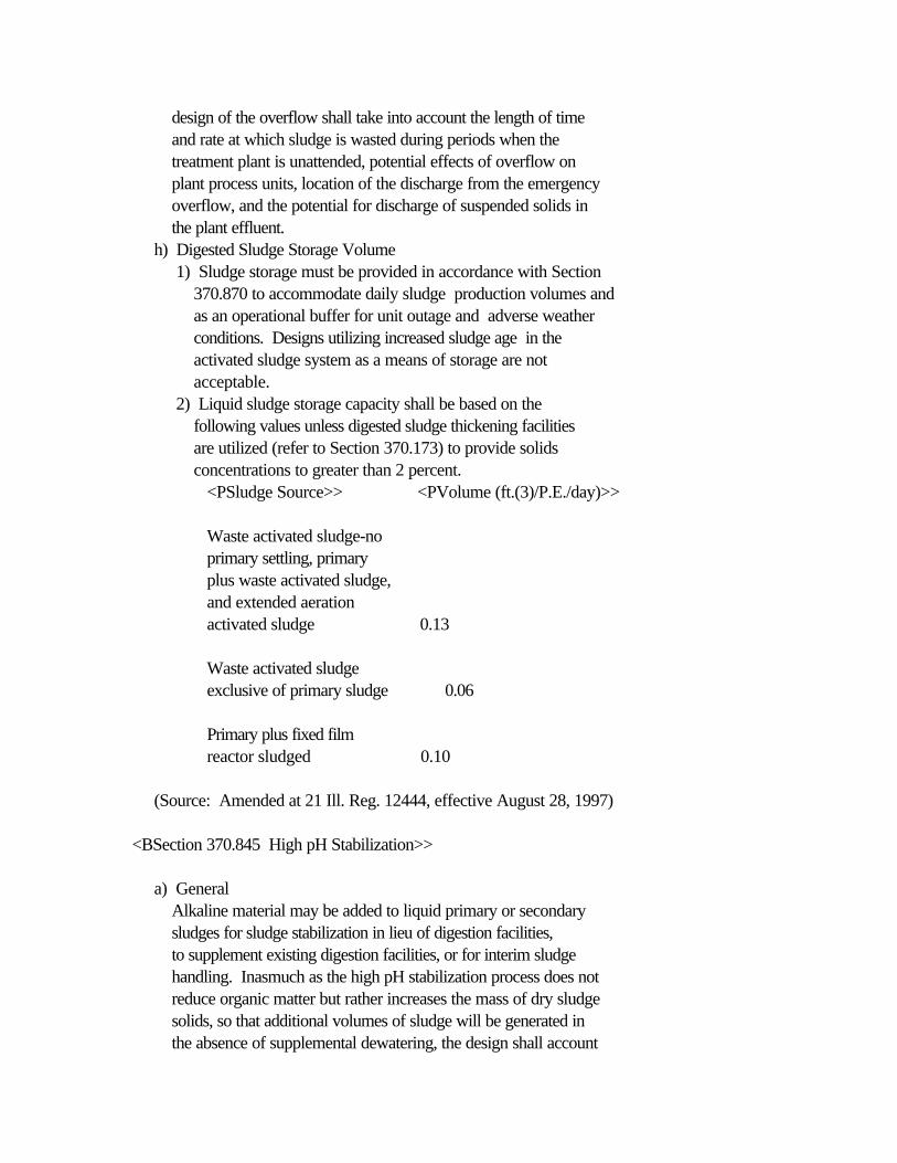
design of the overflow shall take into account the length of time and rate at which sludge is wasted during periods when the treatment plant is unattended, potential effects of overflow on plant process units, location of the discharge from the emergency overflow, and the potential for discharge of suspended solids in the plant effluent. h) Digested Sludge Storage Volume 1) Sludge storage must be provided in accordance with Section 370.870 to accommodate daily sludge production volumes and as an operational buffer for unit outage and adverse weather conditions. Designs utilizing increased sludge age in the activated sludge system as a means of storage are not acceptable. 2) Liquid sludge storage capacity shall be based on the following values unless digested sludge thickening facilities are utilized (refer to Section 370.173) to provide solids concentrations to greater than 2 percent. <PSludge Source>> <PVolume (ft.(3)/P.E./day)>>
Waste activated sludge-no primary settling, primary plus waste activated sludge, and extended aeration activated sludge 0.13
Waste activated sludge exclusive of primary sludge 0.06
Primary plus fixed film reactor sludged 0.10
(Source: Amended at 21 Ill. Reg. 12444, effective August 28, 1997)
<BSection 370.845 High pH Stabilization>>
a) General Alkaline material may be added to liquid primary or secondary sludges for sludge stabilization in lieu of digestion facilities, to supplement existing digestion facilities, or for interim sludge handling. Inasmuch as the high pH stabilization process does not reduce organic matter but rather increases the mass of dry sludge solids, so that additional volumes of sludge will be generated in the absence of supplemental dewatering, the design shall account

for the increased sludge quantities for storage and handling, transportation and disposal methods and associated costs. Alkaline material may be added to dewatered sludges for stabilization pursuant to Section 370.520(b). b) Operational Criteria Sufficient alkaline material shall be added to liquid sludge in order to produce a homogeneous mixture with a minimum pH of 12 after 2 hours of vigorous mixing. Facilities for adding supplemental alkaline material shall be provided to maintain the pH of the sludge during interim sludge storage periods. c) Odor Control and Ventilation Odor control facilities shall be provided for sludge mixing and treated sludge storage tanks that are located within 1/2 mile of residential or commercial areas. Indoor sludge mixing, storage and processing facilities shall have ventilation that meets the ventilation requirements contained in Section 370.410(g)(1-4) and (6) and shall comply with the safety precautions contained in Section 370.560. Adequate facilities shall be provided to condition the exhaust air to meet the applicable substantive and permitting requirements of 35 Ill. Adm. Code Subtitle B: Air Pollution. d) Mixing Tanks and Equipment 1) Tanks Mixing tanks may be designed to operate as either a batch or continuous flow process. A minimum of two tanks of adequate size to provide a minimum of 2 hours of contact time in each tank shall be provided. The following factors shall also be taken into account in determining the number and size of tanks: A) Peak sludge flow rates; B) Storage between batches; C) Dewatering or thickening performed in tanks; D) Repeating sludge treatment due to pH decay of stored sludge; E) Sludge thickening prior to sludge treatment; F) Type of mixing device used and associated maintenance and repair requirements. 2) Equipment Mixing equipment shall be designed to provide vigorous agitation within the mixing tank, to maintain solids in suspension and to provide for a homogenous mixture of the sludge solids and alkaline material. Mixing may be accomplished by either diffused aeration or mechanical
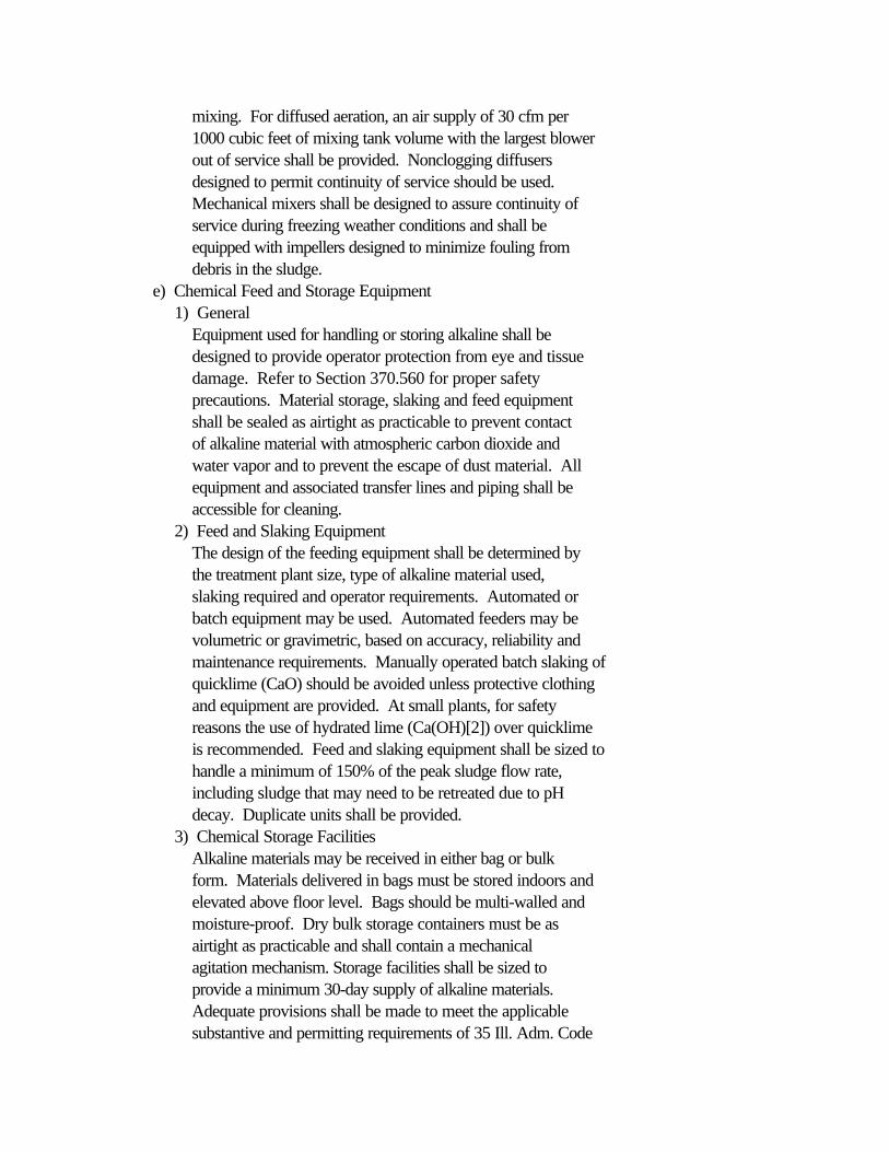
mixing. For diffused aeration, an air supply of 30 cfm per 1000 cubic feet of mixing tank volume with the largest blower out of service shall be provided. Nonclogging diffusers designed to permit continuity of service should be used. Mechanical mixers shall be designed to assure continuity of service during freezing weather conditions and shall be equipped with impellers designed to minimize fouling from debris in the sludge. e) Chemical Feed and Storage Equipment 1) General Equipment used for handling or storing alkaline shall be designed to provide operator protection from eye and tissue damage. Refer to Section 370.560 for proper safety precautions. Material storage, slaking and feed equipment shall be sealed as airtight as practicable to prevent contact of alkaline material with atmospheric carbon dioxide and water vapor and to prevent the escape of dust material. All equipment and associated transfer lines and piping shall be accessible for cleaning. 2) Feed and Slaking Equipment The design of the feeding equipment shall be determined by the treatment plant size, type of alkaline material used, slaking required and operator requirements. Automated or batch equipment may be used. Automated feeders may be volumetric or gravimetric, based on accuracy, reliability and maintenance requirements. Manually operated batch slaking of quicklime (CaO) should be avoided unless protective clothing and equipment are provided. At small plants, for safety reasons the use of hydrated lime (Ca(OH)[2]) over quicklime is recommended. Feed and slaking equipment shall be sized to handle a minimum of 150% of the peak sludge flow rate, including sludge that may need to be retreated due to pH decay. Duplicate units shall be provided. 3) Chemical Storage Facilities Alkaline materials may be received in either bag or bulk form. Materials delivered in bags must be stored indoors and elevated above floor level. Bags should be multi-walled and moisture-proof. Dry bulk storage containers must be as airtight as practicable and shall contain a mechanical agitation mechanism. Storage facilities shall be sized to provide a minimum 30-day supply of alkaline materials. Adequate provisions shall be made to meet the applicable substantive and permitting requirements of 35 Ill. Adm. Code

Subtitle B: Air Pollution. f) Sludge Storage Refer to Section 370.870 for general design considerations for sludge storage facilities. The design shall incorporate the following considerations for the storage of high pH stabilized sludge: 1) Liquid Sludge Liquid high pH stabilized sludge shall be stored in a tank or vessel equipped with rapid sludge withdrawl mechanisms for sludge disposal or retreatment and may not be stored in a lagoon. Provision shall be made for adding alkaline material in the storage tank. Mixing equipment meeting the requirements of subsection (d)(2) above shall be provided in all storage tanks. 2) Dewatered Sludge On-site storage of dewatered high pH stabilized sludge shall be limited to 30 days. Provisions shall be made for rapid retreatment or disposal of dewatered sludge stored on site in case of sludge pH decay. 3) Off-Site Storage There shall be no off-site storage of high pH stabilized sludge unless the Agency has issued a permit for off-site storage. g) Disposal Methods and options for immediate sludge disposal should be used in order to reduce the on-site sludge inventory and the amount of sludge that must be retreated to reduce odors when sludge pH decay occurs. Where land application is used, the sludge must be incorporated into the soil within 24 hours after application.
(Source: Added at 21 Ill. Reg. 12444, effective August 28, 1997)
<BSection 370.850 Sludge Pumps and Piping>>
a) Sludge Pumps 1) Capacity Pump capacities shall be adequate but not excessive. Provision for varying pump capacity is desirable. A rational basis of design shall be provided with the plan documents. 2) Duplicate Units Duplicate units shall be provided at all installations. 3) Type Plunger pumps, screw feed pumps or other types of pumps with
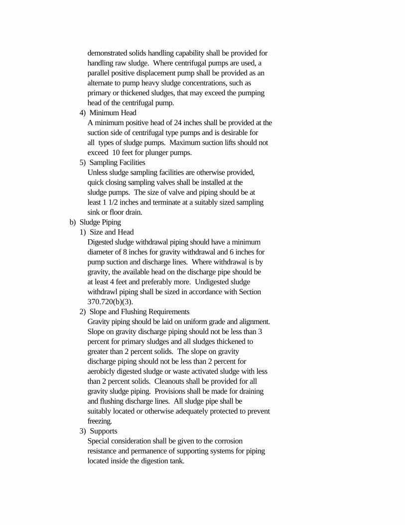
demonstrated solids handling capability shall be provided for handling raw sludge. Where centrifugal pumps are used, a parallel positive displacement pump shall be provided as an alternate to pump heavy sludge concentrations, such as primary or thickened sludges, that may exceed the pumping head of the centrifugal pump. 4) Minimum Head A minimum positive head of 24 inches shall be provided at the suction side of centrifugal type pumps and is desirable for all types of sludge pumps. Maximum suction lifts should not exceed 10 feet for plunger pumps. 5) Sampling Facilities Unless sludge sampling facilities are otherwise provided, quick closing sampling valves shall be installed at the sludge pumps. The size of valve and piping should be at least 1 1/2 inches and terminate at a suitably sized sampling sink or floor drain. b) Sludge Piping 1) Size and Head Digested sludge withdrawal piping should have a minimum diameter of 8 inches for gravity withdrawal and 6 inches for pump suction and discharge lines. Where withdrawal is by gravity, the available head on the discharge pipe should be at least 4 feet and preferably more. Undigested sludge withdrawl piping shall be sized in accordance with Section 370.720(b)(3). 2) Slope and Flushing Requirements Gravity piping should be laid on uniform grade and alignment. Slope on gravity discharge piping should not be less than 3 percent for primary sludges and all sludges thickened to greater than 2 percent solids. The slope on gravity discharge piping should not be less than 2 percent for aerobicly digested sludge or waste activated sludge with less than 2 percent solids. Cleanouts shall be provided for all gravity sludge piping. Provisions shall be made for draining and flushing discharge lines. All sludge pipe shall be suitably located or otherwise adequately protected to prevent freezing. 3) Supports Special consideration shall be given to the corrosion resistance and permanence of supporting systems for piping located inside the digestion tank.
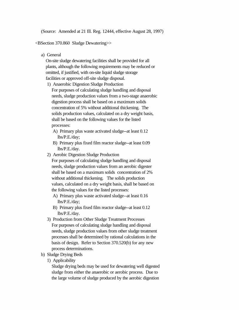
(Source: Amended at 21 Ill. Reg. 12444, effective August 28, 1997)
<BSection 370.860 Sludge Dewatering>>
a) General On-site sludge dewatering facilities shall be provided for all plants, although the following requirements may be reduced or omitted, if justified, with on-site liquid sludge storage facilities or approved off-site sludge disposal. 1) Anaerobic Digestion Sludge Production For purposes of calculating sludge handling and disposal needs, sludge production values from a two-stage anaerobic digestion process shall be based on a maximum solids concentration of 5% without additional thickening. The solids production values, calculated on a dry weight basis, shall be based on the following values for the listed processes: A) Primary plus waste activated sludge--at least 0.12 lbs/P.E./day; B) Primary plus fixed film reactor sludge--at least 0.09 lbs/P.E./day. 2) Aerobic Digestion Sludge Production For purposes of calculating sludge handling and disposal needs, sludge production values from an aerobic digester shall be based on a maximum solids concentration of 2% without additional thickening. The solids production values, calculated on a dry weight basis, shall be based on the following values for the listed processes: A) Primary plus waste activated sludge--at least 0.16 lbs/P.E./day; B) Primary plus fixed film reactor sludge--at least 0.12 lbs/P.E./day. 3) Production from Other Sludge Treatment Processes For purposes of calculating sludge handling and disposal needs, sludge production values from other sludge treatment processes shall be determined by rational calculations in the basis of design. Refer to Section 370.520(b) for any new process determinations. b) Sludge Drying Beds 1) Applicability Sludge drying beds may be used for dewatering well digested sludge from either the anaerobic or aerobic process. Due to the large volume of sludge produced by the aerobic digestion
process, consideration should be given to using a combination of dewatering systems or other means of ultimate sludge disposal. 2) Unit Sizing Sludge drying bed area shall be calculated on a rational basis with the following items taken into account: A) The volume of wet sludge produced by existing and proposed processes. B) Depth of wet sludge drawn to the drying beds. For design calculations purposes a maximum depth of 8 inches shall be utilized. For operational purposes, the depth of sludge placed on the drying bed may vary from the design depth based on the solids content and the type of digestion used. C) Total digester volume and other wet sludge storage facilities. D) Degree of sludge thickening provided after digestion. E) The maximum drawing depth of sludge which can be removed from the digester or other sludge storage facilities without causing process or structural problems. F) The time required on the bed to produce a removable cake. Adequate provision shall be made for sludge dewatering and/or sludge disposal facilities for those periods of time during which outside drying of sludge on beds is hindered by weather. For Illinois that season is considered to extend from early November through at least April. G) Capacities of auxiliary dewatering facilities. 3) Percolation Type Bed Components A) Gravel The lower course of gravel around the underdrains should be properly graded and should be 12 inches in depth, extending at least 6 inches above the top of the underdrains. It is desirable to place this in 2 or more layers. The top layer of at least 3 inches should consist of gravel 1/8 inch to 1/4 inch in size. B) Sand The top course should consist of at least 6 to 9 inches of clean, washed, coarse sand. The effective size of the sand should be in the range of 0.8 to 1.5 millimeters. The finished sand surface should be level. C) Underdrains Underdrains should be at least 4 inches in diameter laid
with open joints. Perforated pipe may also be used. Underdrains should be spaced not more than 20 feet apart. Various pipe materials may be used, so long as they are sufficiently strong and are corrosion resistant. D) Additional Dewatering Provisions Consideration shall be given to providing a means of decanting the supernatant of sludge placed on the sludge drying beds. More effective decanting of supernatant may be accomplished with polymer treatment of the sludge. 4) Walls Walls should be water-tight and extend 18 inches above and at least 6 inches below the surface of the bed. Outer walls should be curbed or extended at least 4 inches above the outside grade elevation to prevent soil from washing on to the beds. 5) Sludge Removal Each bed shall be constructed so as to be readily and completely accessible to mechanical cleaning equipment. Concrete runways spaced to accommodate mechanical equipment shall be provided. Special attention should be given to assure adequate access to the areas adjacent to the sidewalls. Entrance ramps down to the level of the sand bed shall be provided. These ramps shall be high enough to eliminate the need for an entrance end wall for the sludge bed. c) Sludge Lagoons for Dewatering 1) General Lagoons as a means of dewatering digested sludge will be permitted only upon proof that the character of the digested sludge and the design mode of operation are such that offensive odors will not result. Where sludge lagoons are permitted, adequate provisions shall be made for other sludge dewatering facilities or sludge disposal in the event of upset or failure of the sludge digestion process. 2) Location Sludge lagoons shall be located as far as practicable from inhabited areas or areas likely to be inhabited during the lifetime of the structures. 3) Seal Adequate provisions shall be made to seal the lagoon bottoms and embankments to prevent leaching into adjacent soils or

groundwater. Refer to Section 370.930(d)(1)(A), (d)(2)(C) and (d)(2)(D). 4) Access Provisions shall be made for sludge pumping or heavy equipment access for sludge removal from the lagoon. d) Mechanical Dewatering Facilities 1) General Provision shall be made to maintain sufficient continuity of service so that sludge may be dewatered without accumulation beyond storage capacity. The number of vacuum filters, centrifuges, filter presses, belt filters, or other mechanical dewatering facilities should be sufficient to dewater the sludge produced with the largest unit out of service. Unless other standby wet sludge facilities are available, adequate storage facilities of at least 4 days production volume shall be provided. Documentation must be submitted justifying the basis of design of mechanical dewatering facilities. 2) Water Supply Protection The water supply for mechanical dewatering facilities shall meet the requirements of Section 370.550(b). 3) Auxiliary Facilities for Vacuum Filters Back-up vacuum and filtrate pumps shall be provided. It is permissible to have uninstalled back-up vacuum and filtrate pumps for every three or less vacuum filters, provided that the installed units can easily be removed and replaced. At least one filter media replacement unit shall be provided. 4) Ventilation Adequate facilities shall be provided for ventilation of the dewatering area. The exhaust air should be properly conditioned to avoid odor nuisance. Ventilation shall be provided in accordance with Section 370.410(g)(6). 5) Chemical Handling Enclosures Lime-mixing facilities should be completely enclosed to prevent the escape of lime dust. Chemical handling equipment should be automated to eliminate the manual lifting requirement. Refer to Section 370.560. e) Drainage and Filtrate Disposal Drainage from beds or filtrate dewatering units shall be returned to the sewage treatment process at appropriate points and rates. f) Other Dewatering Facilities If it is proposed to dewater sludge by other methods, a detailed description of the process and design data shall accompany the

plans. Refer to Section 370.520(b) for any new process determinations.
(Source: Amended at 21 Ill. Reg. 12444, effective August 28, 1997)<BSection 370.870 Sludge Storage and Disposal>>
a) Storage 1) General Sludge storage facilities shall be provided at all mechanical treatment plants, and may consist of any combination of drying beds, lagoons, separate tanks, additional volume in stabilization units, pad areas or other means to store either liquid or dried sludge. Drainage of supernatant from sludge storage facilities shall be returned to the sewage treatment process at appropriate points and rates. Refer to Section 370.860(b) and (c) for drying bed and lagoon design criteria, respectively. 2) Volume Rational calculations justifying the number of days of storage based on the total sludge handling and disposal system shall be submitted. Refer to Sections 370.840(g) and 370.860(a) for anaerobicly and aerobicly digested sludge production values; values for other stabilization processes shall be justified on the basis of design. If land application is the only means of sludge disposal used at a treatment plant, a minimum of 150 days storage shall be provided, in order to account for inclement weather and cropping practices. b) Disposal 1) Landfilling Sludge and sludge residues may be disposed of in Agency approved municipal solid waste landfill units under the terms and conditions of permits issued by the Agency's Bureau of Land. On-site landfilling shall be conducted in conformance with the design recommendations of the Bureau of Land and must be approved by the Agency's Bureau of Water. 2) Land Application Specific design criteria for land application of sludge are set out in Design Criteria for Sludge Application on Land, 35 Ill. Adm. Code 391. Additional operating criteria may be obtained from applicable Federal regulations. In order to assure compliance with the facility's effluent standards, alternative sludge disposal options to account for inclement
weather and cropping practices are recommended. 3) Sludge Lagoons The use of lagoons for ultimate disposal of sludge is not recommended because of odor potential, area and volume required and possible long term problems from groundwater contamination. If a lagoon is proposed, a hydrogeologic survey must be performed to demonstrate the appropriateness of a disposal lagoon at the particular site. A groundwater monitoring program must be included in any sludge lagoon design. Refer to Section 370.860(c) for lagoon design criteria. 4) Other Disposal Methods A detailed description of the technique and design data shall accompany the plans of any proposal to dispose of sludge by methods other than those specified in this Section. Refer to Section 370.520(b) for any new process determinations.
(Source: Amended at 21 Ill. Reg. 12444, effective August 28, 1997)
SUBPART I: BIOLOGICAL TREATMENT
<BSection 370.900 Trickling Filters>>
a) General 1) Applicability Trickling filters may be used for treatment of sewage amenable to treatment by aerobic biologic processes. Trickling filters shall be preceded by settling tanks equipped with scum and grease collecting devices, or other suitable pretreatment facilities. 2) Design Basis Filters shall be designed so as to provide the required reduction in biochemical oxygen demand, ammonia nitrogen, or to properly condition the sewage for subsequent treatment processes. 3) Multiple Units Multiple trickling filter units capable of independent operation are recommended for all plants and must be provided for those plants where the design average flow exceeds 100,000 gallons per day. Plants not having multiple units shall include other provisions to assure continuity of treatment.
b) Dosing Equipment 1) Distribution A) All hydraulic factors involving proper distribution of sewage on the filter should be carefully calculated and submitted with the basis of design. B) The sewage may be distributed over the filter by rotary distributors or other suitable devices which will permit reasonably uniform distribution to the surface area. At design average flow, the deviation from calculated uniformly distributed volume per square foot of the filter surface shall not exceed plus or minus 10 percent at any point. 2) Dosing and Recirculation A) Sewage may be applied to the filters by siphons, pumps or by gravity discharge from preceding treatment units when suitable flow characteristics have been developed. Application of the sewage should be continuous except for low rate filters. A hydraulic system for recirculation shall be provided for new facilities and should be considered where existing trickling filter units are included in treatment plant upgrading. B) The piping system, including dosing equipment and distributor, shall be designed to provide capacity for the peak hourly flow rate including recirculation rates determined under subsection (h). 3) Distributor Head Requirements For reaction type distributors, a minimum head of 24 inches between low water level in siphon chamber and center of arms is required. Similar allowances shall be made in design for added pumping head requirements where pumping to the reaction type distributor is used. The design shall include the head required at the center column for the full range of flows, taking into account all head losses from the center column back to the dosing facility at all water levels. Calculations shall be submitted to justify the basis of design. 4) Clearance A minimum clearance of 6 inches between media and distributor arms shall be provided. Refer to subsection (e)(4). c) Media 1) Quality The media may be crushed rock, slag or specially manufactured material. The media shall be durable, resistant to spalling

or flaking, and be relatively insoluble in sewage. The top 18 inches shall have a loss by the 20-cycle, sodium sulfate soundness test of not more than 10 percent, as prescribed by ASCE Manual of Engineering Practice, Number 13, the balance to pass a 10-cycle test using the same criteria. Slag media shall be free from iron. Manufactured media shall be resistant to ultraviolet degradation, disintegration, erosion, aging, all common acid and alkalies, organic compounds, and fungus and other biological attack. Such media shall be structurally capable of supporting a man's weight or a suitable access walkway shall be provided to allow for distributor maintenance. 2) Depth The filter media shall have a minimum depth of 6 feet above the underdrains. For rock media filters (subsection (c)(3)(A)), only the top 7 feet of the volume of the filter shall be considered in BOD removal credit computations. For manufactured media filters see subsection (c)(3)(B). 3) Size and Grading of Media A) Rock, Slag and Similar Media i) Rock, slag and similar media shall not contain more than 5 percent by weight of pieces whose longest dimension is 3 times the least dimension. ii) Media shall be free from thin elongated and flat pieces, dust, clay, sand, or fine material and shall conform to the following size and grading when mechanically graded over vibrating screen with square openings: Passing 4 1/2 inch screen - 100% by weight Retained on 3 inch screen - 95-100% by weight Passing 2 inch screen - 0-2% by weight Passing 1 inch screen - 0-1% by weight B) Manufactured Media Suitability of size, space, media configuration and depth will be evaluated on the basis of experience with installations handling similar wastes and loadings. To ensure sufficient void clearance, media with a specific surface area of no more than 30 square feet per cubic foot may be used for filters employed for carbonaceous reduction, and media with a specific surface area of no more than 45 square feet per cubic foot may be used for second stage ammonia reduction. See subsection (c)(1) for quality requirements.
4) Handling and Placing of Media A) Material delivered to the filter site shall be stored on wood planks or other approved clean hard surfaced areas. B) All material shall be rehandled at the filter site and no material shall be dumped directly into the filter. Crushed rock, slag and similar media shall be rescreened or forked at the filter site to remove all fines. C) The material shall be placed by hand to a depth of 12 inches above the tile underdrains and all material shall be carefully placed so as not to damage the underdrains. The remainder of the material may be placed by means of belt conveyors or equally effective methods approved by the engineer. D) Manufactured media shall be handled and placed as recommended by the manufacturer and approved by the engineer. E) Trucks, tractors, or other heavy equipment shall not be driven over the filter during or after construction. d) Underdrainage System 1) Arrangement Underdrains with semi-circular inverts or equivalent should be provided and the underdrainage system shall cover the entire floor of the filter. Inlet openings into the underdrains shall have an unsubmerged gross combined area equal to at least 15 percent of the surface area of the filter. 2) Slope The underdrains shall have a minimum slope of 1 percent. Effluent channels shall be designed to produce a minimum velocity of 2 feet per second at design average flow of application to the filter and shall have adequate capacity for the peak hourly flow rate including the required recirculation flows. 3) Flushing Provision should be made for flushing the underdrains. In small filters, use of a peripheral head channel with vertical vents is acceptable for flushing purposes. Inspection facilities should be provided. 4) Ventilation Requirements for Underdrains The underdrainage system, effluent channels, and effluent pipe should be designed to permit free passage of air. The size of drains, channels, and pipe should be such that not more than 50 percent of their cross-sectional area will be
submerged under the design hydraulic loading. Consideration should be given in the design of the effluent channels to the possibility of increased hydraulic loading. e) Special Features 1) Flooding Provision shall be made in the design of conventional rock filter structures so that the media may be flooded. 2) Maintenance All distribution devices, underdrains, channels and pipes shall be designed so that they may be properly maintained, flushed or drained. 3) Flow Measurement Devices shall be provided to permit measurement of flow to the filter, and of recirculated flows. 4) Protection From Freezing Trickling filters shall be covered to protect from freezing, and to maintain operation and treatment efficiencies. The filter cover shall be constructed of appropriate corrosion resistant materials and designed to allow operator access for maintenance, repair and replacement of the filter dosing equipment. 5) Ventilation of Covered Filters Forced ventilation shall be provided for covered trickling filters to insure adequate oxygen for process requirements. Windows or simple louvered mechanisms so arranged to insure air distribution throughout the enclosure shall be provided. The ventilation facilities shall be designed to allow operator control of air flow in accordance with outside temperature. Design computations showing the adequacy of air flow to satisfy process oxygen requirements shall be submitted. f) Two-Stage Filters The foregoing standards also apply to second stage filters. g) Special Applications 1) Roughing Filters In some instances it is desirable to partially reduce the organic strength of wastewaters. In such cases trickling filters may be used for roughing treatment. Design parameters and contaminant removal efficiencies will be approved on a case-by-case basis. Refer to subsections (h)(2) and (h)(3). 2) Nitrifying Filters Trickling filters may, under favorable conditions, be used as

nitrification devices. Design parameters and contaminant removal efficiencies will be approved on a case-by-case basis. Refer to Section 370.1210(d). h) Efficiency 1) Single Stage, Settling Tank -- No Recirculation Expected reduction of BOD of settled normal domestic wastewater by a single stage filter, packed with crushed rock, slag or similar material and with subsequent settling, shall be determined from Appendix F, Figure No. 3. In developing this curve, loading due to recirculated sewage has not been considered. 2) Single or Multi-Stage, Settling Tank -- Recirculation Expected BOD removal efficiencies may also be determined by theoretical and empirical formula if accompanied by detailed explanation, particularly for roughing filters and for filters with recirculation. (Refer to WEF Manual of Practice (MOP) No. 8, "Design of Municipal Wastewater Treatment Plants", vol. 1 (1992).) 3) Single or Multi-Stage, No Settling Tank -- Recirculation Filters not followed by a settling tank and discharging into a subsequent treatment process shall not be credited with BOD removal efficiencies as in subsections (h)(1) and (h)(2) above. Expected performance in such cases, including filters packed with manufactured media, shall be determined from prototype testing and full-scale plant experience.
(Source: Amended at 21 Ill. Reg. 12444, effective August 28, 1997)
<BSection 370.910 Rotating Biological Contactors>> <B(Repealed)>>
(Source: Repealed at 21 Ill. Reg. 12444, effective August 28, 1997)
<BSection 370.915 Rotating Biological Contactors>>
a) General Wastewater treatment facilities that propose to use rotating biological contactors (RBCs) shall submit to the Agency for review field experience and operational data that demonstrates that observed problems with the process have been solved at similar full scale installations. The Agency will review the claimed field experience against known field conditions and the operational history of observed problems at similar facilities. b) Mechanical Reliability and Structural Integrity
1) The mechanical and structural reliability of the shafts and media subjected to cyclic stress reversals must be demonstrated relative to the design life of the plant and the known weight of the machines based on field experience. 2) The design must show that film thickness will be effectively controlled throughout all parts of the media pack to prevent excessive film weight and water pickup weight due to plugging restrictions. The equipment design must include load cells to warn of the need for film thickness control and to demonstrate the effectiveness of the proposed film thickness control practices. c) Process Reliability 1) Process reliability must be demonstrated, including proven operational control procedures relative to design organic loadings for the unit media area or volume, which satisfactorily insure that the applicable effluent standards are met. The process design shall also include proven operational control procedures that will prevent process functional deficiencies and media plugging that cause the weight to exceed shaft and media structural capabilities during the design life of the plant. 2) The design must show that adequate void clearance (as distinguished from void ratio) is provided to insure that the biological film, including any grease and fats that may accumulate, will not interefere with the flow of liquid and air in the media pack. The Agency will compare the RBC designs under review to past experience with designs used for plastic trickling filter media to accomplish adequate void clearance. 3) The design shall provide for maintaining a minimum of 2.0 mg/l dissolved oxygen in the basin liquor. The effectiveness of the proposed method for maintaining adequate dissolved oxygen will be evaluated based on field experience at similar full scale installations. 4) If pilot testing is proposed, the size of the RBC pilot plant unit and the scope and duration of the testing program on the specific waste that will be treated must be thoroughly documented. The proposed pilot testing program should be submitted to the Agency for comment prior to the initiation of testing. The RBC pilot units must be of prototype scale. Because of differential seasonal weight and plugging field problems, the test period must cover the four seasons, to allow the Agency to evaluate the proposed design against the
experience of existing full scale plants. 5) The process design must include provisions for meeting applicable effluent limits with some units out of service for unit repair, biofilm thickness control, out-of-balance correction and other operational problems. Added units for standby credit will be required to insure compliance with effluent limitations and to prevent mechanical or structural failures during periods of unit outage for maintenance, repair, or process control purposes.
(Source: Added at 21 Ill. Reg. 12444, effective August 28, 1997)
<BSection 370.920 Activated Sludge>>
a) General 1) Applicability A) Biodegradable Wastes The activated sludge process, and its various modifications, may be used to treat wastewater which is amenable to biological treatment. Approval of new activated sludge plants shall be limited to those plants where the design average flow capacity exceeds 0.25 mgd. B) Operation Control Requirements The activated sludge process requires close attention and competent operating supervision. Facilities and appurtenances for routine control and control tests shall be provided at all activated sludge plants. These requirements shall be considered when proposing this type of treatment. C) Energy Requirements This process requires major energy usage to meet aeration demands. Energy costs and potential mandatory emergency public power reduction events, in relation to critical water quality conditions, must be carefully evaluated. Capability of energy usage phasedown while still maintaining process viability, both under normal and emergency energy availability conditions, must be included in the activated sludge design. 2) Specific Process Selection The activated sludge process and its several modifications may be employed to accomplish varied degrees of removal of suspended solids and reduction of 5-day BOD and nitrogenous oxygen demand. Choice of the process most applicable will be

influenced by the proposed plant size, type of waste to be treated, treatability of waste, degree and consistency of treatment required and local factors. All designs shall provide for flexibility in operation. All plants shall be designed to operate in at least two modes. 3) Winter Protection Units shall be protected against freezing. Maximum utilization of earthen bank insulation shall be considered. 4) Process Efficiency The activated sludge process designed within the organic and hydraulic loading limits of these standards, treating normal domestic wastewaters unaffected by surge loadings, long term peak flows, or industrial wastes, may be expected to meet an effluent standard of 20 mg/l CBOD[5] or BOD[5] and 25 mg/l suspended solids when computed on a 30-day monthly average basis. Those installations which are anticipated to be subject to surge loadings, long term peak flows or industrial wastes shall have appropriate design modifications in order to assure consistent effluent quality. b) Preliminary Treatment Effective removal of grit, debris, excessive oil and grease and screening of solids shall be accomplished prior to the activated sludge process. Where primary settling does not precede the activated sludge process, screening with 1/2 inch or smaller clear opening is recommended in order to prevent plugging of return sludge piping and pumps. c) Primary Treatment Bypass When primary settling is used, provision shall also be made for discharging raw sewage directly to the aeration tanks following preliminary treatment. d) Process Organic Loadings The aeration tank capacities and permissible loadings for the several adaptations of the processes shown in the table shall be used. Permissible Organic Loading For The Activated Sludge Processes For Normal Domestic Sewage*
Aeration Tank Organic Loading, Process Mode Plant Design lbs BOD[5]/day/ Average Flow 1000 cu. ft.

_______________________________________________________________ Conventional, Less than 1 mgd Complete Mix, Contact 35 Stabilization,** Step Aeration, Tapered Aeration 1 mgd or greater 50 _______________________________________________________________
Extended Aeration 15*** Single Stage Nitrification _______________________________________________________________ * Where significant industrial wastes will be tributary to the process, design modification shall be made as required by subsection (a)(4), to assure compliance with effluent standards. ** Total aeration capacity includes both contact and reaeration capacities. *** Detention time at Design Average Flow for extended aeration shall be 24 hours. This requirement may govern tank capacity. Detention time for single stage activated sludge for nitrification is governed by Section 370.1210(c)(3)(B). e) Aeration Tanks 1) Multiple Units Multiple tanks shall be provided. Tanks shall be designed so that each tank may be dewatered and operated independently. 2) Tank Geometry The dimensions of each independent mixed liquor aeration tank or return sludge reaeration tank shall be such as to maintain effective mixing and utilization of air. Liquid depths should not be less than 10 feet. The shape of the tank, the location of the inlet and outlet and the installation of aeration equipment shall provide for positive control of short-circuiting through the tank. 3) Freeboard All aeration tanks shall have a freeboard of not less than 18 inches. Greater heights are desirable. Suitable water spray systems or other approved means of froth and foam control shall be provided if foaming is anticipated. 4) Inlet and Outlet Control Inlets and outlets for each aeration tank unit shall be suitably equipped with valves, gates, stop plates, weirs, or

other devices to permit balancing, proportioning, and measuring the flow to and from any unit and to maintain reasonably constant liquid level. The hydraulic elements of the system shall permit the design peak flow to be carried with any single aeration tank out of service. 5) Conduits Channels and pipes carrying liquids with solids in suspension shall be designed to maintain self-cleansing velocities or shall be agitated to keep such solids in suspension at all design rates of flow. Adequate provisions should be made to drain segments of channels which are not being used due to alternate flow patterns. f) Aeration Equipment 1) General A) Aeration requirements depend upon mixing energy, BOD loading, degree of treatment, oxygen uptake rate, mixed liquor suspended solids concentration and sludge age. Aeration equipment shall be capable of maintaining a dissolved oxygen concentration of 2.0 mg/1 in the aeration tanks under all design loads. Energy transfer shall be sufficient to maintain the mixed liquor solids in suspension. B) In the case of nitrification, the oxygen requirement for oxidizing ammonia must be added to the above requirement for carbonaceous BOD removal. The nitrogen oxygen demand (NOD) shall be taken as 4.6 times the diurnal peak ammonia (as nitrogen) content of the influent. In addition, the oxygen demands due to recycle flows such as sludge processing, return from excess flow first flush storage and other similar flows, must be taken into account due to the high concentrations of BOD and ammonia associated with such flows. C) Careful consideration should be given to maximizing oxygen utilization per unit power input. Unless flow equalization is provided, the aeration system should be designed to match the diurnal organic load variation while economizing on power input. 2) Diffused Air Systems A) Except as noted in subsection (f)(2)(B) below, normal aeration tank air requirements shall be based upon a design figure of 1,500 cu. ft. of air supplied/lb. of BOD[5] applied to the aeration tanks. This design figure assumes that the equipment is capable of

transferring 1.0 lb. of oxygen to the aeration tank contents/lb. of BOD[5] applied to the aeration tank. For the extended aeration process, air requirements shall be based on a design figure of 2250 cu. ft. of air supplied per lb. of BOD[5] applied to the aeration tanks to account for oxygen demand for endogenous respiration and ammonia (as nitrogen) for normal strength waste. Refer to Section 370.1210(c) for nitrification requirements. B) Air requirements may be determined based upon transferring 1.0 lb. oxygen/lb. of applied oxygen demand, as determined by subsection (f)(1) above, using standard equations incorporating the factors listed below. When using this design technique, the field oxygen transfer efficiency of the equipment shall be included in the specifications, and the detailed design computations shall be contained in the basis of design: i) Tank depth; ii) Alpha factor of the waste; iii) Beta factor of the waste; iv) Documented aeration device transfer efficiency; v) Minimum aeration tank dissolved oxygen concentrations; vi) Critical wastewater temperature; vii) Plant altitude. C) In the absence of experimentally determined alpha and beta factors for the design described in subsection (f)(2)(B) above, wastewater transfer efficiency shall be assumed to be no more than 50% of clean water efficiency for plants treating primarily (90% or greater) domestic sewage. Treatment plants whose waste contains higher percentages of industrial wastes shall use a correspondingly lower percentage of clean water efficiency and shall submit calculations to justify such a percentage. The design wastewater oxygen transfer efficiency of the equipment shall be included in the specifications. D) The specified capacity of blowers or air compressors, particularly centrifugal blowers, should take into account that the air intake temperature may reach 115 F or higher and the pressure may be less than normal. The specified capacity of the motor drive should also take into account that the intake air may be -20 F or
less and may require oversizing of the motor or a means of reducing the rate of air delivery to prevent overheating or damage to the motor. E) The blowers shall be provided in multiple units, so arranged and in such capacities as to meet the maximum total air demand with the single largest unit out of service. The design shall also provide for varying the volume of air delivered in proportion to the load demand of the plant. F) The air diffusion piping shall be capable of delivering 200 percent of the design air requirements. Air piping systems should be designed such that the friction head loss from the blower outlet (or silencer outlet where used) to the diffuser inlet does not exceed 0.5 psi at 100 percent of design air requirements at average operating conditions for temperature and pressure. G) The spacing of diffusers should be in accordance with the oxygenation requirements through the length of the channel or tank, and should be designed to facilitate adjustments of their spacing without major revision to air header piping. Diffusers in any single assembly shall have substantially uniform pressure loss. H) Individual assembly units of diffusers shall be equipped with control valves, preferably with indicator markings for throttling and for complete shut off. The arrangement of diffusers shall also permit their removal for inspection, maintenance and replacement without dewatering the tank and without shutting off the air supply in the tank, unless the dewatered aeration basins are no more than 25% of the total aeration basin capacity. Total aeration basin capacity shall include the basins in both stages of a two-stage activated sludge process. I) Air filters shall be provided in numbers, arrangement, and capacities to furnish at all times an air supply sufficiently free from dust to prevent clogging of the diffuser system used. 3) Mechanical Aeration Systems A) Oxygen requirements shall be determined in accordance with subsections (f)(2)(B) and (f)(2)(C) above. B) The mechanism and drive unit shall be designed for the expected conditions in the aeration tank in terms of the power performance. Certified testing shall verify

mechanical aerator performance. The design field oxygen transfer efficiency of the equipment shall be included in the specifications, and the detailed design computations shall be contained in the basis of design. C) The mechanical aerators shall be provided in multiple units, so arranged and in such capacities as to maintain all biological solids in suspension, meet maximum oxygen demand and maintain process performance with the largest unit out of service. Provision shall be made for varying the amount of oxygen transferred in proportion to the load demand on the plant. D) Due to high heat loss, the mechanism as well as subsequent treatment units shall be protected from freezing. E) Motors, gear housing, bearings and grease fittings shall be easily accessible and protected from inundation and spray as necessary for proper functioning of the unit. g) Return Sludge Equipment 1) Return Sludge Rate The rate of sludge return, expressed as a percentage of design average flow of sewage, shall be variable between limits of 15 and 100 percent. 2) Return Sludge Pumps A) If motor driven return sludge pumps are used, the maximum return sludge capacity shall be obtained with the largest pump out of service. The rate of sludge return shall be varied by such means as variable speed motors or drives, multiple constant speed pumps, or telescoping valves. A positive head should be provided on pump suctions. Pumps shall be capable of passing spheres of at least 3 inches in diameter. Pump suction and discharge openings shall be at least 4 inches in diameter. B) If air lift pumps are used for returning sludge from each settling tank, no standby unit shall be required provided that the design of the air lifts is such as to facilitate their rapid and easy cleaning. Air lifts should be at least 3 inches in diameter and provided with adjustable air valving to permit flow control in accordance with subsection (g)(1) above. 3) Return Sludge Piping Suction and discharge piping should be at least 4 inches in diameter and should be designed to maintain a velocity of not
less than 2 feet per second when return sludge facilities are operating at normal return sludge rates. Suitable devices for observing, measuring, sampling and controlling return activated sludge flow from each settling tank shall be provided. 4) Waste Sludge Control Waste sludge control facilities should have a maximum capacity of not less than 25 percent of the average rate of sewage flow and function satisfactorily at rates of 0.5 percent of average sewage flow. Means for observing, measuring, sampling and controlling waste activated sludge flow shall be provided. Waste sludge may be discharged to the primary settling tank, concentrator or thickening tank, sludge digestion tank, vacuum filters, or any practical combination of these units. Refer to Sections 370.820 and 370.710(b)(1)(A).
(Source: Amended at 21 Ill. Reg. 12444, effective August 28, 1997)
<BSection 370.930 Waste Stabilization Ponds and Aerated Lagoons>>
a) Supplement To Engineer's Report 1) The engineer's report shall contain pertinent information on location, geology, soil conditions, area for expansion, and any other factors that will affect the feasibility and acceptability of the proposed treatment. 2) Supplementary Field Survey Data The following information must be submitted in addition to that required in Section 370.111: A) The location and direction of all residences, commercial development, and water supplies within 1/2 mile of the proposed pond. B) Soil borings to determine surface and subsurface soil characteristics of the immediate area and their effect on the construction and operation of a pond located on the site. C) Data demonstrating anticipated percolation rates at the elevation of the proposed pond bottom. D) A description, including maps showing elevations and contours of the site and adjacent area suitable for expansion. E) Sulfate content of the water supply. F) Identification of the location, depth and discharge
point of any field tile in the immediate area of the proposed site. b) Location 1) Distance From Habitation A pond site should be as far as practicable from habitation or any area which may be built up within a reasonable future period. 2) Prevailing Winds If practicable, ponds should be located so that local prevailing winds will be in the direction of uninhabited areas. Preference should be given sites which will permit an unobstructed wind sweep across the ponds, especially in the direction of the local prevailing winds. 3) Surface Runoff Adequate provisions shall be made to divert storm water around the ponds and otherwise protect pond embankments. 4) Ground Water Contamination The requirements of the Illinois Groundwater Protection Act [415 ILCS 55] shall be taken into account in the siting of ponds. Ponds should not be located proximate to water supplies and other facilities subject to contamination or located in areas of porous soils and fissured rock formations. If conditions dictate using such a site, then the potential for and the means necessary to combat groundwater contamination shall be critically evaluated in the engineer's report. In such locations, the Agency will require groundwater monitoring wells. 5) Geology Ponds shall not be located in areas subject to sink holes and mine subsidence. Soil borings and tests to determine the characteristics of surface soil and subsoil shall be made a part of preliminary pond site selection surveys. Gravel and limestone areas should be avoided; however, where conditions dictate locating ponds in such areas and the minimum separation between the pond bottom and gravel or limestone will be less than 10 feet, the Agency shall be contacted about the necessary precautions. c) Basis Of Design 1) Organic Loading A) Waste Stabilization Ponds The organic loading on each cell shall not exceed the loadings listed below. If more accurate design information for the particular type waste is not
submitted and supported by the engineer, subsequent cells shall be sized for an organic loading of 25% of each preceding cell. i) North of Illinois Highway 116 (Pontiac) 22 lbs. BOD per acre per day. ii) Between Illinois Highway 116 and U.S. Highway 50, 26 lbs. BOD per acre per day. iii) South of U.S. Highway 50 (Salem-Carlyle) 30 lbs. BOD per acre per day. B) Aerated Lagoons The organic loading for aerated lagoons shall not exceed 0.5 lb. BOD[5] day per 1,000 cu. ft. first cell nor 0.3 lb. BOD[5] day per 1,000 cu. ft. on any subsequent cells. If more accurate design information for the particular type waste is not submitted and supported by the engineer, the second and third cells shall be sized for an organic loading of 25% of each preceding cell. 2) Depth A) Waste Stabilization Ponds The minimum operating liquid depth for waste stabilization ponds should be 2 feet. The maximum operating liquid depth shall be based on design storage requirements and shall not be less than 5 feet. B) Aerated Lagoons The design water depth for aerated lagoons should be 10 to 15 feet. This depth limitation may be altered depending on the aeration equipment, waste strength, climatic and geological conditions. 3) Aeration Requirements For Aerated Lagoons A) Aeration systems shall be designed to provide, with the largest unit out of service, a minimum of 1,500 cu. ft. of air/lb. of BOD[5] in the raw waste (1.5 lbs. of oxygen/lb. of BOD[5] plus oxygen required to oxidize the ammonia present in the raw waste). The aeration equipment shall be located to ensure proper mixing and distribution of oxygen in proportion to oxygen demand in multiple cells. Splash type aerators with motors above the water surface may not be used. B) Where hose type diffusers are used, the holes shall be of sufficient size to prevent plugging by dissolved solids incrustation. 4) Multiple Cells A minimum of two cells to be operated in series or parallel

should be provided for all waste stabilization ponds when they are utilized as a part of the primary and secondary treatment process. The number of cells required for aerated lagoons are dependent upon the degree of treatment required. Refer to subsection (c)(6). 5) Pond Shape The shape of all primary cells should be such that there are no narrow or elongated portions. Round, square, or rectangular ponds with a length not exceeding 3 times the width are considered most desirable. No islands, peninsulas, or coves should be permitted. Dikes should be rounded at corners to minimize accumulations of floating materials. 6) Solids Removal All lagoon systems shall include effective solids removal facilities. Design criteria for acceptable solids removal facilities are contained in Subpart K. Other solids removal facilities may be approved in accordance with Section 370.520(b). d) Construction Details 1) Embankments and Dikes A) Material Embankments and dikes shall be constructed of relatively impervious materials and compacted to at least 90% Standard Proctor density to form a stable structure. Vegetation and other unsuitable material shall be removed from the area upon which the embankment is to be placed. B) Top Width The minimum embankment top width should be 8 feet to permit access of maintenance vehicles. Lesser top widths will be considered for very small installations. C) Maximum Embankment Slopes i) Inner Slopes: 3 horizontal to 1 vertical. ii) Outer Slopes: 3 horizontal to 1 vertical. D) Minimum Embankment Slopes i) Inner Slopes: 4 horizontal to 1 vertical. Flatter slopes are sometimes specified for larger installations because of wave action but have the disadvantage of added shallow areas conducive to emergent vegetation.
ii) Outer Slopes: Outer slopes shall be sufficient to prevent surface runoff from entering the ponds. E) Freeboard Minimum freeboard shall be 3 feet except for very small installations 2 feet may be acceptable. F) Erosion Control Requirements For effective erosion control on the lagoon embankments, both seeding and riprap (or acceptable alternate) are required. i) Seeding Embankments shall be seeded from the outside toe to 1 foot above the high water line on the dikes, measured on the slope. Perennial type, low growing, spreading grasses that withstand erosion and can be kept mowed are most satisfactory for seeding of embankments. In general, alfalfa and other long rooted crops should not be used in seeding, since the roots of this type plant are apt to impair the water holding efficiency of the dikes. The County Agricultural Extension Agent can usually advise as to hardy, locally suited permanent grasses which would be satisfactory for embankment seeding. ii) Riprap Riprap (or acceptable alternate) shall be placed on the inner slope of the embankments from 1 foot above the high water mark to 1 foot below the low water level. Riprap shall be comprised of a two-layer system consisting of a minimum 4-inch layer of coarse aggregate that meets the Illinois Department of Transportation (IDOT) Standard Specification for Road and Bridge Construction adopted January 1, 1997 for the gradations in the range of CA-6 through CA-10 and a minimum 12-inch layer of stone. The rock layer shall consist of evenly graded material with a maximum weight of 150 pounds per piece and shall meet the IDOT gradations for rock of either Grade No. 3 or 4. 2) Pond Bottom A) Uniformity Finished elevations shall not be more than 3 inches from the average elevation of the bottom. Shallow or
feathering fringe areas usually result in locally unsatisfactory conditions. B) Vegetation The bottom shall be cleared of vegetation and debris. Organic material thus removed shall not be used in the dike core construction. However, suitable topsoil relatively free of debris may be used as cover material on the outer slopes of the embankment. C) Soil Soil used in constructing the pond bottom (not including the seal) shall be relatively incompressible and tight. Porous topsoil shall be removed. Porous areas, such as gravel or sandy pockets, shall be removed and replaced with well compacted clay. The entire bottom shall be compacted at or up to 4% above the optimum water content to at least 90% Standard Proctor density. D) Seal The pond bottom and embankments shall be sealed such that seepage loss through the seal is as low as possible. Seals consisting of soils, bentonite or synthetic liners may be used, provided that the permeability, durability and integrity of the proposed material is demonstrated for anticipated conditions. The results of a testing program that substantiates the adequacy of the proposed seal shall be incorporated into or accompany the engineering report. Standard ASTM procedures or similar accepted testing methods shall be used for all tests. i) A seal consisting of soil materials shall have a thickness of at least 24 inches and a permeability of less than 1x10(-7) cm per second. Provision shall be made in the specifications for demonstrating the permeability of the seal after completion of construction and prior to filling the pond. ii) For a seal that consists of a synthetic liner, seepage loss through the liner shall not exceed a quantity equivalent to seepage loss through a soil seal as described above. E) Prefilling Prefilling the pond after completion of testing is recommended in order to protect the seal from weed growth, to prevent drying and cracking and to reduce

odor during initial operation. The pond dikes must be completely prepared as described in subsection (d)(1)(F). Synthetic liners shall be protected from damage during installation and filling. 3) Influent Lines A) Material Any generally accepted material for underground sewer construction will be given consideration for the influent line to the pond. The material selected should be adapted to local conditions. Special consideration must be given to the character of the wastes, possibility of septicity, exceptionally heavy external loadings, abrasion, the necessity of reducing the number of joints, soft foundations, and similar problems. B) Manholes A readily accessible manhole shall be installed at the terminus of the trunk sewer or the force main, unless the force main discharges directly to the lagoon as described in subsection (d)(3)(H). The manhole shall be located as close to the dike as topography permits and its invert should be at least 6 inches above the maximum operating level of the pond to provide sufficient hydraulic head without surcharging the manhole. Surcharging of the sewer upstream from the inlet manhole is not permitted. C) Grade i) Influent line can be placed at zero grade and should be located along the bottom of the pond so that the top of the pipe is just below the average elevation of the pond bottom. The pipe shall have adequate seal below it. ii) The laying of the influent pipe on the surface of the pond bottom is prohibited. D) Point of Discharge Influent lines to the primary cell should terminate at approximately the third point farthest from the outlet structure. For interconnecting piping to secondary cells refer to subsection (d)(4)(B). E) Flow Distribution Flow distribution structures shall be designed to effectively split hydraulic and organic loads proportionally to primary cells. Refer to Section 370.520(f).
F) Submerged Inlets Submerged inlet lines shall discharge horizontally into a shallow, saucer-shaped depression which should extend below the pond bottom not more than the diameter of the influent pipe plus 1 foot. G) Discharge Apron The end of the discharge line should rest on a suitable concrete apron with a minimum size of 2 feet square. H) Force Mains Force mains discharging directly to lagoons are permitted if the force main has a freefall discharge into the lagoon and is not turned upward at the point of discharge. The point of discharge shall be at approximately the third point farthest from the outlet structure and the pipe shall be sloped for drainage into the lagoon to avoid freezing. I) Anti-Seep Collars Anti-seep collars shall be used on all piping passing through or under the lagoon embankments. 4) Outlet Structures and Interconnecting Piping A) Outlet Structure i) Outlet structures shall be designed to allow the operating level of the pond to be adjusted to permit operation at depths of 2 feet to the maximum depth. The design shall also allow effluent to be drawn from various depths below all operating levels. All structures and devices such as weirs, gates and valves shall be watertight and capable of being easily adjusted by the operator without the need of additional mechanical equipment. Wooden stop-planks are not acceptable for level control. ii) Drawoff lines should not be located any lower than 12 inches off the bottom to control eroding velocities and avoid pickup of bottom deposits. iii) A locking device should be provided to prevent unauthorized access to the level control facilities. iv) When possible, the outlet structure should be located on the windward side to prevent short circuiting. The outlet structure shall be properly baffled to prevent the discharge of floating material. v) Consideration must be given in the design of all

structures to protect against freezing or ice damage under winter conditions. B) Interconnecting Piping and Unit Bypass i) Interconnecting piping and overflows should be constructed of materials that will withstand damage during construction and operation, giving special consideration to damage that may occur during compaction of embankments and damage to shallow piping. Piping shall be sized to allow transfer of maximum flows without raising the lagoon water level by more than 6 inches in the upstream cell. In no case shall interconnecting pipe be less than 8 inches in diameter. Interconnecting piping between cells should be valved or provided with other arrangements to regulate flow between structures and permit flexible depth control. ii) The interconnecting pipe to the secondary cell should discharge horizontally near the lagoon bottom to minimize need for erosion control measures and should be located as near the dividing dike as construction permits. iii) Piping and valves shall be provided so that each cell can be operated independently of any other cell. Provision shall be made for independent cell dewatering. C) Anti-Seep Collars Anti-seep collars shall be used on all interconnecting and outlet piping passing through or under the lagoon embankments. 5) Miscellaneous A) Fencing The pond area shall be enclosed with a suitable fence to preclude livestock and discourage trespassing. A vehicle access gate of sufficient width to accommodate mowing equipment shall be provided. All access gates shall be provided with locks. B) Warning Signs Appropriate signs should be provided along the fence around the pond to designate the nature of the facility and advise against trespassing. C) Flow Measurement, Sampling and Level Gauge Provisions for flow measurement and sampling shall be provided on the inlet and outlet. Pond level gauges
shall be provided. The NPDES permit monitoring requirements for the facility shall be taken into account. Elapsed time meters on pumps or calibrated weirs may be used as flow measurement devices for lagoons. D) Sludge Removal When an existing lagoon is to be upgraded, the project design shall provide for removal of any sludge accumulation in the existing lagoon. The sludge removed shall be disposed of in accordance with IPCB regulations.
(Source: Amended at 21 Ill. Reg. 12444, effective August 28, 1997)
<BSection 370.940 Intermittent Sand Filtration for Secondary Treatment>>
a) Applicability Use of the intermittent sand filter for secondary treatment is generally limited to weak to normal strength wastewaters which are amenable to biological treatment. Cold weather operational problems may preclude the use of this process unless the influent temperature to the filter is adequate to allow efficient filter operation necessary to meet the applicable effluent standards. b) Pretreatment Requirements Wastewaters applied to intermittent sand filters must be substantially free of grit, debris, oil and grease, floating and suspended materials, and components which inhibit biological processes and cause rapid clogging of the filter. Special consideration shall be given to the design of preceding treatment units, including dosing facilities, to limit heat loss during winter operation. c) Multiple Units Intermittent sand filters shall be provided in multiple units, designed for independent operation and maintenance. d) Location Intermittent sand filters treating septic tank or primary effluent should be restricted to relatively isolated locations or otherwise modified in order to minimize odor nuisances. e) Recirculation Recirculation of filter effluent may be practiced in order to attenuate and equalize organic and hydraulic loads to the filter, and improve unit process efficiency, control odors, and improve day-to-day reliability.
1) Rate A recirculation rate of up to 300% of the settled sewage load to the filter may be provided. 2) Variability The capability of varying the recirculation rate allows greater process control and optimization of process efficiency. This feature shall be included where recirculation is provided. f) Dosing 1) Dosing Volumes The dosing facilities shall be designed for a capacity of 2,500 gallons per 1,000 sq. ft. of filter bed to be dosed at any given time. 2) Dosing Rates for Siphons or Pumps Siphons (at minimum head) or pumps shall have a discharge capacity at least 100% in excess of the maximum rate of inflow to the dosing tank, including recirculation, and at average head, at least 90 gallons per minute per 1,000 square feet. 3) Discharge Line Capacity The discharge lines to the beds shall have sufficient capacity to permit the full rated discharge of the siphons or pumps. g) Construction Details 1) Earth Base The earth base of the filters shall be sloped to the underdrains. 2) Underdrains The sand filter shall be provided with open-joint or perforated pipe underdrains. They should be sloped to the outlet and spaced not to exceed 10 foot centers. Vertical riser vents shall be provided at both ends of each underdrain pipe and shall be located as not to be overtopped at maximum dosing depth. 3) Media A) Gravel Base Clean graded gravel, preferably placed in at least three layers, should be placed around the underdrains and to a depth of at least 6 inches over the top of the underdrains. Crushed stone may not be used in lieu of gravel. Suggested gradings for the three layers are: 1 1/2" to 3/4", 3/4" to 1/4", 1/4" to 1/8". B) Sand
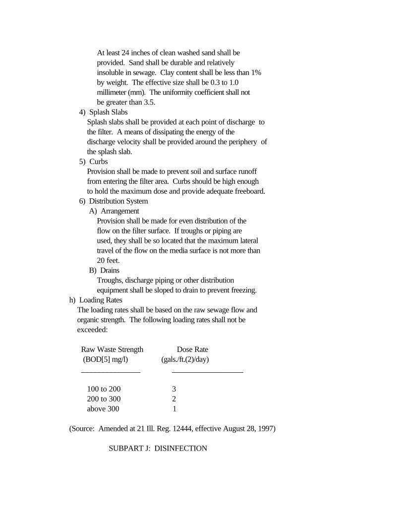
At least 24 inches of clean washed sand shall be provided. Sand shall be durable and relatively insoluble in sewage. Clay content shall be less than 1% by weight. The effective size shall be 0.3 to 1.0 millimeter (mm). The uniformity coefficient shall not be greater than 3.5. 4) Splash Slabs Splash slabs shall be provided at each point of discharge to the filter. A means of dissipating the energy of the discharge velocity shall be provided around the periphery of the splash slab. 5) Curbs Provision shall be made to prevent soil and surface runoff from entering the filter area. Curbs should be high enough to hold the maximum dose and provide adequate freeboard. 6) Distribution System A) Arrangement Provision shall be made for even distribution of the flow on the filter surface. If troughs or piping are used, they shall be so located that the maximum lateral travel of the flow on the media surface is not more than 20 feet. B) Drains Troughs, discharge piping or other distribution equipment shall be sloped to drain to prevent freezing. h) Loading Rates The loading rates shall be based on the raw sewage flow and organic strength. The following loading rates shall not be exceeded:
Raw Waste Strength Dose Rate (BOD[5] mg/l) (gals./ft.(2)/day) _______________ __________________
100 to 200 3 200 to 300 2 above 300 1
(Source: Amended at 21 Ill. Reg. 12444, effective August 28, 1997)
SUBPART J: DISINFECTION

<BSection 370.1000 General>>
Where needed to meet applicable standards, disinfection of the effluentshall be provided. The design shall provide for meeting both the bacterialstandards and any disinfectant residual limits applicable to the effluent.
(Source: Amended at 21 Ill. Reg. 12444, effective August 28, 1997)
<BSection 370.1010 Disinfection Process Selection>>
a) The disinfection process should be selected after due consideration of waste characteristics, type of treatment processes provided prior to disinfection, waste flow rates, waste pH, disinfectant demand rates, current technology application, cost of equipment, chemical availability, power costs and maintenance requirements. Areawide public safety shall be considered where large liquid chlorine or sulfur dioxide containers are to be handled. b) Chlorine may be used in the form of liquid chlorine or calcium or sodium hypochlorite. Dechlorination will be required where necessary to meet applicable chlorine residual effluent limitations. c) An ultra-violet radiation system may be used as an alternative disinfection process. d) Other alternative means of disinfection will be evaluated according to the provisions of Section 370.520(b).
(Source: Amended at 21 Ill. Reg. 12444, effective August 28, 1997)
<BSection 370.1020 Chlorine Disinfection>>
a) Type of Feed Equipment The types of chlorine feed equipment include: 1) Vacuum solution feed by gas; 2) Direct gas feed; 3) Hypochlorite solution positive displacement pump feed; 4) Hypochlorite tablet feed. b) Selection of Feed Equipment The selection of the type of chlorine feed equipment shall take into account operator safety and overall public safety relative to the proximity of the sewage treatment plant to populated areas and to the security of the gas cylinder or container storage.
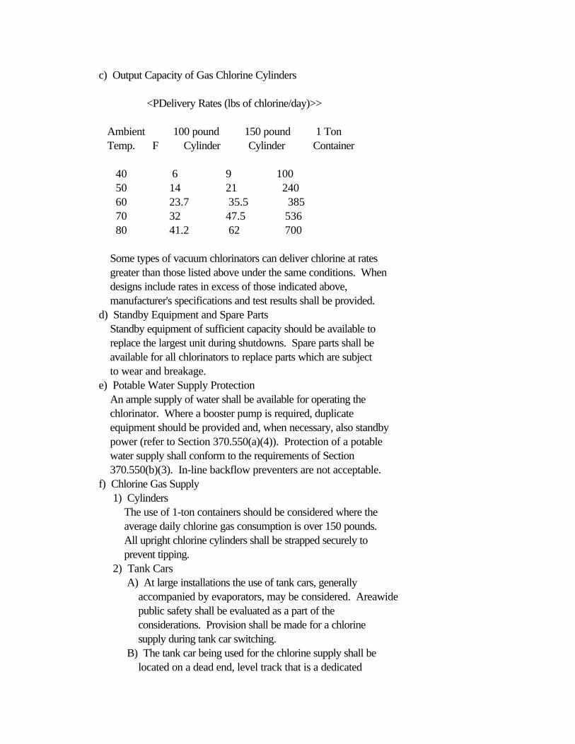
c) Output Capacity of Gas Chlorine Cylinders
<PDelivery Rates (lbs of chlorine/day)>>
Ambient 100 pound 150 pound 1 Ton Temp. F Cylinder Cylinder Container
40 6 9 100 50 14 21 240 60 23.7 35.5 385 70 32 47.5 536 80 41.2 62 700
Some types of vacuum chlorinators can deliver chlorine at rates greater than those listed above under the same conditions. When designs include rates in excess of those indicated above, manufacturer's specifications and test results shall be provided. d) Standby Equipment and Spare Parts Standby equipment of sufficient capacity should be available to replace the largest unit during shutdowns. Spare parts shall be available for all chlorinators to replace parts which are subject to wear and breakage. e) Potable Water Supply Protection An ample supply of water shall be available for operating the chlorinator. Where a booster pump is required, duplicate equipment should be provided and, when necessary, also standby power (refer to Section 370.550(a)(4)). Protection of a potable water supply shall conform to the requirements of Section 370.550(b)(3). In-line backflow preventers are not acceptable. f) Chlorine Gas Supply 1) Cylinders The use of 1-ton containers should be considered where the average daily chlorine gas consumption is over 150 pounds. All upright chlorine cylinders shall be strapped securely to prevent tipping. 2) Tank Cars A) At large installations the use of tank cars, generally accompanied by evaporators, may be considered. Areawide public safety shall be evaluated as a part of the considerations. Provision shall be made for a chlorine supply during tank car switching. B) The tank car being used for the chlorine supply shall be located on a dead end, level track that is a dedicated

siding. The tank car shall be protected from accidental bumping by other railway cars by a locked de-rail device, a closed lock switch, or both. The area shall be clearly posted "DANGER-CHLORINE." The tank car shall be secured by adequate fencing with locked gates for personnel and rail access. C) The tank car site shall be provided with an operating platform at the unloading point that allows for easy access to the protective housing on the tank car for flexible feed line connection and valve operation. Area lighting adequate for night time operation and maintenance shall be provided. 3) Scales A) Scales shall be provided for weighing cylinders and containers at all plants using chlorine gas. B) At large plants, indicating and recording scales are recommended. At a minimum, a platform scale shall be provided. Scales shall be made of corrosion-resistant material. Scales should be recessed unless hoisting equipment is provided or the scales are low enough to allow the cylinders to be rolled onto them. 4) Evaporators Where manifolding of several cylinders or containers will be required to evaporate sufficient chlorine, consideration should be given to liquid drawoff and installation of an evaporator. 5) Leak Detection and Controls A bottle of ammonium hydroxide solution should be available for detecting chlorine leaks. Consideration should also be given to the provision of caustic soda solution reaction tanks for absorbing the contents of leaking 1-ton containers where such containers are in use. Also, when cylinders, containers or tank cars are used, a leak repair kit approved by the Chlorine Institute shall be provided. At installations using over 150 pounds of chlorine gas per day consideration should be given to the installation of automatic gas detection and related alarm equipment. g) Piping and Connections 1) Piping systems should be as simple as possible, and shall be specially selected and manufactured to be suitable for chlorine service, with a minimum number of joints. Piping should be well supported and protected against temperature extremes.
2) The chlorine system piping shall be color coded and labeled to distinguish it from sulfur dioxide and other plant piping. Where sulfur dioxide is used, the piping and fittings for chlorine and sulfur dioxide systems shall be designed so that interconnection between the two systems cannot occur. h) Housing 1) Container and Equipment Location Containers and feed equipment should be located indoors, in a suitable fire-resistant building. Gas cylinders should be protected from direct sunlight if not located indoors. A) Separation If gas chlorination equipment and chlorine cylinders or containers are to be housed in a building used for other purposes, the chlorine cylinders or containers and equipment shall be located in an isolated room. This room shall not contain any sulfonation equipment, sulfur dioxide cylinders or other equipment unrelated to chlorination. Common walls to other areas of the building shall be gastight. Doors to this room shall open only to the outside of the building and shall be equipped with panic hardware. Rooms shall be at ground level and shall permit easy access to all equipment. Storage areas should be separated from the feed area. B) Inspection Window A clear gastight window shall be installed in the chlorinator room to permit the units to be viewed and gauges to be read without entering the room. C) Heat Chlorinator housing facilities shall be provided with a means of heating so that a temperature of at least 60 F can be maintained. Where chlorine gas is to be withdrawn from cylinders or containers, the cylinders or containers shall be maintained at essentially room temperature. The room shall be protected from excessive heat. If liquid chlorine is to be withdrawn from the cylinders or containers to an evaporator unit, the feed cylinders or containers may be located in an unheated area. 3) Ventilation For Gas Chlorination Systems A) Forced, mechanical ventilation shall be installed which will provide 1 complete air change per minute. The entrance to the air exhaust duct from the room shall be within 12 inches of the floor and the point of discharge

shall be so located as not to contaminate the air in the immediate vicinity of the entrance door to the chlorinator room or ventilation inlet or window or entrance door to any buildings or inhabited areas. Where the public may be subjected to extensive exposure to chlorine in case of chlorine leaks, scrubbers may be required on the ventilation discharge. B) The chlorination room air inlets shall be so located as to provide cross ventilation with air and at such temperature that will not adversely affect the chlorination equipment. The vent hose from the chlorinator shall discharge to the outside atmosphere above grade. 4) Electrical Controls The controls for the fans and lights shall be provided at those locations where it is necessary to enter the chlorination room and shall automatically operate when the door is opened and continue to operate when the operator enters the room and the door is closed. Provision shall be made for manual operation of controls from the outside of the room without opening the door. 5) Outdoor Cabinet Housing Outdoor shallow cabinet-type units, with wide opening doors, that are shallow enough not to need or require operator entry, may be used to house the containers and feed equipment. Use of such cabinets shall be limited to small plants that provide seasonal disinfection or use less than 10 pounds of chlorine per day. Only two chlorine gas cylinders of 150 pounds or less on line may be housed in the cabinets. The following items shall be provided for in the design: A) The cabinet structure shall be located on and securely anchored to a concrete slab sized to allow for safe transport and handling of the cylinders. The structure and slab shall be capable of withstanding expected wind loadings on the cabinet. The design of the cabinet support slab shall take into account the effects of frost and settling due to soil stability. Flexible piping connections should be considered for lines connected to the cabinet. B) The cabinet shall be protected from direct sunlight to prevent overheating of the chlorine cylinders. C) The cabinet doors shall extend the full width of the long side of the cabinet structure so that the full
interior of the cabinet is exposed with the door open. Provision shall be made to secure the open doors while the operator is changing cylinders and maintaining the feed equipment. D) The cabinet depth shall not exceed 24 inches. The feed equipment shall be positioned to allow easy access for maintenance and to allow observation of the gauges and meters. E) Provision shall be made for chains, wall mounted fastener hooks or similar means for anchoring the chlorine cylinders to prevent tipping. F) The cabinet structure shall be corrosion resistant to chlorine gas. G) Where electrical power is available, the cabinet should be placed in a well-lighted area. i) Respiratory Protection Equipment Respiratory protection equipment meeting the requirements of the National Institute for Occupational Safety and Health (NIOSH) shall be available at all installations where chlorine gas is handled and shall be stored in a convenient location outside of any room where chlorine is used or stored. The respiratory protection units shall use compressed air, have at least a 30-minute capacity, and be compatible with or exactly the same as NIOSH-approved units used by the local fire department. Instructions for using, testing, and replacing mask parts shall be posted. At large installations, consideration should be given to providing acid suits and fire suits. j) Application of Chlorine 1) Contact Period After thorough mixing, a minimum contact period of 15 minutes at design peak hourly flow or maximum rate of pumpage shall be provided. 2) Chlorinator Dosing Rate Capacity Chlorinators shall be designed to have a capacity adequate to produce an effluent that will meet the applicable bacterial limits. Where necessary to meet the operating ranges, multiple units shall be provided for adequate peak capacity and for a sufficiently low feed rate on turn down to allow proper chlorine residual. The chlorination system shall be designed on a rational basis and calculations justifying the equipment sizing and number of units shall be submitted for the whole operating range of flow rates, including the minimum turn down capacity for the type of control to be
used. System design considerations shall include the controlling sewage flow meter (sensitivity and location), telemetering equipment and chlorinator controls. For treated normal domestic sewage the following dosing capacity, based on design average flow, is suggested (see Section 370.520(c)(1)):
<PType of Treatment>> <PDosage (mg/l)>>
Primary Settled Sewage 20 Lagoon Effluent (unfiltered) 20 Trickling Filter Plant Effluent 10 Lagoon Effluent (filtered) 10 Activated Sludge Plant Effluent 6 Activated Sludge Plants with Chemical Addition 4 Filtered Effluent Following Mechanical Biological Treatment 4
k) Contact Tank 1) Mechanical means of sludge removal is recommended and should be provided unless multiple chlorine tanks are provided. Portable deck-level vacuum cleaning equipment may be used for small treatment plants. Provisions for draining contact tanks not equipped with mechanical sludge removal equipment shall be provided, with the drain flow returned to process for treatment. 2) Exception to the requirement of duplicate contact tanks may be granted if the contact tank follows a sand filter or if the main treatment works is a waste stabilization pond, with provisions for storing the sewage flow for several days while the contact tank is being cleaned. 3) Adequate mixing during the chlorine contact period shall be insured by the installation of adequate baffling, air or other mixing equipment. Facilities for the retention and removal of floating scum shall be provided.
(Source: Amended at 21 Ill. Reg. 12444, effective August 28, 1997)
<BSection 370.1021 Dechlorination>>
a) General Dechlorination of sewage plant effluents may be required to reduce

toxicity due to chlorine residuals. b) Feed Equipment 1) Type The common types of dechlorination feed equipment using sulfur compounds include: A) Vacuum solution feed of sulfur dioxide gas. B) Positive displacement pump feed or aqueous solutions of sulfite or bisulfite products. 2) Selection of Feed Equipment The selection of the type of feed equipment using sulfur compounds shall include consideration of operator safety and overall public safety relative to the proximity of the sewage treatment plant to populated areas and the security of the gas cylinder storage. The selection and design of sulfur dioxide feeding equipment shall take into account the fact that the gas reliquifies very easily. c) Output Capacity of Sulfur Dioxide Cylinders The number of feed cylinders or containers necessary to meet the design delivery rates shall be based on the physical, thermodynamic and chemical properties for sulfur dioxide. Refer to the Compressed Gas Association publication CGA G-3-1988 "Sulfur Dioxide" or other standard reference sources for information on sulfur dioxide properties. d) Standby Equipment and Spare Parts Standby equipment should be available of sufficient capacity to replace the largest unit during shutdown. Spare parts to replace parts that are subject to wear and breakage shall be available for all sulfonators. e) Potable Water Supply An ample supply of water shall be available for operating the sulfonator. Where a booster pump is required duplicate equipment should be provided and, when necessary, standby power. (Refer to Section 370.550(a)(4).) Protection of the potable water supply shall conform to the requirements of Section 370.550(b)(6). In-line back flow preventers may not be used. f) Sulfur Dioxide Gas Supply 1) Cylinders The use of 1-ton containers should be considered where the average daily sulfur dioxide consumption is over 150 pounds. All upright sulfur dioxide cylinders shall be strapped securely to prevent tipping. 2) Tank Cars A) The use of tank cars, generally accompanied by
evaporators, may be considered for large installations. Areawide public safety shall be evaluated as part of the considerations. Continuity of sulfur dioxide supply shall be maintained during tank car switching. B) The tank car being used for the sulfur dioxide supply shall be located on a dead end, level track that is a dedicated siding. The tank car shall be protected from accidental bumping by other railway cars by a locked de-rail device, a closed lock switch, or both. The area shall be clearly posted "DANGER-SULFUR DIOXIDE." The tank car shall be secured by adequate fencing with locked gates for personnel and rail access. C) The tank car site shall be provided with an operating platform at the unloading point that allows for easy access to the protective housing on the tank car for flexible feed line connection and valve operation. Area lighting adequate for night time operation and maintenance shall be provided. 3) Scales A) Scales shall be provided for weighing cylinders or containers at all plants using sulfur dioxide gas. B) At large plants indicating and recording scales are recommended. At a minimum, a platform scale shall be provided. Scales shall be made of corrosion resistant material. Scales should be recessed unless hoisting equipment is provided or the scales are low enough to allow the cylinders to be rolled onto them. 4) Evaporator Where the manifolding of several cylinders or containers will be required to evaporate sufficient sulfur dioxide, consideration should be given to liquid drawoff and installation of an evaporator. A liquid nitrogen gas padding system to enhance the liquid sulfur dioxide delivery rate should be considered. 5) Leak Detection and Controls Sulfur dioxide leak detection equipment shall be provided which has a sensitivity level equal to that of ambient air pollution monitoring equipment. Where cylinders, one-ton containers and tank cars are used, a leak repair kit that is compatible for use with sulfur dioxide gas shall be provided. Leak repair kits used for chlorine gas (Section 370.1020(f)(5)) equipped with gasket materials suitable for service with sulfur dioxide may be used. (See paragraphs

10.4 and 13.2 of "Sulfur Dioxide," Compressed Gas Association, Inc., Publication CGA G-3-1988 for a discussion of suitable materials.) Refer to Section 370.560. g) Piping and Connections 1) Piping systems should be as simple as possible, with a minimum number of joints, and shall be suitable for sulfur dioxide service. Piping should be well supported and protected against temperature extremes. 2) The piping for the sulfur dioxide system shall be color-coded and labeled to distinguish it from chlorine piping, and the system shall be designed so that interconnections with chlorine piping cannot occur. h) Housing 1) Container and Equipment Location Containers and feed equipment should be located inside a fire resistant building. Gas cylinders and containers should be protected from direct sunlight. A) Isolation If gas sulfonation equipment and sulfur dioxide cylinders will be located in a building also used for other purposes, the sulfur dioxide equipment and containers shall be located in an isolated room that shall not contain any chlorination equipment, chlorine containers or any other equipment unrelated to sulfonation. Common walls to other areas of the building shall be gastight. Doors to the room shall open only to the outside and shall be equipped with panic hardware. Rooms shall be at ground level and shall allow easy access to all equipment. Storage areas should be separated from feed areas; sulfur dioxide and chlorine cylinders shall be stored in separate areas. B) Inspection Window A clear gastight window shall be installed in the sulfonate room to permits the units to be viewed and gauges to be read without entering the room. 2) Heat Sulfonator housing facilities shall be provided with a means of heating so that cylinder temperatures can be maintained in the range of 90 to 100 F when sulfur dioxide is to be withdrawn from the cylinder. The sulfonator room shall be protected from excessive heat. 3) Ventilation for Sulfur Dioxide Systems A) Forced, mechanical ventilation that will provide one
complete air change per minute shall be installed in the sulfonator room. The entrance to the exhaust duct from the room shall be within 12 inches from the floor and the point of discharge shall be located so as not to contaminate the air in the immediate vicinity of the door to the sulfonator room or ventilation inlet to any buildings or inhabited areas. B) The air inlets to the sulfator room shall be located so as to provide cross ventilation with air and at temperatures that will not adversely affect the sulfonation equipment. The vent hose from the sulfonator shall discharge to the outside atmosphere above grade. 4) Electrical Controls Controls for fans and lights shall be located at the entrances to the sulfonation room and shall automatically operate when the door is opened and continue in operation when the operator enters the room and the door is closed. Provision shall be made for operation of the fans and lights from the outside without opening the door. i) Respiratory Protection Equipment Respiratory protection equipment meeting the requirements of NIOSH shall be available at all installations where sulfur dioxide gas is handled and shall be stored in a convenient location outside of any room where sulfur dioxide is used or stored. The units shall use compressed air, shall have at least a 30-minute capacity and shall be the same as or compatible with NIOSH-approved units used by the local fire department. Instructions for using, testing and replacing mask parts shall be posted. At large installations, providing acid suits and fire suits should be considered. j) Application of Sulfonation Chemicals 1) Contact Period and Reaeration A minimum contact period of 30 seconds, including mixing time, at design peak hourly flow or maximum pumpage rate shall be provided. Mechanical mixers are required unless the mixing facility will provide the necessary hydraulic turbulence to assure thorough mixing. A means of reaeration shall be provided to insure maintenance of the required dissolved oxygen concentration in the effluent and the receiving stream after sulfonation. When choosing a reaeration method the fact that excess sulfur dioxide, formed when the dechlorinating chemicals are dissolved in water, may be expected to consume 1 mg of dissolved oxygen for every 4
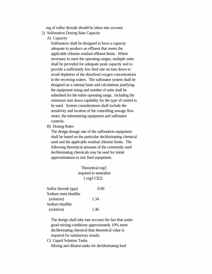
mg of sulfur dioxide should be taken into account. 2) Sulfonation Dosing Rate Capacity A) Capacity Sulfonators shall be designed to have a capacity adequate to produce an effluent that meets the applicable chlorine residual effluent limits. Where necessary to meet the operating ranges, multiple units shall be provided for adequate peak capacity and to provide a sufficiently low feed rate on turn down to avoid depletion of the dissolved oxygen concentrations in the receiving waters. The sulfonator system shall be designed on a rational basis and calculations justifying the equipment sizing and number of units shall be submitted for the entire operating range, including the minimum turn down capability for the type of control to be used. System considerations shall include the sensitivity and location of the controlling sewage flow meter, the telemetering equipment and sulfonator controls. B) Dosing Rates The design dosage rate of the sulfonation equipment shall be based on the particular dechlorinating chemical used and the applicable residual chlorine limits. The following theoretical amounts of the commonly used dechlorinating chemicals may be used for initial approximations to size feed equipment.
Theoretical mg/l required to neutralize 1 mg/l Cl[2]
Sulfur dioxide (gas) 0.90 Sodium meta bisulfite (solution) 1.34 Sodium bisulfite (solution) 1.46
The design shall take into account the fact that under good mixing conditions approximately 10% more dechlorinating chemical than theoretical value is required for satisfactory results. C) Liquid Solution Tanks Mixing and dilution tanks for dechlorinating feed
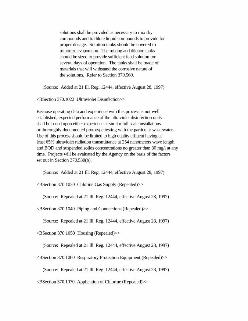
solutions shall be provided as necessary to mix dry compounds and to dilute liquid compounds to provide for proper dosage. Solution tanks should be covered to minimize evaporation. The mixing and dilution tanks should be sized to provide sufficient feed solution for several days of operation. The tanks shall be made of materials that will withstand the corrosive nature of the solutions. Refer to Section 370.560.
(Source: Added at 21 Ill. Reg. 12444, effective August 28, 1997)
<BSection 370.1022 Ultraviolet Disinfection>>
Because operating data and experience with this process is not wellestablished, expected performance of the ultraviolet disinfection unitsshall be based upon either experience at similar full scale installationsor thoroughly documented prototype testing with the particular wastewater.Use of this process should be limited to high quality effluent having atleast 65% ultraviolet radiation transmittance at 254 nanometers wave lengthand BOD and suspended solids concentrations no greater than 30 mg/l at anytime. Projects will be evaluated by the Agency on the basis of the factorsset out in Section 370.530(b).
(Source: Added at 21 Ill. Reg. 12444, effective August 28, 1997)
<BSection 370.1030 Chlorine Gas Supply (Repealed)>>
(Source: Repealed at 21 Ill. Reg. 12444, effective August 28, 1997)
<BSection 370.1040 Piping and Connections (Repealed)>>
(Source: Repealed at 21 Ill. Reg. 12444, effective August 28, 1997)
<BSection 370.1050 Housing (Repealed)>>
(Source: Repealed at 21 Ill. Reg. 12444, effective August 28, 1997)
<BSection 370.1060 Respiratory Protection Equipment (Repealed)>>
(Source: Repealed at 21 Ill. Reg. 12444, effective August 28, 1997)
<BSection 370.1070 Application of Chlorine (Repealed)>>

(Source: Repealed at 21 Ill. Reg. 12444, effective August 28, 1997)
<BSection 370.1080 Sampling and Testing>>
a) Facilities shall be included for collecting samples, as monitoring requirements warrant, of the disinfected effluent. b) Where chlorine disinfection is used, equipment shall be provided for measuring chlorine residual using accepted test procedures. c) Where required by the Agency, equipment shall also be provided for measuring fecal coliform using accepted test procedures.
(Source: Amended at 21 Ill. Reg. 12444, effective August 28, 1997)
SUBPART K: TERTIARY FILTRATION
<BSection 370.1100 Applicability>>
Various types of tertiary filters may be used to polish effluents ofsecondary treatment plants.
<BSection 370.1110 Type>>
a) Granular media filtration is considered to include the following type units: 1) High rate single, dual and multi-media of either the pressure or gravity type with facilities for backwashing. 2) Low rate sand filters dosed intermittently or periodically. b) Low rate filtration is generally limited in use to small installations. c) For miscellaneous considerations, refer to Section 370.203(j).
<BSection 370.1120 High Rate Filtration>>
a) Design Considerations Care should be given in the selection of pumping equipment ahead of filter units to minimize shearing of flow particles. Consideration should be given in the plant design to providing flow-equalization facilities to moderate filter influent quality and quantity. b) Pretreatment A positive method shall be provided to control the suspended solids loading to the filters. Equipment for the feeding of
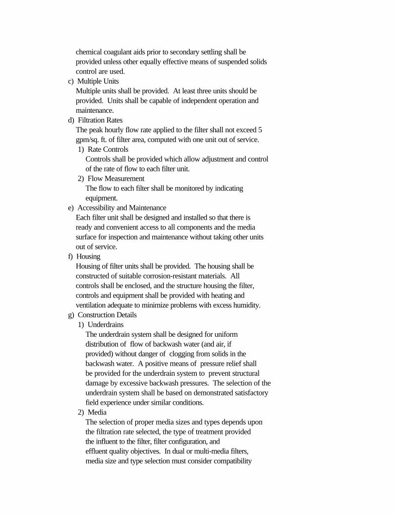
chemical coagulant aids prior to secondary settling shall be provided unless other equally effective means of suspended solids control are used. c) Multiple Units Multiple units shall be provided. At least three units should be provided. Units shall be capable of independent operation and maintenance. d) Filtration Rates The peak hourly flow rate applied to the filter shall not exceed 5 gpm/sq. ft. of filter area, computed with one unit out of service. 1) Rate Controls Controls shall be provided which allow adjustment and control of the rate of flow to each filter unit. 2) Flow Measurement The flow to each filter shall be monitored by indicating equipment. e) Accessibility and Maintenance Each filter unit shall be designed and installed so that there is ready and convenient access to all components and the media surface for inspection and maintenance without taking other units out of service. f) Housing Housing of filter units shall be provided. The housing shall be constructed of suitable corrosion-resistant materials. All controls shall be enclosed, and the structure housing the filter, controls and equipment shall be provided with heating and ventilation adequate to minimize problems with excess humidity. g) Construction Details 1) Underdrains The underdrain system shall be designed for uniform distribution of flow of backwash water (and air, if provided) without danger of clogging from solids in the backwash water. A positive means of pressure relief shall be provided for the underdrain system to prevent structural damage by excessive backwash pressures. The selection of the underdrain system shall be based on demonstrated satisfactory field experience under similar conditions. 2) Media The selection of proper media sizes and types depends upon the filtration rate selected, the type of treatment provided the influent to the filter, filter configuration, and effluent quality objectives. In dual or multi-media filters, media size and type selection must consider compatibility
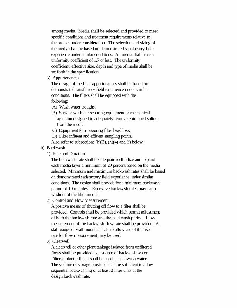
among media. Media shall be selected and provided to meet specific conditions and treatment requirements relative to the project under consideration. The selection and sizing of the media shall be based on demonstrated satisfactory field experience under similar conditions. All media shall have a uniformity coefficient of 1.7 or less. The uniformity coefficient, effective size, depth and type of media shall be set forth in the specification. 3) Appurtenances The design of the filter appurtenances shall be based on demonstrated satisfactory field experience under similar conditions. The filters shall be equipped with the following: A) Wash water troughs. B) Surface wash, air scouring equipment or mechanical agitation designed to adequately remove entrapped solids from the media. C) Equipment for measuring filter head loss. D) Filter influent and effluent sampling points. Also refer to subsections (h)(2), (h)(4) and (i) below. h) Backwash 1) Rate and Duration The backwash rate shall be adequate to fluidize and expand each media layer a minimum of 20 percent based on the media selected. Minimum and maximum backwash rates shall be based on demonstrated satisfactory field experience under similar conditions. The design shall provide for a minimum backwash period of 10 minutes. Excessive backwash rates may cause washout of the filter media. 2) Control and Flow Measurement A positive means of shutting off flow to a filter shall be provided. Controls shall be provided which permit adjustment of both the backwash rate and the backwash period. Flow measurement of the backwash flow rate shall be provided. A staff gauge or wall mounted scale to allow use of the rise rate for flow measurement may be used. 3) Clearwell A clearwell or other plant tankage isolated from unfiltered flows shall be provided as a source of backwash water. Filtered plant effluent shall be used as backwash water. The volume of storage provided shall be sufficient to allow sequential backwashing of at least 2 filter units at the design backwash rate.

4) Chlorination of Filter Backwash Provision shall be made for periodic chlorination of filter backwash water (or filter influent) to control slime growths. The flows from the cleaning of the filters shall be returned to the head of the plant. Refer to subsection (h)(6)(A) below. 5) Backwash Pumps Where used, backwash pumps shall be provided in multiple units, designed for independent operation and maintenance. Pumps shall be sized in accordance with subsection (h)(1) above to provide the required backwash rate with one unit out of service and should be of equal size. The total dynamic head of the pump shall be limited to that needed for the application so that undue stress of the underdrain system will not occur. Refer to subsection (g)(1) above. 6) Mudwell A mudwell or other plant tankage shall be provided to hold backwash water from the filters. The volume provided shall be sufficient to hold the water generated by the backwashing of two filter units including the water in and above the filter media prior to filtration. Refer to subsection (h)(1) above. Filter backwash shall be returned to process or otherwise treated to insure compliance with applicable standards. A) Return Rate The rate of return of filter backwash to the treatment units shall not exceed 15 percent of the design average flow to the treatment units. Refer to subsection (j)(1) below and Section 370.520(g). B) Mudwell Return Pumps Backwash return pumps, where used, shall be provided in multiple units designed for independent operation and maintenance. The units shall be sized to provide the required pumping rate with the largest unit out of service. Refer to subsection (h)(6)(A) above. i) Control Panel Automatic controls shall be provided, with a manual override on the control panel for operating equipment, including each individual valve essential to the filter operation. j) Miscellaneous Considerations 1) Return Backwash Loadings The return of backwash water and solids will result in increases in the hydraulic and suspended solids loads to the
preceding treatment units. Design of these units shall take into account the increased loads. 2) Oil and Grease Filters at treatment plants treating wastewaters containing above normal concentrations of greases or similar materials should be of the gravity type. Facilities should be considered for the periodic addition of chemicals to remove greases in such cases. 3) Proprietary Equipment Proprietary equipment not conforming to the requirements of this section will be evaluated on a case-by-case basis in accordance with Section 370.520(b).
(Source: Amended at 21 Ill. Reg. 12444, effective August 28, 1997)
<BSection 370.1130 Low Rate Intermittent or Periodically Dosed Sand Filters>>
a) Applicability 1) Intermittent sand filters may be used to polish secondary effluents. The process removes residual suspended solids and soluble biochemical oxygen demand and converts ammonia to nitrate. (See Section 370.1210(b).) 2) Cold weather operational problems may preclude the use of this process unless the influent temperature to the filter is adequate to allow efficient filter operation necessary to meet the applicable effluent standards. 3) Because of manual labor necessary to clean, maintain and replace sand on the filters, the application is usually limited to small waste treatment plants. b) Design Criteria The criteria of Section 370.940(b), (c), and (f)(3), are generally applicable to intermittent sand filters used as tertiary filtration units. 1) Dosing Volumes The dosing facilities shall be sized to provide for a 12-hour dosing cycle for each bed. 2) Siphon or Pump Capacity Siphons (at minimum head) or pumps shall have a discharge capacity at least 100 percent in excess of the maximum rate of inflow to the dosing tank, including recirculation, and at average head, at least 90 gallons per minute per 1,000 square feet being dosed. 3) Recirculation

Provision for recirculation of filter effluent may be included to improve process flexibility. A) Rate A recirculation rate of up to 100% of design average flow to the filter may be provided. B) Variability Capability for varying the recirculation rate shall be provided. 4) Loading Rates The hydraulic load of secondary wastewater applied to supplemental intermittent sand filters shall not exceed 15 gallons per day (gpd)/sq. ft. More conservative application rates should be provided for low quality filter influents. Refer to subsection (d)(3) below. c) Construction Details The criteria of Section 370.940(g) are generally applicable to tertiary intermittent sand filters. Also, refer to subsection (d). d) Special Design Considerations in Lagoon Systems 1) General Low rate sand filter systems that are intermittently or periodically dosed may be used to reduce suspended solids from multicell aerated or nonaerated sewage lagoon treatment plants. 2) Cold Weather Design Lagoons which have sand filters shall be designed to provide storage of flows received during cold weather when the filter is expected to be inoperable. 3) Hydraulic Loading A) The filter area design considerations must include the following: i) The total annual flow volume to be treated (Section 370.520(c)(1)) including wet weather flows if the lagoons are to be used for wet weather storage. ii) The effective net days annually for filter operation excluding cold weather shut-down and filter maintenance time. iii) Lagoon effluent quality. iv) Extent and reliability of flow data from the sewer system. B) Where sewer system conditions are not favorable or industrial waste loadings are expected to increase algae blooms, the loading rate should be limited to 10

gal./ft.(2)/day. 4) Dosing Considerations A) Methods of Operation The design should include allowance for periodic dosing of varied volumes onto the filter while the filter discharge is shut off, then to be followed by a filtration period to completely empty the filter at a controlled rate. B) Depth The filter shall be designed for flexibility of dosing depth from 6 inches to 2 feet. C) Valving, Piping, Flow Measurement i) The filter shall be provided with valving to allow shutting off and controlling rate of flow both onto and from the filter. A flow measurement weir or flume shall be provided both on the inlet and outlet of the filter for operator control of the dosing and filtration rates under the falling head conditions. ii) The outlet valving, piping and flow measurement shall be designed to allow complete drainage of the filter underdrains at the end of the filter cycle to insure aerobic conditions in the filter during the rest period. D) Dosing Inlet Structures The dosing inlet structures shall be designed to dissipate inlet velocity and prevent sand scouring during the dosing period at the high dose rates. The inlet structures should be arranged to not interfere with maintenance of the sand surface. 5) Filter Containment Structure The filter containment may be of vertical concrete walls on three sides (refer to subsection (d)(6) below) or sloped earthen berms with impervious lining, constructed to insure that no ground surface runoff or silts get onto the sand surface. A freeboard of 1 foot above the maximum design dosing depth should be provided. 6) Access Ramps The filter should be designed with a ramp on one end sloped and surfaced for access to the edge of the bed by wheeled vehicle to facilitate removing and replacement of sand. For larger filters, concrete tracks at the level of the sand surface may be desirable to reduce distance sand must be

handled.
(Source: Amended at 21 Ill. Reg. 12444, effective August 28, 1997)
SUBPART L: NUTRIENT REMOVAL
<BSection 370.1200 Phosphorus Removal by Chemical Treatment>>
a) General 1) Method Addition of lime or the salts of aluminum or iron may be used for the chemical removal of soluble phosphorus. The phosphorus reacts with the calcium, aluminum or iron ions to form insoluble compounds. These insoluble compounds may be flocculated with or without the addition of a coagulant aid such as a polyelectrolyte to facilitate separation by sedimentation. 2) Design Basis A) Preliminary Testing Laboratory, pilot or full-scale trial of various chemical feed systems and treatment processes are recommended to determine the achievable performance level, cost-effective design criteria, and ranges of required chemical dosages. B) System Flexibility Systems shall be designed with sufficient flexibility to allow for several operational adjustments in chemical feed location, chemical feed rates, and for feeding alternate chemical compounds. b) Process Requirements 1) Dosage The required chemical dosage shall include the amount needed to react with the phosphorus in the wastewater, the amount required to drive the chemical reaction to the desired state of completion, and the amount required due to inefficiencies in mixing or dispersion. Excessive chemical dosage should be avoided. 2) Chemical Selection A) The choice of lime or the salts of aluminum or iron should be based on the wastewater characteristics and the economics of the total system. B) When lime is used it may be necessary to neutralize the
high pH prior to subsequent treatment in secondary biological systems or prior to discharge in those flow schemes where lime treatment is the final step in the treatment process. 3) Chemical Feed Points Selection of chemical feed points shall include consideration of the chemicals used in the process, necessary reaction times between chemical and polyelectrolyte additions, and the wastewater treatment processes and components utilized. Considerable flexibility in feed location should be provided, and multiple feed points are recommended. 4) Flash Mixing Each chemical must be mixed rapidly and uniformly with the flow stream. Where separate mixing basins are provided, they should be equipped with mechanical mixing devices. The detention period should be at least 30 seconds. 5) Flocculation The particle size of the precipitate formed by chemical treatment may be very small. Consideration should be given in the process design to the addition of synthetic polyelectrolytes to aid settling. The flocculation equipment should be adjustable in order to obtain optimum floc growth, control deposition of solids, and prevent floc destruction. 6) Liquid - Solids Separation A) The velocity through pipes or conduits from flocculation basins to settling basins should not exceed 1,5 feet per second in order to minimize floc destruction. Entrance works to settling basins should also be designed to minimize floc shear. B) Settling basin design shall be accordance with criteria outlined in Subpart G. For design of the sludge handling system, special consideration should be given to the type and volume of sludge generated in the phosphorus removal process. 7) Filtration Effluent filtration shall be considered where effluent phosphorus concentrations of less than 1 mg/1 must be achieved. c) Feed Systems 1) Location A) All liquid chemical mixing and feed installations should be installed on corrosion-resistant pedestals and elevated above the highest liquid level anticipated
during emergency conditions. Refer to Section 370.147(b)(2)(A). B) Lime feed equipment should be located so as to minimize the length of slurry conduits. All slurry conduits shall be accessible for cleaning. 2) Liquid Chemical Feed Pumps A) Liquid chemical feed pumps should be of the positive displacement type with variable feed rate. Pumps shall be selected to feed the full range of chemical quantities required for the phosphorus mass loading conditions anticipated with the largest unit out of service. B) Screens and valves shall be provided on the chemical feed pump suction lines. C) An air break or anti-siphon device shall be provided where the chemical solution stream discharges to the transport water stream to prevent an induction effect resulting in overfeed. D) Consideration shall be given to providing pacing equipment to optimize chemical feed rates. 3) Dry Chemical Feed System A) Each dry chemical feeder shall be equipped with a dissolver which is capable of providing a minimum 5-minute retention at the maximum feed rate. B) Polyelectrolyte feed installations should be equipped with two solution vessels and transfer piping for solution make-up and daily operation. C) Make-up tanks shall be provided with an eductor funnel or other appropriate arrangement for wetting the polymer during the preparation of the stock feed solution. Adequate mixing should be provided by a large-diameter low-speed mixer. d) Storage Facilities 1) Size Storage facilities shall be sufficient to insure that an adequate supply of the chemical is available at all times. Exact size required will depend on size of shipment, length of delivery time, and process requirements. Storage for a minimum of a 10-day supply should be provided. 2) Location A) The liquid chemical storage tanks and tank fill connections shall be located within a containment structure having a capacity exceeding the total volume
of all storage vessels. Valves on discharge lines shall be located adjacent to the storage tank and within the containment structure. B) Auxiliary facilities, including pumps and controls, within the containment area shall be located above the highest anticipated liquid level. Containment areas shall be sloped to a sump area and shall not contain floor drains. C) Bag storage should be located near the solution make-up point to avoid unnecessary transportation and housekeeping problems. 3) Accessories A) Platforms, stairways, and railings should be provided as necessary to afford convenient and safe access to all filling connections, storage tank entries, and measuring devices. B) Storage tanks shall have reasonable access provided to facilitate cleaning. e) Other Requirements 1) Materials All chemical feed equipment and storage facilities shall be constructed of materials resistant to chemical attack by all chemicals normally used for phosphorus treatment. 2) Temperature, Humidity and Dust Control Precautions shall be taken to prevent chemical storage tanks and feed lines from reaching temperatures likely to result in freezing or chemical crystallization at the concentrations employed. Enclosure heating or insulation may be required. Consideration must be given to temperature, humidity and dust control in all chemical feed room areas. 3) Cleaning Consideration shall be given to the accessibility of piping. Piping should be installed with plugged wyes, tees or crosses at changes in direction to facilitate cleaning. 4) Drains and Drawoff Above-bottom drawoff from chemical storage or feed tanks shall be provided to avoid withdrawal of settled solids into the feed system. A bottom drain shall also be installed for periodic removal of accumulated settled solids. f) Hazardous Chemical Handling The requirements of Section 370.147(b), Hazardous Chemical Handling, shall be met. g) Sludge Handling
1) General Consideration shall be given to the type and additional capacity of the sludge handling facilities needed when chemicals are added. 2) Dewatering Design of dewatering systems should be based, where possible, on an analysis of the characteristics of the sludge to be handled. Consideration should be given to the ease of operation, effect of recycle streams generated, production rate, moisture content, dewaterability, final disposal, and operating cost.
<BSection 370.1210 Ammonia Control>>
a) General Ammonia control can be accomplished by physical, chemical, biological and ion-exchange techniques. These criteria contain design standards for a limited number of biological types and configurations of ammonia control systems. Other types and configuration of systems will be evaluated in accordance with Section 370.520(b). 1) Process Selection A) Biological systems, normally used to accomplish secondary levels of treatment, may be adapted to function as nitrification systems. In applications of the fixed growth processes staged biological treatment is normally provided. The single stage activated sludge process has been found to be reliable for nitrification and is more commonly used than the two-stage activated sludge process. B) Because operating data and experience for the fixed growth processes for nitrification are not well established, expected performance in all cases shall be based upon experience at similar full scale installations or thoroughly documented prototype testing with the particular wastewater. The design shall provide the necessary flexibility to perform satisfactorily within the range of expected waste characteristics and temperatures. 2) Alkalinity and pH Control Biological utilization of ammonia to produce nitrates is consumptive of available alkalinity in the ratio of 7.14 pounds alkalinity (as CaCO[3]) per pound of ammonia nitrogen
(as N) oxidized. The determination of the need for added alkalinity must be calculated and included in the basis of design to be submitted with the plan documents for Agency approval. The following factors shall be taken into account in determining the amount of alkalinity to be added: A) The available alkalinity in the raw wastewater and any sidestreams; B) The total ammonia load (including sidestreams such as flows from digesters and sludge handling facilities) imposed on the process; C) The alkalinity needed to maintain pH levels in the range of 7.2 to 8.4. 3) Load Equalization Load equalization shall be considered to limit peak loadings of ammonia from plant sidestreams or slug sources on the sewer system. For the fixed growth biological nitrification processes, the ammonia loading peaks shall be limited to 150% of the design average ammonia loading value. b) Intermittent Sand Filters Intermittent sand filters, used in conjunction with various primary and secondary treatment systems, may be considered for use as a biological process to convert ammonia to nitrate. 1) Construction Details The construction details are generally as described in Section 370.940(g). 2) Loading Criteria A) Following Primary Treatment The design loading criteria following primary treatment is described in Section 370.940(e), (f) and (h) except that reduced organic loadings should be considered to insure meeting effluent ammonia limitations. B) Following Secondary Treatment The design loading criteria following secondary treatment is described in Section 370.1130(b)(4) and (d)(3). c) Suspended Growth Systems 1) Applicability Suspended growth nitrifying systems may be designed as a single stage process with combined carboneous BOD removal and nitrogenous oxygen demand reductions or as the second stage of a two-stage process following a first stage activated sludge process or other types of biological treatment such as trickling filters.

2) Design Requirements A) Aeration and Mixing For nitrification, the oxygen requirement for oxidizing ammonia must be added to the requirement for carbonaceous BOD removal. The nitrogen oxygen demand shall be taken as 4.6 times the peak hourly ammonia (as N) content of the influent. In addition, the oxygen demands due to sidestream flows (digestion and sludge handling facilities and the like) must be considered due to the high concentrations of BOD and ammonia associated with such flows. Sufficient aeration and mixing capability shall be provided to maintain a sludge age of up to 20 days and a dissolved oxygen concentration in the aeration tank of at least 2 mg/l. B) Power Careful consideration should be given to maximizing oxygen utilization per unit of power input. Unless flow equalization is provided, the aeration system should be designed to match the peak hourly load variation while economizing on power input. C) Temperature Careful consideration shall be given in the design and selection of aeration and mixing equipment to minimize heat losses and to maintain sewage temperatures of at least 50 F in cold weather. D) Chemical Feed Where the ratio of ammonia to available alkalinity in the wastewater requires its use, chemical feed equipment shall be provided to maintain adequate alkalinity and a pH level between 7.2 and 8.4. 3) Single Stage Activated Sludge In addition to the requirements of Section 370.920, the following criteria shall govern the design: A) Organic Loading Organic loading shall not exceed 15 lbs/day of BOD[5] per 1,000 cu.ft. of available tank volume. B) Detention Time The hydraulic detention time shall be a minimum of 8 hours based on the plant design average flow as determined by Section 370.520(c). 4) Activated Sludge Nitrifying Stage Following Secondary Treatment The following subsections set out criteria in addition to the
requirements of Section 370.920 for the activated sludge nitrifying stage following a first stage activated sludge or fixed growth process used for carbonaceous BOD removal. A) Organic Loading BOD[5] concentration shall be limited to 20-50 mg/1. B) Detention Time The hydraulic detention time shall be a minimum of 6 hours based on the plant design average flow as determined by Section 370.520(c). C) Special Design Requirement The following requirements in addition to subsection (c)(3) above, shall be provided: i) Bypass around the first stage process to allow discharge of raw or primary settled sewage to the second stage aeration tank as needed as a carbon source for control of the nitrification process. ii) Careful consideration shall be given in the design and selection of covers and ventilation or aeration and mixing equipment to minimize heat losses in the first stage process and maintain sewage temperatures of at least 50 F in cold weather. d) Fixed Growth Systems 1) Applicability Nitrifying fixed growth systems may be used following activated sludge and fixed growth systems used for carbonaceous BOD removal. 2) Design Requirements A) Peak Loadings In addition to the requirements of Section 370.900, the design of fixed growth systems shall take into account the peak hourly ammonia content of the influent. The design shall provide for ammonia load equalization in accordance with subsection (a)(3) above. B) Temperature Adequate cover or housing of the nitrification units shall be provided and preceding systems shall be designed or upgraded to minimize heat losses to maintain sewage temperatures of at least 50 F in cold weather. C) Ventilation for Process Air Requirements Adequate ventilation shall be provided to satisfy the oxygen demand of the process. Refer to Section 370.900(e)(5). D) Chemical Feed

Chemical feed equipment shall be provided to maintain adequate alkalinity concentrations and a pH level between 7.2 and 8.4 where the ratio of ammonia to available alkalinity in the wastewater requires its use. E) Post-Process Settling Settling tanks following nitrifying fixed growth systems shall be provided and designed in accordance with Subpart G. A single unit will be allowed if the applicable BOD and suspended solids effluent limitations can be met and other serious operational problems will not occur when the clarifier is temporarily out of service.
(Source: Amended at 21 Ill. Reg. 12444, effective August 28, 1997)
<BSection 370.APPENDIX A Table No. 1 - Resident Occupancy Criteria>>
<PResidence Type>> <PNumber of Persons>>
Efficiency or Studio Apartment 11 Bedroom Apartment 1.52 Bedroom Apartment 33 Bedroom Apartment 3Single Family Dwelling 3.5Mobile Home 2.25
<BSection 370.APPENDIX B Table No. 2 - Commonly Used Quantities of SewageFlows From Miscellaneous Type Facilities>>
Gallons Per Person Per Day (Unless otherwise<PType of Establishment>> <P noted) >>
Airports (per passenger) 5Bathhouses and swimming pools 10Camps: Campground with central comfort stations 35 With flush toilets, no showers 25 Construction camps (semi-permanent) 50 Day camps (no meals served) 15 Resort camps (night and day) with limited plumbing 50

Luxury camps 100Cottages and small dwellings with seasonal occupancy 75Country clubs (per resident member) 100Country clubs (per non-resident member present) 25Dwellings: Boarding houses 50 (additional for non-resident boarders) 10 Rooming houses 40Factories (gallons per person, per shift, exclusive of industrial wastes) 35Hospitals (per bed space) 250Hotels with laundry (2 persons per room) per room 150Institutions other than hospitals including Nursing Homes (per bed space) 125Laundries-self service (gallons per wash) 30Motels (per bed space) with laundry 50Picnic parks (toilet wastes only per park user) 5Picnic parks with bathouses, showers and flush toilets (per park user) 10Restaurants (toilet and kitchen wastes per patron) 10Restaurants (kitchen wastes per meal served) 3Restaurants (additional for bars and cocktail lounges) 2Schools: Boarding 100 Day, without gyms, cafeterias or showers 15 Day, with gyms, cafeterias and showers 25 Day, with cafeterias, but without gyms or showers 20Service stations (per vehicle served) 5Swimming pools and bathouses 10Theaters: Movie (per auditorium seat) 5 Drive-in (per car space) 10Travel trailer parks without individual water and sewer hook-ups (per space) 50Travel trailer parks with individual water and sewer hook-ups (per space) 100
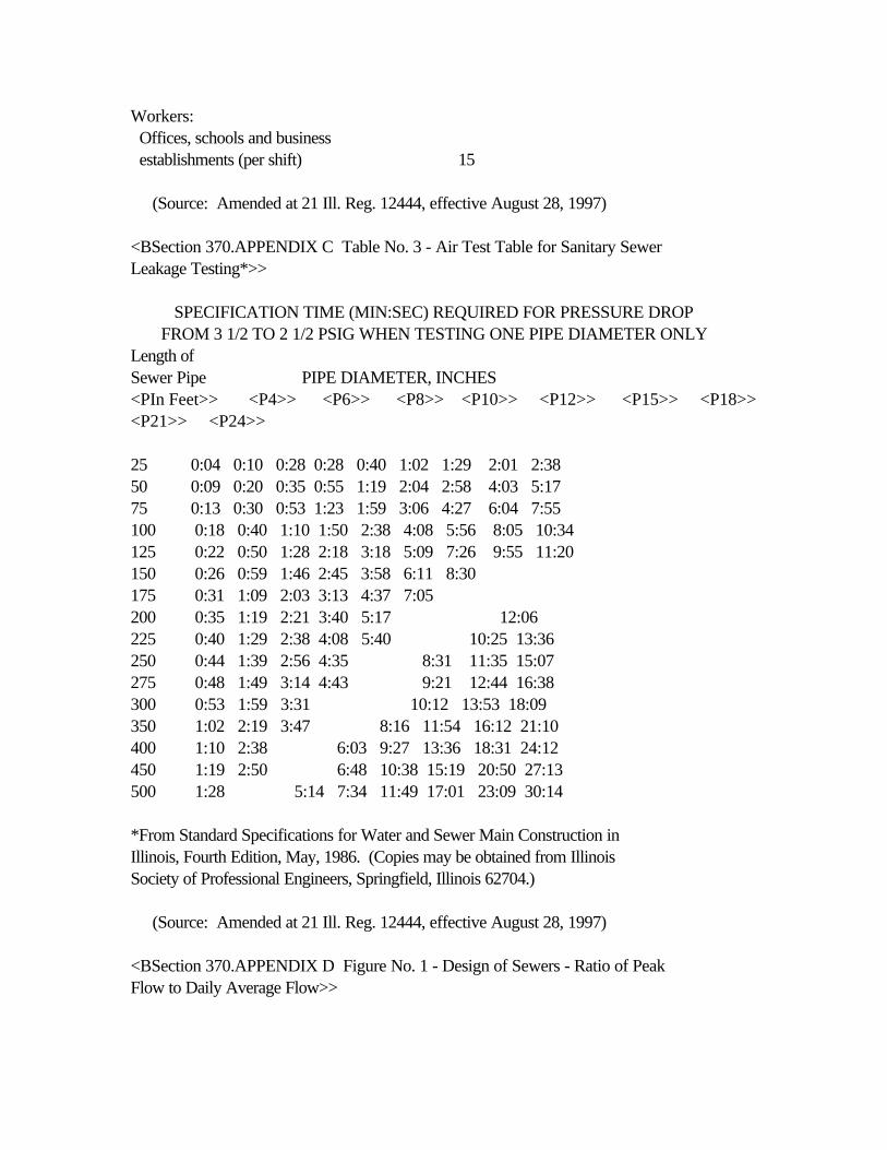
Workers: Offices, schools and business establishments (per shift) 15
(Source: Amended at 21 Ill. Reg. 12444, effective August 28, 1997)
<BSection 370.APPENDIX C Table No. 3 - Air Test Table for Sanitary SewerLeakage Testing*>>
SPECIFICATION TIME (MIN:SEC) REQUIRED FOR PRESSURE DROP FROM 3 1/2 TO 2 1/2 PSIG WHEN TESTING ONE PIPE DIAMETER ONLYLength ofSewer Pipe PIPE DIAMETER, INCHES<PIn Feet>> <P4>> <P6>> <P8>> <P10>> <P12>> <P15>> <P18>><P21>> <P24>>
25 0:04 0:10 0:28 0:28 0:40 1:02 1:29 2:01 2:3850 0:09 0:20 0:35 0:55 1:19 2:04 2:58 4:03 5:1775 0:13 0:30 0:53 1:23 1:59 3:06 4:27 6:04 7:55100 0:18 0:40 1:10 1:50 2:38 4:08 5:56 8:05 10:34125 0:22 0:50 1:28 2:18 3:18 5:09 7:26 9:55 11:20150 0:26 0:59 1:46 2:45 3:58 6:11 8:30175 0:31 1:09 2:03 3:13 4:37 7:05200 0:35 1:19 2:21 3:40 5:17 12:06225 0:40 1:29 2:38 4:08 5:40 10:25 13:36250 0:44 1:39 2:56 4:35 8:31 11:35 15:07275 0:48 1:49 3:14 4:43 9:21 12:44 16:38300 0:53 1:59 3:31 10:12 13:53 18:09350 1:02 2:19 3:47 8:16 11:54 16:12 21:10400 1:10 2:38 6:03 9:27 13:36 18:31 24:12450 1:19 2:50 6:48 10:38 15:19 20:50 27:13500 1:28 5:14 7:34 11:49 17:01 23:09 30:14
*From Standard Specifications for Water and Sewer Main Construction inIllinois, Fourth Edition, May, 1986. (Copies may be obtained from IllinoisSociety of Professional Engineers, Springfield, Illinois 62704.)
(Source: Amended at 21 Ill. Reg. 12444, effective August 28, 1997)
<BSection 370.APPENDIX D Figure No. 1 - Design of Sewers - Ratio of PeakFlow to Daily Average Flow>>
<BSection 370.APPENDIX E Figure No. 2 - Primary Settling>>
<BSection 370.APPENDIX F Figure No. 3 - B.O.D. Removal Single StageTrickling Filter Units Including Post Settling - No Recirculation Included>>
<BSection 370.APPENDIX G Figure No. 4 - Break Tank Sketch for Potable WaterSupply Protection>>
<BSection 370.APPENDIX H Old Section Numbers Referenced (Repealed)>>
(Source: Repealed at 21 Ill. Reg. 12444, effective August 28, 1997)


![TITLE 35: ENVIRONMENTAL PROTECTION · Environmental Protection Act [415 ILCS 5/9.1, 10 and 27]. SOURCE: Adopted as Chapter 2: Air Pollution, Rule 205: Organic Material Emission Standards](https://img.dokumen.tips/doc/110x75/5f87aca52618ed30f422df80/title-35-environmental-protection-environmental-protection-act-415-ilcs-591.jpg)


![TITLE 35: ENVIRONMENTAL PROTECTION 35: ENVIRONMENTAL PROTECTION . SUBTITLE A: GENERAL PROVISIONS . ... [415 ILCS 5/26 and 27] and Section 25-101 of the Electronic Commerce Security](https://img.dokumen.tips/doc/110x75/5b469c7f7f8b9a3a058b9ee9/title-35-environmental-35-environmental-protection-subtitle-a-general-provisions.jpg)


![National Environmental Protection Act 1984 [35 MIRC Ch 1] Legislation/Marshall_Islands/MH... · National Environmental Protection Act 1984 [35 MIRC Ch 1] 35 MIRC Ch 1 MARSHALL ISLANDS](https://img.dokumen.tips/doc/110x75/5c2d233009d3f2dd0b8b6f20/national-environmental-protection-act-1984-35-mirc-ch-1-legislationmarshallislandsmh.jpg)