Embed Size (px)
Citation preview

Pre-decisional — For Planning and Discussion Purposes Only
JPL D-37401 B January 30, 2007
Titan and Enceladus $1B Mission Feasibility Study Report Prepared for NASA’s Planetary Science Division Prepared By: Kim Reh Contributing Authors:
John Elliott Tom Spilker Ed Jorgensen John Spencer (Southwest Research Institute) Ralph Lorenz (The Johns Hopkins University, Applied Physics Laboratory)
ARCGSFCKSC
Approved By:
_________________________________ Kim Reh Dr. Ralph Lorenz Jet Propulsion Laboratory The Johns Hopkins University, Applied Study Manager Physics Laboratory Titan Science Lead _________________________________ Dr. John Spencer Southwest Research Institute Enceladus Science Lead

Titan and Enceladus Feasibility Study Report Table of Contents JPL D-37401 B
i Pre-decisional — For Planning and Discussion Purposes Only
The following members of an Expert Advisory and Review Board contributed to ensuring the consistency and quality of the study results through a comprehensive review and
advisory process and concur with the results herein. Name Title/Organization Concurrence
Gentry Lee Chief Engineer/JPL Planetary Flight Projects Office
Duncan MacPherson JPL Review Fellow
Glen Fountain NH Project Manager/JHU-APL
John Niehoff Sr. Research Engineer/SAIC
Bob Pappalardo Planetary Scientist/JPL
Torrence Johnson Chief Scientist/JPL

Titan and Enceladus Feasibility Study Report Table of Contents JPL D-37401 B
ii Pre-decisional — For Planning and Discussion Purposes Only
This page intentionally left blank

Titan and Enceladus Feasibility Study Report Table of Contents JPL D-37401 B
iii Pre-decisional — For Planning and Discussion Purposes Only
Table of Contents 1. EXECUTIVE SUMMARY.................................................................................................. 1-1
1.1 Study Objectives and Guidelines ............................................................................ 1-1 1.2 Relation to Cassini-Huygens, New Horizons and Juno .......................................... 1-1 1.3 Technical Approach ................................................................................................ 1-2 1.4 Costing Methodology.............................................................................................. 1-4 1.5 Cost Results ............................................................................................................ 1-5 1.6 Risk Assessment ..................................................................................................... 1-7 1.7 Science Value.......................................................................................................... 1-8 1.8 Feasibility Assessment and Conclusions ................................................................ 1-9
1.8.1 Titan Missions .......................................................................................... 1-10 1.8.2 Enceladus Missions .................................................................................. 1-10 1.8.3 Conclusions 1-11
1.9 Recommendations................................................................................................. 1-11 2. METHODOLOGY............................................................................................................... 2-1
2.1 Overview................................................................................................................. 2-1 2.2 Guidelines ............................................................................................................... 2-1 2.3 Team ....................................................................................................................... 2-1 2.4 Approach................................................................................................................. 2-2
2.4.1 Science and Measurement Objectives:....................................................... 2-2 2.4.2 Platforms and Mission Concepts................................................................ 2-2 2.4.3 Science Value............................................................................................. 2-4 2.4.4 Mission Cost............................................................................................... 2-4 2.4.5 Risk 2-4 2.4.6 Assessment of feasibility............................................................................ 2-5
3. TITAN SCIENCE AND PAYLOAD................................................................................... 3-1 3.1 The Importance of Titan – An Appealing and Broad Scientific Target ................. 3-1 3.2 Cassini Limitations and the Foundation for New Science...................................... 3-3 3.3 Titan Science Goals ................................................................................................ 3-3
3.3.1 Sources of Methane.................................................................................... 3-3 3.3.2 Condensation and Cloud Formation........................................................... 3-4 3.3.3 Conversion of Methane to Complex Organics in the Upper Atmosphere . 3-4 3.3.4 Aerosol Formation...................................................................................... 3-4 3.3.5 Surface Organic Inventory ......................................................................... 3-4 3.3.6 Geomorphological Processes and Transport of Organics .......................... 3-4 3.3.7 Surface Composition and Astrobiology ..................................................... 3-5
3.4 Rating and Down Selection of Mission Concepts .................................................. 3-5 3.5 Missions Rejected or Not Considered..................................................................... 3-6 3.6 Missions and Payload Studied ................................................................................ 3-7
3.6.1 Titan Orbiter 3-7 3.6.2 Aerobot 3-7 3.6.3 Long-Lived Lander .................................................................................... 3-8

Titan and Enceladus Feasibility Study Report Table of Contents JPL D-37401 B
iv Pre-decisional — For Planning and Discussion Purposes Only
3.6.4 ‘Huygens-Like’ Probe ................................................................................ 3-8 4. ENCELADUS SCIENCE AND PAYLOAD....................................................................... 4-1
4.1 The Importance of Enceladus ................................................................................. 4-1 4.2 Enceladus Science Goals ........................................................................................ 4-2
4.2.1 Tidal Heating.............................................................................................. 4-2 4.2.2 Interior Structure ........................................................................................ 4-2 4.2.3 Composition 4-3 4.2.4 Tectonism 4-3 4.2.5 Cryovolcanism ........................................................................................... 4-3 4.2.6 Surface Processes ....................................................................................... 4-4 4.2.7 Biological Potential .................................................................................... 4-4
4.3 Cassini Limitations ................................................................................................. 4-4 4.4 Rating and Down Selection of Mission Concepts .................................................. 4-5 4.5 Enceladus Plume Sample Return ............................................................................ 4-7 4.6 Saturn Orbiter with Multiple Enceladus Flybys ..................................................... 4-8 4.7 Single Enceladus Flyby: The Simplest Possible Mission ..................................... 4-10
5. MISSION ARCHITECTURE CONCEPTS......................................................................... 5-1 5.1 Overview................................................................................................................. 5-1
5.1.1 The Saturn System ..................................................................................... 5-1 5.1.2 Architectures Studied ................................................................................. 5-2
5.2 Travel to Saturn....................................................................................................... 5-2 5.3 Mission Option Trades............................................................................................ 5-4 5.4 Aerocapture............................................................................................................. 5-5 5.5 Mission Architectures ............................................................................................. 5-7
5.5.1 Titan Orbiter 5-7 5.5.2 Titan Aerobot ............................................................................................. 5-9 5.5.3 Titan Lander 5-11 5.5.4 Enceladus Plume Sample Return ............................................................. 5-12 5.5.5 Saturn Orbiter with Enceladus Flybys ..................................................... 5-14 5.5.6 Titan Entry Probe ..................................................................................... 5-16 5.5.7 Enceladus Single Flyby............................................................................ 5-17
6. FLIGHT SYSTEM CONCEPTS.......................................................................................... 6-1 6.1 Overview................................................................................................................. 6-1 6.2 SEP Stage Design ................................................................................................... 6-1 6.3 Titan Orbiter............................................................................................................ 6-3
6.3.1 TiPEx Orbiter Design................................................................................. 6-3 6.3.2 Cost Drivers 6-4 6.3.3 Titan Orbiter MEL ..................................................................................... 6-5
6.4 Titan Aerobot .......................................................................................................... 6-6 6.5 Titan Lander............................................................................................................ 6-3 6.6 Saturn Orbiter with Multiple Enceladus Flybys ..................................................... 6-3 6.7 Enceladus Plume Sample Return ............................................................................ 6-4

Titan and Enceladus Feasibility Study Report Table of Contents JPL D-37401 B
v Pre-decisional — For Planning and Discussion Purposes Only
6.7.1 Solar v. RPS Trade ..................................................................................... 6-4 6.8 Titan Atmospheric Probe ........................................................................................ 6-5 6.9 New Horizons-Based Enceladus Single Flyby ....................................................... 6-6 6.10 Flight System Cost Estimates ................................................................................. 6-6
7. GROUND SYSTEM ............................................................................................................ 7-1 7.1 Overview................................................................................................................. 7-1 7.2 Introduction............................................................................................................. 7-1 7.3 Common Elements.................................................................................................. 7-1 7.4 Unique Elements..................................................................................................... 7-3
7.4.1 Titan Orbiter 7-4 7.4.2 Titan Aerobot ............................................................................................. 7-4 7.4.3 Titan Lander 7-4 7.4.4 Enceladus Sample Return........................................................................... 7-5 7.4.5 Saturn Orbiter with Multiple Enceladus Fly-bys ....................................... 7-6 7.4.6 Enceladus Single Fly-By............................................................................ 7-6 7.4.7 Titan Atmospheric Probe ........................................................................... 7-6
7.5 Ground System Cost Summary............................................................................... 7-7 8. COST ASSESSMENT ......................................................................................................... 8-1
8.1 Cost Assessment Overview..................................................................................... 8-1 8.2 Cost Model Description .......................................................................................... 8-1 8.3 Cost Estimate Comparison...................................................................................... 8-2
9. SUMMARY ......................................................................................................................... 9-1 9.1 Findings................................................................................................................... 9-1 9.2 Robustness of Findings ........................................................................................... 9-1 9.3 Implications for Follow on Mission Studies........................................................... 9-2
APPENDIX A — FUNCTIONAL DESCRIPTION OF GROUND SYSTEM ..............................1 A-1 Tracking System ..................................................................................................... 9-1 A-2 Telemetry System .......................................................................................................2 A-3 Science Data Processing .............................................................................................2 A-4 Science Analysis .........................................................................................................2 A-5 Science and Mission Planning ....................................................................................2 A-6 Spacecraft Performance Analysis ...............................................................................2 A-7 Instrument Health and Performance Analysis ............................................................2 A-8 Sequencing..................................................................................................................3 A-9 Navigation...................................................................................................................3 A-10 Mission Control Team ................................................................................................3 A-11 Infrastructure support..................................................................................................3
Tables Table 2-1 Integrated Science and Engineering Team. ................................................................ 2-2 Table 2-2 Expert Review and Advisory Group........................................................................... 2-2 Table 3-1 Relative science value of Titan missions................................................................... 3-9 Table 3-2 Science Trace Matrix. .............................................................................................. 3-10

Titan and Enceladus Feasibility Study Report Table of Contents JPL D-37401 B
vi Pre-decisional — For Planning and Discussion Purposes Only
Table 4-1 Science Trace Matrix. ................................................................................................ 4-6 Table 4-2 Relative science value of Enceladus missions. .......................................................... 4-7 Table 5-1 Satellite characteristics. ............................................................................................. 5-1 Table 5-2 Summary of mission concepts studied....................................................................... 5-2 Table 5-3 Mission Option Trade. ............................................................................................... 5-4 Table 6-1: Design References. ................................................................................................... 6-1 Table 6-2 SEP Stage MELs........................................................................................................ 6-3 Table 6-3 TiPEx and Titan Orbiter MELs. ................................................................................ 6-6 Table 6-4 Titan Aerobot MEL. .................................................................................................. 6-3 Table 6-5 Titan Lander MEL. .................................................................................................... 6-3 Table 6-6 Saturn Orbiter MEL. .................................................................................................. 6-4 Table 6-7 Enceladus Plume Sample Return MEL. .................................................................... 6-4 Table 6-8 Titan Atmospheric Probe Carrier MEL. .................................................................... 6-5 Table 6-9 Titan Atmospheric Probe MEL.................................................................................. 6-6 Table 6-10 Flight System Cost Estimates. ................................................................................. 6-6 Table 7-1 Mission Options and Operations Drivers. .................................................................. 7-2 Table 7-2 Common DSN Profile................................................................................................. 7-3 Table 7-3 Titan Orbiter Details. .................................................................................................. 7-4 Table 7-4 Titan Aerobot Details.................................................................................................. 7-4 Table 7-5 Titan Lander Details. .................................................................................................. 7-5 Table 7-6 Enceladus Sample Return Details............................................................................... 7-5 Table 7-7 Saturn Orbiter with multiple Enceladus Fly-bys Details. ........................................... 7-6 Table 7-8 Enceladus Single Fly-by Details................................................................................. 7-6 Table 7-9 Titan Atmospheric Probe Details................................................................................ 7-7 Table 7-10 Mission Operations Cost Summary. ......................................................................... 7-8 Table 8-1 Cost Model Description. ............................................................................................. 8-2 Table 8-2 Reserves and Uncertainty model are consistent with maturity of study. Reserves are indicated by shading. ................................................................................................................... 8-3 Table 8-3 Total Mission Cost Comparison. ................................................................................ 8-5 Table 8-4 Titan Orbiter Cost Summary....................................................................................... 8-6 Table 8-5 Titan Aerobot Cost Summary. .................................................................................... 8-7 Table 8-6 Titan Lander Cost Summary....................................................................................... 8-8 Table 8-7 Saturn Orbiter – Enceladus Flyby............................................................................... 8-9 Table 8-8 Enceladus Sample Return. ........................................................................................ 8-10 Table 8-9 Titan Atmospheric Probe. ......................................................................................... 8-11 Table 8-10 Enceladus Single Fly-By ........................................................................................ 8-12
Figures Figure 1-1 Twenty-four missions initially examined................................................................. 1-3 Figure 1-2 Total Mission Cost. ................................................................................................... 1-5 Figure 1-3 Relative Risk Assessment for Titan and Enceladus Missions. Quantification indicates consequence and likelihood scores based on scale of 1-5; 1 being the lowest. ........................... 1-7 Figure 1-4 Titan Feasibility Assessment – Summary of Results. .............................................. 1-8 Figure 1-5 Enceladus Feasibility Assessment – Summary of Results. ...................................... 1-9 Figure 2-1 Structured Systematic Approach............................................................................... 2-3 Figure 2-2 Missions Selected for Feasibility Costing................................................................. 2-3 Figure 3-1 Titan is the 2nd largest satellite in the solar system. .................................................. 3-1 Figure 3-2 Titan is the most Earth-like body in the solar system. .............................................. 3-2 Figure 3-3 Titan’s landscape is being actively modified by Earth-Like processes. ................... 3-2 Figure 3-4 Titan has a very rich organic chemistry. .................................................................. 3-5 Figure 4-1 Global Cassini view of Enceladus (diameter 500 km). The active South Polar Region is ringed by a scalloped fracture zone and includes the four parallel “tiger stripe” fractures in its central region. .............................................................................................................................. 4-1

Titan and Enceladus Feasibility Study Report Table of Contents JPL D-37401 B
vii Pre-decisional — For Planning and Discussion Purposes Only
Figure 4-2 False-color image of the Enceladus south polar plume seen in forward-scattered light....................................................................................................................................................... 4-2 Figure 4-3 False-color image of 12-16 micron color temperatures on Enceladus, showing the heat radiation from the warm tiger stripes in the South Polar Region. Peak temperatures are much warmer, at least 145 K, than the low-resolution averages shown here. ............................. 4-2 Figure 4-4 Mass spectrum of the Enceladus plume obtained by Cassini in July 2005, showing mass peaks due to H2O, CO2, N2, CH4, and possibly C2H2 and C3H8.................................... 4-2 Figure 4-5 Near-infrared composite image of Enceladus showing the concentration of the 3.44 µm C-H stretch band (red) along the south polar tiger stripes..................................................... 4-3 Figure 4-6 An example of the wide variety of terrain types on Enceladus, including intense tectonic modification. The area shown is about 150 km across. ................................................ 4-3 Figure 4-7 Close-up of the south polar “tiger stripe” fissures that are the probable source of the plume, showing their blue color due to large ice grain sizes, and their enhanced thermal emission. The numbers are brightness temperatures in K, averaged over each 6x6 km mid-IR field of view. ................................................................................................................................ 4-4 Figure 4-8 The complex interaction between Enceladus and the E-ring, seen at high phase angles by Cassini.......................................................................................................................... 4-4 Figure 4-9 Tracks of comet grains captured in aerogel by the Stardust mission. ..................... 4-8 Figure 4-10 Comparison of resolution vs. Enceladus coverage expected for Cassini in the visible and thermal infrared through the end of the extended mission (dashed lines), to that possible with our proposed Saturn orbiter with multiple Enceladus flybys (solid lines). Major improvements in high-resolution coverage are possible.............................................................. 4-9 Figure 5-1 Saturn obliquity. ....................................................................................................... 5-1 Figure 5-2 Satellite orbits in the Saturn system. ........................................................................ 5-1 Figure 5-3 Mass delivered to Saturn approach and transfer time, parametric in trajectory type. 5-3 Figure 5-4 Example chemical trajectory to Saturn. ................................................................... 5-3 Figure 5-5 Example SEP trajectory to Saturn............................................................................ 5-3 Figure 5-6 Fundamental architecture of the aerocapture process. ............................................. 5-5 Figure 5-7 Science orbits for the Titan Orbiter mission concept. .............................................. 5-8 Figure 5-8 Example mission timeline for the Titan Orbiter mission concept. 2018 launch assumed........................................................................................................................................ 5-9 Figure 5-9 Notional Titan Aerobot atmospheric trajectory. .................................................... 5-10 Figure 5-10 Example mission timeline for the Titan Orbiter mission concept. 2018 launch assumed...................................................................................................................................... 5-11 Figure 5-11 Example mission timeline for the Titan Lander mission concept. 2018 launch assumed...................................................................................................................................... 5-12 Figure 5-12 Notional Enceladus sampling pass geometry....................................................... 5-14 Figure 5-13 Example mission timeline for the Enceladus Plume Sample Return concept. 2018 launch assumed. ......................................................................................................................... 5-14 Figure 5-14 Multiple flybys of Enceladus from the resonant orbit.......................................... 5-15 Figure 5-15 Example mission timeline for the Saturn Orbiter with Enceladus Fly-bys concept. 2018 launch assumed. ................................................................................................................ 5-15 Figure 5-16 Entry and data relay strategy for the Titan Entry Probe mission concept............ 5-17 Figure 5-17 Example mission timeline for the Titan Entry Probe mission concept. 2018 launch assumed...................................................................................................................................... 5-17 Figure 5-18 Example mission timeline for the Enceladus Single Flyby mission concept. 2016 launch to a direct JGA trajectory assumed. ............................................................................... 5-18 Figure 6-1 Solar Electric Propulsion Stage Design Concept Configuration.............................. 6-2 Figure 6-2 Orbiter Stowed Configuration – Design Concept. ................................................... 6-4 Figure 6-3 TiPEx Post-SEP Cruise Configuration – Design Concept. ...................................... 6-4 Figure 6-4 TiPEx Orbiter Science/Relay Configuration – Design Concept. ............................ 6-5 Figure 6-6 Montgolfiere Gondola Showing Notional Instrument Layout. ............................... 6-2 Figure 6-5 Aerial Vehicle Configuration. .................................................................................. 6-2

Titan and Enceladus Feasibility Study Report Table of Contents JPL D-37401 B
viii Pre-decisional — For Planning and Discussion Purposes Only
Figure 8-1 Total Mission Cost. ................................................................................................... 8-2 Figure 8-2 Mission Option Total Mission Cost with Range....................................................... 8-4 Figure 8-3 Mission Option Comparison. .................................................................................. 8-13 Figure 8-4 Elements for cost for New Horizons and Juno missions......................................... 8-13 Figure A-1 MOS GDS Diagram. ................................................................................................ 9-1

Titan and Enceladus Feasibility Study Report Table of Contents JPL D-37401 B
ix Pre-decisional — For Planning and Discussion Purposes Only
This page intentionally left blank

Titan and Enceladus Feasibility Study Report Executive Summary JPL D-37401 B
1-1 Pre-decisional — For Planning and Discussion Purposes Only
1. Executive Summary Two of Saturn’s icy moons, Titan and Enceladus, have been identified in NASA’s 2006 So-
lar System Exploration Roadmap and Science Mission Directorate (SMD) Science Plan as tar-gets warranting extensive investigation. Recent discoveries from the Cassini-Huygens mission have uncovered a Titan landscape and atmosphere rich in complex organics, as well as active hy-drocarbon rich plumes of water, hydrocarbons and other gases emanating from the south polar region of Enceladus. While many long held science questions have been answered by the Cas-sini-Huygens mission, many more have been raised. Within the context of scientific interest and recent Cassini-Huygens discoveries, NASA’s Planetary Science Division directed that JPL and a science team from the broader community determine the feasibility of conducting missions to Titan and Enceladus and to characterize the science return within a $1B FY06 cost cap.
The Study concludes that, at this time, no missions to Titan or Enceladus that achieve at least a moderate increase in understanding beyond Cassini-Huygens were found to fit within the cost cap of 1 billion dollars (FY’06).
1.1 Study Objectives and Guidelines NASA’s Planetary Science Division developed the objectives that drove this study as shown
below: • Determine feasibility of conducting missions to Titan or Enceladus within a $1B FY06
cost cap. • Characterize the science return achievable within a $1B FY06 cost cap. • Identify technologies required by the missions. In addition, the following guidelines were stipulated: • The cost cap includes the spacecraft and mission elements, including launch vehicle, sci-
ence instruments, radioactive power system, and reserve. The cost cap does not include technology development and/or maturation costs.
• Acceptable mission science return should enable at least a moderate advancement in sci-entific understanding beyond Cassini-Huygens.
• Mission concepts are to minimize use of new technology. • Foreign contributions should not be considered for this study. • Mission concepts are to assume launch opportunities no earlier than 2015.
1.2 Relation to Cassini-Huygens, New Horizons and Juno Cassini-Huygens is a >$3B Flagship class mission with a powerful instrument complement,
capable spacecraft and highly flexible mission design that enables it to visit many destinations in the Saturnian system. This mission sets high expectations for follow-up missions in the sub $1B category. Any new mission to Titan or Enceladus must be capable of enabling a significant advancement in scientific understanding.
While the Huygens (Titan entry probe) mission is complete, Cassini is still only two and a half years through its prime mission and an additional four years of productive observations at Titan and Enceladus are being planned. This study has attempted to anticipate likely results of this ongoing Cassini exploration although unanticipated surprises could influence the science objectives and mission concepts that were examined.

Titan and Enceladus Feasibility Study Report Executive Summary JPL D-37401 B
1-2 Pre-decisional — For Planning and Discussion Purposes Only
In contrast to Cassini-Huygens, there are two outer planet missions currently being implemented in the sub $1B cost range: New Horizons (NH) will explore a previously unexplored object (Pluto and KBOs); Jupiter Polar Orbiter (Juno) will apply a new technique from a new vantage point to a previously studied object (Jupiter). While these missions are much more constrained from a science perspective than Cassini-Huygens, they each provide a unique perspective on lower cost outer solar system missions and implementation approaches.
Experience as well as technical and cost data from Cassini-Huygens, NH and Juno have been applied to this study and also provide a benchmark against which to compare the results.
1.3 Technical Approach A small Science Definition and Engineering Team was formed to quickly evaluate and inte-
grate science objectives with mission concepts. Two science definition teams (one for Titan and one for Enceladus) were populated with members that NASA’s SMD Planetary Science Division (PSD) selected from the planetary community and more specifically the Outer Planet Assessment Group (OPAG). The balance of the study team was comprised of management, mission architec-ture, system engineering and cost analysis disciplines.
Given the short period of performance stipulated for this study (~2.5 months), the approach drew heavily upon existing information and was structured to limit scope as described below:
• Made use of results from previous Titan and Enceladus studies. • Applied experience and data from the Cassini-Huygens mission and two cost-capped
outer solar system missions, New Horizons and Juno. • Minimized new feasibility and cost assessment efforts by culling a small set of missions
with potential to meet study objectives from a broader set. To address the science guidelines for this study, science objectives were developed for Titan
and Enceladus investigations and traced to measurement requirements, which then led to the definition of applicable instruments. In concert with science definition, a broad set of candidate mission concepts were identified. To address the cost cap (<$1B FY06), costs for key mission elements, less payload and science activities, that are typically well defined (e.g., launch vehi-cles, power sources, propulsion systems, LA/NEPA, spacecraft bus, mission operations….) were estimated to provide an understanding of the practical lower limit of mission cost and to establish anticipated budget allocations for science and payload. Twenty-four (24) candidate science mis-sions were identified as shown in Figure 1-1. As stated earlier, the scope and schedule for this study did not allow the development of detailed conceptual designs and cost estimates for each of the 24 options so a feasibility down-selection (based on science and cost) was used to identify a smaller set of missions for further study. Of the 24 candidate missions identified, eleven (11) missions were ruled out because they were judged likely to exceed the cost cap by a wide mar-gin. This assessment was based on previous results from studies involving similar complex multi-element architectures. Two (2) were ruled out because they were judged to fall short of the science guideline by a wide margin. An additional four (4) were ruled out because they were judged as unlikely to meet both the cost cap and the science guideline. There remained a total of seven (7) missions that showed promise in meeting the science or cost guidelines that were se-lected for additional scrutiny. Five of these appeared to meet the science guideline and were ini-tially judged to have a possibility of meeting the cost cap. The remaining two appeared more likely to meet the cost cap, but were judged by the science team not to meet the science guide-line.

Titan and Enceladus Feasibility Study Report Executive Summary JPL D-37401 B
1-3 Pre-decisional — For Planning and Discussion Purposes Only
Moon Orbiters with or without In
Situ element
TITAN Orbiter+Lander
Titan Orbiter+Aerobot
Saturn Orbiter with or without In Situ or Sample Return element
Sat Orbiter + TITAN Lander
Sat Orbiter+TITAN Aerobot
Sat Orbiter + TITAN Atm SR
Single Fly-By with or without In Situ or Sample Return
element
FB S/C + Titan Lander
FB S/C + TITAN Aerobot
TITAN Atm SR
In Situ only
TITAN Orbiter
Sat Orbiter Multiple TITAN Fly-bys
Sat Orbiter Multiple ENC Fly-bys
ENCELADUS Plume SR
Single TITAN fly-by
TITAN Lander
TITAN Aerobot
FB S/C + TITAN Atm Probe
Titan and Enceladus Missions
Saturn Orbiter;TITAN & ENC Cycler
multiple complex architectural elements; large propulsion delta-V – high cost
Potentially valuable science, large propulsion delta-V to reach surface - high cost
science return not compelling even with new instruments compared to Cassini -low science return
insufficient science increment beyond Huygens, low science return
multiple complex architectural elements – high cost
only a few seconds of unique science prior to impact, not compelling – low science return
ENCELADUS Orbiter delta-v too costly even with Titan aerocapture into Saturn orbit – high cost
new instrumentation could provide moderate science return beyond Cassini
Potential value of science return is very high, mission is high risk: >10 km/s sample capture speeds and long duration >18 years
Long dwell at Titan with new instrumentation enables complete and improved mapping of surface and upper atmosphere
More FBs at Titan than at ENC. Insufficient increase in understanding beyond Cassini even with improved instrumentation – low science return
Fewer FBs at ENC than at Titan. Insufficient increase in understanding beyond Cassini even with improved instrumentation – low science return
new instrumentation enables surface chemistry; RPS enables long term MET and Seismic monitoring (new science) – multiple battery landers not considered due to probable high cost. Single battery lander provides insufficient science.
Provides no advance over Cassini - low science return
multiple complex architectural elements – high cost
new instrumentation for chemistry, structure and long term meteorological & seismological monitoring (new science) – no surface sampling
ENCELADUS Lander
multiple complex architectural elements – high cost
ENC Orbiter + Lander
multiple complex architectural elements – high cost
Sat Orbiter + ENC Plume SR
FB S/C + ENC Hard Lander
Single ENCELADUS fly-by
multiple complex architectural elements – high cost
Limited atmospheric sample and return to earth - low science return
multiple complex architectural elements – high cost
Sample integrity not assured (loss of volatiles, polymerization during sampling process); does not sample diverse locations, multiple complex architectural elements – high costmultiple complex architectural elements – high cost
FB S/C + ENC Inst Impactor
multiple complex architectural elements – high cost
Core Titan Missions Core Enceladus Missions
1
2
3
4
5
6
7
8
9
10
11
12
13
14
15
16
17
18
19
20
21
22
23
24
ARCHITECTURAL ELEMENTS MISSION SELECTION RATIONALE
Figure 1-1 Twenty-four missions initially examined.

Titan and Enceladus Feasibility Study Report Executive Summary JPL D-37401 B
1-4 Pre-decisional — For Planning and Discussion Purposes Only
The resulting set of seven (7) missions considered for feasibility costing included four Titan missions and three Enceladus missions as described below.
1) Titan Orbiter: aerocapture and braking into Titan’s atmosphere; 1500 km orbit; 2-year global mapping and atm. measurements.
2) Titan Aerobot: direct entry into Titan; Montgolfiere hot air balloon at 10 km altitude; 1-year in situ science survey of atmosphere and surface.
3) Titan Lander: direct entry into Titan; Huygens style parachute soft landing; 3-month Viking-like surface sampling and imaging followed by 21-month seismic and meteorological monitoring
4) Titan Atmospheric Probe: simple fly-by s/c for Huygens-Like atmospheric probe delivery and comm. relay; 4-8 hr encounter. Note: science return is below guideline due to high bar set by Cassini-Huygens.
5) Saturn Orbiter/Multiple Enceladus Fly-Bys: aerocapture into Saturn’s orbit using Titan’s atmosphere; targeted plume and global science via >30 Fly-Bys of Enceladus over 2-year period.
6) Enceladus Plume Sample Return: Stardust-like in situ sample capture >10 km/s; remote sensing and in situ measurements; Earth free-return trajectory
7) Enceladus Single Fly-By: NH-like mission using NH spacecraft with new but similar payload, single fly-by science return. Note: science return is below guideline due to high bar set by Cassini’s campaign of Enceladus fly-bys.
1.4 Costing Methodology A conceptual design was developed as a costing baseline for each of the 7 selected missions
based on a flow down of science requirements and application of existing design information from previous studies and ongoing missions. This effort resulted in quantified technical parameters for each mission that were used as input to a comprehensive outer planet mission cost model. Since the Enceladus Single Fly-By mission (#7 above) was heavily based on use of the NH flight system, its cost was uniquely derived using actual costs from the NH mission directly. The outer planet cost model includes a mix of parametric cost models, analogies to previ-ous/ongoing missions as well as historic wrap factors and provides an estimate of Total Mission Cost (TMC). JPL’s work breakdown structure (WBS) and WBS dictionary were applied to en-sure that all mission cost elements for the entire life cycle were adequately captured.
All critical parameters as well as an assessment of reserves were entered into the cost model to derive Total Mission Cost for each concept. In addition, an uncertainty model was developed to account for immaturity of mission concepts at this early stage of definition and limitations of the costing model. These uncertainty estimates were then added to the TMC to provide a quanti-fication of the variability of expected costs for each mission. Finally, the costing results were examined by the team as well as external independent reviewers to ensure reasonableness of re-sults.

Titan and Enceladus Feasibility Study Report Executive Summary JPL D-37401 B
1-5 Pre-decisional — For Planning and Discussion Purposes Only
1.5 Cost Results The estimated total mission costs and associated uncertainty for the set of seven missions are
shown in Figure 1-2. Note that the total mission cost (current best estimate plus reserves) for each of the missions is indicated in the Figure by the red rectangular symbol and the uncertainty around each estimate is indicated by the vertical bar. Due to the low level of maturity of these mission concepts, the required reserves are higher and uncertainty is broader than what would typically be carried at the beginning of a project’s Phase B, Preliminary Design.
800
1000
1200
1400
1600
1800
2000
Titan Orbiter Titan Aerobot Titan Lander Saturn OrbiterEnc. Fly-by
Enceladus SR Titan Atm.Probe
EnceladusSingle Fly-by
$FY0
6M
TMC
- Technology Liens not included- Contingency applied to account for uncertainty at this early stage- Costs of Titan & Saturn Orbiter missions are higher than in-situ and sample return missions due to more data-intensive payload suites needed to acquire science beyond Cassini. This leads to more capable instruments, higher data rates and a more massive, higher power design.
Science value below guideline
Design Maturity Reserves
CBE Cost
LV + LV Capability MarginUncertainty
Range associated with cost uncertainty and technical implementationvariation
Subfactors ReservesCost RiskTMC
Figure 1-2 Total Mission Cost.
From Figure 1-2 it can be seen that relative costs of the Titan Orbiter and Saturn Orbiter mis-sions are higher than costs for the other missions. These missions are driven by the more data-intensive instrument suites needed to acquire science results moderately beyond Cassini-Huygens. The more data intensive instruments lead to higher data rates and more massive, higher power designs for the orbiting mission concepts; hence higher cost. Note that the risks associated with orbiter missions are likely to be moderate-to-low because the environment and implementation aspects of planetary orbiters are better understood based on a large body of ex-perience. Therefore, somewhat lower levels of reserves for cost risk are included in the TMC as well as smaller relative uncertainty estimates.
Titan in situ aerobot and lander concepts take full advantage of the favorable Titan environ-ment to minimize mass and achieve valuable science results beyond Cassini-Huygens with mod-est instrumentation. These concepts incorporate a science payload with relatively low power and data rate demands resulting in lower relative mission cost. These missions are generally per-

Titan and Enceladus Feasibility Study Report Executive Summary JPL D-37401 B
1-6 Pre-decisional — For Planning and Discussion Purposes Only
ceived as moderate-to-high risk due to the uniqueness and uncertainty of the environment during the entry, descent and landing phases and the minimal experience of implementing in situ plane-tary missions. Therefore their estimates are characterized by higher reserves and relative uncer-tainty bars.
The Enceladus Plume Sample Return concept includes a minimal instrument suite and Star-dust-type sample capture and return system. The spacecraft travels on a SEP assisted ballistic trajectory to achieve a single pass through the Enceladus plume and then follows a free-return ballistic trajectory to transfer the collected samples to earth. While the mission life is long, the total mission costs are relatively low because the spacecraft and instrument configuration are minimal. By its nature, this mission has a high potential science value, given that the entire mis-sion completes successfully. However due to the high particle capture velocities at Enceladus (>10 km/s compared to ~6 km/s for Stardust) and long lifetime (>18 years), this concept has a high level of perceived risk associated with its ability to yield science results.
Even though the Titan Atmospheric Probe and Enceladus Single Fly-By missions fail the sci-ence guidelines for this study by a significant margin, they were studied further because it was believed that they provide a perspective on the cost floor for missions to Titan or Enceladus. Other than the shorter interplanetary transfer time, the Enceladus Single Fly-By mission is very similar to the New Horizons Pluto mission in that it makes a single relatively high speed pass by Enceladus for a very short encounter. The mission cost assumes a highly constrained capability driven development similar to New Horizons (its cost is only slightly higher than the NH mis-sion) and therefore has lower uncertainty relative to the other missions studied. The Titan At-mospheric Probe mission is scaled down dramatically from Cassini-Huygens in that it uses a very simple fly-by spacecraft to deliver and provide data relay for a Huygens-like probe that would achieve a several-hour descent in Titan’s atmosphere. Since this mission does not include an orbiter and the probe is limited to atmospheric science only, the cost is low relative to the other candidates. Both missions are expected to have a relatively low risk since they are based on missions and systems that have already been demonstrated. The assessment of these options demonstrates that the cost of flying a mission to Titan or Enceladus, even with unacceptable sci-ence, is ~ $1B.
Of the seven (7) missions costed for feasibility, the Enceladus Single Fly-By mission margin-ally meets the cost cap but falls well below the science guidelines for this study because of the high bar set by Cassini-Huygens performance for similar scenarios. Even with improved instru-mentation it was determined that these missions would not achieve a science floor beyond Cas-sini-Huygens that would be worth the required $1B or greater investment. The Titan Atmos-phere Probe comes close to meeting the cost cap, but was judged to fall short of the science guideline by a wide margin. The remaining 5 missions do meet the science guidelines as stated earlier; however, they exceed the cost cap significantly because they require the implementation of more complex architectures.
It is important to acknowledge that while the TMC estimates from this study do consider de-velopment risk in the reserves model, they do not account for mitigation of all risks. Costs for technology maturation through flight readiness (NASA definition of TRL6) and for a small sub-set of development tasks that could not be accurately quantified within the limited timeframe and scope of this study have been identified as liens against the estimated costs.

Titan and Enceladus Feasibility Study Report Executive Summary JPL D-37401 B
1-7 Pre-decisional — For Planning and Discussion Purposes Only
1.6 Risk Assessment Risk plays a key role in performing an analysis of alternatives. Most development risks were
addressed and their mitigation costs included in the cost reserve element. However cost associ-ated with key mission risks – which encompass the risk associated with achieving the specified science return – and a small set of development risks that could not be adequately estimated within the scope of this study were considered as an independent variable in performing the overall assessment of whether a credible $1B mission to Titan or Enceladus could be imple-mented. These risks and the magnitude of their potential impact (uncosted liens) are shown in Figure 1-3. A relative ranking of these risks based on consequence and likelihood scoring (ref: JPL D-15951, “Risk Management Handbook for JPL Projects,” which is compliant with NPG 7120.5C, NASA Program and Project Management Processes and Requirements) indicates that the Enceladus Sample Return mission has the highest overall perceived risk to mission success due to challenges associated with hypervelocity sample capture and extremely long mission life. The Titan Orbiter and Saturn Orbiter missions have medium risk primarily due to uncertainty in flight readiness of the aerocapture technology. The Titan Lander and Aerobot missions have me-dium risk associated with uncertainty in entry, descent and landing performance in a new envi-ronment.
Significant Risks Mitigation Approach
Cost impact
H:C>$50M
M:$10M<C<$50M
L:C<$10
Tita
n O
rbite
r
Tita
n A
erob
ot
Tita
n La
nder
Tita
n A
tmos
pher
ic P
robe
Ence
ladu
s Sa
mpl
e R
etur
n
Satu
rn O
rbite
r w M
ultip
le
Enc
FBs
Sing
le E
ncel
adus
FB
EDL proves more challenging than anticipated
EDL simulation, modeling and test M 3,3 3,2 1,1
Aerocapture technology not validated Flight validation H 4,3 4,3
Materials and systems don't meet cryogenic env rqmts
Low temperature materials and systems technology L 2,3 2,3
Existing sample acq handling inadequate for mission need
In situ instrument and sample handling technology M 3,2
Plume does not exist at time of arrival
Plume analysis and modeling using Cassini data L 5,1 3,1 4,1
Plume particle impact hazard has high uncertainty S/C Armor L 3,3 3,3 1,3
Existing high speed particle capture capability not applicable
Sample capture and test technology H 5,5
Current capability not qualified for >18 year mission life
Reliability analysis, life testing, robust design M 5, 5
Existing curation facilities not adequate for sample return Curation facility H 5,1
med med med low high med lowOverall Mission Risk Rating Figure 1-3 Relative Risk Assessment for Titan and Enceladus Missions. Quantification indicates consequence and likelihood scores based on scale of 1-5; 1 being the lowest.
The Titan Atmospheric Probe and Single Enceladus Fly-By missions have the lowest risk be-cause they are based on missions and systems that have already been demonstrated in flight and require no additional technology maturation. Clearly, a more thorough assessment of these risks

Titan and Enceladus Feasibility Study Report Executive Summary JPL D-37401 B
1-8 Pre-decisional — For Planning and Discussion Purposes Only
and associated mitigation costs will be needed to understand the full investment required for im-plementation of each mission.
1.7 Science Value Overall results of the study are summarized in Figures 1-4 and 1-5 which illustrate a relative
measure of science value for the 24 Titan and Enceladus missions. The Science Rating (Y-axis) was established by the SDTs by evaluating the various mission concepts and assessing their abil-ity to address the various science objectives. For each mission the team estimated whether it would provide a small, large, or very large increment in scientific understanding of each objec-tive, beyond Cassini. Then, each mission concept was assigned an overall numerical rating from 1 to 10, to reflect how well that mission would advance the overall knowledge of Titan or Enceladus. The overall rating differed slightly from the average rating in the various science categories, reflecting the fact that not all science goals are of comparable importance. These rat-ings were influenced not only by the past results of Cassini-Huygens but also by the projected future results from the continuing Cassini mission. The approach was simplistic and linear but did yield a reasonable measure of the placement of these missions relative to one another (this summary was not intended to rate Titan missions relative to Enceladus missions).
1 Sci
ence
Rat
ing
2,3Mission Cost ($B FY06)
0 1.0
The study found no Missions at
<$1B that represent a suffic
ient
increase in understanding
beyond Cassini-Huygens
NF Small Flagship Flagship2.0 3.0
Titan Orbiter
Titan Orb+Aerobot*
Sat Orb+Titan Atm SR
FB s/c+Titan Aerobotor Lander
Titan LanderTitan Aerobot
FB s/c w/Titan Atm SR
Sat Orb+Multiple Titan FB
Single Titan FB
FB s/c+Titan Atm Probe (Huygens-like)
Sat Orb+T/E Cycler
Titan Orb+Lander*
Incr
ease
in U
nder
stan
ding
Bey
ond
Cas
sini
-Huy
gens
Low
to M
oder
ate
Mod
erat
eto
Hig
h
NH Juno CassiniCost References
Sat Orb+Titan Lander
Sat Orb+Titan Aerobot
Titan Orb+Lander+Aerobot*Feasibility EnvelopeFeasibility Envelope
4.0
1) Nominal science return shown; uncertainty varies among missions2) Mission cost estimate plus range of uncertainty shown3) Relative costs and uncertainties for missions not assessed by this study are
estimated based on technical results of previous studies4) Technology development and mission risk liens are not included in cost
Estimated Mission CostCost UncertaintyLow RiskMedium RiskHigh Risk
*Cos
t est
imat
ed u
sing
sam
e m
odel
sub
sequ
ent t
o st
udy
com
plet
ion
Figure 1-4 Titan Feasibility Assessment – Summary of Results.

Titan and Enceladus Feasibility Study Report Executive Summary JPL D-37401 B
1-9 Pre-decisional — For Planning and Discussion Purposes Only
1 Sci
ence
Rat
ing
2,3Mission Cost ($B FY06)
0 1.0
The study fo
und no Missions at
<$1B that represent a su
fficient
increase in understanding
beyond Cassini-H
uygens
NF Small Flagship Flagship2.0 3.0
Enc Orb+Lander
Enc Orb
Enc Lander
Sat Orb+Enc SR
FB s/c+Enc Inst Impactor
Sat Orb+Mult E FBFB s/c+Enc Hard Lander
Single Enc FB
Incr
ease
in U
nder
stan
ding
Bey
ond
Cas
sini
-Huy
gens
Low
to M
oder
ate
Mod
erat
eto
Hig
h
NH Juno CassiniCost References
Sat Orb T/E Cycler
Enceladus SR
Feasibility EnvelopeFeasibility Envelope
4.0Flagship
1) Nominal science return shown; uncertainty varies among missions2) Mission cost estimate plus range of uncertainty shown3) Relative costs and uncertainties for missions not assessed by this study are
estimated based on technical results of previous studies4) Technology development and mission risk liens are not included in cost
Estimated Mission CostCost UncertaintyLow RiskMedium RiskHigh Risk
Figure 1-5 Enceladus Feasibility Assessment – Summary of Results.
Quantification of Mission Cost and associated uncertainty ranges (x-axis) for options not spe-cifically costed as part of this study were derived from information available from previous stud-ies and ongoing missions. For missions costed specifically as part of this study (indicated by Bolded text and Bold outlined rectangle), values for cost estimates and uncertainty ranges were generated using the outer planet costing model and actual costs from the NH mission.
As shown in the figures, five of the seven missions that were studied in detail were ranked sufficient in science value at small flagship class cost (following the classification scheme used by the Solar System Exploration Roadmap of 2006) and the remaining two were ranked insuffi-cient in science value at New Frontiers class cost. Some of the missions rejected early appear to have high cost but low value. Missions that were ranked highest in science value were judged to fall within the Flagship class category.
1.8 Feasibility Assessment and Conclusions The objective of the study was to determine the feasibility of implementing a mission to ei-
ther Titan or Enceladus that would fit within a $1B FY06 cost cap and yield sufficient advance-ment in science understanding beyond that obtained by Cassini-Huygens. To accomplish that, information developed in prior sections on mission science value, cost and risk was synthesized to determine if there are any missions that meet the science guideline and cost cap. In addition, an examination of the underlying cost drivers for science value, cost and risk was undertaken as well as an assessment of robustness of results.

Titan and Enceladus Feasibility Study Report Executive Summary JPL D-37401 B
1-10 Pre-decisional — For Planning and Discussion Purposes Only
1.8.1 Titan Missions In Figure 1-4, the science value rating is plotted against cost for the 14 Titan missions stud-
ied. For the four for which detailed costing was performed, an assessment of mission risk (taken from Figure 1-3) is shown. Several conclusions can be drawn from these results:
1. None of the Titan missions studied fall in the quadrant shaded green which represents missions that are less than $1B in cost with sufficient science value. In fact there are no missions that are close to the sufficient range.
2. Two missions – Single Titan FB and FB s/c with Titan Atmospheric Probe – plot either in the lower left quadrant or close to it. These missions do not meet the science guideline although at lease one of them meets the cost cap.
3. Three missions – Titan Orbiter, Titan Aerobot and Titan Lander – meet the science guideline but have cost estimates in the range of $1.3B to $1.8B. These have been char-acterized as small Flagship missions following the classification scheme used by the So-lar System Exploration Roadmap of 2006. It is important to note that there is a signifi-cant step in cost and science capability at around $1.3B or greater (there is not a continuum of other mission options in that range from $0.8B to $1.3B).
4. Three other missions, all involving multiple architectural elements and science platforms – Titan Orbiter plus Lander plus Aerobot, Titan Orbiter plus Aerobot, and Titan Orbiter plus Lander – have very high science value but at costs in the $2.5B and greater range. These missions were not examined in as much detail as those discussed earlier and there-fore their cost and science value are somewhat less defined. These have been character-ized as Flagship missions again following the Roadmap scheme discussed above.
1.8.2 Enceladus Missions In Figure 1-5, the science value rating is plotted against cost for the 10 Enceladus missions
studied. For the three for which detailed costing was performed, an assessment of mission risk (taken from Figure 1-3) is shown. Several conclusions can be drawn from these results:
1. None of the missions studied fall in the quadrant shaded green which represents missions that are less than $1B in cost with sufficient science value. In fact there are no missions that are close to the sufficient range.
2. One mission – Single Enc FB – appears in the lower left quadrant. This mission meets the cost cap but falls short of sufficient science value.
3. Two missions – Saturn Orbiter with Multiple Enceladus Fly-Bys (FB) and Enceladus Sample Return (SR) – meet the science guideline with a significant margin but have costs in the $1.3B to $1.8B range. One of these missions, Enceladus Sample Return, is also considered to be of high risk with two major risk elements as shown in Figure 1-3. These missions are in the small Flagship category as defined above. As with the Titan missions, there is a significant step in cost and science capability at around $1.3B or greater.
4. Several missions have been identified with still higher science value but also significantly higher costs. The highest value science missions are the Enceladus Orbiter and the Enceladus Orbiter plus Lander. These missions were not examined in as much detail as those discussed earlier and therefore their cost and science value are somewhat less de-fined. These have been characterized as Flagship missions again following the Roadmap scheme discussed above.

Titan and Enceladus Feasibility Study Report Executive Summary JPL D-37401 B
1-11 Pre-decisional — For Planning and Discussion Purposes Only
1.8.3 Conclusions As a result, the following conclusions were made: 1. No missions to Titan or Enceladus, that achieve a sufficient advancement in scientific un-
derstanding beyond Cassini-Huygens, were found to fit within the cost cap of $1.0 billion dollars (FY’06).
2. Three of the missions studied have the potential to meet the cost cap but fall below the science guidelines established for this study. a. Single Fly-By of Enceladus b. Single Fly-By of Titan c. Single Fly-By of Titan with Atmospheric entry Probe (Huygens-like)
3. Even the lowest cost mission studied, without the cost of science payload, has a minimum expected cost of ~$800M making it highly unlikely that unexplored approaches exist that achieve sufficient science value for $1B.
4. All Titan and Enceladus missions that meet science guidelines require some maturation of existing technology for flight readiness
1.9 Recommendations The following recommendations are provided: 1. Results of this study should be considered as a stepping off point for follow-on NASA
Studies. 2. Maturation of technologies necessary to implement Titan and Enceladus concepts should
be considered for programmatic funding. For example: a. Aerocapture (flight validation) b. Aerial mobility (aerobots, onboard autonomy) c. Low temperature materials and systems d. Sample acquisition and organic analysis instrumentation e. High speed sample capture (>10 km/s) f. Returned sampling handling (biological potential)

Titan and Enceladus Feasibility Study Report Methodology JPL D-37401 B
2-1 Pre-decisional — For Planning and Discussion Purposes Only
2. Methodology
2.1 Overview The objective of this study was to deter-
mine the feasibility of conducting missions to Titan and Enceladus and characterize the sci-ence return within a $1B FY06 cost cap. A key aspect of the approach was to leverage from Cassini-Huygens results and achieve ad-vancement in scientific understanding beyond the Cassini-Huygens mission. Since the dura-tion of the study was limited to 2.5 months, the team built upon previous Titan study re-sults and emerging Enceladus assessments. As a result, the mission definitions are con-ceptual and the total mission cost is parametric in nature.
2.2 Guidelines Key guidelines established for the study
include: 1. The cost cap includes the spacecraft and
mission elements, including launch vehi-cle, science instruments, radioisotope power system, and reserve. The cost cap does not include technology development and/or maturation costs.
2. Acceptable mission science return should enable at least a moderate advancement in scientific understanding beyond Cassini-Huygens.
3. Mission concepts are to minimize use of new technology
4. Foreign contributions should not be con-sidered for this study
5. Mission concepts are to assume launch opportunities no earlier than 2015
6. Planetary Protection (PP) category: a. Orbiters, category 2; "Of significant
interest relative to the process of chemical evolution but only a remote chance that contamination by space-craft could jeopardize future explora-tion."
b. Aerobots and Landers, category 2 c. Sample Return, Category 2 (uncosted
lien for Category 3-outbound / Cate-gory 5-inbound)
2.3 Team An integrated science and engineering
team was formed to perform this study. This team included a Titan Science Definition Team (SDT) led by Ralph Lorenz, an Encela-dus Science Definition Team led by John Spencer and an Engineering team led by Kim Reh (overall study lead). NASA SMD-PSD chose SDT members from the outer planet community, namely Outer Planet Assessment Group (OPAG). JPL (with the concurrence of PSD) augmented each SDT with a cognizant study scientist. Table 2-1 provides a listing of team members and their organizations.
An independent review and advisory group was formed for the purpose of ensuring thoroughness and quality of results. Members of that group included recognized experts in key disciplines from JPL, APL and SAIC as shown in Table 2-2.

Titan and Enceladus Feasibility Study Report Methodology JPL D-37401 B
2-2 Pre-decisional — For Planning and Discussion Purposes Only
Table 2-1 Integrated Science and Engineering Team.
Titan SDT Ralph Lorenz (lead) APL Elizabeth Turtle APL Frank Crary SwRI Hunter Waite SwRI Eric Wilson JPL Rosaly Lopes* JPL Enceladus SDT John Spencer (lead) SwRI Andy Ingersoll CalTech Amy Simon-Miller GSFC Bill McKinnon, WUStL Chris McKay ARC Rich Terrile* JPL Engineering Team Kim Reh (Study lead), JPL JPL Ed Jorgensen — Cost engineering, data input and analysis
JPL
Andrew Dantzler — Cost engineering, data input and analysis
APL
Tom Spilker — Mission Architecture JPL John Elliott — Flight System Engineering JPL Theresa Kowalkowski — Mission Design JPL Greg Welz — MOS, GDS, DSN utilization JPL Navid Dehghani — MOS, GDS, DSN utilization
JPL
Norm Beck — LV services KSC * denotes JPL augmentation to SDT with concurrence from NASA SMD PSD
Table 2-2 Expert Review and Advisory Group. Name Function/Org Glen Fountain NH Project Manager/John Hopkins
University-Applied Physics Labo-ratory (APL)
Gentry Lee Chief Engineer/Jet Propulsion Laboratory (JPL) Planetary Flight Projects Office
Duncan MacPherson
JPL Planetary Flight Projects Of-fice
John Niehoff Senior Research Engi-neer/Science Applications Interna-tional Group (SAIC)
Bob Pap-palardo
Planetary Scientist/JPL Science Division
2.4 Approach A structured approach was taken to
identify Titan and Enceladus mission concepts and to systematically evaluate whether they in fact satisfied the cost cap and science guidelines. This approach is illustrated in Figure 2-1. 2.4.1 Science and Measurement
Objectives: For each moon a set of science objectives
was developed by the Science Teams. These objectives were guided by the more general science goals for solar system exploration that have been formulated by the NRC’s Decadal Survey and the 2006 Solar System Explora-tion Road Map team. For each science objec-tive, measurement objectives were defined and used to establish the types of instruments and operational scenarios that would be needed to implement those objectives. This process established the flow down of science requirements. 2.4.2 Platforms and Mission Concepts
Given the science requirements, instru-ment accommodation needs, and cost con-straints, a number of potential platforms for carrying out those measurements were consid-ered. These included Saturn orbiters, moon orbiters, moon probes, landers and balloons and a hypervelocity sample return concept. Mission concepts were then devised in which one or more of the platforms were employed as part of an integrated mission to carry out the required operational scenario at either Ti-tan or Enceladus. A high-level description of each concept, including science scenarios and data flows, was developed in order to charac-terize the science value, cost and risk of each concept. The set of mission concepts consid-ered in this study appear in Figure 2-2. Those that were determined on the basis of Science Value or Cost to be the best candidates for a future $1B class Titan or Enceladus mission are highlighted in light green (Figure 2-2) and are described more thoroughly in Sections 5 and 6.

Titan and Enceladus Feasibility Study Report Methodology JPL D-37401 B
2-3 Pre-decisional — For Planning and Discussion Purposes Only
Parametric Cost Model
Anticipated costs for msn
elements
Science Objectives and Measurements
InstrumentsScience
Scenarios/Data Flow
Identify Candidate Missions
Cost
Feasible Mission Concepts Technology
Science Characterization
Cost Drivers
mission inputs
Mission Definition
Cost/Risk Assessment
Study Results
Risk
Work Breakdown Structure
Payload System
Flight System
Launch System
Msn Ops Sys
Science & EPO
Msn Sys Design
Safety and MA
Mgmt & Sys Eng
Cost Baseline Definition
Previous study results & recent
experienceScience Value
Sele
ct s
mal
l Set
of
Prom
isin
g M
issi
ons
Figure 2-1 Structured Systematic Approach.
Target In Space Flight System In Situ Flight System Sample Return System Cost Science
1 Titan Lander2 Enceladus Lander3 Titan Aerobot4 Titan5 Enceladus
6 Titan Lander7 Titan Aerobot8 Titan Atmospheric sampler Earth entry capsule9 Enceladus Plume sampler Earth entry capsule
10 Titan/Enc (cycler)11 Titan12 Enceladus
13 Titan Lander14 Enceladus Impactor15 Enceladus Hard Lander16 Titan Atmospheric probe17 Titan Aerobot18 Titan Atmospheric sampler Earth entry capsule19 Enceladus Plume Sampler Earth entry capsule20 Titan21 Enceladus
22 Titan Lander23 Enceladus Lander24 Titan Aerobot
Fly-By Spacecraft
Moon Orbiter
Simple Cruise Stage
Saturn Orbiter (multiple moon fly-bys)
Missions Costed for FeasibilityFails by wide margin Succeeds by small margin Optimal SolutionFails by small margin Succeeds by large margin
Highest Value
Figure 2-2 Missions Selected for Feasibility Costing.

Titan and Enceladus Feasibility Study Report Methodology JPL D-37401 B
2-4 Pre-decisional — For Planning and Discussion Purposes Only
2.4.3 Science Value Determining the science value of each of
the concepts and determining whether this satisfies the threshold for inclusion as a credible mission candidate was a significant challenge. The team adopted a structured approach of evaluating the expected contribution of each of the mission concepts to each of the science objectives. For each mission concept, each objective was assigned a rating based on its perceived ability to advance scientific understanding beyond Cassini-Huygens. Rating values ranged from 1 (small increase) to 3 (very large increase). An overall rating for each mission was then determined by considering the relative importance of each objective. This approach was influenced not only by the past results of Cassini-Huygens but also by the projected future results from the continuing Cassini mission. The approach was simplistic and linear but did yield a reasonable measure of relative science value for the mission set.
Any process for attempting to characterize science value, no matter how structured, has a subjective element. In applying this method, the team recognized that comparison of the science value for missions to the same target with similar observational strategies is most credible. For instance, comparing the science value of a Saturn Orbiter with Titan Fly-Bys and a Titan Orbiter with similar payloads is straightforward. Comparison of the science value from a Titan Orbiter with a Titan balloon mission was much more subjective. No attempt was made to, in some sense, normalize the scoring system to enable direct comparisons between a Titan mission and an Enceladus mission.
2.4.4 Mission Cost As stated earlier, seven (7) missions were
selected for detailed feasibility costing within the scope of this study. A conceptual design was developed as the costing baseline for six (6) of the selected missions based on a flow
down of science requirements, consideration of cost constraints and application of existing conceptual design information from previous studies. Since the Enceladus Single Fly-By mission was heavily based on use of the NH flight system, its design (and therefore cost) was uniquely derived using actual cost data from the NH mission.
The quantified technical parameters for each mission were used as input to a comprehensive outer planet mission cost model. The cost model includes a mix of pa-rametric cost models, analogies to previ-ous/ongoing missions as well as historic wrap factors and provides an estimate of Total Mission Cost (TMC). JPL’s work breakdown structure (WBS) and WBS dictionary were applied to ensure that all mission cost ele-ments for the entire life cycle were adequately captured. In addition, an uncertainty model was developed to account for immaturity of mission concepts at this early stage of defini-tion and fidelity limitations of the costing model. These uncertainty estimates were then added to the TMC to provide a quantification of the uncertainty associated with estimated costs for each mission.
Finally, the costing results were examined by the team as well as external independent reviewers within the context of results from previous missions as well as Cassini-Huygens, NH and Juno experience to ensure reason-ableness of results. See Section 8 of this report for a more detailed discussion of the costing approach and results.
2.4.5 Risk Risk plays a key role in performing an
analysis of alternatives. Risk mitigation costs associated with development risk have been included as a cost reserve element. However, due to scope limitations of this study, mission risk – which encompasses the risk associated with achieving the specified science return – and mitigation cost was considered as an in-dependent variable in performing the overall

Titan and Enceladus Feasibility Study Report Methodology JPL D-37401 B
2-5 Pre-decisional — For Planning and Discussion Purposes Only
assessment of whether a credible $1B mission could be implemented. The risk assessment and a list of uncosted liens are shown in Sec-tion 1, Figure 1-3.
2.4.6 Assessment of feasibility The final step in the assessment was to
bring together the information on science value, cost and risk into an overall evaluation of the feasibility of scientifically useful missions within a $1B FY06 cost cap.
As part of this assessment, it was important to include elements that provide contextual understanding of results such as including the minimal cost of delivering a spacecraft to the Saturn system in the vicinity of Titan and Enceladus regardless of the nature of the scientific experiments. It is also important to have as context the science value (return vs cost) of not only a rudimentary mission that might meet science objectives but to be able to contrast it with more capable missions with much more powerful investigative and exploratory capabilities. The missions that were investigated provide this context.
A key attribute considered is the ability for a mission to respond to the unexpected and pursue investigation of phenomena that either were not expected or were speculative in na-ture. The science investigations of Cassini are an outstanding example of this where the flexibility in executing multiple encounters of the spacecraft has enabled a range of comple-mentary measurements to be made building upon knowledge of the geyser phenomena in the southern polar region of Enceladus. The orbiter and aerobot missions assessed in this study generally enable more mission flexibil-ity than fixed landers, probes, impactors or fly-by spacecraft. Combinations of orbiters with landers or aerobots represent an optimal solution for science value however multi-architectural element missions such as these clearly fall in the Flagship class from a cost and complexity perspective.
See Section 1.0 for a discussion of feasibility conclusions.

Titan and Enceladus Feasibility Study Report Methodology JPL D-37401 B
2-6 Pre-decisional — For Planning and Discussion Purposes Only
This page intentionally left blank

Titan and Enceladus Feasibility Study Report Titan Science and Payload JPL D-37401 B
3-1 Pre-decisional — For Planning and Discussion Purposes Only
3. Titan Science and Payload
3.1 The Importance of Titan – An Appealing and Broad Scientific Target
The most Earth-like body in the solar sys-tem is not another planet, but Saturn’s largest moon, Titan (Figure 3-1). This strange new world, between Mars and Mercury in size, has a thick nitrogen atmosphere laden with or-ganic smog that hid its surface from view until only recently. Far from the sun, methane plays the active role on Titan that water plays on Earth (Figure 3-2), acting as a condensable greenhouse gas, forming clouds and rain, and pooling on the surface as lakes. As Cassini-Huygens has discovered, Titan’s icy surface is shaped not only by impact craters and tecton-ics, but also by volcanism in which the lava is liquid water (‘cryovolcanism’), by rivers of
liquid methane, and by tidally-driven winds which sculpt drifts of aromatic organics into long linear dunes (Figure 3-3)
Ground-based observations have shown Titan to vary visibly on seasonal timescales, its haze structure in the north and south hemi-spheres alternating in thickness over the 29.5 year Titan annual cycle, as well as on much shorter timescales, with methane clouds puff-ing up and dissipating over a few hours. Ti-tan's 16-day orbit defines another periodicity, with Titan dipping in and out of the Saturnian magnetosphere, whose energetic particles lance into the organic-rich upper atmosphere, driving exotic nitrogen-organic chemistry more energetically than the Sun's ultraviolet light, which drives most of the methane de-struction.
Figure 3-1 Titan is the 2nd largest satellite in the solar system.

Titan and Enceladus Feasibility Study Report Titan Science and Payload JPL D-37401 B
3-2 Pre-decisional — For Planning and Discussion Purposes Only
Figure 3-2 Titan is the most Earth-like body in the solar system.
Figure 3-3 Titan’s landscape is being actively modified by Earth-Like processes.

Titan and Enceladus Feasibility Study Report Titan Science and Payload JPL D-37401 B
3-3 Pre-decisional — For Planning and Discussion Purposes Only
Thus, Titan is a phenomenologically rich world, with variety at all scales and levels, that embraces a wide range of scientific disci-plines, including several such as oceanogra-phy and cloud physics that have traditionally been considered only Earth sciences. It is fur-thermore the most organic-rich environment known in the solar system and thus is a prime astrobiology target.
3.2 Cassini Limitations and the Foundation for New Science
The Cassini mission, while returning won-derful findings about Titan, is a mission de-signed to observe the whole Saturnian system. During its 4-year nominal mission, it flies by Titan approximately 44 times. An extended mission currently being planned for an addi-tional two years of observations will poten-tially add another 20 flybys, adding substan-tially to the science return. During each flyby, however, Cassini spends only about an hour at ranges closer than 10,000km to Titan – this proximity is required to sample in situ the up-per atmosphere and plasma environment, to sense geophysical fields such as gravity and magnetism, and to achieve high-resolution remote sensing observations of the surface and lower atmosphere.
Thus a long-lived follow-on mission can achieve worthwhile scientific return even with a more modest (but focused) instrument suite than Cassini, because it can sample Titan's di-versity in space and time. It would spend more time immersed in the Titan environment in its first three days than Cassini will have in its entire mission.
The other major aspect of Titan science to be addressed by future missions is one that Cassini-Huygens was simply not equipped to tackle, namely the detailed composition of the organic-rich surface. Here, the organics driz-zling out from the atmosphere (already com-plex, but lacking any oxygen content) maybe further processed, most notably by interaction with transient exposures of liquid water from
cryovolcanism or impact melt. This interac-tion is of particular astrobiological importance – laboratory studies show that haze-type or-ganics (‘tholin’) can be converted by water into pyrimindines (a DNA component) and amino acids (protein-forming molecules). Thus, these sites of hydrolysis may be the most promising sites of prebiotic chemistry presently understood. It is already known that there are four spectrally distinct surface types, plus the hydrocarbon lakes. It would be desir-able to analyze the composition (molecular, elemental, isotopic and stereochemical) makeup of each of these different surface ma-terials.
3.3 Titan Science Goals The primary science goal for any new mis-
sion to Titan would be to define the methane cycles at Titan - both the short term methane hydrological cycle (like the water cycle on Earth) and the long term conversion cycle of methane to complex organics (like the carbon cycle on Earth).
This scientific goal is very broad and quite complex, therefore only a flagship class mis-sion can address the topic in a comprehensive manner. However, smaller missions could ad-dress specific elements of this topic, which are listed below (without assigned priority) in a roughly chronological sequence in the overall cycle. Astrobiology considerations apply across many of these goals – but particularly the last – and so are not called out as a sepa-rate objective.
3.3.1 Sources of Methane Infrared and/or radar observations that
survey the extent of volcanology or venting and its time history are important. In situ sam-pling of the composition of outgassing from possible vents, geysers or cryo-volcanoes, (in-cluding measurement stable isotopic abun-dances) is critical to understanding the source mechanism. Understanding Titan’s present internal structure by gravity and magnetic

Titan and Enceladus Feasibility Study Report Titan Science and Payload JPL D-37401 B
3-4 Pre-decisional — For Planning and Discussion Purposes Only
measurements, and how that structure may have evolved, is also embraced under this goal, since the methane may be produced in the interior, and its delivery to the surface is intimately linked with the thermal evolution of its icy crust and internal water ocean (like Eu-ropa, only deeper).
3.3.2 Condensation and Cloud Formation
The meteorological processes that lead to methane rainfall (and hail) on Titan are an ap-pealing analog to rainstorms in the Earth's evolving climate. Near-Infrared remote sens-ing is important to characterize daily and sea-sonal patterns of cloud systems and the pre-cipitation beneath them, as well as the tropospheric and stratospheric wind patterns that control the spatial variation of methane humidity. In situ observations are also critical for understanding the condensation and pre-cipitation process: while cumulus convection appears very analogous to that seen in terres-trial storms, the microphysics of precipitation with a non-polar material like methane is likely to differ in interesting ways from ice and water on Earth.
3.3.3 Conversion of Methane to Complex Organics in the Upper Atmosphere
Cassini data indicate that ion and neutral chemistry in the upper atmosphere initiated by ionization and dissociation of methane and nitrogen is the key to complex organic forma-tion. To fully understand this process, ion and neutral mass spectra that can measure a wide range of masses (thereby measuring more complex molecules than Cassini is equipped to detect - including both negative ions and small -1000 Dalton - condensation nuclei) will be needed. In addition, instrumentation to document the energy supplied to the atmos-phere from the Saturnian magnetospheric en-vironment is essential.
3.3.4 Aerosol Formation The formation and modification of com-
plex organic aerosols takes place from 1000 km down to the surface, although remote ob-servation of many of these altitudes is chal-lenging. In situ measurements might include aerosol mass spectrometer like those used on earth onboard airplanes and balloons. This is an intriguing process that may effectively transport and deposit volatiles from the ther-mosphere/mesosphere into the warm strato-sphere and almost certainly produces the lar-ger aerosols Huygens observed in the troposphere. Determination in the far infrared and/or microwave of the gas composition in the stratosphere and its seasonal variation, and the measurement of winds, is also important in this region.
3.3.5 Surface Organic Inventory It is important to understand how much
methane is in communication with the atmos-phere (notably, this is a factor in determining long-term stability of Titan's climate), as well as to determine the amount of processed or-ganic material that has accumulated on the surface. Mapping of the extent of surface de-posits may be partly accomplished by Cassini, but subsurface radar and/or sonar or seismic sounding will be required to measure the depth of deposits and thus determine the total amount.
3.3.6 Geomorphological Processes and Transport of Organics
Titan's strikingly varied landscape appears to be the result of a balanced mix of geomor-phological processes seen on Earth – erosion and transport by methane rainfall and rivers, transport by Aeolian processes – as well as impact, tectonism and cryovolcanism. High-resolution imaging and topographic data are needed to characterize these processes.

Titan and Enceladus Feasibility Study Report Titan Science and Payload JPL D-37401 B
3-5 Pre-decisional — For Planning and Discussion Purposes Only
Figure 3-4 Titan has a very rich organic chemistry.
3.3.7 Surface Composition and Astrobiology
The varied organic surface composition on Titan is of critical astrobiological interest. Be-yond the mere accumulation of aerosols, sur-face processing by physical processes (ero-sion, deposition) and, crucially, chemical modification (cryovolcanism, impact melt) leads to higher degrees of chemical complex-ity that demand sophisticated in-situ charac-terization.
Candidate instrumentation may include Raman and GCMS techniques, but liquid chromatography or labeling techniques and other approaches may be appropriate to seek specific prebiotic molecules. This should in-clude careful isotopic characterization at the <0.1 per mil level, as well as radiocarbon measurement to age-date deposits.
3.4 Rating and Down Selection of Mission Concepts
There is clearly some subjectivity in as-sessing both science value and instrumentation costs. The missions and payloads of this study are based the best determinations of the small science team appointed for this study: other individuals may have made different choices. The science floor was determined by knowl-edge of what Cassini is achieving (with an in-vestment of several billion dollars) and an awareness of what Discovery-class missions (~$0.4B FY06) are able to accomplish. Nota-ble grey areas exist in the definition of a sci-ence floor for an orbiter (whose science return would scale incrementally with the number of instruments added), and in the ranking both between the very different concepts and of concepts relative to the perceived affordability criterion and minimal worthwhile science cri-terion. As an example, observation of large

Titan and Enceladus Feasibility Study Report Titan Science and Payload JPL D-37401 B
3-6 Pre-decisional — For Planning and Discussion Purposes Only
areas by an aerobot with atmospheric/aerosol sampling is difficult to discriminate from a lander with detailed surface sampling at a sin-gle location. The aerobot has at least a higher perceived technical risk because NASA has not attempted such a mission before, while lander missions have higher operational and scientific risk because of uncertainties in the diverse terrain.
A point needs to be made with regard to in situ vs. remote investigations. Because Cas-sini will have made substantial accomplish-ments by the end of its extended mission (ra-dar mapping of 30-40% of the surface at ~300 - 1000 m/pixel; some spectral mapping, and multiple fly-throughs of the upper atmos-phere), the science floor payload for an orbiter is much higher than for the in situ investiga-tions studied. In situ platforms (long-lived lan-der and aerobot) can provide exceptionally novel science with relatively simple instru-ment payloads because they are new platforms in an unexplored but rich environment.
The SDT evaluated the various mission concepts by assessing their ability to address each of the various science questions listed above. For each mission the team estimated whether it would provide a small, large, or very large increment in scientific understand-ing of each objective, beyond Cassini, as shown by color coding in Table 3-1. Based on these ratings, each mission concept was as-signed an overall numerical rating from 1 to 10, to reflect how well that mission would ad-vance the overall knowledge of Titan.
For the mission concepts studied in detail it may be seen that the orbiter and in situ in-vestigations (as seen from the science trace matrix – Table 3-2) are scientifically comple-mentary (in this connection we may note that the exploration of Mars is an excellent tem-plate for the exploration of Titan.) There are additional technical synergies that exist be-tween cooperating assets that are not apparent from the table (e.g. orbiter providing data re-lay services to an aerobot; a lander acting as a
navigation beacon for an orbiter, shared cruise stages, etc.) Thus the science return per dollar invested is likely to be higher for a combined Flagship-class mission than the cost-constrained missions evaluated here, although the present study could not quantify this in detail.
3.5 Missions Rejected or Not Considered
Based on experience and results from pre-vious studies, missions that were judged to fall well below either the cost cap or science guidelines for this study were eliminated as candidates for further study. Surface rovers were not considered, because their cost was judged to exceed the cost cap by a large mar-gin and the associated science return does not represent a significantly broad sampling of the diverse Titan surface. (Demonstrated rover mobility is only a few km, while Cassini reso-lution is only a factor of a few better than this – thus rovers are unlikely to find a site where usefully different locations are within achiev-able distance without a precursor or concur-rent Titan orbiter). The trafficability of Titan's surface is furthermore uncertain due to known areas of steep slopes, dunes and probable stickiness.
Aerial mobility by a buoyant vehicle (blimp or balloon) was assumed to be viable because of its operational simplicity. How-ever, heavier-than-air vehicles were not con-sidered in this study. Such vehicles (e.g. air-planes) are likely to be feasible, with possibly higher technical risk but lower operational risk than balloons, but have received minimal at-tention in studies to date, and the constraints of the present study did not permit adequate exploration.
A Titan atmosphere sample return mission offers some promise of affordability however the Titan SDT judged its scientific value mod-est and risky. A flythrough sample capture, via capture plates, aerogel etc. would likely catch a large amount of upper atmosphere organic

Titan and Enceladus Feasibility Study Report Titan Science and Payload JPL D-37401 B
3-7 Pre-decisional — For Planning and Discussion Purposes Only
material, including volatiles as well as more refractory haze. However, some of the vola-tiles would likely be influenced by the capture process at several km/s and/or during the long return. If samples could be obtained from sev-eral different latitudes/altitudes/solar times there would be interpretable variety between samples, regardless of the systematic effects of capture and transfer, but a single integrated sample suffers severe interpretation risks and only modest scientific value.
Multiple Titan flybys, by a Saturn orbiter either in a dedicated orbit for Titan science, or an Enceladus-Titan cycler, were not judged to offer adequate advance relative to Cassini. An affordable mission could not be as heavily in-strumented as Cassini, and the scientific return would be limited to a modest number of fly-bys (more modest for the cycler than a dedi-cated orbit) – in other words the return from this type of mission would be comparable with a Cassini mission extension, but would be far more expensive.
3.6 Missions and Payload Studied
3.6.1 Titan Orbiter A Titan orbiter was considered a scientifi-
cally attractive stand-alone mission. This would be able to accomplish, over a modest mission duration of two years, a complete mapping of Titan in the near-infrared (2 mi-crons) at 100m/pixel (a factor of 10-100 times better than Cassini will achieve) and with ra-dar (a factor of 3-10 better than Cassini will achieve over ~3 times the area, Cassini cover-age presently expected to be 30-40% of the surface). The radar/infrared combination (‘Imager’ + ‘RADAR’ in table 3.1) is proving essential to understand the relationship of landform to composition on Titan. An inte-grated plasma instrumentation suite (‘Plasma’) will measure the magnetospheric and solar wind inputs to Titan's ionosphere, and its re-sponse, at a vastly better sampled range of conditions and locations. To fully exploit this capability, an 'aerobraking' phase with an el-
elliptical orbit is employed for a few months prior to the mapping orbit. The low-altitude dipping aspect of the orbit is essential to in-vestigate the aerosol precursor chemistry via an in-situ chemical analyzer (‘CHEM’). Radio science (‘Radio’) permits Titan's gravity field, and its response to the changing tidal poten-tial, to be measured more accurately than Cas-sini will achieve, and may also provide at-mospheric temperature profiles.
It should be emphasized that this payload is relatively austere, being chosen to meet the science floor.
3.6.2 Aerobot An aerobot or balloon was another attrac-
tive mission (both aerobots and orbiters have been considered together as a formidable Flagship-class combination). This would be dropped into the atmosphere, inflate its enve-lope during descent and float at a more-or-less constant altitude indefinitely. The Montgolfi-ere ('hot air' balloon – powered by 'waste' heat from the MMRTGs) approach is more mass-efficient in Titan's cold, dense atmosphere than a buoyant gas balloon. In principle a Montgolfiere permits altitude control for ac-tive navigation in a varying wind profile as performed by balloonists on Earth. Descent for surface sampling is also a capability of Montgolfiere concepts however, for cost and complexity reasons these capabilities were not exploited in the concept costed here. No obvi-ous life-limiting factors are known, so a nominal mission of one year is assumed. Communications is direct-to-Earth via a steer-able antenna (large telescopes are routinely pointed from stratospheric balloons on Earth) using the sun and/or a terrestrial beacon for attitude reference. This downlink permits only a couple of kilobits per second, for per-haps one third of the time (Earth visibility de-pends on location and season) – over one year this yields a data return comparable with Mars Pathfinder, or ~1000 times more than the Huygens probe. Intelligent on-board data se-

Titan and Enceladus Feasibility Study Report Titan Science and Payload JPL D-37401 B
3-8 Pre-decisional — For Planning and Discussion Purposes Only
lection and compression would be used to op-timize this downlink via autonomous algo-rithms, and ground interaction teams (e.g. transmission of thumbnails for science team to prioritize downlink of full images). The pay-load would be relatively modest. First, a cam-era suite (‘SURVEY’) to perform mapping, navigation and meteorological studies. A lightweight subsurface radar sounder (‘PRO-FILER’) would generate topographic profiles and detect subsurface layering (e.g. measure the depth of lakes, thickness of sand deposits in dune areas, possibly look for near-surface cryomagmas) – this instrument would resem-ble those used in terrestrial ice-sheet surveys, with a wavelength somewhat shorter than those used in Mars/Europa sounders, to keep antenna length down. A meteorology package (‘MET’) would monitor short-period winds, pressure and temperature and variations of major species (methane, ethane, HCN) would be monitored with a simple Tunable Diode Laser (‘TDL’) spectrometer. A GCMS would perform more detailed chemical analyses at less frequent intervals, and would incorporate an aerosol sampler.
3.6.3 Long-Lived Lander The lander mission would be distinct from
Huygens in several ways. While it would take images (‘DESCAM’) during parachute de-scent to derive context, its on-the-surface im-aging (‘LANDCAM’) would be analogous to that from Mars landers or rovers, with a turret-mounted high-resolution camera able to pan the entire scene and use a variety of filters for geochemical and atmospheric studies. Equipped with a radioisotope power supply, and direct-to-Earth downlink, it would be able to provide a data return volume comparable with the aerobot, but focused on one location. A sampling arm or drill would acquire several surface samples, and introduce them into a sophisticated on-board laboratory (‘SURF-CHEM’) for detailed analysis of elemental, molecular, stereo chemical and isotopic com-position, answering key questions about how
far chemical evolution has proceeded on Ti-tan's surface. The intensive surface-sampling part of the mission should be achieved within 2-3 months, but the lander itself can last much longer than this. A seismometer (‘SEIS’) and meteorological package (‘MET’) would moni-tor earthquakes and winds (both, perhaps, driven primarily by the 16-day tidal period), and occasional imaging would be conducted, for a less intensive monitoring phase of 2 years.
3.6.4 ‘Huygens-Like’ Probe A Huygens-like (i.e. short-lived, battery-
powered) probe was introduced late into the study as a benchmark – such a probe was im-mediately judged not to provide incremental science beyond Huygens worth the cost, but was included in order to define a cost floor for Titan in-situ missions. It would conduct a parachute descent mission of several hours, performing descent imaging and haze/gas sampling of the atmosphere. As with Huygens, any surface science would be opportunistic: the short mission duration enforced by battery power and flyby relay prevents ground inter-vention in landing guidance or surface sam-pling. An uncontrolled surface sampling of a single location on Titan’s diverse surface was judged to have modest probable science value and high science risk. Multiple small battery-powered probes could address that difficulty but were not considered likely to meet the cost constraint and in any case do not provide the sustained science delivery that the three long-lived missions offer.

Titan and Enceladus Feasibility Study Report Titan Science and Payload JPL D-37401 B
3-9 Pre-decisional — For Planning and Discussion Purposes Only
Table 3-1 Relative science value of Titan missions.

Titan and Enceladus Feasibility Study Report Titan Science and Payload JPL D-37401 B
3-10 Pre-decisional — For Planning and Discussion Purposes Only
ObjectiveImager Plasma RADAR CHEM Radio URFCHELANDCAM SEIS MET DESCAMSURVEY MET PROFILER GCMS TDL IMAGER GCMS ASI ALTIM TRACK
Sources of Methane X X X X X XX X X X XX XX X XCondensation and Cloud Formation XX XX X XX X XXX XX XXX X X X XMethane Conversion XXX XXX XAerosol Formation X X XX X X XSurface Organic Inventory XX XXX X X XXX X XGeomorphology&Transport XX XX XX X XX XX XX X X X XSurface Composition X XXX X
ProbeOrbiter AerobotLander
Table 3-2 Science Trace Matrix.

Titan and Enceladus Feasibility Study Report Enceladus Science and Payload JPL D-37401 B
4-1 Pre-decisional — For Planning and Discussion Purposes Only
4. Enceladus Science and Payload
4.1 The Importance of Enceladus Enceladus has captured the attention of
planetary scientists since the early 1980s. Voyager revealed Enceladus’ extraordinarily high albedo and its youthful and heavily modi-fied surface, and around the same time ground-based observations demonstrated that the diffuse E-ring is concentrated at the orbit of Enceladus. The very short estimated life-time of E-ring particles seemed to require a constant source of replenishment, perhaps Enceladus itself, and even 25 years ago there was speculation about geyser activity supply-ing the ring.
However it was a series of Cassini obser-vations in 2005 that provided definitive proof that Enceladus is one of the very few solid bodies in the solar system that is currently geologically active. Multiple Cassini instru-ments detected plumes of gas and ice particles emanating from a series of warm fractures centered on the South Pole, dubbed the “tiger
stripes”. It seems likely that the plume is in-deed the source of the E-ring, as well as the extensive neutral O and OH clouds that fill the middle Saturnian magnetosphere. Enceladus thus plays a pivotal role in the Saturnian sys-tem similar to Io’s role in the Jovian system.
Enceladus also provides currently active examples of tidal heating, cryovolcanic proc-esses, and tectonism, giving us a chance to understand phenomena that are likely to have been important throughout the outer solar sys-tem. More importantly, the plume source re-gion on Enceladus provides a warm, chemi-cally rich environment, perhaps including liquid water, which is an at least plausible site for complex organic chemistry and even bio-logical processes. Best of all, fresh samples from this environment can be obtained and studied by simply flying past Enceladus and sampling its plume, allowing relatively easy investigation of Enceladus’ interior and its biological potential. No other icy satellite, to our knowledge, offers this opportunity.
Figure 4-1 Global Cassini view of Enceladus (diameter 500 km). The active South Polar Region is ringed by a scalloped fracture zone and includes the four parallel “tiger stripe” fractures in its central region.
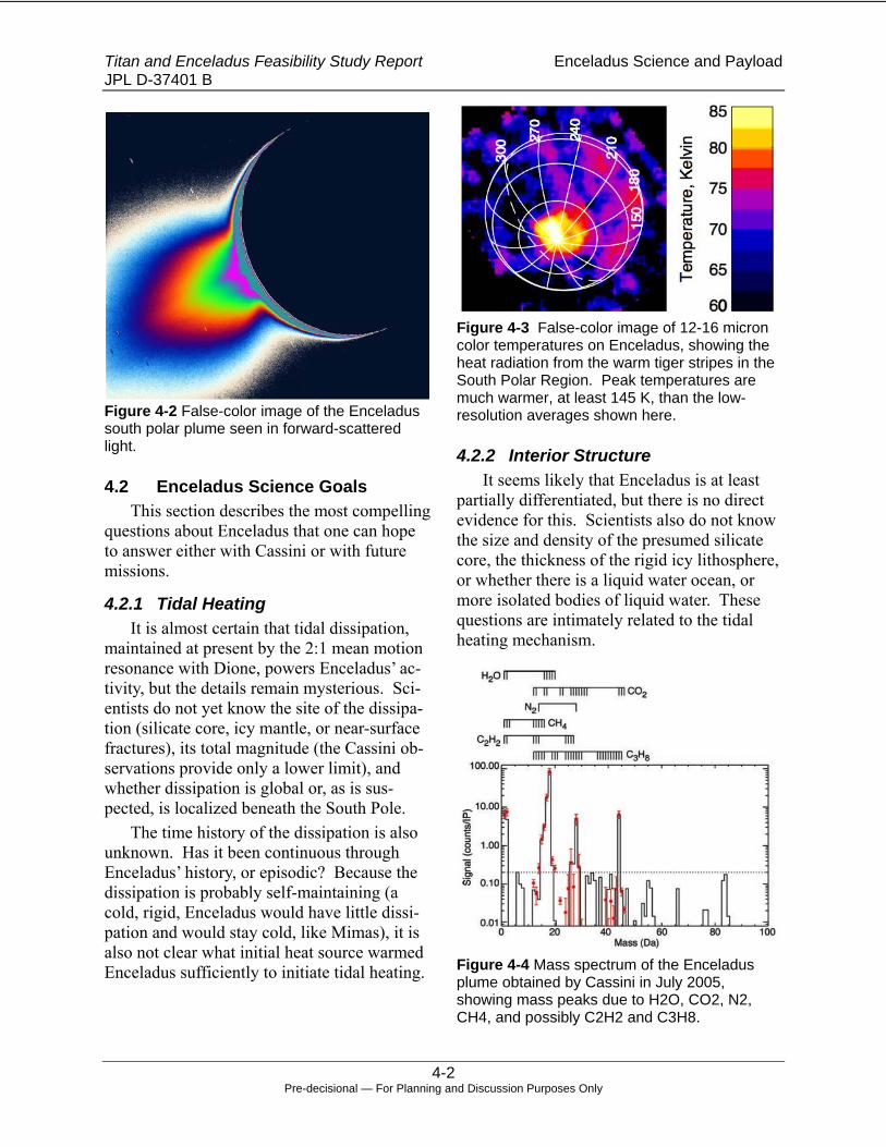
Titan and Enceladus Feasibility Study Report Enceladus Science and Payload JPL D-37401 B
4-2 Pre-decisional — For Planning and Discussion Purposes Only
Figure 4-2 False-color image of the Enceladus south polar plume seen in forward-scattered light.
4.2 Enceladus Science Goals This section describes the most compelling
questions about Enceladus that one can hope to answer either with Cassini or with future missions.
4.2.1 Tidal Heating It is almost certain that tidal dissipation,
maintained at present by the 2:1 mean motion resonance with Dione, powers Enceladus’ ac-tivity, but the details remain mysterious. Sci-entists do not yet know the site of the dissipa-tion (silicate core, icy mantle, or near-surface fractures), its total magnitude (the Cassini ob-servations provide only a lower limit), and whether dissipation is global or, as is sus-pected, is localized beneath the South Pole.
The time history of the dissipation is also unknown. Has it been continuous through Enceladus’ history, or episodic? Because the dissipation is probably self-maintaining (a cold, rigid, Enceladus would have little dissi-pation and would stay cold, like Mimas), it is also not clear what initial heat source warmed Enceladus sufficiently to initiate tidal heating.
Figure 4-3 False-color image of 12-16 micron color temperatures on Enceladus, showing the heat radiation from the warm tiger stripes in the South Polar Region. Peak temperatures are much warmer, at least 145 K, than the low-resolution averages shown here.
4.2.2 Interior Structure It seems likely that Enceladus is at least
partially differentiated, but there is no direct evidence for this. Scientists also do not know the size and density of the presumed silicate core, the thickness of the rigid icy lithosphere, or whether there is a liquid water ocean, or more isolated bodies of liquid water. These questions are intimately related to the tidal heating mechanism.
Figure 4-4 Mass spectrum of the Enceladus plume obtained by Cassini in July 2005, showing mass peaks due to H2O, CO2, N2, CH4, and possibly C2H2 and C3H8.

Titan and Enceladus Feasibility Study Report Enceladus Science and Payload JPL D-37401 B
4-3 Pre-decisional — For Planning and Discussion Purposes Only
4.2.3 Composition Enceladus’ high density of 1.61 g cm-3 in-
dicates a relatively high silicate/ice ratio, but the composition of the silicates or the details of the abundance and physical state of other volatiles in the ice fraction, or the degree of chemical processing that has occurred are un-known. It is possible that volatiles are stored in the form of clathrates, which would have implications for plume generation and internal temperatures (clathrates are highly insulating). Ammonia is an expected interior component and potentially potent anti-freeze, and its ab-sence from the plume is a puzzle. The abun-dance and complexity of organic molecules is of great interest.
Figure 4-5 Near-infrared composite image of Enceladus showing the concentration of the 3.44 µm C-H stretch band (red) along the south polar tiger stripes.
4.2.4 Tectonism The abundant tectonism evident on
Enceladus’ surface has many similarities to that seen on other icy satellites. It has not been determined whether the complex tectonic patterns we see are driven by convection in the ice mantle, possibly organized into plate
tectonics-like processes, tidal or spin-related stresses, or some combination. For many fea-tures it is not even clear whether they are con-trolled by compressive, extensional, or shear stresses. The dramatic spatial variations in tectonic intensity are also a puzzle.
Figure 4-6 An example of the wide variety of terrain types on Enceladus, including intense tectonic modification. The area shown is about 150 km across.
4.2.5 Cryovolcanism The origin of the spectacular plumes is one
of the major mysteries of Enceladus. Subli-mation of warm ice, boiling of liquid water, and decomposition of clathrates has all been proposed, and how the energy is continually supplied to the plume sources is not under-stood. The resurfacing rates due to plume par-ticles and gas, and their spatial distribution, are unknown. Escape rates are also not well known- it is possible that escape fluxes are large enough to have had a significant effect on Enceladus’ long-term chemical evolution. Scientists do not know the temporal variability of the plumes, whether low-level plume activ-ity occurs in regions other than the south polar terrain, or whether extrusive and intrusive cryovolcanism occurs in addition to the obvi-ous cryoclastic activity.

Titan and Enceladus Feasibility Study Report Enceladus Science and Payload JPL D-37401 B
4-4 Pre-decisional — For Planning and Discussion Purposes Only
Figure 4-7 Close-up of the south polar “tiger stripe” fissures that are the probable source of the plume, showing their blue color due to large ice grain sizes, and their enhanced thermal emission. The numbers are brightness temperatures in K, averaged over each 6x6 km mid-IR field of view.
4.2.6 Surface Processes Apart from the omnipresent water ice, lit-
tle is known about the surface composition of Enceladus, and less about the photolytic, ra-diolytic, or other chemical processes that oc-cur there. It has been proposed that surface chemistry could have a significant impact on the interior chemistry and perhaps even pro-vide a significant energy source.
4.2.7 Biological Potential Most intriguing of all is the biological po-
tential of Enceladus. This depends critically on the presence of liquid water, its long-term persistence, its organic and inorganic chemis-try, and the availability of chemical energy to power biochemistry, and is thus dependent on the answers to all the previous questions that have been asked. In the case of Enceladus, one may even hope to answer the question of whether life is present now.
4.3 Cassini Limitations Cassini is well equipped to address many
of these questions but is limited in several im-
portant respects. By the end of the extended mission (if approved) there will have been up to 12 flybys with ranges less than 3000 km, some perhaps as close as 25 km. However, the configuration of the spacecraft allows op-timization each flyby for only a few measure-ment goals (e.g., gravity, in-situ plume sam-pling, or remote sensing) so we may, for instance, have only two gravity passes in the tour, insufficient to map local gravity anoma-lies. The lack of dust shielding may limit the spacecraft’s ability to penetrate deeply into the plume while obtaining useful data, limiting our ability to investigate near-vent conditions that may reveal the plume source, and limiting sensitivity to potentially critical trace species in the plume.
Figure 4-8 The complex interaction between Enceladus and the E-ring, seen at high phase angles by Cassini.
Cassini’s instrumentation also has impor-tant limitations. The remote sensing instru-ments are not designed for rapid coverage of large areas during close flybys, allowing only “postage stamp” coverage at maximum resolu-tion: wide-field push broom sensors would make better use of precious time near closest approach. The mass resolution and range of the mass spectrometers in the INMS and CDA instruments is insufficient to uniquely identify organic molecules that might be critical in de-termining the biological potential of Encela-dus. Cassini also does not carry instrumenta-tion, such as a ground-penetrating radar, that

Titan and Enceladus Feasibility Study Report Enceladus Science and Payload JPL D-37401 B
4-5 Pre-decisional — For Planning and Discussion Purposes Only
can provide detailed information about the subsurface structure, and presence of liquid water, near the plume source, and has no abil-ity to directly measure tidal flexing, which would provide information on the possible presence of an ocean and the nature of the tidal heat source.
4.4 Rating and Down Selection of Mission Concepts
Despite these limitations, Cassini is a very capable mission for Enceladus science, and compelling follow-on missions must provide major advances over Cassini capabilities. The Enceladus SDT briefly considered multiple mission architectures as shown in the science traceability matrix (Table 4-1), and selected the two that seemed most likely to deliver worthwhile science within the cost cap for more detailed study.
The SDT evaluated the various mission concepts by assessing their ability to address the various science questions listed above. For each mission the team estimated whether it would provide a small, large, or very large increment in scientific understanding of each objective, beyond Cassini, as shown by color coding in Table 4-2. Then, each mission con-cept was assigned an overall numerical rating from 1 to 10, to reflect how well that mission would advance the overall knowledge of Enceladus. The overall rating differed slightly from the average rating in the various science categories, reflecting the fact that not all sci-ence goals are of comparable importance (for instance we considered an understanding of Enceladus’ biological potential to be more im-portant than understanding surface processes).
A single Enceladus flyby mission was considered and rejected: even with improved instrumentation compared to Cassini, the sci-ence return would be too small to be worth-while. However, the Study team did deter-mine costs for this very simple mission concept so its potential scientific value is briefly described in the next section. The
team also considered passive or instrumented impactors as mission components and rejected these on scientific grounds: a passive impactor to produce a plume for analysis was thought to be of limited use given the presence of the natural plumes, and an instrumented impactor would provide only a few seconds of data at ranges closer than could be achieved with a flyby mission.
Mission components that were considered to be scientifically valuable, but almost cer-tainly too expensive for this study, included hard landers (designed to survive impact), soft landers, and Enceladus orbiters. The team also briefly considered combined Ti-tan/Enceladus missions, but it seemed likely that attempting to address the very different science goals for each target, while perhaps more cost-effective than sending a separate mission to both targets, would be unlikely to fit within the study cost cap. In addition, or-bital tours designed to maximize both Titan and Enceladus flybys would produce fewer Enceladus flybys than Enceladus-only mis-sions, reducing their scientific value for Enceladus.
The remaining missions that were chosen for more detailed study were an Enceladus sample return on a free-return trajectory to Earth, and a Saturn orbiter with multiple Enceladus flybys, and the single Enceladus flyby. For each of these missions a straw man payload was selected that the SDT believed was representative of the minimum necessary for a worthwhile mission.

Titan and Enceladus Feasibility Study Report Enceladus Science and Payload JPL D-37401 B
4-6 Pre-decisional — For Planning and Discussion Purposes Only
Table 4-1 Science Trace Matrix.
Objective
Overall Score ImagerThermal Mapper
Magneto-meter
Doppler Gravity
Sounding Radar
Dust Analyzer Gas Analyzer Overall Score Imager
Thermal Mapper
Dust Analyzer Gas Analyzer
Sample Return Overall Score Imager
Thermal Mapper
Dust Analyzer
Gas Analyzer
Tidal Heating
Dissipation mechansim, spatial distribution, time variability XXX XX XXX X X XX X X XX X X XX
Interior Structure
Size of core, thickness of lithosphere, presence of ocean XXX XX X XXX XX XX X X X X X X X X X X X
Buik Composition Compositon of interior XX X X XX XXX X XX XXX X X XX
TectonicsLithospheric stresses, tectonic mechanisms XX XX XX X X X X X X X X X
Cryovolcanism
Nature of plume source, resurfacing and escape rates, spatial distribution, other forms of cryovolcanism XXX XXX XXX X XXX XX XX XX XX XX X XX XXX XX XX XX X XX
Surface Processes
Photolytic or radiolytic chemistry, interaction with E-ring X X X X X X X X x X X X
Biological Potential
Presence and longevity of liquid water, chemistry, energy sources, presence of life XX X XX XX X XX XX XX XXX X XX XX XXX XX X XX XX
Single FlybySaturn Orbiter / Multiple Flybys Sample Return

Titan and Enceladus Feasibility Study Report Enceladus Science and Payload JPL D-37401 B
4-7 Pre-decisional — For Planning and Discussion Purposes Only
Table 4-2 Relative science value of Enceladus missions.
4.5 Enceladus Plume Sample Return Enceladus provides the unique opportunity
to obtain samples from the interior simply by flying past the moon and collecting plume par-ticles or gas. It thus may provide the only op-portunity, for the foreseeable future, to study the interior of an icy satellite using the full future capabilities of terrestrial laboratories. Plume samples may reveal much about condi-tions in the plume source region and the deeper interior (for instance, the presence of nitrogen rather than ammonia has recently been used to argue for high temperatures in Enceladus’ interior), and would probably, for instance, allow determination of whether liq-uid water was present at the plume source. Characteristics such as stable element isotope ratios would provide valuable insights into the
formation of Enceladus and the Saturn system as a whole.
Most intriguing, however, is the opportu-nity to investigate the biological potential of Enceladus at a level of detail impossible with in situ or remote sensing observations. Labo-ratory analysis of returned organic compounds would be able to determine organic signatures such as chirality that are difficult to measure in situ (at least, without entering Enceladus orbit to allow collection of gas samples at low speed). There is also the real possibility of returning biological structures entrained in the plume, should any exist: on Earth, thermo-philic bacteria are found in Yellowstone gey-ser spray and plankton is found in terrestrial cirrus clouds after hurricanes.

Titan and Enceladus Feasibility Study Report Enceladus Science and Payload JPL D-37401 B
4-8 Pre-decisional — For Planning and Discussion Purposes Only
Figure 4-9 Tracks of comet grains captured in aerogel by the Stardust mission.
The potential of a sample return mission depends greatly on the degree of sample pres-ervation that is possible both during capture and delivery back to Earth. Stardust success-fully obtained samples from comet Wild-2 at 6.1 km/sec using aerogel, but Enceladus en-counter speeds on a free-return trajectory may be as high as 14 km/sec, well beyond current aerogel capabilities, and round trip times may be greater than 18 years. It is not necessary to return ice grains themselves to Earth, but it would be important to bring back, and to be able to identify and analyze, intact organic molecules (or even any biological structures) that might be present within the ice grains at the time of capture. Tracks in the Stardust aerogel indicate that ice grains were captured intact by the aerogel and later sublimed, leav-ing behind their less volatile contents. Indeed, the Stardust aerogel contains species that would not have survived aerocapture unless protected within ice grains, providing some hope that icy Enceladus plume particles might similarly protect during capture any delicate molecules or other structures that they con-tained, and allow them to be returned to Earth.
This mission depends on the Enceladus plume being active during the single flyby of the moon. The fact that the plume seen by Cassini is derived from over 1 dozen sources spread over the ~130 km extent of the tiger stripes makes it unlikely that all or most sources would shut off in the next 20 years, unless there is some central control mecha-
nism that operates on timescales less than a few decades, which seems unlikely. The E-ring, thought to consist of Enceladus plume particles, is known to be stable on several dec-ade timescales and is thus likely to provide at least some samples even in the event of plume inactivity.
Return of gas samples, if feasible, would enhance science return, as some chemical spe-cies may be enhanced in the gas relative to the plume particles.
The Enceladus sample return mission con-cept includes some remote sensing (visible camera and thermal mapper) and in situ sci-ence (gas and dust analyzers) to improve un-derstanding of the plume source, because the science risk for this mission was considered to be unacceptably high without some science return before delivery of samples back to Earth. These instruments are identical to those carried on the Saturn Orbiter / Multiple Enceladus Flyby mission concept (Section 4.6), and will be discussed in more detail there.
4.6 Saturn Orbiter with Multiple Enceladus Flybys
This mission concept is somewhat Cassini-like, with multiple Enceladus flybys from Sat-urn orbit, but carries greatly improved instru-mentation compared to Cassini in order to make compelling advances in answering sci-ence questions. The concept also includes nearly 40 flybys, about three times as many as are currently planned by Cassini. It is likely that the spacecraft would require armoring with Stardust-like shields to allow flybys close to the plume source that might be considered too dangerous for Cassini. The minimum in-strument complement includes the following:
• Push broom CCD imager with 3-4 col-ors in the visible and nearest IR, per-haps similar to MVIC on New Hori-zons. Such an instrument could cover a 200 x 35 km swath at 7 m/pixel from 300 km range on each flyby, greatly

Titan and Enceladus Feasibility Study Report Enceladus Science and Payload JPL D-37401 B
4-9 Pre-decisional — For Planning and Discussion Purposes Only
improving on Cassini’s resolution and coverage over the course of the mis-sion (Cassini has so far taken only a single image at comparable resolution, covering 2 x 2 km). This instrument would address many of our science goals, in particular the understanding of the plume source, cryovolcanism in general, and tectonics.
• Push broom thermal mapper covering the 8 – 20 micron wavelength range at two wavelengths, perhaps similar to THEMIS on Mars Odyssey. This in-strument could cover a 200 x 30 km swath at 100 m/pixel per flyby, com-pared to Cassini’s best resolution in the thermal IR, with extremely limited coverage, of about 1 km. Mapping thermal emission from the tiger stripes at this resolution will constrain the na-ture of the plume source, tidal heating mechanisms, and perhaps tectonic and other surface processes.
Figure 4-10 Comparison of resolution vs. Enceladus coverage expected for Cassini in the visible and thermal infrared through the end of the extended mission (dashed lines), to that possible with our proposed Saturn orbiter with multiple Enceladus flybys (solid lines). Major improvements in high-resolution coverage are possible.
• Sounding radar, comparable to that proposed for the original Europa or-biter in 1999. This would allow sub-surface sounding of the plume source
region and other areas on Enceladus, providing important information on the subsurface nature of the source region, the possible presence of liquid water, and the structure of the lithosphere that is inaccessible to Cassini.
• Mass spectrometer with much im-proved mass resolution and coverage compared to Cassini, covering masses up to 200 at resolution better than 1 AMU. This instrument would be suf-ficient to identify quite complex or-ganic molecules in the plume gases. Increased sensitivity compared to Cas-sini would be possible thanks to multi-ple passes through the plume at closer range than may be safe with Cassini. Such a mass spectrometer has the po-tential to test for the presence of life on Enceladus: for instance enhanced con-centrations of a small subset of organic molecules, compared to others that would be equally likely to be produced by abiotic processes, would be strong evidence for the presence of life.
• Dust analyzer capable of determining particle masses, velocities and compo-sitions. The Cassini CDA instrument includes a mass spectrometer that can determine particle compositions, but tenfold improvement in mass resolu-tion are now possible and would allow identification of organic molecules, or their fragments, from the vapor plume produced by a particle impact. The de-tailed composition of the ice particles is likely to reveal much about their source, including whether liquid water was involved in their production.
• Magnetometer similar or identical to that carried by Cassini, for magnetic sounding of Enceladus’ interior. The advantage over Cassini here comes from the large number of flybys, many of which will have identical geometry except for ~1.5% amplitude changes in

Titan and Enceladus Feasibility Study Report Enceladus Science and Payload JPL D-37401 B
4-10 Pre-decisional — For Planning and Discussion Purposes Only
the ambient Saturnian magnetic field due to the small rotational modulation of the field, and the additional similar-sized modulation due to changes in Enceladus’ distance from Saturn as the orbit precesses (precessional period is 1.31 years compared to the 0.55 year duration of each planned campaign of similar-geometry flybys). This may allow detection of a subsurface ocean, as has been done for the icy Galilean satellites by Galileo.
• Doppler tracking for gravity measure-ments, using the main communications antenna. The large number of possible gravity passes will allow mapping of Enceladus’s gravity field in consider-able detail, providing information on the degree of differentiation and the structure of the lithosphere. For in-stance, the presence of a gravity anom-aly at the South Pole would provide a test of the hypothesis that a low-density diapir or other mass anomaly caused reorientation of Enceladus to align the mass anomaly with the south rotation pole. Tidal flexing due to the precession of the orbit may also be measurable, constraining global inte-rior structure.
Additional instruments would of course be desirable if resources permitted, particularly a near-IR spectrometer to map surface composi-tion.
4.7 Single Enceladus Flyby: The Simplest Possible Mission
This mission concept would involve flying a low cost lightweight New Horizons-like spacecraft, with instrumentation optimized for Enceladus, on a trajectory that would provide a single close Enceladus flyby without enter-ing Saturn orbit. The straw man payload is very similar to the Saturn orbiter described above, but without the magnetometer or Dop-pler tracking that, in a single flyby, would
provide no advantage over Cassini, and with-out the radar sounder. A single pass through the plume near closest approach with an ad-vanced mass spectrometer and dust instrument could provide valuable information on the or-ganic chemistry of the plume source beyond what is possible with Cassini, but the informa-tion would be limited compared to the multi-ple passes possible with a Saturn orbiter. The single imaging and thermal mapping swath would also provide valuable information on the nature of the plume source region, with spatial resolution and coverage that would be a significant improvement over Cassini. The radar sounder is not included because though it might produce unique science on its single pass over the plume source region, science return would be very limited because only a very small region could be probed on a single flyby, and there would be no chance to fine-tune the investigation to optimize it for the completely unknown subsurface properties of Enceladus. Overall, the total science return, while not negligible, would be much less than either of the above missions, and was not con-sidered to be scientifically compelling.

Titan and Enceladus Feasibility Study Report Mission Architecture Concepts JPL D-37401 B
5-1 Pre-decisional — For Planning and Discussion Purposes Only
5. Mission Architecture Concepts
5.1 Overview
5.1.1 The Saturn System Both Titan and Enceladus are parts of the
Saturn system, so a brief overview of that sys-tem and its place in the solar system is useful. Saturn orbits the sun at an average distance of ~9.5 AU. Its orbit is somewhat more eccentric than Earth’s so its heliocentric distance varies seasonally (over the course of a Saturn year, which is 29.46 terrestrial years) from 9.05 to 10.03 AU. Insolation over those distance ex-tremes varies from 1/82 down to 1/101 of that at 1 AU, making solar electric power challeng-ing at best.
Within the Saturn system Saturn’s obliq-uity, the inclination of its equatorial plane to the plane of its heliocentric orbit is 26.73°, as shown in Figure 5-1. This results in large sea-sonal variations of a spacecraft’s arrival ge-ometry with respect to Saturn’s equatorial plane, along with the variations in heliocentric distance. Over one Saturn “season” (1/4 of a Saturn year) an approaching spacecraft can see Saturn’s equatorial plane anywhere from edge-on to open by ~30° or more.
Figure 5-1 Saturn obliquity.
Also within the Saturn system is a large retinue of satellites, some associated with the spectacular and diverse ring system. All the rings and associated “ringmoons” have orbits that are aligned almost exactly with Saturn’s equatorial plane. All the regular satellites from Titan inward are also closely aligned with the
equatorial plane, though not as tightly as the rings, and have small but non-zero eccentrici-ties. Table 5-1 gives mass, size, and orbit pa-rameters for the four satellites pertinent to po-tential Titan and Enceladus missions: Titan and Enceladus themselves, and Dione and Rhea.
Table 5-1 Satellite characteristics.
Figure 5-2 is a polar-view illustration of
the system’s gross geometry, highlighting the locations of the four satellites’ orbits. In that figure the main ring system, rings A, B, C, D, and F, are seen in the tan color relatively near Saturn. The E ring is roughly centered around Enceladus orbit. Cassini data suggest that Enceladus plumes are the source of material for the E ring.
Figure 5-2 Satellite orbits in the Saturn system.

Titan and Enceladus Feasibility Study Report Mission Architecture Concepts JPL D-37401 B
5-2 Pre-decisional — For Planning and Discussion Purposes Only
5.1.2 Architectures Studied Clearly, detailed studies of a comprehen-
sive set of science objectives for Titan and Enceladus, convolved with all possible mis-sion architectures for addressing those objec-tives, greatly exceeds the scope of this study. The approach taken to reduce the task to a tractable level was to examine at a high level the range of appropriate architectures, reject-ing those that were almost certain to exceed by far the $1B cost limit or to provide insuffi-cient science return. This process yielded five mission concepts deemed most likely to pro-vide worthwhile science while meeting the $1B cap. To those five were added two mis-sions whose science was deemed insufficient but whose simplicity almost guaranteed meet-ing the cost cap. Table 5-2 below lists these seven mission concepts. They are discussed in much greater detail in Section 5.5 below. Table 5-2 Summary of mission concepts studied.
Mission Concept Name Mission Type Science
Acceptability Titan Orbiter Target body
orbiter Acceptable
Titan Aerobot In situ balloon Acceptable Titan Lander In situ lander Acceptable Titan Entry Probe
Atmospheric entry probe
Unacceptable
Enceladus Multiple Flyby
Saturn orbiter with Enceladus flybys
Acceptable
Enceladus Plume Sample Return
Sample return from single flyby
Acceptable
Enceladus Single Flyby
Simple flyby Unacceptable
5.2 Travel to Saturn Saturn’s distant location in the sun’s grav-
ity well makes for high-energy and long-duration transfers from Earth. The two Voy-ager spacecraft demonstrated four-year trans-fers to Saturn using a Jupiter gravity assist (JGA), but only one of the mission concepts studied here, the Enceladus Single Flyby, could make use of a JGA. That concept’s
flight system is sufficiently low in mass that it could use a direct Earth-to-Jupiter trajectory, arriving at Jupiter while it is still in position for a gravity assist to Saturn. The other con-cepts require inner solar system gravity assists to reach Jupiter, which will have moved out of GA position by the time they arrived.
A survey of Earth-to-Saturn transfer trajec-tories from previous studies and from this study shows a wide range of trip times and payload capacities for a given launch vehicle. Figure 5-3 plots delivered mass vs. trip time for a variety of chemical propulsion and SEP trajectories, all using at least one inner solar system gravity assist. All but three use the per-formance figures of an Atlas V 531 launch ve-hicle for ease of comparisons among different trajectories, and the remaining three use an Atlas V 551 to show the mass capacity in-crease available from launch vehicle upgrades. The naming convention for these trajectories lists the first letter of planets encountered (in-cluding launch from Earth) in the order of en-counter, so “EEJS” is a trajectory that launches from Earth, then performs an Earth gravity assist (EGA) flyby, then a JGA flyby, and finally arrives at Saturn. Number designa-tions after the planet-encounter sequence refer to trajectories between successive Earth en-counters. Designations of “2+” or “2-“, for example, mean Earth-to-Earth transfers of slightly more than or slightly less than 2 years, respectively. The “2-3” designation indicates a 2-3 Earth-resonant, such that the spacecraft orbits the sun twice while Earth orbits three times; it can be quasi-resonant, i.e. not exactly 3 years to complete the transfer. SEP trajecto-ries use Solar Electric Propulsion (SEP), while “Chem” trajectories use only conventional chemical rocket propulsion for maneuvers. Some chemical trajectories that encounter the same planet without a different planet in be-tween require a relatively large (many hun-dreds of m/s to over a km/s) propulsive deep-space maneuver (DSM), with the concomitant decrease in delivered mass due to the mass of

Titan and Enceladus Feasibility Study Report Mission Architecture Concepts JPL D-37401 B
5-3 Pre-decisional — For Planning and Discussion Purposes Only
the large propulsion system for the DSMs. The EEES trajectories are good examples of this, each requiring two DSMs. Note that trajecto-
ries using a direct Earth-to-Jupiter leg are not included in this chart.
Figures 5-4 and 5-5 show example chemi-cal and SEP transfer trajectories, respectively.
Net Mass to Saturn on Atlas V 531 vs. Flight TimePropulsion system mass is subtracted, where applicable
1500
2000
2500
3000
3500
4000
4500
5000
5.0 6.0 7.0 8.0 9.0 10.0 11.0 12.0
Flight Time (yr)
Net
Mas
s (k
g)
EEJS 2+, SEP
EEJS 2-3, SEP
EEJS 2+, Chem
EEJS 2+, ChemAtlas 551EES 2+, SEP
EES 2-3, SEP
EES 3+, SEP
EEES, Chem
EEES, ChemAtlas 551EVEEES, Chem
EVEEES, ChemAtlas 551
Figure 5-3 Mass delivered to Saturn approach and transfer time, parametric in trajectory type.
Figure 5-4 Example chemical trajectory to Saturn.
Figure 5-5 Example SEP trajectory to Saturn.

Titan and Enceladus Feasibility Study Report Mission Architecture Concepts JPL D-37401 B
5-4 Pre-decisional — For Planning and Discussion Purposes Only
The chemical trajectory is the purely bal-listic EVEEES from Figure 5-4, and the SEP one is an EES XIPS trajectory. Dotted curves in those figures represent, in order of increas-ing radius, the orbits of Venus, Earth, Mars, Jupiter, and Saturn. Red arrows in the SEP example show SEP thrusting directions.
5.3 Mission Option Trades Most of these mission concept studies
made specific choices regarding transfer and, where appropriate, orbit insertion. First, the use of SEP was assumed as a means to shorten trip time to Saturn while increasing delivered mass for a given launch vehicle, and to pro-vide greater programmatic flexibility in the form of greater launch date flexibility. Orbit insertions, whether into Titan or Saturn orbit, use aerocapture in Titan’s atmosphere, again to greatly increase mass delivered into orbit from a given launch vehicle.
Given the focus of this study on minimiz-ing mission costs, these assumptions were tested by developing mission and flight vehi-cle designs that evaluated alternative ap-proaches, using the Titan Orbiter mission as an example. For transfer trajectories the alter-native to SEP would be a chemical transfer, in which the launch vehicle must impart to the flight system the energy needed to reach the
location for the first DSM or non-Earth grav-ity assist, and thereafter gravity assists (and possibly additional DSMs) lead to the final ballistic transfer to the Saturn system. For shorter trip times studied (9 to 10 years) the transfer requires at least one DSM of roughly 1.5 km/s, and the flight system must provide this significant delta-V. Purely ballistic trajec-tories with good delivered mass characteristics were also identified, but involve trip times on the order of 10.5 to 11 years.
For orbit insertion propulsive capture is an alternative to aerocapture. Propulsive capture could potentially simplify spacecraft design by eliminating the packaging restrictions of the aeroshell and the complexity of aerocapture-associated hardware. However, the required delta-V for Titan capture is ~4 km/s or more, which would add a very large propulsion sub-system and significant propellant mass to the flight system.
Flight system designs were developed and costed for the four mission options as shown in Table 5-3. Flight system masses shown rep-resent total mass at Titan approach, which was used to determine flight time and required launch vehicle. Flight system costs include the costs of all flight elements needed to carry out the mission.
Table 5-3 Mission Option Trade. Titan Orbit Insertion
Aerocapture Propulsive Capture
SEP
Mass at Titan Approach: 1970 kg Elements: SEP Stage, Orbiter, Aeroshell Flight System Cost: $488M Flight Time: 6 yr Launch Vehicle: Atlas 521
Mass at Titan Approach: 7350 kg Not practical within Launch Vehicle constraints
Tran
sfer
Met
hod
Chem
ical Mass at Titan Approach: 2185 kg
Elements: Orbiter, Aeroshell Flight System Cost: $396M Flight Time: >9 yr Launch Vehicle: Atlas 531
Mass at Titan Approach: 7350 kg Not practical within Launch Vehicle constraints

Titan and Enceladus Feasibility Study Report Mission Architecture Concepts JPL D-37401 B
5-5 Pre-decisional — For Planning and Discussion Purposes Only
The simplest conclusion drawn from this trade is that propulsive capture at Titan is not an option for this study, given the desire to avoid the most costly launch vehicles. The mass penalty incurred for the inclusion of the large propulsion system required places the flight system mass well beyond the range of the largest launch vehicles appropriate to this study.
The trade between SEP and chemical transfer options is certainly more open. The difference in flight system cost between the two transfer options is ~$92M. However, this difference is somewhat offset by the chemical option’s 50% greater flight time to Titan, which incurs additional mission operations costs and mission risk. Additionally, the chemical option’s upgraded propulsion capa-bility for performing DSMs requires some-what greater flight system mass and could drive the need for a more capable launch vehi-cle, incurring additional mission cost.
The team decided that for this study the benefits derived from a SEP-based mission architecture were sufficiently valuable that all scientifically justifiable mission concepts use the SEP option. Should any of these missions go forward, further trades are appropriate to refine and confirm this conclusion.
5.4 Aerocapture Aerocapture is a means of capturing into a
useful orbit at a target body, from a hyperbolic (non-captured) approach, using aerodynamic drag instead of rocket propulsion to reduce the spacecraft’s energy for capture. Although the concept is fundamentally simple, implement-ing a practical aerocapture using a real atmos-phere, with all its uncertainty and variability, is a complex and demanding task. Notably it has never had a flight demonstration, though such a demonstration might happen in the near future, as discussed below. Figure 5-6 illus-trates at the simplest level the steps of the aerocapture process.
Figure 5-6 Fundamental architecture of the aerocapture process.

Titan and Enceladus Feasibility Study Report Mission Architecture Concepts JPL D-37401 B
5-6 Pre-decisional — For Planning and Discussion Purposes Only
The process begins with Step 1 in the lower left of the figure with a spacecraft’s hy-perbolic approach to the target planet (or any body with a sufficiently dense atmosphere), navigated such that the spacecraft enters the planet’s atmosphere. The navigation must be sufficiently accurate to prevent two problem-atic outcomes: 1) excessively deep penetra-tion of the atmosphere, where the spacecraft encounters atmosphere so dense that is causes burn-up or complete, irretrievable entry into the atmosphere; and 2) excessively shallow penetration of the atmosphere, where it is not sufficiently dense to effect the speed reduction needed for capture.
Even given perfect navigation to the entry point, Step 2 of the process, the actual atmos-pheric flight of the spacecraft or “aerocapture maneuver”, requires real-time navigation and flight path control. Real atmospheres never agree exactly with even the best of models, and are also subject to unpredictable varia-tions with time. The flight system must meas-ure the actual atmosphere encountered and reconstruct the flight path actually taken, ad-just its flight path to encounter atmosphere within tolerances of the desired densities, and guide it to an exit from the atmosphere near the preplanned location and at the proper ve-locity. The same monitor-and-adjust approach handles entry navigation and delivery errors. This is not possible without on-board, real-time flight path measurement, orbit propaga-tion and comparison to the desired result, and corrections that involve the aerodynamic equivalent of maneuver design and execution. Multiple methods for flight path control are in the aerocapture literature, but the method cur-rently at the highest Technology Readiness Level (TRL) is the “rigid lifting body” method. This places the spacecraft within a rigid-body aeroshell with a significant lift co-efficient, and control of the aeroshell’s roll angle (and possibly attack angle) steers the system along the proper path.
One by-product of this high-speed (hyper-sonic) atmospheric flight is aerodynamic heat-ing. The aeroshell must have a surface Ther-mal Protection System (TPS) to prevent damage to spacecraft components either by heat or aerodynamic forces. Over the course of an aerocapture maneuver, practical TPS materials become heat-soaked. If the heat ab-sorbed is sufficiently large and the aeroshell is retained after atmospheric exit, heat propagat-ing inward (“soak back”) could heat the space-craft to the point of failure. For this reason, some aerocapture maneuvers must be fol-lowed immediately by jettisoning the aeroshell to prevent this heat soak back.
Upon exit from the atmosphere the space-craft is in an eccentric orbit whose periapse is within the atmosphere and whose apoapse is outside it, illustrated by Step 3 in Figure 5-6. This is a very temporary situation because re-entry into dense regions of the atmosphere is undesirable. Upon reaching the first apoapse of this orbit a “periapse raise maneuver” (PRM), Step 4 in the figure, lifts periapse out of the atmosphere and establishes the final stable orbit, which can be eccentric or circular. Additional minor maneuvers might be needed to correct aerocapture maneuver errors such as apoapse altitude errors, or to modify the orbit for other purposes.
Although aerocapture might seem an un-duly risky means for achieving delta-V, the mass savings it offers enables some missions. Orbit insertions using propulsive capture have been demonstrated many times in the past. However, the delta-V requirements for orbit insertion at some solar system destinations overtax current chemical rocket propulsion technology. As the delta-V needed from a chemical propulsion system grows, the propel-lant mass needed for that delta-V grows quasi-exponentially. However, detailed analyses by NASA’s Aerocapture Systems Analysis Team (ASAT) indicate that the mass of an aerocap-ture system grows only quasi-linearly with delta-V required, so beyond some threshold
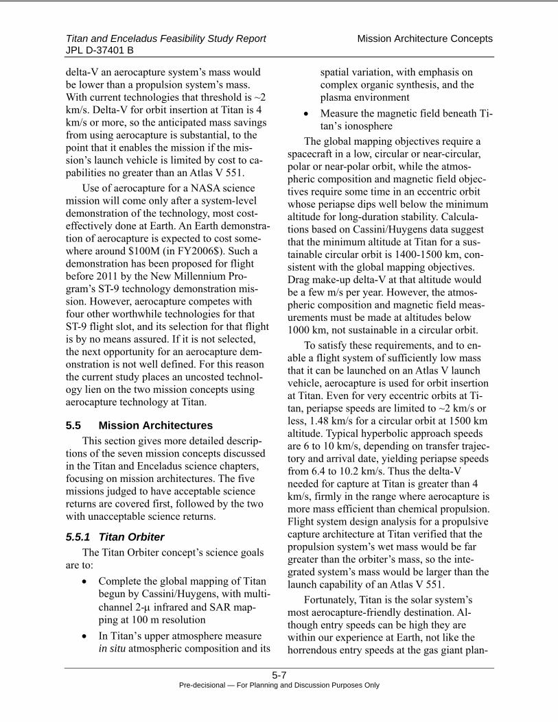
Titan and Enceladus Feasibility Study Report Mission Architecture Concepts JPL D-37401 B
5-7 Pre-decisional — For Planning and Discussion Purposes Only
delta-V an aerocapture system’s mass would be lower than a propulsion system’s mass. With current technologies that threshold is ~2 km/s. Delta-V for orbit insertion at Titan is 4 km/s or more, so the anticipated mass savings from using aerocapture is substantial, to the point that it enables the mission if the mis-sion’s launch vehicle is limited by cost to ca-pabilities no greater than an Atlas V 551.
Use of aerocapture for a NASA science mission will come only after a system-level demonstration of the technology, most cost-effectively done at Earth. An Earth demonstra-tion of aerocapture is expected to cost some-where around $100M (in FY2006$). Such a demonstration has been proposed for flight before 2011 by the New Millennium Pro-gram’s ST-9 technology demonstration mis-sion. However, aerocapture competes with four other worthwhile technologies for that ST-9 flight slot, and its selection for that flight is by no means assured. If it is not selected, the next opportunity for an aerocapture dem-onstration is not well defined. For this reason the current study places an uncosted technol-ogy lien on the two mission concepts using aerocapture technology at Titan.
5.5 Mission Architectures This section gives more detailed descrip-
tions of the seven mission concepts discussed in the Titan and Enceladus science chapters, focusing on mission architectures. The five missions judged to have acceptable science returns are covered first, followed by the two with unacceptable science returns.
5.5.1 Titan Orbiter The Titan Orbiter concept’s science goals
are to: • Complete the global mapping of Titan
begun by Cassini/Huygens, with multi-channel 2-μ infrared and SAR map-ping at 100 m resolution
• In Titan’s upper atmosphere measure in situ atmospheric composition and its
spatial variation, with emphasis on complex organic synthesis, and the plasma environment
• Measure the magnetic field beneath Ti-tan’s ionosphere
The global mapping objectives require a spacecraft in a low, circular or near-circular, polar or near-polar orbit, while the atmos-pheric composition and magnetic field objec-tives require some time in an eccentric orbit whose periapse dips well below the minimum altitude for long-duration stability. Calcula-tions based on Cassini/Huygens data suggest that the minimum altitude at Titan for a sus-tainable circular orbit is 1400-1500 km, con-sistent with the global mapping objectives. Drag make-up delta-V at that altitude would be a few m/s per year. However, the atmos-pheric composition and magnetic field meas-urements must be made at altitudes below 1000 km, not sustainable in a circular orbit.
To satisfy these requirements, and to en-able a flight system of sufficiently low mass that it can be launched on an Atlas V launch vehicle, aerocapture is used for orbit insertion at Titan. Even for very eccentric orbits at Ti-tan, periapse speeds are limited to ~2 km/s or less, 1.48 km/s for a circular orbit at 1500 km altitude. Typical hyperbolic approach speeds are 6 to 10 km/s, depending on transfer trajec-tory and arrival date, yielding periapse speeds from 6.4 to 10.2 km/s. Thus the delta-V needed for capture at Titan is greater than 4 km/s, firmly in the range where aerocapture is more mass efficient than chemical propulsion. Flight system design analysis for a propulsive capture architecture at Titan verified that the propulsion system’s wet mass would be far greater than the orbiter’s mass, so the inte-grated system’s mass would be larger than the launch capability of an Atlas V 551.
Fortunately, Titan is the solar system’s most aerocapture-friendly destination. Al-though entry speeds can be high they are within our experience at Earth, not like the horrendous entry speeds at the gas giant plan-

Titan and Enceladus Feasibility Study Report Mission Architecture Concepts JPL D-37401 B
5-8 Pre-decisional — For Planning and Discussion Purposes Only
ets themselves. Also like Earth the atmosphere is mostly nitrogen, without troublesome abun-dances of other more problematic species. The primary non-nitrogen component of Titan’s atmosphere is methane (CH4); Cas-sini/Huygens measured the methane abun-dance there at less than 2%, so radiative heat-ing is not a serious issue for aeroshells at Titan. Titan’s relatively low mass and thus low gravitational acceleration results in large at-mospheric scale heights at all altitudes, de-creasing the consequences of altitude errors. The net effect for flight systems is that aero-capture at Titan can be achieved with a cur-rent-technology, low lift-to-drag ratio (L/D) aeroshell. ASAT studies indicate an L/D of 0.2 is sufficient, with margin, for successful aero-capture at Titan. Many previous aeroshell ge-ometries, including the Apollo Command Module and the MER entry aeroshells, dem-onstrated L/D at this level or greater. As soon as an Earth demonstration of aerocapture is achieved, the technology will be ready for Ti-tan.
Aerocapture at Titan follows the classical example closely. Navigation to entry is tight but within demonstrated capabilities. The or-biter spacecraft handles all computations, and commands the attitude control RCS systems in the aeroshell. The vehicle descends to 2-300 km altitude during the 10 to 15 minute ma-neuver and jettisons the aeroshell upon exit. A 120 m/s maneuver roughly 2.5 hours later raises periapse to 1500 km altitude, where a
much smaller maneuver completes the circu-larization. The Titan b-plane approach aspect (“clock angle”) is chosen to yield a polar orbit for global mapping.
Classical aerocapture at Titan would de-prive the atmospheric composition and mag-netic measurements of their multiple deeper dips into the atmosphere, so a modification of the classical approach restores that capability. Instead of aerocapturing directly into the cir-cular mapping orbit, the spacecraft aerocap-tures into an initially eccentric orbit with apoapse altitude of ~4000 km. The PRM raises the periapse to an altitude less than 1500 km, but high enough to be consistent with spacecraft safety for an initial checkout period. After that checkout period periapse is decreased to less than 1000 km altitude, per-haps 800 or 900 km, to begin an aerobraking phase that also affords the compositional and magnetic measurements, as illustrated in Fig-ure 5-7a. Aerobraking has been demonstrated successfully at Venus and is used regularly at Mars. At both those targets the atmospheric flight speeds are much greater than at Titan, so aerodynamic heating is much less an issue: single-pass delta-V of one or two m/s is no problem at all for the spacecraft. About 20 days of such aerobraking drops apoapse to ~1500 km, so a PRM then circularizes the or-bit for mapping, illustrated in Figure 5-7b. The composition and magnetometry objectives are satisfied in that 20-day period.
Figure 5-7 Science orbits for the Titan Orbiter mission concept.

Titan and Enceladus Feasibility Study Report Mission Architecture Concepts JPL D-37401 B
5-9 Pre-decisional — For Planning and Discussion Purposes Only
Figure 5-8 Example mission timeline for the Titan Orbiter mission concept. 2018 launch assumed.
After the aerobraking/in situ science phase is complete the mission settles into routine orbital mapping science operations for the re-mainder of the 2-year science mission. IR and SAR data are acquired and stored during ~2-hr mapping passes. Those data are downlinked to Earth via a Ka-band radio link at ~50 kbps (to a 34-m ground station). Most likely the downlink cannot be performed as a single transmission stream because Titan will occult the spacecraft for part of the orbit. However, the time equivalent of two 8-hour DSN passes is sufficient to downlink all data from one mapping pass. The project science team evaluates data as they are available and pro-vides observational “tweaks”, but does not engage in wholesale replanning of the opera-tional strategy. This operational concept achieves global mapping, with all data on the ground, by the end of the 2-year prime mis-sion. Figure 5-8 gives an example timeline for the mission, assuming launch in 2018.
5.5.2 Titan Aerobot The Titan Aerobot concept’s science goals
are to: • Spend a minimum of one terrestrial
year drifting in Titan’s tropospheric winds, accessing diverse locales.
• At areas of interest image at 1 m reso-lution and acquire subsurface radar data.
• Make atmospheric in situ composi-tional measurements without ground contact.
• Make frequent meteorological meas-urements.
Of course these objectives require placing a long-duration balloon, possibly a Montgolfi-ere design, into Titan’s atmosphere. The Huy-gens entry and initial descent under a para-chute is very similar to those events in the aerobot mission. The balloon would deploy at an altitude somewhat above its cruise altitude of ~10 km, while in a stable descent under the parachute. Unlike Huygens this mission would not insert into Saturn or Titan orbit before en-try, but instead would enter directly, without first decelerating from the hyperbolic inter-planetary trajectory. Thus no science data would be acquired until delivery into Titan’s atmosphere. Fortunately, as discussed above, such entry at Titan is relatively benign and does not unduly challenge entry system and TPS technologies.
For cost reasons this mission concept’s ar-chitecture does not include an accompanying orbiter, so the aerobot must communicate di-rectly-to-Earth (DTE). Earlier studies show that for a given mission duration, this DTE architecture reduces the total data volume be-tween one and two orders of magnitude when compared to a mission with an orbiter that serves as a data relay platform. For this study’s aerobot mission concept the aerobot’s DTE communications system uses a mo-nopulse-steered HGA operating at X-band (atmospheric effects negate the normal advan-tages of Ka-band operation in a vacuum envi-ronment) to downlink ~2 kbps to a 70-m ground station. The link also provides naviga-tion information as the aerobot drifts in Titan’s atmosphere. This study assumed two 8-hr DSN passes per day when the aerobot is visi-ble from Earth. Since Titan rotates with a pe-

Titan and Enceladus Feasibility Study Report Mission Architecture Concepts JPL D-37401 B
5-10 Pre-decisional — For Planning and Discussion Purposes Only
riod equal to its 15.95-day orbital period around Saturn, and the lower tropospheric winds are generally light, zonal (aligned with latitude lines), and prograde, the aerobot will spend almost half its time out of contact with Earth, and in the dark as well. Assuming the aerobot is placed in the hemisphere of Titan that is in summer at the time, during each Sat-urnian orbit it will be in contact, sunlit, and downlinking data somewhat longer than it will be out of contact and dark.
Once stabilized and checked out, the bal-loon’s payload begins data acquisition, con-trolled via a combination of ground-generated guidelines (or commands) and autonomous operation. Once the payload has sensed that it is approaching an area of particular interest, latency prevents the ground ops team from being in the loop to initiate data acquisition activities, including altitude control. Instead, the science team will establish the guidelines for detecting areas of interest, and those will be uplinked to the aerobot. The aerobot will use the data it collects during normal quies-cent cruise, comparing them to the guidelines and initiating specific activities when deemed appropriate. It also mines the data for those of highest priority, filling the downlink band-width with the highest-priority data. To make maximum use of the combination of the in situ aerobot and ground resources the science team evaluates data as they come down, providing quick-response updates to guidelines and commands when appropriate. Titan’s atmos-phere allows tremendous flexibility in target-ing, so the entry site could be chosen to place the aerobot initially near a high-priority loca-tion identified from Cassini/Huygens data.
Unlike an orbital mission, the aerobot’s flight path once at Titan is highly uncertain. It is at the mercy of Titan’s winds that, though understood (to some extent) in principle, are not accurately predictable. On a global scale, below ~20 km altitude Titan has a largely – but not exclusively – zonal and prograde gen-eral flow with a superposed tidally induced
flow, and with smaller topographically in-duced components and other minor effects. Some current General Circulation Model (GCM) results suggest that there can be local meriodonal components to the general flow and at some altitudes below 10 km the winds might be retrograde. The tidal flow is locked to Titan’s orbit period and has both zonal and meridional components that oscillate, offset in phase, with the tidal forcing. The result is a general prograde zonal path over the ground that can wander meridionally to an unknown extent, modified by the tidal winds to a quasi-cycloidal appearance. Figure 5-9 notionally illustrates this complex motion; GCMs are not sufficiently accurate yet to make accurate pre-dictions of the precise rate of net prograde motion, the range of long-period (if indeed they are periodic) meridional excursions, and the amplitude of the cycloidal excursions. The colored dotted lines in Figure 5-9 trace a se-ries of example “orbits” by the aerobot, with red for the initial orbit, progressing through yellow to green, blue, and finally violet for subsequent orbits. Note that if the aerobot is a Montgolfiere or some other kind of balloon with at least some altitude control, using the altitude dependence of Titan’s winds could afford some degree of flight path control.
Figure 5-9 Notional Titan Aerobot atmospheric trajectory.

Titan and Enceladus Feasibility Study Report Mission Architecture Concepts JPL D-37401 B
5-11 Pre-decisional — For Planning and Discussion Purposes Only
This uncertain aerobot trajectory precludes a deterministic, i.e. “routine”, operations ap-proach, and requires that at least a part of the science team be closely involved in mission operations. Science opportunities, in the form of specific locales the aerobot will over fly, in general will not be predictable until hours be-fore the over flight, so the onboard autono-mous systems must handle those. However, possible general areas of over flight, each con-taining multiple and possibly diverse specific locales identified from Cassini/Huygens data or by previous over flights, might be predicted up to a few days in advance. The science team would then generate or adapt the proper set of guidelines or commands for the area, and the ops team would translate and uplink updates to those already on board. Operations for such a mission are unavoidably more expensive than for a mapping orbiter with routine opera-tions, and would be such for at least the dura-tion of the prime mission. It would be possible (but not assured) that for an extended mission the operations could be simplified with a more “take what we get” approach. Preliminary analyses of Montgolfiere balloon life limiters at Titan suggest long expected lifetimes. At altitudes below 20 km the low level of ultra-violet light, low-speed winds, and absence of strong wind shear (and thus turbulence) lead to expected lifetimes dictated by the natural decay of a radioisotope heat source, not dete-rioration of the balloon envelope, as long as the balloon does not enter a strong convective cell, the equivalent of a terrestrial thunder-
storm. It might be possible to entertain dec-ades of extended mission if programmatics permit. Figure 5-10 gives an example mission timeline, assuming a 2018 launch.
5.5.3 Titan Lander The Titan Lander concept’s science goals
are to: • Characterize the landing area with sur-
vey and contextual multispectral imag-ing, and sampling of surface materials with compositional measurements
• Perform this characterization over a minimum 90-day period
• Follow the 90-day characterization pe-riod with 21 months of lower-level ob-servations: seismic and meteorologic measurements, and imaging to detect any changes
This concept assumes delivery of the lan-der with a Huygens-like entry and descent un-der a parachute. As is the case for the Titan Aerobot entry site, Titan’s atmosphere allows tremendous flexibility in targeting. The target-ing decision would be based on a combination of science priority and survivability with the Huygens-like landing, established from Cas-sini/Huygens data. Also, as is the case for the Titan Aerobot entry, this mission would not insert into Saturn or Titan orbit before entry, but instead would enter directly, without first decelerating from the hyperbolic interplane-tary trajectory.
Figure 5-10 Example mission timeline for the Titan Orbiter mission concept. 2018 launch assumed.

Titan and Enceladus Feasibility Study Report Mission Architecture Concepts JPL D-37401 B
5-12 Pre-decisional — For Planning and Discussion Purposes Only
Figure 5-11 Example mission timeline for the Titan Lander mission concept. 2018 launch assumed.
Thus no science data would be acquired until delivery into Titan’s atmosphere. This study did not consider roving capability be-cause the science team considered the traverse range needed to provide a significant science benefit unachievable.
Once landed on Titan’s surface the lander would perform typical fixed-lander operations. An initial general survey phase would be fol-lowed by more interactive operations, such as acquisition and documentation of surface samples and distribution of those samples to analysis instruments. After the initial survey the science team participates heavily in char-acterization-phase operations, guiding those science operations.
Like the Titan Aerobot concept, the Titan Lander has no associated orbiter asset to act as a data relay station. For this study the Titan Lander data communications parameters are essentially indistinguishable from those of the Titan Aerobot. All downlink is DTE, using a steered HGA operating at X-band to downlink ~2 kbps to a 70-m ground station, with two 8-hr DSN passes per day when the lander is visible from Earth. The same Titan-rotation considerations apply, except that the lander would not move with respect to the surface as the Aerobot would. The lander would use data priorities established on the ground to autonomously select data for downlink unless overridden by ground commands.
Following the characterization phase the mission enters 21 months of routine, low-level monitoring operations. Downlinks for this phase average one DSN pass every 8 days,
modulated by Titan’s rotation. There are op-portunities of unknown duration for an ex-tended mission. The duration of the prime mission necessitates a radioisotope power sys-tem that could provide sufficient power for decades. Most likely it would be a mechanical component such as an HGA gimbal that would limit the mission duration. Since the lander carries a radioisotope heat source to Titan’s surface there are planetary protection require-ments that must be met. Figure 5-11 gives an example mission timeline, assuming a 2018 launch.
Although various lunar and Mars missions have demonstrated long-duration surface op-erations they have not done so in a cryogenic environment such as Titan’s. This study placed an uncosted technology lien on extended low-temperature operations.
5.5.4 Enceladus Plume Sample Return The Enceladus Plume Sample Return con-
cept’s science goals are to: • Return a sample from Enceladus’s
geyser (if that is indeed what they are) plumes with complex organic materi-als intact
• Make ancillary and contextual obser-vations, such as imaging, during the flyby
The Apollo missions to the Moon, and the more recent Genesis and Stardust sample-return missions, have demonstrated the sci-ence power of sample analyses in laboratories on Earth. This study’s science team recognizes the fact that if complex organic materials are

Titan and Enceladus Feasibility Study Report Mission Architecture Concepts JPL D-37401 B
5-13 Pre-decisional — For Planning and Discussion Purposes Only
found at Enceladus, especially if they indicate biological processes at work, the implications are astounding. Because this mission concept has the potential for such phenomenal science return, it attempts a very difficult feat – but it carries significant risk. There is a non-zero probability that the mission could be flown as designed and return without a single useful sample, or could fail even seconds before de-livering the sample to Earth, reducing the sci-ence return to less than that of a much simpler single-flyby mission. Unlike the previously discussed Titan missions, all of which have their science instruments tucked inside an aeroshell until arrival at Titan, this mission concept has the potential for science observa-tions and data return before arriving at Enceladus, but such operations were not costed for this study.
This mission concept represents a large departure from those previously discussed in that it must return the spacecraft to Earth after the trip out to Saturn. That transfer to Saturn is done with a SEP trajectory similar to those used by the others, so it takes more than 7 years from launch to arrival at Enceladus. However, this one is a “free-return” trajectory, meaning that after the Enceladus flyby it comes back into the inner solar system with-out a significant maneuver. A maneuver that would make any significant difference to the approach or return trajectories would be pro-hibitive due to the severe mass penalties in-curred by such a large delta-V. It might be possible to bring it back to Earth directly from Saturn, but the physical lower limit on the en-try speed for such a return is greater than 15 km/s, significantly more even than the Star-dust return entry speed, the fastest Earth entry ever attempted. Since Enceladus has biologi-cal potential, sample return from there gets a high Planetary Protection classification, at least Class IV if not Class V, and approval to bring in a sample under unproven conditions is by no means assured. The most likely sce-nario is an inner solar system pump down
tour, something like an inner solar system gravity assist trajectory to Saturn done in re-verse. As discussed in Section 5.2 such a tra-jectory takes much time, at least 10 years. Both the outbound (Earth to Saturn) and in-bound legs are probably lengthened by the free-return requirement, so the total mission duration is greater than 18 years and cannot be descoped.
In addition to Planetary Protection re-quirements on the sample return, probably there will be fairly stringent requirements for any spacecraft that might approach Enceladus.
There are significant engineering and technology ramifications to this approach to Enceladus exploration, in general spacecraft design and especially in sample acquisition. No solar system science mission has ever flown with a required mission duration more than ten years. Of course there are examples of missions that have lasted longer, but only in extended missions beyond their design life-times. Building a spacecraft to last more than 18 years will challenge current reliability en-gineering practices. The free-return trajectory also requires that the flyby speed at Encela-dus, and hence the impact speeds of plume particles upon the capture apparatus, will be greater than 10 km/s, and likely much greater. The Stardust sample return capsule and its mechanisms provide a good paradigm for this study, but the sample deceleration system would not suffice to capture organic material intact at such speeds. An apparatus to achieve this truly challenging task is a technology de-velopment described by Peter Tsou as being of a magnitude similar to the development of the Stardust system. When that system was first conceived, the Stardust science team had al-most no idea how to achieve intact capture of refractory materials at 6+ km/s. Although that has now been demonstrated, the leap to intact capture of organics is as great as the leap Star-dust accomplished. Thus this study carries the development of that intact capture system as an uncosted technology lien. This study also

Titan and Enceladus Feasibility Study Report Mission Architecture Concepts JPL D-37401 B
5-14 Pre-decisional — For Planning and Discussion Purposes Only
assumes the availability of an appropriate sample curation facility that is not developed exclusively for this mission, so it is not costed as a part of this mission, nor as a lien.
Figure 5-12 Notional Enceladus sampling pass geometry.
Operations for this mission concept are not particularly demanding except for duration. Activity levels are low for most of the out-bound and inbound cruises, increasing for the SEP-powered portions and gravity-assist fly-bys. In the months leading up to the sampling pass there is significant navigation activity, including optical navigation. The sampling pass itself, including acquisition of all ancil-lary data, is only hours in duration, and flies directly through the south polar plumes at a relatively low altitude, on the order of 100 km, as illustrated in Figure 5-12. The flyby is at such a high relative speed that the trajectory deviates only slightly from a straight line.
Multiple downlinks of the complete ancil-lary data set require only a few days of one pass per day at ~4 kbps to a 34-m DSN sta-tion. During low-level operations the contact frequency reduces to one pass every 2 weeks. Figure 5-13 gives an example mission time-line for this concept, assuming a 2018 launch. Note that the time scale of Figure 5-13 is compressed with respect to those representing the other missions, to accommodate dates ap-proaching 2038 at end of mission.
5.5.5 Saturn Orbiter with Enceladus Flybys
The Saturn Orbiter with Enceladus Flybys concept’s science goals include:
• Global multispectral mapping at 10-m resolution
• Plume imaging and in situ sampling • Gravity field measurements for degree
of differentiation and internal mass distribution
• At least 30 Enceladus flybys Among its many other science objectives,
the Cassini/Huygens mission has used a large number of Titan flybys to study that object in detail. The Saturn Orbiter with Enceladus Fly-bys concept would use the same approach to study Enceladus in detail, without being bur-dened with other non-Enceladus science ob-jectives.
Figure 5-13 Example mission timeline for the Enceladus Plume Sample Return concept. 2018 launch assumed.

Titan and Enceladus Feasibility Study Report Mission Architecture Concepts JPL D-37401 B
5-15 Pre-decisional — For Planning and Discussion Purposes Only
The lack of other science objectives and Enceladus’s relatively small size allow de-tailed observation, far beyond what Cas-sini/Huygens can accomplish even in extended missions, in a science mission duration of only two years.
For this study the Enceladus-resonant orbit chosen has a period of 12.33 days and visits Enceladus once every revolution. Flyby V∞ is about 4.2 km/s. Of course this is not the only option, but it is fairly easily established using Titan either as an aerocapture body or a grav-ity-assist engine. In about 200 days the space-craft would encounter Enceladus 16 times, with brief science data acquisition periods up to a few hours each. As would be any of the Enceladus-resonant orbits, over a 200-day pe-riod this one encounters Enceladus at a Kro-nocentric solar longitude, and hence a solar phase angle, that varies less than 7°: the 16 passes all see the same side of tidally-locked Enceladus sunlit and can’t see the other hemi-sphere in reflected sunlight. Since Enceladus’s mass is so small the flyby trajectory deviates only slightly from a straight line, and thus the precise flyby geometry of each pass is not critical. The trajectory’s “clock angle” as seen in the Enceladus b-plane can be adjusted at will, so it can be rotated around Enceladus as shown in Figure 5-14 to yield half-global cov-erage in ten or so passes, with the remainder of the 16 passes devoted to detailed coverage of particular locales of interest, including fly-ing through the plumes.
Figure 5-14 Multiple flybys of Enceladus from the resonant orbit.
After the first 200-day observation period orbital maneuvering is needed to see Encela-dus on the other side of its Saturnian orbit so the other hemisphere is sunlit. The orbit is de-signed such that after the initial 200-day pe-riod the spacecraft encounters Titan, which it had avoided so far after the aerocapture ma-neuver, to begin a few-month tour of Titan flybys to rotate the resonant orbit’s line of ap-sides by ~180°. This moves the Enceladus en-counters by ~180° in solar phase angle as needed. Following that, another 200-day cam-paign of Enceladus flybys every 12.33 days completes the prime mission, with a total of 32 Enceladus flybys. Like Cassini the space-craft would be expected to be in operating or-der after the prime mission so an extended mission is possible, and might even target one or two of the other interior icy moons such as Dione or Rhea.
Figure 5-15 Example mission timeline for the Saturn Orbiter with Enceladus Fly-bys concept. 2018 launch assumed.

Titan and Enceladus Feasibility Study Report Mission Architecture Concepts JPL D-37401 B
5-16 Pre-decisional — For Planning and Discussion Purposes Only
The typical science orbit divides activities into the brief Enceladus flybys for data acqui-sition and the remainder for data downlink to Earth orbit maneuvering. Data are downlinked at ~50 kbps via a Ka-band link to a 34-m DSN station, one 8-hour pass per day during the two 200-day campaigns.
Orbital maneuvering steers the spacecraft to the flyby geometry desired for the next flyby, and involves significant navigation ac-tivities. The science team uses its data to guide updates for science operations, such as in-strument and spacecraft targeting, later in the mission. In normal operations this does not involve quick-response updates. Operations during the tour to adjust the line of apsides would be at a level similar to the non-encounter parts of the science campaigns due to the Titan flybys and associated Trajectory correction maneuvers (TCMs). Figure 5-15 gives an example mission timeline, assuming launch in 2018.
5.5.6 Titan Entry Probe Note that this mission concept is one of
two whose science objectives were deemed by the study science team to be grossly insuffi-cient to justify a $1B cost. The Titan Entry Probe concept’s science goals include:
• Composition of the atmosphere and its hazes, clouds, and other particulates
• Atmospheric structure (temperature and pressure as a function of altitude), winds
• Surface imaging This mission concept involves flying an
atmospheric entry probe, in principle very similar to the Huygens Probe, into Titan’s at-mosphere, with the goal of providing a Huy-gens-like data set at a different location on Ti-tan. Unlike Huygens this probe enters Titan’s atmosphere directly from approach from the hyperbolic interplanetary trajectory. Its Car-rier/Relay Spacecraft (CRSC) is capable of independent operation (just barely) and does
not perform any kind of orbit insertion ma-neuver, either at Titan or at Saturn, nor does it carry science instruments. After targeting the probe’s entry and releasing it, the CRSC flies by Titan during the probe’s mission to provide probe data relay to Earth.
Unlike mission concepts previously dis-cussed this one does not use a SEP system to reach the Saturn system. This flight system would be smaller in mass than those others, so instead it uses a trajectory based on inner solar system gravity assists and chemical propul-sion. The EVEEES used for this mission con-cept is an 11-year transfer from a launch in 2018. The flight system mass is not small enough to allow launching directly on an Atlas V vehicle from Earth to Jupiter in 2016 for a direct JGA to Saturn, as the Enceladus Single Flyby (see below) does.
This probe’s mission is very Huygens-like but is implemented as a build from scratch. It performs a single, longer-duration descent to the surface, without the transition to a smaller parachute Huygens performed to limit its de-scent duration. Landing survival is not re-quired. The project uses Cassini/Huygens data to select the entry site; as mentioned in previ-ous discussions Titan’s “soft” atmosphere pro-vides significant flexibility in targeting. Once the probe separates from the CRSC the ground is out of the data acquisition sequence loop, with all sequences pre-generated and stored on board the probe. The descending probe sends data via an LGA at a few kbps to the CRSC for storage and later playback to Earth, as il-lustrated in Figure 5-16. Playback uses a Ka-band link to a 34-m DSN station at ~4 kbps. A single full playback takes about two 8-hr DSN passes. Multiple playbacks are scheduled until all the data are confirmed on the ground. Fig-ure 5-17 gives an example mission timeline for the Titan Entry Probe mission concept, as-suming launch in 2018. There is no option for an extended mission with this concept.

Titan and Enceladus Feasibility Study Report Mission Architecture Concepts JPL D-37401 B
5-17 Pre-decisional — For Planning and Discussion Purposes Only
Figure 5-16 Entry and data relay strategy for the Titan Entry Probe mission concept.
5.5.7 Enceladus Single Flyby Note that this mission concept is the other
of two whose science objectives were deemed by the study science team to be grossly insuf-ficient to justify a $1B cost. The Enceladus Single Flyby concept’s science goals include:
• Multispectral mapping at 10-m resolu-tion of the sunlit portion of the globe
• High-resolution multispectral mapping of high-priority locales
• Global mapping at thermal-IR wave-lengths
• Plume imaging and in situ sampling • Payload optimized for Enceladus ob-
servations This mission concept is viewed as a New-
Horizons-like single flyby of Enceladus. Unlike Pluto, there are abundant Cassini data on Enceladus, including in situ sampling of the plumes and a large suite of observation
types from distances a low as ~100 km. Thus flying the exact New Horizons payload to Enceladus does not provide the high-value science that payload provides at Pluto, and the payload must be updated to address Enceladus science objectives. Despite such an update, the science return for this concept was deemed obviously insufficient for a $1B cost.
One of this concept’s best features is a very low flight system mass, sufficiently low to allow using a direct JGA to Saturn without SEP. That JGA trajectory launches in 2016, not unrealistic for a 2008 New Frontiers AO, and arrives at Saturn between 3 and 4 years later, with no inner solar system gravity as-sists, no deep-space maneuvers, and no orbit insertions. The flight system would not be a New Horizons build-to-print (it is far too late for that) but would be a scratch-build under circumstances similar to those for New Hori-zons.
Operations would be similar to those for New Horizons except that the mission dura-tion is much shorter and no hibernation peri-ods were assumed. At the Enceladus flyby there would be a single brief (hours) science data acquisition period with data stored on board, preceded by almost a year of naviga-tion activities to steer to a fly-through of the plumes. The flyby geometry would be similar to that shown in the discussion of the Encela-dus Plume Sample Return mission concept, Figure 5-12, but the flyby speed would be considerably slower.
Figure 5-17 Example mission timeline for the Titan Entry Probe mission concept. 2018 launch assumed.

Titan and Enceladus Feasibility Study Report Mission Architecture Concepts JPL D-37401 B
5-18 Pre-decisional — For Planning and Discussion Purposes Only
Figure 5-18 Example mission timeline for the Enceladus Single Flyby mission concept. 2016 launch to a direct JGA trajectory assumed.
Afterward the data would be played back to Earth via a Ka-band link to a 34-m DSN at a few kbps, one pass per day until all data are confirmed on the ground. Figure 5-18 gives an example mission timeline for the Enceladus Single Flyby mission concept, assuming a 2016 launch.

Titan and Enceladus Feasibility Study Report Flight System Concepts JPL D-37401 B
6-1 Pre-decisional — For Planning and Discussion Purposes Only
6. Flight System Concepts
6.1 Overview Seven mission concepts were chosen from
a broader mission set for detailed cost evalua-tion. Five of these were considered to have significant science return, while two others were judged not to be scientifically valuable, but were thought to potentially provide a lower limit on achievable mission cost.
The constraints of the study limited the amount of detailed analysis that could be per-formed to develop flight system designs for the missions under consideration. However, in the case of Titan, and to a lesser extent Enceladus, a rich body of studies exists from which representative designs could be ex-trapolated. None of the flight elements or techniques baselined in the mission architec-tures is unique to this study. The three main elements of the architectures, SEP stage, or-biters, and aerobot/landers, have been the sub-ject of numerous recent investigations, in varying degrees of detail. The references used for input into the flight system designs are shown in Table 6-1. Concepts developed in these references were evaluated for applicabil-ity, and then modified to the extent possible to derive the lowest cost flight system that would be supportive of mission goals.
6.2 SEP Stage Design The conceptual design for the SEP stage
used for this study was taken from a detailed description and Master Equipment List (MEL) developed in the 2003 Titan Aerocapture mis-
sion study. The design was evaluated and found to be sound and applicable with the ex-ception of the electric propulsion subsystem (EPS), which was based on conceptual designs available at the time the study was performed. To update this subsystem, members of JPL’s electric propulsion staff developed an alterna-tive EPS design, guided by lessons learned from the current DAWN EPS development. This updated design makes use of components with proven operational heritage to minimize cost and risk. Overall, this approach resulted in a somewhat higher mass for some compo-nents (e.g., Xenon tankage is based on use of multiple units of an existing qualified tank de-sign rather than assuming qualification of a single new tank), but should return a benefit in a lower overall system cost and an avoidance of many of the qualification issues associated with custom designs. The original SEP MEL was updated with the new subsystem compo-nent masses, and other subsystems adjusted accordingly.
The SEP stage concept is shown in Figure 6-1. In the case of the orbiter missions it is intended to operate as a simple propulsion stage, with all non-propulsion spacecraft func-tions provided by subsystems on the payload vehicle. The EPS consists of five ion thrust-ers, a maximum of four of which would be used at any time, with one thruster provided as a spare. Power is supplied to the EPS by four solar arrays providing a total of 24 kW at 1 AU.
Table 6-1: Design References. Study Elements Included in Study Titan aerocapture study (2003) SEP, orbiter & unspecified lander Titan Vision Mission Study (2005) SEP, direct entry aerobot only TiPEx Study (2006) SEP, orbiter & Montgolfiere Team X Titan Orbiter Study (2006) SEP, orbiter Team X Enceladus Studies (2006) SEP and ballistic trajectories, aerocapture and propulsive capture,
orbiter & lander Europa Explorer Study (2006) Orbiter

Titan and Enceladus Feasibility Study Report Flight System Concepts JPL D-37401 B
6-2 Pre-decisional — For Planning and Discussion Purposes Only
Ion Thruster (5x)
Solar Arrays (4 x 6 kW each at 1 AU)
Figure 6-1 Solar Electric Propulsion Stage Design Concept Configuration.
The SEP stage would be operated to a so-lar range of about 2 AU, and would accom-modate reduced power both by throttling and by reducing the number of active thrusters. For the orbiter missions the SEP stage would be jettisoned after its thrust period is com-pleted.
For the aerobot and lander mission con-cepts a modification to the SEP stage is made to include a monopropellant Hydrazine reac-tion control subsystem (RCS). Unlike the or-biter and sample return missions, the aerobot and lander do not require an onboard propul-sion subsystem to perform their missions. Normally, such missions would include a “cruise stage” that would provide this and other spacecraft functions during the transfer to the target body. For the aerobot and lander missions it is assumed that the SEP stage will be retained for the entire transfer portion of the mission, providing the functions of a tradi-
tional cruise stage, including attitude control with the addition of the RCS.
Master Equipment Lists for the two SEP stage variants are shown in Table 6-2. Note that Xenon mass is not included in these MELs, since it is variable with each mission concept. Xenon mass is included in the MELs for each concept’s flight system presented in later sections
The MELs shown in this report represent subsystem masses used in the parametric cost models as part of the input used to estimate flight system element cost. MELs list subsys-tem current best estimate (CBE) masses, and apply a contingency to each subsystem ac-cording to the level of maturity of its compo-nents and design. An additional “system mar-gin” is added to the overall dry mass of the element to bring the overall dry mass contin-gency to 43% in keeping with JPL design principles.

Titan and Enceladus Feasibility Study Report Flight System Concepts JPL D-37401 B
6-3 Pre-decisional — For Planning and Discussion Purposes Only
Table 6-2 SEP Stage MELs. SEP Stage SEP/Cruise Stage
CBE Mass (kg)
Cont. (%)
Total Mass (kg)
CBE Mass (kg)
Cont. (%)
Total Mass (kg)
Instruments (0) 0.0 30% 0.0 Instruments (0) 0.0 30% 0.0
C&DH 1.7 29% 2.2 C&DH 1.7 29% 2.2
Power 148.3 30% 192.8 Power 148.3 30% 192.8
Telecom 0.2 33% 0.2 Telecom 0.2 33% 0.2
Structures 254.2 30% 330.5 Structures 254.2 30% 330.5
Thermal 46.1 28% 59.2 Thermal 46.1 28% 59.2
Propulsion 237.7 12% 266.9 Propulsion 266.5 14% 304.4
GN&C 4.0 30% 5.2 GN&C 4.0 30% 5.2
Cabling 40.0 30% 52.0 Cabling 40.0 30% 52.0
Stage Dry Mass Total 732.2 24% 909.0 Stage Dry Mass Total 761.0 24% 946.5
System Margin 138.0 System Margin 141.7
FS Dry Mass Total 732.2 43% 1047.0 FS Dry Mass Total 761.0 43% 1088.2
RCS Propellant 0.0 RCS Propellant 100.0
Wet Mass Total 732.2 1047.0 Wet Mass Total 861.0 1188.2
6.3 Titan Orbiter The Titan Orbiter flight system derives
from a JPL Team X design performed in Sep-tember of 2006 in support of the Titan Pre-biotic Explorer (TiPEx) flagship mission study. This study focused on a synergistic ar-chitecture including both an orbiter and an aerobot. The orbiter was used for global map-ping of Titan and, equally importantly, as a high capacity data relay between the aerobot and earth. The TiPEx orbiter was baselined with SEP and aerocapture, similar the current feasibility study concepts. Since arguably the most unique aspect of the design of this flight system derives from the need to package the orbiter inside an aeroshell during cruise, it was felt that the conceptual design developed in this Team X study would be an excellent basis
from which to derive our more modest Titan Orbiter design.
6.3.1 TiPEx Orbiter Design The spacecraft bus contains all the subsys-
tems needed to control the orbiter during launch, cruise and science operations. Addi-tionally, the orbiter provides control to the SEP stage and mission element stack during powered flight. The configuration of the or-biter is driven by its need to be packaged in an aeroshell for protection during the aerocapture event. The stowed configuration is shown in Figure 6-2.
The TiPEx study assumed the use of a 5-m launch fairing, which provides for a maximum aeroshell diameter of 4.57m. Trades per-formed on the telecommunications system re-

Titan and Enceladus Feasibility Study Report Flight System Concepts JPL D-37401 B
6-4 Pre-decisional — For Planning and Discussion Purposes Only
sulted in the choice of a 4-m X/Ka band high gain antenna for science data return. Coupling this dish with a 100 W Ka-band TWTA allows data rates of about 200 kbps to a DSN 34m ground station.
Aeroshell (4.5 m dia)
SRGs (stowed)
4-m HGA
S/C Bus Figure 6-2 Orbiter Stowed Configuration – Design Concept.
The packaging of this large dish in the aeroshell required that the HGA be mounted within the curved heatshield section during cruise. Other massive components of the or-biter are mounted low on the spacecraft bus structure to ensure a favorable center of mass for the aerocapture event. Power would be provided to the orbiter by five Stirling Radio-isotope Generators (SRGs) which would be tucked into the spacecraft bus structure during cruise and cooled by an active thermal trans-port loop, rejecting waste heat through the re-mote radiators mounted external to the aeroshell structure as illustrated in Figure 6-3. The efficiency of SRGs makes them particu-larly attractive for this application since heat rejection requirements for the encapsulated cruise portion of the flight are minimized.
The deployed configuration of the orbiter is shown in Figure 6-4. Major deployments include the HGA on its articulated boom and the synthetic aperture radar (SAR) antenna.
The baseline design included rotation of each of the SRGs out and away from the bus as shown to accommodate heat rejection re-quirements. The orbiter would fly with the science deck oriented in the nadir direction, using the articulated HGA to maintain the data link with Earth.
Orbiter RPS Radiators
Orbiter Electronics Radiator
Optical Navigation Cameras
Cruise Telecom Antenna
Figure 6-3 TiPEx Post-SEP Cruise Configuration – Design Concept.
During the study, detailed subsystem de-signs were developed and mass estimates were compiled. The detailed MEL for this orbiter design has been used to derive designs for the missions included in the feasibility study as described in the following sections.
6.3.2 Cost Drivers To derive a simplified design for the Titan
Orbiter flight system it was first necessary to identify the major cost drivers in the orbiter design. Foremost among these was technol-ogy. A stated ground rule of the study was to avoid the assumption of new technologies where possible. This led directly to a decision to replace the ASRGs (currently in develop-ment but with no specific identified mission application) used in the power system with Multi-Mission Radioisotope Thermoelectric Generators (MMRTGs) of the type currently planned to be flown on the Mars Science Laboratory (MSL) mission in 2009.

Titan and Enceladus Feasibility Study Report Flight System Concepts JPL D-37401 B
6-5 Pre-decisional — For Planning and Discussion Purposes Only
4-m HGA
SRGs (deployed)Imaging Radar
Propellant Tanks (2) Avionics
Figure 6-4 TiPEx Orbiter Science/Relay Configuration – Design Concept.
The use of MMRTGs, while avoiding a new technology development, still represents considerable cost on a per-unit basis, which led to the second cost driver to minimize power requirements. The TiPEx orbiter was planned to operate in the range of 700 to 800W, performing considerable science and relay functions. It was felt that, by optimizing science activities and lowering the capability of some subsystems it would be feasible to lower these power requirements to the range where they could be met using a complement of four MMRTGs, giving an end of mission (EOM) power of slightly more than 400W. Specific reductions included:
• Reduce telecom power from 100W to 35W RF
• Reduce HGA size from 4m to 3m to loosen pointing requirements and avoid the need for reaction wheels (ACS using minimum impulse thrust-ers only)
• Replace solid state recorder with non-volatile memory
It should be noted that these changes in the telecommunications subsystem result in a re-duction in the maximum downlink data rate
from 200 kbps for TiPEx to about 47 kbps for the Titan Orbiter mission.
Finally, mass is a driver in any flight sys-tem design, primarily in the desire to mini-mize launch costs. In this case the major mass trades performed resulting in significant launch vehicle benefits were the mission ar-chitecture decisions to make use of SEP and aerocapture, although credit was taken for mass reductions wherever subsystem modifi-cations were made.
It is worth noting that radiation, which has often been found to be a cost driver in deep space missions involving Jupiter and its moons, is not a significant issue for any of these missions. The radiation environment both in transit and at the destinations for the five missions evaluated in this study is benign, requiring no additional development or extra mass for radiation shielding. This is espe-cially true for the missions to the surface of Titan, where the Titan atmosphere essentially eliminates environmental radiation dose alto-gether.
6.3.3 Titan Orbiter MEL The master equipment list for the Titan
Orbiter (derived from the TiPEx design) is

Titan and Enceladus Feasibility Study Report Flight System Concepts JPL D-37401 B
6-6 Pre-decisional — For Planning and Discussion Purposes Only
shown in Table 6-3 alongside the original Ti-PEx MEL. Changes include:
• Instruments: Mass changed to reflect feasibility study instrument suite
• C&DH: Change from SSR to non-volatile memory
• Power: Change from 5 ASRGs to 4 MMRTGs
• Telecom: Change from 4m to 3m HGA, 100W to 35W Ka TWTA, dele-tion of aerobot and telecom relay
Although selected subsystems show mass reductions as a result of the design changes listed above, the overall flight system dry mass is actually slightly higher for the simpli-fied orbiter. This is a result of a combination
of a higher mass instrument suite and the greater mass of the MMRTG power system, compared to the ASRGs.
Note that these and subsequent MELs in-clude the mass of the SEP stage and Xenon propellant required for each mission concept.
6.4 Titan Aerobot The flight system design for the Titan
Aerobot mission is taken directly from that developed for the TiPEx mission study. That study developed a flight system that was ca-pable of communicating directly with the earth as well as performing data relay through the orbiter. Absent the orbiter, the aerobot alone was fully capable of carrying out an in-dependent science mission.
Table 6-3 TiPEx and Titan Orbiter MELs. TiPEx Orbiter Titan Orbiter
CBE Mass (kg)
Cont. (%)
Total Mass (kg)
CBE Mass (kg)
Cont. (%)
Total Mass (kg)
Instruments 59.8 30% 77.7 Instruments (4) 85.0 30% 110.5 C&DH 26.1 26% 32.8 C&DH 19.6 27% 24.8 Power 162.3 30% 211.0 Power 187.4 30% 243.3 Telecom 72.4 12% 80.8 Telecom 48.9 12% 55.0 Structures 197.9 30% 257.3 Structures 197.9 30% 257.3 Thermal 85.1 30% 110.3 Thermal 85.1 30% 110.3 Propulsion 24.8 16% 28.8 Propulsion 24.8 16% 28.8 GN&C 21.3 7% 22.8 GN&C 21.3 7% 22.8 Cabling 43.9 30% 57.1 Cabling 43.9 30% 57.1 SC Dry Mass Total 693.6 878.6 SC Dry Mass Total 713.9 909.9 Aeroshell 424.2 30% 551.4 Aeroshell 424.2 30% 551.4 Cruise Equipment 48.3 30% 62.8 Cruise Equipment 48.3 30% 62.8 Cruise Thermal 33.8 30% 43.9 Cruise Thermal 33.8 30% 43.9 System Margin 179.2 System Margin 176.9 FS Dry Mass Total 1199.9 43% 1715.9 FS Dry Mass Total 1220.2 43% 1744.9 Propellant 225.8 Propellant 225.8 Wet Mass Total 1425.7 1941.7 Wet Mass Total 1446.0 1970.7 Aerobot 30% 493.4 SEP Stage Dry Mass 43% 1047.0 SEP Stage Dry Mass 30% 810.4 Xenon Propellant 565.0 Xenon Propellant 515.2 Launch Mass Total 3582.7 Launch Mass Total 3760.7

Titan and Enceladus Feasibility Study Report Flight System Concepts JPL D-37401 B
6-2 Pre-decisional — For Planning and Discussion Purposes Only
Sonic AnenometerSonic Anenometer
Temperature Sensor
Temperature Sensor
Pressure Sensor (16)
Pressure Sensors
Spectrometer
Imaging CamerasImaging Cameras
Subsurface Sounding Radar
Subsurface Sounding Radar
Tunable Laser Spectrometer
Tunable Laser Spectrometer
Telecom AntennaTelecom Antenna
Figure 6-6 Montgolfiere Gondola Showing Notional Instrument Layout.
A conceptual design of the Montgolfiere is shown in Figure 6-5. This approach uses a double-walled envelope design to reduce heat transfer from the hot air through the balloon with an upper vent, which would be actuated to effect altitude control. A Montgolfiere sys-tem using two MMRTGs for heating, as base-lined in this study, would be about 8-m in di-ameter. The mass of the envelope would be about 30 kg. Such a design would be able to carry a substantial payload (>160 kg) to alti-tudes over 20 km in the Titan atmosphere. Operational scenarios envisioned for the mis-sion concept developed in this study would have the aerobot operating at altitudes no higher than about 10 km, providing substantial margin in the design.
The payload for the aerial vehicle is pack-aged in the suspended gondola (Figure 6-6). This gondola contains all of the subsystems necessary for deployment and operation of the balloon, as well a providing a platform for the science instrument suite.
Mounted above the payload is the 1-m X-band HGA which provides communication directly to earth at a data rate of about 2 kbps using a beacon mode from earth to facilitate pointing. The two MMRTGs would provide power to the gondola, as well as heating the
Titan atmosphere inside the balloon envelope to provide buoyancy.
8 meter Double Walled Montgolfiere
1-m Diameter X-Band HGA for DTE and Orbiter Relay
0.5-m Vent for Altitude Control
Payload (Gondola)
2 MMRTGs (~4000 Wth)
Insulation
Figure 6-5 Aerial Vehicle Configuration.
The TiPEx Montgolfiere would have per-formed surface sampling by dropping “har-poons” from an altitude of 100-m above the surface. For the simpler Titan Aerobot mis-sion this capability has been removed and the Montgolfiere is assumed to operate at a rela-tively constant altitude.

Titan and Enceladus Feasibility Study Report Flight System Concepts JPL D-37401 B
6-3 Pre-decisional — For Planning and Discussion Purposes Only
The MEL for the Titan Aerobot flight sys-tem is shown in Table 6-4. As discussed above it is derived directly from that devel-oped for the TiPEx mission, with the replace-ment of the instrument mass to reflect the fea-sibility study instrument suite.
Table 6-4 Titan Aerobot MEL.
CBE Mass (kg)
Cont. (%)
Total Mass (kg)
Instruments (5) 22.8 30% 29.6 C&DH 14.6 20% 17.5 Power 86.4 30% 112.3 Telecom 17.2 30% 22.4 Structures 20.0 30% 26.0 Thermal 15.0 30% 19.5 GN&C 5.0 15% 5.8 Balloon 30.0 30% 39.0 Floating Mass Total 211.0 29% 272.1 Aeroshell 75.5 30% 98.2 Cruise Thermal 43.0 30% 56.0 Parachute 12.0 30% 15.6 System Margin 46.6 FS Mass Total 341.6 43% 488.4 SEP Stage Dry Mass 43% 1088.2 Hydrazine RCS Prop 100.0 Xenon Propellant 505.0 Launch Mass Total 2186.6
6.5 Titan Lander The Titan Lander flight system concept as-
sumes an equipment list nearly identical to the aerobot. Given the very benign descent and landing environment, it is assumed that mini-mal changes would be needed to convert the subsystems comprising the aerobot gondola into a landed system. These changes involve eliminating the balloon envelope from the MEL and adding mass to structure to account for a minimal landing system. Parachute land-ing, without any active propulsive braking or guidance capability (as demonstrated by Huy-gens) is assumed. The resulting MEL for the Titan Lander flight system is shown in Table 6-5.
Table 6-5 Titan Lander MEL.
CBE Mass (kg)
Cont. (%)
Total Mass (kg)
Instruments (5) 36.0 30% 46.8 C&DH 14.6 20% 17.5 Power 86.4 30% 112.3 Telecom 17.2 30% 22.4 Structures 50.0 30% 65.0 Thermal 15.0 30% 19.5 GN&C 5.0 15% 5.8 Balloon 0.0 30% 0.0 Landed Mass Total 224.2 29% 289.3 Aeroshell 75.5 30% 98.2 Cruise Thermal 43.0 30% 56.0 Parachute 12.0 30% 15.6 System Margin 48.3 FS Mass Total 354.8 43% 507.3 SEP Stage Dry Mass 43% 1088.2 Hydrazine RCS Prop 100.0 Xenon Propellant 505.0 Launch Mass Total 2200.5
6.6 Saturn Orbiter with Multiple Enceladus Flybys
The design of the Saturn Orbiter mission includes the use of aerocapture at Titan to es-tablish the Saturn orbit. The use of aerocap-ture again requires the flight system design to be configured for packaging in an aeroshell. The design of the Saturn Orbiter will thus share many characteristics of the Titan Orbiter and the flight system design was derived from that mission accordingly.
The major difference between the two de-signs, apart from the different instrument suites stipulated for the two missions, is in the propulsion system. The Saturn Orbiter mis-sion includes a large number of close flybys of Enceladus as well as Titan; each flyby has propulsive maneuvers associated with it that must be accommodated by the flight system. To account for this the Saturn Orbiter has been designed with a significantly larger propulsion system, capable of providing on the order of 1 km/s of delta-V to the flight system over the

Titan and Enceladus Feasibility Study Report Flight System Concepts JPL D-37401 B
6-4 Pre-decisional — For Planning and Discussion Purposes Only
course of the mission. The Saturn Orbiter MEL is shown in Table 6-6.
Table 6-6 Saturn Orbiter MEL.
CBE Mass (kg)
Cont. (%)
Total Mass (kg)
Instruments (6) 40.0 30% 52.0 C&DH 19.6 27% 24.8 Power 187.4 30% 243.3 Telecom 48.9 12% 55.0 Structures 270.0 30% 351.0 Thermal 85.1 30% 110.3 Propulsion 206.0 17% 240.0 GN&C 21.3 7% 22.8 Cabling 43.9 30% 57.1 SC Dry Mass Total 922.2 1156.3 Aeroshell 424.2 30% 551.4 Cruise Equipment 48.3 30% 62.8 Cruise Thermal 33.8 30% 43.9 System Margin 228.4 FS Dry Mass Total 1428.5 43% 2042.8 Propellant 755.0 Wet Mass Total 2183.5 2797.8 SEP Stage Dry Mass 43% 1047.0 Xenon Propellant 627.0 Launch Mass Total 4471.7
6.7 Enceladus Plume Sample Return The Enceladus Plume Sample Return mis-
sion allows for potentially the simplest flight system design of the five studied. While a detailed spacecraft design was beyond the scope of the study, it was possible to once again extrapolate a MEL from the basic Titan Orbiter design, with consideration of experi-ence gained from the Stardust spacecraft.
In the case of the Sample Return mission the first simplification is to remove the aeroshell and associated cruise equipment masses, since aerocapture will not be used. Additionally, the very brief period during which science observations will be made and the relatively small amount of data taken dur-ing this period allowed simplification of the telecom and associated systems to the level
that the power system was able to be reduced to two MMRTGs. Telecom was reduced to a 10W Ka band system, using a fixed 3m HGA providing a data rate of about 4 kbps at Saturn distances. The Sample Return flight system MEL is shown in Table 6-7. Note that the in-strument mass includes a 45 kg estimate for the sample capture and return capsule, based on the Stardust mission equipment.
Table 6-7 Enceladus Plume Sample Return MEL.
CBE Mass (kg)
Cont. (%)
Total Mass (kg)
Instruments (5) 75.0 30% 97.5 C&DH 19.6 27% 24.8 Power 106.6 30% 138.6 Telecom 48.9 12% 55.0 Structures 197.9 30% 257.3 Thermal 85.1 30% 110.3 Propulsion 24.8 16% 28.8 GN&C 21.3 7% 22.8 Cabling 43.9 30% 57.1 SC Dry Mass Total 623.1 792.2 Aeroshell 0.0 30% 0.0 Cruise Equipment 0.0 30% 0.0 Cruise Thermal 0.0 30% 0.0 System Margin 98.9 FS Dry Mass Total 623.1 43% 891.0 Propellant 100.0 Wet Mass Total 723.1 991.0 SEP Stage Dry Mass 43% 1047.0 Xenon Propellant 505.0 Launch Mass Total 2543.0
6.7.1 Solar v. RPS Trade During the course of the study considera-
tion was given to the possibility that some or all of these missions could be performed using solar power alone, perhaps extrapolating from the solar array technologies being developed for the current Juno project to Jupiter. This possibility was considered and dismissed early on for the Titan Aerobot and Lander missions, given the structural, mass and packaging im-

Titan and Enceladus Feasibility Study Report Flight System Concepts JPL D-37401 B
6-5 Pre-decisional — For Planning and Discussion Purposes Only
plications of trying to deploy very large arrays from simple surface systems.
Likewise, the two orbiter missions were considered not to be adaptable to solar power for similar reasons. The sheer size of the ar-rays required at Saturn distances would over-whelm already complex packaging con-straints, as well as presenting serious challenges to attitude control for both the Ti-tan and Saturn orbiters.
The Sample Return mission, however, has the benefit of not requiring aeroshell packag-ing and being designed to operate at a lower power. It was felt that there might potentially be some chance that retaining the SEP stage solar arrays with the flight system might pro-vide sufficient power for the limited opera-tions required by the flyby and sample cap-ture. While it would require a more detailed analysis than was possible within the con-straints of this study to determine what, if any, solar array system might be able to perform in this dual role, perhaps the biggest impediment comes in the nature of the mission itself. The sample capture phase envisions flying through the Enceladus plume, the characteristics of which are not well known. However, it is quite likely that this passage would present a serious engineering challenge to ensuring the integrity of the solar arrays, and protecting them from high-speed particle impacts. While a similar issue was successfully addressed in the Stardust mission, the characteristics of the Enceladus plume capture phase are suffi-ciently different to render a direct comparison inadvisable.
For these reasons, the team has concluded that, without significant further study, an all-solar powered option was not pursued for any of the missions studied.
6.8 Titan Atmospheric Probe The Titan Atmospheric Probe mission was
determined by the science team to have insuf-ficient science return. However, this mission was felt to represent a very low cost concept
and a flight system design was developed for costing purposes.
The mission would consist of two ele-ments: a simple carrier spacecraft and a single battery-powered Huygens type atmospheric probe. The carrier would provide cruise stage services to the probe prior to release on Titan approach. The carrier would then serve as a data relay for the probe during its brief entry and descent science phase. It was stipulated that the carrier would include no instruments of its own.
Design of the carrier spacecraft was de-rived from the simple Enceladus Sample Re-turn flight system. Changes included removal of mass for instruments, and augmentation of the propulsion subsystem to support limited deep space maneuvers, since the architecture for this mission does not incorporate the SEP transfer option. The carrier MEL is presented in Table 6-8.
Table 6-8 Titan Atmospheric Probe Carrier MEL.
CBE Mass (kg)
Cont. (%)
Total Mass (kg)
Instruments (0) 0.0 30% 0.0C&DH 19.6 27% 24.8 Power 106.6 30% 138.6 Telecom 48.9 12% 55.0 Structures 197.9 30% 257.3 Thermal 85.1 30% 110.3 Propulsion 115.0 30% 149.5 GN&C 21.3 7% 22.8 Cabling 43.9 30% 57.1 SC Dry Mass Total 638.3 815.4 Aeroshell 0.0 30% 0.0Cruise Equipment 0.0 30% 0.0Cruise Thermal 0.0 30% 0.0System Margin 97.4 FS Dry Mass Total 638.3 43% 912.8 RCS Propellant 640.0 Wet Mass Total 1278.3 1552.8
The atmospheric probe design is meant to be very similar to Huygens. The MEL devel-
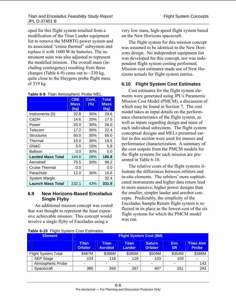
Titan and Enceladus Feasibility Study Report Flight System Concepts JPL D-37401 B
6-6 Pre-decisional — For Planning and Discussion Purposes Only
oped for this flight system resulted from a modification of the Titan Lander equipment list to remove the MMRTG power system and its associated “cruise thermal” subsystem and replace it with 1600 W-hr batteries. The in-strument suite was also adjusted to represent the modified mission. The overall mass (in-cluding contingency) resulting from these changes (Table 6-9) came out to ~330 kg, quite close to the Huygens probe flight mass of 319 kg.
Table 6-9 Titan Atmospheric Probe MEL. CBE
Mass (kg)
Cont. (%)
Total Mass (kg)
Instruments (5) 22.8 30% 29.6 C&DH 14.6 20% 17.5 Power 20.0 30% 26.0 Telecom 17.2 30% 22.4 Structures 50.0 30% 65.0 Thermal 15.0 30% 19.5 GN&C 5.0 15% 5.8Balloon 0.0 30% 0.0Landed Mass Total 144.6 28% 185.8 Aeroshell 75.5 30% 98.2 Cruise Thermal 0.0 0.0Parachute 12.0 30% 15.6 System Margin 32.4 Launch Mass Total 232.1 43% 331.9
6.9 New Horizons-Based Enceladus Single Flyby
An additional mission concept was costed that was thought to represent the least expen-sive achievable mission. This concept would involve a single flyby of Enceladus using a
very low mass, high-speed flight system based on the New Horizons spacecraft.
The flight system for this mission concept was assumed to be identical to the New Hori-zons design. No independent equipment list was developed for this concept, nor was inde-pendent flight system costing performed. Mission cost estimates made use of New Ho-rizons actuals for flight system entries.
6.10 Flight System Cost Estimates Cost estimates for the flight system ele-
ments were generated using JPL’s Parametric Mission Cost Model (PMCM), a discussion of which may be found in Section 7. The cost model takes as input details on the perform-ance characteristics of the flight system, as well as inputs regarding design and mass of each individual subsystem. The flight system conceptual designs and MELs presented ear-lier in this section were used for masses and performance characterization. A summary of the cost outputs from the PMCM models for the flight systems for each mission are pre-sented in Table 6-10.
The relative costs of the flight systems il-lustrate the differences between orbiters and in-situ elements. The orbiters’ more sophisti-cated instruments and higher data return lead to more massive, higher power designs than the smaller, simpler lander and aerobot con-cepts. Predictably, the simplicity of the Enceladus Sample Return flight system is re-flected in its place as the lowest cost of the six flight systems for which the PMCM model was run.
Table 6-10 Flight System Cost Estimates. Element Flight System Cost ($M)
Titan Orbiter
Titan Aerobot
Titan Lander
Saturn Orbiter
Enc SR
Titan Atm Probe
Flight System Total $487M $386M $385M $509M $354M $386M SEP Stage 103 118 118 103 103 - Atmospheric Probe - - - - - 143 Spacecraft 385 269 267 407 251 243

Titan and Enceladus Feasibility Study Report Flight System Concepts JPL D-37401 B
6-2 Pre-decisional — For Planning and Discussion Purposes Only
This page intentionally left blank

Titan and Enceladus Feasibility Study Report Ground System JPL D-37401 B
7-1 Pre-decisional — For Planning and Discussion Purposes Only
7. Ground System
7.1 Overview Missions to the outer solar system planets
present major challenges in the mission opera-tions phase, which drive costs to levels be-yond those experienced typically with inner solar system missions. First, mission times are always long and include extensive cruise phases some of which involve gravity assist maneuvers in the inner solar system. Second, communications distances are very large at the target destination, which impacts both achiev-able data rates, and command latency, which in turn drives mission operations complexity. To deal with the data rate challenge, it may be necessary to commit a significant fraction of DSN resources in order to acquire the data return, which the mission objectives require. Pre-planning and on board autonomy are ef-fective methods used to deal with command latency.
In this section, the approach used to assess cost of the Ground System (composed of Mis-sion Operations System and Ground Data Sys-tem) as well as unique cost drivers are dis-cussed.
7.2 Introduction A summary of the seven Titan and Encela-
dus mission concepts and related mission op-erations drivers are shown in Table 7-1. All estimates are built upon approaches used on ongoing and planned outer solar system plane-tary missions: the Flagship class mission Cas-sini-Huygens (Saturn system), and two New Frontiers class missions - New Horizons (Pluto) and Juno (Jupiter). See Appendix A for a detailed functional description of the Ground System. The cost basis is comprised of elements that are common to all mission concepts studied and elements that are unique to each as discussed below
7.3 Common Elements For all options the development period
was assumed to be 5 years with each phase broken into the following durations:
• Phase A: 12 Months • Phase B: 12 Months • Phase C/D: 36 Months, for Ground
cost estimating used Phase C: 16 months, and Phase D: 20 months
• Phase E: Starts at Launch + 30 days and has variable length based on the mission concept
The following assumptions were made in regards to the development tasks:
• MOS workforce levels are scoped to address risk and management profiles consistent with a competed New Fron-tiers class (~$800M+) mission, such as Juno or NH. Relative to Flagship class missions, this results in reduced staffing profiles for development and operations, fewer reviews and layers of oversight and fewer new developments and more customization of existing tools.
• No foreign partnerships or instruments. This minimizes ITAR issues and asso-ciated overhead.
• Science Operations were assumed to be centered at JPL for this exercise. This minimizes new interfaces and re-lated costs.
• JPL performs MOS and GDS devel-opment and mission operations using the existing multi-mission tools and capabilities.
• A full time MOS development man-ager is included during phases A-D and a full time Mission Manager in phase E.

Titan and Enceladus Feasibility Study Report Ground System JPL D-37401 B
7-2 Pre-decisional — For Planning and Discussion Purposes Only
Table 7-1 Mission Options and Operations Drivers. Mission Concept General Description Driving Features Phase E
Titan Orbiter – SEP 7 year cruise to Titan, Aerocapture into orbit, 1 month Aerobraking for atmospheric science, and 2 years or-bital science
Once on science orbit mission becomes very repetitive and routine
109 months (9.1 years)
Titan Aerobot – SEP 7 year cruise to Titan, direct entry into atmosphere, 12 months of aerobot operations
Directing the aerobot is compa-rable to MER operations with very short turn around times
95 months (7.9 years)
Titan Lander – SEP 7 year cruise to Titan, direct entry onto surface, 3 months of heavy surface operations, 21 months of meteorology operations
After prime science can reduce to almost minimal operations staff
107 months (8.9 years)
Enceladus Sample Return – SEP
7 year cruise to Enceladus, fly-by of the plume to collect sample, 11 year return cruise
Very long and quiet cruise per-mits low staffing and minimal DSN
215 months (17.9 years)
Saturn Orbiter with Multiple Enceladus Fly-bys – SEP
7 year cruise to Saturn, enter into orbit around Saturn, Fly-by Enceladus roughly every 12 days for 2 years, for a total of 42 fly-bys
Fly-bys every twelve days cre-ates very busy operating envi-ronment
107 months (8.9 years)
Enceladus Single Fly-by – Chemical Propul-sion
4 year direct trajectory to Enceladus, short fly-by followed by 3 months of science data return
Direct trajectory permits very short cruise and limited science collection period - hours
51 months (4.25 years)
Titan Atmospheric Probe – Chemical Pro-pulsion
11 year trajectory to Saturn, fly-by spacecraft provides data relay for probe that performs direct entry into Titan’s atmosphere, hours of science taking and 2 8-hour DSN passes for data return
Long quiet cruise and limited science collection period - hours
133 months (11 years)
• A half time GDS development man-
ager is estimated throughout develop-ment. Since all development is planned to be completed prior to launch, funding for the GDS manager ends after launch (any additional post launch development activities would be managed by the Mission Manager).
• Existing multi-mission GDS is used with tailoring of sequence and plan-ning tools and telemetry displays to meet mission specific needs.
• GDS deliveries during development occur every 6 months starting ~3 months prior to ARR, which coincides with one of the first deliveries of the flight software. This delivery cycle follows the pattern established over the last several missions and reflects
phased delivery and integration of ma-jor functionality.
• Post-launch GDS deliveries occur every 18 months to keep in sync with the multi-mission common delivery schedule.
• JPL staff is responsible for limited in-strument operations and data process-ing.
• JPL staff performs instrument com-manding and health monitoring (versus an instrument provider). The science team performs the target selection and data analysis.
• JPL staff performs the processing of instrument telemetry data to level 0’ (i.e., the raw telemetry data stream is decommutated to return it the format it was in on board the spacecraft prior to

Titan and Enceladus Feasibility Study Report Ground System JPL D-37401 B
7-3 Pre-decisional — For Planning and Discussion Purposes Only
transmission). Relevant spacecraft context information is provided to aid in the data analysis.
• Science team members perform data processing beyond level 0’.
• JPL staff archives level 0’ data into the PDS.
• Minimal hardware procurements con-sistent with what is required to support NF class missions. − 1 MSA suite (15 workstations, 2
servers) − 1 GDS test bed support suite (5
workstations, 2 servers) − 1 GDS ATLO support suite (4
workstations, 1 server) − Maintenance/replenishment
throughout life of mission
7.4 Unique Elements The first five mission concepts shown in
Table 7-1 follow a similar trajectory and there-fore assume the same staffing profile for the cruise to Saturn. This trajectory includes 3 years of continuous solar electric propulsion (SEP) thrusting including at least one Earth gravity assist, followed by roughly 4 years of ballistic coasting to arrive at Saturn.
During the 3 years of SEP operations the spacecraft team is maintained at regular staff-ing levels, to support thrusting operations, se-
quence updates, and health monitoring. Also during this period the tracking is averaging two 8-hour passes per week to support naviga-tion and general health monitoring and com-manding. In addition once per year, through out cruise, a weeklong health check is per-formed with daily tracking passes.
At the end of SEP operations the space-craft enters into a quiet ballistic coast phase lasting 3.25 years. During this period very little is performed and the general spacecraft activity is low including an annual health veri-fication. For this period the spacecraft team is reduced to minimum levels and the tracking is held to one 8-hour pass every two weeks.
The last 9 months of cruise is spent pre-paring for the encounter and science activities. This involves ramping up the spacecraft team and performing the related training and opera-tional readiness testing. In addition, long-range observations are assumed to occur in preparation for the encounter and increased tracking is included to support navigation analysis for orbit insertion or targeted entry.
The DSN profile common to these five missions is shown in Table 7-2. The follow-ing sections discuss unique aspects of the mis-sions studied and the specific DSN utilization assumptions as shown in tables 7-3 through 7-9.
Table 7-2 Common DSN Profile. DSN Profile used Antenna Op year Hrs/pass Pass/wk # weeks
1 LEOP 34BWG 2018-2025 8 21.0 4.02 Cruise Nav & health checks 34BWG 2018-2025 8 2.0 147.03 Annual check-outs (x7) 34BWG 2018-2025 8 7.0 7.04 EEGA 34BWG 2018-2025 8 20.0 2.05 Cruise Quiet 34BWG 2018-2025 8 0.5 179.06 Prep for Encounter Cruise 34BWG 2018-2025 8 2.0 20.07 Approach-Hvy Track 34BWG 2018-2025 8 21.0 3.07 DDOR 34BWG 2018-2025 4 4.0 3.08 Approach + Science 34BWG 2018-2025 8 14.0 3.08 DDOR 34BWG 2018-2025 4 2.0 3.09 Orbit Insert 70 2025 8 3.0 1.09 Orbit Insert 34BWG 2025 8 11.0 1.0

Titan and Enceladus Feasibility Study Report Ground System JPL D-37401 B
7-4 Pre-decisional — For Planning and Discussion Purposes Only
Table 7-3 Titan Orbiter Details. Titan Orbiter Antenna Op year Hrs/pass Pass/wk # weeks
10 Aerobrake 34BWG 2025 8 21 4
11 Orbit Science 34BWG 2025-2027 8 7 108
Table 7-4 Titan Aerobot Details. Titan Aerobot Antenna Op year Hrs/pass Pass/wk # weeks
9 Aerobot EDL 70 2025 8 3 1
9 Aerobot EDL 34BWG 2025 8 11 1
10 Aerobot Science 70 2025-2026 8 14 22
11 Aerobot Science 70 2025-2026 8 4 23
7.4.1 Titan Orbiter The Titan Orbiter uses aerocapture to
achieve an eccentric orbit around Titan fol-lowed by aerobraking to enable atmospheric science. Once the final orbit is achieved, the system performs relatively simple repetitive observations. The initial observations last three months during which a regular operating routine is established and the operating envi-ronment is characterized. This permits reduc-ing the spacecraft team for the remaining 21 months of remote observational science as shown in Table 7-3.
7.4.2 Titan Aerobot The Titan Aerobot mission delivers an
aerobot (Montgolfiere hot air balloon) directly into Titan’s atmosphere. After deployment, the aerobot drifts with the atmosphere at con-trolled altitudes. By changing altitudes the direction of the aerobot can be modified, per-mitting some directional control and in turn the ability to target specific features and re-gions for observation. Since the aerobot is always moving, the ability to stop and plan an observation does not exist; instead the operat-ing tempo is comparable to MER without the ability to pause. To support this mission, new planning tools will need to be developed. The
science mission duration is12 months, with an observation cycle of 9 days on and 7 days off. This cycle reflects Titan’s sidereal rotation and aerobot communication opportunities. Given the communication system on the aerobot, two 8-hour passes per day to a DSN 70-m station (or equivalent) are required during the 9 days out of 16 that communication is possible. Be-cause of the difficulty of pre-pointing the communication antenna from the aerobot, a beacon tone from the DSN station performing the tracking needs to be transmitted prior to the data return starts. This beacon tone en-ables the aerobot communication system to point to and acquire the DSN station. DSN utilization details unique to this mission are shown in Table 7-4.
7.4.3 Titan Lander This mission option directly delivers a lan-
der to a targeted area on the surface of Titan. This lander has been described as being Mars Viking-like in the nature of science collection activities. The primary science activities last for 3 months during which images are taken, samples are collected and analyzed, and the surface is characterized. After 3 months the science is reduced to meteorology for the re-maining 21 months.

Titan and Enceladus Feasibility Study Report Ground System JPL D-37401 B
7-5 Pre-decisional — For Planning and Discussion Purposes Only
Table 7-5 Titan Lander Details. Titan Lander Antenna Op year Hrs/pass Pass/wk # weeks
9 Lander EDL 70 2025 8 3 1
9 Lander EDL 34BWG 2025 8 11 1
10 Lander Science 70 2025 8 14 6
11 Lander Science 70 2025 8 4 5
12 MET Science 70 2025-2026 8 0.875 91
During the prime science phase spacecraft team support is heavy and two 8-hour passes per day (for the 9 out of 16-day communica-tion cycle) to a DSN 70-m station (or equiva-lent) are conducted to return all of the col-lected data through the low power communication system. See Figure 7-5. Similar to the aerobot, a beacon tone from the DSN is required for the initial contact, after which predicts and ephemera can be uploaded to support future communication activities.
7.4.4 Enceladus Sample Return This mission collects plume samples from
the south polar region of Enceladus and deliv-ers them back to Earth for analysis. This is the simplest to operate and longest mission of the set. The mission critical sample collection
fly-by event requires careful planning and preparation, full spacecraft team staffing, and heavy navigation support. However once the samples are captured, the spacecraft can be put into hibernation for the return trip up until 6 months prior to Earth entry. Preparation for Earth entry will at least be comparable to that of Genesis or Stardust, with a ramp up of spacecraft team, navigation, and mission plan-ning support at least 6 months prior to entry. Details specific to DSN utilization costs for this mission are shown in table 7-6
Though this is the longest mission of the set, and the overall MOS costs reflect that, the average level of effort is the lowest as are the DSN tracking costs.
Table 7-6 Enceladus Sample Return Details. Enceladus Sample Return Antenna Op year Hrs/pass Pass/wk # weeks
9 Fly by week 70 2025 8 3 1
9 Fly by week 34BWG 2025 8 11 1
10 Fly by Science return 34BWG 2025 8 7 4
11 prep for return cruise 34BWG 2025 8 4 5
12 Cruise Nav & health checks 34BWG 2025-2032 8 2 4
13 Annual check-outs (x7) 34BWG 2025-2032 8 7 7
15 Cruise Quiet 34BWG 2025-2032 8 0.5 527
16 Prep for EDL 34BWG 2032 8 2 20
17 Approach-Hvy Track 34BWG 2032 8 21 3
19 Approach + Lt trking 34BWG 2032 8 14 3

Titan and Enceladus Feasibility Study Report Ground System JPL D-37401 B
7-6 Pre-decisional — For Planning and Discussion Purposes Only
Table 7-7 Saturn Orbiter with multiple Enceladus Fly-bys Details. Enceladus Fly-by Antenna Op year Hrs/pass Pass/wk # weeks
9 Orbit Insert 70 2025 8 3 1
9 Orbit Insert 34BWG 2025 8 11 1
10 Orbit Science 34BWG 2026-2026 8 7 104
Table 7-8 Enceladus Single Fly-by Details. Enceladus New Horizon Fly-by Antenna Op year Hrs/pass Pass/wk # weeks
1 LEOP 34BWG 2018 8 21 4 2 Cruise Nav & health checks 34BWG 2018-2022 8 2 12 3 Annual check-outs (x7) 34BWG 2018-2022 8 7 2 4 TCMs (x4) 34BWG 2018-2022 8 20 4 5 Cruise Quiet 34BWG 2018-2022 8 0.5 164 6 Prep for Encounter Cruise 34BWG 2018-2022 8 2 20 7 Approach-Hvy Track 34BWG 2018-2022 8 21 3 7 DDOR 34BWG 2018-2022 4 4 3 8 Approach + Science 34BWG 2018-2022 8 14 3 8 DDOR 34BWG 2018-2022 4 2 3 9 Fly-by 70 2022 8 3 1 9 fly-by 34BWG 2022 8 11 1
10 return Fly-by Science 34BWG 2022 8 7 13 7.4.5 Saturn Orbiter with Multiple
Enceladus Fly-bys This option delivers a spacecraft that or-
bits Saturn and achieves multiple fly-bys of Enceladus. Because of the nature of the orbit, and the operational tempo, this is likely the most operationally complex concept. Roughly every 12 days a fly-by of Enceladus occurs, usually along a slightly different trajectory requiring updating and coordination of the in-strument pointing and data collection plans and frequent navigation updates. At about the time this might start to get routine the orbit is then altered by use of Titan gravity assists to enable fly-bys over the opposite side of Enceladus. Single daily 8-hour passes to a DSN 34m are used for data return and naviga-tion support as shown in Table 7-7.
7.4.6 Enceladus Single Fly-By This Enceladus mission assumes a New
Horizon-like spacecraft to execute a fast fly-by of Enceladus. The transfer to Saturn takes only 4 years and has few maneuvers permit-ting low levels of staffing throughout the mis-sion. These factors make this the least expen-sive mission in the set to operate. As shown in Table 7-8, heavy tracking is assumed around the fly-by period, followed by daily 8-hour passes for the next 3 months to return all of the collected science data.
7.4.7 Titan Atmospheric Probe This option delivers a Huygens-like probe
to Titan. This option differs from the baseline in two significant ways, it uses a long duration chemical propulsion trajectory and the en-counter is very short. These differences are

Titan and Enceladus Feasibility Study Report Ground System JPL D-37401 B
7-7 Pre-decisional — For Planning and Discussion Purposes Only
illustrated in Table 7-9, describing the tracking profile.
Though the cruise is the longest of the op-tions at 11 years, it is generally very quiet and the spacecraft team can be reduced after the first year of cruise. Then roughly six months before each Earth gravity assist the team is increased to support the activity and then re-duced shortly afterwards.
The preparation for encounter is similar to the other options, but the actual encounter lasts a couple months. The encounter starts a month prior to reaching Titan and includes the deployment of the probe and playback by the fly-by spacecraft of the probe data.
The Probe entry and science collection co-incides with the fly-by and is tracked by both 70-m and 34-m DSN antennas ensure ade-quate coverage for navigation and quick first look data return. The actual period of science collection and relay to the fly-by spacecraft lasts only a few hours. After the fly-by sev-eral weeks of daily passes are scheduled for repeated playback to ensure all of the data col-lected is returned.
The very simple spacecraft keep develop-ment and operating costs low. The spacecraft is a carrier and relay for the probe, without any instruments of note. The probe is pro-grammed prior to launch, with the provision that event timing can be updated prior to de-ployment, but little else is modifiable. These two items make operating the spacecraft very simple and enable a minimal team, making this the lowest cost Titan mission in the set even though it is one of the longer missions.
7.5 Ground System Cost Summary Ground System (MOS/GDS) cost esti-
mates were developed using JPL’s Ground Segment Team (GST) cost models. See Ap-pendix A for a more detailed functional de-scription of the Ground System. The GST models have undergone V&V and have dem-onstrated to be within 20% or better of actual costs for a broad range of missions. The model produces results consistent with the current JPL practices and cost guidelines. All MOS/GDS estimates in this report are in fixed year FY06$. These estimates are intended to be used for pre-decisional planning only.
Table 7-9 Titan Atmospheric Probe Details. Titan Atmospheric Probe Antenna Op year Hrs/pass Pass/wk # weeks
1 LEOP 34BWG 2018 8 21 4 2 Cruise Nav & health checks 34BWG 2018-2029 8 2 78 3 Annual check-outs (x7) 34BWG 2018-2029 8 7 9 4 Multiple GA + 2x DSM 34BWG 2018-2029 8 20 4 5 Cruise Quiet 34BWG 2018-2029 8 0.5 376 6 Prep for Encounter Cruise 34BWG 2018-2029 8 2 20 7 Approach-Hvy Track 34BWG 2018-2029 8 21 3 7 DDOR 34BWG 2018-2029 4 4 3 8 Approach 34BWG 2018-2029 8 14 3 8 DDOR 34BWG 2018-2029 4 2 3 9 Fly-by 70 2029 8 3 1 9 Fly-by 34BWG 2029 8 11 1
10 Additional data return 34BWG 2029 8 7 4

Titan and Enceladus Feasibility Study Report Ground System JPL D-37401 B
7-8 Pre-decisional — For Planning and Discussion Purposes Only
The estimate follows the standard JPL WBS: MOS and GDS cover WBS element 07.xx and 09.xx. Per this WBS the Naviga-tion and Mission Planning Development is estimated under WBS 12.x by the Mission de-signer and is not included in the MOS/GDS
estimate. However, all phase E costs for Mis-sion Design and Navigation are estimated un-der WBS 07.x by the Mission designer and inserted in the MOS estimate.
A summary of MOS costs is shown for each of the missions in Table 7-10.
Table 7-10 Mission Operations Cost Summary.
Option Development Cost
Operations/ DSN Cost
Discussion
Titan Orbiter – SEP $ 31.4 M $ 67.0 M $ 26.3 M
Small uppers for operations preparation. Routine orbit activities keep operations cost in line.
Titan Aerobot – SEP $ 32.7 M $ 63.5 M $ 44.4 M
Complex operating scenario requires new planning tool development and heavier staffing during science
Titan Lander – SEP $ 31.1 M $ 57.8 M $ 23.7 M
Floor mission for MOS/GDS costs. Once landed several members of S/C team can be released, once MET mis-sion started team can be further reduced
Enceladus Sample Return – SEP
$ 31.6 M $114.6 M $ 19.4 M
Slight upper in development for Earth EDL planning and coordination. Most expensive operations because of very long mission, but overall very low staffing and light tracking during cruise keep monthly operations costs low.
Saturn Orbiter with Multiple Enceladus Fly-bys – SEP
$ 32.4 M $ 77.6 M $ 23.5 M
Additional instruments (+2) increase development costs, complexity of repeated fly-bys increase operations cost
Enceladus Single Fly-by – Chemical Propulsion
$ 32.4 M $ 27.5 M $ 11.5 M
Direct trajectory cuts down mission duration reducing overall costs, More work required up front to handle fly-by critical event and fault protection planning
Titan Atmospheric Probe – Chemical Propulsion
$ 28.3 M $ 51.7 M $ 14.5 M
Very Long quiet cruise, simple spacecraft with probe, and a short encounter all contribute to inexpensive develop-ment and operations. The actual timing of the fly-by co-ordination is challenging and affects staffing levels, how-ever the overall mission costs remain low

Titan and Enceladus Feasibility Study Report Cost Assessment JPL D-37401 B
8-1 Pre-decisional — For Planning and Discussion Purposes Only
8. Cost Assessment
8.1 Cost Assessment Overview The objective of this study was to de-
termine the feasibility of scientifically worthwhile missions that can be imple-mented within a $1B FY’06 cost cap. Seven mission concepts (four Titan missions and three Enceladus missions) were selected for development of life cycle cost estimates. Science and payloads, architectural con-cepts, flight systems and MOS/GDS designs that were used as the basis of the cost esti-mates are discussed in earlier sections of this document. The selected mission options that were costed are: 1) Titan Orbiter 2) Titan Aerobot 3) Titan Lander 4) Titan Atmospheric Probe 5) Saturn Orbiter/Multiple Enceladus Fly-
Bys 6) Enceladus Plume Sample Return 7) Enceladus Single Fly-by
8.2 Cost Model Description Cost estimates were developed using
JPL’s Outer Planet Mission Cost Model (OPMCM). OPMCM is a hybrid cost model integrating existing cost models. Wrap fac-tors based upon JPL historic averages were used for WBS elements 01 Project Man-agement, 02 Project Systems Engineering and 03 Safety and Mission Assurance. Esti-mates for WBS 04 Science were scaled from the value of the payload system per historic averages. The beta version of the NASA In-strument Cost Model (NICM) was used to estimate WBS 05 Payload System instru-ments for each mission option. Instrument management, systems engineering, product assurance and payload integration and test
costs were included in each instrument cost estimate. WBS 06 Flight Systems and 10 Project Systems I&T costs were estimated using JPL’s Parametric Mission Cost Model (PMCM) and the JPL Assembly, Test and Operations Cost Model (JACM) respec-tively. PMCM and JACM are internal JPL cost models routinely used in Step 1 and Step 2 AO proposal cost comparisons. The Department of Energy provided RPS cost estimates for the MMRTG and GPHS RTG options. WBS 07 MOS and 08 GDS costs were developed using JPL’s Ground Seg-ment Team cost model using a parametric-grassroots methodology. A $10M estimate for WBS 11 Education and Public Outreach was used. WBS 12 Mission Design cost es-timates were generated using a parametric-grassroots approach. All costs are consistent with version 4 of the JPL Standard Work Breakdown Structure (WBS) and dictionary. This WBS provides the structure for all cost estimation and reporting. The cost estimates are life cycle, and include the Radioisotope Power Source, launch system and DSN ap-erture fees. All launch system costs include estimates for nuclear handling associated with the radioisotope power sources. Table 8-1 provides a description of the model used at level 2 of the WBS. All final cost esti-mates have been reviewed by the science and engineering team members as well as the expert advisory team and additional ex-perts external to the study.
Reserves and range of uncertainty were calculated based upon the perceived cost risk and associated design uncertainty for each mission using the approach illustrated in Figure 8-1. A discussion of how the re-serves and uncertainty were determined fol-lows and Table 8-2 summarizes these results for each mission option.

Titan and Enceladus Feasibility Study Report Cost Assessment JPL D-37401 B
8-2 Pre-decisional — For Planning and Discussion Purposes Only
-Total Mission CostTMC = CBE Cost + Reserves (A) + Reserves (B) + (LV + LV Reserves) where
Reserves (A) = A1*[A-D CBE Cost] + A2*[E CBE Cost]Reserves (B) = B1*[A-D CBE Cost] + B2*[E CBE Cost]
-Range of UncertaintyUpper limit = TMC + (C1+D)*CBE CostLower limit = TMC + C2*CBE Cost
Design Maturity Reserves
CBE Cost
LV + LV Capability Margin
Uncertainty Range associated with cost uncertainty and technical implementationvariation
Subfactors reserve Cost RiskTMC
Figure 8-1 Total Mission Cost.
Table 8-1 Cost Model Description. WBS Model Description 01 Project Management Wrap factor based upon recent proposals and historic cost data analysis 02 Project System Engineering Wrap factor based upon recent proposals and historic cost data analysis 03 Safety & Mission Assurance Wrap factor based upon recent proposals and historic cost data analysis 04 Science Team Scaled form historic cost data relationship between Science Team and
instrument costs 05 Payload System NASA Instrument Cost Model (NICM), analogy, Science Team evalua-
tion 06 Spacecraft System JPL Parametric Mission Cost Model (PMCM) Radioisotope Power System RPS prices provided by DOE 07 Mission Operations System JPL Ground Segment Team Cost Model 08 Launch System w/ Nuclear Support KSC deflated to $FY06 using NASA inflation rates 09 Ground Data System JPL Ground Segment Team Cost Model DSN Aperture JPL Ground Segment Team Cost Model 10 Project System Integration & Test JPL Assembly, Test and Operations Cost Model (JACM) 11 Education and Public Outreach Scaled at $10 FY06M 12 Mission Design JPL Mission Design Cost Model Reserves JPL Cost Risk Subfactors and design maturity evaluation
To calculate reserves for each of the
missions under study, the JPL Cost Risk Subfactor analysis was used to identify the minimum budget reserve requirements for each mission assuming a Phase B (prelimi-nary design) level of concept maturity. Eight criteria (e.g., mission complexity, sys-tem architecture) each with lower level
characteristics (e.g., multiple flight ele-ments, new system architecture) were rated according to primary and secondary risk subfactors. Reserves were calculated using a base level of 20% with each primary sub-factor adding 5% and each secondary sub-factor adding 2%. Operations phase reserves were held at 15%. Results are shown in

Titan and Enceladus Feasibility Study Report Cost Assessment JPL D-37401 B
8-2 Pre-decisional — For Planning and Discussion Purposes Only
Table 8-2, Row A. Each mission option was then evaluated for additional design maturity risk associated with the fact that the con-cepts under study (pre-Phase A level of ma-turity) were much less mature than what would be expected at the start of Phase B Preliminary Design. That evaluation estab-lished an additional increment of reserves to be included in the overall reserves pool. Fi-nally, a launch capability reserve (or contin-gency) was established to mitigate the risk associated with the low maturity of flight system mass estimates. This was estimated as the difference in cost between the se-lected launch capability and the next higher level of performance. As shown in Figure 8-1, all three elements were added to the cur-rent best estimate (CBE) to form the TMC.
The uncertainty range (upper and lower ends) of the cost estimate was determined by adding the uncertainty associated with the cost models (Table 8-2, Row C) with uncer-tainty associated with degree of difficulty associated with technical implementation of each concept (Table 8-2, Row D) as shown in Figure 8-1.
It is important to acknowledge that while the TMC estimates do consider development risk in the reserves model, they do not ac-count for mitigation of all risks. Costs for technology maturation through flight readi-ness (NASA definition of TRL6) and for a small subset of development tasks that could not be accurately quantified within the lim-ited timeframe and scope of this study have been identified as liens against the estimated costs as shown in Section 1.6, Figure 1-3.
Figure 8-2 shows a comparison of Total Mission Costs and uncertainty ranges for each of the mission costed as part of this study. All costs are reported in $FY06M.
8.3 Cost Estimate Comparison A comparison of each mission reported
at WBS level 2 is given in Table 8-3 with detail for provided in Tables 8-4 through 8-
10. Since the Enceladus Single Fly-By mis-sion assumed the NH flight system, its costs were derived from the NH WBS based his-torical costs. Because the NH WBS and the breakout used for this study differed signifi-cantly, values for the Enceladus Single Fly-By mission in Table 8-3 cannot be compared with the other missions directly.
Of the seven (7) missions costed for fea-sibility, the Titan Atmospheric Probe and Enceladus Single Fly-By missions margin-ally meet the cost cap but fall short of the science guidelines. The remaining 5 mis-sions exceed the cost cap significantly be-cause they require more complex architec-tures to implement.
The Titan Orbiter and Saturn Orbiter missions have the highest costs of the mis-sion options. The primary cost driver for these missions is the data intensive science payloads necessary to achieve science re-turns above Cassini-Huygens. This results in more capable instruments associated higher data rate and power demands. This all leads to high relative costs. These orbiter missions have relatively lower implementation and operation risks because of the large body of experience. This risk is reflected in Table 8-2 for category (A1) Development Risk.
The Enceladus Sample Return includes a minimal science payload and Stardust type sample capture and return system. The sim-pler science payloads have smaller data rate and power demands leading to lower relative costs. This mission has higher implementa-tion and operation risks due to the unique-ness and uncertainty associated with the high particle capture velocity at Enceladus (>10 km/s compared to Stardust at 6 km/s), long mission life time (>18 years) and lim-ited experience base. These risks result in the relatively high values reported in Table 8-2 for category (A1) Development Risk.

Titan and Enceladus Feasibility Study Report Cost Assessment JPL D-37401 B
8-3 Pre-decisional — For Planning and Discussion Purposes Only
Table 8-2 Reserves and Uncertainty model are consistent with maturity of study. Reserves are indicated by shading.
Titan Orbiter
Titan Aerobot
Titan Lander
Saturn Orbiter Enc. Fly-by
Enceladus SR
Titan Atm Probe
Enceladus Single Fly-
By Reserves and Uncertainty A: JPL Cost Risk Subfactor Analysis Cost risk evaluation using JPL process for Phase B/C/D Risk Assessment. Covered in Pro-ject Reserves.
A1: Development Phase 31% 44% 38% 31% 44% 24% 24%
A2: Operations Phase 15% 15% 15% 15% 15% 15% 15% B: Design Maturity (Knowl-edge of existing design) Understanding of technical design and potential changes from concept study to PMSR. Covered in Project Reserves
B1: Development Phase 15% 30% 30% 15% 20% 10%
B2: Operations Phase 5% 5% 5% 5% 5% 0% C: Cost Variation Uncertainty of cost estimate based on comparison with historic actuals or cost analo-gies
C1: All Phases (Upper) 30% 30% 30% 30% 30% 30% 10%
C2: All Phases (Lower) -5% -5% -5% -5% -5% -5% 0% D: Difficulty of technical implementation (Under-standing of implementation) E.g., Aerocapture in the Titan atmospheric environment
D: All Phases 4% 20% 20% 4% 15% 0% 0%
E: Technology Liens (Reported separately) All Phases Uncosted Uncosted Uncosted Uncosted Uncosted Uncosted Uncosted

Titan and Enceladus Feasibility Study Report Cost Assessment JPL D-37401 B
8-4 Pre-decisional — For Planning and Discussion Purposes Only
800
1000
1200
1400
1600
1800
2000
Titan Orbiter Titan Aerobot Titan Lander Saturn OrbiterEnc. Fly-by
Enceladus SR Titan Atm.Probe
EnceladusSingle Fly-by
$FY0
6M
TMC
- Technology Liens not included- Contingency applied to account for uncertainty at this early stage- Costs of Titan & Saturn Orbiter missions are higher than in-situ and sample return missions due to more data-intensive payload suites needed to acquire science beyond Cassini. This leads to more capable instruments, higher data rates and a more massive, higher power design.
Science value below guideline
Figure 8-2 Mission Option Total Mission Cost with Range.

Titan and Enceladus Feasibility Study Report Cost Assessment JPL D-37401 B
8-5 Pre-decisional — For Planning and Discussion Purposes Only
Table 8-3 Total Mission Cost Comparison.
Titan Orbiter
Titan Aerobot
Titan Lander
Saturn Orbiter Enc. Fly-by
Enceladus SR
Titan Atm. Probe
Enceladus Single Fly-by
01 Project Management 35 26 27 34 27 24 In WBS 06 02 Project System Engineering 30 23 23 29 24 20 In WBS 06 03 Safety & Mission Assurance 40 30 31 38 31 27 In WBS 06 04 Science Team 83 42 54 58 49 32 40 05 Payload System 156 65 102 109 92 60 75 06 Spacecraft System 323 294 293 345 262 294 220 Radioisotope Power System 164 92 92 164 92 92 92 07 Mission Operations System 74 72 64 83 114 56 60 09 Ground Data System 25 24 25 27 32 24 In WBS 07 DSN Aperture 26 44 24 23 19 14 11 10 Project System Integration & Test 23 20 20 25 21 15 18 11 Education and Public Outreach 10 10 10 10 10 10 In WBS 06 12 Mission Design 9 7 8 13 11 13 In WBS 06 CBE Cost (Reserves Base) 997 750 773 960 786 681 517 Reserves 413 468 459 399 418 212 114 08 Launch System w/ Nuclear Support 166 139 139 175 166 175 194 LV Reserve 10 27 27 19 10 19 N/A Total Mission Cost ($FY06M) 1,586 1,384 1,397 1,553 1,378 1,087 826

Titan and Enceladus Feasibility Study Report Cost Assessment JPL D-37401 B
8-6 Pre-decisional — For Planning and Discussion Purposes Only
Table 8-4 Titan Orbiter Cost Summary.
Phase A/B Phase C/D Phase E Total ($FY06)
Phase Duration (Months) 24 36 109 01 Project Management 3 26 6 35 02 Project System Engineering 3 22 5 30 03 Safety & Mission Assurance 4 29 7 40 04 Science Team 6 16 60 83 05 Payload System 16 140 0 156 2 Micron Imager 3 28 31 Plasma package (orbiter only) 3 28 31 Imaging Radar / Altimeter 6 53 59 Chemical Analyzer 3 27 30 Radio Science 1 5 6 06 Spacecraft System 49 439 0 487 06.01 S/C Management 1 12 13 06.02 Spacecraft System Engineering 2 17 19 06.03 Spacecraft Product Assurance Included in WBS 03 0 06.04 Power SS 17 156 174 Power SS 1 9 10 Radioisotope Power System 16 148 164 06.05 C&DH SS 1 13 15 06.06 Telecom SS 2 22 24 06.07 Mechanical SS 3 30 33 06.08 Thermal SS 4 40 45 06.09 Propulsion SS 1 11 12 06.10 GN&C SS 2 21 24 06.11 Harness In 06.07 Mechanical 0 06.12 FSW 1 11 12 06.13 SC M&P In 06.07 Mechanical 0 06.14 SC Testbeds 1 13 14 06.20 SEP 10 92 103 07 Mission Operations System 1 15 58 74 09 Ground Data System 2 13 9 25 DSN Aperture 0 2 24 26 10 Project System Integration & Test 0 23 23 11 Education and Public Outreach 1 3 6 10 12 Mission Design 4 6 9 CBE Cost (Reserves Base) 88 734 176 997 Reserves 40 338 35 413 08 Launch System w/ Nuclear Support 17 149 166 LV Reserve 1 9 10 Total Mission Cost ($FY06) 145 1,229 211 1,586

Titan and Enceladus Feasibility Study Report Cost Assessment JPL D-37401 B
8-7 Pre-decisional — For Planning and Discussion Purposes Only
Table 8-5 Titan Aerobot Cost Summary.
Phase A/B Phase C/D Phase E Total ($FY06)
Phase Duration (Months) 24 36 95 01 Project Management 2 18 6 26 02 Project System Engineering 2 16 5 23 03 Safety & Mission Assurance 2 21 6 30 04 Science Team 3 7 33 42 05 Payload System 7 59 0 65 Survey Camera Suite 0 4 5 Met Package 1 5 5 Profiling/Subsurface Radar 2 15 17 Gas Chromatograph Mass Spectrometer 4 32 35 TDL Spectrometer (ethane, methane, HCN) 0 4 4 06 Spacecraft System 39 348 0 386 06.01 S/C Management 1 8 9 06.02 Spacecraft System Engineering 1 12 13 06.03 Spacecraft Product Assurance Included in WBS 03 0 06.04 Power SS 10 91 101 Power SS 1 8 9 Radioisotope Power System 9 83 92 06.05 C&DH SS 1 11 13 06.06 Telecom SS 2 16 18 06.07 Mechanical SS 3 24 27 06.08 Thermal SS 2 20 22 06.09 Propulsion SS 0 0 0 06.10 GN&C SS 3 26 29 06.11 Harness In 06.07 Mechanical 0 06.12 FSW 2 19 22 06.13 SC M&P In 06.07 Mechanical 0 06.14 SC Testbeds 1 13 15 06.20 SEP 12 106 118 07 Mission Operations System 1 15 55 72 09 Ground Data System 2 14 9 24 DSN Aperture 0 2 42 44 10 Project System Integration & Test 0 20 20 11 Education and Public Outreach 1 3 6 10 12 Mission Design 3 5 7 CBE Cost (Reserves Base) 61 528 161 750 Reserves 45 391 32 468 08 Launch System w/ Nuclear Support 14 125 139 LV Reserve 3 24 27 Total Mission Cost ($FY06) 123 1,068 193 1,384

Titan and Enceladus Feasibility Study Report Cost Assessment JPL D-37401 B
8-8 Pre-decisional — For Planning and Discussion Purposes Only
Table 8-6 Titan Lander Cost Summary.
Phase A/B Phase C/D Phase E Total ($FY06)
Phase Duration (Months) 24 36 107 01 Project Management 2 20 5 2702 Project System Engineering 2 17 4 2303 Safety & Mission Assurance 3 23 6 3104 Science Team 4 10 40 5405 Payload System 10 92 0 102Chemical Analyzer with Surface Sampling 7 66 73Lander Camera 1 5 5Seismometer 2 14 16Met Package 1 5 5Descent Camera 0 3 306 Spacecraft System 39 347 0 38506.01 S/C Management 1 8 906.02 Spacecraft System Engineering 1 12 1306.03 Spacecraft Product Assurance Included in WBS 03 006.04 Power SS 10 91 101Power SS 1 8 9Radioisotope Power System 9 83 9206.05 C&DH SS 1 11 1206.06 Telecom SS 2 16 1806.07 Mechanical SS 3 24 2706.08 Thermal SS 2 20 2206.09 Propulsion SS 0 0 006.10 GN&C SS 3 26 2906.11 Harness In 06.07 Mechanical 006.12 FSW 2 19 2206.13 SC M&P In 06.07 Mechanical 006.14 SC Testbeds 1 13 1406.20 SEP 12 106 11807 Mission Operations System 1 14 49 6409 Ground Data System 2 14 9 25DSN Aperture 0 2 21 2410 Project System Integration & Test 0 20 0 2011 Education and Public Outreach 1 3 6 1012 Mission Design 3 5 8CBE Cost (Reserves Base) 67 567 139 773Reserves 46 385 28 45908 Launch System w/ Nuclear Support 14 125 139LV Reserve 3 24 27Total Mission Cost ($FY06) 129 1,101 167 1,397

Titan and Enceladus Feasibility Study Report Cost Assessment JPL D-37401 B
8-9 Pre-decisional — For Planning and Discussion Purposes Only
Table 8-7 Saturn Orbiter – Enceladus Flyby.
Phase A/B Phase C/D Phase E Total ($FY06)
Phase Duration (Months) 24 36 107 01 Project Management 3 25 6 34 02 Project System Engineering 3 21 5 29 03 Safety & Mission Assurance 3 28 7 38 04 Science Team 4 11 42 58 05 Payload System 11 99 0 109 Visible Imager 2 14 15 Thermal Mapper 2 14 15 Radar sounder 3 23 25 Magnetometer 0 3 3 High-Resolution INMS 3 27 30 Advanced Dust Analyzer 2 14 15 Radio Science 1 5 6 06 Spacecraft System 51 458 0 509 06.01 S/C Management 1 13 14 06.02 Spacecraft System Engineering 2 18 20 06.03 Spacecraft Product Assurance Included in WBS 03 0 06.04 Power SS 17 156 174 Power SS 1 9 10 Radioisotope Power System 16 148 164 06.05 C&DH SS 1 13 15 06.06 Telecom SS 2 22 24 06.07 Mechanical SS 4 33 37 06.08 Thermal SS 4 40 45 06.09 Propulsion SS 2 15 17 06.10 GN&C SS 3 25 28 06.11 Harness In 06.07 Mechanical 0 06.12 FSW 2 15 16 06.13 SC M&P In 06.07 Mechanical 0 06.14 SC Testbeds 2 15 16 06.20 SEP 10 92 103 07 Mission Operations System 1 15 67 83 09 Ground Data System 2 14 11 27 DSN Aperture 0 2 21 23 10 Project System Integration & Test 0 25 0 25 11 Education and Public Outreach 1 3 6 10 12 Mission Design 5 8 13 CBE Cost (Reserves Base) 84 711 164 960 Reserves 39 327 33 399 08 Launch System w/ Nuclear Support 18 158 175 LV Reserve 2 17 19 Total Mission Cost ($FY06) 143 1,213 197 1,553

Titan and Enceladus Feasibility Study Report Cost Assessment JPL D-37401 B
8-10 Pre-decisional — For Planning and Discussion Purposes Only
Table 8-8 Enceladus Sample Return.
Phase A/B Phase C/D Phase E Total ($FY06)
Phase Duration (Months) 24 36 215 01 Project Management 2.2 18.5 6.8 27.50 02 Project System Engineering 2 16 6 24 03 Safety & Mission Assurance 3 21 8 31 04 Science Team 4 9 36 49 05 Payload System 9 83 0 92 Visible Imager 2 14 15 Thermal Mapper 2 14 15 High-Resolution INMS 3 27 30 Advanced Dust Analyzer 2 14 15 Sample Collection System 2 15 17 06 Spacecraft System 35 318 0 354 06.01 S/C Management 1 8 9 06.02 Spacecraft System Engineering 1 11 12 06.03 Spacecraft Product Assurance Included in WBS 03 0 06.04 Power SS 10 91 101 Power SS 1 8 9 Radioisotope Power System 9 83 92 06.05 C&DH SS 1 12 13 06.06 Telecom SS 2 22 24 06.07 Mechanical SS 3 28 31 06.08 Thermal SS 1 7 8 06.09 Propulsion SS 1 11 12 06.10 GN&C SS 2 14 15 06.11 Harness In 06.07 Mechanical 0 06.12 FSW 1 13 14 06.13 SC M&P In 06.07 Mechanical 0 06.14 SC Testbeds 1 10 11 06.20 SEP 10 92 103 07 Mission Operations System 1 15 98 114 09 Ground Data System 2 14 16 32 DSN Aperture 0 2 17 19 10 Project System Integration & Test 0 21 0 21 11 Education and Public Outreach 1 3 6 10 12 Mission Design 4 7 11 CBE Cost (Reserves Base) 64 528 194 786 Reserves 41 338 39 418 08 Launch System w/ Nuclear Support 17 149 166 LV Reserve 1 9 10 Total Mission Cost ($FY06) 122 1,024 232 1,378

Titan and Enceladus Feasibility Study Report Cost Assessment JPL D-37401 B
8-11 Pre-decisional — For Planning and Discussion Purposes Only
Table 8-9 Titan Atmospheric Probe.
Phase A/B Phase C/D Phase E Total ($FY06)
Phase Duration (Months) 24 36 133 01 Project Management 2 18 4 24 02 Project System Engineering 2 15 3 20 03 Safety & Mission Assurance 3 21 4 27 04 Science Team 2 6 23 32 05 Payload System 6 54 0 60 Probe System 0 Met Package 1 5 5 Profiling/Subsurface Radar 2 15 17 Gas Chromatograph Mass Spectrometer 4 32 35 Descent Camera 0 3 3 06 Spacecraft System 39 347 0 386 06.01 S/C Management 1 8 8 06.02 Spacecraft System Engineering 1 11 12 06.03 Spacecraft Product Assurance Included in WBS 03 0 06.04 Power SS 10 91 101 Power SS 1 8 9 Radioisotope Power System 9 83 92 06.05 C&DH SS 1 12 13 06.06 Telecom SS 2 22 24 06.07 Mechanical SS 3 26 29 06.08 Thermal SS 1 8 9 06.09 Propulsion SS 2 18 20 06.10 GN&C SS 1 10 11 06.11 Harness In 06.07 Mechanical 0 06.12 FSW 0 4 5 06.13 SC M&P In 06.07 Mechanical 0 06.14 SC Testbeds 1 9 10 Probe System 14 128 143 07 Mission Operations System 1 13 42 56 09 Ground Data System 2 13 10 24 DSN Aperture 0 2 12 14 10 Project System Integration & Test 0 15 0 15 11 Education and Public Outreach 1 3 6 10 12 Mission Design 5 8 13 CBE Cost (Reserves Base) 63 514 104 681 Reserves 21 175 16 212 08 Launch System w/ Nuclear Support 18 158 175 LV Reserve 2 17 19 Total Mission Cost ($FY06) 103 864 119 1,087

Titan and Enceladus Feasibility Study Report Cost Assessment JPL D-37401 B
8-12 Pre-decisional — For Planning and Discussion Purposes Only
Table 8-10 Enceladus Single Fly-By NH Based Enceladus Fly-by Spacecraft through Phase C/D 220Instruments through Phase C/D 75
Visible Imager 15Thermal Mapper 15High-Resolution INMS 30Advanced Dust Analyzer 15
Science through Phase C/D 2I&T 18MOS/GDS through Phase C/D Reported in S/C Total Observatory 316DOE 92Phase E costs 60Science Phase E 38DSN Aperture 11CBE Cost (Reserves Base) 517Reserves 114ELV 194Boeing-3rd Stage Total ($FY06M) 826
The Titan Atmospheric Probe and
Enceladus Single Fly-by missions fail the science guidelines, but are included in the analysis because it was judged that they provide the lowest cost implementations of missions to Titan or Enceladus. The Titan Atmospheric Probe provides a very simple fly-by spacecraft sized to deliver and pro-vide a data relay for a Huygens-like probe that slowly descends through the Titan at-mosphere. The Enceladus Single fly-by is based on the New Horizons Pluto mission and uses New Horizons as the cost analogy for the spacecraft and associated wrap costs. Costs were adjusted to account for the Enceladus specific science, payload, MOS/GDS, operations, and DSN aperture costs. Both the Titan Atmospheric Probe and Enceladus Single Fly-By missions have low cost uncertainty (Figure 8-2) as well as low implementation and operation risk (Table 8-
2) since the assumed mission systems have been previously flight demonstrated (Huy-gens and NH respectively). Project reserves are held for development risk, but there is no additional reserves increment for design ma-turity.
Figure 8-3 shows a comparison of the mission costs by six areas of aggregation and illustrates differences in science and payload and spacecraft costs. Figure 8-4 shows cost elements for the New Horizons mission (actuals through Phase D and plans for Phase E) and the Juno plan. It should be noted that the New Horizons cost actuals include expended development reserves. The Juno estimate represents a 2011 launch. These two missions provide a benchmark of comparison to the mission options studied with each mission exceeding $800 FY06M.

Titan and Enceladus Feasibility Study Report Cost Assessment JPL D-37401 B
8-13 Pre-decisional — For Planning and Discussion Purposes Only
0
50
100
150
200
250
300
350
400
Titan Orbiter TitanAerobot
Titan Lander SaturnOrbiter Enc.
Flyby
EnceladusSR
Titan Atm.Probe
EnceladusSingle Flyby
$FY0
6M01 Prj Mgmt, 02 PSE, 03 SMA, 11 EPO, 12 Msn Design
04 Science Team + 05 Payload
06 Spacecraft + 10 Sys I&T less RPS
RPS
07 MOS, 09 GDS, DSN Aperture
08 LV
Comparison excludes project and LV reserves
NH Based Flyby not estimated using this
breakdown
Figure 8-3 Mission Option Comparison.
-
100
200
300
400
500
600
700
800
900
1,000
New Horizons (A/B/CD Actuals + EPlan)
JUNO
$FY0
6M
ReservesLaunch SystemScience Phase EPhase E costs w/ DSN ApertureScienceInstrumentsSpacecraft + I&T
Includes RTG
Includes LV + 3rd
Stage
Figure 8-4 Elements for cost for New Horizons and Juno missions.

Titan and Enceladus Feasibility Study Report Summary JPL D-37401 B
9-1 Pre-decisional — For Planning and Discussion Purposes Only
9. Summary
The study objective to determine the fea-sibility of conducting missions to Titan and Enceladus and characterize the science return within a $1B FY06 cost cap was met as de-scribed in Section 1.0, Executive Summary and in the Findings below.
9.1 Findings The following conclusions resulted from
this study: 1. No missions to Titan or Enceladus, that
achieve at least a moderate advancement in scientific understanding beyond Cas-sini-Huygens, were found to fit within the cost cap of $1.0 billion dollars (FY’06).
2. Three of the missions studied have the po-tential to meet the cost cap but fall below the science guideline established for this study.
a. Single Fly-By of Enceladus b. Single Fly-By of Titan c. Single Fly-By of Titan with
Atmospheric entry Probe (Huygens-like)
3. Even the lowest cost mission studied, without the cost of science payload, has a minimum expected cost of ~$800M mak-ing it highly unlikely that unexplored ap-proaches exist that achieve sufficient sci-ence value for $1B.
4. All Titan and Enceladus missions that meet science guidelines require some ma-turation of existing technology for flight readiness The following recommendations are pro-
vided: 1. Results of this study should be consid-
ered as a stepping off point for follow-on NASA studies.
2. Maturation of technologies necessary to implement Titan and Enceladus
concepts should be considered for pro-grammatic funding, e.g. a. Aerocapture (flight validation) b. Aerial mobility (aerobots, onboard
autonomy) c. Low temperature materials and
systems d. Sample acquisition and organic
analysis instrumentation e. High speed sample capture (>10
km/s) f. Returned sampling handling (bio-
logical potential)
9.2 Robustness of Findings Could there be other approaches to im-
plementing the five missions that were deemed to be of sufficient science value such that they would fall within the $1B cost cap? The study team believes that this is highly unlikely.
The basis for this statement relies on re-sults from the two lowest cost missions that were studied – the Single Titan flyby and the Single Enceladus Flyby. These missions are each estimated to cost about $800M and the team has substantial confidence in these num-bers given their close relationship to New Ho-rizons, which was conceived as part of a com-petitive process in which cost was a major factor. A substantial portion of these costs are driven by the nature of outer planet missions including the need for a very capable launch vehicle, radioisotope power system (RPS) and long duration mission operations. The team did not identify any credible way of raising the science value of a strictly flyby mission above the science threshold.
All of the missions that are in the accept-able category require substantial additional capabilities above those embodied in a New Horizons type mission. These capabilities in-clude the following:

Titan and Enceladus Feasibility Study Report Summary JPL D-37401 B
9-2 Pre-decisional — For Planning and Discussion Purposes Only
• The capability of conducting an aeroassist maneuver at Titan in order to either enter Titan orbit or Saturn or-bit (for the multiple Enceladus flyby mission). This adds to spacecraft costs and navigation costs.
• An entry, descent and either landing or balloon deployment capability at Titan coupled with an additional RPS for an extended lifetime on Titan.
• A number of major technical hurdles that need to be overcome to implement an Enceladus sample return mission such as high speed sample capture, mission life and returned sample han-dling.
• Contamination control capabilities to meet planetary protection require-ments.
Meeting the $1B cost cap would require
that these additional capabilities be imple-mented with an additional $200M beyond a basic flyby mission. This is not credible for even a mission that has a minimal science payload. These results are hardly surprising given the extraordinary capabilities of the Cassini-Huygens mission which sets a high bar for follow on missions.
To ensure consistency and quality of re-sults an expert advisory board was established and engaged in a comprehensive review and advisory process. Concurrence of those board members is indicated by their signatures shown on page i of this report.
9.3 Implications for Follow on Mission Studies
This study has investigated a spectrum of missions that range in cost from $0.8B up to $3B. Results have shown that missions to Ti-tan or Enceladus that significantly advance scientific understanding beyond Cassini-Huygens results will likely require Flagship missions.
NASA is about to embark on follow on studies of Flagship class missions to Titan and Enceladus. The challenge facing the follow on Flagship studies will be different than the one confronted here. This study team was asked to find a mission within a $1B cost cap that provides a sufficient increase in under-standing beyond Cassini-Huygens – cost driven paradigm. For the new studies, it will be important to look more carefully at the sci-ence value as a function of cost – science driven paradigm.
In the case of Titan, for example, there are missions which would represent a significant advance over Cassini-Huygens in the Small Flagship category. However, the Titan mis-sions in the Large Flagship category studied here would provide a couple of orders of magnitude higher data return, a greater diver-sity of science return and greater resilience to failures of mission elements. It will be the role of the new Flagship studies to explore the op-tion space further in order to guide NASA in the identification of attractive options for Flagship missions and to define the technol-ogy investment needs for these future mis-sions.

Titan and Enceladus Feasibility Study Report Summary JPL D-37401 B
9-3 Pre-decisional — For Planning and Discussion Purposes Only
This page intentionally left blank

Titan and Enceladus Feasibility Study Report Appendix A JPL D-37401 B
A-1 Pre-decisional — For Planning and Discussion Purposes Only
APPENDIX A — Functional Description of Ground SystemTypical data flow and operations functions
used as the basis for MOS/GDS costing are shown in Figure A-1.
A-1 Tracking System For launch support up through final injec-
tion burn the tracking system consists of 9-12m S/X-band ground stations used to support launches out of the eastern test range. The actual stations depend significantly on the as-cent trajectory and are not specified until the final trajectory is set. These stations include a mix of NASA, USAF, commercial, and inter-national assets used as needed to track the launch vehicle through all critical events.
During the mission, the DSN 34m and 70m stations are used for tracking, ranging, and communicating with the spacecraft.
The current 70-m stations are approaching end of life. For this study it is assumed that
equivalent DSN apertures will be available in the 2015 time frame.
Interface with the tracking stations is ex-pected to be per CCSDS Space Link Exten-sion Service Management protocols for data and command file transfers, scheduling and session management. These are a set of stan-dard protocols developed to enable easy inter-action between different tracking providers and users. The DSN, ESA, and many com-mercial vendors have committed to meeting these standards over the next few years.
The tracking system will receive command and uplink files for transmission to the space-craft from the Mission Operations Center (MOC).
The tracking system will send the returned spacecraft data stream, files, and tracking data to the MOC for distribution to telemetry proc-essing and navigation teams.
Figure A-1 MOS GDS Diagram.

Titan and Enceladus Feasibility Study Report Appendix A JPL D-37401 B
A-2 Pre-decisional — For Planning and Discussion Purposes Only
Tracking system performance beyond ex-isting capability is not needed to support the missions studied.
A-2 Telemetry System The telemetry data from the spacecraft is
processed to Level 0 by the tracking system before delivery to the MOC. Level 0 process-ing removes the transmission wrappers and puts the data back in the formats they were in on the spacecraft prior to transmission.
The telemetry system at the MOC pro-vides additional processing to separate the in-struments data from the spacecraft data, stores the data in the project database for non-real-time analysis, and distributes telemetry data to the appropriate customers.
The current Telemetry system would re-quire the usual adaptation work to handle this mission.
A-3 Science Data Processing The next level of instrument telemetry
processing links associated spacecraft data to the instrument data to provide context. Addi-tional processing may be performed but this has been generally left to the science teams for each specific instrument.
Part of the science data processing is pre-paring data products for long-term data ar-chiving into the Planetary Data System or similar archive.
The current science processing tools would require the normal adaptation needed to support the instrument complements of this study.
A-4 Science Analysis Project and instrument PIs perform analy-
sis of the returned science products at their member institutions and in theory use this to guide or alter the long-range observation plan.
A-5 Science and Mission Planning Project PI leads the instrument PIs in set-
ting up the overall science observation plan that will be used for the mission, and is likely to evolve over the life of the mission as condi-tions change and spacecraft and instrument health change.
The mission plan is updated during devel-opment as the trajectory is refined and science goals evolve. Once the mission is underway there is typically a need to change the trajec-tory to handle unexpected changes in the spacecraft or environment.
The science and mission plans are used by the instrument, spacecraft, and navigation teams for the overall operations plan and se-quence and command builds.
A-6 Spacecraft Performance Analy-sis
The spacecraft subsystem engineers use the spacecraft Engineering Health and House-keeping (EH&H) data to perform general spacecraft health analysis and trending. This is used for predicting future behavior, flight software (FSW) autonomy improvements, long term planning, and sequence develop-ment.
A-7 Instrument Health and Perform-ance Analysis
Instrument support engineers use the in-strument EH&H data to perform general in-strument health analysis and trending. This is used to predict behavior, changes to the oper-ating modes, and support spacecraft opera-tions.
The support engineers work with the pro-ject scientists in changing instrument modes and settings keeping the scientist appraised of the overall impact on the spacecraft associated with these changes.

Titan and Enceladus Feasibility Study Report Appendix A JPL D-37401 B
A-3 Pre-decisional — For Planning and Discussion Purposes Only
A-8 Sequencing The sequence integration team collects the
command files from spacecraft, instrument, and navigation teams and creates a single in-tegrated sequence upload for the spacecraft, taking into account tracking schedules.
The sequences are tested on the spacecraft test bed to ensure correct and safe operations on the spacecraft with out any unexpected vio-lations of the flight rules.
The tested sequence is then translated into a command file for uploading to the space-craft. In turn this file is forwarded to the command system for actual transmission to the spacecraft at the appropriate time.
A-9 Navigation Using the RF tracking data provided by
the DSN perform the orbit determination and trajectory analysis for all spacecraft. In turn this information is used in conjunction with the mission plan to perform maneuver plan-ning.
This team produces the trajectory files used in commanding and science analysis ac-tivities.
A-10 Mission Control Team The Mission Control Team (MCT) handles
and monitors the interfaces between the DSN and the telemetry and command systems. The key functions they perform are ensuring that the command uploads occur as scheduled and to monitor the reception and completeness of the telemetry. If problems occur anywhere along the transmission/reception data path they correct them or if not able to, ensure that the appropriate parties are informed so that the problems can be resolved in a timely fashion.
A-11 Infrastructure support To enable teams to function and to meet
various mission requirements there are addi-tional people costed to support the infrastruc-ture.
The most visible members of this group are the system administrators responsible for maintaining all of the computers, networks, and voice nets used in operations, and moni-toring the computer and network security.
In addition the underlying GDS system undergoes periodic revision, about every 18 months, and this requires a delivery of the GDS. This delivery is required if the project is using multi-mission resources to support the mission. To support this delivery there are en-gineers that configure, install, and test the up-dates. This team will come on board for 4 months every 18 months.
Any errors or changes to the GDS will need to be made by supporting programmers, and in turn these need to be tested. These people are usually brought in as needed during operations.
Trainers are required to prepare for mis-sion operations. These trainers prepare the Operation Readiness Testing (ORT) plans and conduct the tests. These tests check the pro-cedures and prepare the team for upcoming critical events. Missions always conduct op-erational readiness tests (ORTs) for launch, and the first major maneuver, and for any mis-sion critical event that could cause a loss of mission if done incorrectly. In the case of this mission there should also be an ORT for at least the first VGA.