Embed Size (px)
Citation preview

1 1 Successful Implementation & Improved Operation
Project Execution Best Practices
Tips & Tricks based on lessons learnt

2 2 Successful Implementation & Improved Operation
Temporary vs. Permanent Communication
Ad-hoc Communication:
Handheld field
communicators used
only a few minutes per
year
Just a few
transactions
If communication fails,
we wiggle the wires
and try again.
Permanent Comms:
DCS and intelligent
device management
communication is
"always on“
Must work around the
clock
The expectation is
that it shall not fail.

3 3 Successful Implementation & Improved Operation
Lessons Learnt from the Past
Some first generation system, devices, and
accessories were unreliable implementations of
the technology
Some systems lacked intelligent device
management software
Difficult user interface
Discrete device not available (FF small portion)
Limited Exi power
Lack of training led to design and installation
mistakes
Lack of test tools
Use of 4-20 mA practices
Back then people were not familiar with software

4 4 Successful Implementation & Improved Operation
Training
New Competencies

5 5 Successful Implementation & Improved Operation
Training for Successful Outcome
Training is a critical success factor for
Foundation fieldbus projects
PMC, consultant/EPC, and sub-contractors may
have not undergone extensive Foundation
fieldbus training – Needed for contractors do a good job with fieldbus
Standard training must be customized to the
unique design and requirements of each project – Such as the design and components used
Complement to existing DCS and intelligent
device management software courses – Task-oriented, project-specific

6 6 Successful Implementation & Improved Operation
Fieldbus Training
Fieldbus is different from 4-20 mA
and on/off hardwiring
New competencies required
For all persons involved
At every stage of the project
Classroom and hands-on – Real test tools and equipment
Customized to project hardware
and procedures

7 7 Successful Implementation & Improved Operation
Project-Specific, Task-Oriented, Role-Based Training
Design engineers –Wiring rules
–Function blocks
–Fieldbus validation software
Installation technicians –Lay, cut, strip, connect cable
–Check
Device commissioning
technicians –Check bus
–Connect device
Maintenance technicians –Calibration trim, zeroing
–Add, remove, replace device
–Configuration, re-range
–Device diagnostics
Troubleshooting team –Device communication
–Loop blocks
Insist PMC,
consultant, EPC,
and sub-
contractor provide
experienced
personnel

8 8 Successful Implementation & Improved Operation
KoM
Kick-off Meeting and Project Handover

9 9 Successful Implementation & Improved Operation
Kick-off Meeting Reconfirm Project Assumptions
Are multi-input transmitters fully utilized – Temperature profiling
Have unnecessary discrete-I/O been eliminated – Positioner already includes feedback
– Pressure, temperature, flow, and level switches
replaced by transmitters
– Electric actuators (MOV) can use Fieldbus
– Variable speed drives and starters can use Profibus
Is advanced diagnostics used
Are remote indicators utilized

10 10 Successful Implementation & Improved Operation
PM
DCS Lead
Fieldbus
Instrument Lead
Pressure, Temperature,
Level Flow Valve
Device Management
Lead SIS Lead
Fieldbus Consultant
Project Team Organization Chart
Insist on personnel experienced with fieldbus and
intelligent device management software

11 11 Successful Implementation & Improved Operation
Project MIV Instrument Lead - Manage Multiple Device Suppliers
Only devices the DCS is approved for are used, or get DCS
integration testing done
Manage device revision so that the DD for all devices is loaded into
intelligent device management software, DCS, and handheld field
communicator
Devices are purchased with tag pre-assigned
Valve "fault-state" is defined for positioners
Function block and diagnostics options
Training on specifics for commissioning the device
Training on how to use diagnostics in the device in troubleshooting
Factory valve signatures are provided
Compatible hazardous area approvals
Samples are available for FAT interoperability test
FAT interoperability testing is done

12 12 Successful Implementation & Improved Operation
FDS
Fieldbus Functional Design
Specification

13 13 Successful Implementation & Improved Operation
Fieldbus Functional Design Specification (FDS)
Generated by project
team
Content: – Hazardous area concept
– Components
– Wiring
– Design considerations
– Control strategy
– Field Diagnostic Alerts
– Etc.

14 14 Successful Implementation & Improved Operation
FDS Fieldbus Appendix Content - Discuss and Agree
Environmental
specification
Area classification
Protection concept
FF component selection – Field devices
– Cables
– Coupler
– Power supply
Wiring design – Topology
– Grounding/shielding
Design – Availability (redundancy)
– Device allocation (grouping)
– Response time
– Spare capacity
– Design rules
Application configuration
(control strategy) – Function block assignments
(control allocation)
– Bus macrocycle period
– Spare capacity
– Block tag convention
Diagnostics – Field Diagnostics alerts

15 15 Successful Implementation & Improved Operation
Physical Design
Bus hardware

16 16 Successful Implementation & Improved Operation
Device Selection - Interoperability Approved Devices
FF registered
DCS tested against third-party devices at DCS
interoperability lab – Make sure all device support files are available

17 17 Successful Implementation & Improved Operation
Physical Design Highlight: Tagging
Devices shall be ordered with tag pre-assigned in
SOFTWARE not just the stainless steel tag – If not an MIV project, the consultant/EPC must order it
Pre-tagging is
important for speedy
device
commissioning

18 18 Successful Implementation & Improved Operation
Cable and Component Selection - Approved Components
FF registered – Fieldbus Cable
– Fieldbus Power Supplies
– Fieldbus Couplers (wiring blocks), Barriers, &
Miscellaneous
– Fieldbus Terminators

19 19 Successful Implementation & Improved Operation
Physical Design Highlight: Segment Design Validation
Review of consultant/EPC segment design
‘typicals’ – Or segment specific; as the case may be
Tips & Tricks – Device power consumption
• Normal and firmware download
– Spur short protection current • Not zero
– Power to field communicator • Bus powered
– Power to testers • Bus powered

20 20 Successful Implementation & Improved Operation
Control Design
Bus and Function Blocks

21 21 Successful Implementation & Improved Operation
Control Design Highlight: Control Allocation - Loading
Maximize Control-In-the-Field (CIF)
Same loop devices ideally on the same bus (but
is not a must)
Tips & Tricks – Opt for devices with broad block availability
– Opt for devices with fast block execution time

22 22 Successful Implementation & Improved Operation
Control Design Highlight: Non-Safety-Related Interlocks: Fault-State
Consultant/EPC to define
valve action on loss of
communication and sensor
failure – CHAZOP
Entered into function blocks at
time of configuration: – Status options, IO-options
(including fault-state), control
options, etc.
– In AI, PID, and AO etc.
Still need mechanical fail-safe and SIS as well!

23 23 Successful Implementation & Improved Operation
Control Valves Fail-Safe vs. Fault-State
Fail-Safe
In control valve
Mechanical (spring-return)
Control valve goes to fail-
safe on loss of air or bus
power
Fault-State
AO function block
Configured (from DCS)
Control valve sent to fault-
state on loss of
communication or sensor
failure etc.
Consultant/EPC to
specify both in
instrument
specification sheet

24 24 Successful Implementation & Improved Operation
Control Design Highlight: Planning Field Diagnostic Alerts Field Diagnostics alerts is a new capability
This new capability has a new engineering task
Consultant/EPC defines priorities and
classification for devices – Enable or suppress
– What affects operations and must be filtered through
to operators
Operations
Maintenance
Reliability

25 25 Successful Implementation & Improved Operation
FAT
Interoperability testing and FAT

26 26 Successful Implementation & Improved Operation
Agree on System FAT Test Plan
Hardware inspection – Approved components
H1 card port check – One device
Fieldbus power redundancy check
H1 card redundancy check
Control strategy/logic check
Graphics check
Field Diagnostics alerts check
Interoperability check – One device of each type
Worst case fully loaded check

27 27 Successful Implementation & Improved Operation
Device Revision Management - Check DD Files at FAT
Verify DD presence by connecting device
Protocol Manufacturer Model Description Device
Revision
Remarks
HART Brand-A 1234 Temperature Transmitter 3 SIS
HART Brand-B ABC Valve Monitor 6 SIS
FF Brand-C 5678 Gas Chromatograph 3
FF Brand-D DEF Electric Actuator (MOV) 2
PROFIBUS-DP Brand-E 9012 Variable Speed Drive (VSD) 2 MCC
FF Brand-F GHI On/Off valve 1
FF Brand-G 3456 Multi-Input Temperature
Transmitter
7
FF Brand-H JKL Radar Level Transmitter 1 Tank
gauging
system
FF Brand-J 7890 Multi-Spot Temperature
Transmitter
1 Tank
gauging
system
FF Brand-K MNO Display 1 Tank
gauging
system
28 28 Successful Implementation & Improved Operation
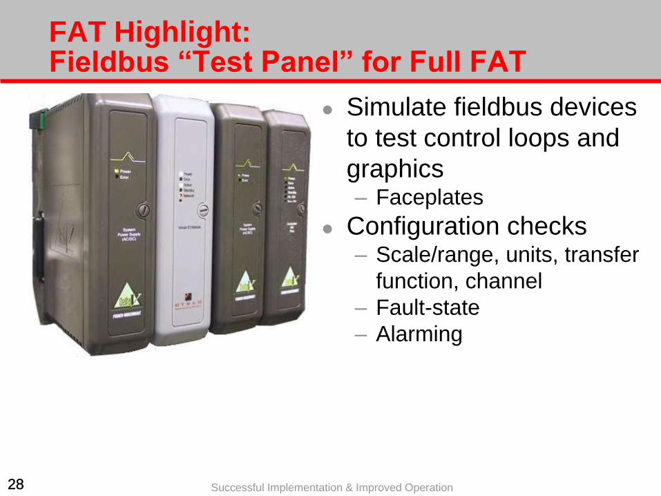
FAT Highlight: Fieldbus “Test Panel” for Full FAT
Simulate fieldbus devices
to test control loops and
graphics – Faceplates
Configuration checks – Scale/range, units, transfer
function, channel
– Fault-state
– Alarming

29 29 Successful Implementation & Improved Operation
FAT Highlight: Interoperability Testing
Test one of each device type
Ensures communication and DD file are OK
Test configuration download

30 30 Successful Implementation & Improved Operation
Installation / Construction
Laying the fieldbus cable and field
junction boxes

31 31 Successful Implementation & Improved Operation
Installation Highlight: Test Equipment
Establish procedure and checklist
Hands-on training for contractor
Required test tools are made available in
required quantity so as to not delay project – Fieldbus power and signal simulator
– Fieldbus tester
– Oscilloscope or ADM
– R and C meter

32 32 Successful Implementation & Improved Operation
Device Commissioning
Connecting the Fieldbus Devices

33 33 Successful Implementation & Improved Operation
Device Commissioning Highlight: Digital Way – Not Analog Way
Transmitters are not calibrated (trim) at site – Transmitters are calibrated (trim) in the factory
– Zeroing for mounting position done as usual
– Level transmitters scaled to percentage as usual
There is no five point 0-25-50-75-100 % test – (i.e. no 4-8-12-16-20 mA signal)
If range has to be changed, it is only done from
DCS, in a single place – From DCS it is downloaded to the transmitter

34 34 Successful Implementation & Improved Operation
Device Commissioning Highlight: Test Equipment
Establish procedure and checklist
Hands-on training for contractor
Required test tools are made available in
required quantity so as to not delay project – Fieldbus tester
– Oscilloscope or ADM
– Handheld field communicator

35 35 Successful Implementation & Improved Operation
Use Auto-Commissioning
Purchase devices pre-
tagged
Just connect the device to
the bus
Fully automatic
commissioning without
touching the DCS software – Automatic address
assignment
– Automatic configuration
download Order devices
with tag pre-
assigned

36 36 Successful Implementation & Improved Operation
Use of Express and Batch Download
If loops are not running, use express download – Utilizes full bandwidth
Use batch download – Multiple ports downloaded unattended

37 37 Successful Implementation & Improved Operation
Operational: Test Equipment
What test tools will be available on site for daily
troubleshooting after project team is disbanded? – Fieldbus tester
– Oscilloscope or ADM
– Handheld field communicator
– Fieldbus calibrator

38 38 Successful Implementation & Improved Operation
Summary
Evaluate system and
device ease of use
Task-oriented training
Specialized tools
Digital procedures, not
analog
Maximize FF use
Fieldbus experience
MIV lead
FDS
Pre-tag devices
Device interoperability
certification
Maximize CIF
Fast devices with broad
block library
Engineer Field
Diagnostics
FAT test plan
Manage DD files
Full FAT with
interoperability test
Installation &
commissioning
procedures and check
lists
Auto-commissioning
Express and batch
download