Embed Size (px)
Citation preview

Carnegie Mellon
1
Design of Digital Circuits 2017Srdjan CapkunOnur Mutlu(Guest starring: Frank K. Gürkaynak and Aanjhan Ranganathan)
Adapted from Digital Design and Computer Architecture, David Money Harris & Sarah L. Harris ©2007 Elsevier
http://www.syssec.ethz.ch/education/Digitaltechnik_17
Timing and Verification

Carnegie Mellon
2
What will we learn
Timing in Combinational circuits
▪ Propagation and Contamination Delays
Timing for Sequential circuits
▪ Setup and Hold time
▪ How fast can my circuit work?
How timing is modeled in Verilog
Verification using Verilog
▪ How can we make sure the circuit works correctly
▪ Designing Testbenches

Carnegie Mellon
3
The Goal Of Circuit Design Is To Optimize:
Area
▪ Net circuit area is proportional to the cost of the device
Speed / Throughput
▪ We want circuits that work faster, or do more
Power / Energy
▪ Mobile devices need to work with a limited power supply
▪ High performance devices dissipate more than 100W/cm2
Design Time
▪ Designers are expensive
▪ The competition will not wait for you

Carnegie Mellon
4
Requirements Depend On Application

Carnegie Mellon
5
Timing
Until now, we investigated mainly functionality
What determines how fast a circuit is andhow can we make faster circuits?
A
Y
Time
delay
A Y

Carnegie Mellon
6
Propagation and Contamination Delay
Propagation delay: tpd = max delay from input to output
Contamination delay: tcd = min delay from input to output
A
Y
Time
A Y
tpd
tcd

Carnegie Mellon
7
Propagation & Contamination Delay
Delay is caused by
▪ Capacitance and resistance in a circuit
▪ Speed of light limitation (not as fast as you think!)
Reasons why tpd and tcd may be different:
▪ Different rising and falling delays
▪ Multiple inputs and outputs, some of which are faster than others
▪ Circuits slow down when hot and speed up when cold

Carnegie Mellon
8
Critical (Long) and Short Paths
Critical (Long) Path: tpd = 2 tpd_AND + tpd_OR
Short Path: tcd = tcd_AND
AB
C
D Y
Critical Path
Short Path
n1
n2

Carnegie Mellon
9
Propagation times

Carnegie Mellon
10
Propagation times

Carnegie Mellon
11
Sequential Timing
Flip-flop samples D at clock edge
D must be stable when it is sampled
Similar to a photograph, D must be stable around the clock edge
If D is changing when it is sampled, metastability can occur
▪ Recall that a flip-flop copies the input D to the output Q on the rising edge of the clock. This process is called sampling D on the clock edge. If D is stable at either 0 or 1 when the clock rises, this behavior is clearly defined. But what happens if D is changing at the same time the clock rises?
D Flip-Flop
Symbols
D Q
Q

Carnegie Mellon
12
Input Timing Constraints
Setup time: tsetup = time before the clock edge that data must be stable (i.e. not changing)
Hold time: thold = time after the clock edge that data must be stable
Aperture time: ta = time around clock edge that data must be stable (ta = tsetup + thold)
CLK
tsetup
D
thold
ta
Carnegie Mellon
13
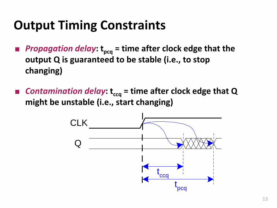
Output Timing Constraints
Propagation delay: tpcq = time after clock edge that the output Q is guaranteed to be stable (i.e., to stop changing)
Contamination delay: tccq = time after clock edge that Q might be unstable (i.e., start changing)
CLK
tccq
tpcq
Q

Carnegie Mellon
14
Dynamic Discipline
The input to a synchronous sequential circuit must be stable during the aperture (setup and hold) time around the clock edge.
Specifically, the input must be stable
▪ at least tsetup before the clock edge
▪ at least until thold after the clock edge

Carnegie Mellon
15
Dynamic Discipline
The delay between registers has a minimum and maximum delay, dependent on the delays of the circuit elements
CL
CLKCLK
R1 R2
Q1 D2
(a)
CLK
Q1
D2
(b)
Tc

Carnegie Mellon
16
Setup Time Constraint
The clock period or cycle time, Tc, is the time between rising edges of a repetitive clock signal. Its reciprocal, fc=1/Tc, is the clock frequency.
All else being the same, increasing the clock frequency increases the work that a digital system can accomplish per unit time.
Frequency is measured in units of Hertz (Hz), or cycles per second:
▪ 1 megahertz (MHz) 106 Hz
▪ 1 gigahertz (GHz) 109 Hz.

Carnegie Mellon
17
Setup Time Constraint
The setup time constraint depends on the maximum delay from register R1 through the combinational logic.
The input to register R2 must be stable at least tsetup before the clock edge.
CLK
Q1
D2
Tc
tpcq
tpd
tsetup
CL
CLKCLK
Q1 D2
R1 R2
Tc >=

Carnegie Mellon
18
Setup Time Constraint
The setup time constraint depends on the maximum delay from register R1 through the combinational logic.
The input to register R2 must be stable at least tsetup before the clock edge.
CLK
Q1
D2
Tc
tpcq
tpd
tsetup
CL
CLKCLK
Q1 D2
R1 R2
Tc >= tpcq + tpd + tsetup
tpd <=

Carnegie Mellon
19
Setup Time Constraint
The setup time constraint depends on the maximum delay from register R1 through the combinational logic.
The input to register R2 must be stable at least tsetup before the clock edge.
CLK
Q1
D2
Tc
tpcq
tpd
tsetup
CL
CLKCLK
Q1 D2
R1 R2
Tc >= tpcq + tpd + tsetup
tpd <= Tc – (tpcq + tsetup)

Carnegie Mellon
20
Hold Time Constraint
The hold time constraint depends on the minimum delay from register R1 through the combinational logic.
The input to register R2 must be stable for at least thold after the clock edge.
CLK
Q1
D2
tccq
tcd
thold
CL
CLKCLK
Q1 D2
R1 R2
thold <

Carnegie Mellon
21
Hold Time Constraint
The hold time constraint depends on the minimum delay from register R1 through the combinational logic.
The input to register R2 must be stable for at least thold after the clock edge.
CLK
Q1
D2
tccq
tcd
thold
CL
CLKCLK
Q1 D2
R1 R2
thold < tccq + tcd
tcd >

Carnegie Mellon
22
Hold Time Constraint
The hold time constraint depends on the minimum delay from register R1 through the combinational logic.
The input to register R2 must be stable for at least thold after the clock edge.
CLK
Q1
D2
tccq
tcd
thold
CL
CLKCLK
Q1 D2
R1 R2
thold < tccq + tcd
tcd > thold - tccq

Carnegie Mellon
23
Timing AnalysisCLK CLK
A
B
C
D
X'
Y'
X
Y
per
gate
Timing Characteristics
tccq = 30 ps
tpcq = 50 ps
tsetup = 60 ps
thold = 70 ps
tpd = 35 ps
tcd = 25 pstpd =
tcd =
Setup time constraint:
Tc ≥
fc = 1/Tc =
Hold time constraint:
tccq + tcd > thold ?

Carnegie Mellon
24
Timing AnalysisCLK CLK
A
B
C
D
X'
Y'
X
Y
tpd = 3 x 35 ps = 105 ps
tcd = 25 ps
Setup time constraint:
Tc ≥ (50 + 105 + 60) ps = 215 ps
fc = 1/Tc = 4.65 GHz
Hold time constraint:
tccq + tcd > thold ?
(30 + 25) ps > 70 ps ? No!p
er
gate
Timing Characteristics
tccq = 30 ps
tpcq = 50 ps
tsetup = 60 ps
thold = 70 ps
tpd = 35 ps
tcd = 25 ps

Carnegie Mellon
25
Fixing Hold Time Violation
CLK CLK
A
B
C
D
X'
Y'
X
Y
tpd =
tcd =
Setup time constraint:
Tc ≥
fc =
Hold time constraint:
tccq + tcd > thold ?
Add buffers to the short paths:
per
gate
Timing Characteristics
tccq = 30 ps
tpcq = 50 ps
tsetup = 60 ps
thold = 70 ps
tpd = 35 ps
tcd = 25 ps

Carnegie Mellon
26
Fixing Hold Time Violation
CLK CLK
A
B
C
D
X'
Y'
X
Y
tpd = 3 x 35 ps = 105 ps
tcd = 2 x 25 ps = 50 ps
Setup time constraint:
Tc ≥ (50 + 105 + 60) ps = 215 ps
fc = 1/Tc = 4.65 GHz
Hold time constraint:
tccq + tcd > thold ?
(30 + 50) ps > 70 ps ? Yes!
Add buffers to the short paths:
per
gate
Timing Characteristics
tccq = 30 ps
tpcq = 50 ps
tsetup = 60 ps
thold = 70 ps
tpd = 35 ps
tcd = 25 ps

Carnegie Mellon
27
Clock Skew
The clock doesn’t arrive at all registers at the same time
Skew is the difference between two clock edges
Examine the worst case to guarantee that the dynamic discipline is not violated for any register – many registers in a system!
tskew
CLK1
CLK2
CL
CLK2CLK1
R1 R2
Q1 D2
CLKdelay
CLK

Carnegie Mellon
28
Preikestolen - Norway6
00
m

Carnegie Mellon
29
Stay away from both HOLD and SETUP !
<- HOLDTIME
SETUP ->TIME
SAFE

Carnegie Mellon
30
How Do You Know That A Circuit Works?
You have written the Verilog code of a circuit
▪ Does it work correctly?
▪ Even if the syntax is correct, it might do what you want?
▪ What exactly it is that you want anyway?
Trial and error can be costly
▪ You need to ‘test’ your circuit in advance
In modern digital designs, functional verification is the most time consuming design stage.

Carnegie Mellon
31
The Idea Behind A Testbench
Using a computer simulator to test your circuit
▪ You instantiate your design
▪ Supply the circuit with some inputs
▪ See what it does
▪ Does it return the “correct” outputs?

Carnegie Mellon
32
Testbenches
HDL code written to test another HDL module, the device under test (dut), also called the unit under test (uut)
Not synthesizeable
Types of testbenches:
▪ Simple testbench
▪ Self-checking testbench
▪ Self-checking testbench with testvectors

Carnegie Mellon
33
Example
Write Verilog code to implement the following function in hardware:
y = (b ∙ c) + (a ∙ b)
Name the module sillyfunction

Carnegie Mellon
34
Example
module sillyfunction(input a, b, c,
output y);
assign y = ~b & ~c | a & ~b;
endmodule
Write Verilog code to implement the following function in hardware:
y = (b ∙ c) + (a ∙ b)
Name the module sillyfunction

Carnegie Mellon
35
Simple Testbench
module testbench1(); // Testbench has no inputs, outputsreg a, b, c; // Will be assigned in initial blockwire y;
// instantiate device under testsillyfunction dut (.a(a), .b(b), .c(c), .y(y) );d
// apply inputs one at a timeinitial begin // sequential blocka = 0; b = 0; c = 0; #10; // apply inputs, wait 10nsc = 1; #10; // apply inputs, wait 10nsb = 1; c = 0; #10; // etc .. etc..c = 1; #10;a = 1; b = 0; c = 0; #10;
endendmodule

Carnegie Mellon
36
Simple Testbench
Simple testbench instantiates the design under test
It applies a series of inputs
The outputs have to be observed and compared using a simulator program.
▪ This type of testbench does not help with the outputs
initial statement is similar to always, it just starts once at the beginning, and does not repeat.
The statements have to be blocking.

Carnegie Mellon
37
Self-checking Testbench
module testbench2();reg a, b, c;wire y;
// instantiate device under testsillyfunction dut(.a(a), .b(b), .c(c), .y(y));
// apply inputs one at a timeinitial begin
a = 0; b = 0; c = 0; #10; // apply input, waitif (y !== 1) $display("000 failed."); // checkc = 1; #10; // apply input, waitif (y !== 0) $display("001 failed."); // checkb = 1; c = 0; #10; // etc.. etc..if (y !== 0) $display("010 failed."); // check
endendmodule

Carnegie Mellon
38
Self-checking Testbench
Better than simple testbench
This testbench also includes a statement to check the current state
$display will write a message in the simulator
This is a lot of work
▪ Imagine a 32-bit processor executing a program (thousands of clock cycles)
You make the same amount of mistakes when writing testbenches as you do writing actual code

Carnegie Mellon
39
Testbench with Testvectors
The more elaborate testbench
Write testvector file: inputs and expected outputs
▪ Usually can use a high-level model (golden model) to produce the ‘correct’ input output vectors
Testbench:
▪ Generate clock for assigning inputs, reading outputs
▪ Read testvectors file into array
▪ Assign inputs, get expected outputs from DUT
▪ Compare outputs to expected outputs and report errors

Carnegie Mellon
40
Testbench with Testvectors
A testbench clock is used to synchronize I/O
▪ The same clock can be used for the DUT clock
Inputs are applied following a hold margin
Outputs are sampled before the next clock edge
▪ The example in book uses the falling clock edge to sample
Apply inputsafter some
delay from the clock
Check outputs before the next
clock edge
Clock period
HOLD MARGINSETUP
MARGIN

Carnegie Mellon
41
Testvectors File
We need to generate a testvector file (somehow)
File: example.tv – contains vectors of abc_yexpected000_1
001_0
010_0
011_0
100_1
101_1
110_0
111_0

Carnegie Mellon
42
Testbench: 1. Generate Clock
module testbench3();reg clk, reset; // clock and reset are internalreg a, b, c, yexpected; // values from testvectorswire y; // output of circuitreg [31:0] vectornum, errors; // bookkeeping variablesreg [3:0] testvectors[10000:0];// array of testvectors
// instantiate device under testsillyfunction dut(.a(a), .b(b), .c(c), .y(y) );
// generate clockalways // no sensitivity list, so it always executesbeginclk = 1; #5; clk = 0; #5; // 10ns period
end
Carnegie Mellon
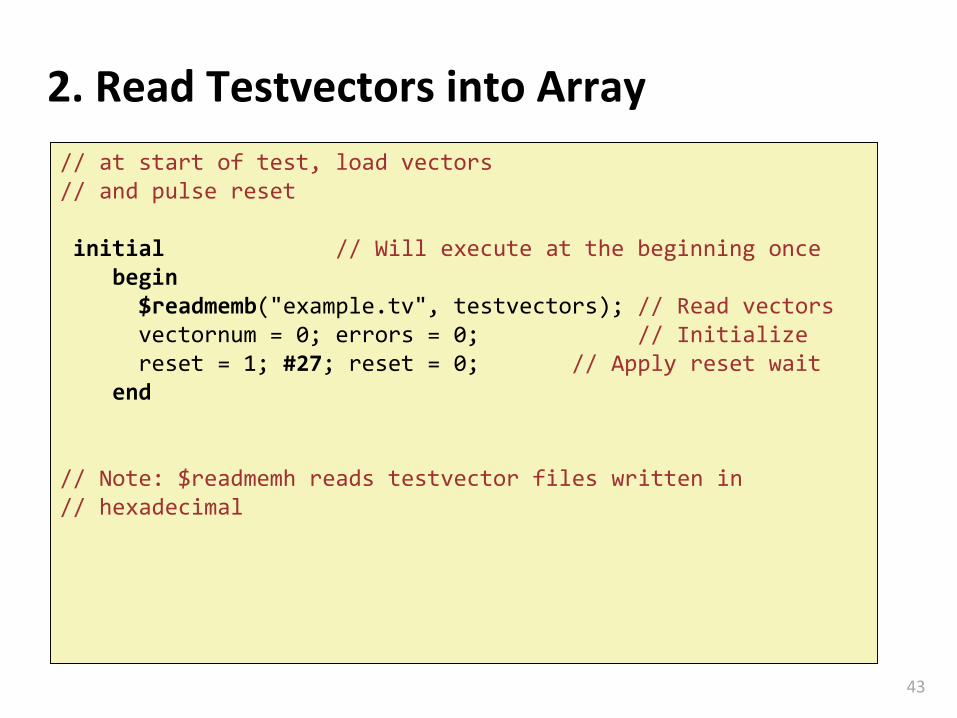
43
2. Read Testvectors into Array
// at start of test, load vectors// and pulse reset
initial // Will execute at the beginning oncebegin$readmemb("example.tv", testvectors); // Read vectorsvectornum = 0; errors = 0; // Initialize reset = 1; #27; reset = 0; // Apply reset wait
end
// Note: $readmemh reads testvector files written in// hexadecimal

Carnegie Mellon
44
3. Assign Inputs and Expected Outputs
// apply test vectors on rising edge of clkalways @(posedge clk)begin#1; {a, b, c, yexpected} = testvectors[vectornum];
end
Apply inputs with some delay (1ns) AFTER clock
This is important
▪ Inputs should not change at the same time with clock
Ideal circuits (HDL code) are immune, but real circuits (netlists) may suffer from hold violations.

Carnegie Mellon
45
4. Compare Outputs with Expected Outputs
// check results on falling edge of clkalways @(negedge clk)if (~reset) // skip during resetbeginif (y !== yexpected) begin
$display("Error: inputs = %b", {a, b, c});$display(" outputs = %b (%b exp)",y,yexpected);errors = errors + 1;
end// Note: to print in hexadecimal, use %h. For example,// $display(“Error: inputs = %h”, {a, b, c});

Carnegie Mellon
46
4. Compare Outputs with Expected Outputs
// increment array index and read next testvectorvectornum = vectornum + 1;if (testvectors[vectornum] === 4'bx)begin
$display("%d tests completed with %d errors", vectornum, errors);
$finish; // End simulation end
endendmodule
// Note: === and !== can compare values that are // x or z.

Carnegie Mellon
47
Golden Models
A golden model represents the ideal behavior of your circuit.
▪ Still it has to be developed
▪ It is difficult to get it right (bugs in the golden model!)
▪ Can be done in C, Perl, Python, Matlab or even in Verilog
The behavior of the circuit is compared against this golden model.
▪ Allows automated systems (very important)

Carnegie Mellon
48
Why is Verification difficult?
How long would it take to test a 32-bit adder?
▪ In such an adder there are 64 inputs = 264 possible inputs
▪ That makes around 1.85 1019 possibilities
▪ If you test one input in 1ns, you can test 109 inputs per second
▪ or 8.64 x 10¹⁴ inputs per day
▪ or 3.15 x 10¹⁷ inputs per year
▪ we would still need 58.5 years to test all possibilities
Brute force testing is not feasible for all circuits,we need alternatives
▪ Formal verification methods
▪ Choosing ‘critical cases’
▪ Not an easy task