Embed Size (px)
Citation preview
Applications & Tools
Answers for industry.
Timers on the Basis of a S7-1200 CPU in DTL Format SIMATIC S7-1200
Application Description August 2013

Warranty and Liability
Timers S7-1200 V1.0, Entry ID: 78788733 2
Cop
yrig
ht
Sie
men
s AG
201
3 Al
l rig
hts
rese
rved
Warranty and Liability
Note The Application Examples are not binding and do not claim to be complete regarding the circuits shown, equipping and any eventuality. The application examples do not represent customer-specific solutions. You are responsible for ensuring that the described products are used correctly. These Application Examples do not relieve you of your responsibility to use safe practices in application, installation, operation and maintenance. When using these application examples, you recognize that we cannot be made liable for any damage/claims beyond the liability clause described. We reserve the right to make changes to these Application Examples at any time and without prior notice. If there are any deviations between the recommendations provided in this application example and other Siemens publications – e.g. catalogs – the contents of the other documents have priority.
We do not accept any liability for the information contained in this document. Any claims against us – based on whatever legal reason – resulting from the use of the examples, information, programs, engineering and performance data etc., described in this application example will be excluded. Such an exclusion will not apply in the case of mandatory liability, e.g. under the German Product Liability Act (“Produkthaftungsgesetz”), in case of intent, gross negligence, or injury of life, body or health, guarantee for the quality of a product, fraudulent concealment of a deficiency or breach of a condition which goes to the root of the contract (“wesentliche Vertragspflichten”). The damages for a breach of a substantial contractual obligation are, however, limited to the foreseeable damage, typical for the type of contract, except in the event of intent or gross negligence or injury to life, body or health. The above provisions do not imply a change of the burden of proof to your detriment. Any form of duplication or distribution of these application examples or excerpts hereof is prohibited without the expressed consent of Siemens Industry Sector.
Siemens Industry Online Support This document is an article from the Siemens Industry Online Support. The following link takes you directly to the download page of this document: http://support.automation.siemens.com/WW/view/en/78788733
Table of Contents
Timers S7-1200 V1.0, Entry ID: 78788733 3
Cop
yrig
ht
Sie
men
s AG
201
3 Al
l rig
hts
rese
rved
Table of Contents Warranty and Liability ................................................................................................. 2 1 Task ..................................................................................................................... 5
1.1 Overview............................................................................................... 5 1.2 Requirements ....................................................................................... 5
2 Solution............................................................................................................... 6 2.1 Overview............................................................................................... 6 2.2 Description of the core functionality ..................................................... 6 2.3 Hardware and software components ................................................... 7 2.3.1 Validity .................................................................................................. 7 2.3.2 Components used ................................................................................ 7
3 Basics on the “DTL” format ............................................................................. 7 4 Mode of Operation ............................................................................................. 8
4.1 General overview ................................................................................. 8 Absolute time switching functions (chap. 4.3) ....................................... 8 Relative time switching functions and addition (chap. 4.4) ................... 8 Additional functions (chapter 4.5) ......................................................... 8
4.2 Program structure ................................................................................. 8 4.3 Absolute time switching functions ...................................................... 11 4.3.1 Day timer ............................................................................................ 11
Block name ......................................................................................... 11 Description ......................................................................................... 11 Function ............................................................................................ 11 Interfaces ............................................................................................ 11
4.3.2 Week timer ......................................................................................... 12 Block name ......................................................................................... 12 Description ......................................................................................... 12 Function ............................................................................................ 13 Interfaces ............................................................................................ 14
4.3.3 Month timer ........................................................................................ 15 Block name ......................................................................................... 15 Description ......................................................................................... 15 Function ............................................................................................ 15 Interfaces ............................................................................................ 16
4.3.4 Year timer ........................................................................................... 16 Block name ......................................................................................... 16 Description ......................................................................................... 16 Function ............................................................................................ 17 Interfaces ............................................................................................ 17
4.4 Relative timer and time switching functions ....................................... 18 4.4.1 Relative timer ..................................................................................... 18
Block name ......................................................................................... 18 Description ......................................................................................... 18 Function ............................................................................................ 18 Interfaces ............................................................................................ 19 Signal diagrams .................................................................................. 19
4.4.2 Addition in DTL format ........................................................................ 20 Block name ......................................................................................... 20 Description ......................................................................................... 20 Function ............................................................................................ 20 Interfaces ............................................................................................ 20

Table of Contents
Timers S7-1200 V1.0, Entry ID: 78788733 4
Cop
yrig
ht
Sie
men
s AG
201
3 Al
l rig
hts
rese
rved
4.5 Additional functions ............................................................................ 21 4.5.1 Automatic summer time/winter time changeover ............................... 21
Block name ......................................................................................... 21 Description ......................................................................................... 21 Function ............................................................................................ 21 Interfaces ............................................................................................ 21
4.5.2 Connection of radio clock module with DCF77 signal ........................ 22 Block name ......................................................................................... 22 Description ......................................................................................... 22 Function ............................................................................................ 22 Interfaces ............................................................................................ 23
5 Installation ........................................................................................................ 24 5.1 Hardware installation .......................................................................... 24 5.2 Installation of the software (download) ............................................... 24 5.3 Commissioning ................................................................................... 24
6 Operating the Application ............................................................................... 25 6.1 Absolute time switching functions ...................................................... 25
Month timer ........................................................................................ 25 6.2 Relative time switching functions ....................................................... 27
Relative timer ..................................................................................... 27 Addition in DTL format ........................................................................ 28
6.3 Additional functions (chapter 4.5) ....................................................... 29 Automatic summer time/winter time changeover ............................... 29 Connection of radio clock module with DCF77 signal ........................ 29
7 Further Notes, Tips & Tricks, etc. .................................................................. 30 How can you program several switch-on/switch-off times of the same
type? ................................................................................... 30 8 Related Literature ............................................................................................ 31 9 History............................................................................................................... 31

1 Task
Timers S7-1200 V1.0, Entry ID: 78788733 5
Cop
yrig
ht
Sie
men
s AG
201
3 Al
l rig
hts
rese
rved
1 Task 1.1 Overview
Introduction Many fields of automation technology require accurate timing of processes. Accurate time switching of processes is also necessary in a large number of industrial applications in the field of automation technology. For such applications the following instructions are available in the TIA Portal for the S7-1200: • under “Basic instructions” > “Timer operation” e.g. on and off delays • under “Extended instructions” > “Date and time-of -day“ e.g. “Add times“ and
“Read time-of-day” However, these instructions are not sufficient for all applications; e.g. if two times have to be added in DTL format of if a switch-on delay is to be programmed in DTL format. Analogous to the time switching functions for S7-300/400 under entry ID 21669756, the respective time switching functions for S7-1200 are included in this application.
1.2 Requirements
Range of functions To be able to design the above mentioned process sequences in terms of time, the S7-1200 requires time switching functions that, depending on the absolute time, set an output or which trigger a configured switching period based a specific event. The absolute start and end times for these processes have to be configurable at the respective function block in the “DTL” format. The switching distance between the start time and the end time has to be at least one second. All time interfaces of these function blocks are to be configured in the “DTL” format. The following time functions are included in this application: • Day timer • Week timer • Month timer • Year timer • Relative timer • Addition of two tags in DTL format • Automatic summer time/winter time changeover • Connecting a radio clock
2 Solution
Timers S7-1200 V1.0, Entry ID: 78788733 6
Cop
yrig
ht
Sie
men
s AG
201
3 Al
l rig
hts
rese
rved
2 Solution 2.1 Overview
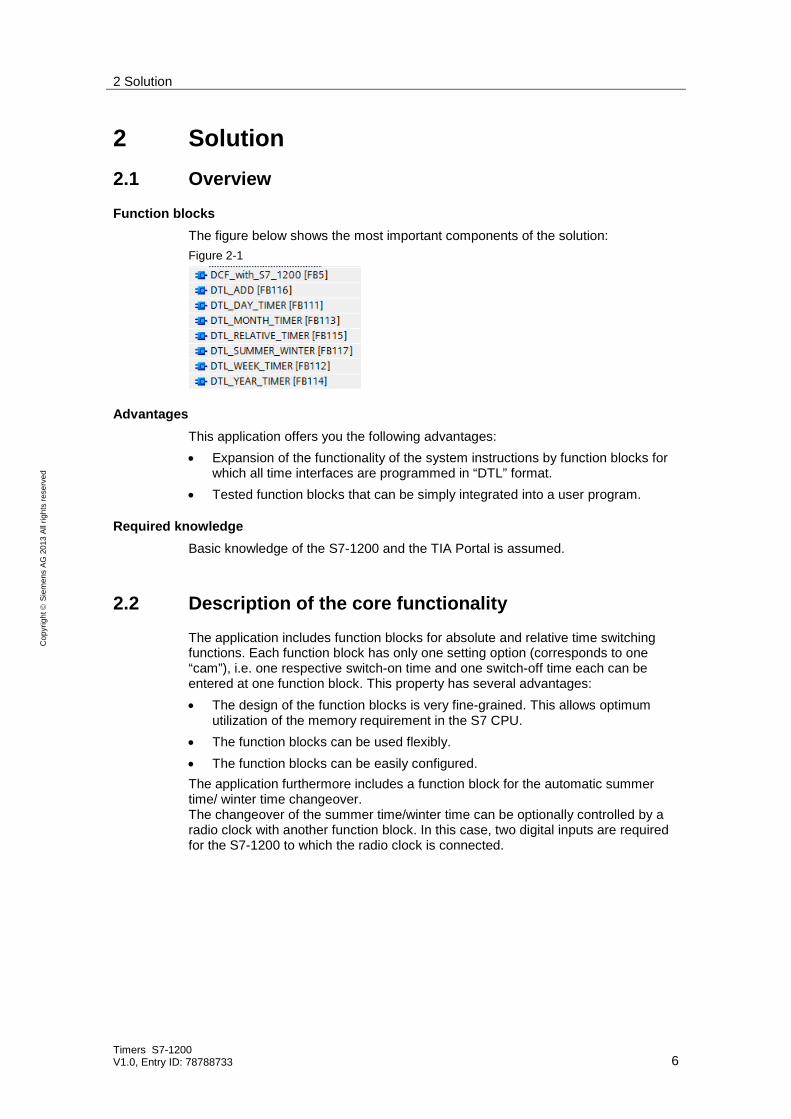
Function blocks The figure below shows the most important components of the solution: Figure 2-1
Advantages This application offers you the following advantages: • Expansion of the functionality of the system instructions by function blocks for
which all time interfaces are programmed in “DTL” format. • Tested function blocks that can be simply integrated into a user program.
Required knowledge Basic knowledge of the S7-1200 and the TIA Portal is assumed.
2.2 Description of the core functionality
The application includes function blocks for absolute and relative time switching functions. Each function block has only one setting option (corresponds to one “cam”), i.e. one respective switch-on time and one switch-off time each can be entered at one function block. This property has several advantages: • The design of the function blocks is very fine-grained. This allows optimum
utilization of the memory requirement in the S7 CPU. • The function blocks can be used flexibly. • The function blocks can be easily configured. The application furthermore includes a function block for the automatic summer time/ winter time changeover. The changeover of the summer time/winter time can be optionally controlled by a radio clock with another function block. In this case, two digital inputs are required for the S7-1200 to which the radio clock is connected.
3 Basics on the “DTL” format
Timers S7-1200 V1.0, Entry ID: 78788733 7
Cop
yrig
ht
Sie
men
s AG
201
3 Al
l rig
hts
rese
rved
2.3 Hardware and software components
2.3.1 Validity
This application is valid for • STEP 7 from V12 • S7-1200
2.3.2 Components used
The application was set up with the following components:
Hardware components Table 2-1
Component No. Order number Note
SIMATIC S7-1200 1 6ES7212-1AD30-0XB0 SIPLUS DCF77 TIME RECEIVER
1 6AG1057-1AA03-0AA0 Alternatively SICLOCK DCF77 (2XV9450-1AR36) can also be used.
Software components Table 2-2
Component No. Order number Note
STEP 7 Basic V12 SP1 1 6ES78220A.02-.. or STEP 7 PROF V12 SP1 1 6ES7822-1AA02-2YP4
Sample files and projects The following list includes all files and projects that are used in this example. Table 2-3
Component Note
78788733_S7-1200_DTL_Timer.zip This zip file contains the STEP 7 project
78788733_S7-1200_DTL_Timer.zip This document.
3 Basics on the “DTL” format Detailed information on the “DTL” format can be found in STEP7 (TIA Portal) in the “help” menu under the search term “DTL (S7-1200)”.

4 Mode of Operation
Timers S7-1200 V1.0, Entry ID: 78788733 8
Cop
yrig
ht
Sie
men
s AG
201
3 Al
l rig
hts
rese
rved
4 Mode of Operation 4.1 General overview
The functions included in this application are divided into three groups.
Absolute time switching functions (chap. 4.3) • Day timer • Week timer • Month timer • Year timer
Relative time switching functions and addition (chap. 4.4)
• Relative timer • Addition in DTL format
Additional functions (chapter 4.5)
• Automatic summer time/winter time changeover • Connection of radio clock module with DCF77 signal
4.2 Program structure
In the user program only the required functions have to be programmed. Absolute and relative time switching functions can also be called several times. In the user program the function blocks introduced here, do not necessarily have to be supplied via data blocks. The following program structure corresponds to the program of this application. Two programs which both trigger a summer time / winter time changeover must not be used in one program. This is why the “DCF_with_S7_1200” block is disabled via the “EN” parameter in this application. The system functions marked by * in the following figures are used for testing the manual changing of the system time and are not required in the user program. Further notes on setting the system time can be found in the “STEP 7 Professional V12.0” system manual under the term “System Time”. The function blocks have to be programmed according to their time critical processing: • To be able to receive switching times of the timers which are as precise as
possible, these function blocks have to be edited in the cyclic interrupt (OB 30). This includes the absolute time switching functions and the relative timer. The precision of the time switching function depends on a respectively short call interval of the cyclic interrupt.
• Non-time critical functions should be edited in the cyclic program (OB 1). This includes the addition in DTL format and the additional functions.

4 Mode of Operation
Timers S7-1200 V1.0, Entry ID: 78788733 9
Cop
yrig
ht
Sie
men
s AG
201
3 Al
l rig
hts
rese
rved
Figure 4-1: Program structure in cyclic interrupt
•
Cyclic Interrupt [OB30] WR_SYS_T
*
DB_DAY_DTL DB 111
DTL_DAY_TIMER _DB Instance DB 11 DTL_DAY_TIMER [FB 111]
CHECK_DTL_LIM [FC110]
WR_SYS_T
*
DB_WEEK_DTL Global DB 112
DTL_WEEK_TIMER _DB Instance DB 12
DTL_WEEK_TIMER [FB 112]
CHECK_DTL_LIM [FC110]
WR_SYS_T
*
DB_MONTH_DTL Global DB 113
DTL_MONTH_TIMER _DB Instance DB 13
DTL_MONTH_TIMER [FB 113]
CHECK_DTL_LIM [FC110]
WR_SYS_T
*
DB_YEAR_DTL Global DB 114
DTL_YEAR_TIMER _DB Instance DB 14
DTL_YEAR_TIMER [FB 114]
CHECK_DTL_LIM [FC110]

4 Mode of Operation
Timers S7-1200 V1.0, Entry ID: 78788733 10
Cop
yrig
ht
Sie
men
s AG
201
3 Al
l rig
hts
rese
rved
Figure 4-2: Program structure in cyclic program
Main [OB1]
DB_ ADD_DTL Global DB 116
DTL_ADD_DB Instance DB 16
DB_SUMMER_WINTER Global DB 117
DTL_SUMMER_ WINTER_DB
Instance DB 17
DCF_with_S7_1200_DB Instance DB 5
DB_DCF_DTL Global DB 125
WR_SYS_T
*
DB_RELATIVE_DTL Global DB 115
DTL_ RELATIVE_TIMER _DB Instance DB 15
DTL_REL_TIMER [FB 115]
CHECK_DTL_REL [FC115]
DTL_ADD [FB 116]
CHECK_DTL_ADD [FC116]
WR_SYS_T
*
DTL_SUMMER/WINTER [FB 117]
DCF_with_S7_1200 [FB5]

4 Mode of Operation
Timers S7-1200 V1.0, Entry ID: 78788733 11
Cop
yrig
ht
Sie
men
s AG
201
3 Al
l rig
hts
rese
rved
4.3 Absolute time switching functions
4.3.1 Day timer
Block name DTL_DAY_TIMER [FB111]
Description This block acquires a period of 24 hours. The maximum switching period is 23 hours, 59 minutes and 59 seconds. The switching times are repeated daily. For example, 8 am to 12 am Table 4-1: Period of the 24 hours DTL_DAY_TIMER function block 0 am 8 am 12 am 0 am
Function This function block compares the current system time with the two inputs Start_Time and End_Time. YEAR, MONTH, DAY of Start_Time and End_Time are not relevant (in all the tables that follow, non-relevant parameters are marked gray). Each comparator creates a pulse for setting/resetting the Q output. Accordingly, a Q is set when the system time is between Start_Time and End_Time. RQ resets the “Q” output to “FALSE”. When exceeding the input limits or if there are calculating errors caused by system blocks, the value “1” is output at the Error output. A description of the error messages of the used system blocks can be found in their help. The switching distance between Start_Time and End_Time is checked for a value >= 1 second. If this value is below this value the Error output = 2. Both cases are checked: Start_Time before End_Time; End_Time before Start_Time.
Interfaces Table 4-2
Parameter Declaration Data type Value range Description
Start_Time Input DTL 1970-01-01-00:00:00.0 2262-01-01-00:00:00.0
Start time
End_Time Input DTL 1970-01-01-00:00:00.0 2262-01-01-00:00:00.0
End time
RQ Input Bool TRUE FALSE
Resets the “Q” output to “FALSE”.
Q Output Bool TRUE FALSE
Timer active
Error Output Int 0000 0FFF
Error: 0001H: Configuration fault, Calculation error 0002H: Switching distance < 1 second
Int_Time Output DTL 1970-01-01-00:00:00.0 2262-01-01-00:00:00.0
System time

4 Mode of Operation
Timers S7-1200 V1.0, Entry ID: 78788733 12
Cop
yrig
ht
Sie
men
s AG
201
3 Al
l rig
hts
rese
rved
Table 4-3
Subprograms Description
CHECK_DTL_LIM [FC 110] Checks the parameters Start_Time and End_Time for reliable values
4.3.2 Week timer
Block name DTL_WEEK_TIMER [FB112]
Description This function block has three modes: • Period 7 days Maximum acquired period 7 days. The switching period is a maximum of 6 days, 23 hours, 59 minutes and 59 seconds. These switching times are repeated on a weekly basis. For example, every Tuesday from 8 pm to Friday 6 am. Table 4-4: Period of the 7 day DTL_WEEK_TIMER function block,
WEEKDAY = 1 …7
Sunday Tuesday Friday Saturday
• Period Monday – Friday Maximum acquired period 7 days. The maximum switching period is 23 hours, 59 minutes and 59 seconds. These switching times are repeated daily between Monday and Friday. For example from 8 pm to 6 am. Table 4-5: Period of the 7 day DTL_WEEK_TIMER function block,
WEEKDAY = 8 Monday Tuesday Friday Saturday

4 Mode of Operation
Timers S7-1200 V1.0, Entry ID: 78788733 13
Cop
yrig
ht
Sie
men
s AG
201
3 Al
l rig
hts
rese
rved
• Period Saturday and Sunday Maximum acquired period 7 days. The maximum switching period is 23 hours, 59 minutes and 59 seconds. These switching times are repeated daily Saturdays and Sundays. For example from 8 pm to 6 am. Table 4-6: Period of the 7 day DTL_WEEK_TIMER function block,
WEEKDAY = 9
Sunday Monday Saturday
Function This function block compares the current system time with the two inputs Start_Time and End_Time. YEAR, MONTH, DAY of Start_Time and End_Time are not relevant. Each comparator creates a pulse for setting/resetting the Q output. Accordingly, a Q is set when the system time is between Start_Time and End_Time. The mode of this function block is specified with the “WEEKDAY” DTL parameter included in Start_Time and End_Time: WEEKDAY = 1 ... 7: Sunday … Saturday. BOTH tags Start_Time and End_Time have to be located in a range of 1 ... 7. Start and end take place on the specified WEEKDAY. For example, Start_Time.WEEKDAY = 7, Start_Time.HOUR = 11, MINUTE = 10
End_Time.WEEKDAY = 3, End_Time.HOUR = 7, MINUTE = 5 The timer starts on Saturday, 11:10:00; the timer ends on Tuesday 07:05:00.
WEEKDAY = 8: all days between Mondays and Fridays BOTH tags Start_Time and End_Time have to be “8”. The time switching function starts every day between Monday and Friday, the time switching function ends every day between Monday and Friday. In case that the end time is before the start time, the time switching function will also end on Saturday For example, Start_Time.WEEKDAY = 8, Start_Time.HOUR = 3, MINUTE = 10
End_Time.WEEKDAY = 8, End_Time.HOUR = 16, MINUTE = 5 The timer starts each day between Monday and Friday at 3:10:00; the timer ends each day between Monday and on Friday at 16:05:00.
For example, Start_Time.WEEKDAY = 8, Start_Time.HOUR = 22, MINUTE = 10 End_Time.WEEKDAY = 8, End_Time.HOUR = 4, MINUTE = 5 The timer starts each day between Monday and Friday at 22:10:00; the timer ends each day between Tuesday and Saturday, 4:05:00.

4 Mode of Operation
Timers S7-1200 V1.0, Entry ID: 78788733 14
Cop
yrig
ht
Sie
men
s AG
201
3 Al
l rig
hts
rese
rved
WEEKDAY = 9: Saturday and Sunday BOTH tags Start_Time and End_Time have to be 9. The time switching function starts Saturday and Sunday, the time switching function ends Saturday and Sunday, In case that the end time is before the start time, the time switching function will also end on Monday For example, Start_Time.WEEKDAY = 9, Start_Time.HOUR = 3, MINUTE = 10
End_Time.WEEKDAY = 9, End_Time.HOUR = 16, MINUTE = 5 The timer starts on Saturday and Sunday, 03:10:00; the timer ends on Saturday and Sunday, 16:05:00.
For example, Start_Time.WEEKDAY = 9, Start_Time.HOUR = 22, MINUTE = 10 End_Time.WEEKDAY = 9, End_Time.HOUR = 4, MINUTE = 5 The timer starts on Saturday and Sunday at 22:10:00; the timer ends on Sunday and Monday at 4:05:00.
General: RQ resets the “Q” output to “FALSE”. When exceeding the input limits or if there are calculating errors caused by system blocks, the value “1” is output at the Error output. A description of the error messages of the system blocks used can be found in their help. The switching distance between Start_Time and End_Time is checked for a value >= 1 second. If this value falls below, the Error output = 2. Both cases are checked: Start_Time before End_Time; End_Time before Start_Time.
Interfaces Table 4-7
Parameter Declaration Data type Value range Description
Start_Time Input DTL 1970-01-01-00:00:00.0 2262-01-01-00:00:00.0
Start time
Start_Time.WEEKDAY
Input DTL 1 9
Weekday of start time
End_Time Input DTL 1970-01-01-00:00:00.0 2262-01-01-00:00:00.0
End time
End_Time. WEEKDAY
Input DTL 1 9
Weekday of end time
RQ Input Bool TRUE FALSE
Resets the “Q” output to “FALSE”.
Q Output Bool TRUE FALSE
Timer active
Error Output Int 0000 H 0FFF H
Error: 0001 H: Configuration fault, Calculation error 0002 H: Switching distance < 1 second
Int_Time Output DTL 1970-01-01-00:00:00.0 2262-01-01-00:00:00.0
System time
Table 4-8
Subprograms Description
CHECK_DTL_LIM [FC 110] Checks the parameters Start_Time and End_Time for reliable values

4 Mode of Operation
Timers S7-1200 V1.0, Entry ID: 78788733 15
Cop
yrig
ht
Sie
men
s AG
201
3 Al
l rig
hts
rese
rved
4.3.3 Month timer
Block name DTL_MONTH_TIMER [FB113]
Description This block acquires a period of a maximum of 31 days. The switching period is a maximum of 30 days, 23 hours, 59 minutes and 59 seconds, e.g. each month from the 3rd, 12 am to the 7th, 0 am. Considered are also special cases where the start date is on the last day of the month and the following month has fewer days. In this case and for a maximum switching period, the day of the end time is calculated for the last day of the following month. The calculation of the end time is the same as for all other start days. Table 4-9: Period of the 1 month DTL_MONTH_TIMER function block
Jan Feb. March Apr May Jun Jul Aug Sept Oct Nov Dec.
Function This function block compares the current system time with the two inputs Start_Time and End_Time. YEAR, MONTH, DAY of Start_Time and End_Time are not relevant. Each comparator creates a pulse for setting/resetting the Q output. Accordingly, a Q is set when the system time is between Start_Time and End_Time. RQ resets the “Q” output to “FALSE”. When exceeding the input limits or if there are calculating errors caused by system blocks, the value “1” is output at the output. A description of the error messages of the system blocks used can be found in their help. The switching distance between Start_Time and End_Time is checked for a value >= 1 second. If this value falls below, the Error output = 2. Both cases are checked: Start_Time before End_Time; End_Time before Start_Time.

4 Mode of Operation
Timers S7-1200 V1.0, Entry ID: 78788733 16
Cop
yrig
ht
Sie
men
s AG
201
3 Al
l rig
hts
rese
rved
Interfaces Table 4-10
Parameter Declaration Data type Value range Description
Start_Time Input DTL 1970-01-01-00:00:00.0 2262-01-01-00:00:00.0
Start time
End_Time Input DTL 1970-01-01-00:00:00.0 2262-01-01-00:00:00.0
End time
RQ Input Bool TRUE FALSE
Resets the “Q” output to “FALSE”.
Q Output Bool TRUE FALSE
Timer active
Error Output Int 0000 H 0FFF H
Error: 0001 H: Configuration fault, Calculation error 0002 H: Switching distance < 1 second
Int_Time Output DTL 1970-01-01-00:00:00.0 2262-01-01-00:00:00.0
System time
Table 4-11
Subprograms Description
CHECK_DTL_LIM [FC 110] Checks the parameters Start_Time and End_Time for reliable values
4.3.4 Year timer
Block name DTL_YEAR_TIMER [FB114]
Description This block acquires a period of 365 / 366 days. The switching period is a maximum of 11 months, 30 days, 23 hours, 59 minutes and 59 seconds, e.g. from 11th April, 0 am to 21st September, 0 am. Special cases where the start date is on the last day of the month and the following month has fewer days or where the start date falls on the 29th February of a leap year are also considered. In these cases and for a maximum switching period, the day of the end time is calculated for the last day of the following month. The calculation of the end time is the same as for all other start days. Table 4-12: Period of the 1 year DTL_YEAR_TIMER function block
2013 2014 … Jan
Feb.
March
Apr
May
Jun
Jul
Aug
Sept
Oct
Nov
Dec.

4 Mode of Operation
Timers S7-1200 V1.0, Entry ID: 78788733 17
Cop
yrig
ht
Sie
men
s AG
201
3 Al
l rig
hts
rese
rved
Function This function block compares the current system time with the two inputs Start_Time and End_Time. YEAR of Start_Time and End_Time is not relevant. Each comparator creates a pulse for setting/resetting the Q output. Accordingly, a Q is set when the system time is between Start_Time and End_Time. RQ resets the “Q” output to “FALSE”. When exceeding the input limits or if there are calculating errors caused by system blocks, the value “1” is output at the Error output. A description of the error messages of the system blocks used can be found in their help. The switching distance between Start_Time and End_Time is checked for a value >= 1 second. If this value falls below, the Error output = 2. Both cases are checked: Start_Time before End_Time; End_Time before Start_Time.
Interfaces Table 4-13
Parameter Declaration Data type Value range Description
Start_Time Input DTL 1970-01-01-00:00:00.0 2262-01-01-00:00:00.0
Start time
End_Time Input DTL 1970-01-01-00:00:00.0 2262-01-01-00:00:00.0
End time
RQ Input Bool TRUE FALSE
Resets the “Q” output to “FALSE”.
Q Output Bool TRUE FALSE
Timer active
Error Output Int 0000 H 0FFF H
Error: 0001 H: Configuration fault, Calculation error 0002 H: Switching distance < 1 second
Int_Time Output DTL 1970-01-01-00:00:00.0 2262-01-01-00:00:00.0
System time
Table 4-14
Subprograms Description
CHECK_DTL_LIM [FC 110] Checks the parameters Start_Time and End_Time for reliable values

4 Mode of Operation
Timers S7-1200 V1.0, Entry ID: 78788733 18
Cop
yrig
ht
Sie
men
s AG
201
3 Al
l rig
hts
rese
rved
4.4 Relative timer and time switching functions
4.4.1 Relative timer
Block name DTL_RELATIVE_TIMER [FB115]
Description With a start pulse the timer is enabled and remains active until the configured switching period has lapsed. Table 4-15: Switching period of the DTL_REL_TIMER function block maximum 200 years
Current time Relative time (switching
End time YEAR MONTH DAY HOUR MINUTE SEC. YEAR MONTH DAY HOUR MINUTE SEC. YEAR MONTH DAY HOUR MINUTE SEC.
Function This function block adds the switching time (Rel_Time) to the current time (Int_Time). The calculated end time of the timer is output at the End_Time output when it has been calculated and the timer is running. The end time is set to zero whilst it is calculated or has lapsed. The current system time is copied to the Int_Time output. The format of Int_Time, Rel_Time and End_Time is DTL. The Q output is set to “TRUE” straight away when the time switch is started by a pulse on the Start_Time input. When the Check_Edge input is “TRUE”, the timer restarts at every pulse on the Start_Time input. When the Check_Edge input is “FALSE” the timer can only be restarted when the End_time has been reached. The RQ input always resets the timer; the timer can then be restarted. When the input limits are exceeded the value “1” is output at the Error output. A calculation error triggered by the system blocks used results in a value on the Error output = 2. Descriptions on this matter can be found in the help of the system blocks used. Note: The End_Time range is limited to the year 2262.
4 Mode of Operation
Timers S7-1200 V1.0, Entry ID: 78788733 19
Cop
yrig
ht
Sie
men
s AG
201
3 Al
l rig
hts
rese
rved
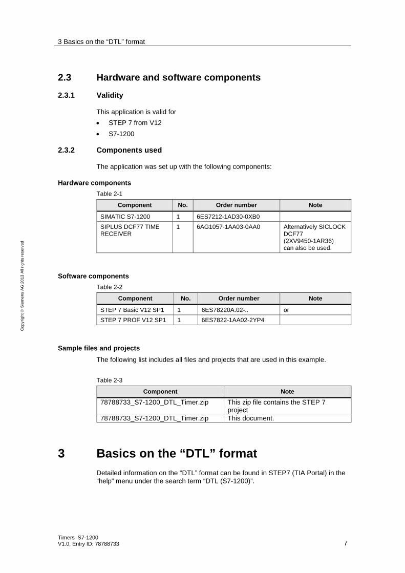
Interfaces Table 4-16
Parameter Declaration Data type Value range Description
Check_Edge Input Bool TRUE FALSE
If “TRUE”: Restart at Start_Time
Start_Time Input Bool TRUE FALSE
Pulse for starting the timer and for calculating the end time
Rel_Time Input DTL 0-00-00-00:00:00.1 200-00-00-00:00:00.0
End time, maximum switching time 200 years, 11 months, 30 days, 23 hours, 59 minutes and 59 seconds
RQ Input Bool TRUE FALSE
Resets the “Q” output to “FALSE”.
Q Output Bool TRUE FALSE
Timer active
Error Output Int 0000 H 0FFF H
Error: 0001 H: Configuration error 0002 H: Calculation error
Int_Time Output DTL 1970-01-01-00:00:00.0 2262-01-01-00:00:00.0
System time
Table 4-17
Subprograms Description
CHECK_DTL_REL [FC 115] Checks the Rel_Time parameter for reliable values
Signal diagrams Table 4-18: Behavior for “Check_Edge” = “FALSE” signal
Signal
Check_Edge
Start_Time
RQ
Q
Table 4-19: Behavior for “Check_Edge” = “TRUE” signal Signal
Check_Edge
Start_Time
RQ
Q

4 Mode of Operation
Timers S7-1200 V1.0, Entry ID: 78788733 20
Cop
yrig
ht
Sie
men
s AG
201
3 Al
l rig
hts
rese
rved
4.4.2 Addition in DTL format
Block name DTL_ADD [FB116]
Description The function block adds two summands in DTL format. This format is defined from 1970. This is why the summand 1 has to at least correspond to this value. The summand 2 has to be in a range of 1 second up to a recommended value of 200 years. The sum must not continue to go beyond the year 2262. Table 4-20
Summand 1 Summand 2 Total YEAR MONTH DAY HOUR MINUTE SEC. YEAR MONTH DAY HOUR MINUTE SEC. YEAR MONTH DAY HOUR MINUTE SEC.
Function This function block calculates the sum of summand_1 and summand_2, if a change of edge from “TRUE” to Start_Calc is detected. The format of Summand_1, Summand_2 and the sum is DTL. When the calculation of the sum has been completed the output Calculated becomes “TRUE”. When the input limits are exceeded the value at the Error output = 1. A calculation error triggered by the system blocks used results in a value on the Error output = 2. Descriptions on this matter can be found in the help of the system blocks used.
Interfaces Table 4-21
Parameter Declaration Data type Value range Description
Start_Calc Input Bool TRUE FALSE
Pulse for start calculating of Sum
Summand_1 Input DTL 1970-01-01-00:00:00.0 2262-01-01-00:00:00.0
Base time corresponds to a time
Summand_2 Input DTL 0-00-00-00:00:00.1 200-00-00-00:00:00.0
Difference time corresponds to a period
Sum Output DTL 1970-01-01-00:00:00.0 2262-01-01-00:00:00.0
Calculated time corresponds a time
Calculated Output Bool TRUE FALSE
Calculation of sum completed
Error Output Int 0000 H 0FFF H
Error: 0001 H: Configuration error 0002 H: Calculation error
Table 4-22
Subprograms Description
check_DTL_LIM [FC 116] Checks Summand_1 and Summand_2 for reliable values

4 Mode of Operation
Timers S7-1200 V1.0, Entry ID: 78788733 21
Cop
yrig
ht
Sie
men
s AG
201
3 Al
l rig
hts
rese
rved
4.5 Additional functions
4.5.1 Automatic summer time/winter time changeover
Block name DTL_SUMMER_WINTER [FB117]
Description The adjustment to the system time is automatic with the officially fixed times.
Function This function block reads and writes the system time. Depending on the rules for the switchover between winter time and summer time, the system is automatically switched over. Whilst the summer time is active the summer output is set to “TRUE”. The Error output includes both RET_VALs of the system functions RD_SYS_T and WR_SYS_T. RD_SYS_T is assigned to the #stat_ret_val.W0 word and WR_SYS_T to the #stat_ret_val.W1 word. Descriptions on this matter can be found in the help of the system blocks used.
Interfaces Table 4-23
Parameter Declaration Data type Value range Description
Time Output DTL 1970-01-01-00:00:00.0 2262-01-01-00:00:00.0
Current time
Summer Output Bool TRUE FALSE
Summer time active
Error Output DInt 0000 0000 H 0FFF FFFF H
Error see help for “RD_SYS_T“ and “WR_SYS_T“
Table 4-24
Subprograms Description
none ---

4 Mode of Operation
Timers S7-1200 V1.0, Entry ID: 78788733 22
Cop
yrig
ht
Sie
men
s AG
201
3 Al
l rig
hts
rese
rved
4.5.2 Connection of radio clock module with DCF77 signal
Block name DCF_with_S7_1200 [FB5]
Description Figure 4-3: Configuration S7-1200 with SIPLUS DCF77
The function block includes the following functions: • Acquiring time signal of the radio clock module • Decoding time signal • Conversion of the data into the DTL format • Adjusting module time of the S7-1200 • Error detection in the signal • Supplying information on the current status
Function The SIPLUS radio clock module DCF77 supplies coded information on the current time and date. The DCF_with_S7_1200 function block decodes this information and overwrites the system time of the S7-1200.

4 Mode of Operation
Timers S7-1200 V1.0, Entry ID: 78788733 23
Cop
yrig
ht
Sie
men
s AG
201
3 Al
l rig
hts
rese
rved
Interfaces Table 4-25
Parameter Declaration Data type Value range Description
Timezone Input INT +12 -12
Specifying time zone in which the S7- 1200 is located, depending on the UTC/GMT. For example, in Germany = +1, since there is an hour time difference
DCF77_data Input BOOL FALSE TRUE
This is where the input is created which is wired with the DCF data signal of the radio clock module.
DCF77_tact Input BOOL FALSE TRUE
This is where the input is created which is wired with the sec cycle of the radio clock module.
Time Output DTL 1970-01-01-00:00:00.0 2262-01-01-00:00:00.0
Entry of the time received by the DCF77 with which the CPU is synchronized.
Sync Output BOOL FALSE TRUE
If this value is “TRUE”, the CPU time is the time of the DCF77 – time signal. The CPU is synchronous. This is only the case if there are no errors.
Summer time Output BOOL FALSE TRUE
Gives information on summer time “TRUE“ = summer time “FALSE“ = winter time
Error_Code Output WORD 0FFF H 0000 H
The error code gives information on several signal errors.
Table 4-26
Subprograms Description
none ---
A further documentation on this function block can be found under the following link: http://support.automation.siemens.com/WW/view/en/63628396
5 Installation
Timers S7-1200 V1.0, Entry ID: 78788733 24
Cop
yrig
ht
Sie
men
s AG
201
3 Al
l rig
hts
rese
rved
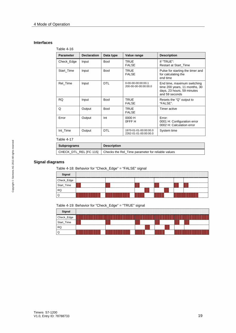
5 Installation In this chapter you can find the necessary steps in order to operate the code from the download and the hardware from the above list.
5.1 Hardware installation
A hardware installation is only required for the setup with the connection of the radio clock module with DCF77 signal. The description can be found under the following link: http://support.automation.siemens.com/WW/view/en/63628396
5.2 Installation of the software (download)
This chapter describes the steps for the installation of the example code. Table 5-1
No. Action Comments
1. Load the download 78788733_S7-1200_DTL_Timer.zip into a respective directory
2. Unzip the files into a respective directory 3. Start the TIA Portal 4. Open the global “78788733_S7-
1200_DTL_Timer” library via the menu: Tools > Global library > Open library… > 78788733_S7-1200_DTL_Timer > 78788733_S7-1200_DTL_Timer.al12
5. Create a new project 6. Add a new device From the group of the SIMATIC
S7-1200 CPU 7. Copy all blocks from the master copy of the
global “78788733_S7-1200_DTL_Timer” library, for example via drag and drop into the program block folder of the project
8. Copy the tag tables accordingly into the watch and force tables
5.3 Commissioning Table 5-2
No. Action Comments
1. Create a connection to the S7-1200. See S7-1200 automation system manual
6 Operating the Application
Timers S7-1200 V1.0, Entry ID: 78788733 25
Cop
yrig
ht
Sie
men
s AG
201
3 Al
l rig
hts
rese
rved
6 Operating the Application This application provides tag tables as an operating option for the time and special functions.
Note The individual input and output parameters of the functions have already been described in chapter 5 Describing the time switching functions.
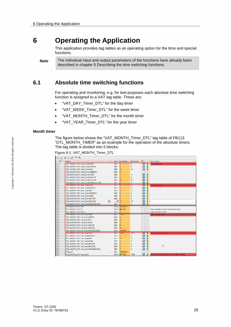
6.1 Absolute time switching functions For operating and monitoring, e.g. for test purposes each absolute time switching function is assigned to a VAT tag table. These are: • “VAT_DAY_Timer_DTL” for the day timer • “VAT_WEEK_Timer_DTL” for the week timer • “VAT_MONTH_Timer_DTL” for the month timer • “VAT_YEAR_Timer_DTL” for the year timer
Month timer The figure below shows the “VAT_MONTH_Timer_DTL” tag table of FB113 “DTL_MONTH_TIMER” as an example for the operation of the absolute timers. The tag table is divided into 5 blocks: Figure 6-1: VAT_MONTH_Timer_DTL

6 Operating the Application
Timers S7-1200 V1.0, Entry ID: 78788733 26
Cop
yrig
ht
Sie
men
s AG
201
3 Al
l rig
hts
rese
rved
• 1st and 2nd block: setting of start and end times of the timer • 3rd block: resetting of timer, output of timer, error information • 4th block: System time • 5th block: setting of system time. The transfer takes place during the change of
edge to “TRUE” on the DB_MONTH_DTL.set_pulse bit. Table 6-1
No. Action Comments
1. Call the respective watch table under “watch and force tables”
2. Set the system time via block 5 and execute a change of edge to “TRUE” at “DB_MONTH_DTL.set_pulse” so that the value is accepted. Use the tag button
“modify now“
The “WEEKDAY” parameters are only relevant for the week timer
3. Monitor the changed system time in block 4 4. Set the start and end time on block 1 and 2. 5. Monitor the error information when invalid values are
entered
6. Monitor the output of the timer when • the start time is reached • the end time is reached
7. Repeat steps 1 – 5 if required.

6 Operating the Application
Timers S7-1200 V1.0, Entry ID: 78788733 27
Cop
yrig
ht
Sie
men
s AG
201
3 Al
l rig
hts
rese
rved
6.2 Relative time switching functions
Relative timer The “VAT_REL_timer_DTL” tag table is available for operating and monitoring, e.g. to test the relative time switching function. The tag table is divided into 6 blocks: Figure 6-2: VAT_REL_Timer_DTL
• 1st block: Start the time switching function via
“DB_RELATIVE_DTL.check_Edge” and “DB_RELATIVE_DTL.start_time”, see 4.4.1
• 2nd und 3rd block: setting of relative and end time of the timer • 4th block: resetting of timer, output of timer, error information • 5th block: system time • 6th block: setting of system time. The transfer takes place during the change of
edge to “TRUE” on the DB_MONTH_DTL.set_pulse bit. Table 6-2
No. Action Comments
1. Call the respective watch table under “watch and force tables”
2. Set the system time via block 6 and execute a change of edge to “TRUE” at “DB_MONTH_DTL.set_pulse” so that the value is accepted. Use the tag button “modify
now“
3. Monitor the changed system time in block 5 4. Set the relative time on block 2. 5. Monitor the error information when invalid
values are entered

6 Operating the Application
Timers S7-1200 V1.0, Entry ID: 78788733 28
Cop
yrig
ht
Sie
men
s AG
201
3 Al
l rig
hts
rese
rved
No. Action Comments
6. Monitor the “DB_RELATIVE_DTL.Q“ output of the timer when
• the start time is set • the end time is reached
In this period the end time is calculated. In order to have only a low load on the cycle time, the calculation of, e.g. years can take some minutes, which in practice is not relevant.
7. Repeat steps 1 – 6 if required.
Addition in DTL format The “VAT_ADD_DTL” tag table is available for operating and monitoring, e.g. to test the addition in DTL format. The tag table is divided into 6 blocks: Figure 6-3: VAT_ADD_DTL
• 1st block: Start the addition with the change of edge to “TRUE” via
“DB_ADD_DTL.Start_Calc” • 2nd and 3rd block: setting of Summand_1 and Summand_2 • 4th block: calculation status bit sum completed • 5th block: total • 6th block: error information Table 6-3
No. Action Comments
1. Call the respective watch table under “watch and force tables”
2. Enter Summand_1 as time 3. Enter Summand_2 as period
(configuration see 4.4.2) 4. Execute a change of edge to “TRUE” to
“DB_ADD_DTL.Start_Calc” so that the values can be accepted. Use the tag button “modify
now“
5. Monitor the outputs “DB_ADD_DTL.Q” and “DB_ADD_DTL.Sum”
The calculation of longer periods, e.g. of years can take

6 Operating the Application
Timers S7-1200 V1.0, Entry ID: 78788733 29
Cop
yrig
ht
Sie
men
s AG
201
3 Al
l rig
hts
rese
rved
No. Action Comments some minutes
6. Monitor the error information when invalid values are entered
6.3 Additional functions (chapter 4.5)
Automatic summer time/winter time changeover The “VAT_SUMMER_WINTER” tag table is available for operating and monitoring, e.g. to test the automatic summer time/winter time changeover. The tag table is divided into 5 blocks: Figure 6-4: VAT_SUMMER_WINTER
• 1st setting of system time. The transfer takes place during the change of edge
to “TRUE” on the DB_SUMMER_WINTER.set_pulse bit. • 2nd block: setting of values of the system time • 3rd block: summer time status bit • 4th block: error information • 5th block: system time Table 6-4
No. Action Comments
1. Set the system time directly before the changeover to summer time
Further details can be found, e.g. in wikipedia.org
2. Observe how the time “jumps” from 02:00 to 03:00 when switching the DB_SUMMER_WINTER.Summer bit
3. Set the system time directly before the changeover to winter time
4. Observe how the time “jumps” from 03:00 to 02:00 when switching the DB_SUMMER_WINTER.Summer bit
This behavior does not occur a 2nd time when 03:00 is reached again
Connection of radio clock module with DCF77 signal This function is the subject of an independent entry. Further information on this function block is available at the following link: http://support.automation.siemens.com/WW/view/en/63628396

7 Further Notes, Tips & Tricks, etc.
Timers S7-1200 V1.0, Entry ID: 78788733 30
Cop
yrig
ht
Sie
men
s AG
201
3 Al
l rig
hts
rese
rved
7 Further Notes, Tips & Tricks, etc. How can you program several switch-on/switch-off times of the same type?
Table 7-1
No. Action Comments
1 Create a global data block for the desired function block, e.g. by copying when its interfaces are to be provided via DB.
Alternatively the global data block can be expanded according to its function block.
2 Search for the type of function block in the example program that you require a second time.
3 Add a new network under it. 4 Call the respective function block there and
supply it, if required, with the respective data blocks.
The function block can also be called with another structure. It is important that it is called, as shown here, via the cyclic interrupt or via cyclic editing.
5 Integrate the interfaces into your user program. 6 Compile the project. 7 Transfer the program into your S7-1200
8 Related Literature
Timers S7-1200 V1.0, Entry ID: 78788733 31
Cop
yrig
ht
Sie
men
s AG
201
3 Al
l rig
hts
rese
rved
8 Related Literature Table 8-1:
Topic Title
\1\ Siemens Industry Online Support
http://support.automation.siemens.com
\2\ Download page of the entry
http://support.automation.siemens.com/WW/view/en/78788733
\3\ S7-300/400 CPUs: Time switches on the basis of S7-300/400 CPUs, optional radio clock connection
http://support.automation.siemens.com/WW/view/en/21669756
\4\ Connection of radio clock module with DCF77 signal
http://support.automation.siemens.com/WW/view/en/63628396
\5\ S7-1200 System Manual
http://support.automation.siemens.com/WW/view/en/36932465
\6\ STEP 7 Professional V12.0 (TIA Portal)
http://support.automation.siemens.com/WW/view/en/68113685
9 History Table 9-1:
Version Date Modifications
V1.0 08/2013 First version