Embed Size (px)
Citation preview

Time Current Curves TD012033EN Effective April 2014
ContentsDescription Page
Catalog Number Selection . . . . . . . . . . . . . . . . . . . . . . . . . . . . . . . . . . . . . . . . . . . . . . . . . . . . . . . . . . . . . . . . . . . . .3
JT Thermal/Magnetic Trip Unit
JDB, JD, HJD 2, 3 and 4 Poles . . . . . . . . . . . . . . . . . . . . . . . . . . . . . . . . . . . . . . . . . . . . . . SC-4247-87D . . . . . . . . .4JDC 2, 3 and 4 Poles . . . . . . . . . . . . . . . . . . . . . . . . . . . . . . . . . . . . . . . . . . . . . . . . . . . . . SC-4248-87C . . . . . . . . .5
Let-Through CurvesJDC, FDC, KDC, and LDC---240V . . . . . . . . . . . . . . . . . . . . . . . . . . . . . . . . . . . . . . . . . . . . . AD-29-166A . . . . . . . . .6JDC, FDC, KDC, and LDC---480V . . . . . . . . . . . . . . . . . . . . . . . . . . . . . . . . . . . . . . . . . . . . . AD-29-166B . . . . . . . . .7JDC, FDC, KDC, and LDC---600V . . . . . . . . . . . . . . . . . . . . . . . . . . . . . . . . . . . . . . . . . . . . . AD-29-166C . . . . . . . . .8
Eaton Leakage Module CurvesUL Earth Leakage Curve ELFD, JD, and KD, three- and four-pole, 110-480V . . . . . . . . . . . TC01212005E . . . . . . . .9IEC Earth Leakage Curve ELFD, JD, and KD, three- and four-pole, 110-480V . . . . . . . . . . . TC01212006E . . . . . . .10
Note:Time/Current characteristic curves for Series C J-frame circuit breakers--voltages shown in curve headingsare maximum at which the breaker may be applied . Interrupting capacity of inidvidual breaker is tabulatedon each curve .
Note:The following curves are UL489 Listed for use in North America .The following circuit breakers are derived from Eaton, Westinghouse, or Cutler-Hammer history .
Time Current Curves are engineering reference documents for application and coordination purposes only. For field testing molded case circuit breakers, refer to NEMA AB 4 guidelines.
Series C J-Frame 70-250 amperes, 240-600 volts

2
Time Current Curves TD012033ENEffective April 2014
Series CJ-Frame
eaton www.eaton.com
otee:N Unless noted below, all curves remain unchanged from their prior revision .
Revision Curve Number Page Date

3
Time Current Curves TD012033ENEffective April 2014
Series CJ-Frame
eaton www.eaton.com
JD 3 250 F
Circuit Breaker/Frame Type
JDBJDHJDJDC
Number of Poles
234
= 2 poles= 3 poles= 4 poles
Circuit Breaker/FrameAmpere Rating
070090100125150175200225250
Suffix
CFKVWXY
= Non-aluminum terminals= Frame only= High magnetic molded case switch= 50oC calibration= Without terminals= Load side terminals only= Line side terminals only
Table 2. Circuit Breaker/Frame
Catalog number Selection
This information is presented only as an aid to understanding catalog numbers .It is not to be used to build catalog numbers for circuit breakers or trip units .
JT 3 250 T
Trip Unit Type
JT Number of Poles
234
= 2 poles= 3 poles= 4 poles
Trip Unit Rating/Plug Ampere Rating
070090100125150175200225250
Suffix
T
V
= Trip unit thermal-magnetic fixed thermal adj. magnetic= 50oC calibration (thermal-magnetic trip units only)
= Thermal-magnetic
Table 1. Trip Unit

4
Time Current Curves TD012033ENEffective April 2014
Series CJ-Frame
eaton www.eaton.com
0.001
0.01
0.1
1
10
100
1000
10000
000,001000,01000,100101
CURRENT IN PERCENT OF BREAKER TRIP UNIT RATING (I n)
TIM
E IN
SE
CO
ND
S
70 - 250A
maximum single pole trip times at 25°C (note 1)
10X
± 1
0%
5X ±
20%
adjustable magnetic trip
TypicalTrip Unit
Nameplate
Individual PoleAdjustments
interrupting ratingdetermines end of
curve
maximum interrupting time
5000
500
50
5
0.005
0.05
0.5
1 m
inut
e2
hour
s1
hour
50 500 5,000 50,000
minimum
maximum
Amps (I n) 40°C Cat. No.
Figure 1. JDB, JD, HJD 2, 3 and 4 Poles - Curve Number SC-4247-87D, June 2006
Series C types JDB, JD, HJD equiped with type JT thermal-magnetic trip unit
Circuit Breaker time/Current Curves
Series C J-Frame Circuit Breakers
equipped With type Jt thermal-Magnetic trip Unit
Catalog types: JDB, JD, HJD Circuit Breakers, 2, 3 and 4 Poles .
For application and coordination purposes only . Thermal calibration based on 40°C ambient, cold start . Connected with four (4) feet of rated wire (60°C up to 125 amps, 75°C above 125 amps) per terminal . Tested in open air with current in all poles . Instantaneous calibration based on single-pole tests .
Maximum Voltage: 600V, AC (50/60 Hz) 250V, DC
JDB 65 35 18 10LD 65 35 18 10HJD 100 65 35 22
Breaker Rating
RatedAmperes (In)
Instantaneous Trip Amperes(See Figure Below)
70-250 500 to 1000% of trip unit rating (DC values are approximately 40% higher)
Interrupting RatingUL/CSA rms Sym. kA, 50/60 Hz kA, DC
Breaker Type 240V 480V 600V 250V
IEC 60947-2 rms Sym. kA, 50/60 Hz kA, DCBreaker Type 240V, (Ue) 380V, (Ue) 415, (Ue) 250V, (Ue)
JDB 65 35 35 10JD 65 35 35 10HJD 100 65 65 22
note:
1 Single pole data at 25°C based on NEMA Procedures for verifying performance of molded case circuit breakers .

5
Time Current Curves TD012033ENEffective April 2014
Series CJ-Frame
eaton www.eaton.com
0.001
0.01
0.1
1
10
100
1000
10000
000,001000,01000,100101
CURRENT IN PERCENT OF BREAKER TRIP UNIT RATING (In)
TIM
E IN
SE
CO
ND
S
70 - 250A
maximum single pole trip times at 25°C (note 1)
10X
± 1
0%
5X ±
20%
adjustable magnetic trip
TypicalTrip UnitNameplate
Individual PoleAdjustments
interrupting rating determines end of curve
maximum interrupting time
5000
500
50
5
0.005
0.05
0.5
1 m
inut
e2
hour
1 ho
ur
50 500 5,000 50,000
minimum
maximum
600V AC
480V AC
240V AC
Amps (In) 40°C Cat. No.
Figure 2. JDC 2, 3 and 4 Poles - Curve Number SC-4248-87C, June 2006
Series C type JDC equipped with type JT thermal-magnetic trip unit
Circuit Breaker time/Current Curves
Series C J-Frame Circuit Breakers
equipped With type Jt thermal-Magnetic trip Unit
Catalog types: JDC Circuit Breakers, 2, 3 and 4 Poles .
For application and coordination purposes only . Thermal calibration based on 40°C ambient, cold start . Connected with four (4) feet of rated wire (60°C up to 125 amps, 75°C above 125 amps) per terminal . Tested in open air with current in all poles . Instantaneous calibration based on single-pole tests .
Maximum Voltage: 600V, AC (50/60 Hz) 250V, DC
JDC 200 100 35 22
Breaker Rating
RatedAmperes (In)
Instantaneous Trip Amperes(See Figure Below)
70-250 500 to 1000% of trip unit rating (DC values are approximately 40% higher)
Interrupting RatingUL/CSA rms Sym. kA, 50/60 Hz kA, DC
Breaker Type 240V 480V 600V 250V
IEC 60947-2 rms Sym. kA, 50/60 Hz kA, DCBreaker Type 240V, (Ue) 380V, (Ue) 415, (Ue) 250V, (Ue)
JDC 200 100 100 22
note:
1 Single pole data at 25°C based on NEMA Procedures (AB 4) for verifying performance of molded case circuit breakers .

6
Time Current Curves TD012033ENEffective April 2014
Series CJ-Frame
eaton www.eaton.com
Ava
ilab
le S
ho
rt C
ircu
it C
urr
ent,
kA
rm
s
Peak Let-Through I2t, A2 sec
LD
C36
00
KD
C34
00
JDC
3250
FD
C32
25
1000 kA
500 kA
100 kA
50 kA
10 kA
5 kA
10,0
00,0
00
5,00
0,00
0
1,00
0,00
0
500,
000
100,
000
10,0
00
1 kA
Ava
ilab
le S
ho
rt C
ircu
it C
urr
ent,
kA
rm
s
Peak Let-Through Current, kA
LD
C36
00
KD
C34
00
JDC
3250
FD
C32
25
50 k
A
5 kA
10 k
A
100
kA
100 kA
500 kA
1000 kA
5 kA
50 kA
10 kA
1 kA
avai
l. Ip
for
1st
sym
m. 1
/2 c
ycle
1 kA
Figure 3. Peak Let-Through I2t Curve — 240 V - Curve Number AD-29-166A
Figure 4. Peak Let-Through Current Curve — 240 V - Curve Number AD-29-166A

7eaton www.eaton.com
Ava
ilab
le S
ho
rt C
ircu
it C
urr
ent,
kA
rm
s
Peak Let-Through I2t, A2 sec
LD
C36
00
KD
C34
00
JDC
3250
FD
C32
25
1000 kA
500 kA
100 kA
50 kA
10 kA
5 kA
1 kA
10,0
00,0
00
5,00
0,00
0
1,00
0,00
0
500,
000
100,
000
Ava
ilab
le S
ho
rt C
ircu
it C
urr
ent,
kA
rm
s
Peak Let-Through Current, kA
LD
C36
00
KD
C34
00
JDC
3250
FD
C32
25
1000 kA
500 kA
100 kA
50 kA
10 kA
5 kA
1 kA
avai
l. Ip
for
1st
sym
m. 1
/2 c
ycle
50 k
A
5 kA
10 k
A
100
kA
1 kA
Figure 5. Peak Let-Through I2t Curve — 480 V - Curve Number AD-29-166B
Figure 6. Peak Let-Through Current — 480 V - Curve Number AD-29-166B
Time Current Curves TD012033ENEffective April 2014
Series CJ-Frame
8
Time Current Curves TD012033ENEffective April 2014
Series CJ-Frame
eaton www.eaton.com
Ava
ilab
le S
ho
rt C
ircu
it C
urr
ent,
kA
rm
s
Peak Let-Through I2t, A2 sec
LD
C36
00
KD
C34
00
JDC
3250
FD
C31
50
100 kA
50 kA
10 kA
5 kA
1 kA
10,0
00,0
00
5,00
0,00
0
1,00
0,00
0
500,
000
100,
000
Ava
ilab
le S
ho
rt C
ircu
it C
urr
ent,
kA
rm
s
Peak Let-Through Current, kA
LD
C36
00
KD
C34
00
JDC
3250
FD
C31
50
avai
l. Ip
for
1st
sym
m. 1
/2 c
ycle
100 kA
50 kA
10 kA
5 kA
1 kA
50 k
A
5 kA
10 k
A
100
kA
1 kA
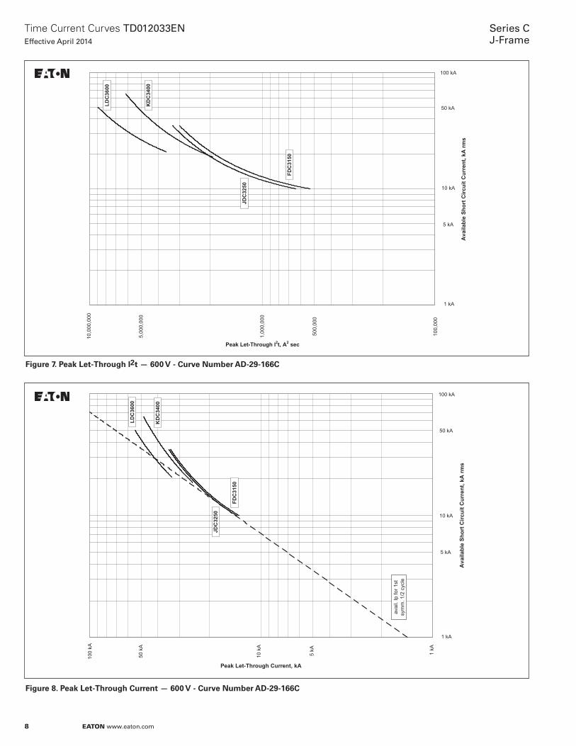
Figure 7. Peak Let-Through I2t — 600 V - Curve Number AD-29-166C
Figure 8. Peak Let-Through Current — 600 V - Curve Number AD-29-166C

9
Time Current Curves TD012033ENEffective April 2014
Series CJ-Frame
eaton www.eaton.com
100
10
5
1
0.5
0.1
0.05
0.01
0.005
0.0010.5 1 1.5 2 3 4 5 10
TimeDelaySetting
(s)
INST
0.15
0.2
0.5
1.0
2.0
EARTH LEAKAGE CURRENT IN MULTIPLES OF I n
AVAILABLE PICKUP SETTINGS - 0.03 (4), 0.1, 0.3, 0.5, 1, 3, 10, 30A.
TIME (s)
1 min
Ambient Temp. (250C)
Figure 9. UL Series C K-Frame Circuit breaker Earth Leakage Module, 110-480V - Curve Number TC01212005E, March 2003
Circuit Breaker time/Current Curves
earth Leakage Circuit Breaker - UL
1 . ELFD, JD, and KD earth leakage module 3 and 4 pole . 110 - 480V 60hz .
2 . For application and coordination purposes only . -20C to 50C ambient .
3 . Total clearing times include the response time of the earth leakage module, opening time of the breaker, and interruption of current .
4 . Pickup setting of .03A only available with instantaneous time delay .
*Curves do not apply to single phase applications .

10
Time Current Curves TD012033ENEffective April 2014
Series CJ-Frame
eaton www.eaton.com
100
10
5
1
0.5
0.1
0.05
0.01
0.005
0.0010.5 1 1.5 2 3 4 5 10
Time DelaySetting
(s)
INST
0.06
0.1
0.25
0.5
1.0
TIME (s)
1 min
EARTH LEAKAGE CURRENT IN MULTIPLES OF I n
Ambient Temp. (250C)
AVAILABLE PICKUP SETTINGS - 0.03 (4), 0.1, 0.3, 0.5, 1, 3, 10, 30A.
Figure 10. IEC Series C K-Frame Circuit breaker Earth Leakage Module, 110-480V - Curve Number TC01212006E, March 2003
Circuit Breaker time/Current Curves
earth Leakage Circuit Breaker - IeC
1 . ELFD, JD, and KD earth leakage module 3 and 4 pole . *110 - 480V 50hz .
2 . For application and coordination purposes only . -20C to 50C ambient .
3 . Total clearing times include the response time of the earth leakage module, opening time of the breaker, and interruption of current .
4 . Pickup setting of .03A only available with instantaneous time delay .
*Curves do not apply to single phase applications .

11
Time Current Curves TD012033ENEffective April 2014
Series CJ-Frame
eaton www.eaton.com

Eaton1000 Eaton BoulevardCleveland, OH 44122United StatesEaton .com
© 2014 EatonAll Rights ReservedPrinted in USAPublication No . TD012033EN / KDCApril 2014
Eaton is a registered trademark .
All other trademarks are property of their respective owners .
Series CJ-Frame
Time Current Curves TD012033ENEffective April 2014