Embed Size (px)
Citation preview

Time 2Revise Engineering
Level 2 Engineering AwardThe Engineering world.

Level 2 Award in Engineering
Name: _________________________________________
Start date: _________________________________________
Exam Date: ________________________________________
Exam Time: ________________________________________
Target grade: ________________________________________
2

Content………………………………………………………………………..PageAbout this unit1.1 Engineering Sectors and products 51.2 Mechanical and electrical/electronic engineering processes 61.2.1 Machining processes 71.2.2 Forming processes 8-161.2.3 Fabrication processes 17-201.2.4 Electrical/electronic processes 21-231.3 Scales of production 241.3.1 One-off production 251.3.2 Batch Production 261.3.3 Mass Production 271.3.4 Continuous Production 281.4 Modern production methods 291.4.1 Robots 29-341.4.2 Computer numerically controlled (CNC) machinery 351.5 Materials and their processing in engineering 361.5.1 Modern composite Materials 361.5.2 Metallic foams 371.5.3 Material processing 381.6 New Technologies in engineering 391.6.1 Optical fibres 391.6.2 Hydrogen fuel cells 401.6.3 Surface nanotechnologies 411.6.4 Telematics 421.6.5 Blended wing bodies 431.6.6 Bionics 441.7 Sustainable engineered products 451.7.1 Life cycle assessment 45-471.8 Minimising waste production in engineering 481.8.1 The four “R’s” 481.9 Lean manufacturing 491.9.1 Just-In –Time manufacturing 491.9.2 Kaizen 501.9.3 Poka-Yoka 511.10 Renewable sources of energy in engineering 521.10.1 Wind energy 521.10.2 Solar energy 531.10.3 Hydro energy 541.10.4 Geothermal energy 55
3

As you work through the guide use the traffic lights to record your progress.
Red You have developed a good understanding of content- Can select relevant theory to help support an answer.
Amber You are able to explain why points made are important- Develop a line of argument- Reach a logical conclusion by using theory to address
the questionGreen You are confident using engineering theory in a range of
real world contexts and to help form supported judgementsAble to analyse real engineering scenarios in response to extended questionsReach justified conclusions
4

1.1 Engineering Sectors and productsIntroduction: This topic will introduce you to some key engineering sectors , as well as a variety of products associated with them. You will need an understanding of these when you are choosing your career
Engineering Sector
Description Typical products
Aerospace The design, development and manufacture of productsthrough flight
Military aircraft, passenger jets, helicopters and rockets
Automotive The design, development and manufacture of vehicles Cars, motorbikes, commercial vans and lorries
Communications The way information is used around the globe Mobile phones, routers, satellites and computers
Electrical/electronic
The design, development and manufacture of electrical/electronic products
Televisions, Blue –ray players, calculators and microwaves
Mechanical This is a branch of engineering that can be found in many different sectors and is associated with the design, manufacture and testing of machines and other mechanical devices
Engines, robots, lifts and machine tools
Biomedical This is a sector that specialises in developingdevices/procedures that solve medical problems using science and engineering knowledge
Artificial limbs, medical instruments,magnetic resonance imaging(MRI) systems and bulletproof vests
Chemical The design and processing of equipment for the chemical industry as well as the manufacture of chemical products
Petroleum, medicines, cleaning fluids and a range of foods
5

1.2 Mechanical and electrical/electronic engineering processesIntroduction: In todays society, engineers need to have an understanding of the range of processes that will help them produce products or partsthat perform a required function. This topic will introduce you to some of the main processes used to make or assemble products that meet the needs of customers and manufacturers, and will also outline important health and safety considerations
1.2.1 Machining processes
TurningTurning involves the use of a lathe to produce a given shape, usually cylindrical. Lathes have one thing in common: the work piece is held in a chuck and rotated while being machined to shape and size using a cutting tool.
Turning
Machining operations that are carried out on the metal lathe:
6
Operation Description
Facing off Removing material from the end of a workpiece to leave a flat or square surface
Drilling Removing material from the inside of a workpice using a drill bit
Parallel turning Removing material from the outer diameter of the workpiece whist maintaining the same size along its length
Taper Turning A process used to create a conical shape by feeding a tool at an angle to the length of the workpiece
Parting off Parting uses a blade like cutting tool plunged directly into the workpiece to cut off the workpiece at a specific length. It is normally used to remove the finished end of a workpiece from the bar stock that is clamped in the chuck
Knurling Knurling is a manufacturing process, typically conducted on a lathe, wherebya pattern of straight, angled or crossed lines is cut or rolled into the material

1.2.1 Milling Machine
This is a process used to shape products by removing excess material to produce a range of simple and complex shapes. A milling machine has a spindle that holds a rotating cutter in place. The work piece will be clamped to a table or held in a vice and fed under the cutter to form the desired shape. There are two main types of milling machine – horizontal and vertical. In many cases, a universal milling machine combines both horizontal and vertical processes
The milling tool has a screw thread at one end. This is turned into the chuck. A cloth is wrapped around the tool before this is done as it can easily cut through flesh. Care must be taken when setting up a cutting tool.
1.2.1 Drilling Machine
Is a process that creates circular holes in a work piece. The cutting device is called a drill bit. It usually has a shank that allows it to be held in a drilling machine. To drill a satisfactory hole in any material, the correct type of drill bit must be used. This is probably the most common machining operation you will perform and it is important that you do it correctly. Good quality drill bits can be expensive but key to good drilling is keeping the cutting edge sharp.
1.2.1 Safety using secondary machines
Accidents during secondary machining processes are usually caused by:• Loose clothing snagging in a revolving part• Flying pieces of material(swarf) entering the eye.• The hand or arm coming in contact with revolving surfaces/parts• Minor burns from hot material surfaces
Make sure that you follow the correct procedures and wear the right personal protective equipment(PPE) for each process( e.g. goggles and overalls/aprons) , and ensure guards are in the correct position prior to any machining operation. Above all, listen to your teacher when they are demonstrating the correct use of a piece of equipment.
7

1.2.2 Forming processes
Sometimes complex shapes such as engine blocks, tools and equipment cannot be achieved through traditional secondary machining processes. The two main forming processes that allow these parts to be made are casting and forging.
Casting
Casting is a process that usually involves pouring or injecting a liquid metal into a mould. The mould contains a cavity that takes the shape of the desired object, where the metal is allowed to cool and solidify. The casting is removed from the mould and may require secondary machining to create the finished product, depending on the type of casting process used.
Advantages of casting
Intricate shapes can be produced
A good surface finish can be produced
Little or no waste is produced
Large hollow shapes can be produced
8

1.2.2 Sand casting
Sand casting is used for large parts where dimensional accuracy is not as important as other features, e.g. manhole covers.
Sand casting, also known as sand moulded casting, is a metal casting process characterized by using sand as the mould material. The term "sand casting" can also refer to an object produced via the sand casting process. Sand castings are produced in specialized factories called foundries.
A specialised part of the manufacturing/engineering world is casting or foundry work as it is properly called. In schools and colleges this usually involves casting molten aluminium. Before any casting can take place a wooden pattern is made precisely. This is called pattern making and in industry this is a very skilful job. Any inaccuracy at this stage will result in the final cast being wrong or even failing. In schools the pattern is usually made from a softwood and its sides are given a draft (an angle) so that it can be removed from the sand easily.
9

1.2.2 Semi-permanent and permanent mould casting
Permanent mould casting
Used for products that require use with water pressure and in larger quantities than sand casting as tooling costs are relatively high, e.g. pressure valves.
Permanent mould casting is metal casting process that employs reusable moulds ("permanent moulds"), usually made from metal. The most common process uses gravity to fill the mould, however gas pressure or a vacuum are also used.
A variation on the typical gravity casting process, called slush casting, produces hollow castings. Common casting metals are aluminium, magnesium, and copper alloys. Other materials include tin, zinc, and lead alloys and iron and steel are also cast in graphite mould
10

1.2.2 Semi-permanent and permanent mould casting
Semi-permanent mould casting
Semi-permanent mould is a casting process - producing Aluminium alloy castings - using re-usable metal moulds and sand cores to form internal passages within the casting. Moulds are typically arranged in two halves - the sand cores being put into place before the two halves are placed together. The molten metal flows into the mould cavity and surrounds the sand core while filling the mould cavity. When the casting is removed from the mould the sand core is removed from the casting leaving an internal passage in the casting.
The re-usable metal moulds are used time and again, but the sand cores have to be replaced each time the product is cast, hence the term semi-permanent moulding.
Semi-permanent moulding affords a very high precision quality to the casting at a reduced price compared to the sand casting processes.
11

1.2.2 Investment casting
Used for parts that requires close dimensional tolerances and complex shapes such as compressor wheels for automotive turbochargers.Investment casting is an industrial process based on and also called lost-wax casting, one of the oldest known metal-forming techniques. From 5,000 years ago, when beeswax formed the pattern, to today’s high-technology waxes, refractory materials and specialist alloys, the castings allow the production of components with accuracy, repeatability, versatility and integrity in a variety of metals and high-performance alloys. Lost-foam casting is a modern form of investment casting that eliminates certain steps in the process.
There are a variety of materials that can be used for the investment casting process, including stainless steel alloys, brass, aluminium, and carbon steel. The material is poured into a ceramic cavity designed to create an exact duplicate of the desired part. Investment casting can reduce the need for secondary machining by providing castings to shape.
Investment casting derives its name from the pattern being invested (surrounded) with a refractory material. The fragile wax patterns must withstand forces encountered during the mould making. Much of the wax used in investment casting can be reclaimed and reused.
The process is generally used for small castings, but has been used to produce complete aircraft door frames, steel castings of up to 300 kg (660 lbs) and aluminium castings of up to 30 kg (66 lbs). It is generally more expensive per unit than die casting or sand casting, but has lower equipment costs. It can produce complicated shapes that would be difficult or impossible with die casting, yet like that process, it requires little surface finishing and only minor machining.
12

1.2.2 Die Casting
Used for large quantities of parts that require a close tolerances as tooling costs are quiet high, e.g. toy cars
Die casting is a metal casting process that is characterized by forcing molten metal under high pressure into a mould cavity. The mould cavity is created using two hardened tool steel dies which have been machined into shape and work similarly to an injection mould during the process.
13

1.2.2 Forging
Forging is a process that involves a metal being heated up and shaped by plastic deformation. It is usually achieved by applying some kind of squeezing force(compression) such as hammer blows using a large power press. Forging improves the physical properties of a metal by changing the direction of the grain flow to improve strength, toughness and ductility. As with casting, forging can be achieved in a number of ways:
Drop forging
Produces a range of small to medium sized shapes with good dimensional accuracy and high production rates through hammering in a closed die, e.g. engine camshafts
14

1.2.2 Press forging
Uses a slow squeezing action to form the metal that penetrates the whole object making it suitable for forging large objects, e.g. aircraft landing gear.
Press forging is a method of forging that involves the slow and continuous application of pressure on the work piece. This method differs greatly from the heavy and quick blows used in drop and hammer forging
15
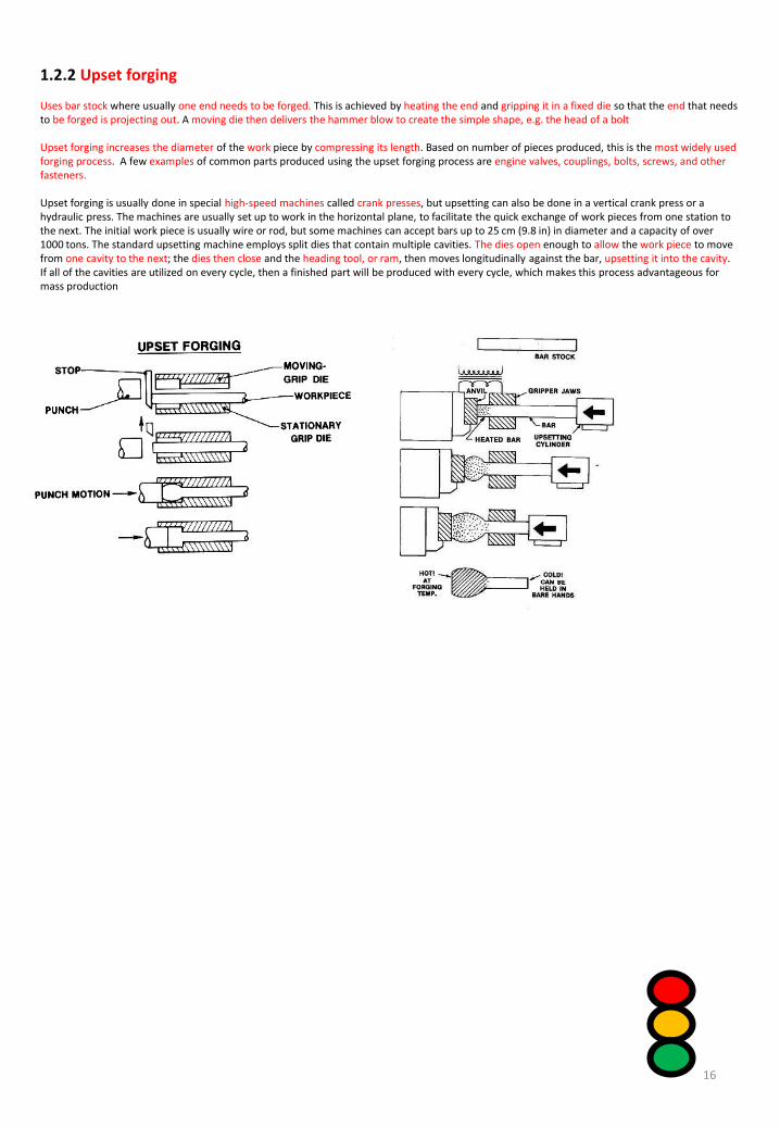
1.2.2 Upset forging
Uses bar stock where usually one end needs to be forged. This is achieved by heating the end and gripping it in a fixed die so that the end that needs to be forged is projecting out. A moving die then delivers the hammer blow to create the simple shape, e.g. the head of a bolt
Upset forging increases the diameter of the work piece by compressing its length. Based on number of pieces produced, this is the most widely used forging process. A few examples of common parts produced using the upset forging process are engine valves, couplings, bolts, screws, and other fasteners.
Upset forging is usually done in special high-speed machines called crank presses, but upsetting can also be done in a vertical crank press or a hydraulic press. The machines are usually set up to work in the horizontal plane, to facilitate the quick exchange of work pieces from one station to the next. The initial work piece is usually wire or rod, but some machines can accept bars up to 25 cm (9.8 in) in diameter and a capacity of over 1000 tons. The standard upsetting machine employs split dies that contain multiple cavities. The dies open enough to allow the work piece to move from one cavity to the next; the dies then close and the heading tool, or ram, then moves longitudinally against the bar, upsetting it into the cavity. If all of the cavities are utilized on every cycle, then a finished part will be produced with every cycle, which makes this process advantageous for mass production
16

1.2.3 Fabrication processes
WeldingMore often than not, engineered products or parts need to be joined together in some way. Sometimes the solution is a simple nut, bolt and washer, but on other occasions a more permanent method is required. Welding is one of the most efficient methods of permanently joining two pieces of metal together. It can be done in many different ways but most methods use intense heat to fuse the metal together. A number of energy sources – a gas or electric arc, laser or ultrasound – can be used.
MIG Welding
This is probably the most common industrial welding process. It uses electricity to generate the heat required to weld materials. MIG stands for Metal Inert Gas
Advantages:
• Suitable for large scale production• Varying thicknesses of materials can be joined• Reduced cost because the production of heat neat and clean metal deposits on the work piece means there is no need for extra cleaning
17

1.2.3 Fabrication processes
OXY-acetylene
A gas welding process where a flame is produced using a mixture of oxygen and acetylene. No pressure on the product is required – the heat is there to control the welding of the parts.
Advantages:
• Ease of controlling the low and high temperatures needed for welding, brazing and soldering as the gas can be mixed manually• Relatively inexpensive in comparison with other welding processes and commonly found in school or college workshops
18

1.2.3 Fabrication processes
Spot welding
A type of electrical resistance welding generally used to join sheet material together. The basic principle uses a transformer with a primary winding and secondary winding connected to copper electrodes. When two electrodes trap the sheet material they generate enough heat to fuse the two together.
Advantages:
• The process is free from fumes or spatter• Requires little or no maintenance• Cost effective
19

1.2.3 Fabrication processes
Shearing
This is a process used to cut straight lines on a range of materials from sheet metal to angle and bar stock. An upper blade and a lower blade are forced past each other with a space between them determined by a required offset. Usually, one of the blades is stationary.Materials that is commonly sheared include aluminium, brass, mild steel and stainless steel.
20

1.2.4 Electrical/electronic processes
Circuit board manufacturing is a massive worldwide industry and circuit boards feature in all the high tech gadgets we use every day.
Printed circuit board (PCB) manufacture
Printed circuit boards come in all shapes and sizes. Some are very simple, others often extremely complex. To manufacture a circuit board you will need to work through some, if not all, of the following basic steps:
1. Designing the layout
Usually circuit boards are designed using computer software, Many packages allow you to construct circuits and position components. Alternatively, layouts can be drawn on paper or directly onto your board to ensure components will fit correctly.
2. Producing the artwork
If you are using computer software, your circuit diagram can be converted to a black and white image showing the component positions and the connecting tracks. This is known as “artwork” and needs to be printed onto clear acetate material. Check that your printer supports the use of clear acetate first as it can damage some machines.
3. PCB etching
You then need to transfer the track and component layout to the copper-covered board. If you are making the PCB yourself you can draw the tracks straight on to the board using an etch-resistant pen. If you are using printed clear acetate you will need a photo etch board and an ultraviolet(UV) light box. Peel the protective covering from the board to expose the sensitive surface, place the artwork on it and put the board with the clear acetate between the board and the light. The artwork must be the correct way up or your circuit will be produced the wrong way around. Close the lid and switch the machine on to expose the board to the UV light for around two and a half minutes. From this point on, you will need to use plastic tongs as you are dealing with chemical solutions. Place the board in a developer solution and remove it after 10 seconds. Then place it in a solution of ferric chloride( an etching solution) until all the exposed copper is etched away. After PCB etching you are left with the copper tracks and component positions that make up your circuit.
4. Drilling the board
After etching , carefully drill the circuit board at the points indicated to mount your components. Accuracy is vital – an incorrectly drilled hole may cause your circuit to fail.
5. Populating the board and soldering
Finally, place the components in the correct positions and solder them in place. Again, take care when doing this, as you can easily mount a component in the wrong place or even on the wrong side of the board. Use your layout drawing as a guide.
21

1.2.4 Electrical/electronic processes
The steps of PCB manufacturing
Printed circuit board (PCB) Manufacture
1. Designing the layout
2. Producing the artwork
3. PCB etching
4. Drilling the board
5. Populating the board and soldering
22

1.2.4 Electrical/electronic processes
Surface Mount Technology
High-volume industrial PCB manufacture is achieved through a process called Surface Mount Technology or SMT. Virtually all of todays mass-produced electronic products are manufactured this way. SMT was developed in the 1960’s but became more widely used in the 1980’s. The process involves attaching electrical components to the surface of a conductive board rather than drilling holes for component legs.
Advantages of SMT
Components much smaller and lighter
Reduced cost of components, labour , protection,
overheads
Reduced human intervention – process highly automated
Complex circuits produced on small boards
Increased production speeds
The SMT Process
1. Apply solder paste to copper pads
2. Place components using pick and place robot
3. Conveyer belts are used to transport the boards to the
reflow soldering oven
4. The boards are heated to a temperature that melts the
solder paste
6.The finished board is then inspected for imperfections
The SMT Process
5. Components are soldered to the surface of the board
23

1.3 Scales of Production
When manufacturing products, the quantity required will determine which production method is used. This is referred to as “scalesof production”. Sometimes a large quantity may be needed so a production line might have machinery and equipment set up to make the same product over and over again. If a smaller quantity is required then it may mean that the production line is designedso that it can be changed to make different products
Mass ProductionQuantity of 10,000+CarsElectronic goods – phones, kitchen electricalFlat-pack furniture
Batch ProductionQuantity low 100’s, maybe low 1000’sPotteryBreadFurniture (sofas)
One-Off Production (Bespoke)Quantity of 1Jewellery Made to measure suitSpecialist equipment for elite sportsman
One-off Batch Mass Continuous
Unit cost High Medium Low Low
Tools and equipment
General Specialised Specialised and dedicated
Specialised and dedicated
Initial investment
Low Medium High High
Production efficiency
Low Medium/high High Very high
Labour type Skilled Skilled/semi-skilled
Semi-skilled/unskilled
Unskilled
Labour cost High Medium Low Low
24

1.3.1 One-off Production
One-off production is where you make a single product.
This is often made to an individual design for one customer, such as ‘custom-made’ furniture.
One-off products are often made by hand by skilled craftsmen.
One-off products are normally expensive, because of the amount of time taken to make them.
Summary:
• Products are highly specialised, custom built
• High level of skill required
• Costs extremely high
• Can reliability ensure very high quality of build and finish
25

1.3.2 Batch Production
Batch production makes small quantities, from a few hundred to a few thousand, depending on the type of product.
Each batch of products will have the same design. However, different batches might be customised in some way. For example, the same design might be made in a different colour or size.
Batch production normally uses machine tools, and costs less to make products than with one-off manufacture, because you don’t have to spend as much time setting up machines to make each product.
Summary:
Products are produced intermittently – with gaps between productionRelatively small volume producedUses some industrial methods, and makes good use of CAD/CAMResponds to demand from consumerSystems are often flexible (make more than one version or type)
26

1.3.3 Mass Production
Mass production makes very large quantities of the same product. Most things that you use every day are mass produced.
Mass production is usually carried out on an assembly line. This is a collection of machines, often robots, that are just used to make that product. Each machine will just do one thing to the product, before passing it on to the next one.
The cost of setting up a production line is very high, so you have to make large quantities of a product to pay for it. Machinery and tooling is often very expensive and specialist.
Summary:
Products are produced at high volume, cheaply.Increased automated systemsHuge investment needed. Initial set up costs high…long term cost low
27

1.3.4 Continuous Production
Continuous production is used to make products like steel, oil or chemicals.
Many of these products are used as the materials to make other products. Factories that operate continuous production often run 24 hours a day, seven days a week. The process needs to be continuous because it would be very expensive to stop it and then turn it on again.
28

1.4 Modern Production MethodsIntroduction
New sophisticated production methods have helped to transform manufacturing in terms of speed , accuracy and efficiency. Not so long ago, many processes were carried out manually, which had a large impact on the price of goods because of the number of hours taken to produce a product or series of products. Today, many of the same products are manufactured using highly automated systems, often requiring a different type of labour force.
1.4.1 Robots
Although you may think of a robot as something resembling a human being, robots can come in all shapes and sizes, and are already very much part of the manufacturing industry around the world. So what exactly are they? Robots are usually mechanical devices that can move in every direction using sophisticated electronics to control that movement. “Robot” is a Czech word that simply means “worker”. They were first used in the 1960’s to carry out hazardousoperations, including handling radioactive and toxic materials.Many organisations rely on robots to produce their products cheaply, accurately and consistently over long periods of time. This is possible if there are processes in place to monitor the performance of each and every robot.
29

Advantages of robots
1. Robots can perform the tasks which the humans find dangerous , boring or difficult , They can do the work with constant speed and precision , and they continue and finish the work without feeling sick .
2. Robots can be programmed to perform a simple task , they repeat that task more times , the robots work in the factory with high degree of accuracy , and they work with constant velocity .
3. Robots help increase the number of manufactured products and decrease the production of defective goods , they can produce the same quality products during the production process , they do not get exhausted , and they work for a long period of time .
4. Robots can be used in the computer industry , they are used in all kinds of electronics from the radios to the microwaves , they are used in packaging , they are used in producing the food , textiles and the drugs .
5. Robots help in doing dangerous jobs ? They can work at a constant speed without sleep , breaks, vacations , salaries , and they can produce more than the human workers .
6. Robots can perform dangerous applications in hazardous settings , They minimize the materialwaste , they can save the time and effort , and their movements are always exact .
7. Robots help increase the productivity in the factories , they made the businesses achieve morebenefits , they can reduce the companies loss , they are used in dangerously polluted environments such as the chemical spills and radioactive in the nuclear power plants , and they are used in the radioactive waste clean-up .
8. Robots have more precise guidance in doing the tasks , they are linked to the powerful computers or controllers , they contain machine vision sub-systems acting as their visual sensors , so , they are more flexible to the orientation of objects that they can perform the tasks on them .
30

Disadvantages of robots
1. Industries prefer utilizing the robots rather than the human workers , So , the unemployment rate will increase , and many people who can not get work will become poorer while the companyowners will get richer .
2. Companies should calculate the cost of the robotic automation in light business , It sometimes costs a lot of money greater than the financial budget , and they need regular maintenance which costs a lot of money .
3. Robots can work in the factory with limitations , The human do the tasks that require creativity , decision-making , adaptation , and job learning .
4. If the employees have no experience to deal with the robots , they will need training program to interact with the new robotic equipment , it will take time and cost a lot of money in the financialoutput .
5. Robots can protect the human workers from some hazards , The robots can create other safety problems , and they can cause new dangers which must be taken in consideration .
6. Companies must plan before using the industrial robots as using the robots without planning in the factories does not guarantee the results , so the companies will have the difficulty to achieve their goals . Very high initial start up cost.
7. Robots can produce lots of electronic wastes ? They can not do something which they do not designed to do , and they make people lazy
31

1.4 Modern Production Methods
Exploration using robots
Space exploration and search for ships lost at the bottom of the ocean have been made possible through the use of remote operated vehicles(ROV’S). Fitted with cameras and sensory devices, they allow personnel to control the vehicle well away from any danger at the site of exploration.
32

1.4 Modern Production Methods
Assembly using robotsManufacturing systems use robotic arms to perform dangerous tasks such as welding the frame of a car and spray painting parts without endangering the life of the workers.
33

1.4 Modern Production Methods
Packaging and dispatch using robotsHave you ever wondered how all airport baggage is sorted and arrives, more often than not, at the correct destination? Airports use highly complex programmable logic controller’s(PLC’s) to controlthe movement of the baggage through a series of sensors cameras and conveyer systems
34

1.4.2 Computer numerically controlled (CNC) machinery
A CNC machine uses programming information to automatically execute a series of machining operations. For example, a CNC milling machine has the same basic functions as a traditional milling machine but it also has a computer that controls the spindle and the movement of the table, allowing for a range of shapes and forms to be cut accurately. Most CNC Machines also have a facility that will monitor and detect any wear in the cutting tool as a result of continuous use and adjust or change the tool automatically without stopping production.Today CNC machining is often referred to as computer-aided manufacturing(CAM). This is essentially the same type of machine but CAM usually relies on the use of computer-aided design (CAD) programmes to create drawings of products that can be directly converted to the CAM machines for manufacture. This impacts on the speed of production and the accuracy and consistency of the finished engineered products. These benefits come at a cost as the software and machines, together with the necessary maintenance and training , are very expensive. But organisations striving to improve their product and production quality should see this as a good investment for the future.
Advantages of Using CAD/CAM
There are a number of important advantages and disadvantages in using 2D and 3D CAD/CAM. The main advantages are:
• speed, particularly in terms of experimentation and communication• accuracy (i.e. fewer mistakes), particularly when things are copied• sharing of data• ease of storage and access• increased productivity
Disadvantages of Using CAD/CAM
There are also a number of disadvantages.
• Computer technology is expensive to buy and maintain.• Using computer technology requires a lot of training and experience.• There is a lack of opportunity to experiment with real materials and 3D forms.• It is easy to lose data if files are not regularly ‘backed up’.
35

1.5 Materials and their processing in engineering
Introduction
Why do we need such a range of modern materials? The answer lies in the function or purpose of the engineered products and properties and the properties they need to be successful. You will need an understanding of these materials and processes before you decide how to manufacture an engineered product
1.5.1 Modern Composite MaterialsMaterials and their properties and uses
Material Properties/characteristics Application/uses
Modern composite materials
Glass reinforced plastic (GRP)
1. Good strength-to-weight ratio,2. Easily moulded/shaped, 3. Resistant to corrosion, 4. Durable, 5. Electrical insulator,6. Relatively inexpensive
Garage doors, boats and custom moulding to produce furniture
Carbon fibre 1. Amazing strength-to-weight ratio, 2. 2. Easily moulded/shaped, 3. Resistant to corrosion,4. 4. Rigid/stiff, 5. Electrical insulator and quite expensive
Monocoque structures of supercars and specialist bicycle frames
Kevlar 1. High tensile strength-to-low-weight ratio, 2. 2. High chemical resistance, 3. Extremely tough, 4. Very stable and non-flammable
Bulletproof vests, helmets, ropes and cables
High –performance materials
Titanium 1. Low density, 2. 2. High strength, 3. Resistant to corrosion, 4. Low thermal conductivity
Drill bit coatings, golf clubs and medical implants
Ceramics 1. Very hard but brittle, 2. 2. Good wear resistance, 3. 3. Corrosion resistant, 4. Very stable, 5. Chemically inert
Glassware, catalytic converters and electronic components
Super alloys 1. Excellent strength at high temperatures, 2. Very expensive, 3. Resistant to corrosion, 4. Hard wearing
Jet engine turbine blades, valves for piston engines and submarines
Smart materials
Shapememory alloys (SMA)
1. Return to their original shape after heating and deformation,
2. Lightweight, 3. Quite expensive
Spectacle frames, pipe and tube jointing systems
Shape memory polymers
1. Return to their original shape after heating and deformation,
2. Lightweight, 3. Resistant to corrosion
Sportswear, surgical sutures and orthopaedic surgery
Piezoelectric actuators
1.Have an ability to generate electric charge when squeezed or pressed
Sensors, actuators, high voltages and power sources
36

1.5 Materials and their processing in engineering
Key terms:
Composite material – a material that is made from two or more constituents for added strength and toughnessSmart Material – a material that can have one or more of its properties changed in a controlled manner by n external stimulusTensile strength - Tensile strength measures the force required to pull something such as rope, wire, or a structural beam to the point where it breaks.Ductility - is when a solid material stretches under tensile stress. If ductile, a material may be stretched into a wire.Malleability - is a material's ability to deform under pressure (compressive stress). If malleable, a material may be flattened by hammering or rollingHardness - Hardness is a measure of how resistant solid matter is to various kinds of permanent shape change when a compressive force is applied. Its ability to withstand wear and abrasion.Toughness - the ability of a material to absorb energy and plastically deform without fracturing.
37

1.5.2 Metallic foams
A metallic foam is broadly similar to any other type of foam, but is made of metal – usually aluminium. A typical metallic foam will have between 75 and 95% of its structure made of pores or spaces that can be connected together( open cell foam) or sealed (closed cell foam) which traps gases inside the metal.
Metallic foams are rigid materials and, in a number of cases, they look very much like solid metal until you cut them open or pick them up, as they are very light. Metallic foams have properties that make them very useful for most engineering sectors, particularly the automotive and aerospace sectors.
Advantages• A high strength-to-weight ratio, particularly when aluminium is used• The ability to absorb large amounts of energy when crushed• Being non-flammable in most cases• Allowing the transfer of heat energy easily.
These advantages outweigh the main disadvantages
Disadvantages• Their high cost means that they are only used with advanced technology• Once crushed they do not spring back to shape like polymer foams, therefore they can only be used once
Typical uses of metallic foams
Sound dampening in cars or aircraft to reduce noise for the driver or passengers.Energy absorption to improve safety to passengers of a car are less likely to be injured during a collisionTaking heat from sensitive electronic components to reduce the risk of product failure
38

1.5.3 Material processing
By examining a range of products from different sectors, it is clear that a wide variety of processes are required to get materials to the correct shape before any secondary machining takes place.
These processes include drawing, blending, rolling, casting, moulding, pressing, sintering mixing, calendaring and extrusion.
Powder metallurgy
This is a highly evolved method of producing consistently shaped components by blending elements or pre-alloyed powders together. The powders are then compacted in a die and heated in a controlled furnace atmosphere to bond particles. The process of powder metallurgy includes blending, mixing, pressing and sintering
Advantages of powder metallurgy:
• It can be applied to all classes of materials• It requires relatively low processing temperatures• It produces a uniform microstructure• Complex parts can be produced with precision and close tolerances• The process can be automated, allowing high-volume production• Final products require little or no finishing• There is no waste, so materials are used efficiently-
Sintering
Sintering is a heat treatment applied to a powder compact in order to impart strength and integrity. The temperature used for sintering is below the melting point of the major constituent of the Powder Metallurgy material.After compaction, neighbouring powder particles are held together by cold welds, which give the compact sufficient “green strength” to be handled. At sintering temperature, diffusion processes cause necks to form and grow at these contact points.
There are two necessary precursors before this "solid state sintering" mechanism can take place:-Removal of the pressing lubricant by evaporation and burning of the vapours Reduction of the surface oxides from the powder particles in the compact.These steps and the sintering process itself are generally achieved in a single, continuous furnace by judicious choice and zoning of the furnace atmosphere and by using an appropriate temperature profile throughout the furnace.
39

1.6 New technologies in engineering
IntroductionAs technology moves on, so does the industrial world. This topic will get you thinking about how the invention of new processes and materials helps to develop new products.
1.6.1 Optical fibresOptical fibres are used in a variety of industries, although their greatest success has undoubtedly been in the communications sector. Originally considered to be too expensive for practical applications, optical fibres have since revolutionised the infrastructure of telephone networks. They bring several advantages over the original copper wire.
1. Bandwidth - Fibre optic cables have a much greater bandwidth than metal cables. The amount of information that can be transmitted per unit time of fibre over other transmission media is its most significant advantage.
2. Low Power Loss - An optical fibre offers low power loss. This allows for longer transmission distances. In comparison to copper; in a network, the longest recommended copper distance is 100m while with fibre, it is 2000m.
3. Interference - Fibre optic cables are immune to electromagnetic interference. It can also be run in electrically noisy environments without concern as electrical noise will not affect fibre.
4. Size - In comparison to copper, a fibre optic cable has nearly 4.5 times as much capacity as the wire cable has and a cross sectional area that is 30 times less.
5. Weight - Fibre optic cables are much thinner and lighter than metal wires. They also occupy less space with cables of the same information capacity. Lighter weight makes fibre easier to install.
6. Safety - Since the fibre is a dielectric, it does not present a spark hazard.
7. Security - Optical fibres are difficult to tap. As they do not radiate electromagnetic energy, emissions cannot be intercepted. As physically tapping the fibre takes great skill to do undetected, fibre is the most secure medium available for carrying sensitive data.
8. Flexibility - An optical fibre has greater tensile strength than copper or steel fibres of the same diameter. It is flexible, bends easily and resists most corrosive elements that attack copper cable.
9. Cost - The raw materials for glass are plentiful, unlike copper. This means glass can be made more cheaply than copper.
40

Disadvantages
1. Cost - Cables are expensive to install but last longer than copper cables.
2. Transmission - transmission on optical fibre requires repeating at distance intervals.
3. Fragile - Fibres can be broken or have transmission loses when wrapped around curves of only a few centimetres radius. However by encasing fibres in a plastic sheath, it is difficult to bend the cable into a small enough radius to break the fibre.
4. Protection - Optical fibres require more protection around the cable compared to copper.
41

1.6 New technologies in engineering
IntroductionAs technology moves on, so does the industrial world. This topic will get you thinking about how the invention of new processes and materials helps to develop new products.
1.6.2 Hydrogen fuel cellsHydrogen is a versatile energy carrier that can be used to power most devices. The key to making this happen is the hydrogen fuel cell – an energy conversion device that captures and uses the power of hydrogen efficiently.
Fuel cells are used for the following reasons.• They directly convert the chemical energy in the hydrogen to electricity with pure water and useful heat as the
only waste materials.• They operate very quietly and are very efficient – typically two to three times more efficient than traditional
technologies• Fewer moving parts mean very simple construction and therefore mass production costs are low.
42

1.6 New technologies in engineering
IntroductionAs technology moves on, so does the industrial world. This topic will get you thinking about how the invention of new processes and materials helps to develop new products.
1.6.3 Surface nanotechnologiesThese are chemical systems that provide coatings to a range of surfaces.
• Ceramics – produces hygienic surfaces• Metals- resistant to corrosion• Glass – cleaning process is much less time-consuming• Plastics –easier surface cleaning• Textiles – surfaces become water and dirt –repellent• Minerals – longer lasting materials
In modern times nanotechnology has become increasingly important. It has many uses from developing sports equipment to medical applications. There are however some concerns about its use.Nanotechnology
The use and control of tiny matter is called nanotechnology. The tiny matter is referred to as nanoparticles.These particles are measured in nanometres (nm). A nanometre is one billionth of a metre (0.000 000 001m). Nanotechnology is concerned with the use and control of structures that are 1-100 nanometres in size.Some of these nanoparticles occur naturally, for example in volcanic ash. Some occur by accident, for example during the combustion of fuels. Many occur by design.Properties of nanoparticlesNanoparticles of a material show different properties compared to larger particles of the same material. Forces of attraction between surfaces can appear to be weak on a larger scale, but on a nanoscale they are strong.One reason for this is the surface area to volume ratio. In nanoparticles this is very large. Atoms on the surface of a material are often more reactive than those in the centre, so a larger surface area means the material is more reactive.NanoparticlesNanoparticles have more surface area to volume than larger particles.The diagram shows this idea. The cube on the left has the same volume as the smaller cubes added together on the right. However, the total surface area is much larger for the smaller cubes.
Use of nanoparticles
Nanoparticles are used in products that are currently available.sports equipment: nanoparticles are added to materials to make them stronger whilst often being lighter. They have been used in tennis rackets, golf clubs and shoesclothing: silver nanoparticles have been added to socks. This stops them from absorbing the smell of sweaty feet as the nanoparticles have antibacterial propertieshealthcare: nanoparticles are used in sunscreens. They offer protection and can be rubbed in so there are no white marks.Harmful effectsThere are some concerns that nanoparticles may be toxic to people. They may be able to enter the brain from the bloodstream and cause harm. Some people think more tests should take place before nanoparticles of a material are used on a wider scale.
43

1.6 New technologies in engineering
IntroductionAs technology moves on, so does the industrial world. This topic will get you thinking about how the invention of new processes and materials helps to develop new products.
1.6.4 TelematicsTelematics is a combination of telecommunications and information communications technology(ICT). This technology has improved the efficiency of many organisations but has had the most impact when used in vehicles across the world using Global Positioning Systems(GPS) technology
44

1.6 New technologies in engineering
IntroductionAs technology moves on, so does the industrial world. This topic will get you thinking about how the invention of new processes and materials helps to develop new products.
1.6.5 Blended wing bodies
As rising fuel costs and pressure to cut emissions drive most of the aerospace industry t seek even small improvements in aircraft efficiency, the development of blended wing bodies has seen fuel consumption reduced by up to a third.This hybrid design uses the wings of a conventional aircraft smoothly blended into a wide tailless body. With the airframe as smooth as possible, this reduces turbulent airflow, thus reducing drag. Combined with the use of lightweight composite materials, this improves the fuel efficiency of the aircraft.
45

1.6 New technologies in engineering
IntroductionAs technology moves on, so does the industrial world. This topic will get you thinking about how the invention of new processes and materials helps to develop new products.
1.6.6 Bionics
This is the science of applying electronic principles and devices, such as computers and miniaturised circuits, to solve medical problems. An example is the development of artificial pacemakers to correct abnormal heart rhythms or the development of prosthetic limbs using a Bluetooth connection and specially enabled software to control the limb movement
46

1.7 Sustainable engineered products
IntroductionEngineering and manufacturing have helped raise living standards in some parts of the world, but at what cost? There are concerns about effects of the depletion of the earths natural resources as modern lifestyles require huge amounts of energy, much of which is still produced from fossil fuels. Producing sustainable products will help to conserve the earth’s resources.
1.7.1 Life cycle assessment
Life cycle assessment (LCA) is probably the most important for assessing the overall environmental impact of products and processes from design to disposal. This system looks at the entire life cycle of a product or process, and maps its environment footprint.
When carrying out this assessment you should consider the impact of the product and its production processes at the following stages;• Raw material extraction• Material production• Production of parts• Assembly of products• The product use• Product disposal recycling
LCA is carried out firstly by creating a list of all the inputs and outputs to the product or process, and then evaluating the environmental impacts of each one. These results can then be used to set specific objectives for an organisation in terms of reducing its environmental footprint.
47

VariantsCradle-to-graveCradle-to-grave is the full Life Cycle Assessment from resource extraction ('cradle') to use phase and disposal phase ('grave'). For example, trees produce paper, which can be recycled into low-energy production cellulose (fiberised paper) insulation, then used as an energy-saving device in the ceiling of a home for 40 years, saving 2,000 times the fossil-fuel energy used in its production. After 40 years the cellulose fibres are replaced and the old fibres are disposed of, possibly incinerated. All inputs and outputs are considered for all the phases of the life cycle.
Cradle-to-gateCradle-to-gate is an assessment of a partial product life cycle from resource extraction (cradle) to the factory gate (i.e., before it is transported to the consumer). The use phase and disposal phase of the product are omitted in this case. Cradle-to-gate assessments are sometimes the basis for environmental product declarations (EPD) termed business-to-business EDPs. One of the significant uses of the cradle-to-gate approach compiles the life cycle inventory (LCI) using cradle-to-gate. This allows the LCA to collect all of the impacts leading up to resources being purchased by the facility. They can then add the steps involved in their transport to plant and manufacture process to more easily produce their own cradle-to-gate values for their products.
Cradle-to-cradle or closed loop productionCradle-to-cradle is a specific kind of cradle-to-grave assessment, where the end-of-life disposal step for the product is a recycling process. It is a method used to minimize the environmental impact of products by employing sustainable production, operation, and disposal practices and aims to incorporate social responsibility into product development. From the recycling process originate new, identical products (e.g., asphalt pavement from discarded asphalt pavement, glass bottles from collected glass bottles), or different products (e.g., glass wool insulation from collected glass bottles).
Allocation of burden for products in open loop production systems presents considerable challenges for LCA. Various methods, such as the avoided burden approach have been proposed to deal with the issues involved.
Gate-to-gateGate-to-gate is a partial LCA looking at only one value-added process in the entire production chain. Gate-to-gate modules may also later be linked in their appropriate production chain to form a complete cradle-to-gate evaluation.
Well-to-wheelWell-to-wheel is the specific LCA used for transport fuels and vehicles. The analysis is often broken down into stages entitled "well-to-station", or "well-to-tank", and "station-to-wheel" or "tank-to-wheel", or "plug-to-wheel". The first stage, which incorporates the feedstock or fuel production and processing and fuel delivery or energy transmission, and is called the "upstream" stage, while the stage that deals with vehicle operation itself is sometimes called the "downstream" stage. The well-to-wheel analysis is commonly used to assess total energy consumption, or the energy conversion efficiency and emissions impact of marine vessels, aircraft and motor vehicles, including their carbon footprint, and the fuels used in each of these transport modes.
48

Well-to-wheelWell-to-wheel is the specific LCA used for transport fuels and vehicles. The analysis is often broken down into stages entitled "well-to-station", or "well-to-tank", and "station-to-wheel" or "tank-to-wheel", or "plug-to-wheel". The first stage, which incorporates the feedstock or fuel production and processing and fuel delivery or energy transmission, and is called the "upstream" stage, while the stage that deals with vehicle operation itself is sometimes called the "downstream" stage. The well-to-wheel analysis is commonly used to assess total energy consumption, or the energy conversion efficiency and emissions impact of marine vessels, aircraft and motor vehicles, including their carbon footprint, and the fuels used in each of these transport modes.
The well-to-wheel variant has a significant input on a model developed by the Argonne National Laboratory. The Greenhouse gases, Regulated Emissions, and Energy use in Transportation (GREET) model was developed to evaluate the impacts of new fuels and vehicle technologies. The model evaluates the impacts of fuel use using a well-to-wheel evaluation while a traditional cradle-to-grave approach is used to determine the impacts from the vehicle itself. The model reports energy use, greenhouse gas emissions, and six additional pollutants: volatile organic compounds (VOCs), carbon monoxide (CO), nitrogen oxide (NOx), particulate matter with size smaller than 10 micrometre (PM10), particulate matter with size smaller than 2.5 micrometre (PM2.5), and sulphur oxides (SOx).
Economic input–output life cycle assessmentEconomic input–output LCA (EIOLCA) involves use of aggregate sector-level data on how much environmental impact can be attributed to each sector of the economy and how much each sector purchases from other sectors. Such analysis can account for long chains (for example, building an automobile requires energy, but producing energy requires vehicles, and building those vehicles requires energy, etc.), which somewhat alleviates the scoping problem of process LCA; however, EIOLCA relies on sector-level averages that may or may not be representative of the specific subset of the sector relevant to a particular product and therefore is not suitable for evaluating the environmental impacts of products. Additionally the translation of economic quantities into environmental impacts is not validated.
Ecologically based LCAWhile a conventional LCA uses many of the same approaches and strategies as an Eco-LCA, the latter considers a much broader range of ecological impacts. It was designed to provide a guide to wise management of human activities by understanding the direct and indirect impacts on ecological resources and surrounding ecosystems. Developed by Ohio State University Centre for resilience, Eco-LCA is a methodology that quantitatively takes into account regulating and supporting services during the life cycle of economic goods and products. In this approach services are categorized in four main groups: supporting, regulating, provisioning and cultural services
49

1.8 Minimising waste production in engineering
IntroductionMinimising waste production in engineering through effective waste management is a key factor in sustainable development. Finding ways to reduce waste usually starts with a focus on the four R’s: reduce, reuse, recycle and recover. In this topic you will find out about each of these methods and how they affect the way we think about the design and manufacture of engineered products.
1.8.1 The “four R’s”
Reduce
This is probably the most important of the “four R’s”: preventing waste in the first place means there is less to dispose of in the end. Organisations need to consider reducing the amount of materials and energy used to manufacture their products. Examples of exploring different formats such as e-books
Reuse
This is probably the next most important consideration because if you can reuse waste material then it will no longer be considered as waste. This will reduce costs of disposal and materials/products can be put to further good use. Examples include giving unwanted clothes to charity shops or stripping an old bicycle down and reusing its parts for another bicycle.
Recycle
Sometimes products can’t be reused. Recycling keeps raw material in the system and slows down the depletion of the earths resources such as fossil fuels and trees. If we keep recycling products then we will cut the amount of materials going to landfill, while also reducing the need to extract gas, coal and oil.
Recover
Sometimes waste has to be disposed of, but finding ways to use this material to produce energy is what recovery is all about. Modern technology allows us to treat waste using thermal and non-thermal processes to produce heat, gas , oil or electricity.
Methods of waste recovery
Methods of waste recovery
Biofuel productionAnaerobic
digestion(ADGasification
Composting Pyrolysis
Methane recovery Incineration
50

1.9 Lean manufacturing
IntroductionJapanese manufacturing techniques have been seen as the way forward in todays competitive business environment. They emerged in the post-World War 2 era and reached a peak in the 19080’s. These techniques have made their way into worldwide manufacturing operations. Their main characteristics include the need to maximise manufacturing efficiencies and improve quality control. This topic will introduce you to some of the most common techniques.
1.9.1 Just-In-Time manufacturing
This involves a strategic approach to the development and operation of a manufacturing system. This means that the production process is organised in a way that ensures parts are available when they are needed.Advantages of this system include:• As products are made to customer orders, there is no overproduction, reducing the build-up
stock or inventory such as raw materials and finished goods• A reduction in stock or inventory also reduces costs as there is less space required for storage
of materials or finished goods• It reduces production cycle times quite drastically through automation and the use of
minimal manpower, further reducing costs• It recognises waste in the movement of materials within an organisation and changes the
layout of the manufacturing line to improve efficiency.
51

1.9 Lean manufacturing
IntroductionJapanese manufacturing techniques have been seen as the way forward in todays competitive business environment. They emerged in the post-World War 2 era and reached a peak in the 19080’s. These techniques have made their way into worldwide manufacturing operations. Their main characteristics include the need to maximise manufacturing efficiencies and improve quality control. This topic will introduce you to some of the most common techniques.
1.9.2 Kaizen
Also known as “continuous improvement”, this is a policy of constantly introducing small changes to improve quality and efficiency. This technique puts the workers at the heart of the decision-making as they are the best people to suggest improvements.
Advantages of this system include the following:
• Improvements are based on small changes rather than large changes as a result of research and development
• As ideas come from the workers they are less likely to be much different than existing processes and are therefore easier to implement.
• Small changes generally do not cost a great deal of money when compared with any major process/production changes.
• It generates workers to take ownership of their work and reinforces team-working, leading to improved worker motivation.
52

1.9 Lean manufacturing
IntroductionJapanese manufacturing techniques have been seen as the way forward in todays competitive business environment. They emerged in the post-World War 2 era and reached a peak in the 19080’s. These techniques have made their way into worldwide manufacturing operations. Their main characteristics include the need to maximise manufacturing efficiencies and improve quality control. This topic will introduce you to some of the most common techniques.
1.9.3 Poka-Yoke
This is a technique for avoiding simplistic human error in the workplace also known as “ mistake proofing” and “fail-safe work methods”. The idea is to take over all the repetitive processes/tasks performed by humans that rely on memory or vigilance and replace them with a simple system to improve productivity and quality.
Advantages of this system include the following:
• Eliminating set-up errors, therefore improving quality• Decreasing set-up time and improving production output• Increased safety as workers do not get injured through lack of concentration• Reduced costs through improved production efficiencies and reducing the need for skilled
labour• Improved motivation of workers, as tasks are not so mundane
53

1.10 Renewable sources of energy in engineering
IntroductionThere is an increasing demand for energy in our fast-developing world. Alternative forms of energy can slow down the depletion of the earths natural resources and safeguard energy supplies for many generations to come.
1.10.1 Wind energyWind is a natural and clean source of renewable energy that produces no air or water pollution. Most wind energy is harnessed through the use of wind turbines. These are usually quite tall structures, sometimes as high as 100m. The largest wind turbines can generate enough electricity to power small towns and villages. Wind farms sometimes contains of turbines and are usually positioned in windy areas, such as mountain ridges, for obvious reasons. Sometimes they are even positioned offshore where the wind can turn huge propellers connected to a generator to produce electricity.Many governments also offer incentives for companies to use this form of energy. However, some people think they are ugly and spoil the surrounding landscape and the constant spinning of the propellers produces noise pollution. This is variable – but where there is no wind, no electricity will be produced.
ADVANTAGES OF WIND POWER:
1. The wind is free and with modern technology it can be captured efficiently.2. Once the wind turbine is built the energy it produces does not cause green house gases or other pollutants.3. Although wind turbines can be very tall each takes up only a small plot of land. This means that the land below can still be used. This is especially the case in agricultural areas as farming can still continue.4. Many people find wind farms an interesting feature of the landscape.5. Remote areas that are not connected to the electricity power grid can use wind turbines to produce their own supply.6. Wind turbines have a role to play in both the developed and third world.7. Wind turbines are available in a range of sizes which means a vast range of people and businesses can use them. Single households to small towns and villages can make good use of range of wind turbines available today.
DISADVANTAGES OF WIND POWER:
1. The strength of the wind is not constant and it varies from zero to storm force. This means that wind turbines do not produce the same amount of electricity all the time. There will be times when they produce no electricity at all.2. Many people feel that the countryside should be left untouched, without these large structures being built. The landscape should left in its natural form for everyone to enjoy.3. Wind turbines are noisy. Each one can generate the same level of noise as a family car travelling at 70 mph.4. Many people see large wind turbines as unsightly structures and not pleasant or interesting to look at. They disfigure the countryside and are generally ugly.5. When wind turbines are being manufactured some pollution is produced. Therefore wind power does produce some pollution.6. Large wind farms are needed to provide entire communities with enough electricity. For example, the largest single turbine available today can only provide enough electricity for 475 homes, when running at full capacity. How many would be needed for a town of 100 000 people?
54

1.10 Renewable sources of energy in engineering
IntroductionThere is an increasing demand for energy in our fast-developing world. Alternative forms of energy can slow down the depletion of the earths natural resources and safeguard energy supplies for many generations to come.
1.10.2 Solar energyMost solar energy is produced through a series of panels that contain photovoltaic cells. These cells convert the heat produced from the rays of the sun into electricity. Over recent years there has been an increase in the use of photovoltaic panels on people’s roofs. The electricity produced can be used to power a home and even heat water directly.Solar panels initially cost thousands of pounds to install, but if you have a south-facing roof they can significantly reduce electricity bills. In fact the government pays householders for any extra energy produced that is fed back into the National Grid. However, some people think that these panels look unsightly. Today, an ever-increasing array of products, such as torches, mobile phones, small solar cell units and outdoor lighting, are powered by solar cells or panels. This is because panels not only produce electricity but are able to store it for the use at night.
Advantages1. Solar energy is free although there is a cost in the building of ‘collectors’ and other equipment required to convert solar energy into electricity or hot water.2. Solar energy does not cause pollution. However, solar collectors and other associated equipment / machines are manufactured in factories that in turn cause some pollution.3. Solar energy can be used in remote areas where it is too expensive to extend the electricity power grid.4. Many everyday items such as calculators and other low power consuming devices can be powered by solar energy effectively.5. It is estimated that the worlds oil reserves will last for 30 to 40 years. On the other hand, solar energy is infinite (forever).
Disadvantages
1. Solar energy can only be harnessed when it is daytime and sunny.2. Solar collectors, panels and cells are relatively expensive to manufacture although prices are falling rapidly.3. Solar power stations can be built but they do not match the power output of similar sized conventional power stations. They are also very expensive.4. In countries such as the UK, the unreliable climate means that solar energy is also unreliable as a source of energy. Cloudy skies reduce its effectiveness.5. Large areas of land are required to capture the suns energy. Collectors are usually arranged together especially when electricity is to be produced and used in the same location.6. Solar power is used to charge batteries so that solar powered devices can be used at night. However, the batteries are large and heavy and need storage space. They also need replacing from time to time
55

1.10 Renewable sources of energy in engineering
IntroductionThere is an increasing demand for energy in our fast-developing world. Alternative forms of energy can slow down the depletion of the earths natural resources and safeguard energy supplies for many generations to come.
1.10.3 Hydro energyWater is another precious natural resource that can generate an unstoppable force.Hydroelectricity is the use of running water – this could be a small stream, a large river or ocean waves – to generate electricity. Streams and rivers flow downhill and as water flows downhill it generated potential energy. Hydropower systems convert this potential energy into kinetic energy using a turbine. As water passes through the turbine, it spins the propeller blades, much like a wind turbine. The turbine is connected to a generator, which produces electricity. The faster the water flow, the more energy is produced.The system usually comes in the form of a hydro dam where turbines are built at the base of the dam and water is released at a controlled rate to generate sufficient power. These systems can work 24hours a day and produce electricity in abundance with no air or water pollution.However , the initial cost of producing a facility to harness this natural resource’s power is high and in periods of drought general water usage will need to be controlled around the country to ensure there is enough water to keep producing electricity.
Advantages1. Once a dam is constructed, electricity can be produced at a constant rate.2. If electricity is not needed, the sluice gates can be shut, stopping electricity generation. The water can be saved for use another time when electricity demand is high.3. Dams are designed to last many decades and so can contribute to the generation of electricity for many years / decades.4. The lake that forms behind the dam can be used for water sports and leisure / pleasure activities. Often large dams become tourist attractions in their own right.5. The lake's water can be used for irrigation purposes.6. The build up of water in the lake means that energy can be stored until needed, when the water is released to produce electricity.7. When in use, electricity produced by dam systems do not produce green house gases. They do not pollute the atmosphere.
Disadvantages1. Dams are extremely expensive to build and must be built to a very high standard.2. The high cost of dam construction means that they must operate for many decades to become profitable.3. The flooding of large areas of land means that the natural environment is destroyed.4. People living in villages and towns that are in the valley to be flooded, must move out. This means that they lose their farms and businesses. In some countries, people are forcibly removed so that hydro-power schemes can go ahead.5. The building of large dams can cause serious geological damage. For example, the building of the Hoover Dam in the USA triggered a number of earth quakes and has depressed the earth’s surface at its location.6. Although modern planning and design of dams is good, in the past old dams have been known to be breached (the dam gives under the weight of water in the lake). This has led to deaths and flooding.7. Dams built blocking the progress of a river in one country usually means that the water supply from the same river in the following country is out of their control. This can lead to serious problems between neighbouring countries.8. Building a large dam alters the natural water table level. For example, the building of the Aswan Dam in Egypt has altered the level of the water table. This is slowly leading to damage of many of its ancient monuments as salts and destructive minerals are deposited in the stone work from ‘rising damp’ caused by the changing water table level.
56

1.10 Renewable sources of energy in engineering
IntroductionThere is an increasing demand for energy in our fast-developing world. Alternative forms of energy can slow down the depletion of the earths natural resources and safeguard energy supplies for many generations to come.
1.10.4 Geothermal energyThis system uses the heat from the rocks in the earth’s inner core that turns water into steam. Engineers drill down into the hot regions and the purified steam rises to drive turbines that produce electricity. Where there is no natural groundwater, cold water can be pumped down to create steam.“Geothermal” comes from the Greek words “ge” meaning “earth” and “therme” meaning “heat”. This form of energy production does not produce any pollution so does not contribute to the greenhouse effect. There is no fuel required to run a geothermal power station and once built, the running costs are very low- just the energy needed to run a pump for cold water, but even that can be taken from the energy being generated.
Advantages1. Significant Cost Saving : Geothermal energy generally involves low running costs since it saves 80% costs over fossil fuels and no fuel is used to generate the power. Since, no fuel is require so costs for purchasing, transporting and cleaning up plants is quite low.2. Reduce Reliance on Fossil Fuels : Dependence on fossil fuels decreases with the increase in the use of geothermal energy. With the sky-rocketing prices of oil, many countries are pushing companies to adopt these clean sources of energy. Burning of fossil fuels releases greenhouse gases which are responsible for global warming3. No Pollution : This is one of the main advantage of using geothermal energy since it does not create any pollution and help in creating clean environment. Being the renewable source of energy, geothermal energy has helped in reducing global warming and pollution. Moreover, Geothermal systems does not create any pollution as it releases some gases from deep within the earth which are not very harmful to the environment4. Direct Use : Since ancient times, people having been using this source of energy for taking bath, heating homes, preparing food and today this is also used for direct heating of homes and offices. This makes geothermal energy cheaper and affordable. Although the initial investment is quite steep but in the long run with huge cost saving it proves quite useful5. Job Creation and Economic Benefits : Government of various countries are investing hugely in creation of geothermal energy which on other hand has created more jobs for the local peopleThough above said advantages prove that geothermal energy has big capability in itself in creating clean and safe environment and also it is an excellent source of cheap, reliable, simple, clean and renewable power but it also suffers from few drawbacks which is why it is not being utilized everywhere to its full capability.
Disadvantages1. Not Widespread Source of Energy : Since this type of energy is not widely used therefore the unavailability of equipment, staff, infrastructure, training pose hindrance to the installation of geothermal plants across the globe. Not enough skilled manpower and availability of suitable build location pose serious problem in adopting geothermal energy globally.2. High Installation Costs : To get geothermal energy, requires installation of power plants, to get steam from deep within the earth and this require huge one time investment and require to hire a certified installer and skilled staff needs to be recruited and relocated to plant location. Moreover, electricity towers, stations need to set up to move the power from geothermal plant to consumer.3. Can Run Out Of Steam : Geothermal sites can run out of steam over a period of time due to drop in temperature or if too much water is injected to cool the rocks and this may result huge loss for the companies which have invested heavily in these plants. Due to this factor, companies have to do extensive initial research before setting up the plant.4. Suited To Particular Region : It is only suitable for regions which have hot rocks below the earth and can produce steam over a long period of time. For this great research is required which is done by the companies before setting up the plant and this initial cost runs up the bill in setting up the geothermal power plant. Some of these regions are near hilly areas or high up in mountains.5. May Release Harmful Gases : Geothermal sites may contain some poisonous gases and they can escape deep within the earth, through the holes drilled by the constructors. The geothermal plant must therefore be capable enough to contain these harmful and toxic gases.6. Transportation : Geothermal Energy can not be easily transported. Once the tapped energy is extracted, it can be only used in the surrounding areas. Other sources of energy like wood, coal or oil can be transported to residential areas but this is not a case with geothermal energy. Also, there is a fear of toxic substances getting released into the atmosphere
57