Embed Size (px)
Citation preview
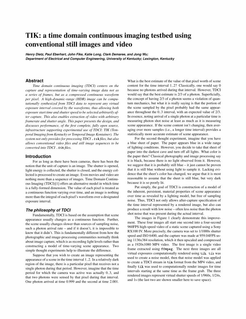
TIK: a time domain continuous imaging testbed usingconventional still images and videoHenry Dietz, Paul Eberhart, John Fike, Katie Long, Clark Demaree, and Jong Wu;Department of Electrical and Computer Engineering, University of Kentucky; Lexington, Kentucky
AbstractTime domain continuous imaging (TDCI) centers on the
capture and representation of time-varying image data not asa series of frames, but as a compressed continuous waveformper pixel. A high-dynamic-range (HDR) image can be compu-tationally synthesized from TDCI data to represent any virtualexposure interval covered by the waveforms, thus allowing bothexposure start time and shutter speed to be selected arbitrarily af-ter capture. This also enables extraction of video with arbitraryframerate and shutter angle. This paper presents the design, anddiscusses performance, of the first complete, fully open source,infrastructure supporting experimental use of TDCI: TIK (Tem-poral Imaging from Kentucky or Temporal Image Kontainer). Thesystem not only provides for processing TDCI .tik files, but alsoallows conventional video files and still image sequences to beconverted into TDCI .tik files.
IntroductionFor as long as there have been cameras, there has been the
notion that the unit of capture is an image. The shutter is opened,light energy is collected, the shutter is closed, and the energy col-lected is processed to create an image. Even movies and video arenothing more than a sequence of images. Time Domain Continu-ous Imaging (TDCI)[1] offers an alternative model in which timeis a fully-formed dimension. The value of each pixel is treated asa continuous function varying over time, and an image is nothingmore than the integral of each pixel’s waveform over a designatedexposure interval.
The philosophy of TDCIFundamentally, TDCI is based on the assumption that scene
appearance usually changes as a continuous function. Further,the scene usually changes slower than sources of sampling noise,such a photon arrival rate – and if it doesn’t, it is impossible toknow that it didn’t. This is fundamentally different from how thephotographic and image-processing communities normally thinkabout image capture, which is as recording light levels rather thanconstructing a model of time-varying scene appearance. Twosimple thought experiments help to illustrate the difference.
Suppose that you wish to create an image representing theappearance of a scene in the time interval 1..2. In a relatively darkregion of the image, there is a particular pixel that receives not asingle photon during that period. However, imagine that the timeperiod for which the camera was active was actually 0..3, andthat two photons were sensed by that pixel during that interval.One photon arrived at time 0.999 and the second at time 2.001.
What is the best estimate of the value of that pixel worth of scenecontent for the time interval 1..2? Classically, one would say 0because no photons arrived during that interval. However, TDCIwould say that the best estimate is 2/3 of a photon. Superficially,the concept of having 2/3 of a photon seems a violation of quan-tum mechanics, but what it is really saying is that the portion ofthe scene sampled by the pixel probably had the same appear-ance throughout the 0..3 interval, with an expected value of 2/3.In essence, noting arrival of a single photon at a particular time ismeasuring photon shot noise at least as much as it is measuringscene appearance. If the scene content isn’t changing, then aver-aging over more samples (i.e., a longer time interval) provides astatistically more accurate estimate of scene appearance.
For the second thought experiment, imagine that you havea blue sheet of paper. The paper appears blue in a wide rangeof lighting conditions. However, you decide to take that sheet ofpaper into the darkest cave and turn off all lights. What color isthe paper then? Classical photography and image processing sayit is black, because there is no light observed from it. However,we suggest that it is probably still blue – it just cannot be proventhat it is still blue without using light to sample it. Lacking evi-dence that the sheet’s color has changed, we argue that it is mostreasonable to assume that the sheet is still blue, but very darkbecause it is so poorly lit.
Put simply, the goal of TDCI is construction of a model ofthe inherent, persistent, material properties of scene appearanceover time as revealed by a lighting model, but free of samplingnoise. Thus, TDCI not only allows after-capture specification ofthe time interval represented by a rendered image, but also canproduce a result with low noise – often less noise than the photonshot noise that was present during the actual interval.
The images in Figure 1 clearly demonstrate this improve-ment. These four images all start one second into a four-second960FPS high-speed video of a static scene captured using a SonyRX100 IV. More precisely, the camera was set to 1/1000s shutterspeed and ISO 6400, and the capture was made at 959.04FPS us-ing 1136x384 resolution, which it then upscaled and compressedas a 1920x1080 MP4 video. The first image is a single videoframe extracted using ffmpeg. The next three images are allvirtual exposures computationally rendered using tik. tik wasused to create a noise model, then that noise model was appliedto create a TDCI stream in tik format from the MP4 video, andfinally tik was used to computationally render images for timeintervals starting at the same time as the frame grab. The threerendered images represent virtual shutter speeds of 1/960s, 1/24s,and 1s (the last two are shown smaller here to save space).
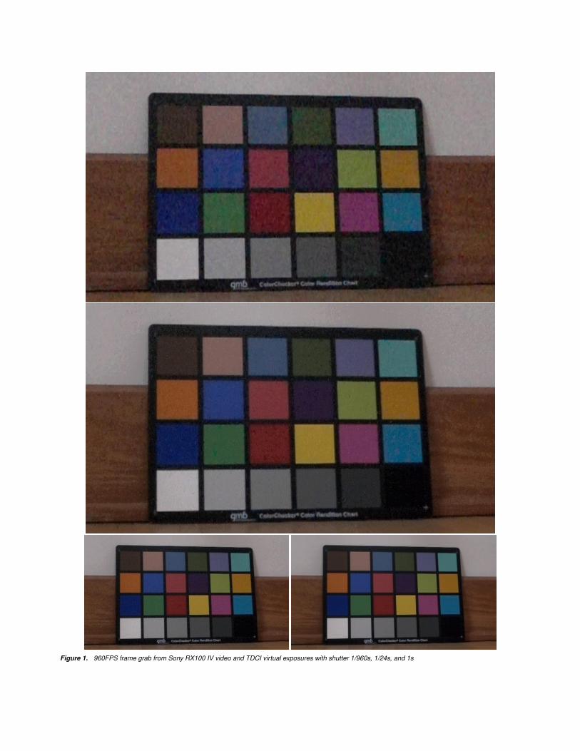
Figure 1. 960FPS frame grab from Sony RX100 IV video and TDCI virtual exposures with shutter 1/960s, 1/24s, and 1s
Although no spatial noise reduction nor post-processing hasbeen applied to the tik-rendered images, the improvement inimage quality over the video frame is obvious. Very conserva-tively using the tik-generated error model (i.e., requiring highconfidence to treat a slightly unexpected value as noise), the av-erage pixel’s value in this video was found to be stable for ap-proximately 7 frames. Thus, although the analysis is done ona per-pixel basis, the 1/960s virtual exposure is obtaining ben-efits very similar to those that would be obtained by averagingover 7 stacked[2, 4] frames. Of course, if there were significantchanges in appearance of any portions of the scene, the pixel val-ues in those portions were not stacked by tik. The quality of thelonger virtual exposures is even higher because they are in effectstacking respectively about 47 and 967 frames each.
To approximately quantify the improvement, a simplesignal-to-noise ratio (SNR) can be computed taking the 1s vir-tual exposure as the reference signal. Computing directly on thepixel values encoded in the JPEG images, the average pixel SNRis roughly 13 for the frame grab, 20 for the 1/960s virtual expo-sure, and 26 for the 1/24s virtual exposure. However, convertingthe JPEG pixel values to a roughly linear gamma, the averagepixel SNR more than doubles going from the frame grab to the1/960s virtual exposure and nearly doubles again going to the1/24s virtual exposure. These improvements are less than onemight expect if conventional stacking were used, but that is a di-rect consequence of the probability threshold having been set tovery conservatively treat much of the sampling noise as actualchanges in the scene appearance. In other words, unlike conven-tional stacking, even scene appearance changes that were wellbelow the average noise level predicted by the noise model canbe preserved.
Implementation of TDCIThere are many benefits to TDCI capture and one giant dis-
advantage: no TDCI cameras yet exist. Construction of a trueTDCI capture camera requires new sensor technology. However,as was suggested earlier[3], many of the benefits of TDCI comefrom the representation of, and computation on, image data in aTDCI format. These benefits can be realized without the need toconstruct a new type of imaging sensor:
• Because the waveform is a smooth curve, it essentially in-terpolates higher-precision values between and across pho-tonic samples; thus, it could provide lower noise and ahigher usable dynamic range
• The virtual exposure interval to be represented by an imagecan be arbitrarily selected after capture as any portion of thewaveform, without concern for the usual APEX exposureconstraints[5]
• Movies can be rendered at any framerate without stutteringartifacts by simply selecting an appropriate virtual exposureinterval for each frame
• The shutter angle can be set arbitrarily; the choice of shutterspeed is decoupled from the choice of framerate
Having laid that theoretical groundwork, the remaining bigquestion about use of TDCI with conventional cameras was sim-ply: do all the details fit? Is it really practical to implement TDCI
using data from conventional cameras? Thus, the goal of this pa-per is completely pragmatic: to explore the details of a completesoftware environment for TDCI.
TIK is an open-source environment and file format specifi-cation intended to support not only use by the research group de-veloping TIK, but also real experiments with TDCI by both otherresearchers and ordinary users of video and still images. Thename TIK is a somewhat strained mnemonic referencing Tempo-ral Imaging from Kentucky or Temporal Image Kontainer (withcontainer deliberately misspelled). The name also suggests pas-sage of time in small units, which is precisely how this systemorganizes time-varying image data. As suggested above, TIK isboth the name of a tool suite and of set of a file formats, whichwould normally be stored in files ending with the .tik suffix.
TIK, the file format(s)One might ask why there should be a new file format as-
sociated with TDCI data; can’t one of the multitude of existingfile formats be used? The answer is that the new .tik file for-mats are precisely that: simple extensions of existing image fileformats. There are two different sets of file formats proposed forTIK data. Work on specifying an "advanced" TIK format, extend-ing the DNG file format[6] to represent raw TDCI data, is not yetcompleted. The "basic" TIK format is geared toward representa-tion of data that has already been processed into a conventionalcolorspace, and it is used for all the work reported in this article.
A basic .tik file is essentially an extension of the widely-supported formats associated with the Netpbm[7] family of tools.For example, those formats are the preferred output of thedcraw[8] raw image converter.
In particular, the Portable Gray Map (PGM) and PortablePixel Map (PPM) formats are extended for TDCI using TIK. Bi-nary PGM files begin with a magic number which is the ASCIIcharacter sequence P5, and PPM files begin with P6. The headerstructure is very simple and also formatted as ASCII characters,allowing simple one-line comments starting with the # charac-ter. Hiding the necessary additional fields in comments that beginwith # TIK provides the obvious benefit that these the extra fieldsare harmlessly ignored (yet faithfully preserved) by most exist-ing tools. However, unlike nearly all other image file formats,because the header is completely expressed as ASCII characters,an ordinary text editor can be used to create and edit headers.In contrast, DNG files extend the TIFF standard, which directlyprovides mechanisms for adding arbitrarily complex fields – butit does not provide any simple way to manage encoding and de-coding the fields that are not normally processed by the particulartool being used to operate on the file.
Why is textual encoding of the header so important for TIK?Sometimes, the header is the entire .tik file. For example, whenprocessing a conventional video file as input, it is still necessaryfor TIK tools to know information including the framerate, shut-ter speed, and even time sequencing of a rolling shutter. Ratherthan devising ways to modify every existing video file format toembed that information, our approach is to simply allow a purelytextual .tik file to provide the needed additional informationabout the contents of one or more files in standard video or stillimage formats.
For .tik files that directly contain any image data, the dataimmediately following the header is always formatted so that itbegins with an image that will be recognized by any tool that un-derstands conventional PGM/PPM files. In this way, loading a.tik file as a PGM/PPM will always provide a preview image.Some tools, such as ffmpeg and ImageMagick display, allowmultiple PGM/PPM files (including their textual headers) to sim-ply be catenated into a single file; our .tik file format allowssuch data to be handled directly. The TDCI compressed formatsstored in .tik files all start immediately after any such conven-tional image data, using a single 0-valued byte as a separatorto render the TDCI data invisible to tools expecting catenatedPGM/PPM data.
TIK file formatsAll of the information about the encoded data in a basic
.tik-format file is specified using structured comments that eachbegin with "#", one or more spaces or tabs, the word "TIK", oneor more spaces or tabs, and then a series of space or tab separatedwords. Each word is either a decimal integer ASCII number or akeyword that does not start with a digit nor negative sign. Theremay be a variable number of words in a structured comment, butthe first word defines how the other words will be treated, and thesequence ends at the the end of the line.
The very first structured comment in a .tik file, normallythe second line of the file, must be a version comment of theform:
# TIK V version format ...The version is an 8-digit number specifying the standard compli-ance date of the TIK encoding. For example, 20160712 wouldmean that the file is formatted as specified by the TIK standardthat was in effect on July 12, 2016. The format specifies which ofdifferent types of encoding is used in the file, and some of thosetypes require additional parameters. At this writing, there are fivedifferent formats.
The first two formats do not actually contain any image data,but are simple textual headers describing ordinary files contain-ing stills or videos:
• 20160721 CONVERT pattern numBegin numEnd – this filespecifies a pattern for naming one or more files, each ofwhich holds image pixel data in any still image format thatthe ImageMagick convert tool can transform into a P6PPM file. The pattern is taken as a format string whichis used with sprintf and one integer parameter to pro-duce each file name. The integer parameter first has thevalue numBegin, and is incremented by 1 each time a fileis processed, ending with the last value not greater thannumEnd. For example, "IMG%05u.JPG 1 4" would at-tempt to process the sequence of images IMG00001.JPG,IMG00002.JPG, IMG00003.JPG, and IMG00004.JPG; ifany image cannot be opened, it will be skipped, but stillcounted against the framerate. For example, if there was noIMG00002.JPG, but the framerate was set as 1FPS, then thethree other frames would be interpreted as spanning time in-tervals from 0..1s, 2..3s, and 3..4s (this behavior can be use-ful for processing timestamped surveillance still captures).
• 20160721 FFMPEG filename – this file specifies the file-name of a video file from which frames can be extractedusing ffmpeg. If filename is omitted, the video filenameis assumed to be the next argument on the tik commandline. In this way, information about a video can be speci-fied without needing to incorporate the information in eachvideo file. The output from ffmpeg is a stream of P6 PPMfiles, one per frame.
The next two formats are representations of TDCI streams:
• 20160712 RGB – the header and initial image are processedlike a normal P6 PPM file. However, after a single 0 byte,the rest of the file consists of a stream of records. Eachrecord encodes the number of pixels whose values are un-changed (within the noise model) from their previously-recorded values as a spatio-temporal span distance and atuple of red, green, and blue (RGB) color channel values forthe unexpected pixel value. The pixels within a frame arescanned either in the usual nest of increasing Y wrappingincreasing X coordinates, or in a sequence determined bythe timing of a rolling shutter. A span distance greater thanthe number of pixels in an image represents entire frames inwhich all pixels had expected values. If the span is 0-127, itis output as a single byte; otherwise, the 7 least-significantbits of span are output in a byte ORed with 0x80, the re-maining span is shifted right by 7 bits, and the process re-peated until no 1 bits remain in span. For example, a spanof 257 pixels followed by an RGB value of 0x11, 0x22,0x33 would be encoded as the five bytes: 0x02, 0x01, 0x11,0x22, 0x33.
• 20160712 UYVYYY – most Canon PowerShot cameras arenot capable of high-framerate video capture, but using theCanon Hack Development Kit (CHDK)[9] to reprogram thecamera, it is possible to record live view data at a relativelyhigh framerate. To minimize in-camera processing, the im-age data is treated as a sequence of P5 PGMs with 6/4 theactual X resolution, thus allowing the native UYVYYY rep-resentation of four pixels to be used directly. This encodingis further complicated by the fact that the YUVYYY val-ues used inside CHDK are unsigned for Y, but signed forU and V, and this is maintained in the TIK file. The U andV color component values are shared by a group of fourpixels; RGB color is computed as:R = min(max(((Y�12)+(V*5743)+2048)�12),0),255)
G = min(max(((Y�12)+(U*1411)+(V*2925)+2048)�12),0),255)
B = min(max(((Y�12)+(U*7258)+2048)�12),0),255)
Finally, the fifth format encodes a statistical model of "error" inpixel values:
• 20160804 NOISE – an ordinary P6 PPM file in which theimage encodes a noise model (see below).
TIK file metadataThe V structured comment is generally followed by a se-
quence of other structured comments that describe important at-tributes of the image data. All number attributes are expressed asintegers to avoid roundoff issues. These include:
• B number – the time delay, in nanoseconds, to when the firstimage capture began. This is used to correct for synchro-nization delays between multiple cameras or captures.
• E number – an exposure value (EV) that can be used for ap-proximately scaling to known luminances. This is intendedto be used to find mappings of equivalent pixel values be-tween images taken by different cameras, but is not cur-rently precise enough to be useful for that purpose.
• F number – the frame time in nanoseconds;1,000,000,000/FPS. Note that this is not necessarilythe same as the shutter open time, but is often a somewhatlonger interval.
• G number – the 1000000 * gamma by which the pixel valuesshould be decoded. The intent is to approximately linearizevalues, but in practice tonal non-linearities are often morecomplex than can be described by a single gamma value, sothis mapping may change in the future.
• R number numberXdiv numberYdiv – a method for specify-ing the scan order and timing of a rolling shutter. The num-ber is the number of microseconds it takes for the rollingshutter to traverse the sensor, while the other values specifythe order. The pixel at coordinates X,Y is sampled at a timethat is X*number/numberXdiv + Y*number/numberYdiv. Ifeither of numberXdiv or numberYdiv is zero, it means thatdimension suffers no delays; if negative, it means the cor-responding axis is scanned in reverse order (large to small).
• T number – the shutter open time in nanoseconds. Thesum of this time and the last pixel’s rolling shutter delayis assumed to always be no longer than the time per frame.However, the shutter open time is commonly less than thetime per frame.
• X number – the X dimension (width) of the images. Theunits are those of pixel data blocks. For RGB data, eachtuple counts as one unit; for UYVYYY data, each tuple of sixvalues counts as one unit.
• Y number – the Y dimension (height) of the images.• Z number – the maximum value of a color channel; the
white point.
Although it would be easy to add other structured commentsto provide additional metadata, our goal is to keep the basic .tikformat as simple as possible to encourage experimentation withit. There are literally hundreds of different (and potentially use-ful) metadata attributes used by various cameras, but we feel thatcomplexity is best left to definition of the "advanced" TIK format,which we anticipate being a extension of DNG.
TIK, the programThere are three fundamentally distinct operations that the
tik program can perform:
• Creation of a .tik file representing the the noise model fora TDCI stream. The combination of all input files is as-sumed to represent a completely static scene, from whicha model describing capture noise is created. The TDCIstream input may be given as any combination of moviesin conventional video file formats, sequences of individualstill image files, and even .tik files.
• Creation of a .tik file representing a TDCI stream. Thecombination of all input files is encoded in a way that al-lows efficient processing, but also provides significant datacompression in the time domain. The TDCI stream inputmay be given as any combination of movies in conventionalvideo file formats, sequences of individual still image files,and even .tik files.
• Rendering of virtual exposures as images or movie frames.The TDCI stream input may be given in the form of oneor more .tik files, but the tool also will accept movies inconventional video file formats and sequences of individualstill image files.
Although these functions are currently integrated into a sin-gle application because they share the code infrastructure for han-dling PPM files, it is easier to consider them as separate pro-grams. They may in fact become separate programs when sup-port for an advanced file format is added. Thus, each of thesethree functions is considered separately in the subsections whichfollow.
Creation of an error model (noise map)In a paper at Electronic Imaging 2016[10], it was observed
that increasing framerate results in a decreasing amount of addi-tional scene appearance data when an appropriate noise model isapplied to the images. However, a poor model of noise-inducedvalue errors does not have this happy effect. Overestimatingnoise removes subtle shading gradations and causes temporal er-rors by delaying recognition of scene changes. Underestimatingnoise provides little compression and also fails to enhance thesignal to noise ratio (a secondary benefit which comes from aver-aging over more samples). Unfortunately, obtaining an accuratenoise model is difficult because there are many interacting fac-tors.
The method used by tik to create an error model is remark-ably straightforward, but can account for even relatively subtleerror sources and interactions. A set of time-sequenced images,and/or video(s), is captured of a completely static scene underas similar as possible conditions to those that will be used forcapture of the TDCI source material. This static scene data is es-sentially histogrammed to produce a set of transition probabilitiesfor each value in each color channel.
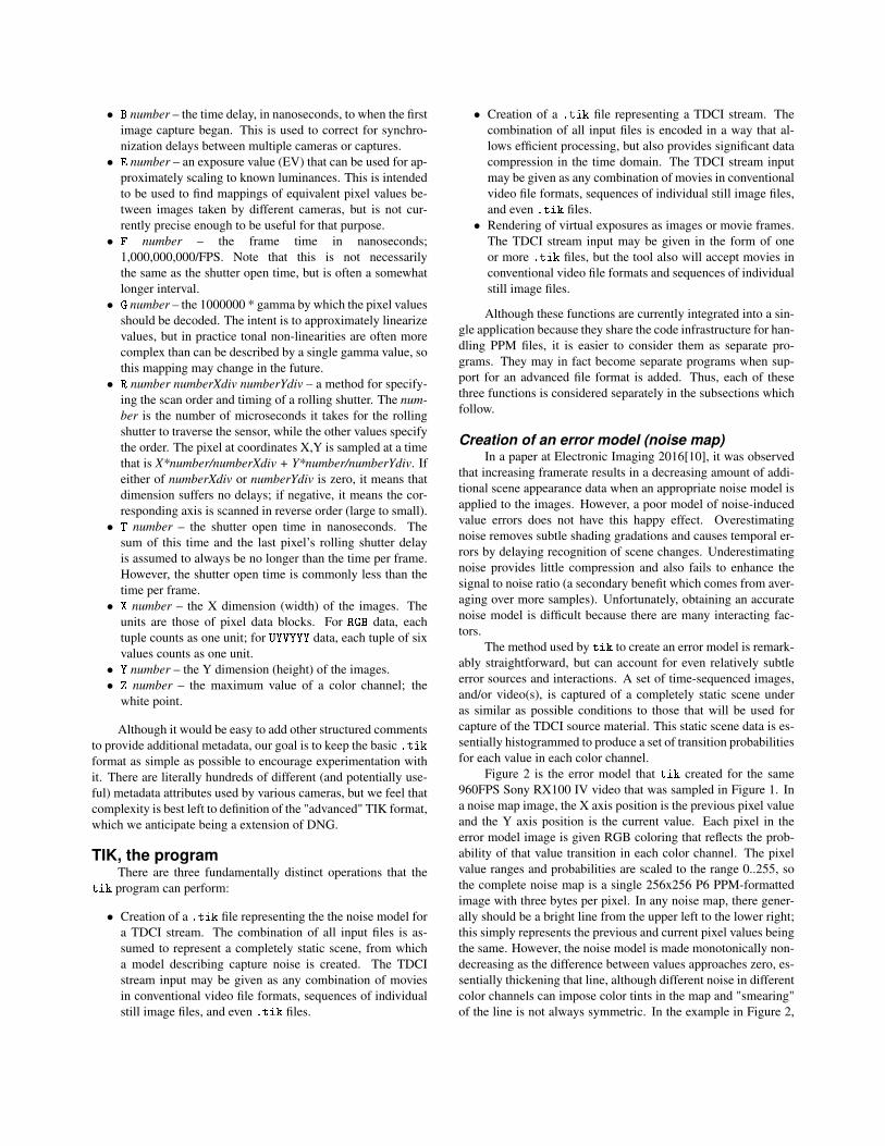
Figure 2 is the error model that tik created for the same960FPS Sony RX100 IV video that was sampled in Figure 1. Ina noise map image, the X axis position is the previous pixel valueand the Y axis position is the current value. Each pixel in theerror model image is given RGB coloring that reflects the prob-ability of that value transition in each color channel. The pixelvalue ranges and probabilities are scaled to the range 0..255, sothe complete noise map is a single 256x256 P6 PPM-formattedimage with three bytes per pixel. In any noise map, there gener-ally should be a bright line from the upper left to the lower right;this simply represents the previous and current pixel values beingthe same. However, the noise model is made monotonically non-decreasing as the difference between values approaches zero, es-sentially thickening that line, although different noise in differentcolor channels can impose color tints in the map and "smearing"of the line is not always symmetric. In the example in Figure 2,
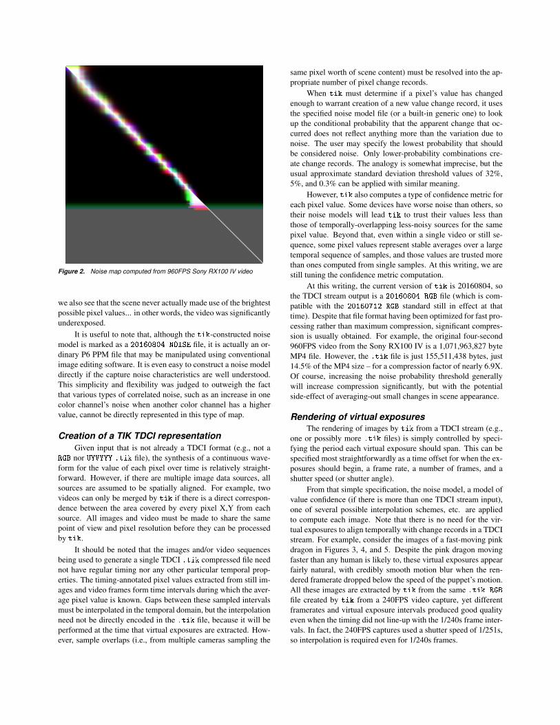
Figure 2. Noise map computed from 960FPS Sony RX100 IV video
we also see that the scene never actually made use of the brightestpossible pixel values... in other words, the video was significantlyunderexposed.
It is useful to note that, although the tik-constructed noisemodel is marked as a 20160804 NOISE file, it is actually an or-dinary P6 PPM file that may be manipulated using conventionalimage editing software. It is even easy to construct a noise modeldirectly if the capture noise characteristics are well understood.This simplicity and flexibility was judged to outweigh the factthat various types of correlated noise, such as an increase in onecolor channel’s noise when another color channel has a highervalue, cannot be directly represented in this type of map.
Creation of a TIK TDCI representationGiven input that is not already a TDCI format (e.g., not a
RGB nor UYVYYY .tik file), the synthesis of a continuous wave-form for the value of each pixel over time is relatively straight-forward. However, if there are multiple image data sources, allsources are assumed to be spatially aligned. For example, twovideos can only be merged by tik if there is a direct correspon-dence between the area covered by every pixel X,Y from eachsource. All images and video must be made to share the samepoint of view and pixel resolution before they can be processedby tik.
It should be noted that the images and/or video sequencesbeing used to generate a single TDCI .tik compressed file neednot have regular timing nor any other particular temporal prop-erties. The timing-annotated pixel values extracted from still im-ages and video frames form time intervals during which the aver-age pixel value is known. Gaps between these sampled intervalsmust be interpolated in the temporal domain, but the interpolationneed not be directly encoded in the .tik file, because it will beperformed at the time that virtual exposures are extracted. How-ever, sample overlaps (i.e., from multiple cameras sampling the
same pixel worth of scene content) must be resolved into the ap-propriate number of pixel change records.
When tik must determine if a pixel’s value has changedenough to warrant creation of a new value change record, it usesthe specified noise model file (or a built-in generic one) to lookup the conditional probability that the apparent change that oc-curred does not reflect anything more than the variation due tonoise. The user may specify the lowest probability that shouldbe considered noise. Only lower-probability combinations cre-ate change records. The analogy is somewhat imprecise, but theusual approximate standard deviation threshold values of 32%,5%, and 0.3% can be applied with similar meaning.
However, tik also computes a type of confidence metric foreach pixel value. Some devices have worse noise than others, sotheir noise models will lead tik to trust their values less thanthose of temporally-overlapping less-noisy sources for the samepixel value. Beyond that, even within a single video or still se-quence, some pixel values represent stable averages over a largetemporal sequence of samples, and those values are trusted morethan ones computed from single samples. At this writing, we arestill tuning the confidence metric computation.
At this writing, the current version of tik is 20160804, sothe TDCI stream output is a 20160804 RGB file (which is com-patible with the 20160712 RGB standard still in effect at thattime). Despite that file format having been optimized for fast pro-cessing rather than maximum compression, significant compres-sion is usually obtained. For example, the original four-second960FPS video from the Sony RX100 IV is a 1,071,963,827 byteMP4 file. However, the .tik file is just 155,511,438 bytes, just14.5% of the MP4 size – for a compression factor of nearly 6.9X.Of course, increasing the noise probability threshold generallywill increase compression significantly, but with the potentialside-effect of averaging-out small changes in scene appearance.
Rendering of virtual exposuresThe rendering of images by tik from a TDCI stream (e.g.,
one or possibly more .tik files) is simply controlled by speci-fying the period each virtual exposure should span. This can bespecified most straightforwardly as a time offset for when the ex-posures should begin, a frame rate, a number of frames, and ashutter speed (or shutter angle).
From that simple specification, the noise model, a model ofvalue confidence (if there is more than one TDCI stream input),one of several possible interpolation schemes, etc. are appliedto compute each image. Note that there is no need for the vir-tual exposures to align temporally with change records in a TDCIstream. For example, consider the images of a fast-moving pinkdragon in Figures 3, 4, and 5. Despite the pink dragon movingfaster than any human is likely to, these virtual exposures appearfairly natural, with credibly smooth motion blur when the ren-dered framerate dropped below the speed of the puppet’s motion.All these images are extracted by tik from the same .tik RGB
file created by tik from a 240FPS video capture, yet differentframerates and virtual exposure intervals produced good qualityeven when the timing did not line-up with the 1/240s frame inter-vals. In fact, the 240FPS captures used a shutter speed of 1/251s,so interpolation is required even for 1/240s frames.
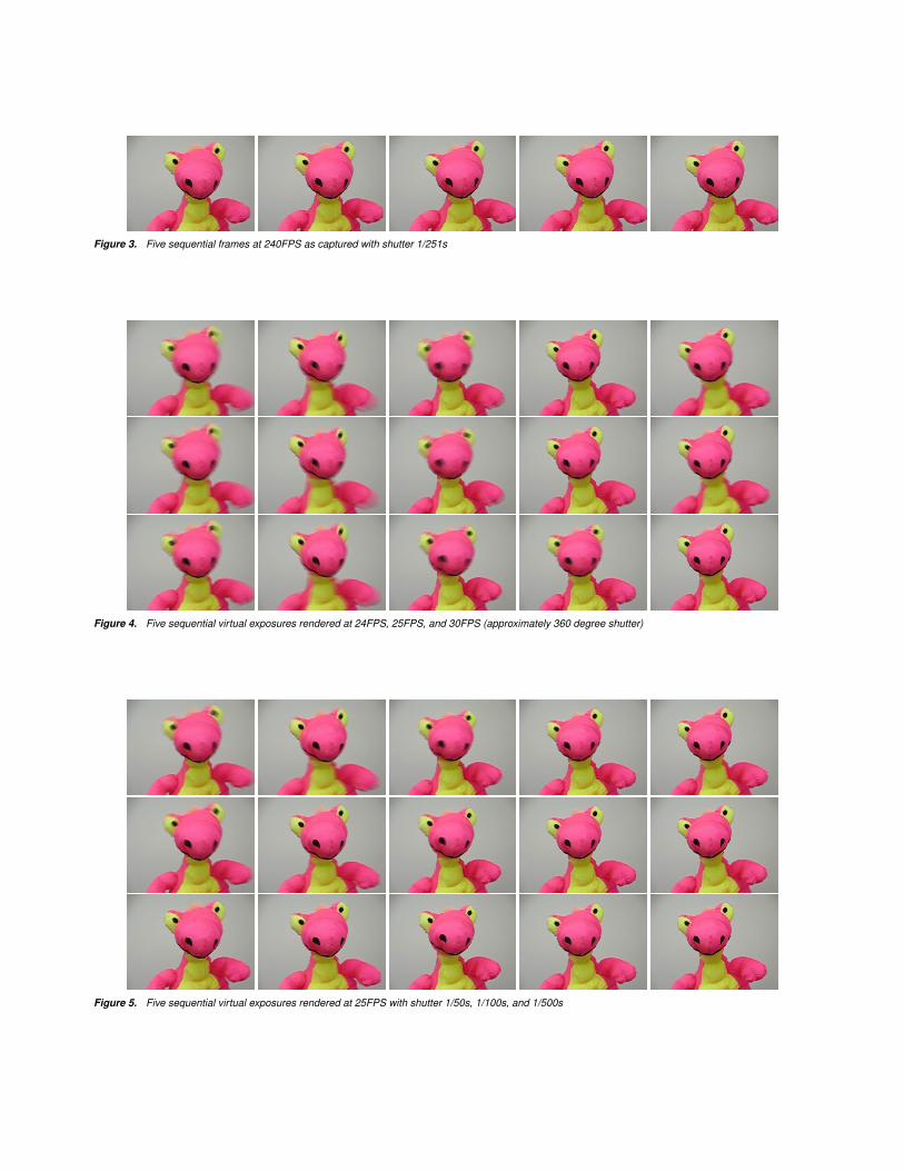
Figure 3. Five sequential frames at 240FPS as captured with shutter 1/251s
Figure 4. Five sequential virtual exposures rendered at 24FPS, 25FPS, and 30FPS (approximately 360 degree shutter)
Figure 5. Five sequential virtual exposures rendered at 25FPS with shutter 1/50s, 1/100s, and 1/500s

In general, if a TDCI stream is to be created from a sin-gle conventional video, there will be temporal gaps between theframes. These gaps might even be large; for example, a 24FPSvideo shot in bright daylight might use a shutter speed of 1/500s(i.e., a shutter angle of 17 degrees), meaning that less than 5% ofthe video’s elapsed time is sensed at all. These gaps, if presentin the TDCI stream, are currently interpolated by assuming thatthe value of a pixel linearly changes between adjacent temporalsamples. Although better interpolation schemes are being inves-tigated, linear interpolation in the time domain produces surpris-ingly good results when the sampling frequency is relatively high(i.e., when the original video capture was made at a frameratethat is fast compared to the rate of scene change). For tempo-ral sampling far below a Nyquist sampling of the scene change,such as the 24FPS 1/500s example mentioned earlier is likely tobe, linear temporal interpolation is not sufficient to produce goodquality; more sophisticated spatio-temporal interpolation wouldbe necessary, and even that might prove insufficient.
The computation of the virtual exposure pixel values is donein an approximately linear gamma space using double-precisionfloating-point values. Because many pixel values are often av-eraged over many samples or otherwise smoothly interpolated(as constrained by a noise model), signal to noise ratio and ef-fective dynamic range can both be much better than the originalcaptures would suggest. Thus, the resulting virtual exposure isreally a high dynamic range (HDR) image. Although we maylater output virtual exposures as HDR images, currently, they arestraightforwardly mapped into the dynamic range of the outputfile format.
Despite the various approximations made by tik, perhapsthe most surprising aspect of TDCI virtual exposure rendering isthat a virtual exposure will generally have better signal-to-noiseratio than the actual exposure representing the same time inter-val. This is the effect discussed earlier in the paper and shown inFigure 1.
ConclusionThis paper is intended to serve both to report preliminary
experimental test results for how well TDCI concepts can be ap-plied to conventionally-captured images and to invite to othersto use, experiment with, and contribute improvements to the tiktool and .tik file format. The full source code for the systemwill be openly available from aggregate.org.
There are some examples and performance analysis in thispaper, but we also intended to give live demonstrations of tik atElectronic Imaging 2017.
AcknowledgmentsThis work is supported in part under NSF Award #1422811,
CSR: Small: Computational Support for Time Domain Continu-ous Imaging.
References[1] Henry Gordon Dietz, Frameless, time domain continuous image cap-
ture, Proc. SPIE 9022, Image Sensors and Imaging Systems 2014,902207 (March 4, 2014); doi:10.1117/12.2040016. (2014).
[2] Richard L. White1, David J. Helfand2, Robert H. Becker, Eilat Glik-man, and Wim de Vries, Signals from the Noise: Image Stackingfor Quasars in the FIRST Survey, The Astrophysical Journal, Vol-ume 654, Number 1; http://stacks.iop.org/0004-637X/654/i=1/a=99(2007).
[3] Henry Gordon Dietz, Frameless representation and manipula-tion of image data, Proc. SPIE 9410, Visual Information Pro-cessing and Communication VI, 94100R (March 4, 2015);doi:10.1117/12.2083468. (2015).
[4] Deep Sky Stacker, http://deepskystacker.free.fr/ (accessed November26, 2016).
[5] Doug Kerr, APEX - The Additive System of Pho-tographic Exposure, Issue 7 (August 4, 2007);http://dougkerr.net/Pumpkin/index.htm#APEX (accessed November26, 2016).
[6] Adobe Systems Incorporated, Digital Negative (DNG) Specification,Version 1.4.0.0; http://www.adobe.com/ (June 2012).
[7] Jef Poskanzer, NETPBM: Extended portable bitmap toolkit, (1993).[8] Dave Coffin, Decoding raw digital photos in Linux,
http://www.cybercom.net/d̃coffin/dcraw/ (2016).[9] Canon Hack Development Kit (CHDK),
http://chdk.wikia.com/wiki/CHDK (accessed November 26, 2016).[10] Henry Gordon Dietz, Zachary Snyder, John Fike, and Pablo
Quevedo, Scene appearance change as framerate approaches infin-ity, Electronic Imaging, Digital Photography and Mobile ImagingXII, pp. 1-7 (February 14, 2016); (2016).
Author BiographyHenry (Hank) Dietz is a Professor in the Electrical and Com-
puter Engineering Department of the University of Kentucky. He andthe student co-authors of this paper, Paul Eberhart, John Fike, KatieLong, Clark Demaree, and Jong Wu, have been working to makeTime Domain Continuous Image capture and processing practical. SeeAggregate.Org for more information about their research on TDCIand a wide range of computer engineering topics.