Embed Size (px)
Citation preview
TIFFRevision 6.0Final — June 3, 1992
™
Adobe Developers Association
Adobe Systems Incorporated1585 Charleston RoadP.O. Box 7900Mountain View, CA 94039-7900
E-Mail: [email protected]
A copy of this specification can be found in
http://www.adobe.com/Support/TechNotes.html
and
ftp://ftp.adobe.com/pub/adobe/DeveloperSupport/TechNotes/PDFfiles
TIFF 6.0 Specification Final—June 3, 1992
2
Copyright© 1986-1988, 1992 by Adobe Systems Incorporated. Permission to copy withoutfee all or part of this material is granted provided that the copies are not made ordistributed for direct commercial advantage and the Adobe copyright notice ap-pears. If the majority of the document is copied or redistributed, it must be distrib-uted verbatim, without repagination or reformatting. To copy otherwise requiresspecific permission from the Adobe Systems Incorporated.
Licenses and TrademarksPostScript is a trademark of Adobe Systems Incorporated. All instances of thename PostScript in the text are references to the PostScript language as defined byAdobe Systems Incorporated unless otherwise stated. The name PostScript also isused as a product trademark for Adobe Systems’ implementation of the PostScriptlanguage interpreter.
Any references to a “PostScript printer,” a “PostScript file,” or a “PostScriptdriver” refer to printers, files, and driver programs (respectively) which are writ-ten in or support the PostScript language. The sentences in this specification thatuse “PostScript language” as an adjective phrase are so constructed to reinforcethat the name refers to the standard language definition as set forth by AdobeSystems Incorporated.
PostScript, the PostScript logo, Display PostScript, Adobe, the Adobe logo,Adobe Illustrator, Aldus, PageMaker, TIFF, OPI, TrapWise, Tran-Script, Carta,and Sonata are trademarks of Adobe Systems Incorporated or its subsidiaries, andmay be registered in some jurisdictions.
Apple, LaserWriter, and Macintosh are registered trademarks and Finder andSystem 7 are trademarks of Apple, Computer, Inc. Microsoft and MS-DOS areregistered trademarks and Windows is a trademark of Microsoft Corporation.UNIX is a registered trademark of UNIX System Laboratories, Inc., a whollyowned subsidiary of Novell, Inc. All other trademarks are the property of theirrespective owners.
Production NotesThis document was created electronically using Adobe PageMaker® 6.0.
TIFF 6.0 Specification Final—June 3, 1992
3
Contents
Introduction ....................................................................................................................4About this Specification ...................................................................... 4
Revision Notes .....................................................................................6
TIFF Administration .............................................................................8Information and Support .........................................................................8Private Fields and Values ...................................................................... 8Submitting a Proposal ............................................................................9The TIFF Advisory Committee ............................................................... 9Other TIFF Extensions ...........................................................................9
Part 1: Baseline TIFF....................................................................................................11Section 1: Notation ............................................................................12
Section 2: TIFF Structure ..................................................................13
Section 3: Bilevel Images ..................................................................17
Section 4: Grayscale Images ............................................................22
Section 5: Palette-color Images ........................................................ 23
Section 6: RGB Full Color Images .................................................... 24
Section 7: Additional Baseline TIFF Requirements ........................ 26
Section 8: Baseline Field Reference Guide .....................................28
Section 9: PackBits Compression .................................................... 42
Section 10: Modified Huffman Compression ...................................43
Part 2: TIFF Extensions ..............................................................................................48Section 11: CCITT Bilevel Encodings ..............................................49
Section 12: Document Storage and Retrieval ................................. 55
Section 13: LZW Compression .........................................................57
Section 14: Differencing Predictor ...................................................64
Section 15: Tiled Images ...................................................................66
Section 16: CMYK Images ................................................................. 69
Section 17: HalftoneHints ..................................................................72
Section 18: Associated Alpha Handling ..........................................77
Section 19: Data Sample Format ...................................................... 80
Section 20: RGB Image Colorimetry ................................................82
Section 21: YCbCr Images ................................................................89
Section 22: JPEG Compression .......................................................95
Section 23: CIE L*a*b* Images ........................................................ 110
Part 3: Appendices ....................................................................................................116Appendix A: TIFF Tags Sorted by Number .................................... 117
Appendix B: Operating System Considerations ........................... 119Index ...............................................................................120
TIFF 6.0 Specification Final—June 3, 1992
ang-
n inrs and la-
rilr
ers,
TIFF
of the
ppli-
highbe
Introduction
About this Specification
This document describes TIFF, a tag-based file format for storing and interching raster images.
History
The first version of the TIFF specification was published by Aldus Corporatiothe fall of 1986, after a series of meetings with various scanner manufacturesoftware developers. It did not have a revision number but should have beenbeled Revision 3.0 since there were two major earlier draft releases.
Revision 4.0 contained mostly minor enhancements and was released in Ap1987. Revision 5.0, released in October 1988, added support for palette coloimages and LZW compression.
Scope
TIFF describes image data that typically comes from scanners, frame grabband paint- and photo-retouching programs.
TIFF is not a printer language or page description language. The purpose ofis to describe and store raster image data.
A primary goal of TIFF is to provide a rich environment within which applica-tions can exchange image data. This richness is required to take advantagevarying capabilities of scanners and other imaging devices.
Though TIFF is a rich format, it can easily be used for simple scanners and acations as well because the number of required fields is small.
TIFF will be enhanced on a continuing basis as new imaging needs arise. A priority has been given to structuring TIFF so that future enhancements can added without causing unnecessary hardship to developers.
4
TIFF 6.0 Specification Final—June 3, 1992
or
re.
s,
e.
ose
Features
• TIFF is capable of describing bilevel, grayscale, palette-color, and full-colimage data in several color spaces.
• TIFF includes a number of compression schemes that allow developers tochoose the best space or time tradeoff for their applications.
• TIFF is not tied to specific scanners, printers, or computer display hardwa
• TIFF is portable. It does not favor particular operating systems, file systemcompilers, or processors.
• TIFF is designed to be extensible—to evolve gracefully as new needs aris
• TIFF allows the inclusion of an unlimited amount of private or special-purpinformation.
5

TIFF 6.0 Specification Final—June 3, 1992
or-
3,
lly-
od-
de-
asre
Revision Notes
Minor changes to TIFF 6.0, March 1995
Updated contact information and TIFF administration policies, since Aldus Cporation merged with Adobe Systems Incorporated on September 1, 1994.
The technical content and pagination are unchanged from the original June 1992 release.
TIFF 5.0 to TIFF 6.0
This revision replaces TIFF Revision 5.0.
In the main body of the document, paragraphs that contain new or substantiachanged information are shown in italics.
New Features in Revision 6.0
Major enhancements to TIFF 6.0 are described in Part 2. They include:
• CMYK image definition
• A revised RGB Colorimetry section.
• YCbCr image definition
• CIE L*a*b* image definition
• Tiled image definition
• JPEG compression
Clarifications
• The LZW compression section more clearly explains when to switch the cing bit length.
• The interaction between Compression=2 (CCITT Huffman) andPhotometricInterpretation was clarified.
• The data organization of uncompressed data (Compression=1) whenBitsPerSample is greater than 8 was clarified. See the Compression field scription.
• The discussion of CCITT Group 3 and Group 4 bilevel image encodings wclarified and expanded, and Group3Options and Group4Options fields werenamed T4Options and T6Options. See Section 11.
6

TIFF 6.0 Specification Final—June 3, 1992
ere
helprt 1,FFer of
odygynteline
“Part
ak-
enti-g”
,
izesionsso-anead- the
newoft-e to.
Organizational Changes
• To make the organization more consistent and expandable, appendices wtransformed into numbered sections.
• The document was divided into two parts—Baseline and Extensions—to developers make better and more consistent implementation choices. Pathe Baseline section, describes those features that all general-purpose TIreaders should support. Part 2, the Extensions section, describes a numbfeatures that can be used by special or advanced applications.
• An index and table of contents were added.
Changes in Requirements
• To illustrate a Baseline TIFF file earlier in the document, the material fromAppendix G (“TIFF Classes”) in Revision 5 was integrated into the main bof the specification . As part of this integration, the TIFF Classes terminolowas replaced by the more monolithic Baseline TIFF terminology. The intewas to further encourage all mainstream TIFF readers to support the BasTIFF requirements for bilevel, grayscale, RGB, and palette-color images.
• Due to licensing issues, LZW compression support was moved out of the1: Baseline TIFF” and into “Part 2: Extensions.”
• Baseline TIFF requirements for bit depths in palette-color images were weened a bit.
Changes in Terminology
In previous versions of the specification, the term “tag” reffered both to the idfying number of a TIFF field and to the entire field. In this version, the term “tarefers only to the identifying number. The term “field” refers to the entire fieldincluding the value.
Compatibility
Every attempt has been made to add functionality in such a way as to minimcompatibility problems with files and software that were based on earlier verof the TIFF specification. The goal is that TIFF files should never become oblete and that TIFF software should not have to be revised more frequently thabsolutely necessary. In particular, Baseline TIFF 6.0 files will generally be rable even by older applications that assume TIFF 5.0 or an earlier version ofspecification.
However, TIFF 6.0 files that use one of the major new extensions, such as acompression scheme or color space, will not be successfully read by older sware. In such cases, the older applications must gracefully give up and refusimport the image, providing the user with a reasonably informative message
7
TIFF 6.0 Specification Final—June 3, 1992
onthe
un-el-
you.
mse.com.
inrt
i-ate
.com)idd-helpag
x-TIFF.sage.rated
ms
tibilityfiles
g
TIFF Administration
Information and Support
The most recent version of the TIFF specification is available in PDF format the Adobe WWW and ftp servers See the cover page of the specification for required addresses.
Because of the widespread use of TIFF for in many environments, Adobe is able to provide a general consulting service for TIFF implementors. TIFF devopers are encouraged to study sample TIFF files, read TIFF documentationthoroughly, and work with developers of other products that are important to
If your TIFF question specifically concerns compatibility with an Adobe Systeproduct, please contact Adobe Developer Support at devsup-person@adob
Most companies that use TIFF can answer questions about support for TIFFtheir products. Contact the appropriate product manager or developer supposervice group.
Private Fields and Values
An organization might wish to store information meaningful to only that organzation in a TIFF file. Tags numbered 32768 or higher, sometimes called privtags, are reserved for that purpose.
Upon request, the TIFF administrator (send email to devsup-person@adobewill allocate and register one or more private tags for an organization, to avopossible conflicts with other organizations. You do not need to tell the TIFF aministrator what you plan to use them for, but giving us this information may other developers to avoid some duplication of effort. We will likely make the tdatabase public at some point.
Private enumerated values can be accommodated in a similar fashion. For eample, you may wish to experiment with a new compression scheme within Enumeration constants numbered 32768 or higher are reserved for private uUpon request, the administrator will allocate and register one or more enumevalues for a particular field (Compression, in our example), to avoid possibleconflicts.
Tags and values allocated in the private number range are not prohibited frobeing included in a future revision of this specification. Several such instanceexist in the current TIFF specification.
Do not choose your own tag numbers. Doing so could cause serious compaproblems in the future. However, if there is little or no chance that your TIFF will escape your private environment, please consider using TIFF tags in the“reusable” 65000-65535 range. You do not need to contact Adobe when usinnumbers in this range.
8

TIFF 6.0 Specification Final—June 3, 1992
tag,a useou
speci-
ion.s of
ber to TIFF
histheestship,en
rpa-
en-or-m in
If you need more than 10 tags, we suggest that you reserve a single private define it as a LONG TIFF data type, and use its value as a pointer (offset) to private IFD or other data structure of your choosing. Within that IFD, you canwhatever tags you want, since no one else will know that it is an IFD unless ytell them.
Submitting a Proposal
Any person or group that wants to propose a change or addition to the TIFF fication should prepare a proposal that includes the following information:
• Name of the person or group making the request, and your affiliation.
• The reason for the request.
• A list of changes exactly as you propose that they appear in the specificatUse inserts, callouts, or other obvious editorial techniques to indicate areachange, and number each change.
• Discussion of the potential impact on the installed base.
• A list of contacts outside your company that support your position. Includetheir affiliation.
Please send your proposal to [email protected].
The TIFF Advisory Committee
The TIFF Advisory Committee is a working group of TIFF experts from a numof hardware and software manufacturers. It was formed in the spring of 1991provide a forum for debating and refining proposals for the 6.0 release of thespecification.
If you are a TIFF expert and think you have the time and interest to work on tcommittee, contact [email protected] for further information. For TIFF 6.0 release, the group met every two or three months, usually on the wcoast of the U.S. Accessibility via Internet email is a requirement for membersince that has proven to be an invaluable means for getting work done betwemeetings.
Other TIFF Extensions
The Aldus TIFF sections on CompuServe and AppleLink (new location is underconstruction; check the Adobe WWW home page (http://www.adobe.com) fofuture developements) will contain proposed TIFF extensions from other comnies that are not approved by Adobe as part of Baseline TIFF.
These proposals typically represent specialized uses of TIFF that do not fallwithin the domain of publishing or general graphics or picture interchange. Gerally, these features will not be widely supported. If you do write files that incporate these extensions, be sure to either not call them TIFF files or mark thesome way so that they will not be confused with mainstream TIFF files.
9

TIFF 6.0 Specification Final—June 3, 1992
mis-rma-
If you have such a document, send it to [email protected]. All subsions must be PDF documents or simple text. Be sure to include contact infotion—at least an email address.
10
TIFF 6.0 Specification Final—June 3, 1992
vel-
Part 1: Baseline TIFFThe TIFF specification is divided into two parts. Part 1 describes Baseline TIFF.Baseline TIFF is the core of TIFF, the essentials that all mainstream TIFF deopers should support in their products.
11
TIFF 6.0 Specification Final—June 3, 1992
n
rs
nsid-nated-s.
Section 1: Notation
Decimal and Hexadecimal
Unless otherwise noted, all numeric values in this document are expressed idecimal. (“.H” is appended to hexidecimal values.)
Compliance
Is and shall indicate mandatory requirements. All compliant writers and reademust meet the specification.
Should indicates a recommendation.
May indicates an option.
Features designated ‘not recommended for general data interchange’ are coered extensions to Baseline TIFF. Files that use such features shall be desig“Extended TIFF 6.0” files, and the particular extensions used should be documented. A Baseline TIFF 6.0 reader is not required to support any extension
12
TIFF 6.0 Specification Final—June 3, 1992
ofTIFF
as
tail.
st
s a
the
e
t of
Section 2: TIFF Structure
TIFF is an image file format. In this document, a file is defined to be a sequence 8-bit bytes, where the bytes are numbered from 0 to N. The largest possible file is 2**32 bytes in length.
A TIFF file begins with an 8-byte image file header that points to an image filedirectory (IFD). An image file directory contains information about the image,well as pointers to the actual image data.
The following paragraphs describe the image file header and IFD in more de
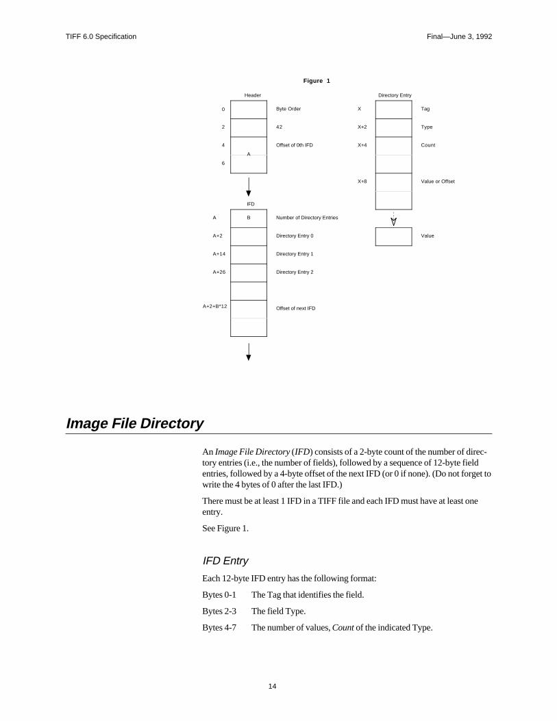
See Figure 1.
Image File Header
A TIFF file begins with an 8-byte image file header, containing the followinginformation:
Bytes 0-1: The byte order used within the file. Legal values are:
“II” (4949.H)
“MM” (4D4D.H)
In the “II” format, byte order is always from the least significant byte to the mosignificant byte, for both 16-bit and 32-bit integers This is called little-endian byteorder. In the “MM” format, byte order is always from most significant to leastsignificant, for both 16-bit and 32-bit integers. This is called big-endian byteorder.
Bytes 2-3 An arbitrary but carefully chosen number (42) that further identifies the file aTIFF file.
The byte order depends on the value of Bytes 0-1.
Bytes 4-7 The offset (in bytes) of the first IFD. The directory may be at any location in file after the header but must begin on a word boundary. In particular, an ImageFile Directory may follow the image data it describes. Readers must follow thpointers wherever they may lead.
The term byte offset is always used in this document to refer to a location withrespect to the beginning of the TIFF file. The first byte of the file has an offse0.
13
TIFF 6.0 Specification Final—June 3, 1992
c-ldet to
ne
0
2
4
6
Byte Order
42
Offset of 0th IFD
Figure 1
Header
A
A
A+2
A+14
A+26
A+2+B*12
B Number of Directory Entries
Directory Entry 0
Directory Entry 1
Directory Entry 2
Offset of next IFD
IFD
X
X+2
X+4
X+8
Tag
Type
Count
Value or Offset
Directory Entry
Value
Image File Directory
An Image File Directory (IFD) consists of a 2-byte count of the number of diretory entries (i.e., the number of fields), followed by a sequence of 12-byte fieentries, followed by a 4-byte offset of the next IFD (or 0 if none). (Do not forgwrite the 4 bytes of 0 after the last IFD.)
There must be at least 1 IFD in a TIFF file and each IFD must have at least oentry.
See Figure 1.
IFD Entry
Each 12-byte IFD entry has the following format:
Bytes 0-1 The Tag that identifies the field.
Bytes 2-3 The field Type.
Bytes 4-7 The number of values, Count of the indicated Type.
14
TIFF 6.0 Specification Final—June 3, 1992
ld.ond-y
l
is isto
ing to
-ype
ofle 16-
te
ingnitial
Bytes 8-11 The Value Offset, the file offset (in bytes) of the Value for the fieThe Value is expected to begin on a word boundary; the corresping Value Offset will thus be an even number. This file offset mapoint anywhere in the file, even after the image data.
IFD Terminology
A TIFF field is a logical entity consisting of TIFF tag and its value. This logicaconcept is implemented as an IFD Entry, plus the actual value if it doesn’t fit intothe value/offset part, the last 4 bytes of the IFD Entry. The terms TIFF field andIFD entry are interchangeable in most contexts.
Sort Order
The entries in an IFD must be sorted in ascending order by Tag. Note that thnot the order in which the fields are described in this document. The Values which directory entries point need not be in any particular order in the file.
Value/Offset
To save time and space the Value Offset contains the Value instead of pointthe Value if and only if the Value fits into 4 bytes. If the Value is shorter than 4bytes, it is left-justified within the 4-byte Value Offset, i.e., stored in the lowernumbered bytes. Whether the Value fits within 4 bytes is determined by the Tand Count of the field.
Count
Count—called Length in previous versions of the specification—is the numbervalues. Note that Count is not the total number of bytes. For example, a singbit word (SHORT) has a Count of 1; not 2.
Types
The field types and their sizes are:
1 = BYTE 8-bit unsigned integer.
2 = ASCII 8-bit byte that contains a 7-bit ASCII code; the last bymust be NUL (binary zero).
3 = SHORT 16-bit (2-byte) unsigned integer.
4 = LONG 32-bit (4-byte) unsigned integer.
5 = RATIONAL Two LONGs: the first represents the numerator of afraction; the second, the denominator.
The value of the Count part of an ASCII field entry includes the NUL. If paddis necessary, the Count does not include the pad byte. Note that there is no i“count byte” as in Pascal-style strings.
15

TIFF 6.0 Specification Final—June 3, 1992
is
the
IFFidth
with
edkes
n
a
IFF
ally.
ed to
fac-
Any ASCII field can contain multiple strings, each terminated with a NUL. Asingle string is preferred whenever possible. The Count for multi-string fieldsthe number of bytes in all the strings in that field plus their terminating NULbytes. Only one NUL is allowed between strings, so that the strings followingfirst string will often begin on an odd byte.
The reader must check the type to verify that it contains an expected value. Tcurrently allows more than 1 valid type for some fields. For example, ImageWand ImageLength are usually specified as having type SHORT. But images more than 64K rows or columns must use the LONG field type.
TIFF readers should accept BYTE, SHORT, or LONG values for any unsigninteger field. This allows a single procedure to retrieve any integer value, mareading more robust, and saves disk space in some situations.
In TIFF 6.0, some new field types have been defined:
6 = SBYTE An 8-bit signed (twos-complement) integer.
7 = UNDEFINED An 8-bit byte that may contain anything, depending othe definition of the field.
8 = SSHORT A 16-bit (2-byte) signed (twos-complement) integer.
9 = SLONG A 32-bit (4-byte) signed (twos-complement) integer.
10 = SRATIONAL Two SLONG’s: the first represents the numerator of fraction, the second the denominator.
11 = FLOAT Single precision (4-byte) IEEE format.
12 = DOUBLE Double precision (8-byte) IEEE format.
These new field types are also governed by the byte order (II or MM) in the Theader.
Warning: It is possible that other TIFF field types will be added in the future.Readers should skip over fields containing an unexpected field type.
Fields are arrays
Each TIFF field has an associated Count. This means that all fields are actuone-dimensional arrays, even though most fields contain only a single value
For example, to store a complicated data structure in a single private field, usthe UNDEFINED field type and set the Count to the number of bytes requirehold the data structure.
Multiple Images per TIFF File
There may be more than one IFD in a TIFF file. Each IFD defines a subfile. Onepotential use of subfiles is to describe related images, such as the pages of asimile transmission. A Baseline TIFF reader is not required to read any IFDsbeyond the first one.
16
TIFF 6.0 Specification Final—June 3, 1992
fillingata.
four-
fly
a-he
axi-
axi-he
nuseday of
Section 3: Bilevel Images
Now that the overall TIFF structure has been described, we can move on to the structure with actual fields (tags and values) that describe raster image d
To make all of this clearer, the discussion will be organized according to the Baseline TIFF image types: bilevel, grayscale, palette-color, and full-color images. This section describes bilevel images.
Fields required to describe bilevel images are introduced and described briehere. Full descriptions of each field can be found in Section 8.
Color
A bilevel image contains two colors—black and white. TIFF allows an appliction to write out bilevel data in either a white-is-zero or black-is-zero format. Tfield that records this information is called PhotometricInterpretation.
PhotometricInterpretationTag = 262 (106.H)
Type = SHORT
Values:
0 = WhiteIsZero. For bilevel and grayscale images: 0 is imaged as white. The mmum value is imaged as black. This is the normal value for Compression=2.
1 = BlackIsZero. For bilevel and grayscale images: 0 is imaged as black. The mmum value is imaged as white. If this value is specified for Compression=2, timage should display and print reversed.
Compression
Data can be stored either compressed or uncompressed.
CompressionTag = 259 (103.H)
Type = SHORT
Values:
1 = No compression, but pack data into bytes as tightly as possible, leaving no ubits (except at the end of a row). The component values are stored as an arrtype BYTE. Each scan line (row) is padded to the next BYTE boundary.
2 = CCITT Group 3 1-Dimensional Modified Huffman run length encoding. See
17
TIFF 6.0 Specification Final—June 3, 1992
is
ge. the
uare
Section 10 for a description of Modified Huffman Compression.
32773 = PackBits compression, a simple byte-oriented run length scheme. See thePackBits section for details.
Data compression applies only to raster image data. All other TIFF fields areunaffected.
Baseline TIFF readers must handle all three compression schemes.
Rows and Columns
An image is organized as a rectangular array of pixels. The dimensions of tharray are stored in the following fields:
ImageLengthTag = 257 (101.H)
Type = SHORT or LONG
The number of rows (sometimes described as scanlines) in the image.
ImageWidthTag = 256 (100.H)
Type = SHORT or LONG
The number of columns in the image, i.e., the number of pixels per scanline.
Physical Dimensions
Applications often want to know the size of the picture represented by an imaThis information can be calculated from ImageWidth and ImageLength givenfollowing resolution data:
ResolutionUnitTag = 296 (128.H)
Type = SHORT
Values:
1 = No absolute unit of measurement. Used for images that may have a non-sqaspect ratio but no meaningful absolute dimensions.
2 = Inch.
3 = Centimeter.
Default = 2 (inch).
18
TIFF 6.0 Specification Final—June 3, 1992
ntal
al)
in aasedp is
they
XResolutionTag = 282 (11A.H)
Type = RATIONAL
The number of pixels per ResolutionUnit in the ImageWidth (typically, horizo- see Orientation) direction.
YResolutionTag = 283 (11B.H)
Type = RATIONAL
The number of pixels per ResolutionUnit in the ImageLength (typically, verticdirection.
Location of the Data
Compressed or uncompressed image data can be stored almost anywhere TIFF file. TIFF also supports breaking an image into separate strips for increediting flexibility and efficient I/O buffering. The location and size of each strigiven by the following fields:
RowsPerStripTag = 278 (116.H)
Type = SHORT or LONG
The number of rows in each strip (except possibly the last strip.)
For example, if ImageLength is 24, and RowsPerStrip is 10, then there are 3strips, with 10 rows in the first strip, 10 rows in the second strip, and 4 rows inthird strip. (The data in the last strip is not padded with 6 extra rows of dummdata.)
StripOffsetsTag = 273 (111.H)
Type = SHORT or LONG
For each strip, the byte offset of that strip.
StripByteCountsTag = 279 (117.H)
Type = SHORT or LONG
For each strip, the number of bytes in that strip after any compression.
19
TIFF 6.0 Specification Final—June 3, 1992
-
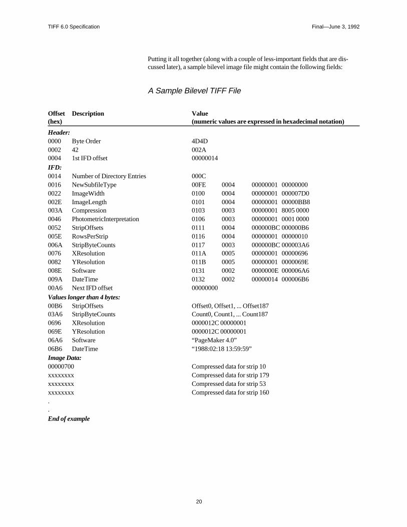
Putting it all together (along with a couple of less-important fields that are discussed later), a sample bilevel image file might contain the following fields:A Sample Bilevel TIFF File
Offset Description Value(hex) (numeric values are expressed in hexadecimal notation)
Header:0000 Byte Order 4D4D0002 42 002A0004 1st IFD offset 00000014
IFD:0014 Number of Directory Entries 000C0016 NewSubfileType 00FE 0004 00000001 000000000022 ImageWidth 0100 0004 00000001 000007D0002E ImageLength 0101 0004 00000001 00000BB8003A Compression 0103 0003 00000001 8005 00000046 PhotometricInterpretation 0106 0003 00000001 0001 00000052 StripOffsets 0111 0004 000000BC 000000B6005E RowsPerStrip 0116 0004 00000001 00000010006A StripByteCounts 0117 0003 000000BC 000003A60076 XResolution 011A 0005 00000001 000006960082 YResolution 011B 0005 00000001 0000069E008E Software 0131 0002 0000000E 000006A6009A DateTime 0132 0002 00000014 000006B600A6 Next IFD offset 00000000
Values longer than 4 bytes:00B6 StripOffsets Offset0, Offset1, ... Offset18703A6 StripByteCounts Count0, Count1, ... Count1870696 XResolution 0000012C 00000001069E YResolution 0000012C 0000000106A6 Software “PageMaker 4.0”06B6 DateTime “1988:02:18 13:59:59”Image Data:00000700 Compressed data for strip 10xxxxxxxx Compressed data for strip 179xxxxxxxx Compressed data for strip 53xxxxxxxx Compressed data for strip 160..
End of example
20
TIFF 6.0 Specification Final—June 3, 1992
e file the
aders tods be
ips ofrate
-
eioust were
3
sions
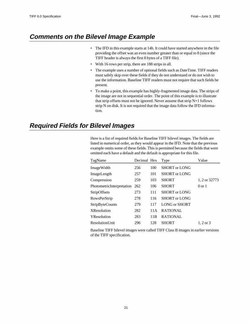
Comments on the Bilevel Image Example
• The IFD in this example starts at 14h. It could have started anywhere in thproviding the offset was an even number greater than or equal to 8 (sinceTIFF header is always the first 8 bytes of a TIFF file).
• With 16 rows per strip, there are 188 strips in all.
• The example uses a number of optional fields such as DateTime. TIFF remust safely skip over these fields if they do not understand or do not wishuse the information. Baseline TIFF readers must not require that such fielpresent.
• To make a point, this example has highly-fragmented image data. The strthe image are not in sequential order. The point of this example is to illustthat strip offsets must not be ignored. Never assume that strip N+1 followsstrip N on disk. It is not required that the image data follow the IFD information.
Required Fields for Bilevel Images
Here is a list of required fields for Baseline TIFF bilevel images. The fields arlisted in numerical order, as they would appear in the IFD. Note that the prevexample omits some of these fields. This is permitted because the fields thaomitted each have a default and the default is appropriate for this file.
TagName Decimal Hex Type Value
ImageWidth 256 100 SHORT or LONG
ImageLength 257 101 SHORT or LONG
Compression 259 103 SHORT 1, 2 or 3277
PhotometricInterpretation 262 106 SHORT 0 or 1
StripOffsets 273 111 SHORT or LONG
RowsPerStrip 278 116 SHORT or LONG
StripByteCounts 279 117 LONG or SHORT
XResolution 282 11A RATIONAL
YResolution 283 11B RATIONAL
ResolutionUnit 296 128 SHORT 1, 2 or 3
Baseline TIFF bilevel images were called TIFF Class B images in earlier verof the TIFF specification.
21
TIFF 6.0 Specification Final—June 3, 1992
stores of
ther
orithm.
anyed.
ver-
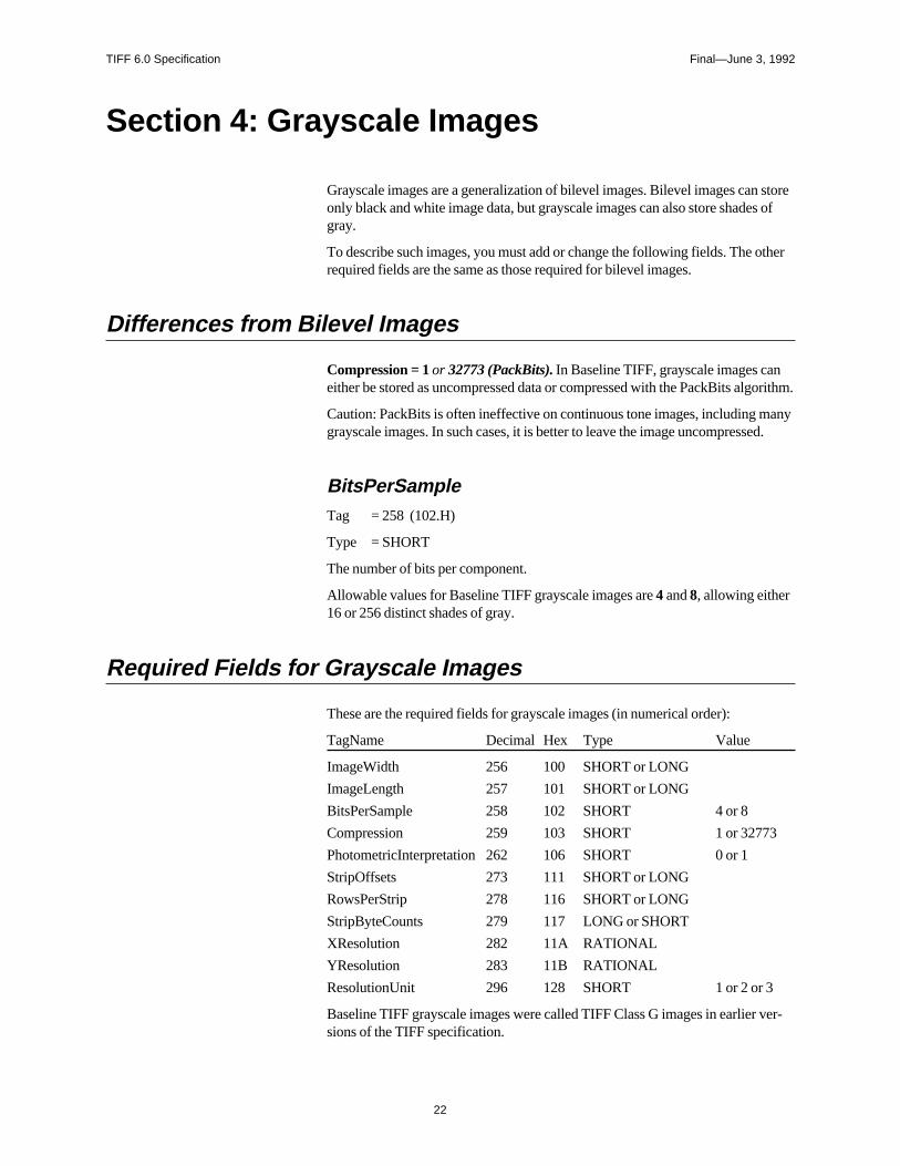
Section 4: Grayscale Images
Grayscale images are a generalization of bilevel images. Bilevel images canonly black and white image data, but grayscale images can also store shadegray.
To describe such images, you must add or change the following fields. The orequired fields are the same as those required for bilevel images.
Differences from Bilevel Images
Compression = 1 or 32773 (PackBits). In Baseline TIFF, grayscale images caneither be stored as uncompressed data or compressed with the PackBits alg
Caution: PackBits is often ineffective on continuous tone images, including mgrayscale images. In such cases, it is better to leave the image uncompress
BitsPerSampleTag = 258 (102.H)
Type = SHORT
The number of bits per component.
Allowable values for Baseline TIFF grayscale images are 4 and 8, allowing either16 or 256 distinct shades of gray.
Required Fields for Grayscale Images
These are the required fields for grayscale images (in numerical order):
TagName Decimal Hex Type Value
ImageWidth 256 100 SHORT or LONG
ImageLength 257 101 SHORT or LONG
BitsPerSample 258 102 SHORT 4 or 8
Compression 259 103 SHORT 1 or 32773
PhotometricInterpretation 262 106 SHORT 0 or 1
StripOffsets 273 111 SHORT or LONG
RowsPerStrip 278 116 SHORT or LONG
StripByteCounts 279 117 LONG or SHORT
XResolution 282 11A RATIONAL
YResolution 283 11B RATIONAL
ResolutionUnit 296 128 SHORT 1 or 2 or 3
Baseline TIFF grayscale images were called TIFF Class G images in earliersions of the TIFF specification.
22
TIFF 6.0 Specification Final—June 3, 1992
po-ookupds.
ornto anld
ues,ite is
er
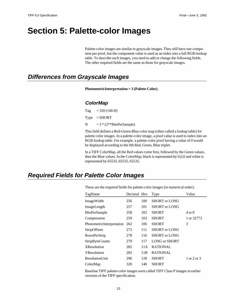
Section 5: Palette-color Images
Palette-color images are similar to grayscale images. They still have one comnent per pixel, but the component value is used as an index into a full RGB-ltable. To describe such images, you need to add or change the following fielThe other required fields are the same as those for grayscale images.
Differences from Grayscale Images
PhotometricInterpretation = 3 (Palette Color).
ColorMapTag = 320 (140.H)
Type = SHORT
N = 3 * (2**BitsPerSample)
This field defines a Red-Green-Blue color map (often called a lookup table) fpalette color images. In a palette-color image, a pixel value is used to index iRGB-lookup table. For example, a palette-color pixel having a value of 0 woube displayed according to the 0th Red, Green, Blue triplet.
In a TIFF ColorMap, all the Red values come first, followed by the Green valthen the Blue values. In the ColorMap, black is represented by 0,0,0 and whrepresented by 65535, 65535, 65535.
Required Fields for Palette Color Images
These are the required fields for palette-color images (in numerical order):
TagName Decimal Hex Type Value
ImageWidth 256 100 SHORT or LONG
ImageLength 257 101 SHORT or LONG
BitsPerSample 258 102 SHORT 4 or 8
Compression 259 103 SHORT 1 or 32773
PhotometricInterpretation 262 106 SHORT 3
StripOffsets 273 111 SHORT or LONG
RowsPerStrip 278 116 SHORT or LONG
StripByteCounts 279 117 LONG or SHORT
XResolution 282 11A RATIONAL
YResolution 283 11B RATIONAL
ResolutionUnit 296 128 SHORT 1 or 2 or 3
ColorMap 320 140 SHORT
Baseline TIFF palette-color images were called TIFF Class P images in earliversions of the TIFF specification.
23
TIFF 6.0 Specification Final—June 3, 1992
d
ndolor
B
essn.
Section 6: RGB Full Color Images
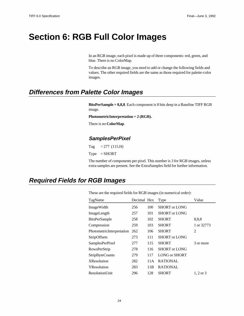
In an RGB image, each pixel is made up of three components: red, green, anblue. There is no ColorMap.
To describe an RGB image, you need to add or change the following fields avalues. The other required fields are the same as those required for palette-cimages.
Differences from Palette Color Images
BitsPerSample = 8,8,8. Each component is 8 bits deep in a Baseline TIFF RGimage.
PhotometricInterpretation = 2 (RGB).
There is no ColorMap .
SamplesPerPixelTag = 277 (115.H)
Type = SHORT
The number of components per pixel. This number is 3 for RGB images, unlextra samples are present. See the ExtraSamples field for further informatio
Required Fields for RGB Images
These are the required fields for RGB images (in numerical order):
TagName Decimal Hex Type Value
ImageWidth 256 100 SHORT or LONG
ImageLength 257 101 SHORT or LONG
BitsPerSample 258 102 SHORT 8,8,8
Compression 259 103 SHORT 1 or 32773
PhotometricInterpretation 262 106 SHORT 2
StripOffsets 273 111 SHORT or LONG
SamplesPerPixel 277 115 SHORT 3 or more
RowsPerStrip 278 116 SHORT or LONG
StripByteCounts 279 117 LONG or SHORT
XResolution 282 11A RATIONAL
YResolution 283 11B RATIONAL
ResolutionUnit 296 128 SHORT 1, 2 or 3
24

TIFF 6.0 Specification Final—June 3, 1992
ons
The BitsPerSample values listed above apply only to the main image data. IfExtraSamples are present, the appropriate BitsPerSample values for thosesamples must also be included.
Baseline TIFF RGB images were called TIFF Class R images in earlier versiof the TIFF specification.
25
TIFF 6.0 Specification Final—June 3, 1992
.
e-
ose
xist. doe
ers.
s) the(to
er in theng
ts aolu-isplayced-te
-n-
e.
nti-
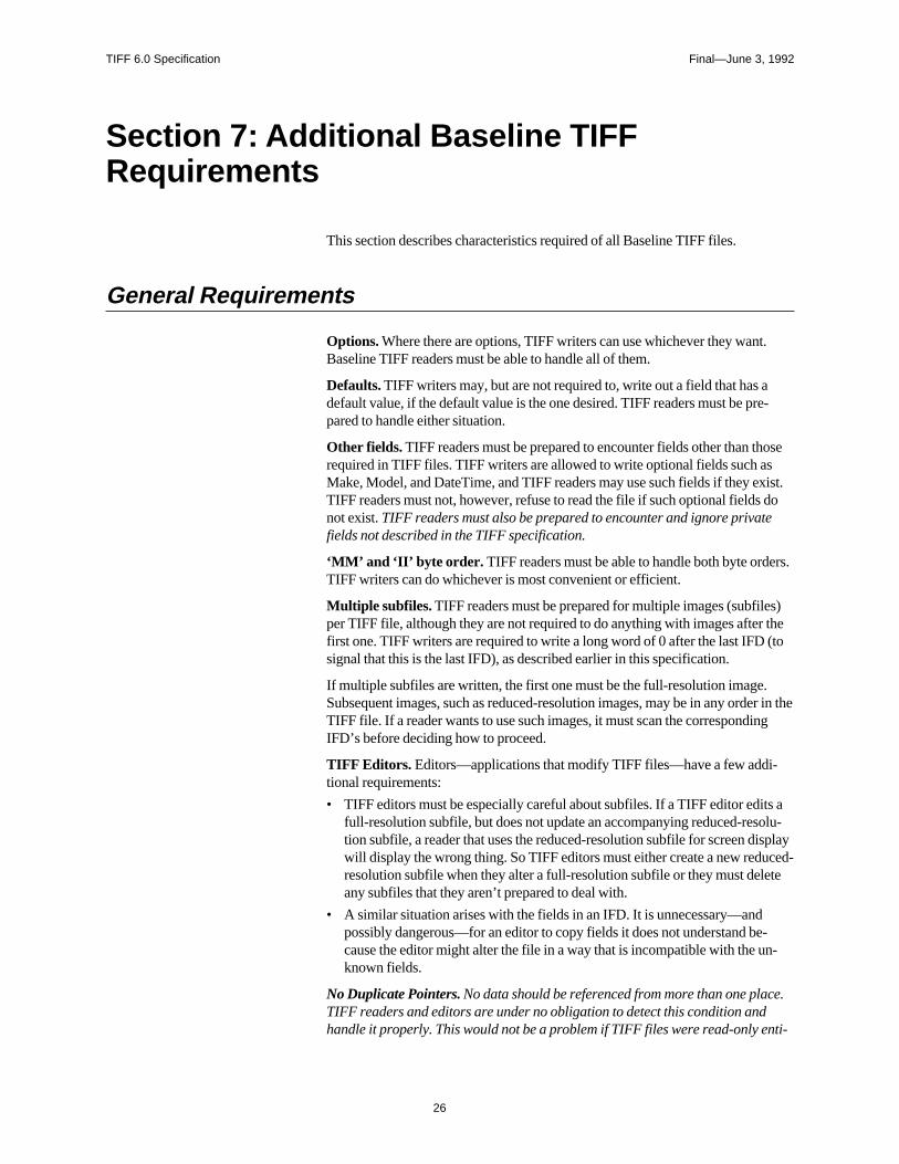
Section 7: Additional Baseline TIFFRequirements
This section describes characteristics required of all Baseline TIFF files.
General Requirements
Options. Where there are options, TIFF writers can use whichever they wantBaseline TIFF readers must be able to handle all of them.
Defaults. TIFF writers may, but are not required to, write out a field that has adefault value, if the default value is the one desired. TIFF readers must be prpared to handle either situation.
Other fields. TIFF readers must be prepared to encounter fields other than threquired in TIFF files. TIFF writers are allowed to write optional fields such asMake, Model, and DateTime, and TIFF readers may use such fields if they eTIFF readers must not, however, refuse to read the file if such optional fieldsnot exist. TIFF readers must also be prepared to encounter and ignore privatfields not described in the TIFF specification.
‘MM’ and ‘II’ byte order. TIFF readers must be able to handle both byte ordTIFF writers can do whichever is most convenient or efficient.
Multiple subfiles. TIFF readers must be prepared for multiple images (subfileper TIFF file, although they are not required to do anything with images afterfirst one. TIFF writers are required to write a long word of 0 after the last IFD signal that this is the last IFD), as described earlier in this specification.
If multiple subfiles are written, the first one must be the full-resolution image.Subsequent images, such as reduced-resolution images, may be in any ordTIFF file. If a reader wants to use such images, it must scan the correspondiIFD’s before deciding how to proceed.
TIFF Editors. Editors—applications that modify TIFF files—have a few addi-tional requirements:
• TIFF editors must be especially careful about subfiles. If a TIFF editor edifull-resolution subfile, but does not update an accompanying reduced-restion subfile, a reader that uses the reduced-resolution subfile for screen dwill display the wrong thing. So TIFF editors must either create a new reduresolution subfile when they alter a full-resolution subfile or they must deleany subfiles that they aren’t prepared to deal with.
• A similar situation arises with the fields in an IFD. It is unnecessary—andpossibly dangerous—for an editor to copy fields it does not understand because the editor might alter the file in a way that is incompatible with the uknown fields.
No Duplicate Pointers. No data should be referenced from more than one placTIFF readers and editors are under no obligation to detect this condition andhandle it properly. This would not be a problem if TIFF files were read-only e
26

TIFF 6.0 Specification Final—June 3, 1992
ields
l to
r
ple,ave
asully.s be
ft andmat
rmechably
riprunachsy for-rStrip
ypixel-ut
ties, but they are not. This warning covers both TIFF field value offsets and fthat are defined as offsets, such as StripOffsets.
Point to real data. All strip offsets must reference valid locations. (It is not legause an offset of 0 to mean something special.)
Beware of extra components. Some TIFF files may have more components pepixel than you think. A Baseline TIFF reader must skip over them gracefully,using the values of the SamplesPerPixel and BitsPerSample fields. For examit is possible that the data will have a PhotometricInterpretation of RGB but h4 SamplesPerPixel. See ExtraSamples for further details.
Beware of new field types. Be prepared to handle unexpected field types suchfloating-point data. A Baseline TIFF reader must skip over such fields gracefDo not expect that BYTE, ASCII, SHORT, LONG, and RATIONAL will alwaya complete list of field types.
Beware of new pixel types. Some TIFF files may have pixel data that consists osomething other than unsigned integers. If the SampleFormat field is presenthe value is not 1, a Baseline TIFF reader that cannot handle the SampleForvalue must terminate the import process gracefully.
Notes on Required Fields
ImageWidth, ImageLength. Both “SHORT” and “LONG” TIFF field types areallowed and must be handled properly by readers. TIFF writers can use eithetype. TIFF readers are not required to read arbitrarily large files however. Soreaders will give up if the entire image cannot fit into available memory. (In sucases the reader should inform the user about the problem.) Others will probnot be able to handle ImageWidth greater than 65535.
RowsPerStrip. SHORT or LONG. Readers must be able to handle any valuebetween 1 and 2**32-1. However, some readers may try to read an entire stinto memory at one time. If the entire image is one strip, the application may out of memory. Recommendation: Set RowsPerStrip such that the size of estrip is about 8K bytes. Do this even for uncompressed data because it is eaa writer and makes things simpler for readers. Note that extremely wide highresolution images may have rows larger than 8K bytes; in this case, RowsPeshould be 1, and the strip will be larger than 8K.
StripOffsets. SHORT or LONG.
StripByteCounts. SHORT or LONG.
XResolution, YResolution. RATIONAL. Note that the X and Y resolutions mabe unequal. A TIFF reader must be able to handle this case. Typically, TIFF editors do not care about the resolution, but applications (such as page layoprograms) do care.
ResolutionUnit. SHORT. TIFF readers must be prepared to handle all threevalues for ResolutionUnit.
27
TIFF 6.0 Specification Final—June 3, 1992
d in
ifica-is
tion.fieldsF
.
rer lists
eline
pixel.
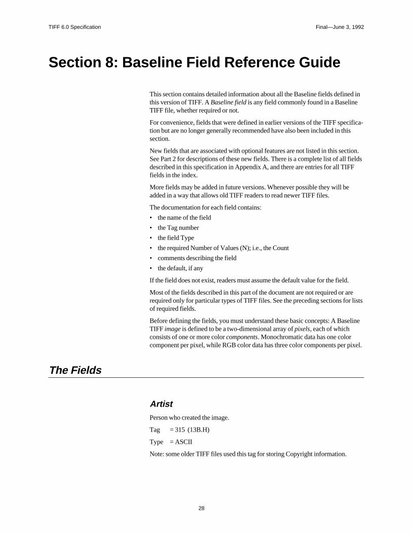
Section 8: Baseline Field Reference Guide
This section contains detailed information about all the Baseline fields definethis version of TIFF. A Baseline field is any field commonly found in a BaselineTIFF file, whether required or not.
For convenience, fields that were defined in earlier versions of the TIFF spection but are no longer generally recommended have also been included in thsection.
New fields that are associated with optional features are not listed in this secSee Part 2 for descriptions of these new fields. There is a complete list of all described in this specification in Appendix A, and there are entries for all TIFfields in the index.
More fields may be added in future versions. Whenever possible they will beadded in a way that allows old TIFF readers to read newer TIFF files.
The documentation for each field contains:
• the name of the field
• the Tag number
• the field Type
• the required Number of Values (N); i.e., the Count
• comments describing the field
• the default, if any
If the field does not exist, readers must assume the default value for the field
Most of the fields described in this part of the document are not required or arequired only for particular types of TIFF files. See the preceding sections foof required fields.
Before defining the fields, you must understand these basic concepts: A BasTIFF image is defined to be a two-dimensional array of pixels, each of whichconsists of one or more color components. Monochromatic data has one colorcomponent per pixel, while RGB color data has three color components per
The Fields
ArtistPerson who created the image.
Tag = 315 (13B.H)
Type = ASCII
Note: some older TIFF files used this tag for storing Copyright information.
28
TIFF 6.0 Specification Final—June 3, 1992
orinto
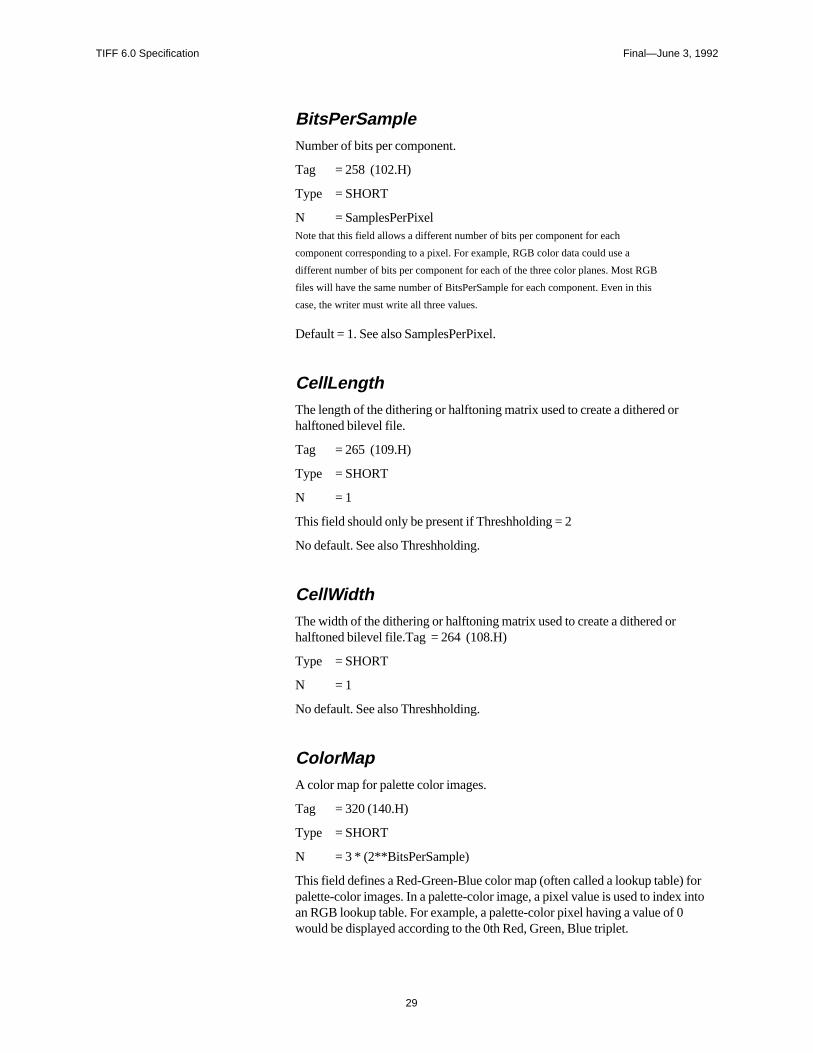
BitsPerSampleNumber of bits per component.
Tag = 258 (102.H)
Type = SHORT
N = SamplesPerPixelNote that this field allows a different number of bits per component for each
component corresponding to a pixel. For example, RGB color data could use a
different number of bits per component for each of the three color planes. Most RGB
files will have the same number of BitsPerSample for each component. Even in this
case, the writer must write all three values.
Default = 1. See also SamplesPerPixel.
CellLengthThe length of the dithering or halftoning matrix used to create a dithered orhalftoned bilevel file.
Tag = 265 (109.H)
Type = SHORT
N = 1
This field should only be present if Threshholding = 2
No default. See also Threshholding.
CellWidthThe width of the dithering or halftoning matrix used to create a dithered orhalftoned bilevel file.Tag = 264 (108.H)
Type = SHORT
N = 1
No default. See also Threshholding.
ColorMapA color map for palette color images.
Tag = 320 (140.H)
Type = SHORT
N = 3 * (2**BitsPerSample)
This field defines a Red-Green-Blue color map (often called a lookup table) fpalette-color images. In a palette-color image, a pixel value is used to index an RGB lookup table. For example, a palette-color pixel having a value of 0would be displayed according to the 0th Red, Green, Blue triplet.
29

TIFF 6.0 Specification Final—June 3, 1992
ues,ple. 256
entsis
nused
ith
ingr.ding
s
ed
In a TIFF ColorMap, all the Red values come first, followed by the Green valthen the Blue values. The number of values for each color is 2**BitsPerSamTherefore, the ColorMap field for an 8-bit palette-color image would have 3 *values.
The width of each value is 16 bits, as implied by the type of SHORT. 0 represthe minimum intensity, and 65535 represents the maximum intensity. Black represented by 0,0,0, and white by 65535, 65535, 65535.
See also PhotometricInterpretation—palette color.
No default. ColorMap must be included in all palette-color images.
CompressionCompression scheme used on the image data.
Tag = 259 (103.H)
Type = SHORT
N = 1
1 = No compression, but pack data into bytes as tightly as possible leaving no ubits except at the end of a row.
If Then the sample values are stored as an array of type:
BitsPerSample = 16 for all samples SHORT
BitsPerSample = 32 for all samples LONG
Otherwise BYTE
Each row is padded to the next BYTE/SHORT/LONG boundary, consistent wthe preceding BitsPerSample rule.
If the image data is stored as an array of SHORTs or LONGs, the byte ordermust be consistent with that specified in bytes 0 and 1 of the TIFF file headeTherefore, little-endian format files will have the least significant bytes precethe most significant bytes, while big-endian format files will have the oppositeorder.If the number of bits per component is not a power of 2, and you are willing to give up
some space for better performance, use the next higher power of 2. For example, if
your data can be represented in 6 bits, set BitsPerSample to 8 instead of 6, and then
convert the range of the values from [0,63] to [0,255].
Rows must begin on byte boundaries. (SHORT boundaries if the data is stored aSHORTs, LONG boundaries if the data is stored as LONGs).Some graphics systems require image data rows to be word-aligned or double-word-
aligned, and padded to word-boundaries or double-word boundaries. Uncompressed
TIFF rows will need to be copied into word-aligned or double-word-aligned row
buffers before being passed to the graphics routines in these environments.
2 = CCITT Group 3 1-Dimensional Modified Huffman run-length encoding. SeeSection 10. BitsPerSample must be 1, since this type of compression is definonly for bilevel images.
30
TIFF 6.0 Specification Final—June 3, 1992
tion 9
ng9xx.
rf the
dxel
eles
city,
32773 = PackBits compression, a simple byte-oriented run-length scheme. See Secfor details.
Data compression applies only to the image data, pointed to by StripOffsets.
Default = 1.
CopyrightCopyright notice.
Tag = 33432 (8298.H)
Type = ASCII
Copyright notice of the person or organization that claims the copyright to theimage. The complete copyright statement should be listed in this field includiany dates and statements of claims. For example, “Copyright, John Smith, 1All rights reserved.”
DateTimeDate and time of image creation.
Tag = 306 (132.H)
Type = ASCII
N = 20
The format is: “YYYY:MM:DD HH:MM:SS”, with hours like those on a 24-houclock, and one space character between the date and the time. The length ostring, including the terminating NUL, is 20 bytes.
ExtraSamplesDescription of extra components.
Tag = 338 (152.H)
Type = SHORT
N = m
Specifies that each pixel has m extra components whose interpretation is defineby one of the values listed below. When this field is used, the SamplesPerPifield has a value greater than the PhotometricInterpretation field suggests.
For example, full-color RGB data normally has SamplesPerPixel=3. IfSamplesPerPixel is greater than 3, then the ExtraSamples field describes thmeaning of the extra samples. If SamplesPerPixel is, say, 5 then ExtraSampwill contain 2 values, one for each extra sample.
ExtraSamples is typically used to include non-color information, such as opain an image. The possible values for each item in the field's value are:
0 = Unspecified data
1 = Associated alpha data (with pre-multiplied color)
31
TIFF 6.0 Specification Final—June 3, 1992
1.epen-
specifies
t com-xtrael-1)
In
field. 3.
re
r bit-
s-rst
re
s. Itokup
a is
2 = Unassociated alpha data
Associated alpha data is opacity information; it is fully described in Section 2Unassociated alpha data is transparency information that logically exists inddent of an image; it is commonly called a soft matte. Note that including bothunassociated and associated alpha is undefined because associated alpha that color components are pre-multiplied by the alpha component, whileunassociated alpha specifies the opposite.
By convention, extra components that are present must be stored as the “lasponents” in each pixel. For example, if SamplesPerPixel is 4 and there is 1 ecomponent, then it is located in the last component location (SamplesPerPixin each pixel.
Components designated as “extra” are just like other components in a pixel.particular, the size of such components is defined by the value of theBitsPerSample field.
With the introduction of this field, TIFF readers must not assume a particularSamplesPerPixel value based on the value of the PhotometricInterpretation For example, if the file is an RGB file, SamplesPerPixel may be greater than
The default is no extra samples. This field must be present if there are extrasamples.
See also SamplesPerPixel, AssociatedAlpha.
FillOrderThe logical order of bits within a byte.
Tag = 266 (10A.H)
Type = SHORT
N = 1
1 = pixels are arranged within a byte such that pixels with lower column values astored in the higher-order bits of the byte.
1-bit uncompressed data example: Pixel 0 of a row is stored in the high-ordeof byte 0, pixel 1 is stored in the next-highest bit, ..., pixel 7 is stored in the loworder bit of byte 0, pixel 8 is stored in the high-order bit of byte 1, and so on.
CCITT 1-bit compressed data example: The high-order bit of the first compresion code is stored in the high-order bit of byte 0, the next-highest bit of the ficompression code is stored in the next-highest bit of byte 0, and so on.
2 = pixels are arranged within a byte such that pixels with lower column values astored in the lower-order bits of the byte.
We recommend that FillOrder=2 be used only in special-purpose applicationis easy and inexpensive for writers to reverse bit order by using a 256-byte lotable. FillOrder = 2 should be used only when BitsPerSample = 1 and the dateither uncompressed or compressed using CCITT 1D or 2D compression, toavoid potentially ambigous situations.
Support for FillOrder=2 is not required in a Baseline TIFF compliant reader
Default is FillOrder = 1.
32

TIFF 6.0 Specification Final—June 3, 1992
s in
e
pixel
t is
is
g
.0.
FreeByteCountsFor each string of contiguous unused bytes in a TIFF file, the number of bytethe string.
Tag = 289 (121.H)
Type = LONG
Not recommended for general interchange.
See also FreeOffsets.
FreeOffsetsFor each string of contiguous unused bytes in a TIFF file, the byte offset of thstring.
Tag = 288 (120.H)
Type = LONG
Not recommended for general interchange.
See also FreeByteCounts.
GrayResponseCurveFor grayscale data, the optical density of each possible pixel value.
Tag = 291 (123.H)
Type = SHORT
N = 2**BitsPerSample
The 0th value of GrayResponseCurve corresponds to the optical density of ahaving a value of 0, and so on.
This field may provide useful information for sophisticated applications, but icurrently ignored by most TIFF readers.
See also GrayResponseUnit, PhotometricInterpretation.
GrayResponseUnitThe precision of the information contained in the GrayResponseCurve.
Tag = 290 (122.H)
Type = SHORT
N = 1
Because optical density is specified in terms of fractional numbers, this field necessary to interpret the stored integer information. For example, ifGrayScaleResponseUnits is set to 4 (ten-thousandths of a unit), and aGrayScaleResponseCurve number for gray level 4 is 3455, then the resultinactual value is 0.3455.
Optical densitometers typically measure densities within the range of 0.0 to 2
33
TIFF 6.0 Specification Final—June 3, 1992
com-
pic-
1 = Number represents tenths of a unit.
2 = Number represents hundredths of a unit.
3 = Number represents thousandths of a unit.
4 = Number represents ten-thousandths of a unit.
5 = Number represents hundred-thousandths of a unit.
Modifies GrayResponseCurve.
See also GrayResponseCurve.
For historical reasons, the default is 2. However, for greater accuracy, 3 is remended.
HostComputerThe computer and/or operating system in use at the time of image creation.
Tag = 316 (13C.H)
Type = ASCII
See also Make, Model, Software.
ImageDescriptionA string that describes the subject of the image.
Tag = 270 (10E.H)
Type = ASCII
For example, a user may wish to attach a comment such as “1988 companynic” to an image.
ImageLengthThe number of rows of pixels in the image.
Tag = 257 (101.H)
Type = SHORT or LONG
N = 1
No default. See also ImageWidth.
ImageWidthThe number of columns in the image, i.e., the number of pixels per row.
Tag = 256 (100.H)
Type = SHORT or LONG
N = 1
No default. See also ImageLength.
34
TIFF 6.0 Specification Final—June 3, 1992
to
it isr
quip-
MakeThe scanner manufacturer.
Tag = 271 (10F.H)
Type = ASCII
Manufacturer of the scanner, video digitizer, or other type of equipment usedgenerate the image. Synthetic images should not include this field.
See also Model, Software.
MaxSampleValueThe maximum component value used.
Tag = 281 (119.H)
Type = SHORT
N = SamplesPerPixel
This field is not to be used to affect the visual appearance of an image whendisplayed or printed. Nor should this field affect the interpretation of any othefield; it is used only for statistical purposes.
Default is 2**(BitsPerSample) - 1.
MinSampleValueThe minimum component value used.
Tag = 280 (118.H)
Type = SHORT
N = SamplesPerPixel
See also MaxSampleValue.
Default is 0.
ModelThe scanner model name or number.
Tag = 272 (110.H)
Type = ASCII
The model name or number of the scanner, video digitizer, or other type of ement used to generate the image.
See also Make, Software.
35
TIFF 6.0 Specification Final—June 3, 1992
ield.
. Bit 0
file;
r field
file.mask.
other.
sents
sents
epre-
epre-
lumn
olumn
olumn
NewSubfileTypeA general indication of the kind of data contained in this subfile.
Tag = 254 (FE.H)
Type = LONG
N = 1
Replaces the old SubfileType field, due to limitations in the definition of that f
NewSubfileType is mainly useful when there are multiple subfiles in a singleTIFF file.
This field is made up of a set of 32 flag bits. Unused bits are expected to be 0is the low-order bit.
Currently defined values are:
Bit 0 is 1 if the image is a reduced-resolution version of another image in this TIFFelse the bit is 0.
Bit 1 is 1 if the image is a single page of a multi-page image (see the PageNumbedescription); else the bit is 0.
Bit 2 is 1 if the image defines a transparency mask for another image in this TIFF The PhotometricInterpretation value must be 4, designating a transparency
These values are defined as bit flags because they are independent of each
Default is 0.
OrientationThe orientation of the image with respect to the rows and columns.
Tag = 274 (112.H)
Type = SHORT
N = 1
1 = The 0th row represents the visual top of the image, and the 0th column reprethe visual left-hand side.
2 = The 0th row represents the visual top of the image, and the 0th column reprethe visual right-hand side.
3 = The 0th row represents the visual bottom of the image, and the 0th column rsents the visual right-hand side.
4 = The 0th row represents the visual bottom of the image, and the 0th column rsents the visual left-hand side.
5 = The 0th row represents the visual left-hand side of the image, and the 0th corepresents the visual top.
6 = The 0th row represents the visual right-hand side of the image, and the 0th crepresents the visual top.
7 = The 0th row represents the visual right-hand side of the image, and the 0th crepresents the visual bottom.
36
TIFF 6.0 Specification Final—June 3, 1992
lumn
-
ri-ch ofle - 1
ck,
irstr thet planesets.
ees in
nother.re-
tok areits in
8 = The 0th row represents the visual left-hand side of the image, and the 0th corepresents the visual bottom.
Default is 1.
Support for orientations other than 1 is not a Baseline TIFF requirement.
PhotometricInterpretationThe color space of the image data.
Tag = 262 (106.H)
Type = SHORT
N = 1
0 = WhiteIsZero. For bilevel and grayscale images: 0 is imaged as white.2**BitsPerSample-1 is imaged as black. This is the normal value for Compres-sion=2.
1 = BlackIsZero. For bilevel and grayscale images: 0 is imaged as black.2**BitsPerSample-1 is imaged as white. If this value is specified for Compression=2, the image should display and print reversed.
2 = RGB. In the RGB model, a color is described as a combination of the three pmary colors of light (red, green, and blue) in particular concentrations. For eathe three components, 0 represents minimum intensity, and 2**BitsPerSamprepresents maximum intensity. Thus an RGB value of (0,0,0) represents blaand (255,255,255) represents white, assuming 8-bit components. ForPlanarConfiguration = 1, the components are stored in the indicated order: fRed, then Green, then Blue. For PlanarConfiguration = 2, the StripOffsets focomponent planes are stored in the indicated order: first the Red componenStripOffsets, then the Green plane StripOffsets, then the Blue plane StripOff
3= Palette color. In this model, a color is described with a single component. Thvalue of the component is used as an index into the red, green and blue curvthe ColorMap field to retrieve an RGB triplet that defines the color. WhenPhotometricInterpretation=3 is used, ColorMap must be present andSamplesPerPixel must be 1.
4 = Transparency Mask.
This means that the image is used to define an irregularly shaped region of aimage in the same TIFF file. SamplesPerPixel and BitsPerSample must be 1PackBits compression is recommended. The 1-bits define the interior of the gion; the 0-bits define the exterior of the region.
A reader application can use the mask to determine which parts of the imagedisplay. Main image pixels that correspond to 1-bits in the transparency masimaged to the screen or printer, but main image pixels that correspond to 0-bthe mask are not displayed or printed.
The image mask is typically at a higher resolution than the main image, if themain image is grayscale or color so that the edges can be sharp.
There is no default for PhotometricInterpretation, and it is required. Do not relyon applications defaulting to what you want.
37
TIFF 6.0 Specification Final—June 3, 1992
.
Theionalol-
ntpo-
-F
-
are
PlanarConfigurationHow the components of each pixel are stored.
Tag = 284 (11C.H)
Type = SHORT
N = 1
1 = Chunky format. The component values for each pixel are stored contiguouslyThe order of the components within the pixel is specified byPhotometricInterpretation. For example, for RGB data, the data is stored asRGBRGBRGB…
2 = Planar format. The components are stored in separate “component planes.” values in StripOffsets and StripByteCounts are then arranged as a 2-dimensarray, with SamplesPerPixel rows and StripsPerImage columns. (All of the cumns for row 0 are stored first, followed by the columns of row 1, and so on.)PhotometricInterpretation describes the type of data stored in each componeplane. For example, RGB data is stored with the Red components in one comnent plane, the Green in another, and the Blue in another.
PlanarConfiguration=2 is not currently in widespread use and it is not recommended for general interchange. It is used as an extension and Baseline TIFreaders are not required to support it.
If SamplesPerPixel is 1, PlanarConfiguration is irrelevant, and need not be included.If a row interleave effect is desired, a writer might write out the data as
PlanarConfiguration=2—separate sample planes—but break up the planes into
multiple strips (one row per strip, perhaps) and interleave the strips.
Default is 1. See also BitsPerSample, SamplesPerPixel.
ResolutionUnitThe unit of measurement for XResolution and YResolution.
Tag = 296 (128.H)
Type = SHORT
N = 1
To be used with XResolution and YResolution.
1 = No absolute unit of measurement. Used for images that may have a non-squaspect ratio, but no meaningful absolute dimensions.The drawback of ResolutionUnit=1 is that different applications will import the image
at different sizes. Even if the decision is arbitrary, it might be better to use dots per
inch or dots per centimeter, and to pick XResolution and YResolution so that the
aspect ratio is correct and the maximum dimension of the image is about four inches
(the “four” is arbitrary.)
2 = Inch.
3 = Centimeter.
Default is 2.
38
TIFF 6.0 Specification Final—June 3, 1992
nt I/O
s
,
ge.
RowsPerStripThe number of rows per strip.
Tag = 278 (116.H)
Type = SHORT or LONG
N = 1
TIFF image data is organized into strips for faster random access and efficiebuffering.RowsPerStrip and ImageLength together tell us the number of strips in the entire
image. The equation is:
StripsPerImage = floor ((ImageLength + RowsPerStrip - 1) / RowsPerStrip).
StripsPerImage is not a field. It is merely a value that a TIFF reader will want to
compute because it specifies the number of StripOffsets and StripByteCounts for the
image.
Note that either SHORT or LONG values can be used to specify RowsPerStrip.
SHORT values may be used for small TIFF files. It should be noted, however, that
earlier TIFF specification revisions required LONG values and that some software
may not accept SHORT values.
The default is 2**32 - 1, which is effectively infinity. That is, the entire image ione strip.Use of a single strip is not recommended. Choose RowsPerStrip such that each strip is
about 8K bytes, even if the data is not compressed, since it makes buffering simpler
for readers. The “8K” value is fairly arbitrary, but seems to work well.
See also ImageLength, StripOffsets, StripByteCounts, TileWidth, TileLengthTileOffsets, TileByteCounts.
SamplesPerPixelThe number of components per pixel.
Tag = 277 (115.H)
Type = SHORT
N = 1
SamplesPerPixel is usually 1 for bilevel, grayscale, and palette-color images.SamplesPerPixel is usually 3 for RGB images.
Default = 1. See also BitsPerSample, PhotometricInterpretation, ExtraSamples.
SoftwareName and version number of the software package(s) used to create the ima
Tag = 305 (131.H)
Type = ASCII
See also Make, Model.
39
TIFF 6.0 Specification Final—June 3, 1992
2
2
t thisrips.
sets.r, thatre
in-gth,ould
StripByteCountsFor each strip, the number of bytes in the strip after compression.
Tag = 279 (117.H)
Type = SHORT or LONG
N = StripsPerImage for PlanarConfiguration equal to 1.
= SamplesPerPixel * StripsPerImage for PlanarConfiguration equal to
This tag is required for Baseline TIFF files.
No default.
See also StripOffsets, RowsPerStrip, TileOffsets, TileByteCounts.
StripOffsetsFor each strip, the byte offset of that strip.
Tag = 273 (111.H)
Type = SHORT or LONG
N = StripsPerImage for PlanarConfiguration equal to 1.
= SamplesPerPixel * StripsPerImage for PlanarConfiguration equal to
The offset is specified with respect to the beginning of the TIFF file. Note thaimplies that each strip has a location independent of the locations of other stThis feature may be useful for editing applications. This required field is the onlyway for a reader to find the image data. (Unless TileOffsets is used; seeTileOffsets.)
Note that either SHORT or LONG values may be used to specify the strip offSHORT values may be used for small TIFF files. It should be noted, howeveearlier TIFF specifications required LONG strip offsets and that some softwamay not accept SHORT values.
For maximum compatibility with operating systems such as MS-DOS and Wdows, the StripOffsets array should be less than or equal to 64K bytes in lenand the strips themselves, in both compressed and uncompressed forms, shnot be larger than 64K bytes.
No default. See also StripByteCounts, RowsPerStrip, TileOffsets,TileByteCounts.
SubfileTypeA general indication of the kind of data contained in this subfile.
Tag = 255 (FF.H)
Type = SHORT
N = 1
40
TIFF 6.0 Specification Final—June 3, 1992
.
ubfile
sed to
data.
Currently defined values are:
1 = full-resolution image data
2 = reduced-resolution image data
3 = a single page of a multi-page image (see the PageNumber field description)
Note that several image types may be found in a single TIFF file, with each sdescribed by its own IFD.
No default.
This field is deprecated. The NewSubfileType field should be used instead.
ThreshholdingFor black and white TIFF files that represent shades of gray, the technique uconvert from gray to black and white pixels.
Tag = 263 (107.H)
Type = SHORT
N = 1
1 = No dithering or halftoning has been applied to the image data.
2 = An ordered dither or halftone technique has been applied to the image data.
3 = A randomized process such as error diffusion has been applied to the image
Default is Threshholding = 1. See also CellWidth, CellLength.
XResolutionThe number of pixels per ResolutionUnit in the ImageWidth direction.
Tag = 282 (11A.H)
Type = RATIONAL
N = 1It is not mandatory that the image be actually displayed or printed at the size implied
by this parameter. It is up to the application to use this information as it wishes.
No default. See also YResolution, ResolutionUnit.
YResolutionThe number of pixels per ResolutionUnit in the ImageLength direction.
Tag = 283 (11B.H)
Type = RATIONAL
N = 1
No default. See also XResolution, ResolutionUnit.
41
TIFF 6.0 Specification Final—June 3, 1992
run-
trarilyviorlboxle-
unmerge runs.
+ 7)tes per
r more
r com-
Section 9: PackBits Compression
This section describes TIFF compression type 32773, a simple byte-orientedlength scheme.
Description
In choosing a simple byte-oriented run-length compression scheme, we arbichose the Apple Macintosh PackBits scheme. It has a good worst case beha(at most 1 extra byte for every 128 input bytes). For Macintosh users, the tooutilities PackBits and UnPackBits will do the work for you, but it is easy to impment your own routines.
A pseudo code fragment to unpack might look like this:Loop until you get the number of unpacked bytes you are expecting:
Read the next source byte into n.
If n is between 0 and 127 inclusive, copy the next n+1 bytes literally.
Else if n is between -127 and -1 inclusive, copy the next byte -n+1times.
Else if n is -128, noop.
Endloop
In the inverse routine, it is best to encode a 2-byte repeat run as a replicate rexcept when preceded and followed by a literal run. In that case, it is best to the three runs into one literal run. Always encode 3-byte repeats as replicate
That is the essence of the algorithm. Here are some additional rules:
• Pack each row separately. Do not compress across row boundaries.
• The number of uncompressed bytes per row is defined to be (ImageWidth/ 8. If the uncompressed bitmap is required to have an even number of byrow, decompress into word-aligned buffers.
• If a run is larger than 128 bytes, encode the remainder of the run as one oadditional replicate runs.
When PackBits data is decompressed, the result should be interpreted as pepression type 1 (no compression).
42

TIFF 6.0 Specification Final—June 3, 1992
ing.
n,”done
ac-i-
5,
t Com-rma-
ite to
oto-
es canap-
achnelow.)
, all
hites arength
Section 10: Modified Huffman Compression
This section describes TIFF compression scheme 2, a method for compressbilevel data based on the CCITT Group 3 1D facsimile compression scheme
References
• “Standardization of Group 3 facsimile apparatus for document transmissioRecommendation T.4, Volume VII, Fascicle VII.3, Terminal Equipment anProtocols for Telematic Services, The International Telegraph and TelephConsultative Committee (CCITT), Geneva, 1985, pages 16 through 31.
• “Facsimile Coding Schemes and Coding Control Functions for Group 4 Fsimile Apparatus,” Recommendation T.6, Volume VII, Fascicle VII.3, Termnal Equipment and Protocols for Telematic Services, The InternationalTelegraph and Telephone Consultative Committee (CCITT), Geneva, 198pages 40 through 48.
We do not believe that these documents are necessary in order to implemenpression=2. We have included (verbatim in most places) all the pertinent infotion in this section. However, if you wish to order the documents, you can wrANSI, Attention: Sales, 1430 Broadway, New York, N.Y., 10018. Ask for thepublication listed above—it contains both Recommendation T.4 and T.6.
Relationship to the CCITT Specifications
The CCITT Group 3 and Group 4 specifications describe communications prcols for a particular class of devices. They are not by themselves sufficient todescribe a disk data format. Fortunately, however, the CCITT coding schembe readily adapted to this different environment. The following is one such adtation. Most of the language is copied directly from the CCITT specifications.
See Section 11 for additional CCITT compression options.
Coding Scheme
A line (row) of data is composed of a series of variable length code words. Ecode word represents a run length of all white or all black. (Actually, more thaone code word may be required to code a given run, in a manner described bWhite runs and black runs alternate.
To ensure that the receiver (decompressor) maintains color synchronizationdata lines begin with a white run-length code word set. If the actual scan linebegins with a black run, a white run-length of zero is sent (written). Black or wrun-lengths are defined by the code words in Tables 1 and 2. The code wordof two types: Terminating code words and Make-up code words. Each run-leis represented by zero or more Make-up code words followed by exactly oneTerminating code word.
43

TIFF 6.0 Specification Final—June 3, 1992
priateck
e than,g
ed by
edrstfels.ke-up
does
s at
lackrts
s
the
Run lengths in the range of 0 to 63 pels (pixels) are encoded with their approTerminating code word. Note that there is a different list of code words for blaand white run-lengths.
Run lengths in the range of 64 to 2623 (2560+63) pels are encoded first by thMake-up code word representing the run-length that is nearest to, not longerthat required. This is then followed by the Terminating code word representinthe difference between the required run-length and the run-length representthe Make-up code.
Run lengths in the range of lengths longer than or equal to 2624 pels are codfirst by the Make-up code of 2560. If the remaining part of the run (after the fiMake-up code of 2560) is 2560 pels or greater, additional Make-up code(s) o2560 are issued until the remaining part of the run becomes less than 2560 pThen the remaining part of the run is encoded by Terminating code or by Macode plus Terminating code, according to the range mentioned above.
It is considered an unrecoverable error if the sum of the run-lengths for a linenot equal the value of the ImageWidth field.
New rows always begin on the next available byte boundary.
No EOL code words are used. No fill bits are used, except for the ignored bitthe end of the last byte of a row. RTC is not used.
An encoded CCITT string is self-photometric, defined in terms of white and bruns. Yet TIFF defines a tag called PhotometricInterpretation that also purpoto define what is white and what is black. Somewhat arbitrarily, we adopt thefollowing convention:
The “normal” PhotometricInterpretation for bilevel CCITT compressed data iWhiteIsZero. In this case, the CCITT “white” runs are to be interpretated aswhite, and the CCITT “black” runs are to be interpreted as black. However, ifPhotometricInterpretation is BlackIsZero, the TIFF reader must reverse themeaning of white and black when displaying and printing the image.
44
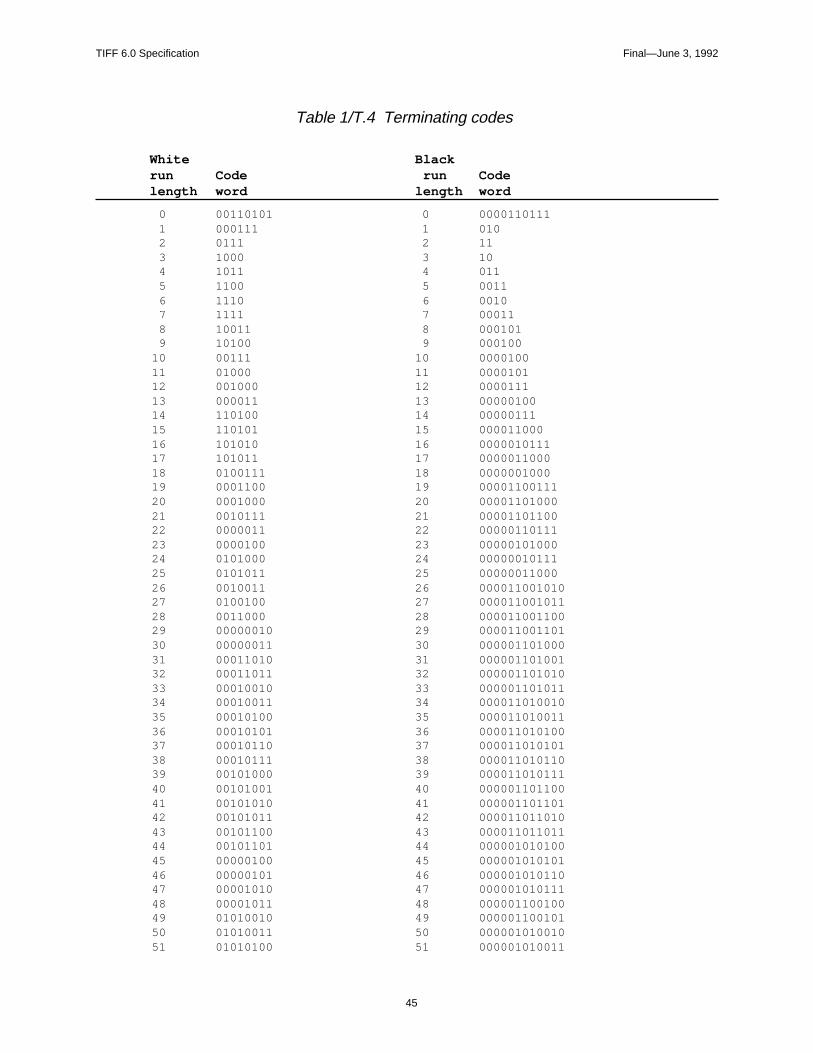
TIFF 6.0 Specification Final—June 3, 1992
Table 1/T.4 Terminating codes
White Blackrun Code run Codelength word length word
0 00110101 0 0000110111 1 000111 1 010 2 0111 2 11 3 1000 3 10 4 1011 4 011 5 1100 5 0011 6 1110 6 0010 7 1111 7 00011 8 10011 8 000101 9 10100 9 00010010 00111 10 000010011 01000 11 000010112 001000 12 000011113 000011 13 0000010014 110100 14 0000011115 110101 15 00001100016 101010 16 000001011117 101011 17 000001100018 0100111 18 000000100019 0001100 19 0000110011120 0001000 20 0000110100021 0010111 21 0000110110022 0000011 22 0000011011123 0000100 23 0000010100024 0101000 24 0000001011125 0101011 25 0000001100026 0010011 26 00001100101027 0100100 27 00001100101128 0011000 28 00001100110029 00000010 29 00001100110130 00000011 30 00000110100031 00011010 31 00000110100132 00011011 32 00000110101033 00010010 33 00000110101134 00010011 34 00001101001035 00010100 35 00001101001136 00010101 36 00001101010037 00010110 37 00001101010138 00010111 38 00001101011039 00101000 39 00001101011140 00101001 40 00000110110041 00101010 41 00000110110142 00101011 42 00001101101043 00101100 43 00001101101144 00101101 44 00000101010045 00000100 45 00000101010146 00000101 46 00000101011047 00001010 47 00000101011148 00001011 48 00000110010049 01010010 49 00000110010150 01010011 50 00000101001051 01010100 51 000001010011
45

TIFF 6.0 Specification Final—June 3, 1992
White Blackrun Code run Codelength word length word
52 01010101 52 00000010010053 00100100 53 00000011011154 00100101 54 00000011100055 01011000 55 00000010011156 01011001 56 00000010100057 01011010 57 00000101100058 01011011 58 00000101100159 01001010 59 00000010101160 01001011 60 00000010110061 00110010 61 00000101101062 00110011 62 00000110011063 00110100 63 000001100111
Table 2/T.4 Make-up codes
White Blackrun Code run Codelength word length word
64 11011 64 0000001111 128 10010 128 000011001000 192 010111 192 000011001001 256 0110111 256 000001011011 320 00110110 320 000000110011 384 00110111 384 000000110100 448 01100100 448 000000110101 512 01100101 512 0000001101100 576 01101000 576 0000001101101 640 01100111 640 0000001001010 704 011001100 704 0000001001011 768 011001101 768 0000001001100 832 011010010 832 0000001001101 896 011010011 896 0000001110010 960 011010100 960 00000011100111024 011010101 1024 00000011101001088 011010110 1088 00000011101011152 011010111 1152 00000011101101216 011011000 1216 00000011101111280 011011001 1280 00000010100101344 011011010 1344 00000010100111408 011011011 1408 00000010101001472 010011000 1472 00000010101011536 010011001 1536 00000010110101600 010011010 1600 00000010110111664 011000 1664 00000011001001728 010011011 1728 0000001100101 EOL 000000000001 EOL 00000000000
46
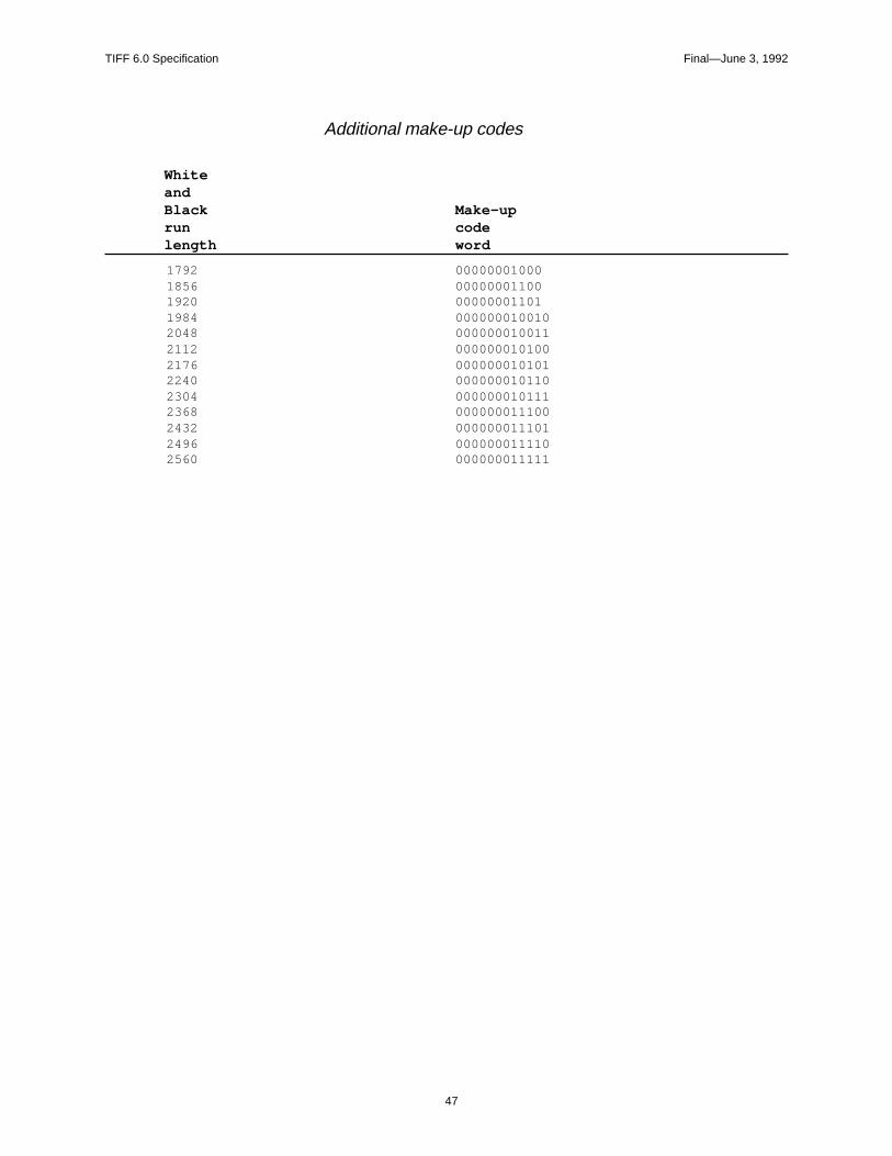
TIFF 6.0 Specification Final—June 3, 1992
Additional make-up codes
WhiteandBlack Make-uprun codelength word
1792 000000010001856 000000011001920 000000011011984 0000000100102048 0000000100112112 0000000101002176 0000000101012240 0000000101102304 0000000101112368 0000000111002432 0000000111012496 0000000111102560 000000011111
47

TIFF 6.0 Specification Final—June 3, 1992
res fea-
f the
Part 2: TIFF ExtensionsPart 2 contains extensions to Baseline TIFF. TIFF Extensions are TIFF featuthat may not be supported by all TIFF readers. TIFF creators who use thesetures will have to work closely with TIFF readers in their part of the industry toensure successful interchange.
The features described in this part were either contained in earlier versions ospecification, or have been approved by the TIFF Advisory Committee.
48
TIFF 6.0 Specification Final—June 3, 1992
eO
These-
ely
oftusative
nsnsul-
-by--levelg thetlysent a
portrity andd for of the
Section 11: CCITT Bilevel Encodings
The following fields are used when storing binary pixel arrays using one of thencodings adopted for raster-graphic interchange in numerous CCITT and IS(International Organization for Standards) recommendations and standards.encodings are often spoken of as “Group III compression” and “Group IV compression” because their application in facsimile transmission is the most widknown.For the specialized use of these encodings in storing facsimile-transmission images,
further guidelines can be obtained from the TIFF Class F document, available on-line
in the same locations as this specification. This document is administered by another
organization; paper copies are not available from Adobe.
CompressionTag = 259 (103.H)
Type = SHORT
N = 1
3 = T4-encoding: CCITT T.4 bi-level encoding as specified in section 4, Coding,CCITT Recommendation T.4: “Standardization of Group 3 Facsimile apparafor document transmission.” International Telephone and Telegraph ConsultCommittee (CCITT, Geneva: 1988).
See the T4Options field for T4-encoding options such as 1D vs 2D coding.
4 = T6-encoding: CCITT T.6 bi-level encoding as specified in section 2 of CCITTRecommendation T.6: “Facsimile coding schemes and coding control functiofor Group 4 facsimile apparatus.” International Telephone and Telegraph Cotative Committee (CCITT, Geneva: 1988).
See the T6Options field for T6-encoding options such as escape intouncompressed mode to avoid negative-compression cases.
Application in Image InterchangeCCITT Recommendations T.4 and T.6 are specified in terms of the serial bitbit creation and processing of a variable-length binary string that encodes bi(black and white) pixels of a rectangular image array. Generally, the encodinschemes are described in terms of bit-serial communication procedures andend-to-end coordination that is required to gain reliable delivery over inherenunreliable data links. The Group 4 procedures, with their T6-encoding, represignificant simplification because it is assumed that a reliable communicationmedium is employed, whether ISDN or X.25 or some other trustworthy transvehicle. Because image-storage systems and computers achieve data integcommunication reliability in other ways, the T6-encoding tends to be prefereimaging applications. When computer storage and retrieval and interchangefacsimile material are of interest, the T4-encodings provide a better match to
49
TIFF 6.0 Specification Final—June 3, 1992
data
eigi-
is
shite,
ean-
mu-r of: In
de-ionory
emblyled be-
suchtF
t char- data-
ts into ex- forsng is
ngs, 3
nces-
current generation of Group 3 facsimile products and their defenses against corruption as the result of transmission defects.
Whichever form of encoding is preferable for a given application, there are anumber of adjustments that need to be made to account for the capture of thCCITT binary-encoding strings as part of electronically-stored material and dtal-image interchange.
PhotometricInterpretation. An encoded CCITT string is self-photometric, de-fined in terms of white and black runs. Yet TIFF defines a tag calledPhotometricInterpretation that also purports to define what is white and whatblack. Somewhat arbitrarily, we adopt the following convention:
The “normal” PhotometricInterpretation for bilevel CCITT compressed data iWhiteIsZero. In this case, the CCITT “white” runs are to be interpretated as wand the CCITT “black” runs are to be interpreted as black. However, if thePhotometricInterpretation is BlackIsZero, the TIFF reader must reverse the ming of white and black when displaying and printing the image.
FillOrder. When CCITT encodings are used directly over a typical serial comnication link, the order of the bits in the encoded string is the sequential ordethe string, bit-by-bit, from beginning to end. This poses the following questionwhich order should consecutive blocks of eight bits be assembled into octets(standard data bytes) for use within a computer system? The answer differs pending on whether we are concerned about preserving the serial-transmisssequence or preserving only the format of byte-organized sequences in memand in stored files.
From the perspective of electronic interchange, as long as a receiver’s reassof bits into bytes properly mirrors the way in which the bytes were disassembby the transmitter, no one cares which order is seen on the transmission linkcause each multiple of 8 bits is transparently transmitted.
Common practice is to record arbitrary binary strings into storage sequencesthat the first sequential bit of the string is found in the high-order bit of the firsoctet of the stored byte sequence. This is the standard case specified by TIFFillOrder = 1, used in most bitmap interchange and the only case required inBaseline TIFF. This is also the approach used for the octets of standard 8-biacter data, with little attention paid to the fact that the most common forms ofcommunication transmit and reassemble individual 8-bit frames with the loworder-bit first!
For bit-serial transmission to a distant unit whose approach to assembling bibytes is unknown and supposed to be irrelevant, it is necessary to satisfy thepected sequencing of bits over the transmission link. This is the normal casecommunication between facsimile units and also for computers and modememulating standard Group 3 facsimile units. In this case, if the CCITT encodicaptured directly off of the link via standard communication adapters, TIFFFillOrder = 2 will usually apply to that stored data form.
Consequently, different TIFF FillOrder cases may arise when CCITT encodiare obtained by synthesis within a computer (including Group 4 transmissionwhich is treated more like computer data) instead of by capture from a Groupfacsimile unit.
Because this is such a subtle situation, with surprisingly disruptive consequefor FillOrder mismatches, the following practice is urged whenever CCITT bilevel encodings are used:
50

TIFF 6.0 Specification Final—June 3, 1992
rialpreadon-
ientnt. “leak-arn
n
ed
nting are
-
lyt lines, to bey
tlysig-r-d.eens.end-i-
For-
a. TIFF FillOrder (tag 266) should always be explicitly specified.
b. FillOrder = 1 should be employed wherever possible in persistent matethat is intended for interchange. This is the only reliable case for widesinterchange among computer systems, and it is important to explicitly cfirm the honoring of standard assumptions.
c. FillOrder = 2 should occur only in highly-localized and preferably-transmaterial, as in a facsimile server supporting group 3 facsimile equipmeThe tag should be present as a safeguard against the CCITT encodinging” into an unsuspecting application, allowing readers to detect and wagainst the occurence.
There are interchange situations where fill order is not distinguished, as whefiltering the CCITT encoding into a PostScript level 2 image operation. In thiscase, as in most other cases of computer-based information interchange,FillOrder=1 is assumed, and any padding to a multiple of 8 bits is accomplishby adding a sufficient number of 0-bits to the end of the sequence.
Strips and Tiles. When CCITT bi-level encoding is employed, interaction withstripping (Section 3) and tiling (Section 15) is as follows:
a. Decompose the image into segments—individual pixel arrays represethe desired strip or tile configuration. The CCITT encoding proceduresapplied most flexibly if the segments each have a multiple of 4 lines.
b. Individually encode each segment according to the specified CCITT bilevel encoding, as if each segment is a separate raster-graphic image.
The reason for this general rule is that CCITT bi-level encodings are generalprogressive. That is, the initial line of pixels is encoded, and then subsequenaccording to a variety of options, are encoded in terms of changes that needmade to the preceding (unencoded) line. For strips and tiles to be individuallusable, they must each start as fresh, independent encodings.
Miscellaneous features. There are provisions in CCITT encoding that are mosmeaningful during facsimile-transmission procedures. There is generally no nificant application when storing images in TIFF or other data interchange fomats, although TIFF applications should be tolerant and flexible in this regarThese features tend to have significance only when facilitating transfer betwfacsimile and non-facsimile applications of the encoded raster-graphic imageFurther considerations for fill sequences, end-of-line flags, return-to-control (of-block) sequences and byte padding are introduced in discussion of the indvidual encoding options.
T4OptionsTag = 292 (124.H)
Type = LONG
N = 1
See Compression=3. This field is made up of a set of 32 flag bits. Unused bitsmust be set to 0. Bit 0 is the low-order bit.
Bit 0 is 1 for 2-dimensional coding (otherwise 1-dimensional is assumed). 2-D coding, if more than one strip is specified, each strip must begin with a 1
51
TIFF 6.0 Specification Final—June 3, 1992
am-
that byte
anceg has
appli-
-
rate
thesro-2-
fof ifeding
code
dingisionsthe by
dimensionally coded line. That is, RowsPerStrip should be a multiple of “Pareter K,” as documented in the CCITT specification.
Bit 1 is 1 if uncompressed mode is used.
Bit 2 is 1 if fill bits have been added as necessary before EOL codes such EOL always ends on a byte boundary, thus ensuring an EOL-sequence of 1preceded by a zero nibble: xxxx-0000 0000-0001.
Default is 0, for basic 1-dimensional coding. See also Compression.
T6OptionsTag = 293 (125.H)
Type = LONG
N = 1
See Compression = 4. This field is made up of a set of 32 flag bits. Unused bitsmust be set to 0. Bit 0 is the low-order bit. The default value is 0 (all bits 0).
bit 0 is unused and always 0.
bit 1 is 1 if uncompressed mode is allowed in the encoding.
In earlier versions of TIFF, this tag was named Group4Options. The significhas not changed and the present definition is compatible. The name of the tabeen changed to be consistent with the nomenclature of other T.6-encodingcations.
Readers should honor this option tag, and only this option tag, whenever T.6Encoding is specified for Compression.
For T.6-Encoding, each segment (strip or tile) is encoded as if it were a sepaimage. The encoded string from each segment starts a fresh byte.
There are no one-dimensional line encodings in T.6-Encoding. Instead, evenfirst row of the segment’s pixel array is encoded two-dimensionally by alwayassuming an invisible preceding row of all-white pixels. The 2-dimensional pcedure for encoding the body of individual rows is the same as that used for dimensional T.4-encoding and is described fully in the CCITT specifications.
The beginning of the encoding for each row of a strip or tile is conducted as ithere is an imaginary preceding (0-width) white pixel, that is as if a fresh run white pixels has just commenced. The completion of each line is encoded asthere are imaginary pixels beyond the end of the current line, and of the precline, in effect, of colors chosen such that the line is exactly completable by a word, making the imaginary next pixel a changing element that’s not actuallyused.
The encodings of successive lines follow contiguously in the binary T.6-Encostream with no special initiation or separation codewords. There are no provfor fill codes or explicit end-of-line indicators. The encoding of the last line of pixel array is followed immediately, in place of any additional line encodings,a 24-bit End-of-Facsimile Block (EOFB).
000000000001000000000001.B.
52
TIFF 6.0 Specification Final—June 3, 1992
he
outT.6-ging
lyingd
tethis
eth,
s,
one isoningidthal
beenf an
als.areca-ether
aheple of
duc--r of
lt-chor
itsy- its
The EOFB sequence is immediately followed by enough 0-bit padding to fit tentire stream into a sequence of 8-bit bytes.
General Application. Because of the single uniform encoding procedure, withdisruptions by end-of-line codes and shifts into one-dimensional encodings, encoding is very popular for compression of bi-level images in document imasystems. T.6-encoding trades off redundancy for minimum encoded size, reon the underlying storage and transmission systems for reliable retention ancommunication of the encoded stream.
TIFF readers will operate most smoothly by always ignoring bits beyond theEOFB. Some writers may produce additional bytes of pad bits beyond the bycontaining the final bit of the EOFB. Robust readers will not be disturbed by prospect.
It is not possible to correctly decode a T.6-Encoding without knowledge of thexact number of pixels in each line of the pixel array. ImageWidth (or TileWidif used) must be stated exactly and accurately. If an image or segment isoverscanned, producing extraneous pixels at the beginning or ending of linethese pixels must be counted. Any cropping must be accomplished by othermeans. It is not possible to recover from a pixel-count deviation, even when detected. Failure of any row to be completed as expected is cause for abandfurther decoding of the entire segment. There is no requirement that ImageWbe a multiple of eight, of course, and readers must be prepared to pad the finoctet bytes of decoded bitmap rows with additional bits.
If a TIFF reader encounters EOFB before the expected number of lines has extracted, it is appropriate to assume that the missing rows consist entirely owhite pixels. Cautious readers might produce an unobtrusive warning if suchEOFB is followed by anything other than pad bits.
Readers that successfully decode the RowsPerStrip (or TileLength or residuImageLength) number of lines are not required to verify that an EOFB followThat is, it is generally appropriate to stop decoding when the expected lines decoded or the EOFB is detected, whichever occurs first. Whether error inditions or warnings are also appropriate depends upon the application and whmore precise troubleshooting of encoding deviations is important.
TIFF writers should always encode the full, prescribed number of rows, with proper EOFB immediately following in the encoding. Padding should be by tleast number of 0-bits needed for the T.6-encoding to exactly occupy a multi8 bits. Only 0-bits should be used for padding, and StripByteCount (orTileByteCount) should not extend to any bytes not containing properly-formeT.6-encoding. In addition, even though not required by T.6-encoding rules, scessful interchange with a large variety of readers and applications will be enhanced if writers can arrange for the number of pixels per line and the numbelines per strip to be multiples of eight.
Uncompressed Mode. Although T.6-encodings of simple bi-level images resuin data compressions of 10:1 and better, some pixel-array patterns have T.6encodings that require more bits than their simple bi-level bitmaps. When sucases are detected by encoding procedures, there is an optional extension fshifting to a form of uncompressed coding within the T.6-encoding string.
Uncompressed mode is not well-specified and many applications discourageusage, prefering alternatives such as different compressions on a segment-bsegment (strip or tile) basis, or by simply leaving the image uncompressed in
53

TIFF 6.0 Specification Final—June 3, 1992
ing
any-modecess
aterialaredd.ionscod-
ion isils can
ode
ageation for
f a 1-- to bee-
ce
ed inededer-hanst
di-ust
ressed-ould
tiveaders
at aree
entirety. The main complication for readers is in properly restoring T.6-encodafter the uncompressed sequence is laid down in the current row.
Readers that have no provision for uncompressed mode will generally rejectcase in which the flag is set. Readers that are able to process uncompressedcontent within T.6-encoding strings can safely ignore this flag and simply proany uncompressed-mode occurences correctly.
Writers that are unable to guarantee the absence of uncompressed-mode min any of the T.6-encoded segments must set the flag. The flag should be cle(or defaulted) only when absence of uncompressed-mode material is assureWriters that are able to inhibit the generation of uncompressed-mode extensare encouraged to do so in order to maximize the acceptability of their T.6-ening strings in interchange situations.
Because uncompressed-mode is not commonly used, the following descriptbest taken as suggestive of the general machinery. Interpolation of fine detaeasily vary between implementations.
Uncompressed mode is signalled by the occurence of the 10-bit extension cstring
0000001111.B
outside of any run-length make-up code or extension. Original unencoded iminformation follows. In this unencoded information, a 0-bit evidently signifies white pixel, a 1-bit signifies a black pixel, and the TIFF PhotometricInterpretawill influence how these bits are mapped into any final uncompressed bitmapuse. The only modification made to the unencoded information is insertion obit after every block of five consecutive 0-bits from the original image information. This is a transparency device that allows longer sequencences of 0-bitsreserved for control conditions, especially ending the uncompressed-mode squence. When it is time to return to compressed mode, the 8-bit exit sequen
0000001t.B
is appended to the material. The 0-bits of the exit sequence are not considerapplying the 1-bit insertion rule; up to four information 0-bits can legally precthe exit sequence. The trailing bit, ‘t,’ specifies the color (via 0 or 1) that is unstood in the next run of compressed-mode encoding. This lets a color other twhite be assumed for the 0-width pixel on the left of the edge between the launcompressed pixel and the resumed 2-dimensional scan.
Writers should confine uncompressed-mode sequences to the interiors of invidual rows, never attempting to “wrap” from one row to the next. Readers moperate properly when the only encoding for a single row consists of anuncompressed-mode escape, a complete row of (proper 1-inserted) uncompinformation, and the extension exit. Technically, the exit pixel, ‘t,’ should probably then be the opposite color of the last true pixel of the row, but readers shbe generous in this case.
In handling these complex encodings, the encounter of material from a defecsource or a corrupted file is particularly unsettling and mysterious. Robust rewill do well to defend against falling off the end of the world; e.g., unexpectedEOFB sequences should be handled, and attempted access to data bytes thnot within the bounds of the present segment (or the TIFF file itself) should bavoided.
54
TIFF 6.0 Specification Final—June 3, 1992
They
docu-er of
the
Section 12: Document Storage and Retrieval
These fields may be useful for document storage and retrieval applications. will very likely be ignored by other applications.
DocumentNameThe name of the document from which this image was scanned.
Tag = 269 (10D.H)
Type = ASCII
See also PageName.
PageNameThe name of the page from which this image was scanned.
Tag = 285 (11D.H)
Type = ASCII
See also DocumentName.
No default.
PageNumberThe page number of the page from which this image was scanned.
Tag = 297 (129.H)
Type = SHORT
N = 2
This field is used to specify page numbers of a multiple page (e.g. facsimile) ment. PageNumber[0] is the page number; PageNumber[1] is the total numbpages in the document. If PageNumber[1] is 0, the total number of pages in document is not available.
Pages need not appear in numerical order.
The first page is numbered 0 (zero).
No default.
XPositionX position of the image.
Tag = 286 (11E.H)
Type = RATIONAL
N = 1
55
TIFF 6.0 Specification Final—June 3, 1992
e
p of that
The X offset in ResolutionUnits of the left side of the image, with respect to thleft side of the page.
No default. See also YPosition.
YPositionY position of the image.
Tag = 287 (11F.H)
Type = RATIONAL
N = 1
The Y offset in ResolutionUnits of the top of the image, with respect to the tothe page. In the TIFF coordinate scheme, the positive Y direction is down, soYPosition is always positive.
No default. See also XPosition.
56

TIFF 6.0 Specification Final—June 3, 1992
on
0, it
entor-
patentption., non-m:
Ehd- en-
ages.ding.
Section 13: LZW Compression
This section describes TIFF compression scheme 5, an adaptive compressischeme for raster images.
Restrictions
When LZW compression was added to the TIFF specification, in Revision 5.was thought to be public domain. This is, apparently, not the case.
The following paragraph has been approved by the Unisys Corporation:
“The LZW compression method is said to be the subject of United States patnumber 4,558,302 and corresponding foreign patents owned by the Unisys Cporation. Software and hardware developers may be required to license thisin order to develop and market products using the TIFF LZW compression oUnisys has agreed that developers may obtain such a license on reasonablediscriminatory terms and conditions. Further information can be obtained froWelch Licensing Department, Office of the General Counsel, M/S C1SW19,Unisys Corporation, Blue Bell, Pennsylvania, 19424.”
Reportedly, there are also other companies with patents that may affect LZWimplementors.
Reference
Terry A. Welch, “A Technique for High Performance Data Compression”, IEEComputer, vol. 17 no. 6 (June 1984). Describes the basic Lempel-Ziv & Welc(LZW) algorithm in very general terms. The author’s goal is to describe a harware-based compressor that could be built into a disk controller or databasegine and used on all types of data. There is no specific discussion of raster imThis section gives sufficient information so that the article is not required rea
Characteristics
LZW compression has the following characteristics:
• LZW works for images of various bit depths.
• LZW has a reasonable worst-case behavior.
• LZW handles a wide variety of repetitive patterns well.
• LZW is reasonably fast for both compression and decompression.
• LZW does not require floating point software or hardware.
57
TIFF 6.0 Specification Final—June 3, 1992
r 7-bitmooth
press
tm-res-
e com-nd
smalls.
e-rent
trick isn theeme:
mple,If
re is an not
• LZW is lossless. All information is preserved. But if noise or information isremoved from an image, perhaps by smoothing or zeroing some low-ordebitplanes, LZW compresses images to a smaller size. Thus, 5-bit, 6-bit, ordata masquerading as 8-bit data compresses better than true 8-bit data. Simages also compress better than noisy images, and simple images combetter than complex images.
• LZW works quite well on bilevel images, too. On our test images, it almosalways beat PackBits and generally tied CCITT 1D (Modified Huffman) copression. LZW also handles halftoned data better than most bilevel compsion schemes.
The Algorithm
Each strip is compressed independently. We strongly recommend thatRowsPerStrip be chosen such that each strip contains about 8K bytes beforpression. We want to keep the strips small enough so that the compressed auncompressed versions of the strip can be kept entirely in memory, even onmachines, but are large enough to maintain nearly optimal compression ratio
The LZW algorithm is based on a translation table, or string table, that mapsstrings of input characters into codes. The TIFF implementation uses variabllength codes, with a maximum code length of 12 bits. This string table is diffefor every strip and does not need to be reatained for the decompressor. Theto make the decompressor automatically build the same table as is built whedata is compressed. We use a C-like pseudocode to describe the coding sch
InitializeStringTable();
WriteCode(ClearCode);
Ω = the empty string;
for each character in the strip
K = GetNextCharacter();
if Ω+K is in the string table
Ω = Ω+K; /* string concatenation */
else
WriteCode (CodeFromString( Ω));
AddTableEntry( Ω+K);
Ω = K;
/* end of for loop */
WriteCode (CodeFromString( Ω));
WriteCode (EndOfInformation);
That’s it. The scheme is simple, although it is challenging to implement effi-ciently. But we need a few explanations before we go on to decompression.
The “characters” that make up the LZW strings are bytes containing TIFFuncompressed (Compression=1) image data, in our implementation. For exaif BitsPerSample is 4, each 8-bit LZW character will contain two 4-bit pixels. BitsPerSample is 16, each 16-bit pixel will span two 8-bit LZW characters.
It is also possible to implement a version of LZW in which the LZW characterdepth equals BitsPerSample, as described in Draft 2 of Revision 5.0. But themajor problem with this approach. If BitsPerSample is greater than 11, we ca
58
TIFF 6.0 Specification Final—June 3, 1992
e.om-ress-
se, and ante one
r char-
. This
56ssoci-Thatode-tringdede- spe-first
allt
use 12-bit-maximum codes and the resulting LZW table is unacceptably largFortunately, due to the adaptive nature of LZW, we do not pay a significant cpression ratio penalty for combining several pixels into one byte before comping. For example, our 4-bit sample images compressed about 3 percent worour 1-bit images compressed about 5 percent better. And it is easier to writeLZW compressor that always uses the same character depth than it is to writhat handles varying depths.
We can now describe some of the routine and variable references in ourpseudocode:
InitializeStringTable() initializes the string table to contain all possible single-character strings. There are 256 of them, numbered 0 through 255, since ouacters are bytes.
WriteCode() writes a code to the output stream. The first code written is aClearCode, which is defined to be code #256.
Ω is our “prefix string.”
GetNextCharacter() retrieves the next character value from the input streamwill be a number between 0 and 255 because our characters are bytes.
The “+” signs indicate string concatenation.
AddTableEntry() adds a table entry. (InitializeStringTable() has already put 2entries in our table. Each entry consists of a single-character string, and its aated code value, which, in our application, is identical to the character itself. is, the 0th entry in our table consists of the string <0>, with a corresponding cvalue of <0>, the 1st entry in the table consists of the string <1>, with a corresponding code value of <1> and the 255th entry in our table consists of the s<255>, with a corresponding code value of <255>.) So, the first entry that adto our string table will be at position 256, right? Well, not quite, because we rserve code #256 for a special “Clear” code. We also reserve code #257 for acial “EndOfInformation” code that we write out at the end of the strip. So the multiple-character entry added to the string table will be at position 258.
For example, suppose we have input data that looks like this:
Pixel 0:<7>
Pixel 1:<7>
Pixel 2:<7>
Pixel 3:<8>
Pixel 4:<8>
Pixel 5:<7>
Pixel 6:<7>
Pixel 7:<6>
Pixel 8:<6>
First, we read Pixel 0 into K. ΩK is then simply <7>, because Ω is an empty stringat this point. Is the string <7> already in the string table? Of course, becausesingle character strings were put in the table by InitializeStringTable(). So seΩequal to <7>, and then go to the top of the loop.
59
TIFF 6.0 Specification Final—June 3, 1992
e
d the
>. So
:
eos-tring
tch to
st
onde
res-
d-of-e3, or
Read Pixel 1 into K. Does ΩK (<7><7>) exist in the string table? No, so we writthe code associated with Ω to output (write <7> to output) and add ΩK (<7><7>)to the table as entry 258. Store K (<7>) into Ω. Note that although we have addethe string consisting of Pixel 0 and Pixel 1 to the table, we “re-use” Pixel 1 asbeginning of the next string.
Back at the top of the loop, we read Pixel 2 into K. Does ΩK (<7><7>) exist in thestring table? Yes, the entry we just added, entry 258, contains exactly <7><7we add K to the end of Ω so that Ω is now <7><7>.
Back at the top of the loop, we read Pixel 3 into K. Does ΩK (<7><7><8>) existin the string table? No, so we write the code associated with Ω (<258>) to outputand then add ΩK to the table as entry 259. Store K (<8>) into Ω.
Back at the top of the loop, we read Pixel 4 into K. Does ΩK (<8><8>) exist in thestring table? No, so we write the code associated with Ω (<8>) to output and thenadd ΩK to the table as entry 260. Store K (<8>) into Ω.
Continuing, we get the following results:
After reading: We write to output: And add table entry
Pixel 0
Pixel 1 <7> 258: <7><7>
Pixel 2
Pixel 3 <258> 259: <7><7><8>
Pixel 4 <8> 260:<8><8>
Pixel 5 <8> 261: <8><7>
Pixel 6
Pixel 7 <258> 262: <7><7><6>
Pixel 8 <6> 263: <6><6>
WriteCode() also requires some explanation. In our example, the output codstream, <7><258><8><8><258><6> should be written using as few bits as psible. When we are just starting out, we can use 9-bit codes, since our new stable entries are greater than 255 but less than 512. After adding table entry 511,switch to 10-bit codes (i.e., entry 512 should be a 10-bit code.) Likewise, swi11-bit codes after table entry 1023, and 12-bit codes after table entry 2047. Wewill arbitrarily limit ourselves to 12-bit codes, so that our table can have at mo4096 entries. The table should not be any larger.
Whenever you add a code to the output stream, it “counts” toward the decisiabout bumping the code bit length. This is important when writing the last coword before an EOI code or ClearCode, to avoid code length errors.
What happens if we run out of room in our string table? This is where theClearCode comes in. As soon as we use entry 4094, we write out a (12-bit)ClearCode. (If we wait any longer to write the ClearCode, the decompressormight try to interpret the ClearCode as a 13-bit code.) At this point, the compsor reinitializes the string table and then writes out 9-bit codes again.
Note that whenever you write a code and add a table entry, Ω is not left empty. Itcontains exactly one character. Be careful not to lose it when you write an entable ClearCode. You can either write it out as a 12-bit code before writing thClearCode, in which case you need to do it right after adding table entry 409
60
TIFF 6.0 Specification Final—June 3, 1992
e
hrya-writtenis an
s that data,
ta. Itbe a() must
you can write it as a 9-bit code after the ClearCode . Decompression gives thsame result in either case.
To make things a little simpler for the decompressor, we will require that eacstrip begins with a ClearCode and ends with an EndOfInformation code. EveLZW-compressed strip must begin on a byte boundary. It need not begin on word boundary. LZW compression codes are stored into bytes in high-to-loworder fashion, i.e., FillOrder is assumed to be 1. The compressed codes are as bytes (not words) so that the compressed data will be identical whether it ‘II’ or ‘MM’ file.
Note that the LZW string table is a continuously updated history of the stringhave been encountered in the data. Thus, it reflects the characteristics of theproviding a high degree of adaptability.
LZW Decoding
The procedure for decompression is a little more complicated:while ((Code = GetNextCode()) != EoiCode)
if (Code == ClearCode)
InitializeTable();
Code = GetNextCode();
if (Code == EoiCode)
break;
WriteString(StringFromCode(Code));
OldCode = Code;
/* end of ClearCode case */
else
if (IsInTable(Code))
WriteString(StringFromCode(Code));
AddStringToTable(StringFromCode(OldCode
)+FirstChar(StringFromCode(Code)));
OldCode = Code;
else
OutString = StringFromCode(OldCode) +FirstChar(StringFromCode(OldCode));
WriteString(OutString);
AddStringToTable(OutString);
OldCode = Code;
/* end of not-ClearCode case */
/* end of while loop */
The function GetNextCode() retrieves the next code from the LZW-coded damust keep track of bit boundaries. It knows that the first code that it gets will 9-bit code. We add a table entry each time we get a code. So, GetNextCodeswitch over to 10-bit codes as soon as string #510 is stored into the table. Simi-larly, the switch is made to 11-bit codes after #1022 and to 12-bit codes after#2046.
61

TIFF 6.0 Specification Final—June 3, 1992
ode
nn-
ereo we
ly
e
:o do
inaryss-nifi-
stringe sug-
sed fasterlue.
o apixel
The function StringFromCode() gets the string associated with a particular cfrom the string table.
The function AddStringToTable() adds a string to the string table. The “+” sigjoining the two parts of the argument to AddStringToTable indicates string cocatenation.
StringFromCode() looks up the string associated with a given code.
WriteString() adds a string to the output stream.
When SamplesPerPixel Is Greater Than 1
So far, we have described the compression scheme as if SamplesPerPixel walways 1, as is the case with palette-color and grayscale images. But what ddo with RGB image data?
Tests on our sample images indicate that the LZW compression ratio is nearidentical whether PlanarConfiguration=1 or PlanarConfiguration=2, for RGBimages. So, use whichever configuration you prefer and simply compress thbytes in the strip.
Note: Compression ratios on our test RGB images were disappointingly lowbetween 1.1 to 1 and 1.5 to 1, depending on the image. Vendors are urged twhat they can to remove as much noise as possible from their images. Prelimtests indicate that significantly better compression ratios are possible with lenoisy images. Even something as simple as zeroing-out one or two least-sigcant bitplanes can be effective, producing little or no perceptible imagedegradation.
Implementation
The exact structure of the string table and the method used to determine if ais already in the table are probably the most significant design decisions in thimplementation of a LZW compressor and decompressor. Hashing has beengested as a useful technique for the compressor. We have chosen a tree-baapproach, with good results. The decompressor is more straightforward andbecause no search is involved—strings can be accessed directly by code va
LZW Extensions
Some images compress better using LZW coding if they are first subjected tprocess wherein each pixel value is replaced by the difference between the and the preceding pixel. See the following Section.
62
TIFF 6.0 Specification Final—June 3, 1992
m small-tion of
Acknowledgments
See the first page of this section for the LZW reference.
The use of ClearCode as a technique for handling overflow was borrowed frothe compression scheme used by the Graphics Interchange Format (GIF), acolor-paint-image-file format used by CompuServe that also uses an adaptathe LZW technique.
63
TIFF 6.0 Specification Final—June 3, 1992
some
re an-eme
pixels by, pluslows
ight
tterackedn. Toyte,m thege
Section 14: Differencing Predictor
This section defines a Predictor that greatly improves compression ratios forimages.
PredictorTag = 317 (13D.H)
Type = SHORT
N = 1
A predictor is a mathematical operator that is applied to the image data befoencoding scheme is applied. Currently this field is used only with LZW (Compression=5) encoding because LZW is probably the only TIFF encoding schthat benefits significantly from a predictor step. See Section 13.
The possible values are:
1 = No prediction scheme used before coding.
2 = Horizontal differencing.
Default is 1.
The algorithm
Make use of the fact that many continuous-tone images rarely vary much in value from one pixel to the next. In such images, if we replace the pixel valuedifferences between consecutive pixels, many of the differences should be 0or minus 1, and so on. This reduces the apparent information content and alLZW to encode the data more compactly.
Assuming 8-bit grayscale pixels for the moment, a basic C implementation mlook something like this:
char image[ ][ ];
int row, col;
/* take horizontal differences:
*/
for (row = 0; row < nrows; row++)
for (col = ncols - 1; col >= 1; col--)
image[row][col] -= image[row][col-1];
If we don’t have 8-bit components, we need to work a little harder to make beuse of the architecture of most CPUs. Suppose we have 4-bit components ptwo per byte in the normal TIFF uncompressed (i.e., Compression=1) fashiofind differences, we want to first expand each 4-bit component into an 8-bit bso that we have one component per byte, low-order justified. We then perforhorizontal differencing illustrated in the example above. Once the differencinhas been completed, we then repack the 4-bit differences two to a byte, in thnormal TIFF uncompressed fashion.
64
TIFF 6.0 Specification Final—June 3, 1992
nto 16-ction
latero 9- out
gerormald if
orges.
as it
onentpo-
sillgmple
,bit
tome
ore get
On
wasrse,er deci-
xtra ofthd the
If the components are greater than 8 bits deep, expanding the components ibit words instead of 8-bit bytes seems like the best way to perform the subtraon most computers.
Note that we have not lost any data up to this point, nor will we lose any dataon. It might seem at first that our differencing might turn 8-bit components intbit differences, 4-bit components into 5-bit differences, and so on. But it turnsthat we can completely ignore the “overflow” bits caused by subtracting a larnumber from a smaller number and still reverse the process without error. Ntwo’s complement arithmetic does just what we want. Try an example by hanyou need more convincing.
Up to this point we have implicitly assumed that we are compressing bilevel grayscale images. An additional consideration arises in the case of color ima
If PlanarConfiguration is 2, there is no problem. Differencing works the samedoes for grayscale data.
If PlanarConfiguration is 1, however, things get a little trickier. If we didn’t doanything special, we would subtract red component values from green compvalues, green component values from blue component values, and blue comnent values from red component values. This would not give the LZW codingstage much redundancy to work with. So, we will do our horizontal differencewith an offset of SamplesPerPixel (3, in the RGB case). In other words, we wsubtract red from red, green from green, and blue from blue. The LZW codinstage is identical to the SamplesPerPixel=1 case. We require that BitsPerSabe the same for all 3 components.
Results and Guidelines
LZW without differencing works well for 1-bit images, 4-bit grayscale imagesand many palette-color images. But natural 24-bit color images and some 8-grayscale images do much better with differencing.
Although the combination of LZW coding with horizontal differencing does noresult in any loss of data, it may be worthwhile in some situations to give up sinformation by removing as much noise as possible from the image data befdoing the differencing, especially with 8-bit components. The simplest way torid of noise is to mask off one or two low-order bits of each 8-bit component. our 24-bit test images, LZW with horizontal differencing yielded an averagecompression ratio of 1.4 to 1. When the low-order bit was masked from eachcomponent, the compression ratio climbed to 1.8 to 1; the compression ratio2.4 to 1 when masking two bits, and 3.4 to 1 when masking three bits. Of couthe more you mask, the more you risk losing useful information along with thnoise. We encourage you to experiment to find the best compromise for youdevice. For some applications, it may be useful to let the user make the finalsion.
Incidentally, we tried taking both horizontal and vertical differences, but the ecomplexity of two-dimensional differencing did not appear to pay off for mostour test images. About one third of the images compressed slightly better witwo-dimensional differencing, about one third compressed slightly worse, anrest were about the same.
65
TIFF 6.0 Specification Final—June 3, 1992
ofcan im-ally-
of
64ngngth goodth pad-ad-
.ges.fss.
nta-d
Section 15: Tiled Images
Introduction
MotivationThis section describes how to organize images into tiles instead of strips.
For low-resolution to medium-resolution images, the standard TIFF method breaking the image into strips is adequate. However high-resolution images be accessed more efficiently—and compression tends to work better—if theage is broken into roughly square tiles instead of horizontally-wide but verticnarrow strips.
Relationship to existing fieldsWhen the tiling fields described below are used, they replace theStripOffsets, StripByteCounts, and RowsPerStrip fields. Use of tiles willtherefore cause older TIFF readers to give up because they will have no wayknowing where the image data is or how it is organized. Do not use both strip-oriented and tile-oriented fields in the same TIFF file.
PaddingTile size is defined by TileWidth and TileLength. All tiles in an image are thesame size; that is, they have the same pixel dimensions.
Boundary tiles are padded to the tile boundaries. For example, if TileWidth isand ImageWidth is 129, then the image is 3 tiles wide and 63 pixels of paddimust be added to fill the rightmost column of tiles. The same holds for TileLeand ImageLength. It doesn’t matter what value is used for padding, becauseTIFF readers display only the pixels defined by ImageWidth and ImageLengand ignore any padded pixels. Some compression schemes work best if theding is accomplished by replicating the last column and last row instead of pding with 0’s.
The price for padding the image out to tile boundaries is that some space iswasted. But compression usually shrinks the padded areas to almost nothingEven if data is not compressed, remember that tiling is intended for large imaLarge images have lots of comparatively small tiles, so that the percentage owasted space will be very small, generally on the order of a few percent or le
The advantages of padding an image to the tile boundaries are that implemetions can be simpler and faster and that it is more compatible with tile-orientecompression schemes such as JPEG. See Section 22.
Tiles are compressed individually, just as strips are compressed. That is, each rowof data in a tile is treated as a separate “scanline” when compressing. Compres-
66
TIFF 6.0 Specification Final—June 3, 1992
he
low-
ed by
ther-
lesble
hef
sion includes any padded areas of the rightmost and bottom tiles so that all ttiles in an image are the same size when uncompressed.
All of the following fields are required for tiled images:
Fields
TileWidthTag = 322 (142.H)
Type = SHORT or LONG
N = 1
The tile width in pixels. This is the number of columns in each tile.
Assuming integer arithmetic, three computed values that are useful in the foling field descriptions are:
TilesAcross = (ImageWidth + TileWidth - 1) / TileWidth
TilesDown = (ImageLength + TileLength - 1) / TileLength
TilesPerImage = TilesAcross * TilesDown
These computed values are not TIFF fields; they are simply values determinthe ImageWidth, TileWidth, ImageLength, and TileLength fields.
TileWidth and ImageWidth together determine the number of tiles that span width of the image (TilesAcross). TileLength and ImageLength together detemine the number of tiles that span the length of the image (TilesDown).
We recommend choosing TileWidth and TileLength such that the resulting tiare about 4K to 32K bytes before compression. This seems to be a reasonavalue for most applications and compression schemes.
TileWidth must be a multiple of 16. This restriction improves performance insome graphics environments and enhances compatibility with compressionschemes such as JPEG.
Tiles need not be square.
Note that ImageWidth can be less than TileWidth, although this means that ttiles are too large or that you are using tiling on really small images, neither owhich is recommended. The same observation holds for ImageLength andTileLength.
No default. See also TileLength, TileOffsets, TileByteCounts.
TileLengthTag = 323 (143.H)
Type = SHORT or LONG
N = 1
67
TIFF 6.0 Specification Final—June 3, 1992
es
he
.
2,fsets
The tile length (height) in pixels. This is the number of rows in each tile.
TileLength must be a multiple of 16 for compatibility with compression schemsuch as JPEG.
Replaces RowsPerStrip in tiled TIFF files.
No default. See also TileWidth, TileOffsets, TileByteCounts.
TileOffsetsTag = 324 (144.H)
Type = LONG
N = TilesPerImage for PlanarConfiguration = 1
= SamplesPerPixel * TilesPerImage for PlanarConfiguration = 2
For each tile, the byte offset of that tile, as compressed and stored on disk. Toffset is specified with respect to the beginning of the TIFF file. Note that thisimplies that each tile has a location independent of the locations of other tiles
Offsets are ordered left-to-right and top-to-bottom. For PlanarConfiguration =the offsets for the first component plane are stored first, followed by all the offor the second component plane, and so on.
No default. See also TileWidth, TileLength, TileByteCounts.
TileByteCountsTag = 325 (145.H)
Type = SHORT or LONG
N = TilesPerImage for PlanarConfiguration = 1
= SamplesPerPixel * TilesPerImage for PlanarConfiguration = 2
For each tile, the number of (compressed) bytes in that tile.
See TileOffsets for a description of how the byte counts are ordered.
No default. See also TileWidth, TileLength, TileOffsets.
68
TIFF 6.0 Specification Final—June 3, 1992
a
tage at
com-k that
pro- up ofreen,e and
pre-aratedr,
sepa-
ack., andg other
TIFF
r, and
-s.
whereerage
Section 16: CMYK Images
Motivation
This section describes how to store separated (usually CMYK) image data inTIFF file.
In a separated image, each pixel consists of N components. Each componenrepresents the amount of a particular ink that is to be used to represent the imthat location, typically using a halftoning technique.
For example, in a CMYK image, each pixel consists of 4 components. Each ponent represents the amount of cyan, magenta, yellow, or black process inis to be used to represent the image at that location.
The fields described in this section can be used for more than simple 4-colorcess (CMYK) printing. They can also be used for describing an image mademore than 4 inks, such an image made up of a cyan, magenta, yellow, red, gblue, and black inks. Such an image is sometimes called a high-fidelity imaghas the advantage of slightly extending the printed color gamut.
Since separated images are quite device-specific and are restricted to color press use, they should not be used for general image data interchange. Sepimages are to be used only for prepress applications in which the imagesettepaper, ink, and printing press characteristics are known by the creator of therated image.
Note: there is no single method of converting RGB data to CMYK data and bIn a perfect world, something close to cyan = 255-red, magenta = 255-greenyellow = 255-blue should work; but characteristics of printing inks and printinpresses, economics, and the fact that the meaning of RGB itself depends onparameters combine to spoil this simplicity.
Requirements
In addition to satisfying the normal Baseline TIFF requirements, a separatedfile must have the following characteristics:
• SamplesPerPixel = N. SHORT. The number of inks. (For example, N=4 foCMYK, because we have one component each for cyan, magenta, yellowblack.)
• BitsPerSample = 8,8,8,8 (for CMYK). SHORT. For now, only 8-bit components are recommended. The value “8” is repeated SamplesPerPixel time
• PhotometricInterpretation = 5 (Separated - usually CMYK). SHORT.The components represent the desired percent dot coverage of each ink,the larger component values represent a higher percentage of ink dot covand smaller values represent less coverage.
69
TIFF 6.0 Specification Final—June 3, 1992
ly, aink
ra
ge, of
Fields
In addition, there are some new fields, all of which are optional.
InkSetTag = 332 (14C.H)
Type = SHORT
N = 1
The set of inks used in a separated (PhotometricInterpretation=5) image.
1 = CMYK. The order of the components is cyan, magenta, yellow, black. Usualvalue of 0 represents 0% ink coverage and a value of 255 represents 100% coverage for that component, but see DotRange below. The InkNames fieldshould not exist when InkSet=1.
2 = not CMYK. See the InkNames field for a description of the inks to be used.
Default is 1 (CMYK).
NumberOfInksTag = 334 (14E.H)
Type = SHORT
N = 1
The number of inks. Usually equal to SamplesPerPixel, unless there are extsamples.
See also ExtraSamples.
Default is 4.
InkNamesTag = 333 (14D.H)
Type = ASCII
N = total number of characters in all the ink name strings, including theNULs.
The name of each ink used in a separated (PhotometricInterpretation=5) imawritten as a list of concatenated, NUL-terminated ASCII strings. The numberstrings must be equal to NumberOfInks.
The samples are in the same order as the ink names.
See also InkSet, NumberOfInks.
No default.
70

TIFF 6.0 Specification Final—June 3, 1992
e[0]
onentairr-
” on% aimepen-
ieldk in-
le) -
value[0] =
d.
so so
color.
DotRangeTag = 336 (150.H)
Type = BYTE or SHORT
N = 2, or 2*SamplesPerPixel
The component values that correspond to a 0% dot and 100% dot. DotRangcorresponds to a 0% dot, and DotRange[1] corresponds to a 100% dot.
If a DotRange pair is included for each component, the values for each compare stored together, so that the pair for Cyan would be first, followed by the pfor Magenta, and so on. Use of multiple dot ranges is, however, strongly discouaged in the interests of simplicity and compatibility with ANSI IT8 standards.
A number of prepress systems like to keep some “headroom” and “footroomboth ends of the range. What to do with components that are less than the 0point or greater than the 100% aim point is not specified and is application-ddent.
It is strongly recommended that a CMYK TIFF writer not attempt to use this fto reverse the sense of the pixel values so that smaller values mean more instead of less ink. That is, DotRange[0] should be less than DotRange[1].
DotRange[0] and DotRange[1] must be within the range [0, (2**BitsPerSamp1].
Default: a component value of 0 corresponds to a 0% dot, and a componentof 255 (assuming 8-bit pixels) corresponds to a 100% dot. That is, DotRange0 and DotRange[1] = (2**BitsPerSample) - 1.
TargetPrinterTag = 337 (151.H)
Type = ASCII
N = any
A description of the printing environment for which this separation is intende
History
This Section has been expanded from earlier drafts, with the addition of theInkSet, InkNames, NumberOfInks, DotRange, and TargetPrinter , but isbackward-compatible with earlier draft versions.
Possible future enhancements: definition of the characterization informationthat the CMYK data can be retargeted to a different printing environment andthat display on a CRT or proofing device can more accurately represent the ANSI IT8 is working on such a proposal.
71

TIFF 6.0 Specification Final—June 3, 1992
s in
cor-eotling.ould
dict-tion-
gtter.
ein, iseci- tinthich
rtions
since par-
an bene
Section 17: HalftoneHints
This section describes a scheme for properly placing highlights and shadowhalftoned images.
Introduction
The single most easily recognized failing of continuous tone images is the inrect placement of highlight and shadow. It is critical that a halftone process bcapable of printing the lightest areas of the image as the smallest halftone spcapable of the output device, at the specified printer resolution and screen ruSpecular highlights (small ultra-white areas) as well as the shadow areas shbe printable as paper only.
Consistency in highlight and shadow placement allows the user to obtain preable results on a wide variety of halftone output devices. Proper implementaof theHalftoneHints field will provide a significant step toward device independent imaging, such that low cost printers may to be used as effective proofindevices for images which will later be halftoned on a high-resolution imagese
The HalftoneHints Field
HalftoneHintsTag = 321 (141.H)
Type = SHORT
N = 2
The purpose of the HalftoneHints field is to convey to the halftone function thrange of gray levels within a colorimetrically-specified image that should retatonal detail. The field contains two values of sixteen bits each and, thereforecontained wholly within the field itself; no offset is required. The first word spfies the highlight gray level which should be halftoned at the lightest printableof the final output device. The second word specifies the shadow gray level wshould be halftoned at the darkest printable tint of the final output device. Poof the image which are whiter than the highlight gray level will quickly, if notimmediately, fade to specular highlights. There is no default value specified,the highlight and shadow gray levels are a function of the subject matter of aticular image.
Appropriate values may be derived algorithmically or may be specified by theuser, either directly or indirectly.
The HalftoneHints field, as defined here, defines an achromatic function. It cused just as effectively with color images as with monochrome images. Wheused with opponent color spaces such as CIE L*a*b* or YCbCr, it refers to thachromatic component only; L* in the case of CIELab, and Y in the case of
72

TIFF 6.0 Specification Final—June 3, 1992
in the
ci-ic-2ges to.
ramum
ols to
what
out-es to
im-dt be), anding ass is
itersamma-sityrisplayns
use
gnt the
YCbCr. When used with tri-stimulus spaces such as RGB, it suggests to retatonal detail for all colors with an NTSC gray component within the bounds ofR=G=B=Highlight to R=G=B=Shadow range.
Comments for TIFF Writers
TIFF writers are encouraged to include the HalftoneHints field in all color orgrayscale images where BitsPerSample >1. Although no default value is spefied, prior to the introduction of this field it has been common practice to implitly specify the highlight and shadow gray levels as 1 and 2**BitsperSample-and manipulate the image data to this definition. There are some disadvantathis technique, and it is not feasible for a fixed gamut colorimetric image typeAppropriate values may be derived algorithmically or may be specified by theuser directly or indirectly. Automatic algorithms exist for analyzing the histogof the achromatic intensity of an image and defining the minimum and maximvalues as the highlight and shadow settings such that tonal detail is retainedthroughout the image. This kind of algorithm may try to impose a highlight orshadow where none really exists in the image, which may require user controverride the automatic setting.
It should be noted that the choice of the highlight and shadow values is someoutput dependent. For instance, in situations where the dynamic range of theoutput medium is very limited (as in newsprint and, to a lesser degree, laser put), it may be desirable for the user to clip some of the lightest or darkest tonavoid the reduced contrast resulting from compressing the tone of the entireage. Different settings might be chosen for 150-line halftone printed on coatestock. Keep in mind that these values may be adjusted later (which might nopossible unless the image is stored as a colorimetric, fixed, full-gamut imagethat more sophisticated page-layout applications may be capable of presentuser interface to consider these decisions at a point where the halftone procewell understood.
It should be noted that although CCDs are linear intensity detectors, TIFF wrmay choose to manipulate the image to store gamma-compensated data. Gcompensated data is more efficient at encoding an image than is linear intendata because it requires fewer BitsPerPixel to eliminate banding in the darketones. It also has the advantage of being closer to the tone response of the dor printer and is, therefore, less likely to produce poor results from applicatiothat are not rigorous about their treatment of images. Be aware that thePhotometricInterpretation value of 0 or 1 (grayscale) implies linear data becano gamma is specified. The PhotometricInterpretation value of 2 (RGB data)specifies the NTSC gamma of 2.2 as a default. If data is written as somethinother than the default, then a GrayResponseCurve field or a TransferFunctiofield must be present to define the deviation. For grayscale data, be sure thadensities in the GrayResponseCurve are consistent with thePhotometricInterpretation field and the HalftoneHints field.
73
TIFF 6.0 Specification Final—June 3, 1992
er it isaintaine the that
theeeene thefileleveltheave
ftoneIFF
ess isevel at best
htlica-withide
eld
ge to-ts.adowach ofels.viding
ppro-e,eartput
rrec-
a is
ault.
Comments for TIFF Readers
TIFF readers that send a grayscale image to a halftone output device, whetha binary laser printer or a PostScript imagesetter should make an effort to mthe highlight and shadow placement. This requires two steps. First, determinhighlight and shadow gray level of a particular image. Second, communicateinformation to the halftone engine.
To determine the highlight and shadow gray levels, begin by looking for aHalftoneHints field. If it exists, it takes precedence. The first word representsgray level of the highlight and the second word represents the gray level of thshadow. If the image is a colorimetric image (i.e. it has a GrayResponseCurvfield or a TransferFunction field) but does not contain a HalftoneHints field, ththe gamut mapping techniques described earlier should be used to determinhighlight and shadow values. If neither of these conditions are true, then the should be treated as if a HalftoneHints field had indicated a highlight at gray 1 and a shadow at gray level 2**BitsPerPixel-2 (or vice-versa depending on PhotometricInterpretation field). Once the highlight and shadow gray levels hbeen determined, the next step is to communicate this information to the halmodule. The halftone module may exist within the same application as the Treader, it may exist within a separate printer driver, or it may exist within theRaster Image Processor (RIP) of the printer itself. Whether the halftone proca simple dither pattern or a general purpose spot function, it has some gray lwhich the lightest printable tint will be rendered. The HalftoneHint concept isimplemented in an environment where this lightest printable tint is easily andconsistently specified.
There are several ways in which an application can communicate the highligand shadow to the halftone function. Some environments may allow the apption to pass the highlight and shadow to the halftone module explicitly along the image. This is the best approach, but many environments do not yet provthis capability. Other environments may provide fixed gray levels at which thhighlight and shadow will be rendered. For these cases, the application shoubuild a tone map that matches the highlight and shadow specified in the imathe highlight and shadow gray level of the halftone module. This approach requires more work by the application software, but will provide excellent resulSome environments will not have any consistent concept of highlight and shat all. In these environments, the best an application can do is characterize ethe supported printers and save the observed highlight and shadow gray levThe application can then use these values to achieve the desired results, prothe environment doesn’t change.
Once the highlight and shadow areas are selected, care should be taken to apriately map intermediate gray levels to those expected by the halftone enginwhich may or may not be linear Reflectance. Note that although CCDs are linintensity detectors and many TIFF files are stored as linear intensity, most oudevices require significant tone compensation (sometimes called gamma cotion) to correctly display or print linear data. Be aware that thePhotometricInterpretation value of 0, 1 implies linear data because no gammspecified. The PhotometricInterpretation value of 2 (RGB data) specifies theNTSC gamma of 2.2 as a default. If a GrayResponseCurve field or aTransferFunction field is present, it may define something other than the def
74
TIFF 6.0 Specification Final—June 3, 1992
sel-ge. tonalne-angehole
y a
ut.h-ray adja-eenllye tint.rint-e ofof the
nt-tainm.ndingslyngehan
hatswf thewf thee
keyeticense
is annw keycreas-ht berage if
Some Background on the Halftone Process
To obtain the best results when printing a continuous-tone raster image, it isdom desirable to simply reproduce the tones of the original on the printed paMost often there is some gamut mapping required. Often this is because therange of the original extends beyond the tonal range of the output medium. Isome cases, the tone range of the original is within the gamut of the output mdium, but it may be more pleasing to expand the tone of the image to fill the rof the output. Given that the tone of the original is to be adjusted, there is a wrange of possibilities for the level of sophistication that may be undertaken bsoftware application.
Printing monochrome output is far less sophisticated than printing color outpFor monochrome output the first priority is to control the placement of the higlight and the shadow. Ideally, a quality halftone will have sufficient levels of gso that a standard observer cannot distinguish the interface between any twocent levels of gray. In practice, however, there is often a significant step betwthe tone of the paper and the tone of the lightest printable tint. Although usualess severe, the problem is similar between solid ink and the darkest printablSince the dynamic range between the lightest printable tint and the darkest pable tint is usually less than one would like, it is common to maximize the tonthe image within these bounds. Not all images will have a highlight (an area image which is desirable to print as light as possible while still retaining tonaldetail). If one exists, it should be carefully controlled to print at the lightest priable tint of the output medium. Similarly, the darkest areas of the image to retonal detail should be printed as the darkest printable tint of the output mediuTones lighter or darker than these may be clipped at the limits of the paper aink. Satisfactory results may be obtained in monochrome work by doing nothmore than a perceptually-linear mapping of the image between these rigoroucontrolled endpoints. This level of sophistication is sufficient for many mid-raapplications, although the results often appear flatter (i.e. lower in contrast) tdesired.
The next step is to increase contrast slightly in the tonal range of the image tcontains the most important subject matter. To perform this step well requireconsiderably more information about the image and about the press. To knowhere to add contrast, the algorithm must have access to first the keyness oimage; the tone range which the user considers most important. To know homuch contrast to add, the algorithm must have access to the absolute tone ooriginal and the dynamic range of the output device so that it may calculate thamount of tone compression to which the image is actually subjected.
Most images are called normal key. The important subject areas of a normalimage are in the midtones. These images do well when a so-called “sympathcurve” is applied, which increases the contrast in midtones slightly at the expof contrast in the lighter and darker tones. White china on a white tablecloth example of a high key image. High key images benefit from higher contrast ilighter tones, with less contrast needed in the midtones and darker tones. Loimages have important subject matter in the darker tones and benefit from ining the contrast in the darker tones. Specifying the keyness of an image migattempted by automatic techniques, but it will likely fail without user input. Foexample, a photo of a bride in a white wedding dress it may be a high key im
75
TIFF 6.0 Specification Final—June 3, 1992
he
pliess are beressichped.put is
you are selling wedding dresses, but may be a normal key image if you are tparents of the bride and are more interested in her smile.
Sophisticated color reproduction employs all of these principles, and then apthem in three dimensions. The mapping of the highlight and shadow becomeonly one small, albeit critical, portion of the total issue of mapping colors thattoo saturated for the output medium. Here again, automatic techniques mayemployed as a first pass, with the user becoming involved in the clip or compmapping decision. The HalftoneHints field is still useful in communicating whportions of the intensity of the image must be retained and which may be clipAgain, a sophisticated application may override these settings if later user inreceived.
76
TIFF 6.0 Specification Final—June 3, 1992
e orusingeach4]. beleseda
agedata. Incom-d
b,
in thist
for
ixel-1
Section 18: Associated Alpha Handling
This section describes a scheme for handling images with alpha data.
Introduction
A common technique in computer graphics is to assemble an image from onmore elements that are rendered separately. When elements are combined compositing techniques, matte or coverage information must be present for pixel to create a properly anti-aliased accumulation of the full image [Porter8This matting information is an example of additional per-pixel data that mustmaintained with an image. This section describes how to use the ExtraSampfield to store the requisite matting information, commonly called the associatalpha or just alpha. This scheme enables efficient manipulation of image datduring compositing operations.
Images with matting information are stored in their natural format but with anadditional component per pixel. The ExtraSample field is included with the imto indicate that an extra component of each pixel contains associated alpha addition, when associated alpha data are included with RGB data, the RGB ponents must be stored premultiplied by the associated alpha component ancomponent values in the range [0,2**BitsPerSample-1] are implicitly mappedonto the [0,1] interval. That is, for each pixel (r,g,b) and opacity A, where r, g,and A are in the range [0,1], (A*r,A*g,A*b,A) must be stored in the file. If A iszero, then the color components should be interpreted as zero. Storing data pre-multiplied format, allows compositing operations to be implemented mosefficiently. In addition, storing pre-multiplied data makes it possible to specifycolors with components outside the normal [0,1] interval. The latter is useful defining certain operations that effect only the luminescence [Porter84].
Fields
ExtraSamplesTag = 338 (152.H)
Type = SHORT
N = 1
This field must have a value of 1 (associated alpha data with pre-multiplied colorcomponents). The associated alpha data stored in component SamplesPerPof each pixel contains the opacity of that pixel, and the color information is pre-multiplied by alpha.
77
TIFF 6.0 Specification Final—June 3, 1992
for
pha,ofec-erge
over aby
itsticu-rtanthinesers
o, thatrma-
-
kstion is
ing-iatedr 0 or
xcept
Comments
Associated alpha data is just another component added to each pixel. Thus,example, its size is defined by the value of the BitsPerSample field.
Note that since data is stored with RGB components already multiplied by alnaive applications that want to display an RGBA image on a display can do ssimply by displaying the RGB component values. This works because it is eftively the same as merging the image with a black background. That is, to mone image with another, the color of resultant pixels are calculated as:
Cr = Cover * Aover + Cunder * (1–Aover)
Since the “under image” is a black background, this equation reduces to
Cr = Cover * Aover
which is exactly the pre-multiplied color; i.e. what is stored in the image.
On the other hand, to print an RGBA image, one must composite the image suitable background page color. For a white background, this is easily done adding 1 - A to each color component. For an arbitrary background color Cback, theprinted color of each pixel is
Cprint = Cimage + Cback * (1–Aimage)
(since Cimage is pre-multiplied).
Since the ExtraSamples field is independent of other fields, this scheme permalpha information to be stored in whatever organization is appropriate. In parlar, components can be stored packed (PlanarConfiguration=1); this is impofor good I/O performance and for good memory access performance on macthat are sensitive to data locality. However, if this scheme is used, TIFF readmust not derive the SamplesPerPixel from the value of thePhotometricInterpretation field (e.g., if RGB, then SamplesPerPixel is 3).
In addition to being independent of data storage-related fields, the field is alsindependent of the PhotometricInterpretation field. This means, for exampleit is easy to use this field to specify grayscale data and associated matte infotion. Note that a palette-color image with associated alpha will not have thecolormap indices pre-multiplied; rather, the RGB colormap values will be premultiplied.
Unassociated Alpha and Transparency Masks
Some image manipulation applications support notions of transparency masand soft-edge masks. The associated alpha information described in this secdifferent from this unassociated alpha information in many ways, most impor-tantly:
• Associated alpha describes opacity or coverage at each pixel, while clipprelated alpha information describes a boolean relationship. That is, assocalpha can specify fractional coverage at a pixel, while masks specify eithe100 percent coverage.
• Once defined, associated alpha is not intended to be removed or edited, eas a result of compositing the image; it is an integral part of an image.
78
TIFF 6.0 Specification Final—June 3, 1992
of
lm
Unassociated alpha, on the other hand, is designed as an ancillary piece information.
References
[Porter84] “Compositing Digital Images”. Thomas Porter, Tom Duff; LucasfiLtd. ACM SIGGRAPH Proceedings Volume 18, Number 3. July, 1984.
79
TIFF 6.0 Specification Final—June 3, 1992
.
plica-sty of
ues
this is
we. Ae
ivenmust
f the
Section 19: Data Sample Format
This section describes a scheme for specifying data sample type information
TIFF implicitly types all data samples as unsigned integer values. Certain aptions, however, require the ability to store image-related data in other formatsuch as floating point. This section presents a scheme for describing a variedata sample formats.
Fields
SampleFormatTag = 339 (153.H)
Type = SHORT
N = SamplesPerPixel
This field specifies how to interpret each data sample in a pixel. Possible valare:
1 = unsigned integer data
2 = two’s complement signed integer data
3 = IEEE floating point data [IEEE]
4 = undefined data format
Note that the SampleFormat field does not specify the size of data samples;still done by the BitsPerSample field.
A field value of “undefined” is a statement by the writer that it did not know hoto interpret the data samples; for example, if it were copying an existing imagreader would typically treat an image with “undefined” data as if the field wernot present (i.e. as unsigned integer data).
Default is 1, unsigned integer data.
SMinSampleValueTag = 340 (154.H)
Type = the field type that best matches the sample data
N = SamplesPerPixel
This field specifies the minimum sample value. Note that a value should be gfor each data sample. That is, if the image has 3 SamplesPerPixel, 3 values be specified.
The default for SMinSampleValue and SMaxSampleValue is the full range odata type.
80

TIFF 6.0 Specification Final—June 3, 1992
ssing)
im- to
SMaxSampleValueTag = 341 (155.H)
Type = the field type that best matches the sample data
N = SamplesPerPixel
This new field specifies the maximum sample value.
Comments
The SampleFormat field allows more general imaging (such as image proceapplications to employ TIFF as a valid file format.
SMinSampleValue and SMaxSampleValue become more meaningful whenage data is typed. The presence of these fields makes it possible for readersassume that data samples are bound to the range [SMinSampleValue,SMaxSampleValue] without scanning the image data.
References
[IEEE] “IEEE Standard 754 for Binary Floating-point Arithmetic”.
81
TIFF 6.0 Specification Final—June 3, 1992
n char-
il-
1931n.r
plies a
s, butr-te
nt
edllyingrteris-
ge:
s
etion if
. An
ts of
Section 20: RGB Image Colorimetry
Without additional information, RGB data is device-specific; that is, without aabsolute color meaning. This section describes a scheme for describing andacterizing RGB image data.
Introduction
Color printers, displays, and scanners continue to improve in quality and avaability while they drop in price. Now the problem is to display color images sothat they appear to be identical on different hardware.
The key to reproducing the same color on different devices is to use the CIEXYZ color-matching functions, the international standard for color comparisoUsing CIE XYZ, an image’s colorimetry information can fully describe its colo
interpretation. The approach taken here is essentially calibrated RGB. It im
transformation from the RGB color space of the pixels to CIE 1931 XYZ.
The appearance of a color depends not only on its absolute tristimulus valuealso on the conditions under which it is viewed, including the nature of the suround and the adaptation state of the viewer. Colors having the same absolutristimulus values appear the same in identical viewing conditions. The morecomplex issue of color appearance under different viewing conditions is ad-dressed by [4]. The colorimetry information presented here plays an importarole in color appearance under different viewing conditions.
Assuming identical viewing conditions, an application using the tags describbelow can display an image on different hardware and achieve colorimetricaidentical results. The process of using this colorimetry information for displayan image is straightforward on a color monitor but it is more complex for coloprinters. Also, the results will be limited by the color gamut and other charactics of the display or printing device.
The following fields describe the image colorimetry information of a TIFF ima
WhitePoint chromaticity of the white point of the image
PrimaryChromaticities chromaticities of the primaries of the image
TransferFunction transfer function for the pixel data
TransferRangeextends the range of the transfer function
ReferenceBlackWhite pixel component headroom and footroom parameter
The TransferFunction, TransferRange, and ReferenceBlackWhite fields havdefaults based on industry standards. An image has a colorimetric interpretaand only if both the WhitePoint and PrimaryChromaticities fields are presentimage without these colorimetry fields will be displayed in an application andhardware dependent manner.
Note: In the following definitions, BitsPerSample is used as if it were a singlenumber when in fact it is an array of SamplesPerPixel numbers. The elemen
82
TIFF 6.0 Specification Final—June 3, 1992
d with ani-
n-
n
nsing
nitor, of a
tion
this array may not always be equal, for example: 5/6/5 16-bit pixels.BitsPerSample should be interpreted as the BitsPerSample value associateparticular component. In the case of unequal BitsPerSample values, the defitions below can be extended in a straightforward manner.
This section has the following differences with Appendix H in TIFF 5.0:
• removed the use of image colorimetry defaults
• renamed the ColorResponseCurves field as TransferFunction
• optionally allowed a single TransferFunction table to describe all three chanels
• described the use of the TransferFunction field for YCbCr, Palette,WhiteIsZero and BlackIsZero PhotometricInterpretation types
• added the TransferRange tag to expand the range of the TransferFunctiobelow black and above white
• added the ReferenceBlackWhite field
• addressed the issue of color appearance
Colorimetry Field Definitions
WhitePointTag = 318 (13E.H)
Type = RATIONAL
N = 2
The chromaticity of the white point of the image. This is the chromaticity wheeach of the primaries has its ReferenceWhite value. The value is described uthe 1931 CIE xy chromaticity diagram and only the chromaticity is specified.This value can correspond to the chromaticity of the alignment white of a mothe filter set and light source combination of a scanner or the imaging modelrendering package. The ordering is white[x], white[y].
For example, the CIE Standard Illuminant D65 used by CCIR Recommenda
709 and Kodak PhotoYCC is:
3127/10000,3290/10000
No default.
PrimaryChromaticitiesTag =319 (13F.H)
Type = RATIONAL
N = 6
83

TIFF 6.0 Specification Final—June 3, 1992
eachs31 CIEluessetg
y].
s can someear loss
l and has the
ese
red
chnts val-eaxi-
tion
ing
The chromaticities of the primaries of the image. This is the chromaticity for of the primaries when it has its ReferenceWhite value and the other primariehave their ReferenceBlack values. These values are described using the 19xy chromaticity diagram and only the chromaticities are specified. These vacan correspond to the chromaticities of the phosphors of a monitor, the filter and light source combination of a scanner or the imaging model of a renderinpackage. The ordering is red[x], red[y], green[x], green[y], blue[x], and blue[
For example the CCIR Recommendation 709 primaries are:
640/1000,330/1000,
300/1000, 600/1000,
150/1000, 60/1000
No default.
TransferFunctionTag =301 (12D.H)
Type = SHORT
N = 1 or 3 * (1 << BitsPerSample)
Describes a transfer function for the image in tabular style. Pixel componentbe gamma-compensated, companded, non-uniformly quantized, or coded inother way. The TransferFunction maps the pixel components from a non-linBitsPerSample (e.g. 8-bit) form into a 16-bit linear form without a perceptibleof accuracy.
If N = 1 << BitsPerSample, the transfer function is the same for each channeall channels share a single table. Of course, this assumes that each channelsame BitsPerSample value.
If N = 3 * (1 << BitsPerSample), there are three tables, and the ordering is thsame as it is for pixel components of the PhotometricInterpretation field. Thetables are separate and not interleaved. For example, with RGB images all entries come first, followed by all green entries, followed by all blue entries.
The length of each component table is 1 << BitsPerSample. The width of eaentry is 16 bits as implied by the type SHORT. Normally the value 0 represethe minimum intensity and 65535 represents the maximum intensity and theues [0, 0, 0] represent black and [65535,65535, 65535] represent white. If thTransferRange tag is present then it is used to determine the minimum and mmum values, and a scaling normalization.
The TransferFunction can be applied to images with a PhotometricInterpretavalue of RGB, Palette, YCbCr, WhiteIsZero, and BlackIsZero. TheTransferFunction is not used with other PhotometricInterpretation types.
For RGB PhotometricInterpretation, ReferenceBlackWhite expands the codrange, TransferRange expands the range of the TransferFunction, and theTransferFunction tables decompand the RGB value. The WhitePoint andPrimaryChromaticities further describe the RGB colorimetry.
84

TIFF 6.0 Specification Final—June 3, 1992
ointoint
the
dingCre
B
n
intoare
sion-Bns
m.ntso.ll-
he
f 2.2.
For Palette color PhotometricInterpretation, the Colormap maps the pixel intthree 16-bit values that when scaled to BitsPerSample-bits serve as indices the TransferFunction tables which decompand the RGB value. The WhitePoand PrimaryChromaticities further describe the underlying RGB colorimetry.
A Palette value can be scaled into a TransferFunction index by:
index= (value * ((1 << BitsPerSample) - 1)) / 65535;
A TransferFunction index can be scaled into a Palette color value by:
value= (index * 65535L) / ((1 << BitsPerSample) - 1);
Be careful if you intend to create Palette images with a TransferFunction. If Colormap tag is directly converted from a hardware colormap, it may have adevice gamma already incorporated into the DAC values.
For YCbCr PhotometricInterpretation, ReferenceBlackWhite expands the corange, the YCbCrCoefficients describe the decoding matrix to transform YCbinto RGB, TransferRange expands the range of the TransferFunction, and thTransferFunction tables decompand the RGB value. The WhitePoint andPrimaryChromaticities fields provide further description of the underlying RGcolorimetry.
After coding range expansion by ReferenceBlackWhite and TransferFunctioexpansion by TransferRange, RGB values may be outside the domain of theTransferFunction. Also, the display device matrix can transform RGB valuesdisplay device RGB values outside the domain of the device. These values handled in an application-dependent manner.
For RGB images with non-default ReferenceBlackWhite coding range expanand for YCbCr images, the resolution of the TransferFunction may be insufficient. For example, after the YCbCr transformation matrix, the decoded RGvalues must be rounded to index into the TransferFunction tables. Applicationeeding the extra accuracy should interpolate between the elements of theTransferFunction tables. Linear interpolation is recommended.
For WhiteIsZero and BlackIsZero PhotometricInterpretation, theTransferFunction decompands the grayscale pixel value to a linear 16-bit forNote that a TransferFunction value of 0 represents black and 65535 represewhite regardless of whether a grayscale image is WhiteIsZero or BlackIsZerFor example, the zeroth element of a WhiteIsZero TransferFunction table wilikely be 65535. This extension of the TransferFunction field for grayscale images is intended to replace the GrayResponseCurve field.
The TransferFunction does not describe a transfer characteristic outside of trange for ReferenceBlackWhite.
Default is a single table corresponding to the NTSC standard gamma value oThis table is used for each channel. It can be generated by:
NValues = 1 << BitsPerSample;
for (TF[0]= 0, i = 1; i < NValues; i++)
TF[i]= floor(pow(i / (NValues - 1.0), 2.2) * 65535 + 0.5);
85
TIFF 6.0 Specification Final—June 3, 1992
soci-he
ver a(1d
bCr
Bdexthe inten-
nrmal-
e as
aortant
TransferRangeTag = 342 (156.H)
Type = SHORT
N = 6
Expands the range of the TransferFunction. The first value within a pair is asated with TransferBlack and the second is associated with TransferWhite. Tordering of pairs is the same as for pixel components of thePhotometricInterpretation type. By default, theTransferFunction is defined orange from a minimum intensity, 0 or nominal black, to a maximum intensity,<< BitsPerSample) - 1 or nominal white. Kodak PhotoYCC uses an extenderange TransferFunction in order to describe highlights, saturated colors andshadow detail beyond this range. The TransferRange expands theTransferFunction to support these values. It is defined only for RGB and YCPhotometricInterpretations.
After ReferenceBlackWhite and/or YCbCr decoding has taken place, an RGvalue can be represented as a real number. It is then rounded to create an ininto the TransferFunctiontable. In the absence of a TransferRange tag, or if tag has the default values, the rounded value is an index and the normalizedsity value is:
index = (int) (value + (value < 0.0? -0.5 : 0.5));
intensity = TF[index] / 65535;
If the TransferRange tag is present and has non-default values, it provides aoffset to be used with the rounded index. It also describes a scaling. The noized intensity value is:
index = (int) (value + (value < 0.0? -0.5 : 0.5));
intensity = (TF[index + TransferRange[Black]] -
TF[TransferRange[Black]])
/ (TF[TransferRange[White]] - TF[TransferRange[Black]]);
An application can write a TransferFunction with a non-defaultTransferRangfollows:
black_offset = scale_factor * Transfer(-TransferRange[Black]ar /
(TransferRange[White] - TransferRange[Black]));
for (i = 0; i < (1 << BitsPerSample); i++)
TF[i] = floor(0.5 - black_offset + scale_factor
* Transfer((i - TransferRange[Black])
/ (TransferRange[White] - TransferRange[Black])));
The TIFF writer chooses scale_factor such that the TransferFunction fits into16-bit unsigned short, and chooses the TransferRange so that the most imppart of the TransferFunction fits into the table.
Default is [0, NV, 0, NV, 0, NV] where NV = (1 <<BitsPerSample) - 1.
ReferenceBlackWhiteTag =532 (214.H)
Type = RATIONAL
N = 6
86
TIFF 6.0 Specification Final—June 3, 1992
ch
rderingetation
not
eatcticaldes
eoith
stan-resents
po-sents
e-
s:
is value
for YceBlackplica-sform
Specifies a pair of headroom and footroom image data values (codes) for eapixel component. The first component code within a pair is associated withReferenceBlack, and the second is associated with ReferenceWhite. The oof pairs is the same as those for pixel components of the PhotometricInterprtype. ReferenceBlackWhite can be applied to images with aPhotometricInterpretation value of RGB or YCbCr. ReferenceBlackWhite is used with other PhotometricInterpretation values.
Computer graphics commonly places black and white at the extremities of thbinary representation of image data; for example, black at code 0 and white code 255. In other disciplines, such as printing, film, and video, there are prareasons to provide footroom codes below ReferenceBlack and headroom coabove ReferenceWhite.
In film applications, they correspond to the densities Dmax and Dmin. In vidapplications, ReferenceBlack corresponds to 7.5 IRE and 0 IRE in systems wand without setup respectively, and ReferenceWhite corresponds to 100 IREunits.
Using YCbCr (See Section 21) and the CCIR Recommendation 601.1 videodard as an example, code 16 represents ReferenceBlack, and code 235 repReferenceWhite for the luminance component (Y). For the chrominance comnents, Cb and Cr, code 128 represents ReferenceBlack, and code 240 repreReferenceWhite. With Cb and Cr, the ReferenceWhite value is used to codereference blue and reference red respectively.
The full range component value is converted from the code by:FullRangeValue = (code - ReferenceBlack) * CodingRange
/ (ReferenceWhite - ReferenceBlack);
The code is converted from the full-range component value by:code = (FullRangeValue * (ReferenceWhite - ReferenceBlack)
/ CodingRange) + ReferenceBlack;
For RGB images and the Y component of YCbCr images, CodingRange is dfined as:
CodingRange = 2 ** BitsPerSample - 1;
For the Cb and Cr components of YCbCr images, CodingRange is defined aCodingRange = 127;
For RGB images, in the default special case of no headroom or footroom, thconversion can be skipped because the scaling multiplier equals 1.0 and theequals the code.
For YCbCr images, in the case of no headroom or footroom, the conversion can be skipped because the value equals the code. For Cb and Cr, Referenmust still be subtracted from the code. In the general case, the scaling multition for the Cb and Cr component codes can be factored into the YCbCr tranmatrix.
Useful ReferenceBlackWhite values for YCbCr images are:
[0/1, 255/1,128/1, 255/1, 128/1, 255/1]
no headroom/footroom
[15/1, 235/1, 128/1, 240/1, 128/1, 240/1]
CCIR Recommendation 601.1 headroom/footroom
87
TIFF 6.0 Specification Final—June 3, 1992
es
Useful ReferenceBlackWhite values for BitsPerSample = 8,8,8 Class R imagare:[0/1, 255/1,0/1, 255/1, 0/1, 255/1]
no headroom/footroom
[16/1, 235/1, 16/1, 235/1, 16/1, 235/1]
CCIR Recommendation 601.1 headroom/footroom
Default is [0/,NV/1, 0/1, NV/1, 0/1, NV/1] where NV = 2 ** BitsPerSample - 1.
References
[1] The Reproduction of Colour in Photography, Printing and Television, R.W. G. Hunt, Fountain Press, Tolworth, England,1987.
[2] Principles of Color Technology, Billmeyer and Saltzman, Wiley-Interscience, New York, 1981.
[3] Colorimetric Properties of Video Displays, William Cowan, University ofWaterloo, Waterloo, Canada, 1989.
[4] TIFF Color Appearance Guidelines, Dave Farber, Eastman Kodak Com-pany, Rochester, New York.
88
TIFF 6.0 Specification Final—June 3, 1992
e andr, foror
reaterd
f-nologi-
to
tive
is
, anddardy
o-n ofof the
fples:
erentce the
Section 21: YC bCr Images
Introduction
Digitizers of video sources that create RGB data are becoming more capablless expensive. The RGB color space is adequate for this purpose. Howeveboth digital video and image compression applications a color difference colspace is needed. The television industry depends on YCbCr for digital video. Forimage compression, subsampling the chrominance components allows for gcompression. TIFF YCbCr (which we shall call Class Y) supports these images anapplications.
Class Y is based on CCIR Recommendation 601-1, “Encoding Parameters oDigital Television for Studios.” Class Y also has parameters that allow the description of related standards such as CCIR Recommendation 709 and techcal variations such as component-sample positioning.
YCbCr is a distinct PhotometricInterpretation type. RGB pixels are converted and from YCbCr for storage and display.
Class Y defines the following fields:
YCbCrCoefficients transformation from RGB to YCbCr
YCbCrSubSampling subsampling of the chrominance components
YCbCrPositioning positioning of chrominance component samples relato the luminance samples
In addition, ReferenceBlackWhite, which specifies coding range expansion, required by Class Y. See Section 20.
Class Y YCbCr images have three components: Y, the luminance componentCb and Cr, two chrominance components. Class Y uses the international stannotation YCbCr for color-difference component coding. This is often incorrectlcalled YUV, which properly applies only to composite coding.
The transformations between YCbCr and RGB are linear transformations ofuninterpreted RGB sample data, typically gamma-corrected values. TheYCbCrCoefficients field describes the parameters of this transformation.
Another feature of Class Y comes from subsampling the chrominance compnents. A Class Y image can be compressed by reducing the spatial resolutiochrominance components. This takes advantage of the relative insensitivity human visual system to chrominance detail. The YCbCrSubSampling field de-scribes the degree of subsampling which has taken place.
When a Class Y image is subsampled, each Cb and Cr sample is associated with agroup of luminance samples. The YCbCrPositioning field describes the position othe chrominance component samples relative to the group of luminance samcentered or cosited.
Class Y requires use of the ReferenceBlackWhite field. This field expands thcoding range by describing the reference black and white values for the diffecomponents that allow headroom and footroom for digital video images. Sin
89
TIFF 6.0 Specification Final—June 3, 1992
m-
sB
i-lumi-
default for ReferenceBlackWhite is inappropriate for Class Y, it must be usedexplicitly.
At first, it might seem that the information conveyed by Class Y and the RGBColorimetry section is redundant. However, decoding YC
bC
r to RGB primaries
requires the YCbC
r fields, and interpretation of the resulting RGB primaries re-
quires the colorimetry and transfer function information. See the RGB Colorietry section for details.
Extensions to Existing Fields
Class Y images use a distinct PhotometricInterpretation Field value:
PhotometricInterpretationTag = 262 (106.H)
Type = SHORT
N = 1
This Field indicates the color space of the image. The new value is:
6 = YCbCr
A value of 6 indicates that the image data is in the YCbCr color space. TIFF usesthe international standard notation YCbCr for color-difference sample coding. Y ithe luminance component. Cb and Cr are the two chrominance components. RGpixels are converted to and from YC
bC
r form for storage and display.
Fields Defined in Class Y
YCbCrCoefficientsTag = 529 (211.H)
Type = RATIONAL
N = 3
The transformation from RGB to YCbC
r image data. The transformation is spec
fied as three rational values that represent the coefficients used to compute nance, Y.
The three rational coefficient values, LumaRed, LumaGreen and LumaBlue, arethe proportions of red, green, and blue respectively in luminance, Y.
Y, Cb, and C
r may be computed from RGB using the luminance coefficients
specified by this field as follows:
Y = ( LumaRed * R + LumaGreen * G + LumaBlue * B )
Cb = ( B - Y ) / ( 2 - 2 * LumaBlue )
90
TIFF 6.0 Specification Final—June 3, 1992
pro-bove
used
speci-
dm-
601-
a
ted
ma
ci-
e
Cr = ( R - Y ) / ( 2 - 2 * LumaRed )
R, G, and B may be computed from YCbC
r as follows:
R = Cr *
( 2 - 2 * LumaRed ) + Y
G = ( Y - LumaBlue * B - LumaRed * R ) / LumaGreen
B = Cb * ( 2 - 2 * LumaBlue ) + Y
In disciplines such as printing, film, and video, there are practical reasons to vide footroom codes below the ReferenceBlack code and headroom codes aReferenceWhite code. In such cases the values of the transformation matrixto convert from YC
bC
r to RGB must be multiplied by a scale factor to produce
full-range RGB values. These scale factors depend on the reference rangesfied by the ReferenceBlackWhite field. See the ReferenceBlackWhite andTransferFunction fields for more details.
The values coded by this field will typically reflect the transformation specifieby a standard for YC
bC
r encoding. The following table contains examples of co
monly used values.
Standard LumaRed LumaGreen LumaBlue
CCIR Recommendation 601-1 299 / 1000 587 / 1000 114 / 1000CCIR Recommendation 709 2125 / 10000 7154 / 10000 721 / 10000
The default values for this field are those defined by CCIR Recommendation1: 299/1000, 587/1000 and 114/1000, for LumaRed, LumaGreen and LumaBlue,respectively.
YCbCrSubSamplingTag = 530 (212.H)
Type = SHORT
N = 2
Specifies the subsampling factors used for the chrominance components of YC
bC
r image. The two fields of this field, YC
bC
rSubsampleHoriz and
YCbC
rSubsampleVert, specify the horizontal and vertical subsampling factors
respectively.
The two fields of this field are defined as follows:
Short 0: YCbC
rSubsampleHoriz:
1 = ImageWidth of this chroma image is equal to the ImageWidth of the associaluma image.
2 = ImageWidth of this chroma image is halfthe ImageWidth of the associated luimage.
4 = ImageWidth of this chroma image is one-quarter the ImageWidth of the assoated luma image.
Short 1: YCbC
rSubsampleVert:
1 = ImageLength (height) of this chroma image is equal to the ImageLength of thassociated luma image.
91

TIFF 6.0 Specification Final—June 3, 1992
soci-
of the
ltiple
o
presen-ents musteg the-leftl0,0] of
-st beec-
2 = ImageLength (height) of this chroma image is half the ImageLength of the asated luma image.
4 = ImageLength (height) of this chroma image is one-quarter the ImageLengthassociated luma image.
Both Cb and C
r have the same subsampling ratio. Also, YC
bC
rSubsampleVert shall
always be less than or equal to YCbC
rSubsampleHoriz.
ImageWidth and ImageLength are constrained to be integer multiples ofYC
bC
rSubsampleHoriz and YC
bC
rSubsampleVert respectively. TileWidth and
TileLength have the same constraints. RowsPerStrip must be an integer muof YC
bC
rSubsampleVert.
The default values of this field are [ 2, 2 ].
YCbCrPositioningTag = 531 (213.H)
Type = SHORT
N = 1
Specifies the positioning of subsampled chrominance components relative tluminance samples.
Specification of the spatial positioning of pixel samples relative to the othersamples is necessary for proper image post processing and accurate imagetation. In Class Y files, the position of the subsampled chrominance componare defined with respect to the luminance component. Because componentsbe sampled orthogonally (along rows and columns), the spatial position of thsamples in a given subsampled component may be determined by specifyinhorizontal and vertical offsets of the first sample (i.e. the sample in the uppercorner) with respect to the luminance component. The horizontal and verticaoffsets of the first chrominance sample are denoted Xoffset[0,0] and Yoffset[respectively. Xoffset[0,0] and Yoffset[0,0] are defined in terms of the numbersamples in the luminance component.
The values for this field are defined as follows:
Tag value YC bCr Positioning X and Y offsets of first chrominance sample
1 centered Xoffset[0,0] = ChromaSubsampleHoriz / 2 - 0.5
Yoffset[0,0] = ChromaSubsampleVert / 2 - 0.5
2 cosited
Xoffset[0,0] = 0Yoffset[0,0] = 0
Field value 1 (centered) must be specified for compatibility with industry standards such as PostScript Level 2 and QuickTime. Field value 2 (cosited) muspecified for compatibility with most digital video standards, such as CCIR Rommendation 601-1.
As an example, for ChromaSubsampleHoriz = 4 and ChromaSubsampleVert = 2,the centers of the samples are positioned as illustrated below:
92
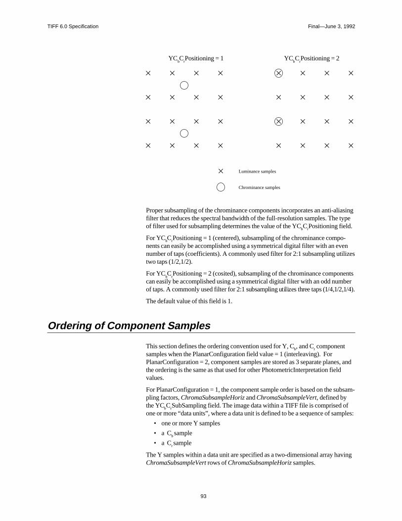
TIFF 6.0 Specification Final—June 3, 1992
liasingtype
-enlizes
entsber,1/4).
s, andd
bsam-
fmples:
ving
YCbC
rPositioning = 1 YC
bC
rPositioning = 2
Luminance samples
Chrominance samples
Proper subsampling of the chrominance components incorporates an anti-afilter that reduces the spectral bandwidth of the full-resolution samples. The of filter used for subsampling determines the value of the YCbCrPositioning field.
For YCbCrPositioning = 1 (centered), subsampling of the chrominance components can easily be accomplished using a symmetrical digital filter with an evnumber of taps (coefficients). A commonly used filter for 2:1 subsampling utitwo taps (1/2,1/2).
For YCbC
rPositioning = 2 (cosited), subsampling of the chrominance compon
can easily be accomplished using a symmetrical digital filter with an odd numof taps. A commonly used filter for 2:1 subsampling utilizes three taps (1/4,1/2
The default value of this field is 1.
Ordering of Component Samples
This section defines the ordering convention used for Y, Cb, and Cr componentsamples when the PlanarConfiguration field value = 1 (interleaving). ForPlanarConfiguration = 2, component samples are stored as 3 separate planethe ordering is the same as that used for other PhotometricInterpretation fielvalues.
For PlanarConfiguration = 1, the component sample order is based on the supling factors, ChromaSubsampleHoriz and ChromaSubsampleVert, defined bythe YCbCrSubSampling field. The image data within a TIFF file is comprised oone or more “data units”, where a data unit is defined to be a sequence of sa
• one or more Y samples
• a Cb sample
• a Cr sample
The Y samples within a data unit are specified as a two-dimensional array haChromaSubsampleVert rows of ChromaSubsampleHoriz samples.
93
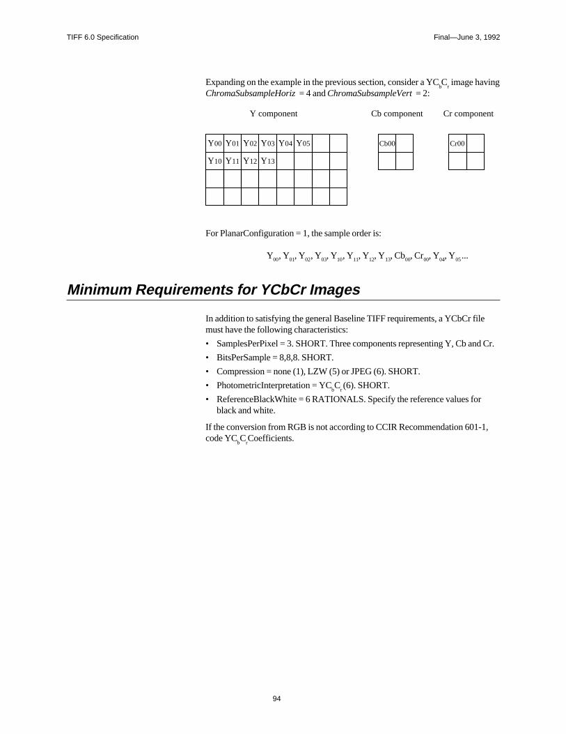
TIFF 6.0 Specification Final—June 3, 1992
d Cr.
1,
Expanding on the example in the previous section, consider a YCbC
r image having
ChromaSubsampleHoriz = 4 and ChromaSubsampleVert = 2:
Y00 Y01
Y10 Y11
Y02
Y12
Cb00 Cr00
Y component Cb component Cr component
Y05Y04
Y13
Y03
For PlanarConfiguration = 1, the sample order is:
Y00, Y01, Y02, Y03, Y10, Y11, Y12, Y13, Cb00, Cr00, Y04, Y05 ...
Minimum Requirements for YCbCr Images
In addition to satisfying the general Baseline TIFF requirements, a YCbCr filemust have the following characteristics:
• SamplesPerPixel = 3. SHORT. Three components representing Y, Cb an
• BitsPerSample = 8,8,8. SHORT.
• Compression = none (1), LZW (5) or JPEG (6). SHORT.
• PhotometricInterpretation = YCbC
r (6). SHORT.
• ReferenceBlackWhite = 6 RATIONALS. Specify the reference values forblack and white.
If the conversion from RGB is not according to CCIR Recommendation 601-code YC
bC
rCoefficients.
94
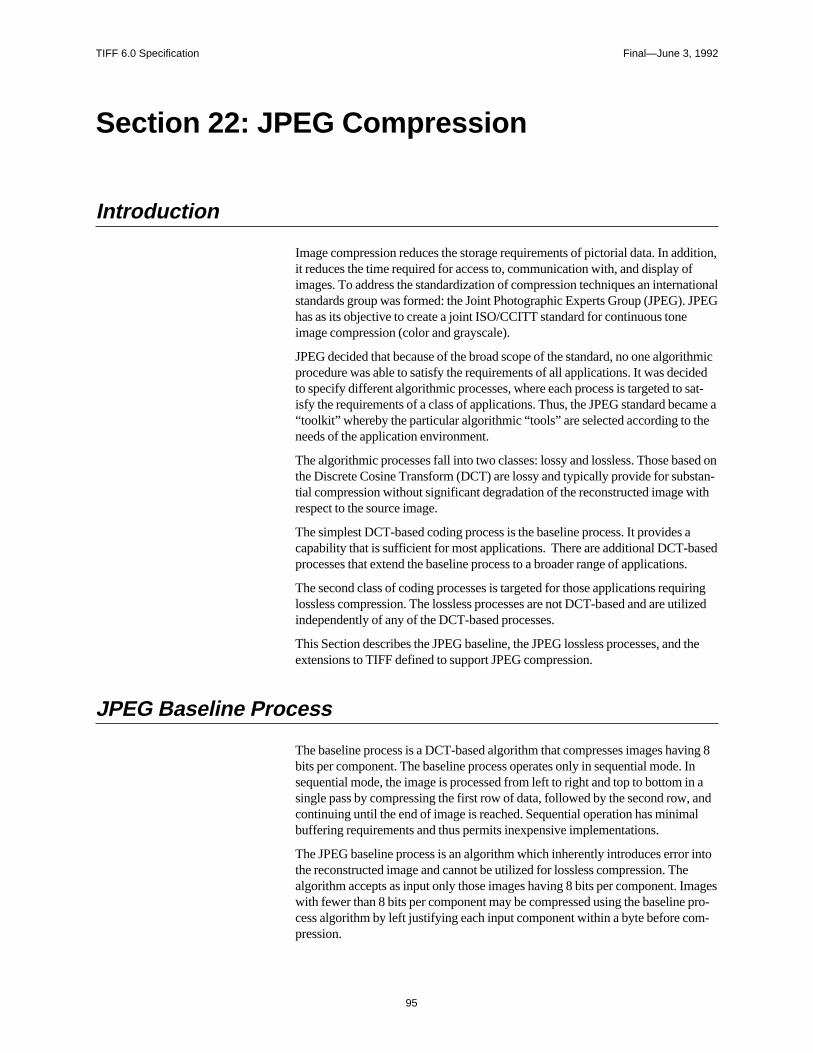
TIFF 6.0 Specification Final—June 3, 1992
dition,fational
. JPEG
rithmicided sat-came ahe
sed onstan-
ith
aaseds.
iringtilized
d the
ving 8. Inin a, andal
r intoemages pro-m-
Section 22: JPEG Compression
Introduction
Image compression reduces the storage requirements of pictorial data. In adit reduces the time required for access to, communication with, and display oimages. To address the standardization of compression techniques an internstandards group was formed: the Joint Photographic Experts Group (JPEG)has as its objective to create a joint ISO/CCITT standard for continuous toneimage compression (color and grayscale).
JPEG decided that because of the broad scope of the standard, no one algoprocedure was able to satisfy the requirements of all applications. It was decto specify different algorithmic processes, where each process is targeted toisfy the requirements of a class of applications. Thus, the JPEG standard be“toolkit” whereby the particular algorithmic “tools” are selected according to tneeds of the application environment.
The algorithmic processes fall into two classes: lossy and lossless. Those bathe Discrete Cosine Transform (DCT) are lossy and typically provide for subtial compression without significant degradation of the reconstructed image wrespect to the source image.
The simplest DCT-based coding process is the baseline process. It providescapability that is sufficient for most applications. There are additional DCT-bprocesses that extend the baseline process to a broader range of application
The second class of coding processes is targeted for those applications requlossless compression. The lossless processes are not DCT-based and are uindependently of any of the DCT-based processes.
This Section describes the JPEG baseline, the JPEG lossless processes, anextensions to TIFF defined to support JPEG compression.
JPEG Baseline Process
The baseline process is a DCT-based algorithm that compresses images habits per component. The baseline process operates only in sequential modesequential mode, the image is processed from left to right and top to bottom single pass by compressing the first row of data, followed by the second rowcontinuing until the end of image is reached. Sequential operation has minimbuffering requirements and thus permits inexpensive implementations.
The JPEG baseline process is an algorithm which inherently introduces errothe reconstructed image and cannot be utilized for lossless compression. Thalgorithm accepts as input only those images having 8 bits per component. Iwith fewer than 8 bits per component may be compressed using the baselinecess algorithm by left justifying each input component within a byte before copression.
95
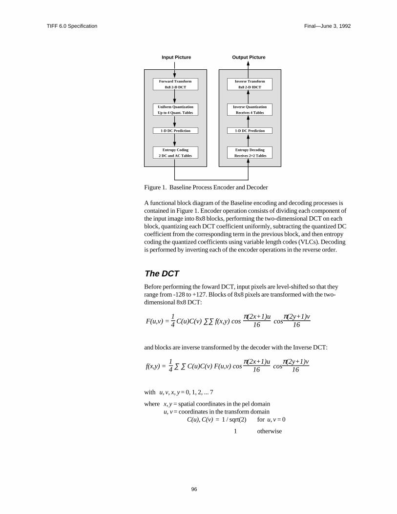
TIFF 6.0 Specification Final—June 3, 1992
s isnt ofhC
pyingr.
Entropy Coding
2 DC and AC Tables
Forward Transform
8x8 2-D DCT
Uniform Quantization
Up to 4 Quant. Tables
1-D DC Prediction
Entropy Decoding
Receives 2+2 Tables
Inverse Transform
8x8 2-D IDCT
Inverse Quantization
Receives 4 Tables
1-D DC Prediction
Input Picture Output Picture
Figure 1. Baseline Process Encoder and Decoder
A functional block diagram of the Baseline encoding and decoding processecontained in Figure 1. Encoder operation consists of dividing each componethe input image into 8x8 blocks, performing the two-dimensional DCT on eacblock, quantizing each DCT coefficient uniformly, subtracting the quantized Dcoefficient from the corresponding term in the previous block, and then entrocoding the quantized coefficients using variable length codes (VLCs). Decodis performed by inverting each of the encoder operations in the reverse orde
The DCTBefore performing the foward DCT, input pixels are level-shifted so that theyrange from -128 to +127. Blocks of 8x8 pixels are transformed with the two-dimensional 8x8 DCT:
F(u,v) = 14 C(u)C(v) ∑∑ f(x,y) cos
π(2x+1)u16 cos
π(2y+1)v16
and blocks are inverse transformed by the decoder with the Inverse DCT:
f(x,y) = 14 ∑ ∑ C(u)C(v) F(u,v) cos
π(2x+1)u16 cos
π(2y+1)v16
with u, v, x, y = 0, 1, 2, ... 7
where x, y = spatial coordinates in the pel domainu, v = coordinates in the transform domain
C(u), C(v) = 1 / sqrt(2) for u, v = 0
1 otherwise
96
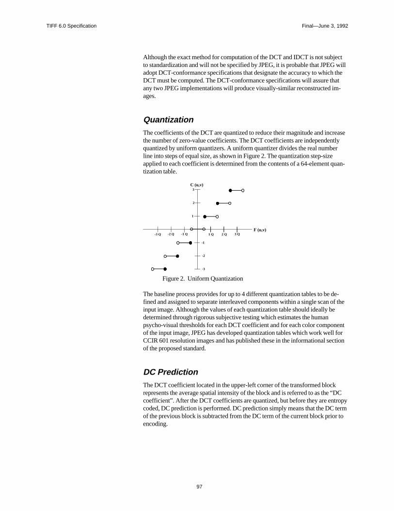
TIFF 6.0 Specification Final—June 3, 1992
ct will theat-
reasetlyr
uan-
de- of the
nentl forction
“DCropy termr to
Although the exact method for computation of the DCT and IDCT is not subjeto standardization and will not be specified by JPEG, it is probable that JPEGadopt DCT-conformance specifications that designate the accuracy to whichDCT must be computed. The DCT-conformance specifications will assure thany two JPEG implementations will produce visually-similar reconstructed images.
QuantizationThe coefficients of the DCT are quantized to reduce their magnitude and incthe number of zero-value coefficients. The DCT coefficients are independenquantized by uniform quantizers. A uniform quantizer divides the real numbeline into steps of equal size, as shown in Figure 2. The quantization step-sizeapplied to each coefficient is determined from the contents of a 64-element qtization table.
1
2
3
-1
-2
-3
1 Q 3 Q-1 Q-2 Q-3 Q
C (u,v)
F (u,v)2 Q
Figure 2. Uniform Quantization
The baseline process provides for up to 4 different quantization tables to be fined and assigned to separate interleaved components within a single scaninput image. Although the values of each quantization table should ideally bedetermined through rigorous subjective testing which estimates the humanpsycho-visual thresholds for each DCT coefficient and for each color compoof the input image, JPEG has developed quantization tables which work welCCIR 601 resolution images and has published these in the informational seof the proposed standard.
DC PredictionThe DCT coefficient located in the upper-left corner of the transformed blockrepresents the average spatial intensity of the block and is referred to as thecoefficient”. After the DCT coefficients are quantized, but before they are entcoded, DC prediction is performed. DC prediction simply means that the DCof the previous block is subtracted from the DC term of the current block prioencoding.
97
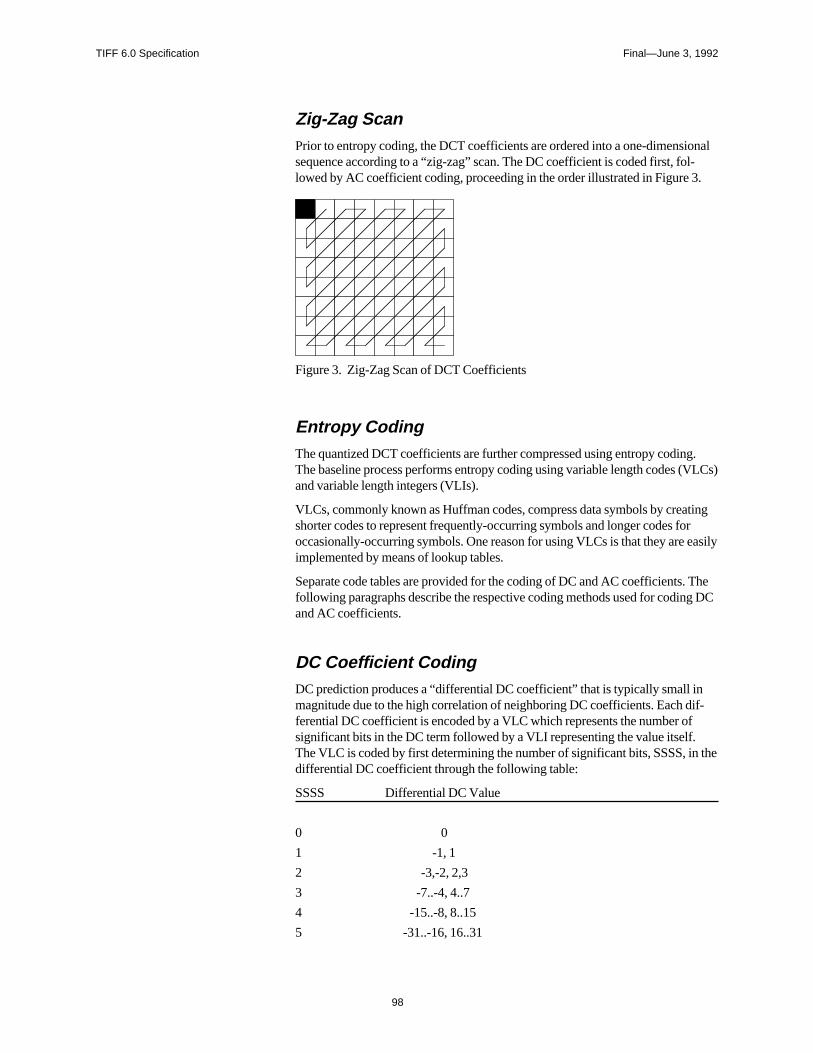
TIFF 6.0 Specification Final—June 3, 1992
onall-.
g.VLCs)
tingr
easily
Theg DC
if-f
n the
Zig-Zag ScanPrior to entropy coding, the DCT coefficients are ordered into a one-dimensisequence according to a “zig-zag” scan. The DC coefficient is coded first, folowed by AC coefficient coding, proceeding in the order illustrated in Figure 3
Figure 3. Zig-Zag Scan of DCT Coefficients
Entropy CodingThe quantized DCT coefficients are further compressed using entropy codinThe baseline process performs entropy coding using variable length codes (and variable length integers (VLIs).
VLCs, commonly known as Huffman codes, compress data symbols by creashorter codes to represent frequently-occurring symbols and longer codes fooccasionally-occurring symbols. One reason for using VLCs is that they are implemented by means of lookup tables.
Separate code tables are provided for the coding of DC and AC coefficients.following paragraphs describe the respective coding methods used for codinand AC coefficients.
DC Coefficient CodingDC prediction produces a “differential DC coefficient” that is typically small inmagnitude due to the high correlation of neighboring DC coefficients. Each dferential DC coefficient is encoded by a VLC which represents the number osignificant bits in the DC term followed by a VLI representing the value itself.The VLC is coded by first determining the number of significant bits, SSSS, idifferential DC coefficient through the following table:
SSSS Differential DC Value
0 0
1 -1, 1
2 -3,-2, 2,3
3 -7..-4, 4..7
4 -15..-8, 8..15
5 -31..-16, 16..31
98
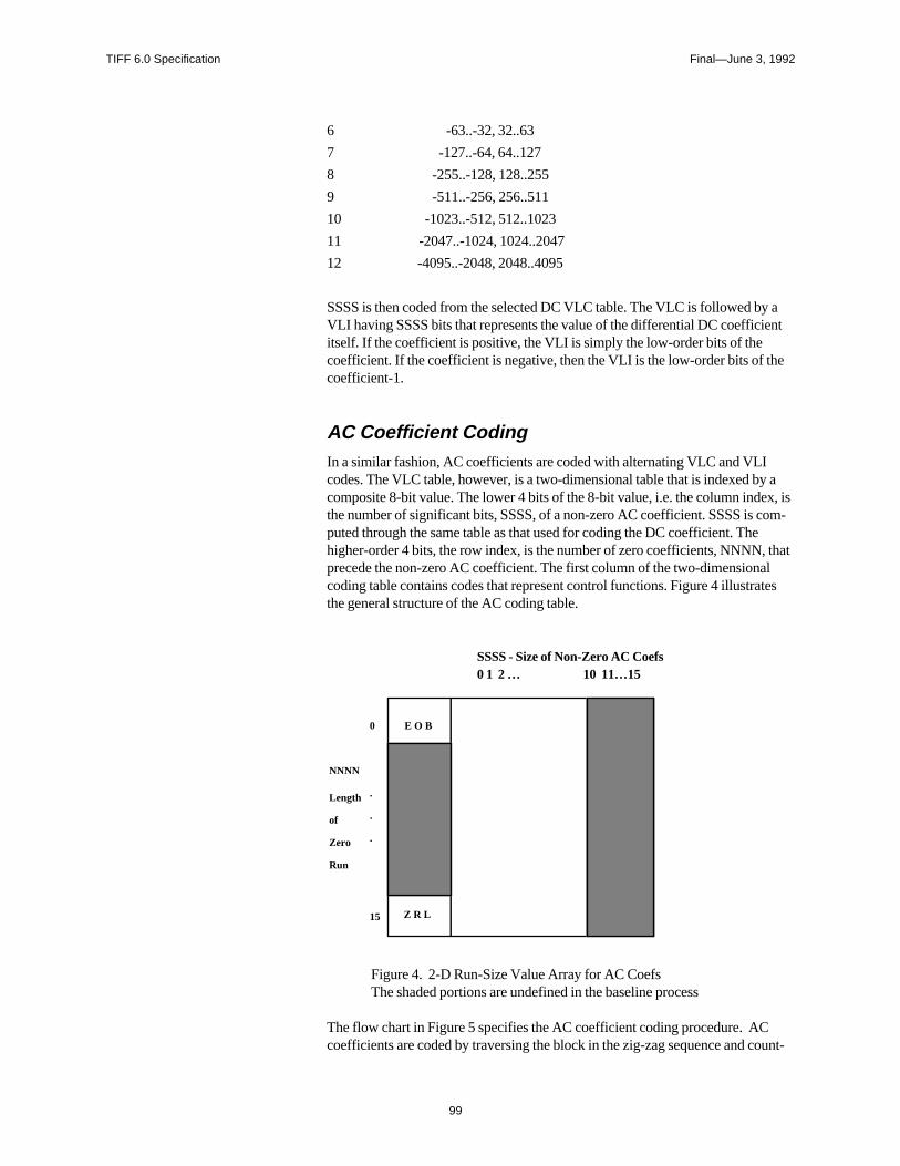
TIFF 6.0 Specification Final—June 3, 1992
aent
he
y ax, isom-
thatltes
ount-
6 -63..-32, 32..63
7 -127..-64, 64..127
8 -255..-128, 128..255
9 -511..-256, 256..511
10 -1023..-512, 512..1023
11 -2047..-1024, 1024..2047
12 -4095..-2048, 2048..4095
SSSS is then coded from the selected DC VLC table. The VLC is followed byVLI having SSSS bits that represents the value of the differential DC coefficiitself. If the coefficient is positive, the VLI is simply the low-order bits of thecoefficient. If the coefficient is negative, then the VLI is the low-order bits of tcoefficient-1.
AC Coefficient CodingIn a similar fashion, AC coefficients are coded with alternating VLC and VLIcodes. The VLC table, however, is a two-dimensional table that is indexed bcomposite 8-bit value. The lower 4 bits of the 8-bit value, i.e. the column indethe number of significant bits, SSSS, of a non-zero AC coefficient. SSSS is cputed through the same table as that used for coding the DC coefficient. Thehigher-order 4 bits, the row index, is the number of zero coefficients, NNNN,precede the non-zero AC coefficient. The first column of the two-dimensionacoding table contains codes that represent control functions. Figure 4 illustrathe general structure of the AC coding table.
SSSS - Size of Non-Zero AC Coefs0 1 2 … 10 11…15
E O B
Z R L
0
.
.
.
15
NNNN
of
Zero
Run
Length
Figure 4. 2-D Run-Size Value Array for AC CoefsThe shaded portions are undefined in the baseline process
The flow chart in Figure 5 specifies the AC coefficient coding procedure. ACcoefficients are coded by traversing the block in the zig-zag sequence and c
99
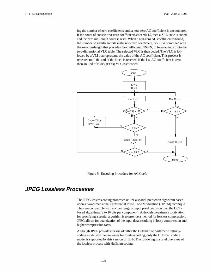
TIFF 6.0 Specification Final—June 3, 1992
ered.codednd, witho the
so,
sedue.-ionsion,n and
gof
ing the number of zero coefficients until a non-zero AC coefficient is encountIf the count of consecutive zero coefficients exceeds 15, then a ZRL code is and the zero run-length count is reset. When a non-zero AC coefficient is fouthe number of significant bits in the non-zero coefficient, SSSS, is combinedthe zero run-length that precedes the coefficient, NNNN, to form an index inttwo-dimensional VLC table. The selected VLC is then coded. The VLC is fol-lowed by a VLI that represents the value of the AC coefficient. This process irepeated until the end of the block is reached. If the last AC coefficient is zerthen an End of Block (EOB) VLC is encoded.
K = 0R = 0
K = K + 1 R = R + 1
K = 63 ?
R > 15 ?
Code R,Coef (K)R = 0
K = 63 ?
Start
Code (EOB)
Code (ZRL)R = R - 16
Y
N
N
N
N
Y
Y
Y
Coef(K) = 0?
Done
Figure 5. Encoding Procedure for AC Coefs
JPEG Lossless Processes
The JPEG lossless coding processes utilize a spatial-prediction algorithm baupon a two-dimensional Differential Pulse Code Modulation (DPCM) techniqThey are compatible with a wider range of input pixel precision than the DCTbased algorithms (2 to 16 bits per component). Although the primary motivatfor specifying a spatial algorithm is to provide a method for lossless compresJPEG allows for quantization of the input data, resulting in lossy compressiohigher compression rates.
Although JPEG provides for use of either the Huffman or Arithmetic entropy-coding models by the processes for lossless coding, only the Huffman codinmodel is supported by this version of TIFF. The following is a brief overview the lossless process with Huffman coding.
100
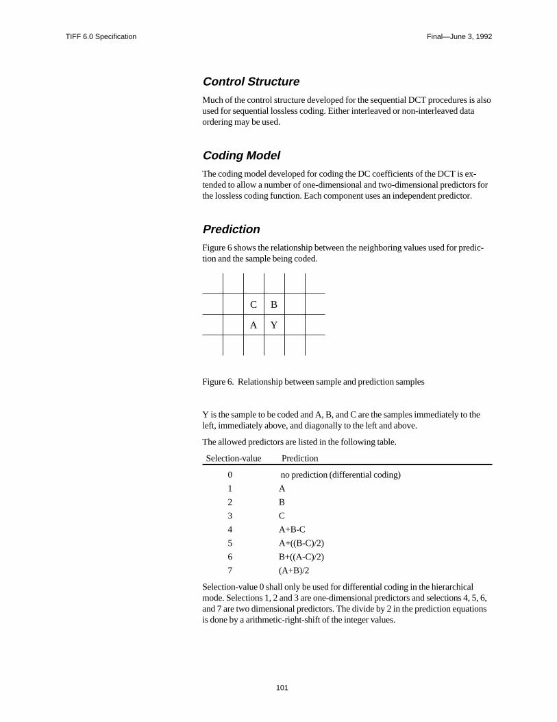
TIFF 6.0 Specification Final—June 3, 1992
s alsota
-s forr.
dic-
the
, 5, 6,ions
Control StructureMuch of the control structure developed for the sequential DCT procedures iused for sequential lossless coding. Either interleaved or non-interleaved daordering may be used.
Coding ModelThe coding model developed for coding the DC coefficients of the DCT is extended to allow a number of one-dimensional and two-dimensional predictorthe lossless coding function. Each component uses an independent predicto
PredictionFigure 6 shows the relationship between the neighboring values used for pretion and the sample being coded.
C B
A Y
Figure 6. Relationship between sample and prediction samples
Y is the sample to be coded and A, B, and C are the samples immediately toleft, immediately above, and diagonally to the left and above.
The allowed predictors are listed in the following table.
Selection-value Prediction
0 no prediction (differential coding)
1 A
2 B
3 C
4 A+B-C
5 A+((B-C)/2)
6 B+((A-C)/2)
7 (A+B)/2
Selection-value 0 shall only be used for differential coding in the hierarchicalmode. Selections 1, 2 and 3 are one-dimensional predictors and selections 4and 7 are two dimensional predictors. The divide by 2 in the prediction equatis done by a arithmetic-right-shift of the integer values.
101
TIFF 6.0 Specification Final—June 3, 1992
ulo. In
iction.
sed 17
edrma-.
a-d byofhe
ssary
n.)
on.)
sed to a toling
m-ncor-
The difference between the prediction value and the input is calculated mod2**16. Therefore, the prediction can also be treated as a modulo 2**16 valuethe decoder the difference is decoded and added, modulo 2**16, to the pred
Huffman Coding of the Prediction ErrorThe Huffman coding procedures defined for coding the DC coefficients are uto code the modulo 2**16 differences. The table for DC coding is extended toentries that allows for coding of the modulo 2**16 differences.
Point Transformation Prior to Lossless CodingFor the lossless processes only, the input image data may optionally be scal(quantized) prior to coding by specifying a nonzero value in the point transfotion parameter. Point transformation is defined to be division by a power of 2
If the point transformation field is nonzero for a component, a point transformtion of the input is performed prior to the lossless coding. The input is divide2**Pt, where Pt is the value of the point transform signaling field. The output the decoder is rescaled to the input range by multiplying by 2**Pt. Note that tscaling of input and output can be performed by arithmetic shifts.
Overview of the JPEG Extension to TIFF
In extending the TIFF definition to include JPEG compressed data, it is neceto note the following:
• JPEG is effective only on continuous-tone color spaces:
Grayscale (Photometric Interpretation = 1)
RGB (Photometric Interpretation = 2)
CMYK (Photometric Interpretation = 5) (See the CMYK Images sectio
YCbCr (Photometric Interpretation = 6) (See the YCbCr images secti
• Color conversion to YCbCr is often used as part of the compression processbecause the chrominance components can be subsampled and compresgreater degree without significant visual loss of quality. Fields are defineddescribe how this conversion has taken place and the degree of subsampemployed (see the YCbCr Images section).
• New fields have been defined to specify the JPEG parameters used for copression and to allow quantization tables and Huffman code tables to be iporated into the TIFF file.
102
TIFF 6.0 Specification Final—June 3, 1992
ax ofed
at.
T-han
. Theeinhe
the
n:
isting
at cangeressedy
artata,tartrvaloff-p or
• TIFF is compatible with compressed image data that conforms to the syntthe JPEG interchange format for compressed image data. Fields are definthat may be utilized to facilitate conversion from TIFF to interchange form
• The PlanarConfiguration Field is used to specify whether or not the com-pressed data is interleaved as defined by JPEG. For any of the JPEG DCbased processes, the interleaved data units are coded 8x8 blocks rather tcomponent samples.
• Although JPEG codes consecutive image blocks in a single contiguousbitstream, it is extremely useful to employ the concept of tiles in an imageTIFF Tiles section defines some new fields for tiles. These fields should bstored in place of the older fields for strips. The concept of tiling an image both dimensions is important because JPEG hardware may be limited in tsize of each block that is handled.
• Note that the nomenclature used in the TIFF specification is different fromJPEG Draft International Standardittee Draft (ISO DIS 10918-1) in somerespects. The following terms should be equated when reading this Sectio
TIFF name JPEG DIS name
ImageWidth Number of Pixels
ImageLength Number of Lines
SamplesPerPixel Number of Components
JPEGQTable Quantization Table
JPEGDCTable Huffman Table for DC coefficients
JPEGACTable Huffman Table for AC coefficients
Strips and Tiles
The JPEG extension to TIFF has been designed to be consistent with the exTIFF strip and tile structures and to allow quick conversion to and from thestream-oriented compressed image format defined by JPEG.
Compressed images conforming to the syntax of the JPEG interchange formbe converted to TIFF simply by defining a single strip or tile for the entire imaand then concatenating the TIFF image description fields to the JPEG compimage data. The strip or tile offset field points directly to the start of the entropcoded data (not to a JPEG marker).
Multiple strips or tiles are supported in JPEG compressed images using restmarkers. Restart markers, inserted periodically into the compressed image ddelineate image segments known as restart intervals. At the start of each resinterval, the coding state is reset to default values, allowing every restart inteto be decoded independently of previously decoded data. TIFF strip and tile sets shall always point to the start of a restart interval. Equivalently, each stri
103
TIFF 6.0 Specification Final—June 3, 1992
t be.
isrm-en
eight
mat
. Theon
les
e-
tile contains an integral number of restart intervals. Restart markers need nopresent in a TIFF file; they are implicitly coded at the start of every strip or tile
To maximize interchangeability of TIFF files with other formats, a restriction placed on tile height for files containing JPEG-compressed image data confoing to the JPEG interchange format syntax. The restriction, imposed only whthe tile width is shorter than the image width and when theJPEGInterchangeFormat Field is present and non-zero, states that the tile hmust be equal to the height of one JPEG Minimum Coded Unit (MCU). Thisrestriction ensures that TIFF files may be converted to JPEG interchange forwithout undergoing decompression.
Extensions to Existing Fields
CompressionTag = 259 (103.H)
Type = SHORT
N = 1
This Field indicates the type of compression used. The new value is:
6 = JPEG
JPEG Fields
JPEGProcTag = 512 (200.H)
Type = SHORT
N = 1
This Field indicates the JPEG process used to produce the compressed datavalues for this field are defined to be consistent with the numbering conventiused in ISO DIS 10918-2. Two values are defined at this time.
1= Baseline sequential process
14= Lossless process with Huffman coding
When the lossless process with Huffman coding is selected by this Field, theHuffman tables used to encode the image are specified by the JPEGDCTabfield, and the JPEGACTables field is not used.
Values indicating JPEG processes other than those specified above will be dfined in the future.
104

TIFF 6.0 Specification Final—June 3, 1992
sble
lt).
t in theoints
t
eam.out
is
Not all of the fields described in this section are relevant to the JPEG processelected by this Field. The following table specifies the fields that are applicato each value defined by this Field.
Tag Name JPEGProc =1 JPEGProc =14
JPEGInterchangeFormat X X
JPEGInterchangeFormatLength X X
JPEGRestart Interval X X
JPEGLosslessPredictors X
JPEGPointTransforms X
JPEGQTables X
JPEGDCTables X X
JPEGACTables X
This Field is mandatory whenever the Compression Field is JPEG (no defau
JPEGInterchangeFormatTag = 513 (201.H)
Type = LONG
N = 1
This Field indicates whether a JPEG interchange format bitstream is presenTIFF file. If a JPEG interchange format bitstream is present, then this Field pto the Start of Image (SOI) marker code.
If this Field is zero or not present, a JPEG interchange format bitstream is nopresent.
JPEGInterchangeFormatLengthTag = 514 (202.H)
Type = LONG
N = 1
This Field indicates the length in bytes of the JPEG interchange format bitstrThis Field is useful for extracting the JPEG interchange format bitstream withparsing the bitstream.
This Field is relevant only if the JPEGInterchangeFormat Field is present andnon-zero.
JPEGRestartIntervalTag = 515 (203.H)
Type = SHORT
N = 1
105

TIFF 6.0 Specification Final—June 3, 1992
image
rreset oftart
er of im-
ma-
start
o-
ils.
This Field indicates the length of the restart interval used in the compressed data. The restart interval is defined as the number of Minimum Coded Units(MCUs) between restart markers.
Restart intervals are used in JPEG compressed images to provide support fomultiple strips or tiles. At the start of each restart interval, the coding state is to default values, allowing every restart interval to be decoded independentlypreviously decoded data. TIFF strip and tile offsets shall always point to the sof a restart interval. Equivalently, each strip or tile contains an integral numbrestart intervals. Restart markers need not be present in a TIFF file; they areplicitly coded at the start of every strip or tile.
See the JPEG Draft International Standard (ISO DIS 10918-1) for more infortion about the restart interval and restart markers.
If this Field is zero or is not present, the compressed data does not contain remarkers.
JPEGLosslessPredictorsTag = 517 (205.H)
Type = SHORT
N = SamplesPerPixel
This Field points to a list of lossless predictor-selection values, one per compnent.The allowed predictors are listed in the following table.
Selection-value Prediction
1 A
2 B
3 C
4 A+B-C
5 A+((B-C)/2)
6 B+((A-C)/2)
7 (A+B)/2
A, B, and C are the samples immediately to the left, immediately above, anddiagonally to the left and above the sample to be coded, respectively.
See the JPEG Draft International Standard (ISO DIS 10918-1) for more deta
This Field is mandatory whenever the JPEGProc Field specifies one of thelossless processes (no default).
JPEGPointTransformsTag = 518 (206.H)
Type = SHORT
N = SamplesPerPixel
106
TIFF 6.0 Specification Final—June 3, 1992
Field
ma- bycaled
ils.
nent.ock).
ils.
ignedifies a
6;
ils.
igned.
This Field points to a list of point transform values, one per component. This is relevant only for lossless processes.
If the point transformation value is nonzero for a component, a point transfortion of the input is performed prior to the lossless coding. The input is divided2**Pt, where Pt is the point transform value. The output of the decoder is resto the input range by multiplying by 2**Pt. Note that the scaling of input andoutput can be performed by arithmetic shifts.
See the JPEG Draft International Standard (ISO DIS 10918-1) for more detaThe default value of this Field is 0 for each component (no scaling).
JPEGQTablesTag = 519 (207.H)
Type = LONG
N = SamplesPerPixel
This Field points to a list of offsets to the quantization tables, one per compoEach table consists of 64 BYTES (one for each DCT coefficient in the 8x8 blThe quantization tables are stored in zigzag order.
See the JPEG Draft International Standard (ISO DIS 10918-1) for more deta
It is strongly recommended that, within the TIFF file, each component be assseparate tables. This Field is mandatory whenever the JPEGProc Field specDCT-based process (no default).
JPEGDCTablesTag = 520 (208.H)
Type = LONG
N = SamplesPerPixel
This Field points to a list of offsets to the DC Huffman tables or the losslessHuffman tables, one per component.
The format of each table is as follows:
16 BYTES of “BITS”, indicating the number of codes of lengths 1 to 1
Up to 17 BYTES of “VALUES”, indicating the values associated withthose codes, in order of length.
See the JPEG Draft International Standard (ISO DIS 10918-1) for more deta
It is strongly recommended that, within the TIFF file, each component be assseparate tables. This Field is mandatory for all JPEG processes (no default)
JPEGACTablesTag = 521 (209.H)
Type = LONG
N = SamplesPerPixel
107
TIFF 6.0 Specification Final—June 3, 1992
nent.
6;
ils.
ignedifies a
This Field points to a list of offsets to the Huffman AC tables, one per compoThe format of each table is as follows:
16 BYTES of “BITS”, indicating the number of codes of lengths 1 to 1
Up to 256 BYTES of “VALUES”, indicating the values associated withthose codes, in order of length.
See the JPEG Draft International Standard (ISO DIS 10918-1) for more deta
It is strongly recommended that, within the TIFF file, each component be assseparate tables. This Field is mandatory whenever the JPEGProc Field specDCT-based process (no default).
108

TIFF 6.0 Specification Final—June 3, 1992
filess.
,
ne
Minimum Requirements for TIFF with JPEG Compression
The table on the following page shows the minimum requirements of a TIFF that uses tiling and contains JPEG data compressed with the Baseline proce
Tag = NewSubFileType (254)Type = LongLength = 1Value = 0
Single image
Tag = ImageWidth (256)Type = LongLength = 1Value = ?
Tag = ImageLength (257)Type = LongLength = 1Value = ?
Tag = BitsPerSample (258)Type = ShortLength = SamplesPerPixelValue = ?
8 : Monochrome8,8,8 : RGB8,8,8 : YCbCr 8,8,8,8 : CMYK
Tag = Compression (259)Type = LongLength = 1Value = 6
6 : JPEG compression
Tag = PhotometricInterpretation (262)Type = ShortLength = 1Value = ?
0,1 : Monochrome2 : RGB5 : CMYK6 : YCbCr
Tag = SamplesPerPixel (277)Type = ShortLength = 1Value = ?
1 : Monochrome3 : RGB3 : YCbCr4 : CMYK
Tag = XResolution (282)Type = RationalLength = 1Value = ?
Tag = YResolution (283)Type = RationalLength = 1Value = ?
Tag = PlanarConfiguration (284)Type = ShortLength = 1Value = ?
1 : Block Interleaved2 : Not interleaved
Tag = ResolutionUnit (296)Type = ShortLength = 1Value = ?
Tag = TileWidth (322)Type = ShortLength = 1Value = ?
Multiple of 8
Tag = TileLength (323)Type = ShortLength = 1Value = ?
Multiple of 8
Tag = TileOffsets (324)Type = LongLength = Number of tilesValue = ?
Tag = TileByteCounts (325)Type = LongLength = Number of tilesValue = ?
Tag = JPEGProc (512)Type = ShortLength = 1Value = ?
1 : Baseline process
Tag = JPEGQTables (519)Type = LongLength = SamplesPerPixelValue = ?
Offsets to tables
Tag = JPEGDCTables (520)Type = LongLength = SamplesPerPixelValue = ?
Offsets to tables
Tag = JPEGACTables (521)Type = LongLength = SamplesPerPixelValue = ?
Offsets to tables
References
[1] Wallace, G., “Overview of the JPEG Still Picture Compression Algorithm”Electronic Imaging East ’90.
[2] ISO/IEC DIS 10918-1, “Digital Compression and Coding of Continuous-toStill Images”, Sept. 1991.
109
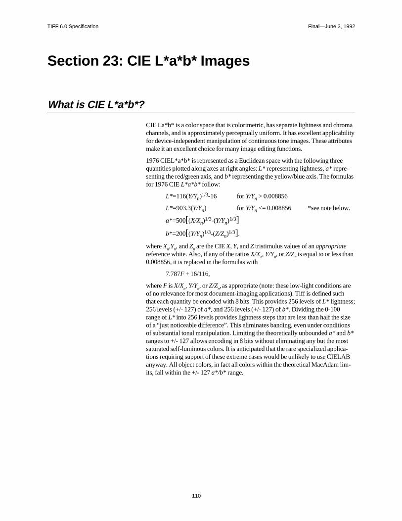
TIFF 6.0 Specification Final—June 3, 1992
romabilitybutes
as
reh
sizeons
stica-AB-
Section 23: CIE L*a*b* Images
What is CIE L*a*b*?
CIE La*b* is a color space that is colorimetric, has separate lightness and chchannels, and is approximately perceptually uniform. It has excellent applicafor device-independent manipulation of continuous tone images. These attrimake it an excellent choice for many image editing functions.
1976 CIEL*a*b* is represented as a Euclidean space with the following threequantities plotted along axes at right angles: L* representing lightness, a* repre-senting the red/green axis, and b* representing the yellow/blue axis. The formulfor 1976 CIE L*a*b* follow:
L*=116(Y/Yn)1/3-16 for Y/Yn > 0.008856
L*=903.3(Y/Yn) for Y/Yn <= 0.008856 *see note below.
a*=500[(X/Xn)1/3-(Y/Yn)
1/3]
b*=200[(Y/Yn)1/3-(Z/Zn)
1/3].
where Xn,Yn, and Zn are the CIE X, Y, and Z tristimulus values of an appropriatereference white. Also, if any of the ratios X/Xn, Y/Yn, or Z/Zn is equal to or less than0.008856, it is replaced in the formulas with
7.787F + 16/116,
where F is X/Xn, Y/Yn, or Z/Zn, as appropriate (note: these low-light conditions aof no relevance for most document-imaging applications). Tiff is defined sucthat each quantity be encoded with 8 bits. This provides 256 levels of L* lightness;256 levels (+/- 127) of a*, and 256 levels (+/- 127) of b*. Dividing the 0-100range of L* into 256 levels provides lightness steps that are less than half theof a “just noticeable difference”. This eliminates banding, even under conditiof substantial tonal manipulation. Limiting the theoretically unbounded a* and b*ranges to +/- 127 allows encoding in 8 bits without eliminating any but the mosaturated self-luminous colors. It is anticipated that the rare specialized appltions requiring support of these extreme cases would be unlikely to use CIELanyway. All object colors, in fact all colors within the theoretical MacAdam limits, fall within the +/- 127 a*/b* range.
110

TIFF 6.0 Specification Final—June 3, 1992
r the
will
on
The TIFF CIELAB Fields
PhotometricInterpretationTag = 262 (106.H)
Type = SHORT
N = 1
8 = 1976 CIE L*a*b*
Usage of other Fields.BitsPerSample: 8
SamplesPerPixel - ExtraSamples: 3 for L*a*b* , 1 implies L* only, for mono-chrome data.
Compression: same as other multi-bit formats. JPEG compression applies.
PlanarConfiguration: both chunky and planar data could be supported.
WhitePoint: does not apply
PrimaryChromaticities: does not apply.
TransferFunction: does not apply
Alpha Channel information will follow the lead of other data types.
The reference white for this data type is the perfect reflecting diffuser (100%diffuse reflectance at all visible wavelengths). The L* range is from 0 (perfectabsorbing black) to 100 (perfect reflecting diffuse white). The a* and b* rangeswill be represented as signed 8 bit values having the range -127 to +127.
Converting between RGB and CIELAB, a Caveat
The above CIELAB formulae are derived from CIE XYZ. Converting fromCIELAB to RGB requires an additional set of formulae for converting betweenRGB and XYZ. For standard NTSC primaries these are:
0.60700.17400.2000 R X
0.29900.58700.1140 * G = Y
0.00000.06601.1110 B Z
Generally, D65 illumination is used and a perfect reflecting diffuser is used foreference white.
Since CIELAB is not a directly displayable format, some conversion to RGB be required. While look-up table accelerated CIELAB to RGB conversion iscertainly possible and fast, TIFF writers may choose to include a low resolutiRGB subfile as an integral part of TIFF CIELAB.
111

TIFF 6.0 Specification Final—June 3, 1992
ted
e:
if-
e can
t hasgved
ly-es
Col-ing areh-
e or
Color Difference Measurements in CIELABThe differences between two colors in L*, a*, and b* are denoted by DL*, Da*,and Db*, respectively, with the total (3-dimensional) color difference represenas:
∆E*ab = [(∆E*) 2+(∆a*)2+(∆b*)2]1/2.
This color difference can also be expressed in terms of L*, C*, and a measure ofhue. In this case, h
ab is not used because it is an angular measure and cannot b
combined with L* and C* directly. A linear-distance form of hue is used instead
CIE 1976 a,b hue-difference, ∆H*ab
∆H*ab = [(∆E*) 2-(∆L* )2-(∆C*)2]1/2.
where DC* is the chroma difference between the two colors. The total color dference expression using this hue-difference is:
∆E*ab = [(∆L*)2+(∆H*)2+(∆b*)2]1/2.
It is important to remember that color difference is 3-dimensional: much morbe learned from a DL*a*b* triplet than from a single DE value. The DL*C*H*form is often the most useful since it gives the error information in a form thamore familiar perception correlates. Caution is in order, however, when usinDH* for large hue differences since it is a straight-line approximation of a curhue distance.
The Merits of CIELAB
Colorimetric.First and foremost, CIELAB is colorimetric. It is traceable to the internationalrecognized standard CIE 1931 Standard Observer. This insures that it encodcolor in a manner that is accurately modeled after the human vision system. ors seen as matching are encoded identically, and colors seen as not matchencoded differently. CIELAB provides an unambiguous definition of color witout the necessity of additional information such as with RGB (primarychromaticities, white point, and gamma curves).
Device Independent.Unlike RGB spaces which associate closely with physical phosphor colors,CIELAB contains no device association. CIELAB is not tailored for one devicdevice type at the expense of all others.
112
TIFF 6.0 Specification Final—June 3, 1992
f theesolorvis-mut is
lf andat-tagesre note, large
ani-
sELABndard.
aratedegree
tnd
andsuch a this
,d-
Full Color Gamut.Any one image or imaging device usually encounters a very limited subset oentire range of humanly-perceptible color. Collectively, however, these imagand devices span a much larger gamut of color. A truly versatile exchange cspace should encompass all of these colors, ideally providing support for all ible color. RGB, PhotoYCC, YCbCr, and other display spaces suffer from galimitations that exclude significant regions of easily printable colors. CIELABdefined for all visible color.
EfficiencyA good exchange space will maximize accuracy of translations between itseother spaces. It will represent colors compactly for a given accuracy. These tributes are provided through visual uniformity. One of the greatest disadvanof the classic CIE system (and RGB systems as well) is that colors within it aequally spaced visually. Encoding full-color images in a linear-intensity spacsuch as the typical RGB space or, especially, the XYZ space, requires a veryrange (greater than 8-bits/primary) to eliminate banding artifacts. Adopting anon-linear RGB space improves the efficiency but not nearly to the extent as withperceptually uniform space where these problems are nearly eliminated. A uform space is also more efficiently compressed (see below).
Public Domain / Single StandardCIELAB maintains no preferential attachments to any private organization. Itexistence as a single standard leaves no room for ambiguity. Since 1976, CIhas continually gained popularity as a widely-accepted and heavily-used sta
Luminance/Chrominance Separation.The advantages for image size compression made possible by having a seplightness or luminance channel are immense. Many such spaces exist. The to which the luminance information is fully-isolated into a single channel is animportant consideration. Recent studies (Kasson and Plouffe of IBM) supporCIELAB as a leading candidate placing it above CIELUV, YIQ, YUV, YCC, aXYZ.
Other advantages support a separate lightness or luminance channel. Tonecontrast editing and detail enhancement are most easily accomplished with channel. Conversion to a black and white representation is also easiest withtype of space.
When the chrominance channels are encoded as opponents as with CIELABthere are other compression, image manipulation, and white point handling avantages.
113
TIFF 6.0 Specification Final—June 3, 1992
m-s con-nd
d-
is a
ctlytice-
ith
he
aceope ofksn-
eally
ask-irtsely,e that ad-
a
ired
Compressibility (Data).Opponent spaces such as CIELAB are inherently more compressible thantristimulus spaces such as RGB. The chroma content of an image can be copressed to a greater extent, without objectionable loss, than can the lightnestent. The opponent arrangement of CIELAB allows for spatial subsampling aefficent compression using JPEG.
Compressibility (Gamut).Adjusting the color range of an image to match the capabilities of the intendeoutput device is a critical function within computational color reproduction. Luminance/chrominance separation, especially when provided in a polar form,desirable for facilitating gamut compression. Accurate gamut compression intri-linear color space is difficult.
CIELAB has a polar form (metric hue angle, and metric chroma, described be-low) that serves compression needs fairly well. Because CIELAB is not perfeuniform, problems can arise when compressing along constant hue lines. Noable hue errors are sometimes introduced. This problem is no less severe wother contending color spaces.
This polar form also provides advantages for local color editing of images. Tpolar form is not proposed as part of the TIFF addition.
Getting the Most from CIELAB
Image EditorsThe advantages of image editing within a perceptually uniform polar color spare tremendous. A detailed description of these advantages is beyond the scthis section. As previously mentioned, many common tonal manipulation tasare most efficiently performed when only a single channel is affected. Edge ehancement, contrast adjustment, and general tone-curve manipulation all idaffect only the lightness component of an image.
A perceptual polar space works excellently for specifying a color range for ming purposes. For example, a red shirt can be quickly changed to a green shwithout drawing an outline mask. The operation can be performed with a looquickly-drawn mask region combined with a hue (and perhaps chroma) rangencompasses the shirt’s colors. The hue component of the shirt can then bejusted, leaving the lightness and chroma detail in place.
Color cast adjustment is easily realized by shifting either or both of the chromchannels over the entire image or blending them over the region of interest.
Converting from CIELAB to a device specific spaceFor fast conversion to an RGB display, CIELAB can be decoded using 3x3matrixing followed by gamma correction. The computational complexity requ
114

TIFF 6.0 Specification Final—June 3, 1992
ce-
a--s for
for accurate CRT display is the same with CIELAB as with extended luminanchrominance spaces.
Converting CIELAB for accurate printing on CMYK devices requires computtional complexity no greater than with accurate conversion from any other colorimetric space. Gamut compression becomes one of the more significant taskany such conversion.
115
TIFF 6.0 Specification Final—June 3, 1992
,
Part 3: AppendicesPart 3 contains additional information that is not part of the TIFF specificationbut may be of use to developers.
116
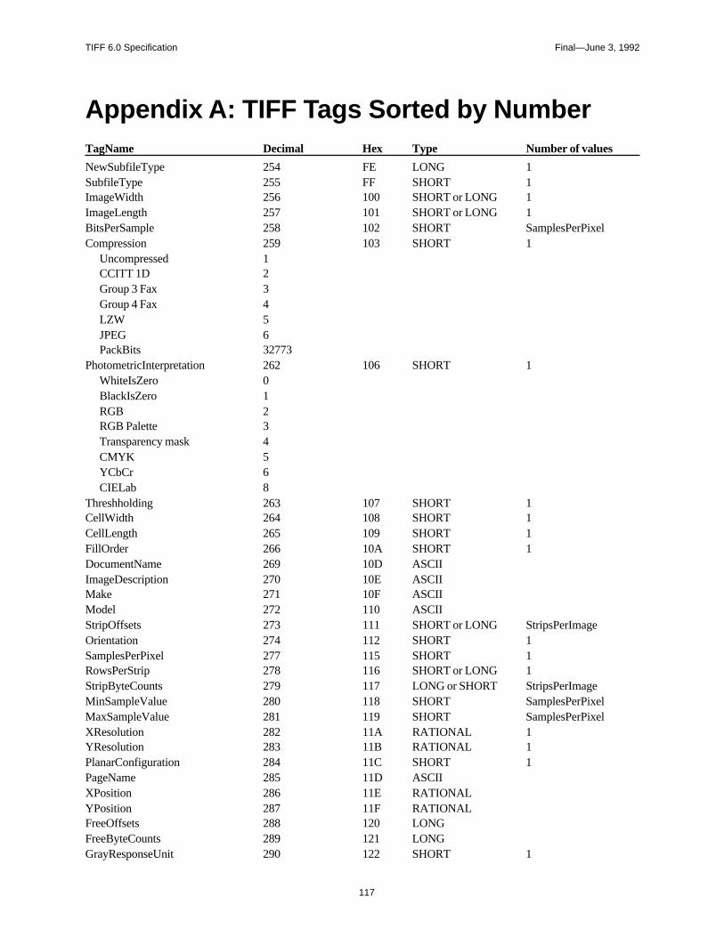
TIFF 6.0 Specification Final—June 3, 1992
Appendix A: TIFF Tags Sorted by NumberTagName Decimal Hex Type Number of values
NewSubfileType 254 FE LONG 1SubfileType 255 FF SHORT 1ImageWidth 256 100 SHORT or LONG 1ImageLength 257 101 SHORT or LONG 1BitsPerSample 258 102 SHORT SamplesPerPixelCompression 259 103 SHORT 1
Uncompressed 1CCITT 1D 2Group 3 Fax 3Group 4 Fax 4LZW 5JPEG 6PackBits 32773
PhotometricInterpretation 262 106 SHORT 1WhiteIsZero 0BlackIsZero 1RGB 2RGB Palette 3Transparency mask 4CMYK 5YCbCr 6CIELab 8
Threshholding 263 107 SHORT 1CellWidth 264 108 SHORT 1CellLength 265 109 SHORT 1FillOrder 266 10A SHORT 1DocumentName 269 10D ASCIIImageDescription 270 10E ASCIIMake 271 10F ASCIIModel 272 110 ASCIIStripOffsets 273 111 SHORT or LONG StripsPerImageOrientation 274 112 SHORT 1SamplesPerPixel 277 115 SHORT 1RowsPerStrip 278 116 SHORT or LONG 1StripByteCounts 279 117 LONG or SHORT StripsPerImageMinSampleValue 280 118 SHORT SamplesPerPixelMaxSampleValue 281 119 SHORT SamplesPerPixelXResolution 282 11A RATIONAL 1YResolution 283 11B RATIONAL 1PlanarConfiguration 284 11C SHORT 1PageName 285 11D ASCIIXPosition 286 11E RATIONALYPosition 287 11F RATIONALFreeOffsets 288 120 LONGFreeByteCounts 289 121 LONGGrayResponseUnit 290 122 SHORT 1
117
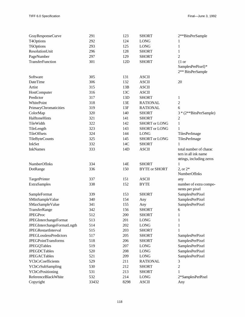
TIFF 6.0 Specification Final—June 3, 1992
)
o-
GrayResponseCurve 291 123 SHORT 2**BitsPerSampleT4Options 292 124 LONG 1T6Options 293 125 LONG 1ResolutionUnit 296 128 SHORT 1PageNumber 297 129 SHORT 2TransferFunction 301 12D SHORT 1 or
SamplesPerPixel*2** BitsPerSample
Software 305 131 ASCIIDateTime 306 132 ASCII 20Artist 315 13B ASCIIHostComputer 316 13C ASCIIPredictor 317 13D SHORT 1WhitePoint 318 13E RATIONAL 2PrimaryChromaticities 319 13F RATIONAL 6ColorMap 320 140 SHORT 3 * (2**BitsPerSampleHalftoneHints 321 141 SHORT 2TileWidth 322 142 SHORT or LONG 1TileLength 323 143 SHORT or LONG 1TileOffsets 324 144 LONG TilesPerImageTileByteCounts 325 145 SHORT or LONG TilesPerImageInkSet 332 14C SHORT 1InkNames 333 14D ASCII total number of charac
ters in all ink namestrings, including zeros
NumberOfInks 334 14E SHORT 1DotRange 336 150 BYTE or SHORT 2, or 2*
NumberOfInksTargetPrinter 337 151 ASCII anyExtraSamples 338 152 BYTE number of extra comp
nents per pixelSampleFormat 339 153 SHORT SamplesPerPixelSMinSampleValue 340 154 Any SamplesPerPixelSMaxSampleValue 341 155 Any SamplesPerPixelTransferRange 342 156 SHORT 6JPEGProc 512 200 SHORT 1JPEGInterchangeFormat 513 201 LONG 1JPEGInterchangeFormatLngth 514 202 LONG 1JPEGRestartInterval 515 203 SHORT 1JPEGLosslessPredictors 517 205 SHORT SamplesPerPixelJPEGPointTransforms 518 206 SHORT SamplesPerPixelJPEGQTables 519 207 LONG SamplesPerPixelJPEGDCTables 520 208 LONG SamplesPerPixelJPEGACTables 521 209 LONG SamplesPerPixelYCbCrCoefficients 529 211 RATIONAL 3YCbCrSubSampling 530 212 SHORT 2YCbCrPositioning 531 213 SHORT 1ReferenceBlackWhite 532 214 LONG 2*SamplesPerPixelCopyright 33432 8298 ASCII Any
118
TIFF 6.0 Specification Final—June 3, 1992
asily
Appendix B: Operating SystemConsiderations
Extensions and Filetypes
The recommended MS-DOS, UNIX, and OS/2 file extension for TIFF files is“.TIF”.
On an Apple Macintosh computer, the recommended Filetype is “TIFF”. It is good idea to also name TIFF files with a “.TIF” extension so that they can eaimported if transferred to a different operating system.
119
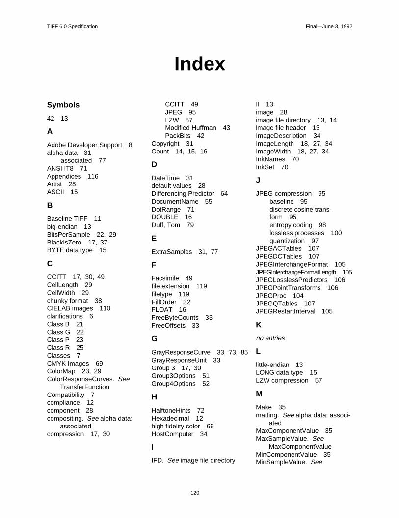
TIFF 6.0 Specification Final—June 3, 1992
120
Index
Symbols
42 13
A
Adobe Developer Support 8alpha data 31
associated 77ANSI IT8 71Appendices 116Artist 28ASCII 15
B
Baseline TIFF 11big-endian 13BitsPerSample 22, 29BlackIsZero 17, 37BYTE data type 15
C
CCITT 17, 30, 49CellLength 29CellWidth 29chunky format 38CIELAB images 110clarifications 6Class B 21Class G 22Class P 23Class R 25Classes 7CMYK Images 69ColorMap 23, 29ColorResponseCurves. See
TransferFunctionCompatibility 7compliance 12component 28compositing. See alpha data:
associatedcompression 17, 30
CCITT 49JPEG 95LZW 57Modified Huffman 43PackBits 42
Copyright 31Count 14, 15, 16
D
DateTime 31default values 28Differencing Predictor 64DocumentName 55DotRange 71DOUBLE 16Duff, Tom 79
E
ExtraSamples 31, 77
F
Facsimile 49file extension 119filetype 119FillOrder 32FLOAT 16FreeByteCounts 33FreeOffsets 33
G
GrayResponseCurve 33, 73, 85GrayResponseUnit 33Group 3 17, 30Group3Options 51Group4Options 52
H
HalftoneHints 72Hexadecimal 12high fidelity color 69HostComputer 34
I
IFD. See image file directory
II 13image 28image file directory 13, 14image file header 13ImageDescription 34ImageLength 18, 27, 34ImageWidth 18, 27, 34InkNames 70InkSet 70
J
JPEG compression 95baseline 95discrete cosine trans-form 95entropy coding 98lossless processes 100quantization 97
JPEGACTables 107JPEGDCTables 107JPEGInterchangeFormat 105JPEGInterchangeFormatLength 105JPEGLosslessPredictors 106JPEGPointTransforms 106JPEGProc 104JPEGQTables 107JPEGRestartInterval 105
K
no entries
L
little-endian 13LONG data type 15LZW compression 57
M
Make 35matting. See alpha data: associ-
atedMaxComponentValue 35MaxSampleValue. See
MaxComponentValueMinComponentValue 35MinSampleValue. See

TIFF 6.0 Specification Final—June 3, 1992
121
MinComponentValueMM 13Model 35Modified Huffman compres-
sion 17, 30, 43multi-page TIFF files 36multiple strips 39
N
NewSubfileType 36NumberOfInks 70
O
Offset 15Orientation 36
P
PackBits compression 42PageName 55PageNumber 55palette color 23, 29, 37PhotometricInterpretation 17, 32, 37pixel 28planar format 38PlanarConfiguration 38Porter, Thomas 79Predictor 64PrimaryChromaticities 83private tags 8proposals
submitting 9
Q
no entries
R
RATIONAL data type 15reduced resolution 36ReferenceBlackWhite 86ResolutionUnit 18, 27, 38revision notes 4RGB images 37row interleave 38RowsPerStrip 19, 27, 39, 68
S
sample. See componentSampleFormat 80SamplesPerPixel 39SBYTE 16
separated images 66SHORT data type 15SLONG 16Software 39SRATIONAL 16SSHORT 16StripByteCounts 19, 27, 40StripOffsets 19, 27, 40StripsPerImage 39subfile 16SubfileType 40. See also
NewSubfileType
T
T4Options 51T6Options 52tag 14TargetPrinter 71Threshholding 41TIFF
administration 8Baseline 11Class P 23Class R 24Classes 17consulting 8extensions 48history 4other extensions 9sample Files 20scope 4structure 13tags - sorted 117
TIFF Advisory Committee 9TileByteCounts 68TileLength 67TileOffsets 68Tiles 66TilesPerImage 67, 68TileWidth 67TransferFunction 84TransferRange 86transparency mask 36, 37type of a field 14
U
UNDEFINED 16
V
no entries
W
WhiteIsZero 17, 37WhitePoint 83
X
XPosition 55XResolution 19, 27, 41
Y
YCbCr images 87, 89YCbCrCoefficients 90YCbCrPositioning 92YCbCrSubSampling 91YPosition 56YResolution 19, 41
Z
no entries