Embed Size (px)
Citation preview

SIMATIC 545/555/575
ProgrammingReference
User Manual
Order Number: PPX:505–8204-2Manual Assembly Number: 2806090–0002Second Edition

This manual contains the following notices intended to ensure personalsafety, as well as to protect the products and connected equipment againstdamage.
! DANGERDANGER indicates an imminently hazardous situation that, if not avoided, willresult in death or serious injury .
DANGER is limited to the most extreme situations.
! WARNINGWARNING indicates a potentially hazardous situation that, if not avoided, couldresult in death or serious injury, and/or property damage.
! CAUTIONCAUTION indicates a potentially hazardous situation that, if not avoided, couldresult in minor or moderate injury, and/or damage to property .
CAUTION is also used for property-damage-only accidents.
Copyright 1998 by Siemens Energy & Automation, Inc.All Rights Reserved — Printed in USA
Reproduction, transmission, or use of this document or contents is not permitted without express consent ofSiemens Energy & Automation, Inc. All rights, including rights created by patent grant or registration of a utility model or design, arereserved.
Since Siemens Energy & Automation, Inc., does not possess full access to data concerning all of the uses and applications ofcustomer’s products, we do not assume responsibility either for customer product design or for any infringements of patents or rightsof others which may result from our assistance.
Safety-RelatedGuidelines

MANUAL PUBLICATION HISTORY
SIMATIC 545/555/575 Programming Reference User ManualOrder Manual Number: PPX:505–8204–2
Refer to this history in all correspondence and/or discussion about this manual.
Event Date Description
Original Issue 3/96 Original Issue (2806090–0001)Second Edition 8/98 Second Edition (2806090–0002)

LIST OF EFFECTIVE PAGES
Pages Description Pages Description
Cover/Copyright SecondHistory/Effective Pages Secondiii — xxxvi Second
1-1 — 1-11 Second2-1 — 2-8 Second3-1 — 3-14 Second4-1 — 4-11 Second5-1 — 5-40 Second6-1 — 6-187 Second7-1 — 7-80 Second
8-1 — 8-15 Second9-1 — 9-45 SecondA-1 — A-8 SecondB-1 — B-6 SecondC-1 — C-15 SecondD-1 — D-4 SecondE-1 — E-37 SecondF-1 — F-1 Second
G-1 — G-32 SecondH-1 — H-17 SecondI-1 — I-12 SecondIndex-1 — Index-10 SecondRegistration Second

Contents iii
Contents
PrefaceIntroduction xxv. . . . . . . . . . . . . . . . . . . . . . . . . . . . . . . . . . . . . . . . . . . . . . . . . . . . . . . . . . . . . . . . . . . . New Features xxvi. . . . . . . . . . . . . . . . . . . . . . . . . . . . . . . . . . . . . . . . . . . . . . . . . . . . . . . . . . . . . . . . . . . How to Use This Manual xxvi. . . . . . . . . . . . . . . . . . . . . . . . . . . . . . . . . . . . . . . . . . . . . . . . . . . . . . . . . TISOFT Programming Software xxvi. . . . . . . . . . . . . . . . . . . . . . . . . . . . . . . . . . . . . . . . . . . . . . . . . . . SIMATIC 505 SoftShop for Windows xxvi. . . . . . . . . . . . . . . . . . . . . . . . . . . . . . . . . . . . . . . . . . . . . . . Technical Assistance xxviii. . . . . . . . . . . . . . . . . . . . . . . . . . . . . . . . . . . . . . . . . . . . . . . . . . . . . . . . . . . .
Chapter 1 Series 505 System Overview1.1 The 545, 555, and 575 Systems 1-2. . . . . . . . . . . . . . . . . . . . . . . . . . . . . . . . . . . . . . . . . . . . . . . . . . .
System Components 1-2. . . . . . . . . . . . . . . . . . . . . . . . . . . . . . . . . . . . . . . . . . . . . . . . . . . . . . . . . . . . Using PROFIBUS-DP I/O 1-2. . . . . . . . . . . . . . . . . . . . . . . . . . . . . . . . . . . . . . . . . . . . . . . . . . . . . . . . . . Local I/O 1-2. . . . . . . . . . . . . . . . . . . . . . . . . . . . . . . . . . . . . . . . . . . . . . . . . . . . . . . . . . . . . . . . . . . . . . . Expansion I/O Channels 1-2. . . . . . . . . . . . . . . . . . . . . . . . . . . . . . . . . . . . . . . . . . . . . . . . . . . . . . . . . Series 505 Remote I/O 1-2. . . . . . . . . . . . . . . . . . . . . . . . . . . . . . . . . . . . . . . . . . . . . . . . . . . . . . . . . . . PROFIBUS-DP I/O 1-4. . . . . . . . . . . . . . . . . . . . . . . . . . . . . . . . . . . . . . . . . . . . . . . . . . . . . . . . . . . . . . . . Output Response on PROFIBUS-DP Slave Devices 1-4. . . . . . . . . . . . . . . . . . . . . . . . . . . . . . . . . Assigning I/O Point Numbers 1-5. . . . . . . . . . . . . . . . . . . . . . . . . . . . . . . . . . . . . . . . . . . . . . . . . . . . .
1.2 Program Execution Operations 1-6. . . . . . . . . . . . . . . . . . . . . . . . . . . . . . . . . . . . . . . . . . . . . . . . . . CPU Scan Operations 1-6. . . . . . . . . . . . . . . . . . . . . . . . . . . . . . . . . . . . . . . . . . . . . . . . . . . . . . . . . . . Interrupt RLL Execution 1-6. . . . . . . . . . . . . . . . . . . . . . . . . . . . . . . . . . . . . . . . . . . . . . . . . . . . . . . . . . Cyclic RLL Execution 1-6. . . . . . . . . . . . . . . . . . . . . . . . . . . . . . . . . . . . . . . . . . . . . . . . . . . . . . . . . . . . Discrete Scan 1-6. . . . . . . . . . . . . . . . . . . . . . . . . . . . . . . . . . . . . . . . . . . . . . . . . . . . . . . . . . . . . . . . . . . Analog Task Processing 1-8. . . . . . . . . . . . . . . . . . . . . . . . . . . . . . . . . . . . . . . . . . . . . . . . . . . . . . . . . Cyclic Analog Tasks 1-8. . . . . . . . . . . . . . . . . . . . . . . . . . . . . . . . . . . . . . . . . . . . . . . . . . . . . . . . . . . . . Non-cyclic Analog Tasks 1-9. . . . . . . . . . . . . . . . . . . . . . . . . . . . . . . . . . . . . . . . . . . . . . . . . . . . . . . . Setting the Scan 1-10. . . . . . . . . . . . . . . . . . . . . . . . . . . . . . . . . . . . . . . . . . . . . . . . . . . . . . . . . . . . . . . .
Chapter 2 Data Representation2.1 Definitions 2-2. . . . . . . . . . . . . . . . . . . . . . . . . . . . . . . . . . . . . . . . . . . . . . . . . . . . . . . . . . . . . . . . . . . . . .
Byte 2-2. . . . . . . . . . . . . . . . . . . . . . . . . . . . . . . . . . . . . . . . . . . . . . . . . . . . . . . . . . . . . . . . . . . . . . . . . . . . Word 2-2. . . . . . . . . . . . . . . . . . . . . . . . . . . . . . . . . . . . . . . . . . . . . . . . . . . . . . . . . . . . . . . . . . . . . . . . . . . Long Word 2-2. . . . . . . . . . . . . . . . . . . . . . . . . . . . . . . . . . . . . . . . . . . . . . . . . . . . . . . . . . . . . . . . . . . . . Image Register 2-2. . . . . . . . . . . . . . . . . . . . . . . . . . . . . . . . . . . . . . . . . . . . . . . . . . . . . . . . . . . . . . . . . I/O Point 2-2. . . . . . . . . . . . . . . . . . . . . . . . . . . . . . . . . . . . . . . . . . . . . . . . . . . . . . . . . . . . . . . . . . . . . . .
2.2 Integers 2-3. . . . . . . . . . . . . . . . . . . . . . . . . . . . . . . . . . . . . . . . . . . . . . . . . . . . . . . . . . . . . . . . . . . . . . . . Signed 16-Bit Integers 2-3. . . . . . . . . . . . . . . . . . . . . . . . . . . . . . . . . . . . . . . . . . . . . . . . . . . . . . . . . . . Unsigned 16-Bit Integers 2-4. . . . . . . . . . . . . . . . . . . . . . . . . . . . . . . . . . . . . . . . . . . . . . . . . . . . . . . . . Signed 32-Bit Integers 2-4. . . . . . . . . . . . . . . . . . . . . . . . . . . . . . . . . . . . . . . . . . . . . . . . . . . . . . . . . . .
2.3 Real Numbers 2-5. . . . . . . . . . . . . . . . . . . . . . . . . . . . . . . . . . . . . . . . . . . . . . . . . . . . . . . . . . . . . . . . . .
2.4 Binary-Coded Decimal 2-6. . . . . . . . . . . . . . . . . . . . . . . . . . . . . . . . . . . . . . . . . . . . . . . . . . . . . . . . . .
2.5 Format for an Address Stored in a Memory Location 2-7. . . . . . . . . . . . . . . . . . . . . . . . . . . . . .

iv Contents
Chapter 3 I/O Concepts
3.1 Reading and Updating the I/O 3-2. . . . . . . . . . . . . . . . . . . . . . . . . . . . . . . . . . . . . . . . . . . . . . . . . . .
Discrete Image Register 3-3. . . . . . . . . . . . . . . . . . . . . . . . . . . . . . . . . . . . . . . . . . . . . . . . . . . . . . . . . Word Image Register 3-5. . . . . . . . . . . . . . . . . . . . . . . . . . . . . . . . . . . . . . . . . . . . . . . . . . . . . . . . . . . .
3.2 Normal I/O Updates 3-6. . . . . . . . . . . . . . . . . . . . . . . . . . . . . . . . . . . . . . . . . . . . . . . . . . . . . . . . . . . .
Discrete Control 3-6. . . . . . . . . . . . . . . . . . . . . . . . . . . . . . . . . . . . . . . . . . . . . . . . . . . . . . . . . . . . . . . . Analog Control 3-6. . . . . . . . . . . . . . . . . . . . . . . . . . . . . . . . . . . . . . . . . . . . . . . . . . . . . . . . . . . . . . . . .
3.3 High Speed I/O Updates 3-8. . . . . . . . . . . . . . . . . . . . . . . . . . . . . . . . . . . . . . . . . . . . . . . . . . . . . . . .
Immediate I/O 3-8. . . . . . . . . . . . . . . . . . . . . . . . . . . . . . . . . . . . . . . . . . . . . . . . . . . . . . . . . . . . . . . . . . Modules that Support Immediate I/O 3-10. . . . . . . . . . . . . . . . . . . . . . . . . . . . . . . . . . . . . . . . . . . . Configuring Immediate I/O 3-10. . . . . . . . . . . . . . . . . . . . . . . . . . . . . . . . . . . . . . . . . . . . . . . . . . . . . .
3.4 Interrupt I/O Operation 3-11. . . . . . . . . . . . . . . . . . . . . . . . . . . . . . . . . . . . . . . . . . . . . . . . . . . . . . . . . .
Overview 3-11. . . . . . . . . . . . . . . . . . . . . . . . . . . . . . . . . . . . . . . . . . . . . . . . . . . . . . . . . . . . . . . . . . . . . . . Configuring the Interrupt Input Module 3-11. . . . . . . . . . . . . . . . . . . . . . . . . . . . . . . . . . . . . . . . . . .
3.5 Control Relays 3-13. . . . . . . . . . . . . . . . . . . . . . . . . . . . . . . . . . . . . . . . . . . . . . . . . . . . . . . . . . . . . . . . . .
Using Retentive and Non-retentive Control Relays 3-14. . . . . . . . . . . . . . . . . . . . . . . . . . . . . . . .
Chapter 4 Controller Memory
4.1 Introduction to Controller Memory 4-2. . . . . . . . . . . . . . . . . . . . . . . . . . . . . . . . . . . . . . . . . . . . . . .
Overview of Controller Memory Types 4-2. . . . . . . . . . . . . . . . . . . . . . . . . . . . . . . . . . . . . . . . . . . . RLL Access to the Memory Types 4-3. . . . . . . . . . . . . . . . . . . . . . . . . . . . . . . . . . . . . . . . . . . . . . . .
4.2 Controller Memory Types 4-4. . . . . . . . . . . . . . . . . . . . . . . . . . . . . . . . . . . . . . . . . . . . . . . . . . . . . . . .
Ladder Memory 4-4. . . . . . . . . . . . . . . . . . . . . . . . . . . . . . . . . . . . . . . . . . . . . . . . . . . . . . . . . . . . . . . . Image Register Memory 4-4. . . . . . . . . . . . . . . . . . . . . . . . . . . . . . . . . . . . . . . . . . . . . . . . . . . . . . . . . Control Relay Memory 4-4. . . . . . . . . . . . . . . . . . . . . . . . . . . . . . . . . . . . . . . . . . . . . . . . . . . . . . . . . . Special Memory 4-4. . . . . . . . . . . . . . . . . . . . . . . . . . . . . . . . . . . . . . . . . . . . . . . . . . . . . . . . . . . . . . . . Compiled Special (CS) Memory 4-4. . . . . . . . . . . . . . . . . . . . . . . . . . . . . . . . . . . . . . . . . . . . . . . . . Temporary Memory 4-4. . . . . . . . . . . . . . . . . . . . . . . . . . . . . . . . . . . . . . . . . . . . . . . . . . . . . . . . . . . . . Variable Memory 4-4. . . . . . . . . . . . . . . . . . . . . . . . . . . . . . . . . . . . . . . . . . . . . . . . . . . . . . . . . . . . . . . Constant Memory 4-5. . . . . . . . . . . . . . . . . . . . . . . . . . . . . . . . . . . . . . . . . . . . . . . . . . . . . . . . . . . . . . Status Word Memory 4-5. . . . . . . . . . . . . . . . . . . . . . . . . . . . . . . . . . . . . . . . . . . . . . . . . . . . . . . . . . . . Timer/Counter Memory 4-5. . . . . . . . . . . . . . . . . . . . . . . . . . . . . . . . . . . . . . . . . . . . . . . . . . . . . . . . . Table Move Memory 4-6. . . . . . . . . . . . . . . . . . . . . . . . . . . . . . . . . . . . . . . . . . . . . . . . . . . . . . . . . . . . One Shot Memory 4-7. . . . . . . . . . . . . . . . . . . . . . . . . . . . . . . . . . . . . . . . . . . . . . . . . . . . . . . . . . . . . . Shift Register Memory 4-8. . . . . . . . . . . . . . . . . . . . . . . . . . . . . . . . . . . . . . . . . . . . . . . . . . . . . . . . . . . Drum Memory 4-9. . . . . . . . . . . . . . . . . . . . . . . . . . . . . . . . . . . . . . . . . . . . . . . . . . . . . . . . . . . . . . . . . . PGTS Discrete Parameter Area 4-10. . . . . . . . . . . . . . . . . . . . . . . . . . . . . . . . . . . . . . . . . . . . . . . . . . . PGTS Word Parameter Area 4-10. . . . . . . . . . . . . . . . . . . . . . . . . . . . . . . . . . . . . . . . . . . . . . . . . . . . . User External Subroutine Memory 4-11. . . . . . . . . . . . . . . . . . . . . . . . . . . . . . . . . . . . . . . . . . . . . . . . Global Memory: 575 Only 4-11. . . . . . . . . . . . . . . . . . . . . . . . . . . . . . . . . . . . . . . . . . . . . . . . . . . . . . . VME Memory: 575 Only 4-11. . . . . . . . . . . . . . . . . . . . . . . . . . . . . . . . . . . . . . . . . . . . . . . . . . . . . . . . .

Contents v
Chapter 5 Programming Concepts
5.1 RLL Components 5-2. . . . . . . . . . . . . . . . . . . . . . . . . . . . . . . . . . . . . . . . . . . . . . . . . . . . . . . . . . . . . . . .
RLL Concept 5-2. . . . . . . . . . . . . . . . . . . . . . . . . . . . . . . . . . . . . . . . . . . . . . . . . . . . . . . . . . . . . . . . . . . RLL Contact 5-3. . . . . . . . . . . . . . . . . . . . . . . . . . . . . . . . . . . . . . . . . . . . . . . . . . . . . . . . . . . . . . . . . . . . RLL Coil 5-8. . . . . . . . . . . . . . . . . . . . . . . . . . . . . . . . . . . . . . . . . . . . . . . . . . . . . . . . . . . . . . . . . . . . . . . . RLL Box Instruction 5-12. . . . . . . . . . . . . . . . . . . . . . . . . . . . . . . . . . . . . . . . . . . . . . . . . . . . . . . . . . . . . . RLL Rung Structure 5-12. . . . . . . . . . . . . . . . . . . . . . . . . . . . . . . . . . . . . . . . . . . . . . . . . . . . . . . . . . . . . . RLL Scan Principles 5-13. . . . . . . . . . . . . . . . . . . . . . . . . . . . . . . . . . . . . . . . . . . . . . . . . . . . . . . . . . . . . .
5.2 Program Compile Sequence 5-14. . . . . . . . . . . . . . . . . . . . . . . . . . . . . . . . . . . . . . . . . . . . . . . . . . . .
5.3 Using Subroutines 5-16. . . . . . . . . . . . . . . . . . . . . . . . . . . . . . . . . . . . . . . . . . . . . . . . . . . . . . . . . . . . . . .
RLL Subroutine Programs 5-16. . . . . . . . . . . . . . . . . . . . . . . . . . . . . . . . . . . . . . . . . . . . . . . . . . . . . . . . SF Programs 5-16. . . . . . . . . . . . . . . . . . . . . . . . . . . . . . . . . . . . . . . . . . . . . . . . . . . . . . . . . . . . . . . . . . . . External Subroutines 5-17. . . . . . . . . . . . . . . . . . . . . . . . . . . . . . . . . . . . . . . . . . . . . . . . . . . . . . . . . . . . .
5.4 Cyclic RLL 5-18. . . . . . . . . . . . . . . . . . . . . . . . . . . . . . . . . . . . . . . . . . . . . . . . . . . . . . . . . . . . . . . . . . . . . .
Overview 5-18. . . . . . . . . . . . . . . . . . . . . . . . . . . . . . . . . . . . . . . . . . . . . . . . . . . . . . . . . . . . . . . . . . . . . . . Cyclic RLL Execution 5-20. . . . . . . . . . . . . . . . . . . . . . . . . . . . . . . . . . . . . . . . . . . . . . . . . . . . . . . . . . . .
5.5 Interrupt RLL (545/555 only) 5-22. . . . . . . . . . . . . . . . . . . . . . . . . . . . . . . . . . . . . . . . . . . . . . . . . . . . . .
The Interrupt RLL Task 5-22. . . . . . . . . . . . . . . . . . . . . . . . . . . . . . . . . . . . . . . . . . . . . . . . . . . . . . . . . . . . Operation 5-25. . . . . . . . . . . . . . . . . . . . . . . . . . . . . . . . . . . . . . . . . . . . . . . . . . . . . . . . . . . . . . . . . . . . . . Performance Characteristics 5-26. . . . . . . . . . . . . . . . . . . . . . . . . . . . . . . . . . . . . . . . . . . . . . . . . . . . Troubleshooting 5-27. . . . . . . . . . . . . . . . . . . . . . . . . . . . . . . . . . . . . . . . . . . . . . . . . . . . . . . . . . . . . . . . .
5.6 Using Real-Time Clock Data 5-28. . . . . . . . . . . . . . . . . . . . . . . . . . . . . . . . . . . . . . . . . . . . . . . . . . . . .
BCD Time of Day 5-28. . . . . . . . . . . . . . . . . . . . . . . . . . . . . . . . . . . . . . . . . . . . . . . . . . . . . . . . . . . . . . . . Binary Time of Day 5-30. . . . . . . . . . . . . . . . . . . . . . . . . . . . . . . . . . . . . . . . . . . . . . . . . . . . . . . . . . . . . . Time of Day Status 5-31. . . . . . . . . . . . . . . . . . . . . . . . . . . . . . . . . . . . . . . . . . . . . . . . . . . . . . . . . . . . . .
5.7 Entering Relay Ladder Logic 5-32. . . . . . . . . . . . . . . . . . . . . . . . . . . . . . . . . . . . . . . . . . . . . . . . . . . . .
SoftShop 505 for Windows 5-32. . . . . . . . . . . . . . . . . . . . . . . . . . . . . . . . . . . . . . . . . . . . . . . . . . . . . . . TISOFT 5-32. . . . . . . . . . . . . . . . . . . . . . . . . . . . . . . . . . . . . . . . . . . . . . . . . . . . . . . . . . . . . . . . . . . . . . . . . . Using APT 5-32. . . . . . . . . . . . . . . . . . . . . . . . . . . . . . . . . . . . . . . . . . . . . . . . . . . . . . . . . . . . . . . . . . . . . . . COM PROFIBUS 5-32. . . . . . . . . . . . . . . . . . . . . . . . . . . . . . . . . . . . . . . . . . . . . . . . . . . . . . . . . . . . . . . . .
5.8 Doing Run-Time Program Edits 5-33. . . . . . . . . . . . . . . . . . . . . . . . . . . . . . . . . . . . . . . . . . . . . . . . . . .
Editing in Run Mode 5-33. . . . . . . . . . . . . . . . . . . . . . . . . . . . . . . . . . . . . . . . . . . . . . . . . . . . . . . . . . . . . Avoid These Actions During Run-Time Edits 5-34. . . . . . . . . . . . . . . . . . . . . . . . . . . . . . . . . . . . . . . . Additional Considerations When Doing Run-Time Edits 5-37. . . . . . . . . . . . . . . . . . . . . . . . . . . .
5.9 Password Protection 5-39. . . . . . . . . . . . . . . . . . . . . . . . . . . . . . . . . . . . . . . . . . . . . . . . . . . . . . . . . . . .
Protected Program Elements 5-39. . . . . . . . . . . . . . . . . . . . . . . . . . . . . . . . . . . . . . . . . . . . . . . . . . . . Disabled and Enabled Passwords 5-39. . . . . . . . . . . . . . . . . . . . . . . . . . . . . . . . . . . . . . . . . . . . . . . . Password Protection Levels 5-40. . . . . . . . . . . . . . . . . . . . . . . . . . . . . . . . . . . . . . . . . . . . . . . . . . . . . . Determining the Current State of Password 5-40. . . . . . . . . . . . . . . . . . . . . . . . . . . . . . . . . . . . . . . Password Effect on EEPROM 5-40. . . . . . . . . . . . . . . . . . . . . . . . . . . . . . . . . . . . . . . . . . . . . . . . . . . . .

vi Contents
Chapter 6 RLL Instruction Set
6.1 Safety Considerations 6-4. . . . . . . . . . . . . . . . . . . . . . . . . . . . . . . . . . . . . . . . . . . . . . . . . . . . . . . . . . . Overview 6-4. . . . . . . . . . . . . . . . . . . . . . . . . . . . . . . . . . . . . . . . . . . . . . . . . . . . . . . . . . . . . . . . . . . . . . . Failure of the Control System 6-4. . . . . . . . . . . . . . . . . . . . . . . . . . . . . . . . . . . . . . . . . . . . . . . . . . . . Inconsistent Program Operation 6-5. . . . . . . . . . . . . . . . . . . . . . . . . . . . . . . . . . . . . . . . . . . . . . . . . Editing an Active Process 6-5. . . . . . . . . . . . . . . . . . . . . . . . . . . . . . . . . . . . . . . . . . . . . . . . . . . . . . . .
6.2 Introduction 6-6. . . . . . . . . . . . . . . . . . . . . . . . . . . . . . . . . . . . . . . . . . . . . . . . . . . . . . . . . . . . . . . . . . . .
6.3 Absolute Value 6-11. . . . . . . . . . . . . . . . . . . . . . . . . . . . . . . . . . . . . . . . . . . . . . . . . . . . . . . . . . . . . . . . . ABSV Description 6-11. . . . . . . . . . . . . . . . . . . . . . . . . . . . . . . . . . . . . . . . . . . . . . . . . . . . . . . . . . . . . . . ABSV Operation 6-11. . . . . . . . . . . . . . . . . . . . . . . . . . . . . . . . . . . . . . . . . . . . . . . . . . . . . . . . . . . . . . . .
6.4 Add 6-12. . . . . . . . . . . . . . . . . . . . . . . . . . . . . . . . . . . . . . . . . . . . . . . . . . . . . . . . . . . . . . . . . . . . . . . . . . . . ADD Description 6-12. . . . . . . . . . . . . . . . . . . . . . . . . . . . . . . . . . . . . . . . . . . . . . . . . . . . . . . . . . . . . . . . ADD Operation 6-12. . . . . . . . . . . . . . . . . . . . . . . . . . . . . . . . . . . . . . . . . . . . . . . . . . . . . . . . . . . . . . . . .
6.5 Bit Clear 6-13. . . . . . . . . . . . . . . . . . . . . . . . . . . . . . . . . . . . . . . . . . . . . . . . . . . . . . . . . . . . . . . . . . . . . . . . BITC Description 6-13. . . . . . . . . . . . . . . . . . . . . . . . . . . . . . . . . . . . . . . . . . . . . . . . . . . . . . . . . . . . . . . . BITC Operation 6-13. . . . . . . . . . . . . . . . . . . . . . . . . . . . . . . . . . . . . . . . . . . . . . . . . . . . . . . . . . . . . . . . .
6.6 Bit Pick 6-14. . . . . . . . . . . . . . . . . . . . . . . . . . . . . . . . . . . . . . . . . . . . . . . . . . . . . . . . . . . . . . . . . . . . . . . . . BITP Description 6-14. . . . . . . . . . . . . . . . . . . . . . . . . . . . . . . . . . . . . . . . . . . . . . . . . . . . . . . . . . . . . . . . . BITP Operation 6-14. . . . . . . . . . . . . . . . . . . . . . . . . . . . . . . . . . . . . . . . . . . . . . . . . . . . . . . . . . . . . . . . . .
6.7 Bit Set 6-15. . . . . . . . . . . . . . . . . . . . . . . . . . . . . . . . . . . . . . . . . . . . . . . . . . . . . . . . . . . . . . . . . . . . . . . . . . BITS Description 6-15. . . . . . . . . . . . . . . . . . . . . . . . . . . . . . . . . . . . . . . . . . . . . . . . . . . . . . . . . . . . . . . . . BITS Operation 6-15. . . . . . . . . . . . . . . . . . . . . . . . . . . . . . . . . . . . . . . . . . . . . . . . . . . . . . . . . . . . . . . . . .
6.8 Convert Binary to BCD 6-16. . . . . . . . . . . . . . . . . . . . . . . . . . . . . . . . . . . . . . . . . . . . . . . . . . . . . . . . . . CBD Description 6-16. . . . . . . . . . . . . . . . . . . . . . . . . . . . . . . . . . . . . . . . . . . . . . . . . . . . . . . . . . . . . . . . CBD Operation 6-16. . . . . . . . . . . . . . . . . . . . . . . . . . . . . . . . . . . . . . . . . . . . . . . . . . . . . . . . . . . . . . . . .
6.9 Convert BCD to Binary 6-18. . . . . . . . . . . . . . . . . . . . . . . . . . . . . . . . . . . . . . . . . . . . . . . . . . . . . . . . . . CDB Description 6-18. . . . . . . . . . . . . . . . . . . . . . . . . . . . . . . . . . . . . . . . . . . . . . . . . . . . . . . . . . . . . . . . CDB Operation 6-18. . . . . . . . . . . . . . . . . . . . . . . . . . . . . . . . . . . . . . . . . . . . . . . . . . . . . . . . . . . . . . . . .
6.10 Compare 6-20. . . . . . . . . . . . . . . . . . . . . . . . . . . . . . . . . . . . . . . . . . . . . . . . . . . . . . . . . . . . . . . . . . . . . . . CMP Description 6-20. . . . . . . . . . . . . . . . . . . . . . . . . . . . . . . . . . . . . . . . . . . . . . . . . . . . . . . . . . . . . . . . CMP Operation 6-20. . . . . . . . . . . . . . . . . . . . . . . . . . . . . . . . . . . . . . . . . . . . . . . . . . . . . . . . . . . . . . . . .
6.11 Coils 6-22. . . . . . . . . . . . . . . . . . . . . . . . . . . . . . . . . . . . . . . . . . . . . . . . . . . . . . . . . . . . . . . . . . . . . . . . . . .
6.12 Contacts 6-23. . . . . . . . . . . . . . . . . . . . . . . . . . . . . . . . . . . . . . . . . . . . . . . . . . . . . . . . . . . . . . . . . . . . . . .
6.13 Counter (Up Counter) 6-24. . . . . . . . . . . . . . . . . . . . . . . . . . . . . . . . . . . . . . . . . . . . . . . . . . . . . . . . . . . CTR Description 6-24. . . . . . . . . . . . . . . . . . . . . . . . . . . . . . . . . . . . . . . . . . . . . . . . . . . . . . . . . . . . . . . . . CTR Operation 6-24. . . . . . . . . . . . . . . . . . . . . . . . . . . . . . . . . . . . . . . . . . . . . . . . . . . . . . . . . . . . . . . . . . Using the Counter Variables 6-25. . . . . . . . . . . . . . . . . . . . . . . . . . . . . . . . . . . . . . . . . . . . . . . . . . . . .

Contents vii
6.14 Discrete Control Alarm Timer 6-26. . . . . . . . . . . . . . . . . . . . . . . . . . . . . . . . . . . . . . . . . . . . . . . . . . . . DCAT Description 6-26. . . . . . . . . . . . . . . . . . . . . . . . . . . . . . . . . . . . . . . . . . . . . . . . . . . . . . . . . . . . . . . DCAT State Changes 6-27. . . . . . . . . . . . . . . . . . . . . . . . . . . . . . . . . . . . . . . . . . . . . . . . . . . . . . . . . . . . DCAT Operation 6-28. . . . . . . . . . . . . . . . . . . . . . . . . . . . . . . . . . . . . . . . . . . . . . . . . . . . . . . . . . . . . . . . Open (Input On) 6-28. . . . . . . . . . . . . . . . . . . . . . . . . . . . . . . . . . . . . . . . . . . . . . . . . . . . . . . . . . . . . . . . Close (Input Off) 6-28. . . . . . . . . . . . . . . . . . . . . . . . . . . . . . . . . . . . . . . . . . . . . . . . . . . . . . . . . . . . . . . . Using the DCAT Variables 6-29. . . . . . . . . . . . . . . . . . . . . . . . . . . . . . . . . . . . . . . . . . . . . . . . . . . . . . . .
6.15 Date Compare 6-30. . . . . . . . . . . . . . . . . . . . . . . . . . . . . . . . . . . . . . . . . . . . . . . . . . . . . . . . . . . . . . . . . DCMP Description 6-30. . . . . . . . . . . . . . . . . . . . . . . . . . . . . . . . . . . . . . . . . . . . . . . . . . . . . . . . . . . . . . DCMP Operation 6-31. . . . . . . . . . . . . . . . . . . . . . . . . . . . . . . . . . . . . . . . . . . . . . . . . . . . . . . . . . . . . . .
6.16 Divide 6-32. . . . . . . . . . . . . . . . . . . . . . . . . . . . . . . . . . . . . . . . . . . . . . . . . . . . . . . . . . . . . . . . . . . . . . . . . . DIV Description 6-32. . . . . . . . . . . . . . . . . . . . . . . . . . . . . . . . . . . . . . . . . . . . . . . . . . . . . . . . . . . . . . . . . DIV Operation 6-33. . . . . . . . . . . . . . . . . . . . . . . . . . . . . . . . . . . . . . . . . . . . . . . . . . . . . . . . . . . . . . . . . .
6.17 Time Driven Drum 6-34. . . . . . . . . . . . . . . . . . . . . . . . . . . . . . . . . . . . . . . . . . . . . . . . . . . . . . . . . . . . . . . DRUM Description 6-34. . . . . . . . . . . . . . . . . . . . . . . . . . . . . . . . . . . . . . . . . . . . . . . . . . . . . . . . . . . . . . . DRUM Operation 6-34. . . . . . . . . . . . . . . . . . . . . . . . . . . . . . . . . . . . . . . . . . . . . . . . . . . . . . . . . . . . . . . Calculating Counts/Step 6-36. . . . . . . . . . . . . . . . . . . . . . . . . . . . . . . . . . . . . . . . . . . . . . . . . . . . . . . . Using DRUM Variables 6-36. . . . . . . . . . . . . . . . . . . . . . . . . . . . . . . . . . . . . . . . . . . . . . . . . . . . . . . . . . .
6.18 Date Set 6-38. . . . . . . . . . . . . . . . . . . . . . . . . . . . . . . . . . . . . . . . . . . . . . . . . . . . . . . . . . . . . . . . . . . . . . . . DSET Description 6-38. . . . . . . . . . . . . . . . . . . . . . . . . . . . . . . . . . . . . . . . . . . . . . . . . . . . . . . . . . . . . . . . DSET Operation 6-39. . . . . . . . . . . . . . . . . . . . . . . . . . . . . . . . . . . . . . . . . . . . . . . . . . . . . . . . . . . . . . . . .
6.19 Time/Event Driven Drum 6-40. . . . . . . . . . . . . . . . . . . . . . . . . . . . . . . . . . . . . . . . . . . . . . . . . . . . . . . . . EDRUM Description 6-40. . . . . . . . . . . . . . . . . . . . . . . . . . . . . . . . . . . . . . . . . . . . . . . . . . . . . . . . . . . . . EDRUM Operation 6-41. . . . . . . . . . . . . . . . . . . . . . . . . . . . . . . . . . . . . . . . . . . . . . . . . . . . . . . . . . . . . . Calculating Counts/Step 6-42. . . . . . . . . . . . . . . . . . . . . . . . . . . . . . . . . . . . . . . . . . . . . . . . . . . . . . . . Timer-triggered Advance Only 6-42. . . . . . . . . . . . . . . . . . . . . . . . . . . . . . . . . . . . . . . . . . . . . . . . . . Event-triggered Advance Only 6-42. . . . . . . . . . . . . . . . . . . . . . . . . . . . . . . . . . . . . . . . . . . . . . . . . . Timer and Event- Triggered Advance 6-43. . . . . . . . . . . . . . . . . . . . . . . . . . . . . . . . . . . . . . . . . . . . Timer or External Event-triggered Advance 6-43. . . . . . . . . . . . . . . . . . . . . . . . . . . . . . . . . . . . . . . Using EDRUM Variables 6-43. . . . . . . . . . . . . . . . . . . . . . . . . . . . . . . . . . . . . . . . . . . . . . . . . . . . . . . . . .
6.20 Unconditional End 6-44. . . . . . . . . . . . . . . . . . . . . . . . . . . . . . . . . . . . . . . . . . . . . . . . . . . . . . . . . . . . . . END Description 6-44. . . . . . . . . . . . . . . . . . . . . . . . . . . . . . . . . . . . . . . . . . . . . . . . . . . . . . . . . . . . . . . . END Operation 6-44. . . . . . . . . . . . . . . . . . . . . . . . . . . . . . . . . . . . . . . . . . . . . . . . . . . . . . . . . . . . . . . . .
6.21 Conditional End 6-45. . . . . . . . . . . . . . . . . . . . . . . . . . . . . . . . . . . . . . . . . . . . . . . . . . . . . . . . . . . . . . . . ENDC Description 6-45. . . . . . . . . . . . . . . . . . . . . . . . . . . . . . . . . . . . . . . . . . . . . . . . . . . . . . . . . . . . . . . ENDC Operation 6-45. . . . . . . . . . . . . . . . . . . . . . . . . . . . . . . . . . . . . . . . . . . . . . . . . . . . . . . . . . . . . . . .
6.22 Go To Subroutine 6-46. . . . . . . . . . . . . . . . . . . . . . . . . . . . . . . . . . . . . . . . . . . . . . . . . . . . . . . . . . . . . . . GTS Description 6-46. . . . . . . . . . . . . . . . . . . . . . . . . . . . . . . . . . . . . . . . . . . . . . . . . . . . . . . . . . . . . . . . . GTS Operation 6-46. . . . . . . . . . . . . . . . . . . . . . . . . . . . . . . . . . . . . . . . . . . . . . . . . . . . . . . . . . . . . . . . . .
6.23 Indexed Matrix Compare 6-48. . . . . . . . . . . . . . . . . . . . . . . . . . . . . . . . . . . . . . . . . . . . . . . . . . . . . . . IMC Description 6-48. . . . . . . . . . . . . . . . . . . . . . . . . . . . . . . . . . . . . . . . . . . . . . . . . . . . . . . . . . . . . . . . IMC Operation 6-49. . . . . . . . . . . . . . . . . . . . . . . . . . . . . . . . . . . . . . . . . . . . . . . . . . . . . . . . . . . . . . . . .

viii Contents
6.24 Immediate I/O Read/Write 6-50. . . . . . . . . . . . . . . . . . . . . . . . . . . . . . . . . . . . . . . . . . . . . . . . . . . . . . IORW Description 6-50. . . . . . . . . . . . . . . . . . . . . . . . . . . . . . . . . . . . . . . . . . . . . . . . . . . . . . . . . . . . . . . IORW Operation 6-50. . . . . . . . . . . . . . . . . . . . . . . . . . . . . . . . . . . . . . . . . . . . . . . . . . . . . . . . . . . . . . . .
6.25 Jump 6-52. . . . . . . . . . . . . . . . . . . . . . . . . . . . . . . . . . . . . . . . . . . . . . . . . . . . . . . . . . . . . . . . . . . . . . . . . . JMP Description 6-52. . . . . . . . . . . . . . . . . . . . . . . . . . . . . . . . . . . . . . . . . . . . . . . . . . . . . . . . . . . . . . . . JMP/JMPE Operation 6-52. . . . . . . . . . . . . . . . . . . . . . . . . . . . . . . . . . . . . . . . . . . . . . . . . . . . . . . . . . .
6.26 Load Address 6-54. . . . . . . . . . . . . . . . . . . . . . . . . . . . . . . . . . . . . . . . . . . . . . . . . . . . . . . . . . . . . . . . . . . LDA Description 6-54. . . . . . . . . . . . . . . . . . . . . . . . . . . . . . . . . . . . . . . . . . . . . . . . . . . . . . . . . . . . . . . . . LDA Operation 6-55. . . . . . . . . . . . . . . . . . . . . . . . . . . . . . . . . . . . . . . . . . . . . . . . . . . . . . . . . . . . . . . . . Specifying Source 6-57. . . . . . . . . . . . . . . . . . . . . . . . . . . . . . . . . . . . . . . . . . . . . . . . . . . . . . . . . . . . . . . Specifying Index for Source 6-57. . . . . . . . . . . . . . . . . . . . . . . . . . . . . . . . . . . . . . . . . . . . . . . . . . . . . . Specifying Destination 6-58. . . . . . . . . . . . . . . . . . . . . . . . . . . . . . . . . . . . . . . . . . . . . . . . . . . . . . . . . . Specifying Index for Destination 6-58. . . . . . . . . . . . . . . . . . . . . . . . . . . . . . . . . . . . . . . . . . . . . . . . .
6.27 Load Data Constant 6-59. . . . . . . . . . . . . . . . . . . . . . . . . . . . . . . . . . . . . . . . . . . . . . . . . . . . . . . . . . . . . LDC Description 6-59. . . . . . . . . . . . . . . . . . . . . . . . . . . . . . . . . . . . . . . . . . . . . . . . . . . . . . . . . . . . . . . . LDC Operation 6-59. . . . . . . . . . . . . . . . . . . . . . . . . . . . . . . . . . . . . . . . . . . . . . . . . . . . . . . . . . . . . . . . .
6.28 Lock Memory 6-60. . . . . . . . . . . . . . . . . . . . . . . . . . . . . . . . . . . . . . . . . . . . . . . . . . . . . . . . . . . . . . . . . . . LOCK Description 6-60. . . . . . . . . . . . . . . . . . . . . . . . . . . . . . . . . . . . . . . . . . . . . . . . . . . . . . . . . . . . . . . Acquiring Control of the Lock 6-60. . . . . . . . . . . . . . . . . . . . . . . . . . . . . . . . . . . . . . . . . . . . . . . . . . . How the Lock Protects Memory 6-62. . . . . . . . . . . . . . . . . . . . . . . . . . . . . . . . . . . . . . . . . . . . . . . . . .
6.29 Motor Control Alarm Timer 6-63. . . . . . . . . . . . . . . . . . . . . . . . . . . . . . . . . . . . . . . . . . . . . . . . . . . . . . . MCAT Description 6-63. . . . . . . . . . . . . . . . . . . . . . . . . . . . . . . . . . . . . . . . . . . . . . . . . . . . . . . . . . . . . . . MCAT State Changes 6-64. . . . . . . . . . . . . . . . . . . . . . . . . . . . . . . . . . . . . . . . . . . . . . . . . . . . . . . . . . . MCAT Operation 6-66. . . . . . . . . . . . . . . . . . . . . . . . . . . . . . . . . . . . . . . . . . . . . . . . . . . . . . . . . . . . . . . . Open Input Turns On 6-66. . . . . . . . . . . . . . . . . . . . . . . . . . . . . . . . . . . . . . . . . . . . . . . . . . . . . . . . . . . . Close Input Turns On 6-66. . . . . . . . . . . . . . . . . . . . . . . . . . . . . . . . . . . . . . . . . . . . . . . . . . . . . . . . . . . . Using the MCAT Variables 6-67. . . . . . . . . . . . . . . . . . . . . . . . . . . . . . . . . . . . . . . . . . . . . . . . . . . . . . .
6.30 Master Control Relay 6-68. . . . . . . . . . . . . . . . . . . . . . . . . . . . . . . . . . . . . . . . . . . . . . . . . . . . . . . . . . . . MCR Description 6-68. . . . . . . . . . . . . . . . . . . . . . . . . . . . . . . . . . . . . . . . . . . . . . . . . . . . . . . . . . . . . . . . MCR/MCRE Operation 6-68. . . . . . . . . . . . . . . . . . . . . . . . . . . . . . . . . . . . . . . . . . . . . . . . . . . . . . . . . .
6.31 Maskable Event Drum, Discrete 6-72. . . . . . . . . . . . . . . . . . . . . . . . . . . . . . . . . . . . . . . . . . . . . . . . . . MDRMD Description 6-72. . . . . . . . . . . . . . . . . . . . . . . . . . . . . . . . . . . . . . . . . . . . . . . . . . . . . . . . . . . . . MDRMD Operation 6-73. . . . . . . . . . . . . . . . . . . . . . . . . . . . . . . . . . . . . . . . . . . . . . . . . . . . . . . . . . . . . Defining the Mask 6-74. . . . . . . . . . . . . . . . . . . . . . . . . . . . . . . . . . . . . . . . . . . . . . . . . . . . . . . . . . . . . . . Calculating Counts/Step 6-74. . . . . . . . . . . . . . . . . . . . . . . . . . . . . . . . . . . . . . . . . . . . . . . . . . . . . . . . Timer-triggered Advance Only 6-74. . . . . . . . . . . . . . . . . . . . . . . . . . . . . . . . . . . . . . . . . . . . . . . . . . Event-triggered Advance Only 6-74. . . . . . . . . . . . . . . . . . . . . . . . . . . . . . . . . . . . . . . . . . . . . . . . . . Timer and Event-Triggered Advance 6-75. . . . . . . . . . . . . . . . . . . . . . . . . . . . . . . . . . . . . . . . . . . . . Timer or External Event-Triggered Advance 6-75. . . . . . . . . . . . . . . . . . . . . . . . . . . . . . . . . . . . . . . Using MDRMD Variables 6-75. . . . . . . . . . . . . . . . . . . . . . . . . . . . . . . . . . . . . . . . . . . . . . . . . . . . . . . . .

Contents ix
6.32 Maskable Event Drum, Word 6-76. . . . . . . . . . . . . . . . . . . . . . . . . . . . . . . . . . . . . . . . . . . . . . . . . . . . .
MDRMW Description 6-76. . . . . . . . . . . . . . . . . . . . . . . . . . . . . . . . . . . . . . . . . . . . . . . . . . . . . . . . . . . . MDRMW Operation 6-78. . . . . . . . . . . . . . . . . . . . . . . . . . . . . . . . . . . . . . . . . . . . . . . . . . . . . . . . . . . . . Defining the Mask 6-79. . . . . . . . . . . . . . . . . . . . . . . . . . . . . . . . . . . . . . . . . . . . . . . . . . . . . . . . . . . . . . . Calculating Counts/Step 6-79. . . . . . . . . . . . . . . . . . . . . . . . . . . . . . . . . . . . . . . . . . . . . . . . . . . . . . . . Timer-triggered Advance Only 6-80. . . . . . . . . . . . . . . . . . . . . . . . . . . . . . . . . . . . . . . . . . . . . . . . . . Event-triggered Advance Only 6-80. . . . . . . . . . . . . . . . . . . . . . . . . . . . . . . . . . . . . . . . . . . . . . . . . . Timer and Event-Triggered Advance 6-80. . . . . . . . . . . . . . . . . . . . . . . . . . . . . . . . . . . . . . . . . . . . . Timer or External Event-triggered Advance 6-80. . . . . . . . . . . . . . . . . . . . . . . . . . . . . . . . . . . . . . . Using MDRMD Variables 6-81. . . . . . . . . . . . . . . . . . . . . . . . . . . . . . . . . . . . . . . . . . . . . . . . . . . . . . . . .
6.33 Move Image Register from Table 6-82. . . . . . . . . . . . . . . . . . . . . . . . . . . . . . . . . . . . . . . . . . . . . . . . .
MIRFT Description 6-82. . . . . . . . . . . . . . . . . . . . . . . . . . . . . . . . . . . . . . . . . . . . . . . . . . . . . . . . . . . . . . . MIRFT Operation 6-82. . . . . . . . . . . . . . . . . . . . . . . . . . . . . . . . . . . . . . . . . . . . . . . . . . . . . . . . . . . . . . . .
6.34 Move Image Register to Table 6-84. . . . . . . . . . . . . . . . . . . . . . . . . . . . . . . . . . . . . . . . . . . . . . . . . . .
MIRTT Description 6-84. . . . . . . . . . . . . . . . . . . . . . . . . . . . . . . . . . . . . . . . . . . . . . . . . . . . . . . . . . . . . . . MIRTT Operation 6-84. . . . . . . . . . . . . . . . . . . . . . . . . . . . . . . . . . . . . . . . . . . . . . . . . . . . . . . . . . . . . . . .
6.35 Move Image Register to Word 6-86. . . . . . . . . . . . . . . . . . . . . . . . . . . . . . . . . . . . . . . . . . . . . . . . . . .
MIRW Description 6-86. . . . . . . . . . . . . . . . . . . . . . . . . . . . . . . . . . . . . . . . . . . . . . . . . . . . . . . . . . . . . . . MIRW Operation 6-86. . . . . . . . . . . . . . . . . . . . . . . . . . . . . . . . . . . . . . . . . . . . . . . . . . . . . . . . . . . . . . . .
6.36 Move Element 6-88. . . . . . . . . . . . . . . . . . . . . . . . . . . . . . . . . . . . . . . . . . . . . . . . . . . . . . . . . . . . . . . . . .
MOVE Description 6-88. . . . . . . . . . . . . . . . . . . . . . . . . . . . . . . . . . . . . . . . . . . . . . . . . . . . . . . . . . . . . . MOVE Operation 6-89. . . . . . . . . . . . . . . . . . . . . . . . . . . . . . . . . . . . . . . . . . . . . . . . . . . . . . . . . . . . . . . Specifying Type of Elements 6-93. . . . . . . . . . . . . . . . . . . . . . . . . . . . . . . . . . . . . . . . . . . . . . . . . . . . . Specifying Source 6-93. . . . . . . . . . . . . . . . . . . . . . . . . . . . . . . . . . . . . . . . . . . . . . . . . . . . . . . . . . . . . . . Specifying Index for Source 6-93. . . . . . . . . . . . . . . . . . . . . . . . . . . . . . . . . . . . . . . . . . . . . . . . . . . . . . Specifying Destination 6-94. . . . . . . . . . . . . . . . . . . . . . . . . . . . . . . . . . . . . . . . . . . . . . . . . . . . . . . . . . Specifying Index for Destination 6-94. . . . . . . . . . . . . . . . . . . . . . . . . . . . . . . . . . . . . . . . . . . . . . . . . Specifying Number of Elements to Move 6-95. . . . . . . . . . . . . . . . . . . . . . . . . . . . . . . . . . . . . . . . .
6.37 Move Word 6-96. . . . . . . . . . . . . . . . . . . . . . . . . . . . . . . . . . . . . . . . . . . . . . . . . . . . . . . . . . . . . . . . . . . . .
MOVW Description 6-96. . . . . . . . . . . . . . . . . . . . . . . . . . . . . . . . . . . . . . . . . . . . . . . . . . . . . . . . . . . . . MOVW Operation 6-97. . . . . . . . . . . . . . . . . . . . . . . . . . . . . . . . . . . . . . . . . . . . . . . . . . . . . . . . . . . . . .
6.38 Multiply 6-98. . . . . . . . . . . . . . . . . . . . . . . . . . . . . . . . . . . . . . . . . . . . . . . . . . . . . . . . . . . . . . . . . . . . . . . .
MULT Description 6-98. . . . . . . . . . . . . . . . . . . . . . . . . . . . . . . . . . . . . . . . . . . . . . . . . . . . . . . . . . . . . . . . MULT Operation 6-98. . . . . . . . . . . . . . . . . . . . . . . . . . . . . . . . . . . . . . . . . . . . . . . . . . . . . . . . . . . . . . . .
6.39 Move Word from Table 6-100. . . . . . . . . . . . . . . . . . . . . . . . . . . . . . . . . . . . . . . . . . . . . . . . . . . . . . . . . .
MWFT Description 6-100. . . . . . . . . . . . . . . . . . . . . . . . . . . . . . . . . . . . . . . . . . . . . . . . . . . . . . . . . . . . . . . MWFT Operation 6-100. . . . . . . . . . . . . . . . . . . . . . . . . . . . . . . . . . . . . . . . . . . . . . . . . . . . . . . . . . . . . . . .
6.40 Move Word with Index 6-102. . . . . . . . . . . . . . . . . . . . . . . . . . . . . . . . . . . . . . . . . . . . . . . . . . . . . . . . . .
MWI Description 6-102. . . . . . . . . . . . . . . . . . . . . . . . . . . . . . . . . . . . . . . . . . . . . . . . . . . . . . . . . . . . . . . . MWI Operation 6-102. . . . . . . . . . . . . . . . . . . . . . . . . . . . . . . . . . . . . . . . . . . . . . . . . . . . . . . . . . . . . . . . .

x Contents
6.41 Move Word to Image Register 6-104. . . . . . . . . . . . . . . . . . . . . . . . . . . . . . . . . . . . . . . . . . . . . . . . . . .
MWIR Description 6-104. . . . . . . . . . . . . . . . . . . . . . . . . . . . . . . . . . . . . . . . . . . . . . . . . . . . . . . . . . . . . . . MWIR Operation 6-104. . . . . . . . . . . . . . . . . . . . . . . . . . . . . . . . . . . . . . . . . . . . . . . . . . . . . . . . . . . . . . . .
6.42 Move Word To Table 6-106. . . . . . . . . . . . . . . . . . . . . . . . . . . . . . . . . . . . . . . . . . . . . . . . . . . . . . . . . . . . .
MWTT Description 6-106. . . . . . . . . . . . . . . . . . . . . . . . . . . . . . . . . . . . . . . . . . . . . . . . . . . . . . . . . . . . . . . MWTT Operation 6-106. . . . . . . . . . . . . . . . . . . . . . . . . . . . . . . . . . . . . . . . . . . . . . . . . . . . . . . . . . . . . . . .
6.43 NOT 6-108. . . . . . . . . . . . . . . . . . . . . . . . . . . . . . . . . . . . . . . . . . . . . . . . . . . . . . . . . . . . . . . . . . . . . . . . . . . .
NOT Description 6-108. . . . . . . . . . . . . . . . . . . . . . . . . . . . . . . . . . . . . . . . . . . . . . . . . . . . . . . . . . . . . . . . NOT Operation 6-108. . . . . . . . . . . . . . . . . . . . . . . . . . . . . . . . . . . . . . . . . . . . . . . . . . . . . . . . . . . . . . . . .
6.44 One Shot 6-109. . . . . . . . . . . . . . . . . . . . . . . . . . . . . . . . . . . . . . . . . . . . . . . . . . . . . . . . . . . . . . . . . . . . . . .
One Shot Description 6-109. . . . . . . . . . . . . . . . . . . . . . . . . . . . . . . . . . . . . . . . . . . . . . . . . . . . . . . . . . . One Shot Operation 6-109. . . . . . . . . . . . . . . . . . . . . . . . . . . . . . . . . . . . . . . . . . . . . . . . . . . . . . . . . . . .
6.45 PID Loop 6-110. . . . . . . . . . . . . . . . . . . . . . . . . . . . . . . . . . . . . . . . . . . . . . . . . . . . . . . . . . . . . . . . . . . . . . .
PID Fast Loop Description 6-110. . . . . . . . . . . . . . . . . . . . . . . . . . . . . . . . . . . . . . . . . . . . . . . . . . . . . . . PID Operation 6-110. . . . . . . . . . . . . . . . . . . . . . . . . . . . . . . . . . . . . . . . . . . . . . . . . . . . . . . . . . . . . . . . . .
6.46 Parameterized Go To Subroutine 6-112. . . . . . . . . . . . . . . . . . . . . . . . . . . . . . . . . . . . . . . . . . . . . . . . .
PGTS Description 6-112. . . . . . . . . . . . . . . . . . . . . . . . . . . . . . . . . . . . . . . . . . . . . . . . . . . . . . . . . . . . . . . . PGTS Operation 6-112. . . . . . . . . . . . . . . . . . . . . . . . . . . . . . . . . . . . . . . . . . . . . . . . . . . . . . . . . . . . . . . .
6.47 Parameterized Go To Subroutine (Zero) 6-118. . . . . . . . . . . . . . . . . . . . . . . . . . . . . . . . . . . . . . . . . . .
PGTSZ Description 6-118. . . . . . . . . . . . . . . . . . . . . . . . . . . . . . . . . . . . . . . . . . . . . . . . . . . . . . . . . . . . . . . PGTSZ Operation 6-119. . . . . . . . . . . . . . . . . . . . . . . . . . . . . . . . . . . . . . . . . . . . . . . . . . . . . . . . . . . . . . . .
6.48 Read Slave Diagnostic (RSD) 6-120. . . . . . . . . . . . . . . . . . . . . . . . . . . . . . . . . . . . . . . . . . . . . . . . . . . .
RSD Description 6-120. . . . . . . . . . . . . . . . . . . . . . . . . . . . . . . . . . . . . . . . . . . . . . . . . . . . . . . . . . . . . . . . . RSD Operation 6-121. . . . . . . . . . . . . . . . . . . . . . . . . . . . . . . . . . . . . . . . . . . . . . . . . . . . . . . . . . . . . . . . . .
6.49 Return from Subroutine 6-122. . . . . . . . . . . . . . . . . . . . . . . . . . . . . . . . . . . . . . . . . . . . . . . . . . . . . . . . . .
RTN Description 6-122. . . . . . . . . . . . . . . . . . . . . . . . . . . . . . . . . . . . . . . . . . . . . . . . . . . . . . . . . . . . . . . . . RTN Operation 6-122. . . . . . . . . . . . . . . . . . . . . . . . . . . . . . . . . . . . . . . . . . . . . . . . . . . . . . . . . . . . . . . . . .
6.50 Subroutine 6-123. . . . . . . . . . . . . . . . . . . . . . . . . . . . . . . . . . . . . . . . . . . . . . . . . . . . . . . . . . . . . . . . . . . . . .
SBR Description 6-123. . . . . . . . . . . . . . . . . . . . . . . . . . . . . . . . . . . . . . . . . . . . . . . . . . . . . . . . . . . . . . . . . SBR Operation 6-123. . . . . . . . . . . . . . . . . . . . . . . . . . . . . . . . . . . . . . . . . . . . . . . . . . . . . . . . . . . . . . . . . .
6.51 Call an SF Program 6-126. . . . . . . . . . . . . . . . . . . . . . . . . . . . . . . . . . . . . . . . . . . . . . . . . . . . . . . . . . . . . .
SFPGM Description 6-126. . . . . . . . . . . . . . . . . . . . . . . . . . . . . . . . . . . . . . . . . . . . . . . . . . . . . . . . . . . . . . SFPGM Operation 6-126. . . . . . . . . . . . . . . . . . . . . . . . . . . . . . . . . . . . . . . . . . . . . . . . . . . . . . . . . . . . . . . In-line SFPGM Execution 6-127. . . . . . . . . . . . . . . . . . . . . . . . . . . . . . . . . . . . . . . . . . . . . . . . . . . . . . . . .
6.52 Call SF Subroutines from RLL 6-128. . . . . . . . . . . . . . . . . . . . . . . . . . . . . . . . . . . . . . . . . . . . . . . . . . . . .
SFSUB Description 6-128. . . . . . . . . . . . . . . . . . . . . . . . . . . . . . . . . . . . . . . . . . . . . . . . . . . . . . . . . . . . . . . SFSUB Operation 6-129. . . . . . . . . . . . . . . . . . . . . . . . . . . . . . . . . . . . . . . . . . . . . . . . . . . . . . . . . . . . . . . . In-line SFSUB Execution 6-130. . . . . . . . . . . . . . . . . . . . . . . . . . . . . . . . . . . . . . . . . . . . . . . . . . . . . . . . . .

Contents xi
6.53 Bit Shift Register 6-132. . . . . . . . . . . . . . . . . . . . . . . . . . . . . . . . . . . . . . . . . . . . . . . . . . . . . . . . . . . . . . . . SHRB Description 6-132. . . . . . . . . . . . . . . . . . . . . . . . . . . . . . . . . . . . . . . . . . . . . . . . . . . . . . . . . . . . . . . . SHRB Operation 6-133. . . . . . . . . . . . . . . . . . . . . . . . . . . . . . . . . . . . . . . . . . . . . . . . . . . . . . . . . . . . . . . . .
6.54 Word Shift Register 6-134. . . . . . . . . . . . . . . . . . . . . . . . . . . . . . . . . . . . . . . . . . . . . . . . . . . . . . . . . . . . . . SHRW Description 6-134. . . . . . . . . . . . . . . . . . . . . . . . . . . . . . . . . . . . . . . . . . . . . . . . . . . . . . . . . . . . . . . SHRW Operation 6-134. . . . . . . . . . . . . . . . . . . . . . . . . . . . . . . . . . . . . . . . . . . . . . . . . . . . . . . . . . . . . . . .
6.55 Skip / Label 6-136. . . . . . . . . . . . . . . . . . . . . . . . . . . . . . . . . . . . . . . . . . . . . . . . . . . . . . . . . . . . . . . . . . . . SKP / LBL Description 6-136. . . . . . . . . . . . . . . . . . . . . . . . . . . . . . . . . . . . . . . . . . . . . . . . . . . . . . . . . . . . SKP / LBL Operation 6-138. . . . . . . . . . . . . . . . . . . . . . . . . . . . . . . . . . . . . . . . . . . . . . . . . . . . . . . . . . . . .
6.56 Scan Matrix Compare 6-140. . . . . . . . . . . . . . . . . . . . . . . . . . . . . . . . . . . . . . . . . . . . . . . . . . . . . . . . . . . SMC Description 6-140. . . . . . . . . . . . . . . . . . . . . . . . . . . . . . . . . . . . . . . . . . . . . . . . . . . . . . . . . . . . . . . . SMC Operation 6-141. . . . . . . . . . . . . . . . . . . . . . . . . . . . . . . . . . . . . . . . . . . . . . . . . . . . . . . . . . . . . . . . .
6.57 Square Root 6-142. . . . . . . . . . . . . . . . . . . . . . . . . . . . . . . . . . . . . . . . . . . . . . . . . . . . . . . . . . . . . . . . . . . . SQRT Description 6-142. . . . . . . . . . . . . . . . . . . . . . . . . . . . . . . . . . . . . . . . . . . . . . . . . . . . . . . . . . . . . . . . SQRT Operation 6-143. . . . . . . . . . . . . . . . . . . . . . . . . . . . . . . . . . . . . . . . . . . . . . . . . . . . . . . . . . . . . . . .
6.58 Search Table For Equal 6-144. . . . . . . . . . . . . . . . . . . . . . . . . . . . . . . . . . . . . . . . . . . . . . . . . . . . . . . . . . STFE Description 6-144. . . . . . . . . . . . . . . . . . . . . . . . . . . . . . . . . . . . . . . . . . . . . . . . . . . . . . . . . . . . . . . . . STFE Operation 6-144. . . . . . . . . . . . . . . . . . . . . . . . . . . . . . . . . . . . . . . . . . . . . . . . . . . . . . . . . . . . . . . . .
6.59 Search Table For Not Equal 6-146. . . . . . . . . . . . . . . . . . . . . . . . . . . . . . . . . . . . . . . . . . . . . . . . . . . . . . STFN Description 6-146. . . . . . . . . . . . . . . . . . . . . . . . . . . . . . . . . . . . . . . . . . . . . . . . . . . . . . . . . . . . . . . . STFN Operation 6-146. . . . . . . . . . . . . . . . . . . . . . . . . . . . . . . . . . . . . . . . . . . . . . . . . . . . . . . . . . . . . . . . .
6.60 Subtract 6-148. . . . . . . . . . . . . . . . . . . . . . . . . . . . . . . . . . . . . . . . . . . . . . . . . . . . . . . . . . . . . . . . . . . . . . . SUB Description 6-148. . . . . . . . . . . . . . . . . . . . . . . . . . . . . . . . . . . . . . . . . . . . . . . . . . . . . . . . . . . . . . . . . SUB Operation 6-148. . . . . . . . . . . . . . . . . . . . . . . . . . . . . . . . . . . . . . . . . . . . . . . . . . . . . . . . . . . . . . . . . .
6.61 Table to Table AND 6-149. . . . . . . . . . . . . . . . . . . . . . . . . . . . . . . . . . . . . . . . . . . . . . . . . . . . . . . . . . . . . . TAND Description 6-149. . . . . . . . . . . . . . . . . . . . . . . . . . . . . . . . . . . . . . . . . . . . . . . . . . . . . . . . . . . . . . . TAND Operation 6-149. . . . . . . . . . . . . . . . . . . . . . . . . . . . . . . . . . . . . . . . . . . . . . . . . . . . . . . . . . . . . . . .
6.62 Start New RLL Task 6-150. . . . . . . . . . . . . . . . . . . . . . . . . . . . . . . . . . . . . . . . . . . . . . . . . . . . . . . . . . . . . . . TASK Description 6-150. . . . . . . . . . . . . . . . . . . . . . . . . . . . . . . . . . . . . . . . . . . . . . . . . . . . . . . . . . . . . . . . TASK Operation 6-150. . . . . . . . . . . . . . . . . . . . . . . . . . . . . . . . . . . . . . . . . . . . . . . . . . . . . . . . . . . . . . . . .
6.63 Time Compare 6-153. . . . . . . . . . . . . . . . . . . . . . . . . . . . . . . . . . . . . . . . . . . . . . . . . . . . . . . . . . . . . . . . . TCMP Description 6-153. . . . . . . . . . . . . . . . . . . . . . . . . . . . . . . . . . . . . . . . . . . . . . . . . . . . . . . . . . . . . . . TCMP Operation 6-153. . . . . . . . . . . . . . . . . . . . . . . . . . . . . . . . . . . . . . . . . . . . . . . . . . . . . . . . . . . . . . . .
6.64 Table Complement 6-154. . . . . . . . . . . . . . . . . . . . . . . . . . . . . . . . . . . . . . . . . . . . . . . . . . . . . . . . . . . . . TCPL Description 6-154. . . . . . . . . . . . . . . . . . . . . . . . . . . . . . . . . . . . . . . . . . . . . . . . . . . . . . . . . . . . . . . . TCPL Operation 6-154. . . . . . . . . . . . . . . . . . . . . . . . . . . . . . . . . . . . . . . . . . . . . . . . . . . . . . . . . . . . . . . . .
6.65 Text 6-155. . . . . . . . . . . . . . . . . . . . . . . . . . . . . . . . . . . . . . . . . . . . . . . . . . . . . . . . . . . . . . . . . . . . . . . . . . . . Text Box Description 6-155. . . . . . . . . . . . . . . . . . . . . . . . . . . . . . . . . . . . . . . . . . . . . . . . . . . . . . . . . . . . .

xii Contents
6.66 Timer 6-156. . . . . . . . . . . . . . . . . . . . . . . . . . . . . . . . . . . . . . . . . . . . . . . . . . . . . . . . . . . . . . . . . . . . . . . . . .
TMR/TMRF Description 6-156. . . . . . . . . . . . . . . . . . . . . . . . . . . . . . . . . . . . . . . . . . . . . . . . . . . . . . . . . . . TMR/TMRF Operation 6-156. . . . . . . . . . . . . . . . . . . . . . . . . . . . . . . . . . . . . . . . . . . . . . . . . . . . . . . . . . . . Using the Timer Variables 6-157. . . . . . . . . . . . . . . . . . . . . . . . . . . . . . . . . . . . . . . . . . . . . . . . . . . . . . . .
6.67 Table to Table OR 6-158. . . . . . . . . . . . . . . . . . . . . . . . . . . . . . . . . . . . . . . . . . . . . . . . . . . . . . . . . . . . . . .
TOR Description 6-158. . . . . . . . . . . . . . . . . . . . . . . . . . . . . . . . . . . . . . . . . . . . . . . . . . . . . . . . . . . . . . . . . TOR Operation 6-158. . . . . . . . . . . . . . . . . . . . . . . . . . . . . . . . . . . . . . . . . . . . . . . . . . . . . . . . . . . . . . . . .
6.68 Time Set 6-159. . . . . . . . . . . . . . . . . . . . . . . . . . . . . . . . . . . . . . . . . . . . . . . . . . . . . . . . . . . . . . . . . . . . . . . .
TSET Description 6-159. . . . . . . . . . . . . . . . . . . . . . . . . . . . . . . . . . . . . . . . . . . . . . . . . . . . . . . . . . . . . . . . . TSET Operation 6-159. . . . . . . . . . . . . . . . . . . . . . . . . . . . . . . . . . . . . . . . . . . . . . . . . . . . . . . . . . . . . . . . .
6.69 Table to Word 6-160. . . . . . . . . . . . . . . . . . . . . . . . . . . . . . . . . . . . . . . . . . . . . . . . . . . . . . . . . . . . . . . . . .
TTOW Description 6-160. . . . . . . . . . . . . . . . . . . . . . . . . . . . . . . . . . . . . . . . . . . . . . . . . . . . . . . . . . . . . . . TTOW Operation 6-161. . . . . . . . . . . . . . . . . . . . . . . . . . . . . . . . . . . . . . . . . . . . . . . . . . . . . . . . . . . . . . . .
6.70 Table to Table Exclusive OR 6-162. . . . . . . . . . . . . . . . . . . . . . . . . . . . . . . . . . . . . . . . . . . . . . . . . . . . . .
TXOR Description 6-162. . . . . . . . . . . . . . . . . . . . . . . . . . . . . . . . . . . . . . . . . . . . . . . . . . . . . . . . . . . . . . . TXOR Operation 6-163. . . . . . . . . . . . . . . . . . . . . . . . . . . . . . . . . . . . . . . . . . . . . . . . . . . . . . . . . . . . . . . .
6.71 Up/Down Counter 6-164. . . . . . . . . . . . . . . . . . . . . . . . . . . . . . . . . . . . . . . . . . . . . . . . . . . . . . . . . . . . . .
UDC Description 6-164. . . . . . . . . . . . . . . . . . . . . . . . . . . . . . . . . . . . . . . . . . . . . . . . . . . . . . . . . . . . . . . . UDC Operation 6-165. . . . . . . . . . . . . . . . . . . . . . . . . . . . . . . . . . . . . . . . . . . . . . . . . . . . . . . . . . . . . . . . . Using the UDC Variables 6-166. . . . . . . . . . . . . . . . . . . . . . . . . . . . . . . . . . . . . . . . . . . . . . . . . . . . . . . . .
6.72 Unlock Memory 6-167. . . . . . . . . . . . . . . . . . . . . . . . . . . . . . . . . . . . . . . . . . . . . . . . . . . . . . . . . . . . . . . .
UNLCK Description 6-167. . . . . . . . . . . . . . . . . . . . . . . . . . . . . . . . . . . . . . . . . . . . . . . . . . . . . . . . . . . . . . UNLCK Operation 6-167. . . . . . . . . . . . . . . . . . . . . . . . . . . . . . . . . . . . . . . . . . . . . . . . . . . . . . . . . . . . . . .
6.73 Word AND 6-168. . . . . . . . . . . . . . . . . . . . . . . . . . . . . . . . . . . . . . . . . . . . . . . . . . . . . . . . . . . . . . . . . . . . . .
WAND Description 6-168. . . . . . . . . . . . . . . . . . . . . . . . . . . . . . . . . . . . . . . . . . . . . . . . . . . . . . . . . . . . . . WAND Operation 6-168. . . . . . . . . . . . . . . . . . . . . . . . . . . . . . . . . . . . . . . . . . . . . . . . . . . . . . . . . . . . . . .
6.74 Word OR 6-170. . . . . . . . . . . . . . . . . . . . . . . . . . . . . . . . . . . . . . . . . . . . . . . . . . . . . . . . . . . . . . . . . . . . . . .
WOR Description 6-170. . . . . . . . . . . . . . . . . . . . . . . . . . . . . . . . . . . . . . . . . . . . . . . . . . . . . . . . . . . . . . . . WOR Operation 6-170. . . . . . . . . . . . . . . . . . . . . . . . . . . . . . . . . . . . . . . . . . . . . . . . . . . . . . . . . . . . . . . .
6.75 Word Rotate 6-172. . . . . . . . . . . . . . . . . . . . . . . . . . . . . . . . . . . . . . . . . . . . . . . . . . . . . . . . . . . . . . . . . . . .
WROT Description 6-172. . . . . . . . . . . . . . . . . . . . . . . . . . . . . . . . . . . . . . . . . . . . . . . . . . . . . . . . . . . . . . . WROT Operation 6-172. . . . . . . . . . . . . . . . . . . . . . . . . . . . . . . . . . . . . . . . . . . . . . . . . . . . . . . . . . . . . . . .
6.76 Word To Table 6-174. . . . . . . . . . . . . . . . . . . . . . . . . . . . . . . . . . . . . . . . . . . . . . . . . . . . . . . . . . . . . . . . . .
WTOT Description 6-174. . . . . . . . . . . . . . . . . . . . . . . . . . . . . . . . . . . . . . . . . . . . . . . . . . . . . . . . . . . . . . . WTOT Operation 6-175. . . . . . . . . . . . . . . . . . . . . . . . . . . . . . . . . . . . . . . . . . . . . . . . . . . . . . . . . . . . . . . .
6.77 Word To Table AND 6-176. . . . . . . . . . . . . . . . . . . . . . . . . . . . . . . . . . . . . . . . . . . . . . . . . . . . . . . . . . . . .
WTTA Description 6-176. . . . . . . . . . . . . . . . . . . . . . . . . . . . . . . . . . . . . . . . . . . . . . . . . . . . . . . . . . . . . . . WTTA Operation 6-177. . . . . . . . . . . . . . . . . . . . . . . . . . . . . . . . . . . . . . . . . . . . . . . . . . . . . . . . . . . . . . . .

Contents xiii
6.78 Word To Table OR 6-178. . . . . . . . . . . . . . . . . . . . . . . . . . . . . . . . . . . . . . . . . . . . . . . . . . . . . . . . . . . . . . . WTTO Description 6-178. . . . . . . . . . . . . . . . . . . . . . . . . . . . . . . . . . . . . . . . . . . . . . . . . . . . . . . . . . . . . . . WTTO Operation 6-179. . . . . . . . . . . . . . . . . . . . . . . . . . . . . . . . . . . . . . . . . . . . . . . . . . . . . . . . . . . . . . . .
6.79 Word To Table Exclusive OR 6-180. . . . . . . . . . . . . . . . . . . . . . . . . . . . . . . . . . . . . . . . . . . . . . . . . . . . . WTTXO Description 6-180. . . . . . . . . . . . . . . . . . . . . . . . . . . . . . . . . . . . . . . . . . . . . . . . . . . . . . . . . . . . . . WTTXO Operation 6-181. . . . . . . . . . . . . . . . . . . . . . . . . . . . . . . . . . . . . . . . . . . . . . . . . . . . . . . . . . . . . . .
6.80 Word Exclusive OR 6-182. . . . . . . . . . . . . . . . . . . . . . . . . . . . . . . . . . . . . . . . . . . . . . . . . . . . . . . . . . . . . WXOR Description 6-182. . . . . . . . . . . . . . . . . . . . . . . . . . . . . . . . . . . . . . . . . . . . . . . . . . . . . . . . . . . . . . WXOR Operation 6-182. . . . . . . . . . . . . . . . . . . . . . . . . . . . . . . . . . . . . . . . . . . . . . . . . . . . . . . . . . . . . . .
6.81 External Subroutine Call 6-184. . . . . . . . . . . . . . . . . . . . . . . . . . . . . . . . . . . . . . . . . . . . . . . . . . . . . . . . . XSUB Description 6-184. . . . . . . . . . . . . . . . . . . . . . . . . . . . . . . . . . . . . . . . . . . . . . . . . . . . . . . . . . . . . . . . XSUB Operation 6-185. . . . . . . . . . . . . . . . . . . . . . . . . . . . . . . . . . . . . . . . . . . . . . . . . . . . . . . . . . . . . . . . .
Chapter 7 Special Function Programs
7.1 Defining Special Function Programs 7-2. . . . . . . . . . . . . . . . . . . . . . . . . . . . . . . . . . . . . . . . . . . . . . Introduction 7-2. . . . . . . . . . . . . . . . . . . . . . . . . . . . . . . . . . . . . . . . . . . . . . . . . . . . . . . . . . . . . . . . . . . . Special Function Program Types 7-2. . . . . . . . . . . . . . . . . . . . . . . . . . . . . . . . . . . . . . . . . . . . . . . . . SF Programs Called from RLL 7-3. . . . . . . . . . . . . . . . . . . . . . . . . . . . . . . . . . . . . . . . . . . . . . . . . . . . . SF Programs Called from Loops/Analog Alarms 7-3. . . . . . . . . . . . . . . . . . . . . . . . . . . . . . . . . . .
7.2 Using PowerMath with Special Function Programming 7-4. . . . . . . . . . . . . . . . . . . . . . . . . . . . . What is PowerMath? 7-4. . . . . . . . . . . . . . . . . . . . . . . . . . . . . . . . . . . . . . . . . . . . . . . . . . . . . . . . . . . . 32-Bit Signed and 16-Bit Unsigned Integer Math 7-4. . . . . . . . . . . . . . . . . . . . . . . . . . . . . . . . . . . SF Operators, Functions, and Instructions 7-5. . . . . . . . . . . . . . . . . . . . . . . . . . . . . . . . . . . . . . . . . Why Choose Compiled Mode for an SF Program or Subroutine? 7-6. . . . . . . . . . . . . . . . . . . Why Choose Interpreted Mode for an SF Program or Subroutine? 7-6. . . . . . . . . . . . . . . . . . What Can Be Compiled? 7-7. . . . . . . . . . . . . . . . . . . . . . . . . . . . . . . . . . . . . . . . . . . . . . . . . . . . . . . How Do SF Programs Execute? 7-7. . . . . . . . . . . . . . . . . . . . . . . . . . . . . . . . . . . . . . . . . . . . . . . . . . How Do SF Subroutines Execute? 7-8. . . . . . . . . . . . . . . . . . . . . . . . . . . . . . . . . . . . . . . . . . . . . . . . CALL Subroutine Statement Execution 7-9. . . . . . . . . . . . . . . . . . . . . . . . . . . . . . . . . . . . . . . . . . .
7.3 SF Program Statements 7-10. . . . . . . . . . . . . . . . . . . . . . . . . . . . . . . . . . . . . . . . . . . . . . . . . . . . . . . . . .
7.4 Executing Special Function Programs 7-11. . . . . . . . . . . . . . . . . . . . . . . . . . . . . . . . . . . . . . . . . . . . Priority/non-priority SF Programs 7-11. . . . . . . . . . . . . . . . . . . . . . . . . . . . . . . . . . . . . . . . . . . . . . . . . . In-Line Execution of Compiled SF Programs 7-12. . . . . . . . . . . . . . . . . . . . . . . . . . . . . . . . . . . . . . . Cyclic Programs 7-12. . . . . . . . . . . . . . . . . . . . . . . . . . . . . . . . . . . . . . . . . . . . . . . . . . . . . . . . . . . . . . . . Restricted Programs Called by Loops 7-12. . . . . . . . . . . . . . . . . . . . . . . . . . . . . . . . . . . . . . . . . . . . Restricted Programs Called by Analog Alarms 7-13. . . . . . . . . . . . . . . . . . . . . . . . . . . . . . . . . . . .
7.5 Executing Special Function Subroutines 7-14. . . . . . . . . . . . . . . . . . . . . . . . . . . . . . . . . . . . . . . . . . Calling SF Subroutines 7-14. . . . . . . . . . . . . . . . . . . . . . . . . . . . . . . . . . . . . . . . . . . . . . . . . . . . . . . . . . . Designing SF Subroutines 7-14. . . . . . . . . . . . . . . . . . . . . . . . . . . . . . . . . . . . . . . . . . . . . . . . . . . . . . . .
7.6 Memory Usage by SF Programs 7-16. . . . . . . . . . . . . . . . . . . . . . . . . . . . . . . . . . . . . . . . . . . . . . . . . .
7.7 Entering SF Program Header with TISOFT 7-18. . . . . . . . . . . . . . . . . . . . . . . . . . . . . . . . . . . . . . . . . .

xiv Contents
7.8 Reporting SF Program or SFSUB RLL Instruction Errors 7-20. . . . . . . . . . . . . . . . . . . . . . . . . . . . . . . Reporting Errors with the SFEC Variable 7-20. . . . . . . . . . . . . . . . . . . . . . . . . . . . . . . . . . . . . . . . . . . Reporting Errors with Discrete Points 7-20. . . . . . . . . . . . . . . . . . . . . . . . . . . . . . . . . . . . . . . . . . . . . . Reporting Errors with V or WY Memory 7-21. . . . . . . . . . . . . . . . . . . . . . . . . . . . . . . . . . . . . . . . . . . .
7.9 Entering Special Function Programming Statements 7-22. . . . . . . . . . . . . . . . . . . . . . . . . . . . . . .
7.10 Convert BCD to Binary 7-24. . . . . . . . . . . . . . . . . . . . . . . . . . . . . . . . . . . . . . . . . . . . . . . . . . . . . . . . . . BCDBIN Description 7-24. . . . . . . . . . . . . . . . . . . . . . . . . . . . . . . . . . . . . . . . . . . . . . . . . . . . . . . . . . . . . BCDBIN Operation 7-24. . . . . . . . . . . . . . . . . . . . . . . . . . . . . . . . . . . . . . . . . . . . . . . . . . . . . . . . . . . . . .
7.11 Convert Binary Inputs to BCD 7-25. . . . . . . . . . . . . . . . . . . . . . . . . . . . . . . . . . . . . . . . . . . . . . . . . . . . BINBCD Description 7-25. . . . . . . . . . . . . . . . . . . . . . . . . . . . . . . . . . . . . . . . . . . . . . . . . . . . . . . . . . . . . BINBCD Operation 7-25. . . . . . . . . . . . . . . . . . . . . . . . . . . . . . . . . . . . . . . . . . . . . . . . . . . . . . . . . . . . . .
7.12 Call Subroutine 7-26. . . . . . . . . . . . . . . . . . . . . . . . . . . . . . . . . . . . . . . . . . . . . . . . . . . . . . . . . . . . . . . . . CALL Description 7-26. . . . . . . . . . . . . . . . . . . . . . . . . . . . . . . . . . . . . . . . . . . . . . . . . . . . . . . . . . . . . . . CALL Operation 7-26. . . . . . . . . . . . . . . . . . . . . . . . . . . . . . . . . . . . . . . . . . . . . . . . . . . . . . . . . . . . . . . .
7.13 Correlated Data Table 7-28. . . . . . . . . . . . . . . . . . . . . . . . . . . . . . . . . . . . . . . . . . . . . . . . . . . . . . . . . . CDT Description 7-28. . . . . . . . . . . . . . . . . . . . . . . . . . . . . . . . . . . . . . . . . . . . . . . . . . . . . . . . . . . . . . . . CDT Operation 7-29. . . . . . . . . . . . . . . . . . . . . . . . . . . . . . . . . . . . . . . . . . . . . . . . . . . . . . . . . . . . . . . . .
7.14 Exit on Error 7-30. . . . . . . . . . . . . . . . . . . . . . . . . . . . . . . . . . . . . . . . . . . . . . . . . . . . . . . . . . . . . . . . . . . . . EXIT Description 7-30. . . . . . . . . . . . . . . . . . . . . . . . . . . . . . . . . . . . . . . . . . . . . . . . . . . . . . . . . . . . . . . . . EXIT Operation 7-30. . . . . . . . . . . . . . . . . . . . . . . . . . . . . . . . . . . . . . . . . . . . . . . . . . . . . . . . . . . . . . . . . .
7.15 Fall Through Shift Register—Input 7-31. . . . . . . . . . . . . . . . . . . . . . . . . . . . . . . . . . . . . . . . . . . . . . . . . FTSR-IN Description 7-31. . . . . . . . . . . . . . . . . . . . . . . . . . . . . . . . . . . . . . . . . . . . . . . . . . . . . . . . . . . . . . FTSR-IN Operation 7-32. . . . . . . . . . . . . . . . . . . . . . . . . . . . . . . . . . . . . . . . . . . . . . . . . . . . . . . . . . . . . . .
7.16 Fall through Shift Register—Output 7-35. . . . . . . . . . . . . . . . . . . . . . . . . . . . . . . . . . . . . . . . . . . . . . . FTSR-OUT Description 7-35. . . . . . . . . . . . . . . . . . . . . . . . . . . . . . . . . . . . . . . . . . . . . . . . . . . . . . . . . . . . FTSR-OUT Operation 7-36. . . . . . . . . . . . . . . . . . . . . . . . . . . . . . . . . . . . . . . . . . . . . . . . . . . . . . . . . . . . .
7.17 Go To/Label Function 7-39. . . . . . . . . . . . . . . . . . . . . . . . . . . . . . . . . . . . . . . . . . . . . . . . . . . . . . . . . . .
7.18 IF/IIF/THEN/ELSE Functions 7-40. . . . . . . . . . . . . . . . . . . . . . . . . . . . . . . . . . . . . . . . . . . . . . . . . . . . . . . IF/THEN/ELSE Description 7-40. . . . . . . . . . . . . . . . . . . . . . . . . . . . . . . . . . . . . . . . . . . . . . . . . . . . . . . . IF Operation 7-40. . . . . . . . . . . . . . . . . . . . . . . . . . . . . . . . . . . . . . . . . . . . . . . . . . . . . . . . . . . . . . . . . . . .
7.19 Integer Math Operations 7-42. . . . . . . . . . . . . . . . . . . . . . . . . . . . . . . . . . . . . . . . . . . . . . . . . . . . . . . . IMATH Description 7-42. . . . . . . . . . . . . . . . . . . . . . . . . . . . . . . . . . . . . . . . . . . . . . . . . . . . . . . . . . . . . . . IMATH Operation 7-43. . . . . . . . . . . . . . . . . . . . . . . . . . . . . . . . . . . . . . . . . . . . . . . . . . . . . . . . . . . . . . .
7.20 Lead/Lag Operation 7-44. . . . . . . . . . . . . . . . . . . . . . . . . . . . . . . . . . . . . . . . . . . . . . . . . . . . . . . . . . . . LEAD/LAG Description 7-44. . . . . . . . . . . . . . . . . . . . . . . . . . . . . . . . . . . . . . . . . . . . . . . . . . . . . . . . . . LEAD/LAG Operation 7-45. . . . . . . . . . . . . . . . . . . . . . . . . . . . . . . . . . . . . . . . . . . . . . . . . . . . . . . . . . .

Contents xv
7.21 Real/Integer Math Operations 7-46. . . . . . . . . . . . . . . . . . . . . . . . . . . . . . . . . . . . . . . . . . . . . . . . . . . MATH Description 7-46. . . . . . . . . . . . . . . . . . . . . . . . . . . . . . . . . . . . . . . . . . . . . . . . . . . . . . . . . . . . . . . MATH Operation 7-47. . . . . . . . . . . . . . . . . . . . . . . . . . . . . . . . . . . . . . . . . . . . . . . . . . . . . . . . . . . . . . . . Using Word Indexing 7-48. . . . . . . . . . . . . . . . . . . . . . . . . . . . . . . . . . . . . . . . . . . . . . . . . . . . . . . . . . . . Using Element Indexing 7-49. . . . . . . . . . . . . . . . . . . . . . . . . . . . . . . . . . . . . . . . . . . . . . . . . . . . . . . . . . Indexing Loop and Analog Alarm Variables 7-49. . . . . . . . . . . . . . . . . . . . . . . . . . . . . . . . . . . . . . Using Multiple Subscripts 7-49. . . . . . . . . . . . . . . . . . . . . . . . . . . . . . . . . . . . . . . . . . . . . . . . . . . . . . . . . MATH Examples 7-50. . . . . . . . . . . . . . . . . . . . . . . . . . . . . . . . . . . . . . . . . . . . . . . . . . . . . . . . . . . . . . . . .
7.22 Pack Data 7-51. . . . . . . . . . . . . . . . . . . . . . . . . . . . . . . . . . . . . . . . . . . . . . . . . . . . . . . . . . . . . . . . . . . . . . PACK Description 7-51. . . . . . . . . . . . . . . . . . . . . . . . . . . . . . . . . . . . . . . . . . . . . . . . . . . . . . . . . . . . . . . PACK TO Operation 7-52. . . . . . . . . . . . . . . . . . . . . . . . . . . . . . . . . . . . . . . . . . . . . . . . . . . . . . . . . . . . . PACK FROM Operation 7-54. . . . . . . . . . . . . . . . . . . . . . . . . . . . . . . . . . . . . . . . . . . . . . . . . . . . . . . . . .
7.23 Pack Analog Alarm Data 7-56. . . . . . . . . . . . . . . . . . . . . . . . . . . . . . . . . . . . . . . . . . . . . . . . . . . . . . . . PACKAA Description 7-56. . . . . . . . . . . . . . . . . . . . . . . . . . . . . . . . . . . . . . . . . . . . . . . . . . . . . . . . . . . . PACKAA Operation 7-57. . . . . . . . . . . . . . . . . . . . . . . . . . . . . . . . . . . . . . . . . . . . . . . . . . . . . . . . . . . . .
7.24 Pack Loop Data 7-58. . . . . . . . . . . . . . . . . . . . . . . . . . . . . . . . . . . . . . . . . . . . . . . . . . . . . . . . . . . . . . . . PACKLOOP Description 7-58. . . . . . . . . . . . . . . . . . . . . . . . . . . . . . . . . . . . . . . . . . . . . . . . . . . . . . . . . PACKLOOP Operation 7-58. . . . . . . . . . . . . . . . . . . . . . . . . . . . . . . . . . . . . . . . . . . . . . . . . . . . . . . . . .
7.25 Pack Ramp/Soak Data 7-60. . . . . . . . . . . . . . . . . . . . . . . . . . . . . . . . . . . . . . . . . . . . . . . . . . . . . . . . . . PACKRS Description 7-60. . . . . . . . . . . . . . . . . . . . . . . . . . . . . . . . . . . . . . . . . . . . . . . . . . . . . . . . . . . . . PACKRS Operation 7-60. . . . . . . . . . . . . . . . . . . . . . . . . . . . . . . . . . . . . . . . . . . . . . . . . . . . . . . . . . . . . .
7.26 Pet Scan Watchdog 7-66. . . . . . . . . . . . . . . . . . . . . . . . . . . . . . . . . . . . . . . . . . . . . . . . . . . . . . . . . . . . . PETWD Description 7-66. . . . . . . . . . . . . . . . . . . . . . . . . . . . . . . . . . . . . . . . . . . . . . . . . . . . . . . . . . . . . .
7.27 Printing 7-68. . . . . . . . . . . . . . . . . . . . . . . . . . . . . . . . . . . . . . . . . . . . . . . . . . . . . . . . . . . . . . . . . . . . . . . . . PRINT Description 7-68. . . . . . . . . . . . . . . . . . . . . . . . . . . . . . . . . . . . . . . . . . . . . . . . . . . . . . . . . . . . . . . PRINT Operation 7-68. . . . . . . . . . . . . . . . . . . . . . . . . . . . . . . . . . . . . . . . . . . . . . . . . . . . . . . . . . . . . . . .
7.28 Return from SF Program/Subroutine 7-71. . . . . . . . . . . . . . . . . . . . . . . . . . . . . . . . . . . . . . . . . . . . . .
7.29 Scaling Values 7-72. . . . . . . . . . . . . . . . . . . . . . . . . . . . . . . . . . . . . . . . . . . . . . . . . . . . . . . . . . . . . . . . . . SCALE Description 7-72. . . . . . . . . . . . . . . . . . . . . . . . . . . . . . . . . . . . . . . . . . . . . . . . . . . . . . . . . . . . . . SCALE Operation 7-73. . . . . . . . . . . . . . . . . . . . . . . . . . . . . . . . . . . . . . . . . . . . . . . . . . . . . . . . . . . . . . .
7.30 Sequential Data Table 7-74. . . . . . . . . . . . . . . . . . . . . . . . . . . . . . . . . . . . . . . . . . . . . . . . . . . . . . . . . . . SDT Description 7-74. . . . . . . . . . . . . . . . . . . . . . . . . . . . . . . . . . . . . . . . . . . . . . . . . . . . . . . . . . . . . . . . . SDT Operation 7-74. . . . . . . . . . . . . . . . . . . . . . . . . . . . . . . . . . . . . . . . . . . . . . . . . . . . . . . . . . . . . . . . . .
7.31 Synchronous Shift Register 7-76. . . . . . . . . . . . . . . . . . . . . . . . . . . . . . . . . . . . . . . . . . . . . . . . . . . . . . . SSR Description 7-76. . . . . . . . . . . . . . . . . . . . . . . . . . . . . . . . . . . . . . . . . . . . . . . . . . . . . . . . . . . . . . . . . SSR Operation 7-76. . . . . . . . . . . . . . . . . . . . . . . . . . . . . . . . . . . . . . . . . . . . . . . . . . . . . . . . . . . . . . . . . .
7.32 Unscaling Values 7-78. . . . . . . . . . . . . . . . . . . . . . . . . . . . . . . . . . . . . . . . . . . . . . . . . . . . . . . . . . . . . . . UNSCALE Description 7-78. . . . . . . . . . . . . . . . . . . . . . . . . . . . . . . . . . . . . . . . . . . . . . . . . . . . . . . . . . . . UNSCALE Operation 7-78. . . . . . . . . . . . . . . . . . . . . . . . . . . . . . . . . . . . . . . . . . . . . . . . . . . . . . . . . . . .
7.33 Comment 7-80. . . . . . . . . . . . . . . . . . . . . . . . . . . . . . . . . . . . . . . . . . . . . . . . . . . . . . . . . . . . . . . . . . . . . .

xvi Contents
Chapter 8 Programming Analog Alarms
8.1 Overview 8-2. . . . . . . . . . . . . . . . . . . . . . . . . . . . . . . . . . . . . . . . . . . . . . . . . . . . . . . . . . . . . . . . . . . . . . .
8.2 Analog Alarm Programming and Structure 8-4. . . . . . . . . . . . . . . . . . . . . . . . . . . . . . . . . . . . . . . Analog Alarm Numbers and Variable Names 8-4. . . . . . . . . . . . . . . . . . . . . . . . . . . . . . . . . . . . . Programming Tables 8-4. . . . . . . . . . . . . . . . . . . . . . . . . . . . . . . . . . . . . . . . . . . . . . . . . . . . . . . . . . . . Analog Alarm C-Flags 8-5. . . . . . . . . . . . . . . . . . . . . . . . . . . . . . . . . . . . . . . . . . . . . . . . . . . . . . . . . . .
8.3 Specifying Analog Alarm V-Flag Address 8-6. . . . . . . . . . . . . . . . . . . . . . . . . . . . . . . . . . . . . . . . . Alarm V-Flag Address 8-6. . . . . . . . . . . . . . . . . . . . . . . . . . . . . . . . . . . . . . . . . . . . . . . . . . . . . . . . . . .
8.4 Specifying Analog Alarm Sample Rate 8-7. . . . . . . . . . . . . . . . . . . . . . . . . . . . . . . . . . . . . . . . . . . Sample Rate 8-7. . . . . . . . . . . . . . . . . . . . . . . . . . . . . . . . . . . . . . . . . . . . . . . . . . . . . . . . . . . . . . . . . . .
8.5 Specifying Analog Alarm Process Variable Parameters 8-8. . . . . . . . . . . . . . . . . . . . . . . . . . . .
Process Variable Address 8-8. . . . . . . . . . . . . . . . . . . . . . . . . . . . . . . . . . . . . . . . . . . . . . . . . . . . . . . . PV Range Low/High 8-8. . . . . . . . . . . . . . . . . . . . . . . . . . . . . . . . . . . . . . . . . . . . . . . . . . . . . . . . . . . . . PV is Bipolar 20% Offset 8-8. . . . . . . . . . . . . . . . . . . . . . . . . . . . . . . . . . . . . . . . . . . . . . . . . . . . . . . . . . Square Root of PV 8-8. . . . . . . . . . . . . . . . . . . . . . . . . . . . . . . . . . . . . . . . . . . . . . . . . . . . . . . . . . . . . .
8.6 Specifying Analog Alarm Deadband 8-9. . . . . . . . . . . . . . . . . . . . . . . . . . . . . . . . . . . . . . . . . . . . . Alarm Deadband 8-9. . . . . . . . . . . . . . . . . . . . . . . . . . . . . . . . . . . . . . . . . . . . . . . . . . . . . . . . . . . . . . .
8.7 Specifying Analog Alarm Process Variable Alarm Limits 8-10. . . . . . . . . . . . . . . . . . . . . . . . . . .
PV Alarms: Low-low, Low, High, High-high 8-10. . . . . . . . . . . . . . . . . . . . . . . . . . . . . . . . . . . . . . . .
8.8 Specifying Analog Alarm Setpoint Parameters 8-11. . . . . . . . . . . . . . . . . . . . . . . . . . . . . . . . . . . . Remote Setpoint 8-11. . . . . . . . . . . . . . . . . . . . . . . . . . . . . . . . . . . . . . . . . . . . . . . . . . . . . . . . . . . . . . . . Clamp SP Limits 8-11. . . . . . . . . . . . . . . . . . . . . . . . . . . . . . . . . . . . . . . . . . . . . . . . . . . . . . . . . . . . . . . . .
8.9 Specifying Analog Alarm Special Function Call 8-12. . . . . . . . . . . . . . . . . . . . . . . . . . . . . . . . . . . Special Function 8-12. . . . . . . . . . . . . . . . . . . . . . . . . . . . . . . . . . . . . . . . . . . . . . . . . . . . . . . . . . . . . . . .
8.10 Specifying Analog Alarm Setpoint Deviation Limits 8-13. . . . . . . . . . . . . . . . . . . . . . . . . . . . . . . .
Deviation Alarms: Yellow, Orange 8-13. . . . . . . . . . . . . . . . . . . . . . . . . . . . . . . . . . . . . . . . . . . . . . . .
8.11 Specifying Other Analog Alarm Process Variable Alarms 8-14. . . . . . . . . . . . . . . . . . . . . . . . . . Rate of Change Alarm 8-14. . . . . . . . . . . . . . . . . . . . . . . . . . . . . . . . . . . . . . . . . . . . . . . . . . . . . . . . . . Broken Transmitter Alarm 8-14. . . . . . . . . . . . . . . . . . . . . . . . . . . . . . . . . . . . . . . . . . . . . . . . . . . . . . . .
Chapter 9 Programming Loops
9.1 Overview 9-2. . . . . . . . . . . . . . . . . . . . . . . . . . . . . . . . . . . . . . . . . . . . . . . . . . . . . . . . . . . . . . . . . . . . . . .
9.2 Using the PID Loop Function 9-4. . . . . . . . . . . . . . . . . . . . . . . . . . . . . . . . . . . . . . . . . . . . . . . . . . . . .
Manual Mode 9-4. . . . . . . . . . . . . . . . . . . . . . . . . . . . . . . . . . . . . . . . . . . . . . . . . . . . . . . . . . . . . . . . . . Auto Mode 9-4. . . . . . . . . . . . . . . . . . . . . . . . . . . . . . . . . . . . . . . . . . . . . . . . . . . . . . . . . . . . . . . . . . . . . Cascade Mode 9-4. . . . . . . . . . . . . . . . . . . . . . . . . . . . . . . . . . . . . . . . . . . . . . . . . . . . . . . . . . . . . . . . Changing Loop Mode 9-5. . . . . . . . . . . . . . . . . . . . . . . . . . . . . . . . . . . . . . . . . . . . . . . . . . . . . . . . . .

Contents xvii
9.3 Loop Algorithms 9-6. . . . . . . . . . . . . . . . . . . . . . . . . . . . . . . . . . . . . . . . . . . . . . . . . . . . . . . . . . . . . . . . PID Position Algorithm 9-6. . . . . . . . . . . . . . . . . . . . . . . . . . . . . . . . . . . . . . . . . . . . . . . . . . . . . . . . . . . PID Velocity Algorithm 9-7. . . . . . . . . . . . . . . . . . . . . . . . . . . . . . . . . . . . . . . . . . . . . . . . . . . . . . . . . . .
9.4 Programming Loops 9-8. . . . . . . . . . . . . . . . . . . . . . . . . . . . . . . . . . . . . . . . . . . . . . . . . . . . . . . . . . . . . Loop Numbers and Variable Names 9-8. . . . . . . . . . . . . . . . . . . . . . . . . . . . . . . . . . . . . . . . . . . . . Programming Tables 9-8. . . . . . . . . . . . . . . . . . . . . . . . . . . . . . . . . . . . . . . . . . . . . . . . . . . . . . . . . . . . Loop C-Flags 9-9. . . . . . . . . . . . . . . . . . . . . . . . . . . . . . . . . . . . . . . . . . . . . . . . . . . . . . . . . . . . . . . . . . .
9.5 Specifying Loop PID Algorithm 9-10. . . . . . . . . . . . . . . . . . . . . . . . . . . . . . . . . . . . . . . . . . . . . . . . . . . Pos/Vel PID Algorithm 9-10. . . . . . . . . . . . . . . . . . . . . . . . . . . . . . . . . . . . . . . . . . . . . . . . . . . . . . . . . . .
9.6 Specifying Loop V-Flag Address 9-11. . . . . . . . . . . . . . . . . . . . . . . . . . . . . . . . . . . . . . . . . . . . . . . . . Loop V-Flag Address 9-11. . . . . . . . . . . . . . . . . . . . . . . . . . . . . . . . . . . . . . . . . . . . . . . . . . . . . . . . . . . .
9.7 Specifying Loop Sample Rate 9-12. . . . . . . . . . . . . . . . . . . . . . . . . . . . . . . . . . . . . . . . . . . . . . . . . . . . Sample Rate 9-12. . . . . . . . . . . . . . . . . . . . . . . . . . . . . . . . . . . . . . . . . . . . . . . . . . . . . . . . . . . . . . . . . . .
9.8 Specifying Loop Process Variable Parameters 9-13. . . . . . . . . . . . . . . . . . . . . . . . . . . . . . . . . . . . Process Variable Address 9-13. . . . . . . . . . . . . . . . . . . . . . . . . . . . . . . . . . . . . . . . . . . . . . . . . . . . . . . . PV Range Low/high 9-13. . . . . . . . . . . . . . . . . . . . . . . . . . . . . . . . . . . . . . . . . . . . . . . . . . . . . . . . . . . . . PV is Bipolar 20% Offset 9-13. . . . . . . . . . . . . . . . . . . . . . . . . . . . . . . . . . . . . . . . . . . . . . . . . . . . . . . . . . Square Root of PV 9-13. . . . . . . . . . . . . . . . . . . . . . . . . . . . . . . . . . . . . . . . . . . . . . . . . . . . . . . . . . . . . .
9.9 Specifying Loop Ramp/Soak Profile 9-14. . . . . . . . . . . . . . . . . . . . . . . . . . . . . . . . . . . . . . . . . . . . . . Defining Ramp/Soak Operation 9-14. . . . . . . . . . . . . . . . . . . . . . . . . . . . . . . . . . . . . . . . . . . . . . . . . Defining Ramp/Soak Steps 9-14. . . . . . . . . . . . . . . . . . . . . . . . . . . . . . . . . . . . . . . . . . . . . . . . . . . . . . Controlling the Ramp/Soak Operation 9-14. . . . . . . . . . . . . . . . . . . . . . . . . . . . . . . . . . . . . . . . . . . Ramp/Soak for SP 9-15. . . . . . . . . . . . . . . . . . . . . . . . . . . . . . . . . . . . . . . . . . . . . . . . . . . . . . . . . . . . . . . Programming Ramp/Soak 9-15. . . . . . . . . . . . . . . . . . . . . . . . . . . . . . . . . . . . . . . . . . . . . . . . . . . . . . .
9.10 Specifying Loop Output Parameters 9-18. . . . . . . . . . . . . . . . . . . . . . . . . . . . . . . . . . . . . . . . . . . . . . Loop Output Address 9-18. . . . . . . . . . . . . . . . . . . . . . . . . . . . . . . . . . . . . . . . . . . . . . . . . . . . . . . . . . . Output is Bipolar 9-18. . . . . . . . . . . . . . . . . . . . . . . . . . . . . . . . . . . . . . . . . . . . . . . . . . . . . . . . . . . . . . . . 20% Offset on Output 9-18. . . . . . . . . . . . . . . . . . . . . . . . . . . . . . . . . . . . . . . . . . . . . . . . . . . . . . . . . . .
9.11 Specifying Loop Alarm Deadband 9-19. . . . . . . . . . . . . . . . . . . . . . . . . . . . . . . . . . . . . . . . . . . . . . . Alarm Deadband 9-19. . . . . . . . . . . . . . . . . . . . . . . . . . . . . . . . . . . . . . . . . . . . . . . . . . . . . . . . . . . . . . .
9.12 Specifying Loop Process Variable Alarm Limits 9-20. . . . . . . . . . . . . . . . . . . . . . . . . . . . . . . . . . . . PV Alarms Low-low, Low-high, High-high 9-20. . . . . . . . . . . . . . . . . . . . . . . . . . . . . . . . . . . . . . . . . .
9.13 Specifying Loop Setpoint Parameters 9-21. . . . . . . . . . . . . . . . . . . . . . . . . . . . . . . . . . . . . . . . . . . . Remote Setpoint 9-21. . . . . . . . . . . . . . . . . . . . . . . . . . . . . . . . . . . . . . . . . . . . . . . . . . . . . . . . . . . . . . . . Clamp SP Limits 9-21. . . . . . . . . . . . . . . . . . . . . . . . . . . . . . . . . . . . . . . . . . . . . . . . . . . . . . . . . . . . . . . . .

xviii Contents
9.14 Specifying Loop Tuning Parameters 9-22. . . . . . . . . . . . . . . . . . . . . . . . . . . . . . . . . . . . . . . . . . . . . . Loop Gain, Reset, Rate 9-22. . . . . . . . . . . . . . . . . . . . . . . . . . . . . . . . . . . . . . . . . . . . . . . . . . . . . . . . . . Removing Integral Action 9-22. . . . . . . . . . . . . . . . . . . . . . . . . . . . . . . . . . . . . . . . . . . . . . . . . . . . . . . Removing Derivative Action 9-22. . . . . . . . . . . . . . . . . . . . . . . . . . . . . . . . . . . . . . . . . . . . . . . . . . . . . Removing Proportional Action 9-22. . . . . . . . . . . . . . . . . . . . . . . . . . . . . . . . . . . . . . . . . . . . . . . . . . . Freeze Bias 9-23. . . . . . . . . . . . . . . . . . . . . . . . . . . . . . . . . . . . . . . . . . . . . . . . . . . . . . . . . . . . . . . . . . . . . Adjust Bias 9-24. . . . . . . . . . . . . . . . . . . . . . . . . . . . . . . . . . . . . . . . . . . . . . . . . . . . . . . . . . . . . . . . . . . . . .
9.15 Specifying Loop Derivative Gain Limiting 9-25. . . . . . . . . . . . . . . . . . . . . . . . . . . . . . . . . . . . . . . . . Limiting Coefficient 9-25. . . . . . . . . . . . . . . . . . . . . . . . . . . . . . . . . . . . . . . . . . . . . . . . . . . . . . . . . . . . .
9.16 Specifying Loop Special Function Call 9-26. . . . . . . . . . . . . . . . . . . . . . . . . . . . . . . . . . . . . . . . . . . Special Calculation/ Special Function 9-26. . . . . . . . . . . . . . . . . . . . . . . . . . . . . . . . . . . . . . . . . . . Calculation Scheduled on Setpoint 9-26. . . . . . . . . . . . . . . . . . . . . . . . . . . . . . . . . . . . . . . . . . . . . . Calculation Scheduled on Process Variable 9-26. . . . . . . . . . . . . . . . . . . . . . . . . . . . . . . . . . . . . . Calculation Scheduled on Output 9-27. . . . . . . . . . . . . . . . . . . . . . . . . . . . . . . . . . . . . . . . . . . . . . .
9.17 Specifying Loop Locked Changes 9-28. . . . . . . . . . . . . . . . . . . . . . . . . . . . . . . . . . . . . . . . . . . . . . . Lock Setpoint, Auto/Manual, Cascade 9-28. . . . . . . . . . . . . . . . . . . . . . . . . . . . . . . . . . . . . . . . . .
9.18 Specifying Loop Error Operation 9-29. . . . . . . . . . . . . . . . . . . . . . . . . . . . . . . . . . . . . . . . . . . . . . . . . Error Operation 9-29. . . . . . . . . . . . . . . . . . . . . . . . . . . . . . . . . . . . . . . . . . . . . . . . . . . . . . . . . . . . . . . . . Error Deadband 9-29. . . . . . . . . . . . . . . . . . . . . . . . . . . . . . . . . . . . . . . . . . . . . . . . . . . . . . . . . . . . . . . . No Error Calculation 9-29. . . . . . . . . . . . . . . . . . . . . . . . . . . . . . . . . . . . . . . . . . . . . . . . . . . . . . . . . . . .
9.19 Specifying Reverse Acting Loops 9-30. . . . . . . . . . . . . . . . . . . . . . . . . . . . . . . . . . . . . . . . . . . . . . . . Reverse Acting 9-30. . . . . . . . . . . . . . . . . . . . . . . . . . . . . . . . . . . . . . . . . . . . . . . . . . . . . . . . . . . . . . . . . Direct-Acting Loop 9-30. . . . . . . . . . . . . . . . . . . . . . . . . . . . . . . . . . . . . . . . . . . . . . . . . . . . . . . . . . . . . . Reverse-Acting Loop 9-30. . . . . . . . . . . . . . . . . . . . . . . . . . . . . . . . . . . . . . . . . . . . . . . . . . . . . . . . . . . .
9.20 Specifying Loop Setpoint Deviation Limits 9-31. . . . . . . . . . . . . . . . . . . . . . . . . . . . . . . . . . . . . . . . Deviation Alarms Yellow, Orange 9-31. . . . . . . . . . . . . . . . . . . . . . . . . . . . . . . . . . . . . . . . . . . . . . . .
9.21 Specifying Other Loop Process Variable Alarms 9-32. . . . . . . . . . . . . . . . . . . . . . . . . . . . . . . . . . . Rate of Change Alarm 9-32. . . . . . . . . . . . . . . . . . . . . . . . . . . . . . . . . . . . . . . . . . . . . . . . . . . . . . . . . . Broken Transmitter Alarm 9-32. . . . . . . . . . . . . . . . . . . . . . . . . . . . . . . . . . . . . . . . . . . . . . . . . . . . . . . .
9.22 Using SmarTune Automatic Loop Tuning (555 CPUs Only) 9-34. . . . . . . . . . . . . . . . . . . . . . . . . . Overview of SmarTune 9-34. . . . . . . . . . . . . . . . . . . . . . . . . . . . . . . . . . . . . . . . . . . . . . . . . . . . . . . . . . The Loop Tuning Process Equation 9-35. . . . . . . . . . . . . . . . . . . . . . . . . . . . . . . . . . . . . . . . . . . . . . . The Proportional Component 9-35. . . . . . . . . . . . . . . . . . . . . . . . . . . . . . . . . . . . . . . . . . . . . . . . . . . . The Integral Component 9-36. . . . . . . . . . . . . . . . . . . . . . . . . . . . . . . . . . . . . . . . . . . . . . . . . . . . . . . . The Derivative Component 9-37. . . . . . . . . . . . . . . . . . . . . . . . . . . . . . . . . . . . . . . . . . . . . . . . . . . . . . Variable Parameters 9-38. . . . . . . . . . . . . . . . . . . . . . . . . . . . . . . . . . . . . . . . . . . . . . . . . . . . . . . . . . . . Value Parameters 9-43. . . . . . . . . . . . . . . . . . . . . . . . . . . . . . . . . . . . . . . . . . . . . . . . . . . . . . . . . . . . . . .

Contents xix
Appendix A Memory and Variable Types
A.1 RLL Variable Access A-2. . . . . . . . . . . . . . . . . . . . . . . . . . . . . . . . . . . . . . . . . . . . . . . . . . . . . . . . . . . . .
A.2 SF Program Variable Access A-3. . . . . . . . . . . . . . . . . . . . . . . . . . . . . . . . . . . . . . . . . . . . . . . . . . . . .
Appendix B RLL Memory Requirements
B.1 Memory Requirements B-2. . . . . . . . . . . . . . . . . . . . . . . . . . . . . . . . . . . . . . . . . . . . . . . . . . . . . . . . . .
Appendix C Controller Performance
C.1 Calculating Performance C-2. . . . . . . . . . . . . . . . . . . . . . . . . . . . . . . . . . . . . . . . . . . . . . . . . . . . . . . Calculating Normal Scan Time C-2. . . . . . . . . . . . . . . . . . . . . . . . . . . . . . . . . . . . . . . . . . . . . . . . . . Calculating the Cyclic RLL Execution Time C-4. . . . . . . . . . . . . . . . . . . . . . . . . . . . . . . . . . . . . . . Total Scan Time Including Cyclic RLL C-5. . . . . . . . . . . . . . . . . . . . . . . . . . . . . . . . . . . . . . . . . . . . .
C.2 Tuning the Timeline C-8. . . . . . . . . . . . . . . . . . . . . . . . . . . . . . . . . . . . . . . . . . . . . . . . . . . . . . . . . . . . . . Basic Strategy C-8. . . . . . . . . . . . . . . . . . . . . . . . . . . . . . . . . . . . . . . . . . . . . . . . . . . . . . . . . . . . . . . . . . Using Peak Elapsed Time Words C-8. . . . . . . . . . . . . . . . . . . . . . . . . . . . . . . . . . . . . . . . . . . . . . . . . . Using the Status Words C-9. . . . . . . . . . . . . . . . . . . . . . . . . . . . . . . . . . . . . . . . . . . . . . . . . . . . . . . . . . Concepts to Remember When Tuning Timeline C-10. . . . . . . . . . . . . . . . . . . . . . . . . . . . . . . . . . .
C.3 RLL Execution Times C-12. . . . . . . . . . . . . . . . . . . . . . . . . . . . . . . . . . . . . . . . . . . . . . . . . . . . . . . . . . . . .
C.4 SF Program Statement Execution Times C-13. . . . . . . . . . . . . . . . . . . . . . . . . . . . . . . . . . . . . . . . . . .
Appendix D Loop and Analog Alarm Flag Formats
D.1 Loop Flags D-2. . . . . . . . . . . . . . . . . . . . . . . . . . . . . . . . . . . . . . . . . . . . . . . . . . . . . . . . . . . . . . . . . . . . . .
D.2 Analog Alarm Flags D-4. . . . . . . . . . . . . . . . . . . . . . . . . . . . . . . . . . . . . . . . . . . . . . . . . . . . . . . . . . . . .
Appendix E Selected Application Examples
E.1 Using the SHRB E-2. . . . . . . . . . . . . . . . . . . . . . . . . . . . . . . . . . . . . . . . . . . . . . . . . . . . . . . . . . . . . . . . . .
E.2 Using the SHRW E-4. . . . . . . . . . . . . . . . . . . . . . . . . . . . . . . . . . . . . . . . . . . . . . . . . . . . . . . . . . . . . . . . .
E.3 Using the TMR E-6. . . . . . . . . . . . . . . . . . . . . . . . . . . . . . . . . . . . . . . . . . . . . . . . . . . . . . . . . . . . . . . . . . .
E.4 Using the BITP E-10. . . . . . . . . . . . . . . . . . . . . . . . . . . . . . . . . . . . . . . . . . . . . . . . . . . . . . . . . . . . . . . . . . .
E.5 Using the DRUM E-11. . . . . . . . . . . . . . . . . . . . . . . . . . . . . . . . . . . . . . . . . . . . . . . . . . . . . . . . . . . . . . . . .
E.6 Using the EDRUM E-13. . . . . . . . . . . . . . . . . . . . . . . . . . . . . . . . . . . . . . . . . . . . . . . . . . . . . . . . . . . . . . . .
E.7 Using the MIRW E-17. . . . . . . . . . . . . . . . . . . . . . . . . . . . . . . . . . . . . . . . . . . . . . . . . . . . . . . . . . . . . . . . .
E.8 Using the MWIR E-20. . . . . . . . . . . . . . . . . . . . . . . . . . . . . . . . . . . . . . . . . . . . . . . . . . . . . . . . . . . . . . . . .

xx Contents
E.9 Using the MWTT E-24. . . . . . . . . . . . . . . . . . . . . . . . . . . . . . . . . . . . . . . . . . . . . . . . . . . . . . . . . . . . . . . . .
E.10 Using the MWFT E-26. . . . . . . . . . . . . . . . . . . . . . . . . . . . . . . . . . . . . . . . . . . . . . . . . . . . . . . . . . . . . . . . .
E.11 Using the WXOR E-28. . . . . . . . . . . . . . . . . . . . . . . . . . . . . . . . . . . . . . . . . . . . . . . . . . . . . . . . . . . . . . . .
E.12 Using the CBD E-30. . . . . . . . . . . . . . . . . . . . . . . . . . . . . . . . . . . . . . . . . . . . . . . . . . . . . . . . . . . . . . . . . .
E.13 Using the CDB E-32. . . . . . . . . . . . . . . . . . . . . . . . . . . . . . . . . . . . . . . . . . . . . . . . . . . . . . . . . . . . . . . . . .
E.14 Using the One Shot E-33. . . . . . . . . . . . . . . . . . . . . . . . . . . . . . . . . . . . . . . . . . . . . . . . . . . . . . . . . . . . . .
E.15 Using the DCAT E-34. . . . . . . . . . . . . . . . . . . . . . . . . . . . . . . . . . . . . . . . . . . . . . . . . . . . . . . . . . . . . . . . .
E.16 Using Status Words E-37. . . . . . . . . . . . . . . . . . . . . . . . . . . . . . . . . . . . . . . . . . . . . . . . . . . . . . . . . . . . . .
Appendix F Special Function Program Error Codes
Appendix G Status WordsSTW01: Non-fatal Errors G-2. . . . . . . . . . . . . . . . . . . . . . . . . . . . . . . . . . . . . . . . . . . . . . . . . . . . . . . . . . STW02: Base Controller Status G-3. . . . . . . . . . . . . . . . . . . . . . . . . . . . . . . . . . . . . . . . . . . . . . . . . . . . STW03 – STW09: PROFIBUS-DP Slave Status G-4. . . . . . . . . . . . . . . . . . . . . . . . . . . . . . . . . . . . . . . . STW10: Dynamic Scan Time G-4. . . . . . . . . . . . . . . . . . . . . . . . . . . . . . . . . . . . . . . . . . . . . . . . . . . . . STW11 – STW138: I/O Module Status G-5. . . . . . . . . . . . . . . . . . . . . . . . . . . . . . . . . . . . . . . . . . . . . . STW11 – STW138: (continued) G-7. . . . . . . . . . . . . . . . . . . . . . . . . . . . . . . . . . . . . . . . . . . . . . . . . . . . STW139: Discrete Force Count G-8. . . . . . . . . . . . . . . . . . . . . . . . . . . . . . . . . . . . . . . . . . . . . . . . . . . STW140: Word Force Count G-8. . . . . . . . . . . . . . . . . . . . . . . . . . . . . . . . . . . . . . . . . . . . . . . . . . . . . . STW141 – STW144: Date, Time, and Day of Week G-8. . . . . . . . . . . . . . . . . . . . . . . . . . . . . . . . . . STW145 – STW146: Receive and Timeout Errors G-11. . . . . . . . . . . . . . . . . . . . . . . . . . . . . . . . . . . . STW147: PROFIBUS-DP Slave Errors G-11. . . . . . . . . . . . . . . . . . . . . . . . . . . . . . . . . . . . . . . . . . . . . . . . STW148: PROFIBUS-DP Bus Communication Errors G-11. . . . . . . . . . . . . . . . . . . . . . . . . . . . . . . . . . STW149 - STW160: Reserved G-11. . . . . . . . . . . . . . . . . . . . . . . . . . . . . . . . . . . . . . . . . . . . . . . . . . . . . . STW161: Special Function Processor Fatal Errors G-12. . . . . . . . . . . . . . . . . . . . . . . . . . . . . . . . . . . STW162: Special Function Processor Non-fatal Errors G-13. . . . . . . . . . . . . . . . . . . . . . . . . . . . . . . STW163: RLL Subroutine Stack Overflow G-14. . . . . . . . . . . . . . . . . . . . . . . . . . . . . . . . . . . . . . . . . . STW164 – STW165: L-Memory Checksum C0 G-14. . . . . . . . . . . . . . . . . . . . . . . . . . . . . . . . . . . . . . . STW166 – STW167: L-Memory Checksum C1 G-14. . . . . . . . . . . . . . . . . . . . . . . . . . . . . . . . . . . . . . . STW168: Dual RBC Status G-15. . . . . . . . . . . . . . . . . . . . . . . . . . . . . . . . . . . . . . . . . . . . . . . . . . . . . . . . STW169 – STW175: Reserved G-16. . . . . . . . . . . . . . . . . . . . . . . . . . . . . . . . . . . . . . . . . . . . . . . . . . . . . STW176: Dual Power Supply Status G-16. . . . . . . . . . . . . . . . . . . . . . . . . . . . . . . . . . . . . . . . . . . . . . . STW177 – STW183: Reserved G-17. . . . . . . . . . . . . . . . . . . . . . . . . . . . . . . . . . . . . . . . . . . . . . . . . . . . . STW184: Module Mismatch Indicator G-17. . . . . . . . . . . . . . . . . . . . . . . . . . . . . . . . . . . . . . . . . . . . . STW185 – STW191: Reserved G-17. . . . . . . . . . . . . . . . . . . . . . . . . . . . . . . . . . . . . . . . . . . . . . . . . . . . . STW192: Discrete Scan Execution Time G-17. . . . . . . . . . . . . . . . . . . . . . . . . . . . . . . . . . . . . . . . . . . STW193 – STW199: Reserved G-17. . . . . . . . . . . . . . . . . . . . . . . . . . . . . . . . . . . . . . . . . . . . . . . . . . . . . STW200: User Error Cause G-18. . . . . . . . . . . . . . . . . . . . . . . . . . . . . . . . . . . . . . . . . . . . . . . . . . . . . . . . STW201: First Scan Flags G-19. . . . . . . . . . . . . . . . . . . . . . . . . . . . . . . . . . . . . . . . . . . . . . . . . . . . . . . . .

Contents xxi
STW202: Application Mode Flags (A – P) G-20. . . . . . . . . . . . . . . . . . . . . . . . . . . . . . . . . . . . . . . . . . STW203: Application Mode Flags (Q – Z) G-21. . . . . . . . . . . . . . . . . . . . . . . . . . . . . . . . . . . . . . . . . . STW204: Application Installed Flags (A – P) G-22. . . . . . . . . . . . . . . . . . . . . . . . . . . . . . . . . . . . . . . . STW205: Application Installed Flags (Q – Z) G-23. . . . . . . . . . . . . . . . . . . . . . . . . . . . . . . . . . . . . . . . STW206 – STW207: U-Memory Checksum C0 G-24. . . . . . . . . . . . . . . . . . . . . . . . . . . . . . . . . . . . . . STW208 – STW209: U-Memory Checksum C1 G-24. . . . . . . . . . . . . . . . . . . . . . . . . . . . . . . . . . . . . . STW210: Base Poll Enable Flags G-25. . . . . . . . . . . . . . . . . . . . . . . . . . . . . . . . . . . . . . . . . . . . . . . . . . STW211 – STW217: PROFIBUS-DP Slave Enable Flags G-26. . . . . . . . . . . . . . . . . . . . . . . . . . . . . . . . STW218: My Application ID G-26. . . . . . . . . . . . . . . . . . . . . . . . . . . . . . . . . . . . . . . . . . . . . . . . . . . . . . STW219: RLL Task Overrun G-26. . . . . . . . . . . . . . . . . . . . . . . . . . . . . . . . . . . . . . . . . . . . . . . . . . . . . . . . STW220: Interrupting Slots in Local Base G-27. . . . . . . . . . . . . . . . . . . . . . . . . . . . . . . . . . . . . . . . . . . STW221: Module Interrupt Request Count G-27. . . . . . . . . . . . . . . . . . . . . . . . . . . . . . . . . . . . . . . . STW222: Spurious Interrupt Count G-27. . . . . . . . . . . . . . . . . . . . . . . . . . . . . . . . . . . . . . . . . . . . . . . . STW223 – STW225: Binary Time-of-Day G-28. . . . . . . . . . . . . . . . . . . . . . . . . . . . . . . . . . . . . . . . . . . . STW226: Time-of-Day Status G-28. . . . . . . . . . . . . . . . . . . . . . . . . . . . . . . . . . . . . . . . . . . . . . . . . . . . . . STW227 – STW228: Bus Error Access Address G-30. . . . . . . . . . . . . . . . . . . . . . . . . . . . . . . . . . . . . . . STW229 – STW230: Bus Error Program Offset G-30. . . . . . . . . . . . . . . . . . . . . . . . . . . . . . . . . . . . . . . STW231 PROFIBUS-DP I/O System Status G-31. . . . . . . . . . . . . . . . . . . . . . . . . . . . . . . . . . . . . . . . . . . STW232 – STW238: PROFIBUS-DP Slave Diagnostic G-31. . . . . . . . . . . . . . . . . . . . . . . . . . . . . . . . . STW239 – STW240: CS-Memory Checksum C0 G-32. . . . . . . . . . . . . . . . . . . . . . . . . . . . . . . . . . . . . STW241 – STW242: CS-Memory Checksum C1 G-32. . . . . . . . . . . . . . . . . . . . . . . . . . . . . . . . . . . . .
Appendix H External Subroutine Development
H.1 Designing the External Subroutine H-2. . . . . . . . . . . . . . . . . . . . . . . . . . . . . . . . . . . . . . . . . . . . . . . . Program Code Requirements H-2. . . . . . . . . . . . . . . . . . . . . . . . . . . . . . . . . . . . . . . . . . . . . . . . . . . . Loading the Subroutine H-3. . . . . . . . . . . . . . . . . . . . . . . . . . . . . . . . . . . . . . . . . . . . . . . . . . . . . . . . .
H.2 U-Memory Format H-4. . . . . . . . . . . . . . . . . . . . . . . . . . . . . . . . . . . . . . . . . . . . . . . . . . . . . . . . . . . . . . Header H-4. . . . . . . . . . . . . . . . . . . . . . . . . . . . . . . . . . . . . . . . . . . . . . . . . . . . . . . . . . . . . . . . . . . . . . . . Code and Constant Data H-5. . . . . . . . . . . . . . . . . . . . . . . . . . . . . . . . . . . . . . . . . . . . . . . . . . . . . . . Modifiable Data H-5. . . . . . . . . . . . . . . . . . . . . . . . . . . . . . . . . . . . . . . . . . . . . . . . . . . . . . . . . . . . . . . . User Stack H-5. . . . . . . . . . . . . . . . . . . . . . . . . . . . . . . . . . . . . . . . . . . . . . . . . . . . . . . . . . . . . . . . . . . . . .
H.3 Guidelines for Creating C Language Subroutines H-6. . . . . . . . . . . . . . . . . . . . . . . . . . . . . . . . . Debugging the External Subroutine H-6. . . . . . . . . . . . . . . . . . . . . . . . . . . . . . . . . . . . . . . . . . . . . . Static Data Initialization H-7. . . . . . . . . . . . . . . . . . . . . . . . . . . . . . . . . . . . . . . . . . . . . . . . . . . . . . . . . Accessing Discrete/Word Variables H-10. . . . . . . . . . . . . . . . . . . . . . . . . . . . . . . . . . . . . . . . . . . . . . Floating Point Operations H-11. . . . . . . . . . . . . . . . . . . . . . . . . . . . . . . . . . . . . . . . . . . . . . . . . . . . . . . Unsupported C Language Features H-11. . . . . . . . . . . . . . . . . . . . . . . . . . . . . . . . . . . . . . . . . . . . . .
H.4 Developing an External Subroutine — Example H-12. . . . . . . . . . . . . . . . . . . . . . . . . . . . . . . . . . . Example Header File H-12. . . . . . . . . . . . . . . . . . . . . . . . . . . . . . . . . . . . . . . . . . . . . . . . . . . . . . . . . . . . Example Subroutine Source H-14. . . . . . . . . . . . . . . . . . . . . . . . . . . . . . . . . . . . . . . . . . . . . . . . . . . . . Preparing the Load Module H-14. . . . . . . . . . . . . . . . . . . . . . . . . . . . . . . . . . . . . . . . . . . . . . . . . . . . . Loading U-Memory H-16. . . . . . . . . . . . . . . . . . . . . . . . . . . . . . . . . . . . . . . . . . . . . . . . . . . . . . . . . . . . . Using the External Subroutines in RLL H-16. . . . . . . . . . . . . . . . . . . . . . . . . . . . . . . . . . . . . . . . . . . . .
xxii Contents
Appendix I Interboard Communications for the 575
I.1 Using Applications to Enable CPUs to Exchange Data I-2. . . . . . . . . . . . . . . . . . . . . . . . . . . . . Applications I-2. . . . . . . . . . . . . . . . . . . . . . . . . . . . . . . . . . . . . . . . . . . . . . . . . . . . . . . . . . . . . . . . . . . . Overview I-4. . . . . . . . . . . . . . . . . . . . . . . . . . . . . . . . . . . . . . . . . . . . . . . . . . . . . . . . . . . . . . . . . . . . . . . G-Memory Areas I-4. . . . . . . . . . . . . . . . . . . . . . . . . . . . . . . . . . . . . . . . . . . . . . . . . . . . . . . . . . . . . . . Required and Optional Applications I-5. . . . . . . . . . . . . . . . . . . . . . . . . . . . . . . . . . . . . . . . . . . . . Locking Mode Transitions for Two or More Applications I-6. . . . . . . . . . . . . . . . . . . . . . . . . . . .
I.2 Using Direct VMEbus Access to Communicate with Third-Party Boards I-8. . . . . . . . . . . . . Accessing VMEbus Masters and Slaves Directly I-8. . . . . . . . . . . . . . . . . . . . . . . . . . . . . . . . . . .
I.3 Coordinating Access to Shared Memory I-10. . . . . . . . . . . . . . . . . . . . . . . . . . . . . . . . . . . . . . . . . Using Locks I-10. . . . . . . . . . . . . . . . . . . . . . . . . . . . . . . . . . . . . . . . . . . . . . . . . . . . . . . . . . . . . . . . . . . . .

Contents xxiii
List of Figures
1-1 Components for the 545/555/575 System 1-3. . . . . . . . . . . . . . . . . . . . . . . . . . . . . . . . . . . . . . . . . 1-2 Discrete Scan Sequence 1-7. . . . . . . . . . . . . . . . . . . . . . . . . . . . . . . . . . . . . . . . . . . . . . . . . . . . . . . . 1-3 Analog Task Scan Sequence 1-8. . . . . . . . . . . . . . . . . . . . . . . . . . . . . . . . . . . . . . . . . . . . . . . . . . . . 1-4 Timing Relationship of the Controller Scan Operations 1-11. . . . . . . . . . . . . . . . . . . . . . . . . . . .
2-1 Format of Signed 16-Bit Integers 2-3. . . . . . . . . . . . . . . . . . . . . . . . . . . . . . . . . . . . . . . . . . . . . . . . . 2-2 Format of Unsigned 16-Bit Integers 2-4. . . . . . . . . . . . . . . . . . . . . . . . . . . . . . . . . . . . . . . . . . . . . . . 2-3 Format of Signed 32-Bit Integers 2-4. . . . . . . . . . . . . . . . . . . . . . . . . . . . . . . . . . . . . . . . . . . . . . . . . 2-4 Format of Real Numbers 2-5. . . . . . . . . . . . . . . . . . . . . . . . . . . . . . . . . . . . . . . . . . . . . . . . . . . . . . . . 2-5 Example of Binary-Coded Decimal Values 2-6. . . . . . . . . . . . . . . . . . . . . . . . . . . . . . . . . . . . . . . 2-6 Example of Storing an Address 2-8. . . . . . . . . . . . . . . . . . . . . . . . . . . . . . . . . . . . . . . . . . . . . . . . . . .
3-1 Image Register Update 3-2. . . . . . . . . . . . . . . . . . . . . . . . . . . . . . . . . . . . . . . . . . . . . . . . . . . . . . . . . 3-2 Discrete Image Register 3-3. . . . . . . . . . . . . . . . . . . . . . . . . . . . . . . . . . . . . . . . . . . . . . . . . . . . . . . . . 3-3 Word Image Register 3-5. . . . . . . . . . . . . . . . . . . . . . . . . . . . . . . . . . . . . . . . . . . . . . . . . . . . . . . . . . . . 3-4 Relation of Hardwired Field Devices and the RLL Program 3-7. . . . . . . . . . . . . . . . . . . . . . . . . 3-5 Immediate I/O Update 3-8. . . . . . . . . . . . . . . . . . . . . . . . . . . . . . . . . . . . . . . . . . . . . . . . . . . . . . . . . . 3-6 IORW Instruction 3-9. . . . . . . . . . . . . . . . . . . . . . . . . . . . . . . . . . . . . . . . . . . . . . . . . . . . . . . . . . . . . . . . 3-7 Immediate I/O Configuration Chart 3-10. . . . . . . . . . . . . . . . . . . . . . . . . . . . . . . . . . . . . . . . . . . . . . 3-8 Control Relay 3-13. . . . . . . . . . . . . . . . . . . . . . . . . . . . . . . . . . . . . . . . . . . . . . . . . . . . . . . . . . . . . . . . . . . 3-9 Control Relay Operation 3-14. . . . . . . . . . . . . . . . . . . . . . . . . . . . . . . . . . . . . . . . . . . . . . . . . . . . . . . .
4-1 Controller Memory Types 4-2. . . . . . . . . . . . . . . . . . . . . . . . . . . . . . . . . . . . . . . . . . . . . . . . . . . . . . . . 4-2 PGTS Discrete Parameter Area 4-10. . . . . . . . . . . . . . . . . . . . . . . . . . . . . . . . . . . . . . . . . . . . . . . . . . . 4-3 PGTS Word Parameter Area 4-10. . . . . . . . . . . . . . . . . . . . . . . . . . . . . . . . . . . . . . . . . . . . . . . . . . . . .
5-1 Single Rung of a Relay Ladder Logic Program 5-2. . . . . . . . . . . . . . . . . . . . . . . . . . . . . . . . . . . . 5-2 Power Flow and the Contact 5-3. . . . . . . . . . . . . . . . . . . . . . . . . . . . . . . . . . . . . . . . . . . . . . . . . . . . 5-3 Operation of Normal Contact and Electro-mechanical Relay 5-4. . . . . . . . . . . . . . . . . . . . . 5-4 Operation of a NOT-ed Contact and Electro-mechanical Relay 5-6. . . . . . . . . . . . . . . . . . . 5-5 Power Flow and the Coil 5-8. . . . . . . . . . . . . . . . . . . . . . . . . . . . . . . . . . . . . . . . . . . . . . . . . . . . . . . . 5-6 Example of a Box Instruction 5-12. . . . . . . . . . . . . . . . . . . . . . . . . . . . . . . . . . . . . . . . . . . . . . . . . . . . . 5-7 How Relay Ladder Logic Is Solved 5-13. . . . . . . . . . . . . . . . . . . . . . . . . . . . . . . . . . . . . . . . . . . . . . . 5-8 RLL Program Compile Process 5-14. . . . . . . . . . . . . . . . . . . . . . . . . . . . . . . . . . . . . . . . . . . . . . . . . . . 5-9 Examples of Cyclic RLL Design 5-19. . . . . . . . . . . . . . . . . . . . . . . . . . . . . . . . . . . . . . . . . . . . . . . . . . . 5-10 Example of Cyclic RLL Execution Interrupt 5-20. . . . . . . . . . . . . . . . . . . . . . . . . . . . . . . . . . . . . . . . 5-11 Relationship of Cyclic RLL Execution Time to Cycle Time 5-20. . . . . . . . . . . . . . . . . . . . . . . . . . . 5-12 When Cycle Time Changes Take Effect 5-21. . . . . . . . . . . . . . . . . . . . . . . . . . . . . . . . . . . . . . . . . . 5-13 Examples of Cyclic RLL Design 5-22. . . . . . . . . . . . . . . . . . . . . . . . . . . . . . . . . . . . . . . . . . . . . . . . . . . 5-14 Status Word 220 Format 5-23. . . . . . . . . . . . . . . . . . . . . . . . . . . . . . . . . . . . . . . . . . . . . . . . . . . . . . . . . 5-15 Example RLL Interrupt Program 5-24. . . . . . . . . . . . . . . . . . . . . . . . . . . . . . . . . . . . . . . . . . . . . . . . . . 5-16 Status Word Location of Time Data 5-28. . . . . . . . . . . . . . . . . . . . . . . . . . . . . . . . . . . . . . . . . . . . . . 5-17 Clock Data Example 5-29. . . . . . . . . . . . . . . . . . . . . . . . . . . . . . . . . . . . . . . . . . . . . . . . . . . . . . . . . . . . 5-18 Binary Time of Day 5-30. . . . . . . . . . . . . . . . . . . . . . . . . . . . . . . . . . . . . . . . . . . . . . . . . . . . . . . . . . . . . . 5-19 Time-of-Day Status Word 5-31. . . . . . . . . . . . . . . . . . . . . . . . . . . . . . . . . . . . . . . . . . . . . . . . . . . . . . . .

xxiv Contents
List of Figures (continued)
6-1 RLL Instruction Format 6-6. . . . . . . . . . . . . . . . . . . . . . . . . . . . . . . . . . . . . . . . . . . . . . . . . . . . . . . . . . . 6-2 ABSV Format 6-11. . . . . . . . . . . . . . . . . . . . . . . . . . . . . . . . . . . . . . . . . . . . . . . . . . . . . . . . . . . . . . . . . . . 6-3 ADD Format 6-12. . . . . . . . . . . . . . . . . . . . . . . . . . . . . . . . . . . . . . . . . . . . . . . . . . . . . . . . . . . . . . . . . . . . 6-4 BITC Format 6-13. . . . . . . . . . . . . . . . . . . . . . . . . . . . . . . . . . . . . . . . . . . . . . . . . . . . . . . . . . . . . . . . . . . . 6-5 BITP Format 6-14. . . . . . . . . . . . . . . . . . . . . . . . . . . . . . . . . . . . . . . . . . . . . . . . . . . . . . . . . . . . . . . . . . . . . 6-6 BITS Format 6-15. . . . . . . . . . . . . . . . . . . . . . . . . . . . . . . . . . . . . . . . . . . . . . . . . . . . . . . . . . . . . . . . . . . . . 6-7 CBD Format 6-16. . . . . . . . . . . . . . . . . . . . . . . . . . . . . . . . . . . . . . . . . . . . . . . . . . . . . . . . . . . . . . . . . . . . 6-8 Examples of CBD Operation 6-17. . . . . . . . . . . . . . . . . . . . . . . . . . . . . . . . . . . . . . . . . . . . . . . . . . . . . 6-9 CDB Format 6-18. . . . . . . . . . . . . . . . . . . . . . . . . . . . . . . . . . . . . . . . . . . . . . . . . . . . . . . . . . . . . . . . . . . . 6-10 Examples of CDB Operation 6-19. . . . . . . . . . . . . . . . . . . . . . . . . . . . . . . . . . . . . . . . . . . . . . . . . . . . . 6-11 CMP Format 6-20. . . . . . . . . . . . . . . . . . . . . . . . . . . . . . . . . . . . . . . . . . . . . . . . . . . . . . . . . . . . . . . . . . . . 6-12 Coil Format 6-22. . . . . . . . . . . . . . . . . . . . . . . . . . . . . . . . . . . . . . . . . . . . . . . . . . . . . . . . . . . . . . . . . . . . . 6-13 Contact Format 6-23. . . . . . . . . . . . . . . . . . . . . . . . . . . . . . . . . . . . . . . . . . . . . . . . . . . . . . . . . . . . . . . . 6-14 CTR Format 6-24. . . . . . . . . . . . . . . . . . . . . . . . . . . . . . . . . . . . . . . . . . . . . . . . . . . . . . . . . . . . . . . . . . . . . 6-15 DCAT Format 6-26. . . . . . . . . . . . . . . . . . . . . . . . . . . . . . . . . . . . . . . . . . . . . . . . . . . . . . . . . . . . . . . . . . . 6-16 DCMP Format 6-30. . . . . . . . . . . . . . . . . . . . . . . . . . . . . . . . . . . . . . . . . . . . . . . . . . . . . . . . . . . . . . . . . . 6-17 DIV Format 6-32. . . . . . . . . . . . . . . . . . . . . . . . . . . . . . . . . . . . . . . . . . . . . . . . . . . . . . . . . . . . . . . . . . . . . 6-18 Division Example 6-33. . . . . . . . . . . . . . . . . . . . . . . . . . . . . . . . . . . . . . . . . . . . . . . . . . . . . . . . . . . . . . . . 6-19 DRUM Format 6-35. . . . . . . . . . . . . . . . . . . . . . . . . . . . . . . . . . . . . . . . . . . . . . . . . . . . . . . . . . . . . . . . . . . 6-20 DSET Format 6-38. . . . . . . . . . . . . . . . . . . . . . . . . . . . . . . . . . . . . . . . . . . . . . . . . . . . . . . . . . . . . . . . . . . . 6-21 EDRUM Format 6-40. . . . . . . . . . . . . . . . . . . . . . . . . . . . . . . . . . . . . . . . . . . . . . . . . . . . . . . . . . . . . . . . . 6-22 END Format 6-44. . . . . . . . . . . . . . . . . . . . . . . . . . . . . . . . . . . . . . . . . . . . . . . . . . . . . . . . . . . . . . . . . . . . 6-23 ENDC Format 6-45. . . . . . . . . . . . . . . . . . . . . . . . . . . . . . . . . . . . . . . . . . . . . . . . . . . . . . . . . . . . . . . . . . . 6-24 GTS Format 6-46. . . . . . . . . . . . . . . . . . . . . . . . . . . . . . . . . . . . . . . . . . . . . . . . . . . . . . . . . . . . . . . . . . . . . 6-25 Example Call to Subroutine 6-47. . . . . . . . . . . . . . . . . . . . . . . . . . . . . . . . . . . . . . . . . . . . . . . . . . . . . . 6-26 IMC Format 6-48. . . . . . . . . . . . . . . . . . . . . . . . . . . . . . . . . . . . . . . . . . . . . . . . . . . . . . . . . . . . . . . . . . . . 6-27 IORW Format 6-50. . . . . . . . . . . . . . . . . . . . . . . . . . . . . . . . . . . . . . . . . . . . . . . . . . . . . . . . . . . . . . . . . . . 6-28 JMP Format 6-52. . . . . . . . . . . . . . . . . . . . . . . . . . . . . . . . . . . . . . . . . . . . . . . . . . . . . . . . . . . . . . . . . . . . 6-29 Example of JMP Zone of Control 6-53. . . . . . . . . . . . . . . . . . . . . . . . . . . . . . . . . . . . . . . . . . . . . . . . . 6-30 LDA Format 6-54. . . . . . . . . . . . . . . . . . . . . . . . . . . . . . . . . . . . . . . . . . . . . . . . . . . . . . . . . . . . . . . . . . . . 6-31 Examples of the LDA Instruction 6-56. . . . . . . . . . . . . . . . . . . . . . . . . . . . . . . . . . . . . . . . . . . . . . . . . . 6-32 Address/Index Resolution 6-57. . . . . . . . . . . . . . . . . . . . . . . . . . . . . . . . . . . . . . . . . . . . . . . . . . . . . . . . 6-33 LDC Format 6-59. . . . . . . . . . . . . . . . . . . . . . . . . . . . . . . . . . . . . . . . . . . . . . . . . . . . . . . . . . . . . . . . . . . . 6-34 LOCK Format 6-60. . . . . . . . . . . . . . . . . . . . . . . . . . . . . . . . . . . . . . . . . . . . . . . . . . . . . . . . . . . . . . . . . . . 6-35 Example of the LOCK Instruction 6-62. . . . . . . . . . . . . . . . . . . . . . . . . . . . . . . . . . . . . . . . . . . . . . . . . 6-36 MCAT Format 6-63. . . . . . . . . . . . . . . . . . . . . . . . . . . . . . . . . . . . . . . . . . . . . . . . . . . . . . . . . . . . . . . . . . . 6-37 MCR Format 6-68. . . . . . . . . . . . . . . . . . . . . . . . . . . . . . . . . . . . . . . . . . . . . . . . . . . . . . . . . . . . . . . . . . . . 6-38 Example of MCR Control of a Box 6-69. . . . . . . . . . . . . . . . . . . . . . . . . . . . . . . . . . . . . . . . . . . . . . . . 6-39 Example of the MCR Zone of Control 6-70. . . . . . . . . . . . . . . . . . . . . . . . . . . . . . . . . . . . . . . . . . . . 6-40 MDRMD Format 6-72. . . . . . . . . . . . . . . . . . . . . . . . . . . . . . . . . . . . . . . . . . . . . . . . . . . . . . . . . . . . . . . . 6-41 MDRMW Format 6-77. . . . . . . . . . . . . . . . . . . . . . . . . . . . . . . . . . . . . . . . . . . . . . . . . . . . . . . . . . . . . . . . 6-42 MIRFT Format 6-82. . . . . . . . . . . . . . . . . . . . . . . . . . . . . . . . . . . . . . . . . . . . . . . . . . . . . . . . . . . . . . . . . . .

Contents xxv
6-43 Example of MIRFT Operation 6-83. . . . . . . . . . . . . . . . . . . . . . . . . . . . . . . . . . . . . . . . . . . . . . . . . . . . . 6-44 MIRTT Format 6-84. . . . . . . . . . . . . . . . . . . . . . . . . . . . . . . . . . . . . . . . . . . . . . . . . . . . . . . . . . . . . . . . . . . 6-45 Example of MIRTT Operation 6-85. . . . . . . . . . . . . . . . . . . . . . . . . . . . . . . . . . . . . . . . . . . . . . . . . . . . . 6-46 MIRW Format 6-86. . . . . . . . . . . . . . . . . . . . . . . . . . . . . . . . . . . . . . . . . . . . . . . . . . . . . . . . . . . . . . . . . . . 6-47 Example of MIRW Operation 6-87. . . . . . . . . . . . . . . . . . . . . . . . . . . . . . . . . . . . . . . . . . . . . . . . . . . . 6-48 MOVE Format 6-88. . . . . . . . . . . . . . . . . . . . . . . . . . . . . . . . . . . . . . . . . . . . . . . . . . . . . . . . . . . . . . . . . . 6-49 Examples of the MOVE Instruction 6-90. . . . . . . . . . . . . . . . . . . . . . . . . . . . . . . . . . . . . . . . . . . . . . . 6-50 Address/Source Index Resolution 6-94. . . . . . . . . . . . . . . . . . . . . . . . . . . . . . . . . . . . . . . . . . . . . . . . 6-51 Address/Destination Index Resolution 6-95. . . . . . . . . . . . . . . . . . . . . . . . . . . . . . . . . . . . . . . . . . . . 6-52 MOVW Format 6-96. . . . . . . . . . . . . . . . . . . . . . . . . . . . . . . . . . . . . . . . . . . . . . . . . . . . . . . . . . . . . . . . . 6-53 The MOVW Operation 6-97. . . . . . . . . . . . . . . . . . . . . . . . . . . . . . . . . . . . . . . . . . . . . . . . . . . . . . . . . . 6-54 MULT Format 6-98. . . . . . . . . . . . . . . . . . . . . . . . . . . . . . . . . . . . . . . . . . . . . . . . . . . . . . . . . . . . . . . . . . . . 6-55 Multiplication Example 6-99. . . . . . . . . . . . . . . . . . . . . . . . . . . . . . . . . . . . . . . . . . . . . . . . . . . . . . . . . . 6-56 MWFT Format 6-100. . . . . . . . . . . . . . . . . . . . . . . . . . . . . . . . . . . . . . . . . . . . . . . . . . . . . . . . . . . . . . . . . . . 6-57 The MWFT Operation 6-101. . . . . . . . . . . . . . . . . . . . . . . . . . . . . . . . . . . . . . . . . . . . . . . . . . . . . . . . . . . . 6-58 MWI Format 6-102. . . . . . . . . . . . . . . . . . . . . . . . . . . . . . . . . . . . . . . . . . . . . . . . . . . . . . . . . . . . . . . . . . . . 6-59 The MWI Operation 6-103. . . . . . . . . . . . . . . . . . . . . . . . . . . . . . . . . . . . . . . . . . . . . . . . . . . . . . . . . . . . . 6-60 MWIR Format 6-104. . . . . . . . . . . . . . . . . . . . . . . . . . . . . . . . . . . . . . . . . . . . . . . . . . . . . . . . . . . . . . . . . . . 6-61 The MWIR Format 6-105. . . . . . . . . . . . . . . . . . . . . . . . . . . . . . . . . . . . . . . . . . . . . . . . . . . . . . . . . . . . . . . 6-62 MWTT Format 6-106. . . . . . . . . . . . . . . . . . . . . . . . . . . . . . . . . . . . . . . . . . . . . . . . . . . . . . . . . . . . . . . . . . . 6-63 The MWTT Operation 6-107. . . . . . . . . . . . . . . . . . . . . . . . . . . . . . . . . . . . . . . . . . . . . . . . . . . . . . . . . . . . 6-64 NOT Format 6-108. . . . . . . . . . . . . . . . . . . . . . . . . . . . . . . . . . . . . . . . . . . . . . . . . . . . . . . . . . . . . . . . . . . . 6-65 NOT Example 6-108. . . . . . . . . . . . . . . . . . . . . . . . . . . . . . . . . . . . . . . . . . . . . . . . . . . . . . . . . . . . . . . . . . . 6-66 One Shot Format 6-109. . . . . . . . . . . . . . . . . . . . . . . . . . . . . . . . . . . . . . . . . . . . . . . . . . . . . . . . . . . . . . . 6-67 PID Format 6-110. . . . . . . . . . . . . . . . . . . . . . . . . . . . . . . . . . . . . . . . . . . . . . . . . . . . . . . . . . . . . . . . . . . . . 6-68 PGTS Format 6-112. . . . . . . . . . . . . . . . . . . . . . . . . . . . . . . . . . . . . . . . . . . . . . . . . . . . . . . . . . . . . . . . . . . . 6-69 PGTS Instruction Example 2 6-114. . . . . . . . . . . . . . . . . . . . . . . . . . . . . . . . . . . . . . . . . . . . . . . . . . . . . . 6-70 PGTS Instruction Example 1 6-117. . . . . . . . . . . . . . . . . . . . . . . . . . . . . . . . . . . . . . . . . . . . . . . . . . . . . . 6-71 PGTSZ Format 6-118. . . . . . . . . . . . . . . . . . . . . . . . . . . . . . . . . . . . . . . . . . . . . . . . . . . . . . . . . . . . . . . . . . . 6-72 RSD Instruction Format 6-120. . . . . . . . . . . . . . . . . . . . . . . . . . . . . . . . . . . . . . . . . . . . . . . . . . . . . . . . . . 6-73 RTN Format 6-122. . . . . . . . . . . . . . . . . . . . . . . . . . . . . . . . . . . . . . . . . . . . . . . . . . . . . . . . . . . . . . . . . . . . . 6-74 SBR Format 6-123. . . . . . . . . . . . . . . . . . . . . . . . . . . . . . . . . . . . . . . . . . . . . . . . . . . . . . . . . . . . . . . . . . . . . 6-75 SBR Example 6-124. . . . . . . . . . . . . . . . . . . . . . . . . . . . . . . . . . . . . . . . . . . . . . . . . . . . . . . . . . . . . . . . . . . . 6-76 SFPGM Format 6-126. . . . . . . . . . . . . . . . . . . . . . . . . . . . . . . . . . . . . . . . . . . . . . . . . . . . . . . . . . . . . . . . . . 6-77 SFSUB Format 6-128. . . . . . . . . . . . . . . . . . . . . . . . . . . . . . . . . . . . . . . . . . . . . . . . . . . . . . . . . . . . . . . . . . . 6-78 SHRB Format 6-132. . . . . . . . . . . . . . . . . . . . . . . . . . . . . . . . . . . . . . . . . . . . . . . . . . . . . . . . . . . . . . . . . . . . 6-79 SHRB Example 6-133. . . . . . . . . . . . . . . . . . . . . . . . . . . . . . . . . . . . . . . . . . . . . . . . . . . . . . . . . . . . . . . . . . 6-80 SHRW Format 6-134. . . . . . . . . . . . . . . . . . . . . . . . . . . . . . . . . . . . . . . . . . . . . . . . . . . . . . . . . . . . . . . . . . . 6-81 SHRW Operation 6-135. . . . . . . . . . . . . . . . . . . . . . . . . . . . . . . . . . . . . . . . . . . . . . . . . . . . . . . . . . . . . . . . 6-82 SKP / LBL Format 6-137. . . . . . . . . . . . . . . . . . . . . . . . . . . . . . . . . . . . . . . . . . . . . . . . . . . . . . . . . . . . . . . . 6-83 Example of SKP Zone of Control 6-139. . . . . . . . . . . . . . . . . . . . . . . . . . . . . . . . . . . . . . . . . . . . . . . . . . 6-84 SMC Format 6-140. . . . . . . . . . . . . . . . . . . . . . . . . . . . . . . . . . . . . . . . . . . . . . . . . . . . . . . . . . . . . . . . . . . .

xxvi Contents
List of Figures (continued)
6-85 SQRT Format 6-142. . . . . . . . . . . . . . . . . . . . . . . . . . . . . . . . . . . . . . . . . . . . . . . . . . . . . . . . . . . . . . . . . . . . 6-86 STFE Format 6-144. . . . . . . . . . . . . . . . . . . . . . . . . . . . . . . . . . . . . . . . . . . . . . . . . . . . . . . . . . . . . . . . . . . . 6-87 STFN Format 6-146. . . . . . . . . . . . . . . . . . . . . . . . . . . . . . . . . . . . . . . . . . . . . . . . . . . . . . . . . . . . . . . . . . . . 6-88 SUB Format 6-148. . . . . . . . . . . . . . . . . . . . . . . . . . . . . . . . . . . . . . . . . . . . . . . . . . . . . . . . . . . . . . . . . . . . . 6-89 TAND Format 6-149. . . . . . . . . . . . . . . . . . . . . . . . . . . . . . . . . . . . . . . . . . . . . . . . . . . . . . . . . . . . . . . . . . . 6-90 TASK Format 6-150. . . . . . . . . . . . . . . . . . . . . . . . . . . . . . . . . . . . . . . . . . . . . . . . . . . . . . . . . . . . . . . . . . . . 6-91 Examples of TASK Design 6-151. . . . . . . . . . . . . . . . . . . . . . . . . . . . . . . . . . . . . . . . . . . . . . . . . . . . . . . . 6-92 TCMP Format 6-153. . . . . . . . . . . . . . . . . . . . . . . . . . . . . . . . . . . . . . . . . . . . . . . . . . . . . . . . . . . . . . . . . . . 6-93 TCPL Format 6-154. . . . . . . . . . . . . . . . . . . . . . . . . . . . . . . . . . . . . . . . . . . . . . . . . . . . . . . . . . . . . . . . . . . . 6-94 Text Box Format 6-155. . . . . . . . . . . . . . . . . . . . . . . . . . . . . . . . . . . . . . . . . . . . . . . . . . . . . . . . . . . . . . . . . 6-95 TMR/TMRF Format 6-156. . . . . . . . . . . . . . . . . . . . . . . . . . . . . . . . . . . . . . . . . . . . . . . . . . . . . . . . . . . . . . . 6-96 TOR Format 6-158. . . . . . . . . . . . . . . . . . . . . . . . . . . . . . . . . . . . . . . . . . . . . . . . . . . . . . . . . . . . . . . . . . . . . 6-97 TSET Format 6-159. . . . . . . . . . . . . . . . . . . . . . . . . . . . . . . . . . . . . . . . . . . . . . . . . . . . . . . . . . . . . . . . . . . . . 6-98 TTOW Format 6-160. . . . . . . . . . . . . . . . . . . . . . . . . . . . . . . . . . . . . . . . . . . . . . . . . . . . . . . . . . . . . . . . . . . 6-99 TXOR Format 6-162. . . . . . . . . . . . . . . . . . . . . . . . . . . . . . . . . . . . . . . . . . . . . . . . . . . . . . . . . . . . . . . . . . . 6-100 UDC Format 6-164. . . . . . . . . . . . . . . . . . . . . . . . . . . . . . . . . . . . . . . . . . . . . . . . . . . . . . . . . . . . . . . . . . . . 6-101 UNLCK Format 6-167. . . . . . . . . . . . . . . . . . . . . . . . . . . . . . . . . . . . . . . . . . . . . . . . . . . . . . . . . . . . . . . . . . 6-102 WAND Format 6-168. . . . . . . . . . . . . . . . . . . . . . . . . . . . . . . . . . . . . . . . . . . . . . . . . . . . . . . . . . . . . . . . . . 6-103 Result of ANDing Bits 6-168. . . . . . . . . . . . . . . . . . . . . . . . . . . . . . . . . . . . . . . . . . . . . . . . . . . . . . . . . . . . 6-104 Result of ANDing Two Words 6-169. . . . . . . . . . . . . . . . . . . . . . . . . . . . . . . . . . . . . . . . . . . . . . . . . . . . . 6-105 WOR Format 6-170. . . . . . . . . . . . . . . . . . . . . . . . . . . . . . . . . . . . . . . . . . . . . . . . . . . . . . . . . . . . . . . . . . . 6-106 Result of ORing Bits 6-170. . . . . . . . . . . . . . . . . . . . . . . . . . . . . . . . . . . . . . . . . . . . . . . . . . . . . . . . . . . . . . 6-107 Result of ORing Two Words 6-171. . . . . . . . . . . . . . . . . . . . . . . . . . . . . . . . . . . . . . . . . . . . . . . . . . . . . . 6-108 WROT Format 6-172. . . . . . . . . . . . . . . . . . . . . . . . . . . . . . . . . . . . . . . . . . . . . . . . . . . . . . . . . . . . . . . . . . . 6-109 WROT Operation 6-172. . . . . . . . . . . . . . . . . . . . . . . . . . . . . . . . . . . . . . . . . . . . . . . . . . . . . . . . . . . . . . . . 6-110 Result of a WROT Operation 6-173. . . . . . . . . . . . . . . . . . . . . . . . . . . . . . . . . . . . . . . . . . . . . . . . . . . . . 6-111 WTOT Format 6-174. . . . . . . . . . . . . . . . . . . . . . . . . . . . . . . . . . . . . . . . . . . . . . . . . . . . . . . . . . . . . . . . . . . 6-112 WTTA Format 6-176. . . . . . . . . . . . . . . . . . . . . . . . . . . . . . . . . . . . . . . . . . . . . . . . . . . . . . . . . . . . . . . . . . . 6-113 WTTO Format 6-178. . . . . . . . . . . . . . . . . . . . . . . . . . . . . . . . . . . . . . . . . . . . . . . . . . . . . . . . . . . . . . . . . . . 6-114 WTTXO Format 6-180. . . . . . . . . . . . . . . . . . . . . . . . . . . . . . . . . . . . . . . . . . . . . . . . . . . . . . . . . . . . . . . . . . 6-115 WXOR Format 6-182. . . . . . . . . . . . . . . . . . . . . . . . . . . . . . . . . . . . . . . . . . . . . . . . . . . . . . . . . . . . . . . . . . 6-116 Result of an Exclusive OR of Bits 6-183. . . . . . . . . . . . . . . . . . . . . . . . . . . . . . . . . . . . . . . . . . . . . . . . . . 6-117 Result of an Exclusive OR of Two Words 6-183. . . . . . . . . . . . . . . . . . . . . . . . . . . . . . . . . . . . . . . . . . . 6-118 XSUB Format 6-184. . . . . . . . . . . . . . . . . . . . . . . . . . . . . . . . . . . . . . . . . . . . . . . . . . . . . . . . . . . . . . . . . . . . 6-119 Example of the XSUB Instruction 6-186. . . . . . . . . . . . . . . . . . . . . . . . . . . . . . . . . . . . . . . . . . . . . . . . . .
7-1 SFPGM Instruction Format 7-11. . . . . . . . . . . . . . . . . . . . . . . . . . . . . . . . . . . . . . . . . . . . . . . . . . . . . . . 7-2 Special Function Program Format 7-18. . . . . . . . . . . . . . . . . . . . . . . . . . . . . . . . . . . . . . . . . . . . . . . . 7-3 Word Specification for SF Program Errors 7-21. . . . . . . . . . . . . . . . . . . . . . . . . . . . . . . . . . . . . . . . . . 7-4 Example of Valid Entries for the FTSR-IN Statement 7-23. . . . . . . . . . . . . . . . . . . . . . . . . . . . . . . . 7-5 BCDBIN Format 7-24. . . . . . . . . . . . . . . . . . . . . . . . . . . . . . . . . . . . . . . . . . . . . . . . . . . . . . . . . . . . . . . . . 7-6 Example of BCDBIN Operation 7-24. . . . . . . . . . . . . . . . . . . . . . . . . . . . . . . . . . . . . . . . . . . . . . . . . . .

Contents xxvii
7-7 BINBCD Format 7-25. . . . . . . . . . . . . . . . . . . . . . . . . . . . . . . . . . . . . . . . . . . . . . . . . . . . . . . . . . . . . . . . . 7-8 Example of BINBCD Operation 7-25. . . . . . . . . . . . . . . . . . . . . . . . . . . . . . . . . . . . . . . . . . . . . . . . . . . 7-9 CALL Format 7-26. . . . . . . . . . . . . . . . . . . . . . . . . . . . . . . . . . . . . . . . . . . . . . . . . . . . . . . . . . . . . . . . . . . 7-10 CDT Format 7-28. . . . . . . . . . . . . . . . . . . . . . . . . . . . . . . . . . . . . . . . . . . . . . . . . . . . . . . . . . . . . . . . . . . . 7-11 CDT Statement Example 7-29. . . . . . . . . . . . . . . . . . . . . . . . . . . . . . . . . . . . . . . . . . . . . . . . . . . . . . . . 7-12 EXIT Format 7-30. . . . . . . . . . . . . . . . . . . . . . . . . . . . . . . . . . . . . . . . . . . . . . . . . . . . . . . . . . . . . . . . . . . . . 7-13 FTSR-IN Format 7-31. . . . . . . . . . . . . . . . . . . . . . . . . . . . . . . . . . . . . . . . . . . . . . . . . . . . . . . . . . . . . . . . . . 7-14 Example of FTSR-IN Operation 7-34. . . . . . . . . . . . . . . . . . . . . . . . . . . . . . . . . . . . . . . . . . . . . . . . . . . 7-15 FTSR-OUT Format 7-35. . . . . . . . . . . . . . . . . . . . . . . . . . . . . . . . . . . . . . . . . . . . . . . . . . . . . . . . . . . . . . . . 7-16 Example Of FTSR-OUT Operation 7-38. . . . . . . . . . . . . . . . . . . . . . . . . . . . . . . . . . . . . . . . . . . . . . . . . 7-17 GOTO/LABEL Format 7-39. . . . . . . . . . . . . . . . . . . . . . . . . . . . . . . . . . . . . . . . . . . . . . . . . . . . . . . . . . . . 7-18 Example of GOTO/LABEL Statements 7-39. . . . . . . . . . . . . . . . . . . . . . . . . . . . . . . . . . . . . . . . . . . . 7-19 IF Format 7-40. . . . . . . . . . . . . . . . . . . . . . . . . . . . . . . . . . . . . . . . . . . . . . . . . . . . . . . . . . . . . . . . . . . . . . . 7-20 Example of IF/THEN/ELSE Statements 7-41. . . . . . . . . . . . . . . . . . . . . . . . . . . . . . . . . . . . . . . . . . . . . 7-21 IMATH Format 7-42. . . . . . . . . . . . . . . . . . . . . . . . . . . . . . . . . . . . . . . . . . . . . . . . . . . . . . . . . . . . . . . . . . . 7-22 IMATH Statement Example 7-43. . . . . . . . . . . . . . . . . . . . . . . . . . . . . . . . . . . . . . . . . . . . . . . . . . . . . . 7-23 LEAD/LAG Format 7-44. . . . . . . . . . . . . . . . . . . . . . . . . . . . . . . . . . . . . . . . . . . . . . . . . . . . . . . . . . . . . . 7-24 MATH Format 7-46. . . . . . . . . . . . . . . . . . . . . . . . . . . . . . . . . . . . . . . . . . . . . . . . . . . . . . . . . . . . . . . . . . . 7-25 MATH Statement Example 7-48. . . . . . . . . . . . . . . . . . . . . . . . . . . . . . . . . . . . . . . . . . . . . . . . . . . . . . . 7-26 PACK Format 7-51. . . . . . . . . . . . . . . . . . . . . . . . . . . . . . . . . . . . . . . . . . . . . . . . . . . . . . . . . . . . . . . . . . . 7-27 Example of PACKing Multiple Blocks of Bits Into Table 7-51. . . . . . . . . . . . . . . . . . . . . . . . . . . . . . 7-28 Example of PACKing Bits Into Table 7-52. . . . . . . . . . . . . . . . . . . . . . . . . . . . . . . . . . . . . . . . . . . . . . . 7-29 Example of PACKing Words Into Table 7-53. . . . . . . . . . . . . . . . . . . . . . . . . . . . . . . . . . . . . . . . . . . . 7-30 Example of PACKing Bits and Words Into Table 7-53. . . . . . . . . . . . . . . . . . . . . . . . . . . . . . . . . . . . 7-31 Example of PACKing Bits from a Table 7-54. . . . . . . . . . . . . . . . . . . . . . . . . . . . . . . . . . . . . . . . . . . . 7-32 Example of PACKing Multiple Blocks of Bits from a Table 7-54. . . . . . . . . . . . . . . . . . . . . . . . . . . 7-33 Example of PACKing Words from a Table 7-55. . . . . . . . . . . . . . . . . . . . . . . . . . . . . . . . . . . . . . . . . 7-34 Example of PACKing Bits and Words from a Table 7-55. . . . . . . . . . . . . . . . . . . . . . . . . . . . . . . . . 7-35 PACKAA Format 7-56. . . . . . . . . . . . . . . . . . . . . . . . . . . . . . . . . . . . . . . . . . . . . . . . . . . . . . . . . . . . . . . . 7-36 Example of PACKAA TO Table Operation 7-57. . . . . . . . . . . . . . . . . . . . . . . . . . . . . . . . . . . . . . . . . 7-37 Example of PACKAA FROM Table Operation 7-57. . . . . . . . . . . . . . . . . . . . . . . . . . . . . . . . . . . . . . 7-38 PACKLOOP Format 7-58. . . . . . . . . . . . . . . . . . . . . . . . . . . . . . . . . . . . . . . . . . . . . . . . . . . . . . . . . . . . . 7-39 PACKRS Format 7-60. . . . . . . . . . . . . . . . . . . . . . . . . . . . . . . . . . . . . . . . . . . . . . . . . . . . . . . . . . . . . . . . . 7-40 Address Format — Short Form 7-62. . . . . . . . . . . . . . . . . . . . . . . . . . . . . . . . . . . . . . . . . . . . . . . . . . . 7-41 Short Form Address Example 7-62. . . . . . . . . . . . . . . . . . . . . . . . . . . . . . . . . . . . . . . . . . . . . . . . . . . . . 7-42 Address Format — Long Form 7-63. . . . . . . . . . . . . . . . . . . . . . . . . . . . . . . . . . . . . . . . . . . . . . . . . . . 7-43 Long Form Address Example 7-63. . . . . . . . . . . . . . . . . . . . . . . . . . . . . . . . . . . . . . . . . . . . . . . . . . . . . 7-44 Example of PACKRS to a Table in V-Memory 7-64. . . . . . . . . . . . . . . . . . . . . . . . . . . . . . . . . . . . . . 7-45 Example of PACKRS from a Table in V-Memory 7-65. . . . . . . . . . . . . . . . . . . . . . . . . . . . . . . . . . . 7-46 PRINT Format 7-68. . . . . . . . . . . . . . . . . . . . . . . . . . . . . . . . . . . . . . . . . . . . . . . . . . . . . . . . . . . . . . . . . . . 7-47 Example of the RETURN Statement 7-71. . . . . . . . . . . . . . . . . . . . . . . . . . . . . . . . . . . . . . . . . . . . . . . 7-48 SCALE Format 7-72. . . . . . . . . . . . . . . . . . . . . . . . . . . . . . . . . . . . . . . . . . . . . . . . . . . . . . . . . . . . . . . . . .

xxviii Contents
List of Figures (continued)
7-49 SCALE Example 7-73. . . . . . . . . . . . . . . . . . . . . . . . . . . . . . . . . . . . . . . . . . . . . . . . . . . . . . . . . . . . . . . . . 7-50 SDT Format 7-74. . . . . . . . . . . . . . . . . . . . . . . . . . . . . . . . . . . . . . . . . . . . . . . . . . . . . . . . . . . . . . . . . . . . . 7-51 SDT Statement Example 7-75. . . . . . . . . . . . . . . . . . . . . . . . . . . . . . . . . . . . . . . . . . . . . . . . . . . . . . . . . 7-52 SSR Format 7-76. . . . . . . . . . . . . . . . . . . . . . . . . . . . . . . . . . . . . . . . . . . . . . . . . . . . . . . . . . . . . . . . . . . . . 7-53 Example of SSR Operation 7-77. . . . . . . . . . . . . . . . . . . . . . . . . . . . . . . . . . . . . . . . . . . . . . . . . . . . . . . 7-54 UNSCALE Format 7-78. . . . . . . . . . . . . . . . . . . . . . . . . . . . . . . . . . . . . . . . . . . . . . . . . . . . . . . . . . . . . . . 7-55 UNSCALE Example 7-79. . . . . . . . . . . . . . . . . . . . . . . . . . . . . . . . . . . . . . . . . . . . . . . . . . . . . . . . . . . . . . 7-56 Comment Format 7-80. . . . . . . . . . . . . . . . . . . . . . . . . . . . . . . . . . . . . . . . . . . . . . . . . . . . . . . . . . . . . .
8-1 Example of Analog Alarm Application 8-2. . . . . . . . . . . . . . . . . . . . . . . . . . . . . . . . . . . . . . . . . . . 8-2 Analog Alarm Programming Table 8-4. . . . . . . . . . . . . . . . . . . . . . . . . . . . . . . . . . . . . . . . . . . . . . . 8-3 Example of Alarm Deadband For Analog Alarms 8-9. . . . . . . . . . . . . . . . . . . . . . . . . . . . . . . . . 8-4 Example of Broken Transmitter Alarm 8-15. . . . . . . . . . . . . . . . . . . . . . . . . . . . . . . . . . . . . . . . . . . . .
9-1 Example of Loop Control 9-2. . . . . . . . . . . . . . . . . . . . . . . . . . . . . . . . . . . . . . . . . . . . . . . . . . . . . . . . 9-2 Loop Programming Table 9-8. . . . . . . . . . . . . . . . . . . . . . . . . . . . . . . . . . . . . . . . . . . . . . . . . . . . . . . 9-3 Example Ramp/Soak Cycle 9-14. . . . . . . . . . . . . . . . . . . . . . . . . . . . . . . . . . . . . . . . . . . . . . . . . . . . . 9-4 Ramp/Soak Programming Table 9-16. . . . . . . . . . . . . . . . . . . . . . . . . . . . . . . . . . . . . . . . . . . . . . . . . 9-5 Ramp/Soak Table Examples 9-17. . . . . . . . . . . . . . . . . . . . . . . . . . . . . . . . . . . . . . . . . . . . . . . . . . . . . 9-6 Example of Alarm Deadband For Loops 9-19. . . . . . . . . . . . . . . . . . . . . . . . . . . . . . . . . . . . . . . . . . 9-7 Loop Response to the Freeze Bias Option 9-23. . . . . . . . . . . . . . . . . . . . . . . . . . . . . . . . . . . . . . . . 9-8 Loop Response to the Adjust Bias Option 9-24. . . . . . . . . . . . . . . . . . . . . . . . . . . . . . . . . . . . . . . . . 9-9 Examples of Direct- and Reverse-Acting Control 9-30. . . . . . . . . . . . . . . . . . . . . . . . . . . . . . . . . . 9-10 Example of Broken Transmitter Alarm 9-33. . . . . . . . . . . . . . . . . . . . . . . . . . . . . . . . . . . . . . . . . . . . . 9-11 Proportional Band 9-35. . . . . . . . . . . . . . . . . . . . . . . . . . . . . . . . . . . . . . . . . . . . . . . . . . . . . . . . . . . . . . 9-12 Steady State Error 9-36. . . . . . . . . . . . . . . . . . . . . . . . . . . . . . . . . . . . . . . . . . . . . . . . . . . . . . . . . . . . . . . 9-13 Ideal Process Variable Curve 9-37. . . . . . . . . . . . . . . . . . . . . . . . . . . . . . . . . . . . . . . . . . . . . . . . . . . . 9-14 Example of Activation/Deactivation of Auto Tuning Process 9-39. . . . . . . . . . . . . . . . . . . . . . .
C-1 Loop/Analog Alarm Execution Time for the 545/575* C-7. . . . . . . . . . . . . . . . . . . . . . . . . . . . . .
E-1 SHRB Application Example E-2. . . . . . . . . . . . . . . . . . . . . . . . . . . . . . . . . . . . . . . . . . . . . . . . . . . . . . E-2 RLL for SHRB Application Example E-3. . . . . . . . . . . . . . . . . . . . . . . . . . . . . . . . . . . . . . . . . . . . . . . . E-3 20-Bit Shift Register in Discrete Image Register E-3. . . . . . . . . . . . . . . . . . . . . . . . . . . . . . . . . . . . E-4 SHRW Application Example E-4. . . . . . . . . . . . . . . . . . . . . . . . . . . . . . . . . . . . . . . . . . . . . . . . . . . . . . E-5 RLL for SHRW Application Example E-5. . . . . . . . . . . . . . . . . . . . . . . . . . . . . . . . . . . . . . . . . . . . . . . E-6 TMR Application Example E-6. . . . . . . . . . . . . . . . . . . . . . . . . . . . . . . . . . . . . . . . . . . . . . . . . . . . . . . E-7 RLL for TMR Application Example #1 E-7. . . . . . . . . . . . . . . . . . . . . . . . . . . . . . . . . . . . . . . . . . . . . E-8 Timing Diagram for TMR Application Example #2 E-8. . . . . . . . . . . . . . . . . . . . . . . . . . . . . . . . . E-9 RLL for TMR Application Example #2 E-8. . . . . . . . . . . . . . . . . . . . . . . . . . . . . . . . . . . . . . . . . . . . . E-10 Timing Diagram for TMR Application Example #3 E-9. . . . . . . . . . . . . . . . . . . . . . . . . . . . . . . . . E-11 RLL for TMR Application Example #3 E-9. . . . . . . . . . . . . . . . . . . . . . . . . . . . . . . . . . . . . . . . . . . . . E-12 RLL for BITP Application Example E-10. . . . . . . . . . . . . . . . . . . . . . . . . . . . . . . . . . . . . . . . . . . . . . . . . E-13 RLL for DRUM Application Example E-12. . . . . . . . . . . . . . . . . . . . . . . . . . . . . . . . . . . . . . . . . . . . . . .

Contents xxix
E-14 RLL for EDRUM Application Example E-15. . . . . . . . . . . . . . . . . . . . . . . . . . . . . . . . . . . . . . . . . . . . . E-15 MIRW Application Example E-17. . . . . . . . . . . . . . . . . . . . . . . . . . . . . . . . . . . . . . . . . . . . . . . . . . . . . E-16 RLL for MIRW Application Example E-19. . . . . . . . . . . . . . . . . . . . . . . . . . . . . . . . . . . . . . . . . . . . . . . E-17 RLL for MWIR Application Example (continued on next 2 pages) E-21. . . . . . . . . . . . . . . . . . . E-18 MWTT Application Example E-24. . . . . . . . . . . . . . . . . . . . . . . . . . . . . . . . . . . . . . . . . . . . . . . . . . . . . . E-19 RLL for MWTT Application Example E-25. . . . . . . . . . . . . . . . . . . . . . . . . . . . . . . . . . . . . . . . . . . . . . . E-20 RLL for MWFT Application Example E-27. . . . . . . . . . . . . . . . . . . . . . . . . . . . . . . . . . . . . . . . . . . . . . . E-21 RLL for WXOR Application Example E-28. . . . . . . . . . . . . . . . . . . . . . . . . . . . . . . . . . . . . . . . . . . . . . E-22 RLL for CBD Application Example E-31. . . . . . . . . . . . . . . . . . . . . . . . . . . . . . . . . . . . . . . . . . . . . . . . E-23 RLL for CDB Application Example E-32. . . . . . . . . . . . . . . . . . . . . . . . . . . . . . . . . . . . . . . . . . . . . . . . E-24 RLL for One Shot Application Example E-33. . . . . . . . . . . . . . . . . . . . . . . . . . . . . . . . . . . . . . . . . . . E-25 Constructing a One Shot From RLL E-33. . . . . . . . . . . . . . . . . . . . . . . . . . . . . . . . . . . . . . . . . . . . . . . E-26 DCAT Application Example E-34. . . . . . . . . . . . . . . . . . . . . . . . . . . . . . . . . . . . . . . . . . . . . . . . . . . . . . E-27 RLL for DCAT Application Example E-35. . . . . . . . . . . . . . . . . . . . . . . . . . . . . . . . . . . . . . . . . . . . . . . E-28 RLL for Status Word Application Example E-37. . . . . . . . . . . . . . . . . . . . . . . . . . . . . . . . . . . . . . . . .
G-1 Example of Status Word Reporting Scan Time G-4. . . . . . . . . . . . . . . . . . . . . . . . . . . . . . . . . . . . . G-2 Example of Status Word Reporting a Module Failure G-7. . . . . . . . . . . . . . . . . . . . . . . . . . . . . . G-3 Example of Status Words Reporting Time G-10. . . . . . . . . . . . . . . . . . . . . . . . . . . . . . . . . . . . . . . . .
H-1 Externally Developed Subroutine Code Format H-5. . . . . . . . . . . . . . . . . . . . . . . . . . . . . . . . . . . H-2 Initialization Routine Required for Microtec C H-8. . . . . . . . . . . . . . . . . . . . . . . . . . . . . . . . . . . . . H-3 Example of Passing a Discrete Value H-10. . . . . . . . . . . . . . . . . . . . . . . . . . . . . . . . . . . . . . . . . . . . . H-4 Example of Passing a Pointer H-10. . . . . . . . . . . . . . . . . . . . . . . . . . . . . . . . . . . . . . . . . . . . . . . . . . . . H-5 Example of Passing Normal Values H-10. . . . . . . . . . . . . . . . . . . . . . . . . . . . . . . . . . . . . . . . . . . . . . . H-6 Example Assembly Language Header File H-12. . . . . . . . . . . . . . . . . . . . . . . . . . . . . . . . . . . . . . . . H-7 Example Subroutine Source File H-14. . . . . . . . . . . . . . . . . . . . . . . . . . . . . . . . . . . . . . . . . . . . . . . . . . H-8 Example Commands for Preparing the Load Module H-14. . . . . . . . . . . . . . . . . . . . . . . . . . . . . H-9 Example Link Command File H-15. . . . . . . . . . . . . . . . . . . . . . . . . . . . . . . . . . . . . . . . . . . . . . . . . . . . . H-10 Example Subroutine Call for Static Variable Initialization H-16. . . . . . . . . . . . . . . . . . . . . . . . . . . H-11 Example Call to a Subroutine H-16. . . . . . . . . . . . . . . . . . . . . . . . . . . . . . . . . . . . . . . . . . . . . . . . . . . .
I-1 Typical CPU Application I-2. . . . . . . . . . . . . . . . . . . . . . . . . . . . . . . . . . . . . . . . . . . . . . . . . . . . . . . . . I-2 Accessing G-Memory I-4. . . . . . . . . . . . . . . . . . . . . . . . . . . . . . . . . . . . . . . . . . . . . . . . . . . . . . . . . . . I-3 Example of Mode-locked Applications I-6. . . . . . . . . . . . . . . . . . . . . . . . . . . . . . . . . . . . . . . . . . . I-4 Example of Locks and Their Uses I-11. . . . . . . . . . . . . . . . . . . . . . . . . . . . . . . . . . . . . . . . . . . . . . . . . I-5 RLL Example for Locks I-12. . . . . . . . . . . . . . . . . . . . . . . . . . . . . . . . . . . . . . . . . . . . . . . . . . . . . . . . . . .

xxx Contents
List of Tables
1 Release Levels xxv. . . . . . . . . . . . . . . . . . . . . . . . . . . . . . . . . . . . . . . . . . . . . . . . . . . . . . . . . . . . . . . . . .
2-1 Data Type Codes for Controller Memory Areas 2-7. . . . . . . . . . . . . . . . . . . . . . . . . . . . . . . . . . .
3-1 Discrete/Word I/O Permitted 3-4. . . . . . . . . . . . . . . . . . . . . . . . . . . . . . . . . . . . . . . . . . . . . . . . . . . . 3-2 Logical Points Corresponding to Interrupt Inputs 9 – 16 3-12. . . . . . . . . . . . . . . . . . . . . . . . . . . . 3-3 Control Relays Permitted 3-13. . . . . . . . . . . . . . . . . . . . . . . . . . . . . . . . . . . . . . . . . . . . . . . . . . . . . . . .
5-1 RLL Instructions and Condition After Edit 5-38. . . . . . . . . . . . . . . . . . . . . . . . . . . . . . . . . . . . . . . . . .
6-1 RLL Functional Groups 6-7. . . . . . . . . . . . . . . . . . . . . . . . . . . . . . . . . . . . . . . . . . . . . . . . . . . . . . . . . . . 6-2 DCAT States 6-27. . . . . . . . . . . . . . . . . . . . . . . . . . . . . . . . . . . . . . . . . . . . . . . . . . . . . . . . . . . . . . . . . . . . 6-3 RSD Buffer Format 6-120. . . . . . . . . . . . . . . . . . . . . . . . . . . . . . . . . . . . . . . . . . . . . . . . . . . . . . . . . . . . . . .
7-1 SF Program Statements 7-10. . . . . . . . . . . . . . . . . . . . . . . . . . . . . . . . . . . . . . . . . . . . . . . . . . . . . . . . . . 7-2 Specifying Real or Integer Parameters 7-15. . . . . . . . . . . . . . . . . . . . . . . . . . . . . . . . . . . . . . . . . . . 7-3 SF Statement Field Entry Definitions 7-22. . . . . . . . . . . . . . . . . . . . . . . . . . . . . . . . . . . . . . . . . . . . . . . 7-4 Specifying Real or Integer Parameters 7-27. . . . . . . . . . . . . . . . . . . . . . . . . . . . . . . . . . . . . . . . . . . 7-5 IMATH Operators 7-42. . . . . . . . . . . . . . . . . . . . . . . . . . . . . . . . . . . . . . . . . . . . . . . . . . . . . . . . . . . . . . . . 7-6 Order of Precedence for IMATH Operators 7-43. . . . . . . . . . . . . . . . . . . . . . . . . . . . . . . . . . . . . . . 7-7 MATH Operators 7-46. . . . . . . . . . . . . . . . . . . . . . . . . . . . . . . . . . . . . . . . . . . . . . . . . . . . . . . . . . . . . . . . 7-8 MATH Intrinsic Functions 7-47. . . . . . . . . . . . . . . . . . . . . . . . . . . . . . . . . . . . . . . . . . . . . . . . . . . . . . . . . 7-9 Order of Precedence for MATH Operators 7-48. . . . . . . . . . . . . . . . . . . . . . . . . . . . . . . . . . . . . . . . 7-10 Analog Alarm Variables 7-56. . . . . . . . . . . . . . . . . . . . . . . . . . . . . . . . . . . . . . . . . . . . . . . . . . . . . . . . . 7-11 Loop Variables 7-59. . . . . . . . . . . . . . . . . . . . . . . . . . . . . . . . . . . . . . . . . . . . . . . . . . . . . . . . . . . . . . . . . .
8-1 Analog Alarm C-Flags (ACFH and ACFL) 8-5. . . . . . . . . . . . . . . . . . . . . . . . . . . . . . . . . . . . . . . . . 8-2 Analog Alarm V-Flags (AVF) 8-6. . . . . . . . . . . . . . . . . . . . . . . . . . . . . . . . . . . . . . . . . . . . . . . . . . . . .
9-1 Loop C-Flags (LCFH and LCFL) 9-9. . . . . . . . . . . . . . . . . . . . . . . . . . . . . . . . . . . . . . . . . . . . . . . . . . . 9-2 Loop V-Flags (LVF) 9-11. . . . . . . . . . . . . . . . . . . . . . . . . . . . . . . . . . . . . . . . . . . . . . . . . . . . . . . . . . . . . . 9-3 Loop Ramp/Soak Flags (LRSF) 9-16. . . . . . . . . . . . . . . . . . . . . . . . . . . . . . . . . . . . . . . . . . . . . . . . . . . 9-4 Variable Parameters 9-38. . . . . . . . . . . . . . . . . . . . . . . . . . . . . . . . . . . . . . . . . . . . . . . . . . . . . . . . . . . . 9-5 Status Code Bit Values 9-41. . . . . . . . . . . . . . . . . . . . . . . . . . . . . . . . . . . . . . . . . . . . . . . . . . . . . . . . . . 9-6 Value Parameters 9-43. . . . . . . . . . . . . . . . . . . . . . . . . . . . . . . . . . . . . . . . . . . . . . . . . . . . . . . . . . . . . . .
A-1 Controller Variable Types A-2. . . . . . . . . . . . . . . . . . . . . . . . . . . . . . . . . . . . . . . . . . . . . . . . . . . . . . . . A-2 Variable Names and Types Used in SF Programs A-3. . . . . . . . . . . . . . . . . . . . . . . . . . . . . . . . . . A-2 Variable Names and Types Used in SF Programs (continued) A-4. . . . . . . . . . . . . . . . . . . . . . A-2 Variable Names and Types Used in SF Programs (continued) A-5. . . . . . . . . . . . . . . . . . . . . . A-3 Bit Format for Words AACK and LACK A-7. . . . . . . . . . . . . . . . . . . . . . . . . . . . . . . . . . . . . . . . . . . .
B-1 RLL Memory Requirements B-2. . . . . . . . . . . . . . . . . . . . . . . . . . . . . . . . . . . . . . . . . . . . . . . . . . . . . .

Contents xxxi
C-1 Performance and Overrun Indicators C-9. . . . . . . . . . . . . . . . . . . . . . . . . . . . . . . . . . . . . . . . . . . . C-2 SF Statement Execution Times for the 545/575 C-13. . . . . . . . . . . . . . . . . . . . . . . . . . . . . . . . . . . . C-2 SF Statement Execution Times for the 545/575 (continued) C-14. . . . . . . . . . . . . . . . . . . . . . . . C-2 SF Statement Execution Times for the 545/575 (continued) C-15. . . . . . . . . . . . . . . . . . . . . . . .
D-1 Loop V-Flags (LVF) D-2. . . . . . . . . . . . . . . . . . . . . . . . . . . . . . . . . . . . . . . . . . . . . . . . . . . . . . . . . . . . . . D-2 Loop C-Flags (LCFH and LCFL) D-3. . . . . . . . . . . . . . . . . . . . . . . . . . . . . . . . . . . . . . . . . . . . . . . . . . . D-3 Analog Alarm V-Flags (AVF) D-4. . . . . . . . . . . . . . . . . . . . . . . . . . . . . . . . . . . . . . . . . . . . . . . . . . . . . D-4 Analog Alarm C-Flags (ACFH and ACFL) D-4. . . . . . . . . . . . . . . . . . . . . . . . . . . . . . . . . . . . . . . . .
F-1 Special Function Error Codes F-1. . . . . . . . . . . . . . . . . . . . . . . . . . . . . . . . . . . . . . . . . . . . . . . . . . . .
G-1 Status Words 11 Through 138 G-5. . . . . . . . . . . . . . . . . . . . . . . . . . . . . . . . . . . . . . . . . . . . . . . . . . . . . G-2 Receive Errors and Timeout Errors for STW145 and STW146 G-11. . . . . . . . . . . . . . . . . . . . . . . . .
H-1 Linker Command Functions H-15. . . . . . . . . . . . . . . . . . . . . . . . . . . . . . . . . . . . . . . . . . . . . . . . . . . . . .

Preface xxxiiiSIMATIC 545/555/575 Programming Reference
Preface
The SIMATIC 545/555/575 Programming Reference Manual contains theinformation that you need to design an application program for any of theseSeries 505 programmable controllers:
• 545–1103, 545–1104, 545–1105, and 545–1106
• 555–1103, 555–1104, 555–1105, and 555–1106
• 575–2104, 575–2105, and 575–2106
This manual describes the complete instruction set for the SIMATIC�
controllers listed above.
Additionally, this manual assumes that the programming software and thecontroller are at the current release at the time of publication, as listed inTable 1. If your controller is at a newer firmware release level, the ReleaseNotes included with your controller or firmware upgrade kit may documentnew features not covered in this manual.
Table 1 Release Levels
Controller/Software Release PowerMath� SmarTune�
545–1103, 545–1104 4.0 — —
545–1105, 545–1106 4.2 — —
555–1103, 555–1104 4.0 — —
555–1105, 555–1106 5.0 Yes Yes
575–2104 4.0 — —
575–2105, 575–2106 5.0 Yes —
TISOFT 6.3 Yes —
SoftShop 2.2 Yes Yes
Refer to the SIMATIC TI505 Programming Reference User Manual(PPX:505–8104–x) for information on the following controllers:
• 545–1101 and 545–1102
• 555–1101 and 555–1102
• 575–2101, 575–2102, and 575–2103
• SIMATIC 525/535
• SIMATIC 520C/530C/530T
• SIMATIC 560/565/560T/565P
Introduction

Prefacexxxiv SIMATIC 545/555/575 Programming Reference
Beginning with firmware release 5.0, the 555–1105 and 555–1106 CPUssupport several new features, including PowerMath , SmarTune , and“fast” PID loops. The 575–2105 and –2106 CPUs support PowerMath.
Additionally, the material about 575 Interboard Communication which wasformerly located in the SIMATIC TI575 System Manual has been moved tothis manual. It is located in Appendix I. For more information, refer to theSIMATIC 575 Interboard Communication Specification (PPX:575–8103–x).
Relay Ladder Logic (RLL) instructions are identified by a mnemonic in a tabin the upper outside corner of the page. In cases where the instruction isrestricted to a certain controller or subset of controllers, the tab identifieswhich controllers can use the instruction. For instance, the LOCKinstruction is supported by 575 controllers only, as shown in the examplebelow:
LOCK575
To help you in your program design tasks, Status Words and performancedata for all controller models are provided in the appendices.
This manual is not intended to be a primer on RLL or Special Function (SF)programming techniques. If you are not familiar with the techniques of RLLprogramming or of loop dynamics, you should refer to other documentationor call your Siemens Energy & Automation, Inc., distributor or sales officefor technical assistance.
If you need assistance in contacting your distributor or sales office in theUnited States, call 1–800–964–4114. Training classes in RLL and SpecialFunction programming are available at a number of locations. Contact yourdistributor for more information. Because there are references to varioushardware components, you should review the appropriate hardware andinstallation manuals for your controller as you design your programs.
SIMATIC 505 SoftShop� for Windows� is a Windows-based programmingsoftware for IBM�-compatible personal computers that supports allSIMATIC 505 series programmable controllers. SoftShop for WindowsRelease 2.2 or greater is required to support all the new features in the555–1105 and 555–1106 CPUs. Refer to your SoftShop manual for detailedinstructions about how to enter a program.
TISOFT Release 6.3 or later, is an MS-DOS-based programming softwarepackage that supports the full instruction set for SIMATIC 505 controllers.TISOFT, however, does not support SmarTune automatic loop tuning, thePID box instruction, PID loops above 64, or analog alarms above 128.
New Features
How to Use ThisManual
SIMATIC 505SoftShop forWindows
TISOFTProgrammingSoftware

Preface xxxvSIMATIC 545/555/575 Programming Reference
Topics are listed below by chapter:
• Chapter 1 gives an overview of the components of the Series 505systems, local remote I/O, PROFIBUS-DP I/O, the concept of I/Onumbering and the hardware/software interface.
• Chapter 2 describes the formats used to represent data types.
• Chapter 3 describes how I/O is read and updated.
• Chapter 4 describes the various controller memory types.
• Chapter 5 presents programming concepts.
• Chapter 6 describes the RLL instructions.
• Chapter 7 describes the Special Function Program statements.
• Chapter 8 describes analog alarm programming.
• Chapter 9 describes loop programming.
• Appendix A lists all the variables used by Series 505 controllers.
• Appendix B lists the RLL instructions, the amount of memory eachrequires, and instruction numbering guidelines.
• Appendix C gives information needed to calculate controller programscan times.
• Appendix D provides the formats for the loop and analog alarm flags.
• Appendix E gives application examples for selected RLL instructions.
• Appendix F lists the Special Function Program error codes.
• Appendix G lists the status words supported by the Series 505controllers.
• Appendix H describes how to design an external subroutine, andincludes an example subroutine.
• Appendix I describes interboard communication for 575 controllers.
Manual Contents

Prefacexxxvi SIMATIC 545/555/575 Programming Reference
For technical assistance, contact your Siemens Energy & Automation, Inc.,distributor or sales office. If you need assistance in contacting your salesagent or distributor in the United States, call 1–800–964–4114.
For additional technical assistance, call the Siemens Technical ServicesGroup in Johnson City, Tennessee at 423-461-2522, or contact them bye-mail at [email protected]. For technical assistanceoutside the United States, call 49-911-895-7000.
TechnicalAssistance

Series 505 System Overview 1-1SIMATIC 545/555/575 Programming Reference
Chapter 1
Series 505 System Overview
1.1 The 545, 555, and 575 Systems 1-2. . . . . . . . . . . . . . . . . . . . . . . . . . . . . . . . . . . . . . . . . . . . . . . . . . . System Components 1-2. . . . . . . . . . . . . . . . . . . . . . . . . . . . . . . . . . . . . . . . . . . . . . . . . . . . . . . . . . . . Using PROFIBUS-DP I/O 1-2. . . . . . . . . . . . . . . . . . . . . . . . . . . . . . . . . . . . . . . . . . . . . . . . . . . . . . . . . . Local I/O 1-2. . . . . . . . . . . . . . . . . . . . . . . . . . . . . . . . . . . . . . . . . . . . . . . . . . . . . . . . . . . . . . . . . . . . . . . Expansion I/O Channels 1-2. . . . . . . . . . . . . . . . . . . . . . . . . . . . . . . . . . . . . . . . . . . . . . . . . . . . . . . . . Series 505 Remote I/O 1-2. . . . . . . . . . . . . . . . . . . . . . . . . . . . . . . . . . . . . . . . . . . . . . . . . . . . . . . . . . . PROFIBUS-DP I/O 1-4. . . . . . . . . . . . . . . . . . . . . . . . . . . . . . . . . . . . . . . . . . . . . . . . . . . . . . . . . . . . . . . . Output Response on PROFIBUS-DP Slave Devices 1-4. . . . . . . . . . . . . . . . . . . . . . . . . . . . . . . . . Assigning I/O Point Numbers 1-5. . . . . . . . . . . . . . . . . . . . . . . . . . . . . . . . . . . . . . . . . . . . . . . . . . . . .
1.2 Program Execution Operations 1-6. . . . . . . . . . . . . . . . . . . . . . . . . . . . . . . . . . . . . . . . . . . . . . . . . . CPU Scan Operations 1-6. . . . . . . . . . . . . . . . . . . . . . . . . . . . . . . . . . . . . . . . . . . . . . . . . . . . . . . . . . . Interrupt RLL Execution 1-6. . . . . . . . . . . . . . . . . . . . . . . . . . . . . . . . . . . . . . . . . . . . . . . . . . . . . . . . . . Cyclic RLL Execution 1-6. . . . . . . . . . . . . . . . . . . . . . . . . . . . . . . . . . . . . . . . . . . . . . . . . . . . . . . . . . . . Discrete Scan 1-6. . . . . . . . . . . . . . . . . . . . . . . . . . . . . . . . . . . . . . . . . . . . . . . . . . . . . . . . . . . . . . . . . . . Analog Task Processing 1-8. . . . . . . . . . . . . . . . . . . . . . . . . . . . . . . . . . . . . . . . . . . . . . . . . . . . . . . . . Cyclic Analog Tasks 1-8. . . . . . . . . . . . . . . . . . . . . . . . . . . . . . . . . . . . . . . . . . . . . . . . . . . . . . . . . . . . . Non-cyclic Analog Tasks 1-9. . . . . . . . . . . . . . . . . . . . . . . . . . . . . . . . . . . . . . . . . . . . . . . . . . . . . . . . Setting the Scan 1-10. . . . . . . . . . . . . . . . . . . . . . . . . . . . . . . . . . . . . . . . . . . . . . . . . . . . . . . . . . . . . . . .

Series 505 System Overview1-2 SIMATIC 545/555/575 Programming Reference
1.1 The 545, 555, and 575 Systems
The programmable controller interacts with your equipment throughinput/output (I/O) modules that relay information between the equipmentand the programmable controller. When you design your program, you needto know the physical and logical configuration of these I/O modules, howyour equipment is connected to them, and how they are addressed andaccessed. The relationships among the system components of the 545, 555,and 575 systems are illustrated in Figure 1-1. The 575 system hasessentially the same functionality as the 545/555, with the distinction thatthe 575 local base is a VMEbus. For details about hardware components andinstallation, refer to the SIMATIC 545/555/575 System ManualPPX:505–8201–x).
NOTE: In this manual, a feature, unless it is explicitly restricted, applies toall systems.
The 545, 555, and 575 programmable control systems now possess thecapability to communicate with PROFIBUS-DP I/O and other devices thatmeet the PROFIBUS standard (DIN 19245, Part 3). The Series 505 CPUsdescribed in this manual contain a PROFIBUS-DP I/O communication port(via an optional annex card for the 575 and 545–1103/–1105 CPUs) thatsupports all I/O devices that conform to the PROFIBUS-DP standard.
For information about the PROFIBUS-DP I/O port, see the SIMATIC545/555/575 System Manual. To configure PROFIBUS-DP I/O, Series 505users must use the COM PROFIBUS configuration utility in conjunctionwith TISOFT; consult the SIMATIC 505 TISOFT2 User Manual.
Local I/O comprises those modules located in the same base assembly as theprogrammable controller. The base containing the local I/O is numbered 0.Only Series 505 I/O modules can be installed in the local base.
Two channels are available for expansion I/O. The Series 505 remote I/Ochannel supports Series 505 and Series 500 remote I/O. The PROFIBUS-DPI/O channel supports PROFIBUS-DP I/O slaves and field devices, and alsoSeries 505 remote I/O (by means of the 505 PROFIBUS-DP RBC,PPX:505–6870).
When you use the Series 505 remote I/O channel, you can connect up to 15additional base assemblies with remote I/O modules to the system. Theseare numbered 1–15.
NOTE: The 575 CPU requires an annex card, PPX:575–2126, in order to usethe Series 505 remote I/O channel. The 545–1103/–1105 CPU cannot use theSeries 505 remote I/O channel.
SystemComponents
UsingPROFIBUS-DP I/O
Local I/O
Expansion I/OChannels
Series 505Remote I/O
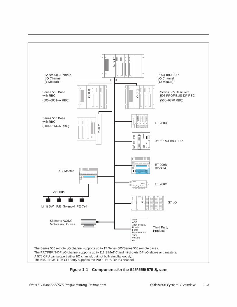
Series 505 System Overview 1-3SIMATIC 545/555/575 Programming Reference
Series 505 RemoteI/O Channel (1 Mbaud)
PROFIBUS-DPI/O Channel(12 Mbaud)
Third PartyProducts
Series 505 Base with505 PROFIBUS-DP RBC
The Series 505 remote I/O channel supports up to 15 Series 505/Series 500 remote bases.
CPU
C
RBC
RBC
S7 I/O
ET 200BBlock I/O
95U/PROFIBUS-DP
ET 200U
ET 200C
Series 505 Basewith RBC
Series 500 Basewith RBC
(505–6851–A RBC)
(500–5114–A RBC)
(505–6870 RBC)
RBC
The PROFIBUS-DP I/O channel supports up to 112 SIMATIC and third-party DP I/O slaves and masters.
Siemens AC/DCMotors and Drives
A 575 CPU can support either I/O channel, but not both simultaneously.The 545–1103/–1105 CPU only supports the PROFIBUS-DP I/O channel.
ABBAEGAllen-BradleyBoschFestoMannesmannTurkVickersetc.
ASI Master
Limit SW P/B Solenoid PE Cell
ASI Bus
Figure 1-1 Components for the 545/555/575 System

Series 505 System Overview1-4 SIMATIC 545/555/575 Programming Reference
The 545, 555, and 575 Systems (continued)
When you use the PROFIBUS-DP I/O channel, you can connect up to 32PROFIBUS-DP-compatible I/O slaves and masters with the 545–1103/–1105CPUs, or up to 112 slaves and masters with the 545–1104/–1106, 555, and575 CPUs.
NOTE: Special Function modules cannot be installed on the PROFIBUS-DPI/O channel.
The response of output points on ET200B and other PROFIBUS-DP slavedevices that are connected to the PROFIBUS-DP I/O channel is differentfrom the response of devices on the normal 505 I/O channel.
If network communications are interrupted, or if you power-cycle the masterCPU, the outputs of most PROFIBUS-DP slaves momentarily transition to azero state when communications are reestablished.
! WARNINGThe outputs of most PROFIBUS-DP slaves momentarily transition to a zerostate when communications are reestablished following a power cycle orinterruption in network communications.
If output points are expected to retain the last valid state received from thecontrolling device prior to the communication interruption, erratic operation ofyour process may result. This could cause unpredictable operation by thecontroller or network, which could result in death or serious injury topersonnel, and/or damage to equipment.
Follow the solutions listed below to avoid unexpected process operation.
• Define your system to withstand the output transition to a zero statewhen communications are reestablished following a power cycle orinterruption in network communications.
• Use slaves that support the “Fail-Safe” feature, which is a recentenhancement to the PROFIBUS-DP Standard DIN 19245 Part 3. TheFail-Safe feature, combined with an appropriately designed controlprogram, can prevent the slave outputs from transitioning to zero whenyou power up the CPU or reestablish network communications. The505–6870 Remote Base Controller provides the Fail-Safe feature.
If fail-safe slaves are not used, you must ensure successful process controlthrough your program design or other external means in the event of anerror condition such as a loss of communication to slave devices due to cablebreaks or a power-cycle of the controlling CPU.
For additional information, contact your distributor.
PROFIBUS-DP I/O
Output Responseon PROFIBUS-DPSlave Devices

Series 505 System Overview 1-5SIMATIC 545/555/575 Programming Reference
You must assign the I/O point and slot numbers from the I/O ConfigurationChart on your programming device. The programmable controller does notupdate discrete or word I/O points in non-configured I/O modules. Refer toyour TISOFT user manual for instructions about configuring the I/O.
For the 545–1103/–1105, a maximum of 1024 I/O points can be assigned. Upto 4096 control relays are available.
For the 545–1104/–1106, a maximum of 2048 I/O points can be assigned. Ofthese, up to 1024 can be discrete or word points, which must be numbered1–1024. The next 1024 points are discrete only. Up to 32,768 control relaysare available.
For the 555 CPUs, a maximum of 8192 I/O points can be assigned in anymix of discrete and word I/O. Up to 32,768 control relays are available.
For the 575 CPUs, a maximum of 8192 I/O points can be assigned. Up to23,552 control relays are available.
You do not need to assign I/O point numbers consecutively. For example, ina remote system, Base 2 can be assigned I/O points 897–960. If a base isconfigured and the modules in the base do not match the configuration, theprogrammable controller logs a non-fatal error. Misconfigured modules arenot accessed by your program. Inputs are read as 0; outputs are ignored.
A Special Function Module is divided into the I/O portion and the specialfunction portion. When a Special Function Module is inserted into a system,the special function portion of the module is automatically logged in, andcan send data to and receive data from the controller.
NOTE: You must configure the I/O portion so that the controller updates theI/O points. Non-special function modules are not logged in automatically.
Assigning I/OPoint Numbers
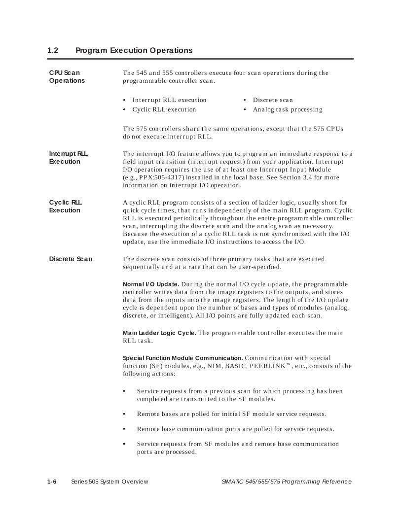
Series 505 System Overview1-6 SIMATIC 545/555/575 Programming Reference
1.2 Program Execution Operations
The 545 and 555 controllers execute four scan operations during theprogrammable controller scan.
• Interrupt RLL execution • Discrete scan• Cyclic RLL execution • Analog task processing
The 575 controllers share the same operations, except that the 575 CPUsdo not execute interrupt RLL.
The interrupt I/O feature allows you to program an immediate response to afield input transition (interrupt request) from your application. InterruptI/O operation requires the use of at least one Interrupt Input Module(e.g., PPX:505-4317) installed in the local base. See Section 3.4 for moreinformation on interrupt I/O operation.
A cyclic RLL program consists of a section of ladder logic, usually short forquick cycle times, that runs independently of the main RLL program. CyclicRLL is executed periodically throughout the entire programmable controllerscan, interrupting the discrete scan and the analog scan as necessary.Because the execution of a cyclic RLL task is not synchronized with the I/Oupdate, use the immediate I/O instructions to access the I/O.
The discrete scan consists of three primary tasks that are executedsequentially and at a rate that can be user-specified.
Normal I/O Update. During the normal I/O cycle update, the programmablecontroller writes data from the image registers to the outputs, and storesdata from the inputs into the image registers. The length of the I/O updatecycle is dependent upon the number of bases and types of modules (analog,discrete, or intelligent). All I/O points are fully updated each scan.
Main Ladder Logic Cycle. The programmable controller executes the mainRLL task.
Special Function Module Communication. Communication with specialfunction (SF) modules, e.g., NIM, BASIC, PEERLINK�, etc., consists of thefollowing actions:
• Service requests from a previous scan for which processing has beencompleted are transmitted to the SF modules.
• Remote bases are polled for initial SF module service requests.
• Remote base communication ports are polled for service requests.
• Service requests from SF modules and remote base communicationports are processed.
CPU ScanOperations
Interrupt RLLExecution
Cyclic RLLExecution
Discrete Scan

Series 505 System Overview 1-7SIMATIC 545/555/575 Programming Reference
Each SF module that requires service increases the scan time, dependingupon the type of module and task. Each type of module is allowed a certainnumber of service requests per scan. Once these are completed, this functionis terminated. Some service requests can be deferred, and these areprocessed during the analog task time slice described in Figure 1-2.
RLLI/O
update
SFmoduleaccess
Analogtasks
Analog tasks are also executedduring windows occurring in the
discrete scan.
CyclicRLL
Cyclic RLL interrupts the discrete scan asnecessary to complete its cyclical execution.
Main
InterruptRLL
Interrupt RLL interrupts all processes below wheneveran interrupt module sends an interrupt request.
Figure 1-2 Discrete Scan Sequence

Series 505 System Overview1-8 SIMATIC 545/555/575 Programming Reference
Program Execution Operations (continued)
The analog portion of the scan is composed of five general types of tasks(Figure 1-3), which are cyclical or non-cyclical in their execution.
Analog tasks are guaranteed execution once per scan, following the discretescan, provided there is processing to be done. Analog tasks are alsoprocessed during windows of suspended activity that occur during thenormal I/O and SF portions of the scan. RLL execution is not interrupted byanalog tasks.
You can adjust the amount of time spent per controller scan for all analogtasks, except diagnostics, with a programming unit and using AUXFunction 19. The time allocation for a given analog task is referred to as itstime slice.
Cyclic and interrupt RLL interruptthe analog tasks as necessary.
Diagnostics*
*Enabled for execution at the completion of the discrete scan.
LoopsAnalogalarms
SFprograms
Servicerequests
Cyclic/Interrupt
RLL
RBEevent
detection
Figure 1-3 Analog Task Scan Sequence
The following types of processes are executed cyclically. Each has a samplerate which determines how often it is executed.
• Loops
• Analog alarms
• Cyclic SF programs
The programmable controller has a separate task to execute each type ofcyclic process. When enabled, each cyclic process is placed in the executionqueue that is managed by the task responsible for executing that type ofprocess.
Analog TaskProcessing
Cyclic AnalogTasks

Series 505 System Overview 1-9SIMATIC 545/555/575 Programming Reference
The cyclic processes are time-ordered in their individual queues according towhen each process is rescheduled for execution, relative to the other cyclicprocesses within the same queues. The process with the highest priority(closest to overrunning) is executed first. The process is executed until it iscompleted or until the time specified for that particular task’s time sliceexpires. If the executing process is completed before the time slice expires,the process with the next highest priority is executed. If the time sliceexpires before the process is completed, the process (and the task) is put onhold in its current position.
The programmable controller then advances to the next analog task. Whenthe programmable controller sequences through its operations and returnsto an analog task with a cyclic process on hold, the process resumesexecution from the hold point, unless a higher priority process wasscheduled since the last respective time slice. If a process in a cyclic timeslice is not finished executing when it is scheduled to execute again, anoverrun flag is set.
Restricted SF programs, which are called by loops or analog alarms, areexecuted from within the loop or analog alarm tasks. Therefore, theirexecution time is included within the loop or analog alarm time slice.
NOTE: For CPUs that support PowerMath, while a compiled SF program isexecuting, a higher priority process on the queue will not execute until theprogram terminates.
SF subroutines, which are called by SF programs or other SF subroutines,are processed during the calling program’s time slice.
The following types of processes are executed non-cyclically:
• Priority/Non-priority SF programs.
• RLL-requested SF subroutines.
• Service request messages.
• Report by Exception (RBE) event detection.
• Run-time diagnostics.
Non-cyclic AnalogTasks

Series 505 System Overview1-10 SIMATIC 545/555/575 Programming Reference
Program Execution Operations (continued)
Priority and Non-Priority SF Programs are non-cyclic processes that are queuedwhen the SFPGM RLL box instruction receives power flow. There is ananalog task that executes priority SF programs, and another analog taskthat executes non-priority SF programs. These processes are executed in theorder that they are queued in the appropriate task’s execution queue. Whenthe programmable controller completes one of these processes, it removesthe process from the respective queue and turns on the SFPGM output.There are no overrun flags associated with these processes.
RLL-requested SF Subroutines are queued into one of two SFSUB queues whenthe SFSUB RLL box instruction receives power flow. One queue handlesSFSUB 0 instructions and the other handles all other SFSUB instructions.
Service Requests received from the communication ports are placed on one oftwo communications queues. Read and write commands are placed on thepriority communication queue for fastest response. Commands that mayrequire several scans to complete, e.g., program edits and the TISOFT FINDfunction, are placed in a non-priority communications queue.
Report By Exception event detection task only executes when theprogrammable controller is used with SIMATIC� PCS�, Release 3.0 orlater. The RBE event detection task monitors PCS-defined process eventsand notifies PCS when an event is detected.
Run-time Diagnostics are enabled for execution at the completion of thediscrete scan. The time slice for diagnostics is 1 ms and cannot be changed.
The 545/555/575 scan is defined as the time between normal I/O updates.You can set the scan for the controller as follows.
• Fixed — The programmable controller starts a new discrete scan at thespecified time interval. The controller executes the discrete scan onceand then cycles to the analog scan portion, executing the analog tasksat least one time. If the analog tasks are completed within the specifiedtime, the controller goes into a loop mode (processing analog tasks oridling) until time to start the next scan.
A scan overrun status bit is set (bit 14 in Status Word 1) if the totalexecution time for the discrete scan portion and the first execution ofthe analog scan portion exceeds the fixed scan time.
• Variable — The programmable controller executes all tasks once andthen starts a new scan. All discrete and analog tasks are guaranteedone execution per scan. Specify variable scan for the fastest possibleexecution of the discrete scan.
Setting the Scan

Series 505 System Overview 1-11SIMATIC 545/555/575 Programming Reference
• Variable with upper limit — The programmable controller executes thediscrete scan once and then executes the analog tasks. The controllerremains in the analog portion of the scan as long as there are analogtasks to be done. When the upper time limit expires, or no analog tasksrequire processing, a new scan is begun.
The analog scan portion is executed at least one time. A scan overrunstatus bit is set if the total execution time for the discrete scan portionand the first execution of the analog scan portion exceeds the upperlimit.
Cycle time for the cyclic RLL can be a fixed value or a user-specifiedvariable. As a variable, the cycle time can be changed by logic in yourapplication program. If the cyclic RLL completes execution in less than thespecified cycle time, execution does not resume until the next cycle begins.The programmable controller scan time is extended by the amount of timeto execute the cyclic RLL multiplied by the number of times the cyclic RLLis executed during the programmable controller scan.
The timing relationship of the scan operations is shown in Figure 1-4. Referto the Appendix C for details about how to configure the time slices.
Cyclic RLLexecution*
Discrete scan
Time
Analog scan
One programmable controller scan
* Cyclic RLL program is executed to completion each time it runs.
Interrupt RLLexecution
ÉÉ
ÉÉÉÉ
ÉÉ
Figure 1-4 Timing Relationship of the Controller Scan Operations

Data Representation 2-1SIMATIC 545/555/575 Programming Reference
Chapter 2
Data Representation
2.1 Definitions 2-2. . . . . . . . . . . . . . . . . . . . . . . . . . . . . . . . . . . . . . . . . . . . . . . . . . . . . . . . . . . . . . . . . . . . . . Byte 2-2. . . . . . . . . . . . . . . . . . . . . . . . . . . . . . . . . . . . . . . . . . . . . . . . . . . . . . . . . . . . . . . . . . . . . . . . . . . Word 2-2. . . . . . . . . . . . . . . . . . . . . . . . . . . . . . . . . . . . . . . . . . . . . . . . . . . . . . . . . . . . . . . . . . . . . . . . . . . Long Word 2-2. . . . . . . . . . . . . . . . . . . . . . . . . . . . . . . . . . . . . . . . . . . . . . . . . . . . . . . . . . . . . . . . . . . . . Image Register 2-2. . . . . . . . . . . . . . . . . . . . . . . . . . . . . . . . . . . . . . . . . . . . . . . . . . . . . . . . . . . . . . . . . I/O Point 2-2. . . . . . . . . . . . . . . . . . . . . . . . . . . . . . . . . . . . . . . . . . . . . . . . . . . . . . . . . . . . . . . . . . . . . . .
2.2 Integers 2-3. . . . . . . . . . . . . . . . . . . . . . . . . . . . . . . . . . . . . . . . . . . . . . . . . . . . . . . . . . . . . . . . . . . . . . . . Signed 16-Bit Integers 2-3. . . . . . . . . . . . . . . . . . . . . . . . . . . . . . . . . . . . . . . . . . . . . . . . . . . . . . . . . . . Unsigned 16-Bit Integers 2-4. . . . . . . . . . . . . . . . . . . . . . . . . . . . . . . . . . . . . . . . . . . . . . . . . . . . . . . . . Signed 32-Bit Integers 2-4. . . . . . . . . . . . . . . . . . . . . . . . . . . . . . . . . . . . . . . . . . . . . . . . . . . . . . . . . . .
2.3 Real Numbers 2-5. . . . . . . . . . . . . . . . . . . . . . . . . . . . . . . . . . . . . . . . . . . . . . . . . . . . . . . . . . . . . . . . . .
2.4 Binary-Coded Decimal 2-6. . . . . . . . . . . . . . . . . . . . . . . . . . . . . . . . . . . . . . . . . . . . . . . . . . . . . . . . . .
2.5 Format for an Address Stored in a Memory Location 2-7. . . . . . . . . . . . . . . . . . . . . . . . . . . . . .

Data Representation2-2 SIMATIC 545/555/575 Programming Reference
2.1 Definitions
The terms listed below are used throughout this manual and have thefollowing meanings.
A byte consists of 8 contiguous bits.
1 8Most
significant bitLeastsignificant bit
A word consists of 2 contiguous bytes, 16 bts.
1 16
Byte 0 Byte 1
Mostsignificant bit
Leastsignificant bit
For example, the contents of V-Memory word V100 occupy 16 contiguousbits; the word output WY551 occupies 16 contiguous bits.
A long word consists of 2 contiguous words, 32 bits, that represent a singlevalue.
1
Byte 0 Byte 1
32
Byte 2 Byte 3
Word 0 Word 1
Most significant word Least significant word
For example, the contents of V-Memory long word V693 occupy twocontiguous words (32 bits), V693 and V694. The next available address isV695, which can represent a word (16 bits) or another long word (32 bits).
The image register is a reserved memory area used to store the value of alldiscrete (on/off) and word I/O data. Discrete I/O data is contained in thediscrete image register. Word I/O data is stored in the word image register.See Section 3.1 for a more complete discussion of the function of the imageregister.
An I/O point consists of an I/O type and a reference number that represent alocation in the image register. An I/O point that represents a discrete bit inthe discrete image register is identified as an X or Y I/O type. An I/O pointthat represents a word in the word image register is identified as a WX orWY I/O type.
Byte
Word
Long Word
Image Register
I/O Point

Data Representation 2-3SIMATIC 545/555/575 Programming Reference
2.2 Integers
Signed integers are stored as 16-bit words in the two’s complement formatas shown in Figure 2-1. The 16-bit format allows you to store values rangingfrom –32,768 to +32,767 (decimal integer values). When bit 1 (the sign bit)is 0, the number is positive; when bit 1 is 1, the number is negative.
0 1 1 1 1 1 1 1 1 1 1 1 1 1 1 1
1 0 0 0 0 0 0 0 0 0 0 0 0 0 0 0
0 0 0 0 0 0 0 0 0 0 0 0 0 0 0 0
0 0 0 0 0 0 0 0 0 0 0 0 0 0 0 1
1 0 0 0 0 0 0 0 0 0 0 0 0 0 0 1
1 1 1 1 1 1 1 1 1 1 1 1 1 1 1 0
1 1 1 1 1 1 1 1 1 1 1 1 1 1 1 1
1 2 3 4 5 6 7 8 9 10 11 12 13 14 15 16
0 0 0 0 0 0 0 0 0 0 0 0 0 0 1 0 = +2
= +1
= +0
= –1
= –2
= –32767
= –32768
= +32767
Mostsignificantbit
Signbit
Leastsignificantbit
Figure 2-1 Format of Signed 16-Bit Integers
Signed 16-BitIntegers

Data Representation2-4 SIMATIC 545/555/575 Programming Reference
Integers (continued)
You can display data on your programming unit as an unsigned integer. The16-bit format allows you to display integer values ranging from 0 to 65535as shown in Figure 2-2.
0 0 0 0 0 0 0 0 0 0 0 0 0 0 0 0
0 0 0 0 0 0 0 0 0 0 0 0 0 0 0 1
1 1 1 1 1 1 1 1 1 1 1 1 1 1 1 0
1 1 1 1 1 1 1 1 1 1 1 1 1 1 1 1
1 2 3 4 5 6 7 8 9 10 11 12 13 14 15 16
0 0 0 0 0 0 0 0 0 0 0 0 0 0 1 0
= 65535= 65534
= 2
= 1
= 0
Mostsignificantbit
Leastsignificantbit
Figure 2-2 Format of Unsigned 16-Bit Integers
Thirty-two bit signed long word integers are stored as 32-bit long words inthe two’s complement format, as shown in Figure 2-3:
0 0 1 0 0 0 1 1 0 1 0 0 1 1 0 0
0 0 0 0 1 0 0 0 0 1 1 1 1 0 0 01 2 3 4 5 6 7 8 9 10 11 12 13 14 15 16Sign bit
17 18 19 20 21 22 23 24 25 26 27 28 29 30 31 32
Word 0
Word 1 142,091,084
Decimalequivalent:
Figure 2-3 Format of Signed 32-Bit Integers
Unsigned 16-BitIntegers
Signed 32-BitIntegers
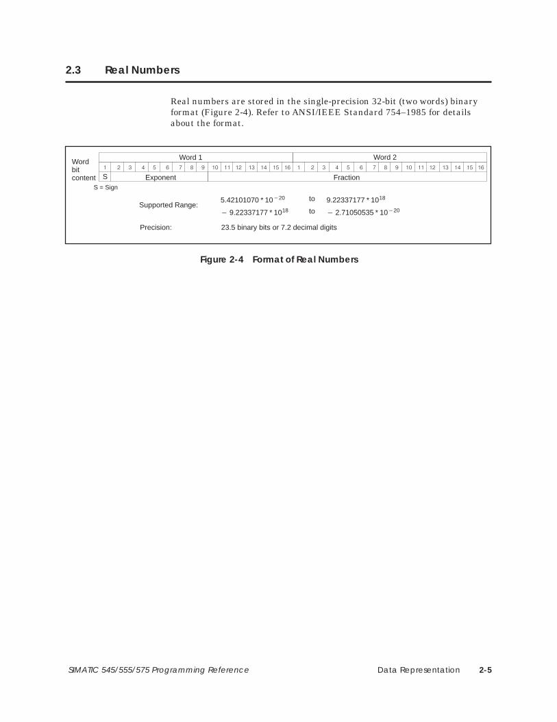
Data Representation 2-5SIMATIC 545/555/575 Programming Reference
2.3 Real Numbers
Real numbers are stored in the single-precision 32-bit (two words) binaryformat (Figure 2-4). Refer to ANSI/IEEE Standard 754–1985 for detailsabout the format.
� � � � � � � �� �� �� �� �� �� ��
Word 1� � � � � � � �� �� �� �� �� �� ��
Word 2
S
5.42101070 * 10�20 9.22337177 * 1018to
� 9.22337177 * 1018� 2.71050535 * 10�20to
Supported Range:
Wordbitcontent FractionExponent
S = Sign
Precision: 23.5 binary bits or 7.2 decimal digits
Figure 2-4 Format of Real Numbers

Data Representation2-6 SIMATIC 545/555/575 Programming Reference
2.4 Binary-Coded Decimal
Individual BCD digits from a BCD field device are stored in a word ingroups of four bits. For example, the number 0582 is stored as shown inFigure 2-5:
50 8 2
1 2 3 4 5 6 7 8 9 10 11 12 13 14 15 16
0 0 0 0 0 1 0 1 1 0 0 0 0 0 1 0Mostsignificantbit
Leastsignificantbit
Figure 2-5 Example of Binary-Coded Decimal Values
Each digit of the BCD value must be less than or equal to 9. The binaryvalues 1010, 1011, 1100, 1101, 1110, and 1111 are invalid.
Normally, you would convert a BCD value to the binary format, as describedin Section 6.9, using the resulting value elsewhere in your program.

Data Representation 2-7SIMATIC 545/555/575 Programming Reference
2.5 Format for an Address Stored in a Memory Location
The Load Address (LDA) instruction allows you to store a memory addressin a memory location. A description of LDA and examples of its usage aregiven in Section 6.26.
When you use LDA to store an address in a memory location, one long wordis required, as shown below.
Memory type
Byte 0 Byte 1 Byte 2 Byte 3
Word offset
The memory data type is contained in byte 0. The word offset relative to thebase address for the data type is contained in bytes 1–3. Data type codes arelisted in Table 2-1.
Table 2-1 Data Type Codes for Controller Memory Areas
Memory Area Data Type(Hex) Memory Area Data Type
(Hex)
Subroutine work area 00 Application G Global Variables E8
Variable 01 Application H Global Variables E7
Constant 02 Application I Global Variables E6
Word Input 09 Application J Global Variables E5
Word Output 0A Application K Global Variables E4
Timer/Counter Preset 0E Application L Global Variables E3
Timer/Counter Current 0F Application M Global Variables E2
Drum Step Preset 10 Application N Global Variables E1
Drum Step Current 11 Application O Global Variables E0
Drum Count Preset 12 Application P Global Variables DF
Status Word 1A Application Q Global Variables DE
Drum Count Current 1B Application R Global Variables DD
VME A24 Space D3 Application S Global Variables DC
VME A16 Space D4 Application T Global Variables DB
My Global Variables EF Application U Global Variables DA
Application A Global Variables EE Application V Global Variables D9
Application B Global Variables ED Application W Global Variables D8
Application C Global Variables EC Application X Global Variables D7
Application D Global Variables EB Application Y Global Variables D6
Application E Global Variables EA Application Z Global Variables D5
Application F Global Variables E9

Data Representation2-8 SIMATIC 545/555/575 Programming Reference
Format for an Address Stored in a Memory Location (continued)
The format for logical addresses in the subroutine work areas differs fromthe other data types, as shown below.
Memory type
Byte 0 Byte 1 Byte 2 Byte 3
Parameternumber – 1
Subroutinenumber – 1
For example, WY77 is stored in V100 and V101 as shown in Figure 2-6. Thecode for the WY data type is 0A. The decimal offset for the 77th word is 76,which is 00004C in hex.
0A00
4C00
WYMemory type (Hex)
00 00 4CV100
V101
Word offset gives the position in Hex:
WY1 = 0000 (Hex) = 0 (Dec) (1st position)WY2 = 0001 (Hex) = 1 (Dec) (2nd position)
WY77 = 004C (Hex) = 76 (Dec) (77th position)
Address Offset Offset Position(Hex) (Dec)
Figure 2-6 Example of Storing an Address
NOTE: An address always references a word boundary.
! WARNINGThe address that is copied to the destination is a logical, not a physical,address. The misuse of this address could cause an unsafe condition thatcould result in death or serious injury to personnel, and/or damage toequipment.Do not use this address as a pointer within an external subroutine.
NOTE: The data type codes are provided to give assistance when you decodeinformation displayed in TISOFT. You do not have to enter a data typewhen you program an LDA. For example, to load V-Memory address V15,enter V15 in field A of the LDA instruction, not 0100 000E.

I/O Concepts 3-1SIMATIC 545/555/575 Programming Reference
Chapter 3
I/O Concepts
3.1 Reading and Updating the I/O 3-2. . . . . . . . . . . . . . . . . . . . . . . . . . . . . . . . . . . . . . . . . . . . . . . . . . . Discrete Image Register 3-3. . . . . . . . . . . . . . . . . . . . . . . . . . . . . . . . . . . . . . . . . . . . . . . . . . . . . . . . . Word Image Register 3-5. . . . . . . . . . . . . . . . . . . . . . . . . . . . . . . . . . . . . . . . . . . . . . . . . . . . . . . . . . . .
3.2 Normal I/O Updates 3-6. . . . . . . . . . . . . . . . . . . . . . . . . . . . . . . . . . . . . . . . . . . . . . . . . . . . . . . . . . . . Discrete Control 3-6. . . . . . . . . . . . . . . . . . . . . . . . . . . . . . . . . . . . . . . . . . . . . . . . . . . . . . . . . . . . . . . . Analog Control 3-6. . . . . . . . . . . . . . . . . . . . . . . . . . . . . . . . . . . . . . . . . . . . . . . . . . . . . . . . . . . . . . . . .
3.3 High Speed I/O Updates 3-8. . . . . . . . . . . . . . . . . . . . . . . . . . . . . . . . . . . . . . . . . . . . . . . . . . . . . . . . Immediate I/O 3-8. . . . . . . . . . . . . . . . . . . . . . . . . . . . . . . . . . . . . . . . . . . . . . . . . . . . . . . . . . . . . . . . . . Modules that Support Immediate I/O 3-10. . . . . . . . . . . . . . . . . . . . . . . . . . . . . . . . . . . . . . . . . . . . Configuring Immediate I/O 3-10. . . . . . . . . . . . . . . . . . . . . . . . . . . . . . . . . . . . . . . . . . . . . . . . . . . . . .
3.4 Interrupt I/O Operation 3-11. . . . . . . . . . . . . . . . . . . . . . . . . . . . . . . . . . . . . . . . . . . . . . . . . . . . . . . . . . Overview 3-11. . . . . . . . . . . . . . . . . . . . . . . . . . . . . . . . . . . . . . . . . . . . . . . . . . . . . . . . . . . . . . . . . . . . . . . Configuring the Interrupt Input Module 3-11. . . . . . . . . . . . . . . . . . . . . . . . . . . . . . . . . . . . . . . . . . .
3.5 Control Relays 3-13. . . . . . . . . . . . . . . . . . . . . . . . . . . . . . . . . . . . . . . . . . . . . . . . . . . . . . . . . . . . . . . . . . Using Retentive and Non-retentive Control Relays 3-14. . . . . . . . . . . . . . . . . . . . . . . . . . . . . . . .

I/O Concepts3-2 SIMATIC 545/555/575 Programming Reference
3.1 Reading and Updating the I/O
In normal operation the controller updates outputs, reads inputs, and solvesthe user application program. The I/O update is shown in Figure 3-1. TheSeries 505 controllers have reserved memory areas for storing the value ofall discrete and word I/O points. Discrete I/O values are contained in thediscrete image register, which provides storage for all discrete (on/off) I/Opoints. Word values are stored in the word image register, which providesstorage for word and analog data.
Image register
ControllerPowerSupply
Inputmodule
Outputmodule
Limitswitch
1
1
X3 Y9
Pilotlight
Controller scan
Normal I/O updateController writesoutputs, reads inputs
RLL execution
Figure 3-1 Image Register Update
Following the I/O update, the image registers hold the latest value of alldiscrete and word inputs. As the user program is executed, new values fordiscrete/word outputs are stored in the image registers. At the completion ofthe user program, the controller begins a new cycle. The I/O is updated: theresults of the last program execution are written from the image registers tothe discrete/word outputs, and new values are read for use in the userprogram. Then the user program is executed.

I/O Concepts 3-3SIMATIC 545/555/575 Programming Reference
An area of memory within the controller called the discrete image register(Figure 3-2) is reserved for maintaining the status of all discrete inputs andoutputs.
As a troubleshooting tool, you can use a programming device to force an I/Opoint on or off. A record of the forced state of a discrete I/O point is kept bythe force attribute bit, also shown in Figure 3-2. There is a one-bit locationfor each of the discrete I/O points. If a discrete I/O point is forced to aparticular state, that point remains in that state and does not change untilit is forced to the opposite state or is unforced. A power cycle does not alterthe value of a forced discrete I/O point as long as the controller battery isgood.
1234
5678
10
11
9
1234
5678
10
11
9
Discrete image register
X or Y
Force attribute bit
X or Y
Figure 3-2 Discrete Image Register
Discrete ImageRegister

I/O Concepts3-4 SIMATIC 545/555/575 Programming Reference
Reading and Updating the I/O (continued)
The size of the discrete image register depends upon your controller model(see Table 3-1). Although the discrete and word I/O modules have separateimage registers, they are used in the same physical I/O slots. Therefore, thetotal number of both discrete and word I/O cannot exceed the number listedfor your controller model.
Table 3-1 Discrete/Word I/O Permitted
CPU Model Discrete / Word I/O
PPX:545–1103/–1105 1024
PPX:545–1104/–1106 2048/1024*
All 555 CPUs 8192
All 575 CPUs 8192
* The 545–1104/–1106 CPUs support 2048 points. Of these, 1024 can be any combination ofdiscrete/word points. The second 1024 points are discrete only.
! CAUTIONXs and Ys use the same discrete image register .
If you assign an input module to an X image register point and an outputmodule to the same Y image register point, your program may not be able toaffect the output module’ s actions.
Do not assign the same reference number to both an input (X) and an output (Y).

I/O Concepts 3-5SIMATIC 545/555/575 Programming Reference
The word image register (Figure 3-3) is an area of memory within thecontroller that is reserved for holding the contents of all 16-bit word inputsand outputs. The size of the word image register depends upon yourcontroller model. The total number of discrete and word I/O cannot exceedthe number listed for your controller model.
As a troubleshooting tool, word I/O can be forced. The record of the forcedstate of word I/O is kept by a force attribute bit, shown in Figure 3-3. Thereis a one-bit location for each of the word I/O points. If an I/O word is forced,then the value contained within that word does not change until the wordeither is forced to a different value or is unforced. A power cycle does notalter the value of a forced I/O word as long as the controller battery is good.
WX or WYBit WX or WY
12345678
1011
9
1 2 3 4 5 6 7 8 9 1110 12 13 14 15 1612345678
1011
9
Word image register Force attribute bit
Figure 3-3 Word Image Register
! CAUTIONWXs and WYs use the same word image register .
If you assign an input module to an WX image register point and an outputmodule to the same WY image register point, your program may not be able toaffect the output module’ s actions.
Do not assign the same reference number to both an input (WX) and an output (WY).
Word ImageRegister

I/O Concepts3-6 SIMATIC 545/555/575 Programming Reference
3.2 Normal I/O Updates
To relate the hardwired connections on the equipment that you arecontrolling to the program inputs and outputs, you need to focus on thefunction of the image register. For normal I/O updates, the interfacebetween the software RLL program and the physical hardware occurswithin the image register. Refer to Figure 3-4 for an example of the discreteoperation in which a limit switch controls the state of a pilot light.
Analog control is similar in operation to discrete control except that data istransmitted as 16-bit words. An analog input signal is converted by theanalog input module into a 16-bit digital word. This word of data is writtento the word image register.
The controller solves the RLL logic, executing all the necessary tasksrelating to the data. If controlling an analog output is the function of theprogram, then a word of data is written to the word image register.
The controller writes the word from the image register to the analog outputmodule during the normal I/O cycle portion of the scan. The moduleconverts the 16-bit digital word into an analog signal, and sends the analogsignal to the appropriate field device.
Discrete Control
Analog Control

I/O Concepts 3-7SIMATIC 545/555/575 Programming Reference
LS 24 PL 99
Point Slot
Slot 1
Slot 2
1 2 3 4 5 6 7 8number Number
Y9 Y10 Y11 Y12 Y13 Y14 Y15 Y16
X65 X66 X67 X68 X69 X70 X71 X72
Assigned I/O identifiers
( )X69 Y16
Slot 3...
. . .
Input
Point 5 in
Input module Output module
Output
Point 8 inSlot 1 = Y16 = high
Slot 1 = X69 = High
PL 99
Controller
X69
1
Y16
0
X69
1
Y16
1
The hardware has been installed in this way:
Limit Switch #24 is connected to Point 5 of the inputmodule located in Slot 2.
Pilot Light #99 is connected to Point 8 of the outputmodule located in Slot 1.
These I/O assignments have been made using theprogramming unit:
X69 has been assigned to Point 5 in Slot 2.Y16 has been assigned to Point 8 in Slot 1.
The input module detects when Limit Switch #24closes.
Slot 2 Slot 1
LS 24
Point 8Point 5
( )X69 Y16
Discreteimage registers
Discreteimage registers
The controller writes a 1 to Y16 in the discreteimage register.
During the next I/O update, the controller writesthe 1 from Y16 in the image register to the outputmodule. The output module then turns on power to Pilot Light #99.
Note that if Limit Switch #24 remains on, the controllerstill writes a 1 to X69 in the discrete image registerduring this I/O update (not shown in the diagram).
During the next I/O update, the controller readsthe state of the input point from the module, andwrites a 1 to X69 in the discrete image register.Note that Y16 is off, and so the controller writes a 0 from Y16 to the output module during thisI/O update (not shown in the diagram).
The controller solves the RLL logic. Since X69 ison, Y16 is turned on.
Figure 3-4 Relation of Hardwired Field Devices and the RLL Program

I/O Concepts3-8 SIMATIC 545/555/575 Programming Reference
3.3 High Speed I/O Updates
The immediate I/O feature allows your RLL application program to accessan I/O point in a local I/O module multiple times per controller scan. Thisfeature enables you to sample fast-changing inputs more often, providing afaster response to the application.
Figure 3-5 illustrates the operation for immediate contacts and immediatecoils.
• Use an immediate contact when you want to read an input pointdirectly from the input module as part of the power flow computation.The input discrete image register is not updated as the result of animmediate contact.
• Use an immediate coil when you want to simultaneously write theresult of a power flow computation to the output discrete image registeras well as to the output module.
ControllerPowerSupply
Inputmodule
Outputmodule
1
X3 Y9
ImageRegister
LimitSwitch Pilot
Light
I I
Figure 3-5 Immediate I/O Update
Immediate I/O

I/O Concepts 3-9SIMATIC 545/555/575 Programming Reference
Figure 3-6 illustrates the operation of the IORW (immediate I/O read/write)instruction. For further discussion on immediate I/O read/write, see section6.24.
• Use an IORW instruction specifying a discrete input image registeraddress (e.g., X1) or a word input image register address (e.g., WX50) toread a block of I/O point values from a module into the referencedimage register. The entire block must be contained in a single module.
• Use an IORW instruction specifying a discrete output image registeraddress (e.g., Y17) or a word output image register address (e.g., WY22)to write a block of I/O point values from the referenced image registerto a module. The entire block must be contained in a single module.
PowerSupply
Controller InputModule
OutputModule
IORWA: X1N: 8
C1 C2
IORWA: WY22N: 2
C1 C2
Discrete IR
X1 0X2 1X3 1X4 0X5 0X6 1X7 0X8 1
Word IR
WY22 2WY23 5
⇐
⇒
⇐⇐⇐⇐⇐⇐⇐
⇒ ⇒⇒ ⇒⇒
01100101
25
Figure 3-6 IORW Instruction
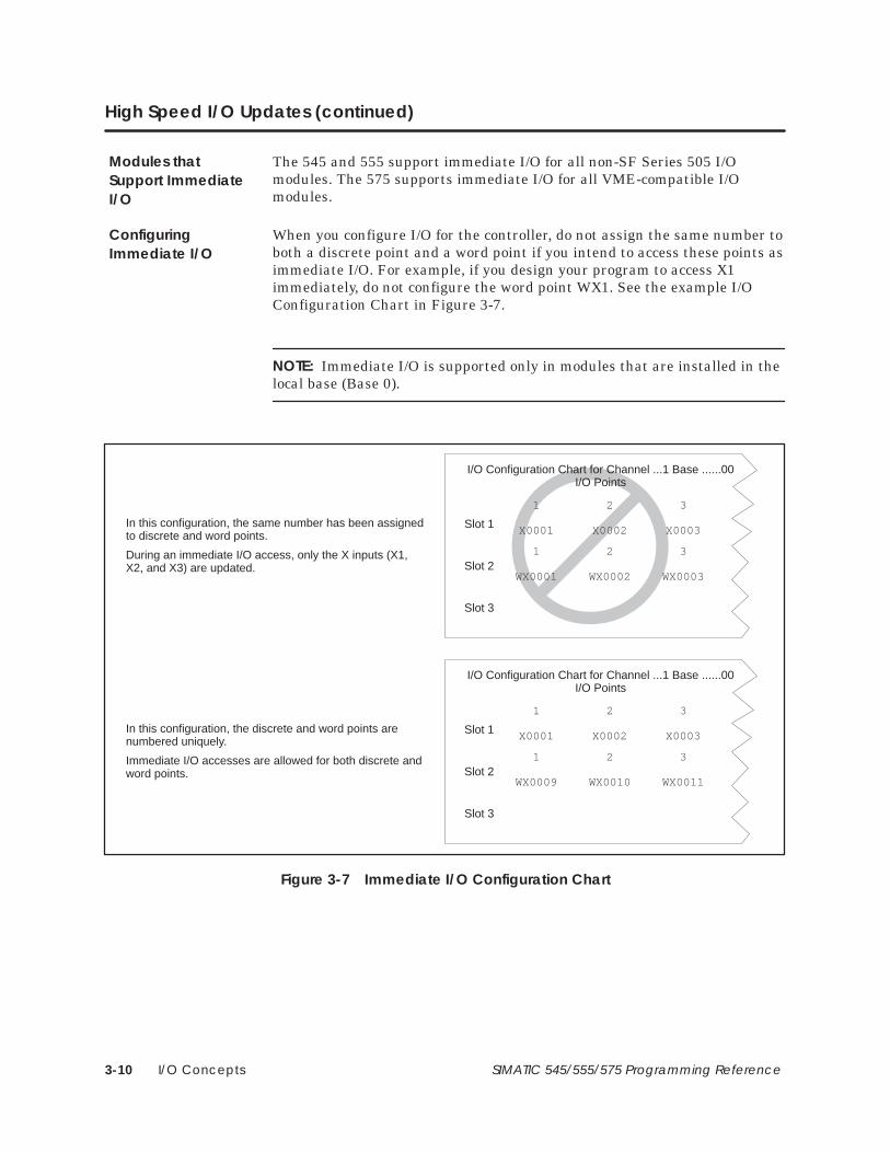
I/O Concepts3-10 SIMATIC 545/555/575 Programming Reference
High Speed I/O Updates (continued)
The 545 and 555 support immediate I/O for all non-SF Series 505 I/Omodules. The 575 supports immediate I/O for all VME-compatible I/Omodules.
When you configure I/O for the controller, do not assign the same number toboth a discrete point and a word point if you intend to access these points asimmediate I/O. For example, if you design your program to access X1immediately, do not configure the word point WX1. See the example I/OConfiguration Chart in Figure 3-7.
NOTE: Immediate I/O is supported only in modules that are installed in thelocal base (Base 0).
Slot 1
I/O Configuration Chart for Channel ...1 Base ......00I/O Points
Slot 1
Slot 2
Slot 3
WX0009 WX0010 WX0011
1 2 3
X0001 X0002 X0003
1 2 3
Slot 2
Slot 3
1 2 3
In this configuration, the same number has been assignedto discrete and word points.
During an immediate I/O access, only the X inputs (X1,X2, and X3) are updated.
In this configuration, the discrete and word points arenumbered uniquely.
Immediate I/O accesses are allowed for both discrete andword points.
X0001 X0002 X0003
I/O Configuration Chart for Channel ...1 Base ......00I/O Points
WX0001 WX0002 WX0003
1 2 3
Figure 3-7 Immediate I/O Configuration Chart
Modules thatSupport ImmediateI/O
ConfiguringImmediate I/O

I/O Concepts 3-11SIMATIC 545/555/575 Programming Reference
3.4 Interrupt I/O Operation
The interrupt I/O feature allows your application program to be executedimmediately in response to a field input transition generated by yourapplication. Refer to Section 5.5 for more information on interrupt I/Ooperation.
The interrupt I/O functionality requires a 545 or 555, with at least oneIsolated Interrupt Input Module installed in the local base. This module has16 isolated discrete input points, 8 of which can be configured to generatean interrupt on the occurrence of an off-to-on transition, an on-to-offtransition, or a transition in either direction.
The Interrupt Input Module has dipswitches that are used to select thesignal behavior at a pair of input points that will cause an interrupt to begenerated by the module. You must correctly select the interrupt type forthe points being used in the interrupt module by using these dipswitches.(The points are not individually configurable.) See the section on“Configuring the Module Operating Mode” in the Isolated Interrupt DiscreteInput Module User Manual for a description on how to set the configurationswitches.
To be used as an interrupt module, this module must be installed in thelocal base of the system (i.e., the base in which the controller is located orBase 0), and at least one pair of the configurable input points must bespecified to be interrupting. Multiple interrupt modules can be used in thelocal base of the system.
When the module powers up with interrupting input points configured, it islogged in by the controller as a 32-point discrete module (24X – 8Y). Thepoints are a mixture of physical field input points and logical (internal)points used for status purposes, as described below.
• Points 1–8: Non-interrupting field inputs (these points cannot be usedas interrupting inputs).
• Points 9–16: Configurable field inputs (can be interrupting ornon-interrupting, based upon the settings of the interrupt typeswitches on the module).
• Points 17–24: Logical (internal) inputs that indicate which of theinterrupting field inputs has generated an interrupt to the controller. Avalue of ON for a given logical input indicates that the module hasgenerated an interrupt due to the detection of a transition matchingthe configuration of the corresponding field input. Each of these pointscorresponds to one of the interrupting field inputs, as shown inTable 3-2.
Overview
Configuring theInterrupt InputModule

I/O Concepts3-12 SIMATIC 545/555/575 Programming Reference
Interrupt I/O Operation (continued)
• Points 25–32: Logical (internal) outputs that act as individual interruptenables for each of the interrupting field inputs. Turning on a givenoutput point enables interrupt operation on the corresponding fieldinput, as shown in Table 3-2.
Table 3-2 Logical Points Corresponding to Interrupt Inputs 9 – 16
Physical InputPoints (X)
Logical Interrupt StatusInputs (X)
Logical Interrupt EnableOutputs (Y)
9 17 25
10 18 26
11 19 27
12 20 28
13 21 29
14 22 30
15 23 31
16 24 32
The interrupt status points (17–24) are used by the interrupt RLL programto distinguish between interrupt events from each of the configuredinterrupt input points. See Section 5.5 for more information. The interruptenable output points (25–32) give you the option of selectively enabling ordisabling interrupts under program control. The Interrupt Input Modulepowers up with all interrupt inputs disabled, so the interrupt enableoutputs must be turned on to allow interrupts to be generated by themodule.
In order for the controller to accept interrupt requests from an interruptmodule, you must correctly configure the module into the I/O map of thecontroller, using, for example, the I/O Configuration function of TISOFT.The controller ignores interrupt requests from an incorrectly configuredmodule.
NOTE: For applications requiring quick response to interrupt events,disable the 10-ms filtering option provided by the module (set bydipswitches on the module) for the interrupting points used in that type ofapplication. See the Isolated Interrupt Discrete Input Module User Manualfor details about the setup and usage of this module.

I/O Concepts 3-13SIMATIC 545/555/575 Programming Reference
3.5 Control Relays
Control relays are single-bit internal memory locations (Figure 3-8) and donot represent actual hardwired devices. A given control relay may beretentive or non-retentive. A retentive control relay maintains its valueduring a power outage if a good battery is installed and enabled.Non-retentive control relays are initialized to zero (off) following a poweroutage. The number of available control relays depends upon your controllermodel. See Table 3-3.
Table 3-3 Control Relays Permitted
Non-retentive Retentive
C1–C768 C769–C1024
C1025–C1792 C1793–C2048
C2049–C2816 C2817–C3072
C3073–C3840 C3841–C4096
C4097–C48641 C4865–C51201
C5121–C58881 C5889–C61441
C6145–C69121 C6913–C71681
C7169–C79361 C7937–C81921
C8193–C102401
C10241–C327681, 2
1 Applies to all CPUs except the 545–1103 and 545–1105.2 For the 575 CPUs, the range of non-retentive Cs is C10241–23552.
As a troubleshooting tool, control relays can be forced. The force attributebit, also shown in Figure 3-8, provides a single-bit memory location forstoring the forced status of control relays. If a control relay has been forced,the control relay retains that forced status during a power cycle as long asthe battery is good.
1234
5678
10
11
9
1234
5678
10
11
9
Controlrelayie.
C1...C(X)
Force attribute bitie.
C1...C(X)
Figure 3-8 Control Relay
Control relays are retentive or non-retentive. The state of retentive relaysdoes not change during a power loss when the back-up battery is good.Non-retentive relays are turned off if power to the controller is lost.

I/O Concepts3-14 SIMATIC 545/555/575 Programming Reference
Control Relays (continued)
The difference in operation between retentive and non-retentive controlrelays is illustrated in Figure 3-9. The starter circuit shown in Figure 3-9arequires a manual start. The normally open push-button #1 must bepressed. In the event of a power loss, a manual restart is required. Theequivalent RLL design, built with non-retentive control relay C100,functions the same way, requiring a manual restart after power loss.
The starter circuit shown in Figure 3-9b also requires a manual start, but inthe event of a power loss, restart occurs automatically. Push-button #2breaks the circuit. The equivalent RLL design, built with retentive controlrelay C769, also restarts automatically after power loss.
X69
PB1Sol1
Contacts
C100
C100
X69 represents PB1X70 represents PB2C100 represents the solenoid.
PB2X70
X69 represents PB1X7 represents PB2C769 represents the solenoid.
Figure 3-9a Operation of Non-retentive Control Relays
Figure 3-9b Operation of Retentive Control Relays
X69
PB1Sol1
Contacts
C769
C769PB2
X7
Figure 3-9 Control Relay Operation
Using Retentiveand Non-retentiveControl Relays

Controller Memory 4-1SIMATIC 545/555/575 Programming Reference
Chapter 4
Controller Memory
4.1 Introduction to Controller Memory 4-2. . . . . . . . . . . . . . . . . . . . . . . . . . . . . . . . . . . . . . . . . . . . . . . Overview of Controller Memory Types 4-2. . . . . . . . . . . . . . . . . . . . . . . . . . . . . . . . . . . . . . . . . . . . RLL Access to the Memory Types 4-3. . . . . . . . . . . . . . . . . . . . . . . . . . . . . . . . . . . . . . . . . . . . . . . .
4.2 Controller Memory Types 4-4. . . . . . . . . . . . . . . . . . . . . . . . . . . . . . . . . . . . . . . . . . . . . . . . . . . . . . . . Ladder Memory 4-4. . . . . . . . . . . . . . . . . . . . . . . . . . . . . . . . . . . . . . . . . . . . . . . . . . . . . . . . . . . . . . . . Image Register Memory 4-4. . . . . . . . . . . . . . . . . . . . . . . . . . . . . . . . . . . . . . . . . . . . . . . . . . . . . . . . . Control Relay Memory 4-4. . . . . . . . . . . . . . . . . . . . . . . . . . . . . . . . . . . . . . . . . . . . . . . . . . . . . . . . . . Special Memory 4-4. . . . . . . . . . . . . . . . . . . . . . . . . . . . . . . . . . . . . . . . . . . . . . . . . . . . . . . . . . . . . . . . Compiled Special (CS) Memory 4-4. . . . . . . . . . . . . . . . . . . . . . . . . . . . . . . . . . . . . . . . . . . . . . . . . Temporary Memory 4-4. . . . . . . . . . . . . . . . . . . . . . . . . . . . . . . . . . . . . . . . . . . . . . . . . . . . . . . . . . . . . Variable Memory 4-4. . . . . . . . . . . . . . . . . . . . . . . . . . . . . . . . . . . . . . . . . . . . . . . . . . . . . . . . . . . . . . . Constant Memory 4-5. . . . . . . . . . . . . . . . . . . . . . . . . . . . . . . . . . . . . . . . . . . . . . . . . . . . . . . . . . . . . . Status Word Memory 4-5. . . . . . . . . . . . . . . . . . . . . . . . . . . . . . . . . . . . . . . . . . . . . . . . . . . . . . . . . . . . Timer/Counter Memory 4-5. . . . . . . . . . . . . . . . . . . . . . . . . . . . . . . . . . . . . . . . . . . . . . . . . . . . . . . . . Table Move Memory 4-6. . . . . . . . . . . . . . . . . . . . . . . . . . . . . . . . . . . . . . . . . . . . . . . . . . . . . . . . . . . . One Shot Memory 4-7. . . . . . . . . . . . . . . . . . . . . . . . . . . . . . . . . . . . . . . . . . . . . . . . . . . . . . . . . . . . . . Shift Register Memory 4-8. . . . . . . . . . . . . . . . . . . . . . . . . . . . . . . . . . . . . . . . . . . . . . . . . . . . . . . . . . . Drum Memory 4-9. . . . . . . . . . . . . . . . . . . . . . . . . . . . . . . . . . . . . . . . . . . . . . . . . . . . . . . . . . . . . . . . . . PGTS Discrete Parameter Area 4-10. . . . . . . . . . . . . . . . . . . . . . . . . . . . . . . . . . . . . . . . . . . . . . . . . . . PGTS Word Parameter Area 4-10. . . . . . . . . . . . . . . . . . . . . . . . . . . . . . . . . . . . . . . . . . . . . . . . . . . . . User External Subroutine Memory 4-11. . . . . . . . . . . . . . . . . . . . . . . . . . . . . . . . . . . . . . . . . . . . . . . . Global Memory: 575 Only 4-11. . . . . . . . . . . . . . . . . . . . . . . . . . . . . . . . . . . . . . . . . . . . . . . . . . . . . . . VME Memory: 575 Only 4-11. . . . . . . . . . . . . . . . . . . . . . . . . . . . . . . . . . . . . . . . . . . . . . . . . . . . . . . . .

Controller Memory4-2 SIMATIC 545/555/575 Programming Reference
4.1 Introduction to Controller Memory
Controller memory is composed of several functional types (Figure 4-1). Youcan configure the amount of memory dedicated to each type, dependingupon your application. The configurable memory sizes are given in theSIMATIC 545/555/575 System Manual.
User Program Memory
• Ladder (L) Memory stores RLL program
• Special (S) Memory stores loops, analog alarms, SF Programs
• User (U) Memory stores user-defined subroutines
• Compiled Special (CS) Memory compiles SF programs and SFsubroutines for execution by the floating-point math coprocessorin CPUs equipped with PowerMath�.
Data Area Memory
• Variable (V) Memory stores variable data
• Constant (K) Memory stores constant data
• Global (G) and VME Memory is used for VME data transfers(applies to 575 only)
System Memory
• RLL instruction tables: drum, timer/counter, shift register, etc.
• Image registers and control relays
• Subroutine parameter areas
• SF Program temporary memory
• Status Word memory
User ControlProgram
User Data
System Operation
Figure 4-1 Controller Memory Types
Overview ofController MemoryTypes

Controller Memory 4-3SIMATIC 545/555/575 Programming Reference
The various memory types are described in the pages that follow. Memorytypes are classified for RLL programming purposes in the following ways:
• Writeable — This memory type is read/write. It can be used for bothinput and output fields of RLL instructions.
• Readable — This memory type is read only. It can be used only for theinput fields of RLL instructions.
• No access — RLL instructions have no access to this memory.
Table A-1 lists the RLL access restrictions for variables that are stored inthe various memory types.
RLL Access to theMemory Types

Controller Memory4-4 SIMATIC 545/555/575 Programming Reference
4.2 Controller Memory Types
A block of memory within the controller is reserved for the RLL program.This memory type is called Ladder Memory (L-Memory). Each RLLinstruction used in the program requires one or more 16-bit words ofL-Memory. Refer to Appendix B for a detailed list of the number of wordsrequired by each instruction.
A block of memory within the controller is reserved for maintaining thestatus of discrete inputs/outputs. This memory type is called the discreteimage register. A word image register holds the values of wordinputs/outputs. Refer to Section 3.1 for information about how the imageregisters operate.
A block of memory within the controller is reserved for control relays.Control relays are single-bit internal memory locations and do not representactual hardwired devices. Refer to Section 3.5 for information about how thecontrol relays operate.
A block of memory within the controller may be allocated for loops, analogalarms, and Special Function programs. This memory type is called SpecialMemory (S-Memory). All loop and analog alarm parameters are stored inS-Memory when you program the loop or analog alarm. Likewise, when youcreate a Special Function program or subroutine, the program is stored inS-Memory.
For controllers that support PowerMath, you can configure a block ofmemory within the controller called Compiled Special Memory (CS-Memory)to execute compiled Special Function programs and subroutines. When anSF program or subroutine is marked as compiled, it is translated to thenative instruction set of the CPU’s microprocessor. The compiled code isthen executed whenever the SF program or subroutine is scheduled forexecution.
A block of memory within the controller is temporarily reserved during runtime whenever a Special Function program is run. One block is allocated foreach SF program that is being run. This memory type is 16 words in lengthand is called Temporary Memory (T-Memory) since it is not saved when theprogram has completed running. The controller writes data related to theSpecial Function program to the first seven words. You can read this dataand/or write over it if you choose. You can use all 16 words just as you woulduse Variable Memory, except no data is saved when the program hascompleted.
A block of memory within the controller may be allocated for useroperations. This memory type is called Variable Memory (V-Memory). Forexample, you can do a math operation and store the result in V-Memory. Youcan enter values directly into V-Memory with a programming unit.
Ladder Memory
Image RegisterMemory
Control RelayMemory
Special Memory
Compiled Special(CS) Memory
Temporary Memory
Variable Memory

Controller Memory 4-5SIMATIC 545/555/575 Programming Reference
A block of memory within the controller may be allocated for constants(unchanging data). This memory type is called Constant Memory(K-Memory). You can use a programming unit to load a table of data intoK-Memory and read the table during run time whenever you need the datafor an operation.
A block of memory within the controller is allocated for storing statusinformation relating to controller operations. This information is stored inone or more status words: STW1, STW2, etc. These status words can beused in the RLL program to signal and/or correct alarm conditions. SeeAppendix E for examples. Refer to Appendix G for a list of the status wordssupported by your controller model.
A block of memory within the controller is reserved for the operation of thetimer/counter group of RLL instructions, including the following.
• Timer (TMR, TMRF) • Counter (CTR)
• Discrete Control Alarm Timer(DCAT)
• Motor Control Alarm Timer(MCAT)
• Up/Down Counter (UDC)
! WARNINGWhen you assign a number to a timer , counter , up/down counter, ordiscrete/motor control alarm timer, be sure that you do not use that number forany other timer, counter , up/down counter , or discrete/motor control alarmtimer . For example, if you configure a T imer 6 (TMR6), do not configure anyother operation, e.g., a counter (CTR) or a discrete control alarm timer (DCA T)with the number 6.
Assigning the same number more than once could cause unpredictableoperation by the controller , which could result in death or serious injury topersonnel, and/or damage to equipment.
Do not use the same reference number more than once for timer , counter ,up/down counter , and discrete/motor control alarm timer instructions.
Constant Memory
Status W ordMemory
Timer/CounterMemory

Controller Memory4-6 SIMATIC 545/555/575 Programming Reference
Controller Memory Types (continued)
This memory type is divided into areas for storing two types of information.This information consists of Timer/Counter Preset (TCP) data andTimer/Counter Current (TCC) data. When you designate a preset value forone of the instructions in this group, this value is stored as a 16-bit word inTCP-Memory. When the instruction is actually operating, the current timeor count is stored as a 16-bit word in TCC-Memory.
NOTE: If you use an operator interface to change the time/counter values,the new values are not changed in the original RLL program. If the RLLpresets are ever downloaded, e.g., as the result of a complete restart(TISOFT Aux 12) or an edit of the network containing the Timer/Counterinstruction, the changes made with the operator interface are replaced bythe values in the RLL program.
A block of memory within the controller is reserved for the operation of thetable-move instructions, including the following: • Move Word To Table (MWTT
• Move Word From Table (MWFT)
! WARNINGWhen you assign a number to a table-move instruction, be sure that you do notuse that number for any other table-move instruction. For example, if youconfigure a Move W ord To Table #1 (MWTT1) do not configure a Move W ordFrom Table #1 (MWFT1).
Assigning the same reference number to more than one table-move instructioncould cause unpredictable operation by the controller, which could result indeath or serious injury to personnel, and/or damage to equipment.
Do not use the same reference number more than once for a table-moveinstruction.
This memory type consists of one word per table-move instructionconfigured. This word is used to maintain the current count of moves donesince the MWTT or MWFT instruction was last reset.
Table MoveMemory

Controller Memory 4-7SIMATIC 545/555/575 Programming Reference
A block of memory within the controller is reserved for the operation of thevarious instructions of the One-Shot group, including the following:
• One Shot
• Time Set
• Date Set
! WARNINGWhen you assign a number to a One-Shot instruction, be sure that you do notuse that number for any other One-Shot instruction type. For example, do notconfigure more than one OS1 1.
Assigning the same number for more than one One-Shot instruction type cancause unpredictable operation by the controller , which could result in death orserious injury to personnel, and/or damage to equipment.
Do not use the same number more than once for the same instruction type (e.g.,use it only once in One Shot, in T imer Set, etc.).
This memory type consists of one byte per configured One-Shot instruction.This byte is used to save the previous state of the instruction input.
Because the instructions in the One-Shot group use different bits of onebyte, these instructions can be assigned identical reference numbers. Thatis, if you configure a One Shot #11 (OS11) you can configure a Date Set #11.
One Shot Memory

Controller Memory4-8 SIMATIC 545/555/575 Programming Reference
Controller Memory Types (continued)
A block of memory within the controller is reserved for the operation of theshift registers, which include the following:
• Bit Shift Register (SHRB)
• Word Shift Register (SHRW)
! WARNINGWhen you assign a number to a shift register , be sure that you do not use thatnumber for any other shift register type. For example, do not configure SHRB1 1and SHRW11.
Assigning the same number for more than one shift register could causeunpredictable operation by the controller , which could result in death or seriousinjury to personnel, and/or damage to equipment.
Do not assign the same reference number to more than one shift-registerinstruction.
This memory type consists of one byte per shift register. This byte is used tosave the previous state of the instruction input.
Shift RegisterMemory

Controller Memory 4-9SIMATIC 545/555/575 Programming Reference
A block of memory within the controller is reserved for the operation of thevarious drum types, including the following:
• Drum (DRUM) • Event Drum (EDRUM)
• Maskable Event Drum Discrete(MDRMD)
• Maskable Event Drum Word(MDRMW)
! WARNINGWhen you assign a number to a drum-type instruction, be sure that you do notuse that number for any other drum-type instruction. For example, if youconfigure a Maskable Event Drum W ord #1 (MDRMW1), do not configure anEvent Drum #1 (EDRUM1).
Assigning the same reference number to more than one drum-type instructioncould cause unpredictable operation by the controller , which could result indeath or serious injury to personnel, and/or damage to equipment.
Do not assign the same reference number to more than one drum-typeinstruction.
Drum memory is divided into areas for storing the following types ofinformation:
• Drum Step Preset (DSP) • Drum Step Current (DSC)• Drum Count Preset (DCP) • Drum Count Current (DCC)
When you specify step and counts-per-step (count preset) values for a drumtype, the step preset is stored as a 16-bit word in DSP-Memory, and thecounts-per-step values are stored as 16 consecutive 16-bit words inDCP-Memory (except for the DRUM). For the DRUM instruction,counts-per-step values are stored in L-Memory; DCP is not used.
When the instruction is actually operating, the current step is stored as a16-bit word in DSC-Memory. The current count for this step is stored as a16-bit word in DCC-Memory.
NOTE: If you use an operator interface to change the drum preset values(DSP or DCP), the new values are not changed in the original RLL program.If the RLL presets are ever downloaded, e.g., as the result of a completerestart (TISOFT Aux 12) or an edit of the network containing the druminstruction, the changes made with the operator interface are replaced bythe values in the RLL program.
Drum Memory

Controller Memory4-10 SIMATIC 545/555/575 Programming Reference
Controller Memory Types (continued)
The Parameterized Go To Subroutine (PGTS) discrete parameter area(Figure 4-2) is an area of memory within the controller that is reserved forholding the status of discrete bits referenced as parameters in a PGTS RLLinstruction. Because up to 32 PGTS subroutines can be programmed, thecontroller has 32 discrete parameter areas, each capable of storing thestatus for 20 discrete parameters. When you use a parameter in thesubroutine, refer to discrete points as Bn where n = the parameter number.
1234
56
15161718
1920
Discrete inputsDiscrete outputsControl relays
PGTS discreteparameter area
Values are copied into thediscrete parameter area tobe used by the subroutine.
When parameters arespecified read/write,changed values are copiedback into appropriatememory areas.
Figure 4-2 PGTS Discrete Parameter Area
The PGTS word parameter area (Figure 4-3) is an area of memory withinthe controller that is reserved for holding the contents of 16-bit wordsreferenced as parameters in a PGTS RLL instruction. Because up to 32PGTS subroutines can be programmed, the controller has 32 wordparameter areas, each capable of storing the status for 20 word parameters.When you use a parameter in the subroutine, refer to words as Wn, wheren = the parameter number.
Bit
1234
56
1 2 3 4 5 6 7 8 9 1110 12 13 14 15 16
Word inputsWord outputsOther word data
PGTS wordparameter area
Values are copied into theword parameter area to beused by the subroutine.
When parameters arespecified read/write,changed values are copiedback into appropriatememory areas.
15161718
1920
Figure 4-3 PGTS Word Parameter Area
PGTS DiscreteParameter Area
PGTS WordParameter Area

Controller Memory 4-11SIMATIC 545/555/575 Programming Reference
A block of memory within the controller may be allocated for storingexternally developed programs written in C, Pascal, assembly language, etc.This memory type is called User Memory (U-Memory). The size ofU-Memory is user configurable.
The 575 CPU allocates a 32K-word block of memory to allow you to transferdata over the VME backplane. This memory type is called Global Memory(G-Memory). Refer to Appendix I for more information about G-Memory.
The 575 controller also allows access to physical VME addresses using theVMM-Memory or VMS-Memory.
• VMM corresponds to VME address modifier 39 (standardnon-privileged data access).
• VMS corresponds to VME address modifier 29 (short non-privilegedaccess).
! CAUTIONThe 575 controller allows you to use a VME address (VMM or VMS) as aparameter to most word-oriented RLL instructions, e.g., ADD, SUB, or MOVW,etc.
When a VME address is used and is not recognized by any installed board, aVMEbus error occurs. If the instruction that used the address was other thanMOVE or XSUB (with the U-Memory header’ s E bit set to 1––see Appendix H),the controller enters the Fatal Error mode, freezes analog outputs and clearsdiscrete outputs.
Use the XSUB or MOVE instruction to access the VME address.
User ExternalSubroutine Memory
Global Memory:575 Only
VME Memory:575 Only

Programming Concepts 5-1SIMATIC 545/555/575 Programming Reference
Chapter 5
Programming Concepts
5.1 RLL Components 5-2. . . . . . . . . . . . . . . . . . . . . . . . . . . . . . . . . . . . . . . . . . . . . . . . . . . . . . . . . . . . . . . . RLL Concept 5-2. . . . . . . . . . . . . . . . . . . . . . . . . . . . . . . . . . . . . . . . . . . . . . . . . . . . . . . . . . . . . . . . . . . RLL Contact 5-3. . . . . . . . . . . . . . . . . . . . . . . . . . . . . . . . . . . . . . . . . . . . . . . . . . . . . . . . . . . . . . . . . . . . RLL Coil 5-8. . . . . . . . . . . . . . . . . . . . . . . . . . . . . . . . . . . . . . . . . . . . . . . . . . . . . . . . . . . . . . . . . . . . . . . . RLL Box Instruction 5-12. . . . . . . . . . . . . . . . . . . . . . . . . . . . . . . . . . . . . . . . . . . . . . . . . . . . . . . . . . . . . . RLL Rung Structure 5-12. . . . . . . . . . . . . . . . . . . . . . . . . . . . . . . . . . . . . . . . . . . . . . . . . . . . . . . . . . . . . . RLL Scan Principles 5-13. . . . . . . . . . . . . . . . . . . . . . . . . . . . . . . . . . . . . . . . . . . . . . . . . . . . . . . . . . . . . .
5.2 Program Compile Sequence 5-14. . . . . . . . . . . . . . . . . . . . . . . . . . . . . . . . . . . . . . . . . . . . . . . . . . . .
5.3 Using Subroutines 5-16. . . . . . . . . . . . . . . . . . . . . . . . . . . . . . . . . . . . . . . . . . . . . . . . . . . . . . . . . . . . . . . RLL Subroutine Programs 5-16. . . . . . . . . . . . . . . . . . . . . . . . . . . . . . . . . . . . . . . . . . . . . . . . . . . . . . . . SF Programs 5-16. . . . . . . . . . . . . . . . . . . . . . . . . . . . . . . . . . . . . . . . . . . . . . . . . . . . . . . . . . . . . . . . . . . . External Subroutines 5-17. . . . . . . . . . . . . . . . . . . . . . . . . . . . . . . . . . . . . . . . . . . . . . . . . . . . . . . . . . . . .
5.4 Cyclic RLL 5-18. . . . . . . . . . . . . . . . . . . . . . . . . . . . . . . . . . . . . . . . . . . . . . . . . . . . . . . . . . . . . . . . . . . . . . Overview 5-18. . . . . . . . . . . . . . . . . . . . . . . . . . . . . . . . . . . . . . . . . . . . . . . . . . . . . . . . . . . . . . . . . . . . . . . Cyclic RLL Execution 5-20. . . . . . . . . . . . . . . . . . . . . . . . . . . . . . . . . . . . . . . . . . . . . . . . . . . . . . . . . . . .
5.5 Interrupt RLL (545/555 only) 5-22. . . . . . . . . . . . . . . . . . . . . . . . . . . . . . . . . . . . . . . . . . . . . . . . . . . . . . The Interrupt RLL Task 5-22. . . . . . . . . . . . . . . . . . . . . . . . . . . . . . . . . . . . . . . . . . . . . . . . . . . . . . . . . . . . Operation 5-25. . . . . . . . . . . . . . . . . . . . . . . . . . . . . . . . . . . . . . . . . . . . . . . . . . . . . . . . . . . . . . . . . . . . . . Performance Characteristics 5-26. . . . . . . . . . . . . . . . . . . . . . . . . . . . . . . . . . . . . . . . . . . . . . . . . . . . Troubleshooting 5-27. . . . . . . . . . . . . . . . . . . . . . . . . . . . . . . . . . . . . . . . . . . . . . . . . . . . . . . . . . . . . . . . .
5.6 Using Real-Time Clock Data 5-28. . . . . . . . . . . . . . . . . . . . . . . . . . . . . . . . . . . . . . . . . . . . . . . . . . . . . BCD Time of Day 5-28. . . . . . . . . . . . . . . . . . . . . . . . . . . . . . . . . . . . . . . . . . . . . . . . . . . . . . . . . . . . . . . . Binary Time of Day 5-30. . . . . . . . . . . . . . . . . . . . . . . . . . . . . . . . . . . . . . . . . . . . . . . . . . . . . . . . . . . . . . Time of Day Status 5-31. . . . . . . . . . . . . . . . . . . . . . . . . . . . . . . . . . . . . . . . . . . . . . . . . . . . . . . . . . . . . .
5.7 Entering Relay Ladder Logic 5-32. . . . . . . . . . . . . . . . . . . . . . . . . . . . . . . . . . . . . . . . . . . . . . . . . . . . . SoftShop 505 for Windows 5-32. . . . . . . . . . . . . . . . . . . . . . . . . . . . . . . . . . . . . . . . . . . . . . . . . . . . . . . TISOFT 5-32. . . . . . . . . . . . . . . . . . . . . . . . . . . . . . . . . . . . . . . . . . . . . . . . . . . . . . . . . . . . . . . . . . . . . . . . . . Using APT 5-32. . . . . . . . . . . . . . . . . . . . . . . . . . . . . . . . . . . . . . . . . . . . . . . . . . . . . . . . . . . . . . . . . . . . . . . COM PROFIBUS 5-32. . . . . . . . . . . . . . . . . . . . . . . . . . . . . . . . . . . . . . . . . . . . . . . . . . . . . . . . . . . . . . . . .
5.8 Doing Run-Time Program Edits 5-33. . . . . . . . . . . . . . . . . . . . . . . . . . . . . . . . . . . . . . . . . . . . . . . . . . . Editing in Run Mode 5-33. . . . . . . . . . . . . . . . . . . . . . . . . . . . . . . . . . . . . . . . . . . . . . . . . . . . . . . . . . . . . Avoid These Actions During Run-Time Edits 5-34. . . . . . . . . . . . . . . . . . . . . . . . . . . . . . . . . . . . . . . . Additional Considerations When Doing Run-Time Edits 5-37. . . . . . . . . . . . . . . . . . . . . . . . . . . .
5.9 Password Protection 5-39. . . . . . . . . . . . . . . . . . . . . . . . . . . . . . . . . . . . . . . . . . . . . . . . . . . . . . . . . . . . Protected Program Elements 5-39. . . . . . . . . . . . . . . . . . . . . . . . . . . . . . . . . . . . . . . . . . . . . . . . . . . . Disabled and Enabled Passwords 5-39. . . . . . . . . . . . . . . . . . . . . . . . . . . . . . . . . . . . . . . . . . . . . . . . Password Protection Levels 5-40. . . . . . . . . . . . . . . . . . . . . . . . . . . . . . . . . . . . . . . . . . . . . . . . . . . . . . Determining the Current State of Password 5-40. . . . . . . . . . . . . . . . . . . . . . . . . . . . . . . . . . . . . . . Password Effect on EEPROM 5-40. . . . . . . . . . . . . . . . . . . . . . . . . . . . . . . . . . . . . . . . . . . . . . . . . . . . .

Programming Concepts5-2 SIMATIC 545/555/575 Programming Reference
5.1 RLL Components
Depending upon your controller model, you can choose from severalprogramming languages to write your application program. The basiclanguage that is common to all the Series 505 controllers is Relay LadderLogic (RLL). In addition, the Special Function (SF) programming languageprovides a high-level statement-driven language that can be used forfloating-point math calculations and can call externally developedsubroutines that are written in other high-level programming languages,such as C, or Pascal.
For a description of these other programming methods, refer to Section 5.3for the external subroutines, and Chapter 7 for SF programs.
RLL is similar in form and interpretation to the relay diagram. Two verticallines represent power and return rails. Connections between the rails (theladder rungs) contain circuit components that represent switches, controlrelays, solenoids, etc.
The primary function of the RLL program is to control the state of anoutput, based on one or more input conditions. An example is shown inFigure 5-1. This is done at the level of a ladder rung.
In Figure 5-1, the controller tests the input condition, which is representedby the contacts X20 and X21. When either of the contacts is evaluated astrue, it is defined as having power flow and the circuit is complete to thenext component on the rung, coil Y33. When coil Y33 receives power flow,the output condition is true, and the circuit is complete to the return rail.
X20 Y33
X21
Power Rail Return Rail
ContactsCoil
Input Condition Output Condition
Figure 5-1 Single Rung of a Relay Ladder Logic Program
RLL Concept

Programming Concepts 5-3SIMATIC 545/555/575 Programming Reference
A contact can be used anywhere in the program to represent a conditionthat needs to be tested. It can represent an actual field input or an internalmemory location. When representing a field input, the contact is referencedby an address in one of the image registers. When representing an internalmemory location, the contact is referenced by an address in one of the otherRLL-readable memory locations, such as the control relays.
In Figure 5-2, the address for the contact is X1, a point in the discrete imageregister. When X1 contains a 1, the contact evaluates as true or on; when X1contains a 0, the contact evaluates as false or off.
Y10X1
When the referenced address X1 contains the value of 1,this contact has power flow and the circuit is complete tothe next component on the rung.
Figure 5-2 Power Flow and the Contact
The normal contact is symbolized by in the RLL program. Use thenormal contact when your application requires the referenced address toequal 1 in order to turn the output on.
• If the referenced address equals 1, the normal contact closes and passespower flow.
• If the referenced address equals 0, the normal contact remains openand does not pass power flow.
• Use the normal contact to represent field devices that operate like alimit switch. When the limit switch closes, the normal contact closesand passes power flow.
The operation of the normal contact is compared to that of anelectro-mechanical relay in Figure 5-3.
RLL Contact

Programming Concepts5-4 SIMATIC 545/555/575 Programming Reference
RLL Components (continued)
+
–
When TS24 is closed, relay CR5 is energized. In theladder diagram, CR5–1 passes power to its output coilinstruction; CR5–2 does not.
CR5–1
CR5–2
Power Return
CR5Coil
TS24
Electro-mechanical Relay and Ladder Diagram
P/S
TS24
Input
X24
Y10X24
Y11X241 I/O Point
X24
Controller
ImageRegister
LadderMemory
When TS24 is closed, image register point 24 = 1. Inthe RLL, the normal contact X24 passes power flow;the NOT-ed contact X24 does not.
Programmable Controller and RLL
Figure 5-3 Operation of Normal Contact and Electro-mechanical Relay
Programming Concepts 5-5SIMATIC 545/555/575 Programming Reference
The NOT-ed contact is symbolized by in the RLL program. Use theNOT-ed contact when your application requires the referenced address toequal 0 in order to turn the output on.
• If the referenced address equals 0, the NOT-ed contact remains closedand passes power flow.
• If the referenced address equals 1, the NOT-ed contact opens andinterrupts power flow.
The operation of the NOT-ed contact is compared to that of anelectro-mechanical relay in Figure 5-4.
Several different types of contacts are available to enable you to create theprogram control that you need for your application. These types of contactsare described on Pages 5-7 and 5-8.

Programming Concepts5-6 SIMATIC 545/555/575 Programming Reference
RLL Components (continued)
+
–
When TS24 is open, relay CR5 is de-energized. In theladder diagram, CR5–2 passes power to its output coilinstruction; CR5–1 does not.
CR5–1
CR5–2
Power Return
CR5Coil
TS24
Electro-mechanical Relay and Ladder Diagram
P/S
TS24
Input
X24
Y10X24
Y11X240 I/O Point
X24
Controller
ImageRegister
LadderMemory
When TS24 is open, image register point 24 = 0. In theRLL, the NOT-ed contact X24 passes power flow; thenormal contact X24 does not.
Programmable Controller and RLL
Figure 5-4 Operation of a NOT-ed Contact andElectro-mechanical Relay

Programming Concepts 5-7SIMATIC 545/555/575 Programming Reference
An X contact corresponds to a point in the discrete image register. The Xcontact represents an input from a field device, for example, a limit switch.
! CAUTIONXs and Ys use the same discrete image register .
If you assign an input module to an X image register point and an outputmodule to the same Y image register point, your program may not be able toaffect the output module’ s actions.
Do not assign the same reference number to both an input (X) and an output (Y).
A Y contact corresponds to a point in the discrete image register. The statusof a Y contact is determined by the status of the Y output coil that has thesame address as the Y contact.
A C contact represents a control relay. Control relays are internal memorylocations and do not represent actual hard-wired field devices. The controlrelay is used to provide control for other RLL instructions.
A bit-of-word contact represents an individual bit in any readable word,such as a V- or WX-Memory location. Power flow in a bit-of-word contact isdetermined by the state of the bit b (1–16) that it represents.
For example, the bit-of-word contact V100.13
is closed when bit 13 inV100 equals 1.
Xn
Xn
Yn
Yn
Cn
Cn
Vn.b
Vn.b

Programming Concepts5-8 SIMATIC 545/555/575 Programming Reference
RLL Components (continued)
An immediate X contact corresponds to a discrete point in an I/O moduleand is updated from the I/O module immediately. The immediate X contactcan be updated any time during the controller scan, and is not limited to thenormal I/O update portion of the timeline.
NOTE: Only the power flow for an immediate X contact is updated. Thevalue in the image register is not updated.
The power flow through a relational contact depends upon the relationalcondition that exists between the values contained in two readable words,such as V- or WX-Memory locations. When the relational condition is true,the contact is closed. When the relational condition is not true, then thecontact is open.
For example, the relational contact V1 V25
< is closed when the contentof V1 is less than the content of V25.
The word on the right of the contact symbol can be a signed integer (INT,–32768 to 32767) or an unsigned integer (UINT, 0 to 65535).
The relational contact V112 941
= is closed when the content of V112 isequal to 941.
A coil can be used anywhere in the program to represent an output thatneeds to be controlled. It can represent an actual field device or an internalmemory location. When representing a field device, the coil is referenced byan address in one of the image registers. When representing an internalmemory location the coil is referenced by an address in one of the otherRLL-writeable memory locations, such as control relay memory.
In Figure 5-5, the address for the coil is Y10, a point in the discrete imageregister. When the coil is true or on, the controller writes a 1 to Y10; whenthe coil is not true or off, the controller writes a 0 to Y10.
Y10X1
When the coil has power flow, the controller writes thevalue of 1 to the referenced address Y10. Otherwise, thecontroller writes the value of 0 to Y10.
Figure 5-5 Power Flow and the Coil
Xn
Xn
Vn Vm
< >
= <>
≤ ≥
Vn Vm
Vn Vm Vn Vm
Vn Vm Vn Vm
RLL Coil
Programming Concepts 5-9SIMATIC 545/555/575 Programming Reference
The Normal Coil is symbolized by in the RLL program. Use thenormal coil when your application requires the referenced address to equal1 when the coil has power flow.
• When the rung logic passes power flow to the normal coil, the coil turnson and the referenced address equals 1.
• When the rung logic does not pass power flow to the normal coil, thecoil remains off and the referenced address equals 0.
• When the normal coil is on, a normal contact that references the sameaddress also turns on. A NOT-ed contact that references the sameaddress turns off.
• Use the normal coil to represent field devices that operate like asolenoid. When the normal coil has power flow, the solenoid isenergized.
The NOT-ed coil is symbolized by in the RLL program. Use theNOT-ed coil when your application requires the referenced address toequal 0 when the coil has power flow.
• When the rung logic does not pass power flow to the NOT-ed coil, thecoil remains energized and the referenced address equals 1.
• When the rung logic passes power flow to the NOT-ed coil, the coil isde-energized and the referenced address equals 0.
• When the NOT-ed coil has power flow, a normal contact that referencesthe same address turns off. A negative contact that references the sameaddress turns on.
• The NOT-ed coil does not have any actual field device counterpart. Usethe NOT-ed coil in a situation when you want the output to turn offwhen the NOT-ed coil has power flow.
Several different types of coils are available to enable you to create theprogram control that you need for your application. These types of coils aredescribed on Pages 5-10 and 5-11.

Programming Concepts5-10 SIMATIC 545/555/575 Programming Reference
RLL Components (continued)
A Y coil corresponds to a point in the discrete image register. The Y coil canrepresent an output to a field device or an internal control relay.
! CAUTIONXs and Ys use the same discrete image register .
If you assign an input module to an X image register point and an outputmodule to the same Y image register point, your program may not be able toaffect the output module’ s actions.
Do not assign the same reference number to both an input (X) and an output (Y).
A C coil represents a control relay. Control relays are internal memorylocations and do not represent actual hard-wired field devices. The controlrelay is used to provide control for other RLL instructions.
A bit-of-word coil represents an individual bit in any writeable word, suchas a V- or WY-Memory location. Power flow in a bit-of-word coil determinesthe state of the bit b (1–16) that it represents.
For example, when this bit-of-word coil V18.2
is on, bit 2 in V18 isset to 1. When the coil is off, bit 2 in V18 is cleared to 0.
An immediate Y coil operates as a normal Y coil with the additional functionthat an immediate I/O module update is done when the instruction (coil) isexecuted. The immediate Y coil is updated any time during the controllerscan, and is not limited to the normal I/O update portion of the timeline.
NOTE: Both the image register and the I/O module are updated when theimmediate Y coil is executed.
Yn
Yn
Cn
Cn
Vn.b
Vn.b
Yn
Yn

Programming Concepts 5-11SIMATIC 545/555/575 Programming Reference
When it has power flow, a SET Y coil sets a specified bit to one. Otherwise,the bit remains unchanged. When it has power flow, a RST (Reset) Y coilclears a specified bit to zero. Otherwise, the bit remains unchanged.
When it has power flow, a SET C coil sets a specified bit to one. Otherwise,the bit remains unchanged. When it has power flow, a RST (Reset) C coilclears a specified bit to zero. Otherwise, the bit remains unchanged.
The SET immediate Y coil operates the same as the set Y coil, except thatthe specified bit is updated immediately, like the immediate Y coil. TheRST (Reset) immediate Y coil operates the same as the reset Y coil, exceptthat the specified bit is updated immediately, like the immediate Y coil.
The SET bit-of-word coil operates the same as the set coil, except that thespecified bit is contained in a writeable word, such as a V- or WY-Memorylocation. The RST (Reset) bit-of-word coil operates the same as the resetcoil, except that the specified bit is contained in a writeable word.
NOTE: If the referenced bit is only used by set/reset coils, then the bit actsas a latch.
Yn
Yn
Cn
Cn
Yn
Yn
Vn.b
Vn.b

Programming Concepts5-12 SIMATIC 545/555/575 Programming Reference
RLL Components (continued)
The RLL box instructions are pre-programmed functions that extend thecapabilities of your program beyond the RLL relay-type contact and coilinstructions. The box instructions are described in detail in Chapter 6.
The counter, shown in Figure 5-6, is an example of a box instruction.
X100 Y209CTR 85
P = 3449C223
A
B
Figure 5-6 Example of a Box Instruction
The counter is enabled by the lower input line, B in the figure. Then off/ontransitions on the upper input line A are counted as pulses. When the pulsecount reaches the preset value of 3449, the output coil is turned on.
You can design a rung in combinations of series and parallel structures toprovide the required logic for controlling the output. The rung shown belowrepresents a series circuit. When both input conditions are true, the outputis true. In terms of programming logic, the two input conditions are ANDed:Y16 = (X69 • X70).
X69 Y16X70
This rung represents a parallel circuit. When either input condition is true,the output is true. In terms of programming logic, the two input conditionsare ORed: Y33 = (X20 + X21).
X20 Y33
X21
RLL Box Instruction
RLL Rung Structure

Programming Concepts 5-13SIMATIC 545/555/575 Programming Reference
When processing an RLL program that contains no cyclic or interrupt RLLtasks, the sequence of controller operation is summarized in these threestages.
• The controller reads all inputs, and
• The controller solves the RLL, and
• The controller writes all outputs.
The controller solves all the logic in an RLL rung before proceeding to thenext rung, as shown in Figure 5-7. Refer to Section 3.3 for a discussion ofcyclic RLL and Section 3.4 for a discussion of interrupt RLL operation.
Y10X1
Y10 Y11
RLL logic is solved as follows: X1 turns on. This causes Y10 to turn on,which then causes Y11 to turn on. Contacts and coils that are on after onescan are shaded and are defined as having power flow.
Box AOutput
A B
A
B
C
If Box A writes a value to memory, Box B can read the value on the samescan, immediately after Box A executes and turns on its output.
Logic is solved to point A and then to point B. The logic is then solvedto point C before the logic at point D is solved.
D
Figure 5-7 How Relay Ladder Logic Is Solved
RLL Scan Principles

Programming Concepts5-14 SIMATIC 545/555/575 Programming Reference
5.2 Program Compile Sequence
If an RLL program has been modified, it is compiled when the controllermode changes from PROGRAM to RUN or from EDIT to RUN. The compilesequence for an RLL program is illustrated in Figure 5-8. Note the effect ofthe END and SBR RLL instructions on the compile process.
L-Memory
Task Segment
Task Segment
RLL Subroutine
RLL Subroutine
END
RTN
RTN
END
END
NOP
NOP
NOP
The controller compiles RLL instructions until an END instructionis encountered.
The controller compiles RLL between an SBR and an RTN.
The controller continues to read L-Memory until:
1) Two consecutive END instructions are encountered, or2) The end of L-Memory is reached.
2
1
SBR
SBR
The compiler ignores any RLL between theEND and an SBR.
The compiler ignores any RLL between anRTN and the next SBR.
4
Note that when the controller encounters two consecutive ENDinstructions anywhere in the program, the compile is terminated.
The controller compiles RLL between an SBR and an RTN.
3
The compiler ignores any RLL between anRTN and an END.
Figure 5-8 RLL Program Compile Process

Programming Concepts 5-15SIMATIC 545/555/575 Programming Reference
Remember these rules as you design the RLL program.
• The TASK instruction, not an END instruction, separates tasksegments.
• All TASKs must be located before the first END.
• The zone of control for a SKP is limited to the task segment orsubroutine in which the SKP is used. That is, the matching LBL mustbe defined after the SKP and in the same task segment or subroutineas the SKP.
• An END instruction separates RLL subroutines, if any, from the rest ofthe program.
• Subroutines must be terminated with an unconditional RTNinstruction.
• Two consecutive END instructions terminate the compile process.Otherwise, the controller scans all of L-Memory. If the RLL program issignificantly smaller than configured L-Memory, terminate theprogram with two END instructions to reduce the scan bump caused bya change to RUN mode after a run-time edit.
NOTE: The online FIND function does not search past two consecutive ENDinstructions. You must position your cursor after the two ENDs when yousearch for an item occurring after two END instructions.

Programming Concepts5-16 SIMATIC 545/555/575 Programming Reference
5.3 Using Subroutines
The 545, 555, and 575 controllers provide several levels of subroutinesupport for your application program. Program subroutines can be designedas an RLL structure stored in L-Memory, a Special Function (SF) programlocated in S-Memory, or an externally developed program (written in C,Pascal, or certain other high-level languages) stored in U-Memory.
You use the SBR, and RTN ladder logic instructions to create an RLLsubroutine that can be called from the main RLL program. The SBRinstruction marks the start of the subroutine; the RTN instruction marksthe end of the subroutine. The GTS instruction transfers program control tothe subroutine and RTN returns control to the instruction that follows thecalling GTS instruction after the subroutine has executed.
The PGTS ladder logic instruction operates similarly to the GTS instruction.You use PGTS to call a section of the RLL program that is preceded by anSBR and execute it. Unlike GTS, the PGTS allows you to pass parameters toa subroutine.
Refer to Chapter 6 for more information about using the RLL subroutineinstructions.
A Special Function program consists of a set of high-level, statement-drivenprogramming instructions that can be called from loops, analog alarms, orfrom the RLL program, much like a GOSUB subroutine in a BASICprogram or a procedure in a C language program. Typically, the types ofoperations that you execute within an SF program either cannot be donewith the RLL instruction set, or they involve complex RLL programming.Such operations include floating point math, If /Then conditionalstatements, table transfers, data consolidation, etc.
Refer to Chapter 7 for more information about designing and writingSF programs.
RLL SubroutinePrograms
SF Programs

Programming Concepts 5-17SIMATIC 545/555/575 Programming Reference
Use the XSUB instruction to pass appropriate parameters to an externallydeveloped subroutine and then call the subroutine for execution. Theexternal subroutine can be developed offline in a non-RLL programminglanguage, such as C or Pascal.
Refer to Appendix H for more information about designing and writingexternal subroutines.
! WARNINGWhen you call an external subroutine, the built-in protection features of thecontroller are by-passed.
Control devices can fail in an unsafe condition that could result in death orserious injury to personnel, and/or damage to equipment.
You must take care in testing the external subroutine before introducing it to acontrol environment. Failure to do so may cause undetected corruption ofcontroller memory and unpredictable operation by the controller .
ExternalSubroutines

Programming Concepts5-18 SIMATIC 545/555/575 Programming Reference
5.4 Cyclic RLL
The cyclic RLL function allows you to partition the RLL program into acyclic RLL task and a main RLL task. When used with the immediate I/Ofeature, the cyclic RLL task can provide very high rates of sampling forcritical inputs.
The TASK instruction, described in Chapter 6, is used to partition an RLLprogram into a main RLL task and a cyclic RLL task.
An RLL application program that contains a cyclic RLL task must bedesigned as follows.
• The application program can consist of two or three RLL tasks: themain RLL task, the cyclic RLL task, and an optional interrupt RLLtask. Each RLL task is preceded by the TASK(n) instruction, wheren = 1 designates the main task, n = 2 designates the cyclic task, andn = 8 designates the interrupt task. Refer to Figure 5-9a.
• The A field of the TASK2 instruction specifies the cycle time of thecyclic task in milliseconds. The range for this field is 0–65535. You canspecify cycle time as a constant for A or as a readable variable, wherethe run-time content of the variable establishes the cycle time.
• A task can consist of multiple segments, each preceded by a TASKinstruction. The segments do not have to be contiguous (Figure 5-9b).All segments for a TASK2 are executed within the cycle time specifiedin the TASK2 instruction for the first segment in the program. Valuesspecified in subsequent segments are ignored.
When the cyclic RLL task does not complete execution within thespecified cycle time, the appropriate status word bits are set. These aredescribed in Appendix G.
NOTE: You can use any of the RLL instructions in a cyclic RLL task. Usingcyclic RLL for immediate I/O applications and keeping the cyclic RLL taskas small as possible minimizes the impact to the normal RLL scan.
Overview

Programming Concepts 5-19SIMATIC 545/555/575 Programming Reference
End
Task 1
Task 1Main RLLTask
Task 2
Task 2Cyclic RLLTask
RLLSubroutines
Figure 5-9aTwo Unsegmented Tasks
and RLL Subroutines
End
Task 1 *Segment 1
Task 1
Task 1Segment 2
Figure 5-9bTwo Segmented Tasks
* Task 1 is assumed when the firstrung does not contain a TASK instruction.
Task 2
Task 2Segment 1
Task 2
Task 2Segment 2
Figure 5-9 Examples of Cyclic RLL Design

Programming Concepts5-20 SIMATIC 545/555/575 Programming Reference
Cyclic RLL (continued)
An RLL program that contains a cyclic RLL task is executed as follows.
• The cyclic RLL task is executed periodically throughout the entirecontroller scan, interrupting the discrete scan and the analog scan asnecessary.
NOTE: The execution of a cyclic RLL task is not synchronized with thenormal I/O update or the normal RLL execution. If a cyclic RLL task uses avalue computed by the normal RLL task, you must plan your programcarefully to ensure correct operation when the value is not fully determined.For example, the cyclic RLL task can run between the execution of the ADDand SUB boxes in Figure 5-10.
V100V33V40
C10X037
A:
ADD
B:C:
V40V500V40
A:
SUB
B:C:
Cyclic RLL can run after the ADD box isexecuted and before the SUB is executed.
Figure 5-10 Example of Cyclic RLL Execution Interrupt
• If the cyclic RLL completes execution in less than the time specified bycycle time, execution does not resume until cycle time expires(Figure 5-11).
Cyclic RLLExecution
Time
Cycle 1
ActualExecutionTime
Idle
Cycle Time
ActualExecutionTime
Idle
Cycle 2
Figure 5-11 Relationship of Cyclic RLL Execution Time to Cycle Time
Cyclic RLLExecution

Programming Concepts 5-21SIMATIC 545/555/575 Programming Reference
• Cycle time can be a constant or a variable. As a variable, the cycle timecan be changed by logic in the main program, logic in the cyclic RLLtask itself, or by other processes. The new cycle time does not takeeffect until the current execution of the cyclic RLL task has completed.See the example in Figure 5-12.
• If cycle time expires before a cyclic task completes, an overrun isreported in STW219, and the cycle that should have executed upon theexpiration of A is skipped.
CyclicRLLexecution
Cycle time= 15 ms
NormalRLLexecution
Time 15 ms
Exec.= 5 ms
Cycle timechanged to10 ms bynormal RLL
Exec.= 5 ms
10 ms
Exec.= 5 ms
Exec.= 5 ms
10 ms
Next scan
Cycle time= 10 ms
Cycle time= 10 ms
Cycle time= 10 ms
Figure 5-12 When Cycle Time Changes Take Effect
Refer to Chapter 6 for more information about how to use the TASKinstruction.

Programming Concepts5-22 SIMATIC 545/555/575 Programming Reference
5.5 Interrupt RLL (545/555 only)
The interrupt RLL task (available on the 545 and 555 only) is the userprogram entity that is executed upon the occurrence of an interrupt requestfrom an interrupt module. You can create only one interrupt task, andwithin it, you must include the RLL instructions required to handle all ofthe possible interrupt events in your application.
The TASK instruction, described in Chapter 6, is used to partition theinterrupt RLL task from the main and cyclic RLL tasks. The interrupt RLLtask is denoted as TASK 8 and can be composed of either one segment ormultiple segments in the controller’s L-Memory area, but it must be locatedbefore the first END statement of the program. Refer to Figure 5-13 forexamples of user program partitioning.
End
Task 1
Task 1Main RLLTask
Task 2
Task 2Cyclic RLLTask
RLLSubroutines
Figure 5-13aThree Unsegmented Tasks and RLL Subroutines
End
Task 1*Segment 1
Task 1
Task 1Segment 2
Figure 5-13bTwo Segmented Tasks and One Unsegmented Task
* Task 1 is assumed when the first rung does not contain a TASK instruction.
Task 2
Task 2
Task 8
Task 8Segment 2
Task 8
Task 8InterruptRLL Task
Task 8Task 8Segment 1
Figure 5-13 Examples of Cyclic RLL Design
The InterruptRLL Task

Programming Concepts 5-23SIMATIC 545/555/575 Programming Reference
TASK 8 of your RLL program is executed whenever the controller receivesan interrupt request from one or more interrupt modules installed in thelocal base. An interrupt request is generated by a module when one or moreof its field inputs undergoes a transition matching the transition typeconfigured for the inputs.
Since multiple field inputs may simultaneously undergo transitions in yoursystem, a given interrupt request issued to the controller can result fromtransitions occurring simultaneously at multiple inputs on one or moremodules. Therefore, your TASK 8 program must be written to handleinterrupts from multiple sources in a single execution pass. Your programmust incorporate the status word STW220 and the module’s interruptstatus points to determine the source(s) of a given interrupt request.
When an interrupt request occurs, the controller determines which modulesare involved (or “participating”) in that request and places that informationinto status word STW220 in the format shown in Figure 5-14. If you areusing more than one interrupt module, you must use the values stored inSTW220 in your TASK 8 program to make decisions on whether or not theinterrupt handlers for a module should be executed. (Remember, more thanone module may be generating interrupt requests simultaneously.)
S1S2S3S4S5S6S7S8S9S10S11S12S13S14S15S16
MSB LSB
16151413121110987654321
Sx = local base slot number
1 = interrupt request active at module located in this slot
STW220
Figure 5-14 Status Word 220 Format
Once the TASK 8 program has determined that a module is involved in thecurrent interrupt request, it must determine which of the module’s fieldinputs were responsible for the generation of that request. The interruptstatus points (points 17 – 24) of the Interrupt Input module provide thatinformation. You can use the IORW instruction, described in Chapter 6, toread the interrupt status points of the module and store their values intothe image register of the controller. Your program can then use these valuesto make decisions on which interrupt handlers to execute and which ones tobypass.

Programming Concepts5-24 SIMATIC 545/555/575 Programming Reference
Interrupt RLL (545/555 only) (continued)
Refer to Figure 5-15 for an example of an RLL program that uses STW220,IORW instructions, TASK 8, and the interrupt status input points of themodule to execute handlers for inputs participating in the current interruptrequest and to bypass handlers for non-participating inputs.
SKP10
C24
SKP11
LBL11
SKP12
LBL12
LBL10
SKP20
C26
SKP21
LBL21
LBL20
STW220.16
C23
X17
X18
STW220.3
C25
X81
TASK 8
IORW 1A: X17N: 8
IORW 2A: X81N: 8
Interrupt handler forinterrupting input X9(whose interruptstatus input is X17).
Read interrupt statuspoints from interruptmodule in Slot 1.
Interrupt handler forinterrupting input X10(whose interruptstatus input is X18).
Interrupt handler forinterrupting input X73(whose interruptstatus input is X81).
Read interrupt statuspoints from interruptmodule in Slot 14.
In the example program, the first interrupt module is installedin slot 1 of the local base and its configured I/O address is X1(which means that its interrupt status points begin at X17).The second interrupt module is installed in slot 14 and its I/Oaddress is X65.
Interrupt handling routinesfor interrupts generatedfrom the module installedin Slot 1.
Interrupt handling routinesfor interrupts generatedfrom the module installedin Slot 14.
Figure 5-15 Example RLL Interrupt Program

Programming Concepts 5-25SIMATIC 545/555/575 Programming Reference
A number of qualifying conditions determine whether the controllerexecutes the interrupt RLL task upon the occurrence of an interruptrequest. The interrupt RLL task is not executed if the following are true:
• The controller is in the PROGRAM or FAULT modes.
• The controller is in the process of switching from EDIT to RUN mode.
• The controller is in the process of reconfiguring I/O.
• Interrupt requests are received from a module that is failed, notconfigured, or incorrectly configured in the controller’s I/O map.
If interrupt requests occur simultaneously from both a correctly configuredmodule and an incorrectly configured module, only the bit in STW220corresponding to the correctly configured module is set to 1 before theinterrupt RLL task is executed. (Bit positions corresponding to slots notparticipating in the current interrupt request also contain a 0.)
Upon detection of an interrupt request, the controller performs the followingsequence of actions:
• Acknowledges the interrupt request, to clear the interrupt requestbackplane signal and to obtain an indication of which modules areparticipating in this interrupt request.
• Determines whether each participating module is qualified to issueinterrupts (based upon configuration and failure state, as describedabove), and then writes the resultant bit pattern into STW220.
• Executes the interrupt RLL task if the qualifying conditions are met.
• Sends a rearm signal to each participating module, to clear the currentinterrupt request and to allow new interrupt requests.
Operation

Programming Concepts5-26 SIMATIC 545/555/575 Programming Reference
Interrupt RLL (545/555 only) (continued)
The interrupt input feature is designed for rapid response to externalevents, which is implemented by servicing interrupt requests at a very highpriority. Because of this emphasis, you must take care to minimize thelength of the interrupt RLL program in order to avoid affecting othertime-dependent functions in the controller.
NOTE: Excessive time spent by the controller executing interrupt RLL candelay the execution of loops, analog alarms, and cyclic SF programs, extendthe scan time of the controller, degrade the performance of thecommunication ports and remote I/O, and possibly result in a timeout of thescan watchdog timer, causing the controller to enter FAULT mode.
The amount of interrupt RLL execution time is determined both by thelength of the TASK 8 program and the rate of interrupt requests. Theexecution time of your TASK 8 program can be determined by using theLadder Logic Instruction Execution Time data in the Release Notes whichaccompanied your controller or firmware upgrade kit. The rate of interruptrequests is solely dependent upon your application.
It is important to know that the maximum delay through the InterruptInput Module of an interrupt event is 0.5 ms (with 10-ms filter off) and thatthe maximum delay time in the controller in reacting to the interruptgenerated by the Interrupt Input Module is also 0.5 ms. Therefore, theTASK 8 interrupt RLL program begins execution within 1 ms of theoccurrence of a signal transition detectable by the Interrupt Input Module(assuming that no other interrupt inputs are being processed).
Using the above information, the minimum acceptable sustained intervalbetween interrupt requests is as follows:
Interrupt interval min (in ms) = 2 * (T ASK 8 max. execution time + 1)
For example, if the maximum execution time of your TASK 8 program is0.75 ms, then the controller can continuously handle interrupt requestsoccurring at intervals down to (2*(.75+1)) or 3.5 ms. The controller canhandle bursts of interrupt events occurring at shorter intervals butsustained interrupt activity occurring at intervals shorter than therecommended time will result in system degradation.
PerformanceCharacteristics

Programming Concepts 5-27SIMATIC 545/555/575 Programming Reference
Successful operation of the interrupt input feature depends upon thefollowing conditions.
• The interrupt input module is correctly configured.
• The I/O configuration stored in the controller for the Interrupt InputModule is correct.
• The interrupt RLL task is correctly designed and implemented.
Each interrupt module installed in the local base must be correctlyconfigured in the I/O map of the controller. When in the interrupt mode,each module logs in as having 24 discrete inputs and 8 discrete outputs.Additionally, the module must not be reporting itself as failed.
The example of an interrupt RLL task shown in Figure 5-15 provides aguide for the development of your interrupt RLL task. If problems with theexecution of your interrupt RLL task occur, verify that your logic fordetermining the source of the interrupt request is correct. Remember thefollowing points:
• STW220 identifies which interrupt modules in the local base have anactive interrupt request. Use STW220 to determine which module ormodules triggered the current execution of the interrupt RLL.
• The status of each internal point (17 – 24) of the Interrupt moduleindicates the interrupting points responsible for generating the currentrequest. Use the immediate I/O read instruction (IORW) to read theinterrupt status point values from the module. (Refer to Table 3-2 onpage 3-12 and the Interrupt Input Module User Manual.)
Also, remember to enable the interrupting points used in your application.This is done in the normal RLL (TASK 1) program. You must set theinterrupt enable output points in the module to allow operation of theinterrupting input points that you are using (see Table 3-2).
Status word STW221 can assist you in tracking down problems withinterrupt input operation. STW221 contains a count of interrupts generatedby modules on the local base. Whenever a module generates an interruptrequest to the controller, STW221 is incremented by one (even though themodule may have multiple actively interrupting points). Interrupt requestsincrement STW221 in any operating mode of the controller (except FAULT).For example, you can debug some of the interrupt operation in PROGRAMmode by manually causing a signal transition of the correct direction at afield input on the interrupt module and verifying that STW221 increments.(The interrupt RLL task is not executed since the controller is inPROGRAM mode.) This validates that the interrupt module is detecting thefield input transition and is generating an interrupt to the controller andthat the controller recognizes the interrupt. This does not validate that themodule is correctly configured in the I/O map or that your interrupt RLLprogram is correct.
Troubleshooting

Programming Concepts5-28 SIMATIC 545/555/575 Programming Reference
5.6 Using Real-Time Clock Data
Status Words 141–144 contain the status of the real-time clock at the startof the last I/O update. The real-time clock data includes the followinginformation:
• Year (two digits), month, day of month, and day of week
• Hour, minute, second, and fraction of second, in 24-hour format
The clock data is stored in the status words in BCD format and is updatedat the start of the I/O cycle, once per controller scan. The clock is backed upby battery and continues to keep time during a power shutdown.
You can use the Move Element (MOVE byte), or Word Rotate (WROT) andthe Word AND (WAND) instructions to obtain specific segments of thestatus words containing the individual time items, such as minutes orseconds, for use in your RLL program.
Figure 5-16 shows the location of each item of information available withthe clock status words. Each division in the figure represents four bits.
1 Always 0 for 575.
1 2 3 4 5 6 7 8 9 10 11 12 13 14 15 16
STW141
STW142
STW143
STW144
Year–Tens
Day–Tens
Minute–Tens
Second–Tenths
Year–Units
Day–Units
Minute–Units
Second–Hundredths1
Month–Tens
Hour–Tens
Second–Tens
0
Month–Units
Hour–Units
Second–Units
Day ofWeek
Figure 5-16 Status Word Location of Time Data
BCD Time of Day

Programming Concepts 5-29SIMATIC 545/555/575 Programming Reference
Figure 5-17 illustrates clock information on the date: Monday, 5 October,1992, at 6:39:51.76 P.M. Note that the 24-hour format is used and Sunday isassumed to be day 1.
MSB LSB
0000100001001001STW141
MSB LSB
0001100010100000STW142
MSB LSB
1000101010011100STW143
MSB LSB
0100000001101110STW144
Figure 5-17 Clock Data Example

Programming Concepts5-30 SIMATIC 545/555/575 Programming Reference
Using Real-Time Clock Data (continued)
Binary time of day is contained in status words STW223 through STW225.STW223 and STW224 contain a 32-bit binary representation of the relativemillisecond of the current day. STW225 contains a 16-bit binaryrepresentation of the current day relative to 1-January-1984 (day 0).Figure 5-18 shows the binary time-of-day status words.
Time of Day represented in binary milliseconds MSW
MSB LSB
16151413121110987654321
STW223
Time of Day represented in binary milliseconds LSWSTW224
Day of year relative to 1-January-1984 represented in binarySTW225
Figure 5-18 Binary Time of Day
Binary Time of Day

Programming Concepts 5-31SIMATIC 545/555/575 Programming Reference
STW226 contains the time of day status. See Figure 5-19. The status wordcontains the following information:
• Bit 1 is a 1 when the current time is prior to the time reported on thelast Task 1 RLL scan.
• Bit 10 is a 1 when the time has been set and is valid.
• Bit 11 is a 1 when the time of day is synchronized over a network.
• Bits 12 and 13 define the time resolution as follows:
01 = 0.01 second
10 = 0.1 second
11 = 1.0 second
• Bit 14 is a 1 when there is a time synchronization error. This bit is setif the CPU does not receive a time update from the network at theexpected time.
• Bit 15 is a 1 when there is no time-synchronization input from the timetransmitter network.
01 = 0.01 sec, 10 = 0.1 sec, 11 = 1.0 sec
1 = Current time is prior to time reported on last T ask 1 RLL scan
1 = Time Synchronization is over a network
1 = Time is valid (has been set)
Time Resolution
1 = No time synchronization input from the transmitter
1 = Time Synchronization Error .
1
10
11
12 13
14
15
MSB LSB
16151413121110987654321
Figure 5-19 Time-of-Day Status Word
Time of Day Status
Programming Concepts5-32 SIMATIC 545/555/575 Programming Reference
5.7 Entering Relay Ladder Logic
SIMATIC 505 SoftShop� for Windows� is a Windows-based programmingsoftware that supports all SIMATIC 505 series programmable controllers. Itprovides familiar Windows features such as menu-driven commands, toolbars, and point-and-click functions to help simplify creating and editingyour application program. Refer to your SoftShop manual for detailedinstructions about how to enter a program.
SoftShop for Windows Release 2.1 or greater is required to support all thenew features in the 555–1105 and 555–1106 CPUs.
You can use the TISOFT programming software to create and edit yourapplication program. TISOFT allows you to work directly in the ladder logicenvironment as you design the RLL program. For loops, analog alarms, andSF programs, TISOFT presents menu-driven programming tools.
To program the features described in this manual, you need TISOFT 6.3 orgreater, which runs on an IBM� PC/AT compatible personal computer.Refer to your TISOFT manual for detailed instructions about how to enter aprogram.
NOTE: TISOFT 6.3 does not support the following features in the 555–1105and 555–1106 CPUs: SmarTune�, PID loops above 64, the RLL PID FastLoop box instruction, or analog alarms above 128.
You can use the SIMATIC Application Productivity Tool — APT toprogram your controller. APT is a graphic programming environment thateliminates the need for you to work in relay ladder logic when you createyour application program. APT presents a familiar structure for processengineers, allowing them to become more closely involved in up-front designwork. When the APT program is compiled, an RLL program is produced,generating the language with which the electrician or maintenance personis already familiar. Refer to the APT manual set for more information.
The COM PROFIBUS configuration utility is a Windows� 3.1-based tool forconfiguring PROFIBUS-DP I/O slaves. Refer to the SIMATIC 505 TISOFT2User Manual and the SIMATIC S5 ET 200 Distributed I/O System Manualfor information about using COM PROFIBUS.
SoftShop 505 forWindows
TISOFT
Using APT
COM PROFIBUS

Programming Concepts 5-33SIMATIC 545/555/575 Programming Reference
5.8 Doing Run-Time Program Edits
Your controller allows you to edit the RLL control program of a process thatis running. This section provides guidelines for doing run-time edits.
! WARNINGCare must be exercised when doing run-time edits.
Incorrect actions can result in the failure of the process being controlled,which could result in death or serious injury to personnel, and/or damage toequipment.
Carefully plan any run-time edits to an active process. A void doing run-timeedits to an active process if at all possible.
Run-time edits to the RLL program are made in the EDIT mode. Thecontroller enters the EDIT mode automatically when you enter the first editchange. While in EDIT mode, the process is controlled by the RLL programas it existed prior to the controller entering the EDIT mode.
! WARNINGTISOFT or SoftShop supports some controller models that do not supportcertain RLL instructions and/or memory configurations. It may allow you toenter unsupported RLL instructions, and depending upon memoryconfiguration, may allow you to enter unsupported memory addresses for RLLinstructions. Be aware that, if you do a run-time edit and enter an unsupportedRLL instruction or an unsupported memory address, the controller entersPROGRAM mode and freezes all outputs.
This could cause unpredictable operation, which could result in death orserious injury to personnel, and/or damage to equipment.
Refer to the documentation for your controller model to see which memorytypes are supported, and what their maximum size can be. Use the syntaxcheck function to validate a program before setting the controller to RUN mode.
You can modify one or more networks, as required, to accomplish thecomplete modification. After all required modifications are complete,request a SYNTAX CHECK to verify that the changes compile correctly. Iferrors are detected by SYNTAX CHECK, you can correct these errors and thenre-execute the SYNTAX CHECK. This process can be repeated until the syntaxcheck is successful, at which time you can set the controller to the RUNmode.
Editing in RunMode

Programming Concepts5-34 SIMATIC 545/555/575 Programming Reference
Doing Run-Time Program Edits (continued)
When you select RUN mode, the controller compiles the edited RLLprogram. If you did not run the SYNTAX CHECK and errors are detectedduring the RLL compilation, the controller transitions to the PROGRAMmode, freezing the outputs in their current state. Actions that result in anerror are listed in the “Avoid These Actions During Run-Time Edit” Sectionon pages 5-34 to 5-36. If no errors are detected during the RLL compilation,the controller transitions to the RUN mode and the newly-edited RLLprogram assumes control of the process.
NOTE: The process experiences a temporary scan extension during thecompilation of the edited program. The length of the scan extension dependsupon the size of the RLL program (30–70 ms per K-words of programmedRLL on a 545 or a 575, and approximately have of that time on a 575).
The actions listed in this section cause the controller to enter thePROGRAM mode with outputs frozen in their current state, if present whenRUN mode is selected from EDIT mode. For users of TISOFT 4.2 or later, orSoftShop, these conditions are detected and can be corrected prior toselecting RUN mode when you use the SYNTAX CHECK function.
! WARNINGThe conditions that are described on the following pages can cause the processto become uncontrolled, which could result in death or serious injury topersonnel, and/or damage to equipment.
It is your responsibility to provide for a safe recovery in the event of theoccurrence of any of these conditions.
Be sure to observe the guidelines under the System Commissioning section ofthe Safety Considerations document (2588015–0003) included with yourdocumentation.
SKP instruction without a corresponding LBL The LBL associated with a SKPinstruction must exist within the same program segment (SBR or TASK) asthe SKP instruction. If this is not the case, the controller transitions toPROGRAM mode and freeze the outputs.
Solution Ensure that both instructions have been entered before selectingRUN mode.
Avoid TheseActions DuringRun-Time Edits

Programming Concepts 5-35SIMATIC 545/555/575 Programming Reference
SBR instruction without a terminating RTN A subroutine must be terminated byan unconditional RTN instruction. If this is not the case, the controller willtransition to PROGRAM mode and freeze the outputs.
Solution Ensure that both instructions have been entered before selectingRUN mode.
GTS, PGTS or PGTSZ without corresponding SBR The subroutine referenced bya GTS or PGTS(Z) instruction must be defined before it can be referenced. Ifthis is not the case, the controller will transition to PROGRAM mode andfreeze the outputs.
Solution Ensure that both instructions have been entered before selectingRUN mode.
Use of unsupported features Your RLL program must not use an instructionthat is not supported by the software release installed in your controller, normay it reference undefined or unconfigured data elements.
TISOFT and SoftShop have been designed to support a wide range ofcontrollers. Since a given controller may not support all instructionssupported by TISOFT or SoftShop, it is possible to enter an instruction thatis not supported by your controller. If you enter an unsupported instructionor reference an unconfigured variable location, the CPU will transition toPROGRAM mode and freeze the outputs.
Solution Ensure that the instruction that you intend to use is supported by the software release installed in your controller. Use the SYNTAX
CHECK function to verify the program before selecting RUN mode.

Programming Concepts5-36 SIMATIC 545/555/575 Programming Reference
Doing Run-Time Program Edits (continued)
Exceeding L-Memory When you edit an RLL program, it is possible for theedited program to exceed L-Memory. This can occur in two ways, asdescribed below.
First, when you modify or insert a new network, the networks following theedited network are “pushed down” toward higher L-Memory addresses. Ifthe configured L-Memory capacity is exceeded, one or more networks at theend of the program will be deleted to make room for the edit. TISOFT andSoftShop provide a warning of this condition prior to entering the editingchange. After selecting RUN mode, the controller enters RUN mode,assuming none of the other conditions described above is present.
Solution Prior to making run-time edits, ensure that L-Memory can holdthe entire program. With TISOFT 6.3 or greater, select AUX 28 (orselect the SoftShop menu command PLC Utilities → PLC Status...)to determine the memory availability status of your controller.Otherwise, follow the steps below:
1. Determine the configured L-Memory size by using the TISOFT MemoryConfiguration function. Remember to convert K bytes (shown on theMemory Configuration display) to K words (1 word = 2 bytes).
2. Find the end of the RLL program.
3. Subtract the rung number of the NOP, which follows the last networkof your program, from the configured K words of L-Memory that youdetermined in step 1. This is the amount of available L-Memory.
4. If the size of the additional logic exceeds the amount of availableL-Memory, do not do the run-time edit.
Second, configured L-Memory can be exceeded when the compiled RLLprogram is more than twice as large as the uncompiled program. When youconfigure L-Memory, the system allocates two bytes for the compiledprogram for every byte of RLL memory. Usually this is sufficient to ensurethat the compile does not run out of memory. However, if your RLL programcontains a high percentage of SKP instructions relative to contacts andcoils, it is possible to exceed the allocated compiled program memory. If thishappens following an edit, the controller transitions to PROGRAM modeand freezes the outputs at the current state.
Solution With TISOFT 6.3 or greater, select AUX 28 (or select the SoftShopmenu command PLC Utilities → PLC Status...) to determine thememory availability status of your controller. Otherwise, you can usethe SYNTAX CHECK function to detect this problem before selecting theRUN mode.

Programming Concepts 5-37SIMATIC 545/555/575 Programming Reference
When you edit an existing network, TISOFT or SoftShop deletes theexisting network and then inserts the edited network in its place. If theexisting (pre-edit) network has an instruction with retained stateinformation, and if this instruction remains in the network after the edit,unexpected results may be obtained following the edit. These unexpectedresults occur due to initialization of the state information for the “retainedstate” instruction.
! WARNINGWhen editing an existing network, TISOFT or SoftShop deletes the existingnetwork and then inserts the edited network in its place.
If the existing (pre-edit) network has an instruction with retained stateinformation, and if this instruction remains in the network after the edit, youcould experience unexpected results (following the edit) that could result indeath or serious injury to personnel, and/or damage to equipment.
Table 5-1 lists RLL instructions with retained state information along with theinitialization performed by these instructions when they are compiled on theto-RUN transition following an edit. If you must edit a network containing one ofthese instructions, you must consider the effect upon the process caused bythis initialization and ensure that the process state can safely handle this effect.Additional information concerning state initialization can be found inSection 4.2.
For example, consider the following edit operation:
C2C3C1C2C1
Before edit. . . . . . after edit
: O :: O :: O : : O :
1 1
In this edit, the intent is to add a dependency on C3 for the C2 output. Dueto the edit, however, the C2 output may be unexpectedly driven for one scan.This will occur, for example, if C1 is on during the edit process and both C1and C3 are on when the controller enters the run mode following the edit.
AdditionalConsiderationsWhen DoingRun-Time Edits

Programming Concepts5-38 SIMATIC 545/555/575 Programming Reference
Doing Run-Time Program Edits (continued)
Table 5-1 lists the RLL instructions that have retained state and also givestheir initial state on the first run-mode scan following the edit operation.
Table 5-1 RLL Instructions and Condition After Edit
Instruction Initial Condition After Run-Time Edit
CTR Initialized to require a 0 to 1 transition of the count input with TCP (count preset) set to theinstruction’s preset value and TCC (current count) set to 0.
DCAT TCP (time preset) and TCC (time remaining) are set to the preset value in the DCATinstruction; i.e., the alarm timer is restarted.
DRUMDSP (preset step) and DSC (current step) are set to the preset step specified in the DRUMinstruction. DCC (current count) is set to the programmed count for his preset step. (Theprocess is now controlled by the preset step.)
DSET Initialized to require a 0 to 1 transition of the input.
EDRUM
The count preset values for each of the drum’s steps are copied from the EDRUM instructionto the corresponding DCP (count preset) variables. DSP (preset step) and DSC (current step)are set to the preset step specified by the instruction and DCC (current count) is set to theprogrammed count for this preset step. Finally, the jog input is initialized to require a 0 to 1transition. (The process is now controlled by the preset step.)
MCAT TCP (time preset) and TCC (time remaining) are set to the preset value in the MCATinstruction; i.e., the alarm timer is restarted.
MDRMDMDRMW
The count preset values for each of the drum’s steps are copied from theMDRUM/MDRUMW instruction to the corresponding DCP (count preset) variables. DSP(present step) and DSC (current step) are set to the preset step specified by the instructionand DCC (current count) is set to the programmed count for this preset step. Finally, the joginput is initialized to require a 0 to 1 transition. (The process is now controlled by the presetstep.)
MWFTMWTT
The table pointer is set to the table base and the move count is set to 0.
OS Initialized to set the output on the first scan for which the input is a 1.
SHRBSHRW
Initialized to require a 0 to 1 transition on the input.
TMR TCP (time preset) and TCC (time remaining) are set to the preset value in the TMR/TMRFinstruction; i.e., the timer is restarted.
TSET Initialized to require a 0 to 1 transition of the input.
UDC Initialized to require a 0 to 1 transition of the count input with TCP (count preset) set to theupper limit specified in the UDC instruction and TCC (current count) set to 0.

Programming Concepts 5-39SIMATIC 545/555/575 Programming Reference
5.9 Password Protection
NOTE: Use your programming software (SoftShop or TISOFT) to enable thepassword protection feature. Refer to SIMATIC 505 TISOFT2 User Manual(PPX:TS505–8101–x) or the SoftShop user manual for password protectionprogramming information.
The password protection feature allows you to protect the followingelements of the application program from unauthorized access:
• Memory configuration
• I/O configuration
• Scan tuning parameters (scan watchdog, scan type, time-line values,etc.)
• RLL Program, including constants (K-Memory)
• Loop Configurations
• Analog Alarm Configurations
• Special Function Programs and Subroutines
• User External Subroutines
• Application Dependencies (575 only)
• Password Protection Level
The programmable controller may be in one of three states of passwordprotection:
• No Password: The application program is not protected. Any user mayenter an initial password.
• Disabled Password: The application program is not protected. Only anauthorized user may change or delete the password. Any user mayenable the password.
• Enabled Password. The application program is protected according tothe protection level assigned to the password (see below). If a protectedoperation is attempted from any communications port, the operation isdenied and an error response is given. Only an authorized user maychange, delete, or disable the password.
Protected ProgramElements
Disabled andEnabled Passwords

Programming Concepts5-40 SIMATIC 545/555/575 Programming Reference
Password Protection (continued)
Three levels of protection are available when a password has been enteredand enabled.
• No Access: The application program cannot be read ormodified.
• Read-only Access: The application program can be read but itcannot be modified.
• Full Access: The application program is not protected.
The application program may dynamically determine the current state ofpassword protection by examining status bits defined in STW1.(See Appendix G, Status Words.)
When the application program is stored in EEPROM the passwordinformation is stored as well. If an application program stored in EEPROMis password protected, the password will be automatically enabled followinga power cycle or whenever you select to run out of EEPROM.
PasswordProtection Levels
Determining theCurrent State ofPassword
Password Effect onEEPROM

RLL Instruction Set 6-1SIMATIC 545/555/575 Programming Reference
Chapter 6
RLL Instruction Set
6.1 Safety Considerations 6-4. . . . . . . . . . . . . . . . . . . . . . . . . . . . . . . . . . . . . . . . . . . . . . . . . . . . . . . . . . .
6.2 Introduction 6-6. . . . . . . . . . . . . . . . . . . . . . . . . . . . . . . . . . . . . . . . . . . . . . . . . . . . . . . . . . . . . . . . . . . .
6.3 Absolute Value 6-11. . . . . . . . . . . . . . . . . . . . . . . . . . . . . . . . . . . . . . . . . . . . . . . . . . . . . . . . . . . . . . . . .
6.4 Add 6-12. . . . . . . . . . . . . . . . . . . . . . . . . . . . . . . . . . . . . . . . . . . . . . . . . . . . . . . . . . . . . . . . . . . . . . . . . . . .
6.5 Bit Clear 6-13. . . . . . . . . . . . . . . . . . . . . . . . . . . . . . . . . . . . . . . . . . . . . . . . . . . . . . . . . . . . . . . . . . . . . . . .
6.6 Bit Pick 6-14. . . . . . . . . . . . . . . . . . . . . . . . . . . . . . . . . . . . . . . . . . . . . . . . . . . . . . . . . . . . . . . . . . . . . . . . .
6.7 Bit Set 6-15. . . . . . . . . . . . . . . . . . . . . . . . . . . . . . . . . . . . . . . . . . . . . . . . . . . . . . . . . . . . . . . . . . . . . . . . . .
6.8 Convert Binary to BCD 6-16. . . . . . . . . . . . . . . . . . . . . . . . . . . . . . . . . . . . . . . . . . . . . . . . . . . . . . . . . .
6.9 Convert BCD to Binary 6-18. . . . . . . . . . . . . . . . . . . . . . . . . . . . . . . . . . . . . . . . . . . . . . . . . . . . . . . . . .
6.10 Compare 6-20. . . . . . . . . . . . . . . . . . . . . . . . . . . . . . . . . . . . . . . . . . . . . . . . . . . . . . . . . . . . . . . . . . . . . . .
6.11 Coils 6-22. . . . . . . . . . . . . . . . . . . . . . . . . . . . . . . . . . . . . . . . . . . . . . . . . . . . . . . . . . . . . . . . . . . . . . . . . . .
6.12 Contacts 6-23. . . . . . . . . . . . . . . . . . . . . . . . . . . . . . . . . . . . . . . . . . . . . . . . . . . . . . . . . . . . . . . . . . . . . . .
6.13 Counter (Up Counter) 6-24. . . . . . . . . . . . . . . . . . . . . . . . . . . . . . . . . . . . . . . . . . . . . . . . . . . . . . . . . . .
6.14 Discrete Control Alarm Timer 6-26. . . . . . . . . . . . . . . . . . . . . . . . . . . . . . . . . . . . . . . . . . . . . . . . . . . .
6.15 Date Compare 6-30. . . . . . . . . . . . . . . . . . . . . . . . . . . . . . . . . . . . . . . . . . . . . . . . . . . . . . . . . . . . . . . . .
6.16 Divide 6-32. . . . . . . . . . . . . . . . . . . . . . . . . . . . . . . . . . . . . . . . . . . . . . . . . . . . . . . . . . . . . . . . . . . . . . . . . .
6.17 Time Driven Drum 6-34. . . . . . . . . . . . . . . . . . . . . . . . . . . . . . . . . . . . . . . . . . . . . . . . . . . . . . . . . . . . . . .
6.18 Date Set 6-38. . . . . . . . . . . . . . . . . . . . . . . . . . . . . . . . . . . . . . . . . . . . . . . . . . . . . . . . . . . . . . . . . . . . . . . .
6.19 Time/Event Driven Drum 6-40. . . . . . . . . . . . . . . . . . . . . . . . . . . . . . . . . . . . . . . . . . . . . . . . . . . . . . . . .
6.20 Unconditional End 6-44. . . . . . . . . . . . . . . . . . . . . . . . . . . . . . . . . . . . . . . . . . . . . . . . . . . . . . . . . . . . . .
6.21 Conditional End 6-45. . . . . . . . . . . . . . . . . . . . . . . . . . . . . . . . . . . . . . . . . . . . . . . . . . . . . . . . . . . . . . . .
6.22 Go To Subroutine 6-46. . . . . . . . . . . . . . . . . . . . . . . . . . . . . . . . . . . . . . . . . . . . . . . . . . . . . . . . . . . . . . .
6.23 Indexed Matrix Compare 6-48. . . . . . . . . . . . . . . . . . . . . . . . . . . . . . . . . . . . . . . . . . . . . . . . . . . . . . .
6.24 Immediate I/O Read/Write 6-50. . . . . . . . . . . . . . . . . . . . . . . . . . . . . . . . . . . . . . . . . . . . . . . . . . . . . .
6.25 Jump 6-52. . . . . . . . . . . . . . . . . . . . . . . . . . . . . . . . . . . . . . . . . . . . . . . . . . . . . . . . . . . . . . . . . . . . . . . . . .
6.26 Load Address 6-54. . . . . . . . . . . . . . . . . . . . . . . . . . . . . . . . . . . . . . . . . . . . . . . . . . . . . . . . . . . . . . . . . . .

RLL Instruction Set6-2 SIMATIC 545/555/575 Programming Reference
6.27 Load Data Constant 6-59. . . . . . . . . . . . . . . . . . . . . . . . . . . . . . . . . . . . . . . . . . . . . . . . . . . . . . . . . . . . .
6.28 Lock Memory 6-60. . . . . . . . . . . . . . . . . . . . . . . . . . . . . . . . . . . . . . . . . . . . . . . . . . . . . . . . . . . . . . . . . . .
6.29 Motor Control Alarm Timer 6-63. . . . . . . . . . . . . . . . . . . . . . . . . . . . . . . . . . . . . . . . . . . . . . . . . . . . . . .
6.30 Master Control Relay 6-68. . . . . . . . . . . . . . . . . . . . . . . . . . . . . . . . . . . . . . . . . . . . . . . . . . . . . . . . . . . .
6.31 Maskable Event Drum, Discrete 6-72. . . . . . . . . . . . . . . . . . . . . . . . . . . . . . . . . . . . . . . . . . . . . . . . . .
6.32 Maskable Event Drum, Word 6-76. . . . . . . . . . . . . . . . . . . . . . . . . . . . . . . . . . . . . . . . . . . . . . . . . . . . .
6.33 Move Image Register from Table 6-82. . . . . . . . . . . . . . . . . . . . . . . . . . . . . . . . . . . . . . . . . . . . . . . . .
6.34 Move Image Register to Table 6-84. . . . . . . . . . . . . . . . . . . . . . . . . . . . . . . . . . . . . . . . . . . . . . . . . . .
6.35 Move Image Register to Word 6-86. . . . . . . . . . . . . . . . . . . . . . . . . . . . . . . . . . . . . . . . . . . . . . . . . . .
6.36 Move Element 6-88. . . . . . . . . . . . . . . . . . . . . . . . . . . . . . . . . . . . . . . . . . . . . . . . . . . . . . . . . . . . . . . . . .
6.37 Move Word 6-96. . . . . . . . . . . . . . . . . . . . . . . . . . . . . . . . . . . . . . . . . . . . . . . . . . . . . . . . . . . . . . . . . . . . .
6.38 Multiply 6-98. . . . . . . . . . . . . . . . . . . . . . . . . . . . . . . . . . . . . . . . . . . . . . . . . . . . . . . . . . . . . . . . . . . . . . . .
6.39 Move Word from Table 6-100. . . . . . . . . . . . . . . . . . . . . . . . . . . . . . . . . . . . . . . . . . . . . . . . . . . . . . . . . .
6.40 Move Word with Index 6-102. . . . . . . . . . . . . . . . . . . . . . . . . . . . . . . . . . . . . . . . . . . . . . . . . . . . . . . . . .
6.41 Move Word to Image Register 6-104. . . . . . . . . . . . . . . . . . . . . . . . . . . . . . . . . . . . . . . . . . . . . . . . . . .
6.42 Move Word To Table 6-106. . . . . . . . . . . . . . . . . . . . . . . . . . . . . . . . . . . . . . . . . . . . . . . . . . . . . . . . . . . . .
6.43 NOT 6-108. . . . . . . . . . . . . . . . . . . . . . . . . . . . . . . . . . . . . . . . . . . . . . . . . . . . . . . . . . . . . . . . . . . . . . . . . . . .
6.44 One Shot 6-109. . . . . . . . . . . . . . . . . . . . . . . . . . . . . . . . . . . . . . . . . . . . . . . . . . . . . . . . . . . . . . . . . . . . . . .
6.45 PID Loop 6-110. . . . . . . . . . . . . . . . . . . . . . . . . . . . . . . . . . . . . . . . . . . . . . . . . . . . . . . . . . . . . . . . . . . . . . .
6.46 Parameterized Go To Subroutine 6-112. . . . . . . . . . . . . . . . . . . . . . . . . . . . . . . . . . . . . . . . . . . . . . . . .
6.47 Parameterized Go To Subroutine (Zero) 6-118. . . . . . . . . . . . . . . . . . . . . . . . . . . . . . . . . . . . . . . . . . .
6.48 Read Slave Diagnostic (RSD) 6-120. . . . . . . . . . . . . . . . . . . . . . . . . . . . . . . . . . . . . . . . . . . . . . . . . . . .
6.49 Return from Subroutine 6-122. . . . . . . . . . . . . . . . . . . . . . . . . . . . . . . . . . . . . . . . . . . . . . . . . . . . . . . . . .
6.50 Subroutine 6-123. . . . . . . . . . . . . . . . . . . . . . . . . . . . . . . . . . . . . . . . . . . . . . . . . . . . . . . . . . . . . . . . . . . . . .
6.51 Call an SF Program 6-126. . . . . . . . . . . . . . . . . . . . . . . . . . . . . . . . . . . . . . . . . . . . . . . . . . . . . . . . . . . . . .
6.52 Call SF Subroutines from RLL 6-128. . . . . . . . . . . . . . . . . . . . . . . . . . . . . . . . . . . . . . . . . . . . . . . . . . . . .
6.53 Bit Shift Register 6-132. . . . . . . . . . . . . . . . . . . . . . . . . . . . . . . . . . . . . . . . . . . . . . . . . . . . . . . . . . . . . . . .
6.54 Word Shift Register 6-134. . . . . . . . . . . . . . . . . . . . . . . . . . . . . . . . . . . . . . . . . . . . . . . . . . . . . . . . . . . . . .

RLL Instruction Set 6-3SIMATIC 545/555/575 Programming Reference
6.55 Skip / Label 6-136. . . . . . . . . . . . . . . . . . . . . . . . . . . . . . . . . . . . . . . . . . . . . . . . . . . . . . . . . . . . . . . . . . . .
6.56 Scan Matrix Compare 6-140. . . . . . . . . . . . . . . . . . . . . . . . . . . . . . . . . . . . . . . . . . . . . . . . . . . . . . . . . . .
6.57 Square Root 6-142. . . . . . . . . . . . . . . . . . . . . . . . . . . . . . . . . . . . . . . . . . . . . . . . . . . . . . . . . . . . . . . . . . . .
6.58 Search Table For Equal 6-144. . . . . . . . . . . . . . . . . . . . . . . . . . . . . . . . . . . . . . . . . . . . . . . . . . . . . . . . . .
6.59 Search Table For Not Equal 6-146. . . . . . . . . . . . . . . . . . . . . . . . . . . . . . . . . . . . . . . . . . . . . . . . . . . . . .
6.60 Subtract 6-148. . . . . . . . . . . . . . . . . . . . . . . . . . . . . . . . . . . . . . . . . . . . . . . . . . . . . . . . . . . . . . . . . . . . . . .
6.61 Table to Table AND 6-149. . . . . . . . . . . . . . . . . . . . . . . . . . . . . . . . . . . . . . . . . . . . . . . . . . . . . . . . . . . . . .
6.62 Start New RLL Task 6-150. . . . . . . . . . . . . . . . . . . . . . . . . . . . . . . . . . . . . . . . . . . . . . . . . . . . . . . . . . . . . . .
6.63 Time Compare 6-153. . . . . . . . . . . . . . . . . . . . . . . . . . . . . . . . . . . . . . . . . . . . . . . . . . . . . . . . . . . . . . . . .
6.64 Table Complement 6-154. . . . . . . . . . . . . . . . . . . . . . . . . . . . . . . . . . . . . . . . . . . . . . . . . . . . . . . . . . . . .
6.65 Text 6-155. . . . . . . . . . . . . . . . . . . . . . . . . . . . . . . . . . . . . . . . . . . . . . . . . . . . . . . . . . . . . . . . . . . . . . . . . . . .
6.66 Timer 6-156. . . . . . . . . . . . . . . . . . . . . . . . . . . . . . . . . . . . . . . . . . . . . . . . . . . . . . . . . . . . . . . . . . . . . . . . . .
6.67 Table to Table OR 6-158. . . . . . . . . . . . . . . . . . . . . . . . . . . . . . . . . . . . . . . . . . . . . . . . . . . . . . . . . . . . . . .
6.68 Time Set 6-159. . . . . . . . . . . . . . . . . . . . . . . . . . . . . . . . . . . . . . . . . . . . . . . . . . . . . . . . . . . . . . . . . . . . . . . .
6.69 Table to Word 6-160. . . . . . . . . . . . . . . . . . . . . . . . . . . . . . . . . . . . . . . . . . . . . . . . . . . . . . . . . . . . . . . . . .
6.70 Table to Table Exclusive OR 6-162. . . . . . . . . . . . . . . . . . . . . . . . . . . . . . . . . . . . . . . . . . . . . . . . . . . . . .
6.71 Up/Down Counter 6-164. . . . . . . . . . . . . . . . . . . . . . . . . . . . . . . . . . . . . . . . . . . . . . . . . . . . . . . . . . . . . .
6.72 Unlock Memory 6-167. . . . . . . . . . . . . . . . . . . . . . . . . . . . . . . . . . . . . . . . . . . . . . . . . . . . . . . . . . . . . . . .
6.73 Word AND 6-168. . . . . . . . . . . . . . . . . . . . . . . . . . . . . . . . . . . . . . . . . . . . . . . . . . . . . . . . . . . . . . . . . . . . . .
6.74 Word OR 6-170. . . . . . . . . . . . . . . . . . . . . . . . . . . . . . . . . . . . . . . . . . . . . . . . . . . . . . . . . . . . . . . . . . . . . . .
6.75 Word Rotate 6-172. . . . . . . . . . . . . . . . . . . . . . . . . . . . . . . . . . . . . . . . . . . . . . . . . . . . . . . . . . . . . . . . . . . .
6.76 Word To Table 6-174. . . . . . . . . . . . . . . . . . . . . . . . . . . . . . . . . . . . . . . . . . . . . . . . . . . . . . . . . . . . . . . . . .
6.77 Word To Table AND 6-176. . . . . . . . . . . . . . . . . . . . . . . . . . . . . . . . . . . . . . . . . . . . . . . . . . . . . . . . . . . . .
6.78 Word To Table OR 6-178. . . . . . . . . . . . . . . . . . . . . . . . . . . . . . . . . . . . . . . . . . . . . . . . . . . . . . . . . . . . . . .
6.79 Word To Table Exclusive OR 6-180. . . . . . . . . . . . . . . . . . . . . . . . . . . . . . . . . . . . . . . . . . . . . . . . . . . . .
6.80 Word Exclusive OR 6-182. . . . . . . . . . . . . . . . . . . . . . . . . . . . . . . . . . . . . . . . . . . . . . . . . . . . . . . . . . . . .
6.81 External Subroutine Call 6-184. . . . . . . . . . . . . . . . . . . . . . . . . . . . . . . . . . . . . . . . . . . . . . . . . . . . . . . . .

RLL Instruction Set6-4 SIMATIC 545/555/575 Programming Reference
6.1 Safety Considerations
A programmable controller is a programmed system. When you create ormodify the control program, you must be aware that your program affectscontrol actions that manipulate physical devices. If the program containserrors, these errors can cause the controlled equipment to operate inunpredictable ways. This could cause harm to anyone who uses theequipment, damage to the controlled equipment, or both. You must ensurethat the control program is correct before you introduce it to the operationalenvironment of the controlled process. Read this section carefully before youcreate or modify the control program.
The Series 505 controllers are highly reliable systems. However, you mustbe aware that these systems can fail. If a failure occurs, and if the controlsystem is able to respond to the failure, the controller enters the Fatal Errormode. The Fatal Error mode sets all the discrete outputs to zero (off) andfreezes all the word outputs at their values when the failure was detected.Your control system design must take the Fatal Error mode intoconsideration and ensure that the controlled environment can react safely ifa Fatal Error occurs.
! WARNINGIt is possible that the system could fail without being able to execute the FatalError actions. It is also possible for the system to continue to operate whileproducing incorrect results.
Operating and producing incorrect results could cause unpredictable controllerbehavior that could result in death or serious injury to personnel, and/ordamage to equipment.
You must provide for manual overrides in those cases where operator safetycould be jeopardized or where equipment damage is possible because of afailure. Refer to the safety considerations sheet (2583015–0003).
NOTE: Some user program errors can also cause the controller to enter theFatal Error mode. Examples include corruption of SF instruction controlblocks retained in V-Memory and VMEbus bus errors (for 575 only; see page4-11).
Overview
Failure of theControl System

RLL Instruction Set 6-5SIMATIC 545/555/575 Programming Reference
You must ensure the correctness of your control program before youintroduce it to the controlled process. An incorrect control program cancause the process to act incorrectly or inconsistently. Although any numberof programming errors can cause control problems, one of the more subtleproblems occurs with the incorrect assignment of instruction numbers forbox instructions that have retained state information. The timer, counter,and drum instructions are examples of these instructions. Section 4.2 liststhe various memory areas in the controller where retained state informationis maintained. Section 4.2 also lists the restrictions that exist in assigninginstruction numbers for the boxes that reference these areas. You mustdesign your program to accommodate these requirements.
! WARNINGIncorrect assignment of instruction numbers for retained state instructionscould result in inconsistent controller action.
If this occurs, it could cause unpredictable controller action that could result indeath or serious injury to personnel, and/or damage to equipment.
You must ensure that instruction numbers are assigned uniquely for boxes withretained state information. Refer to Section 4.2.
Performing edits on an active process involves a number of considerationsthat are detailed in Section 5.8. You must read and fully understand thisinformation before you make any edits to the control program of an activeprocess.
! WARNINGIncorrect application of run-time edits could cause the controller to transition tothe program mode, freezing both discrete and word outputs at their currentstatus.
This could cause failure of the process that could result in death or seriousinjury to personnel, and/or damage to equipment.
Avoid doing run-time edits if you can. If you cannot avoid doing a run-time edit,then ensure that you have read and fully understood Section 5.8, and that youredits conform to the requirements of that section.
InconsistentProgram Operation
Editing an ActiveProcess

RLL Instruction Set6-6 SIMATIC 545/555/575 Programming Reference
6.2 Introduction
This chapter describes the RLL instruction set that is supported by the 545,555, and 575 controllers. Figure 6-1 shows how the instructions areillustrated. The fields that you use to program the instruction are definedbelow.
DIV #
AA :B :CC :
Input Output
Field Valid Values Function
#
AA
Any readable word Memory location for the dividend. This is a longword. AA holds the 16 most significant bits, andAA + 1 holds the 16 least significant bits.
0–32767 Instruction reference number. Numbers fordocumentation purposes only; can be repeated.
Instructionformat
BAny readable wordor constant(–32768 to +32767)
Memory location of the divisor (one word).
or constant(–32768 to +32767)
Value of the dividend if a constant is used.
Value of the divisor if a constant is used.
CC Any writeable wordMemory location for the result. CC holds thequotient (a word); CC + 1 holds the remainder(a word).
Figure 6-1 RLL Instruction Format
Instruction Format illustrates how the instruction appears on theprogramming unit.
Field contains the various fields used to define an instruction. For a fieldthat is denoted by a single character, e.g., B, the entry defines one word. Ifyou enter V110 for field B in the division example (Figure 6-1), thecontroller reads the word at V110. For a field that is defined by a doublecharacter, e.g., AA, the entry consists of one long word. If you enter V55 forfield AA in Figure 6-1, the controller reads the long word at V55 and V56.
Some fields are defined by two characters that are descriptors for the field.For example, TD = table destination; AI = an index into field A. For thesefields, the parameter description specifies the field size.

RLL Instruction Set 6-7SIMATIC 545/555/575 Programming Reference
Valid Values lists the valid constants and memory locations that can be usedin this field.
A writeable memory location is defined as any memory location to which anRLL instruction can both read and write (Section A.1).
A readable memory location is defined as any memory location that an RLLinstruction can read (Section A.1).
Function describes the purpose of the field.
Following an instruction’s format and description, the function of theinstruction is described.
RLL instructions are presented alphabetically for ease in reference.Table 6-1 lists the RLL instructions by functional groups.
Table 6-1 RLL Functional Groups
Operation Type Instruction Function Page
CoilNormal or NOT output coil; control relay;set/reset coil; immediate coil; bit-of-word coil. 6-22
ContactNormal or NOT contact; control relay;immediate contact; bit-of-word contact;relational contact.
6-23
NOT Inverts power flow. 6-108
MCR/MCRE Master control relay. 6-68
JMP/JMPE Freezes outputs in zone of control. 6-52
SKP/LBLSelectively enable/disable program segments duringscan. 6-136
Electro-mechanical SHRB Bit shift register. 6-132Electro-mechanicalReplacement TMR/TMRF Times events. 6-156
DCAT Discrete control alarm timer. 6-26
MCAT Motor control alarm timer. 6-63
CTR Counts recurring events. 6-24
UDC Counts events up or down. 6-164
DRUM Simulates electro-mechanical stepper switch. 6-34
EDRUMSimulates electro-mechanical stepper switch. Can beindexed by timer, event, or timer and event. 6-40
MDRMD Drum; uses configurable mask to control coils. 6-72
MDRMW Drum; uses configurable mask to write to words. 6-76

RLL Instruction Set6-8 SIMATIC 545/555/575 Programming Reference
Introduction (continued)
Table 6-1 RLL Functional Groups (continued)
Operation Type Instruction Function Page
BITC Clears a specified bit. 6-13
BITS Sets a specified bit. 6-15
BITP Examines status of a specified bit. 6-14
WAND Does logical bit-by-bit AND on two words. 6-168
WOR Does logical bit-by-bit OR on two words. 6-170
WXOR Does logical bit-by-bit EXCLUSIVE OR on two words. 6-182
Bit Manipulation WROT Rotates the 4-segment bits of a word. 6-172Bit Manipulation
SMCCompares status of discrete points with a set ofspecified bit patterns. 6-140
IMCCompares status of discrete points with a specified bitpattern in a set of patterns. 6-48
Bit-of-wordcontact
Examines status of a specified bit 6-23
Bit-of-word coil Copies power flow to the specified bit 6-22
BCD ConversionsCDB Converts BCD inputs to binary. 6-18
BCD ConversionsCBD Converts binary to BCD value. 6-16
LDC Loads a constant to a memory location. 6-59
LDACopies the logical address of a memory location into amemory location. 6-54
MIRWCopies bit status from control relays or discrete imageregister to a word. 6-86
MWIRCopies bits of a word to the discrete image register, orthe control relay memory. 6-104
Word Move Instructions MOVW Copies words from one location to another. 6-96Word Move Instructions
MOVECopies bytes, words, or long words from a sourcelocation to a destination location. 6-88
MWTT Copies a word to a table. 6-106
MWFT Copies a word from a table. 6-100
SHRW Word shift register. 6-134
MWI Copies words from one location to another usingindexed addresses.
6-102

RLL Instruction Set 6-9SIMATIC 545/555/575 Programming Reference
Table 6-1 RLL Functional Groups (continued)
Operation Type Instruction Function Page
ADD Addition. 6-12
SUB Subtraction. 6-148
MULT Multiplication. 6-98
DIV Division. 6-32
Math Instructions SQRT Square Root. 6-142
CMP Compare. 6-20
ABSV Take absolute value of a word. 6-11
RelationalContacts
Power flow depends on relational condition that existsbetween values in two readable words. 6-23
MIRTTCopies status of control relays or discrete imageregister bits to table. 6-84
MIRFTCopies a table into the control relay memory ordiscrete image register. 6-82
TAND ANDs the corresponding bits in two tables. 6-149
TOR ORs the corresponding bits in two tables. 6-158
Table InstructionsTXOR
Does an EXCLUSIVE OR on the corresponding bits intwo tables. 6-162
Table InstructionsTCPL Inverts status of each bit in a table. 6-154
WTOT Copies a word into a table. 6-174
TTOW Copies a word from a table. 6-160
WTTA ANDs bits of a word with the bits of a word in a table. 6-176
WTTO ORs bits of a word with the bits of a word in a table. 6-178
WTTXO Does an EXCLUSIVE OR on the bits of a word withthe bits of a word in a table. 6-180
STFE Searches for a word in a table equal to a specifiedword. 6-144
STFN Searches for a word in a table not equal to a specifiedword. 6-146
DCMP Compares current date with a specified date. 6-30
Clock InstructionsTCMP Compares current time with a specified time. 6-153
Clock InstructionsTSET Sets time in real-time clock. 6-159
DSET Sets date in real-time clock. 6-38

RLL Instruction Set6-10 SIMATIC 545/555/575 Programming Reference
Introduction (continued)
Table 6-1 RLL Functional Groups (continued)
Operation Type Instruction Function Page
GTS Calls a subroutine. 6-46
PGTS Calls an RLL subroutine and passes parameters to it. 6-112
PGTSZCalls an RLL subroutine and passes parameters to it.Discrete parameters indicated as outputs are clearedwhen the subroutine is not executed.
6-118
SBR Designates the beginning of an RLL subroutine. 6-123
Subroutine Instructions RTN Returns control from an RLL subroutine to the mainRLL program. 6-122
XSUB Calls an externally developed subroutine and passesparameters to it. 6-184
SFPGM Calls a special function program from RLL. 6-126
SFSUB Calls a special function subroutine from RLL. 6-128
OS (One Shot) Turns on output for a single scan. 6-109
END Unconditionally terminates a scan. 6-44
ENDC Terminates a scan conditionally. 6-45
MiscellaneousInstructions
LOCK
UNLCK
Used together and provide a mechanism wherebymultiple applications in the 575 system can coordinateaccess to shared resources.
6-60
6-167Instructions
PID Performs the PID fast loop function 6-110
RSD Transfers a PROFIBUS-DP slave’s current diagnosticto user memory. 6-120
TASK Start a new RLL program segment. 6-150
TEXT Places textual information into L-Memory. 6-155
Immediate I/OInstructions
ImmediateContact/CoilSETI/RSTI Coil
Immediate I/O update.
Immediate set/reset of a bit.
6-226-236-22Instructions
IORW Does immediate read or write to discrete or word I/O. 6-50

RLL Instruction Set 6-11SIMATIC 545/555/575 Programming Reference
6.3 Absolute Value
The ABSV instruction (Figure 6-2) calculates the absolute value of a signedinteger.
ABSV #
A:
Input Output
Field Valid Values Function
# 0–65535 Instruction reference number. Numbers fordocumentation purposes only; can be repeated.
A Any writeableword
Specifies word that contains number of whichabsolute value is calculated.
Figure 6-2 ABSV Format
When the input is turned on, the ABSV box executes. If the input remainson, the instruction executes on every scan. The operation executed is A =|A|.
• If A ≥ 0, A is not changed, and the output turns on.
• If –32768 < A < 0, A is replaced with the value (0 – A) and the outputturns on.
• If A = –32768, A does not change, and the output is off.
When the input is off, the instruction does not execute, and there is nopower flow at the box output.
These RLL instructions can also be used for math operations.
ADD CMP DIV MULT SQRT SUB
Relational Contact
ABSV Description
ABSV Operation
See Also
ABSV

RLL Instruction Set6-12 SIMATIC 545/555/575 Programming Reference
6.4 Add
The ADD instruction (Figure 6-3) adds a signed integer in memory locationA to a signed integer in memory location B, and stores the result in memorylocation C.
ADD #
A:B:C:
Input Output
Field Valid Values Function
# 0–32767 Instruction reference number. Numbers fordocumentation purposes only; can be repeated.
A Any readable word Memory location for first addend (a word).
BAny readable wordor constant
Memory location for second addend (a word).B or constant
(–32768 to +32767) Value to be added if a constant is used.
C Any writeableword
Specifies memory location for the sum (a word).
Figure 6-3 ADD Format
When the input is on, the ADD box is executed. If the input remains on, theinstruction is executed on every scan. The operation executed is: C = A + B.
If –32768 ≤ sum ≤ 32767, then the output is turned on. Otherwise, theoutput is turned off, indicating an addition overflow, and C contains thetruncated (16 bits) sum.
If the input is off, the instruction is not executed, and there is no power flowat the box output.
These RLL instructions can also be used for math operations.
ABSV CMP DIV MULT SQRT SUB
Relational Contact
ADD
ADD Description
ADD Operation
See Also

RLL Instruction Set 6-13SIMATIC 545/555/575 Programming Reference
6.5 Bit Clear
The Bit Clear instruction (Figure 6-4) clears a specified bit to zero.
BITC #
A:N:
Input Output
Field Valid Values Function
# 0–32767 Instruction reference number. Numbers fordocumentation purposes only; can be repeated.
A Any writeableword
Specifies memory location of word containing bitto be cleared.
N 1–16 Specifies bit position. The most significant bit(MSB) = 1; the least significant bit (LSB) = 16.
Figure 6-4 BITC Format
When the input is on, the BITC box executes. If the input remains on, theinstruction executes on every scan. The operation executed is Bit N of wordA is cleared to 0.
The output is turned on during each scan in which the instruction isexecuted.
If the input is off, the instruction does not execute, and there is no powerflow at the box output.
These RLL instructions are also used for bit manipulation.
BITP BITS IMC SMC WAND WOR
WROT WXOR Bit-of-Word Contact/Coil Set/Reset Coil
BITC Description
BITC Operation
See Also
BITC

RLL Instruction Set6-14 SIMATIC 545/555/575 Programming Reference
6.6 Bit Pick
The Bit Pick instruction (Figure 6-5) examines the status of a specified bit.
BITP #
A:N:
Input Output
Field Valid Values Function
# 0–32767 Instruction reference number. Numbers fordocumentation purposes only; can be repeated.
A Any readable word Specifies memory location of word containing bitto be examined.
N 1–16 Specifies bit position. The most significant bit(MSB) = 1; the least significant bit (LSB) = 16.
Figure 6-5 BITP Format
When the input is turned on, the BITP box executes. If the input remainson, the instruction executes on every scan. The operation executed is thestatus of bit N of word A is checked.
• The output is turned on if the selected bit is 1.
• The output is turned off if the selected bit is 0.
If the input is off, the instruction does not execute, and there is no powerflow at the box output.
These RLL instructions are also used for bit manipulation.
BITC BITS IMC SMC WAND WOR
WROT WXOR Bit-of-Word Contact/Coil Set/Reset Coil
Refer to Section E.4 for an application example of the BITP.
BITP
BITP Description
BITP Operation
See Also
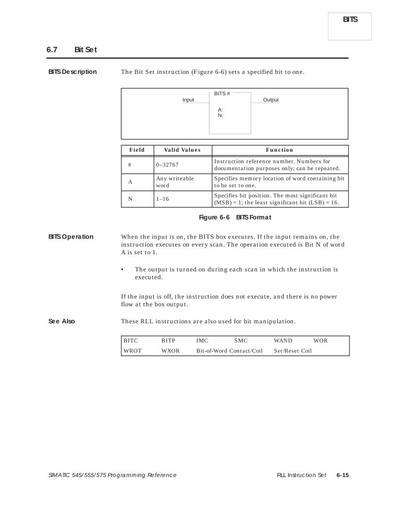
RLL Instruction Set 6-15SIMATIC 545/555/575 Programming Reference
6.7 Bit Set
The Bit Set instruction (Figure 6-6) sets a specified bit to one.
BITS #
A:N:
Input Output
Field Valid Values Function
# 0–32767 Instruction reference number. Numbers fordocumentation purposes only; can be repeated.
A Any writeableword
Specifies memory location of word containing bitto be set to one.
N 1–16 Specifies bit position. The most significant bit(MSB) = 1; the least significant bit (LSB) = 16.
Figure 6-6 BITS Format
When the input is on, the BITS box executes. If the input remains on, theinstruction executes on every scan. The operation executed is Bit N of wordA is set to 1.
• The output is turned on during each scan in which the instruction isexecuted.
If the input is off, the instruction does not execute, and there is no powerflow at the box output.
These RLL instructions are also used for bit manipulation.
BITC BITP IMC SMC WAND WOR
WROT WXOR Bit-of-Word Contact/Coil Set/Reset Coil
BITS Description
BITS Operation
See Also
BITS

RLL Instruction Set6-16 SIMATIC 545/555/575 Programming Reference
6.8 Convert Binary to BCD
The Convert Binary to BCD instruction (Figure 6-7) converts a binaryrepresentation of an integer to an equivalent Binary Coded Decimal (BCD)value. That is, a 16-bit word representing an integer is converted into a32-bit word in which each group of four bits represents a BCD digit. Valuesup to 32,767 are converted to equivalent BCD values.
CBD #
A :BB :
Input Output
Field Valid Values Function
# 0–32767 Instruction reference number. Numbers fordocumentation purposes only; can be repeated.
A Any readable word Specifies memory location of integer to beconverted.
BB Any writeableword
Specifies memory location of the BCD wordafter conversion. BB contains the mostsignificant 16 bits, and BB + 1 contains the leastsignificant 16 bits.
Figure 6-7 CBD Format
When the input is on, the CBD box executes. If the input remains on, theinstruction executes on every scan. The operation of the CBD is describedbelow and illustrated in Figure 6-8.
• If A contains an integer 0–32767, the value is converted to BCD andstored in BB and BB + 1 as shown below, and the box output is turnedon.
BB (BB+1)
TenThousands Hundreds Tens OnesThousands000
MSB LSB MSB LSB
• If A is not in the range 0–32767, there is no power flow at the boxoutput, and BB and BB + 1 do not change.
If the input is off, the instruction does not execute, and there is no powerflow at the box output.
CBD
CBD Description
CBD Operation

RLL Instruction Set 6-17SIMATIC 545/555/575 Programming Reference
Input OutputCBD 1
A: V199BB: V190
A: V199
0 0 0 0 0 0 01 1 1 0 1 0 0 01
BB: V190
0 0 0 0 0 0 00 0 0 0 0 0 0 00
(BB+1): V191
0 0 0 1 0 1 00 0 0 1 1 0 1 00
0 0 0 0 1 2 3 4
A: V200
0 0 1 1 0 0 00 0 0 1 1 1 0 10
BB: V201
0 0 0 0 0 0 00 0 0 0 0 0 0 10
(BB+1): V202
0 0 1 0 0 1 10 0 1 0 0 0 1 10
0 0 0 1 2 3 4 5
Input OutputCBD 3
A: V200BB: V201
Binary codeddecimal
1234
Integer to be converted: 1,234
Binary codeddecimal12345
integer to be converted: 12,345
Example 1integer value less than 9,999
Example 2integer value greater than 9,999
Figure 6-8 Examples of CBD Operation
NOTE: If you plan to use this instruction in a subroutine (using W-memoryoperands), refer to page 4-10 for the discussion of how parameters arepassed to ensure correct operation of the instruction.
This RLL instruction can also be used for BCD conversions.
CDB
Refer to Section E.12 for an application example of the CBD.
See Also
CBD

RLL Instruction Set6-18 SIMATIC 545/555/575 Programming Reference
6.9 Convert BCD to Binary
The Convert BCD to Binary instruction (Figure 6-9) converts BCD inputs tothe binary representation of the equivalent integer.
CDB #
A :B :N :
Input Output
Field Valid Values Function
# 0–32767 Instruction reference number. Numbers fordocumentation purposes only; can be repeated.
A Any readable word Specifies memory location of BCD word to beconverted.
B Any writeableword
Specifies memory location of the integer afterconversion.
N 1–4 Number of digits to be converted.
Figure 6-9 CDB Format
When the input turns on the CDB box executes. If the input remains on, theinstruction executes on every scan. The operation of the CDB follows andillustrated in Figure 6-10:
• The number of digits (N) of the BCD value located in A, is converted toits equivalent binary integer value and stored in B.
• N may range from 1–4, and the BCD digit count is from right to left.For example, if N = 2 and the BCD number in A = 4321, then 21 isconverted, and the value stored in B is 00010101.
• The output turns on after the instruction executes if the digits of theinput word are valid. Each digit of the BCD value in A must be lessthan or equal to 9. The binary values 1010, 1011, 1100, 1101, 1110, and1111 are invalid.
If the digits of the input word are not valid, the instruction does notexecute, and the output does not turn on.
If the input is off, the instruction does not execute and there is no powerflow at the box output.
CDB
CDB Description
CDB Operation

RLL Instruction Set 6-19SIMATIC 545/555/575 Programming Reference
Input OutputCDB 3
A: WX09B: V111
0 1 0 0 0 1 10 0 0 1 0 0 0 10
0 0 0 0 0 0 00 0 0 0 1 0 1 10
4,321 entered fromthumbwheel WX09
N: 2
A: WX09
4 3 2 1
BCD
B: V111 contain integer 21
Input OutputCDB 2
A: WX11B: V190
0 0 0 0 0 1 0 1 0 0 1
0 0 0 0 00 0 1 1 0 0 10N: 4
4 1 9 3
4,193 entered fromthumbwheel WX11
A: WX11
BCD
B: V190 contain integer 4,193
1 0 1 0 1
010
Example 2
Example 1
Figure 6-10 Examples of CDB Operation
This RLL instruction can also be used for BCD conversions.
CBD
Refer to Section E.13 for an application example of the CDB.
See Also
CDB

RLL Instruction Set6-20 SIMATIC 545/555/575 Programming Reference
6.10 Compare
The Compare instruction (Figure 6-11) compares a signed integer value inmemory location A with a signed integer value in memory location B.
CMP #
A :B :LT :GT :
Input Output
Field Valid Values Function
# 0–32767 Instruction reference number. Numbers fordocumentation purposes only; can be repeated.
AB
Any readable word Memory locations of the values being compared.
LT C, Y, B or blankCoil or relay to be turned on if A < B. If you donot want any contacts turned on, designate thiscoil as C0 or leave it blank.
GT C, Y, B or blankCoil or relay to be turned on if A > B. If you donot want any contacts turned on, designate thiscoil as C0 or leave it blank.
Figure 6-11 CMP Format
If the input is on, the value in A is compared to the value in B with theresults listed below. A and B do not change as a result of this instruction.
• If A < B, LT is turned on, GT is turned off, and there is no power flow atthe box output.
• If A > B, GT is turned on, LT is turned off, and there is no power flow atthe box output.
• If A = B, GT and LT are turned off, and the output is turned on.
If the input is off, the GT and LT coils are turned off and there is no powerflow at the box output.
CMP
CMP Description
CMP Operation

RLL Instruction Set 6-21SIMATIC 545/555/575 Programming Reference
NOTE: The Compare instruction computes power flow based on the equalitytest. To compute power flow for two conditions (e.g., ≥), additional RLL isrequired, or you can use the relational contacts.
These RLL instructions can also be used for math operations.
ABSV ADD DIV MULT SQR SUB
Relational Contact
See Also
CMP

RLL Instruction Set6-22 SIMATIC 545/555/575 Programming Reference
6.11 Coils
The various types of RLL coils that are supported are shown in Figure 6-12.Refer to Section 5.1 for a detailed description of their operation.
Y Coils
Normal NOT-ed
C Coils
Normal NOT-ed
Immediate Y Coils
Normal NOT-ed
Set/Reset Coils Y
Set Coil Reset Coil
Yn Yn
Cn Cn
Set/Reset Coil Bit-of-W ord
Yn Yn
Yn Yn
Vn.b Vn.b
Bit-of-W ord Coils
Normal NOT-ed
Set Reset
Vn.b Vn.b
Set/Reset Coil Immediate
Set Reset
Yn Yn
Set/Reset Coils C
Set Coil Reset Coil
Cn Cn
Figure 6-12 Coil Format
These RLL instructions can also be used for electro-mechanicalreplacement.
Contacts CTR DCAT DRUM EDRUM JMP
MCAT MCR MDRMD MDRMW NOT SHRB
SKP/LBL TMR UDC
Coils
See Also

RLL Instruction Set 6-23SIMATIC 545/555/575 Programming Reference
6.12 Contacts
The various types of RLL contacts that are supported are shown inFigure 6-13. Refer to Section 5.1 for a detailed description of their operation.
Xn Xn
Vn Vm
<
> =
<>
≤ ≥
Vn Vm Vn Vm
Vn Vm
Vn Vm Vn Vm
Yn Yn
Cn Cn
Vn.b Vn.b
X Contacts
Normal NOT-ed
Y Contacts
Normal NOT-ed
C Contacts
Normal NOT-ed
Bit-of-W ord Contacts
Normal NOT-ed
Immediate X Contacts
Normal NOT-ed
Relational Contacts
Xn Xn
Figure 6-13 Contact Format
These RLL instructions can also be used for electro-mechanicalreplacement.
Coils CTR DCAT DRUM EDRUM JMP
MCAT MCR MDRMD MDRMW NOT SHRB
SKP/LBL TMR UDC
See Also
Contacts

RLL Instruction Set6-24 SIMATIC 545/555/575 Programming Reference
6.13 Counter (Up Counter)
The Counter instruction (Figure 6-14) counts recurring events. The counteroutput turns on after the counter counts up to a preset number, making itan “up counter.”
CTR #
P :Count Output
Enable
Field Valid Values Function
#Varies withconfiguredmemory
Instruction reference number. Refer to yourcontroller user manual for the number ofcounters supported. The assigned instructionnumber must conform to the requirements of thetimer/counter memory discussed on page 4-5 inSection 4.2.
P 0–32767Preset value of the maximum value (0–32,767) towhich the counter counts. The counter does notcount events beyond the preset value.
Figure 6-14 CTR Format
When the Enable is on:
• The counter is incremented by one each time the Count inputtransitions from off to on
• The output is turned on when the count reaches the preset value.
When enable is off, the current count is set to zero and the output is turnedoff.
CTR
CTR Description
CTR Operation

RLL Instruction Set 6-25SIMATIC 545/555/575 Programming Reference
The counter’s preset value is stored in TCP# and its current count is storedin TCC#. Current values are retained following loss of power provided thatthe controller battery backup is enabled. Other RLL instructions can beused to read or write to the counter variables. You can also use an operatorinterface to read or write to the counter variables. While you areprogramming the counter, you are given the option of protecting the presetvalues from changes made with an operator interface.
NOTE: If you use an operator interface to change TCP, the new TCP value isnot changed in the original RLL program. If the RLL presets are everdownloaded, the changes made with the operator interface are replaced bythe original values in the RLL program.
These RLL instructions can also be used for electro-mechanicalreplacement.
Coils Contacts DCAT DRUM EDRUM JMP
MCAT MCR MDRMD MDRMW NOT SHRB
SKP/LBL TMR UDC
Using the CounterVariables
See Also
CTR

RLL Instruction Set6-26 SIMATIC 545/555/575 Programming Reference
6.14 Discrete Control Alarm Timer
The Discrete Control Alarm Timer (Figure 6-15) is designed for use with asingle input, double feedback device. The input to the DCAT box is derivedfrom the logic that determines the state of the device. The output of theDCAT box controls the device.
You can use the DCAT to replace the several rungs of logic that are requiredto time the field device’s operation and generate alarms in case of failure.
DCAT #
P :OF :CF :OA :CA :
Input Output
Field Valid Values Function
# Varies withconfigured memory
Instruction reference number. Range dependson memory configured for timers/counters. Theassigned instruction number must conform tothe requirements of the timer/counter memorydiscussed on page 4-5 in Section 4.2.
P 0000.1–3276.7 sec. Time allowed for the device to open or close
OF X, Y, C, BOpen Feedback — input from a field device or acontrol relay that senses when the device beingcontrolled has opened to specified position.
CF X, Y, C, BClose Feedback — input from a field device or acontrol relay that senses when the device beingcontrolled has closed to specified position.
OA Y, C, B
Open Alarm — control relay or output thatturns on if the input to the DCAT is on, and theOpen Feedback input does not turn on beforethe DCAT timer times out.
CA Y, C, B
Close Alarm — control relay or output thatturns on if the input to the DCAT has turned offand the Close Feedback input does not turn onbefore the DCAT timer times out.
Figure 6-15 DCAT Format
DCAT
DCAT Description

RLL Instruction Set 6-27SIMATIC 545/555/575 Programming Reference
The state changes for the DCAT are shown in Table 6-2. The DCAT outputalways equals the state of the input.
Table 6-2 DCAT States
1 = open0 = closeX = do not care
Input Condition IF THEN
ANDFeedback Timer Action Alarm Status
OA CAOF CF
Output
1 0 1 timing 0 0 1
1 0 0 timing 0 0 1
1 1 0 reset 2 0 0 1
1 0 0 timed out 1 1 0 1
0 1 0 timing 0 0 0
0 0 0 timing 0 0 0
0 0 1 reset 2 0 0 0
0 0 0 timed out 0 1 0
X 1 1 X 1 1 3
1 Timed out: timer has timed a full preset value of time without a sensorclosing.
2 Reset: timer is at preset value and is not timing.3 Follows input.
NOTE: The DCAT output and alarms are under the control of the JMP orMCR. Unexpected alarm conditions may occur when the DCAT exists withinthe zone of control of a JMP or MCR.
DCAT StateChanges
DCAT

RLL Instruction Set6-28 SIMATIC 545/555/575 Programming Reference
Discrete Control Alarm Timer (continued)
The DCAT timer times down from the preset value specified in P that isstored in TCP-Memory. The timer current time is stored in TCC-Memory.
When the input to the DCAT transitions from off to on, the time delay is setto the preset value defined by P, both alarm outputs OA and CA turn off,and the DCAT output turns on.
While the input remains on, the timer counts down until the OF input turnson or the timer times out.
If the OF input turns on before the timer times out, the time delay is set tozero and the OA remains off.
If OF does not turn on before the timer times out, OA turns on.
If OF turns on before the timer times down, but then goes off again whilethe input is on, OA turns on. The OA turns off if OF then turns on again.
When the input to the DCAT transitions from on to off, the DCAT outputturns off, the time delay is set to the preset value defined by P, and bothalarm outputs OA and CA turn off.
While the input remains off, the timer counts down until the CF input turnson or the timer times out.
If the CF input turns on before the timer times out, the time delay is set tozero and the CA remains off.
If CF does not turn on before the timer times out, CA turns on.
If CF turns on before the timer times out, but then goes off again while theinput is off, CA turns on. The CA turns off if CF then turns on again.
NOTE: If both OF and CF are on simultaneously, both OA and CA turn on.
DCAT
DCAT Operation
Open (Input On)
Close (Input Off)
RLL Instruction Set 6-29SIMATIC 545/555/575 Programming Reference
The DCAT preset value is stored in TCP# and the time remaining until timeout is stored in TCC#. Other RLL instructions can be used to read or writeto these variables. You can also use an operator interface to read or write tothe DCAT variables. While you are programming the DCAT, you are giventhe option of protecting the preset values from changes made with anoperator interface.
NOTE: If you use an operator interface to change TCP, the new TCP value isnot changed in the original RLL program. If the RLL presets are everdownloaded, the changes made with the operator interface are replaced bythe original values in the RLL program.
These RLL instructions can also be used for electro-mechanicalreplacement.
Coils Contacts CTR DRUM EDRUM JMP
MCAT MCR MDRMD MDRMW NOT SHRB
SKP/LBL TMR UDC
Refer to Section E.15 for an application example of the DCAT.
Using the DCATVariables
See Also
DCAT

RLL Instruction Set6-30 SIMATIC 545/555/575 Programming Reference
6.15 Date Compare
The Date Compare instruction (Figure 6-16) compares the current date ofthe real-time clock with the values contained in the designated memorylocations.
DCMP #
DT :
Input Output
Field Valid Values Function
# 0–32767 Instruction reference number. Numbers fordocumentation purposes only; can be repeated.
DT V, W, (G, VMS,VMM, 575)
Designates the memory locations containingdate to be compared to date in real-time clock.*
V(DT) = Year — BCD 0000–0099.
V(DT+1) = Month — BCD 0001–0012.
V(DT+2) = Day of month — BCD 0001–0031.
V(DT+3) = Day of week — BCD 0001–0007.
Enter the hexadecimal value of 00FF for any ofthe fields (year, month, day, etc.) that you wantto exclude from the compare operation.
* BCD values are entered using the HEX data format.
Figure 6-16 DCMP Format
NOTE: If you plan to use this instruction in a subroutine (using W-memoryoperands), refer to page 4-10 for the discussion of how parameters arepassed to ensure correct operation of the instruction.
DCMP
DCMP Description

RLL Instruction Set 6-31SIMATIC 545/555/575 Programming Reference
When there is power flow to the input of the DCMP instruction, the currentdate in the real-time clock is compared to that contained in the designatedmemory locations. If a match occurs, the instruction’s output is turned on.
When the input is off, the comparison is not executed and there is no powerflow at the box output.
These RLL instructions can also be used for date/time functions.
DSET TCMP TSET
DCMP Operation
See Also
DCMP

RLL Instruction Set6-32 SIMATIC 545/555/575 Programming Reference
6.16 Divide
The Divide instruction (Figure 6-17) divides a 32-bit (long word) signedinteger stored in memory locations AA and AA + 1, by a 16-bit signedinteger in memory location B. The quotient is stored in memory location CC,and the remainder is stored in CC + 1.
DIV #
AA :B :CC :
Input Output
Field Valid Values Function
# 0–32767 Instruction reference number. Numbers fordocumentation purposes only; can be repeated.
AAAny readable word
Memory location for the dividend. This is a longword. AA holds the 16 most significant bits, andAA + 1 holds the 16 least significant bits. Whena variable is used, the dividend can range from–2,147,483,648 to +2,147,483,647.
or constant(–32768 to +32767)
Value of the dividend if a constant is used.
B
Any readable wordMemory location for the divisor (one word).When a variable is used, the divisor can rangefrom –32,768 to +32,767, but cannot be zero.B
or constant(–32768 to +32767)
Value of the divisor if a constant is used.
CC Any writeableword
Memory location for the result. CC holds thequotient (a word); CC+1 holds the remainder (aword). Both quotient and remainder must rangefrom –32,768 to +32,767 to be valid.
Figure 6-17 DIV Format
NOTE: If you plan to use this instruction in a subroutine (using W-memoryoperands), refer to page 4-10 for the discussion of how parameters arepassed to ensure correct operation of the instruction.
DIV
DIV Description

RLL Instruction Set 6-33SIMATIC 545/555/575 Programming Reference
When the input is on, the DIV box is executed. If the input remains on, theoperation executes on every scan. The operation of the DIV, that isillustrated in Figure 6-18, follows:
[CC (quotient), CC + 1 (remainder)] = (AA, AA + 1) ÷ B
If B is non-zero, the division is done and the output turns on.Otherwise, the output turns off, and the contents of CC and CC + 1 donot change.
If the input is off, the instruction does not execute, and there is no powerflow at the box output.
0 0 0 0 1 0 0 0 0 0 0 1
integer =
integer = +5450 0 1 0
V9 =
V10 =
V33 =
V40 =
Bit 1 2 3 4 5 6 7 8 9 10 11 12 13 14 15 16
V41 =
integer =
integer =
0 0 0 0 0 1 0 0 0 1 0 0
0 0 0 0 0 0 0 0 0 0 0 0 1 1
1 1 0 0
0 0
0 0 0 0 0 0 0 0 0 1 0 1
0 1 0 0 0 1 1 0 0 0 0 1 1 1
0 0 1 1
0 0 +3,490,183
+6404
+3
DIV 12
B:
CC:
V9
V33
V40
C10X037
AA:
Figure 6-18 Division Example
These RLL instructions can also be used for math operations.
ABSV ADD CMP MULT SQR SUB
Relational Contact
DIV Operation
See Also
DIV
RLL Instruction Set6-34 SIMATIC 545/555/575 Programming Reference
6.17 Time Driven Drum
The Drum (Figure 6-19) simulates an electro-mechanical stepper switch ordrum. It provides 15 output coils and 16 steps that are operated onmultiples of the time base set up for the drum. Each step controls all 15output coils.
The drum functions as described below.
When the drum begins to run, it starts at the step specified by the DrumStep Preset that is stored in DSP-Memory. The drum current step is storedin DSC-Memory. The counts per step, set in the CNT/STP field, are stored inL-Memory and cannot be changed without re-programming the drum. Thecurrent count (counts remaining for a step) is stored in DCC-Memory.
• The drum is enabled when the Enable/Reset input is on.
• When the Enable/Reset is on and the Start input turns on, the drumbegins to run. The drum begins at the step specified by DSP andremains at this step until DCC counts down to zero.
• When DCC for a step reaches zero, the drum advances to the next step,and the coils are turned on/off according to the drum mask for the newstep. Each 1 in the mask designates that a coil is to be turned on, whileeach 0 designates that a coil is to be turned off.
• The drum output comes on and remains on after the last programmedstep is executed. The last programmed step is the last step with anon-zero CNT/STP value (step 9 in Figure 6-19). The drum remains atthe last step until you reset the drum.
• When the Enable/Reset turns off, the drum output turns off, and thedrum returns to the step specified in DSP.
• If the Start input turns off but Enable/Reset remains on, the drumremains at the current step (DSC), and DCC holds its current count.All coils maintain the condition specified by the drum mask for thisstep.
• When the drum is at the Preset step, the output coils follow the statesspecified by the drum mask for that step, even if the Enable/Resetinput is off. Take care to program the mask with a bit pattern that is asafe (home) state for the Preset step.
DRUM
DRUM Description
DRUM Operation

RLL Instruction Set 6-35SIMATIC 545/555/575 Programming Reference
Start
Enable/
Output
Mask0 or 1
Coils (C or Y)
1 172 50
3 23 4 25 5 100 6 10 7 20 8 10 9 2510 011 012 013 014 015 016 0
Y Y Y Y Y C C C C Y Y Y Y Y Y6 7 8 9 2 2 1 1 1 2 2 2 2 2 3
1 7 4 5 0 5 6 7 8 9 05 1 2
4
Reset
PRESET = 1 to 16SEC/CNT = 0 to 32.767STP CNT/STP(1-16) (0 to 32,767)
0 0 0 0 0 0 0 0 0 0 0 0 0 0 00 0 0 0 0 0 0 1 0 0 1 1 1 0 11 1 0 1 0 0 1 0 0 0 0 1 1 1 11 1 0 0 0 0 0 0 0 0 0 1 1 0 00 0 0 0 0 0 0 1 1 1 0 0 0 0 00 0 0 0 1 1 1 1 1 1 1 1 1 1 10 0 0 0 0 0 0 0 0 0 0 0 0 0 00 0 0 0 0 0 0 0 0 0 0 0 0 0 00 0 0 0 0 0 0 1 0 0 1 1 1 0 11 1 0 1 0 0 1 0 0 0 0 1 1 1 11 1 0 0 0 0 0 0 0 0 0 1 1 0 00 0 0 0 0 0 0 1 1 1 0 0 0 0 00 0 0 0 1 1 1 1 1 1 1 1 1 1 10 0 0 0 0 0 0 0 0 0 0 0 0 0 00 0 0 0 0 0 0 0 0 0 0 0 0 0 00 0 0 0 0 0 0 0 0 0 0 0 0 0 0
DRUM #
Field Valid Values Function
#Varies withconfiguredmemory
Instruction reference number. Refer to controlleruser manual for number supported. Theassigned instruction number must conform tothe requirements of the drum memory discussedon page 4-9 in Section 4.2.
PRESET 1–16 Step to which the drum returns when reset.
SEC/CNT 0–32.767 sec. Time base. Amount of time for one count.
Coils Y, C, B, or blank Coils controlled by drum. C0 represents no coil.
STP 1–16 Step number.
CNT/STP 0–32767 Specifies time that drum remains at step. Actualtime/step equals CNT/STP × SEC/CNT in seconds.
Mask 0–1 Mask controls coils turned on (1) or off (0).
Figure 6-19 DRUM Format
DRUM

RLL Instruction Set6-36 SIMATIC 545/555/575 Programming Reference
Time Driven Drum (continued)
Set the Counts/Step for the time that the drum must remain on a stepaccording to one of the following equations.
CNT�STP �
step timeSEC�CNT
� If SEC/CNT is not 0, ⇒
CNT�STP �
step timescan time
� If SEC/CNT is 0, ⇒
For example, if Step 2 is to remain on for 5 seconds and you have set theSEC/CNT at 0.20 seconds, then CNT/STP = 25 as shown.
CNT�STP �
5.00.2
CNT�STP � 25
Other RLL instructions can be used to read or write to the DRUM variables.Use care when programming instructions that can alter or read thesevariables. You can also use an operator interface to read or write to theDRUM variables.
During its operation, the DRUM uses the count preset value that was storedin L-Memory when the DRUM was programmed. Therefore, a new value forcount preset that is written by RLL or by an operator interface has no effecton DRUM operation.
It is possible to read/write data to/from drum memory areas for anunprogrammed drum, using these memory locations like V-Memory.However, if you use TISOFT to display values in DSP or DSC memory, anyvalue not in the range of 1–16 is displayed as 16. By contrast, an APTprogram can display values that are greater than 16 for these variables.
NOTE: If you use an operator interface to change drum preset values, thenew values are not changed in the original RLL program. If the RLL presetsare ever downloaded, the changes made with the operator interface arereplaced by the original values in the RLL program.
DRUM
CalculatingCounts/Step
Using DRUMVariables

RLL Instruction Set 6-37SIMATIC 545/555/575 Programming Reference
These RLL instructions can also be used for electro-mechanicalreplacement.
Coils Contacts CTR DCAT EDRUM JMP
MCAT MCR MDRMD MDRMW NOT SHRB
SKP/LBL TMR UDC
Refer to Section E.5 for an application example of the DRUM.
See Also
DRUM

RLL Instruction Set6-38 SIMATIC 545/555/575 Programming Reference
6.18 Date Set
The Date Set instruction (Figure 6-20) sets the date portion of the real-timeclock to the values contained in designated memory locations.
DSET #
DT :
Input Output
Field Valid Values Function
# 1 to number of oneshots.
Instruction reference number. The assignedinstruction number must conform to therequirements of the one-shot memory discussedon page 4-7 in Section 4.2.
DT V, W, (G, VMS,VMM, 575)
Designates the memory locations containingdate to be written into the real-time clock*.
V(DT) = Year — BCD 0000–0099.
V(DT+1) = Month — BCD 0001–0012.
V(DT+2) = Day of month — BCD 0001–0031.
V(DT+3) = Day of week — BCD 0001–0007.
* BCD values are entered using the HEX data format.
Figure 6-20 DSET Format
NOTE: If you plan to use this instruction in a subroutine (using W-memoryoperands), refer to page 4-10 for the discussion of how parameters arepassed to ensure correct operation of the instruction.
DSET
DSET Description

RLL Instruction Set 6-39SIMATIC 545/555/575 Programming Reference
When the input to the DSET instruction transitions from off to on, the dateportion of the real-time clock is set to the values contained within the threeconsecutive memory locations designated by DT, and the output is turnedon.
NOTE: The time of day status words (STW141–144 and STW223–225) donot reflect the date change until the next RLL scan.
When the input is off, the instruction does not execute and there is no powerflow at the box output.
These RLL instructions can also be used for date/time functions.
DCMP TCMP TSET
DSET Operation
See Also
DSET

RLL Instruction Set6-40 SIMATIC 545/555/575 Programming Reference
6.19 Time/Event Driven Drum
The Time/Event Drum instruction (Figure 6-21) simulates anelectro-mechanical stepper switch or drum. The EDRUM can be indexed bya timer only, an event contact only, or a time and event. A jog input enablesyou to allow either time or an event to advance the drum a step. TheEDRUM provides 15 coils and 16 steps that are operated on multiples of thedrum time base. Each step controls all 15 output coils.
PRESET = 1–16
Event Drum #
SEC/CNT = 0 to 32.767
Start
Enable/Reset
Output
Mask0 or 1
Coils (C or Y)
Jog
Y Y Y Y Y C C C C C Y Y Y C Y6 7 8 9 1 1 1 1 5 5 2 2 2 2 3
0 3 4 5 7 8 6 7 8 9 0
1 17 X25 2 50 3 23 4 25 5 100 Y45 6 10 7 20 8 10 X34 9 25 C5010 011 012 013 0 X9514 015 016 0
STP CNT EVENT(1-16) (0-32,767) (X, Y or C)
0 0 0 0 0 0 0 0 0 0 0 0 0 0 00 0 0 0 0 0 0 1 0 0 1 1 1 0 11 1 0 1 0 0 1 0 0 0 0 1 1 1 11 1 0 0 0 0 0 0 0 0 0 1 1 0 00 0 0 0 0 0 0 1 1 1 0 0 0 0 00 0 0 0 1 1 1 1 1 1 1 1 1 1 10 0 0 0 0 0 0 0 0 0 0 0 0 0 00 0 0 0 0 0 0 0 0 0 0 0 0 0 00 0 0 0 0 0 0 1 0 0 1 1 1 0 11 1 0 1 0 0 1 0 0 0 0 1 1 1 11 1 0 0 0 0 0 0 0 0 0 1 1 0 00 0 0 0 0 0 0 1 1 1 0 0 0 0 00 0 0 0 1 1 1 1 1 1 1 1 1 1 10 0 0 0 0 0 0 0 0 0 0 0 0 0 00 0 0 0 0 0 0 0 0 0 0 0 0 0 00 0 0 0 0 0 0 0 0 0 0 0 0 0 0
Field Valid Values Function
#Varies withconfiguredmemory
Instruction reference number. Refer to controlleruser manual for number supported. Theassigned instruction number must conform tothe requirements of drum memory discussed onpage 4-9 in Section 4.2.
PRESET 1–16 Step to which the drum returns when reset.
SEC/CNT 0–32.767 Time base. Amount of time in seconds for onecount.
EVENT X, Y, C, BDiscrete point that starts countdown of a stepand that advances the drum to the next stepwhen count equals zero.
Coils Y, C, B, or blank Coils controlled by drum. C0 represents no coil.
STP 1–16 Step number.
CNT 0–32767 Specifies time that drum remains at step. Actualtime/step equals CNT × SEC/CNT in seconds.
Mask 0–1 Mask controls coils turned on (1) or off (0).
Figure 6-21 EDRUM Format
EDRUM
EDRUM Description

RLL Instruction Set 6-41SIMATIC 545/555/575 Programming Reference
When the drum begins to run, it starts at the step specified by the DrumStep Preset that is stored in DSP-Memory. The drum current step is storedin DSC-Memory. The counts per step, set in the CNT/STP field, is stored inDCP-Memory. The drum current count is stored in DCC-Memory.
• The drum is enabled when the Enable/Reset input is on.
• When the Enable/Reset is on and the Start input turns on, the drumbegins to run. The drum begins at the step specified by DSP andadvances to the next step depending upon operation of the timer and/orevent.
• When the drum advances a step, coils turns on or off according to themask for the new step. Each 1 in the mask designates that a coil is toturn on, while each 0 designates that a coil is to turn off.
• The drum output turns on, and remains on, after the last programmedstep is executed. The last programmed step is the last step having anevent programmed or having a non-zero CNT/STP preset value (step 13in Figure 6-21). The event must be on (if one was programmed for thisstep) and DCC must be zero. If the event turns off after DCC reacheszero, the drum output remains on and the EDRUM remains at the lastprogrammed step until the drum is reset.
• When the Enable/Reset turns off, the drum output turns off, and thedrum returns to the step specified in DSP.
• If the Start input turns off and Enable/Reset remains on, the drumremains at the current step (DSC), and DCC holds its current count.All coils maintain the condition specified by the drum mask.
• When the drum is at the Preset step, the output coils follow the statesspecified by the drum mask for that step, even if the Enable/Resetinput is off. Take care to program the mask with a bit pattern that is asafe (home) state for the Preset step.
• The drum advances to the next step immediately if the Jog inputtransitions from off to on and the Enable/Reset input is also on.
EDRUM Operation
EDRUM

RLL Instruction Set6-42 SIMATIC 545/555/575 Programming Reference
Time/Event Driven Drum (continued)
Set the Counts for the time that the drum must remain on a step accordingto one of the following equations.
CNT �
step timeSEC�CNT
� If SEC/CNT is not 0, ⇒
CNT �
step timescan time
� If SEC/CNT is 0, ⇒
For example, if Step 2 is to remain on for 5 seconds and you have set theSEC/CNT at 0.20 seconds, then CNT/STP = 25 as shown.
CNT �
5.00.2
CNT � 25
For a step having timer operation only, set the CNT preset value (DCP)greater than 0, and do not program a contact or coil in the event field forthis step. The drum remains at this step until the DCC counts down to zero.When DCC reaches zero, the drum advances to the next step.
For a step having event operation only, set the CNT preset value (DCP) forthe step to 0, and program a contact or coil in the event field for this step.The drum remains at this step until the contact or coil specified by the eventturns on. The drum then advances to the next step.
EDRUM
CalculatingCounts/Step
Timer-triggeredAdvance Only
Event-triggeredAdvance Only
RLL Instruction Set 6-43SIMATIC 545/555/575 Programming Reference
For a step having timer and event operation, set the CNT preset value(DCP) for the step greater than 0 and program a contact or coil in the eventfield for this step. The following actions occur.
• The timer counts down during every scan in which the event is on. Ifthe event turns off, the DCC holds its current value. DCC resumescounting down when the event turns on again. Timing is the same asfor a time-triggered advance.
• When DCC reaches zero, the drum advances to the next step.
For a step having timer or external event operation, set the CNT presetvalue (DCP) for the step greater than 0. Do not program a contact or coil inthe event field for this step. Design the RLL program such that an eventexternal to the drum turns on the Jog input. The drum advances to the nextstep based on either the drum timer or the external event.
Other RLL instructions can be used to read or write to the EDRUMvariables. Use care when programming instructions that can alter or readthese variables. You can also use an operator interface to read or write tothe EDRUM variables.
It is possible to read/write data to/from drum memory areas for anunprogrammed drum, using these memory locations like V-Memory.However, if you use TISOFT to display values in DSP or DSC memory, anyvalue not in the range of 1–16 is displayed as 16. By contrast, an APTprogram can display values that are greater than 16 for these variables.
NOTE: If you use an operator interface to change drum preset values, thenew values are not changed in the original RLL program. If the RLL presetsare ever downloaded, the changes made with the operator interface arereplaced by the original values in the RLL program.
These RLL instructions can also be used for electro-mechanicalreplacement.
Coils Contacts CTR DCAT DRUM JMP
MCAT MCR MDRMD MDRMW NOT SHRB
SKP/LBL TMR UDC
Refer to Section E.6 for an application example of the EDRUM.
Timer and Event-Triggered Advance
Timer or ExternalEvent-triggeredAdvance
Using EDRUMVariables
See Also
EDRUM

RLL Instruction Set6-44 SIMATIC 545/555/575 Programming Reference
6.20 Unconditional End
The END instruction (Figure 6-22) unconditionally terminates the scan.
END
Figure 6-22 END Format
Always terminate your program with the END instruction. When acontroller executes an END instruction, the program scan terminates. Noinstructions occurring after an END executes.
• The controller program scan is always terminated by the unconditionalend.
• No other elements can be on the same rung with an END.
If you use an RLL subroutine, place an END instruction between the lastrung of the main RLL program and the first rung of the subroutine.
Do not use an END instruction to separate RLL tasks. The TASKinstruction indicates that a new RLL task is beginning.
This RLL instruction can also be used for terminating the scan.
ENDC
END
END Description
END Operation
See Also

RLL Instruction Set 6-45SIMATIC 545/555/575 Programming Reference
6.21 Conditional End
The ENDC instruction (Figure 6-23) can terminate the program scan underspecific conditions. Since any instructions after an active ENDC instructionare not executed, this instruction can be used to decrease scan time.
Input
C
END
Figure 6-23 ENDC Format
When the ENDC instruction executes, the current program scanterminates. ENDC operates in conjunction with an input and is executedonly when there is power flow at the input. When the input is off, the ENDCinstruction is not executed, and the program scan is not terminated.
When the ENDC instruction is active, ladder logic following the ENDC isnot executed and outputs following the ENDC are frozen. An active ENDCfunctions as an end statement for MCRs and JMPs that precede it, if it is intheir zones of control. Outputs between the MCR or JMP and the ENDCremain under the control of the MCR or JMP.
For an ENDC contained within a SKP zone of control, the ENDC isoverridden if the SKP receives power flow.
This RLL instruction can also be used for terminating the scan.
END
ENDC Description
ENDC Operation
See Also
ENDC

RLL Instruction Set6-46 SIMATIC 545/555/575 Programming Reference
6.22 Go To Subroutine
The GTS instruction (Figure 6-24) enables you to write RLL programspreceded by a subroutine number and call them to be used where needed.The subroutine number is entered after the GTS to designate thesubroutine to be executed.
GTS #
Field Valid Values Function
# 1–255 Subroutine reference number.
Figure 6-24 GTS Format
When there is power flow to the input of the GTS instruction, the RLLprogram calls the subroutine indicated by the GTS number. For example,when GTS44 has power flow to the input, execution of RLL jumps to SBR44.If there is no power flow to the input, the GTS instruction does not execute,and RLL program does not jump to the subroutine.
! WARNINGThe instructions required to define a subroutine, such as END, RTN, SBR, GTS,and PGTS/PGTSZ, must be entered the way that the controller expects, or elsethe controller changes from RUN to PROGRAM mode and freezes outputs intheir current status, which can cause unexpected controller operation.
Unexpected controller operation can result in death or serious injury topersonnel, and/or damage to equipment.
When you do a run-time edit with TISOFT (Rel 4.2 or later), enter all theinstructions required to define a subroutine (END, RTN, SBR, GTS orPGTS/PGTSZ) before setting the controller to RUN mode; also, use the TISOFTsyntax check function to validate a program before placing the controller inRUN mode. When you do a run-time edit using an earlier release of TISOFT , youmust enter the instructions in this order: END, RTN, SBR, GTS or PGTS/PGTSZ.
GTS
GTS Description
GTS Operation

RLL Instruction Set 6-47SIMATIC 545/555/575 Programming Reference
An example of a subroutine call is shown in Figure 6-25.
(Unconditionalreturn)
(Conditionalreturn)
GTS nnnX1
END
SBR nnn
RTN
RTN
SBR nnn
Endsubroutine
Begin nextsubroutine
Beginsubroutine
Figure 6-25 Example Call to Subroutine
These RLL instructions are also used for subroutine operations.
PGTS PGTSZ RTN SBR SFPGM XSUB
See Also
GTS

RLL Instruction Set6-48 SIMATIC 545/555/575 Programming Reference
6.23 Indexed Matrix Compare
The Indexed Matrix Compare instruction, Figure 6-26, compares apredefined 15-bit mask pattern to the status of up to 15 discrete points. Themask to be compared is selected from a field of up to 16 masks by the stepnumber currently located in CUR PTR. If a match is found, the output turnson.
IMC #
STP
CUR PTR:Compare Output
Mask0 or 1
I/O Points
Enable
123456789
10111213141516
X X X Y Y C C C C C C Y Y Y Y6 7 8 9 1 1 2 3 4 5 5 2 2 2 3
0 8 9 7 8 9 0
0 0 0 0 0 0 0 0 0 0 0 0 0 0 00 0 0 0 0 0 0 1 0 0 1 1 1 0 11 1 0 1 0 0 1 0 0 0 0 1 1 1 11 1 0 0 0 0 0 0 0 0 0 1 1 0 00 0 0 0 0 0 0 1 1 1 0 0 0 0 00 0 0 0 1 1 1 1 1 1 1 1 1 1 10 0 0 0 0 0 0 0 0 0 0 0 0 0 00 0 0 0 0 0 0 0 0 0 0 0 0 0 00 0 0 0 0 0 0 1 0 0 1 1 1 0 11 1 0 1 0 0 1 0 0 0 0 1 1 1 11 1 0 0 0 0 0 0 0 0 0 1 1 0 00 0 0 0 0 0 0 1 1 1 0 0 0 0 00 0 0 0 1 1 1 1 1 1 1 1 1 1 10 0 0 0 0 0 0 0 0 0 0 0 0 0 00 0 0 0 0 0 0 0 0 0 0 0 0 0 00 0 0 0 0 0 0 0 0 0 0 0 0 0 0
(1 to 16)
Address inV-Memory
Field Valid Values Function
# 0–32767 Instruction reference number. Numbers fordocumentation purposes only; can be repeated.
CUR PTRV, W, (G, VMS,VMM, 575)
Memory location of the step number of the maskto be compared to the discrete points.
STP 1–16 Specifies step number of the mask.
I/OPoints
X, Y, C, B, or blank The discrete points to be compared to the mask.
Figure 6-26 IMC Format
IMC
IMC Description

RLL Instruction Set 6-49SIMATIC 545/555/575 Programming Reference
The IMC operation is described below.
• If Enable is off, the controller automatically writes 1 to the CUR PTRaddress regardless of the signal state of the Compare input. The outputis turned off.
• If Enable is on and Compare is on, the current status of up to 15 X, Y,or C points is checked against the predefined bit pattern identified bythe step number loaded into CUR PTR. If a match is found, the boxoutput turns on. Otherwise, the box output turns off.
NOTE: If the CUR PTR value is out of range (greater than 16 or less than1), the controller uses the mask for step 16 to compare to the discrete points.
• If Enable is on and Compare is off, the instruction does not execute,and there is no power flow at the box output.
These RLL instructions are also used for bit manipulation.
BITC BITS BITP SMC WAND WOR
WROT WXOR Bit-of-Word Contact/Coil
IMC Operation
See Also
IMC

RLL Instruction Set6-50 SIMATIC 545/555/575 Programming Reference
6.24 Immediate I/O Read/Write
The IORW instruction (Figure 6-27) allows you to do an immediate read orwrite to discrete or word I/O modules on the local base. For inputs, the datatransfer is directly from the I/O module(s) into the image register. Foroutputs, the data transfer is directly from the image register to the I/Omodules. Refer to Section 3.3 for more information about using immediateI/O in a program.
Output
IORW #
A:N=
Input
Field Valid Values Function
# 0–32767 Instruction reference number. Numbers fordocumentation purposes only; can be repeated.
A X, Y, WX, WYDesignates I/O starting address. If a discretepoint (Xn or Yn), then n – 1 must be a multipleof 8.
NUp to number ofpoints supportedby module.
Designates number of points to move. If A is adiscrete point (Xn or Yn) then N must be amultiple of 8. All points must reside within thesame I/O module.
Figure 6-27 IORW Format
When the input is on, the IORW box is executed. If the input remains on,the instruction is executed on every scan.
• The data transfer takes place when the instruction is executed in RLL.
For inputs (Xs and WXs), the status of the specified number of points iscopied from the I/O module to the image register.
For outputs (Ys and WYs), the status of the specified number of pointsis copied from the image register to the I/O module.
IORW
IORW Description
IORW Operation

RLL Instruction Set 6-51SIMATIC 545/555/575 Programming Reference
• Output status follows input status, unless an error occurs.
For inputs: when the module is not present or does not match I/Oconfiguration, the specified input points in the image register arecleared to zero and the output turns off.
For outputs: when the module is not present or does not match I/Oconfiguration, the status of the specified output points in the imageregister is not copied to the I/O module and the output turns off.
If the input is off, the instruction does not execute and there is no powerflow at the box output.
NOTE: When the IORW copies Y values from the image register to amodule, the current state of the Y points in the image register are written tothe module. If you want these Ys to be controlled by an MCR or a JMP, theMCR or JMP must be used to control the coils that write to the Ys. TheIORW operation is not directly affected by MCRs and JMPs.
These RLL instructions are also used for immediate I/O applications.
Immediate Contact/Coil Immediate Set/Reset Coil TASK
See Also
IORW

RLL Instruction Set6-52 SIMATIC 545/555/575 Programming Reference
6.25 Jump
The Jump instruction (Figure 6-28) is used to freeze the values of thediscrete image register points of the controlled outputs in the JMP’s zone ofcontrol. This instruction is often used when duplication of outputs isrequired and the outputs are controlled by different logic.
JMP #
JMP #
Start of JMP
Zone of control
End of JMPE
Field Valid Values Function
# 1–8 Instruction reference number. Numbers can be repeated.
Figure 6-28 JMP Format
The JMP operates as an output update-enable instruction. The JMP musthave power flow, and not be nested within the zone of control of a JMP nothaving power flow, for ladder logic in the JMP zone of control to change thestatus of outputs.
• Discrete outputs between a JMP and its corresponding JMPE do notchange when the JMP loses power flow.
• JMPE marks the end of the zone of control for the JMP having thesame reference number. If you do not use the JMPE, the remainder ofthe program is placed under the control of the JMP. You can make theJMPE conditional by placing a contact on the same rung as the JMPE.
• When an MCR loses power flow, JMP instructions within the MCR’szone of control are overridden. That is, all outputs in the MCR’s zone ofcontrol turn off when the MCR loses power flow, even when the outputsare frozen in an ON state by a JMP. This includes rung outputs withinthe rung, such as those specified within a drum.
Refer to Section 6.55 for information about the action of the JMP inconjunction with the SKP instruction.
JMP
JMP Description
JMP/JMPEOperation

RLL Instruction Set 6-53SIMATIC 545/555/575 Programming Reference
In Figure 6-29, a JMP is located on rung A, and its zone of control isterminated by JMPE (End Jump) on rung D.
• When JMP 5 has power flow, the ladder logic within its zone of control,(rungs B and C), is executed normally.
• When JMP 5 does not have power flow, all RLL instructions in the JMPzone of control still execute normally, but outputs are not changed.
• Discrete outputs and control relays contained within an instruction,such as a drum, for example, are also controlled by the JMP. InFigure 6-29, Y6, Y7, Y8, C1, C2, and C3, as well as Y12 and Y451, arefrozen when the JMP loses power flow.
X037 Y012
JMP 5X001
X777
JMP 5
A
B
C
D
X010
X010
Y451
STP CNT/STPSEC/CNT = .1PRESET = 1
Drum 1Y Y Y C C C6 7 8 1 2 3
0 0 0 0 0 00 0 0 0 0 01 1 0 1 0 01 1 0 0 0 00 0 0 0 0 00 0 0 0 1 1
1 17 2 50 3 23 4 25 5 100 6 10
E
Zone
of
control
Figure 6-29 Example of JMP Zone of Control
These RLL instructions are also used for electro-mechanical replacement.
Coils Contacts CTR DCAT DRUM EDRUM
MCAT MCR MDRMD MDRMW NOT SHRB
SKP/LBL TMR UDC
See Also
JMP

RLL Instruction Set6-54 SIMATIC 545/555/575 Programming Reference
6.26 Load Address
The Load Address instruction (Figure 6-30) copies the logical address of amemory location into a specified memory location (a long word). Use theLDA as a preparatory statement to the MOVE instruction, when theindirect addressing option is needed.
LDA #
A :AI :BB :BI :
Input Output
Field Valid Values Function
# 0–32767 Instruction reference number. Numbers are fordocumentation purposes only; can be repeated.
A Any readable word Specifies the source address. See “ SpecifyingSource” below.
AIBlank, unsignedconstant (0 to 65535)or any readable word
Specifies an index to be applied to the sourceaddress. See “Specifying Index for Source”below.
BB
For direct address:any writeable word
For indirect address:any readable word
Specifies destination. See “SpecifyingDestination” below.
BIBlank, unsignedconstant (0 to 65535)or any readable word
Specifies index to be applied to destinationaddress. See “Specifying Index for Destination ”below.
Figure 6-30 LDA Format
NOTE: If you plan to use this instruction in a subroutine (using W-memoryoperands), refer to page 4-10 for the discussion of how parameters arepassed to ensure correct operation of the instruction.
LDA
LDA Description

RLL Instruction Set 6-55SIMATIC 545/555/575 Programming Reference
When the input is turned on the LDA box executes. If the input remains on,the instruction executes on every scan. The operation of LDA follows and isillustrated in Figure 6-31.
• The address of the memory location specified in A is copied to thedestination specified in BB.
! WARNINGThe address that is copied to the destination is a logical address, not a physicaladdress.
Using this address as a pointer within as external subroutine can causeunpredictable operation by the controller , which could result in death or seriousinjury to personnel, and/or damage to equipment.
Do not use this address as a pointer within an external subroutine.
• The output is turned on and bit 11 of STW01 is turned off after theinstruction executes, unless an error occurs.
When the destination location is not valid, bits 6 and 11 in STW01 turnon, and (if bit 6 of STW01 was off) STW200 is set to a value of 5. Thedestination contents do not change.
When the input is off, the instruction is not executed and there is no powerflow at the box output. In this case bit 11 of STW01 is turned off.
LDA Operation
LDA
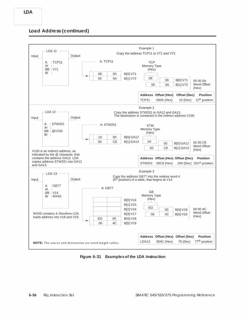
RLL Instruction Set6-56 SIMATIC 545/555/575 Programming Reference
Load Address (continued)
Input Output
A : TCP11AI :BB : V71BI :
LDA 11
Input Output
A : STW201AI :BB : @V100BI :
LDA 12
A: STW201
V100 is an indirect address, asindicated by the @ character, thatcontains the address GA12. LDAcopies address STW201 into GA12and GA13.
1A 00
Example 3
Input OutputCopy the address GB77 into the relative word 4(5th position) of a table, that begins at V14.
A : GB77AI :BB : V14BI : WX55
LDA 13
A: GB77
WX55 contains 4; therefore LDAloads address into V18 and V19.
NOTE: The source and destination are word-length tables.
B[0]:V14
B[1]:V15B[2]:V16B[3]:V17
ED 004C00
B[4]:V18B[5]:V19
ED004C00
B[4]:V18B[5]:V19
GBMemory Type
(Hex)
Example 2
Copy the address STW201 to GA12 and GA13.The destination is contained in the indirect address V100.
B[0]:GA12B[1]:GA1300 C8 1A
00C800
STWMemory Type
(Hex)
B[0]:GA12B[1]:GA13
Example 1
A: TCP11
0E 00
Copy the address TCP11 to V71 and V72.
B[0]:V71B[1]:V7200 0A 0E
000A00
TCPMemory Type
(Hex)
00 00 0AWord Offset(Hex)
B[0]:V71B[1]:V72
00 00 C8Word Offset(Hex)
00 00 4CWord Offset(Hex)
STW201 00C8 (Hex) 200 (Dec) 201st position
Address Offset (Hex) Offset (Dec) Position
TCP11 000A (Hex) 10 (Dec) 11th position
Address Offset (Hex) Offset (Dec) Position
LDA13 004C (Hex) 76 (Dec) 77th position
Address Offset (Hex) Offset (Dec) Position
Figure 6-31 Examples of the LDA Instruction
LDA

RLL Instruction Set 6-57SIMATIC 545/555/575 Programming Reference
You can specify one of the following elements in A.
• Direct address — Specify any readable word, e.g., V100. LDA copies thelogical address for this word into the destination.
• Indirect address — Specify any readable word and designate it anindirect address by preceding the address with the @ character,e.g., @V929. The long word at this indirect address must containanother address, and LDA copies this second logical address into thedestination.
Use the optional field AI as an index into a table when you want to copy anaddress that is in a table. AI designates the relative word, in the tablereferenced by A, the address of which is to be copied. The element at A0 isthe first element in the table. You can specify one of the following in AI.
• Constant index (range 0 to 65535) — You can leave AI blank or enterzero and no indexing is done.
• Variable index — Specify any readable word. The content of this wordis an unsigned integer (0 to 65535) that gives the value of the index.
If an indirect source address is indexed, the controller first resolves theaddress and then indexes it. See Figure 6-32.
K10 is an indirect address, as indicated by the @character, that contains address WX1000.
The actual contents of K10 and K11 are:K10 = 0900 (hex)K11 = 03E7 (hex)
Word 0
Word 1
Word 2
A[0]: WX1000
A[1]: WX1001
A[2]: WX1002
LDA 2
A : @K10AI : 2BB : V37BI :
Input Output
Because index AI = 2, the address that is loadedis WX1002.
The controller resolvesthe indirect address...
... and then loads theaddress determined bythe index.
The address WX1002is loaded into V37.
Figure 6-32 Address/Index Resolution
Specifying Source
Specifying Indexfor Source
LDA

RLL Instruction Set6-58 SIMATIC 545/555/575 Programming Reference
Load Address (continued)
You can specify one of the following elements in BB.
• Direct address — Specify any writeable word, e.g., V631. LDA copiesthe logical address specified by A into the long word at this address.
• Indirect address — Specify any readable word and designate it anindirect address by preceding the address with the @ character, e.g.,@V929. The long word at this indirect address must contain anotheraddress, and LDA copies the address specified by A into the memorylocation specified by this second address. You can enter a readableword, e.g., a K-Memory address, into field BB, but the second addressreferenced by the address in BB must be a writeable word.
Use the optional field BI as an index into a table when you want to copy anaddress into a word in a table. BI designates the relative word in a tablereferenced by BB, into which the source is copied. The element at BB0 is thefirst element in the table.
You can specify one of the following in BI.
• Constant index (range = 0 to 65535) — You can leave BI blank or enterzero, and no indexing is done.
• Variable index — Specify any readable address. The content of thisaddress is an unsigned integer (0 to 65535) that gives the value of theindex.
If an indirect destination address is indexed, the controller first resolves theaddress and then indexes it. See Figure 6-32.
These RLL instructions are also used for word moves.
LDC MIRW MOVE MOVW MWFT MWI
MWIR MWTT SHRW
LDA
SpecifyingDestination
Specifying Indexfor Destination
See Also

RLL Instruction Set 6-59SIMATIC 545/555/575 Programming Reference
6.27 Load Data Constant
The Load Data Constant instruction (Figure 6-33) loads a (positive integer)constant into the designated memory location.
LDC #
A :N=
Input Output
Field Valid Values Function
# 0–32767 Instruction reference number. Numbers fordocumentation purposes only; can be repeated.
A Any writeableword
Memory location where constant is stored.
N 0–32767 Data constant (integer) to be loaded.
Figure 6-33 LDC Format
When the input turns on, the LDC box executes. If the input remains on,the instruction is executed on every scan.
• The data constant designated by N is loaded into the memory locationspecified by A.
• When the function executes, the output turns on.
If the input is off, the instruction does not execute, and there is no powerflow at the box output.
These RLL instructions are also used for word moves.
LDA MIRW MOVE MOVW MWFT MWI
MWIR MWTT SHRW
LDC Description
LDC Operation
See Also
LDC

RLL Instruction Set6-60 SIMATIC 545/555/575 Programming Reference
6.28 Lock Memory
The LOCK instruction (Figure 6-34) works with the UNLCK instruction toprovide a means whereby multiple applications in the 575 systemcoordinate access to shared resources, generally G-Memory data blocks.
LOCK #
Mode
T:
Input Output
AA:
Field Valid Values Function
# 0–32767 Instruction reference number. Numbers fordocumentation purposes only; can be repeated.
Mode Exclusive orShared
An exclusive lock signals other applicationprograms that the resource is unavailable forreading or writing. A shared lock signals otherapplication programs that the resource locationsare available for reading only.
T 0–3276.7 Time in milliseconds for an application programto attempt to acquire control of the lock.
AA G, VMS, VMMMemory location (two words) where lockstructure is stored. Use the same address forassociated UNLCK instruction.
Figure 6-34 LOCK Format
The process by which an application program acquires control of a lock isdescribed below.
• You must initialize the lock data structure prior to its first use.Initialization consists of setting both AA and AA+1 to zero.
LOCK575
LOCK Description
Acquiring Controlof the Lock

RLL Instruction Set 6-61SIMATIC 545/555/575 Programming Reference
NOTE: It is recommended that an application initialize all lock datastructures residing in its application space (G-Memory owned by theapplication) on any scan in which the first scan status word (STW201)indicates a transition from program to run, and on any scan in which thefirst scan status word indicates a power-up restart or complete restart. Ifyou use this method, be sure to follow these programming practices for theindicated first scan conditions:
• Reset all lock-held states associated with the application.
• Do not attempt to acquire any lock in another application’s space.
For this method to operate correctly, all applications sharing a given lockdata structure must be mode-locked, and all restarts involving theseapplications must specify the mode-locked option.
• When the input is on, the application attempts to acquire the lock. Ifthe lock is not available, the application continues to attemptacquisition of the lock (the scan is suspended in the process) until thelock is acquired or the specified timeout (T) has expired. A value of 0 forT results in a single attempt to obtain the lock. A value of 3276.7indicates that the application tries until it obtains the lock or the scanwatchdog fatal error occurs.
If the application obtains the lock before the timeout expires, theoutput turns on and the scan continues.
If the timeout expires before the application obtains the lock, theoutput turns off and the scan continues.
• When an application program attempts to acquire control of the lock,the value in AA (AA+1) is examined. If this value indicates that thelock is free, control of the lock passes to the inquiring applicationprogram, the output turns on, and RLL execution continues at the nextrung.
• When an application program obtains control of the lock, the LOCKinstruction increments the value of a lock/unlock counter. The UNLCKinstruction decrements the lock/unlock counter when an applicationprogram relinquishes control of a lock. If the counter is not equal tozero at the end of the RLL scan, Bit 6 in STW01 is set to 1 and a valueof 3 is written to STW200.
• If the input is off, the instruction does not execute and there is nopower flow at the box output.
LOCK575

RLL Instruction Set6-62 SIMATIC 545/555/575 Programming Reference
Lock Memory (continued)
LOCK does not specify the G-Memory locations that are protected, nor doesLOCK actually prevent an application from reading or writing to theseG-Memory locations. You must determine which G-Memory locationsrequire lock protection and design your program code not to read from orwrite to these locations when control of the lock cannot be acquired. Refer toFigure 6-35 for an example of the LOCK instruction operation.
• When you program an exclusive lock, no other application program canacquire control of the lock. Use this capability in programs that update(write to) the shared resource protected by the lock.
• When you program a shared lock, more than one application programcan acquire control of the lock. Use this capability in programs thatread the shared resource protected by the lock.
C1 C3
C3
Lock data structure is stored in GA2 and GA3. When C1 turns on, LOCK24 attempts to takecontrol of the lock at GA2, GA3. When LOCK24acquires control of the lock, C3 turns on.
All other 575 application programs are designednot to write to GA102 and GA103 when LOCK24 is active.
Exclusive
T: .1AA GA2
LOCK 24
A: V100B: GA102C: GA102
ADD 33
ADD 33 is active only when C3 isturned on by LOCK24.
C3
A: V101B: GA103C: GA103
SUB 63
SUB 63 is active only when C3 isturned on by LOCK24.
C3 C512UNLCK24 relinquishes control of thelock stored in GA2, GA3.
AA GA2
UNLCK 24
C512
C512
Figure 6-35 Example of the LOCK Instruction
This RLL instruction is also used to coordinate access to shared resources.
UNLCK
LOCK575
How the LockProtects Memory
See Also

RLL Instruction Set 6-63SIMATIC 545/555/575 Programming Reference
6.29 Motor Control Alarm Timer
The MCAT instruction (Figure 6-36) is designed for use with a double input,double feedback device. The MCAT operates similarly to the DCATinstruction. However, the MCAT provides additional functions to operatemotor-driven devices that drive in opposite directions. You can use theMCAT to replace several rungs of logic that are required to time the fielddevice’s operation and generate alarms in case of failure.
MCAT #
Output
Open
Close
Stop
P=OF :CF :OA :CA :OO :CO :
Field Valid Values Function
# Varies withconfigured memory
Instruction reference number. Range dependson memory configured for timers/counters. Theassigned instruction number must conform tothe requirements of the timer/counter memorydiscussed on page 4-5 in Section 4.2.
P 0.1–3276.7 Time allowed for device being controlled to openor close.
OF X, Y, C, B Open Feedback — Input from field device thatsenses when device being controlled has opened.
CF X, Y, C, B Close Feedback — Input from field device thatsenses when device being controlled has closed.
OA Y, C, BOpen Alarm — Turns on if Open input to theMCAT is on and Open Feedback (OF) input doesnot turn on before the MCAT timer times out.
CA Y, C, BClose Alarm — Turns on if Close input to theMCAT has turned on and Close Feedback (CF)does not turn on before MCAT timer times out.
OO Y, C, B Open Output — Opens device being controlled.
CO Y, C, B Close Output — Closes device being controlled.
Figure 6-36 MCAT Format
MCAT Description
MCAT

RLL Instruction Set6-64 SIMATIC 545/555/575 Programming Reference
Motor Control Alarm Timer (continued)
The following state changes for the MCAT are evaluated in the order listed.If a condition is true, the specified actions are executed, and all remainingconditions are not tested or executed.
1. If both OF and CF are on thenOO turns off, CO turns off,OA turns on, CA turns on,MCAT output turns off, andTCC is set to zero.
2. If Stop input is on and/or both Open input and Close input are onsimultaneously, thenOO turns off, CO turns off,OA turns off, CA turns off,MCAT output turns on, andMCAT timer is disabled.
3. If open was not been commanded, the timer did not time down, and theOpen input transitions from off to on while the Close input and theStop input are both off, thenOO turns on, CO turns off,OA turns off, CA turns off,MCAT output turns on, andMCAT timer is reset.
4. If open was commanded, the Close and Stop inputs and OF are all off,and the timer did not time down, thenOO turns on, CO turns off,OA turns off, CA turns off,MCAT output turns on, andMCAT timer times down by the amount of the previous scan.
5. If open was commanded, the Close and Stop inputs are off, and OF ison, thenOO turns off, CO turns off,OA turns off, CA turns off,MCAT output turns on, andMCAT timer is marked as timed down. This provides for immediatealarming in case the OF input turns off prior to a subsequent closecommand.
MCAT
MCAT StateChanges

RLL Instruction Set 6-65SIMATIC 545/555/575 Programming Reference
6. If open was commanded, the Close and Stop inputs and OF are all off,and if the timer has timed down, thenOO turns off, CO turns off,OA turns on, CA turns off, andMCAT output is turned off.
7. If close was commanded, the timer did not time down, and the Closeinput transitions from off to on while the Open and Stop inputs areboth off, thenOO turns off, CO turns on,OA turns off, CA turns off,MCAT output turns on, andMCAT timer is reset.
8. If close was commanded, the Open and Stop inputs and CF are all off,and the timer has not timed down, thenOO turns off, CO turns on,OA turns off, CA turns off,MCAT output turns on, andMCAT timer times down by the amount of the previous scan.
9. If close was commanded, if the Open and Stop inputs are off, and CF ison, thenOO turns off, CO turns off,OA turns off, CA turns off,MCAT output turns on, andMCAT timer is marked as timed down. This provides for immediatealarming in case the CF input turns off prior to a subsequent open orstop command.
10. If close has been commanded, if the Open and Stop inputs and CF areall off, and the timer has timed down, thenOO turns off, CO turns off,OA turns off, CA turns on, andMCAT output turns off.
11. If none of the above conditions is true, thenOO turns off, CO turns off,OA turns off, CA turns off, andMCAT output turns on.
MCAT

RLL Instruction Set6-66 SIMATIC 545/555/575 Programming Reference
Motor Control Alarm Timer (continued)
The MCAT timer times down from the preset value specified in P that isstored in TCP-Memory. The time current time is stored in TCC-Memory.
When the Open input transitions from off to on and the Close and Stopinputs are both off, the OO turns on and the timer starts. Once triggered,OO remains on independent of the Open input until one of the followingevents occurs.
• The timer times to 0. The OA turns on, and the OO turns off.
• The OF turns on while the CF remains off.The OO turns off, and the timer resets to 0. If OF turns on and thenturns off, the OA comes on immediately (no time delay) the next timethe box is executed.
• The Stop input turns on. The OO, CO, OA, and CA turn off, and the timer stays where it waswhen Stop was received. If the Stop input turns off while the Openinput is on, then the timer starts at the preset value again—not at thevalue when the Stop input turned on.
• The Close input turns on after the Open input turns off.The CO turns on and the timer starts counting at the preset. The OO isturned off.
When the Close input transitions from off to on, while the Open Commandand Stop Command Inputs are both off, the CO turns on and the timerstarts. CO turns on the motor that closes the valve. Once triggered, the COremains on, independent of the Close input, until one of the following eventsoccurs.
• The timer times to 0.The CA turns on, and the CO turns off.
• The CF turns on while the OF remains off.The CO turns off, and the timer resets. If CF turns on and then turnsoff, the CA comes on immediately (no time delay) the next time the boxexecutes.
• The Stop input turns on.The OO, CO, OA, and CA turn off.
• The Open input turns on after the Close input turns off.The OO turns on. The CO turns off.
MCAT
MCAT Operation
Open InputTurns On
Close InputTurns On

RLL Instruction Set 6-67SIMATIC 545/555/575 Programming Reference
The condition in which both the Close and Open inputs are onsimultaneously is treated as a Stop. The input remaining on when the otherturns off is seen as a transition from off to on, and the MCAT enters theappropriate state.
When the Stop input overlaps an Open or Close input, the Stop overrides aslong as it is on. When the Stop turns off, the remaining input is seen as atransition from off to on and drives the MCAT to the corresponding state.
The condition in which both Feedback signals are on simultaneously is anerror condition. Both Open and Close Alarms turn on, and both Open andClosed Outputs turn off. Removing the conflicting feedback signals does notclear the Open and Close Alarms. One of the MCAT inputs (Open, Close, orStop) must change state in order to clear the error state.
The box output is always on except during an alarm or error condition.
You can use other RLL instructions to read or write to the MCAT variables.You can also use an operator interface to read or write to the MCATvariables. While you are programming the MCAT, you are given the optionof protecting the preset values from changes made with an operatorinterface.
NOTE: If you use an operator interface to change TCP, the new TCP value isnot changed in the original RLL program. If the RLL presets are everdownloaded, the changes made with the operator interface are replaced bythe original values in the RLL program.
These RLL instructions are also used for electro-mechanical replacement.
Contacts Coils CTR DCAT DRUM EDRUM
JMP MCR MDRMD MDRMW NOT SHRB
SKP/LBL TMR UDC
Using the MCATVariables
See Also
MCAT

RLL Instruction Set6-68 SIMATIC 545/555/575 Programming Reference
6.30 Master Control Relay
The Master Control Relay (Figure 6-37) is used to turn off blocks of outputscontrolled by segments of RLL programs. This is done by clearing thediscrete image register points of the controlled outputs to zero.
MCR #
MCR #
Start of MCR
Zone of control
End of MCRE
Field Valid Values Function
# 1–8Instruction reference number. Numbers can berepeated; however, plan logic carefully whennesting MCRs.
Figure 6-37 MCR Format
The MCR operates as an output-enable instruction.
• The MCR must have power flow, and must not be nested within thezone of control of an MCR not having power flow, for discrete outputs inthe MCR zone of control to turn on or stay on.
• The MCR controls the coils and discrete outputs of boxes, e.g., CMP,DCAT, MCAT, drums, etc., in its zone of control.
• MCRE marks the end of the zone of control for the MCR having thesame reference number. If you do not use the MCRE, the remainder ofthe program is placed under the control of the MCR.
You can make the MCRE conditional by placing a contact on the samerung as the MCRE. If you do this, be sure that the contact that controlsthe conditional MCRE is not controlled by the MCR.
MCR
MCR Description
MCR/MCREOperation

RLL Instruction Set 6-69SIMATIC 545/555/575 Programming Reference
! WARNINGUsing MCR to replace a hardwired mechanical master control relay that is usedfor an emergency stop function could jeopardize your control of your process.
Control devices can fail in an unsafe condition that could result in death orserious injury to personnel, and/or damage to equipment.
Never use the MCR to replace a hardwired mechanical master control relayused for an emergency stop function.
Although the MCR controls the coils and discrete outputs of box instructionswithin its zone of control, it does not control the power rail. Therefore, boxinstructions continue to operate normally. In order to disable a box, use anMCR-controlled coil output as a normal contact on the same rung thatcontains the box. See Figure 6-38.
In Figure 6-38 the ADD is controlled by contact C2 when MCR2 is on. WhenMCR2 is off, the ADD does not execute, regardless of the state of C2.
C1 Y12
MCR 2X1
MCR 2
E
ADD #
A :B :C :
C1 C1
C1
C2
Figure 6-38 Example of MCR Control of a Box
Refer to Section 6.25 and Section 6.55 for information about the action ofthe MCR in conjunction with the JMP and SKP instructions.
MCR
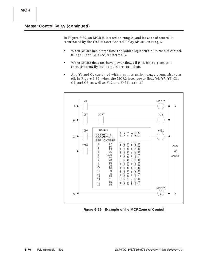
RLL Instruction Set6-70 SIMATIC 545/555/575 Programming Reference
Master Control Relay (continued)
In Figure 6-39, an MCR is located on rung A, and its zone of control isterminated by the End Master Control Relay MCRE on rung D.
• When MCR2 has power flow, the ladder logic within its zone of control,(rungs B and C), executes normally.
• When MCR2 does not have power flow, all RLL instructions stillexecute normally, but outputs are turned off.
• Any Ys and Cs contained within an instruction, e.g., a drum, also turnoff. In Figure 6-39, when the MCR2 loses power flow, Y6, Y7, Y8, C1,C2, and C3, as well as Y12 and Y451, turn off.
X37 Y12
MCR 2X1
X777
MCR 2
A
B
C
D
Zone
of
control
X10
X10
Y451
STP CNT/STPSEC/CNT = .1PRESET = 1
Drum 1Y Y Y C C C6 7 8 1 2 3
0 0 0 0 0 00 0 0 0 0 01 1 0 1 0 01 1 0 0 0 00 0 0 0 0 00 0 0 0 1 10 0 0 0 0 00 0 0 0 0 00 0 0 0 0 01 1 0 1 0 01 1 0 0 0 00 0 0 0 0 00 0 0 0 1 10 0 1 0 0 00 0 1 1 0 00 0 0 1 1 1
1 17 2 50 3 23 4 25 5 100 6 10 7 20 8 10 9 2510 1011 912 513 1514 6115 1016 15
E
Figure 6-39 Example of the MCR Zone of Control
MCR

RLL Instruction Set 6-71SIMATIC 545/555/575 Programming Reference
NOTE: If a SET or a RST coil is within the zone of control of an active MCR(having no power flow), it stops the SET or RST from changing the state ofits associated operand. (That is, SET and RST execution is disabled by theactive MCR.)
These RLL instructions are also used for electro-mechanical replacement.
Coils Contacts CTR DCAT DRUM EDRUM
JMP MCAT MDRMD MDRMW NOT SHRB
SKP/LBL TMR UDC
See Also
MCR

RLL Instruction Set6-72 SIMATIC 545/555/575 Programming Reference
6.31 Maskable Event Drum, Discrete
The MDRMD instruction (Figure 6-40) operates similarly to the event drum.The MDRMD, however, is capable of specifying a configurable mask for eachstep, that allows selection of the coils to be under the control of the fixedmask in each MDRMD step.
PRESET = 1–16
MDRMD #
SEC/CNT = 0 to 32.767
Start
Enable/Reset
Output
Mask
0 or 1
Coils (C or Y)
Jog
Y Y Y Y Y C C C C C Y Y Y C Y6 7 8 9 1 1 1 1 5 5 2 2 2 2 3
0 3 4 5 7 8 6 7 8 9 0
Fixed
0 0 0 0 0 0 0 0 0 0 0 0 0 0 00 0 0 0 0 0 0 1 0 0 1 1 1 0 11 1 0 1 0 0 1 0 0 0 0 1 1 1 11 1 0 0 0 0 0 0 0 0 0 1 1 0 00 0 0 0 0 0 0 1 1 1 0 0 0 0 00 0 0 0 1 1 1 1 1 1 1 1 1 1 10 0 0 0 0 0 0 0 0 0 0 0 0 0 00 0 0 0 0 0 0 0 0 0 0 0 0 0 00 0 0 0 0 0 0 1 0 0 1 1 1 0 11 1 0 1 0 0 1 0 0 0 0 1 1 1 11 1 0 0 0 0 0 0 0 0 0 1 1 0 00 0 0 0 0 0 0 1 1 1 0 0 0 0 00 0 0 0 1 1 1 1 1 1 1 1 1 1 10 0 0 0 0 0 0 0 0 0 0 0 0 0 00 0 0 0 0 0 0 0 0 0 0 0 0 0 00 0 0 0 0 0 0 0 0 0 0 0 0 0 0
1 17 X25 2 50 3 23 4 25 5 100 Y45 6 10 7 20 8 10 X34 9 25 C5010 011 012 013 0 X9514 015 016 0
STP CNT EVENT(1-16) (0-32,767) (X, Y, C, B)
MASK: V-, W-Memory
Field Valid Values Function
#Varies withconfiguredmemory
Instruction reference number. Refer to controlleruser manual for number supported. Theassigned instruction number must conform tothe requirements of the drum memory discussedon page 4-9 in Section 4.2.
MASK V, W, (G, VMS,VMM, 575)
First word of a 16-word table that contains theconfigurable mask output patterns.
PRESET 1–16 Step to which the drum returns when reset.
SEC/CNT 0–32.767 Time base. Amount of time in seconds for onecount.
EVENT X, Y, C, BDiscrete point that starts countdown of a stepand that advances the drum to the next stepwhen count equals zero.
Coils Y, C, B, blank Coils controlled by drum. C0 represents no coil.
STP 1–16 Step number.
CNT 0–32767 Specifies time that drum remains at step. Actualtime/step equals CNT × SEC/CNT in seconds.
Mask 0–1 Mask turns coils on (1) or off (0) according to bitpattern in configurable mask.
Figure 6-40 MDRMD Format
MDRMD
MDRMDDescription

RLL Instruction Set 6-73SIMATIC 545/555/575 Programming Reference
When the drum begins to run, it starts at the step specified by the DrumStep Preset that is stored in DSP-Memory. The current step is stored inDSC-Memory. The counts per step, set in the CNT field, is stored inDCP-Memory. The current count is stored in DCC-Memory.
• The drum is enabled when the Enable/Reset input is on.
• When the Enable/Reset is on and the Start input turns on, the drumbegins to run. The drum begins at the step specified by DSP andadvances to the next step based on operation of the timer and/or event.
• When the drum advances a step, coils turn on/off according to the fixedmask and the current bit pattern in the configurable mask.
• The drum output comes on, and remains on, after the last programmedstep is executed. The last programmed step is the last step having anevent programmed or having a non-zero CNT preset value (step 13 inFigure 6-40). The event must be on (if one was programmed for thisstep) and DCC must be zero. If the event goes off after DCC reacheszero, the drum output remains on and the MDRMD remains at the lastprogrammed step until the drum is reset.
• When the Enable/Reset turns off, the drum output turns off, and thedrum returns to the step specified in DSP.
• If the Start input turns off and Enable/Reset remains on, the drumremains at the current step (DSC), and DCC holds its current count.All coils specified in the configurable mask maintain the conditionspecified by the fixed mask.
• When the drum is at the Preset step, the coils specified in theconfigurable mask follow the states specified by the fixed mask for thatstep, even if the Enable/Reset input is off. Take care to program themask with a bit pattern that is a safe (home) state for the Preset step.
• The drum advances to the next step immediately if the Jog inputtransitions from off to on and the Enable/Reset input is also on.
You can use the MDRMD in applications that require a configurable on/offpattern for the drum coils. To do this, specify all ones (1s) for the fixed maskof every programmed step of the MDRMD and precede the MDRMDinstruction with the necessary instruction(s) to turn off unconditionally allthe MDRMD’s coils. The configurable mask table in memory must thencontain the on/off patterns that are to be written to the coils for each step.
MDRMD Operation
MDRMD

RLL Instruction Set6-74 SIMATIC 545/555/575 Programming Reference
Maskable Event Drum, Discrete (continued)
The configurable mask is specified for each step by a memory location in themask field of the instruction. The configurable mask is located in 16consecutive memory locations (allocated after entry of the first address). Thefirst location corresponds to step 1 of the drum; the second, to step 2, etc.The mask is defined as being configurable because you can change the maskby writing data to the memory locations.
The configurable mask allows selection of the coils to be controlled by thefixed mask. When a bit of the configurable mask is on (set to 1), the fixedmask controls the corresponding coil. When a bit of the configurable mask isoff (set to 0), the corresponding coil is left unchanged by the MDRMD.
The mapping between the configurable mask and the coils is shown below.To match corresponding bits in the mask, coils are numbered from left toright.
Configurablemask wordbit position
Bit 1 of the configurable mask word is unused.
MDRMD coil #
1 2 3 4 5 6 7 8 9 10 11 12 13 14 15 16
1 2 3 4 5 6 7 8 9 10 11 12 13 14 15
Set the Counts/Step for the time that the drum must remain on a stepaccording to one of the following equations. (See also p. 6-42 for anexample.)
CNT �
step timeSEC�CNT
� If SEC/CNT is not 0, ⇒
CNT �
step timescan time
� If SEC/CNT is 0, ⇒
For a step having timer operation only, set the CNT preset value (DCP)greater than 0, and do not program a contact or coil in the event field forthis step. The drum remains at this step until the DCC counts down to zero.When DCC reaches zero, the drum advances to the next step.
For a step having event operation only, set the CNT preset value (DCP) forthe step equal to 0, and program a contact or coil in the event field for thisstep. The drum remains at this step until the contact or coil specified by theevent turns on. Then the drum then advances to the next step.
MDRMD
Defining the Mask
CalculatingCounts/Step
Timer-triggeredAdvance Only
Event-triggeredAdvance Only

RLL Instruction Set 6-75SIMATIC 545/555/575 Programming Reference
For a step having timer and event operation, set the CNT preset value(DCP) for the step greater than 0 and program a contact or coil in the eventfield for this step. The following actions occur.
• The timer counts down during every scan in which the event is on. Ifthe event turns off, the DCC holds its current value. DCC resumescounting down when the event turns on again. Timing is the same asfor a time-triggered advance.
• When DCC reaches zero, the drum advances to the next step.
For a step having timer or external event operation, set the CNT presetvalue (DCP) for the step greater than 0. Do not program a contact or coil inthe event field for this step. Design the RLL program such that an eventexternal to the drum turns on the Jog input. The drum advances to the nextstep based on either the drum timer or the external event.
Other RLL instructions can be used to read or write to the MDRMDvariables. Use care when programming instructions that can alter or readthese variables. You can also use an operator interface to read or write tothe MDRMD variables.
It is possible to read/write data to/from drum memory areas for anunprogrammed drum, using these memory locations like V-Memory.However, if you use TISOFT to display values in DSP or DSC memory, anyvalue not in the range of 1–16 is displayed as 16. By contrast, an APTprogram can display values that are greater than 16 for these variables.
NOTE: If you use an operator interface to change drum preset values, thenew values are not changed in the original RLL program. If the RLL presetsare ever downloaded, the changes made with the operator interface arereplaced by the original values in the RLL program.
These RLL instructions are also used for electro-mechanical replacement.
Coils Contacts CTR DCAT DRUM EDRUM
JMP MCAT MCR MDRMW NOT SHRB
SKP/LBL TMR UDC
Timer and Event-Triggered Advance
Timer or ExternalEvent-TriggeredAdvance
Using MDRMDVariables
See Also
MDRMD

RLL Instruction Set6-76 SIMATIC 545/555/575 Programming Reference
6.32 Maskable Event Drum, Word
The MDRMW instruction (Figure 6-41) operates similarly to the eventdrum, but the MDRMW writes data to a word instead of to individual coils.The MDRMW also is capable of specifying a configurable mask for eachstep. This allows the selection of the bits in the word to be changed by thefixed mask in each MDRMW step.
MDRMW
MDRMWDescription

RLL Instruction Set 6-77SIMATIC 545/555/575 Programming Reference
1 17 X25 2 50 3 23 4 25 5 100 Y45 6 10 7 20 8 10 X34 9 25 C5010 011 012 013 0 X9514 015 016 0
PRESET = 1–16
MDRMW #
SEC/CNT = 0 to 32.767
Start
Enable/Reset
Output
Mask
0 or 1
Jog
+ – – – – – – – – – BIT NO. – – – – – – – – +1 1 1 1 1 1 1
2 3 4 5 6 7 8 9 0 1 2 3 4 5 6
Fixed
OUTPUT: V, WY
STP CNT EVENT(1-16) (0-32,767) (X, Y, C, B)
0 0 0 0 0 0 0 0 0 0 0 0 0 0 00 0 0 0 0 0 0 1 0 0 1 1 1 0 11 1 0 1 0 0 1 0 0 0 0 1 1 1 11 1 0 0 0 0 0 0 0 0 0 1 1 0 00 0 0 0 0 0 0 1 1 1 0 0 0 0 00 0 0 0 1 1 1 1 1 1 1 1 1 1 10 0 0 0 0 0 0 0 0 0 0 0 0 0 00 0 0 0 0 0 0 0 0 0 0 0 0 0 00 0 0 0 0 0 0 1 0 0 1 1 1 0 11 1 0 1 0 0 1 0 0 0 0 1 1 1 11 1 0 0 0 0 0 0 0 0 0 1 1 0 00 0 0 0 0 0 0 1 1 1 0 0 0 0 00 0 0 0 1 1 1 1 1 1 1 1 1 1 10 0 0 0 0 0 0 0 0 0 0 0 0 0 00 0 0 0 0 0 0 0 0 0 0 0 0 0 00 0 0 0 0 0 0 0 0 0 0 0 0 0 0
word output
MASK: V-, W-Memory
Field Valid Values Function
#Varies withconfiguredmemory
Instruction reference number. Refer to controlleruser manual for number supported. Theassigned instruction number must conform tothe requirements of the drum memory discussedon page 4-9 in Section 4.2.
MASK V, W, (G, VMS,VMM, 575)
First word of a 16-word table that contains theconfigurable mask output patterns.
PRESET 1–16 Step to which the drum returns when reset.
SEC/CNT 0–32.767 Time base. Amount of time in seconds for onecount.
EVENT X, Y, C, BDiscrete point that starts countdown of a stepand that advances the drum to the next stepwhen count equals zero.
OUTPUT
WY, V, TCP,TCC,G,W,VMS,VMM,DSP,DSC,DCP,DCC
Word location to which the drum writes. Bit 1 isalways set to zero.
STP 1–16 Step number.
CNT 0–32767 Specifies time that drum remains at step. Actualtime/step equals CNT × SEC/CNT in seconds.
Mask 0–1 Mask gives the value of the bits of the outputword.
Figure 6-41 MDRMW Format
MDRMW

RLL Instruction Set6-78 SIMATIC 545/555/575 Programming Reference
Maskable Event Drum, Word (continued)
When the drum begins to run, it starts at the step specified by the DrumStep Preset that is stored in DSP-Memory. The current step is stored inDSC-Memory. The counts per step, set in the CNT field, are stored inDCP-Memory. The current count is stored in DCC-Memory.
• The drum is enabled when the Enable/Reset input is on.
• When the Enable/Reset is on and the Start input turns on, the drumbegins to run. The drum begins at the step specified by DSP andadvances to the next step based on operation of the timer and/or event.
• When the drum advances a step, individual bits of the output wordturn on/off based on the fixed mask and the current bit pattern in theconfigurable mask.
• The drum output comes on, and remains on, after the last programmedstep has been executed. The last programmed step is the last stephaving an event programmed or having a non-zero CNT preset value(step 13 in Figure 6-41). The event must be on (if one was programmedfor this step) and DCC must be zero. If the event goes off after DCCreaches zero, the drum output remains on and the MDRMW remains atthe last programmed step until the drum is reset.
• When the Enable/Reset turns off, the drum output turn off, and thedrum returns to the step specified in DSP.
• If the Start input turns off and Enable/Reset remains on, the drumremains at the current step (DSC), and DCC holds its current count.All bits specified in the configurable mask maintain the conditionspecified by the fixed mask.
• When the drum is at the Preset step, the bits specified in theconfigurable mask follow the states specified by the fixed mask for thatstep, even if the Enable/Reset input is off. Take care to program themask with a bit pattern that is a safe (home) state for the Preset step.
• The drum advances to the next step immediately if the Jog inputtransitions from off to on and the Enable/Reset input is also on.
MDRMW
MDRMW Operation
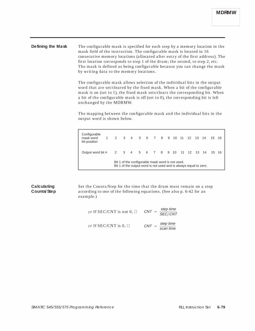
RLL Instruction Set 6-79SIMATIC 545/555/575 Programming Reference
The configurable mask is specified for each step by a memory location in themask field of the instruction. The configurable mask is located in 16consecutive memory locations (allocated after entry of the first address). Thefirst location corresponds to step 1 of the drum; the second, to step 2, etc.The mask is defined as being configurable because you can change the maskby writing data to the memory locations.
The configurable mask allows selection of the individual bits in the outputword that are set/cleared by the fixed mask. When a bit of the configurablemask is on (set to 1), the fixed mask sets/clears the corresponding bit. Whena bit of the configurable mask is off (set to 0), the corresponding bit is leftunchanged by the MDRMW.
The mapping between the configurable mask and the individual bits in theoutput word is shown below.
Configurablemask wordbit position
Bit 1 of the configurable mask word is not used. Bit 1 of the output word is not used and is always equal to zero.
Output word bit #
1 2 3 4 5 6 7 8 9 10 11 12 13 14 15 16
2 3 4 5 6 7 8 9 10 11 12 13 14 15 16
Set the Counts/Step for the time that the drum must remain on a stepaccording to one of the following equations. (See also p. 6-42 for anexample.)
CNT �
step timeSEC�CNT
� If SEC/CNT is not 0, ⇒
CNT �
step timescan time
� If SEC/CNT is 0, ⇒
Defining the Mask
CalculatingCounts/Step
MDRMW

RLL Instruction Set6-80 SIMATIC 545/555/575 Programming Reference
Maskable Event Drum, Word (continued)
For a step having timer operation only, set the CNT preset value (DCP)greater than 0, and do not program a contact or coil in the event field forthis step. The drum remains at this step until the DCC counts down to zero.When DCC reaches zero, the drum advances to the next step.
For a step having event operation only, set the CNT preset value (DCP) forthe step equal to 0, and program a contact or coil in the event field for thisstep. The drum remains at this step until the contact or coil specified by theevent turns on. The drum then advances to the next step.
For a step having timer and event operation, set the CNT preset value(DCP) for the step greater than 0 and program a contact or coil in the eventfield for this step. The following actions occur.
• The timer counts down during every scan in which the event is on. Ifthe event turns off, the DCC holds its current value. DCC resumescounting down when the event turns on again. Timing is the same asfor a time-triggered advance.
• When DCC reaches zero, the drum advances to the next step.
For a step having timer or external event operation, set the CNT presetvalue (DCP) for the step greater than 0. Do not program a contact or coil inthe event field for this step. Design the RLL program so that an eventexternal to the drum turns on the Jog input. The drum advances to the nextstep based on either the drum timer or the external event.
MDRMW
Timer-triggeredAdvance Only
Event-triggeredAdvance Only
Timer and Event-Triggered Advance
Timer or ExternalEvent-triggeredAdvance

RLL Instruction Set 6-81SIMATIC 545/555/575 Programming Reference
Other RLL instructions can be used to read or write to the MDRMWvariables. Use care programming instructions that can alter or read thesevariables. You can also use an operator interface to read from or write to theMDRMW variables.
It is possible to read/write data from/to drum memory areas for anunprogrammed drum, using these memory locations like V-Memory.However, if you use TISOFT to display values in DSP or DSC memory, anyvalue not in the range of 1–16 is displayed as 16. By contrast, an APTprogram can display values that are greater than 16 for these variables.
NOTE: If you use an operator interface to change drum preset values, thenew values are not changed in the original RLL program. If the RLL presetsare ever downloaded, the changes made with the operator interface arereplaced by the original values in the RLL program.
These RLL instructions are also used for electro-mechanical replacement.
Coils Contacts CTR DCAT DRUM EDRUM
JMP MCAT MCR MDRMD NOT SHRB
SKP/LBL TMR UDC
Using MDRMDVariables
See Also
MDRMW
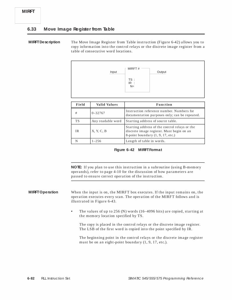
RLL Instruction Set6-82 SIMATIC 545/555/575 Programming Reference
6.33 Move Image Register from Table
The Move Image Register from Table instruction (Figure 6-42) allows you tocopy information into the control relays or the discrete image register from atable of consecutive word locations.
MIRFT #
TS :IR :N=
Input Output
Field Valid Values Function
# 0–32767 Instruction reference number. Numbers fordocumentation purposes only; can be repeated.
TS Any readable word Starting address of source table.
IR X, Y, C, BStarting address of the control relays or thediscrete image register. Must begin on an8-point boundary (1, 9, 17, etc.)
N 1–256 Length of table in words.
Figure 6-42 MIRFT Format
NOTE: If you plan to use this instruction in a subroutine (using B-memoryoperands), refer to page 4-10 for the discussion of how parameters arepassed to ensure correct operation of the instruction.
When the input is on, the MIRFT box executes. If the input remains on, theoperation executes every scan. The operation of the MIRFT follows and isillustrated in Figure 6-43.
• The values of up to 256 (N) words (16–4096 bits) are copied, starting atthe memory location specified by TS.
The copy is placed in the control relays or the discrete image register.The LSB of the first word is copied into the point specified by IR.
The beginning point in the control relays or the discrete image registermust be on an eight-point boundary (1, 9, 17, etc.).
MIRFT
MIRFT Description
MIRFT Operation

RLL Instruction Set 6-83SIMATIC 545/555/575 Programming Reference
• All words are copied into the control relays or the image register oneach scan.
• The output turns on when the instruction executes.
If the input is off, the instruction does not execute, and there is no powerflow at the box output.
Control relays
0 1 0 1 0 1 0V100V101V102V103
Table
MSB LSB0 10 10 111 0
MIRFT 2OutputInput
0 1 0 1 0 1 0
C14
C15
C13
C11
C12
C10
C9
C21
C22
C20
C18
C19
C17
C16
C23
C24
1 0 1 0 1 0 101
0 0 0 1 1 1 1
C30
C31
C29
C27
C28
C26
C25
C37
C38
C36
C34
C35
C33
C32
C39
C40
0 0 1 1 1 1 000
0 0 0 1 1 1 11 01 10 100 0
TS : V100IR : C9N = 2
Figure 6-43 Example of MIRFT Operation
These RLL instructions are also used for table operations.
MIRTT STFE STFN TAND TCPL TOR
TTOW TXOR WTOT WTTA WTTO WTTXO
See Also
MIRFT

RLL Instruction Set6-84 SIMATIC 545/555/575 Programming Reference
6.34 Move Image Register to Table
The Move Image Register to Table instruction (Figure 6-44) allows you tocopy information from the control relays or the discrete image register to atable of consecutive word locations.
MIRTT #
IR :TD :N=
Input Output
Field Valid Values Function
# 0–32767 Instruction reference number. Numbers fordocumentation purposes only; can be repeated.
IR X, Y, C, BStarting address of the control relays or thediscrete image register. Must begin on an8-point boundary (1, 9, 17, etc.)
TD Any writeableword
Starting address of the destination table.
N 1–256 Length of table in words.
Figure 6-44 MIRTT Format
NOTE: If you plan to use this instruction in a subroutine (using B-memoryoperands), refer to page 4-10 for the discussion of how parameters arepassed to ensure correct operation of the instruction.
When the input is on, the MIRTT box executes. If the input remains on, theoperation executes on every scan. The operation of the MIRTT follows and isillustrated in Figure 6-45.
• The On/Off state of up to 4096 bits (256 words × 16 bits) is copied fromthe control relays or the discrete image register, starting at the bitaddress specified by IR.
The starting point must be on an 8-point boundary (1, 9, 17, etc.). Bitsare copied in groups of 16.
The copy begins with the lowest numbered bit address and is placedinto word locations, beginning with the LSB of the word specified byTD.
MIRTT
MIRTT Description
MIRTT Operation

RLL Instruction Set 6-85SIMATIC 545/555/575 Programming Reference
• All bits are copied into the word locations each scan. There must be asufficient number of discrete points to copy all bits into the table of Nwords.
• The output turns on when the instruction executes.
If the input is off, the instruction does not execute and there is no powerflow at the box output.
Control relays
1 1 1 0 0 0 0V100V101V102V103
Table
MSB LSB0 10 01 011 1
IR : C9TD : V100N = 2
MIRTT 2
OutputInput
1 1 1 0 0 0 0
C14
C15
C13
C11
C12
C10
C9
C21
C22
C20
C18
C19
C17
C16
C23
C24
1 1 0 0 0 0 111
1 0 1 0 1 0 1
C30
C31
C29
C27
C28
C26
C25
C37
C38
C36
C34
C35
C33
C32
C39
C40
0 1 0 1 0 1 010
1 0 1 0 1 0 11 01 01 000 1
Figure 6-45 Example of MIRTT Operation
These RLL instructions are also used for table operations.
MIRFT STFE STFN TAND TCPL TOR
TTOW TXOR WTOT WTTA WTTO WTTXO
See Also
MIRTT

RLL Instruction Set6-86 SIMATIC 545/555/575 Programming Reference
6.35 Move Image Register to Word
The Move Image Register to Word instruction (Figure 6-46) copies aspecified number of bits from the discrete image register or the control relaymemory locations to a designated word memory location. Up to 16 bits arecopied in a single scan.
MIRW #
IR :A :N=
Input Output
Field Valid Values Function
# 0–32767 Instruction reference number. Numbers fordocumentation purposes only; can be repeated.
IR X, Y, C, B Starting address of the control relays or thediscrete image register bits to be copied.
A Any writeableword
Specifies word memory location to which bitsare copied.
N 1–16 Number of bits to be copied.
Figure 6-46 MIRW Format
NOTE: If you plan to use this instruction in a subroutine (using B-memoryoperands), refer to page 4-10 for the discussion of how parameters arepassed to ensure correct operation of the instruction.
When the input is on, the MIRW box executes. If the input remains on, theoperation executes on every scan. The operation of the MIRW box followsand is illustrated in Figure 6-47.
• Up to 16 bits (N) are copied, beginning with the lowest numberedaddress, that is specified by IR.
• The bits are moved into the word memory location specified by A,beginning with the LSB of the word. If fewer than 16 bits are moved,the remaining bits are set to 0. All bits are copied during a single scan.
• The output turns on when the instruction executes.
If the input is off, the instruction does not execute, and there is no powerflow at the box output.
MIRW
MIRW Description
MIRW Operation

RLL Instruction Set 6-87SIMATIC 545/555/575 Programming Reference
X1
X2
X3
X4
X5
X6
X7
X8
X9
X10
X11
X12
X13
X14
X15
X16
16151413121110987654321
Specified wordMSB LSB
X, Y, C,or B
Figure 6-47 Example of MIRW Operation
These RLL instructions are also used for word moves.
LDA LDC MOVE MOVW MWFT MWI
MWIR MWTT SHRW
Refer to Section E.7 for an application example of the MIRW.
See Also
MIRW

RLL Instruction Set6-88 SIMATIC 545/555/575 Programming Reference
6.36 Move Element
The Move Element instruction (Figure 6-48) copies data elements (bytes,words, or long words) from a source location to a destination location.
MOVE #
TS :SI :TD :DI :N=
Input OutputType
Field Valid Values Function
# 0–32767 Instruction reference number. Numbers fordocumentation purposes only; can be repeated.
Type Byte, Word, orLong Word
Specifies type of the element(s) to be copied:byte = 8 bits, word = 16 bits, long word = 32 bits.
TS
Signed constant(range varies withsize of element) orAny readable word
Specifies source element to be copied. Can be aconstant, a direct address, or an indirectaddress (a memory location containing theaddress of another memory location).
SI
Blank,Unsigned constant(0 to 65535) orAny readable word
Optional index. Designates that the SIth
element in a table referenced by TS is to becopied. The element at TS is zero (0).
TD
For direct address:Any writeableword For indirectaddress: Anyreadable word
Specifies the destination of the copy. TD can bea direct address or an indirect address (a longword containing the address of another memorylocation).
DI
Blank,Unsigned constant(0 to 65535) orAny readable word
Optional index. Designates the relative elementin a table referenced by TD, into which theelement is copied. The element at TD is zero (0).
NUnsigned constant(1 to 32767) orAny readable word
Specifies number of elements to be copied.
Figure 6-48 MOVE Format
NOTE: If you plan to use this instruction in a subroutine (using W-memoryoperands), refer to page 4-10 for the discussion of how parameters arepassed to ensure correct operation of the instruction.
MOVE
MOVE Description

RLL Instruction Set 6-89SIMATIC 545/555/575 Programming Reference
When the input is on, the MOVE box executes. If the input remains on, theinstruction executes on every scan. The operation of MOVE is describedbelow and illustrated in Figure 6-49.
• The element(s) specified in A are copied to the destination specifiedin B.
• The output turns on and STW01 bit 11 turns off after the instructionexecutes, unless an error occurs. See notes below.
NOTE: If the count is invalid or any referenced data element is undefined,the user program error bit (6) and the instruction failed bit (11) in STW01are set to 1. If this is the first program error encountered on the currentRLL scan, the value 5 (Table overflow) is written to STW200. Finally, powerflow is turned off and the RLL scan continues with the next instruction ofthe current network. The contents of the destination are not changed.
NOTE: For the 575, if a MOVE instruction attempts to access a non-existentVMEbus address, a VMEbus error occurs. If this is the first VMEbus error,the offending address is written to STW227-STW228 and STW229-STW230is cleared. Next, the user program error bit (6) and the instruction failed bit(11) in STW01 are set to 1 and, if this is the first program errorencountered on the current RLL scan, the value 7 (VMEbus error) is writtento STW200. The controller then continues execution with the next RLLinstruction of the current network after turning power flow off. If theVMEbus error occurred in the middle of the MOVE operation, a partialmove occurred.
When the input is off, the instruction does not execute and there is no powerflow at the box output. Bit 11 of STW01 turns off.
MOVE Operation
MOVE

RLL Instruction Set6-90 SIMATIC 545/555/575 Programming Reference
Move Element (continued)
Input Output
1 1 1 1 1 1 11 1 1 1 1 1 1 01
Example 1
B: V71 Contains –2
MOVE 34
TS Contains: –2Copy the value –2 tolocation V71.
Example 2Input Output
TD[3]: V114
MOVE 35
TD[2]: V113
TD[1]: V112
TD[0]: V111
Copy the constant value9137 into a table thatbegins at V111. The copystarts at relative word 3 ofthe table. Values arecopied into the 4th, 5th,6th, 7th and 8th positionsof the table.
Word 0
Word 1
Word 2
Word 3
TD[4]: V115Word 4
TS: Contains 9137
TD[5]: V116Word 5
0 0 1 0 0 1 10 1 0 1 1 0 0 10
0 0 1 0 0 1 10 1 0 1 1 0 0 10
0 0 1 0 0 1 10 1 0 1 1 0 0 10
0 0 1 0 0 1 10 1 0 1 1 0 0 10
ÅÅÅÅÅÅÅÅÅÅÅÅÅÅÅÅÅÅÅÅÅÅÅÅÅÅÅ
0 0 1 0 0 1 10 1 0 1 1 0 0 10
TD[6]: V117Word 6
TS : –2SI :TD : V71DI :N = 1
Word
TS : 9137SI :TD : V111DI : 3N = 5
Word
ÅÅÅÅÅÅÅÅÅÅÅÅÅÅÅÅÅÅ
TD[7]: V118Word 7
TS[3]: V114
Example 3Input OutputMOVE 36
ÅÅÅÅÅÅÅÅÅÅÅÅÅÅÅÅ
ÅÅÅÅÅÅÅÅÅÅÅÅÅÅÅÅ TS[2]: V113
TS[1]: V112
ÅÅÅÅÅÅÅÅÅÅÅÅÅÅÅÅ
TS[0]: V111
TD[1]: V700
TD[0]: V699
TD[2]: V701
Table 1
Table 2
Word 0
Word 1
Word 2
Word 3
ÅÅÅÅÅÅÅÅÅÅÅÅÅÅÅÅÅÅÅÅÅÅÅÅ Word 0
Word 1
Word 2
TS[4]: V115Word 4
TD[3]: V702Word 3
TS : V111SI : 3TD : V699DI : 2N = 2
Word Copy the 4th and 5th
words (relative words 3and 4) of a table thatbegins at V111.
Place the copy in asecond table that starts atV699, beginning atrelative word 2. Valuesare copied into the 3rd
and 4th positions of thetable.
Figure 6-49 Examples of the MOVE Instruction
MOVE

RLL Instruction Set 6-91SIMATIC 545/555/575 Programming Reference
Example 4Input OutputMOVE 37
TS[6], TS[7]: V114
TS[4], TS[5]: V113
TS[2], TS[3]: V112
TS[0], TS[1]: V111
1 byte
ÅÅÅÅÅÅÅÅÅÅÅÅÅÅÅÅ
ÅÅÅÅÅÅÅÅÅÅÅÅÅÅÅÅ
Table 1
Word 0
Word 1
Word 2
Word 3
ÅÅÅÅÅÅÅÅÅÅÅÅÅÅÅÅ TD[2], TD[3]: V700
TD[0], TD[1]: V699
TD[4], TD[5]: V701
Table 2
Word 0
Word 1
Word 2
1 byte
Byte 0 Byte 1
Byte 2 Byte 3
Byte 4 Byte 5
Byte 6
Byte 0 Byte 1
Byte 2 Byte 3
Byte 4
MSB LSB
Byte 5
Copy the 6th and 7th bytes(relative bytes 5 and 6) ofa table that begins atV111.
Place the copy in asecond table that starts atV699, beginning atrelative byte 4. Values arecopied into the 5th and 6th
positions of the table.
TS : V111SI : 5TD : V699DI : 4N = 2
Byte
Example 5Input OutputMOVE 38
TS[0]: V100V101
Table 1
Long Word 0
Long Word 1
Long Word 2
Long Word 3
Long Word 4
V500 contains 2;therefore the TS indexpoints to V104.
V501 contains 3;therefore TD indexpoints to V26.
Table 2
Long Word 0
Long Word 1
Long Word 2
Long Word 3
Long Word 4
Long Word 5
TS : V100SI : V500TD : V20DI : V501N = 3
Long Word
Copy the 3rd, 4th and 5th
long words (relative words2–4) of a table that beginsat V100.
Place the copy in asecond table that starts atV20, beginning at relativeword 3. Values are copiedinto the 4th, 5th, 6th
positions of the table.
TS[1]: V102V103
TS[2]: V104V105
TS[3]: V106V107
TS[4]: V108V109
TD[0]: V20V21
TD[1]: V22V23
TD[2]: V24V25
TD[3]: V26V27
TD[4]: V28V29
TD[5]: V30V31
Figure 6-49 Examples of the MOVE Instruction (continued)
MOVE

RLL Instruction Set6-92 SIMATIC 545/555/575 Programming Reference
Move Element (continued)
Example 6
Input OutputMOVE 39Table 1
Long Word 0
Long Word 1
Long Word 2
Long Word 3
Long Word 4
V100 is an indirect address, asindicated by the @ character,that contains address WX1000.
K30 contains 5; therefore5 long words are copied.
Table 2
Long Word 0
Long Word 1
Long Word 2
Long Word 3
Long Word 4
V102 contains 3; thereforethe TS index points toWX1006.
V103 is an indirect address,as indicated by the @character, that containsaddress WY100.
Long Word 5
Long Word 6
Long Word 7
TS : @V100SI : V102TD : @V103DI :N = K30
Long WordCopy the 4th–8th longwords (relative words 3–7)of a table that begins atWX1000.
Place the copy in a secondtable that starts at WY100,beginning at relative longword 0. Values are copiedinto the 1st–5th positions ofthe table.
TS[0]: WX1000WX1001
TS[1]: WX1002WX1003
TS[2]: WX1004WX1005
TS[3]: WX1006WX1007
TS[4]: WX1008WX1009
TS[5]: WX1010WX1011
TS[6]: WX1012WX1013
TS[7]: WX1014WX1015
TD[0]: WY100WY101
TD[1]: WY102WY103
TD[2]: WY104WY105
TD[3]: WY106WY107
TD[4]: WY108WY109
The actual contents ofV100 and V101 are:V100 = 0900 (Hex)V101 = 03E7 (Hex)
The actual contents ofV103 and V104 are:V103 = 0A00 (Hex)V104 = 0064 (Hex)
Figure 6-49 Examples of the MOVE Instruction (continued)
MOVE

RLL Instruction Set 6-93SIMATIC 545/555/575 Programming Reference
Designate the type of the data elements to be moved.
• Byte — The element is 8 bits long.
• Word — The element is 16 bits long.
• Long word — The element is 32 bits long.
You can specify any of the following elements in TS.
• Constant value (range is determined by the data element type) —Specify any signed integer. When the MOVE executes, the specifiedvalue is copied to each element of the destination table.
• Direct address — Specify any readable word and designate it a directaddress. MOVE copies the contents of the memory location(s), startingat this address, to the destination.
• Indirect address — Specify any readable word and designate it anindirect address by preceding the address with the “@” character,e.g., @V929. The long word at this indirect address must containanother address, and MOVE copies the contents of the memorylocation(s), starting at this second address, to the destination.
Use the LDA instruction to load an address into a memory location.
Use the first optional field SI as an index into a table when you want to copyelements of a table to a destination. SI designates the relative element, inthe table referenced by TS, that is to be copied. The element at TS0 is thefirst element in the table. You can specify one of the following in SI.
• Constant index (range = 0 to 65535) — You can leave IN blank or enter0 and no indexing is done.
• Variable index — Specify any readable word. The content of this wordis an unsigned integer (0–65535) that gives the element number of thefirst element to copy.
If an indirect source address is indexed, the controller first resolves theaddress and then indexes it. See Figure 6-50.
Specifying Type ofElements
Specifying Source
Specifying Indexfor Source
MOVE

RLL Instruction Set6-94 SIMATIC 545/555/575 Programming Reference
Move Element (continued)
MOVE 3
TS : @K10SI : 2TD : V37DI :N = 1
Input OutputWord K10 is an indirect address, as indicated by the @ character,that contains address WX1000.
The actual contents of K10 and K11 are:K10 = 0900 (Hex)K11 = 03E7 (Hex)
Word 0
Word 1
Word 2
TS[0]: WX1000
TS[1]: WX1001
TS[2]: WX1002
Because index SI = 2, the contents of WX1002 are moved.
The controller resolves the indirectaddress . . .
. . . and then moves the contents atthe address determined by the index.
The contents ofWX1002 aremoved into V37.
Figure 6-50 Address/Source Index Resolution
You can specify one of the following elements in TD.
• Direct address — Specify any writeable word and designate it a directaddress. MOVE copies the source element(s) into the memorylocation(s) starting at this address.
• Indirect address — Specify any readable word and designate it anindirect address by preceding the address with the @ character,e.g., @V929. The long word at this indirect address must containanother address, and MOVE copies the source element(s) into thememory location(s), starting at this second address. Use the LDAinstruction to load an address into a memory location. You can enter areadable word, e.g., a K-Memory address into field TD, but the secondaddress referenced by the address in TD must be a writeable word.
Use the second optional field DI as an index into a table when you want tocopy an element(s) into a table. DI designates the relative element in atable, referenced by TD, into which the source is copied. The element at TD0is the first element in the table.
You can specify one of the following in DI.
• Constant index (range = 0 to 65535) — You can leave DI blank or enter0 and no indexing is done.
• Variable index — Specify any readable word. The content of thisaddress is an unsigned integer (0 to 65535) that gives the elementnumber of the first element in the table to which the source element(s)is copied.
If an indirect destination address is indexed, the controller first resolves theaddress and then indexes it. See Figure 6-51.
MOVE
SpecifyingDestination
Specifying Indexfor Destination

RLL Instruction Set 6-95SIMATIC 545/555/575 Programming Reference
MOVE 3
TS : V37SI : TD : @K10DI : 2N = 1
Input OutputWord K10 is an indirect address, as indicated by the @ character,that contains address WY1000.
The actual contents of K10 and K11 are:K10 = 0A00 (Hex)K11 = 03E7 (Hex)
Word 0
Word 1
Word 2
TD[0]: WY1000
TD[1]: WY1001
TD[2]: WY1002
Because index DI = 2,the contents of V37 aremoved into WY1002.
The controller resolves the indirectaddress . . .
. . . and then moves the value intothe address determined by the index.
Figure 6-51 Address/Destination Index Resolution
Designate the number of elements to be copied in the count field N. You canspecify one of the following in N.
• Constant count: Specify an unsigned integer in the range 1–32767.
• Variable count: Enter any readable word. The value of the count isdetermined by the contents of this word when the MOVE executes. Thecount range is 0–32767, where 0 means that no elements move.
These RLL instructions are also used for word moves.
LDA LDC MIRW MOVW MWFT MWI
MWIR MWTT SHRW
Specifying Numberof Elements toMove
See Also
MOVE

RLL Instruction Set6-96 SIMATIC 545/555/575 Programming Reference
6.37 Move Word
The Move Word instruction (Figure 6-52) copies up to 256 contiguous wordsfrom one location to another. The starting memory location for the words tobe moved is specified by A, and the starting memory location for theirdestination is specified by B. All words are copied in a single scan.
MOVW #
A :B :N =
Input Output
Field Valid Values Function
# 0–32767 Instruction reference number. Numbers fordocumentation purposes only; can be repeated.
AAny readable wordor constant
Starting memory location for the words to becopied.A or constant
(–32768 to +32767) Value to be copied if a constant is used.
B Any writeableword
Starting memory location for the destination.
C 1–256 Number of words to be copied.
Figure 6-52 MOVW Format
NOTE: If you plan to use this instruction in a subroutine (using W-memoryoperands), refer to page 4-10 for the discussion of how parameters arepassed to ensure correct operation of the instruction.
MOVW
MOVW Description

RLL Instruction Set 6-97SIMATIC 545/555/575 Programming Reference
When the input is on, the MOVW box executes. If the input remains on, theoperation executes on every scan. The operation of MOVW follows and isillustrated in Figure 6-53.
• A table of up to 256 (N) words, with a starting memory locationspecified by A, is copied.
If a constant value is specified in A, then the constant is copied to alldestination locations.
• The words are copied to a destination beginning at the memory locationdesignated by B.
• The output turns on when the instruction executes.
If the input is off, the instruction does not execute, and there is no powerflow at the box output.
Input OutputMOVW 1
0 0 0 1 0 0 00 0 1 1 0 0 0 10
1 1 1 1 0 0 00 0 1 1 0 0 0 10
0 0 0 1 0 0 10 1 1 1 1 1 1 11
1 1 1 1 1 1 11 1 1 1 0 0 0 10
A: TCP45
TCP46
TCP47
TCP48
0 0 0 1 0 0 00 0 1 1 0 0 0 10
1 1 1 1 0 0 00 0 1 1 0 0 0 10
0 0 0 1 0 0 10 1 1 1 1 1 1 11
1 1 1 1 1 1 11 1 1 1 0 0 0 10
V301
V302
V303
TCP45
B: V300
V300
A : TCP45B : V300N = 4
Figure 6-53 The MOVW Operation
These RLL instructions are also used for word moves.
LDA LDC MIRW MOVE MWFT MWI
MWIR MWTT SHRW
MOVW Operation
See Also
MOVW

RLL Instruction Set6-98 SIMATIC 545/555/575 Programming Reference
6.38 Multiply
The Multiply instruction (Figure 6-54) multiplies a signed integer inmemory location A by a signed integer in memory location B. The product isstored in one long word, CC and CC + 1.
MULT #
A :B :
CC :
Input Output
Field Valid Values Function
# 0–32767 Instruction reference number. Numbers fordocumentation purposes only; can be repeated.
A Any readable word Memory location for the multiplicand (a word).
BAny readable wordor constant
Memory location for the multiplier (a word).B or constant
(–32768 to +32767) Value of the multiplier if a constant is used.
CC Any writeablelong word
Memory location for the product (a long word).CC holds the 16 most significant bits, andCC + 1 holds the 16 least significant bits.
Figure 6-54 MULT Format
NOTE: If you plan to use this instruction in a subroutine (using W-memoryoperands), refer to page 4-10 for the discussion of how parameters arepassed to ensure correct operation of the instruction.
When the input is on, the MULT box executes. If the input remains on, theoperation executes on every scan. The operation of the MULT that isillustrated in Figure 6-55 is (CC, CC + 1) = A × B.
• The values in A and B are not affected by the operation.
• When the multiplication executes, the output turns on.
If the input is off, the instruction does not execute, and there is no powerflow at the box output.
MULT
MULT Description
MULT Operation

RLL Instruction Set 6-99SIMATIC 545/555/575 Programming Reference
MULT 1
A:
B:
CC:
0 0 0 0 0 0 0 0 0 1 0 1
0 1 0 0 0 1 1 0 0 0 0 1 0 0
0 0 0 1 1 0 0 1 0 0 0 0 0 1 0 0
0 0 0 0 1 0 0 0 1 0 0 0 0 1
integer = +6404
integer = +545
integer = +3,490,180
0 0
0 0 1 1
0 0
WX9 =
V307 =
V308 =
V309 =
Bit 1 2 3 4 5 6 7 8 9 10 11 12 13 14 15 16
V308
V307
WX9
C10X37
Figure 6-55 Multiplication Example
These RLL instructions can also be used for math operations.
ABSV ADD CMP DIV SQRT SUB
Relational Contact
See Also
MULT

RLL Instruction Set6-100 SIMATIC 545/555/575 Programming Reference
6.39 Move Word from Table
The Move Word from Table instruction (Figure 6-56) copies a word from atable to a V-Memory location. A table pointer designates the address of thenext word in the table to be copied. One word is copied each scan.
MWFT #
A :B :
S :N=
Input Output
Enable/Reset
Field Valid Values Function
# Varies withcontroller model
Instruction reference number. Refer tocontroller user manual for number supported.The assigned instruction number must conformto the requirements of table-move memory onpage 4-6 discussed in Section 4.2.
A V, W, (G, VMS,VMM, 575)
Specifies memory location of the table pointer.The value contained in pointer A is the memorylocation in the table of the next word to becopied.
B V, W, (G, VMS,VMM, 575)
Memory location of the destination.
S V Starting address of the table.
N 1–256 Number of words to be copied.
Figure 6-56 MWFT Format
NOTE: If you plan to use this instruction in a subroutine (using W-memoryoperands), refer to page 4-10 for the discussion of how parameters arepassed to ensure correct operation of the instruction.
The operation of the MWFT is described below and illustrated inFigure 6-57.
• When the Enable/Reset is off, the table starting address S loads intopointer A.
• When the Enable/Reset turns on, the box is enabled. When the Inputalso turns on, the following actions occur.
A word is copied from the table address specified by the valuecontained in pointer A to the memory location specified by B.
MWFT
MWFT Description
MWFT Operation

RLL Instruction Set 6-101SIMATIC 545/555/575 Programming Reference
After the word is copied, table pointer A, that holds the address of thenext word in the table to be copied, increments by 1.
If the Input and the Enable/Reset remain on, one word is copied everyscan. As each word is copied, the table pointer increments until Nwords are copied.
• The output turns on when the last word is copied.
• When the instruction is reset, all table values remain unchanged, anddestination address B contains the last word copied from the table.
If the Enable/Reset is off, the instruction does not execute, and there is nopower flow at the box output.
V200
V229
Input OutputMWFT 2
A: V500
N=30
B: V100S: V200
1st word copied from table
30th word copied from table
V201
V202
V228
V227
Enable/Reset
V100 Pointer A
= 200
= 201
= 202
= 227
= 228
= 229
V500
200
Table starting addressS = V200
Destinationaddress B
Word copiedfrom table
When the MWFT is reset, data in location Sis loaded into pointer A so that V500 equals200. This “200” tells the MWFT to copy thenext word from V200.
When the Enable/Reset turns on and theInput turns on, the word in V200 is placed inV100. V500 (the pointer) is incremented byone so that it points to V201 (V500 equals201). As long as the Enable/Reset and theInput are on, operation continues until 29more words have been copied.
When a word has been copied from V229,the MWFT output turns on. V500 remains at229, and the box does not execute againuntil it is reset.
Figure 6-57 The MWFT Operation
These RLL instructions are also used for word moves.
LDA LDC MIRW MOVE MOVW MWI
MWIR MWTT SHRW
Refer to Section E.10 for an application example of the MWFT.
See Also
MWFT

RLL Instruction Set6-102 SIMATIC 545/555/575 Programming Reference
6.40 Move Word with Index
The Move Word with Index instruction (Figure 6-58) allows you to copy upto 256 words from one area of V-Memory to another area of V-Memoryduring a single scan.
MWI #
A :B :
N :
Input Output
Field Valid Values Function
# 0–32767 Instruction reference number. Numbers fordocumentation purposes only; can be repeated.
A
V, W, (G, VMS,VMM, 575)or constant(–32768 to +32767)
Memory location of word which gives theV-Memory index for the base of the source table.The addressed word can contain a value in therange 1 to 32767, corresponding to V1 throughV32767, respectively.
B V, W, (G, VMS,VMM, 575)
Memory location of word which gives theV-Memory index for the base of the source table.The addressed word can contain a value in therange 1 to 32767, corresponding to V1 throughV32767, respectively.
N V, W, (G, VMS,VMM, 575)
Memory location of word which gives thenumber of words to be moved. The addressedword can contain a value in the range 0 (Don’tMove) through 256.
Figure 6-58 MWI Format
NOTE: If you plan to use this instruction in a subroutine (using W-memoryoperands), refer to page 4-10 for the discussion of how parameters arepassed to ensure correct operation of the instruction.
When the input is on, the MWI box executes. If the input remains on, theoperation is executed on every scan. The operation of the MWI is describedbelow and illustrated in Figure 6-59.
• The V-Memory table having a starting index specified in the wordaddressed by A is copied to the V-Memory table having a starting indexspecified in the word addressed by B.
MWI
MWI Description
MWI Operation

RLL Instruction Set 6-103SIMATIC 545/555/575 Programming Reference
• Up to 256 words can be copied as determined by the content of the wordaddressed by N.
• All words are copied into the destination table each scan.
• If the sum of the number of words to move and either the source(destination) table index exceeds the configured size (in words) ofV-Memory, or if the number of words exceeds 256, the instruction doesnot execute. The output turns on when the instruction is executed.
• If either the source or the destination pointer plus table length exceedsV-Memory size, the instruction does not execute. The output is turnedoff, and bit 11 in STW01 is set.
If the input is off, the instruction does not execute, and there is no powerflow at the box output.
Input OutputMWI 31
A: V500B: V100N: V200
0 0 0 1 0 0 00 0 1 1 0 0 0 10
1 1 1 1 0 0 00 0 1 1 0 0 0 10
0 0 0 1 0 0 10 1 1 1 1 1 1 11
1 1 1 1 1 1 11 1 1 1 0 0 0 10
A: V500 = 190
V191
V192
V193
0 0 0 1 0 0 00 0 1 1 0 0 0 10
1 1 1 1 0 0 00 0 1 1 0 0 0 10
0 0 0 1 0 0 10 1 1 1 1 1 1 11
1 1 1 1 1 1 11 1 1 1 0 0 0 10
V1001
V1002
V1003
V190
B: V100 = 1000
V1000
N: V200 = 4
Figure 6-59 The MWI Operation
These RLL instructions are also used for word moves.
LDA LDC MIRW MOVE MOVW MWFT
MWIR MWTT SHRW
See Also
MWI

RLL Instruction Set6-104 SIMATIC 545/555/575 Programming Reference
6.41 Move Word to Image Register
The Move Word to Image Register instruction (Figure 6-60) copies aspecified number of bits from a word memory location to the discrete imageregister or into the control relay memory locations. All bits are copied in asingle scan.
MWIR #
A :IR :N=
Input Output
Field Valid Values Function
# 0–32767 Instruction reference number. Numbers fordocumentation purposes only; can be repeated.
A Any readable word Specifies memory location from which the bitsare copied.
IR Y, C, B Starting address of the control relays or thediscrete image register.
N 1–16 Number of bits to be copied.
Figure 6-60 MWIR Format
NOTE: If you plan to use this instruction in a subroutine (using B-memoryoperands), refer to page 4-10 for the discussion of how parameters arepassed to ensure correct operation of the instruction.
When the input is on, the MWIR box executes. If the input remains on, theoperation executes on every scan. The operation of the MWIR box isdescribed below and illustrated in Figure 6-61.
• Up to 16 bits (N) in the word memory location specified by A are copied,beginning with the least significant bit of the word.
• Bits are copied into the discrete image register or into the control relaymemory locations, starting at the address designated by IR. The bitsare copied during a single scan.
• The output turns on when the instruction is executed.
If the input is off, the instruction does not execute, and there is no powerflow at the box output.
MWIR
MWIR Description
MWIR Operation

RLL Instruction Set 6-105SIMATIC 545/555/575 Programming Reference
Y16
Y15
Y14
Y13
Y12
Y11
Y10
Y9
Y8
Y7
Y6
Y5
Y4
Y3
Y2
Y1
1 2 3 4 5 6 7 8 9 10 11 12 13 14 15 16
Specified wordMSB LSB
Y, C, or B
Figure 6-61 The MWIR Format
These RLL instructions are also used for word moves.
LDA LDC MIRW MOVE MOVW MWFT
MWI MWTT SHRW
Refer to Section E.8 for an application example of the MWIR.
See Also
MWIR

RLL Instruction Set6-106 SIMATIC 545/555/575 Programming Reference
6.42 Move Word To Table
The Move Word To Table instruction (Figure 6-62) copies a word from asource in memory to a destination within a table. A pointer designates thememory location in the table into which the next word is copied. One word iscopied per scan.
MWTT #
A :B :S :N=
OutputInput
Enable/Reset
Field Valid Values Function
# Varies withcontroller model
Instruction reference number. Refer tocontroller user manual for number supported.The assigned instruction number must conformto the requirements of table-move memorydiscussed on page 4-6 in Section 4.2.
A V, W, (G, VMS,VMM, 575)
Specifies memory location of the word to becopied.
B V, W, (G, VMS,VMM, 575)
Specifies memory location of the table pointer.The value contained in pointer B is the tablememory location into which the next word iscopied.
S V Starting address of the table.
N 1–256 Size of the table in words.
Figure 6-62 MWTT Format
NOTE: If you plan to use this instruction in a subroutine (using W-memoryoperands), refer to page 4-10 for the discussion of how parameters arepassed to ensure correct operation of the instruction.
The operation of the MWTT is described below and shown in Figure 6-63.
• When the Enable/Reset is off, the table starting address S is loaded intopointer B.
• When the Enable/Reset turns on, the box is enabled. When the Inputalso turns on, the following actions occur.
MWTT
MWTT Description
MWTT Operation

RLL Instruction Set 6-107SIMATIC 545/555/575 Programming Reference
A word is copied from the memory location specified by A to the tablememory location specified by the value contained in pointer B.
Pointer B, which holds the destination memory location in the table forthe next word, increments by 1.
If the Input remains on, one word is copied every scan. As each word iscopied, the table pointer increments until N words are copied.
• The output turns on when the last word is copied.
• When the instruction is reset, all values in the table remainunchanged.
If the Enable/Reset is off, the instruction does not execute, and there is nopower flow at the box output.
V200
V229
Input OutputMWTT 1
A: V100
N: 30
B: V500S: V200
1st word copied into table
30th word copied into table
V201
V202
V228
V227
Enable/Reset
V100 Pointer B
= 200
= 201
= 202
= 227
= 228
= 229
V500
200
Table starting addressS = V200
Source address A
Word to copyinto table
When the MWTT is reset, data in location Sis loaded into pointer B so that V500 equals200. This “200” tells the MWTT to copy thenext word into V200.
When the Enable/Reset turns on and theInput turns on, the word in V100 is placed inV200. V500 (the pointer) is incremented byone so that it points to V201 (V500 equals201). As long as the Enable/Reset and theInput are on, operation continues until 29more words have been copied.
When a word has been copied into V229,the MWTT output turns on. V500 remains at229, and the box does not execute againuntil it is reset.
Figure 6-63 The MWTT Operation
These RLL instructions are also used for word moves.
LDA LDC MIRW MOVE MOVW MWFT
MWI MWIR SHRW
Refer to Section E.9 for an application example of the MWTT.
See Also
MWTT

RLL Instruction Set6-108 SIMATIC 545/555/575 Programming Reference
6.43 NOT
The NOT instruction (Figure 6-64) inverts the power flow.
:NOT:Input Output
Figure 6-64 NOT Format
The NOT changes the power flow to the state opposite its current state.Refer to Figure 6-65 for an example of how the NOT can simplifyprogramming.
NOTE: Do not program a NOT in parallel with any rung that does notconnect to the power rail.
C10X38 X39X37
: NOT :
C10X37
X38
X97
The NOT enables you to replace this structure . . . . . . with this one.
Figure 6-65 NOT Example
These RLL instructions are also used for electromechanical replacement.
Coils Contacts CTR DCAT DRUM EDRUM
JMP MCAT MCR MDRMD MDRMW SHRB
SKP/LBL TMR UDC
NOT
NOT Description
NOT Operation
See Also

RLL Instruction Set 6-109SIMATIC 545/555/575 Programming Reference
6.44 One Shot
The One Shot instruction (Figure 6-66) turns on an output for a single scan.
:O:Input Output#
Field Valid Values Function
# Varies with controllermodel
Instruction reference number. Refer tocontroller user manual for number supported.The assigned instruction number must conformto the requirements of One Shot memorydiscussed on page 4-7 in Section 4.2. Each OneShot instruction must have a uniqueinstruction number.
Figure 6-66 One Shot Format
The operation of the One Shot is described below.
• When the input transitions from off to on, the output turns on forexactly one scan.
• After the One Shot executes, its input must be off for at least one scanbefore the instruction executes again.
If the input is off, the instruction does not execute, and there is no powerflow at the output.
Refer to Section E.14 for an application example of the One Shot.
One ShotDescription
One ShotOperation
One Shot

RLL Instruction Set6-110 SIMATIC 545/555/575 Programming Reference
6.45 PID Loop
The PID instruction (Figure 6-67) performs the proportional – integral –derivative (PID) fast loop function.
NOTE: The PID instruction is not supported by TISOFT.
PID #
A:
Input Output
Field Valid Values Function
# 0–65535 Instruction reference number. Numbers fordocumentation purposes only; can be repeated.
A Any readable wordor constant
Specifies word that contains the fast loopnumber (valid fast loop number: 129 to 256).
A Any readable wordor constant PID fast loop number if constant is used (valid
fast loop number: 129 to 256).
Figure 6-67 PID Format
The PID instruction can be used anywhere within the RLL program that asingle-line input box instruction can be used. This instruction allows you toschedule a fast loop for immediate execution.
When power flow is on for the PID instruction, the referenced fast loopexecutes immediately to completion. The result of the fast loop is availableto the next element of the current RLL rung. The fast loop algorithm usesthe floating-point math coprocessor; consequently, it executes faster andwith less overhead than a standard loop.
You can schedule a fast loop to execute every scan or cyclically by placingthe PID instruction in a cyclic task. However, to ensure correct functioningof the fast loop (and SmarTune, if used,) schedule the fast loop to execute ona consistent time basis.
PID
PID Fast LoopDescription
PID Operation

RLL Instruction Set 6-111SIMATIC 545/555/575 Programming Reference
Fast loop programming is done by using the same programming table usedfor loops 1 through 128. Data entered in the SAMPLE RATE field, however,is not used since the sample rate is based on when you schedule the PIDinstruction to execute. Refer to Chapter 9, section 9.4 for information aboutprogramming loops.
NOTE: The ramp/soak feature is not supported by the fast loops.
When the input is turned on, the PID box will execute the loop algorithm fora particular fast loop (129–256) to completion as part of the RLL processand the box output will turn on. If the input remains on, the instructionexecutes on every scan. The following exceptions cause the program’sexecution to fail:
• If the fast loop is not configured, user program error 13 is logged inSTW200 and there is no power flow at the box output.
• If the fast loop is disabled, user program error 14 is logged in STW200and there is no power flow at the box output.
When the input is off, the instruction does not execute, and there is nopower flow at the box output.
Refer to Chapter 9 for information on loop programming.See Also
PID

RLL Instruction Set6-112 SIMATIC 545/555/575 Programming Reference
6.46 Parameterized Go To Subroutine
PGTS (Figure 6-68) operates similarly to the GTS instruction. Use PGTS tocall a section of the RLL program that is preceded by a subroutine numberand execute it. Unlike GTS, the PGTS allows you to pass parameters to asubroutine. These parameters allow you to write a generic subroutine usingparameter identifiers (IN1–IN20) instead of specific memory locations.Several PGTS instructions (using different memory locations asparameters) can then call the same general subroutine.
IN1 :IN2 :IN3 :IN4 :IN5 :IN6 :IN7 :IN8 :IN9 :IN10 :IN11 :IN12 :IN13 :IN14 :IN15 :IN16 :IN17 :IN18 :IN19 :IN20 :
PGTS #Input
Field Valid Values Function
# 1–32 Designates subroutine to call. You can passparameters only to subroutines numbered 1–32.
IN
IN followed by anyreadable bit orword; IO followedby any writeablebit or word.
Designates address that contains data to beread by the subroutine. Change the field toshow IO when you want the subroutine to writedata to the address after it completes execution.When the field shows IN, the subroutine onlyreads data at the address. B and W locations arevalid only when PGTS is used in a subroutine.
Figure 6-68 PGTS Format
NOTE: If subroutine parameters (W or B memory) are used as operands ofinstructions, note that parameter passing by PGTS and PGTSZ if by value.An operand that implies multiple memory locations will access multiple Wor B locations and not multiple locations from their original memory area.Only explicitly passed parameters may be accessed with W or B operands.Refer to page 4-10 for the discussion of how parameters are passed toensure correct operation of the instruction.
PGTS
PGTS Description

RLL Instruction Set 6-113SIMATIC 545/555/575 Programming Reference
PGTS operation is described below and shown in Figure 6-69.
• When the input turns on, the contents of each parameter are set equalto the contents of the memory location specified in the parameter field.Then the subroutine indicated by the PGTS number is called.
• When the subroutine returns control to the main RLL program, thecontents of the memory location specified in each read/write (IO)parameter field is set equal to the contents of the parameter. Thecontents of memory locations designated IN are not changed.
• Contents of parameters are stored in PGTS discrete and wordparameter areas (Section 4.2). When you use a parameter in thesubroutine, refer to discrete points as Bn and words as Wn, wheren = the number of the parameter.
• When you program a PGTS with TISOFT, the parameters must beentered consecutively. That is, do not skip any parameters.
• If you do not need to specify parameters, use the GTS instead (GTSuses less L-Memory).
• While you can still access any memory location from a subroutine, thePGTS allows you to create a generic subroutine that is called bymultiple PGTS instructions, varying the parameters.
If the input is off, the instruction does not execute and the subroutine is notcalled for execution.
! WARNINGWhen you do a run-time edit, you must enter all the instructions required todefine a subroutine before setting the controller to RUN mode. If you enterthese instructions out of order , the controller changes from RUN to PROGRAMmode and freezes the outputs in their current status, which could causeunexpected operation of the controller .
Unexpected controller operation can result in death or serious injury topersonnel, and/or equipment damage.
To ensure that instructions have been entered correctly , use the syntax checkfunction to validate a program before placing the controller in RUN mode.When you do a run-time edit using an earlier release of TISOFT, you must enterthe instructions in this order: END, RTN, SBR, GTS or PGTS/PGTSZ.
PGTS Operation
PGTS
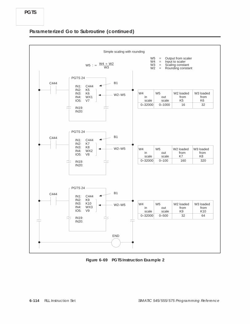
RLL Instruction Set6-114 SIMATIC 545/555/575 Programming Reference
Parameterized Go to Subroutine (continued)
W5 : � W4 � W2W3
W4inscale
C444
END
IN1: C444IN2: K5IN3: K6IN4: WX1IO5: V7
IN19:IN20:
PGTS 24
Simple scaling with rounding
C444IN1: C444IN2: K7IN3: K8IN4: WX2IO5: V8
IN19:IN20:
PGTS 24
0–32000 0–1000 16 32
C444IN1: C444IN2: K9IN3: K10IN4: WX3IO5: V9
IN19:IN20:
PGTS 24
W5 = Output from scalerW4 = Input to scalerW3 = Scaling constantW2 = Rounding constant
W5outscale
W2 loadedfromK5
W3 loadedfromK6
0–32000 0–100 160 320
W4inscale
W5outscale
W2 loadedfromK7
W3 loadedfromK8
0–32000 0–500 32 64
W4inscale
W5outscale
W2 loadedfromK9
W3 loadedfromK10
B1
W2–W5
B1
W2–W5
B1
W2–W5
Figure 6-69 PGTS Instruction Example 2
PGTS

RLL Instruction Set 6-115SIMATIC 545/555/575 Programming Reference
SBR 24
C770
DIV1
A: W6
B: W3
B1 C770
ADD1
A: W4
C: W7
B: W2
B1 C770
RTN
C: W6
MOVW2
A: W6
B: W5
B1
N= 1
Add the constant to provide for proper rounding after thedivision.
Divide by the scaling constant.
Output the scaled value to W5.
C770MOVW1
A: +0
B: W6
B1
N= 1
W6 is the most significant word in the dividend and must becleared to zero for division to be correct.
Figure 6-69 PGTS Instruction Example 2 (continued)
PGTS

RLL Instruction Set6-116 SIMATIC 545/555/575 Programming Reference
Parameterized Go To Subroutine (continued)
NOTE: Avoid a direct reference in a subroutine to a memory location that isalso identified as a parameter in the PGTS instruction. Otherwise, you cancreate a condition where the value of the parameter and the value in thememory location do not agree. Refer to the example in Figure 6-70.
If you use an instruction that copies long words into or from the subroutine,you need to allocate a parameter for each word of each long word that iscopied.
For example, the product of a multiplication is stored as a long word. Twoparameters are required to transfer the product from the subroutine to themain program. If you multiply the contents of V22 by the contents of V23and store the product in V50 and V51, then both V50 and V51 must belisted as consecutive parameters.
These RLL instructions are also used for subroutine operations.
GTS PGTSZ RTN SBR SFPGM SFSUB XSUB
PGTS
See Also

RLL Instruction Set 6-117SIMATIC 545/555/575 Programming Reference
C1
END
SBR 24
RTN
IO: Y1
IN19:IN20:
PGTS 24
C1 C1 Y1
C1
Y1 Y2
C1
C1
B1
Y1 is off.
Although Y1 is now on,Y2 is off. If programintent was to have Y2on whenever Y1 turnson, the program failedbecause of referencingboth B1 and Y1 (thememory location).
B1 is turned on.(Y1 is not affected.)
Since Y1 is off,Y2 is off.
B1 is moved to Y1.(Y1 turns on)
Y1 is moved to B1.(B1 is off.)Control goes toSubroutine 24.
1.
2.
3.
4.
5.
6.
If an IO parameter IO1, that specifies a non-parameter memory location Y1, is passed to a subroutine, andthe subroutine references Y1 directly, then the values for IO1 and Y1 may not agree when the subroutinereturns control back to the main program.
Control returns toRLL program
Figure 6-70 PGTS Instruction Example 1
PGTS

RLL Instruction Set6-118 SIMATIC 545/555/575 Programming Reference
6.47 Parameterized Go To Subroutine (Zero)
The PGTSZ instruction (Figure 6-71) operates similarly to the PGTSinstruction. PGTSZ calls an RLL subroutine for execution and passesparameters to it. Unlike PGTS, the PGTSZ clears all discrete I/Oparameters when the input to the PGTSZ is off.
IN1 :IN2 :IN3 :IN4 :IN5 :IN6 :IN7 :IN8 :IN9 :IN10 :IN11 :IN12 :IN13 :IN14 :IN15 :IN16 :IN17 :IN18 :IN19 :IN20 :
PGTSZ #
Input
Field Valid Values Function
# 1–32 Designates subroutine to call. You can passparameters only to subroutines numbered 1–32.
IN
IN followed by anyreadable bit orword; IO followedby any writeablebit or word.
Designates address that contains data to beread by the subroutine. Change the field toshow IO when you want the subroutine to writedata to the address after it completes execution.When the field shows IN, the subroutine onlyreads data at the address. B and W locationsvalid only when PGTS is used in a subroutine.
Figure 6-71 PGTSZ Format
NOTE: If subroutine parameters (W or B memory) are used as operands ofinstructions, note that parameter passing by PGTS and PGTSZ if by value.An operand that implies multiple memory locations will access multiple Wor B locations and not multiple locations from their original memory area.Only explicitly passed parameters may be accessed with W or B operands.Refer to page 4-10 for the discussion of how parameters are passed toensure correct operation of the instruction.
PGTSZ
PGTSZ Description

RLL Instruction Set 6-119SIMATIC 545/555/575 Programming Reference
When the input turns on, operation is identical to that of the PGTS,described in Section 6.46.
If the input is off, all discrete I/O parameters turn off, and the subroutine isnot called for execution.
! WARNINGWhen you do a run-time edit with TISOFT (Rel 4.2 or later), enter all theinstructions required to define a subroutine (END, RTN, SBR, GTS orPGTS/PGTSZ) before setting the controller to RUN mode. Otherwise, thecontroller changes from RUN to PROGRAM mode and freezes outputs in theircurrent status, which could cause unexpected operation of the controller .
Unexpected controller operation can result in death or serious injury topersonnel, and/or equipment damage.
Use the TISOFT syntax check function to validate a program before placing thecontroller in RUN mode. When you do a run-time edit using an earlier release ofTISOFT, you must enter the instructions in this order: END, RTN, SBR, GTS orPGTS/PGTSZ.
These RLL instructions are also used for subroutine operations.
GTS PGTS RTN SBR SFPGM SFSUB XSUB
PGTSZ Operation
See Also
PGTSZ

RLL Instruction Set6-120 SIMATIC 545/555/575 Programming Reference
6.48 Read Slave Diagnostic (RSD)
The Read Slave Diagnostic instruction (Figure 6-72) transfers aPROFIBUS-DP slave’s diagnostic buffer to user memory.
Input OutputRSD#
A: N=
Field Valid Values Function
# 1 – 112 Instruction reference number. The numberentered indicates the address of thePROFIBUS-DP slave whose diagnostic is to beread. Numbers can be repeated.
A Any writeable word Starting memory location for the destination.
N 1 – 256 Maximum number of words to be read. SeeTable 6-3.
Figure 6-72 RSD Instruction Format
The diagnostic buffer, whose address in user memory is specified by A, isformatted as shown in Table 6-3.
Table 6-3 RSD Buffer Format
Word Byte Content
A 0 Status as follows:0 Transfer successful.1 Transfer successful. A previous diagnostic
was signaled and not read.2 Transfer failed. The specified slave has
not signaled a diagnostic.
1 Length, in bytes, of actual diagnostic.
A+1...A+N–1 all Diagnostic area
RSD
RSD Description
RLL Instruction Set 6-121SIMATIC 545/555/575 Programming Reference
NOTE: The length (byte 1 of word A) indicates the actual diagnostic length,as signaled by the PROFIBUS-DP slave. If the size [(N–1)*2] of thedestination buffer’s diagnostic area is less than the actual diagnostic length,the diagnostic is truncated by the transfer.
When the input is on, the RSD box executes. If the input remains on, theoperation executes on every scan. The operation of RSD is as follows:
• If the PROFIBUS-DP I/O subsystem is stopped or if the indicated slavehas not signaled a diagnostic since the last execution of an RSDinstruction for the slave, the destination buffer’s status byte is setequal to 2 and the length is set equal to 0.
• If the slave has not signaled more than one diagnostic since the lastexecution of an RSD instruction for the slave, the destination buffer’sstatus byte is set equal to 0, the length byte is set equal to the length ofthe last diagnostic signaled, and the value (possibly truncated) of thelatest signaled diagnostic is copied to the diagnostic area.
• If the slave has signaled more than one diagnostic since the lastexecution of an RSD instruction for the slave, the destination buffer’sstatus byte is set equal to 1, the length byte is set equal to the length ofthe last diagnostic signaled, and the value (possibly truncated) of thelatest signaled diagnostic is copied to the diagnostic area.
If the input is off, the instruction does not execute and the output is off.
NOTE: Status words STW232 through STW238 indicate the PROFIBUS-DPslaves that have signaled a diagnostic that has not been read by an RSDinstruction. Use a bit-of-word contact specifying the slave’s status word bitas the input to the RSD instruction. Do this in order to execute theinstruction whenever there is a diagnostic for the slave corresponding to thebit.
NOTE: The format of a slave’s diagnostic buffer is dependent upon thePROFIBUS-DP slave type. See the user documentation for your slave(s).
RSD Operation
RSD

RLL Instruction Set6-122 SIMATIC 545/555/575 Programming Reference
6.49 Return from Subroutine
The RTN instruction (Figure 6-73) ends execution of an RLL subroutine,and returns program execution to the rung following the GTS instruction.
RTNConditionalreturn
Unconditionalreturn
RTN
Figure 6-73 RTN Format
An RLL subroutine is executed until a RTN instruction is encountered.When an active RTN is reached in the subroutine, execution is returned tothe first instruction following the GTS instruction in the RLL program. TheRTN instruction can be either unconditional or conditional. The conditionalRTN can be used within a subroutine to satisfy a condition that requirestermination of the subroutine. The unconditional RTN must be used as thelast instruction in a subroutine.
If the input is off to a conditional RTN instruction, program executionremains with the subroutine.
! WARNINGWhen you do a run-time edit with TISOFT (Rel 4.2 or later), enter all theinstructions required to define a subroutine (END, RTN, SBR, GTS orPGTS/PGTSZ) before setting the controller to RUN mode. Otherwise, thecontroller changes from RUN to PROGRAM mode and freezes outputs in theircurrent status, which could cause unexpected controller operation.
Unexpected controller operation can result in death or serious injury topersonnel, and/or equipment damage.
Use the TISOFT syntax check function to validate a program before placing thecontroller in RUN mode. When you do a run-time edit using an earlier release ofTISOFT, you must enter the instructions in this order: END, RTN, SBR, GTS orPGTS/PGTSZ.
These RLL instructions are also used for subroutine operations.
GTS PGTS PGTSZ SBR SFPGM SFSUB XSUB
RTN
RTN Description
RTN Operation
See Also

RLL Instruction Set 6-123SIMATIC 545/555/575 Programming Reference
6.50 Subroutine
Use the SBR instruction (Figure 6-74) before a set of RLL instructions (theRLL subroutine) to be executed only when they are called by the GTS,PGTS, or PGTSZ instructions.
SBR #
Field Valid Values Function
#
1–255 if called byGTS.1–32 if called by aPGTS or PGTSZ.
Instruction reference number. Numbers cannotbe repeated within a program.
Figure 6-74 SBR Format
When the subroutine is called, it executes until either a conditional RTNwith power flow or an unconditional RTN is encountered. When this occurs,RLL execution returns to the instruction following the calling (GTS, PGTS,PGTSZ) instruction.
Program subroutines according to the following guidelines.
• Place all subroutines at the end of the main RLL program.
• Separate the main RLL program from the subroutine(s) with anunconditional END instruction.
• A subroutine must be terminated by an unconditional RTN instruction,or a compile error is generated. An END within a subroutine alsogenerates an error.
The unconditional RTN instruction separates a subroutine from asubsequent subroutine.
• You can nest subroutines to the 32nd level. A run-time non-fatal erroroccurs when this level is exceeded. (Bit 7 in STW1 is set, indicating astack overflow.)
• When you pass parameters to the subroutine by calling the subroutinefrom a PGTS instruction, refer to discrete parameters as Bn, and wordparameters as Wn, where n = the number of the parameter in thePGTS. See the example in Figure 6-75.
SBR Description
SBR Operation
SBR

RLL Instruction Set6-124 SIMATIC 545/555/575 Programming Reference
Subroutine (continued)
C444IO1: C444IN2: K5IN3: X6
IN19:IN20:
PGTS 24
END
SBR 24
B1 C770
RTN
B3 C771
In the subroutine, reference parameter IO1 as B1,parameter IN2 as W2, and parameter IN3 as B3.
When the PGTS calls SBR24
B1 = C444
W2 = K5
B3 = X6
Note that since K5 and X6 are both read-only, theparameters must be specified IN, not IO, in thePGTS instruction.
MOVW1
A: W2
N = 1
B: V2
Figure 6-75 SBR Example
SBR

RLL Instruction Set 6-125SIMATIC 545/555/575 Programming Reference
! WARNINGWhen you do a run-time edit with TISOFT (Rel 4.2 or later), enter all theinstructions required to define a subroutine (END, RTN, SBR, GTS orPGTS/PGTSZ) before setting the controller to RUN mode. Otherwise, thecontroller changes from RUN to PROGRAM mode and freezes outputs in theircurrent status, which can cause unexpected controller operation.
Unexpected controller operation can result in death or serious injury topersonnel, and/or damage to equipment.
Use the TISOFT syntax check function to validate a program before placing thecontroller in RUN mode. When you do a run-time edit using an earlier release ofTISOFT, you must enter the instructions in this order: END, RTN, SBR, GTS orPGTS/PGTSZ.
Note these effects of subroutines on execution of MCRs, JMPs, and SKPs.
• All MCRs and JMPs in a subroutine remain active after a RTN if theinstructions within the SBR do not turn them off before the RTN.
• MCRs and JMPs that are active at the time that the subroutine iscalled, remain active while the SBR is executing.
• A SKP/LBL pair must be defined within the same SBR or a compileerror occurs.
These RLL instructions are also used for subroutine operations.
GTS PGTS PGTSZ RTN SFPGM SFSUB XSUB
See Also
SBR

RLL Instruction Set6-126 SIMATIC 545/555/575 Programming Reference
6.51 Call an SF Program
Use the SFPGM instruction (Figure 6-76) to call an SF program forexecution.
OutputInputSFPGM #
[IN-LINE]
Field Valid Values Function
# 1–1023 Number of the SF program to be called for execution.
IN-LINE* —
If selected, the SF program executes immediatelyin-line to the RLL program and its result is availablefor use in the next rung of the current RLL scan.[SF program type must be priority or non-priority andcompiled for in-line execution.]
*In-line execution is available only with controllers that support PowerMath.Refer to Section 7.2 for more information on in-line SFPGM execution.
Figure 6-76 SFPGM Format
The RLL SFPGM instruction can be used anywhere within the RLLprogram that a single-line input box instruction can be used. When apriority/non-priority or cyclic SF program is called by the RLL SFPGMinstruction with IN-LINE not selected, the SF program is placed in a queuefor execution. Up to 32 SF programs of each type (for a total of 96 in threequeues) can be queued at a given time. If a queue is full, the request forplacement in the queue is made again on the next scan. This continues aslong as the input to the RLL SFPGM instruction remains on.
Priority/Non-Priority SF Programs When power flow to the RLL SFPGMinstruction transitions from off to on, the output from the instruction isexamined. If the output is off and the SF program is not executing, the SFprogram is placed in the queue for execution.
• After the SF program executes, the output turns on.
• The SF program does not execute again until the input to the SFPGMinstruction transitions from off to on.
If the controller changes from PROGRAM to RUN mode while the inputto the RLL SFPGM instruction is on, the SF program is queued forexecution.
SFPGM
SFPGM Description
SFPGM Operation

RLL Instruction Set 6-127SIMATIC 545/555/575 Programming Reference
Cyclic Programs When power flow to the SFPGM instruction transitionsfrom off to on, the cyclic SF program is placed in the queue for execution.
• After the cyclic SF program executes one time, the output turns on. TheSF program is automatically re-queued for execution, based on theprogrammed cycle time. This process continues as long as the input tothe RLL SFPGM instruction is on.
• The output remains on until the input to the RLL SFPGM instructionturns off.
• A cyclic SF program is removed from the queue when it completes ascheduled cycle and the SFPGM instruction’s input is off.
The SFPGM box instruction can be marked for in-line execution if thereferenced SF program type is priority or non-priority and has beencompiled. Cyclic SF programs cannot be marked for in-line execution.
When power flow is on for an in-line SFPGM, the compiled code for the SFprogram executes immediately as part of the RLL scan and the output turnson. The result of the box’s execution is available to the next element of thecurrent RLL rung. When the input is off, the instruction does not execute,and there is no power flow at the box output.
The following exceptions cause the program’s execution to fail:
• If the SF program does not exist or if it has not been marked ascompiled, user program error 8 is logged in STW200 and there is nopower flow at the output.
• If the SF program is not enabled, user program error 9 is logged inSTW200 and there is no power flow at the output.
• If the SF program’s type is CYCLIC or RESTRICTED, user programerror 10 is logged in STW200 and there is no power flow at the output.
• If an edit operation is in progress, user program error 11 is logged inSTW200 and there is no power flow at the output.
• If the SFPGM instruction is being executed by an interrupt RLL task(555 specific), user program error 12 is logged in STW200 and there isno power flow at the output.
These RLL instructions are also used for subroutine operations.
GTS PGTS PGTSZ RTN SBR SFSUB XSUB
In-line SFPGMExecution
See Also
SFPGM

RLL Instruction Set6-128 SIMATIC 545/555/575 Programming Reference
6.52 Call SF Subroutines from RLL
Use the SFSUB instruction, (shown in Figure 6-77) to call an SF subroutinefor execution.
OutputInput SFSUB #
P2:
ER:
P3:P4:
P5:
P1:
STOP/CONTINUE ON ERROR [IN-LINE]
Field Valid Values Function
# 0 – 1023
If 1 – 1023, the number of the SF subroutine to becalled for execution.
If 0, then only the instruction parameters will beevaluated.
STOP/CONTINUEON ERROR
Select STOP ON ERROR if you want the SFSubroutine to terminate if an error is detected.Select CONTINUE ON ERROR if you want the SFSubroutine to continue, e.g., you want to handleerrors within the subroutine.
IN-LINE* —
If selected, the SF subroutine executes immediatelyin-line to the RLL program and its result isavailable for use in the next rung of the currentRLL scan. [SF subroutine must be compiled forin-line execution.]
ER C, Y, WY, V
Designates a single C or Y bit, or the first word of a3 word area in WY or V Memory, where the errorstatus will be written if an error occurs duringparameter evaluation or during execution of the SFsubroutine. Refer to Section 7.8, Reporting SFProgram or SFSUB RLL Instruction Errors, for adescription of the ER parameter.
Pn
Constant;any readablebit, word, orexpression
Designates parameters to be evaluated and if # is 1– 1023, it is passed to the SF subroutine. Up to fiveparameters may be specified; they must be specifiedin order; i.e., P entries must not be skipped.
*In-line execution is available only with controllers that support PowerMath.Refer to Section 7.2 for more information on in-line SFSUB execution.
Figure 6-77 SFSUB Format
SFSUB
SFSUB Description

RLL Instruction Set 6-129SIMATIC 545/555/575 Programming Reference
NOTE: If you plan to use this instruction in a subroutine (using W-memoryoperands), refer to page 4-10 for the discussion of how parameters arepassed to ensure correct operation of the instruction.
When the # is 0, only the instruction parameters are evaluated (this varietyis called an SFSUB 0). You can use an SFSUB 0 to execute up to fiveexpressions without calling an actual SF subroutine or program. Theprogramming device may limit the length of the expression that can beplaced into the P fields.
Multiple SFSUB instructions with the same value of # can be used in yourprogram, since your application may require multiple accesses to the sameSF subroutine but with different parameters for each access.
A variable in the P fields can be one of the following data types:
• Constant – Any integer or real number.
• Discrete or word element – An element is comprised of a data type anda number. A period following the element designates the element as anaddress of a real number. The absence of a period designates theelement as an address of an integer.
Examples are V100, V252., C101, etc.
• Expression – An expression is a logical group of tokens evaluating to anaddress or a value, where a token is the smallest indivisible unit, e.g.,an element address, operator, constant, parenthesis, etc. Refer toSection 7.9 for details on expressions.
Examples are V101.:=V65. + 14.2 and LSP1.:= V14. +K19.
The RLL SFSUB instruction can be used anywhere within the RLL programthat a large box instruction, such as a drum, can be used. When power flowto the RLL SFSUB instruction transitions from off to on, the output fromthe RLL SFSUB instruction is examined to determine subsequent actions.
If the instruction is not currently executing, then the instruction is placed inone of the SFSUB queues for execution. There are two SFSUB executionqueues, one to handle SFSUB 0 instructions and the other to handle allother SFSUB instructions.
SFSUB Operation
SFSUB
RLL Instruction Set6-130 SIMATIC 545/555/575 Programming Reference
When an SFSUB 0 instruction is pulled from its execution queue, theinstruction parameters are evaluated and the instruction output turns on.When SFSUB instructions are pulled from the other execution queue, theinstruction parameters are evaluated, statements in the corresponding SFsubroutine are executed, and the instruction output turns on.
Upon completion of the SFSUB instruction, the instruction output remainson until the input turns off.
The SFSUB box instruction can be marked for in-line execution if thereferenced SF subroutine has been marked as compiled.
When power flow is on for an in-line SFSUB, the SFSUB’s compiledparameter evaluation code is executed and then, if the subroutine number isnot 0, the compiled code for the subroutine is executed and the output turnson. The result of the box’s execution is available to the next element of thecurrent RLL scan. When the input is off, the instruction does not execute,and there is no power flow at the box output.
The following exceptions cause an in-line SFSUB instruction to fail prior toparameter evaluation:
• An edit operation is in progress. User program error 11 is logged inSTW200 and there is no power flow at the output.
• The SFSUB statement is being executed by an interrupt RLL task.User program error 12 is logged in STW200 and there is no power flowat the output.
The following exceptions cause the SFSUB instruction to fail afterparameter evaluation:
• The referenced SF subroutine does not exist.
• The referenced SF subroutine has not been compiled.
• The referenced SF subroutine is not enabled.
In each of these cases, the output turns on. These errors are logged in theSFSUB instruction’s Error Status Address and the SF subroutine is notexecuted.
SFSUB
In-line SFSUBExecution

RLL Instruction Set 6-131SIMATIC 545/555/575 Programming Reference
These RLL instructions are also used for subroutine operations.
GTS PGTS PGTSZ RTN SBR SFPGM XSUB
See Also
SFSUB

RLL Instruction Set6-132 SIMATIC 545/555/575 Programming Reference
6.53 Bit Shift Register
The Bit Shift Register instruction (Figure 6-78) creates a bit shift registerusing a specified number of control relays or points in the discrete imageregister. The shift register may be up to 1023 bits long.
SHRB #
IR :
N=
ClockOutput
Data
Enable/Reset
Field Valid Values Function
# Varies withcontroller model
Instruction reference number. Refer tocontroller user manual for number supported.The assigned instruction number must conformto the requirements of memory discussed onpage 4-8 in Section 4.2.
IR Y, C, BLowest numbered control relay or location inthe discrete image register into which the datais shifted.
N 1–1023 Size of the shift register (number of bits).
Figure 6-78 SHRB Format
NOTE: If you plan to use this instruction in a subroutine (using B-memoryoperands), refer to page 4-10 for the discussion of how parameters arepassed to ensure correct operation of the instruction.
SHRB
SHRB Description

RLL Instruction Set 6-133SIMATIC 545/555/575 Programming Reference
The operation of the bit shift register follows.
• When the Enable/Reset turns on, the SHRB box is enabled.
• When the clock transitions from zero to one, the following actions occur.
The last (highest numbered) bit of the shift register moves to theoutput.
The data in the shift register shifts one address.
The status of the Data input (0 or 1) moves into the lowest numberedpoint, as specified in the IR field.
• When the clock does not transition from zero to one, the last bit of theshift register moves to the output. The data does not shift.
• The Enable/Reset must be kept on as long as data are to be shifted into,and kept in, the SHRB. When the Enable/Reset loses power flow, theSHRB clears; i.e., all control relays or image register points comprisingthe SHRB clear to 0.
• If the Enable/Reset does not receive power flow, the instruction doesnot execute and the output does not turn on.
The example in Figure 6-79 shows the status of the shift register on twoconsecutive scans.
Y1 Y2 Y3 Y4 Y5
0 1 0 0 1
Data Input Clock OutputShift Register
1 or 0 1
1 0 1 0 01 1
Scan
N
N +1
1 0 1 0 01 or 0 0N +2 or
Figure 6-79 SHRB Example
These RLL instructions are also used for electro-mechanical replacement.
Contacts Coils CTR DCAT DRUM EDRUM
JMP MCAT MCR MDRMD MDRMW NOT
SKP/LBL TMR UDC
Refer to Section E.1 for an application example of the bit shift register.
SHRB Operation
See Also
SHRB

RLL Instruction Set6-134 SIMATIC 545/555/575 Programming Reference
6.54 Word Shift Register
The Word Shift Register instruction (Figure 6-80) copies words from amemory location into a shift register. The shift register is located inV-Memory and can be up to 1023 words long.
SHRW #
A :B :
N=
ClockOutput
Enable
Reset
Field Valid Values Function
# Varies withcontroller model
Instruction reference number. Refer tocontroller user manual for number supported.The assigned instruction number must conformto the requirements of memory discussed onpage 4-8 in Section 4.2.
A Any readable word Memory location of the word to be copied intothe shift register.
B V, W, (G, VMS,VMM, 575)
Starting address for the shift register.
N 1–1023 Size of the shift register (number of words).
Figure 6-80 SHRW Format
NOTE: If you plan to use this instruction in a subroutine (using W-memoryoperands), refer to page 4-10 for the discussion of how parameters arepassed to ensure correct operation of the instruction.
The operation of the SHRW is described below and shown in Figure 6-81.
• The Enable and Reset inputs must both be on for the SHRW box toexecute.
• When the Clock transitions from off to on, the word currently inmemory location A shifts into the shift register at the memory locationspecified by B. The shift occurs as follows.
Word B+(N–1) is discarded.
Word B+(N–2) is then copied to word B+(N–1); word B+(N–3) is copiedto word B+(N–2), etc.
Word B is copied to word B+1; word A is copied to word B.
SHRW
SHRW Description
SHRW Operation

RLL Instruction Set 6-135SIMATIC 545/555/575 Programming Reference
• After each shift is completed, the output turns on for one scan.
• If the Enable turns off, but the Reset remains on, all words currently inthe SHRW are retained, but no words are shifted.
• If the Reset turns off, all words in the shift register clear to zero. Theinstruction does not execute, and there is no power flow at the boxoutput.
A: WX11 0 0 0 1 0 0 00 0 1 1 0 0 0 10
0 0 0 1 0 0 00 0 1 1 0 0 0 10
1 1 1 1 0 0 00 0 1 1 0 0 0 10
0 0 0 1 0 0 10 1 1 1 1 1 1 11
1 1 1 1 1 1 11 1 1 1 0 0 0 10
ClockOutput
SHRW 2
Enable
Reset
B: V190
V191
V192
V193
When the last word is shifted out of the register, the word is lost
A : WX11B : V190N : 4
Figure 6-81 SHRW Operation
These RLL instructions are also used for word moves.
LDA LDC MIRW MOVE MOVW MWFT
MWI MWIR MWTT
Refer to Section E.2 for an application example of the SHRW.
See Also
SHRW

RLL Instruction Set6-136 SIMATIC 545/555/575 Programming Reference
6.55 Skip / Label
The SKP and LBL instructions (Figure 6-82) provide a means of enabling ordisabling segments of a program during a scan. These instructions are oftenused when duplication of outputs is required, and those outputs arecontrolled by different logic. These instructions can be used to decrease scantime since the instructions between any active SKP and LBL instructions donot execute.
• SKP and LBL must be used together. The LBL must appear before theinstruction that terminates the current program segment (TASK, END,or RTN).
• If you use an RLL subroutine (controllers 545, 555, and 575), you canuse up to 255 SKP/LBL instructions within each subroutine and up to255 SKP/LBL instructions for each TASK segment in the program.
• The reference numbers for the subroutine SKP/LBL instructions rangefrom 1–255, and numbers cannot be duplicated within a givensubroutine or TASK segment.
• The subroutine is distinct from the main RLL program, and referencenumbers used in the subroutine can also be used in the main program.That is, a SKP23 in the main program does not interfere with a SKP23in the subroutine.
SKP/LBL
SKP / LBLDescription

RLL Instruction Set 6-137SIMATIC 545/555/575 Programming Reference
SKP #
LBL #
Start of SKP
End of SKP
Rungs of ladder logic skippedby SKP/LBL instructions.
Field Valid Values Function
# 1–255
Instruction reference number. Same number mustbe used for a SKP and its associated LBL.Numbers cannot be repeated, except for the 545,555, and 575 that do allow numbers to be repeated.
Figure 6-82 SKP / LBL Format
SKP/LBL

RLL Instruction Set6-138 SIMATIC 545/555/575 Programming Reference
Skip / Label (continued)
The operation for the skip and label instructions is described below.
• The SKP and the LBL instructions must be used together for the SKPto be executed.
• For the 545, 555, and 575, a SKP without a LBL generates a compileerror.
• For other controllers, either instruction appearing without the otheris ignored.
• When the SKP receives power flow, all ladder logic between the SKPand its associated LBL is ignored by the controller. Outputs betweenthe SKP and the LBL are frozen, i.e., their current status in the imageregister is unchanged.
• All ladder logic within the SKP zone of control executes normally whenthe SKP does not have power flow.
• For a SKP to LBL function located within the zone of control of anMCR or JMP, the SKP to LBL function overrides the MCR or JMPwhen the SKP has power flow.
• The zone of control for a SKP is limited to the task segment orsubroutine in which the SKP is used. That is, the matching LBL mustbe defined after the SKP and be located in the same task segment orsubroutine as the SKP.
• For a JMPE or MCRE contained within a SKP’s zone of control, theprogram functions as if the JMPE or MCRE is located at the end of theprogram whenever the SKP is active.
! WARNINGIf you do not enter the LBL and SKP instructions in the correct order , thecontroller changes from RUN to PROGRAM mode and freezes outputs in theircurrent status, which could cause unexpected controller operation.
Unexpected controller operation could result in death or serious injury topersonnel, and/or equipment damage.
When you do a run-time edit with TISOFT (Rel 4.2 or later), enter the LBLinstruction before setting the controller to RUN mode; also, use the TISOFTsyntax check function to validate a program before placing the controller inRUN mode. When you do a run-time edit using an earlier release of TISOFT , youmust enter the instructions in this order: LBL, then SKP .
SKP/LBL
SKP / LBL Operation

RLL Instruction Set 6-139SIMATIC 545/555/575 Programming Reference
NOTE: When a SKP is active, timers between the SKP and its LBL do notrun. Use care in the placement of timer instructions (TMR, DCAT, andMCAT) and drum instructions (DRUM, EDRUM, MDRMD, and MDRMW) ifthey are to continue operation while a SKP is active.
The operation of the SKP and LBL instructions is illustrated in Figure 6-83.In this example, SKP5 is located on rung A. When the SKP has power flow,the ladder logic within its zone of control (rungs B and C) does not execute.
X37 Y12
Y111
X1
X777
A
B
C
D
ADD 4
A: WX13
B: WX14
C: V4
X2Zone
of
control
SKP5
LBL5
Figure 6-83 Example of SKP Zone of Control
These RLL instructions are also used for electro-mechanical replacement.
Coils Contacts CTR DCAT DRUM EDRUM
JMP MCAT MCR MDRMD MDRMW NOT
SHRB TMR UDC
See Also
SKP/LBL

RLL Instruction Set6-140 SIMATIC 545/555/575 Programming Reference
6.56 Scan Matrix Compare
The Scan Matrix Compare instruction (Figure 6-84) compares up to 16predefined bit patterns to the current states of up to 15 discrete points. If amatch is found, the step number that contains the matching bit pattern isentered into the memory location specified by the pointer, and the output isturned on.
LAST STEP: 1 to 16
SMC #
CUR PTR:
Compare Output
Mask0 or 1
I/O Points
address inmemory
STP1 to 16
1 2 3 4 5 6 7 8 910111213141516
X X X Y Y C C C C C Y Y Y Y Y6 7 8 2 3 1 1 1 1 1 8 8 8 8 9
9 0 3 4 5 6 7 6 7 8 9 0
0 0 0 0 0 0 0 0 0 0 0 0 0 0 00 0 0 0 0 0 0 1 0 0 1 1 1 0 11 1 0 1 0 0 1 0 0 0 0 1 1 1 11 1 0 0 0 0 0 0 0 0 0 1 1 0 00 0 0 0 0 0 0 1 1 1 0 0 0 0 00 0 0 0 1 1 1 1 1 1 1 1 1 1 10 0 0 0 0 0 0 0 0 0 0 0 0 0 00 0 0 0 0 0 0 0 0 0 0 0 0 0 00 0 0 0 0 0 0 1 0 0 1 1 1 0 11 1 0 1 0 0 1 0 0 0 0 1 1 1 11 1 0 0 0 0 0 0 0 0 0 1 1 0 00 0 0 0 0 0 0 1 1 1 0 0 0 0 00 0 0 0 1 1 1 1 1 1 1 1 1 1 10 0 0 0 0 0 0 0 0 0 0 0 0 0 00 0 0 0 0 0 0 0 0 0 0 0 0 0 00 0 0 0 0 0 0 0 0 0 0 0 0 0 0
Field Valid Values Function
# 0–32767 Instruction reference number. Numbers fordocumentation purposes only; can be repeated.
LASTSTEP 1–16 Specifies last instruction step to be scanned for
a match.
CURPTR
V, G, W, VMS,VMM
Memory location that holds the step numberwhere a match is found, or zero if no match isfound.
I/OPoints
X, Y, C, B,or blank The discrete points to be compared to the stepmask.
Figure 6-84 SMC Format
SMC
SMC Description

RLL Instruction Set 6-141SIMATIC 545/555/575 Programming Reference
The SMC operation is described below.
• The instruction executes when the Compare input is on.
If the Compare input remains on, the SMC instruction checks allprogrammed steps on every scan.
• The status of up to 15 discrete points is checked against the predefinedbit patterns.
• If a match is found, the step number of the matching mask is enteredinto the memory location specified by CUR PTR, and the output turnson.
• If no match is found, CUR PTR is cleared to 0, and the output turns off.
If the Compare input is off, the instruction does not execute, and there is nopower flow at the box output. The CUR PTR retains its last value.
These RLL instructions are also used for bit manipulation.
BITC BITS BITP IMC WAND WOR
WROT WXOR Bit-of-Word Contact/Coil
SMC Operation
See Also
SMC

RLL Instruction Set6-142 SIMATIC 545/555/575 Programming Reference
6.57 Square Root
The Square Root instruction (Figure 6-85) finds the integer square root of a32-bit (long word) positive integer stored in memory locations AA andAA + 1. The result is stored in memory location B.
SQRT #
AA :B :
Input Output
Field Valid Values Function
# 0–32767 Instruction reference number. Numbers are fordocumentation purposes only; can be repeated.
AA Any readable word
Specifies integer of which square root is taken.This is a long word. AA holds the 16 mostsignificant bits, and AA + 1 holds the 16 leastsignificant bits. Range: 0 ≤ AA ≤ (32,767)2
B Any writeableword
Memory location for the result.
Figure 6-85 SQRT Format
NOTE: If you plan to use this instruction in a subroutine (using W-memoryoperands), refer to page 4-10 for the discussion of how parameters arepassed to ensure correct operation of the instruction.
NOTE: The answer to the square root function can have large margins oferror because this is integer math and the answer is truncated.
SQRT
SQRT Description

RLL Instruction Set 6-143SIMATIC 545/555/575 Programming Reference
When the input is on, the SQRT box executes. If the input remains on, theoperation is executed on every scan. The operation of the SQRT follows:
�� �� ���
• If the result of the square root is not an integer, SQRT reports only theinteger portion of the root. For example, although the square root of 99is 9.95, the SQRT function reports a square root of 9.
• The operation is valid if 0 ≤ AA ≤ (32,767)2.
• If the result is valid, the output turns on when the operation executes.Otherwise it turns off, and the contents of B do not change.
If the input is off, the instruction does not execute, and there is no powerflow at the box output.
These RLL instructions can also be used for math operations.
ABSV ADD CMP DIV MULT SUB
Relational Contact
SQRT Operation
See Also
SQRT
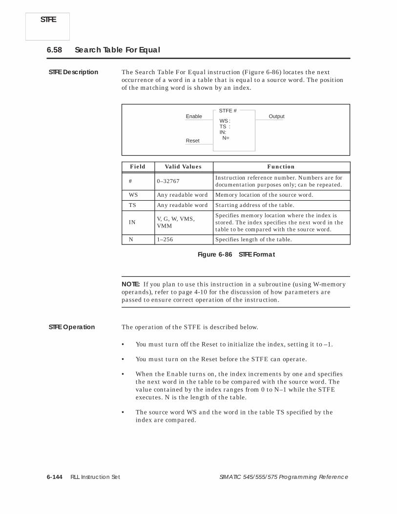
RLL Instruction Set6-144 SIMATIC 545/555/575 Programming Reference
6.58 Search Table For Equal
The Search Table For Equal instruction (Figure 6-86) locates the nextoccurrence of a word in a table that is equal to a source word. The positionof the matching word is shown by an index.
STFE #
WS :TS :IN:N=
OutputEnable
Reset
Field Valid Values Function
# 0–32767 Instruction reference number. Numbers are fordocumentation purposes only; can be repeated.
WS Any readable word Memory location of the source word.
TS Any readable word Starting address of the table.
IN V, G, W, VMS,VMM
Specifies memory location where the index isstored. The index specifies the next word in thetable to be compared with the source word.
N 1–256 Specifies length of the table.
Figure 6-86 STFE Format
NOTE: If you plan to use this instruction in a subroutine (using W-memoryoperands), refer to page 4-10 for the discussion of how parameters arepassed to ensure correct operation of the instruction.
The operation of the STFE is described below.
• You must turn off the Reset to initialize the index, setting it to –1.
• You must turn on the Reset before the STFE can operate.
• When the Enable turns on, the index increments by one and specifiesthe next word in the table to be compared with the source word. Thevalue contained by the index ranges from 0 to N–1 while the STFEexecutes. N is the length of the table.
• The source word WS and the word in the table TS specified by theindex are compared.
STFE
STFE Description
STFE Operation

RLL Instruction Set 6-145SIMATIC 545/555/575 Programming Reference
• If the two words are equal, the STFE output turns on for one scan andthen turns off.
The index contains the position of the matching word in the table forthe duration of this scan. The contents of the index must be used orsaved during this scan since the STFE looks for the next match on thenext scan as long as the Enable and Reset remain on.
• If the two words are not equal, the index increments by one and thenext word in the table is compared to the source word.
• If no matches are found in the table, the output remains off. The indexcontains the position of the last word in the table.
• The entire table is searched during one scan until one match or nomatch is found.
• If the Enable turns off while the Reset is on, the index holds its currentvalue. If the Reset turns off, the index resets to –1.
• After the entire table has been searched, i.e., the output is off and theindex = N–1, the STFE must be reset (Reset turns off) in order to beexecuted again.
If the Reset is off, the instruction does not execute, and there is no powerflow at the box output.
These RLL instructions are also used for table operations.
MIRFT MIRTT STFN TAND TCPL TOR
TTOW TXOR WTOT WTTA WTTO WTTXO
See Also
STFE

RLL Instruction Set6-146 SIMATIC 545/555/575 Programming Reference
6.59 Search Table For Not Equal
The Search Table For Not Equal instruction (Figure 6-87) locates the nextoccurrence of a word in a table that is not equal to a source word. Theposition of the non-matching word is shown by an index, and the value ofthe non-matching word is copied into a specified memory location.
STFN #
WS :TS :IN :WO:N=
Enable Output
Reset
Field Valid Values Function
# 0–32767 Instruction reference number. Numbers are fordocumentation purposes only; can be repeated.
WS Any readable word Memory location of the source word.
TS Any readable word Starting address of the table.
IN V, G, W, VMS,VMM
Specifies memory location where the index isstored. The index specifies the next word in thetable to be compared with the source word.
WO Any writeableword
Memory location to which the non-matchingword is written.
N 1–256 Specifies length of the table.
Figure 6-87 STFN Format
NOTE: If you plan to use this instruction in a subroutine (using W-memoryoperands), refer to page 4-10 for the discussion of how parameters arepassed to ensure correct operation of the instruction.
The operation of the STFN is described below.
• You must turn off the Reset to initialize the index, setting it to –1.
• You must turn on the Reset before the STFN can operate.
• When the Enable turns on, the index increments by one and specifiesthe next word in the table to be compared with the source word. Thevalue contained by the index ranges from 0 to N–1 while the STFNexecutes. N is the length of the table.
• The source word WS and the word in the table TS specified by theindex are compared.
STFN
STFN Description
STFN Operation

RLL Instruction Set 6-147SIMATIC 545/555/575 Programming Reference
• If the two words are not equal, the STFN output turns on for one scanand then turns off. The value of the non-matching word is copied intoanother memory location specified by WO.
The index contains the position of the non-matching word in the tablefor the duration of this scan. The contents of the index must be used orsaved during this scan since the STFN looks for the next match on thenext scan as long as the Enable and Reset remain on.
• If the two words are equal, the index increments by one and the nextword in the table is compared to the source word.
• If no mismatches are found in the table, the output remains off. Theindex contains the position of the last word in the table.
• The entire table is searched during one scan until one mismatch or nomismatch is found.
• If the Enable turns off while the Reset is on, the index holds its currentvalue. If the Reset does turn off, the index resets to –1.
• After the entire table has been searched, i.e., the output is off and theindex = N–1, the STFN must be reset (Reset turns off) in order to beexecuted again.
If the Reset is off, the instruction is not executed, and there is no power flowat the box output.
These RLL instructions are also used for table operations.
MIRFT MIRTT STFE TAND TCPL TOR
TTOW TXOR WTOT WTTA WTTO WTTXO
See Also
STFN

RLL Instruction Set6-148 SIMATIC 545/555/575 Programming Reference
6.60 Subtract
The Subtract instruction (Figure 6-88) subtracts a signed integer in memorylocation B from a signed integer in memory location A, and stores the resultin memory location C.
SUB #
A :B :C :
Input Output
Field Valid Values Function
# 0–32767 Instruction reference number. Numbers are fordocumentation purposes only; can be repeated.
AAny readable word Memory location for the minuend (a word), the
number from which a value is subtracted.A
or constant(–32768 to +32767)
Value of the minuend if a constant is used.A and B cannot both be constants.
BAny readable word Memory location for the subtrahend (a word),
the number that is subtracted.B
or constant(–32768 to +32767)
Value of the subtrahend if a constant is used.A and B cannot both be constants.
C Any writeableword
Memory location for the result (a word).
Figure 6-88 SUB Format
When the input is on, the SUB box executes. If the input remains on, theinstruction executes on every scan. The operation executed is C = A – B.
If –32768 ≤ result ≤ 32767, then the output turns on. Otherwise, theoutput turns off, and the least significant (16 bits) of the result arestored in C.
If the input is off, the instruction does not execute, and there is no powerflow at the box output.
These RLL instructions can also be used for math operations.
ABSV ADD CMP DIV MULT SQRT
Relational Contact
SUB
SUB Description
SUB Operation
See Also

RLL Instruction Set 6-149SIMATIC 545/555/575 Programming Reference
6.61 Table to Table AND
The Table to Table AND instruction (Figure 6-89) ANDs the correspondingbits in two tables and places the results in a specified third table. If bothbits are 1s, then the resultant bit is set to 1. Otherwise, the resultant bit isset to 0.
TAND #
T1 :T2 :TD :N=
Input Output
Field Valid Values Function
# 0–32767 Instruction reference number. Numbers are fordocumentation purposes only; can be repeated.
T1 Any readable word Starting address for the first table.
T2 Any readable word Starting address for the second table.
TD Any writeableword
Starting address for the destination table. TDcan be the same as T1 or T2, or be different.
N 1–256 Specifies table length. All tables are N wordslong.
Note: If you plan to use this instruction in a subroutine, refer to page 4-10 for the discussionof how parameters are passed to ensure correct operation of the instruction.
Figure 6-89 TAND Format
The operation of the TAND follows.
• When the input turns on, a comparison is made between each bit ofeach word in the first (T1) and second (T2) tables.
• Each pair of bits is ANDed, and the resultant bit is placed in the thirdtable (TD). If both bits are 1s, then the resultant bit is set to 1.Otherwise, the resultant bit is set to 0.
• The bits in all the words of the two tables are ANDed each scan.
• The output turns on when the instruction executes.
If the input is off, the instruction does not execute, and there is no powerflow at the box output.
These RLL instructions are also used for table operations.
MIRFT MIRTT STFE STFN TCPL TOR
TTOW TXOR WTOT WTTA WTTO WTTXO
TAND Description
TAND Operation
See Also
TAND

RLL Instruction Set6-150 SIMATIC 545/555/575 Programming Reference
6.62 Start New RLL Task
Use the TASK instruction (Figure 6-90) to delimit the main (I/Osynchronous) RLL task and the cyclic RLL task.
TASK #
A:
Field Valid Values Function
# 1, 2, 8 Designates task. 1 = normal RLL task;2 = cyclic RLL task; 8 = interrupt RLL task
A:0–32767 or anyreadable word thatcontains 0–65535.
Specifies cycle time in milliseconds. Allsegments for a TASK2 are executed within thecycle time specified in the TASK instruction forthe first TASK2 segment. Values specified in Afor subsequent segments are ignored.For TASK2, a value of 0 indicates that default(10) is used. A must set to 0 for TASK1 and TASK8. The datafile will not be displayed for TASK1 and TASK8except during edit.
Figure 6-90 TASK Format
The operation of the TASK is described below.
• The TASKn instruction indicates that the RLL instructions that followit comprise an RLL task segment, where n = 1 designates segments ofthe main RLL task, n = 2 designates segments of the cyclic RLL task,and n = 8 designates segments of the interrupt task. Refer toFigure 6-91a.
Task 1 is assumed when the first rung does not contain a TASKinstruction. A task can consist of multiple segments, each preceded by aTASK instruction. The segments do not have to be contiguous(Figure 6-91b). Terminate an RLL task with another TASK instructionor with the END instruction.
• TASK2 is executed with a higher priority than TASK1. Therefore,normal RLL execution is interrupted by a cyclic RLL task.
• TASK8 is executed with a higher priority than TASK1 or TASK2.Therefore, both the normal RLL and the cyclic RLL are interrupted bya configured I/O interrupt.
TASK
TASK Description
TASK Operation

RLL Instruction Set 6-151SIMATIC 545/555/575 Programming Reference
• If you specify the cycle time A for a TASK2 task as a readable word,you can change the cycle time on a cycle-by-cycle basis. When A = 0, thedefault time of 10 ms is used.
! CAUTIONUse caution in determining the time requirements for a cyclic task.
As the ratio of execution time to cycle time approaches 1:1, the risk increasesthat the main RLL task reports a scan watchdog Fatal Error , causing thecontroller to enter the Fatal Error mode, freeze analog outputs and turn offdiscrete outputs, which could lead to equipment failure.
You need to assess the time requirements for a cyclic task with care.
End
Task 1
Task 1main RLLprogram
Task 2
Task 2cyclic RLL
task
RLLsubroutines
Figure 6-91aTwo Unsegmented Tasks and RLL Subroutines
End
Task 1segment 1
Task 1
Task 1segment 2
Figure 6-91bTwo Segmented Tasks
Task 2
Task 2segment 1
Task 2
Task 2segment 2
Figure 6-91 Examples of TASK Design
TASK

RLL Instruction Set6-152 SIMATIC 545/555/575 Programming Reference
Start New RLL Task (continued)
• When the normal RLL task fails to complete execution within thespecified cycle time, bit 1 is set in STW219, and bit 14 is set in STW1on the next TASK1 scan. When the cyclic RLL task fails to completeexecution within the specified cycle time, bit 2 is set in STW219 on thenext TASK2 scan. When a cyclic task overruns, the cycle on which theoverrun is detected, is skipped. For example, a 3-ms task that overrunsthen executes at a 6-ms cycle rate.
You can display the peak execution time for a task using an operatorinterface and specifying TPET1 for TASK1 and TPET2 for TASK2.
• You can call any subroutine from a task and the normal subroutinenesting rules apply. Call a given subroutine from only one task.Subroutines are not re-entrant, and subroutine execution initiated byone task interferes with subroutine execution initiated by a secondtask.
These RLL instructions can also be used for immediate I/O applications.
Immediate Contact/Coil Immediate Set/Reset Coil IORW
Refer to Section 3.3 for more information about using TASK in a program.
TASK
See Also

RLL Instruction Set 6-153SIMATIC 545/555/575 Programming Reference
6.63 Time Compare
The Time Compare instruction (Figure 6-92) compares current time in thereal-time clock with values in the designated V-Memory locations.
TCMP #
TM :LT :GT :
Input Output
Field Valid Values Function
# 0–32767 Instruction reference number. Numbers are fordocumentation purposes only; can be repeated.
TM V, G, W, VMS,VMM
Specifies the memory locations containing timeto be compared to time in real-time clock.
V(TM) = Hour — BCD* 0000–0023.
V(TM+1) = Minute — BCD* 0000–0059.
V(TM+2) = Second — BCD* 0000–0059.
Enter the hexadecimal value of 00FF for any ofthe fields (hour, minute, second, etc.) that youwant to exclude from the compare operation.
LT Y, C, B, or blank Bit turned on when time represented in TMlocations < the real-time value in the clock.
GT Y, C, B, or blank Bit turned on when time represented in TMlocations > the real-time value in the clock.
Note: If you plan to use this instruction in a subroutine, refer to page 4-10 for the discussionof how parameters are passed to ensure correct operation of the instruction.
* BCD values are entered using the HEX data format.
Figure 6-92 TCMP Format
When there is power flow to the input of the TCMP instruction, the currenthours, minutes, and seconds in the real-time clock are compared to thevalues in the designated memory locations.
If a match occurs, the output of the instruction turns on. If the timerepresented by the memory locations is less than the real-time value in theclock, the bit designated by LT turns on. If the time represented by thememory locations is greater than the real-time value in the clock, the bitdesignated by GT turns on.
When the input is off, the comparison does not execute and there is nopower flow at the box output.
These RLL instructions can also be used for date/time functions.
DCMP DSET TSET
TCMP Description
TCMP Operation
See Also
TCMP

RLL Instruction Set6-154 SIMATIC 545/555/575 Programming Reference
6.64 Table Complement
The Table Complement (Figure 6-93) inverts the status of each bit in a tableand places the results in another specified table.
TCPL #
TS :TD :N=
Input Output
Field Valid Values Function
# 0–32767 Instruction reference number. Numbers are fordocumentation purposes only; can be repeated.
TS Any readable word Starting address of the table containing the bitsto be inverted.
TD Any writeableword
Starting address of the destination table. TDcan be the same as TS or be different.
N 1–256 Specifies length for both tables.
Figure 6-93 TCPL Format
The operation of the TCPL is described below.
• When the input turns on, each bit in the source table specified by TSinverts and stores in the destination table specified by TD.
0 inverted is 1; 1 inverted is 0.
• The bits in all the words of the table are inverted each scan.
• The output turns on when the instruction executes.
If the input is off, the instruction does not execute, and there is no powerflow at the box output.
These RLL instructions are also used for table operations.
MIRFT MIRTT STFE STFN TAND TOR
TTOW TXOR WTOT WTTA WTTO WTTXO
TCPL
TCPL Description
TCPL Operation
See Also

RLL Instruction Set 6-155SIMATIC 545/555/575 Programming Reference
6.65 Text
The Text box allows you to place textual information, such as copyright,software version, or other text into your RLL program. The instructionforms a single network and takes no action. The Text Box’s sole purpose isfor documentation.
The text box (Figure 6-94) can hold up to five lines of 40 characters each.Characters allowed in the text box are: A through Z, 0 through 9, space, andprintable special characters.
TEXT #
PROGRAM: UNIT 6 CONTROL
VERSION: 1.3
COPYRIGHT: 1994 ABC, INC.
DESCRIPTION: CONTROL
UNIT 6 OF THE WIDGET
Figure 6-94 Text Box Format
Text BoxDescription
TEXT

RLL Instruction Set6-156 SIMATIC 545/555/575 Programming Reference
6.66 Timer
The Timer instruction (Figure 6-95) is used to time events. The timer outputturns on after the timer times down, making this an “on delay” timer. A fasttimer is denoted by the mnemonic TMRF; a slow timer is denoted by TMR.
TMR #
P :
Start/StopOutput
Enable/Reset
Field Valid Values Function
# Varies withconfigured memory
Instruction reference number. Refer tocontroller user manual for number supported.The assigned instruction number must conformto the requirements of timer/counter memorydiscussed on page 4-5 in Section 4.2.
P 0–32767
Preset value from which the timer times down.P ranges from 0.000 to 32.767 seconds for a fast(1 ms) timer, and from 0.0 to 3276.7 seconds fora slow (.1 second) timer.
Figure 6-95 TMR/TMRF Format
The timer times down from the value specified in the preset, P. The preset isstored in TCP-Memory. The timer’s current time is stored in TCC-Memory.
• The Enable/Reset must be on for the timer to operate.
• When the Start/Stop input is on and the Enable/Reset is on, the timerbegins to time down.
• Timing begins at the preset value P and continues down to zero.
• If the Start/Stop input turns off and the Enable/Reset input remainson, the timer stops but it saves the current value, TCC. If theStart/Stop input turns on again, the timer resumes timing.
TCC is also saved if the Enable/Reset input is on and a loss of poweroccurs, provided the controller battery backup is enabled.
TMR/TMRF
TMR/TMRFDescription
TMR/TMRFOperation

RLL Instruction Set 6-157SIMATIC 545/555/575 Programming Reference
• If the Enable/Reset input turns off, the timer resets to the preset timespecified in P.
• The output turns on when the timer reaches zero, and it stays on untilthe timer resets; i.e., the Enable/Reset input turns off.
If the Enable/Reset does not receive power flow, the instruction does notexecute and the output does not turn on.
You can use other RLL instructions to read from or write to the timervariables. You can also use an operator interface to read or write to thetimer variables. While you are programming the timer, you are given theoption of protecting the preset values from changes made with an operatorinterface.
These RLL instructions are also used for electro-mechanical replacement.
Contacts Coils CTR DCAT DRUM EDRUM
JMP MCAT MCR MDRMD MDRMW NOT
SHRB SKP/LBL UDC
Refer to Section E.3 for an application example of the timer.
Using the TimerVariables
See Also
TMR/TMRF

RLL Instruction Set6-158 SIMATIC 545/555/575 Programming Reference
6.67 Table to Table OR
The Table to Table OR instruction (Figure 6-96) ORs the corresponding bitsin two tables and places the results in a specified third table. If either bitis 1, then the resultant bit is set to 1. Otherwise, the resultant bit is set to 0.
TOR #
T1 :T2 :TD :N=
Input Output
Field Valid Values Function
# 0–32767 Instruction reference number. Numbers are fordocumentation purposes only; can be repeated.
T1 Any readable word Starting address for the first table.
T2 Any readable word Starting address for the second table.
TD Any writeableword
Starting address for the destination table. TDcan be the same as T1 or T2, or be different.
N 1–256 Specifies table length. All tables are N wordslong.
Note: If you plan to use this instruction in a subroutine, refer to page 4-10 for the discussionof how parameters are passed to ensure correct operation of the instruction.
Figure 6-96 TOR Format
The operation of the TOR is described below.
• When the input turns on, a comparison is made between each bit ofeach word in the first (T1) and second (T2) tables.
• Each pair of bits is ORed, and the resultant bit is placed in the thirdtable (TD). If either bit is 1, then the resultant bit is set to 1.Otherwise, the resultant bit is set to 0.
• The bits in all the words of the two tables are ORed each scan.
• The output is turned on when the instruction is executed.
If the input is off, the instruction is not executed, and there is no power flowat the box output.
These RLL instructions are also used for table operations.
MIRFT MIRTT STFE STFN TAND TCPL
TTOW TXOR WTOT WTTA WTTO WTTXO
TOR
TOR Description
TOR Operation
See Also

RLL Instruction Set 6-159SIMATIC 545/555/575 Programming Reference
6.68 Time Set
The Time Set instruction (Figure 6-97) sets the time portion of the real-timeclock to the values contained in designated memory locations.
TSET #
TM :
Input Output
Field Valid Values Function
# 1 to number of oneshots.
Instruction reference number. The TSET usesone shot memory. The assigned instructionnumber must conform to the requirements ofone-shot memory discussed on page 4-7 inSection 4.2. Each TSET instruction must have aunique number.
TM V, G, W, VMS,VMM
Designates the memory locations containingtime to be written into the real-time clock.*
V(TM) = Hours — BCD value 0000–0023.
V(TM+1) = Minutes — BCD value 0000–0059.
V(TM+2) = Seconds — BCD value 0000–0059.
Note: If you plan to use this instruction in a subroutine, refer to page 4-10 for the discussionof how parameters are passed to ensure correct operation of the instruction.
* BCD values are entered using the HEX data format.
Figure 6-97 TSET Format
When the input to the TSET instruction transitions from off to on, the timeportion of the real-time clock is set to the values contained within the threeconsecutive V-Memory locations designated by TM, and the output turns onfor one scan.
NOTE: The time of day status words (STW141–144 and STW223–225) donot reflect the time change until the next RLL scan.
When the input is off, the operation does not execute, and there is no powerflow at the box output.
These RLL instructions can also be used for date/time functions.
DCMP DSET TCMP
TSET Description
TSET Operation
See Also
TSET

RLL Instruction Set6-160 SIMATIC 545/555/575 Programming Reference
6.69 Table to Word
The Table to Word instruction (Figure 6-98) copies a word in a table andplaces it in another memory location.
TTOW #
WD:TS :IN :N=
EnableOutput
Reset
Field Valid Values Function
# 0–32767 Instruction reference number. Numbers are fordocumentation purposes only; can be repeated.
WD Any writeableword
Memory location for destination of the word.
TS Any readable word Starting address of source table.
IN V, G, W, VMS,VMM
Specifies memory location where index is stored.The index indicates which word in the table iscopied.
N 1–256 Length of table in words.
Figure 6-98 TTOW Format
NOTE: If you plan to use this instruction in a subroutine (using W-memoryoperands), refer to page 4-10 for the discussion of how parameters arepassed to ensure correct operation of the instruction.
TTOW
TTOW Description

RLL Instruction Set 6-161SIMATIC 545/555/575 Programming Reference
The operation of the TTOW is described below.
• The Reset must be on for the instruction to execute.
• When the Enable turns on, a copy is made of the specified word in thetable TS.
The index (IN) indicates which word in the table is copied. The valuecontained by the index ranges from 0 to N–1, where N is the length ofthe table. If 0 ≤ IN < N, the word is copied. If N ≤ IN or N < 0, the wordis not copied.
• The word is placed in the memory location specified by WD. After theword is placed there, the value contained by the index increments byone.
• If both Enable and Reset remain on, one word is duplicated each scan.
• If the Enable turns off while the Reset is on, the index holds its currentvalue and the word is not moved.
If the Reset turns off, the index resets to 0.
• The TTOW output remains on until the last word in the table is copied.It then turns off.
• The TTOW must be reset (Reset turns off) after the output turns off inorder to execute again.
If the Reset is off, the instruction does not execute, and there is no powerflow at the box output.
These RLL instructions are also used for table operations.
MIRFT MIRTT STFE STFN TAND TCPL
TOR TXOR WTOT WTTA WTTO WTTXO
TTOW Operation
See Also
TTOW

RLL Instruction Set6-162 SIMATIC 545/555/575 Programming Reference
6.70 Table to Table Exclusive OR
The Table to Table Exclusive OR instruction (Figure 6-99) executes anExclusive OR on the corresponding bits in two tables and places the resultsin a specified third table. If the bits compared are the same, the resultantbit is set to a 0. If the bits compared are different, the resultant bit is setto 1.
TXOR #
T1 :T2 :TD :N=
Input Output
Field Valid Values Function
# 0–32767 Instruction reference number. Numbers are fordocumentation purposes only; can be repeated.
T1 Any readable word Starting address of the first table.
T2 Any readable word Starting address of the second table.
TD Any writeableword
Starting address of the destination table. TDcan be the same as T1 or T2, or can be different.
N 1–256 Table length. All tables are N words long.
Figure 6-99 TXOR Format
NOTE: If you plan to use this instruction in a subroutine (using W-memoryoperands), refer to page 4-10 for the discussion of how parameters arepassed to ensure correct operation of the instruction.
TXOR
TXOR Description

RLL Instruction Set 6-163SIMATIC 545/555/575 Programming Reference
The operation of the TXOR is described below.
• When the input turns on, a comparison is made between each bit ofeach word in the first (T1) and second (T2) tables.
• An Exclusive OR is executed on each pair of bits, and the resultant bitis placed in the third table (TD). If the bits compared are either both 1sor both 0s, the resultant bit is set to a 0. If the bits compared are unlike(1 and 0), the resultant bit is set to 1.
• An Exclusive OR is executed on the bits in all the words of the twotables each scan.
• The output turns on when the instruction executes.
If the input is off, the instruction does not execute, and there is no powerflow at the box output.
These RLL instructions are also used for table operations.
MIRFT MIRTT STFE STFN TAND TCPL
TOR TTOW WTOT WTTA WTTO WTTXO
TXOR Operation
See Also
TXOR

RLL Instruction Set6-164 SIMATIC 545/555/575 Programming Reference
6.71 Up/Down Counter
The Up-Down Counter instruction (Figure 6-100) counts the number ofevents (up or down) from 0 to 32,767.
UDC #
P=
Z:
UpOutput
Enable/Reset
Down
Field Valid Values Function
# Varies withcontroller model
Instruction reference number. Refer to controlleruser manual for number supported. The assignedinstruction number must conform to therequirements of timer/counter memory discussedon page 4-5 in Section 4.2.
P 0–32767 Preset maximum value to which the UDC counts.The UDC does not count events beyond P.
Z Y, C, B, or blank Address of the coil to be turned on when thecurrent count is equal to zero.
Figure 6-100 UDC Format
UDC
UDC Description

RLL Instruction Set 6-165SIMATIC 545/555/575 Programming Reference
When the counter counts up, it counts to the preset value specified in P, thatis stored in TCP-Memory. The current count is stored in TCC-Memory.
• The Enable/Reset must be on for the counter to operate.
• When the Enable/Reset is on, the counter increments by one when theUp input transitions from off to on.
• When the Enable/Reset is on, the counter decrements by one when theDown input transitions from off to on. The UDC does not decrement toa number less than zero.
• TCC does not change if the Up and Down inputs both change from offto on during the same scan.
• If the Enable/Reset turns off, TCC resets to zero.
• The output specified in Z turns on whenever TCC equals zero. Thisoutput turns off when TCC does not equal zero.
• The box output turns on whenever TCC equals zero or TCP.
• After having counted to the preset value (TCP), the box does notrequire resetting in order to resume counting in the opposite direction.TCC does not ever exceed TCP.
If the Enable/Reset does not receive power flow, the instruction does notexecute and the output does not turn on.
UDC Operation
UDC

RLL Instruction Set6-166 SIMATIC 545/555/575 Programming Reference
Up/Down Counter (continued)
Other RLL instructions can be used to read from or write to the UDCvariables. You can also use an operator interface to read from or write to theUDC variables. While you are programming the UDC, you are given theoption of protecting the preset values from changes made with an operatorinterface.
NOTE: If you use an operator interface to change TCP, the new TCP value isnot changed in the original RLL program. If the RLL presets are everdownloaded the changes made with the operator interface are replaced bythe original values in the RLL program.
These RLL instructions are also used for electromechanical replacement.
Contacts Coils CTR DCAT DRUM EDRUM
JMP MCAT MCR MDRMD MDRMW NOT
SHRB SKP/LBL TMR
UDC
Using the UDCVariables
See Also

RLL Instruction Set 6-167SIMATIC 545/555/575 Programming Reference
6.72 Unlock Memory
The Unlock instruction (Figure 6-101), works with the LOCK instruction toprovide a means whereby multiple applications in the 575 systemcoordinate access to shared resources, generally G-Memory data blocks.
UNLCK #
AA :Input Output
Field Valid Values Function
# 0–32767 Instruction reference number. Numbers fordocumentation purposes only; can be repeated.
AA G, VMS, VMMMemory location (2 words) where lock structureis stored. Use same address for associatedLOCK instruction.
Figure 6-101 UNLCK Format
Refer to Section 6.28 for a description of how UNLCK works with the LOCKinstruction.
This RLL instruction is also used to coordinate access to shared resources.
LOCK
UNLCK Description
UNLCK Operation
See Also
UNLCK575

RLL Instruction Set6-168 SIMATIC 545/555/575 Programming Reference
6.73 Word AND
The Word AND instruction (Figure 6-102) logically ANDs a word in memorylocation A with a word in memory location B, bit for bit. The result is storedin memory location C.
WAND #
A :B :C :
Input Output
Field Valid Values Function
# 0–32767 Instruction reference number. Numbers are fordocumentation purposes only; can be repeated.
A Any readable word Memory location of the first word in the ANDoperation.
BAny readable word Memory location of the second word in the AND
operation.B
or constant(–32768 to +32767)
Value of the second word when a constant isused.
C Any writeableword
Memory location where the result is stored.
Figure 6-102 WAND Format
When the input turns on, the instruction executes. If the input remains on,the instruction is executed on every scan.
• The word stored in the memory location specified by A is ANDed withthe word stored in the memory location specified by B. The operation isdone bit by bit, as illustrated in Figure 6-103.
The words in A and B are not affected by the WAND instruction andretain their original values.
A B C
0 0 0
0 1 0
1 0 0
1 1 1
For each bit location A and B,the result of an AND operation is given in C.
Figure 6-103 Result of ANDing Bits
WAND
WAND Description
WAND Operation

RLL Instruction Set 6-169SIMATIC 545/555/575 Programming Reference
• The result is stored in the memory location specified by C, asillustrated in Figure 6-104.
1 2 3 4 5 6 7 8 9 10 11 12 13 14 15 16Bit
0 1 0 1 0 0 0 1 0 0 0 0 0 0 0 1
0 1 0 1 0 0 0 1 0 0 0 0 0 0 0 1
1 1 0 1 1 1 1 1 1 1 1 1 0 0 0 1
The word in A is ANDed withthe word in B. The result isstored in C.
A
B
C
Figure 6-104 Result of ANDing Two Words
• If C is not zero, the output turns on when the instruction executes.
• If C is zero, the output turns off.
If the input is off, the instruction does not execute, and there is no powerflow at the box output.
These RLL instructions are also used for bit manipulation.
BITC BITS BITP IMC SMC WOR
WROT WXOR Bit-of-Word Contact/Coil
See Also
WAND

RLL Instruction Set6-170 SIMATIC 545/555/575 Programming Reference
6.74 Word OR
The Word OR instruction (Figure 6-105) logically ORs a word in memorylocation A with a word in memory location B. The result is stored in memorylocation C.
WOR #
A :B :C :
Input Output
Field Valid Values Function
# 0–32767 Instruction reference number. Numbers are fordocumentation purposes only; can be repeated.
A Any readable word Memory location of the first word in the ORoperation.
BAny readable word Memory location of the second word in the OR
operation.B
or constant(–32768 to +32767)
Value of the second word when a constant isused.
C Any writeableword
Memory location where the result is stored.
Figure 6-105 WOR Format
When the input is on, the WOR box executes. If the input remains on, theinstruction executes on every scan.
• The word stored in the memory location specified by A is ORed with theword stored in the memory location specified by B. The operation isdone bit by bit, as illustrated in Figure 6-106.
The words in A and B are not affected by the OR instruction and retaintheir original values.
A B C
0 0 0
0 1 1
1 0 1
1 1 1
For each bit location A and B,the result of an OR operation is given in C.
Figure 6-106 Result of ORing Bits
WOR
WOR Description
WOR Operation

RLL Instruction Set 6-171SIMATIC 545/555/575 Programming Reference
• The result is stored in the memory location specified by C, asillustrated in Figure 6-107.
1 2 3 4 5 6 7 8 9 10 11 12 13 14 15 16Bit
0 1 0 1 0 0 0 1 0 0 0 0 0 0 0 1
1 1 0 1 1 1 1 1 1 1 1 1 0 0 0 1
1 1 0 1 1 1 1 1 1 1 1 1 0 0 0 1
A
B
C
The word in A is ORedwith the word in B, andthe result is stored in C.
Figure 6-107 Result of ORing Two Words
• If C is not zero, the output turns on when the instruction executes.
• If C is zero, the output turns off.
If the input is off, the instruction does not executes, and there is no powerflow at the box output.
These RLL instructions are also used for bit manipulation.
BITC BITS BITP IMC SMC WAND
WROT WXOR Bit-of-Word Contact/Coil
See Also
WOR

RLL Instruction Set6-172 SIMATIC 545/555/575 Programming Reference
6.75 Word Rotate
The Word Rotate instruction (Figure 6-108) operates on the 4-bit segmentsof a word, rotating them to the right.
WROT #
A :N=
Input Output
Field Valid Values Function
# 0–32767 Instruction reference number. Numbers are fordocumentation purposes only; can be repeated.
A Any writeableword
Memory location of the word to be rotated.
N 1–3 Number of times that the 4-bit segments arerotated.
Figure 6-108 WROT Format
When the input is turned on, the WROT box executes. If the input remainson, the instruction executes on every scan.
• Each 4-bit segment of the word specified in memory location A shift tothe right as shown in Figure 6-109.
4-bitsegment
4-bitsegment
4-bitsegment
4-bitsegment
Figure 6-109 WROT Operation
WROT
WROT Description
WROT Operation

RLL Instruction Set 6-173SIMATIC 545/555/575 Programming Reference
• A segment can shift up to 3 positions as specified by N. SeeFigure 6-110.
• If A is not zero, the output turns on when the instruction executes.
• If A is zero, the output turns off.
If the input is off, the instruction does not executes, and there is no powerflow at the box output.
0010 1000 0110 0111
0111 0010 1000 0110
N = 1
The following word is rotated as shown:
0010 1000 0110 0111
1000 0110 0111 0010
N = 3
Figure 6-110 Result of a WROT Operation
These RLL instructions are also used for bit manipulation.
BITC BITS BITP IMC SMC WAND
WOR WXOR Bit-of-Word Contact/Coil
See Also
WROT

RLL Instruction Set6-174 SIMATIC 545/555/575 Programming Reference
6.76 Word To Table
The Word To Table instruction (Figure 6-111) places a copy of a word at aspecified address within a table.
WTOT #
WS :TD :IN :N=
Enable Output
Reset
Field Valid Values Function
# 0–32767 Instruction reference number. Numbers are fordocumentation purposes only; can be repeated.
WS Any readable word Memory location of the source word.
TD Any writeableword
Starting address of the table.
IN V, G, W, VMS,VMM
Specifies memory location where the index isstored. The index specifies where the word isplaced in the table.
N 1–256 Specifies length of the table.
Figure 6-111 WTOT Format
NOTE: If you plan to use this instruction in a subroutine (using W-memoryoperands), refer to page 4-10 for the discussion of how parameters arepassed to ensure correct operation of the instruction.
WTOT
WTOT Description

RLL Instruction Set 6-175SIMATIC 545/555/575 Programming Reference
The operation of the WTOT is described below.
• The Reset must be on for the instruction to execute.
• When the Enable turns on, a copy of the source word WS is placed inthe destination table TD.
The index (IN) indicates where the word is placed in the table. Thevalue contained by the index ranges from 0 to N–1, where N is thelength of the table. If 0 ≤ IN < N, the word is moved. If N ≤ IN orN < 0, the word is not moved.
• After the word is placed into the table, the value contained by the indexincrements by one.
• If both Enable and Reset remain on, one word is moved each scan.
• If the Enable turns off while the Reset is on, the index holds its currentvalue and the word is not moved.
If the Reset turns off, the index resets to 0.
• The WTOT output remains on until a word is placed in the last positionin the table. It then turns off.
• The WTOT must be reset (Reset turns off) after the output turns off, inorder to execute again.
If the Reset is off, the instruction does not execute, and there is no powerflow at the box output.
These RLL instructions are also used for table operations.
MIRFT MIRTT STFE STFN TAND TCPL
TOR TTOW TXOR WTTA WTTO WTTXO
WTOT Operation
See Also
WTOT

RLL Instruction Set6-176 SIMATIC 545/555/575 Programming Reference
6.77 Word To Table AND
The Word To Table AND instruction (Figure 6-112) ANDs each bit in asource word with the corresponding bit of a designated word in a table. Theresults are placed in a destination table. If both bits are 1s, a 1 is stored inthe destination table. Otherwise, the resultant bit is set to 0.
WTTA #
WS :TS :TD :IN :N=
Enable Output
Reset
Field Valid Values Function
# 0–32767 Instruction reference number. Numbers are fordocumentation purposes only; can be repeated.
WS Any readable word Memory location of the source word.
TS Any readable word Starting address of the source table.
TD Any writeableword
Starting address of the destination table. TDcan be the same as TS or can be different.
IN V, G, W, VMS,VMM
Specifies memory location where the index isstored. The index specifies that word in thetable is ANDed.
N 1–256 Specifies length of the table.
Figure 6-112 WTTA Format
NOTE: If you plan to use this instruction in a subroutine (using W-memoryoperands), refer to page 4-10 for the discussion of how parameters arepassed to ensure correct operation of the instruction.
WTTA
WTTA Description

RLL Instruction Set 6-177SIMATIC 545/555/575 Programming Reference
The operation of the WTTA is described below.
• The Reset must be on for the instruction to execute.
• When the Enable turns on, each bit of the source word WS and of aspecified word in the table TS is compared.
The index (IN) indicates which word in the table is ANDed. The valuecontained by the index ranges from 0 to N–1, where N is the length ofthe table. If 0 ≤ IN < N, the word is ANDed. If N ≤ IN or N < 0, the word is not ANDed.
• Each pair of bits is ANDed, and the resultant bit is placed in thedestination table TD. If both bits are 1s, the resultant bit is set to 1.Otherwise, the resultant bit is set to 0.
After a word in the table is compared, the value contained by the indexincrements by one.
• If both Enable and Reset remain on, the source word and a word in thetable are ANDed each scan.
• If the Enable turns off while the Reset is on, the index holds its currentvalue and the AND does not occur.
If the Reset turns off, the index resets to 0.
• The WTTA output remains on until the last word in the table has beenANDed with the source word. It then turns off.
• The WTTA must be reset (Reset turns off) after the output turns off inorder to execute again.
If the Reset is off, the instruction does not execute, and there is no powerflow at the box output.
These RLL instructions are also used for table operations.
MIRFT MIRTT STFE STFN TAND TCPL
TOR TTOW TXOR WTOT WTTO WTTXO
WTTA Operation
See Also
WTTA

RLL Instruction Set6-178 SIMATIC 545/555/575 Programming Reference
6.78 Word To Table OR
The Word To Table OR instruction (Figure 6-113) ORs each bit in a sourceword with the corresponding bit of a designated word in a table. The resultsare placed in a destination table. If either bit is 1, a 1 is stored in thedestination table. Otherwise, the resultant bit is set to 0.
WTTO #
WS :TS :TD :IN :N=
Enable Output
Reset
Field Valid Values Function
# 0–32767 Instruction reference number. Numbers are fordocumentation purposes only; can be repeated.
WS Any readable word Memory location of the source word.
TS Any readable word Starting address of the source table.
TD Any writeableword
Starting address of the destination table. TDcan be the same as TS or can be different.
IN V, G, W, VMS,VMM
Specifies memory location where the index isstored. The index specifies which word in thetable is ORed.
N 1–256 Specifies length of the table.
Figure 6-113 WTTO Format
NOTE: If you plan to use this instruction in a subroutine (using W-memoryoperands), refer to page 4-10 for the discussion of how parameters arepassed to ensure correct operation of the instruction.
WTTO
WTTO Description

RLL Instruction Set 6-179SIMATIC 545/555/575 Programming Reference
The operation of the WTTO is described below.
• The Reset must be on for the instruction to execute.
• When the Enable turns on, each bit of the source word WS and of aspecified word in the table TS is compared.
The index (IN) indicates which word in the table is ORed. The valuecontained by the index ranges from 0 to N–1, where N is the length ofthe table. If 0 ≤ IN < N, the word is ORed. If N ≤ IN or N < 0, the word is not ORed.
• Each pair of bits is ORed, and the resultant bit is placed in thedestination table TD. If either bit is 1, then the resultant bit is set to 1.Otherwise, the resultant bit is set to 0.
After a word in the table is compared, the value contained by the indexincrements by one.
• If both Enable and Reset remain on, the source word and a word in thetable are ORed each scan.
• If the Enable turns off while the Reset is on, the index holds its currentvalue and the OR does not occur.
If the Reset turns off, the index resets to 0.
• The WTTO output remains on until the last word in the table has beenORed with the source word. It then turns off.
• The WTTO must be reset (Reset turns off) after the output turns off inorder to execute again.
If the Reset is off, the instruction does not execute, and there is no powerflow at the box output.
These RLL instructions are also used for table operations.
MIRFT MIRTT STFE STFN TAND TCPL
TOR TTOW TXOR WTOT WTTA WTTXO
WTTO Operation
See Also
WTTO

RLL Instruction Set6-180 SIMATIC 545/555/575 Programming Reference
6.79 Word To Table Exclusive OR
The Word To Table Exclusive OR (Figure 6-114) executes an Exclusive ORon each bit in a source word with the corresponding bit of a designated wordin a table. The results are placed in a destination table. If the bits comparedare the same, the resultant bit is set to a 0. Otherwise, the resultant bit isset to 1.
WTTXO #
WS :TS :TD :IN :N=
Enable Output
Reset
Field Valid Values Function
# 0–32767 Instruction reference number. Numbers are fordocumentation purposes only; can be repeated.
WS Any readable word Memory location of the source word.
TS Any readable word Starting address of the source table.
TD Any writeableword
Starting address of the destination table. TDcan be the same as TS or can be different.
IN V, G, W, VMS,VMM
Specifies memory location where the index isstored. The index specifies on which word in thetable that the Exclusive OR is executed.
N 1–256 Specifies length of the table.
Figure 6-114 WTTXO Format
NOTE: If you plan to use this instruction in a subroutine (using W-memoryoperands), refer to page 4-10 for the discussion of how parameters arepassed to ensure correct operation of the instruction.
WTTXO
WTTXO Description

RLL Instruction Set 6-181SIMATIC 545/555/575 Programming Reference
The operation of the WTTXO is described below.
• The Reset must be on for the instruction to execute.
• When the Enable turns on, each bit of the source word WS and of aspecified word in the table TS is compared.
The index (IN) indicates the word in the table on which theExclusive OR occurs. The value contained by the index ranges from 0 toN–1, where N is the length of the table. If 0 ≤ IN < N, the Exclusive ORtakes place. If N ≤ IN or N < 0, the Exclusive OR does not take place.
• An Exclusive OR is executed on each pair of bits, and the resultant bitis placed in the destination table TD. If the bits compared are the same,the resultant bit is set to a 0. If the bits compared are different, theresultant bit is set to 1.
After a word in the table is compared, the value contained by the indexincrements by one.
• If both Enable and Reset remain on, the Exclusive OR executes on thesource word and a word in the table each scan.
• If the Enable turns off while the Reset is on, the index holds its currentvalue and the Exclusive OR does not take place.
If the Reset turns off, the index resets to 0.
• The WTTXO output remains on until the last word in the table hasbeen compared with the source word. It then turns off.
• The WTTXO must be reset (Reset turns off) after the output turns offin order to execute again.
If the Reset is off, the instruction does not execute, and there is no powerflow at the box output.
These RLL instructions are also used for table operations.
MIRFT MIRTT STFE STFN TAND TCPL
TOR TTOW TXOR WTOT WTTA WTTO
WTTXO Operation
See Also
WTTXO

RLL Instruction Set6-182 SIMATIC 545/555/575 Programming Reference
6.80 Word Exclusive OR
The Word Exclusive OR instruction (Figure 6-115) executes a logicalExclusive OR on a word in memory location A with a word in memorylocation B. The result is stored in memory location C.
WXOR #
A :B :C :
Input Output
Field Valid Values Function
# 0–32767 Instruction reference number. Numbers are fordocumentation purposes only; can be repeated.
A Any readable word Memory location of the first word in theExclusive OR operation.
BAny readable word Memory location of the second word in the
Exclusive OR operation.B
or constant(–32768 to +32767)
Value of second word when a constant is used.
C Any writeableword
Memory location where the result is stored.
Figure 6-115 WXOR Format
When the input is turned on, the WXOR box execute. If the input remainson, the instruction executes on every scan.
• An Exclusive OR operation executes on the word stored in the memorylocation specified by A with the word stored in the memory locationspecified by B. The operation is done bit by bit, as illustrated inFigure 6-116.
• The words in A and B are not affected by the WXOR instruction andretain their original values.
WXOR
WXOR Description
WXOR Operation

RLL Instruction Set 6-183SIMATIC 545/555/575 Programming Reference
A B C
0 0 0
0 1 1
1 0 1
1 1 0
For each bit location A and B, theresult of an Exclusive OR operationis given in C.
Figure 6-116 Result of an Exclusive OR of Bits
• The result is stored in the memory location specified by C, asillustrated in Figure 6-117.
1 2 3 4 5 6 7 8 9 10 11 12 13 14 15 16Bit
0 1 0 1 0 0 0 1 0 0 0 0 0 0 0 1
1 0 0 0 1 1 1 0 1 1 1 1 0 0 0 0
1 1 0 1 1 1 1 1 1 1 1 1 0 0 0 1
A
B
C
An Exclusive OR operationis executed on the words inA and B and the result isstored in C.
Figure 6-117 Result of an Exclusive OR of Two Words
• If C is not zero, the output turns on when the instruction executes.
• If C is zero, the output turns off.
If the input is off, the instruction does not execute, and there is no powerflow at the box output.
These RLL instructions are also used for bit manipulation.
BITC BITS BITP IMC SMC WAND
WOR WROT Bit-of-Word Contact/Coil
Refer to Section E.11 for an application example of the WXOR.
See Also
WXOR

RLL Instruction Set6-184 SIMATIC 545/555/575 Programming Reference
6.81 External Subroutine Call
The XSUB (Figure 6-118) allows you to pass parameters to a subroutinethat is developed offline in a non-RLL programming language, such as C orPascal, and then call the subroutine for execution. Refer to Appendix H formore information about designing and writing external subroutines.
IN1 :IN2 :IN3 :IN4 :IN5 :IN6 :IN7 :IN8 :IN9 :IN10 :IN11 :IN12 :IN13 :IN14 :IN15 :IN16 :IN17 :IN18 :IN19 :IN20 :
XSUB #
Input
Field Valid Values Function
# 1–32767 Designates subroutine to call.
IN/IO
IN followed by anyreadable bit or word.
IO followed by anyreadable bit or word.
IN: Designates address that contains data tobe read by the subroutine.
IO: Designates an address to be passed to thesubroutine.
B and W locations are valid only when XSUBis used in a subroutine.
Figure 6-118 XSUB Format
NOTE: The parameter fields (IN1–IN20) allow read-only addresses, e.g., Kor WX, to be specified as I/O parameters. This allows you to pass the baseaddress of a read-only array to the subroutine. It is recommended that younot design the subroutine to alter the contents of the read-only variable(s)since other instructions assume that they do not change.
XSUB
XSUB Description

RLL Instruction Set 6-185SIMATIC 545/555/575 Programming Reference
! WARNINGWhen you call an external subroutine, the built-in protection features of thecontroller are by-passed. Take care in testing the external subroutine beforeintroducing it to a control environment.
Failure of the external subroutine may cause undetected corruption ofcontroller memory and unpredictable operation by the controller, which couldresult in death or serious injury to personnel, and/or damage to equipment.
You must be careful in testing the external subroutine before introducing it to acontrol environment.
The operation of the XSUB instruction is described below. See Figure 6-119.
• Parameters must be numbered consecutively, i.e., you cannot skipparameter numbers.
• When the input is turned on:
The parameters are pushed on the user stack, in order, from the lastparameter to the first parameter, and then the subroutine is called.This corresponds to the C language calling convention.
When a discrete data element (X, Y, C, B) is specified as an INparameter, the discrete value is passed in the least significant bit of along word. All other bits of the long word are unspecified (may be 0 or1).
When a discrete data element is specified as an IO parameter, theaddress of the data element is passed. The actual value of the dataelement is contained in the least significant bit of the byte at thisaddress. Other bits of this byte are unspecified.
When a word data element (V, K, etc.) is specified as an IN parameter,the value of the long word at this specified data element and thespecified data element + 1 (e.g., V100 and V101) is passed. Theaddressed word is in the most significant half, and the next consecutiveword is in the least significant half. Any readable data element isallowed.
When a word data element is specified as an IO parameter, the addressof the data element is passed. The value of the parameter is containedat this address.
After all parameters have been pushed onto the stack, the subroutine iscalled. If the subroutine successfully executes (see Notes below)STW01 bit 11 turns off, and the controller continues the scan with thenext network.
XSUB Operation
XSUB

RLL Instruction Set6-186 SIMATIC 545/555/575 Programming Reference
External Subroutine Call (continued)
IO1 C11IO2 V110IO3 K99IN4 8871
IN19IN20
END
XSUB 179
C100
L-memory
U-Memory
Before the XSUB is executed,assume the following valuesfor these memory locations:
C11 = 1V110,V111 = 0, 27706K99,K100 = 1948
When C100 = 1,
IO1 = C11 = 1IO2 = V110,V111 = 27706IO3 = K99,K100 = 1948IN = 8871
User-definedsubroutine # 179
Subroutine reads
IO1 = 1IO2 = address of V110IO3 = 1948IN4 = 8871
After execution that changesV110, V111 to 98250,
Subroutine returns control tothe RLL program.
When control returns to RLL,
C11 = unchangedV110,V111 = 98250K99,K100 = unchanged
Control passes tosubroutine.
Control passesto RLL.
Figure 6-119 Example of the XSUB Instruction
NOTE: An XSUB in RLL with no defined external subroutine causes theuser program error bit (6) and the instruction failed bit (11) to be set inSTW01, with the reason set to 6 in STW200 (if this is the first error logged).The controller remains in RUN mode.
XSUB

RLL Instruction Set 6-187SIMATIC 545/555/575 Programming Reference
NOTE: For the 575, if an XSUB instruction attempts to access anon-existent VMEbus address a VMEbus error occurs. If this is the firstVMEbus error, the offending VMEbus address is written toSTW227-STW228 and the U-Memory offset of the offending instruction iswritten to STW229-STW230.
If you set the U-Memory header’s E bit to 1 when you create your externalsubroutine(s), a VMEbus error will terminate the XSUB and continue RLLexecution with the network following the XSUB instruction. In this case theuser program error bit (6) and instruction failed bit (11) in STW01 are set to1 and, if this is the first user program error encountered on the current RLLscan, the value 7 (VMEbus error) is written to STW200.
! WARNINGIf you set the U-Memory header ’s E bit to 0 and a VMEbus error occurs duringexecution of an XSUB, the 575 controller will transition to the Fatal Error mode.The transition to Fatal Error mode freezes word outputs and clears discreteoutputs, which could cause unexpected process operation.
Unexpected process operation could result in death or serious injury topersonnel, and/or damage to equipment.
Avoid setting the U-Memory header ’s E bit to 0 when you create externalsubroutines.
• When the input is off, the instruction does not execute and thesubroutine is not called. Bit 11 of STW01 turns off.
These RLL instructions are also used for subroutine operations.
GTS PGTS PGTSZ RTN SBR SFPGM SFSUB
See Also
XSUB

Special Function Programs 7-1SIMATIC 545/555/575 Programming Reference
Chapter 7
Special Function Programs
7.1 Defining Special Function Programs 7-2. . . . . . . . . . . . . . . . . . . . . . . . . . . . . . . . . . . . . . . . . . . . . .
7.2 Using PowerMath with Special Function Programming 7-4. . . . . . . . . . . . . . . . . . . . . . . . . . . . .
7.3 SF Program Statements 7-10. . . . . . . . . . . . . . . . . . . . . . . . . . . . . . . . . . . . . . . . . . . . . . . . . . . . . . . . . .
7.4 Executing Special Function Programs 7-11. . . . . . . . . . . . . . . . . . . . . . . . . . . . . . . . . . . . . . . . . . . .
7.5 Executing Special Function Subroutines 7-14. . . . . . . . . . . . . . . . . . . . . . . . . . . . . . . . . . . . . . . . . .
7.6 Memory Usage by SF Programs 7-16. . . . . . . . . . . . . . . . . . . . . . . . . . . . . . . . . . . . . . . . . . . . . . . . . .
7.7 Entering SF Program Header with TISOFT 7-18. . . . . . . . . . . . . . . . . . . . . . . . . . . . . . . . . . . . . . . . . .
7.8 Reporting SF Program or SFSUB RLL Instruction Errors 7-20. . . . . . . . . . . . . . . . . . . . . . . . . . . . . . .
7.9 Entering Special Function Programming Statements 7-22. . . . . . . . . . . . . . . . . . . . . . . . . . . . . . .
7.10 Convert BCD to Binary 7-24. . . . . . . . . . . . . . . . . . . . . . . . . . . . . . . . . . . . . . . . . . . . . . . . . . . . . . . . . .
7.11 Convert Binary Inputs to BCD 7-25. . . . . . . . . . . . . . . . . . . . . . . . . . . . . . . . . . . . . . . . . . . . . . . . . . . .
7.12 Call Subroutine 7-26. . . . . . . . . . . . . . . . . . . . . . . . . . . . . . . . . . . . . . . . . . . . . . . . . . . . . . . . . . . . . . . . .
7.13 Correlated Data Table 7-28. . . . . . . . . . . . . . . . . . . . . . . . . . . . . . . . . . . . . . . . . . . . . . . . . . . . . . . . . .
7.14 Exit on Error 7-30. . . . . . . . . . . . . . . . . . . . . . . . . . . . . . . . . . . . . . . . . . . . . . . . . . . . . . . . . . . . . . . . . . . . .
7.15 Fall Through Shift Register—Input 7-31. . . . . . . . . . . . . . . . . . . . . . . . . . . . . . . . . . . . . . . . . . . . . . . . .
7.16 Fall through Shift Register—Output 7-35. . . . . . . . . . . . . . . . . . . . . . . . . . . . . . . . . . . . . . . . . . . . . . .
7.17 Go To/Label Function 7-39. . . . . . . . . . . . . . . . . . . . . . . . . . . . . . . . . . . . . . . . . . . . . . . . . . . . . . . . . . .
7.18 IF/IIF/THEN/ELSE Functions 7-40. . . . . . . . . . . . . . . . . . . . . . . . . . . . . . . . . . . . . . . . . . . . . . . . . . . . . . .
7.19 Integer Math Operations 7-42. . . . . . . . . . . . . . . . . . . . . . . . . . . . . . . . . . . . . . . . . . . . . . . . . . . . . . . .
7.20 Lead/Lag Operation 7-44. . . . . . . . . . . . . . . . . . . . . . . . . . . . . . . . . . . . . . . . . . . . . . . . . . . . . . . . . . . .
7.21 Real/Integer Math Operations 7-46. . . . . . . . . . . . . . . . . . . . . . . . . . . . . . . . . . . . . . . . . . . . . . . . . . .
7.22 Pack Data 7-51. . . . . . . . . . . . . . . . . . . . . . . . . . . . . . . . . . . . . . . . . . . . . . . . . . . . . . . . . . . . . . . . . . . . . .
7.23 Pack Analog Alarm Data 7-56. . . . . . . . . . . . . . . . . . . . . . . . . . . . . . . . . . . . . . . . . . . . . . . . . . . . . . . .
7.24 Pack Loop Data 7-58. . . . . . . . . . . . . . . . . . . . . . . . . . . . . . . . . . . . . . . . . . . . . . . . . . . . . . . . . . . . . . . .
7.25 Pack Ramp/Soak Data 7-60. . . . . . . . . . . . . . . . . . . . . . . . . . . . . . . . . . . . . . . . . . . . . . . . . . . . . . . . . .
7.26 Pet Scan Watchdog 7-66. . . . . . . . . . . . . . . . . . . . . . . . . . . . . . . . . . . . . . . . . . . . . . . . . . . . . . . . . . . . .
7.27 Printing 7-68. . . . . . . . . . . . . . . . . . . . . . . . . . . . . . . . . . . . . . . . . . . . . . . . . . . . . . . . . . . . . . . . . . . . . . . . .
7.28 Return from SF Program/Subroutine 7-71. . . . . . . . . . . . . . . . . . . . . . . . . . . . . . . . . . . . . . . . . . . . . .
7.29 Scaling Values 7-72. . . . . . . . . . . . . . . . . . . . . . . . . . . . . . . . . . . . . . . . . . . . . . . . . . . . . . . . . . . . . . . . . .
7.30 Sequential Data Table 7-74. . . . . . . . . . . . . . . . . . . . . . . . . . . . . . . . . . . . . . . . . . . . . . . . . . . . . . . . . . .
7.31 Synchronous Shift Register 7-76. . . . . . . . . . . . . . . . . . . . . . . . . . . . . . . . . . . . . . . . . . . . . . . . . . . . . . .
7.32 Unscaling Values 7-78. . . . . . . . . . . . . . . . . . . . . . . . . . . . . . . . . . . . . . . . . . . . . . . . . . . . . . . . . . . . . . .
7.33 Comment 7-80. . . . . . . . . . . . . . . . . . . . . . . . . . . . . . . . . . . . . . . . . . . . . . . . . . . . . . . . . . . . . . . . . . . . . .

Special Function Programs7-2 SIMATIC 545/555/575 Programming Reference
7.1 Defining Special Function Programs
A special function program (SF program) consists of a set of instructionsthat can be called from loops, analog alarms, or from the RLL program,much like a GOSUB subroutine in a BASIC program or a procedure in aC-language program.
The higher-level, statement-driven programming language used in anSF program makes your programming task easier. You can derive solutionsfor complex programs that would require extensive RLL programming andconsume large blocks of ladder memory. Operations such as mathematicalcalculations, if/then statements, unit and number format conversions, tabletransfers, data consolidation, etc., can be done with an SF program.Typically, these types of operations either cannot be done with the RLLinstruction set, or they involve complex RLL programming.
An SF program can call a subroutine (SF subroutine) for execution. Aftercompletion, the SF subroutine returns control to the SF program that calledit. The same programming statements used to write SF programs are usedto write SF subroutines. An SF program cannot call other SF programs forexecution, but SF subroutines can call other SF subroutines.
• Up to 1023 SF programs and 1023 SF subroutines can be defined on the545–1104 and 545–1106 CPUs, all 555 CPUs, and all 575 CPUs.
• The 545–1103 and 545–1105 CPUs can support up to 64 SF programsand subroutines.
You must allocate a block of memory called Special Memory (S-Memory)before you can create SF programs. You do this with your programming unitwhen you configure controller memory. SF programs and SF subroutines arestored in S-Memory.
SF programs are categorized functionally by how they are called forexecution. You designate the program type when you enter the program.The various SF program types are Priority, Non-priority, Cyclic, andRestricted.
Introduction
Special FunctionProgram Types

Special Function Programs 7-3SIMATIC 545/555/575 Programming Reference
Priority, non-priority, and cyclic SF programs are called from the RLLprogram by the RLL SFPGM instruction.
• A priority/non-priority SF program executes once after the input to theRLL SFPGM instruction transitions from off to on. The SF programdoes not execute again until the input to the RLL SFPGM instructiontransitions from off to on again.
If the controller changes from PROGRAM to RUN mode while the inputto the RLL SFPGM instruction is on, the SF program is queued forexecution.
The difference between priority and non-priority SF programs is basedon the amount of processor time allocated to executing the SF program.You allocate processor time to the two types of SF programs using thescan time tuning features (aux 19) of TISOFT.
• A cyclic SF program executes when the input to the RLL SFPGMinstruction transitions from off to on. When the cyclic SF program hasterminated, it is automatically re-queued for execution based on theprogrammed cycle time (0.5 second increments). This process continuesas long as the input to the RLL SFPGM instruction is on. When theinput turns off, the cyclic SF program is not re-queued for execution.(However, if it has been queued, it will execute one more time.)
You can adjust the cyclic SF processor time using AUX 19 of TISOFT.
Restricted SF programs are called by loops and analog alarms only. Theprocessor program execution time dedicated to restricted SF programs isdetermined by the time allocated to loop and analog alarm processing. Forthe 545, 555, and 575, this processor time is user configurable.
SF Programs Calledfrom RLL
SF Programs Calledfrom Loops/AnalogAlarms

Special Function Programs7-4 SIMATIC 545/555/575 Programming Reference
7.2 Using PowerMath with Special Function Programming
PowerMath is supported in the 555–1105/–1106 and 575–2105/–2106 CPUs.PowerMath provides an easy-to-use computational environment whichgreatly extends the CPU’s power by taking advantage of the new on-boardfloating-point co-processor and the built-in integer processor in the CPU’smicroprocessor. In addition, high-level Special Function programs can nowbe automatically compiled at run-time, reducing resource demand andthereby greatly increasing execution speed.
• SF programs and subroutines can now be marked as either “compiled”or “interpreted.” A compiled SF program or subroutine uses the CPU’sinteger and floating-point processors to execute the program directly,providing significant execution speed improvements over the defaultinterpreted execution method.
• An SFPGM or SFSUB box instruction can be marked for “in-line”execution if the referenced SF program or subroutine has beencompiled. When power flow is on for an in-line SFPGM or SFSUB box,it executes immediately as part of the RLL scan. The result of the box’sexecution is available to the next element of the current RLL rung.
In addition to these capabilities, PowerMath provides a number ofextensions to the Special Function (SF) language. These extensions areavailable to compiled and interpreted SF programs and subroutines.
Special Function integer and floating-point expressions now supportunsigned 16-bit integer and signed 32-bit (“long”) integer operands whereexpressions are allowed in PowerMath CPUs.
• An unsigned integer operand is identified with a “U” suffix, e.g., V105Uor 32768U, and has a range of 0 to 65,535, inclusive. Unsigned integervariables occupy one word (16 bits) of controller memory.
• A long integer operand is identified with an “L” suffix, e.g., K15L or–200L, and has a range of –2,147,483,648 to 2,147,483,647, inclusive.Long integer variables occupy two consecutive words of controllermemory. (In an interpreted SF program or subroutine, you should limituse of long integer operands to integer expressions. This will avoid lossof accuracy caused by the single-precision accumulator used forinterpreted floating-point expressions.)
• Unsigned and long integer variables can reside in constant (K), uservariable (V, G, VMS, or VMM), or temporary (T) memory, only.
What isPowerMath?
32-Bit Signed and16-Bit UnsignedInteger Math

Special Function Programs 7-5SIMATIC 545/555/575 Programming Reference
Two new SF statements have been added to PowerMath CPUs:
• IIF (Integer IF) allows you to code IF-THEN-ELSE blocks using aninteger expression for the conditional. An integer expression willexecute faster than the equivalent floating-point expression. (Compiledinteger expressions also use less memory than the equivalentfloating-point expression.)
• PETWD (Pet Scan Watchdog) allows you to extend the scan watchdoglimit while performing an in-line SFPGM or SFSUB from an RLLprogram.
Integer expressions (IMATH and IIF statements) now support the followingadditional operators:
• Logical AND
• Logical OR
• Comparison: “<”, “<=”, “=”, “>”, “>=”, and “<>”
• Absolute value (ABS)
Integer expressions (both interpreted and compiled) are now evaluatedusing a 32-bit accumulator1. This was necessary in order to supportunsigned and long integer operands.
Compiled floating-point expressions are evaluated using a double-precision2
floating-point accumulator. The double-precision accumulator allows acompiled floating-point expression to produce a true 32-bit integer result. Italso improves the accuracy of all floating-point computations. (The SFinterpreter continues to use a single-precision floating-point accumulator.)
The IMATH and MATH operators WAND, WOR, and WXOR now operate ona 32-bit integer accumulator. Because their names imply a 16-bit wordoperation, these operators have been renamed. WAND is now displayed as“&”, WOR as “|”, and WXOR as “^”.
1This change may cause a program which was expecting a “silent” integer truncation to log anarithmetic overflow error. Potential areas for consideration should this occur are shiftoperations and multiply operations.2The data types of an operand of a floating-point expression can be either 16-bit signed integer,16-bit unsigned integer, 32-bit signed integer, or single-precision floating-point operands.Double-precision floating-point operands are not supported. When an expression is used as aparameter to a CALL statement, the value passed to the called subroutine has the type of thevariable on the left-hand side of the expression’s assignment (“.=”) operator, if present. If theexpression does not assign its result to a variable, the expression’s value is passed as asingle-precision floating-point value.
SF Operators,Functions, andInstructions

Special Function Programs7-6 SIMATIC 545/555/575 Programming Reference
Using PowerMath with Special Function Programming (continued)
When compiled mode is selected, the SF program or subroutine is translatedto the native instruction set of the CPU’s microprocessor. The compiled codeis then executed whenever the program or subroutine is scheduled forexecution. The advantages of compiled execution are:
• Significant execution speed improvement. For example, a MATHstatement that adds two floating-point values will execute in under10 �s when compiled versus more than 100 �s when executed by the SFinterpreter. Depending on the program’s size and the placement of thetarget LABEL within the program, a GOTO statement may take 1 msor more when executed by the interpreter. Compiled execution of aGOTO statement takes less than 1 �s no matter where in the programthe LABEL is located. This represents a 1,000x improvement.
• A compiled SF program or subroutine can be executed in-line to theuser RLL program. This means that when the enable input to theSFPGM or SFSUB box instruction is on, the program or subroutine isexecuted immediately and its result is available for use in the nextrung of the current RLL scan.
There are several reasons to choose interpreted mode for an SF program.The primary reasons are as follows:
• If the program has one or more statements which are not allowed in acompiled program (see page 7-7), or if it calls a subroutine which isnot compiled, then it may not be compiled.
• A compiled program requires both S-Memory and Compiled Special(CS)-Memory, while an interpreted program requires only S-Memory.As a rule of thumb, the compiled code for an SF program requires twiceas much CS-Memory as S-Memory. For example, an SF program thatuses 1 Kbyte of S-Memory also uses 2 Kbytes of CS-Memory.
• A compiled SF program or subroutine can not be preempted by asecond SF program or subroutine on the same execution queue. Thismay present a scheduling problem for a cyclic, loop or analog alarmqueue. For example, if a compiled program is executing on a loopsetpoint, a higher priority loop will not execute until the compiledprogram completes. This is not a problem if the program’s executiontime is small. However, if the program requires significant executiontime, this could cause unnecessary loop overruns.
• The SF interpreter provides superior debug capability. For example, if aprogramming error causes an interpreted program to be in an infiniteloop, you can disable the program to fix the problem. If the sameprogram is compiled, a power cycle may be required. It is a good idea todebug the logic of a complex program or subroutine using theinterpreter and then mark the program for compilation.
Why ChooseCompiled Modefor an SF Programor Subroutine?
Why ChooseInterpreted Modefor an SF Programor Subroutine?

Special Function Programs 7-7SIMATIC 545/555/575 Programming Reference
Most SF programs and subroutines can be compiled. However, an SFprogram or subroutine which contains any of the following instructionscannot be compiled:
• The data compacting instructions: PACK, PACKLOOP, PACKRS, andPACKAA
• The shift register instructions: SSR, FTSR–IN and FTSR–OUT
• The PRINT instruction
• The BCD instructions: BCDBIN and BINBCD
Additionally, the CDT and SDT instructions, when used in a compiled SFprogram or subroutine, must specify a static table; that is, the table’s baseaddress must be a V, K, G, VMS, or VMM address and the table’s size mustbe specified as a constant.
Special Function programs execute in the following ways:
SFPGM RLL instruction without the IN-LINE attribute — Thetransition from OFF to ON of the SFPGM box input causes the referencedprogram to be placed in the appropriate execution queue (normal, priority,or cyclic). When the program reaches the top of the queue, it executes asfollows:
• If the program is marked as compiled, its compiled code will execute tocompletion. If it is executing from a cyclic queue, a higher priorityprocess on the queue will not execute until the program terminates.
• If the program is not marked as compiled, it will be executed by the SFinterpreter. If it is executing from a cyclic queue and a higher priorityprocess needs execution time, the higher priority process may interruptthe program’s execution on any SF statement boundary.
SFPGM RLL instruction with the IN-LINE attribute — When theSFPGM box input is on, the program will execute to completion as part ofthe RLL process and the box output will remain on. The followingexceptions cause the program’s execution to fail:
• If the SF program does not exist or if it has not been compiled, userprogram error 8 is logged in STW200 and there is no power flow at thebox output.
• If the SF program is not enabled, user program error 9 is logged inSTW200 and there is no power flow at the box output.
What Can BeCompiled?
How DoSF ProgramsExecute?

Special Function Programs7-8 SIMATIC 545/555/575 Programming Reference
Using PowerMath with Special Function Programming (continued)
• If the SF program’s type is CYCLIC or RESTRICTED, user programerror 10 is logged in STW200 and there is no power flow at the boxoutput.
• If an edit operation is in progress3, user program error 11 is logged inSTW200 and there is no power flow at the box output.
• If the SFPGM statement is being executed by an interrupt RLL task(555 specific), user program error 12 is logged in STW200 and there isno power flow at the box output.
Loop or analog alarm — The program may be compiled or interpreted. Ifthe program is compiled, it will execute to completion when the loop oranalog alarm schedules it. If the program is interpreted, it will be initiatedwhen the loop or analog alarm schedules it. While an interpreted SFprogram is in execution, a higher priority process on its queue mayinterrupt it on any SF statement boundary.
Special Function subroutines execute in the following ways:
SFSUB RLL instruction without the IN-LINE attribute — Whenpower flow to the SFSUB box transitions from OFF to ON, the subroutinecall is queued to the appropriate SF subroutine queue based on thesubroutine number. When the subroutine call reaches the top of its queue,the SF interpreter evaluates the subroutine’s parameters and then, if thesubroutine number is not 0, executes the subroutine. If the subroutine hasbeen compiled, its compiled code is executed.
SFSUB RLL instruction with the IN-LINE attribute — When powerflow to the SFSUB box is on, the SFSUB’s compiled parameter evaluationcode is executed and then, if the subroutine number is not 0, the compiledcode for the subroutine is executed. Power flow remains on.
The following exceptions cause an in-line SFSUB instruction to fail prior toparameter evaluation:
• An edit operation is in progress. User program error 11 is logged inSTW200 and there is no power flow at the box output.
• The SFSUB statement is being executed by an interrupt RLL task.User program error 12 is logged in STW200 and there is no power flowat the box output.
3An edit operation is any change to L-memory (relay ladder logic), S-memory (SF programs andSF subroutines, loops, and analog alarms), U-memory (external subroutines), or systemconfiguration (scan watchdog, I/O configuration, RAM/ROM program source, port lockout, etc.).Execution is inhibited while the change is in progress, that is, while the user is waiting for theoperation’s “enter” command to respond at the operator interface.
How DoSF SubroutinesExecute?

Special Function Programs 7-9SIMATIC 545/555/575 Programming Reference
The following exceptions cause the SFSUB instruction to fail afterparameter evaluation:
• The referenced SF subroutine does not exist.
• The referenced SF subroutine has not been compiled.
• The referenced SF subroutine is not enabled.
In each of these cases, power flow remains ON. These errors are logged inthe SFSUB instruction’s Error Status Address and the subroutine is notexecuted.
CALL Subroutine statement in an interpreted SF program orsubroutine — The subroutine parameters are evaluated by the SFinterpreter. If the SF subroutine does not exist or if it is not enabled, anerror is logged in the program’s Error Status Address and the subroutine isnot executed. Otherwise, if the subroutine has been compiled, its compiledcode is executed to completion as part of the call statement, i.e., thesubroutine can not be interrupted by a higher priority cyclic program, loop,or analog alarm executing from the same queue. If the subroutine has notbeen compiled, it is executed by the SF interpreter and can be interrupted(between statements) by a higher priority process in its queue.
CALL Subroutine statement in a compiled SF program orsubroutine — The subroutine parameters are evaluated by the compiledSF program or subroutine. If the SF subroutine does not exist, has not beencompiled, or is not enabled, an error is logged in the program’s Error StatusAddress and the subroutine is not executed. Otherwise, the subroutine’scompiled code is executed to completion, i.e., the subroutine cannot beinterrupted by a higher priority cyclic program, loop or analog alarmexecuting from the same queue.
CALL SubroutineStatementExecution

Special Function Programs7-10 SIMATIC 545/555/575 Programming Reference
7.3 SF Program Statements
Table 7-1 lists programming statements that are used in SF programs andSF subroutines, and their functions. Compiled SF execution can be used byall controllers that support PowerMath. Certain statements cannot be usedin compiled SF programs and subroutines, or can be used with restrictions.
Table 7-1 SF Program Statements
Operation Type Statement Function Compile Page
BCDBIN Convert BCD To Binary No 7-24
Data conversionBINBCD Convert Binary Inputs To BCD No 7-25
Data conversionSCALE Scaling Values Yes 7-72
UNSCALE Unscaling Values Yes 7-78
Documentation * Comment Yes 7-80
IMATH Integer Math Operations Yes 7-42
Math LEAD/LAG Lead/Lag Operation Yes 7-44Math
MATH Real/Integer Math Operations Yes 7-46
CALL Call Subroutine Yes 7-26
EXIT Exit On Error Yes 7-30
GOTO/LABEL Go To/Label Function Yes 7-39
Program flow IF/THEN/ELSE/ENDIF If/Then/Else Functions Yes 7-40Program flow
IIF/THEN/ELSE/ENDIF Integer If/Then/Else Functions Yes 7-40
PETWD Pet Scan Watchdog (w/ compiled SF only) Only 7-66
RETURN Return from SF program/SF subroutine Yes 7-71
Printing PRINT Print Functions No 7-68
CDT Correlated Data Table Yes* 7-28
FTSR–IN Fall Through Shift Register–In No 7-31
FTSR–OUT Fall Through Shift Register–Out No 7-35
PACK Pack Data No 7-51
Table handling PACKAA Pack Analog Alarm Data No 7-56Table handling
PACKLOOP Pack Loop Data No 7-58
PACKRS Pack Ramp/Soak Table No 7-60
SDT Sequential Data Table Yes* 7-74
SSR Synchronous Shift Register No 7-76
*The CDT and SDT statements, when used in a compiled SF program or subroutine, must specify a static table; that is, thetable’s base address must be a V, K, G, VMS or VMM address and the table’s size must be specified as a constant.

Special Function Programs 7-11SIMATIC 545/555/575 Programming Reference
7.4 Executing Special Function Programs
When a priority/non-priority or cyclic SF program is called by the RLLSFPGM instruction, the SF program is placed in a queue for execution. Upto 32 SF programs of each type (for a total of 96 in three queues) can bequeued at a given time. If a queue is full, the request for placement on thequeue is made again on the next scan. This continues as long as the input tothe RLL SFPGM instruction remains on.
The SFPGM instruction can be used anywhere within the RLL programthat a single-line input box instruction can be used. Figure 7-1 shows theformat of the RLL SFPGM instruction. The # is the number of theSF program to be called for execution.
# = 1 –1023
OutputInputSFPGM #
[IN-LINE]
Figure 7-1 SFPGM Instruction Format
When power flow to the RLL SFPGM instruction (when not marked asin-line) transitions from off to on, the output from the instruction isexamined. If the output is off and the SF program is not executing, theSF program is placed in the queue for execution.
• After the SF program executes, the output turns on.
• The SF program does not execute again until the input to the SFPGMinstruction transitions from off to on.
! CAUTIONFollowing a transition from PROGRAM to RUN, and with the input on during thefirst execution of the RLL SFPGM instruction, the SF program is queued forexecution.
The SF program executes to completion only as long as the input remains on.
Make sure the input to the SFPGM instuction is not turned off until after the SFprogram has executed to completion and the output has turned on.
Priority/non-prioritySF Programs

Special Function Programs7-12 SIMATIC 545/555/575 Programming Reference
Executing Special Function Programs (continued)
With CPUs that support PowerMath, an SFPGM or SFSUB box instructioncan be marked for “in-line” execution if the referenced SF program or SFsubroutine has been compiled. When power flow is on for an in-line SFPGMor SFSUB box, it executes immediately as part of the RLL scan. The resultof the box’s execution is available to the next element of the current RLLscan. Cyclic SF programs cannot be marked for in-line execution.
When power flow to the RLL SFPGM instruction transitions from off to on,the cyclic SF program is placed in the queue for execution.
• After the cyclic SF program executes one time, the output turns on. TheSF program automatically re-queues for execution, based on theprogrammed cycle time. This process continues as long as the input tothe RLL SFPGM instruction is on.
• The output remains on until the input to the RLL SFPGM instruction isturned off.
• A cyclic SF program is removed from the queue when it completes ascheduled cycle and the SFPGM instruction’s input is off.
You can program a loop to call an SF program to do a calculation on anyconstant, variable, or I/O point. When you program a loop, you can schedulethe SF program call to be made when the process variable, setpoint, oroutput is accessed.
Calculation Scheduled on Setpoint When the loop is in auto or cascademode, the SF program is called at the sample rate and T2 (defined inSection 7.6) always equals 2. When the loop is in manual mode, theSF program is not called for execution.
Calculation Scheduled on Process Variable When the loop is in auto,cascade, or manual mode, the SF program executes every 2.0 seconds or atthe sample rate, whichever is less. The SF program is called at least every 2seconds to monitor/activate the PV alarms associated with the loop, eventhough loop calculations are not being performed.
In-Line Executionof CompiledSF Programs
Cyclic Programs
RestrictedPrograms Calledby Loops

Special Function Programs 7-13SIMATIC 545/555/575 Programming Reference
In the case of a loop sample time greater than 2.0 seconds, the SF programis called at a 2.0 second-interval, with T2 = 3 indicating that the SF wascalled on PV. This allows for PV manipulation before PV alarming occurs inthe loop. When it is time to perform the loop calculation, T2 equals 2 toindicate that the loop calculation is about to be performed. This allows formanipulation of PV and setpoint before the loop calculation executes. If theloop sample time is less than 2.0 seconds, T2 always equals 2.
NOTE: SF programs called on PV or SP execute after PV and SP aredetermined by the loop, but before any processing is performed, based onthe values obtained. This allows SF programs to manipulate the PV or SPbefore the loop uses them for output adjustments.
Calculation Scheduled on Output When a loop with a sample time of lessthan 2.0 seconds calls an SF program, the SF program is actually calledtwice for every loop calculation.
• After PV and SP are determined, the SF program is called on SP(T2 = 2). This call allows for PV and SP manipulation before PValarming and loop calculations are run. The loop calculation is thenperformed and the resultant output value is placed into the loop-outputvariable (LMN).
• Next, the SF program is then called on output (T2 = 5) to allow formanipulation of the loop output value in LMN before this value is writtento the loop-output address.
If the sample time of the loop is greater than 2.0 seconds, the same appliesexcept that the SF program is called at least every 2.0 seconds and T2 = 3 ifit is not time to perform a loop calculation.
Refer to Section 7.6 for a description of T-Memory.
You can program an Analog Alarm to call an SF program to do a calculationon any constant, variable, or I/O point. The Analog Alarm is called at theSF program sample rate.
RestrictedPrograms Calledby Analog Alarms

Special Function Programs7-14 SIMATIC 545/555/575 Programming Reference
7.5 Executing Special Function Subroutines
An SF subroutine can be called for execution by an SF program or anotherSF subroutine through the CALL statement. See Section 7.12 forinformation about how the CALL statement operates.
Additionally, an SF subroutine can be called from RLL using the SFSUBRLL instruction. Refer to section 6.52 for information about how the SFSUBRLL instruction operates.
SF subroutines allow you to design modular programs. A calculationrequired in several places in the program may be placed in a subroutine andcalled by the routine number whenever it is needed. For example, consider acalculation such as:
y � 0.929783 * x � 2 * �ez
� ln(x)x0.25
�
0.5
where y is the output and x and z are inputs. This calculation could beplaced in an SF subroutine as follows:
SF Subroutine 0113
MATH P1: = 0.929783 * P2 + 2 * ((exp(P3) + ln(P2))/(P2 ** 0.25))** .5
where P1 corresponds to the y output, and P2 and P3 correspond to the xand z inputs respectively. The SF subroutine 0113 would be called by aCALL statement as shown in the following example.
CALL SFSUB : 113 P1 : V100.. . . . . . . . . P2 : T15 P3 : V202.. . . . . . . . . . . . . . P4 : P5 :. . . . . . . . . . . . . .
where V100. corresponds to the y output, T15 corresponds to the x input,and V202. corresponds to the z input.
CallingSF Subroutines
DesigningSF Subroutines

Special Function Programs 7-15SIMATIC 545/555/575 Programming Reference
When you reference a parameter (P1, P2, etc.) in a SF subroutine youshould not include the “.” suffix. A reference without this suffix, e.g., “P1”,instructs the controller to use the parameter according to the data type(integer or real) that was specified when the subroutine was called. Forexample, if parameter P1 is coded as “V100.” in the CALL statement, then areference to P1 in the called subroutine would access the value atV100-V101 as a real number. If, on the other hand, P1 is coded as “V100”(without the “.” suffix) in the CALL statement, then the same reference toP1 in the called subroutine would access the value at V100 as an integer. Inboth cases the expected operation occurs.
If you reference a SF subroutine parameter using the “.” suffix, e.g. “P1.”,you are instructing the controller to ignore the parameter’s data type, asspecified in the CALL statement, and to use the parameter as a realnumber. If in fact the CALL statement had coded P1 as V100 (a 16-bitinteger) and the subroutine referenced parameter one as “P1.”, thesubroutine would access the value at V100-V101 as a real number. (It wouldnot convert V100 from integer to real and use the converted result.) Inalmost all cases this is not the expected operation.
Table 7-2 summarizes the effect of the “.” suffix when used on a parameterreference.
Table 7-2 Specifying Real or Integer Parameters
Data Type Specified inCALL statement
Parameter Referencein SF Subroutine
Data Type Used inCalculation
real (V100.) Pn real
integer (V100) Pn integer
real Pn. real
integer Pn. real, no conversion

Special Function Programs7-16 SIMATIC 545/555/575 Programming Reference
7.6 Memory Usage by SF Programs
When an SF program is called, the operating system automatically allocatesa block of temporary memory, T-Memory, to the program for the duration ofthat program. When the program terminates, the T-Memory allotted forthat program clears.
T-Memory is 16 words long. Each word contains the following information.
• T1 — SF program Program Number.
• T2 — Code indicating how a program is called:
1 = RLL program
2 = SF program scheduled on a loop setpoint
3 = SF program scheduled on a loop process variable
4 = SF program on an analog alarm
5 = SF program scheduled on a loop output
• T3 — If the SF program is called from a loop, then T3 contains thenumber of that loop from which the program was called. If theSF program is called from an analog alarm, T3 contains the number ofthat analog alarm. Otherwise, T3 contains 0.
• T4 and T5 — If the SF program is called from a loop, analog alarm, or isa cyclic SF program, T4 and T5 contain the cycle period in secondsstored as a real (32-bit) value. Otherwise, T4 and T5 contain 0.

Special Function Programs 7-17SIMATIC 545/555/575 Programming Reference
• T6 — If the SF program is called from a loop, analog alarm, or is a cyclicSF program, T6 contains 1 when the loop, analog alarm, or SF programhas overrun. Otherwise, T6 contains 0.
• T7 — If the SF program is called from a loop, analog alarm, or is a cyclicSF program, T7 is set to 1 if this is the first time the SF program iscalled. T7 is also set to 1 if this is the first time the loop executes after acommanded restart, or following a program-to-run transition, orfollowing a mode change (i.e., manual to auto, auto to manual).Otherwise, T7 contains 0.
• T8–T16 — No data is written to these words. You can use them any timeduring the program to store intermediate calculations.
You can use all 16 words in your SF program. You can read the informationstored in T1–T7 by the controller; or if you prefer, store data into theselocations as you can with T8–T16, writing over the information written bythe controller.
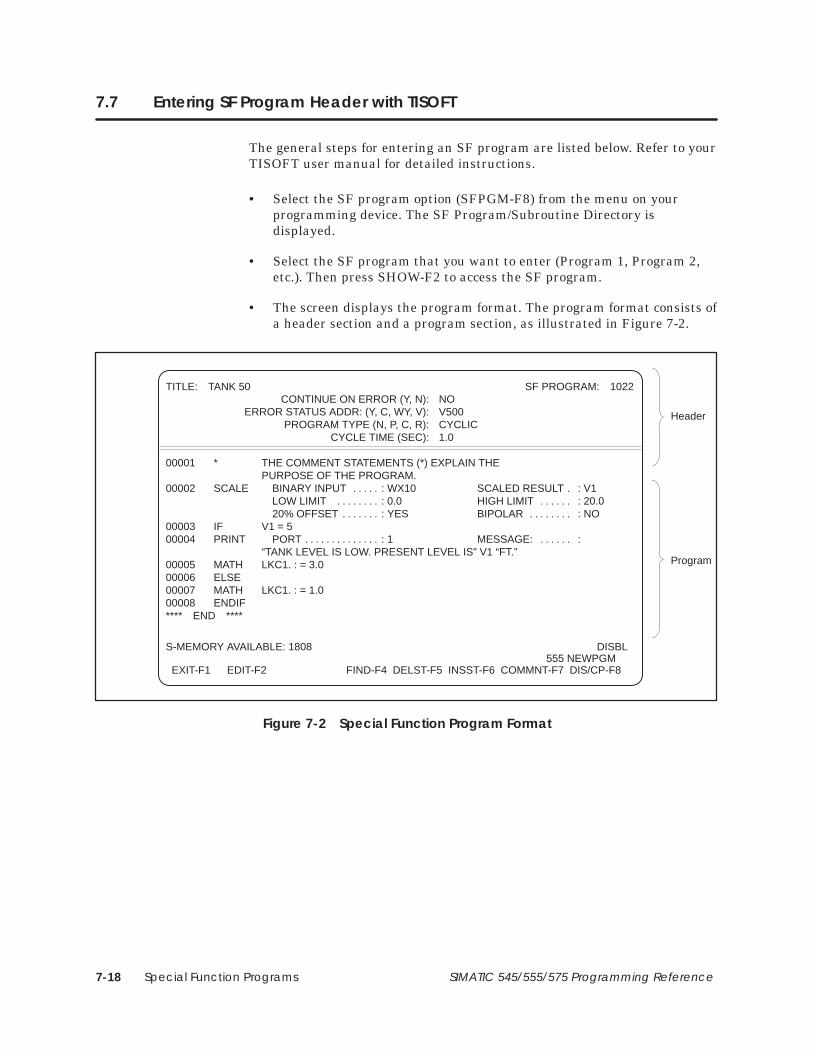
Special Function Programs7-18 SIMATIC 545/555/575 Programming Reference
7.7 Entering SF Program Header with TISOFT
The general steps for entering an SF program are listed below. Refer to yourTISOFT user manual for detailed instructions.
• Select the SF program option (SFPGM-F8) from the menu on yourprogramming device. The SF Program/Subroutine Directory isdisplayed.
• Select the SF program that you want to enter (Program 1, Program 2,etc.). Then press SHOW-F2 to access the SF program.
• The screen displays the program format. The program format consists ofa header section and a program section, as illustrated in Figure 7-2.
TITLE: TANK 50 SF PROGRAM: 1022CONTINUE ON ERROR (Y, N): NO
ERROR STATUS ADDR: (Y, C, WY, V): V500PROGRAM TYPE (N, P, C, R): CYCLIC
CYCLE TIME (SEC): 1.0
00001 * THE COMMENT STATEMENTS (*) EXPLAIN THE PURPOSE OF THE PROGRAM.
00002 SCALE BINARY INPUT : WX10 SCALED RESULT : V1 . . . . . . LOW LIMIT : 0.0 HIGH LIMIT : 20.0 . . . . . . . . . . . . . . 20% OFFSET : YES BIPOLAR : NO. . . . . . . . . . . . . . .
00003 IF V1 = 500004 PRINT PORT : 1 MESSAGE: :. . . . . . . . . . . . . . . . . . . .
“TANK LEVEL IS LOW. PRESENT LEVEL IS” V1 “FT.”00005 MATH LKC1. : = 3.000006 ELSE00007 MATH LKC1. : = 1.000008 ENDIF**** END ****
S-MEMORY AVAILABLE: 1808 DISBL555 NEWPGM
EXIT-F1 EDIT-F2 FIND-F4 DELST-F5 INSST-F6 COMMNT-F7 DIS/CP-F8
Header
Program
Figure 7-2 Special Function Program Format

Special Function Programs 7-19SIMATIC 545/555/575 Programming Reference
• Press EDIT-F2 to enter SF program edit mode.
• Enter a title for the program. The title is optional and can be left blank.
• The CONTINUE ON ERROR field specifies if the program is to continueto run when an error occurs. Enter Y in this field to have the programcontinue when an error occurs. Enter N in this field to have programstop when an error occurs. See Section 7.8 for a discussion of errorreports.
• The ERROR STATUS ADDRESS field specifies how error conditions arehandled. In order to have an error code written when a program erroroccurs, you must specify a V-Memory location or a word output (WY) inthis field. If you enter a control relay or discrete output point in thisfield, then this point is set when an error occurs. Refer to Section 7.8 fora discussion of error reports.
• The PROGRAM TYPE field specifies the program type. Enter N for anon-priority program, P for a priority program, C for a cyclic program, orR for a restricted program. Refer to Section 7.1 for a discussion ofSF program types.
• The CYCLE TIME field sets the periodicity of the program execution.For a cyclic program, enter the cycle time in seconds (0.5–6553.5). Forexample, a program with a cycle time of 5 seconds is executed every fiveseconds. Note that the controller rounds the value that you enter up tothe next 0.5 second interval.
• Save the header information, and then proceed to the program section.

Special Function Programs7-20 SIMATIC 545/555/575 Programming Reference
7.8 Reporting SF Program or SFSUB RLL Instruction Errors
When you enter an SF program or an SFSUB RLL instruction, you have theoption of specifying how to report errors. You assign an address in theERROR STATUS ADDRESS field of the SF program header, (described inSection 7.7) or in the ER field of the SFSUB RLL instruction (described inSection 6.50). In this field, you can specify a control relay (C), a discreteoutput (Y), a V-Memory location, or a word output (WY).
The Special Function Error Code (SFEC) variable may be used to read fromor write to the error code for an SF program or for an SFSUB RLLinstruction. Each SF program or SFSUB RLL instruction contains oneSFEC variable. All references to SFEC within an SF program or an SFSUBRLL instruction’s parameters, or within any SF subroutine called by the SFprogram or SFSUB RLL instruction, refers to this single SFEC variable.(The programming system may require that you specify a number when youenter the SFEC variable name, e.g., SFEC1. The programmable controllerignores this number.)
When an SF program or an SFSUB RLL instruction is queued for execution,the SFEC for that SF program or SFSUB RLL instruction is cleared to zero.If an error occurs during execution, the error code associated with the error(refer to Appendix F) is written to SFEC. Errors can be detected by theoperating system or they can be detected by the user program. If an error isdetected by the user program, you indicate it to the system by anassignment to SFEC in a MATH or IMATH statement.
If you select NO in the CONTINUE ON ERROR field when you enter an SFProgram, or, if you select STOP ON ERROR when you enter an SFSUB RLLinstruction, assigning a non-zero value to the SFEC variable causes the SFprogram or SFSUB RLL instruction to terminate. (You can forcetermination of the SF program or SFSUB instruction by having yourprogram or subroutine assign a non-zero value to SFEC.)
If you select YES in the CONTINUE ON ERROR field when you enter anSF Program, or CONTINUE ON ERROR when you enter an SFSUB RLLinstruction, writing to the SFEC variable does not cause the SF program orSFSUB RLL instruction to terminate. In this case, your SF program or SFsubroutine can examine the SFEC variable and take corrective active, asapplicable. However, you are not able to force termination by writing toSFEC.
If you specify a control relay (C) or discrete output (Y) in the ERRORSTATUS ADDRESS field when you enter an SF program, or in the ER fieldwhen you enter an SFSUB RLL instruction, this discrete point is set to oneif an error occurs. No other report of the error is made; no error code iswritten.
Reporting Errorswith the SFECVariable
Reporting Errorswith Discrete Points

Special Function Programs 7-21SIMATIC 545/555/575 Programming Reference
If you specify a V-Memory location (Vn) or word output (WYn) in theERROR STATUS ADDRESS field when you enter an SF program, or in theER field when you enter an SFSUB RLL instruction, then three words ofmemory are reserved, as shown in Figure 7-3.
V or WYn
n+1
n+2
Bit
1 2 3 4 5 6 7 8 9 10 11 12 13 14 15 16
0 Error Code
Control Block ID
Statement Number
Figure 7-3 Word Specification for SF Program Errors
The error code is contained in the low-order eight bits of the first word(word n) in the group. Appendix F lists the error codes and their definitions.
The second word in the group (word n+1) is the control block ID. Thecontroller assigns a control block for each loop, analog alarm, SF programand SF subroutine. The header in each control block stores information inthe following format.
• Bits 1 and 2 (in word n+1) always contain zero.
• The next four bits (bits 3–6 in word n+1) indicate the control block typeas follows.
0000: Loop Control Block
0001: Analog Alarm Control Block
0010: SF program Control Block
0011: SF subroutine Control Block or SFSUB RLL Instruction
0100 through 1111 are not used
• The next 10 bits (bits 7–16 in word n+1) are allocated for the ControlBlock Number or SFSUB RLL Instruction number.
The third word in the group (word n+2) contains the statement number ofeither the last SF statement to be executed correctly, or the statementnumber of the statement executing when the error occurred. (The ControlBlock ID indicates the SF program or SF subroutine that contains thestatement.)
Reporting Errorswith V or WYMemory

Special Function Programs7-22 SIMATIC 545/555/575 Programming Reference
7.9 Entering Special Function Programming Statements
Each SF statement has one or more fields in which you enter data when youuse the statement in an SF program. For each field, you enter a field typeand a field descriptor, which are defined in Table 7-3.
Table 7-3 SF Statement Field Entry Definitions
Field Type
Element
Elements are comprised of a data type and a number. A period following theelement designates the element as an address of a real number. No perioddesignates the element as an address of an integer. Examples of elementsare: V100 or V100. or LPVH1. or C102, etc.
Address
AddressExpression
An address expression is a logical group of tokens evaluating to an address,where a token is the smallest indivisible unit, e.g., an element, operator,constant, parenthesis, etc. PowerMath CPUs also support 16-bit unsignedintegers (identified with a U suffix, e.g., V105U) and 32-bit signed integers(identified with an L suffix, e.g., K15L) Examples of address expressions are
V100(3) evaluates to the address V102
V100.(2) evaluates to the address V101.
V102.(:T16 + 10:) if T16 = 2, evaluates to the address V124.
V105U, K15L (PowerMath CPUs only)
LiteralConstant
A literal constant is a real or integer number, such as 78, 3.468, 32980, etc.
ValueValueExpression
A value expression is a logical group of tokens evaluating to a value, where atoken is the smallest indivisible unit, e.g., an element, operator, constant,parenthesis, etc. Examples of value expressions are
V100:= LKD2.**3
(V100 + K774)
(V102(3))
32768U (PowerMath CPUs only)
600L (PowerMath CPUs only)
Field Descriptor
Integer onlyThis field only accepts an integer value (e.g., 3761 or (V11 + 7)) or an address containing aninteger value (e.g., V100 or WX88 or V100(2); PowerMath CPUs also support unsigned 16-bitintegers and signed 32-bit integers (e.g., V105U, K15L).
Real only This field only accepts a real value (e.g., 33.421) or an address containing a real value,(e.g., V121. or V888. (13)).
Integer/Real This field accepts a real or integer value or an address containing a real or integer value.
Writeable This field only accepts a writeable address, (e.g., WY1000 or V23. or C55). Read-onlyaddresses, (e.g., K551 or WX511 or X69) are not allowed.
Optional An entry in this field is optional and the field can be left blank.
Bit This field only accepts an address that contains a bit value (e.g., X17 or C200 or Y91).
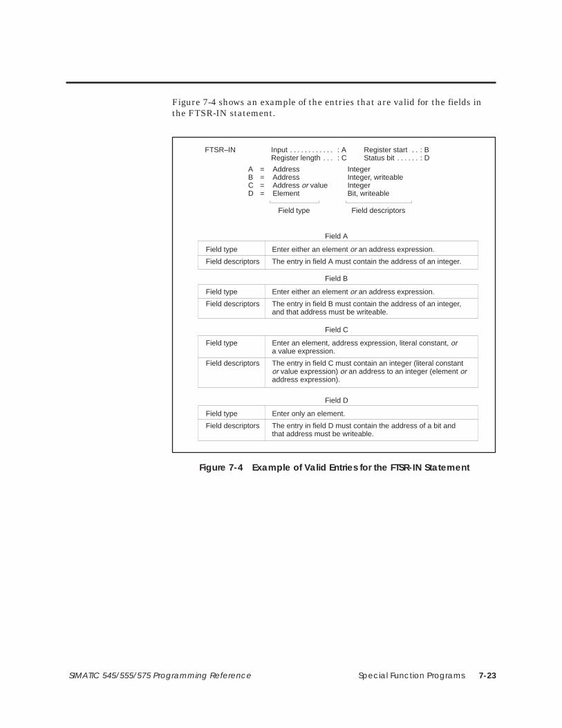
Special Function Programs 7-23SIMATIC 545/555/575 Programming Reference
Figure 7-4 shows an example of the entries that are valid for the fields inthe FTSR-IN statement.
Field type Field descriptors
Field A
Field type Enter either an element or an address expression.
Field descriptors The entry in field A must contain the address of an integer.
Field B
Field type Enter either an element or an address expression.
Field descriptors The entry in field B must contain the address of an integer,and that address must be writeable.
A = Address IntegerB = Address Integer, writeableC = Address or value IntegerD = Element Bit, writeable
FTSR–IN Input : A Register start : B. . . . . . . . . . . . . . Register length : C Status bit : D. . . . . . . . .
Field C
Field type Enter an element, address expression, literal constant, ora value expression.
Field descriptors The entry in field C must contain an integer (literal constantor value expression) or an address to an integer (element oraddress expression).
Field D
Field type Enter only an element.
Field descriptors The entry in field D must contain the address of a bit and that address must be writeable.
Figure 7-4 Example of Valid Entries for the FTSR-IN Statement

Special Function Programs7-24 SIMATIC 545/555/575 Programming Reference
7.10 Convert BCD to Binary
The Convert BCD to Binary statement converts binary coded decimal (BCD)inputs to a binary representation of the equivalent integer. The BCDBINformat is shown in Figure 7-5.
BCDBIN BCD input : A Binary result : B. . . . .
A = Address IntegerB = Address Integer, writeable
Figure 7-5 BCDBIN Format
• A is the memory location of the BCD word to be converted.
• B is the memory location of the integer value after conversion.
The operation of BCDBIN is described below and illustrated in Figure 7-6.
• Each time the BCDBIN statement executes, the four digits of the BCDvalue located in the address specified by A are converted to the binaryrepresentation of the equivalent integer value.
• The result is stored in the address specified by B.
BCDBIN BCD Input: WX01 Binary result: WY11
0 1 0 0 0 0 10 1 0 0 1 0 0 11
0 0 0 1 0 0 00 0 1 1 0 0 0 10
4 1 9 3
WX01 contains BCD value 4193entered from a thumbwheel
WY11 contains binaryrepresentation of integer 4193
A: WX01 B: WY11
Figure 7-6 Example of BCDBIN Operation
BCDBIN
BCDBIN Description
BCDBIN Operation

Special Function Programs 7-25SIMATIC 545/555/575 Programming Reference
7.11 Convert Binary Inputs to BCD
The Convert Binary Inputs to BCD statement (Figure 7-7) converts thebinary representation of an integer to the equivalent Binary Coded Decimal(BCD) value. Values up to 9999 are converted to equivalent BCD values.
BINBCD Binary input : A BCD result : B. . . . .
A = Address IntegerB = Address Integer, writeable
Figure 7-7 BINBCD Format
• A is the memory location of the integer to be converted.
• B is the memory location of the BCD word after conversion.
The operation of BINBCD is described below and illustrated in Figure 7-8.
• Each time the BINBCD statement executes, the integer located in theaddress specified by A is converted to BCD.
• An error occurs if the input value contained in A is less than zero orgreater than 9999.
• The BCD value is stored in the address specified by B.
A: V77
0 0 0 0 0 0 01 1 1 0 1 0 0 01
B: WY11
0 0 0 1 0 1 00 0 0 1 1 0 1 00
1 2 3 4
BINBCD Binary input: V77 BCD result: WY11
V77 contains binaryrepresentation of integer 1234
WY11 contains BCD 1234
Figure 7-8 Example of BINBCD Operation
BINBCD Description
BINBCD Operation
BINBCD
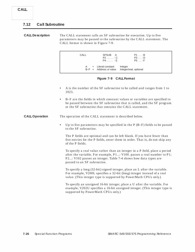
Special Function Programs7-26 SIMATIC 545/555/575 Programming Reference
7.12 Call Subroutine
The CALL statement calls an SF subroutine for execution. Up to fiveparameters may be passed to the subroutine by the CALL statement. TheCALL format is shown in Figure 7-9.
CALL SFSUB A P1 : B. . P2 : C P3 : D. . . . . . . P4 : E P5 : F. . . . . . .
A = Literal constant IntegerB–F = Address or value Integer/real, optional
Figure 7-9 CALL Format
• A is the number of the SF subroutine to be called and ranges from 1 to1023.
• B–F are the fields in which constant values or variables are specified tobe passed between the SF subroutine that is called, and the SF programor the SF subroutine that contains the CALL statement.
The operation of the CALL statement is described below.
• Up to five parameters may be specified in the P (B–F) fields to be passedto the SF subroutine.
The P fields are optional and can be left blank. If you have fewer thanfive entries for the P fields, enter them in order. That is, do not skip anyof the P fields.
To specify a real value rather than an integer in a P field, place a periodafter the variable. For example, P1...: V100. passes a real number to P1;P2...: V102 passes an integer. Table 7-4 shows how data types arepassed to an SF subroutine.
To specify a long (32-bit) signed integer, place an L after the variable.For example, V200L specifies a 32-bit (long) integer instead of a realvalue. (This integer type is supported by PowerMath CPUs only.)
To specify an unsigned 16-bit integer, place a U after the variable. Forexample, V202U specifies a 16-bit unsigned integer. (This integer type issupported by PowerMath CPUs only.)
CALL
CALL Description
CALL Operation

Special Function Programs 7-27SIMATIC 545/555/575 Programming Reference
• When the CALL statement executes, the following actions occur:
Control is transferred to the specified SF subroutine. Any parametersspecified in the P fields are read by the SF subroutine.
Statements within the SF subroutine execute, and parameters in the Pfields that are modified by the SF subroutine are updated. Then controltransfers back to the SF program that called the SF subroutine.
Table 7-4 Specifying Real or Integer Parameters
Data Type Specified inCALL Statement
Data Type Specified inSF Subroutine*
P Data Type Used inSF subroutine*
real ( real ( real (
real ( integer real (
integer real ( real (
integer integer integer
*See Section 7.5 for more information about specifying data types in SF subroutines.
! CAUTIONSubroutines may be nested to four levels. If the limit of four levels is exceeded,an error results.
This causes termination of the SF program and all subroutines prior to the onethat exceeded the level.
CONTINUE ON ERROR does not override this condition. Ensure that you do notnest subroutines for more than four levels.
CALL

Special Function Programs7-28 SIMATIC 545/555/575 Programming Reference
7.13 Correlated Data Table
The Correlated Data Table statement compares an input value (the input)to a table of values (the input table), and locates a value in the input tablethat is greater than or equal to the input. The CDT then writes the valuelocated in a second table (the output table), that is correlated with the valuelocated in the input table, to an output address (the output). The CDTformat is shown in Figure 7-10.
CDT Input : A Output : B. . . . . . . . . . . . . . . . Input table : C Output table : D. . . . . . Table length : E.
A = Address Integer/realB = Address Integer/real, writeableC = Address Integer/realD = Address Integer/realE = Address or value Integer
Figure 7-10 CDT Format
• A is the input address.
• B is the address to which the output value is written.
• C is the starting address for the input table. When used in a compiledSF program or subroutine, you must specify a static table; that is, thetable’s base address must be a V, K, G, VMS, or VMM address.
• D is the starting address for the output table. When used in a compiledSF program or subroutine, you must specify a static table; that is, thetable’s base address must be a V, K, G, VMS, or VMM address.
• E is the length of each table and must be a value greater than zero.When used in a compiled SF program or subroutine, the table lengthmust be specified as a value.
CDT
CDT Description

Special Function Programs 7-29SIMATIC 545/555/575 Programming Reference
CDT statement operation is described here and illustrated in Figure 7-11.
• When the CDT is executed, the CDT compares the value of an inputelement specified in A to a pre-existing table of values having a startingaddress specified in C. The first value in the input table that is greaterthan or equal to the input is located.
• A value in a second pre-existing table (starting address specified in D)that correlates with the selected value in the input table is written to anoutput address specified in B.
• The input table must be in ascending order. That is, the lowest value islocated in the lowest memory location and the highest value is located inthe highest memory location.
• Table length E depends upon the memory location that you choose, andhow much memory you allocated if the memory is user configurable.
• Both tables must have the same number of entries.
Input table Output tableK64 = 20 K84 = 48K65 = 28 K85 = 23K66 = 34 K86 = 62K67 = 39 K87 = 98
(Input value) V1=40 K68 = 43 K88 = 72 (Output value) V2=72K69 = 47 K89 = 65K70 = 50 K90 = 41
CDT Input : V1 Output : V2. . . . . . . . . . . . . . . Input table : K64 Output table : K84. . . Table length : 7.
Figure 7-11 CDT Statement Example
The input address V1 contains the value 40. The value in the input tablethat is greater than or equal to 40 is 43, contained in K68. The correlatedvalue in the output table is in K88. The value written to the output addressV2 is 72.
CDT Operation
CDT

Special Function Programs7-30 SIMATIC 545/555/575 Programming Reference
7.14 Exit on Error
The EXIT statement allows you to terminate an SF program orSF subroutine and have an error code logged. The EXIT format is shown inFigure 7-12.
EXIT Errcode : A. .
A = Literal constant Integer, optional
Figure 7-12 EXIT Format
• A contains the value of the error code and can range from 0 to 255.
The operation of the EXIT statement is described below.
• When the SF program encounters the EXIT statement, programexecution terminates. If an SF subroutine encounters the EXITstatement, the subroutine and calling SF program are terminated.
• If you use the EXIT statement in conjunction with an IF statement, youcan terminate the program under specific conditions.
You can leave A blank and the current error code is written to theERROR STATUS ADDRESS that you specify in the SF program header.If this address is a discrete point, it turns on.
You can define an error condition and assign it an error code 200–255(codes 0–199 are reserved). When the EXIT statement executes, theprogram terminates and this error code is written to the ERRORSTATUS ADDRESS. If this address is a discrete point, it turns on.
EXIT
EXIT Description
EXIT Operation
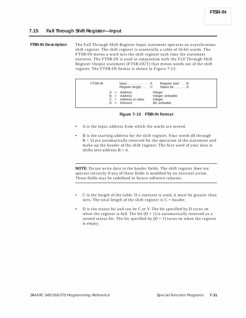
Special Function Programs 7-31SIMATIC 545/555/575 Programming Reference
7.15 Fall Through Shift Register—Input
The Fall Through Shift Register Input statement operates an asynchronousshift register. The shift register is essentially a table of 16-bit words. TheFTSR-IN moves a word into the shift register each time the statementexecutes. The FTSR-IN is used in conjunction with the Fall Through ShiftRegister Output statement (FTSR-OUT) that moves words out of the shiftregister. The FTSR-IN format is shown in Figure 7-13.
A = Address IntegerB = Address Integer, writeableC = Address or value IntegerD = Element Bit, writeable
FTSR-IN Input : A Register start : B. . . . . . . . . . . . . . Register length : C Status bit : D. . . . . . . . .
Figure 7-13 FTSR-IN Format
• A is the input address from which the words are moved.
• B is the starting address for the shift register. Four words (B throughB + 3) are automatically reserved for the operation of the statement andmake up the header of the shift register. The first word of your data isshifts into address B + 4.
NOTE: Do not write data to the header fields. The shift register does notoperate correctly if any of these fields is modified by an external action.These fields may be redefined in future software releases.
• C is the length of the table. If a constant is used, it must be greater thanzero. The total length of the shift register is C + header.
• D is the status bit and can be C or Y. The bit specified by D turns onwhen the register is full. The bit (D + 1) is automatically reserved as asecond status bit. The bit specified by (D + 1) turns on when the registeris empty.
FTSR-IN Description
FTSR-IN

Special Function Programs7-32 SIMATIC 545/555/575 Programming Reference
Fall Through Shift Register—Input (continued)
The operation of the FTSR-IN statement is described below.
• FTSR-IN is used in conjunction with an FTSR-OUT; you must use thesame corresponding values for register start, register length, and statusbit in the two FTSR statements.
• A is the input address from which the words are moved into the shiftregister.
• The starting address B determines the memory area in which the shiftregister is located. The first word of your data shifts into address B + 4.
• The four words (B through B + 3) are automatically reserved for theoperation of the shift register.
(B) contains the Count, which equals the current number of entries inthe shift register.
(B + 1) contains the Index, which acts like a pointer to indicate the nextavailable location of the shift register into which a word can be shifted.When the Index equals zero, the next available location is (B + 4); whenthe Index equals one, the next available location is (B + 5), and so on.
(B + 2) contains the Length, which equals the maximum size of the shiftregister in words.
(B + 3) contains the Checkword. The checkword is used internally toindicate whether the FTSR is initialized.
• The register length C determines the size of the shift register. Theregister length depends upon the memory location that you choose andhow much memory you have allocated (if the memory isuser-configurable).
• The status bit specified by D is turned on to indicate that the register isfull. The bit (D + 1) is automatically reserved as a second status bit andturns on whenever the shift register is empty.
Use the same status bits for the FTSR-IN that you use for theFTSR-OUT. FTSR-IN sets D when the register fills. FTSR-OUT clearsthis bit as the function executes. FTSR-OUT sets (D + 1) when theregister is empty. FTSR-IN clears this bit.
FTSR-IN
FTSR-IN Operation

Special Function Programs 7-33SIMATIC 545/555/575 Programming Reference
• If the shift register is empty, status bit D is off and (D + 1) is on.
• When the FTSR-IN executes, the following actions occur.
The word currently in memory location A is shifted into the locationspecified by the Index.
The Count and the Index are each incremented by one.
Status bit (D + 1) turns off.
• Each time the FTSR-IN executes, another word moves into the nextavailable location; the Index and the Count increment by one. When theIndex equals the length, it resets to zero after the next execution by theFTSR-IN.
• When the shift register is full, another word cannot be shifted in untilone is shifted out by the FTSR-OUT statement.
• When the shift register is full, status bit D turns on. If you attempt toshift in another word, an error generates. (Appendix F, error 87).
• You can use FTSR-OUT to remove words from the shift register beforeall locations are full. You can use FTSR-IN to shift more words into theshift register before all words are removed.
Figure 7-14 illustrates the operation of the FTSR-IN statement.
FTSR-IN

Special Function Programs7-34 SIMATIC 545/555/575 Programming Reference
Fall Through Shift Register—Input (continued)
Input word in V100
Index pointsto location 0
V196
V197
V198
V199
V200
V201
V202
Count = 0Index = 0Length = 3
Checkword
• The Count (V196) contains 0 because the shift register is empty.• The Index (V197) contains 0 because the next available location is
number 0 (V200).• The Register Full Status Bit (C99) is off. The Register Empty
Status Bit (C100) is on.
1 This status is set automatically by the controller the first time thatthe FTSR is executed.
9137
Input word in V100
V196
V197
V198
V199
V200
V201
V202
Count = 1Index = 1Length = 3
Checkword
• The input address V100 contains the value 9137.• The Count (V196) contains 1 because one location is filled.• The Index (V197) contains 1 because the next available location is
number 1 (V201).• The shift register location V200 contains the value 9137.• The Register Full Status Bit (C99) is off. The Register Empty
Status Bit (C100) is off.
3391
Input word in V100
V196
V197
V198
V199
V200
V201
V202
Count = 2Index = 2Length = 3
Checkword
9137
33919137
• The input address V100 contains the value 3391.• The Count (V196) contains 2 because two locations are filled.• The Index (V197) contains 2 because the next available location
is number 2 (V202).• The shift register location V201 contains the value 3391.• The Register Full Status Bit (C99) is off. The Register Empty
Status Bit (C100) is off.
7992
33919137
Input word in V100
V196
V197
V198
V199
V200
V201
V202
Count = 3Index = 0Length = 3
Checkword
• The input address V100 contains the value 7992.• The Count (V196) contains 3 because three locations are filled.• The Index (V197) contains 0 because the next available location
is number 0 (V200) after the word currently in V200 isremoved.
• The shift register location V202 contains the value 7992.• The Register Full Status Bit (C99) is on. The Register Empty
Status Bit (C100) is off. 7992
Shift register status before first word is moved in1
Shift register status after first word is moved in
Shift register status after second word is moved in
Shift register status after third word is moved in
FTSR-IN Input :V100 Register start :V196. . . . . . . . . . . . . . Register length :3 Status bit : C99. . . . . . . . .
Index pointsto location 1
Index pointsto location 2
Index pointsto location 3
Figure 7-14 Example of FTSR-IN Operation
FTSR-IN

Special Function Programs 7-35SIMATIC 545/555/575 Programming Reference
7.16 Fall through Shift Register—Output
The Fall Through Shift Register Output statement operates anasynchronous shift register. The shift register is essentially a table of 16-bitwords. The FTSR-OUT moves data out of the shift register each time thestatement executes. The FTSR-OUT is used in conjunction with the FallThrough Shift Register Input statement (FTSR-IN) that moves words intothe shift register. Figure 7-15 shows the FTSR-OUT format.
A = Address Integer, writeableB = Address Integer, writeableC = Address or value IntegerD = Element Bit, writeable
FTSR-OUT Register start : A Output : B. . . . . . Register length : C Status bit : D. . .
Figure 7-15 FTSR-OUT Format
• A is the starting address for the shift register. The four words(A through A + 3) are automatically reserved for the operation of thestatement and make up the header of the shift register.
NOTE: Do not write data to the header fields. The shift register does notoperate correctly if any of these fields is modified by an external action.These fields may be redefined in future software releases.
• B is the output address to which the words are moved.
• C is the length of the table. If a constant is used, it must be greaterthan 0.
• D is the status bit and can be C or Y. The bit specified by D is turned onwhen the register is full. The bit (D + 1) is automatically reserved as asecond status bit. The bit specified by (D + 1) is turned on when theregister is empty.
FTSR-OUTDescription
FTSR-OUT

Special Function Programs7-36 SIMATIC 545/555/575 Programming Reference
Fall Through Shift Register—Output (continued)
The operation of the FTSR-OUT statement is described below.
• FTSR-OUT is used in conjunction with a FTSR-IN; you must use thesame corresponding values for register start, register length, and statusbit in the two FTSR statements.
• Starting address A determines the memory area in which the shiftregister is located. The first word of user data is located in addressA + 4.
• The four words (A through A + 3) are automatically reserved for theoperation of the shift register.
(A) contains the Count, which equals the current number of entries inthe shift register.
(A + 1) contains the Index, which acts like a pointer to indicate the nextavailable location of the shift register into which a word can be shifted.When the Index equals zero, the next available location is (A + 4); whenthe Index equals one, the next available location is (A + 5), and so on.
(A + 2) contains the Length, which equals the maximum size of the shiftregister in words.
(A + 3) contains the Checkword. The checkword is used internally toindicate whether the FTSR has been initialized.
• B is the output address into which the words are moved.
• The register length C determines the size of the shift register. Theregister length depends upon the memory location that you choose andhow much memory you allocated (if the memory is user configurable).
• D is the status bit and can be C or Y. The bit specified by D turns on toindicate that the register is full. The bit (D + 1) is automaticallyreserved as a second status bit and turns on whenever the shift registeris empty.
Use the same status bits for the FTSR-OUT that you use for theFTSR-IN. FTSR-IN sets D when the register is full. FTSR-OUT clearsthis bit as the function executes. FTSR-OUT sets (D + 1) when theregister is empty. FTSR-IN clears this bit.
FTSR-OUT
FTSR-OUTOperation

Special Function Programs 7-37SIMATIC 545/555/575 Programming Reference
• If the shift register contains one or more words, the Count equals thenumber of current entries. The Index points to the next availablelocation of the shift register into which a word can be moved. Status bit(D + 1) is off. Status bit D is on if the shift register is full.
• When the FTSR-OUT executes, the following actions occur.
The oldest word in the shift register shifts into memory location B.
The Count decrements by one.
The Index is unchanged and continues to point to the next availablelocation into which a word can be moved.
• Each time the FTSR-OUT executes, another word moves out of the shiftregister and the Count is decremented by one. The Index remainsunchanged.
• After the shift register is empty, the Index and Count contain zero.Status bit D turns off and status bit (D + 1) turns on. If you attempt toshift a word out of an empty shift register, an error is generated(Appendix F, error 86).
• You can use FTSR-OUT to remove words from the shift register beforeall locations are full. You can use FTSR-IN to shift more words into theshift register before all words are removed.
Figure 7-16 illustrates the operation of the FTSR-OUT statement.
FTSR-OUT

Special Function Programs7-38 SIMATIC 545/555/575 Programming Reference
Fall Through Shift Register—Output (continued)
• The Count (V196) contains 3 because three locations are filled.
• The Index (V197) contains 0 because the next availablelocation for a word to be moved in is number 0 (V200).
• The Register Full Status Bit (C99) is on.The Register Empty Status Bit (C100) is off.
1 This status is set automatically by the controller the first time thatthe FTSR is executed.
• The output address V300 contains the value 9137.• The Count (V196) contains 2 because two locations
are filled.• The Index (V197) contains 0 because the next
available location for a word to be moved in is number 0 (V200).
• The Register Full Status Bit (C99) is off.The Register Empty Status Bit (C100) is off.
• The output address V300 contains the value 3391.• The Count (V196) contains 1 because one location
is filled.• The Index (V197) contains 0 because the next
available location for a word to be moved in isnumber 0 (V200).
• The Register Full Status Bit (C99) is off.The Register Empty Status Bit (C100) is off.
• The output address V300 contains the value 7992.• The Count (V196) contains 0 because the shift
register is empty.• The Index (V197) contains 0 because the next
available location for a word to be moved in isnumber 0 (V200).
• The Register Full Status Bit (C99) is off.The Register Empty Status Bit (C100) is on.
Shift register status before first word Is moved out1
Shift register status after first word is moved out
Shift register status after second word is moved out
Shift register status after third word is moved out
Index pointsto location 0
V196
V197
V198
V199
V200
V201
V202
Count = 3Index = 0
CheckwordLength = 3
Output word in V300
33919137
7992
33919137
7992
V196
V197
V198
V199
V200
V201
V202
Count = 2Index = 0Length = 3
Checkword
9137
33919137
7992
3391
V196
V197
V198
V199
V200
V201
V202
Count = 1Index = 0Length = 3
Checkword
A location in the shift register is not cleared when a word is moved out. The Count determines how many words remain in theshift register.
33919137
7992
7992
V196
V197
V198
V199
V200
V201
V202
Count = 0Index = 0Length = 3
Checkword
FTSR-OUT Register start :V196 Output :V300. . . . . . Register length :3 Status bit :C99. . .
Index pointsto location 0
Output word in V300
Index pointsto location 0
Output word in V300
Index pointsto location 0
Output word in V300
Figure 7-16 Example Of FTSR-OUT Operation
FTSR-OUT

Special Function Programs 7-39SIMATIC 545/555/575 Programming Reference
7.17 Go To/Label Function
The GOTO statement continues program execution at a specified LABELstatement. The GOTO and the LABEL statements are always used together.The format of the two statements is shown in Figure 7-17.
A = Literal constant Integer
GOTO LABEL : A. . . . .
<SF Statement><SF Statement><SF Statement>
LABEL LABEL : A. . . . .
Figure 7-17 GOTO/LABEL Format
• The <SF statement> may be any of the SF program statements.
• A is the label and can range from 0 to 65535.
When the SF program encounters the GOTO, program execution continuesat the LABEL specified by A.
Figure 7-18 illustrates the use of the GOTO/LABEL statement.
00005 MATH V100 := V500
00006 IF V100 < 1000
00007 GOTO LABEL 37415
00008 ELSE
00009 GOTO LABEL 38000
00010 ENDIF
00011 LABEL LABEL 37415
00012 MATH V100 := V465/K99
Figure 7-18 Example of GOTO/LABEL Statements
! CAUTIONDo not repeat label definitions or leave a label undefined.
To do so may cause the controller to enter the F ATAL ERROR mode, freezeanalog outputs and turn off discrete outputs.
Ensure that all labels have a unique definition.
GOTO

Special Function Programs7-40 SIMATIC 545/555/575 Programming Reference
7.18 IF/IIF/THEN/ELSE Functions
The IF or IIF (Integer IF) statement is used for the conditional execution ofstatements and operates in conjunction with the ELSE and the ENDIFstatements. When an IF statement is used, a THEN result is understood.The IF format is shown in Figure 7-19.
NOTE: Integer IF operations are available only in CPUs that supportPowerMath.
IF (IIF) Free format based on the following structure:
IF <valid MATH (or IMATH) expression> <THEN understood> . . <SF statement><SF statement>...<SF statement>
ELSE<SF statement><SF statement>...<SF statement>
ENDIF(The <SF statement> may be anyof the SF program statements.)
Figure 7-19 IF Format
! CAUTIONDo not use an IF (or IIF) without an ENDIF .
To do so may cause the controller to enter the F ATAL ERROR mode, freezeanalog outputs and turn off discrete outputs.
Ensure that all IF statements are completed with an ENDIF statement.
Figure 7-20 illustrates the operation of the IF (or IIF) statement describedbelow.
• Each time the IF executes, the condition defined within the statement istested.
• If the <expression> is true (non-zero), statements in the THEN sectionexecute; any statements in the ELSE section are skipped.
• If the <expression> is false (zero), statements in the THEN section areskipped; any statements in the ELSE section execute.
IF/IIF
IF/THEN/ELSEDescription
IF Operation

Special Function Programs 7-41SIMATIC 545/555/575 Programming Reference
• The <expression> can be any MATH expression in IF statements orIMATH expresion in IIF statements. See Table 7-7 for a list of theMATH functions. The use of the assignment operator ( := ) in anexpression is optional.
• The IF statement operates in conjunction with the ENDIF statementand an optional ELSE statement.
• IIF (Integer IF) allows you to code IF-THEN-ELSE blocks using aninteger-only expression for the conditional. An integer expressionexecutes faster than the equivalent floating-point expression.
• The ENDIF indicates the end of an IF-THEN-ELSE structure.
• If there is no ELSE statement, the statements between the IF and theENDIF are treated as THEN statements.
• If an ELSE statement is used, then any statements between IF andELSE constitute by default a THEN section. An ELSE statementindicates the end of the THEN section and the beginning of the ELSEsection in an IF-THEN-ELSE structure.
• Statements between ELSE and ENDIF constitute the ELSE section inthe IF statement.
• IF, ELSE and ENDIF statements may be nested to any level.
0003 IF V1. >= 5.35 AND V1. <= 7.65
0004 PRINT PORT.....:1 MESSAGE.....:“TANK LEVEL IS LOW. PRESENT LEVEL IS”
V1 “FT.”
0005 MATH LKC1. := 3.00
0006 ELSE
0007 MATH LKC1. := 1.00
0008 ENDIF
0009 IIF V1 = 5
0010 PRINT PORT.....:1 MESSAGE.....:“TANK LEVEL IS LOW. PRESENT LEVEL IS”
V1 “FT.”
0011 MATH LKC1. := 3.00
0012 ELSE
0013 MATH LKC1. := 1.00
0014 ENDIF
Figure 7-20 Example of IF/THEN/ELSE Statements
IF/IIF

Special Function Programs7-42 SIMATIC 545/555/575 Programming Reference
7.19 Integer Math Operations
The Integer Math statement executes integer arithmetic computations. TheIMATH format, based on the functions in Table 7-5, is shown in Figure 7-21.
NOTE: Non-PowerMath CPUs do not support the following operators: = <> < <= > >=, AND, OR, and the ABS intrinsic function.
Table 7-5 IMATH Operators
Operator Description
NOT Unary Not—The expression “NOT X” returns the one’s complement of X.
> > Shift right (arithmetic)1
< < Shift left (arithmetic)1
* Multiplication
/ Integer division— Any remainder left over after the division is truncated.
MOD Modulo arithmetic—The expression “X mod Y” returns the remainder of X afterdivision by Y.
+ Addition
– Subtraction/unary minus (negation)
= Equal. The expression X = Y returns 1 if X equals Y, and zero if not.2
<> Not equal. The expression X <> Y returns 1 if X is not equal to Y, and zero if so.2
< Less than. The expression X < Y returns 1 if X is less than Y, and zerootherwise.2
<= Less Than or Equal. The expression X <= Y returns 1 if X is less than or equal toY, and zero otherwise.2
> Greater Than. The expression X > Y returns 1 if X is greater than Y, and zerootherwise.2
>= Greater Than or Equal. The expression X >= Y returns 1 if X is greater than orequal to Y, and zero otherwise.2
AND Logical AND. The expression X AND Y returns 1 if both X and Y are non-zero,and zero otherwise.2
OR Logical OR. The expression X OR Y returns 1 if either X or Y is non-zero, andzero otherwise.2
& Bit-by-bit AND of two integers.
| Bit-by-bit OR of two integers.
^ Bit-by-bit exclusive OR of two integers.
:= Assignment
ABS Math intrinsic function Absolute Value2
1 See page 7-50 for an application example.2 Supported by PowerMath CPUs only.
IMATH A : = B
A = Address Integer, writeableB = Address or value Integer
Figure 7-21 IMATH Format
IMATH
IMATH Description

Special Function Programs 7-43SIMATIC 545/555/575 Programming Reference
Figure 7-22 shows the operation of the IMATH statement described below.
• Each time the IMATH statement executes, the calculations within thestatement are made.
• The IMATH computations are executed using the rules of precedence forarithmetic operations listed in Table 7-6.
Functions within a group are equivalent in precedence. Execution takesplace from left to right. For example, in the operation (X * Y / Z), X ismultiplied by Y, and the result is divided by Z.
A subexpression enclosed in parentheses is evaluated beforesurrounding operators are applied, e.g., in (X+Y) * Z, the sum of X+Y ismultiplied by Z.
• Parentheses, constants, and subscripted variables are allowed in theexpressions.
• You can use only integers in an IMATH statement. Mixed modeoperation (integer and real numbers) is not supported.
• Denote a binary number by the prefix 0B (e.g.0B10111), a hexadecimalnumber by the prefix 0H (e.g. 0H7FFF). Add the suffix L to denote along (32-bit) signed integer; add the suffix U to denote a 16-bit unsignedinteger. (“L” and “U” integers are supported by PowerMath CPUs only.)
• The programming device checks to see if a statement is valid as youenter the statement and reports an error by placing the cursor in thefield where the error occurs.
Table 7-6 Order of Precedence for IMATH Operators
Highest Precedence Intrinsic function ABS1, NOT, Negation NOT –
Multiplication, Division, MOD * / MOD
Addition, Subtraction + –
Shift left, Shift right << >>
Relational Operators (= < < = > = < >)1
&, Logical AND1
|, ^, Logical OR1
Lowest Precedence Assignment (:=) :=1 Supported by PowerMath CPUs only.
IMATH V100(V5 + 2 * V7):= NOT(WX7 &(V99 ^ WX5))
Figure 7-22 IMATH Statement Example
IMATH Operation
IMATH

Special Function Programs7-44 SIMATIC 545/555/575 Programming Reference
7.20 Lead/Lag Operation
The LEAD/LAG statement (Figure 7-23) allows filtering to be done on ananalog variable. This procedure calculates an output based on an input andthe specified gain, lead, and lag values. The LEAD/LAG statement can onlybe used with cyclic processes, such as loops, analog alarms, and cyclicSF programs.
LEAD/LAG Input : A Output : B. . . . . . . . . . . . . . . . . . . . . Lead time (Min) : C Lag time (Min) : D. . . . . Gain (% %) : E Old input : F. . . . . . . . . . . . .
A = Address Integer/realB = Address Integer/real, writeableC = Address or value RealD = Address or value RealE = Address or value RealF = Address Integer/real, writeable
Figure 7-23 LEAD/LAG Format
• A specifies the location of the input value of the current sample periodthat is to be processed.
• B specifies the location of the output variable, the result of theLEAD/LAG operation.
• C specifies the lead time in minutes.
• D specifies the lag time in minutes.
• E (Gain) specifies the ratio of the change in output to the change ininput at a steady state, as shown in the following equation. Theconstant must be greater than zero.
����� ��������
�������
• F specifies the memory location of the input value from the previoussample period.
• For sample time, LEAD/LAG algorithm uses the sample time of theloop, analog alarm, or cyclic SF program from which it is called
• The first time it executes, LEAD/LAG is initialized and output equalsinput.
LEAD/LAG
LEAD/LAGDescription

Special Function Programs 7-45SIMATIC 545/555/575 Programming Reference
The LEAD/LAG algorithm uses the following equation.
�� � �
� ���
� ���
� ��
������ � ��������
����� ��
� ���
� ��
���� � �������
����
� ���
� ��
������
!������� � �������������������� � ��� �������������
�� � ������������������� � ��� ����������
�� � �����������������������
The output depends on the ratio of lead to lag as explained below. Assumethe following values in each example: ������������������# �# ���
If TLead / TLag is greater than 1.0, then the initial response overshoots thesteady-state output value.
�������������� � ������� � ��������
����
� ���
�� �����������
���
����� ���
2.0
n = 1 2 3
��
0
�����"�������������������
4
If TLead / TLag is less than 1.0, then the initial response undershoots thesteady-state output value.
�������������� � ������� � ��������
����
� ���
�� ���� � ������
���
����� ��
0.5
n = 1 2 3
��
0
�����"�������������������
4
If TLead / TLag is equal to 1.0, then the initial response instantaneouslyreaches the steady-state output value.
�������������� � ������� � ��������
����
� ���
�� ���� � ������
���
����� ���
n = 1 2 3
��
0
�����"�������������������
4
LEAD/LAGOperation
LEAD/LAG
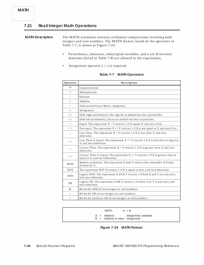
Special Function Programs7-46 SIMATIC 545/555/575 Programming Reference
7.21 Real/Integer Math Operations
The MATH statement executes arithmetic computations involving bothintegers and real numbers. The MATH format, based on the operators inTable 7-7, is shown in Figure 7-24.
• Parentheses, constants, subscripted variables, and a set of intrinsicfunctions (listed in Table 7-8) are allowed in the expressions.
• Assignment operator ( := ) is required.
Table 7-7 MATH Operators
Operator Description
** Exponentiation
* Multiplication
/ Division
+ Addition
– Subtraction/Unary Minus (negation)
:= Assignment
>> Shift right (arithmetic). The sign bit is shifted into the vacated bits.
<< Shift left (arithmetic). Zeros are shifted into the vacated bits.
= Equal. The expression X = Y returns 1 if X equals Y, and zero if not.
< > Not equal. The expression X <> Y returns 1 if X is not equal to Y, and zero if so.
< Less Than. The expression X < Y returns 1 if X is less than Y, and zerootherwise.
<= Less Than or Equal. The expression X <= Y returns 1 if X is less than or equal toY, and zero otherwise.
> Greater Than. The expression X > Y returns 1 if X is greater than Y, and zerootherwise.
>= Greater Than or Equal. The expression X >= Y returns 1 if X is greater than orequal to Y, and zero otherwise.
MOD Modulo arithmetic. The expression X mod Y returns the remainder of X afterdivision by Y.
NOT The expression NOT X returns 1 if X is equal to zero, and zero otherwise.
AND Logical AND. The expression X AND Y returns 1 if both X and Y are non-zero,and zero otherwise.
OR Logical OR. The expression X OR Y returns 1 if either X or Y is non-zero, andzero otherwise.
& Bit-by-bit AND of two integers or real numbers.
| Bit-by-bit OR of two integers or real numbers.
^ Bit-by-bit exclusive OR of two integers or real numbers.
MATH A : = B
A = Address Integer/real, writeableB = Address or value Integer/real
Figure 7-24 MATH Format
MATH
MATH Description

Special Function Programs 7-47SIMATIC 545/555/575 Programming Reference
Table 7-8 MATH Intrinsic Functions
Function Description
ABS Absolute value
ARCCOS Inverse Cosine in radians
ARCSIN Inverse Sine in radians
ARCTAN Inverse Tangent in radians
CEIL CEIL(X) returns the smallest integer that is greater than or equal to X
COS Cosine in radians
EXP Exponential
FLOOR FLOOR(X) returns the largest integer that is less than or equal to X
FRAC FRAC(X) returns the fractional portion of X
LN Natural (base e) Logarithm
LOG Common (base 10) Logarithm
SIN Sine in radians
TAN Tangent in radians
ROUND ROUND(X) returns the integer closest to X
SQRT Square Root
TRUNC TRUNC(X) returns the integer portion of X
The operation of MATH is described below and illustrated in Figure 7-25.
• Each time the MATH statement is executed, the calculations within thestatement are made.
• The MATH computations are executed using the rules of precedence forarithmetic operations listed in Table 7-9. Functions within a group areequivalent in precedence. Execution takes place from left to right for alloperators except exponentiation. For example, in the operation(X * Y / Z), X is multiplied by Y, and the result is divided by Z.
A subexpression enclosed in parentheses is evaluated beforesurrounding operators are applied, e.g., in (X+Y) * Z, the sum of X+Y ismultiplied by Z.
• When you read a discrete point in an SF program expression, a zero isreturned if the discrete bit is off; a one is returned if the discrete bit ison. When you write to a discrete point in an SF program expression, thediscrete bit turns off if the value is zero; the discrete bit turns on if thevalue is non-zero.
• You can use both integers and real numbers in a MATH statement. Thecontroller executes this mixed-mode operation by converting all integersto real on input and rounding the resulting real to integer if thedestination is an integer. (Refer to Section 2.3 for the supported rangeand precision of real numbers.)
MATH Operation
MATH

Special Function Programs7-48 SIMATIC 545/555/575 Programming Reference
Real/Integer Math Operations (continued)
• Real variables are designated by a period following the memory addressor variable name (V300. or LPV35.).
• Denote a binary number by the prefix 0B (e.g.: 0B10111), a hexadecimalnumber by the prefix 0H (e.g.: 0H7FFF). Add the suffix L to denote along (32-bit) signed integer; add the suffix U to denote a 16-bit unsignedinteger. (“L” and “U” integers are supported by PowerMath CPUs only.)
• The programming software checks a statement as you enter it, and, ifnecessary, reports an error by placing the cursor in the field containingthe error.
Table 7-9 Order of Precedence for MATH Operators
Highest Precedence Intrinsic Functions, NOT, Negation NOT –
Exponentiation1 * *
Multiplication, Division, MOD * / MOD
Addition, Subtraction + –
Shift left, Shift right << >>
Relational Operators (= < < = > = < >)
&, Logical AND
|, ^, Logical OR
Lowest Precedence Assignment (:=)1 Execution of exponentiation takes place from right to left. For example, in the operation
(X ** Y ** Z), Y is raised to the power of Z; and then X is raised to the power determinedby the result.
MATH V75.:= 0.929783 * V77. + 2* SQRT ((EXP(V300.) +LN(V302.))/(V304.**0.25))
MATH V100:= V901/(V45. + V46.)
Figure 7-25 MATH Statement Example
Your can use two kinds of subscripted variables. Denote word indexing bythe expression Z(n). Use word indexing to access the nth word from variableZ. Examples of word indexing follow:
V100(1) ≡ V100 V100.(1) ≡ V100. V100L(1) ≡ V100LV100(2) ≡ V101 V100.(2) ≡ V101. V100L(2) ≡ V101LV100(3) ≡ V102 V100.(3) ≡ V102. V100L(3) ≡ V102L
MATH
Using WordIndexing

Special Function Programs 7-49SIMATIC 545/555/575 Programming Reference
Denote element indexing by the expression Z(:n:). Use element indexing toaccess the nth element of an array Z; the actual variable accessed dependsupon the type of array. Examples of element indexing follow:
V100(:1:) ≡ V100 V100.(:1:) ≡ V100. V100L(:1:) ≡ V100LV100(:2:) ≡ V101 V100.(:2:) ≡ V102. V100L(:2:) ≡ V102LV100(:3:) ≡ V102 V100.(:3:) ≡ V104. V100L(:3:) ≡ V104L
For the loop and analog alarm variables, the two kinds of indexing areequivalent, as shown below:
LPV1(1) ≡ LPV1(:1:) ≡ LPV1 LPV1.(1) ≡ LPV1.(:1:) ≡ LPV1.LPV1(2) ≡ LPV1(:2:) ≡ LPV2 LPV1.(2) ≡ LPV1.(:2:) ≡ LPV2.LPV1(3) ≡ LPV1(:3:) ≡ LPV3 LPV1.(3) ≡ LPV1.(:3:) ≡ LPV3.
Since TISOFT does not use multiple subscripts, these expressions are notallowed: Z(n)(m), Z(:n:)(:m:), Z(n)(:m:). Re-code the first two expressions as:
Z(n)(m) ≡ Z(n + m –1)Z(:n:)(:m:) ≡ Z(:n + m –1:)
Re-code the third expression as:
Z(n)(:m:) ≡ Z(n + m –1) when Z is an integer, or a loop or analog alarm variable.
Z(n)(:m:) ≡ Z(n + 2*m –2) when Z is a real number but not a loop or analog alarm variable.
A subscript may itself be an expression [as V100.(V5+2*V7)] and mayinclude real terms. All calculations are done according to the rules of realarithmetic. For example, V100.(12/6) ≡ V100.(2.0) ≡ V101.
Using ElementIndexing
Indexing Loop andAnalog AlarmVariables
Using MultipleSubscripts
MATH

Special Function Programs7-50 SIMATIC 545/555/575 Programming Reference
Real/Integer Math Operations (continued)
The following examples use some of the MATH functions.
• If X = 5.5, then CEIL (X) = 6. If X = –5.9, then CEIL (X) = –5.
• If X = 5.9, then FLOOR (X) = 5. If X = –5.9, then FLOOR (X) = –6.
• The shift right/left functions operate as follows. Assume that V300contains 0000 0000 0000 1000, that equals 8.
V200 := V300 >> 1 places the following value into V200:0000 0000 0000 0100, that equals 4.
V200 := 8 >> 1 places the following value into V200:0000 0000 0000 0100, that equals 4.
V200 := V300 << 1 places the following value into V200:0000 0000 0001 0000, that equals 16.
V200 := 8 << 1 places the following value into V200:0000 0000 0001 0000, that equals 16.
If V400 contains 0000 0000 0000 0011, that equals 3, thenV200 := V300 << V400 places the following value into V200:0000 0000 0100 0000, that equals 64.
For the shift right function, the sign bit is shifted into the vacated bits.If V677 contains 1000 1000 0000 0000, then V677 >> 3 places thefollowing value into V677: 1111 0001 0000 0000.
For the shift left function, zeros are shifted into the vacated bits. If V677contains 0000 0001 0000 0000, then V677 << 3 places the followingvalue into V677: 0000 1000 0000 0000.
MATH
MATH Examples

Special Function Programs 7-51SIMATIC 545/555/575 Programming Reference
7.22 Pack Data
The Pack Data statement moves discrete and/or word data to or from atable. You can access the image register directly by using the PACKstatement. PACK is primarily intended for use in consolidating data so thatit can be efficiently transmitted to a host computer. The PACK format isshown in Figure 7-26.
PACK To/from table = A Table address : B. . . . . . . . . . . . . Number of points = C Data start addr : D. . . . . . . . .
A = T(o) or F(rom)B = Address Integer, writeable if to tableC = Address or value IntegerD = Address or value Integer/real, writeable if from table
Figure 7-26 PACK Format
• A specifies whether you are writing data to or from the table.
• B specifies the address of the table, to or from which data are written orread.
• C is an integer number that specifies how many points or words are tobe moved.
• For a TO table, D specifies the starting address of the points or wordsthat are to be written to the table.For a FROM table, D specifies the starting address in memory intowhich data is to be read from the table.D + (C–1) must be within configured memory range.
• Fields C and D can be repeated for up to 20 writes/reads to and from thetable (Figure 7-27).
PACK To/from table = T Table address : V100. . . . . . . . . . . . . Number of points = 7 Data start addr : C5. . . . . . . . . Number of points = 14 Data start addr : C14. . . . . . . . .
V100V101V102V103
Table
C6
C5
C7
C8
C14
C15
C9
C10
C11
C16
C17
C18
C19
C20
C21
C22
C23
C24
C25
C26
C27
MSB LSB
Figure 7-27 Example of PACKing Multiple Blocks of Bits Into Table
PACK Description
PACK

Special Function Programs7-52 SIMATIC 545/555/575 Programming Reference
Pack Data (continued)
The operation of the PACK TO statement is described below.
• For a TO Table, data are written into a table. This write operationbegins with the data starting at the first Data Start Address and writesthe specified number of points or words into the table, beginning withthe first word of the table.
Bits are written sequentially as illustrated in Figure 7-28 below.
0 0 1 0 1 0 1
0 0 1 0 1 0 1
PACK To/from table = T Table address : V100. . . . . . . . . . . . . Number of points = 7 Data start addr : C5. . . . . . . . .
C6
C5
C7
C9
C8
C10
C11
V100V101V102V103
TableMSB LSB
Figure 7-28 Example of PACKing Bits Into Table
You can specify multiple blocks of data to be written into the table.When the first word of the table is full, PACK begins to fill the secondword.
PACK
PACK TO Operation

Special Function Programs 7-53SIMATIC 545/555/575 Programming Reference
Words are written sequentially into the table, as illustrated inFigure 7-29. You can also PACK multiple blocks of words.
Word image register
PACK To/from table = T Table address : V100. . . . . . . . . . . . . Number of points = 3 Data start addr : WX77. . . . . . . . . Number of points = 2 Data start addr : V992. . . . . . . . .
V100V101V102V103
WX77WX78WX79
V992
0 0 1 0 1 0 1 0 0 1 0 1 0 1 0 1 0 0 1 0 1 0 1 0 0 1 0 1 0 1 0 11 0 0 1 1 0 0 0 0 0 0 1 1 1 1 11 0 0 1 1 0 0 0 0 0 0 1 1 1 1 1
1 1 1 1 1 1 0 0 0 0 0 0 0 0 1 0 1 1 1 1 1 1 0 0 0 0 0 0 0 0 1 00 0 0 0 1 1 1 1 1 1 1 1 1 1 1 0
0 0 0 0 1 1 1 1 1 1 1 1 1 1 1 0
Table
V104 1 1 1 1 1 1 1 1 1 1 1 1 1 1 1 0
V993 1 1 1 1 1 1 1 1 1 1 1 1 1 1 1 0
V-Memory
MSB LSB
Figure 7-29 Example of PACKing Words Into Table
• You can PACK blocks of words and blocks of bits into a table with onePACK statement. See Figure 7-30. The data are PACKed according tothese rules.
Discrete points are PACKed into the next available bit in the table.
Words are PACKed into the next available word in the table. Unusedbits in the previous word fill with zeros when a word is written to thetable.
PACK To/from table = T Table address : V100. . . . . . . . . . . . . Number of points = 7 Data start addr : C5. . . . . . . . . Number of points = 14 Data start addr : C14. . . . . . . . . Number of points = 3 Data start addr : WX77. . . . . . . . . Number of points = 2 Data start addr : V992. . . . . . . . .
V100V101V102V103
Table
C6
C5
C7
C8
C14
C15
C9
C10
C11
C16
C17
C18
C19
C20
C21
C22
C23
C24
C25
C26
C27
WX77WX78WX79
V992
0 0 0 0 0 0 0 0 0 0 0
Word image register
V993
V104V105V106
V-Memory
MSB LSB
Figure 7-30 Example of PACKing Bits and Words Into Table
PACK

Special Function Programs7-54 SIMATIC 545/555/575 Programming Reference
Pack Data (continued)
The operation of the PACK FROM statement is described below.
• For a FROM Table, data are read from a table. This read operationbegins with the table starting address and reads the specified number ofpoints or words from the table. PACK then writes this data, startingwith the address designated in the Data Start Address.
Bits are written sequentially as illustrated in Figure 7-31.
0 0 1 0 1 0 1
0 0 1 0 1 0 1
PACK To/from table = F Table address : V100. . . . . . . . . . . . . Number of points = 7 Data start addr : C5. . . . . . . . .
C6
C5
C7
C9
C8
C10
C11
V100V101V102V103
TableMSB LSB
Figure 7-31 Example of PACKing Bits from a Table
You can specify multiple blocks of data to be PACKed from the table, asillustrated in Figure 7-32. You cannot skip sections of the table to PACKdata located within the table. For example, refer to Figure 7-32. If thedata that you want to read are located in the least significant nine bitsof V100 and the most significant five bits of V101, you must still PACKout the first seven bits of V100 and discard them.
V100
PACK To/from table = F Table address : V100. . . . . . . . . . . . . Number of points = 7 Data start addr : C5. . . . . . . . . Number of points = 14 Data start addr : C14. . . . . . . . .
V101V102V103
Table
C6
C5
C7
C8
C14
C15
C9
C10
C11
C16
C17
C18
C19
C20
C21
C22
C23
C24
C25
C26
C27
MSB LSB
Figure 7-32 Example of PACKing Multiple Blocks of Bits from a Table
PACK
PACK FROMOperation

Special Function Programs 7-55SIMATIC 545/555/575 Programming Reference
Words are read sequentially from the table, as illustrated in Figure 7-33.You can also PACK multiple blocks of words.
Word image registerV100
PACK To/from table = F Table address : V100. . . . . . . . . . . . . Number of point = 3 Data start addr : WX77. . . . . . . . . . Number of points = 2 Data start addr : V992. . . . . . . . .
V101V102V103
WX77WX78WX79
V992
0 0 1 0 1 0 1 0 0 1 0 1 0 1 0 1 0 0 1 0 1 0 1 0 0 1 0 1 0 1 0 11 0 0 1 1 0 0 0 0 0 0 1 1 1 1 11 0 0 1 1 0 0 0 0 0 0 1 1 1 1 1
1 1 1 1 1 1 0 0 0 0 0 0 0 0 1 0 1 1 1 1 1 1 0 0 0 0 0 0 0 0 1 00 0 0 0 1 1 1 1 1 1 1 1 1 1 1 0
0 0 0 0 1 1 1 1 1 1 1 1 1 1 1 0
Table
V104 1 1 1 1 1 1 1 1 1 1 1 1 1 1 1 0
V993 1 1 1 1 1 1 1 1 1 1 1 1 1 1 1 0
V-Memory
MSB LSB
Figure 7-33 Example of PACKing Words from a Table
• You can PACK blocks of words and blocks of bits from a table with onePACK statement. See Figure 7-34. The data are packed according tothese rules.
All discrete points designated in the Number of Points field are packedfrom the table.
Words are packed from the first available word in the table. That is,unused bits in the previous word of the table are not included as part ofa word that is PACKed from the table.
BitImageRegister
PACK To/from table = F Table addr : V100. . . . . . . . . . . . . . . . Number of points = 7 Data start addr : C5. . . . . . . . . Number of points = 14 Data start addr : C14. . . . . . . . . Number of points = 3 Data start addr : WX77. . . . . . . . . Number of points = 2 Data start addr : V992. . . . . . . . .
V100V101V102V103
Table
C6
C5
C7
C8
C14
C15
C9
C10
C11
C16
C17
C18
C19
C20
C21
C22
C23
C24
C25
C26
C27
WX77WX78WX79
V992
Word image register
V993
V104V105V106
V-Memory
MSB LSB
Figure 7-34 Example of PACKing Bits and Words from a Table
PACK

Special Function Programs7-56 SIMATIC 545/555/575 Programming Reference
7.23 Pack Analog Alarm Data
The Pack Analog Alarm Data statement moves analog alarm data to or froma table. PACKAA is primarily intended for use in consolidating analogalarm data to be accessed from an operator interface. The PACKAA formatis shown in Figure 7-35.
PACKAA To/from table : A Table address : B. . . . . . . . Alarm number : C. . . . Parameters : D. . . . . .
A = T(o) or F(rom)B = Address Integer, writeable if to tableC = Address or value IntegerD = Element Integer/real, writeable if from table, only
analog alarm data types
Figure 7-35 PACKAA Format
• A specifies whether you are writing data to or from the table.
• B specifies the address of the table, to or from which data are moved.
• C specifies the number of the analog alarm to be accessed. C may rangefrom 1 to the maximum number of alarms.
• D specifies the analog alarm variables. Up to eight variables can bedesignated. See Table 7-10 for a list of the analog alarm variables.
Table 7-10 Analog Alarm Variables
Mnemonic Variable Name Mnemonic Variable Name
AACK Acknowledge APV* Process Variable
AADB* Deadband APVH. Process Variable High Limit
ACF C-Flags (32 bits) APVL. Process Variable Low Limit
ACFH Most Significant Word of C-Flags ARCA. Rate of Change Alarm Limit
ACFL Least Significant Word of C-Flags ASP* Set Point
AERR* Error ASPH* Set Point High Limit
AHA* High Alarm Limit ASPL* Set Point Low Limit
AHHA* High-High Alarm Limit ATS. Sample Rate
ALA* Low Alarm Limit AVF V Flags
ALLA* Low-Low Alarm Limit AYDA* Yellow Deviation Alarm Limit
AODA* Orange Deviation Alarm Limit
* Variables with an asterisk can be either a real number or an integer. Variables followed by a period arereal numbers. Variables not followed by a period are integers. When you execute PACKAA using realnumbers, two memory locations are allocated for each real number.
PACKAA
PACKAADescription

Special Function Programs 7-57SIMATIC 545/555/575 Programming Reference
The operation of the PACKAA statement is described below and illustratedin Figure 7-36 and Figure 7-37. When the PACKAA statement executes, thefollowing actions occur.
• For a TO Table, the value of the analog alarm variable specified in D iswritten into the table at the address designated by B.
If additional variables are specified, the second variable is written to(B + 1), the third to (B + 2), and so on up to eight variables.
S-MemoryTableMSB LSB
APV.
AACK
ASP.
AODA
V100V101V102V103
1 1 1 1 1 1 1 1 1 1 1 1 1 1 1 10 0 0 0 0 0 0 0 0 0 0 0 0 0 0 00 0 0 0 0 0 0 0 0 0 0 0 0 0 0 01 1 1 1 1 1 1 1 1 1 1 1 1 1 1 1
V104 1 1 1 1 1 1 1 1 1 1 1 1 1 1 1 10 0 0 0 0 0 0 0 0 0 0 0 0 0 0 0
1 1 1 1 1 1 1 1 1 1 1 1 1 1 1 1
0 0 0 0 0 0 0 0 0 0 0 0 0 0 0 00 0 0 0 0 0 0 0 0 0 0 0 0 0 0 0
1 1 1 1 1 1 1 1 1 1 1 1 1 1 1 11 1 1 1 1 1 1 1 1 1 1 1 1 1 1 1
0 0 0 0 0 0 0 0 0 0 0 0 0 0 0 0V105
PACKAA To/from table : T Table address. : V100 . . . . . . . . . . . . Alarm number : 10. . . . . . . . Parameters : AACK APV. ASP. AODA. . . . . . . . . .
Figure 7-36 Example of PACKAA TO Table Operation
• For a FROM Table, PACKAA writes the word in the table startingaddress B into the specified analog alarm variable.
If additional variables are specified, the second word in the table iswritten to the second variable, and so on up to eight variables.
TableMSB LSBV100V101V102V103
1 1 1 1 1 1 1 1 1 1 1 1 1 1 1 10 0 0 0 0 0 0 0 0 0 0 0 0 0 0 00 0 0 0 0 0 0 0 0 0 0 0 0 0 0 01 1 1 1 1 1 1 1 1 1 1 1 1 1 1 1
V104 1 1 1 1 1 1 1 1 1 1 1 1 1 1 1 10 0 0 0 0 0 0 0 0 0 0 0 0 0 0 0V105
PACKAA To/from table : F Table address. : V100 . . . . . . . . . . . . Alarm number : 10. . . . . . . . Parameters : AACK APV. ASP. AODA. . . . . . . . . .
S-MemoryAACK
APV.
ASP.
AODA
1 1 1 1 1 1 1 1 1 1 1 1 1 1 1 1
0 0 0 0 0 0 0 0 0 0 0 0 0 0 0 00 0 0 0 0 0 0 0 0 0 0 0 0 0 0 0
1 1 1 1 1 1 1 1 1 1 1 1 1 1 1 11 1 1 1 1 1 1 1 1 1 1 1 1 1 1 1
0 0 0 0 0 0 0 0 0 0 0 0 0 0 0 0
Figure 7-37 Example of PACKAA FROM Table Operation
PACKAA Operation
PACKAA

Special Function Programs7-58 SIMATIC 545/555/575 Programming Reference
7.24 Pack Loop Data
The PACKLOOP statement (Figure 7-38) moves loop data to or from a table.PACKLOOP is primarily intended for use in consolidating loop data to beaccessed from an operator interface.
PACKLOOP To/from table : A Table address : B. . . . . . . . Loop number : C. . . . Parameters : D. . . . . .
A = T(o) or F(rom)B = Address Integer, writeable if to tableC = Address or value IntegerD = Element Integer/real, writeable if from table, only
loop data types
Figure 7-38 PACKLOOP Format
• A specifies whether you are writing data to or from the table.
• B specifies the address of the table, to or from which data are moved.
• C specifies the number of the loop to be accessed. The range for C isfrom 1 to the maximum number of loops.
• D specifies the loop variables. Up to eight variables can be designated.See Table 7-11 for a list of the loop variables.
The operation of the PACKLOOP statement is described below. PACKLOOPoperates similarly to the PACKAA statement. See Figure 7-36 andFigure 7-37 for an example of how the PACKLOOP statement executes.
When the PACKLOOP statement executes the following actions occur.
• For a TO Table, the value of the loop variable specified in D is writteninto the table at the address designated by B.
If additional variables are specified, the second variable is written to(B + 1), the third to (B + 2), and so on up to eight variables.
• For a FROM Table, PACKLOOP writes the word in the table startingaddress B into the specified loop variable.
If additional variables are specified, the second word in the table iswritten to the second variable, and so on up to eight variables.
PACK-LOOP
PACKLOOPDescription
PACKLOOPOperation

Special Function Programs 7-59SIMATIC 545/555/575 Programming Reference
Table 7-11 Loop Variables
Mnemonic Variable Name
LACK Alarm Acknowledge
LADB* Alarm Deadband
LCF C-Flags (32 bits)
LCFH Most Significant Word of C-Flags
LCFL Least Significant Word of C-Flags
LERR* Error
LHA* High Alarm Limit
LHHA* High-high Alarm Limit
LKC. Gain
LKD. Derivative Gain Limiting Coefficient
LLA* Low Alarm Limit
LLLA* Low-low Alarm Limit
LMN* Output
LMX* Bias
LODA* Orange Deviation Alarm Limit
LPV* Process Variable
LPVH. Process Variable High Limit
LPVL. Process Variable Low Limit
LRCA. Rate of Change Alarm Limit
LRSF Ramp/Soak Flags
LRSN Ramp/Soak Step Number
LSP* Set Point
LSPH* Set Point High Limit
LSPL* Set Point Low Limit
LTD. Rate
LTI. Reset
LTS. Sample Rate
LVF V-Flags
LYDA* Yellow Deviation Limit
* Variables with an asterisk can be either a real number or an integer.Variables followed by a period are real numbers. Variables not followed by aperiod are integers. When you execute PACKLOOP using real numbers, twomemory locations are allocated for each real number.
PACK-LOOP

Special Function Programs7-60 SIMATIC 545/555/575 Programming Reference
7.25 Pack Ramp/Soak Data
The Pack Ramp/Soak Data statement moves one or more elements (steps) ofthe ramp/soak profile for a given loop to or from a table. PACKRS isprimarily intended to make the ramp/soak profiles accessible to an operatorinterface and to provide a method for dynamic ramp/soak profiling. ThePACKRS format is shown in Figure 7-39.
PACKRS TO/FROM TABLE : A. . LOOP NUMBER : C. . . NO. OF STEPS : D. . . .
TABLE ADDRESS : B. .
STARTING STEP : E. .
A = T(o) or F(rom)B = Address Integer, writeable if to table. . . . . . . . . . . . . C = Address or value Integer. . . . . D = Address or value Integer. . . . . E = Address or value Integer. . . . . .
Figure 7-39 PACKRS Format
• A specifies whether you are writing data to or from the table.
• B specifies the address of the table, to or from which data are moved.
• C specifies the loop number whose ramp/soak profile is involved in thepack operation.
• D specifies the number of ramp/soak steps to pack.
• E specifies the starting step in the ramp/soak profile at which the packoperation will begin.
The number of steps in a ramp/soak profile is established when it isprogrammed using TISOFT or your programming package. The PACKRSinstruction cannot expand or shorten the ramp/soak profile for a given loop.This instruction can only read or modify existing steps in a preexistingprofile.
PACKRS instructions that specify operations on non-existent profile stepsare invalid, and the execution of this instruction terminates.
PACKRS
PACKRS Description
PACKRS Operation

Special Function Programs 7-61SIMATIC 545/555/575 Programming Reference
If TO Table is specified, this instruction copies the specified number of stepsfrom the ramp/soak profile of a given loop, starting at the specified stepnumber, to a table in memory whose starting address is indicated in theinstruction.
If FROM Table is specified, this instruction copies the specified number ofprofile steps from a memory table into the ramp/soak profile for theindicated loop starting at the specified step number. The new step valuesoverwrite the affected step values in the profile.
NOTE: Care should be taken when using the PACKRS instruction with aFROM Table specified. If the ramp/soak profile being modified is in progresswhen the PACKRS instruction executes, then your process could reacterratically due to the sudden replacement of values in the profile steps. Youcan use one of the following methods to ensure that the profile update isdone when the current profile is not in progress.
• In your program, check the state of the profile finished bit (bit 4) inLRSF for the corresponding loop. Do not execute the PACKRSstatement unless the finished bit is set.
• In your program, place the loop in the manual mode, execute thePACKRS to update the ramp/soak profile, then return the loop toautomatic mode. (Remember, this causes the ramp/soak profile to berestarted at the initial step.)
PACKRS

Special Function Programs7-62 SIMATIC 545/555/575 Programming Reference
Pack Ramp/Soak Data (continued)
When stored in a memory table, ramp/soak profile steps are six words longand have the following format:
• Word 1 (bit 1): Step type — 0 = ramp step, 1 = soak step (bit)
• Word 1 (bits 2–16) + Word 2: Address of status bit (special addressformat)
• Words 3/4: Setpoint, if ramp step, or Soak time, if soak step (REALnumber)
• Words 5/6: Ramp rate, if ramp step, or Deadband, if soak step (REALnumber)
The status bit address points to either an output point (Y) or a control relay(C). This address takes a short form for point numbers C1 – C512 andY1 – Y1024. Higher point numbers use a long form of address. If all bits ofthe status bit address field are 0, then no status bit is selected for the step.
The short address form is shown in Figure 7-40.
MSB LSB16151413121110987654321
Word 1
0000000000000000
Point Type Offset
Word 2
S
S = Step type: 0 = ramp step, 1 = soak stepPoint Type = 0 0 0 ⇒ control relay (C)
1 1 0 ⇒ output (Y)Offset = same as point number
Figure 7-40 Address Format — Short Form
For example, the encoded address for Y23 using the short form is shown inFigure 7-41.
Word 1
Word 2
Ramp step with status bit Y23
0000000000000000
1110100000000110
S = 0 (Ramp step)Point Type = 110 (Y output)Offset = 017 Hex (23)
MSB LSB16151413121110987654321
Figure 7-41 Short Form Address Example
PACKRS

Special Function Programs 7-63SIMATIC 545/555/575 Programming Reference
The long address form is shown in Figure 7-42.
MSB LSB16151413121110987654321
Word 1
Point Type
Page Number
Word 2
0000111
S = Step type: 0 = ramp step, 1 = soak stepPoint Type = 0 0 0 ⇒ control relay (C)
1 1 0 ⇒ output (Y)Page Number = (Point number – 1) / Page sizeOffset = offset within current page
Offset = ((Point number – 1) modulo Page size) + 1NOTE: Page size = 512 for control relays (C), 1024 for output points (Y)
Offset0
S
Figure 7-42 Address Format — Long Form
For example, the encoded address for C514 using the long form is shown inFigure 7-43.
MSB LSB16151413121110987654321
Word 1
Word 2
1000000000001111
0100000000000000
Soak step with status bit C514
S = 1 (Soak step)Point Type = 000 (C control relay)Page Number: (514 – 1) / 512 = 1Offset: ((514–1) modulo 512) + 1 = 2
Figure 7-43 Long Form Address Example
PACKRS

Special Function Programs7-64 SIMATIC 545/555/575 Programming Reference
Pack Ramp/Soak Data (continued)
Figure 7-44 shows an example of the PACKRS instruction moving valuesfrom a ramp/soak profile to a V-memory table.
Table in V-Memory
8 0 2 1
0 0 0 0
4 0 C 0
0 0 0 0
3 F C 0
0 0 0 0
0 2 0 0
0 0 0 0
4 2 8 2
0 0 0 0
4 0 C 0
0 0 0 0
F 0 0 1
0 0 0 1
4 1 2 0
0 0 0 0
4 0 6 0
0 0 0 0
Table after execution of PACKRSinstruction To Table, from Loop 2,packing 3 steps, starting at step 2.
Loop 2 RAMP/SOAK Profile
Step R/SStatus
BitSetpoint(Units)
Ramp Rate(Units/Min)
Soak Time(Min)
Deadband(Units)
Step 2 Values
Step 3 Values
Step 4 Values
V100V101V102V103V104V105V106V107V108V109V110V111V112V113V114V115V116V117
PACKRS To/from Table : TO. . Loop Number : 2. . No. of Steps : 3. . .
Table Address : V100.
Starting Step : 2. . .
1
2
3
4
5
Ramp C32 56.2 3.6
Soak C33 6.0 1.5
Ramp C512 65.0 6.0
Soak C513 10.0 3.5
Ramp C1025 45.0 5.0
Soak step; status bit address C33
IEEE floating-point representation of 6.0
IEEE floating-point representation of 1.5
IEEE floating-point representation of 65.0
IEEE floating-point representation of 6.0
Ramp step; status bit address C512
Soak step; status bit address C513
IEEE floating-point representation of 10.0
IEEE floating-point representation of 3.5
Figure 7-44 Example of PACKRS to a Table in V-Memory
PACKRS

Special Function Programs 7-65SIMATIC 545/555/575 Programming Reference
Figure 7-45 shows an example of the PACKRS instruction moving valuesfrom a V-memory table to a Loop Ramp/Soak profile, changing two of thevalues in the profile, and leaving the remaining values unchanged.
Table in V-Memory
6 4 0 0
0 0 0 0
4 2 2 0
0 0 0 0
4 0 A 0
0 0 0 0
F 0 0 1
6 0 0 1
4 1 2 0
0 0 0 0
4 0 A 0
0 0 0 0
Loop 1 RAMP/SOAK Profile before PACKRS is executed
Ramp step; status bit address Y1024V1000V1001V1002V1003V1004V1005V1006V1007V1008V1009V1010V1011
IEEE floating-point representation of 40.0
IEEE floating-point representation of 5.0
IEEE floating-point representation of 10.0
IEEE floating-point representation of 5.0
Soak step; status bit address Y1025
Loop 1 RAMP/SOAK Profile after PACKRS is executed
Step R/SStatus
BitSetpoint(Units)
Ramp Rate(Units/Min)
Soak Time(Min)
Deadband(Units)
In this example, the Ramp/Soak profile for Loop 1 is changed after executing the PACKRS instruction.The Setpoint value in Step 1 is modified from 30.0 to 40.0 and the Soak Time value in Step 2 is changedfrom 3.0 to 10.0. All other values in the profile have been left unchanged.
PACKRS To/from Table : FROM. . Loop Number : 1. . No. of Steps : 2. . .
Table Address : V1000.
Starting Step : 1. . .
1
2
3
4
Ramp Y1024 30.0 5.0
Soak Y1025 3.0 5.0
Ramp Y1026 20.0 4.0
Soak Y1027 5.0 6.5
Step R/SStatus
BitSetpoint(Units)
Ramp Rate(Units/Min)
Soak Time(Min)
Deadband(Units)
Ramp Y1024 40.0 5.0
Soak Y1025 10.0 5.0
Ramp Y1026 20.0 4.0
Soak Y1027 5.0 6.5
1
2
3
4
Step 1 Values
Step 2 Values
Figure 7-45 Example of PACKRS from a Table in V-Memory
PACKRS

Special Function Programs7-66 SIMATIC 545/555/575 Programming Reference
7.26 Pet Scan Watchdog
PETWD (Pet Scan Watchdog) allows you to extend the scan watchdog limitwhile performing an in-line SF program or SF subroutine from an RLLprogram. When the PETWD instruction executes, the scan watchdog timeris reset at that instance of time during the scan, therefore extending thescan watchdog limit beyond the configured scan watchdog limit.
A possible use would be in a large table lookup operation performed whilethe controlled process is at a steady-state condition.
The RETURN format has no subfields.
The PETWD instruction is intended to be used in the normal RLL task(TASK 1).
PETWD is available only for in-line compiled SF programs or subroutines inCPUs that support PowerMath.
! WARNINGThe PETWD instruction allows you to place the PETWD instruction in an infiniteloop, therefore preventing the scan watchdog limit from ever being reached.
If the PETWD instruction is in an infinite loop, the PLC would not issue a scanwatchdog FATAL ERROR to shut the process down, therefore leaving yourprocess uncontrolled. An uncontrolled process could result in death or seriousinjury to personnel, and/or damage to equipment.
Ensure that the PETWD instruction is not located in an infinite loop. T o ensurethat the PETWD instruction is not located in an infinite loop within an SFprogram or subroutine, place the PETWD instruction without a label at thebeginning of the SF program or subroutine.
PETWD
PETWD Description

Special Function Programs 7-67SIMATIC 545/555/575 Programming Reference
PETWD

Special Function Programs7-68 SIMATIC 545/555/575 Programming Reference
7.27 Printing
The Print statement sends a message to the ASCII communication ports.This statement can be used to print both text and the contents of integerand real variables. The PRINT format is shown in Figure 7-46.
A = 1B = Address Text enclosed in double quotes
PRINT Port : A Message :. . . . . . . . B:
Figure 7-46 PRINT Format
• A is the port number. You must enter a 1 in this field.
• B contains a free format message. The message begins on the linefollowing the port and message designator fields. Element addressesand Expressions are separated by a space. No embedded space or theassignment operator (:=) in an expression is accepted.
The operation of the PRINT statement is described below.
• When the PRINT statement executes, the message is sent to the port(s)specified.
• The maximum message length is 1019 characters, with characterscounted in entries as follows:Each text character = 1 characterEach variable entry = 6 charactersEach variable text entry = 6 charactersCarriage Return & Linefeed = 2 characters
• Text Entries contain ASCII text to be printed. Text entries are enclosedin quotation marks.
Example: PRINT PORT=1 MESSAGE:“END OF SHIFT REPORT”
• Variable Entries print the contents of variables in either integer or realformat. Variables must be separated by spaces. Real numbers areindicated by following the address with a period (.). Integers are printedright-justified in a six character field with a floating minus sign. Realnumbers are printed right-justified in a twelve character field using aFORTRAN G12.5 format.
Example: PRINT PORT=1 MESSAGE:“THE VALUES ARE” WX5 V104.
PRINT Description
PRINT Operation

Special Function Programs 7-69SIMATIC 545/555/575 Programming Reference
• Time Entries are used to print out a variable in time format. Thevariable is printed out as hh:mm:ss. Time entries are indicated byfollowing the address of the variable (EL or EXP) with :TIME.
Example: PRINT PORT=1 MESSAGE:“THE TIME IS NOW” STW141:TIME
• Date Entries are used to print out a variable in date format. Thevariable is printed out as yy/mm/dd. Date entries are indicated byfollowing the address of the variable (EL or EXP) with :DATE.
Example: PRINT PORT=1 MESSAGE: “THE DATE IS NOW” STW141:DATE
• Variable Text Entries are used to print out text stored in either V or Kmemory. Variable Text Entries are indicated by following the address ofthe text (EL or EXP) to be printed with a percent sign (%) and thenumber of characters to be printed. If the number is coded as zero,PRINT assumes that the first word of the indicated variable containsthe number of characters to print.
Example: PRINT PORT=1 MESSAGE: “BOILER” V250%16“DESCRIPTION” V102%0
“Boiler” V250%16 causes the 16 characters in V-Memory locationsV250–V257 to be printed. Each word contains two 8-bit characters.
“Description” V102%0 causes the number of characters specified in V102to be printed. If V102 contains 5, then the characters in V103–V105 areprinted.
Variable Text Entries are a valuable tool for embedding control characters tobe used by the device receiving the ASCII characters. The next page givesinstructions about how to embed a control character in variable text.
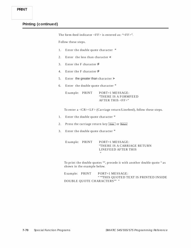
Special Function Programs7-70 SIMATIC 545/555/575 Programming Reference
Printing (continued)
The form-feed indicator <FF> is entered as: “<FF>”.
Follow these steps.
1. Enter the double quote character “
2. Enter the less than character <
3. Enter the F character F
4. Enter the F character F
5. Enter the greater than character >
6. Enter the double quote character ”
Example: PRINT PORT=1 MESSAGE: “THERE IS A FORMFEED AFTER THIS <FF>”
To enter a <CR><LF> (Carriage return/Linefeed), follow these steps.
1. Enter the double quote character “
2. Press the carriage return key Enter or Return
3. Enter the double quote character ”
Example: PRINT PORT=1 MESSAGE: “THERE IS A CARRIAGE RETURN LINEFEED AFTER THIS ”
To print the double quotes ““, precede it with another double quote “ asshown in the example below.
Example: PRINT PORT=1 MESSAGE: “ ““THIS QUOTED TEXT IS PRINTED INSIDE
DOUBLE QUOTE CHARACTERS”” ”

Special Function Programs 7-71SIMATIC 545/555/575 Programming Reference
7.28 Return from SF Program/Subroutine
The Return statement is used to terminate an SF program or anSF subroutine. If invoked from an SF program, the program terminates. Ifinvoked from an SF subroutine, control returns to the statement in theSF program following the SF subroutine call. The RETURN format has nosubfields. If there is no RETURN statement, the program terminates afterthe last statement. The format of the RETURN statement is shown inFigure 7-47.
<SF Statement><SF Statement><SF Statement>RETURN
Figure 7-47 Example of the RETURN Statement
RETURN

Special Function Programs7-72 SIMATIC 545/555/575 Programming Reference
7.29 Scaling Values
The Scale statement uses as input an integer input and converts it toengineering units scaled between high and low limits. The SCALE format isshown in Figure 7-48.
SCALE Binary input : A Scaled result : B. . . . . . . Low limit : C High limit : D. . . . . . . . . . . . . 20% offset : E Bipolar : F. . . . . . . . . . . . . .
A = Address IntegerB = Address Integer/real, writeableC = Literal constant Real (C ≤ D)D = Literal constant Real (C ≤ D)E = Y(es) or N(o)F = Y(es) or N(o)
Figure 7-48 SCALE Format
• A is the memory location of the input.
• B is the memory location of the result after conversion.
• C is the lower limit to which the input can be scaled.
• D is the upper limit to which the input can be scaled.
• E indicates if the input is 20% offset (Yes) or 0% offset (No).
• F indicates if the input is bipolar (Yes) or not (No).
NOTE: You cannot choose both bipolar and 20% offset for an input (Fields E–F).
SCALE
SCALE Description

Special Function Programs 7-73SIMATIC 545/555/575 Programming Reference
The operation of the Scale statement is described below and illustrated inFigure 7-49.
• Each time the SCALE statement executes, an integer located in Aconverts to an integer or real number in engineering units, scaledbetween high and low limits.
If the input is a variable that could range from –32000 to +32000, thevariable is bipolar. Set option F to Y(es). If the input is a variable thatcould range from 0 to 32000, the variable is unipolar. Set option F toN(o).
If the input is a variable that has a 20% offset (ranges from 6400 to32000), set option E to Y(es). If the input is a variable that has a 0%offset, set option E to N(o).
• The result is stored in the address specified by B.
The low and high limits specified in C and D determine the range of theconverted number. Values of C and D may fall within the followinglimits.
5.42101070 * 10�20 9.22337177 * 1018to
� 9.22337177 * 1018� 2.71050535 * 10�20to
Range =
• An error is logged if the input value is outside the low-limit to high-limitrange; and the output is clamped to the nearer of either the low limit orthe high limit.
You can use the SCALE statement to convert an input signal from an analoginput module to a value in engineering units. For example, consider theseconditions.
• The input is a 4–20 mA signal that is converted by the analog inputmodule to a value between 6400 and 32000 (unipolar, 20% offset) andsent to WX33.
• You want the result of the SCALE statement to be a real numberranging between 0 and 100 and be placed in V100., as shown below.
The SCALE fields would contain these values.
SCALE Binary input : WX33 Scaled result : V100.. . . . . . . . . . . . . . Low limit : 0 High limit : 100. . . . . . . . . . . . . . . . . . . . 20% offset : Y Bipolar : N. . . . . . . . . . . . . . . . . . . . .
Figure 7-49 SCALE Example
SCALE Operation
SCALE

Special Function Programs7-74 SIMATIC 545/555/575 Programming Reference
7.30 Sequential Data Table
The Sequential Data Table statement moves words one at a time from anexisting table to a destination address. A pointer designates the address ofthe next word in the table to be moved. Each time the statement isexecuted, one word moves and replaces the word at the destination address.The SDT format is shown in Figure 7-50.
SDT Input table : A Output : B. . . . . . . . . . . . . . Table PTR : C Table length : D. . . . . . . . . Restart bit : E. . . . .
A = Address Integer/realB = Address Integer/real, writeableC = Address Integer, writeableD = Address or value IntegerE = Element Bit, writeable
Figure 7-50 SDT Format
• A is the starting address for the table. When used in a compiled SFprogram or subroutine, you must specify a static table; that is, thetable’s base address must be a V, K, G, VMS, or VMM address.
• B is the output address to which the words are moved. When used in acompiled SF program or subroutine, you must specify a static table; thatis, the table’s base address must be a V, K, G, VMS, or VMM address.
• C is the address of the pointer.
• D is the length of the table and must be a value greater than zero. Whenused in a compiled SF program or subroutine, the table length must bespecified as a value.
• E is the address of the restart (status) bit and can be a C or Y.
The operation of the SDT statement is described below and illustrated inFigure 7-51.
• The SDT moves words from a pre-existing table.
The size of the table depends upon the memory location that you chooseand, if the memory is user-configurable, how much memory youallocated.
• Before the SDT is executed, pointer C contains zero. You must designyour program to set the pointer to zero.
SDT
SDT Description
SDT Operation

Special Function Programs 7-75SIMATIC 545/555/575 Programming Reference
• Each time the SDT is executed, the following actions occur:
The table pointer is incremented by 1. Then the word in the tablelocation specified by the pointer is moved to the destination addressspecified by B.
The process is repeated until the number of words specified in D hasbeen moved.
• When the last word has been moved, the pointer is reset to zero.
• The restart bit E is on, except for the following conditions:
When the SDT resets the pointer, the restart bit turns off.
Prior to the first execution of the SDT, the bit could be either off or ondepending upon prior usage.
The value of the pointer does not change when the SDT is not executing. Allvalues in the table remain the same, and destination address B contains thevalue of the last word moved from the table.
You can use other logic to reset the pointer to zero, but the restart bit doesnot turn off.
SDT Input table :V200 Output :V100. . . . . . . . . . . . . . Table PTR :V500 Table length :30. . . . . . . . . Restart bit :C77. . . . .
V200
V229
Table Starting Address A = V200
~~~~
1st word moved from table
30th word moved from table
V201
V202
V228
V227
Pointer CDestination Address B = V100Word moved from table
V500 = 1
V500 = 2
V500 = 3
V500 = 28
V500 = 29
V500 = 0
V100
C77 = ON
C77 = ON
C77 = ON
C77 = ON
C77 = ON
C77 = OFF
Restart Bit Eis C77V500
Value of restart bitafter word moved
from table
1
2
3
4
29
27
28
30
Value of pointerafter word moved
from table.
Figure 7-51 SDT Statement Example
Before the SDT executes, the pointer V500 contains 0 (zero). When thestatement executes, the pointer increments by 1, and the value in V200 ismoved to V100. This process repeats each time the statement executes.After the last word is moved, the pointer resets to 0.
SDT

Special Function Programs7-76 SIMATIC 545/555/575 Programming Reference
7.31 Synchronous Shift Register
The Synchronous Shift Register statement builds a table that functions assynchronous shift register. The SSR format is shown in Figure 7-52.
SSR Register start. : A Status bit : B. . . . Register length : C. .
A = Address Integer/real, writeableB = Element Bit, writeableC = Address or value Integer
Figure 7-52 SSR Format
• A is the starting address for the shift register.
• B is the status bit (C or Y) and is turned on when the register is empty.
• C is the length of the shift register. The maximum number of elementsstored in the register is C. If a constant value is entered, it must begreater than zero.
The operation of the SSR statement is described below and illustrated inFigure 7-53.
• The starting address A designates the memory area in which the shiftregister is located.
• The register length C determines the size of the shift register. Sizedepends upon the memory location that you choose and how muchmemory you allocated (if the memory is user-configurable). Themaximum number of elements stored in the register is C.
• The first position of the register, Register Start A, is empty until anelement moves into A from another source.
• Each time the SSR executes, the element currently in memory locationA shifts to A + 1. The element in A + 1 shifts to A + 2. Elements movedown the shift register to A + 3, A + 4, etc., and A resets to zero.
• After the register is full, shifting in a new word causes the loss of thelast word in the register at location [A + (C – 1)].
• The register is considered empty when it contains all zeros. The statusbit B turns on when the register is empty.
NOTE: If the register contains the value –0.0, the register is not recognizedas empty, and the status bit does not turn off.
SSR
SSR Description
SSR Operation

Special Function Programs 7-77SIMATIC 545/555/575 Programming Reference
V100
V101
V102
V103
V104
• The application program moves a word into the SSR from WY37.
• The application program moves a word into V100.• The register start address V100 now contains the value 7988.
• The word 7988 shifts to V101.• Register start address V100 is reset to 0 (V100 = 0).• The Status Bit (C17) is turned off.
• Register start address V100 contains the value 6655.• Shift register location V101 contains the value 7988.• The Status Bit (C17) is off.
Shift register status before first word is moved in.
SSR executes one time.
Shift register status after application program moves firstword in; SSR has not executed yet.
Shift register status after application program movessecond word in. Another word source (WY200) is used.
V100
V101
V102
V103
V104
V100
V101
V102
V103
V104
V100
V101
V102
V103
V104
C17 IS OFF
C17 IS OFF
C17 IS OFF
WY377988
WY377988
0000
0
79880000
Word source
Word source
Word source
Word source
7988000
0
WY2006655
0
00
79886655
WY377988
• The word 7988 shifts to V102.• The word 6655 shifts to V101.• Register start address V100 is reset to 0 (V100 = 0).• The Status Bit (C17) is off.
SSR executes one time.
V100
V101
V102
V103
V104
C17 IS OFF
Word sourceWY2006655
7988
00
66550
SSR Register start. : V100 Status bit : C17. . . . Register length : 5. .
C17 IS ON
Figure 7-53 Example of SSR Operation
SSR

Special Function Programs7-78 SIMATIC 545/555/575 Programming Reference
7.32 Unscaling Values
The Unscale statement takes as input a value in engineering units, scaledbetween high and low limits, and converts it to an integer. The UNSCALEformat is shown in Figure 7-54.
UNSCALE Scaled input : A Binary result : B. . . . . . . Low limit : C High limit : D. . . . . . . . . . . . . 20% offset : E Bipolar : F. . . . . . . . . . . . . .
A = Address Integer/realB = Address Integer, writeableC = Literal constant Real (C ≤ D)D = Literal constant Real (C ≤ D)E = Y(es) or N(o)F = Y(es) or N(o)
Figure 7-54 UNSCALE Format
• A is the memory location of the input.
• B is the memory location of the result after conversion.
• C is the lower limit of scaled input A.
• D is the upper limit of scaled input A.
• E indicates if the output is 20% offset (Yes) or 0% offset (No).
• F indicates if the output is bipolar (Yes) or not (No).
NOTE: You cannot choose both bipolar and 20% offset for an output (Fields E–F).
The operation of the UNSCALE statement is described below andillustrated in Figure 7-55.
• Each time the UNSCALE statement executes, an integer or real numberlocated in A is converted to a scaled integer.
The high and low limits of the value in A are specified in C and D. Theselimits can fall within the following range.
5.42101070 * 10�20 9.22337177 * 1018to
� 9.22337177 * 1018� 2.71050535 * 10�20to
Range =
UNSCALE
UNSCALEDescription
UNSCALEOperation

Special Function Programs 7-79SIMATIC 545/555/575 Programming Reference
• The result is stored as an integer in the address specified by B.
If the output is a variable that has a 20% offset (ranges from 6400 to32000), set option E to Y(es). If the output is a variable that has a 0%offset, set option E to N(o).
If the output is a variable that could range from –32000 to +32000, thevariable is bipolar. Set option F to Y(es). If the output is a variable thatcould range from 0 to 32000, the variable is unipolar. Set option F toN(o).
• An error is logged if the scaled value of the input is outside the rangesgiven above, and the input is clamped to the nearer of either the lowlimit or the high limit.
You can use the UNSCALE statement to convert a value in engineeringunits to an output signal to an analog output module. For example, considerthese conditions.
The value to be converted is at memory location V100. The value atV100 ranges between 0.0 and 100.0. You want the result of theUNSCALE statement to be an integer between 6400 and 32000(unipolar, 20% offset) and to be sent to WY66.
The analog output module converts the UNSCALEed value at WY66 toa signal between 4 and 20 mA signal and sends the result to the fieldequipment.
The UNSCALE fields would contain these values.
UNSCALE Scaled input : V100 Binary output : WY66. . . . . . . . . . . . . Low limit : 0.0 High limit : 100.0. . . . . . . . . . . . . . . . . . . . 20% offset : Y Bipolar : N. . . . . . . . . . . . . . . . . . . . .
Figure 7-55 UNSCALE Example
UNSCALE

Special Function Programs7-80 SIMATIC 545/555/575 Programming Reference
7.33 Comment
The Comment statement inserts a comment in a program for documentationpurposes. The Comment statement is ignored during program execution.The COMMENT format is shown in Figure 7-56.
This is an example of the free-form Comment statement.
Figure 7-56 Comment Format
• A comment statement can contain a maximum of 1021 characters.

Programming Analog Alarms 8-1SIMATIC 545/555/575 Programming Reference
Chapter 8
Programming Analog Alarms
8.1 Overview 8-2. . . . . . . . . . . . . . . . . . . . . . . . . . . . . . . . . . . . . . . . . . . . . . . . . . . . . . . . . . . . . . . . . . . . . . .
8.2 Analog Alarm Programming and Structure 8-4. . . . . . . . . . . . . . . . . . . . . . . . . . . . . . . . . . . . . . . Analog Alarm Numbers and Variable Names 8-4. . . . . . . . . . . . . . . . . . . . . . . . . . . . . . . . . . . . . Programming Tables 8-4. . . . . . . . . . . . . . . . . . . . . . . . . . . . . . . . . . . . . . . . . . . . . . . . . . . . . . . . . . . . Analog Alarm C-Flags 8-5. . . . . . . . . . . . . . . . . . . . . . . . . . . . . . . . . . . . . . . . . . . . . . . . . . . . . . . . . . .
8.3 Specifying Analog Alarm V-Flag Address 8-6. . . . . . . . . . . . . . . . . . . . . . . . . . . . . . . . . . . . . . . . . Alarm V-Flag Address 8-6. . . . . . . . . . . . . . . . . . . . . . . . . . . . . . . . . . . . . . . . . . . . . . . . . . . . . . . . . . .
8.4 Specifying Analog Alarm Sample Rate 8-7. . . . . . . . . . . . . . . . . . . . . . . . . . . . . . . . . . . . . . . . . . . Sample Rate 8-7. . . . . . . . . . . . . . . . . . . . . . . . . . . . . . . . . . . . . . . . . . . . . . . . . . . . . . . . . . . . . . . . . . .
8.5 Specifying Analog Alarm Process Variable Parameters 8-8. . . . . . . . . . . . . . . . . . . . . . . . . . . . Process Variable Address 8-8. . . . . . . . . . . . . . . . . . . . . . . . . . . . . . . . . . . . . . . . . . . . . . . . . . . . . . . . PV Range Low/High 8-8. . . . . . . . . . . . . . . . . . . . . . . . . . . . . . . . . . . . . . . . . . . . . . . . . . . . . . . . . . . . . PV is Bipolar 20% Offset 8-8. . . . . . . . . . . . . . . . . . . . . . . . . . . . . . . . . . . . . . . . . . . . . . . . . . . . . . . . . . Square Root of PV 8-8. . . . . . . . . . . . . . . . . . . . . . . . . . . . . . . . . . . . . . . . . . . . . . . . . . . . . . . . . . . . . .
8.6 Specifying Analog Alarm Deadband 8-9. . . . . . . . . . . . . . . . . . . . . . . . . . . . . . . . . . . . . . . . . . . . . Alarm Deadband 8-9. . . . . . . . . . . . . . . . . . . . . . . . . . . . . . . . . . . . . . . . . . . . . . . . . . . . . . . . . . . . . . .
8.7 Specifying Analog Alarm Process Variable Alarm Limits 8-10. . . . . . . . . . . . . . . . . . . . . . . . . . . PV Alarms: Low-low, Low, High, High-high 8-10. . . . . . . . . . . . . . . . . . . . . . . . . . . . . . . . . . . . . . . .
8.8 Specifying Analog Alarm Setpoint Parameters 8-11. . . . . . . . . . . . . . . . . . . . . . . . . . . . . . . . . . . . Remote Setpoint 8-11. . . . . . . . . . . . . . . . . . . . . . . . . . . . . . . . . . . . . . . . . . . . . . . . . . . . . . . . . . . . . . . . Clamp SP Limits 8-11. . . . . . . . . . . . . . . . . . . . . . . . . . . . . . . . . . . . . . . . . . . . . . . . . . . . . . . . . . . . . . . . .
8.9 Specifying Analog Alarm Special Function Call 8-12. . . . . . . . . . . . . . . . . . . . . . . . . . . . . . . . . . . Special Function 8-12. . . . . . . . . . . . . . . . . . . . . . . . . . . . . . . . . . . . . . . . . . . . . . . . . . . . . . . . . . . . . . . .
8.10 Specifying Analog Alarm Setpoint Deviation Limits 8-13. . . . . . . . . . . . . . . . . . . . . . . . . . . . . . . . Deviation Alarms: Yellow, Orange 8-13. . . . . . . . . . . . . . . . . . . . . . . . . . . . . . . . . . . . . . . . . . . . . . . .
8.11 Specifying Other Analog Alarm Process Variable Alarms 8-14. . . . . . . . . . . . . . . . . . . . . . . . . . Rate of Change Alarm 8-14. . . . . . . . . . . . . . . . . . . . . . . . . . . . . . . . . . . . . . . . . . . . . . . . . . . . . . . . . . Broken Transmitter Alarm 8-14. . . . . . . . . . . . . . . . . . . . . . . . . . . . . . . . . . . . . . . . . . . . . . . . . . . . . . . .

Programming Analog Alarms8-2 SIMATIC 545/555/575 Programming Reference
8.1 Overview
The analog alarm function allows you to monitor an analog input signal bysetting standard alarms on a process variable (PV) and a target setpoint(SP). Eight alarms are available, as illustrated in Figure 8-1.
• High-high alarm point on the PV
• High alarm point on the PV
• Low alarm point on the PV
• Low-low alarm point on the PV
• Yellow deviation alarm point referenced to the SP
• Orange deviation alarm point referenced to the SP
• Rate of change alarm, for a PV changing too fast
• Broken transmitter, for a PV outside the designated valid range.
Setpoint
• Yellow
• Orange
Green
• Orange
• Yellow
Deviation alarms
• High-High
• High
• Low
• Low-Low
Absolute alarms
Hot water Input
Miscellaneous alarms
Product input
Product output
TIC402
• Broken transmitter• Rate of change
Figure 8-1 Example of Analog Alarm Application

Programming Analog Alarms 8-3SIMATIC 545/555/575 Programming Reference
The high-high, high, low, and low-low alarms are fixed absolute alarms andcan correspond to warnings and shutdown limits for the process equipmentitself. The yellow and orange deviation alarms move up and down with thetarget setpoint and can refer to specification tolerances around the target.
A PV alarm deadband is provided to minimize cycles in and out of alarm(chattering) that generate large numbers of messages when the PV hoversnear one of the alarm limits.
An option is also available to call an SF program, discussed in Chapter 7, toinitiate a special function calculation. This allows you to use the timing andscaling capabilities of the analog alarm algorithm in conjunction withSF program programming to provide a standard set of alarm checkingcapabilities on advanced custom-control algorithms written in SF programs.

Programming Analog Alarms8-4 SIMATIC 545/555/575 Programming Reference
8.2 Analog Alarm Programming and Structure
Analog alarms are referenced by a user-assigned number from 1 to 128. Thevariables within each analog alarm are accessed by variable names assignedto each variable type. For example, the analog alarm setpoint is designatedby ASP; to read the value of the setpoint for Analog Alarm 10, you wouldread ASP10. To read the value of the setpoint low limit for Analog Alarm117, you would read ASPL117. Appendix A lists the analog alarm variablenames.
When you program an analog alarm, you display the analog alarmprogramming table on your programming unit and enter the data in theappropriate fields. The general steps for entering analog alarm data follow.Refer to the TISOFT user manual for detailed instructions aboutprogramming analog alarms.
1. Select the ALARM option from the prompt line on your programmingdevice.
2. Display the analog alarm that you want to program (#1, #2, etc.).
3. Enter the data for each field in the table.
The analog alarm programming table is shown in Figure 8-2. The page onwhich a field is described is also listed. All analog alarm parameters arestored in Special Memory (S-Memory) when you program the analog alarm.The size of S-Memory is user configurable. Refer to the TISOFT usermanual for detailed instructions about configuring S-Memory.
ANALOG ALARM 128
SAMPLE RATE (SECS):
PROCESS VARIABLE ADDRESS:
SQUARE ROOT OF PV:
TITLE: XXXXXXXX
ALARM VFLAG ADDRESS:
PV IS BIPOLAR:
20% OFFSET ON PV:
REMOTE SETPOINT:
ALARM DEADBAND:
PV ALARMS:
MONITOR LOW–LOW/HI–HI:MONITOR LOW/HIGH:
PV RANGE: LOW =HIGH =
LOW–LOW =LOW =HIGH =
HIGH–HIGH =
CLAMP SP LIMITS: LOW =HIGH =
SPECIAL FUNCTION:
MONITOR DEVIATION:DEVIATION ALARM: YELLOW =
ORANGE =
MONITOR RATE OF CHANGE:RATE OF CHANGE ALARM:
MONITOR BROKEN TRANSMITTER:
Page 8-6
Page 8-8
Page 8-8Page 8-8Page 8-8
Page 8-8
Page 8-7
Page 8-11
Page 8-12
Page 8-13
Page 8-14
Page 8-14
Page 8-9
Page 8-10
MONITOR REMOTE SETPOINT:
Figure 8-2 Analog Alarm Programming Table
Analog AlarmNumbers andVariable Names
ProgrammingTables

Programming Analog Alarms 8-5SIMATIC 545/555/575 Programming Reference
A set of flags (C-Flags) store the programming data that you enter into theProgramming Tables for the analog alarms. The C-Flags correspond toindividual bits making up the two words ACFH, that contains the mostsignificant 16 bits, and ACFL, that contains the least significant 16 bits.Table 8-1 shows the designation for each bit in the C-Flag.
Table 8-1 Analog Alarm C-Flags (ACFH and ACFL)
Variable WordBit
FlagBit Analog Alarm Function
1 1 0 = PV scale 0% offset1 = PV scale 20% offset
2 2 1 = Take square root of PV
3 3 1 = Monitor HIGH/LOW alarms
4 4 1 = Monitor HIGH-HIGH/LOW-LOW alarms
ACFH 5 5 1 = Monitor Deviation alarm
6 6 1 = Monitor Rate-of-change alarm
7 7 1 = Monitor Broken Transmitter Alarm
8 8 0 = Local Setpoint1 = Remote Setpoint
9–16 9–16 Unused
1–4 17–20 Unused
ACFL5 21 0 = Process Variable is unipolar
1 = Process Variable is bipolarACFL
6 22 Unused
7–16 23–32 Contains SF program number (if an SF program is scheduled to be called)
Analog AlarmC-Flags

Programming Analog Alarms8-6 SIMATIC 545/555/575 Programming Reference
8.3 Specifying Analog Alarm V-Flag Address
Enter an address: C, Y, V, or WY in the ALARM VFLAG ADDRESS field. Ifyou select NONE, no data is written from the V-Flags in the analog alarm.
The V-Flags contain the operational data for an analog alarm. The V-Flagscomprise the individual bits making up the 16-bit word AVF. The bits aredefined in Table 8-2.
An entry in the ALARM VFLAG ADDRESS field causes analog alarm datato be written from the V-Flags to another address. The address can be eithera bit (Y or C) that allocates 11 contiguous bits, or a word (WY or V) thatallocates one word for V-Flag data.
Bits 1–2 are designated as control flags. If you create a V-Flag table inV-Memory, for example, the controller reads these two bits in the V-Memoryaddress and writes over the corresponding bits in the AVF word. You canenable or disable the analog alarm by setting/clearing these control flags.You can read bits 3–12, but any changes that you make to them areoverwritten by the controller.
Table 8-2 Analog Alarm V-Flags (AVF)
Bit Analog Alarm Function
1 1 = Enable alarm
2 1 = Disable alarm
3 1 = PV is in high-high alarm
4 1 = PV is in high alarm
5 1 = PV is in low alarm
6 1 = PV is in low-low alarm
7 1 = PV is in yellow deviation alarm
8 1 = PV is in orange deviation alarm
9 1 = PV is in rate of change alarm
10 1 = Broken transmitter alarm
11 1 = Analog alarm is overrunning
12 1 = Alarm is enabled *
13–16 Unused
* If a word is selected for the analog alarm V-Flags, bit 12 is written. If a C or Y isselected, bit 12 is not used.
NOTE: If you program an analog alarm and do not disable it, the controllerbegins to monitor the programmed variables as soon as you place thecontroller in RUN mode.
Alarm V-FlagAddress

Programming Analog Alarms 8-7SIMATIC 545/555/575 Programming Reference
8.4 Specifying Analog Alarm Sample Rate
Enter a time in seconds in the SAMPLE RATE field.
The sample rate determines how often deviation alarm bits and associatedmath are evaluated. Sample rates are programmable in 0.1 secondincrements, with alarms checked at least once every two seconds. Thesample rate can be any floating point number between 0.1 and 1.6772 × 10⁶
seconds.
Sample Rate

Programming Analog Alarms8-8 SIMATIC 545/555/575 Programming Reference
8.5 Specifying Analog Alarm Process Variable Parameters
Enter an address: V, WX or WY in the PROCESS VARIABLE ADDRESSfield. (The 575 CPUs also allow G, VMM, or VMS memory address areas.)
A process variable must be specified for each analog alarm. The processvariable can be taken from the following.
• A word input or output module – The programming table uses a WX orWY address.
• A location in V-Memory – The programming table uses an address inV-Memory.
If you select NONE, the analog alarm does not read an address to obtain theprocess variable. In this case, you can use an SF program, to, for example,calculate a process variable. The result can be written to APV for processingby the analog alarm.
Enter the low and high values of the process variable in the following fields:PV RANGE LOW and PV RANGE HIGH.
You must specify the engineering values that correspond to the upper andlower ranges of the input span. If the span is 0 to 100%, the lower range isthe engineering value corresponding to 0 volts. If the span is 20% to 100%,then the lower range is the engineering value corresponding to 1 volt. If thespan is bipolar, the lower range is the engineering value corresponding to–5 or –10 volts.
Select YES or NO to specify analog inputs as no offset, 20% offset, or bipolarin the following fields: PV IS BIPOLAR, and 20% OFFSET ON PV.
The span of the analog inputs can be 0 to 5.0 volts, 0 to 10 volts, –10 to 10volts, or –5 to 5 volts. The analog alarm processing feature provides a linearconversion over any of these process variable input spans. When youprogram the analog alarm, specify whether the process variable is to be nooffset, 20% offset, or bipolar.
A span of 0 to 5.0 volts (0 to 20.0 milliamps) is referred to as a span of 0 to100%. A span of 1.0 to 5.0 volts (4.0 to 20.0 milliamps) is referred to as aspan of 20% to 100% (20% offset on the process variable). Use bipolar with aspan of –10 to 10 volts or –5 to 5 volts.
Select YES or NO for the square root option in the SQUARE ROOT OF PVfield.
Select YES if the input for the process variable is from a device (such as anorifice meter) that requires a square root calculation to determine thecorrect value to use.
Process VariableAddress
PV RangeLow/High
PV is Bipolar20% Offset
Square Root of PV

Programming Analog Alarms 8-9SIMATIC 545/555/575 Programming Reference
8.6 Specifying Analog Alarm Deadband
Enter a value in engineering units for the alarm deadband in the ALARMDEADBAND field.
When you specify an alarm deadband, the controller can provide hysteresison all alarms except the rate of change alarm to prevent them fromchattering when the process variable is near one of the alarm limits. Theanalog alarm does not exit the alarm condition until the process variablehas come inside the alarm limit minus the deadband. This is showngraphically in Figure 8-3.
The range for the deadband (AADB) is 0.0 ≤ AADB ≤ (APVH – APVL),where APVH and APVL are the process variable high and low limits,respectively. Typically, the deadband ranges from 0.2% to 5% of the span.
∆
100% PV
SCALE
ALARM
DEADBAND
SP
Y
∆Y
∆ 0
∆ 0
0% PV
SCALE
(LOW) (LOW) (LOW) (HIGH) (HIGH) (HIGH)
ALARM
DEADBAND
YELLOW ORANGE YELLOW YELLOW ORANGE YELLOW
Figure 8-3 Example of Alarm Deadband For Analog Alarms
Alarm Deadband

Programming Analog Alarms8-10 SIMATIC 545/555/575 Programming Reference
8.7 Specifying Analog Alarm Process Variable Alarm Limits
Enter values in engineering units for the process variable alarm limits inthe following fields: LOW, LOW-LOW, HIGH, And HIGH-HIGH. To have thecontroller monitor the alarm limits, select YES in the following fields:MONITOR LOW-LOW/HIGH-HIGH and MONITOR LOW/HIGH.Otherwise, select NO.
The high-high and low-low alarms can be entered as values requiringcritical actions, while the high and low can be set at values requiringremedial measures. The range of possible values that can be used is givenbelow.
• Low-low alarm — real number in engineering units; must be less thanor equal to low alarm value and greater than or equal to low range ofPV.
• Low alarm — real number in engineering units; must be less than orequal to high alarm value of PV.
• High alarm — real number in engineering units; must be less than orequal to high high alarm value of PV.
• High-high alarm — real number in engineering units; must be greaterthan or equal to high alarm value and less than or equal to high rangeof PV.
PV Alarms:Low-low, Low,High, High-high

Programming Analog Alarms 8-11SIMATIC 545/555/575 Programming Reference
8.8 Specifying Analog Alarm Setpoint Parameters
Enter an address: V, K, WX, or WY, (or also G, VMM, or VMS in a 575), or avalue, in the REMOTE SETPOINT field. Select NONE if there is no remotesetpoint. To have the controller monitor the remote setpoint, select YES inthe MONITOR REMOTE SETPOINT field. If you select NO, the analogalarm uses the current value in the analog alarm variable ASP.
If you want to use a value external to the analog alarm for the setpoint, youspecify the address for this value in the REMOTE SETPOINT field. Forexample, you can use data from a field transmitter for the setpoint by usinga WX address for the transmitter input. Then specify this WX address inthe REMOTE SETPOINT field.
Enter values for the setpoint limits in the CLAMP SP LIMITS field. SelectNONE if there are no limits, and zeroes are placed in the high and low fields.
Remote Setpoint
Clamp SP Limits

Programming Analog Alarms8-12 SIMATIC 545/555/575 Programming Reference
8.9 Specifying Analog Alarm Special Function Call
Enter an SF program number in the SPECIAL FUNCTION field. SelectNONE if no SF program is to be called for execution.
You can program the analog alarm to call an SF program to do a calculationon any constant, variable, or I/O point. This calculation occurs each timethat the analog alarm processing is done, as required by the sample rate.The order of events follows.
When the analog alarm is processed, the process variable and thesetpoint are read.
Before the analog alarm makes any comparisons between the processvariable and the setpoint, the SF program is called for execution.
The SF program executes and writes results to the appropriate memorylocations.
After the SF program terminates, the analog alarm continuesprocessing.
NOTE: With PowerMath CPUs, an SF program can be compiled orinterpreted. If the SF program is compiled, it executes to completion whenthe analog alarm calls it. If the SF program is interpreted, it is initiatedwhen the alarm schedules it. While an interpreted SF program is executing,a higher priority process on its queue may interrupt it on any SF statementboundary.
Special Function
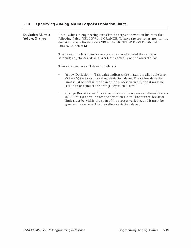
Programming Analog Alarms 8-13SIMATIC 545/555/575 Programming Reference
8.10 Specifying Analog Alarm Setpoint Deviation Limits
Enter values in engineering units for the setpoint deviation limits in thefollowing fields: YELLOW and ORANGE. To have the controller monitor thedeviation alarm limits, select YES in the MONITOR DEVIATION field.Otherwise, select NO.
The deviation alarm bands are always centered around the target orsetpoint; i.e., the deviation alarm test is actually on the control error.
There are two levels of deviation alarms.
• Yellow Deviation — This value indicates the maximum allowable error(SP – PV) that sets the yellow deviation alarm. The yellow deviationlimit must be within the span of the process variable, and it must beless than or equal to the orange deviation alarm.
• Orange Deviation — This value indicates the maximum allowable error(SP – PV) that sets the orange deviation alarm. The orange deviationlimit must be within the span of the process variable, and it must begreater than or equal to the yellow deviation alarm.
Deviation Alarms:Yellow, Orange

Programming Analog Alarms8-14 SIMATIC 545/555/575 Programming Reference
8.11 Specifying Other Analog Alarm Process Variable Alarms
Enter a value in engineering units for the rate of change alarm in the RATEOF CHANGE ALARM field. To have the controller monitor the rate ofchange, select YES in the MONITOR RATE OF CHANGE field. Otherwise,select NO.
If you program the controller to monitor the rate of change, an alarm occurswhen the rate of change of the process variable exceeds the limit specified.This is a real number in engineering units/minute that is used to set therate-of-change alarm flag.
To have the controller monitor for the broken transmitter condition, selectYES in the MONITOR BROKEN TRANSMITTER field. Otherwise,select NO.
If you program the controller to monitor for the broken transmittercondition, an alarm occurs if the raw process variable is outside the validrange designated for the PV. The valid ranges follow.
• Bipolar: –32000 to 32000
• 0% Offset: 0 to 32000
• 20% Offset: 6400 to 32000
Figure 8-4 shows the process variable in broken transmitter alarm.
Rate of ChangeAlarm
Broken TransmitterAlarm

Programming Analog Alarms 8-15SIMATIC 545/555/575 Programming Reference
ÉÉÉÉÉÉÉÉÉÉÉÉÉÉÉÉÉÉÉÉÉÉÉÉÉÉÉÉÉÉÉÉÉÉÉÉÉÉ
PVHI
PVHI + Deadband
HI/HI
HI
ÉÉÉÉÉÉÉÉÉÉÉÉÉÉÉÉÉÉÉÉÉÉÉÉÉÉÉÉÉÉÉÉÉÉÉÉÉÉ
PVLO – DeadbandPVLO
LO/LO
LO
BROKEN TRANSMITTER
ORANGEYELLOW
YELLOWORANGE
SP
PV
BROKEN TRANSMITTER
Figure 8-4 Example of Broken Transmitter Alarm

Programming Loops 9-1SIMATIC 545/555/575 Programming Reference
Chapter 9
Programming Loops
9.1 Overview 9-2. . . . . . . . . . . . . . . . . . . . . . . . . . . . . . . . . . . . . . . . . . . . . . . . . . . . . . . . . . . . . . . . . . . . . . .
9.2 Using the PID Loop Function 9-4. . . . . . . . . . . . . . . . . . . . . . . . . . . . . . . . . . . . . . . . . . . . . . . . . . . . .
9.3 Loop Algorithms 9-6. . . . . . . . . . . . . . . . . . . . . . . . . . . . . . . . . . . . . . . . . . . . . . . . . . . . . . . . . . . . . . . .
9.4 Programming Loops 9-8. . . . . . . . . . . . . . . . . . . . . . . . . . . . . . . . . . . . . . . . . . . . . . . . . . . . . . . . . . . . .
9.5 Specifying Loop PID Algorithm 9-10. . . . . . . . . . . . . . . . . . . . . . . . . . . . . . . . . . . . . . . . . . . . . . . . . . .
9.6 Specifying Loop V-Flag Address 9-11. . . . . . . . . . . . . . . . . . . . . . . . . . . . . . . . . . . . . . . . . . . . . . . . .
9.7 Specifying Loop Sample Rate 9-12. . . . . . . . . . . . . . . . . . . . . . . . . . . . . . . . . . . . . . . . . . . . . . . . . . . .
9.8 Specifying Loop Process Variable Parameters 9-13. . . . . . . . . . . . . . . . . . . . . . . . . . . . . . . . . . . .
9.9 Specifying Loop Ramp/Soak Profile 9-14. . . . . . . . . . . . . . . . . . . . . . . . . . . . . . . . . . . . . . . . . . . . . .
9.10 Specifying Loop Output Parameters 9-18. . . . . . . . . . . . . . . . . . . . . . . . . . . . . . . . . . . . . . . . . . . . . .
9.11 Specifying Loop Alarm Deadband 9-19. . . . . . . . . . . . . . . . . . . . . . . . . . . . . . . . . . . . . . . . . . . . . . .
9.12 Specifying Loop Process Variable Alarm Limits 9-20. . . . . . . . . . . . . . . . . . . . . . . . . . . . . . . . . . . .
9.13 Specifying Loop Setpoint Parameters 9-21. . . . . . . . . . . . . . . . . . . . . . . . . . . . . . . . . . . . . . . . . . . .
9.14 Specifying Loop Tuning Parameters 9-22. . . . . . . . . . . . . . . . . . . . . . . . . . . . . . . . . . . . . . . . . . . . . .
9.15 Specifying Loop Derivative Gain Limiting 9-25. . . . . . . . . . . . . . . . . . . . . . . . . . . . . . . . . . . . . . . . .
9.16 Specifying Loop Special Function Call 9-26. . . . . . . . . . . . . . . . . . . . . . . . . . . . . . . . . . . . . . . . . . .
9.17 Specifying Loop Locked Changes 9-28. . . . . . . . . . . . . . . . . . . . . . . . . . . . . . . . . . . . . . . . . . . . . . .
9.18 Specifying Loop Error Operation 9-29. . . . . . . . . . . . . . . . . . . . . . . . . . . . . . . . . . . . . . . . . . . . . . . . .
9.19 Specifying Reverse Acting Loops 9-30. . . . . . . . . . . . . . . . . . . . . . . . . . . . . . . . . . . . . . . . . . . . . . . .
9.20 Specifying Loop Setpoint Deviation Limits 9-31. . . . . . . . . . . . . . . . . . . . . . . . . . . . . . . . . . . . . . . .
9.21 Specifying Other Loop Process Variable Alarms 9-32. . . . . . . . . . . . . . . . . . . . . . . . . . . . . . . . . . .
9.22 Using SmarTune Automatic Loop Tuning (555 CPUs Only) 9-34. . . . . . . . . . . . . . . . . . . . . . . . . .

Programming Loops9-2 SIMATIC 545/555/575 Programming Reference
9.1 Overview
Process and batch control capability is provided using the controller’sproportional-integral-derivative (PID) loop functions, illustrated inFigure 9-1. When you program a loop, you can set the same eight alarmtypes used by analog alarms and described in Chapter 8.
• High-high alarm point on the process variable (PV)
• High alarm point on the PV
• Low alarm point on the PV
• Low-low alarm point on the PV
• Yellow deviation alarm point referenced to the setpoint (SP)
• Orange deviation alarm point referenced to the SP
• Rate of change alarm, for a PV changing too rapidly
• Broken transmitter, for a PV outside the designated valid range.
Setpoint
• Yellow
• Orange
Green
• Orange
• Yellow
Deviation alarms
• High-High
• High
• Low
• Low-Low
Absolute alarms
Hot waterinput
Product input
Product output
TIC601
• Broken transmitter• Rate of change
Miscellaneous alarms
Figure 9-1 Example of Loop Control

Programming Loops 9-3SIMATIC 545/555/575 Programming Reference
The high-high, high, low, and low-low alarms are fixed absolute alarms andmay correspond to warnings and shutdown limits for the process equipmentitself. The yellow and orange deviation alarms move up and down with thesetpoint and may refer to specification tolerances around the setpoint.
A PV alarm deadband is provided to minimize cycles in and out of alarm(chattering) that generate large numbers of messages when the PV hoversnear one of the alarm limits.
An option is also available to call a Special Function Program (SF program,discussed in Chapter 7) to initiate a special function calculation. TheSF program call can be scheduled on the PV, the SP, or the output.

Programming Loops9-4 SIMATIC 545/555/575 Programming Reference
9.2 Using the PID Loop Function
Loops operate in one of three states: Manual, Automatic, and Cascade. Afourth state — Loop Is Not Operating — is in effect when the controller is inProgram mode.
In Manual Mode, the loop output is not calculated by the controller but,instead, comes from the operator. While a loop is in Manual, the controllerstill monitors the Broken Transmitter, High-High, High, Low, Low-Low, andRate-of-Change alarms. The Yellow and Orange deviation alarms are notmonitored.
In Auto Mode, the controller computes the loop output. The SP for the loopcomes from either an operator interface, SF program, or from a Ramp/SoakTable. All alarms are monitored.
In Cascade Mode, the controller computes the loop output. The setpoint forthe loop comes from a user-specified location called the remote setpoint. Fortruly cascaded loops, the remote setpoint is the output of another loop. Thecontroller also allows the remote setpoint to be some other variable in thecontroller. Such loops are not truly cascaded, but the same term is used. Allalarms are monitored.
For cascaded loops, the loop for which the output is used as the setpoint foranother loop is called the outer loop. The loop that uses the output ofanother loop for its setpoint is called the inner loop. It is possible to cascadeloops more than two levels deep.
If an inner loop of a cascade is placed in Auto or Manual, then all its outerloops must be placed in Manual to prevent reset windup. Similarly, an outerloop cannot be placed in Auto until all inner loops are in Cascade. The logicto handle opening and closing of cascades is built into the controller. Briefly,this is done as follows.
• If an inner loop is switched out of Cascade, then all of its outer loopsare switched to Manual.
• A request to place an outer loop in Auto or Cascade is denied unless theinner loop is in Cascade.
If a loop is not truly cascaded, but is simply using a remote setpoint,changes to and from Cascade mode are allowed.
Manual Mode
Auto Mode
Cascade Mode

Programming Loops 9-5SIMATIC 545/555/575 Programming Reference
The controller allows the loop mode to be changed by an SF program, ladderlogic, or an operator interface device. While the loop can be requested toenter any mode from any other mode, the controller actually only performsthe following mode transitions.
MANUAL
AUTO
CASCADE
AUTO
AUTO
CASCADE
AUTO
MANUAL
The other requests (Manual Cascade and Cascade Manual) arehandled as transitions to Auto and then to the final mode as follows.
MANUAL CASCADE is done as MANUAL AUTO CASCADE
CASCADE MANUAL is done as CASCADE AUTO MANUAL
Changing LoopMode
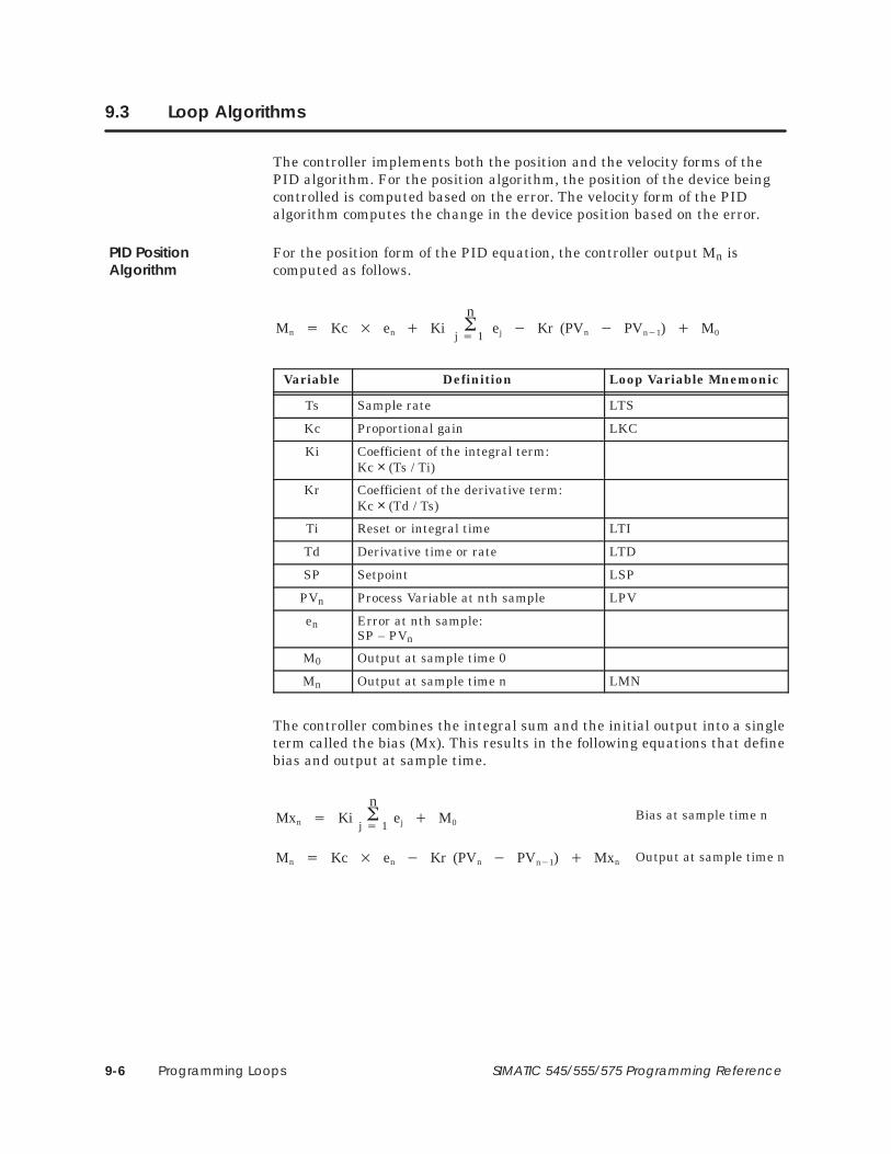
Programming Loops9-6 SIMATIC 545/555/575 Programming Reference
9.3 Loop Algorithms
The controller implements both the position and the velocity forms of thePID algorithm. For the position algorithm, the position of the device beingcontrolled is computed based on the error. The velocity form of the PIDalgorithm computes the change in the device position based on the error.
For the position form of the PID equation, the controller output Mn iscomputed as follows.
Mn � Kc � en � Kin�
j � 1ej � Kr (PVn � PVn�1) � M0
Variable Definition Loop Variable Mnemonic
Ts Sample rate LTS
Kc Proportional gain LKC
Ki Coefficient of the integral term:Kc × (Ts / Ti)
Kr Coefficient of the derivative term:Kc × (Td / Ts)
Ti Reset or integral time LTI
Td Derivative time or rate LTD
SP Setpoint LSP
PVn Process Variable at nth sample LPV
en Error at nth sample:SP – PVn
M0 Output at sample time 0
Mn Output at sample time n LMN
The controller combines the integral sum and the initial output into a singleterm called the bias (Mx). This results in the following equations that definebias and output at sample time.
Mn � Kc � en � Kr (PVn � PVn�1) � Mxn
Mxn � Kin�
j � 1ej � M0
Bias at sample time n
Output at sample time n
PID PositionAlgorithm

Programming Loops 9-7SIMATIC 545/555/575 Programming Reference
The following is an example of the computation done by the controllerduring a single sample period for a loop. The rate portion of the algorithm isusually used for special cases and is set to 0 in this example.
Variable Definition Value
Ts Sample rate 1 second
Kc Proportional gain .01
Ti Reset or integral time 1 minute
Td Derivative time or rate 0
SP Setpoint .5
PVn Process Variable for this sample .75
PVn–1 Process Variable for previous sample .77
en Error for this sample: SP – PV .5 – .75 = –.25
Mxn–1 Bias .5
Ki Coefficient of integral term: Kc × (Ts / Ti) .01 × (1s / 60s) = .00017
Kr Coefficient of derivative term: Kc × (Td / Ts) .01 × (0s / 1s) = 0
� Mn � Kc � en � Kr � (PVn � PVn�1) � MxnNew Output
New Bias� Mxn � Ki � en � Mxn�1
� Mxn � (.00017 � � (.25)) � .5� Mxn � .4999
� Mn � .49746� Mn � .01 �� (.25) � 0� (.75� .77) � .4999
The new bias is .4999 and the new output is 49.746%.
The velocity form of the PID equation is obtained by subtracting theequation at time (n–1) from the equation at time (n).
� Kc �(en � en�1) �
TsTi
� en �
TdTs
(PVn � 2PVn�1 � PVn�2 )�
�Mn � Mn � Mn�1
Variable Definition
Mn Loop output at the nth sample
Ti Reset time
Kc Proportional gain
Td Rate Time
en Error (SP–PV) at the nth sample
Ts Sample time
PVn Process Variable at the nth sample
PID VelocityAlgorithm

Programming Loops9-8 SIMATIC 545/555/575 Programming Reference
9.4 Programming Loops
Loops are referenced by a user-assigned number. The variables within eachloop are accessed by variable names assigned to each variable type. Forexample, the loop setpoint is designated by LSP; to read the value of thesetpoint for Loop 10, you read LSP10. To read the value of the setpoint lowlimit for Loop 64, you read LSPL64. Appendix A lists the loop variablenames.
When you program a loop, you display the loop programming table on yourprogramming unit and enter the data in the appropriate fields. The generalprocedure for entering loop data are listed below. Refer to the TISOFT usermanual for detailed instructions.
• Select the Loop option from the prompt line on your programmingdevice.
• Display the loop that you want to program (# 1, # 2, etc.).
• Enter the data for each field in the table.
The loop programming table is shown in Figure 9-2. The page on which afield is described is also listed. All loop parameters are stored in SpecialMemory (S-Memory) when you program the loop. The size of S-Memory isuser-configurable. Refer to the TISOFT user manual for detailedinstructions about configuring S-Memory.
PID LOOP 12
LOOP VFLAG ADDRESS:SAMPLE RATE (SECS):
SQUARE ROOT OF PV:
TITLE: XXXXXXXX
POS/VEL PID ALGORITHM:
PV IS BIPOLAR:
20% OFFSET ON PV:
LOOP OUTPUT ADDRESS:
PV ALARMS:
MONITOR LOW–LOW/HI–HI:MONITOR LOW/HIGH:
PROCESS VARIABLE ADDRESS:PV RANGE:
LOW–LOW =LOW =HIGH =
HIGH–HIGH =
LOW =HIGH =
OUTPUT IS BIPOLAR:20% OFFSET ON OUTPUT:
RAMP/SOAK PROGRAMMED:RAMP/SOAK FOR SP:
ALARM DEADBAND:
REMOTE SETPOINT:CLAMP SP LIMITS: LOW =
HIGH =
LOOP GAIN:RESET (INTEGRAL TIME):RATE (DERIVATIVE TIME):
FREEZE BIAS:
DERIVATIVE GAIN LIMITING:LIMITING COEFFICIENT:
SPECIAL CALCULATION ON:SPECIAL FUNCTION:
LOCK SETPOINT:LOCK AUTO/MANUAL:
LOCK CASCADE:
ERROR OPERATION:REVERSE ACTING
MONITOR DEVIATION:DEVIATION ALARM: YELLOW =
ORANGE =
MONITOR RATE OF CHANGE:RATE OF CHANGE ALARM:
MONITOR BROKEN TRANSMITTER:
Page 9-28
Page 9-10
Page 9-18
Page 9-13
Page 9-12
Page 9-13
Page 9-13Page 9-13
Page 9-11
Page 9-18
Page 9-14
Page 9-13
Page 9-19
Page 9-23
Page 9-21
Page 9-21
Page 9-22
Page 9-25
Page 9-26
Page 9-29Page 9-30
Page 9-31
Page 9-32
Page 9-32Page 9-20
Figure 9-2 Loop Programming Table
Loop Numbers andVariable Names
ProgrammingTables

Programming Loops 9-9SIMATIC 545/555/575 Programming Reference
A set of flags (C-Flags) stores the programming data that you enter into theProgramming Tables for the loops. The C-Flags correspond to individual bitsmaking up the two words LCFH and LCFL. LCFH contains the mostsignificant 16 bits, and LCFL contains the least significant 16 bits.Table 9-1 shows the designation for each bit in the C-Flag.
Table 9-1 Loop C-Flags (LCFH and LCFL)
Variable WordBit
FlagBit Loop Function
1 1 0 = PV scale 0% offset1 = PV scale 20% offset—only valid if PV is unipolar. See bit 21.
2 2 1 = Take square root of PV
3 3 1 = Monitor HIGH/LOW alarms
4 4 1 = Monitor HIGH-HIGH/LOW-LOW alarms
5 5 1 = Monitor yellow/orange deviation alarm
6 6 1 = Monitor rate-of-change alarm
7 7 1 = Monitor broken transmitter alarm
LCFH 8 8PID algorithm type0 = Position algorithm1 = Velocity algorithm
9 9 0 = Direct acting1 = Reverse acting
10 10 1 = Control based on error squared
11 11 1 = Control based on error deadband
12 12 1 = Auto-mode lock
13 13 1 = Cascade-mode lock
14 14 1 = Setpoint lock
15 15 0 = Output scale 0% offset1 = Output scale 20% offset—only valid if output is unipolar. See bit 20.
16 16
and
16 170 1 No special function1 0 Special function on the process variable
1and
17
0 1 No special function1 0 Special function on the process variable0 1 Special function on the setpoint1 1 Special function on the output
2 18 1 = Freeze bias when output is out-of-range
3 19 1 = RAMP/SOAK on the setpoint
LCFL 4 20 0 = Output is unipolar1 = Output is bipolar
5 21 0 = PV is unipolar1 = PV is bipolar
6 22 1 = Perform derivative gain limiting
7–16 23–32 Contains SF program number (if an SF program is scheduled to be called)
Loop C-Flags

Programming Loops9-10 SIMATIC 545/555/575 Programming Reference
9.5 Specifying Loop PID Algorithm
Select POS for the position algorithm or VEL for the velocity algorithm in thePOS/VEL PID ALGORITHM field. See Section 9.3 for a discussion of thePID algorithm.
For the position algorithm, the position of the device being controlled iscomputed based on the error. The velocity form of the PID algorithmcomputes the change in the device position based on the error.
! WARNINGControl devices can operate unpredictably causing damage to equipment.
Unpredictable operation can cause damage to equipment and/or death orserious injury to personnel.
Do not change the equation form (velocity to position, or vice versa) while thealgorithm is executing.
Pos/Vel PIDAlgorithm

Programming Loops 9-11SIMATIC 545/555/575 Programming Reference
9.6 Specifying Loop V-Flag Address
Enter an address: C, Y, V, or WY (or also G, VMM, or VMS in a 575), in theLOOP VFLAG ADDRESS field. If you select NONE, no data is written fromthe V-Flags in the loop.
The V-Flags contain the operational data for a loop. The V-Flags correspondto individual bits making up the 16-bit word LVF. Bits are defined inTable 9-2.
An entry in the LOOP VFLAG ADDRESS field causes loop data to bewritten from the V-Flags to another address. The address can be either a bit(Y or C) that allocates 15 contiguous bits, or a word (WY or V) that allocatesone word for V-Flag data.
The first three V-Flags are designated as control flags. If you create a V-Flagtable in V-Memory, for example, the controller reads these three bits in theV-Memory address and writes over the corresponding bits in the LVF word.You can change the loop mode by setting/clearing these control flags. Youcan read bits 4–15, but any changes that you make to them are overwrittenby the controller.
If you select NONE in the LOOP VFLAG ADDRESS field, no data is writtenfrom the loop V-Flags. You can still control the loop mode by using anSF program to change the control flag bits in LVF, or manually usingTISOFT to write to LVF.
Table 9-2 Loop V-Flags (LVF)
Bit Loop Function
1 1 = Go to manual mode2 1 = Go to auto mode3 1 = Go to cascade mode
4 & 54 50 0 Loop is in manual mode1 0 Loop is in auto mode0 1 Loop is in cascade mode
6 0 = Error is positive1 = Error is negative
7 1 = PV is in high-high alarm8 1 = PV is in high alarm9 1 = PV is in low alarm
10 1 = PV is in low-low alarm11 1 = PV is in yellow deviation alarm
12 1 = PV is in orange deviation alarm13 1 = PV is in rate-of-change alarm
14 1 = Broken transmitter alarm15 1 = Loop is overrunning
16 unused
Loop V-FlagAddress

Programming Loops9-12 SIMATIC 545/555/575 Programming Reference
9.7 Specifying Loop Sample Rate
Enter a time in seconds in the SAMPLE RATE field.
The sample rate determines how often deviation alarm bits and associatedmath are evaluated. Sample rates are programmable in 0.1 secondincrements, with alarms checked at least once every two seconds. Thesample rate can be any floating point number between 0.1 and 1.6772 × 10⁶
seconds.
Sample Rate

Programming Loops 9-13SIMATIC 545/555/575 Programming Reference
9.8 Specifying Loop Process Variable Parameters
Enter an address: V, WX or WY, (or also G, VMM, or VMS in a 575), or selectNONE in the PROCESS VARIABLE ADDRESS field.
A process variable must be specified for each loop. The variable may betaken from the following.
• A word input or output module — Use WX or WY address in theprogramming table.
• A location in V-Memory — Use an address in V-Memory in theprogramming table. When a special calculation is performed on aprocess variable, the result (called the computed variable) is stored inV-Memory where it is accessed by the loop.
If you select NONE, the loop does not read an address to obtain the processvariable. In this case, you can use an SF program, for example, to calculatea process variable. The result can be written to LPV for processing by theloop.
Enter the low and high values of the process variable in the following fields:PV RANGE LOW and PV RANGE HIGH.
You must specify the engineering values that correspond to the upper andlower ranges of the input span. If the span is 0 to 100%, the lower range isthe engineering value corresponding to 0 volts. If the span is 20% to 100%,then the lower range is the engineering value corresponding to 1 volt. If thespan is bipolar, the lower range is the engineering value corresponding to –5or –10 volts.
Select YES or NO to specify analog inputs as no offset, 20% offset, or bipolarin the following fields: PV IS BIPOLAR, and 20% OFFSET ON PV.
The span of the analog inputs may be either 0 to 5.0 volts, 0 to 10 volts,–10 to 10 volts, or –5 to 5 volts. The loop processing feature provides for alinear conversion over any of these process variable input spans.
A span of 0 to 5.0 volts (0 to 20.0 milliamps) is referred to as a span of 0 to100%. A span of 1.0 to 5.0 volts (4.0 to 20.0 milliamps) is referred to as aspan of 20% to 100% (20% offset on the process variable). Use the bipolaroption with a span of –10 to 10 volts or –5 to 5 volts.
Select YES or NO for the square root option in the SQUARE ROOT OF PVfield.
Select YES if the input for the process variable is from a device (such as anorifice meter) that requires a square root calculation to determine thecorrect value to use.
Process VariableAddress
PV Range Low/high
PV is Bipolar20% Offset
Square Root of PV

Programming Loops9-14 SIMATIC 545/555/575 Programming Reference
9.9 Specifying Loop Ramp/Soak Profile
The ramp/soak feature allows you to define a variation for the processvariable by specifying the time characteristics of the loop setpoint(Figure 9-3). The capability of varying the loop setpoint can be useful in anumber of processes, such as heat treating and batch cooking.
Time
Set
poin
t
Figure 9-3 Example Ramp/Soak Cycle
You can use simple ramp operations to improve some process startupprocedures. For example, the controllers do a bumpless transfer frommanual to automatic mode. This transfer holds the process at the initialstate when the mode change occurs. A two-step ramp/soak profile can thenmove the setpoint to a predefined value following the mode change, withminimal disturbance to the process.
Ramp/Soak is programmed as a set of time periods, or steps. A step can beone of three types: a ramp, a soak, or an end.
• The ramp step changes the loop setpoint linearly from its current valueto a new value, at a specified rate of change.
• The soak step holds the setpoint constant for a specified period of time.You can guarantee a soak period by entering a deadband value. Thisform of soaking ensures that the process variable is within a specifieddeadband around the setpoint for a specified period of time.
• The end step terminates a ramp/soak profile. When the programreaches an end step, the loop remains in automatic mode and holds thesetpoint constant.
You can program a status bit for each step of the ramp/soak. This bit is setto 1 when the loop is executing this step. It is reset when the loop leaves thestep. This allows for easy tracking in the RLL program.
Ramp/Soak operation can be controlled by two methods: allowing the profileto be executed automatically, or by writing values to the variables thatcontrol ramp/soak.
DefiningRamp/SoakOperation
DefiningRamp/Soak Steps
Controlling theRamp/SoakOperation

Programming Loops 9-15SIMATIC 545/555/575 Programming Reference
Automatic Whenever the loop changes from manual to automatic mode, theloop begins to execute the ramp/soak profile at the initial step (Step 1). Theloop continues to execute the profile until an end step is encountered in theprofile. At this point, the loop remains in automatic mode, and the setpointis held at the last value in the profile.
Using Ramp/Soak Number Each loop ramp/soak profile has a corresponding16-bit variable, LRSN, that contains the current step. You can monitorLRSN with an SF program and also write a step number to it with an SFprogram. The ramp/soak profile changes to the step that is currentlycontained in LRSN. Note that the step number is zero-based. LRSNcontains 0 when the profile is on step #1, 1 when the profile is on step #2,etc.
Using the Ramp/Soak Flags Each loop ramp/soak profile has a corresponding16-bit variable, LRSF, that contains operational and status information forthe profile.
When you program a ramp/soak profile, you may optionally specify aRAMP/SOAK FLAG ADDRESS. When you enter an address into this field,the controller writes the ramp/soak data from LRSF to this address. You canuse TISOFT or APT or design your RLL program to write to the first threebits at the specified address. The controller reads these bits and then writestheir status over the corresponding bits in LRSF. This enables you to changethe ramp/soak operation by setting/clearing the three bits as needed. Thecontroller ignores changes that you make in bits 4–16.
You can also monitor LRSF with an SF program and write changes to bits1–3 with an SF program.
Select YES or NO in the RAMP/SOAK FOR SP field to indicate whether aramp/soak program for the loop is to be executed. The RAMP/SOAKPROGRAMMED field is a read-only field and contains YES or NO to indicatethe creation of a ramp/soak program for the loop.
To create a ramp/soak profile for a loop, exit the Loop Programming Tableand select the Ramp/Soak Programming Table, shown in Figure 9-4.
Ramp/Soak for SP
ProgrammingRamp/Soak

Programming Loops9-16 SIMATIC 545/555/575 Programming Reference
Specifying Loop Ramp/Soak Programming (continued)
PID LOOP XXRAMP/SOAK FLAG ADDRESS: XXXXXX
STEP R/S BIT (UNITS) (UNITS/MIN) (MIN) (UNITS)STATUS SETPOINT RAMP RATE SOAK TIME DEADBAND
1234
SRSR
XXXXXX XXXXXXXXXXXXXXXXXXXXXXXXXX
XXXXXXXXXXXXXXXXXXXXXXXXXXXXXXXXXXXXXXXXXXXXXXXXXXXX
XXXXXXXXXXXXXXXXXXXXXXXXXX
XXXXXXXXXXXXXXXXXX
EXIT–F1 UP–F2 DOWN–F3 EDIT–F4
Figure 9-4 Ramp/Soak Programming Table
The first field in the table contains the ramp/soak flag address. An entry inthis field causes ramp/soak data to be written from the ramp/soak variable(LRSF) to another address, as described on Page 9-15. The address can beeither a bit (Y or C) that allocates 5 contiguous bits, or a word (WY or V)that allocates one word for ramp/soak data. The format of the bits in aramp/soak flag address correspond to the individual bits making up the16-bit word LRSF. Bits are defined in Table 9-3.
Table 9-3 Loop Ramp/Soak Flags (LRSF)
Bit Loop Function
1 1 = Restart at the first step. To restart, toggle bit off, on, then off again. The restart occurs on thetrailing edge of a square wave.
2 1 = Hold at the current step. To hold, set bit on.
3 1 = Jog to next step. To jog, set bit on. Jog occurs on the rising edge of a square wave.
4 1 = Finish. Indicates ramp/soak is completed.
5 1 = Wait. This bit is set during a soak period when the PV is not within a specified deviation fromthe SP. The loop holds the soak timer when bit 5 is set.
6 1 = Hold in progress at current step.
7–8 Unused (always returned as 0).
9–16 1 = Contains step number loop is currently executing. Step number is zero-based. Step numbercontains 0 when the Ramp/Soak is on step #1, 1 when the Ramp/Soak is on step #2, etc.
Enter an address: C, Y, V, or WY (or also G, VMM, or VMS in a 575), in theRAMP/SOAK FLAG ADDRESS field. If you select NONE, no data is writtenfrom LRSF.
The rest of the ramp/soak program consists of entering data for each step:setpoint and ramp rate for ramp steps, and soak time and deadband forsoak steps.
You can program a status bit (C or Y) for each step of the ramp/soak. Thisbit is set to 1 when the loop is executing this step. It is reset when the loopleaves the step.

Programming Loops 9-17SIMATIC 545/555/575 Programming Reference
Examples of ramp/soak profiles are shown in Figure 9-5.
STEP R/S1234
RSRS
In this example, when the loopgoes from manual to auto, it startsat step #1. At the start of ramp #1the initial setpoint is the value ofPV at mode change (bumpless).
Manual AutoTime
Setpoint goes to PV
STEP R/S1234
ENDRSR
In this example, at manual/autotransition, the loop stays in auto.JOG then starts ramp/soak. Youalso can initiate the ramp/soakprofile with an SF program that setsLRSNn to the starting step number,where n is the loop number.
5 S
Time
Setpoint goes to PV
Manual Auto
Jog
5 END
6 END
Manual AutoTime
Setpoint goes to PV
Time
Setpoint goes to PV
Manual Auto
STEP R/S1234
ENDRSR
5 S6789
ENDRSRS
END1011
Profile #1
Profile #2
Pro
file
#1P
rofil
e #2
In this example, initiation of eitherprofile is done by setting LRSNnto the start of the profile. The n isthe loop number.
LRSN set to 1
LRSN set to 6
Figure 9-5 Ramp/Soak Table Examples

Programming Loops9-18 SIMATIC 545/555/575 Programming Reference
9.10 Specifying Loop Output Parameters
Enter an address: WY or V (or also G, VMM, or VMS in a 575), in the LOOPOUTPUT ADDRESS field. Select NONE when you do not want the loop towrite the output to an address.
Use the LOOP OUTPUT ADDRESS field to specify the address into whichthe loop writes the value of the output. You can select NONE in situations,such as for cascaded loops, in which the outer loop does not require anoutput address.
Select YES or NO in the OUTPUT IS BIPOLAR field. If you select YES, theoutput range is –32000 to +32000.
Select YES or NO in the 20% OFFSET ON OUTPUT field. If you select YES,the output range is +6400 to +32000.
If you select NO for both fields (no 20% offset and output is not bipolar) thenthe output range is 0–32000.
Loop OutputAddress
Output is Bipolar
20% Offset onOutput

Programming Loops 9-19SIMATIC 545/555/575 Programming Reference
9.11 Specifying Loop Alarm Deadband
Enter a value in engineering units for the alarm deadband in the ALARMDEADBAND field.
When you specify an alarm deadband, the controller can provide hysteresison all alarms (except the rate of change alarm) to prevent them fromchattering when the process variable is near one of the alarm limits. Theloop does not exit the alarm condition until the process variable has comeinside the alarm limit minus the deadband. This is shown graphically inFigure 9-6.
The range for the deadband (LADB) is 0.0 ≤ LADB ≤ (LPVH – LPVL), whereLPVH and LPVL are the process variable high and low limits, respectively.Typically, the deadband ranges from 0.2% to 5% of the span.
100% PV
SCALE
ALARM
DEADBAND
SP
∆
∆
∆
∆
0% PV
SCALE
ALARM
DEADBAND
Y
Y
0
0
(LOW) (LOW) (LOW) (HIGH) (HIGH) (HIGH)YELLOW ORANGE YELLOW YELLOW ORANGE YELLOW
Figure 9-6 Example of Alarm Deadband For Loops
Alarm Deadband

Programming Loops9-20 SIMATIC 545/555/575 Programming Reference
9.12 Specifying Loop Process Variable Alarm Limits
Enter values in engineering units for the process variable alarm limits inthe following fields: LOW-LOW, LOW, HIGH, and HIGH-HIGH. To have thecontroller monitor the alarm limits, select YES in the following fields:MONITOR LOW-LOW/HIGH-HIGH and MONITOR LOW/HIGH.Otherwise, select NO.
The high-high and low-low alarms can be entered as values requiringcritical actions, while the high and low can be set at values requiringremedial measures. The range of possible values that can be used is givenbelow.
• Low-low alarm — real number in engineering units; must be less thanor equal to low alarm value and greater than or equal to low range ofPV.
• Low alarm — real number in engineering units; must be less than orequal to high alarm value of PV.
• High alarm — real number in engineering units; must be less than orequal to high high alarm value of PV.
• High-high alarm — real number in engineering units; must be greaterthan or equal to high alarm value and less than or equal to high rangeof PV.
PV AlarmsLow-low, Low-high,High-high

Programming Loops 9-21SIMATIC 545/555/575 Programming Reference
9.13 Specifying Loop Setpoint Parameters
Enter an address: V, K, WX, WY, or LMN (or also G, VMM, or VMS in a 575), inthe REMOTE SETPOINT field. Select NONE if there is no remote setpoint.
If you want to use a value external to the loop for the setpoint, you specifythe address for this value in the REMOTE SETPOINT field. For example,you can use data from a field transmitter for the setpoint by using a WXaddress for the transmitter input. Then, specify this WX address in theREMOTE SETPOINT field.
If you want to use a remote setpoint for either cascading loops or performinga special function on the setpoint outside of a loop, you must specify thecascade mode.
If the controller is to control the mode of the inner loop in a cascadeconfiguration, the remote setpoint for the inner loop must be specified asLMNn (the output of the outer loop n ).
Enter values for the setpoint limits in the CLAMP SP LIMITS field. SelectNONE if there are no limits, and if zeroes are placed in the high and lowfields.
Remote Setpoint
Clamp SP Limits

Programming Loops9-22 SIMATIC 545/555/575 Programming Reference
9.14 Specifying Loop Tuning Parameters
Enter values for the loop tuning constants in the following fields: LOOPGAIN, RESET (INTEGRAL TIME), and RATE (DERIVATIVE TIME).
It is not always necessary (or even desirable) to have full three-mode PIDcontrol of a loop. Parts of the PID equation can be eliminated by choosingappropriate values for the gain (Kc), reset (Ti), and rate (Td) thus, yielding aP, PI, PD, I, and even an ID or a D loop.
The contribution to the output due to integral action can be eliminated bysetting Ti = infinity. When this is done, you can manually control the biasterm (Mx) to eliminate any steady-state offset.
The contribution to the output due to derivative action can be eliminated bysetting Td = 0.
The contribution to the output due to the proportional term can beeliminated by setting Kc = 0. Since Kc is also normally a multiplier of theintegral coefficient (Ki) and the derivative coefficient (Kr), the controllermakes the computation of these values conditional on the value of Kc asfollows.
� Kc � (Ts�Ti)� Ts�Ti
if Kc � 0.
if Kc � 0.
if Kc � 0.
if Kc � 0.� Kc � (Td�Ts)� Td�Ts
Ki
Kr
(for I or ID control)
(for ID or D control)
The units and range of each of the tuning constants follow:
Coefficient Unit Range
Proportional Gain, Kc %/% 0.01–100.00
Reset (Integral Time)Time, Ti minutes 0 < Ti ≤ Infinity
Derivative Time, Td minutes 0 ≤ Td < Infinity
Loop Gain, Reset,Rate
Removing IntegralAction
RemovingDerivative Action
RemovingProportional Action

Programming Loops 9-23SIMATIC 545/555/575 Programming Reference
Select YES in the FREEZE BIAS field to have the bias frozen when outputgoes out of range. Select NO to have the bias adjusted when output goes outof range.
If you select YES for the FREEZE BIAS option, the controller stops changingthe bias Mx whenever the computed output M goes outside the interval[0.0, 1.0]. When this option is selected, the computation of the new outputMn and bias Mx is done as follows.
Calculated Bias
Calculated Output
New Output
New Bias
Mx
M
Mn
Mxn
� Ki � en � Mxn�1
� Kc � en � Kr �PVn � PV(n�1)
� Mx
� 0.0
� M
� 1.0
if M � 0.0
if 0.0 � M � 1.0
if M � 1.0
if 0.0 � M � 1.0� Mx
� Mxn�1 otherwise
In this example, it is unlikely that the bias will go all the way to zero. Whenthe PV does begin to come down, the loop begins to open the valve soonerthan it would have if the bias had been allowed to go all the way to zero.This action has the effect of lessening the amount of overshoot.
Figure 9-7 illustrates the results of freezing the bias after a disturbance.
100%
Disturbance
Bias — Frozen
Actual output (100%)
Calculated output
Time
Span
Calculated outputbegins to returnto required level.
Actual outputbegins to returnto required level.
Figure 9-7 Loop Response to the Freeze Bias Option
Freeze Bias

Programming Loops9-24 SIMATIC 545/555/575 Programming Reference
Specifying Loop Tuning Parameters (continued)
If you select NO for the FREEZE BIAS option, the controller makes thecomputation of the bias term conditional on the computation of the outputas follows.
Calculated Bias
Calculated Output
New Output
New Bias
Mx
M
Mn
Mxn
� Ki � en � Mxn�1
� Kc � en � Kr �PVn � PV(n�1)
� Mx
� 0.0
� M
� 1.0
if M � 0.0
if 0.0 � M � 1.0
if M � 1.0
if 0.0 � M � 1.0� Mx
� Mn � �Kc � en � Kr �PVn � PVn�1 otherwise
With this method, the valve begins to close as soon as the process variablebegins moving back toward the setpoint. If the loop is properly tuned,overshoot can be eliminated entirely, assuming that the setpoint is notchanging. If the output goes out of range due to a setpoint change, then theloop probably oscillates because the bias term must stabilize again.
The choice of whether to use the default loop action or to freeze the biasdepends on the application.
Figure 9-8 illustrates the results of adjusting the bias after a disturbance.
100%
Disturbance
Time
Span
Calculated output, before bias adjustment
Actual output (100%)
Bias - adjusted
Actual output begins toreturn to required level.
Figure 9-8 Loop Response to the Adjust Bias Option
Adjust Bias

Programming Loops 9-25SIMATIC 545/555/575 Programming Reference
9.15 Specifying Loop Derivative Gain Limiting
Enter a value for the derivative gain limiting coefficient in the LIMITINGCOEFFICIENT field. Select YES or NO in the DERIVATIVE GAINLIMITING field to have derivative gain limiting done. If you specify NOthen derivative gain limiting is not done, even if a value is entered in thefield. Typically, Kd should be in the range of 10 to 20.
In the standard PID algorithm, the algorithm responds excessively toprocess noise if the coefficient of the derivative term (Td/Ts) is significantlyabove the 10 to 20 range. This causes disturbances that lead to erraticbehavior of the process.
To solve this problem, the controller allows you the option of selecting aderivative gain limiting coefficient (Kd). Using this coefficient enables theProcess Variable to be filtered with a time constant that is proportional tothe derivative time (Td). The PID equations with the derivative gainlimiting coefficient follow.
• Position Algorithm.
Yn
Mx
M
� Yn�1 �
TsTs � (Td�Kd)
�
�PVn � Yn�1�
� Ki � en � Mxn�1
� Kc � en � Kr (Yn � Yn�1) � Mx
• Velocity Algorithm.
Yn
�Mn
� Yn�1 �
TsTs � (Td�Kd)
�
�PVn � Yn�1�
� Kc � (en � en�1) � Ki � en � Kr � (Yn � 2 � Yn�1 � Y
Variable Definition Variable Definition
Mn Loop output Mx Bias (Mx is the initial valveposition
Kc Proportional gain Td Rate time
en Error (SP – PV) Ki Integral gain
Ts Sample time Kd Derivative gain-limitingcoefficient
PVn Process variable
Limiting Coefficient

Programming Loops9-26 SIMATIC 545/555/575 Programming Reference
9.16 Specifying Loop Special Function Call
Enter an SF program number in the SPECIAL FUNCTION field and selecta variable (PROCESS VARIABLE, SETPOINT, or OUTPUT) in the SPECIALCALCULATION ON field.
If you enter an SF program number in the SPECIAL FUNCTION field butselect NONE for the SPECIAL CALCULATION ON field, the SF program isnot called for execution.
You can program the loop to call an SF program to do a calculation on anyconstant, variable, or I/O point. You can schedule the SF program call to bemade when the process variable, setpoint, or output is read.
NOTE: With PowerMath CPUs, an SF program can be compiled orinterpreted. If the SF program is compiled, it executes to completion whenthe loop calls it. If the SF program is interpreted, it is initiated when theloop calls it. While an interpreted SF program is executing, a higher priorityprocess on its queue may interrupt it on any SF statement boundary.
When the loop is in AUTO or CASCADE mode, the SF program calls at thesample rate and T2 always equals 2. When the loop is in MANUAL mode,the SF program does not call for execution.
When the loop is in AUTO, CASCADE, or MANUAL mode, the SF programeither executes every 2.0 sec or at the sample rate, whichever is less. The SFprogram is called at least every 2 seconds to monitor/activate the PV alarmsassociated with the loop, even though loop calculations are not being done.
In the case of a loop sample time greater than 2.0 seconds, the SF programis called at a 2.0 second interval, and T2 equals 3, indicating that the SFwas called on PV. This allows for PV manipulation before PV alarmingoccurs in the loop. When it is time to do the loop calculation, T2 equals 2 toindicate that the loop calculation is about to begin. This allows formanipulation of both PV and setpoint before the loop calculation is done. Ifthe loop sample time is less than 2.0 seconds, T2 always equal 2.
NOTE: SF programs called on PV or SP are executed after PV and SP havebeen determined by the loop, but before any processing is done based on thevalues obtained. This allows SF programs to manipulate the PV or SPbefore the loop uses them for output adjustments.
SpecialCalculation/Special Function
CalculationScheduled onSetpoint
CalculationScheduled onProcess Variable

Programming Loops 9-27SIMATIC 545/555/575 Programming Reference
When a loop with a sample time of less than than 2.0 seconds calls an SFprogram, the SF program is actually called twice for every loop calculation.
• After PV and SP are determined, the SF program is called on SP(T2 = 2). This call allows for PV and SP manipulation before PValarming and loop calculations are run. The loop calculation is thenperformed and the resultant output value is placed in LMN.
• The SF program is then called on output (T2 = 5) to allow formanipulation of the loop output value in LMN before this value iswritten to the loop output address.
If the sample time of the loop is greater than 2.0 seconds, the same applies,except that the SF program is called at least every 2.0 seconds, and T2 = 3 ifit is not time to do a loop calculation. (Refer to Section 7.6 for a descriptionof T-Memory.)
CalculationScheduled onOutput

Programming Loops9-28 SIMATIC 545/555/575 Programming Reference
9.17 Specifying Loop Locked Changes
Select YES or NO for the lock option in the following fields: LOCKSETPOINT, LOCK AUTO/MANUAL, LOCK CASCADE.
The loop programming table provides the option of locking setpoint,auto/manual, or cascade by answering YES in the fields for the optiondesired. Operator interface devices use the lock bits; these bits are not usedby the controller.
Lock Setpoint,Auto/Manual,Cascade

Programming Loops 9-29SIMATIC 545/555/575 Programming Reference
9.18 Specifying Loop Error Operation
Select SQUARED or DEADBAND in the ERROR OPERATION field. The ErrorSquared and the Error Deadband options are mutually exclusive. SelectNONE if there is to be no calculation on the error value.
In calculating the control equation, the controller uses an error value equalto, or less, than 1.0 (% of PV span over 100). Therefore, selecting errorsquared gives a lower gain for a higher error. The control equation witherror squared is based on signed error squared, instead of the error alone.
For example, an error of 0.5 squared sets the error term in the controlequation to 0.25. Since this means the control equation is less responsive tothe process variable, error squared is best used with PH control types ofapplications. When error squared control is selected, the error is calculatedas follows.
e
en
� SP � PVn
� e � abs ( e)
Since en � e, a loop using the error squared is less responsive than a loopusing just the error. In fact, the smaller the error, the less responsive theloop.
To implement a high gain for large errors, and no gain for small errors,incorporate an error deadband. When error deadband is selected, thecontroller does not take any action on the output if the process variable iswithin the yellow deviation limits.
When error deadband control is selected, the error is calculated as:
e
en
� SP � PVn
� 0
� e � YDEV
� e � YDEV
if e � YDEV
if e � � YDEV
if abs (e) � YDEV
YDEV is the yellow deviation alarm limit.
If you select the NONE option, no calculation is done on the error value. Theerror is determined by the following equation.
en � SP � PVn
Error Operation
Error Deadband
No ErrorCalculation

Programming Loops9-30 SIMATIC 545/555/575 Programming Reference
9.19 Specifying Reverse Acting Loops
Select YES for a reverse-acting loop in the REVERSE ACTING field. SelectNO for a direct-acting loop.
The controller can give the gain output as positive or negative and the loopis defined as direct- or reverse-acting (Figure 9-9).
A direct-acting loop is defined to have a positive gain; i.e., a positive changein error (SP–PV) results in a positive change in the output from thecontroller. The value of the output signal increases as the value of the errorincreases. Note that different manufacturers define forward- andreverse-acting controller responses in different ways.
A reverse-acting loop is defined to have a negative gain; i.e., a positivechange in error (SP–PV) results in a negative change in the output from thecontroller. The value of the output signal decreases as the value of the errorincreases.
Steam
Trap
Temperature controller
Return
Process requiring reverse acting control.
Process requiring direct acting control.
Temperature controller
Air-to-open valve
Air-to-open valve
Cooling water
Figure 9-9 Examples of Direct- and Reverse-Acting Control
Reverse Acting
Direct-Acting Loop
Reverse-ActingLoop

Programming Loops 9-31SIMATIC 545/555/575 Programming Reference
9.20 Specifying Loop Setpoint Deviation Limits
Enter values in engineering units for the setpoint deviation limits in thefields: YELLOW and ORANGE. To have the controller monitor the deviationalarm limits, select YES in the MONITOR DEVIATION field. Otherwise,select NO.
The deviation alarm bands are always centered around the setpoint; i.e., thedeviation alarm test is actually on the control error. Therefore, they are onlyprocessed while the loop is in the auto or cascade mode.
There are two levels of deviation alarms.
• Yellow Deviation — This value indicates the maximum allowable error(SP – PV) that sets the yellow deviation alarm. The yellow deviationlimit must be within the span of the process variable, and it must beless than or equal to the orange deviation alarm.
• Orange Deviation — This value indicates the maximum allowable error(SP – PV) that sets the orange deviation alarm. The orange deviationlimit must be within the span of the process variable, and it must begreater than or equal to the yellow deviation alarm.
Deviation AlarmsYellow, Orange

Programming Loops9-32 SIMATIC 545/555/575 Programming Reference
9.21 Specifying Other Loop Process Variable Alarms
Enter a value in engineering units for the rate of change alarm in the RATEOF CHANGE ALARM field. To have the controller monitor the rate ofchange, select YES in the MONITOR RATE OF CHANGE field. Otherwise,select NO.
If you program the controller to monitor the rate of change, an alarm occurswhen the rate of change of the process variable exceeds the limit specified.This is a real number in engineering units/minute that is used to set therate-of-change alarm flag.
To have the controller monitor for the broken transmitter condition, selectYES in the MONITOR BROKEN TRANSMITTER field. Otherwise, select NO.
If you program the controller to monitor for the broken transmittercondition, an alarm occurs if the raw process variable is outside the validrange designated for the PV. The valid ranges follow.
• Bipolar : –32000 to 32000
• 0% Offset : 0 to 32000
• 20% Offset : 6400 to 32000
Figure 9-10 shows the process variable in broken transmitter alarm.
Rate of ChangeAlarm
Broken TransmitterAlarm

Programming Loops 9-33SIMATIC 545/555/575 Programming Reference
ÉÉÉÉÉÉÉÉÉÉÉÉÉÉÉÉÉÉÉÉÉÉÉÉÉÉÉÉÉÉÉÉÉÉÉÉÉÉ
PVHI
PVHI + Deadband
HI/HI
HI
ÉÉÉÉÉÉÉÉÉÉÉÉÉÉÉÉÉÉÉÉÉÉÉÉÉÉÉÉÉÉÉÉÉÉÉÉÉÉ
PVLO – DeadbandPVLO
LO/LO
LO
BROKEN TRANSMITTER
ORANGEYELLOW
YELLOWORANGE
SP
PV
BROKEN TRANSMITTER
Figure 9-10 Example of Broken Transmitter Alarm

Programming Loops9-34 SIMATIC 545/555/575 Programming Reference
9.22 Using SmarTune Automatic Loop Tuning (555 CPUs Only)
SmarTune� is an automatic PID loop tuning process that is built into thenew SIMATIC 555 CPUs with Release 5.0 or greater firmware. You mustalso use SoftShop 505 for Windows programming software, Release 2.2 orgreater to use the SmarTune loop tuning feature. SmarTune is notsupported by TISOFT. For complete information on how to configureSmarTune, refer to your SoftShop user manual.
SmarTune temporarily puts a loop into manual mode. It makes a selectablechange to a loop’s output (Mn) to cause a process variable (PV) movementtoward the center of the PV span. Resultant PV changes are sampled. Aftersampling criteria is met, sampled values are used to calculate theoreticaloptimum gain (Kc), reset (Ti), and rate (Td). Theoretical optimums areconverted to pragmatic optimums by a heuristic and assigned. The loop isswitched to its previous mode and its previous set point (SP) is re-assigned.
Only one SmarTune session is in progress at a time. Other requests areautomatically queued. A SmarTune queue can hold all possible entries.Each entry is processed in the order requested. A session may be aborted atany time, whether in progress or queued.
A SmarTune configuration consists of 33 parameters for each loop, whichare either value parameters or variable parameters. These parametersallow you to automate loop tuning as desired. For example, you can choosewhether or not to automatically load the new tuning parameters directlyinto the referenced loop.
NOTE: SmarTune can only be used for position or temperature loops. It isnot applicable to velocity loops.
The following section describes, in general terms, the PID autotune processfor a temperature control loop.
! CAUTIONSmarTune should not be used if a process might experience harmful effects asa result of arbitrary M n assignment. During a tuning session, M n values areassigned in such a way as to determine the frequency response of a process.
The tuning process may result in process product that does not meet requiredstandards. This product may need to be purged before and/or after a tuningsession.
Ensure that your process is designed to handle the results of loop tuning.
Overview ofSmarTune

Programming Loops 9-35SIMATIC 545/555/575 Programming Reference
The PID algorithm consists of three components: the Proportional, theIntegral (Reset), and the Derivative (Rate). Each component impacts theoutput to address the varied characteristics of the process variable. The PIDexpression is:
Output = P_Gain * Error + I_Gain * ��
�
Error (dt) + D_Gain * Error (d / dt)
where,Error = Setpoint – Process VariableP_Gain = Proportional GainI_Gain = Integral GainD_Gain = Derivative Gain
Temperature control with PID has two regions of operation, the proportionalband, and the saturated region. The proportional band is the region aboveand below the setpoint where the controller output is less than 100%. Theheat or cooling output is time proportioned as determined by the PIDoutput. The proportional gain value determines the proportional band.
A typical proportional band might be around ±30�F for a given machinerytemperature control, as shown in Figure 9-11. For example, with a setpointof 300�F, a proportional band of ±30�F would equate to the region between270�F and 330�F, where the controller would be in the proportional band.Outside of this region, on either side, is the saturated region where thecontroller output would be 100%, which equates to 100% heating or cooling.
330�F
300�F
270�F
100% Output
Setpoint
100% Output
Proportional Band
Output = Proportional Gain * Error
Figure 9-11 Proportional Band
The Loop TuningProcess Equation
The ProportionalComponent

Programming Loops9-36 SIMATIC 545/555/575 Programming Reference
Using SmarTune Automatic Loop Tuning (555 CPUs Only), (continued)
A temperature controller using only the proportional component of the PIDexpression may experience a steady state error, as shown in Figure 9-12.This error is induced by thermal loading on a temperature zone. As thethermal loading on a temperature zone increases, the magnitude of thesteady state error is increased.
330�F
300�F
270�F
Setpoint Steady state error
Figure 9-12 Steady State Error
Thermal loading is induced by energy losses to the surroundings, conductionthrough the machine, as well as the process. A proportional-only controllercan resolve this error only to a limited degree.
The integral term of the PID expression provides a means to eliminate theerror in the proportional band. This term is defined as the Error integratedover time. Thus, in the case of the steady state error, the output would beincreased (or decreased depending on the sign of the Error) over time. Theamount of the integral adjustment is determined by the magnitude of theError, and the Integral gain. Excessive Integral gain would cause anoscillation about the setpoint. Likewise, minimal Integral gain would notreduce the Error in a timely manner and be ineffective.
The IntegralComponent

Programming Loops 9-37SIMATIC 545/555/575 Programming Reference
The Derivative term of the PID expression provides a mathematical meansfor limiting the rate of change of the process variable. As the rate of changebecomes larger, the derivative term reduces the output, resulting in thereduction of the rate of change of the process variable. The Derivative gaindefines the magnitude of the output reduction as a function of the rate ofchange of the process variable. Excessive Derivative gain would result in anundesirable output oscillation as the controller continues to eliminate theError.
When the PID gains are set appropriately, the resulting process variablecurve would take on the “ideal curve” appearance, as shown in Figure 9-13.
330�F
300�F
270�F
Setpoint
Figure 9-13 Ideal Process Variable Curve
Many factors affect the process variable curve. These factors may take theprocess beyond where the controller can create the ideal curve. It is thefunction of the PID SmarTune utility to determine the optimum PID gainvalues to achieve a response as close to the ideal curve as possible.
Essentially, the SmarTune utility creates a disturbance by initiating a stepincrease of the PID output. Process variable samples are collected as thisincrease in output precipitates a change in the process variable. When thesample period is complete, the data collection is analyzed for time lag,gradient, overshoot, steady state error, and oscillation. Using a frequencyanalysis method, the optimum PID gain values are determined. You canchoose to accept the newly calculated gain values, or keep the present PIDgain settings.
The DerivativeComponent

Programming Loops9-38 SIMATIC 545/555/575 Programming Reference
Using SmarTune Automatic Loop Tuning (555 CPUs Only), (continued)
The SmarTune variable parameters are listed and described in this section.Start Variable is the only variable that must be specified. It names adiscrete variable used to activate a SmarTune session. The others may benull.
Variable parameters provide the coupling between a PLC program andSmarTune. If only Start Variable is specified, no program coupling isneeded; a session begins when Start Variable becomes true and ends with aloop changing back to its previous mode and SP. Since coupling is done withvariables, any program type may be used to monitor and control SmarTune(relay ladder logic, SFPGM, or SFSUB).
Table 9-4 lists the variable parameters used by SmarTune. The followingparagraphs describe the parameters.
Table 9-4 Variable Parameters
Name Type Allowable Variable Types
Start Variable discrete X Y C WX WY V
Abort Variable discrete X Y C WX WY V
Ack Variable discrete Y C WY V
SmarTune Restart discrete X Y C WX WY V
Status Variable word WY V
PIN Variable word WX WY V
Previous Mode word V
Previous SP real V
Previous Output word V
Previous Gain real V
Previous Reset real V
Previous Rate real V
Calculated Gain real V
Calculated Reset real V
Calculated Rate real V
VariableParameters

Programming Loops 9-39SIMATIC 545/555/575 Programming Reference
Start Variable, Abort Variable, Ack Variable
These three discrete variables allow easy activation/deactivation via an RLLprogram, as shown in Figure 9-14.
StartVariable
RST
StartVariable
AbortVariable
AckVariable
RST
AbortVariable
Figure 9-14 Example of Activation/Deactivation of Auto Tuning Process
These variables could just as easily be manipulated with IF, IMATH orMATH statements in an SFPGM or SFSUB. Allowed discrete variablesinclude bits in a V-memory word.
• When Start Variable transitions from a false to a true, a SmarTunesession is activated.
• When Abort Variable is true, a SmarTune session is deactivated.
• If both are true, a session is deactivated, and Start Variable musttransition before a session will be activated.
• If a SmarTune session is already queued or in progress, Start Variabletransitions are ignored.
Ack Variable acknowledges that SmarTune has detected that Start Variableor Abort Variable is true. It is used to synchronize Start Variable and AbortVariable program logic with SmarTune. If not used, Start Variable andAbortVariable should remain true for a relatively large amount of time.What constitutes a large amount of time depends on program size and timeslice assignments. See the discussion for Activation Time Slice for furtherguidance.
SmarTune Restart
If this discrete variable is true, then SmarTune is restarted completely.SmarTune will act as if a run–program–run transition occurred. IfSmarTune Restart is specified in more than one configuration, all are testedfor true and acted upon.

Programming Loops9-40 SIMATIC 545/555/575 Programming Reference
Using SmarTune Automatic Loop Tuning (555 CPUs Only), (continued)
Status Variable
This word variable reports on the current state of a session. Three bits areused in the word to allow easy use by an RLL program. Bit 2 is set when aSmarTune session is completed, with or without errors or warnings. If bit 3is also set then an error was detected. Similarly, if bit 4 is set, then awarning condition occurred. If only bit 2 is set, then a SmarTune sessioncompleted with no errors or warnings. See Table 9-5 for a complete listing.Note that entries with x’s represent ranges of values.
PIN Variable
PIN Variable and PIN are provided to force a two-step procedure to befollowed before a loop is tuned. To use this feature, PIN Variable and PINmust both be set. If PIN Variable is a null or PIN is zero, then SmarTuneactivation is a one-step procedure dependent only on Start Variable. If bothare specified, then PIN Variable must equal PIN or a SmarTune session willnot be started or queued.
Previous Mode
If Previous Mode is used, it is set by SmarTune to a value which will switcha loop to its pre-session mode when written to a loop’s LVF. This wasconceived for use when Automatic Download has been configured as false,but may be used for other purposes. If Automatic Download is false, a loopis left in manual mode with its output set to Safe Output when a tuningsession has completed. When AutomaticDownload is true, a loop is switchedback to its previous mode and is assigned its previous SP on completion.
Previous SP, Previous Output, Previous Gain, Previous Reset,Previous Rate
You can use these five parameters to record the prior SP, Mn, Kc, Ti, and Tdof a loop before a SmarTune session starts. See Previous Mode for a shortdiscussion on why they would be configured.
Calculated Gain, Calculated Reset, Calculated Rate
You can use these three variables to record the tuning values calculated bySmarTune. See Previous Mode for a short discussion on why they would beconfigured.

Programming Loops 9-41SIMATIC 545/555/575 Programming Reference
Table 9-5 lists the loop tuning errors written to the Status Variable word.
Table 9-5 Status Code Bit Values
qponmlkjihgfwecr
r — reserved (always 0)c — complete (operation is complete)e — error (error condition detected)w — warning (warning condition detected)f–>q meanings dependent on c–e–w bitsx — irrelevant for this condition
rcew fghi jklm nopq Description
0000 xxxx xxxx xxxx SmarTune in progress or not active
0000 0000 0000 0000 Not active
0000 0000 0000 1000 Waiting in SmarTune queue
0000 0000 0001 0000 Waiting for Loop to enter manual mode
0000 0000 0001 1000 Wait 1 (PV value stabilize)
0000 0000 0010 0000 Wait 2 (PV value stabilize)
0000 0000 0010 1000 Wait 3 (PV value stabilize)
0000 0000 0011 0000 Calculating Tuning Parameters
0100 0000 0000 0000 SmarTune complete with no errors or warnings
0101 xxxx xxxx xxxx SmarTune complete with warning(s)
0101 xxxx xxxx xx01 Data questionable, tuning may not be reliable
0101 xxxx xxxx xx10 Data questionable, tuning is not reliable
0101 xxxx xxx0 01xx Sample interval too large for optimal tuning
0101 xxxx xxx0 10xx Small PV change; Step too small?
0101 xxxx xxx0 11xx PV near span low; Range marginal?
0101 xxxx xxx1 00xx PV near span high; Range marginal?
0101 xxxx xxx1 01xx Small output change; Step too small?
0101 xxxx xxx1 10xx Output near span low; Range marginal?
0101 xxxx xxx1 11xx Output near span high; Range marginal?
0101 xxxx xx1x xxxx PV changes before output; Noisy signal?
0101 xxxx x1xx xxxx PV changes inconsistent with output; Noisy signal?
0101 xxxx 1xxx xxxx Gain clamped to high/low limit
0101 xxx1 xxxx xxxx Reset clamped to high/low limit
0101 xx1x xxxx xxxx Rate clamped to high/low limit
0110 xxxx xxxx xxxx SmarTune complete with error(s)
0110 0000 0000 0000 Unanticipated error

Programming Loops9-42 SIMATIC 545/555/575 Programming Reference
Using SmarTune Automatic Loop Tuning (555 CPUs Only), (continued)
Table 9-5 Status Code Bit Values (continued)
rcew fghi jklm nopq Description
0110 xxxx xxxx 0001 PIN mismatch
0110 xxxx xxxx 0010 Loop would not go to Manual Mode
0110 xxxx xxxx 0011 Loop not completely under SmarTune control
0110 xxxx xxxx 0100 SmarTune timeout (Maximum time exceeded)
0110 xxxx xxxx 0101 Not enough free memory
0110 xxxx xxxx 0110 Out of required system resources
0110 xxxx xxxx 0111 PV greater than high stop
0110 xxxx xxxx 1000 PV lower than low stop
0110 xxxx xxxx 1001 PV change too small
0110 xxxx xxxx 1010 Operation aborted
0110 xxxx xx01 xxxx Sample interval (LTS) range error (allowed range: 0.1 ms to 2 hours)
0110 xxxx xx10 xxxx PV (LPV) or output (LMN) range error (range < 0.00001)
0110 xxxx xx11 xxxx Sample size too small (probably would never happen)size < 33 (increase STEP or decrease NOISE)
0110 xxx0 01xx xxxx PV/output inconsistent 1; Noisy PV/output signal?
0110 xxx0 10xx xxxx PV/output inconsistent 2; Noisy PV/output signal?
0110 xxx0 11xx xxxx PV/output inconsistent 3; Noisy PV/output signal?
0110 xxx1 00xx xxxx PV/output inconsistent 4; Noisy PV/output signal?
0110 xxx1 01xx xxxx PV/output inconsistent 5; Noisy PV/output signal?

Programming Loops 9-43SIMATIC 545/555/575 Programming Reference
Table 9-6 lists the value parameters used by SmarTune, with the defaultvalues and the ranges possible for each.
Table 9-6 Value Parameters
Name Default Value Range
Max Time 30.0 minutes 0 to 71582 minutes (maximum isabout 49 days)
Noise Band 0.005 of PV range PV range (engineering units)
Step Change 0.07 of PV range PV range (engineering units)
Wait Time 0.5 minutes same as Max Time
PIN 0 (PIN not required) 0 to 32767
Automatic Download TRUE TRUE/FALSE
Calculate Derivative FALSE TRUE/FALSE
Safe Output use Previous Output Previous Output, 0 to 32000
High Stop 0.8 of PV range PV range (engineering units)
Low Stop 0.2 of PV range PV range (engineering units)
Largest Gain 8000000.0 %/% real
Smallest Gain 0.0000008 %/% real
Largest Reset 8000000.0 minutes real
Smallest Reset 0.0000008 minutes real
Largest Rate 8000000.0 minutes real
Smallest Rate 0.0000008 minutes real
Activation Time Slice 0 0:not configured here, 1 to 255 ms
Calculation Time Slice 0 0:not configured here, 1 to 255 ms
Max Time
Max Time is a time in minutes. When a SmarTune session is started, atimer is set to this value. If that timer expires before the session hascompleted, the session is aborted with an error (see Table 9-5).
Noise Band
When electrical signals are converted to values, they vary randomly byinsignificant amounts. An insignificant amount is application dependent.Noise Band gives a value in engineering units denoting the boundarybetween a significant and an insignificant change. If a PV value differs froma prior value by a Noise Band or greater amount, then a PV change hasoccurred. Otherwise the PV is considered unchanged. Some errors andwarnings in Table 9-5 could be caused by an incorrect Noise Band setting. Acorrect setting may be calculated from hardware specifications, ordetermined by experiment and observation, or both.
Value Parameters

Programming Loops9-44 SIMATIC 545/555/575 Programming Reference
Using SmarTune Automatic Loop Tuning (555 CPUs Only), (continued)
Step Change
SmarTune works best with a PV change of about 7%. This change isaccomplished by changing Mn proportional to the ratio betweenStep Change and PV span. Step Change is specified in engineering units ofthe PV. If a PV span is 0 to 60 degrees and Step Change is 5 degrees, thenMn would be changed by about 2667 (5/60 * 32000). Due to round-off error,the actual value might be slightly different. This example is based on an Mnspan of 0 to 32000. If a 20% offset on output is selected for a loop, an Mnchange of about 2133 (Mn span of 25600) would be accomplished. SeeTable 9-5 for possible warnings and errors associated with Step Change.
Wait Time
The SmarTune sample algorithm looks for a PV to change by Step Changeor to quit changing. Wait Time is required to determine when a PV has quitchanging. If a PV value does not change by a Noise Band amount within aWait Time period, then it has stopped changing.
PIN
PIN and PIN Variable are provided to force a two-step procedure to befollowed before a loop is tuned. To use this feature, PIN and PIN Variablemust both be set. If PIN is a zero or PIN Variable is a null, then SmarTuneactivation is a one-step procedure dependent only on Start Variable. If bothare specified, PIN Variable must equal PIN or a SmarTune session will notbe started or queued.
Automatic Download
If Automatic Download is true, a loop tuning session is accomplished withminimum additional support. After tuning values are calculated, threeactions are taken:
• Calculated Kc, Ti, and Td are written to a loop.
• The loop is changed to its prior mode.
• The loop’s SP is assigned its prior value.
Calculate Derivitive
If Calculate Derivitive is false, only Kc and Ti are calculated, and Td is setto zero. If Calculate Derivitive is true, Kc, Ti, and Td are calculated.
Safe Output
Safe Output is an Mn value that will not cause any harm to a process. Thedefault is to use the loop Mn value just prior to a tuning session start.

Programming Loops 9-45SIMATIC 545/555/575 Programming Reference
High Stop
If a PV goes above High Stop, Mn is set to Safe Output and an error isdeclared (see Table 9-5).
Low Stop
If a PV goes below Low Stop, Mn is set to Safe Output and an error isdeclared (see Table 9-5).
Largest Gain, Largest Reset, Largest Rate
If a calculated value is larger than a configured value, then it is reduced to aconfigured value and a warning is declared (see Table 9-5).
Smallest Gain, Smallest Reset, Smallest Rate
If a calculated value is smaller than a configured value, then it is increasedto a configured value and a warning is declared (see Table 9-5).
Activation Time Slice, Calculation Time Slice
These two values set how much impact SmarTune will have on PLC scantime. If zero in all configurations, a default will be used (2 milliseconds).Otherwise, in each category, the largest value specified will be used.
Activation Time Slice controls how responsive SmarTune is to tuningsession requests. Increase this value if SmarTune is taking an excessiveamount of time to start a tuning session. Remember that as this value isincreased, PLC scan time will increase.
Calculation Time Slice determines how much real time it will take tocalculate tuning parameters. It is possible a calculation might take 20seconds or more of PLC time. If a PLC has a scan time of 10 millisecondsand Calculation Time Slice is 2 milliseconds, then a 20-second calculationwould take about 120 seconds in real time: (10ms + 2ms) / 2ms * 20s = 120s.The above formula is an algebraic simplification of: Xs / (2ms / 12ms) = 20swhere X is real time in seconds. This value should be increased if aSmarTune session takes an excessive amount of time with a status ofcalculating (see Table 9-5 and Status Variable). Remember that as thisvalue is increased, PLC scan time will increase while a SmarTune session iscalculating.

Memory and Variable Types A-1SIMATIC 545/555/575 Programming Reference
Appendix A
Memory and Variable Types
A.1 RLL Variable Access A-2. . . . . . . . . . . . . . . . . . . . . . . . . . . . . . . . . . . . . . . . . . . . . . . . . . . . . . . . . . . . .
A.2 SF Program Variable Access A-3. . . . . . . . . . . . . . . . . . . . . . . . . . . . . . . . . . . . . . . . . . . . . . . . . . . . .

Memory and Variable TypesA-2 SIMATIC 545/555/575 Programming Reference
A.1 RLL Variable Access
Table A-1 lists variable types used in all of the 545, 555, and 575 controllersand which can be accessed by RLL instructions.
Table A-1 Controller Variable Types
Variable Type RLL Access Controller Notes
Constant (K) Read Only All
Control Relay (C) Read/Write All
Drum (DSP, DCP, DSC, DCC) Read/Write All
The time-driven drum (DRUM) uses thecount preset stored in L-Memory whenthe DRUM is programmed. A new valuefor count preset written by RLL has noeffect on DRUM operation.
It is possible to read/write data to/fromdrum memory areas for anunprogrammed drum, using thesememory locations like V-Memory. If youuse TISOFT to display values in DSP orDSC memory, any value not in the rangeof 1–16 is displayed as 16. An APTprogram can display values that aregreater than 16 for these variables.
Global (G) Read/Write 575 only
Image Register(X, WX)(Y, WY)
Read OnlyRead/Write
All
PGTS Discrete Parameter Area (B) Read/Write All
PGTS Word Parameter Area (W) Read/Write All
Status Word (STW) Read Only All
STW1 cannot be accessed by amulti-word move instruction, e.g.,MOVE, MOVW. STW1 is a local variablethat is only valid within a given RLLtask. Do not do multiple-word moveoperations that begin with STW1.
Timer/Counter (TCP, TCC) Read/Write All
Variable (V) Read/Write All
VME (VMM, VMS) Read/Write 575 only

Memory and Variable Types A-3SIMATIC 545/555/575 Programming Reference
A.2 SF Program Variable Access
Table A-2 lists the variable types defined by the 545, 555, and 575controllers that can be used in SF programs.
Table A-2 Variable Names and Types Used in SF Programs
Name Mnemonic Units RealOnly
IntegerOnly
ReadOnly
SeeNote
Analog Alarm/Alarm Acknowledge Flags AACK � 15
Analog Alarm Deadband AADB eu 1, 2, 8
Most Significant Word of Analog Alarm C-flags ACFH � 1
Least Significant Word of Analog Alarm C-flags ACFL � 1
Analog Alarm Error AERR eu � 3
Analog Alarm High Alarm Limit AHA eu 1, 2, 8
Analog Alarm High-High Alarm Limit AHHA eu 1, 2, 8
Analog Alarm Low Alarm Limit ALA eu 1, 2, 8
Analog Alarm Low-Low Alarm Limit ALLA eu 1, 2, 8
Analog Alarm Orange Deviation Alarm Limit AODA eu 1, 2, 8
Analog Alarm Process Variable APV eu 2
Analog Alarm Process Variable High Limit APVH eu � 1, 7
Analog Alarm Process Variable Low Limit APVL eu � 1, 7
Analog Alarm Rate of Change Alarm Limit ARCA eu/min
� 1, 7
Analog Alarm Setpoint ASP eu 2, 8
Analog Alarm SP High Limit ASPH eu 1, 2, 8
Analog Alarm SP Low Limit ASPL eu 1, 2, 8
Analog Alarm Sample Rate ATS sec � 1
Analog Alarm Flags AVF � 9
Analog Alarm Yellow Deviation Alarm Limit AYDA eu 1, 2, 8
Alarm Peak Elapsed Time APET ms � � 16
Loop Alarm/Alarm Acknowledge Flags LACK � 15
Loop Alarm Deadband LADB eu 1, 2, 8
Most Significant Word of Loop C-flags LCFH � 1
Least Significant Word of Loop C-flags LCFL � 1
Loop Error LERR eu � 3
Loop Alarm High Limit LHA eu 1, 2, 8
Loop Alarm High-High Limit LHHA eu 1, 2, 8
Loop Gain LKC %/% �

Memory and Variable TypesA-4 SIMATIC 545/555/575 Programming Reference
SF Program Variable Access (continued)
Table A-2 Variable Names and Types Used in SF Programs (continued)
Name Mnemonic Units RealOnly
IntegerOnly
ReadOnly
SeeNote
Loop Derivative Gain Limiting Coefficient LKD �
Loop Low Alarm Limit LLA eu 1, 2, 8
Loop Low-Low Alarm Limit LLLA eu 1, 2, 8
Loop Output LMN % 10
Loop bias LMX % 11
Loop Orange Deviation Limit LODA eu 1, 2, 8
Loop Process Variable LPV eu 2
Loop PV High Limit LPVH eu � 1, 7
Loop PV Low Limit LPVL eu � 1, 7
Loop Rate of Change Alarm Limit LRCA eu/min
� 1, 8
Loop Ramp/Soak Flags LRSF � 9
Loop Ramp/Soak Step Number LRSN � 14
Loop Setpoint LSP eu 2, 8
Loop Setpoint High Point LSPH eu 1, 2, 8
Loop Setpoint Low Limit LSPL eu 1, 2, 8
Loop Rate LTD min �
Loop Reset LTI min �
Loop Sample Rate LTS sec � 1
Loop V-flags LVF � 9
Loop Yellow Deviation Alarm Limit LYDA eu 1, 2, 8
Loop Peak Elapsed Time LPET ms � � 16
SF Subroutine Parameters P 5, 6
SF Error Code SFEC � 4, 12
SF Program Peak Elapsed Time PPET ms � � 16
SF Subroutine Peak Elapsed Time SPET ms � � 16
Constant Memory K �
Temporary memory T 4
RLL Tasks Peak Elapsed Time TPET ms � � 16

Memory and Variable Types A-5SIMATIC 545/555/575 Programming Reference
Table A-2 Variable Names and Types Used in SF Programs (continued)
Name Mnemonic Units RealOnly
IntegerOnly
ReadOnly
SeeNote
Discrete Input accessed from an SF Program X � � 14
Discrete Output accessed from an SF Program Y � 14
Control Relay accessed from an SF Program C � 14
Drum Counter Preset DCP �
Drum Step Preset DSP �
Drum Count Current DCC �
Drum Step Current DSC �
Timer/Counter Preset TCP �
Timer/Counter Current TCC �
Variable Memory V
Word Input WX �
Word Output WY
Global Memory G*
VME Memory (A16 Addresses) VMS*
VME Memory (A24 Addresses) VMM*
* These variables are supported only by the 575 controllers.
Unit Abbreviations Meaning
eumsminsec%/%
%
engineering unitsmillisecondsminutessecondsgainpercent

Memory and Variable TypesA-6 SIMATIC 545/555/575 Programming Reference
SF Program Variable Access (continued)
NOTES to Table A-2:
1. Variable is read-only if S-memory is in ROM.
2. When accessed as an integer, the value returns as a scaled-integernumber between 0 and 32000. When accessed as a real, the variablereturns as a value in engineering units between the low-limit and thehigh-limit.
3. When accessed as an integer, the value returns as a scaled-integernumber between -32000 and 32000. When accessed as a real, thevariable returns as a value in engineering units between – span and +span.
4. This variable type may only be accessed in an SF program or SFsubroutine.
5. This variable type may only be accessed in an SF subroutine.
6. The access restrictions are dependent on the type of variable passed tothe subroutine.
7. If xPVL is changed to a value larger than xPVH, then xPVH is set tothe new xPVL. Similarly, if xPVH is changed to a value smaller thanxPVL, then xPVL is set to the new xPVH.
8. If xPVL or xPVH is modified and the current value of any of thesevariables is outside the new PV range, the value clamps to the nearestendpoint of the new PV range.
9. When written, only the control bits are actually modified. When read,only the status bits are returned, the control bits are always returnedas zeros.
10. The value is dependent upon the PID algorithm in use as follows:
Position: The value is a percent between 0.0 and 1.0 (if accessed as areal) , or 0 and 32000 (if accessed as an integer).
Velocity: The value is a percent-of-change between -1.0 and 1.0 (ifaccessed as a real), or -32000 and 32000 (if accessed as an integer).
11. These variables are meaningless if the Velocity PID algorithm is beingused.

Memory and Variable Types A-7SIMATIC 545/555/575 Programming Reference
12. The value written to SFEC must range from 0–255. Unless “ErrorContinuation” is specified in the SF program, writing a non-zero valueto SFEC terminates the program with the specified error code.
13. LRSN is only effective if the loop is in Auto and ramp/soak for that loopis enabled. Error #49 is logged if the step is not programmed. If thestep is programmed, the loop exits the current step and enters thespecified step. Writing a value larger than the number of the lastprogrammed ramp/soak step to LRSN completes the ramp/soak andsets the ramp/soak finish bit flag word.
LRSN is zero-based. LRSN contains 0 when the ramp/soak is onstep #1, 1 when the ramp/soak is on step #2, etc.
14. When you read a discrete point in an SF program expression, a zero isreturned if the discrete bit is off; a one is returned if the discrete bit ison. When you write to a discrete point in an SF program expression,the discrete bit is turned off if the value is zero; the discrete bit isturned on if the value is non-zero.
15. The bit format is shown in Table A-3 for the words AACK and LACK.
Bits 1–4 indicate which alarm is active.
Bits 9–12 indicate which alarms have not been acknowledged. You canacknowledge an alarm by using an operator interface to write a 1 to oneof these bits.
Table A-3 Bit Format for Words AACK and LACK
Bit Number Alarm
1 1 = PV is in broken transmitter alarm.
2 1 = PV is in rate-of-change alarm.
3 1 = PV is in high-high/low-low alarm.
4 1 = PV is in orange deviation alarm.
5–8 Bits 5–8 are not used.
9 1 = Broken transmitter alarm is unacknowledged.
10 1 = Rate-of-change alarm is unacknowledged.
11 1 = High-high/low-low alarm is unacknowledged.
12 1 = Orange deviation alarm is unacknowledged.
13–16 Bits 13–16 are not used.

Memory and Variable TypesA-8 SIMATIC 545/555/575 Programming Reference
SF Program Variable Access (continued)
16. PET variables apply to all of the 545, 555, and 575 controllers.
APETn contains the peak elapsed time for each analog alarm, which isthe time from which the alarm is scheduled, until the process completesexecution (n = 1–128).
LPETn contains the peak elapsed time for each loop, which is the timefrom which the loop is scheduled, until the process completes execution(n = 1–64).
PPETn contains the peak elapsed time for each SF program, which isthe time from which the SF program is scheduled, until the processcompletes execution (n = 1–1023). PPET is only valid for SF programsthat are queued from RLL.
SPETn contains the peak elapsed time for each SF subroutine, which isthe time from which the SF subroutine is scheduled, until the processcompletes execution (n = 1–1023). SPET is only valid forSF subroutines that are queued from RLL.
TPETn contains the peak elapsed time for the execution of an RLLtask, TPET1 for TASK1 and TPET2 for TASK2.

RLL Memory Requirements B-1SIMATIC 545/555/575 Programming Reference
Appendix B
RLL Memory Requirements
B.1 Memory Requirements B-2. . . . . . . . . . . . . . . . . . . . . . . . . . . . . . . . . . . . . . . . . . . . . . . . . . . . . . . . . .

RLL Memory RequirementsB-2 SIMATIC 545/555/575 Programming Reference
B.1 Memory Requirements
This appendix gives the complete set of Relay Ladder Logic instructionsused by the Series 505 controllers. Table B-1 lists each instruction, itsmnemonic code, the range of reference numbers it may be assigned, and theminimum amount of L-memory it uses.
When calculating the actual amount of memory used by an instruction, addone word for each of the following cases:
• A box instruction reference number greater than 255.
• An image register ( X, Y, WX, WY ) point number greater than 1024.
• A control relay point number greater than 512.
• A TCP or TCC reference number greater than 128.
Table B-1 RLL Memory Requirements
nstruction Mnemonic WordsMem
Reference NumberInstruction Mnemonic WordsL-Mem
Reference NumberRange
Absolute Value ABSV 3 1–327671
Add ADD 4 1–327671
Bit Clear BITC 3 1–327671
Bit Pick BITP 3 1–327671
Bit Set BITS 3 1–327671
Convert Binary To BCD CBD 3 1–327671
Convert BCD To Binary CDB 4 1–327671
Compare CMP 5 1–327671
Y Yn-–( )-–|
Yn-–( / )-–| 1 Table 3-3
Y, Immediate Yn-–( )-–|
Yn-–( /I )-–| 3 Table 3-3
Set/Reset Y Yn-–(SET)-–|
Yn-–(RST)-–| 3 Table 3-3
Coils
Set/Reset Y,Immediate
Yn-–(SETI)-–|
Yn-–(RSTI)-–| 3 Table 3-3
CoilsC Cn
-–( )-–|Cn
-–( / )-–| 1 Table 3-3
Set/Reset C Cn-–(SET)-–|
Cn-–(RST)-–| 3 Table 3-3
Bit-of-Word Vn,b-–( )-–|
Vn,b-–( / )-–| 3 n: Configurable
b: 1 – 16
Set/ResetBit-of-Word
Vn,b-–(SET)-–|
Vn,b-–(RST)-–| 3 n: Configurable
b: 1 – 161 Numbers are for reference only.

RLL Memory Requirements B-3SIMATIC 545/555/575 Programming Reference
Table B-1 RLL Memory Requirements (continued)
nstruction Mnemonic WordsMem
Reference NumberInstruction Mnemonic WordsL-Mem
Reference NumberRange
X, Y Xn-–( )-–|
Xn-–( / )-–| 1 Table 3-3
X, Immediate Xn-–( I )-–|
Xn-–( /I )-–| 3 Table 3-3
Contacts C Cn-–( )-–|
Cn-–( / )-–| 1 Table 3-3
Bit-of-Word Vn,b-–( )-–|
Vn,b-–( / )-–| 3 n: Configurable
b: 1 – 16
Relational Vn Vm-–( <> )-–| 3 n: Configurable
b: 1 – 16
Control Relay C 1 Table 3-3
Counter CTR 2 Configurable
Discrete Control AlarmTimer DCAT 6 Configurable
Date Compare DCMP 3 1–327671
Divide DIV 4 1–327671
Drum DRUM 50 Configurable
Date Set DSET 3 1–327671
Event Drum EDRUM 66 Configurable
End Unconditional END 1 None
End Conditional END(C) 1 None
Go To Subroutine GTS 2 1–255
Indexed Matrix Compare IMC 33 1–327671
Immediate I/O Read/Write IORW 4 1–327671
Jump JMP 1 1–8
End Jump JMP(E) 1 1–8
End Jump Conditional JMP(E) 2 1–8
Label LBL 1 1–255
Load Address LDA 53 1–327671
1 Numbers are for reference only.2 Varies with controller model. See documentation for specific controller for number
supported.3 Add 1 word for each index parameter.

RLL Memory RequirementsB-4 SIMATIC 545/555/575 Programming Reference
Memory Requirements (continued)
Table B-1 RLL Memory Requirements (continued)
nstruction Mnemonic WordsMemory
Reference NumberInstruction Mnemonic WordsL-Memory
Reference NumberRange
Load Data Constant LDC 3 1–327671
Lock Memory (575 Only) LOCK 4 1–327671
Motor Control Alarm Timer MCAT 9 Configurable
Master Control Relay (MCR) MCR 1 1–8
End MCR MCR(E) 1 1–8
End MCR Conditional MCR(E) 2 1–8
Maskable Event DrumDiscrete MDRMD 68 Configurable
Maskable Event Drum Word MDRMW 54 Configurable
Move Image Register FromTable
MIRFT 4 1–327671
Move Image Register ToTable
MIRTT 4 1–327671
Move Discrete ImageRegister To Word MIRW 4 1–327671
Move Element MOVE 53 1–327671
Move Word MOVW 4 1–327671
Multiply MULT 4 1–327671
Move Word From Table MWFT 5 Configurable
Move Word With IndirectAddressing MWI 5 1–327671
Move Word To DiscreteImage Register MWIR 4 1–327671
Move Word To Table MWTT 5 Configurable
NOT :NOT: 2 None
One Shot :O: 1 Configurable
Parameterized Go ToSubroutine PGTS 8 + 1/para. 1–32
Parameterized Go ToSubroutine Zero PGTSZ 8 + 1/para. 1–32
1 Numbers are for reference only.2 Varies with controller model. See documentation for specific controller for number
supported.3 Add 1 word for each index parameter.

RLL Memory Requirements B-5SIMATIC 545/555/575 Programming Reference
Table B-1 RLL Memory Requirements (continued)
nstruction Mnemonic WordsMemory
Reference NumberInstruction Mnemonic WordsL-Memory
Reference NumberRange
PID Fast Loop PID 3 129–256
Read Slave Diagnostic RSD 4 1–112
Return (Conditional or Unconditional) RTN 2 None
Subroutine SBR 2 1–255
Queue SF Program SFPGM 1 See Note 2
Queue SF Subroutine SFSUB 53 0–10232
Bit Shift Register SHRB 3 Configurable
Word Shift Register SHRW 4 Configurable
Skip SKP 1 1–255
Scan Matrix Compare SMC 34 1–327671
Square Root SQRT 3 1–327671
Table Search For Equal STFE 6 1–327671
Table Search For Not Equal STFN 7 1–327671
Subtract SUB 4 1–327671
Table To Table AND TAND 6 1–327671
Start New RLL Task TASK 4 1–327671
Text TEXT 2 + (NC+NL)/2 4 1–327671
Time Compare TCMP 5 1–327671
Table Complement TCPL 5 1–327671
Timer TMR/TMRF 2 Configurable
Table To Table OR TOR 6 1–327671
Time Set TSET 3 1–327671
Table To Word TTOW 6 1–327671
Table To Table Exclusive OR TXOR 6 1–327671
Up/Down Counter UDC 3 Configurable1 Numbers are for reference only.2 Varies with controller model. See documentation for specific controller for number
supported.3 With no parameters; words of L-memory varies according to expressions used in each
parameter.4 NC=number of characters of text; NL=number of lines of text.

RLL Memory RequirementsB-6 SIMATIC 545/555/575 Programming Reference
Memory Requirements (continued)
Table B-1 RLL Memory Requirements (continued)
nstruction Mnemonic WordsMemory
Reference NumberInstruction Mnemonic WordsL-Memory
Reference NumberRange
Unlock Memory (575 Only) UNLCK 3 1–327671
Word AND WAND 4 1–327671
Word OR WOR 4 1–327671
Word Rotate WROT 3 1–327671
Word To Table WTOT 6 1–327671
Word To Table AND WTTA 7 1–327671
Word To Table OR WTTO 7 1–327671
Word To Table Exclusive OR WTTXO 7 1–327671
Word Exclusive OR WXOR 4 1–327671
External Subroutine Call XSUB 8 + 1/par. 1–327671
1 Numbers are for reference only.

Controller Performance C-1SIMATIC 545/555/575 Programming Reference
Appendix C
Controller Performance
C.1 Calculating Performance C-2. . . . . . . . . . . . . . . . . . . . . . . . . . . . . . . . . . . . . . . . . . . . . . . . . . . . . . . Calculating Normal Scan Time C-2. . . . . . . . . . . . . . . . . . . . . . . . . . . . . . . . . . . . . . . . . . . . . . . . . . Calculating the Cyclic RLL Execution Time C-4. . . . . . . . . . . . . . . . . . . . . . . . . . . . . . . . . . . . . . . Total Scan Time Including Cyclic RLL C-5. . . . . . . . . . . . . . . . . . . . . . . . . . . . . . . . . . . . . . . . . . . . .
C.2 Tuning the Timeline C-8. . . . . . . . . . . . . . . . . . . . . . . . . . . . . . . . . . . . . . . . . . . . . . . . . . . . . . . . . . . . . . Basic Strategy C-8. . . . . . . . . . . . . . . . . . . . . . . . . . . . . . . . . . . . . . . . . . . . . . . . . . . . . . . . . . . . . . . . . . Using Peak Elapsed Time Words C-8. . . . . . . . . . . . . . . . . . . . . . . . . . . . . . . . . . . . . . . . . . . . . . . . . . Using the Status Words C-9. . . . . . . . . . . . . . . . . . . . . . . . . . . . . . . . . . . . . . . . . . . . . . . . . . . . . . . . . . Concepts to Remember When Tuning Timeline C-10. . . . . . . . . . . . . . . . . . . . . . . . . . . . . . . . . . .
C.3 RLL Execution Times C-12. . . . . . . . . . . . . . . . . . . . . . . . . . . . . . . . . . . . . . . . . . . . . . . . . . . . . . . . . . . . .
C.4 SF Program Statement Execution Times C-13. . . . . . . . . . . . . . . . . . . . . . . . . . . . . . . . . . . . . . . . . . .
NOTE: This section is to be used only as a reference guide for calculatingcontroller performance characteristics. Figures given in tables of executiontimes may not apply to your controller release. For the current models of thelisted controllers, consult the Release Notes included with your controllerfor up-to-date specifications for your firmware release.

Controller PerformanceC-2 SIMATIC 545/555/575 Programming Reference
C.1 Calculating Performance
Use the information in this section to estimate a worst-case scan time foryour application program. If a feature is not present, no time is added to thescan.
To calculate scan time for the normal scan, follow steps 1–7. Remember, thenormal scan does not include any programmed cyclic RLL.
Add the I/O update times for the local base, for each of theremote bases, and for the DP slaves.
• Local Base 545/555 575For discrete inputs add 2.0 µs/point *. . . . . . . . . . . . . . . . . . . For discrete outputs add 2.5 µs/point *. . . . . . . . . . . . . . . . . . If any word modules areconfigured, add overhead 50 µs N/A. . . . . . . . . . . . . . . . . . . . . For word inputs/outputsadd 3.6 µs/word *. . . . . . . . . . . . . . . . . . . . . . . . . . . . . . . . . . . . .
• Remote Bases 545/555 575For the first remote base,add 5 ms 5 ms. . . . . . . . . . . . . . . . . . . . . . . . . . . . . . . . . . . . . . . . For each additional remotebase, add 1 ms 1 ms. . . . . . . . . . . . . . . . . . . . . . . . . . . . . . . . . . . For word inputs/outputs,add 16 µs/word 16 µs/word. . . . . . . . . . . . . . . . . . . . . . . . . . . . . If more than 128 wordinputs/outputs on a base —On each base that thisis true, for every 128 words add 2 ms 2 ms. . . . . . . . . . . . . . .
• DP I/O 545/555 575Information not available at time of publication. SeeRelease Notes to obtain this information.
Add the execution times for the non-cyclic RLL instructions.
• For RLL instructions 545/555 575(see the execution times in theController release notes), add _____ms _____ms. . . . . . . . . .
* Not available at time of publication.
CalculatingNormal Scan Time
Total
RLL Instructions ms
2
Normal I/O Update
Non-Cyclic RLL Execution
2 ms
Local base msRemote bases msDP I/O ms
Total
1
1 ms
Note: 1000 µs = 1 ms

Controller Performance C-3SIMATIC 545/555/575 Programming Reference
Add the values you choose for each portion of the time-slice.
• Loops: See loop execution times (Figure C-1) _____ms. . . . . .
• Analog Alarms: See analog alarm executiontimes (Figure C-1) _____ms. . . . . . . . . . . . . . . . . . . . . . . . . . . . . .
• Cyclic SF Programs: See statement executiontimes (Table C-2) _____ms. . . . . . . . . . . . . . . . . . . . . . . . . . . . . . .
• Priority SF Programs: See statement executiontimes (Table C-2) _____ms. . . . . . . . . . . . . . . . . . . . . . . . . . . . . . .
• Non-Priority SF Programs: See statement execution times (Table C-2) _____ms. . . . . . . . . . . . . . . . . . . . . .
• Normal Communication (processing servicerequests on the non-priority queue) _____ms. . . . . . . . . . . . . .
• Priority Communication (processing servicerequests on the priority queue) _____ms. . . . . . . . . . . . . . . . . .
• RBE (scan for PCS events) _____ms. . . . . . . . . . . . . . . . . . . . . .
Add the SF module access times for each module in the localbase and for each module in the remote bases.
• Local Base 545/555 575SF modules require 0.1–4 msfor update.For each low-activity module,e.g., ASCII, BASIC, DCP,add (typical) 1.0 ms N/A. . . . . . . . . . . . . . . . . . . . . . . . . . . . . . . .
For each high-activity module,e.g., NIM, PEERLINK,add (typical) 2.5 ms N/A. . . . . . . . . . . . . . . . . . . . . . . . . . . . . . . .
• Remote Bases 545/555 575SF modules require 2–40 msfor update.If any SF modules areinstalled, add overhead 2 ms 2 ms. . . . . . . . . . . . . . . . . . . . . .
For each low-activity module,e.g., ASCII, BASIC, DCP,add (typical) 12 ms 12 ms. . . . . . . . . . . . . . . . . . . . . . . . . . . . . .
For each high-activity module,e.g., NIM, PEERLINK,add (typical) 25 ms 25 ms. . . . . . . . . . . . . . . . . . . . . . . . . . . . . .
Total
Loops msAnalog alarms msCyclic SF Pgm msPriority SF Pgm msNo-Prty SF Pgm msNormal Comm
Port msPriority Comm
Port msRBE ms
3Analog Timeslice
3 ms
Local base msRemote bases ms
SF Module Access4
Total 4 ms

Controller PerformanceC-4 SIMATIC 545/555/575 Programming Reference
Calculating Performance (continued)
Add the overhead times for the local communication ports andfor the remote communication ports.
• Local Ports For each 545/555/575 communicationport used during normal operation add 1 ms. . . . . . . . . . . . . .
• Remote Ports For each RBC communication port usedduring normal operation add 2 ms. . . . . . . . . . . . . . . . . . . . . . .
Add the CPU overhead.
• For these controller models 545/555 575add 2 ms 2 ms. . . . . . . . . . . . . . . . . . . . . . . . . . . . . . . . . . . . . . . .
Add the values 1–6 for the normal scan time. _____ ms. . . . . . . .
This step completes the calculation for thenormal controller scan. If you have programmedcyclic RLL, continue with steps 8–10.
To determine the execution time for the cyclic RLL portion of an applicationprogram, do the calculations in step 8.
Add the overhead and execution times for the cyclic RLLboolean and box instructions.
• For these controller models 545/555 575add overhead of 0.16 ms 0.16 ms. . . . . . . . . . . . . . . . . . . . . . . .
For RLL instructions(see the execution times in theController release notes), add _____ms _____ms. . . . . . . . . .
Overhead 2 ms
Local ports msRemote ports ms
Normal scan time
5
Communications PortOverhead
CPU Overhead6
Normal Scan T ime
Total 5
Total 6
1 2+ 3+
4+ 5+ 6+
ms
ms
ms
7
Total
Overhead 0.16 ms
RLL Instructions ms
8Cyclic RLL Execution
8 ms
Cyclic RLL execution
2
Calculating theCyclic RLLExecution Time

Controller Performance C-5SIMATIC 545/555/575 Programming Reference
To determine the total scan time for an application program that has cyclicRLL, do the calculations in steps 9–10.
Calculate a preliminary number of times (frequency) that thecyclic RLL executes during the normal scan.
The determination of the total scan time is an iterative process.After you obtain a value (Value 10) for the total scan time,substitute it for Value 7 in the cyclic RLL execution frequencycalculation in Step 9, and then do step 10 again. Repeat thisuntil the execution frequency for the cyclic RLL (Value 9) nolonger changes.
The calculation in step 10 is based on these values.
• Cyclic RLL frequency of execution Value 9. . . . . . . . . . . . . . . .
• Cyclic RLL execution time Value 8. . . . . . . . . . . . . . . . . . . . . . .
An example of the iterative process is shown in a samplecalculation on page C-6.
Total Scan TimeIncluding CyclicRLL
9
Cyclic RLL ExecutionFrequency
Total Scan Time10
Value 9 Times
Frequency =
[ × ] +8
Scan time total =
ms
÷ T
T = Cyclic RLL cycle time
Value
Repeat steps 9–10, substituting
until no longer changes.
10 for
9
9
7
7
7
in step 9
10

Controller PerformanceC-6 SIMATIC 545/555/575 Programming Reference
Calculating Performance (continued)
Consider this example, that has the following assumptions.
• Cyclic RLL cycle time is 10 ms • Normal scan = 100 ms
• Cyclic RLL execution = 2.16 ms
Freq � 100 ms � 10 ms� 10 times
Frequency of cyclic RLL execution perscan (1st calculation) = 10
9
Scan � (10 � 2.16) � 100 Preliminary total scantime = 121.6 ms
� 121.6 ms
Freq � 121.6 ms � 10 ms� 12 times
Scan � (12 � 2.16) � 100� 125.92 ms
Frequency of cyclic RLL execution perscan (2nd calculation) = 12 roundeddown to previous integer
Preliminary total scantime = 125.92 ms
10
9
10
Freq � 125.92 ms � 10 ms� 12 times
Frequency of cyclic RLL execution perscan (3rd calculation) = 12 roundeddown to previous integer
9
The third iteration shows that the total scan time is approximately 126 ms,and the cyclic RLL executes 12 times per scan.
Figure C-1 shows the loop/analog execution time for the 545/575.

Controller Performance C-7SIMATIC 545/555/575 Programming Reference
No alarms enabled 1.470 ms. . . . . . . . . . . . . . . . . . . . . . . . . . . . . . . . . . . . . . . . . . . . .
All Alarms monitored 1.640 ms. . . . . . . . . . . . . . . . . . . . . . . . . . . . . . . . . . . . . . . . . . . .
All Alarms monitored 2.110 ms. . . . . . . . . . . . . . . . . . . . . . . . . . . . . . . . . . . . . . . . . . . . One ramp/soak step added
All Alarms monitored 2.110 ms. . . . . . . . . . . . . . . . . . . . . . . . . . . . . . . . . . . . . . . . . . . . One ramp/soak step added20% Offset added
All Alarms monitored 2.200 ms. . . . . . . . . . . . . . . . . . . . . . . . . . . . . . . . . . . . . . . . . . . . One ramp/soak step added20% Offset addedSquare root of PV added
All Alarms monitored 2.690 ms. . . . . . . . . . . . . . . . . . . . . . . . . . . . . . . . . . . . . . . . . . . . One ramp/soak step added20% Offset added,Square root of PVMinimal Special Function Program added
High, High-High, Low, Low-Low Alarms enabled 0.724 ms. . . . . . . . . . . . . . . . . . . All other options disabled
High, High-High, Low, Low-Low Alarms enabled 0.740 ms. . . . . . . . . . . . . . . . . . . Deviation Alarms enabledNo V-Flag address enabledNo PV address enabled
High, High-High, Low, Low-Low Alarms enabled 0.858 ms. . . . . . . . . . . . . . . . . . . Deviation Alarms enabledNo V-Flag address enabledPV address enabled
High, High-High, Low, Low-Low Alarms enabled 0.842 ms. . . . . . . . . . . . . . . . . . . No Deviation Alarms enabledNo V-Flag address enabledPV address enabled
High, High-High, Low, Low-Low Alarms enabled 0.922 ms. . . . . . . . . . . . . . . . . . . No Deviation Alarms enabledV-Flag address enabledPV address enabled
High, High-High, Low, Low-Low Alarms enabled 1.250 ms. . . . . . . . . . . . . . . . . . . Deviation Alarms enabledV-Flag address enabledPV address enabledRemote SP enabled
Loop Execution
Analog Alarm Execution
Figure C-1 Loop/Analog Alarm Execution Time for the 545/575*
* Times for the 555 are one-half of the times specified in Figure C-1.

Controller PerformanceC-8 SIMATIC 545/555/575 Programming Reference
C.2 Tuning the Timeline
For most applications, you do not need to adjust the default timeslices forthe timeline. After you have made your best predictions for analog processexecution times (loops, analog alarms, SF programs, etc.), you may stillwant to make adjustments in the timeline, based on empirical data. Youhave the option of fine-tuning the sub-slices of the analog timeslice toensure that these analog processes are executed as quickly as possible anddo not overrun. The sections that follow describe some suggestions abouthow to approach the fine-tuning.
When you set the timeslices, you are also affecting the length of the overallcontroller scan. Shorter analog timeslices reduce the overall scan, andresults in a faster I/O update. Typically, you want to reduce the analogportion of the scan as much as possible to reduce the overall scan time.However, do not allow too little time for the analog portion. Loops andanalog alarms can begin to overrun, and the time for SF programs toexecute after scheduling can be longer.
The controller stores the peak elapsed time for a process to execute in a PETvariable. The peak elapsed time is the time from when a process isscheduled (placed in the queue) until the process completes execution. Thecontroller updates these words each time the process is scheduled andexecuted.
• LPETn for loops(n = 1–64)
• PPETn for SF Programs(n = 1–1023)
• APETn for analog alarms(n = 1–128)
• SPETn for SF Subroutines(n = 1–1023)
You can determine if the loops, analog alarms, or cyclic SF programs arecoming close to overrunning. If the value in the APET, the LPET, or thePPET approaches the sample time, you can increase the timeslice for theanalog alarms or for the loops. Alternatively, you can decrease the othertimeslices. This reduces the overall scan, allowing the analog alarms orloops to run more often in a given time. The time needed for the discreteportion of the scan limits how much you can reduce the overall scan.
If the PPET indicates that an SF program is taking significantly more timefor execution than your calculation based on times in Table C-2, you canincrease the timeslice appropriately. If the SF program is critical, move thatSF program to the Priority queue.
PPET is only valid for an SF program queued from RLL (priority,non-priority, or cyclic SF programs). The time for executing an SF programcalled from a loop or analog alarm is included in LPET or APET,respectively.
Basic Strategy
Using Peak ElapsedTime Words

Controller Performance C-9SIMATIC 545/555/575 Programming Reference
SPET is only valid for an SF subroutine queued from RLL. The time forexecuting an SF subroutine called from an SF program is included in thePPET for the SF program. The time for executing an SF subroutine calledfrom an SF program called from a loop or analog alarm is included in theappropriate LPET or APET.
Check the status of the following bits in Status Word 162 (STW162) to see ifthese analog processes are overrunning.
• Bit 3 Loops are overrunning.
• Bit 4 Analog Alarms are overrunning.
• Bit 5 Cyclic SF programs are overrunning.
• Bit 6 Non-priority SF program queue is full.
• Bit 7 Priority SF program queue is full. All priority and non-prioritySF programs will be executed in turn.
• Bit 8 Cyclic SF program queue is full.
Check bit 14 in Status Word 1 (STW01) to see if the overall scan isoverrunning. When the bit is true (= 1), the scan time required to executethe entire program is greater than the designated scan time.
The instantaneous discrete execution time (the time to execute the discreteportion of the scan) is reported in Status Word 192 (STW192). Theinstantaneous total scan time is reported in Status Word 10 (STW10).
Table C-1 summarizes the performance and overrun indicators.
Table C-1 Performance and Overrun Indicators
Performance Overrun Indication Status Word/AUX Function
Discrete scan overrun indicator STW01 and AUX 29
Previous discrete scan time STW192 and AUX 19
Previous total scan time STW10 and AUX 19
Peak discrete and total scan time AUX 19
Cyclic process overrun indicators STW162
Individual cyclic process overrun indicators V-Flags and T6
SF queue full STW162
Process peak elapsed time LPET, APET, PPET, SPET
Scan watchdog AUX14
Using theStatus Words

Controller PerformanceC-10 SIMATIC 545/555/575 Programming Reference
Tuning the Timeline (continued)
SF modules: When you determine the base location for SF modules,consider the impact on the controller scan. Update time for an SF module isan order of magnitude faster when you install the module in the local base,versus a remote base, resulting in less extension of the controller scan.
If all SF modules cannot be installed in the local base, consider placinglow-activity SF modules, such as the ASCII, BASIC, or DCP modules, in aremote base. Locate high-activity modules, such as the NIM or PEERLINK,in the local base.
NOTE: SF modules cannot be placed in the 575 local base.
SF program execution time: Your calculation of an SF program executiontime based on the statement times (Table C-2) is the actual execution timerequired for the controller to run the SF program. The time from when theSF program program is placed in the queue until the point at whichexecution begins can vary. This wait depends upon the number of SFprograms scheduled, how long they take for execution, how long thetimeslice is, and the priority of other analog tasks scheduled for processing.
Priority/non-priority SF program queues: The two SF program queuesprovide a means of separating critical SF programs, (needing to run quickly)from less important SF programs. Keep the number of priority SF programsas small as possible, and if it is not essential that an SF program beexecuted very rapidly, assign it to the other queue.
You can increase the timeslice for the Priority SF programs to ensure thatqueued programs are executed as quickly as necessary.
Cyclic SF program queue: The controller allows you to queue up to 32cyclic SF programs at once. If you create more than 32, only the first 32 thatare queued are executed.
Do not overload the controller: Remember that the controller has afinite set of resources. Though the controller may support up to 128 loops,you cannot run them all at 0.1 second intervals without adversely affectingthe execution of the other analog processes. You cannot run all allowedanalog alarms at 0.1 second intervals for the same reason.
Concepts toRemember WhenTuning Timeline

Controller Performance C-11SIMATIC 545/555/575 Programming Reference
RLL versus SF math: The controller processes RLL math much fasterthan SF program math. When possible, use RLL for integer mathematicalcalculations for faster response time.
Timeslice resolution: Timeslices have a resolution of 1 ms. When youprogram a 4 ms timeslice, that timeslice is executed for four 1 ms clockpulses. The time from the beginning of the timeslice to the first pulse canvary from zero time to a full 1 ms pulse. Therefore, the actual time in a 4 mstimeslice is greater than 3 but less than or equal to 4 ms.
Each transition between timeslices takes approximately 200 µs of overhead.This overhead is included in the time allotted to each timeslice and does nothave an additional impact on the overall scan.

Controller PerformanceC-12 SIMATIC 545/555/575 Programming Reference
C.3 RLL Execution Times
Execution times for RLL instructions are listed in release notes for yourcontroller.
To calculate RLL program execution time, multiply the instructionexecution time by the instruction frequency of occurrence for all instructionsin your ladder logic program. Then sum these products. For example, if yourprogram contains four ADD instructions, four contacts, and four coils withexecution times of 10.30 µs, 0.33 µs, and 0.40 µs, respectively, the programexecution time is calculated as follows.
4 ADDs x 10.30 = 41.204 Contacts x 0.33 1.324 Coils x 0.40
== 1.60
RLL execution time = 44.12
µs
µsµs
µs
µsµs
µs

Controller Performance C-13SIMATIC 545/555/575 Programming Reference
C.4 SF Program Statement Execution Times
Execution times for the SF statements are listed in Table C-2 for the 545and 575 controllers. All times are in microseconds.
NOTE: For the 555, execution times are 1/2 of the stated times. Theexecution times for the 545–1103 are approximately 1.2 times the statedtimes.
To calculate SF program execution time, multiply the statement executiontime by the statement frequency of occurrence for all statements in yourSF program. Then sum these products.
For example, if your program contains 1 SSR (table length = 3), 2 BINBCDs,3 COMMENTS, then the program execution time for a 545 or 575 controlleris calculated as follows.
1 SSR x = 670.02 BINBCDs x 365 730.03 COMMENTS x 20.6
== 61.8
SFPGM Execution Time =
250 + 140x 3)( µsµsµs
µs
µsµs
µs1,461.8
NOTE: The calculation based on these statement execution times is theactual execution time required for the controller to run the SF program. Thetime from when the SF program is placed in the queue until the point atwhich execution begins can vary. This wait depends upon the number ofSF programs scheduled, how long they take for execution, and the priorityof other analog tasks scheduled for processing.
Table C-2 SF Statement Execution T imes for the 545/575
SF Statement Notes/Assumptions Execution Time
ArraysAccessing V102 using V100(3)
Accessing V102 using V100(V1) where V1 = 3
add 50 µsec to variable access
add 150 µsec to variable access
BCDBIN input=V4, output=V5 297 µsec
BINBCD input=V5, output=V4 365 µsec
CALL ≈ 81 µsec + (60 µsec × # of parameters)

Controller PerformanceC-14 SIMATIC 545/555/575 Programming Reference
SF Program Statement Execution Times (continued)
Table C-2 SF Statement Execution T imes for the 545/575 (continued)
SF Statement Notes/Assumptions Execution Time
CDTinput=V1, output=V2 in_table=V10, out_table=V20length=x
best case: ≈ 689 µsecworst case: ≈ 689 µsec + (120 µsec × (length – 1))
COMMENT 20.6 µsec
Expressions relational operators, e.g., >, >=, =, etc. ≈ 70 µsec
EXIT 41.0 µsec
FTSR–IN input=V1, length=4,register start=V100 status=C50 625 µsec
FTSR–OUT output=V3, length=4,register start=V100, status=C50 653 µsec
GOTO GOTO Label 1 38.4 µsec + (5.3 µsec × # of intervening statementsbetween GOTO and LABEL)
IF-THEN-ELSE
IF (expression) and the expression is true
IF (expression) and the expression is false
95 µsec + time to evaluate expression
95 µsec + time to evaluate expression +≈ 7 µsec × # of statements prior to ENDIFor ELSE
ELSE or ENDIF ≈ 20.5 µsec
IMATH Assume integer variables, when used
175 µsec (assignment, e.g. V200 := 10) +20 µsec (per each operator, e.g. +, –, ) +5 µsec (per each constant operand +100 µsec (per each variable operand, e.g.. V100)
LABEL Label 1 ≈ 22 µsec
LEAD/LAG ≈ 1440 µsec
MATH Assume real variables
182 µsec (assignment, e.g. V200 := 10.0) +[60 µsec (for most operators, such as +,–.
exp(**) ≈500 µsec)] +7 µsec (per each constant operand) +100 µsec (per each variable operand, e.g., V100)
Notes:
1) Intrinsic functions, such as ABS, FRAC, etc.,average 315 µsec of time for execution (max.≈ 470 µsec for LOG.
2) Integers are converted to reals beforecomputation is done. Add 25 µsec for each integer → real, real→ integer conversion thatmust occur.

Controller Performance C-15SIMATIC 545/555/575 Programming Reference
Table C-2 SF Statement Execution T imes for the 545/575 (continued)
SF Statement Notes/Assumptions Execution Time
PACK ≈ 110 µsec +Σ block time
Discrete block time≈ 179 µsec +
((#points–1) × 87 µsec) +(((#points–1) / 16) × 220 µsec)
Integer block time≈ 276 µsec +
((#points–1) × 170 µsec)
Real block time≈ 413 µsec +
((#points–1) × 259 µsec)
PACK AA≈ 225 µsec +
(# of integer parameters × 152 µsec) +(# of real parameters × 300 µsec)
PACKLOOP
≈ 228 µsec +(# of integer parameters × 374 µsec) +(# of real parameters × 325 µsec) for PACK_TO
or(# of real parameters × 500 µsec) for PACK_FROM
PRINTTime to start print operation; the actual print timevaries with the length of the print job, port baudrate, etc.
≈ 165 µsec
RETURN ≈ 60 µsec
SCALEinput=V1, output=V2low=0, high=100,20%=no, bipolar=no
≈ 579 µsec
SDT input table=V10, output=V1,pointer=V2, restart=C50, length=x ≈ 604 µsec
SSR using tablestart=V10,status bit=C10 ≈ 250 µsec + (140 µsec × table length)
UNSCALEinput=V2, output=V1,low=0, high=10020%=no, bipolar=no
≈ 582 µsec

Loop and Analog Alarm Flag Formats D-1SIMATIC 545/555/575 Programming Reference
Appendix D
Loop and Analog Alarm Flag Formats
D.1 Loop Flags D-2. . . . . . . . . . . . . . . . . . . . . . . . . . . . . . . . . . . . . . . . . . . . . . . . . . . . . . . . . . . . . . . . . . . . . .
D.2 Analog Alarm Flags D-4. . . . . . . . . . . . . . . . . . . . . . . . . . . . . . . . . . . . . . . . . . . . . . . . . . . . . . . . . . . . .

Loop and Analog Alarm Flag FormatsD-2 SIMATIC 545/555/575 Programming Reference
D.1 Loop Flags
Table D-1, Table D-2, Table D-3, and Table D-4 give the formats for theC-Flags and V-Flags used by the 545, 555, and 575 controllers.
Table D-1 Loop V-Flags (LVF)
Bit Loop Function
1 1 = Go to manual mode
2 1 = Go to auto mode
3 1 = Go to cascade mode
4 and 54 50 0 Loop is in manual mode1 0 Loop is in auto mode0 1 Loop is in cascade mode
6 0 = Error is positive1 = Error is negative
7 1 = PV is in high-high alarm
8 1 = PV is in high alarm
9 1 = PV is in low alarm
10 1 = PV is in low-low alarm
11 1 = PV is in yellow deviation alarm
12 1 = PV is in orange deviation alarm
13 1 = PV is in rate-of-change alarm
14 1 = Broken transmitter alarm
16 unused

Loop and Analog Alarm Flag Formats D-3SIMATIC 545/555/575 Programming Reference
Table D-2 Loop C-Flags (LCFH and LCFL)
Variable WordBit
FlagBit Loop Function
1 1 0 = PV scale 0% offset1 = PV scale 20% offset—only valid if PV is unipolar. See bit 21.
2 2 1 = Take square root of PV
3 3 1 = Monitor high/low alarms
4 4 1 = Monitor high-high/low-low alarms
5 5 1 = Monitor yellow/orange deviation alarm
6 6 1 = Monitor rate-of-change alarm
7 7 1 = Monitor broken transmitter alarm
LCFH
8 8PID algorithm type0 = Position algorithm1 = Velocity algorithm
LCFH9 9 0 = Direct acting
1 = Reverse acting
10 10 1 = Control based on error squared
11 11 1 = Control based on error deadband
12 12 1 = Auto-mode lock
13 13 1 = Cascade-mode lock
14 14 1 = Setpoint lock
15 15 0 = Output scale 0% offset1 = Output scale 20% offset—only valid if output is unipolar. See bit 20.
16 16
and
16 170 1 No special function1 0 Special function on the process variable
1and
17
1 0 Special function on the process variable0 1 Special function on the setpoint1 1 Special function on the output
2 18 1 = Freeze bias when output is out-of-range
3 19 1 = Ramp/Soak on the setpoint
LCFL 4 20 0 = Output is unipolar1 = Output is bipolar
5 21 0 = PV is unipolar1 = PV is bipolar
6 22 1 = Perform derivative gain limiting
7–16 23–32 Contains SF program number (if an SF program is scheduled to be called)

Loop and Analog Alarm Flag FormatsD-4 SIMATIC 545/555/575 Programming Reference
D.2 Analog Alarm Flags
Table D-3 Analog Alarm V-Flags (AVF)
Bit Analog Alarm Function
1 1 = Enable alarm
2 1 = Disable alarm
3 1 = PV is in high-high alarm
4 1 = PV is in high alarm
5 1 = PV is in low alarm
6 1 = PV is in low-low alarm
7 1 = PV is in yellow deviation alarm
8 1 = PV is in orange deviation alarm
9 1 = PV is in rate of change alarm
10 1 = Broken transmitter alarm
11 1 = Analog alarm is overrunning
12 1 = Alarm is enabled *
13–16 Unused
* If a word is selected for the analog alarm V-Flags, bit 12 is written. If a C or Y isselected, bit 12 is not used.
Table D-4 Analog Alarm C-Flags (ACFH and ACFL)
Variable WordBit
FlagBit Analog Alarm Function
1 1 0 = PV scale 0% offset1 = PV scale 20% offset
2 2 1 = Take square root of PV
3 3 1 = Monitor high/low alarms
4 4 1 = Monitor high-high/low-low alarms
ACFH 5 5 1 = Monitor Deviation alarmACFH
6 6 1 = Monitor Rate-of-change alarm
7 7 1 = Monitor Broken Transmitter Alarm
8 8 0 = Local Setpoint1 = Remote Setpoint
9–16 9–16 Unused
1–4 17–20 Unused
ACFL5 21 0 = Process Variable is unipolar
1 = Process Variable is bipolarACFL
6 22 Unused
7–16 23–32 Contains SF program number (if an SF program is scheduled to be called)

Selected Application Examples E-1SIMATIC 545/555/575 Programming Reference
Appendix E
Selected Application Examples
E.1 Using the SHRB E-2. . . . . . . . . . . . . . . . . . . . . . . . . . . . . . . . . . . . . . . . . . . . . . . . . . . . . . . . . . . . . . . . . .
E.2 Using the SHRW E-4. . . . . . . . . . . . . . . . . . . . . . . . . . . . . . . . . . . . . . . . . . . . . . . . . . . . . . . . . . . . . . . . .
E.3 Using the TMR E-6. . . . . . . . . . . . . . . . . . . . . . . . . . . . . . . . . . . . . . . . . . . . . . . . . . . . . . . . . . . . . . . . . . .
E.4 Using the BITP E-10. . . . . . . . . . . . . . . . . . . . . . . . . . . . . . . . . . . . . . . . . . . . . . . . . . . . . . . . . . . . . . . . . . .
E.5 Using the DRUM E-11. . . . . . . . . . . . . . . . . . . . . . . . . . . . . . . . . . . . . . . . . . . . . . . . . . . . . . . . . . . . . . . . .
E.6 Using the EDRUM E-13. . . . . . . . . . . . . . . . . . . . . . . . . . . . . . . . . . . . . . . . . . . . . . . . . . . . . . . . . . . . . . . .
E.7 Using the MIRW E-17. . . . . . . . . . . . . . . . . . . . . . . . . . . . . . . . . . . . . . . . . . . . . . . . . . . . . . . . . . . . . . . . .
E.8 Using the MWIR E-20. . . . . . . . . . . . . . . . . . . . . . . . . . . . . . . . . . . . . . . . . . . . . . . . . . . . . . . . . . . . . . . . .
E.9 Using the MWTT E-24. . . . . . . . . . . . . . . . . . . . . . . . . . . . . . . . . . . . . . . . . . . . . . . . . . . . . . . . . . . . . . . . .
E.10 Using the MWFT E-26. . . . . . . . . . . . . . . . . . . . . . . . . . . . . . . . . . . . . . . . . . . . . . . . . . . . . . . . . . . . . . . . .
E.11 Using the WXOR E-28. . . . . . . . . . . . . . . . . . . . . . . . . . . . . . . . . . . . . . . . . . . . . . . . . . . . . . . . . . . . . . . .
E.12 Using the CBD E-30. . . . . . . . . . . . . . . . . . . . . . . . . . . . . . . . . . . . . . . . . . . . . . . . . . . . . . . . . . . . . . . . . .
E.13 Using the CDB E-32. . . . . . . . . . . . . . . . . . . . . . . . . . . . . . . . . . . . . . . . . . . . . . . . . . . . . . . . . . . . . . . . . .
E.14 Using the One Shot E-33. . . . . . . . . . . . . . . . . . . . . . . . . . . . . . . . . . . . . . . . . . . . . . . . . . . . . . . . . . . . . .
E.15 Using the DCAT E-34. . . . . . . . . . . . . . . . . . . . . . . . . . . . . . . . . . . . . . . . . . . . . . . . . . . . . . . . . . . . . . . . .
E.16 Using Status Words E-37. . . . . . . . . . . . . . . . . . . . . . . . . . . . . . . . . . . . . . . . . . . . . . . . . . . . . . . . . . . . . .

Selected Application ExamplesE-2 SIMATIC 545/555/575 Programming Reference
E.1 Using the SHRB
An inspector tests a partially assembled piece and pushes a reject buttonwhen a defective piece is found. As the piece moves through the last 20stations of final assembly, a reject lamp must light in each assembly stationwith the defective piece. Figure E-1 illustrates this application.
Inspectorpushes forreject
X1
Reset
X3Pushbutton
Teststation
X2
Y18Reject lamps
Y19 Y20
NO. 2 NO. 3
ASSYSTANO. 1
Y36 Y37
NO. 19 NO. 20
Figure E-1 SHRB Application Example
The following solution was devised.
• Pushbutton X1 is the reject button.
• Pushbutton X3 is the reset button.
• Outputs Y18 through Y37 control the status of assembly station rejectlamps.
• Limit switch X2 cycles each time a piece is indexed.
• SHRB 1 shifts the status of the piece (lights the reject lamp) as indexedthrough the last 20 stations of final assembly.
The RLL solution is shown in Figure E-2.
• When the reject pushbutton X1 is pressed, coil C1 is latched on throughcontact C1.
• Coil C2 shows the status of Y37.
• When the piece is indexed through limit switch X2, the status of coil C1is shifted into Y18.
SHRB ApplicationExample
Explanation

Selected Application Examples E-3SIMATIC 545/555/575 Programming Reference
• In Figure E-2, a shift register provides a 20-bit register for controllingthe SHRB application. The 20-bit shift register, SHRB1 (shown inFigure E-3), controls the REJECT lamps at the 20 assembly stations.
• The reset pushbutton resets the 20-bit shift register to zero.
• In this application, the part must be inspected and, if found defective,the reject button must be pressed before limit switch X2 is cycledoff-to-on by the passing box. This application assumes that X2 is offuntil a box strikes it.
C2X2
SHRB1
IR: Y18
N= 20
C1
X3
C1X1
C1
X2
Figure E-2 RLL for SHRB Application Example
DiscreteIR
1 2 3 1023
Bits are shifted in this direction.
20 BITshift register
18 19 20 21 22 23 24 25 26 27 28 29 30 31 3332 34 35 36 37
Figure E-3 20-Bit Shift Register in Discrete Image Register

Selected Application ExamplesE-4 SIMATIC 545/555/575 Programming Reference
E.2 Using the SHRW
A paint line is to carry multiple parts (identified by part numbers), each ofwhich must be painted a different color based on its part number. The partnumber is read by a photocell reader, and a limit switch sets up a load robotto load the part onto a carrier conveyer. The carrier conveyer is indexedthrough 12 stations, and the part number must accompany the part througheach work station to actuate the desired functions. The part is removed fromthe carrier conveyer by an unload robot in station 12, and the mainconveyer moves the part to the packing area. Figure E-4 illustrates thisapplication.
Photocellreader
9 8 7 6
11
10
Overhead chainconveyor
Parts carrier
Main conveyer
to WX89
Limit switchto X18
Load robot
32112
5
4
Unload robot
Figure E-4 SHRW Application Example
The following solution was devised.
• The photocell reader is connected to input #1 of a Word Input Modulelocated in Slot 4 of Base 1 (WX89).
• A limit switch is connected to input #2 of a Discrete Input Modulelocated in Slot 3 of Base 0 (X18).
• An SHRW shifts the number with the part as it is indexed throughwork stations.
• A CMP checks the part number in each station against a mask
• X11 is connected to a reset pushbutton.
SHRW ApplicationExample

Selected Application Examples E-5SIMATIC 545/555/575 Programming Reference
The RLL solution is shown in Figure E-5.
Operate station #2 spray gunsto paint parts blue
C66X18
SHRW 5A: WX89B: V300N= 12
C25
X11
C67C66
CMP 1A: V301B: V400LT=GT=
C67
C67
Station#2
C153
Figure E-5 RLL for SHRW Application Example
• The photocell reader (WX89) reads the number of a part moving alongthe main conveyer.
• Limit switch X18 turns on, allowing SHRW 5 to shift the part number(WX89) to V300, setting up the load robot to load the part onto thecarrier conveyer at station 1. (The network to control the load robot isnot shown.) C66 is energized for one scan.
• When the second part moves to limit switch X18, the sequencedescribed above is repeated, the part number that was in memorylocation V300 is shifted to V301, and the part is indexed to station 2.CMP1 compares the station 2 mask (V400) with the part number inV301; coil C67 turns on if there is a compare (latched through contactC67) and initiates the network to paint the part blue.
• C153 resets the station 2 compare network when the work cycle iscomplete.
• A similar compare network is used to initiate the work cycle in theremaining stations, if required for that particular part number.
Explanation

Selected Application ExamplesE-6 SIMATIC 545/555/575 Programming Reference
E.3 Using the TMR
A piece is to be indexed automatically into a drilling station. The piece isclamped and drilled in the station before being indexed out on a conveyer. Ifthe automatic index and drilling cycle stops, a fault detection circuit mustbe actuated. Figure E-6 illustrates this application.
X6 X75LS 6LS
1LS X2
2LS X3
3LS X4
4LS X5
Clamp
Conveyer
Figure E-6 TMR Application Example
The following solution was devised.
• Input X1 (1SSW) = Auto-Manual selector switch
• Input X2 (1LS) = drill in home position
• Input X3 (2LS) = drill advanced to piece
• Input X4 (3LS) = maximum drill depth reached
• Input X5 (4LS) = piece in position
• Input X6 (5LS) = piece clamped
• Input X7 (6LS) = piece unclamped
The RLL solution is shown in Figure E-7. Timers are used for dwell andcycle fault.
• When the Auto-Manual switch is in the auto mode (contact X1 isclosed), the piece is unclamped (X7 closed) and the drill is in the homeposition (X2 closed). Coil Y9 turns on, allowing the conveyer to index anew piece into the drilling station.
TMR ApplicationExample #1
Explanation #1

Selected Application Examples E-7SIMATIC 545/555/575 Programming Reference
• When the piece is in position (X5 closed), output Y10 operates asolenoid to clamp the piece.
• When the piece is clamped (X6 closed, X7 open), the index conveyerturns off (Y9 turns off), TMR2 starts timing, and output Y11 energizesa motor or solenoid to move the drill to the piece.
• When the drill reaches the piece (X3 closed, X2 open), drilling is startedby output Y12.
• When the maximum drilling depth is reached (X4 on), the drill stopsmoving and the dwell timer TMR 1 starts timing.
• When TMR 1 times out, C1 turns on and output Y13 energizes a motoror solenoid to move the drill back to home position.
• TMR 2 times out if the drill machine fails to complete the index drillcycle.
Y9X1
Indexconveyor
C2Y9
TMR 2
P = 34.2
C1X4
TMR 1
P = 1.9
X7
Y12
X2
Y10C1 X2 X5
C1
Y11Y10 X6 C1
Y12X6 X3
X2
X2
X2
C1
X1 X4
Clamp
Drill down
Y13
Start drill
Drill up
Drill timer
Cycle faulttimer
Figure E-7 RLL for TMR Application Example #1

Selected Application ExamplesE-8 SIMATIC 545/555/575 Programming Reference
Using the TMR (continued)
Figure E-8 is a timing diagram for the timer logic shown in Figure E-9.
• X24 is the enable and the reset switch.
• Y9 is the On Delay output.
• Y11 is a timed pulse that operates when Y9 is closed and X24 is open.
Off
ON
On
OffOff
Off
OffX24
Y9
Y11
6 Seconds
Off
Off
On
On
On
Figure E-8 Timing Diagram for TMR Application Example #2
Y9X24
TMR 5
P = 6.0X24
Y11X24
On Delay
Timed PulseY9
Figure E-9 RLL for TMR Application Example #2
TMR ApplicationExample #2

Selected Application Examples E-9SIMATIC 545/555/575 Programming Reference
Figure E-10 is a timing diagram for the timer logic shown in Figure E-11.
• X24 is the enable and the reset switch.
• Y10 is the Off Delay output.
• Y11 is a timed pulse that operates when Y10 is closed and X24 is open.
Off
On
On
Off
OffX24
Y11
6 Seconds
Off
On
On
Y10 On On On
Off
Figure E-10 Timing Diagram for TMR Application Example #3
X24
TMR 5
P = 6.0X24
Y10
Y11X24 Y10
Off Delay
Figure E-11 RLL for TMR Application Example #3
Application #3

Selected Application ExamplesE-10 SIMATIC 545/555/575 Programming Reference
E.4 Using the BITP
A panel indicator lamp is to warn of a low battery in the controller.
The following procedure was devised.
• X1 has power flow when the system is started.
• BITP1 checks bit 15 of STW1 for a 1 or a 0.
• X2 is a reset pushbutton.
• Output Y10 turns on a lamp.
Figure E-12 shows the RLL solution.
• When the system is started, contact X1 has power flow, enabling theBITP 1 instruction. Each scan, the BITP 1 checks the status of bit 15 inSTW1.
• If bit 15 of STW1 is 1, coil Y10 energizes, lighting an indicator lamp.
• The lamp remains on until the controller battery is replaced and thereset button (X2) is pressed.
STW01
Bit 1 2 3 4 5 6 7 8 9 10 11 12 13 14 15 16
Battery low
Y10X1
BITP 1A: STW1N= 15
Y10
X2Batterylow
Figure E-12 RLL for BITP Application Example
BITP ApplicationExample
Explanation

Selected Application Examples E-11SIMATIC 545/555/575 Programming Reference
E.5 Using the DRUM
A time-based drum with two programmed modes controls the operation of amachine. Mode 1: the drum indexes through the programmed steps in thenormal sequence. Mode 2: the starting drum step is increased for one drumcycle, as controlled by discrete inputs. The solution is listed below, and theRLL is shown in Figure E-13.
• Input contact X9 starts the drum.
• The drum controls output coils Y2 through Y8.
• Input contact X11 transfers a step value from inputs X12 through X16,to force the drum to a specified step.
When the controller is in RUN mode, DRUM 1 is in PRESET step 2; and Y2,Y3, Y7, and Y8 remain on until X9 is energized.
Mode 1 When X9 is energized, and X11 is off, the drum remains in itscurrent state (step 2) for 5 seconds.
• After 5 seconds, DRUM 1 indexes to step 3 and remains there for6 seconds. Output coil Y4 energizes, and Y2, Y3, Y7, and Y8 remain onfor the duration of this step.
• DRUM 1 continues to index through successive steps and remains ineach step for the duration of the programmed CNT/STP timesSEC/CNT. The output coils take on the states of the active step Mask.
• When step 16 is reached output coils Y2 through Y8 turn off. The drumremains in this step for 10 seconds, then Y1 turns on, resetting DRUM1 to step 2; then the sequence continues.
Mode 2 Each time X11 is energized, the drum is forced to a step number,that is determined by the states of inputs X12–X16. For example, if X16=0,X15=0, X14=1, X13=0, and X12=1, (00101) the drum is forced to step 5.
• When X11 is energized, O/S 1 turns on for one scan. This moves thedrum step preset (DSP1) to memory location V1, the states of inputsX12–X16 to memory location V2, and turns on C1.
• With C1 energized, CMP 1 compares the step preset (in V1) to the stepspecified by the inputs (in V2). If the new step number in V2 is lessthan the value in V1, C5 turns on.
• With C5 energized, MOVW 2 loads the step number V1 to V2, thusdefaulting to the step previously defined by DSP1. This limits therange of possible steps to a value between DSP1 and 16.
• MOVW 3 moves the step in location V2 to DSP1 and turns on C2. If thevalue loaded into DSP1 is not between 1 and 15, DSP1 defaults to 16.
• With C2 energized, the drum resets and then indexes to the valuespecified by DSP1.
• MOVW 4 loads the step preset from V1 back to DSP1.
DRUM ApplicationExample
Explanation

Selected Application ExamplesE-12 SIMATIC 545/555/575 Programming Reference
Using the DRUM (continued)
DRUM 1PRESET = 2
123456789
10111213141516
SEC/CNT = 1.000STP CNT/STP
056
103485
10295736
10
0110111100111000
0110011000101000
0010001000001000
0000001011001100
0000001011011100
0110001010010110
0110111010000010
0000000000000000
0000000000000000
0000000000000000
0000000000000000
0000000000000000
0000000000000000
0000000000000000
0000000000000000
2 3 4 5 6 7 8Y Y Y Y Y Y Y
C4C2
MOVW 4
A: V1B: DSP1N= 1
C1X11
C3C1
CMP 1
A: V2B: V1LT=C5GT=
C6C5
MOVW 2
A: V1B: V2N= 1
C2C1
MOVW 3
A: V2B: DSP1N= 1
Y1X9
Y1 C2
MOVW 1
A: DSP1B: V1N= 1
MIRW 1
IR: X12A: V2N= 5
:O:1
Figure E-13 RLL for DRUM Application Example

Selected Application Examples E-13SIMATIC 545/555/575 Programming Reference
E.6 Using the EDRUM
A cam limit-switch on a rotating grinder is to be replaced by an event drum.The following solution was devised.
• An absolute encoder with a 10-bit Gray code output provides shaftposition location from 0 (0 degrees) to 1024 (360 degrees) for thegrinder table.
• An EDRUM is used to alter discrete outputs to control functions suchas speed, pressure, and coolant at 15 pre-programmed shaft angles..
• The 15 angles are loaded in V-Memory locations V90 through V104.
Figure E-14, beginning on page E-15, illustrates the RLL solution.
NOTE: Gray code is binary code where only 1 bit changes as the countingnumber increases. For example: in Gray code, the integer 2 is representedas 0011, the integer 3 is represented as 0010, and the integer 4 isrepresented as 0110. Each number is different from the next by one digit.
• A 10-bit Gray-to-binary circuit converts the absolute shaft encoderinput and stores the result in V603.
• Input X10 controls the operation of the grinder. When X10 is off,MWFT 1 is reset to the start of the angle table, SHRB 1 is cleared andEDRUM 1 is held at the preset step where all outputs are off.
• When X10 turns on, the scaling constants required to convert the 10-bitbinary shaft position into degrees are loaded by LDC 1 and LDC 2.MULT 1 and DIV 1 perform the scaling and cause the current shaftposition (in degrees) to be loaded into V606.
EDRUM ApplicationExample
Explanation

Selected Application ExamplesE-14 SIMATIC 545/555/575 Programming Reference
Using the EDRUM (continued)
• One Shot 1 causes C1 to turn on for one scan. This allows MWFT 1 toload the first angle (V90) into V200
• Power flow through C1 also causes the C2 latch to be set. This allows a1 to be the first data clocked into SHRB 1 when the correct startingangle (V90) is reached.
• CMP 1 compares the current shaft position loaded into V606 with thenext angle in the table. When the values match C3 is turned on. Thiscauses MWFT 1 to load the next value in the angle table in V200
• Each time C3 is turned on, SHRB 1 shifts one bit. The first time C3turns on, the C2 latch is still set and a 1 is loaded. After that, only 0sare clocked until the SHRB is full.
As the 1 moves through the bit shift register, each move causes thenext event in Event Drum 1 to occur. This causes the EDRUM to moveto the next step and adjust to the states of outputs Y17 through Y31.These outputs control the speed, pressure, and coolant.
• The process repeats as long as X10 remains on. This indicates that anew part was loaded and that the grinder has returned to the correctstart position at the end of each cycle.
• To set the grinder for a new part, alter the values in V90 – V104. Thegrinder can run multiple parts by using controller logic to change thelocations to match the part indexed in the grinder.

Selected Application Examples E-15SIMATIC 545/555/575 Programming Reference
X10
C3
C1
C102
MULT 1
X10 C101
DIV 1
LDC 1X10 C100
MWFT 1
A: V89
B: V200
S: V90
N = 15
GRAY CODE TO BINARY CONVERSION ON A 10-BITABSOLUTE ENCODER INPUT WITH RESULT STORED IN V603.
POSSIBLE RANGE OF V603 IS FROM 0 (0 DEGREES) TO1024 (360 DEGREES).
A: V50
N: 360
LDC 2
A: V51
N: 1024
A: V603
B: V50
CC: V604 (V605)
AA: V604
B: V51
CC: V606 (V607)
(V605)
X10
C1 C2C3
C4
C2
:O:1
Figure E-14 RLL for EDRUM Application Example

Selected Application ExamplesE-16 SIMATIC 545/555/575 Programming Reference
Using the EDRUM (continued)
123456789
10111213141516
EVENT DRUM 1PRESET = 1SEC/CNT = 0.000STP CNT/STP EVENT
0 Y7690 Y7700 Y7710 Y7720 Y7730 Y7740 Y7750 Y7760 Y7770 Y7780 Y7790 Y7800 Y7810 Y7820 Y7830 Y784
0111110000000000
0111000011110000
0000111111111111
0000000000000111
0111110111100000
0111000110111101
0111111110000000
0000000011111100
0011011011011011
0111011101110111
0111100001111001
0011111100011100
0111000001111100
0000001111100011
0101010111000010
1 1 1 2 2 2 2Y Y Y Y Y Y Y
2 2 2 2 2 2 3Y Y Y Y Y Y Y
3Y
2 3 4 5 6 7 8 9 0 17 8 9 0 1
C3X10
CMP 1
A: V606B: V200
C4C3
SHRB 1
IR: Y769
N = 16
C2
X10 C4
C5X10
X11
X10 C5
Figure E-14 RLL for EDRUM Application Example (continued)

Selected Application Examples E-17SIMATIC 545/555/575 Programming Reference
E.7 Using the MIRW
A ribbon-width measuring device tracks the edge of a product sheet movingalong a conveyer. Two shaft encoders with a Gray code output providesensors with position data. When both encoders are zero at the center ofconveyer, the distance between the edge sensors is 16 inches (8 inches fromthe conveyer centerline). Three width calculations are required: 1) the widthfrom the conveyer centerline to one edge; 2) the width from the centerline tothe other edge, (these are for sheet-to-conveyer tracking information); and3) the total width for product output calculations. Figure E-15 illustratesthis application.
NOTE: Gray code is a binary code in which only 1 bit changes as thecounting number increases. For example: in Gray code, the integer 2 isrepresented as 0011, the integer 3 is represented as 0010, and the integer 4is represented as 0110. Each number is different from the next by one digit.
The following procedure provides a solution.
• The edge sensors track the sheet edge by providing a feedback signal tothe appropriate drive motor (1M or 2M).
• Limit switches 1LS, 2LS, 3LS, and 4LS are over-travel limit detectors.
• The following values are loaded in V–Memory.
V900 = integer 24 (bit scaling)V901 = integer 800 (distance from centerline is 8.00 inches) V902 = integer 100 (scale encoder input to correct format prior
to adding)
Edgesensor
1 Encoder BIT represents .0024 inch Distance from 1LS to 2LS and 3LS to 4LS = 75 inches
1M
1LS 2LS 3LS 4LS
Word input module
Input #1 (WX57)
Word input module
Input #2 (WX58)
2M
Edgesensor
Figure E-15 MIRW Application Example
Application

Selected Application ExamplesE-18 SIMATIC 545/555/575 Programming Reference
Using the MIRW (continued)
Figure E-16 illustrates the RLL solution.
• When C27 has power flow, MWIR 3 loads the shaft encoder input intoIR locations C124 through C138.
• The encoder Gray code is converted to binary logic, that is stored in IRlocations Y140 through Y154.
• When C14 has power flow, MIRW 3 moves the status of Y540–Y554into memory location V975.
• With C27 still on, MWIR 4 loads the second shaft encoder input into IRlocations C156–C170.
• Gray code is converted to binary and stored in Y172–Y186.
• When C16 turns on, MIRW 4 moves the status of Y172–Y186 intomemory location V976.
• When C15 and C17 turn on, MULT 10 multiplies the contents of V975(encoder binary equivalent) by the scaling constant in V900 (integer24), and stores the result in memory locations V977 and V978. MULT11 multiples V976 by V900, and stores the result in V979 and V980.
• When C18 turns on, DIV 8 and DIV 9 divide the scaled encoder valuesby 100.
• When C19 turns on, ADD 21 adds the scaled value (V981) for one sideof the sheet to the fixed distance (V901) from the conveyer center lineand stores the result in V985. V985 now contains the width of half thesheet, from the conveyer center line to one outside edge.
• ADD 22 adds V983 to V901 and stores the width of the other side of thesheet into memory location V986. The operator examines V985 andV986 to see whether the sheet is tracking to the left or right.
• ADD 23 adds the values in V985 and V986 and stores sheet width inV987. If WX57 = 31,68010 and WX58 = 29,99010
������� ��
������ ��� �� ��������������� ��
����� ��
������ ��� �� ������������� ��
Sheet Width = 8403 + 7996 = 16,399 or 163.99 inches
Explanation

Selected Application Examples E-19SIMATIC 545/555/575 Programming Reference
CONVERT GRAY CODE TO BINARY LOGIC
MWIR 3
MIRW 3
IR: Y140A: V975N = 15
A: WX57IR: C124N = 15
MWIR 4
A: WX58IR: C156N = 15
CONVERT GRAY CODE TO BINARY LOGIC
MIRW 4
IR: Y172A: V976N = 15
MULT 10
A: V975B: V900CC: V977
MULT 11
(V978)
A: V976B: V900CC: V979 (V980)
DIV 8
AA: V977 (V978)
B: V902
DIV 9
CC: V981 (V982)
AA: V979 (V980)
B: V902CC: V983
(V984)
ADD 21
A: V981
B: V901
ADD 22
C: V985
A: V983
B: V901C: V986
ADD 23
A: V985
B: V986C: V987
C14C27
C15C14
C16C27
C17C16
C18C15
C19C18
C20C19
C17
Figure E-16 RLL for MIRW Application Example

Selected Application ExamplesE-20 SIMATIC 545/555/575 Programming Reference
E.8 Using the MWIR
A 15-bit Gray code encoder is used to input shaft position into the controller.The Gray code is to be converted to integer format for scaling andmathematical operations.
The following solution was devised.
• The MWIR converts from word format to bit format.
• Use Ladder logic to convert the bits from Gray code to integer.
• An MIRW converts the altered bits back to word format.
The RLL solution shown in Figure E-17 solves the application.
• If contact C27 has power flow, MWIR 3 moves the encoder input datafrom word IR WX57 to discrete IR locations C124–C138. (C124 is theLSB.)
• Bit 1 (MSB) of the Gray code is the same as the first bit of a binarynumber; therefore, Y154 and C138 are the same state (1 or 0).
• If bit 2 of the Gray code is 0, the second binary bit is the same as thefirst; if bit 2 of the Gray code is 1, the second binary bit is the inverse ofthe first binary bit. If C137 is open, Y153 follows the state of Y154.When C137 has power flow, Y153 is energized if Y154 is off; and Y153is de-energized if Y154 is on
• The above step is repeated for each bit.
• MIRW 4 moves the converted word located in discrete IR Y140–Y154 tomemory location V975. Y140 is the LSB. V975 now contains the binaryequivalent of the Gray code encoder input.
Application
Explanation

Selected Application Examples E-21SIMATIC 545/555/575 Programming Reference
Y154
C14C27
MWIR 3
A: WX57IR: C124N= 15
C137
C137
C138
Y153Y154
Y154
C136
C136
Y152Y153
Y153
C135
C135
Y151Y152
Y152
Figure E-17 RLL for MWIR Application Example(continued on next 2 pages)
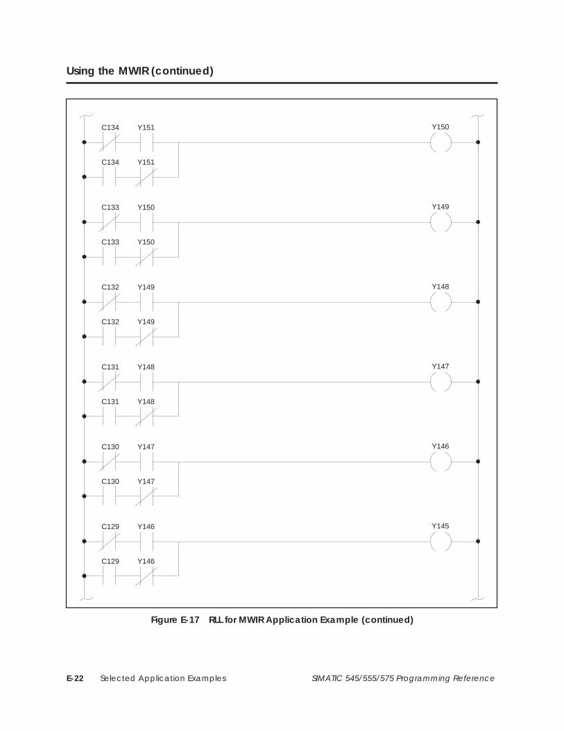
Selected Application ExamplesE-22 SIMATIC 545/555/575 Programming Reference
Using the MWIR (continued)
C134
C134
Y150Y151
Y151
C133
C133
Y149Y150
Y150
C132
C132
Y148Y149
Y149
C131
C131
Y147Y148
Y148
C130
C130
Y146Y147
Y147
C129
C129
Y145Y146
Y146
Figure E-17 RLL for MWIR Application Example (continued)

Selected Application Examples E-23SIMATIC 545/555/575 Programming Reference
C128
C128
Y144Y145
Y145
C127
C127
Y143Y144
Y144
C126
C126
Y142Y143
Y143
C125
C125
Y141Y142
Y142
C124
C124
Y140Y141
Y141
C27 C15
MIRW 3
IR: Y140A: V975N= 15
LSB
Figure E-17 RLL for MWIR Application Example (continued)

Selected Application ExamplesE-24 SIMATIC 545/555/575 Programming Reference
E.9 Using the MWTT
A thermocouple temperature reading is to be logged every five minutes. Thethermocouple input is linearized through a transmitter (shown inFigure E-18) and input to the controller through the first input of an AnalogInput Module in Slot 3 of Base 10 (WX657). The temperature table is to beused for work shift history of trend recording.
TX
Thermocouple
To analog input modulelocated in slot 3; WX657
Figure E-18 MWTT Application Example
The following solution was devised.
• A one shot is turned on every five minutes by a timer.
• The one shot activates the logic to scale the thermocouple input, adds alow end offset temperature, and loads the result into a table with 150locations.
The RLL solution shown in Figure E-19 solves the application.
• Every five minutes, C36 is turned on by a timing circuit (not shown)and C36 turns on one shot 5. One shot 5 activates MULT 38 for thefirst scan in which C36 is on, to multiply the analog input value(WX657) times a scaling constant loaded in memory location V117. Theresult is stored in locations V118 and V119.
• DIV 38 divides the scaled value in V118 and V119 by a constant loadedin V100. The quotient is stored in V120 and the remainder in V121.
• C37 turns on after DIV 38 executes, allowing ADD 38 to add the scaledtemperature input (V120) to an offset temperature value that has beenloaded into V101.
• C38 is energized after ADD 38 executes, allowing MWTT 7 to load thetemperature value (located in V122) into the table at the pointeraddress in V123.
• When MWTT 7 is reset (contact X10 is off for one scan), the pointeraddress in V123 is reset to 700.
• When the pointer address in V123 reaches 849, C39 turns on, and noadditional values are loaded into the table until MWTT 7 is reset.
Application
Explanation

Selected Application Examples E-25SIMATIC 545/555/575 Programming Reference
C36 C37
MULT 38
A: V117B: WX657CC: V118
(V119)
DIV 38
AA: V118(V119)
B: V100CC: V120
(V121)
C37 C38
ADD 38
A: V120B: V101C: V122
C38 C39
MWTT 7
A: V122B: V123S: V700N= 150
X10
:O:5
Figure E-19 RLL for MWTT Application Example

Selected Application ExamplesE-26 SIMATIC 545/555/575 Programming Reference
E.10 Using the MWFT
The following example recovers the data (in locations V700–V849) stored inthe MWTT application example program. The data points are plotted for areport. The plotter is connected to output word WY57. The data shouldchange every second. Therefore, one second on the plot represents fiveminutes of the process.
The RLL solution shown in Figure E-20 solves the application.
• When X1 is turned on, plotting begins. Once every second, TMR1causes C1 to turn on for one scan.
• Each time C1 turns on, MWFT1 transfers a new word from the memorytable to V101, beginning at V700. This continues once per second untilall 150 words have been moved to V101, i.e., until V849 has beentransferred.
• MOVW1 transfers the data in V101 to WY57, that is the plotter outputword.
• Once started, X1 must be cycled off and then on to restart the plottingprocess.
Application
Explanation

Selected Application Examples E-27SIMATIC 545/555/575 Programming Reference
X1 C1
TMR 1
P= 1.0
X1 C1
C1 C2
MWFT 1
A: V100B: V101S: V700N= 150
X1
C2
C1 C3
MOVW 1
A: V101B: WY57
Figure E-20 RLL for MWFT Application Example

Selected Application ExamplesE-28 SIMATIC 545/555/575 Programming Reference
E.11 Using the WXOR
At a critical point in a process, the status of 16 discrete inputs must be in aspecific state to execute an operation. If any of the 16 inputs is not in thecorrect state, an alarm is sounded. There are 16 indicators that displaywhich inputs are in the wrong state.
This application could be solved with contacts and coils without boxfunctions. To save ladder logic and execution speed, use the RLL shown inFigure E-21.
• Before C1 has power flow, V1 is initialized to zero and V2 is loaded tocontain the 16 critical states.
• When the critical process is ready to begin, C1 has power flow causingX1–X16 to be loaded into V3. An Exclusive OR is then executed on V3and V2. V1 contains the result and contains a one in any bit locationwhere V2 and V3 differ. If V2 and V3 are identical, then V1 contains allzeros and the WXOR 1 output C3 does not turn on.
• A difference between V3 and V2 causes C3 to come on. V1 is moved outto indicators Y41–Y56 to show which inputs are incorrect and alarmY33 is latched on.
• Reset switch X17 can be turned on to reset alarm Y33 and to clearindicator panel Y41–Y56.
C1 C2
LDC 1
A: V1N: 0X17
LDC 2
A: V2N: 30006
C1 C3
MIRW 1
IR: X1A: V3N: 16
WXOR 1
A: V3B: V2C: V1
C1 Y33
MWIR 1
A: V1IR: Y41N: 16
C3 X17
Y33
Figure E-21 RLL for WXOR Application Example
Application
Explanation

Selected Application Examples E-29SIMATIC 545/555/575 Programming Reference
Before C1 has power flow, the desired values for X1–X16 are loaded into V2,as shown below.
BIT
V2: = 30,006
1 2 3 4 5 6 7 8 9 10 11 12 13 14 15 16
0 1 1 1 0 1 0 1 0 0 1 1 0 1 1 0
X16 X15 X14 X13 X12 X11 X10 X9 X8 X7 X6 X5 X4 X3 X2 X1
• When C1 is on, the actual values of X1–X16 are loaded into V3:
30,006
1 2 3 4 5 6 7 8 9 10 11 12 13 14 15 16
0 1 1 1 0 1 0 1 0 0 1 1 0 1 1 0
X16 X15 X14 X13 X12 X11 X10 X9 X8 X7 X6 X5 X4 X3 X2 X1
Desired Values In V2 30,0060 1 1 1 0 1 0 1 0 0 1 1 0 1 1 0
00 0 0 0 0 0 0 0 0 0 0 0 0 0 0 0From The WXOR V1 =
X1 = OFF X5 = ON X9 = ON X13 = ONX2 = ON X6 = ON X10 = OFF X14 = ON
X3 = ON X7 = OFF X11 = ON X15 = ONX4 = OFF X8 = OFF X12 = OFF X16 = OFF
Actual Values In V3
• Since the WXOR 1 result is zero, C3 is not turned on, and MWIR 1 inthe next rung is not executed. Alarm Y33 is not sounded.
The inputs from the example above are used, except that inputs #5 and #12are incorrect.
32,038
1 2 3 4 5 6 7 8 9 10 11 12 13 14 15 16
0 1 1 1 1 1 0 1 0 0 1 0 0 1 1 0
X16 X15 X14 X13 X12 X11 X10 X9 X8 X7 X6 X5 X4 X3 X2 X1
30,0060 1 1 1 0 1 0 1 0 0 1 1 0 1 1 0
2,0640 0 0 0 1 0 0 0 0 0 0 1 0 0 0 0
Y56 Y55 Y54 Y53 Y52 Y51 Y50 Y49 Y48 Y47 Y46 Y45 Y44 Y43 Y42 Y41
Desired Values In V2
From The WXOR V1 =
Actual Values In V3
• Since the WXOR result is not all zeros, C3 is turned on and the MWIRis executed. Y45 indicates that X5 is in the wrong state, and Y52indicates that X12 is in the wrong state. Alarm Y33 stays on until resetby X17.
Inputs are Correct
Inputs areIncorrect
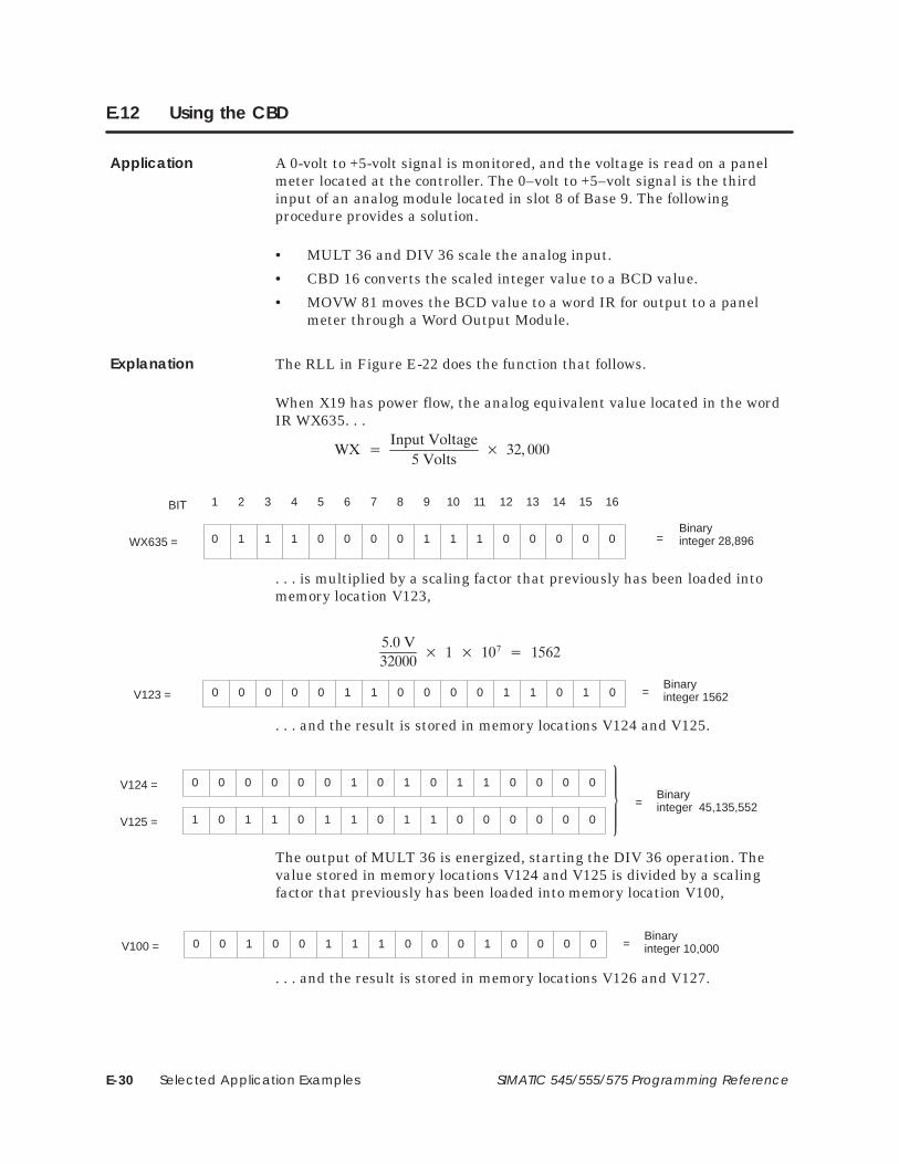
Selected Application ExamplesE-30 SIMATIC 545/555/575 Programming Reference
E.12 Using the CBD
A 0-volt to +5-volt signal is monitored, and the voltage is read on a panelmeter located at the controller. The 0–volt to +5–volt signal is the thirdinput of an analog module located in slot 8 of Base 9. The followingprocedure provides a solution.
• MULT 36 and DIV 36 scale the analog input.
• CBD 16 converts the scaled integer value to a BCD value.
• MOVW 81 moves the BCD value to a word IR for output to a panelmeter through a Word Output Module.
The RLL in Figure E-22 does the function that follows.
When X19 has power flow, the analog equivalent value located in the wordIR WX635. . .
�� ���������������
���������� ��� ���
BIT
WX635 = =
1 2 3 4 5 6 7 8 9 10 11 12 13 14 15 16
0 1 1 1 0 0 0 0 1 1 1 0 0 0 0 0Binaryinteger 28,896
. . . is multiplied by a scaling factor that previously has been loaded intomemory location V123,
V123 = =0 0 0 0 0 1 1 0 0 0 0 1 1 0 1 0Binaryinteger 1562
�����
�������� ���� ��
� �� ���
. . . and the result is stored in memory locations V124 and V125.
V124 =
=
0 0 0 0 0 0 1 0 1 0 1 1 0 0 0 0Binaryinteger 45,135,552
V125 = 1 0 1 1 0 1 1 0 1 1 0 0 0 0 0 0
The output of MULT 36 is energized, starting the DIV 36 operation. Thevalue stored in memory locations V124 and V125 is divided by a scalingfactor that previously has been loaded into memory location V100,
V100 = =0 0 1 0 0 1 1 1 0 0 0 1 0 0 0 0Binaryinteger 10,000
. . . and the result is stored in memory locations V126 and V127.
Application
Explanation

Selected Application Examples E-31SIMATIC 545/555/575 Programming Reference
V126 = =0 0 0 1 0 0 0 1 1 0 1 0 0 0 0 1Binaryinteger 4513
V127 = =0 0 0 1 0 1 0 1 1 0 1 1 0 0 0 0Binaryinteger 5552
The output of DIV 36 energizes C73, starting the CBD 16 operation. Thevalue stored in memory location V126 is converted to its BCD equivalent,and the result is stored in memory locations V128 and V129.
V128 = = 00 0 0 0 0 0 0 0 0 0 0 0 0 0 0 0
V129 = = BCD 45130 1 0 0 0 1 0 1 0 0 0 1 0 0 1 1
4 5 1 3
The output of CBD 16 energizes, starting the MOVW 81 operation. Thevalue stored in memory location V129 is moved to the output IR WY65. IRWY65 outputs the BCD number to a Word Output Module located in Slot 1of Base 1. WY65 is the first output of this module. A reading of 4.513 volts isdisplayed on a digital panel meter where the decimal point is fixedinternally to the panel meter.
From analog input or WX, V input = (Binary integer x 5 volts) ÷ 32,000
X19 C73MULT 36
A: WX635B: V123CC: V124
(V125)
C73 C74CBD 16
A: V126BB: V128
(V129)
DIV 36
AA: V124(V125)
B: V100CC: V126
(V127)
MOVW 81
A: V129B: WY65N= 1
Figure E-22 RLL for CBD Application Example

Selected Application ExamplesE-32 SIMATIC 545/555/575 Programming Reference
E.13 Using the CDB
BCD thumbwheels are input 2 of a Word Input Module located in Slot 3 ofBase 6 (WX402). The thumbwheel input is to be converted to a binaryinteger equivalent for use in mathematics instructions.
The following solution was devised.
• CDB 1 converts the word input from BCD to an integer.
• DIV 3 is a mathematics instruction in which the divisor is modified bya thumbwheel switch.
Figure E-23 shows the RLL for this operation.
• When contact C67 has power flow, CDB 1 converts the BCD valuelocated in IR WX402 to an integer value, that is put in memory locationV238.
10WX402 64040
1
0 1 0
9
0 1 0 0
0
0 0 0 1
4
0 0
0 19040 0 0 0 1 1 1 0 1 1 1 0 0 0 0 10
10
V238
1 9 0 4
• DIV 3 divides V635 and V636 by V238, and puts the quotient in V79.
• Coil C1 is energized when the instructions execute.
C67 C1
CDB 1
A: WX402B: V238N= 4
DIV 3
AA: V635(V636)
B: V238CC: V79
(V80)
Figure E-23 RLL for CDB Application Example
Application
Explanation

Selected Application Examples E-33SIMATIC 545/555/575 Programming Reference
E.14 Using the One Shot
Each time a momentary pushbutton is pressed, an ADD executes once. Thepushbutton address is X1.
The following solution was devised.
• A one shot preceding an ADD instruction solves this example.
Figure E-24 shows the RLL for this operation.
• When X1 is pressed, the output of one shot 20 is energized for onecontroller scan, and ADD 41 executes only during this controller scan.
• X1 must be turned off for at least one controller scan, and then turnedon again, for the ADD 41 to execute again.
Values prior to network execution:WX100= 7010
WX101= 5110 V74= 010
Values after network execution:WX100= 7010WX101= 5110V74= 121
X1 C1
A: WX100B: WX101C: V74
ADD 41:O:20
Figure E-24 RLL for One Shot Application Example
If all the One Shot instruction numbers have been used, you can build onefrom RLL, as shown in Figure E-25.
X1 Y9C10
X1 C10
Figure E-25 Constructing a One Shot From RLL
Application
Explanation

Selected Application ExamplesE-34 SIMATIC 545/555/575 Programming Reference
E.15 Using the DCAT
A remotely located pipeline valve is opened and closed by control logic.Because of the diameter of the pipeline, the valve requires 30 seconds toopen or close. Feedback for the valve status informs maintenance personnelwhether the valve is open, closed, traveling, failed to open, failed to close, orthe sensor has failed. See Figure E-26.
Electro-solenoid
Normally openopen feedback switch
normally open closed feedback switch
X17
X18
Failed to openalarm
Failed to closealarm
Controller logic controls Y7
Y7=1=open valve
Y7=0=close valve
Y1
Y2
Y3
Y4
Sensor alarm
Traveling indicator
Figure E-26 DCAT Application Example
The following solution was devised.
• Control logic opens or closes the valve by sending power flow toelectro-solenoid Y7.
• Limit Switch X17 is the normally open feedback switch that closes toindicate that the valve is open.
• Limit Switch X18 is the normally open feedback switch that closes toindicate that the valve is closed.
• While the valve transitions, the Y4 indicator (traveling) is on.
• If the valves fails to open, alarm Y1 turns on.
• If the valves fails to close, alarm Y2 turns on.
• If both feedback sensors are closed (for example, a sensor sticks), sensorfailure alarm Y3 is turned on.
Application

Selected Application Examples E-35SIMATIC 545/555/575 Programming Reference
The RLL solution is shown in Figure E-27. Valve control is accomplished bythe events described below. Other program steps control the status of valveY7 by turning Control Relay C40 off or on. Y7 follows the status of C40,unaffected by the DCAT instruction.
Under normal conditions, the following events occur.
• If C40 goes to 1 (on), X17, X18, C5, and C6 are 0 (off) as long as it takesthe valve to open.
• Subsequent program steps check the status of X17, X18, C5, and C6. Ifthey are all off, the valve status is reported through indicator Y4 astraveling.
• Open feedback sensor X17 then closes and disables Open Alarm C5.
• If C40 goes to 0 (off) and commands the valve to close, closed feedbacksensor X18 closes and disables the Close Alarm C6.
Y7C40
C5 C6
C5 C6
C5 C6
X17 X18 C5 C6
Y1
Y2
Y3
Y4
failed to open
failed to close
failed sensor
traveling
P= 30OF: X17CF: X18OA: C5CA: C6
DCAT 4
Figure E-27 RLL for DCAT Application Example
Explanation
Normal Operation

Selected Application ExamplesE-36 SIMATIC 545/555/575 Programming Reference
Using the DCAT (continued)
If the valve fails to open, the following events occur.
• If C40 goes to 1 (on), commanding the valve to open, and open feedbackdoes not turn on, the timer times out and energizes Open Alarm C5.
• Subsequent RLL steps check the status of C5 and C6. If C5=1 andC6=0; the failed to open indicator Y1 turns on.
If the valve fails to close, the following events occur.
• If C40 goes to 0 (off), commanding the valve to close, and closedfeedback does not turn on, the timer times out and energizes ClosedAlarm C6.
• Subsequent RLL steps check the status of C5 and C6. If C5=0 andC6=1, the failed to close indicator Y2 turns on.
If the sensor fails, the following events occur.
• At any time that X17 and X18 are both on, the DCAT turns on C5 andC6. Y4 reports a failure of the valve sensor system.
Valve Fails to Open
Valve Fails to Close
Sensor Fails

Selected Application Examples E-37SIMATIC 545/555/575 Programming Reference
E.16 Using Status Words
A procedure is required that logs off a failed I/O module and logs on abackup-module in the same base.
NOTE: Only self-diagnosing modules can indicate their own failure.
Y24 = Module Failure Alarm. Example module assignments:
• Module 1 in slot 1, Base 0 = WX1 to WX8 — STW11, Bit 16
• Module 2 in slot 2, Base 1 = WX9 to WX16 — STW12, Bit 15
• Module 3 in slot 3, Base 0 = Y17 to Y24
The RLL solution is shown in Figure E-28. The status of Input Module #1 ischecked with a bit-of-word contact. If the contact turns on (bit 16 inSTW11 = 1), the alarm Y24 turns on. The program then uses Y24 todetermine which module should source V200 through V207.
For this method to function in an application, both input modules must behardwired to the same field devices (i.e. WX1 through WX8 should beconnected to the same devices, such as WX9 through WX16, respectively).
STW11.16 Y24
Y24 C22
A: WX1B: V200N= 8
MOVW 1
Y24 C23
MOVW 2A: WX9B: V200N= 8
Alarm
Figure E-28 RLL for Status Word Application Example
Application
Explanation

Special Function Program Error Codes F-1SIMATIC 545/555/575 Programming Reference
Appendix F
Special Function Program Error Codes
Table F-1 Special Function Error Codes
CodeMeanin
Hex DecimalMeaning
02 02 Address out of range.
03 03 Requested data not found.
09 09 Incorrect amount of data sent with request.
11 17 Invalid data.
40 64 Operating system error detected.
42 66 Control block number out of range.
43 67 Control block does not exist or has not been compiled.
46 70 Offset out of range.
47 71 Arithmetic error detected while writing loop or analog alarm parameters.
48 72 Invalid SF program type.
49 73 Instruction number or ramp/soak step number out of range.
4A 74 Attempt to access an integer-only variable as a real.
4B 75 Attempt to access a real-only variable as an integer.
4E 78 Attempt to write a read-only variable (for example: X, WX, or STW).
4F 79 Invalid variable data type for this operation.
52 82 Invalid return value.
53 83 Attempt to execute a Cyclic Statement in a non-cyclic SF program.
54 84 Control block is disabled.
56 86 Attempt to perform an FTSR-OUT Statement on an empty FIFO.
57 87 Attempt to perform an FTSR-IN Statement on a full FIFO.
58 88 Stack overflow while evaluating a MATH, IF, or IMATH expression.
59 89 Maximum SFSUB nesting level exceeded. Subroutines may only be nested to adepth of 4.
5A 90 Arithmetic Overflow.
5B 91 Invalid operator in an IF, MATH, or IMATH expression.
5D 93 Attempt to divide by zero (IMATH statement).
5E 94 FIFO is incompatible with FTSR-IN/FTSR-OUT statement.
5F 95 FIFO is invalid.
60 96 Invalid Data Type code. This error is generally caused by an ill-formed MATH,IMATH, or IF expression.

Status Words G-1SIMATIC 545/555/575 Programming Reference
Appendix G
Status Words
STW01: Non-fatal Errors G-2. . . . . . . . . . . . . . . . . . . . . . . . . . . . . . . . . . . . . . . . . . . . . . . . . . . . . . . . . . . . . . . . . STW02: Base Controller Status G-3. . . . . . . . . . . . . . . . . . . . . . . . . . . . . . . . . . . . . . . . . . . . . . . . . . . . . . . . . . . STW03 – STW09: PROFIBUS-DP Slave Status G-4. . . . . . . . . . . . . . . . . . . . . . . . . . . . . . . . . . . . . . . . . . . . . . . . STW10: Dynamic Scan Time G-4. . . . . . . . . . . . . . . . . . . . . . . . . . . . . . . . . . . . . . . . . . . . . . . . . . . . . . . . . . . . . STW11 – STW138: I/O Module Status G-5. . . . . . . . . . . . . . . . . . . . . . . . . . . . . . . . . . . . . . . . . . . . . . . . . . . . . . STW139: Discrete Force Count G-8. . . . . . . . . . . . . . . . . . . . . . . . . . . . . . . . . . . . . . . . . . . . . . . . . . . . . . . . . . . STW140: Word Force Count G-8. . . . . . . . . . . . . . . . . . . . . . . . . . . . . . . . . . . . . . . . . . . . . . . . . . . . . . . . . . . . . STW141 – STW144: Date, Time, and Day of Week G-8. . . . . . . . . . . . . . . . . . . . . . . . . . . . . . . . . . . . . . . . . STW145 – STW146: Receive and Timeout Errors G-11. . . . . . . . . . . . . . . . . . . . . . . . . . . . . . . . . . . . . . . . . . . STW147: PROFIBUS-DP Slave Errors G-11. . . . . . . . . . . . . . . . . . . . . . . . . . . . . . . . . . . . . . . . . . . . . . . . . . . . . . . STW148: PROFIBUS-DP Bus Communication Errors G-11. . . . . . . . . . . . . . . . . . . . . . . . . . . . . . . . . . . . . . . . . STW149 - STW160: Reserved G-11. . . . . . . . . . . . . . . . . . . . . . . . . . . . . . . . . . . . . . . . . . . . . . . . . . . . . . . . . . . . . STW161: Special Function Processor Fatal Errors G-12. . . . . . . . . . . . . . . . . . . . . . . . . . . . . . . . . . . . . . . . . . . STW162: Special Function Processor Non-fatal Errors G-13. . . . . . . . . . . . . . . . . . . . . . . . . . . . . . . . . . . . . . STW163: RLL Subroutine Stack Overflow G-14. . . . . . . . . . . . . . . . . . . . . . . . . . . . . . . . . . . . . . . . . . . . . . . . . . STW164 – STW165: L-Memory Checksum C0 G-14. . . . . . . . . . . . . . . . . . . . . . . . . . . . . . . . . . . . . . . . . . . . . . STW166 – STW167: L-Memory Checksum C1 G-14. . . . . . . . . . . . . . . . . . . . . . . . . . . . . . . . . . . . . . . . . . . . . . STW168: Dual RBC Status G-15. . . . . . . . . . . . . . . . . . . . . . . . . . . . . . . . . . . . . . . . . . . . . . . . . . . . . . . . . . . . . . . . STW169 – STW175: Reserved G-16. . . . . . . . . . . . . . . . . . . . . . . . . . . . . . . . . . . . . . . . . . . . . . . . . . . . . . . . . . . . . STW176: Dual Power Supply Status G-16. . . . . . . . . . . . . . . . . . . . . . . . . . . . . . . . . . . . . . . . . . . . . . . . . . . . . . . STW177 – STW183: Reserved G-17. . . . . . . . . . . . . . . . . . . . . . . . . . . . . . . . . . . . . . . . . . . . . . . . . . . . . . . . . . . . . STW184: Module Mismatch Indicator G-17. . . . . . . . . . . . . . . . . . . . . . . . . . . . . . . . . . . . . . . . . . . . . . . . . . . . STW185 – STW191: Reserved G-17. . . . . . . . . . . . . . . . . . . . . . . . . . . . . . . . . . . . . . . . . . . . . . . . . . . . . . . . . . . . . STW192: Discrete Scan Execution Time G-17. . . . . . . . . . . . . . . . . . . . . . . . . . . . . . . . . . . . . . . . . . . . . . . . . . . STW193 – STW199: Reserved G-17. . . . . . . . . . . . . . . . . . . . . . . . . . . . . . . . . . . . . . . . . . . . . . . . . . . . . . . . . . . . . STW200: User Error Cause G-18. . . . . . . . . . . . . . . . . . . . . . . . . . . . . . . . . . . . . . . . . . . . . . . . . . . . . . . . . . . . . . . STW201: First Scan Flags G-19. . . . . . . . . . . . . . . . . . . . . . . . . . . . . . . . . . . . . . . . . . . . . . . . . . . . . . . . . . . . . . . . . STW202: Application Mode Flags (A – P) G-20. . . . . . . . . . . . . . . . . . . . . . . . . . . . . . . . . . . . . . . . . . . . . . . . . STW203: Application Mode Flags (Q – Z) G-21. . . . . . . . . . . . . . . . . . . . . . . . . . . . . . . . . . . . . . . . . . . . . . . . . STW204: Application Installed Flags (A – P) G-22. . . . . . . . . . . . . . . . . . . . . . . . . . . . . . . . . . . . . . . . . . . . . . . STW205: Application Installed Flags (Q – Z) G-23. . . . . . . . . . . . . . . . . . . . . . . . . . . . . . . . . . . . . . . . . . . . . . . STW206 – STW207: U-Memory Checksum C0 G-24. . . . . . . . . . . . . . . . . . . . . . . . . . . . . . . . . . . . . . . . . . . . . . STW208 – STW209: U-Memory Checksum C1 G-24. . . . . . . . . . . . . . . . . . . . . . . . . . . . . . . . . . . . . . . . . . . . . . STW210: Base Poll Enable Flags G-25. . . . . . . . . . . . . . . . . . . . . . . . . . . . . . . . . . . . . . . . . . . . . . . . . . . . . . . . . . STW211 – STW217: PROFIBUS-DP Slave Enable Flags G-26. . . . . . . . . . . . . . . . . . . . . . . . . . . . . . . . . . . . . . . STW218: My Application ID G-26. . . . . . . . . . . . . . . . . . . . . . . . . . . . . . . . . . . . . . . . . . . . . . . . . . . . . . . . . . . . . . STW219: RLL Task Overrun G-26. . . . . . . . . . . . . . . . . . . . . . . . . . . . . . . . . . . . . . . . . . . . . . . . . . . . . . . . . . . . . . . STW220: Interrupting Slots in Local Base G-27. . . . . . . . . . . . . . . . . . . . . . . . . . . . . . . . . . . . . . . . . . . . . . . . . . STW221: Module Interrupt Request Count G-27. . . . . . . . . . . . . . . . . . . . . . . . . . . . . . . . . . . . . . . . . . . . . . . . STW222: Spurious Interrupt Count G-27. . . . . . . . . . . . . . . . . . . . . . . . . . . . . . . . . . . . . . . . . . . . . . . . . . . . . . . . STW223 – STW225: Binary Time-of-Day G-28. . . . . . . . . . . . . . . . . . . . . . . . . . . . . . . . . . . . . . . . . . . . . . . . . . . . STW226: Time-of-Day Status G-28. . . . . . . . . . . . . . . . . . . . . . . . . . . . . . . . . . . . . . . . . . . . . . . . . . . . . . . . . . . . . STW227 – STW228: Bus Error Access Address G-30. . . . . . . . . . . . . . . . . . . . . . . . . . . . . . . . . . . . . . . . . . . . . . STW229 – STW230: Bus Error Program Offset G-30. . . . . . . . . . . . . . . . . . . . . . . . . . . . . . . . . . . . . . . . . . . . . . . STW231 PROFIBUS-DP I/O System Status G-31. . . . . . . . . . . . . . . . . . . . . . . . . . . . . . . . . . . . . . . . . . . . . . . . . . STW232 – STW238: PROFIBUS-DP Slave Diagnostic G-31. . . . . . . . . . . . . . . . . . . . . . . . . . . . . . . . . . . . . . . . . STW239 – STW240: CS-Memory Checksum C0 G-32. . . . . . . . . . . . . . . . . . . . . . . . . . . . . . . . . . . . . . . . . . . . STW241 – STW242: CS-Memory Checksum C1 G-32. . . . . . . . . . . . . . . . . . . . . . . . . . . . . . . . . . . . . . . . . . . .

Status WordsG-2 SIMATIC 545/555/575 Programming Reference
Each status word description explains the function or purpose of each bitwithin the word. If a bit is not used, it is not described; all unused bits areset to zero. If several bits perform a single function, they are described by asingle definition. If a status word is reserved, it is noted accordingly.
MSB LSB
5
6
7
8
10
11
12
13
14
15
16151413121110987654321
1 = Subroutine stack overflow
1 = User program error; see STW200
1 = Time of day clock failure
1 = Previous RLL instruction failed
1 = Communication port failure
1 = I/O module failure or I/O configuration mismatch
1 = Battery low
1 = Scan overrun
1 = Special function module communication error
1 = A Password has been entered and is disabled
NOTE: For the controllers that support the TASK instruction, STW1 cannot be accessedby a multi-word move instruction, e.g., MOVE, MOVW. STW1 is a local variable that isonly valid within a given RLL task. Do not do multiple-word move operations that beginwith STW1.
1 = Password has been entered
4
Applicable Controller ALL
STW01:Non-fatal Errors

Status Words G-3SIMATIC 545/555/575 Programming Reference
16151413121110987654321
Base 15: 0 = Status good; 1 = Base not present or has problem
Base 13: 0 = Status good; 1 = Base not present or has problem
Base 14: 0 = Status good; 1 = Base not present or has problem
Base 11: 0 = Status good; 1 = Base not present or has problem
Base 12: 0 = Status good; 1 = Base not present or has problem
Base 9: 0 = Status good; 1 = Base not present or has problem
Base 10: 0 = Status good; 1 = Base not present or has problem
Base 8: 0 = Status good; 1 = Base not present or has problem
MSB LSB
Base 7: 0 = Status good; 1 = Base not present or has problem
Base 5: 0 = Status good; 1 = Base not present or has problem
Base 6: 0 = Status good; 1 = Base not present or has problem
Base 3: 0 = Status good; 1 = Base not present or has problem
Base 4: 0 = Status good; 1 = Base not present or has problem
Base 1: 0 = Status good; 1 = Base not present or has problem
Base 2: 0 = Status good; 1 = Base not present or has problem
Base 0: 0 = Status good; 1 = Base not present or has problem
1
2
3
4
5
6
7
8
9
10
11
12
13
14
15
16
Applicable Controller ALL
STW02: BaseController Status

Status WordsG-4 SIMATIC 545/555/575 Programming Reference
16151413121110987654321Bit
STW03 16 15 14 13 12 11 10 9 8 7 6 5 4 3 2 1
STW04 32 31 30 29 28 27 26 25 24 23 22 21 20 19 18 17
STW05 48 47 46 45 44 43 42 41 40 39 38 37 36 35 34 33
STW06 64 63 62 61 60 59 58 57 56 55 54 53 52 51 50 49
STW07 80 79 78 77 76 75 74 73 72 71 70 69 68 67 66 65
STW08 96 95 94 93 92 91 90 89 88 87 86 85 84 83 82 81
STW09 112 111 110 109 108 107 106 105 104 103 102 101 100 99 98 97
MSB LSB
STW03 through STW09 give the status for PROFIBUS-DP slaves. Theslave’s bit, as indicated in the cells above, is a 1 if the slave is not present oris failed.
16151413121110987654321
Binary value of previous scan time
MSB LSB
Applicable Controller ALL
Figure G-1 illustrates an example of STW10 containing a scan time of145 ms.
MSB LSB
1000100100000000STW10
Figure G-1 Example of Status Word Reporting Scan Time
STW03 – STW09:PROFIBUS-DP SlaveStatus
STW10:Dynamic ScanTime

Status Words G-5SIMATIC 545/555/575 Programming Reference
Status words STW11 through STW138 indicate the status of the individualI/O modules installed in the local base, an RBC in a remote base, or aPPX:505–6870 RBC on the PROFIBUS-DP I/O channel. Statusword 11 applies to the local base, status words 12 – 26 apply to the 505remote I/O channel, and status words 27 – 138 apply to the PROFIBUS-DPI/O channel. The illustration on page G-6 shows the content of these statuswords. Table G-1 lists the status words that correspond to the status of eachbase/slave.
Table G-1 Status Words 11 Through 138
Statusword
505 ModulesLocal/Remote
Statusword
PROFIBUS-DPModule
Statusword
PROFIBUS-DPModule
Statusword
PROFIBUS-DPModule
11 Local Base 27 Slave 1 43 Slave 17 59 Slave 33
12 Remote I/O Base 1 28 Slave 2 44 Slave 18 60 Slave 34
13 Remote I/O Base 2 29 Slave 3 45 Slave 19 61 Slave 35
14 Remote I/O Base 3 30 Slave 4 46 Slave 20 62 Slave 36
15 Remote I/O Base 4 31 Slave 5 47 Slave 21 63 Slave 37
16 Remote I/O Base 5 32 Slave 6 48 Slave 22 64 Slave 38
17 Remote I/O Base 6 33 Slave 7 49 Slave 23 65 Slave 39
18 Remote I/O Base 7 34 Slave 8 50 Slave 24 66 Slave 40
19 Remote I/O Base 8 35 Slave 9 51 Slave 25 67 Slave 41
20 Remote I/O Base 9 36 Slave 10 52 Slave 26 68 Slave 42
21 Remote I/O Base 10 37 Slave 11 53 Slave 27 69 Slave 43
22 Remote I/O Base 11 38 Slave 12 54 Slave 28 70 Slave 44
23 Remote I/O Base 12 39 Slave 13 55 Slave 29 71 Slave 45
24 Remote I/O Base 13 40 Slave 14 56 Slave 30 72 Slave 46
25 Remote I/O Base 14 41 Slave 15 57 Slave 31 73 Slave 47
26 Remote I/O Base 15 42 Slave 16 58 Slave 32 74 Slave 48
Statusword
PROFIBUS-DPModule
Statusword
PROFIBUS-DPModule
Statusword
PROFIBUS-DPModule
Statusword
PROFIBUS-DPModule
75 Slave 49 91 Slave 65 107 Slave 81 123 Slave 97
76 Slave 50 92 Slave 66 108 Slave 82 124 Slave 98
77 Slave 51 93 Slave 67 109 Slave 83 125 Slave 99
78 Slave 52 94 Slave 68 110 Slave 84 126 Slave 100
79 Slave 53 95 Slave 69 111 Slave 85 127 Slave 101
80 Slave 54 96 Slave 70 112 Slave 86 128 Slave 102
81 Slave 55 97 Slave 71 113 Slave 87 129 Slave 103
82 Slave 56 98 Slave 72 114 Slave 88 130 Slave 104
83 Slave 57 99 Slave 73 115 Slave 89 131 Slave 105
84 Slave 58 100 Slave 74 116 Slave 90 132 Slave 106
85 Slave 59 101 Slave 75 117 Slave 91 133 Slave 107
86 Slave 60 102 Slave 76 118 Slave 92 134 Slave 108
87 Slave 61 103 Slave 77 119 Slave 93 135 Slave 109
88 Slave 62 104 Slave 78 120 Slave 94 136 Slave 110
89 Slave 63 105 Slave 79 121 Slave 95 137 Slave 111
90 Slave 64 106 Slave 80 122 Slave 96 138 Slave 112
STW11 – STW138:I/O Module Status

Status WordsG-6 SIMATIC 545/555/575 Programming Reference
16151413121110987654321
Module 16: 0 = Status good; 1 = Module not present or has problem
Module 14: 0 = Status good; 1 = Module not present or has problem
Module 15: 0 = Status good; 1 = Module not present or has problem
Module 12: 0 = Status good; 1 = Module not present or has problem
Module 13: 0 = Status good; 1 = Module not present or has problem
Module 10: 0 = Status good; 1 = Module not present or has problem
Module 1 1: 0 = Status good; 1 = Module not present or has problem
Module 9: 0 = Status good; 1 = Module not present or has problem
MSB LSB
Module 8: 0 = Status good; 1 = Module not present or has problem
Module 6: 0 = Status good; 1 = Module not present or has problem
Module 7: 0 = Status good; 1 = Module not present or has problem
Module 4: 0 = Status good; 1 = Module not present or has problem
Module 5: 0 = Status good; 1 = Module not present or has problem
Module 2: 0 = Status good; 1 = Module not present or has problem
Module 3: 0 = Status good; 1 = Module not present or has problem
Module 1: 0 = Status good; 1 = Module not present or has problem
1
2
3
4
5
6
7
8
9
10
11
12
13
14
15
16
Applicable Controller ALL

Status Words G-7SIMATIC 545/555/575 Programming Reference
The controller reports an I/O mismatch (an installed module that does notagree with the I/O configuration) as a failed I/O module. Although themodule has not actually failed, you must enter correct I/O configurationdata or install the proper module to correct the failure report.
In Figure G-2, the 1 in bit 10 indicates that slot seven in Base 4 contains adefective or incorrectly configured module (I/O mismatch). All other slotseither contain correctly configured, working modules or are correctlyconfigured as empty.
MSB LSB
0000001000000000STW15
Module 7: 1 = Module not present or has problem
10
Figure G-2 Example of Status Word Reporting a Module Failure
NOTE: When a 505 remote I/O base loses communication with thecontroller, the appropriate bit in STW02 shows a 1. The bits in the statusword (STW11–STW26) corresponding to the modules in that base showzeroes, even if modules on that base have failed or been incorrectlyconfigured. That is, the modules of a failed base are not individuallyindicated as failed.
When a PPX:505–6870 RBC loses communication with the controller, theappropriate bit in STW02 shows a 1. The bits in the status word(STW27–STW138) corresponding to the slave module maintain their mostrecent value.
When you disable a base from the TISOFT I/O Configuration Screen, all bitsin the status word (STW11–STW138) that corresponds to that base are setto zero.
STW11 – STW138:(continued)

Status WordsG-8 SIMATIC 545/555/575 Programming Reference
Status word STW139 provides a count of discrete points (X/Y or C) that arecurrently forced.
Status word STW140 provides a count of word points (WX/WY) that arecurrently forced.
16151413121110987654321STW141
Year – tens digit
Month – tens digit
Year – units digit
Month – units digit
MSB LSB
1 2 3 4
5 6 7 8
9 10 11 12
13 14 15 16
16151413121110987654321STW142
MSB LSB
1 2 3 4
5 6 7 8
9 10 11 12
13 14 15 16
Day – tens digit
Hour – tens digit
Day – units digit
Hour – units digit
See also the description of Time of Day Status for STW226 on G–33.
NOTE: The time of day is initialized to 1-Jan-1984 at 12:00 AM. (See alsoSTW223-STW226.)
STW139: DiscreteForce Count
STW140: WordForce Count
STW141 – STW144:Date, Time, andDay of Week

Status Words G-9SIMATIC 545/555/575 Programming Reference
16151413121110987654321STW143
Minute – tens digit
Second – tens digit
Minute – units digit
Second – units digit
MSB LSB
1 2 3 4
5 6 7 8
9 10 11 12
13 14 15 16
STW144 16151413121110987654321
MSB LSB
1 2 3 4
5 6 7 8
9 10 11 12
13 14 15 16
Second – tenths digit *
Not used, always 0
Second – hundredths digit *
Day of the week
* The resolution of these units of time is controller specific. A controller fills a field withzeros for time units that it does not support.
Applicable Controller ALL

Status WordsG-10 SIMATIC 545/555/575 Programming Reference
Figure G-3 illustrates clock information on the date: Monday, 5 October,1992 at 6:39:51.76 P.M. Note that the 24-hour (military) format is used andSunday is assumed to be day 1.
MSB LSB
0000100001001001STW141
MSB LSB
0001100010100000STW142
MSB LSB
1000101010011100STW143
MSB LSB
0100000001101110STW144
Figure G-3 Example of Status Words Reporting Time

Status Words G-11SIMATIC 545/555/575 Programming Reference
Status words STW145 and STW146 contain communication error counts forRemote I/O channel one. The channel records the number of receive errorsand the number of timeout errors which have occurred since the most recentrestart as shown in Table G-2. The counts are in binary.
Table G-2 Receive Errors and Timeout Errors for STW145 and STW146
Receive Errors Timeout Errors
Channel Status Word Channel Status Word
1 STW145 1 STW146
NOTE: A typical system should have no more than one detected andcorrected error over the I/O link per 20,000 scans. If this error rate isexceeded, it may indicate a possible wiring or noise problem. Threeconsecutive errors to an RBC causes the base to be logged off and thecorresponding bit in STW2 to be set.
Status word STW147 records the number of times, since the most recentrestart, that PROFIBUS-DP slaves have failed to respond to a request fromthe Series 505 CPU.
Status word STW148 indicates the number of times, since the most recentrestart, that the PROFIBUS-DP I/O channel has experienced a loss oftoken, possibly due to a problem with the cable. Such errors generally causetotal failure for the PROFIBUS-DP I/O link.
Reserved.
STW145 – STW146:Receive andTimeout Errors
STW147:PROFIBUS-DP SlaveErrors
STW148:PROFIBUS-DP BusCommunicationErrors
STW149 - STW160:Reserved

Status WordsG-12 SIMATIC 545/555/575 Programming Reference
1 = ROM error
1 = Operating system error
1 = RAM error
1 = Diagnostic failure
1 = Invalid control block encountered
1 = S-Memory is inconsistent
1 = Special function program received from RLL is invalid
MSB LSB
1
2
3
4
5
6
7
16151413121110987654321
Applicable Controller ALL
STW161:Special FunctionProcessor FatalErrors

Status Words G-13SIMATIC 545/555/575 Programming Reference
1 =Printer Port 1 communications error*
1 = Loop overrun error
1 = Cyclic special function programs overrun error
1 = Analog alarm overrun error
1 = Priority special function program queue is full
1 = Normal special function program queue is full
1 = Cyclic special function program queue is full
MSB LSB
1 = Loop calculation error
1 = Control block disabled
1 = Analog alarm calculation error
1 = Attempt to invoke restricted SF program or SF subroutine
1 = Attempt to execute undefined SF program or SF subroutine
1
3
4
5
6
7
8
9
10
11
12
13
* A Printer Port 1 communications error is logged if the 545, 555, or 575CPU card has a character queued for printing to Printer Port 1 for morethan 30 seconds.
16151413121110987654321
Applicable Controller ALL
STW162:Special FunctionProcessorNon-fatal Errors

Status WordsG-14 SIMATIC 545/555/575 Programming Reference
Number of the subroutine that caused the stack overflow*
MSB LSB
* Does not apply to XSUB routines.
16151413121110987654321
Applicable Controller ALL
L-Memory checksum C0 MSW
MSB LSB
16151413121110987654321
STW164
L-Memory checksum C0 LSWSTW165
Applicable Controller ALL
L-Memory checksum C1 MSW
MSB LSB
16151413121110987654321
STW166
L-Memory checksum C1 LSWSTW167
Applicable Controller ALL
STW163:RLL SubroutineStack Overflow
STW164 – STW165:L-MemoryChecksum C0
STW166 – STW167:L-MemoryChecksum C1

Status Words G-15SIMATIC 545/555/575 Programming Reference
Base 15: 0 = Dual RBCs present and good; 1 = Error or single RBC
Base 13: 0 = Dual RBCs present and good; 1 = Error or single RBC
Base 14: 0 = Dual RBCs present and good; 1 = Error or single RBC
Base 11: 0 = Dual RBCs present and good; 1 = Error or single RBC
Base 12: 0 = Dual RBCs present and good; 1 = Error or single RBC
Base 9: 0 = Dual RBCs present and good; 1 = Error or single RBC
Base 10: 0 = Dual RBCs present and good; 1 = Error or single RBC
Base 8: 0 = Dual RBCs present and good; 1 = Error or single RBC
MSB LSB
Base 7: 0 = Dual RBCs present and good; 1 = Error or single RBC
Base 5: 0 = Dual RBCs present and good; 1 = Error or single RBC
Base 6: 0 = Dual RBCs present and good; 1 = Error or single RBC
Base 3: 0 = Dual RBCs present and good; 1 = Error or single RBC
Base 4: 0 = Dual RBCs present and good; 1 = Error or single RBC
Base 1: 0 = Dual RBCs present and good; 1 = Error or single RBC
Base 2: 0 = Dual RBCs present and good; 1 = Error or single RBC
Base 0: 0 = Dual RBCs present and good; 1 = Error or single RBC
1
2
3
4
5
6
7
8
9
10
11
12
13
14
15
16
16151413121110987654321
Applicable Controller ALL
STW168: Dual RBC Status

Status WordsG-16 SIMATIC 545/555/575 Programming Reference
Reserved.
Base 15: 0 = Dual P/S present and good; 1 = Error or single P/S
Base 13: 0 = Dual P/S present and good; 1 = Error or single P/S
Base 14: 0 = Dual P/S present and good; 1 = Error or single P/S
Base 11: 0 = Dual P/S present and good; 1 = Error or single P/S
Base 12: 0 = Dual P/S present and good; 1 = Error or single P/S
Base 9: 0 = Dual P/S present and good; 1 = Error or single P/S
Base 10: 0 = Dual P/S present and good; 1 = Error or single P/S
Base 8: 0 = Dual P/S present and good; 1 = Error or single P/S
MSB LSB
Base 7: 0 = Dual P/S present and good; 1 = Error or single P/S
Base 5: 0 = Dual P/S present and good; 1 = Error or single P/S
Base 6: 0 = Dual P/S present and good; 1 = Error or single P/S
Base 3: 0 = Dual P/S present and good; 1 = Error or single P/S
Base 4: 0 = Dual P/S present and good; 1 = Error or single P/S
Base 1: 0 = Dual P/S present and good; 1 = Error or single P/S
Base 2: 0 = Dual P/S present and good; 1 = Error or single P/S
Base 0: 0 = Dual P/S present and good; 1 = Error or single P/S
1
2
3
4
5
6
7
8
9
10
11
12
13
14
15
16
16151413121110987654321
Applicable Controller ALL
STW169 – STW175:Reserved
STW176:Dual Power SupplyStatus

Status Words G-17SIMATIC 545/555/575 Programming Reference
Reserved.
Base having module failure
1 = Module failure
Number of the base with the module mismatch error
1 = Module mismatch error
MSB LSB
1
5 6 7 8
0000 = base 01111 = base 15
16151413121110987654321
9
13 14 15 16
Note: Bits 9–16 as shown apply to systems that supportremote I/O only. For systems that support both remoteI/O and PROFIBUS-DP I/O, bits 9–16 are always 0.
Applicable Controller ALL
Reserved.
Discrete scan execution time in milliseconds
MSB LSB
16151413121110987654321
Applicable Controller ALL
Reserved.
STW177 – STW183:Reserved
STW184:Module MismatchIndicator
STW185 – STW191:Reserved
STW192:Discrete ScanExecution Time
STW193 – STW199:Reserved

Status WordsG-18 SIMATIC 545/555/575 Programming Reference
Error reason code associated with bit 6 of STW01
MSB LSB
Currently defined integer values:0 No error1 Reference to an application that is not installed (575 only)2 Attempted to unlock a flag that is not held by an application (575 only)3 Mismatched LOCK/UNLOCK instructions (575 only)4 Exceeded subroutine nesting level5 Table overflow6 Attempted to call a non-existent subroutine7 VMEbus access failed due to a bus error (575 only)8 SF program does not exist or has not been compiled (PowerMath CPUs only)9 SF program is not enabled (PowerMath CPUs only)10 SF program marked for in-line is cyclic or restricted (PowerMath CPUs only)11 In-line SF program or subroutine: edit operation is in progress. (PowerMath CPUs only)12 In-line SFpgm/sub statement is being executed by interrupt task. (PowerMath CPUs only)13 User-scheduled fast loop is not configured14 User-scheduled fast loop is disabled
16151413121110987654321
Applicable Controller ALL (except as noted)
STW200 reports the first error that occurs in a given scan of the RLLprogram. After you correct the problem that causes the error, recompile andrun the program again. If there is a second problem, the error code for thisproblem is recorded in STW200. Subsequent errors are recorded accordingly.
STW200:User Error Cause

Status Words G-19SIMATIC 545/555/575 Programming Reference
1 = First RUN mode scan or single scan after compile
1 = First RUN mode scan after transition from EDIT mode
1 = First RUN mode scan or single scan after PROGRAM mode
1 = First scan after battery good power-up restart
1 = First scan after battery bad power-up restart
1 = First scan after partial restart
1 = First scan after complete restart
MSB LSB
1
2
3
9
10
11
12
16151413121110987654321
Applicable Controller ALL
STW201:First Scan Flags

Status WordsG-20 SIMATIC 545/555/575 Programming Reference
1 = Application A is in RUN or EDIT mode
1 = Application C is in RUN or EDIT mode
1 = Application B is in RUN or EDIT mode
1 = Application E is in RUN or EDIT mode
1 = Application D is in RUN or EDIT mode
1 = Application G is in RUN or EDIT mode
1 = Application F is in RUN or EDIT mode
1 = Application H is in RUN or EDIT mode
MSB LSB
1 = Application I is in RUN or EDIT mode
1 = Application K is in RUN or EDIT mode
1 = Application J is in RUN or EDIT mode
1 = Application M is in RUN or EDIT mode
1 = Application L is in RUN or EDIT mode
1 = Application O is in RUN or EDIT mode
1 = Application N is in RUN or EDIT mode
1 = Application P is in RUN or EDIT mode
1
2
3
4
5
6
7
8
9
10
11
12
13
14
15
16
16151413121110987654321
Applicable Controller 575
STW202:Application ModeFlags (A – P)
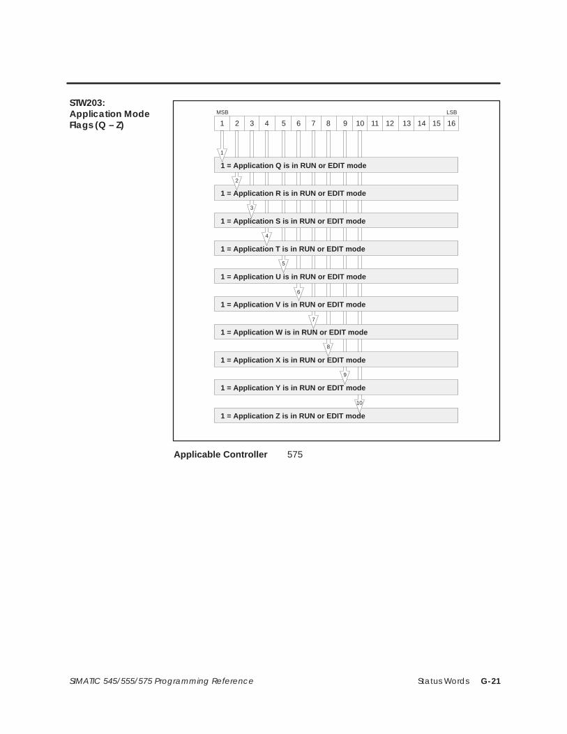
Status Words G-21SIMATIC 545/555/575 Programming Reference
1 = Application Q is in RUN or EDIT mode
1 = Application S is in RUN or EDIT mode
1 = Application R is in RUN or EDIT mode
1 = Application U is in RUN or EDIT mode
1 = Application T is in RUN or EDIT mode
1 = Application W is in RUN or EDIT mode
1 = Application V is in RUN or EDIT mode
1 = Application X is in RUN or EDIT mode
MSB LSB
1 = Application Y is in RUN or EDIT mode
1 = Application Z is in RUN or EDIT mode
1
2
3
4
5
6
7
8
9
10
16151413121110987654321
Applicable Controller 575
STW203:Application ModeFlags (Q – Z)

Status WordsG-22 SIMATIC 545/555/575 Programming Reference
1 = Application A is installed
1 = Application C is installed
1 = Application B is installed
1 = Application E is installed
1 = Application D is installed
1 = Application G is installed
1 = Application F is installed
1 = Application H is installed
MSB LSB
1 = Application I is installed
1 = Application K is installed
1 = Application J is installed
1 = Application M is installed
1 = Application L is installed
1 = Application O is installed
1 = Application N is installed
1 = Application P is installed
1
2
3
4
5
6
7
8
9
10
11
12
13
14
15
16
16151413121110987654321
Applicable Controller 575
STW204:ApplicationInstalled Flags(A – P)
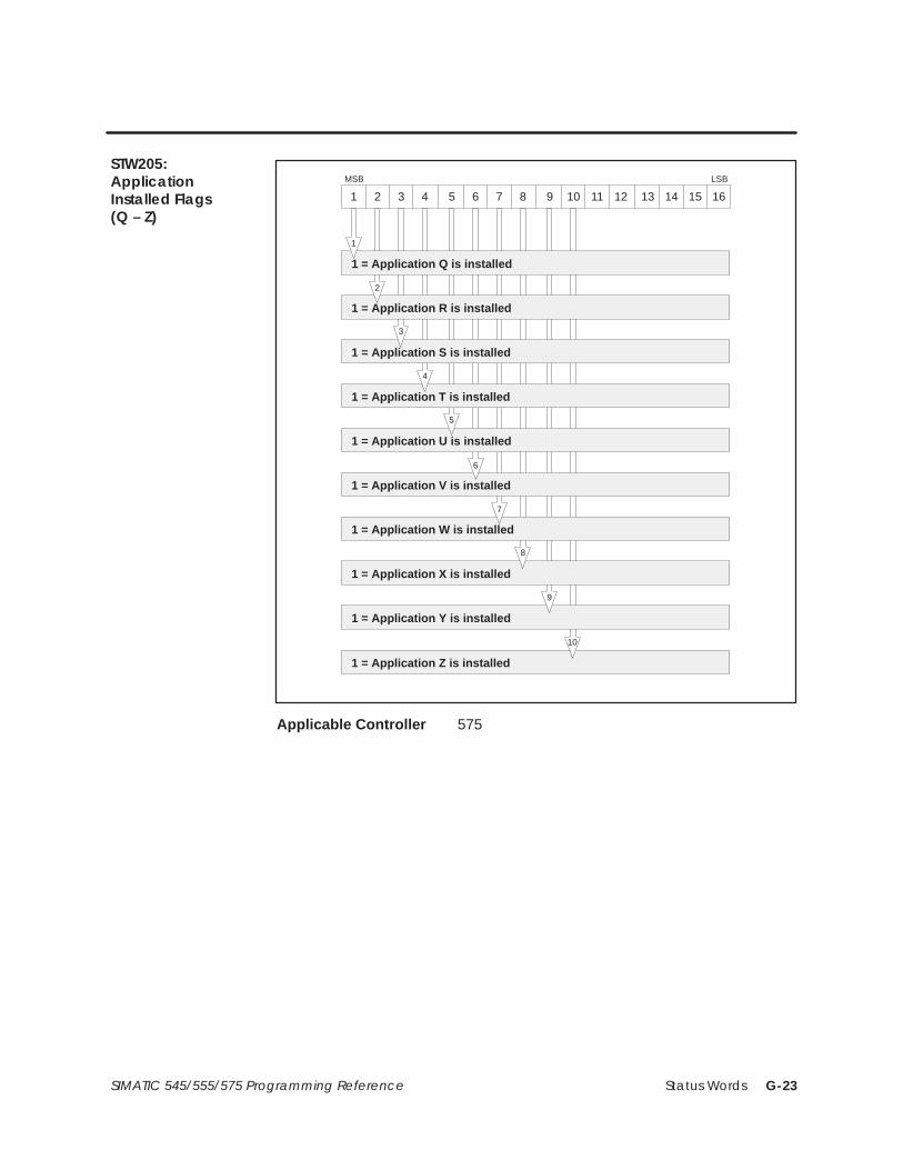
Status Words G-23SIMATIC 545/555/575 Programming Reference
1 = Application Q is installed
1 = Application S is installed
1 = Application R is installed
1 = Application U is installed
1 = Application T is installed
1 = Application W is installed
1 = Application V is installed
1 = Application X is installed
MSB LSB
1 = Application Y is installed
1 = Application Z is installed
1
2
3
4
5
6
7
8
9
10
16151413121110987654321
Applicable Controller 575
STW205:ApplicationInstalled Flags(Q – Z)

Status WordsG-24 SIMATIC 545/555/575 Programming Reference
U-Memory checksum C0 MSW
MSB LSB
16151413121110987654321
STW206
U-Memory checksum C0 LSWSTW207
Applicable Controller ALL
U-Memory checksum C1 MSW
MSB LSB
16151413121110987654321
STW208
U-Memory checksum C1 LSWSTW209
Applicable Controller ALL
STW206 – STW207:U-MemoryChecksum C0
STW208 – STW209:U-MemoryChecksum C1

Status Words G-25SIMATIC 545/555/575 Programming Reference
Base 15: 0 = Base cannot be polled; 1 = Base can be polled
Base 13: 0 = Base cannot be polled; 1 = Base can be polled
Base 14: 0 = Base cannot be polled; 1 = Base can be polled
Base 11: 0 = Base cannot be polled; 1 = Base can be polled
Base 12: 0 = Base cannot be polled; 1 = Base can be polled
Base 9: 0 = Base cannot be polled; 1 = Base can be polled
Base 10: 0 = Base cannot be polled; 1 = Base can be polled
Base 8: 0 = Base cannot be polled; 1 = Base can be polled
MSB LSB
Base 7: 0 = Base cannot be polled; 1 = Base can be polled
Base 5: 0 = Base cannot be polled; 1 = Base can be polled
Base 6: 0 = Base cannot be polled; 1 = Base can be polled
Base 3: 0 = Base cannot be polled; 1 = Base can be polled
Base 4: 0 = Base cannot be polled; 1 = Base can be polled
Base 1: 0 = Base cannot be polled; 1 = Base can be polled
Base 2: 0 = Base cannot be polled; 1 = Base can be polled
Base 0: 0 = Base cannot be polled; 1 = Base can be polled
1
2
3
4
5
6
7
8
9
10
11
12
13
14
15
16
16151413121110987654321
Applicable Controller ALL
STW210:Base Poll EnableFlags

Status WordsG-26 SIMATIC 545/555/575 Programming Reference
16151413121110987654321Bit
STW211 16 15 14 13 12 11 10 9 8 7 6 5 4 3 2 1
STW212 32 31 30 29 28 27 26 25 24 23 22 21 20 19 18 17
STW213 48 47 46 45 44 43 42 41 40 39 38 37 36 35 34 33
STW214 64 63 62 61 60 59 58 57 56 55 54 53 52 51 50 49
STW215 80 79 78 77 76 75 74 73 72 71 70 69 68 67 66 65
STW216 96 95 94 93 92 91 90 89 88 87 86 85 84 83 82 81
STW217 112 111 110 109 108 107 106 105 104 103 102 101 100 99 98 97
MSB LSB
STW211 through STW217 indicate the enable status for PROFIBUS-DPslaves. The slave’s bit, as indicated in the cells above, is a 1 if the slave isdefined and enabled.
Binary number represents an integer 1 – 26 = Application A – Z.
MSB LSB
Application ID :
1 Application A . .26 Application Z
16151413121110987654321
Applicable Controller 575
Task 1: 0 = Status good; 1 = T ask scan cycle overrun
Task 2: 0 = Status good; 1 = T ask scan cycle overrun
MSB LSB
1
2
16151413121110987654321
Applicable Controller ALL
STW211 – STW217:PROFIBUS-DP SlaveEnable Flags
STW218:My Application ID
STW219: RLL TaskOverrun

Status Words G-27SIMATIC 545/555/575 Programming Reference
S1S2S3S4S5S6S7S8S9S10S11S12S13S14S15S16
MSB LSB
16151413121110987654321
Sx = local base slot number
1 = interrupt request active at module located in this slot
Applicable Controller 545 and 555
Binary integer: 0 – 65,535, counts number of interrupt requests
MSB LSB
16151413121110987654321
STW221 is a 16-bit integer (0 – 65,535) that is incremented each time aninterrupt request is received from any interrupting module installed in thelocal base.
Applicable Controller 545 and 555
Binary integer: 0 – 65,535, counts number of spurious interrupts
MSB LSB
16151413121110987654321
STW222 is a 16-bit integer (0 – 65,535) that is incremented each time aspurious interrupt occurs. A spurious interrupt is a VMEbus interrupt thatis removed before the 575 can acknowledge it.
Applicable Controller 575
STW220:Interrupting Slots inLocal Base
STW221: ModuleInterrupt RequestCount
STW222: SpuriousInterrupt Count

Status WordsG-28 SIMATIC 545/555/575 Programming Reference
Time of Day represented in binary milliseconds MSW
MSB LSB
16151413121110987654321
STW223
Time of Day represented in binary milliseconds LSWSTW224
Day relative to 1-January-1984 represented in binarySTW225
Applicable Controller ALL
STW223 and STW224 contain a 32-bit binary representation of the relativemillisecond of the current day. STW225 contains a 16-bit binaryrepresentation of the current day relative to 1-January-1984, (day 0).See also the following description of Time-of-Day Status for STW226.
1 = Current time is prior to time reported on last T ask 1 RLL scan
1 = Time synchronization is over a network
1 = Time is valid (has been set)
1 = Time resolution
1 = No time synchronization input from the time transmitter
1 = Time Synchronization Error . Time synchronization did notoccur by the scheduled time
MSB LSB
1
10
11
12 13
14
15
16151413121110987654321
00 = 0.001 sec, 01 = 0.01 sec, 10 = 0.1 sec, 11 = 1.0 sec
Applicable Controller ALL
STW223 – STW225:Binary Time-of-Day
STW226:Time-of-Day Status

Status Words G-29SIMATIC 545/555/575 Programming Reference
STW226 contains a 16-bit representation of the Time-of-Day status.
If you use the time update feature of the SINEC H1 CommunicationsProcessor (PPX–505–CP1434TF), you should consider the following inspecifying the communications processor’s update time interval.
• Time updates from the communications processor result in thecontroller’s time of day clock being written with the new time value.This results in a minor (<1 ms) scan time extension on the scan inwhich the update occurs.
• Between time updates, the time of day is reported based on thecontroller’s time of day clock. This clock may drift (loose or gain time)relative to the SINEC H1 time source. Because of this time drift, thetime reported on the controller scan following a time update from thecommunications processor may be before the time reported onthe previous controller scan. Time status (STW226) bit 1 will indicatethis occurrence.
NOTE: The programmable controller hides negative (to the past) clockchanges due to time synchronization if the change is less than 50 ms. Forsuch a change, the controller freezes the time of day until the updated timecatches up to the controller’s time when the update was received.

Status WordsG-30 SIMATIC 545/555/575 Programming Reference
Bus error access address MSW
MSB LSB
16151413121110987654321
STW227
Bus error access address LSWSTW228
Applicable Controller 575
STW227 and STW228 contain a 32-bit binary representation of the VMEbusaddress of the first data access that was aborted due to a bus time out. Usethem with STW1, STW200, and STW229-230 to diagnose user programmingerrors on a 575 system.
NOTE: For the 575, the most significant 8 bits of the VMEbus address are0116 for a normal (VMM) address space access, or F016 for a short (VMS)address space access. The remaining 24 bits of the address contain theaddress space offset.
Bus error program offset MSW
MSB LSB
16151413121110987654321
STW229
Bus error program offset LSWSTW230
Applicable Controller 575
STW229 and STW230 contain a 32-bit binary representation the programoffset. If a VMEbus access was aborted while executing an XSUB routine,these status words contain the U-Memory offset of the instruction thatcaused the aborted VMEbus access. Use them with STW1, STW200, andSTW227-228 to diagnose user programming errors on a 575 system.
STW227 – STW228:Bus Error AccessAddress
STW229 – STW230:Bus Error ProgramOffset

Status Words G-31SIMATIC 545/555/575 Programming Reference
1 = DP I/O Bus System is not configured
1 = DP I/O in OPERATE state
1 = DP I/O in CLEAR state
MSB LSB
1
2
16151413121110987654321
16
16151413121110987654321Bit
STW232 16 15 14 13 12 11 10 9 8 7 6 5 4 3 2 1
STW233 32 31 30 29 28 27 26 25 24 23 22 21 20 19 18 17
STW234 48 47 46 45 44 43 42 41 40 39 38 37 36 35 34 33
STW235 64 63 62 61 60 59 58 57 56 55 54 53 52 51 50 49
STW236 80 79 78 77 76 75 74 73 72 71 70 69 68 67 66 65
STW237 96 95 94 93 92 91 90 89 88 87 86 85 84 83 82 81
STW238 112 111 110 109 108 107 106 105 104 103 102 101 100 99 98 97
MSB LSB
STW232 through STW238 indicate the PROFIBUS-DP slaves that havesignaled a diagnostic that has not been read by an RSD instruction (seepage 6-120). The slave’s bit, as indicated in the cells above, is a 1 if adiagnostic has been signaled and not yet read.
STW231PROFIBUS-DP I/OSystem Status
STW232 – STW238:PROFIBUS-DP SlaveDiagnostic

Status WordsG-32 SIMATIC 545/555/575 Programming Reference
CS-Memory checksum C0 MSW
MSB LSB
16151413121110987654321
STW239
CS-Memory checksum C0 LSWSTW240
Applicable Controller PowerMath CPUs only
CS-Memory checksum C1 MSW
MSB LSB
16151413121110987654321
STW241
CS-Memory checksum C1 LSWSTW242
Applicable Controller PowerMath CPUs only
STW239 – STW240:CS-MemoryChecksum C0
STW241 – STW242:CS-MemoryChecksum C1

External Subroutine Development H-1SIMATIC 545/555/575 Programming Reference
Appendix H
External Subroutine Development
H.1 Designing the External Subroutine H-2. . . . . . . . . . . . . . . . . . . . . . . . . . . . . . . . . . . . . . . . . . . . . . . . Program Code Requirements H-2. . . . . . . . . . . . . . . . . . . . . . . . . . . . . . . . . . . . . . . . . . . . . . . . . . . . Loading the Subroutine H-3. . . . . . . . . . . . . . . . . . . . . . . . . . . . . . . . . . . . . . . . . . . . . . . . . . . . . . . . .
H.2 U-Memory Format H-4. . . . . . . . . . . . . . . . . . . . . . . . . . . . . . . . . . . . . . . . . . . . . . . . . . . . . . . . . . . . . . Header H-4. . . . . . . . . . . . . . . . . . . . . . . . . . . . . . . . . . . . . . . . . . . . . . . . . . . . . . . . . . . . . . . . . . . . . . . . Code and Constant Data H-5. . . . . . . . . . . . . . . . . . . . . . . . . . . . . . . . . . . . . . . . . . . . . . . . . . . . . . . Modifiable Data H-5. . . . . . . . . . . . . . . . . . . . . . . . . . . . . . . . . . . . . . . . . . . . . . . . . . . . . . . . . . . . . . . . User Stack H-5. . . . . . . . . . . . . . . . . . . . . . . . . . . . . . . . . . . . . . . . . . . . . . . . . . . . . . . . . . . . . . . . . . . . . .
H.3 Guidelines for Creating C Language Subroutines H-6. . . . . . . . . . . . . . . . . . . . . . . . . . . . . . . . . Debugging the External Subroutine H-6. . . . . . . . . . . . . . . . . . . . . . . . . . . . . . . . . . . . . . . . . . . . . . Static Data Initialization H-7. . . . . . . . . . . . . . . . . . . . . . . . . . . . . . . . . . . . . . . . . . . . . . . . . . . . . . . . . Accessing Discrete/Word Variables H-10. . . . . . . . . . . . . . . . . . . . . . . . . . . . . . . . . . . . . . . . . . . . . . Floating Point Operations H-11. . . . . . . . . . . . . . . . . . . . . . . . . . . . . . . . . . . . . . . . . . . . . . . . . . . . . . . Unsupported C Language Features H-11. . . . . . . . . . . . . . . . . . . . . . . . . . . . . . . . . . . . . . . . . . . . . .
H.4 Developing an External Subroutine — Example H-12. . . . . . . . . . . . . . . . . . . . . . . . . . . . . . . . . . . Example Header File H-12. . . . . . . . . . . . . . . . . . . . . . . . . . . . . . . . . . . . . . . . . . . . . . . . . . . . . . . . . . . . Example Subroutine Source H-14. . . . . . . . . . . . . . . . . . . . . . . . . . . . . . . . . . . . . . . . . . . . . . . . . . . . . Preparing the Load Module H-14. . . . . . . . . . . . . . . . . . . . . . . . . . . . . . . . . . . . . . . . . . . . . . . . . . . . . Loading U-Memory H-16. . . . . . . . . . . . . . . . . . . . . . . . . . . . . . . . . . . . . . . . . . . . . . . . . . . . . . . . . . . . . Using the External Subroutines in RLL H-16. . . . . . . . . . . . . . . . . . . . . . . . . . . . . . . . . . . . . . . . . . . . .

External Subroutine DevelopmentH-2 SIMATIC 545/555/575 Programming Reference
H.1 Designing the External Subroutine
! WARNINGWhen you call an external subroutine, the built-in protection features of thecontroller are by-passed. Use care when you test the external subroutine beforeintroducing it to a control environment.
Failure to do so may cause undetected corruption of controller memory andunpredictable operation by the controller , which could result in death or seriousinjury to personnel, and/or damage to equipment.
You must take care in testing the external subroutine before introducing it to acontrol environment.
Follow these rules when you develop an external subroutine.
• Use a compiler, such as Microtec� MCC68K, that allows generation ofposition independent code targeted as follows:
For the 545/555: Motorola� 68020.For the 575: Motorola 68020 and optionally, the 68881 or the 68882floating-point processor, if installed.
The object code must be position-independent, i.e., it must usePC-relative addresses for all references to programs and data containedin U-Memory.
• Link all subroutines into one downloadable load module in MotorolaS-Record format. The resulting file must conform to the formatspecified in Section H.2.
• To help ensure that the subroutine interacts correctly and safely withthe controller program, follow the guidelines in Section H.3 as youdevelop an external subroutine for your application.
Program CodeRequirements

External Subroutine Development H-3SIMATIC 545/555/575 Programming Reference
Follow these steps to prepare the external subroutine for use in thecontroller.
1. Compile/assemble the subroutines and header to create object modules.
2. Link the object modules for the header and subroutines to create theload module. The file name must have the extension .rec. The outputmust have the header at zero followed by the code and data constants,then the variables, and finally the stack.
3. Use TISOFT to configure U-Memory, if you have not already done so.
4. Use the TISOFT Convert S-Records option (AUX 40) to import thelinked program into the TISOFT environment.
5. Use the TISOFT Load U-Memory option (AUX 43) to load the filecreated in step 4 into U-Memory.
An example application illustrating this process is given in Section H.4.
Loading theSubroutine

External Subroutine DevelopmentH-4 SIMATIC 545/555/575 Programming Reference
H.2 U-Memory Format
External subroutines are stored in U-Memory. U-Memory consists of fourlogical segments, described below, and illustrated in Figure H-1.
The header contains the following data elements, that must be defined inthe order specified.
E/Version This 16-bit word contains two data elements:
• Bit 1 (the MSB) specifies the error action taken in the event of a buserror while accessing the VMEbus in an XSUB routine on a 575. If bit 1is a 0 and a VMEbus error occurs while processing an XSUB, thecontroller enters the Fatal Error mode. If bit 1 is a 1, and a VMEbuserror occurs while processing an XSUB, the XSUB’s executionterminates, bits 6 and 11 of STW1 are set, and STW200 is set to 7 (ifthis is the first error encountered on this RLL scan). The controllerstays in RUN mode. This bit is ignored by 545 and 555.
• Bits 2 through 16 specify the header version number. It must have abinary value of 1 or the U-Memory load operation (TISOFT AUXfunction 43) fails.
Num_XSUBs Specifies the number of external subroutines defined in theload module. This element is a 16-bit word.
Data_Start Specifies the U-Memory offset for the beginning of themodifiable data area. This element is a 32-bit long word.
Stack_Start Specifies the U-Memory offset to the lowest U-Memorylocation available for use as a run-time stack. The block of memory fromthis location to the end of U-Memory is available to the main RLL task(TASK1) during XSUB calls. This element is a 32-bit long word.
NOTE: For an XSUB called by the cyclic or interrupt RLL tasks (TASK2 orTASK8), the stack is allocated by the operating system and is relativelysmall ( approximately 500 bytes).
Stack_Size Specifies the minimum number of bytes that must beavailable for use as the run-time stack area when an external subroutine iscalled by the main RLL task. This element is a 32-bit long word.
Entry_Points This is a table containing n 32-bit elements, where nequals the number of subroutines, as specified in Num_XSUBs. Each elementin this table specifies the U-Memory offset for the entry point of each of thesubroutines 1 through n, respectively. A value of 0 indicates that thespecified subroutine is not present.
Header

External Subroutine Development H-5SIMATIC 545/555/575 Programming Reference
The code and constant data area immediately follow the header area. Thisarea consists of position-independent, invariant machine code, and dataconstants.
The modifiable data area follows the code and constant data area andcontains the static variables used by the subroutines.
The user stack follows the modifiable data area in U-Memory. The size ofthe user stack depends upon the configured size of U-Memory and howmuch memory is used by the header, the code and constant data, and themodifiable data areas. The user stack starts at the last location ofU-Memory and grows downwards, toward the address specified byStack_Start. Stack_Size specifies the minimum size of this area.
Data_Start: U-Memory offset to modifiable data
Stack_Start: U-Memory offset to user stack
Stack_Size: Size of user stack
Entry_Points(1): U-Memory offset to subroutine 1
Entry_Points(2): U-Memory offset to subroutine 2
Header Version
Entry_Points(n): U-Memory offset to subroutine n
Code and constant data: Contains fully resolved, position-independentsubroutine executables and constant data.
Modifiable data: Static variables used by the subroutines.
User Stack: The user stack starts at the last location of U-Memory and growstoward the location referenced by Stack_Start.
Num_XSUBs: Number of Subroutines
Hea
der
Bit *1 16 17 32
Long Word
* The bit numbering shown is consistent with the long word format described in Chapter 2.The processor numbering is 31–0, corresponding to 1–32, respectively.
E2
Figure H-1 Externally Developed Subroutine Code Format
NOTE: When U-Memory is loaded, the system verifies that sufficientU-Memory is configured to hold the header, code, data, and stack. The loadis rejected unless there is enough memory. A subsequent attempt toreconfigure loaded U-Memory to a size less than the sum of header, code,data, and stack is also rejected.
Code andConstant Data
Modifiable Data
User Stack

External Subroutine DevelopmentH-6 SIMATIC 545/555/575 Programming Reference
H.3 Guidelines for Creating C Language Subroutines
The guidelines in this section can answer some questions that may arise asyou develop your code. These guidelines assume that you are using theMicrotec MCC68K tool set. Version 4.2A of this compiler has been tested ina limited number of 545 and 575 applications and has been verified togenerate code that reliably runs on these machines. MCC68K runs on IBMcompatible personal computers, as well as a number of minicomputers andwork stations. The MCC68K tool set is available from:
Microtec Research, Inc.2350 Mission College Blvd.Santa Clara, CA 95054Toll Free 800.950.5554
If you are using a different compiler, you need to make changes in theseguidelines to fit that compiler’s requirements.
Facilities for debugging external subroutines on the controller are verylimited. It is strongly recommended that you develop and test your externalsubroutines using a native compiler on your development computer. Anumber of C compilers are available commercially for this purpose,including Quick C� and Turbo C� for the MS-DOS� environment.
Before coding the external subroutine, be aware that compiler differencesmay exist between the native compiler on the development computer andthe MCC68K compiler. A native compiler, designed for use on a generalpurpose system, e.g., the IBM PC/AT, usually has a larger set of runtimefacilities than does a compiler like MCC68K, that is designed for embeddedsystems. If you use these facilities, they will not exist when you port yourexternal subroutines to the controller.
After you have written and debugged your subroutines on the developmentcomputer, you must port the debugged subroutines to the controller. If youavoid architectural features of the development machine, and if you havenot used runtime elements from the native compiler that are not present inMCC68K, then this is a straight forward procedure.
Before attempting to control an actual process, always check the subroutinein a test environment (on a controller that is not connected to a factory-floorprocess) to verify that the subroutine and controller program operate asexpected.
Debugging theExternal Subroutine

External Subroutine Development H-7SIMATIC 545/555/575 Programming Reference
In C, variables declared outside of functions or declared with the staticattribute are initialized when the program starts, just before entering themain procedure. When you write external subroutines you do not have amain procedure and the normal initialization does not occur. Therefore, youneed to assign one of your subroutines to perform the C initializationfunction. This subroutine must be called from the main RLL task wheneveryour application is (re)started, e.g., at power-up or a transition fromPROGRAM to RUN mode.
Assembly subroutine vinit.src * (Figure H-2) contains the necessaryinitialization routine for version 4.2A of MCC68K. Include the initializationsubroutine as XSUB1 in all U-Memory load modules. You should callXSUB1 whenever your RLL performs its startup initialization. Subroutine_vinit (XSUB1) must be called before any static variables are referenced byyour external subroutines.
* The VINIT routine is based in part on INITCOPY.C, Copyright (C) 1990,Microtec Research, Inc.
Static DataInitialization

External Subroutine DevelopmentH-8 SIMATIC 545/555/575 Programming Reference
Guidelines for Creating C Language Subroutines (continued)
TTL _VINIT –– Initialize Static Variables OPT CASE
*===============================================================================* function _vinit –– Initialize Static Variables.** * SYNOPSIS:** void _vinit (long int * code);** where code is:** 0 if initialization was successful.* 1 if initialization failed due to invalid start code in ??INITDATA.* 2 if initialization failed due to unknown flag byte in a copy* specification.* * * DESCRIPTION:** This function may be called as an external subroutine in order to * initialize all static variables declared by the U Memory load module.** Subroutine _vinit zeroes all ”zerovars” variables and sets all ”vars” * variables to their specified initial values. A ”zerovars” variable* is a variable declared using statements of the form:** [static] int var;** A ”vars” variable is a variable declared using statements of the form:** [static] int var = 5;** External subroutine _vinit must be called before any other external* subroutine. It should be called once whenever the RLL process is * started or restarted.** * ASSUMPTIONS:** This subroutine assumes the Microtec C compiler has been used to create* the objects comprising the load module and that the Microtec linker* has been used with (at least) the ”INITDATA vars” command. It also* assumes that the U Memory header is the first element of section ”const”* and is located at U Memory offset 0.** The structure of section ??INITDATA (created by the Microtec linker) is * as follows. Byte 0 contains an ’S’ indicating start of ??INITDATA. * This byte is followed by zero or more copy specifications (see below). * The last copy specification is followed by an ’E’ indicating the end * of the ??INITDATA section.** A copy specification has four fields:** flag One byte containing a ’C’, indicating start of copy specification;* length Four bytes containing the length (in bytes) of the <data> field;* dest Four bytes containing the starting U–Memory offset to which the* <data> field is to be copied;* data The values to be copied to <dest>. The length of this field is * specified by the <length> field.**===============================================================================
Figure H-2 Initialization Routine Required for Microtec C

External Subroutine Development H-9SIMATIC 545/555/575 Programming Reference
**** Initialize the ’zerovars’ section to all 0.* SECTION code,,C int __vinit () XDEF __vinit {__vinit LEA .startof.(zerovars)(PC),A0 ptr1 = address of zerovars; MOVE.L #.sizeof.(zerovars),D0 length = size of zerovars; BRA.S LOOP00S while (––length >= 0) {LOOP00 CLR.B (A0)+ *ptr1 = 0;LOOP00S SUBQ.L #1,D0 } BHS LOOP00 .
**** Copy initial values from the ??INITDATA section (constructed by the* linker due to the INITDATA command) to the appropriate destination* address.* MOVE.L #.sizeof.(??INITDATA),D0 if (??INITDATA not empty) SUBQ.L #2,D0 . BLO.S ENDIF10 { LEA .startof.(??INITDATA)(PC),A0 ptr1 = address of ??INITDATA CMPI.B #’S’,(A0)+ error if (*ptr1++ != ’S’) BNE.S ERROR1 .LOOP20 MOVE.B (A0)+,D0 while ((t = *ptr1++) != ’E’) CMPI.B #’E’,D0 . BEQ.S ELOOP20 { CMPI.B #’C’,D0 error if (t != ’C’) BNE.S ERROR2 . MOVE.L (A0)+,D0 length = *((long *) ptr1); LEA .startof.(const)(PC),A1 ptr2 = address_of (header) ADDA.L (A0)+,A1 . + *((long *) ptr1); BRA.S LOOP30S while (––length >= 0) {LOOP30 MOVE.B (A0)+,(A1)+ *dest++ = *source++;LOOP30S SUBQ.L #1,D0 } BHS LOOP30 . BRA LOOP20 }ELOOP20 EQU * .ENDIF10 EQU * } MOVEQ #0,D0 code = no error;
**** Return the value of <code> to the user.*GOBAK MOVEA.L 4(SP),A0 return (code); MOVE.L D0,(A0) . RTS .
**** Error handlers:*ERROR1 EQU * error1: MOVEQ #1,D0 code = no starting point; BRA GOBAK return (code);
ERROR2 EQU * error2: MOVEQ #2,D0 code = unknown flag byte; BRA GOBAK return (code); END ! };
Figure H-2 Initialization Routine Required for Microtec C (continued)

External Subroutine DevelopmentH-10 SIMATIC 545/555/575 Programming Reference
Guidelines for Creating C Language Subroutines (continued)
As specified in Section 6.81, the calling conventions used by the XSUBinstruction always pass 32-bit values or pointers to the external subroutine.
When passing a discrete value, e.g., IN X5, the on/off state of the parameteris in the least significant bit of the 32-bit value. Other bits are unspecified.The example in Figure H-3 shows one way to isolate the actual value of thediscrete parameter.
void sub1 (long int D, ...){
unsigned char D_value;D_value = D & 0x1;...
}
Figure H-3 Example of Passing a Discrete Value
When passing a pointer to a discrete variable, e.g., IO X5, you must declarethe data type of the parameter as an unsigned char pointer. The discretevalue is in the least significant bit of the 8-bit value addressed by thepointer. Refer to the example in Figure H-4.
void sub2 (unsigned char *D, ...){
if (*D & 0x1)... handle case where parameter is on (true) ...else... handle case where parameter is off (false)
}
Figure H-4 Example of Passing a Pointer
When passing a normal value, e.g., IN V103, the value is assumed to occupy along word (V103 and V104). If only a word is required, you must includecode to isolate this word from the most significant 16 bits of the value. Seethe example in Figure H-5.
void sub3 (long int V, ...){
short int V_value;V_value = V >>16;...}
Figure H-5 Example of Passing Normal Values
AccessingDiscrete/WordVariables

External Subroutine Development H-11SIMATIC 545/555/575 Programming Reference
When passing a pointer to a normal variable, e.g., IO V15, you control thedata element type since you completely declare the data type in yourC Language function.
! CAUTIONFor the 575 controller , word image register values can only be accessed aswords or long words.
If you access a word image register location as a byte (8 bits), the result isunspecified, and could cause damage to equipment,
Ensure that you always use words or long words with the 575 controller .
NOTE: The controller allows pointers to read-only variables (STW, K, X) tobe passed to external subroutines. It is recommended that you not designthe subroutine to alter the content of these variables since otherinstructions assume that the content does not change.
The controller uses single precision floating-point math. The default type forfloating-point constants and operations in the MCC68K compiler is doubleprecision. On the 545, 555, and 575 without a math coprocessor, you maywant to avoid the overhead associated with double precision math. Refer toyour compiler’s documentation for instructions for forcing single precisionmath.
Do not use operating system-dependent language elements in externalsubroutines. This includes the C Language runtime routines listed below.Refer to your compiler’s documentation for possible additionalOS-dependent runtime.
clearerr feof fopen fsacnf lseek puts ungetc
close ferror fprintf fwrite open read
create fflush fputc getc printf setbuf
_exit fgetc fputs getchar putc scanf
fclose fgets fread gets putchar sprintf
Floating PointOperations
UnsupportedC LanguageFeatures

External Subroutine DevelopmentH-12 SIMATIC 545/555/575 Programming Reference
H.4 Developing an External Subroutine — Example
This section illustrates the creation of a U-Memory load module that definestwo external subroutines: long_add (XSUB2) and long_subtract (XSUB3).The example was developed with the MS-DOS version of MCC68K.
The header.src file (Figure H-6) defines the U-Memory header for theexample application. When the header is linked with the initializationroutine and the application-specific subroutine file, the header must beplaced at location 0 of the load module. Additionally, all code and dataconstants must be loaded before any variables (zerovars and vars), whichmust be loaded before the stack section. See the sample link command file inFigure H-9.
TTL HEADER –– U–Memory header for sample application.
*===============================================================================* HEADER.SRC –– U–Memory header for sample application.** * DESCRIPTION:** File HEADER.SRC contains the definition for the U Memory header required* for the sample XSUB application. This file is written in the Microtec* ASM68K assembly language. The object from this file must be loaded at* relative address 0 of the U Memory load image.**=============================================================================== OPT CASE Labels are case sensitive SECTION const,,R Header must be first in <const> section DC.W 1 Header version is 1 for rel 2.x DC.W NUM_SUB Number of subroutine entry points DC.L .startof.(zerovars) Start of modifiable variables DC.L .startof.(stack) Lowest address for valid stack pointer XREF STACKSIZE Size of stack (defined at link time) DC.L STACKSIZEEP_TBL EQU * Entry point table XREF __vinit XSUB1 initializes static variables DC.L __vinit . XREF _long_add XSUB2 performs a long integer ADD DC.L _long_add . XREF _long_subtract XSUB3 performs a long integer SUB DC.L _long_subtractNUM_SUB EQU (*–EP_TBL)/4 Computes number of entry points END
Figure H-6 Example Assembly Language Header File
Example HeaderFile

External Subroutine Development H-13SIMATIC 545/555/575 Programming Reference
The header.src file contains pointers to the base of the zerovars and stacksections, and to external entry points __vinit, _long_add, and _long_subtract.Note that the subroutine entry point names are preceded with anunderscore. This is a C Language requirement. During execution, thesepointers are used by the controller’s operating system as offsets relative tothe start of U-Memory.
! WARNINGOther than the header, external subroutines should not define or use staticpointers.
Use of invalid pointers is likely to cause unpredictable operation that couldresult in death or serious injury to personnel, and/or damage to equipment.
Pointers passed as parameters on a given subroutine call may be invalidated ifyou reconfigure user memory .
! WARNINGDo not change any portion of the U-Memory content loaded in front of the baseaddress of zerovars after the U-Memory load. Otherwise, the controller entersthe FATAL ERROR mode due to a U-Memory checksum violation, turns offdiscrete outputs and freezes analog outputs.
This could cause unpredictable operation of the controller that could result indeath or serious injury to personnel, and/or damage to equipment.
Only properly trained personnel should work on programmablecontroller-based equipment.

External Subroutine DevelopmentH-14 SIMATIC 545/555/575 Programming Reference
Developing an External Subroutine — Example (continued)
Depending on the complexity of your application, the subroutine source maybe a single file or several files. Figure H-7 shows file xsubs.c, which definesthe application-specific subroutines comprising the example. Theinitialization routine is contained in file vinit.src (Figure H-2).
/*Procedure long_add: Compute the sum of two long words *//* and store the result in a third *//* long word. */
void long_add (long addend_1, long addend_2, long *sum){
*sum = addend_1 + addend_2;return;
}/* Procedure long_subtract: Subtract one long word from a *//* second long word and store the *//* result in a third long word. */
void long_subtract (long minuend, long subtrahend, long *difference){
*difference = minuend – subtrahend;return;
}
Figure H-7 Example Subroutine Source File
Figure H-8 shows the MS-DOS commands required to create a MotorolaS-record load module for the example.
• The first two commands assemble header.src and vinit.src, producingobject files header.obj and vinit.obj, respectively.
• The third command compiles xsubs.c, producing object file xsubs.obj.Compiler options force the compiler to generate PC-relative code (–Mcp)and data (–Mdp) references. These options are mandatory. They ensurethat the resulting load module is position-independent. The –c optioninstructs MCC68K to create an object module without invoking thelinker.
• The fourth command invokes the linker with command file xsubs.cmdand output file xsubs.rec. The .rec extension is required by TISOFT.
> asm68k header.src> asm68k vinit.src> mcc68k –Mcp –Mdp –c xsubs.c> lnk68k –c xsubs.cmd –o xsubs.rec
Figure H-8 Example Commands for Preparing the Load Module
ExampleSubroutine Source
Preparing the LoadModule

External Subroutine Development H-15SIMATIC 545/555/575 Programming Reference
The content of the link command file depends on the complexity of yourapplication. File xsubs.cmd shown in Figure H-9 is sufficient for theexample application. Table H-1 lists the functions of the linker commandscontained in this file.
CASEFORMAT SLISTABS NOPUBLICS,NOINTERNALSORDER const,code,strings,literals,??INITDATAORDER zerovars,vars,tags,stackINITDATA varsPUBLIC STACKSIZE=1024BASE 0LOAD header.objLOAD vinit.objLOAD xsubs.objLOAD c:\mcc68k\mcc68kpc.libEND
Figure H-9 Example Link Command File
Table H-1 Linker Command Functions
Command Description
CASE Indicates that symbols are case sensitive.
FORMAT Indicates that the linker output is to be in Motorola S-record format.
LISTABS Tells the linker to omit symbol table information from the load module.
ORDER Specifies the order in which sections are to be placed in the load image generated by the linker.
The first ORDER statement lists all sections whose content do not change after U-Memory isloaded. Section const must be named first so that the U Memory header is at 0. This is followedby the names of other invariant sections produced by the compiler and linker.
The second ORDER statement lists all sections whose content may change after U-Memory isloaded. These sections must be linked after all invariant sections. The zerovars section must benamed first and the stack section must be named last.
INITDATA Tells the linker to create a read only copy of initialized variables (section vars) in section??INITDATA. Subroutine _vinit uses this copy to initialize the actual variables in section vars.
PUBLIC Tells the linker to define variable STACKSIZE. The value on the right of the equal sign inplaced in the U-Memory header’s stack size data element.
BASE Tells the linker to link relative to address 0.
LOAD Tells the linker which modules are to be included in the load module. Name the header file(header.obj) first. You can load other modules in any order.
File C:\mcc68k\68020\mcc68kpc.lib is the position independent run-time library forMCC68K.

External Subroutine DevelopmentH-16 SIMATIC 545/555/575 Programming Reference
Developing an External Subroutine — Example (continued)
Use the TISOFT Convert S-Records option (AUX 40) to import xsubs.rec intothe TISOFT file system; then use the TISOFT Load U-Memory option(AUX 43) to download to U-Memory.
NOTE: If you have not configured U-Memory, you must do so before TISOFTallows these functions.
When you initialize the RLL program, you must also initialize the externalsubroutine variables. Figure H-10 illustrates a call to _vinit (XSUB1), whichoccurs once, whenever control relay C1 is off. Note that the _vinit call mustspecify a single IO parameter. This parameter is written with the returncode from _vinit.
C1
IO1: V1
C1
SET
C1
XSUB1
Figure H-10 Example Subroutine Call for Static Variable Initialization
Figure H-11 illustrates an RLL network that calls the long_add subroutine.There are three parameters in the XSUB2 box. These correspond to thethree parameters in the long_add subroutine. The first parameter (IN1)corresponds to parameter addend_1 in the definition of long_add. Thesecond parameter (IN2) corresponds to addend_2, and the third parameter(IO3) corresponds to sum.
Y24
IN1: V1
IN2:
IO3:
V33
V75
XSUB2
Figure H-11 Example Call to a Subroutine
Loading U-Memory
Using the ExternalSubroutines in RLL

External Subroutine Development H-17SIMATIC 545/555/575 Programming Reference
There must be a one-to-one correspondence between parameters in theXSUB call (from top to bottom) and parameters in the subroutine definition(from left to right for C).
• Parameters one and two are IN parameters in the XSUB call. This isrequired since long_add expects addend_1 and addend_2 to be longinteger values.
• Parameter three is an IO parameter in the XSUB call. This agrees withlong_add’s definition of sum as a pointer, or address, parameter.
! WARNINGYou must ensure agreement between the XSUB call and the XSUB’ s definition inthe number and use of parameters.
If, for example, you were to specify IN for parameter three in the exampleXSUB2 call, the long_add subroutine would use the value of V75–76 as anaddress. The result, although unspecified, is likely to be a fatal error due toaccess to an undefined address or due to corruption of the controller executionenvironment.
This could cause unpredictable operation of the controller that could result indeath or serious injury to personnel, and/or damage to equipment
Only properly trained personnel should work on programmablecontroller-based equipment.

Interboard Communications for the 575 I-1SIMATIC 545/555/575 Programming Reference
Appendix I
Interboard Communications for the 575
I.1 Using Applications to Enable CPUs to Exchange Data I-2. . . . . . . . . . . . . . . . . . . . . . . . . . . . . Applications I-2. . . . . . . . . . . . . . . . . . . . . . . . . . . . . . . . . . . . . . . . . . . . . . . . . . . . . . . . . . . . . . . . . . . . Overview I-4. . . . . . . . . . . . . . . . . . . . . . . . . . . . . . . . . . . . . . . . . . . . . . . . . . . . . . . . . . . . . . . . . . . . . . . G-Memory Areas I-4. . . . . . . . . . . . . . . . . . . . . . . . . . . . . . . . . . . . . . . . . . . . . . . . . . . . . . . . . . . . . . . Required and Optional Applications I-5. . . . . . . . . . . . . . . . . . . . . . . . . . . . . . . . . . . . . . . . . . . . . Locking Mode Transitions for Two or More Applications I-6. . . . . . . . . . . . . . . . . . . . . . . . . . . .
I.2 Using Direct VMEbus Access to Communicate with Third-Party Boards I-8. . . . . . . . . . . . . Accessing VMEbus Masters and Slaves Directly I-8. . . . . . . . . . . . . . . . . . . . . . . . . . . . . . . . . . .
I.3 Coordinating Access to Shared Memory I-10. . . . . . . . . . . . . . . . . . . . . . . . . . . . . . . . . . . . . . . . . Using Locks I-10. . . . . . . . . . . . . . . . . . . . . . . . . . . . . . . . . . . . . . . . . . . . . . . . . . . . . . . . . . . . . . . . . . . . .

Interboard Communications for the 575I-2 SIMATIC 545/555/575 Programming Reference
I.1 Using Applications to Enable CPUs to Exchange Data
In the 575 system, an application is a user program that executes on asingle 575 CPU (or another CPU that conforms to the SIMATIC 575Interboard Communication Specification). An application on a 575 CPUconsists of the following program elements.
• RLL programs
• SF programs
• Loops
• Analog alarms
• External subroutines
Each 575 application presents an area of memory (G-Memory) to theVMEbus. G-Memory allows CPUs and intelligent I/O to exchange data overthe VMEbus backplane. For example, an application within a CPU can readdata from another application and write data back to that application. SeeFigure I-1.
Application A Application B
G-Memoryareareserved forapplication A
G-Memoryareareserved forapplication B
GA1throughGA32768
GB1throughGB32768
Application A canaccess theG-Memory areareserved forapplication B
Application B canaccess theG-Memory areareserved forapplication A
RLL programSF programloopsanalog alarms
CPU
VME backplane
CPU
RLL programSF programloopsanalog alarms
Figure I-1 Typical CPU Application
Applications

Interboard Communications for the 575 I-3SIMATIC 545/555/575 Programming Reference
Boards can work together to control a process by communicating throughtheir G-Memory areas. Using G-Memory, you can do the following tasks:
• Exchange data between applications without being aware of thephysical addresses of the application’s memory.
• Set locks so that one application can manipulate data in specificG-Memory locations without having those locations accessed by anotherapplication at the same time.
• Synchronize applications so that they initialize status words at thesame time.
• Share data in memory instead of over the communication network. Thispractice allows data to be shared quickly and efficiently.

Interboard Communications for the 575I-4 SIMATIC 545/555/575 Programming Reference
Using Applications to Enable CPUs to Exchange Data (continued)
Each application uses G-Memory to make data available to otherapplications. G-Memory resides on the VMEbus, and consists of up to 26separate memory areas, totalling 32 Kwords. These areas are accessed byusing the G-Memory addresses GAn through GZn (n is a value from 1 to32768). See Figure I-2.
G-Memory
GA1 through GA32768
GB1 through GB32768
GC1 through GC32768
GX1 through GX32768
GY1 through GY32768
GZ1 through GZ32768
RLL Program in Application AApplication
CPUApplication A
MOVW1
K1GC25
MOVW1
GZ10V100
Moves a constant from K1 toG-Memory location GC25.
Moves a word from G-Memorylocation GZ10 to V100.
X4 C2
C2 C3
X5
NOTE: These G-Memory locationsare available only if theircorresponding applications areinstalled in the base.
Figure I-2 Accessing G-Memory
Each 575 application is automatically assigned a G-Memory area. Thememory area is determined by the relationship of the board to the firstapplication inserted in the base.
Application A is assigned to the primary 575 CPU. G-Memory locations GA1through GA32768 are automatically assigned to that board. If a board is thesixth application board installed in the base, G-Memory locations GF1through GF32768 automatically belong to that board.
As long as the assignments for each of the installed applications are unique,any non-575 applications may be assigned to any of the unused applicationidentifiers (B – Z).
Overview
G-Memory Areas

Interboard Communications for the 575 I-5SIMATIC 545/555/575 Programming Reference
Applications depend on G-Memory to exchange data. Therefore, you mustdesignate whether an application is required or optional. If an application isrequired, it must be installed before the application that refers to it can goto the RUN mode. If an application is optional, it does not have to beinstalled before the application that refers to it can operate.
In order for an application to reference another application’s G-Memory, thesecond application must be installed as either required or optional.
If an optional application is installed:
• The application referring to that application can go to RUN mode.
• References to that application perform their specified function.
If an optional application is not installed:
• The application referring to that application can go to RUN mode.
• A reference to that application’s G-Memory sets error bit 6 in STW1 ifthe reference actually is executed.
• If it is the first error logged, STW200 (uninstalled application) is loggedas well.
To designate which applications are required or optional, use the REQAPPoption from the TISOFT Memory Configuration menu.
Required andOptionalApplications

Interboard Communications for the 575I-6 SIMATIC 545/555/575 Programming Reference
Using Applications to Enable CPUs to Exchange Data (continued)
You can configure CPUs so that they experience mode transitions(PROGRAM to RUN, etc.) simultaneously. When you request this function,the CPUs and their applications are mode-locked.
When you change an application from PROGRAM mode to RUN mode, allmode-locked applications change to RUN mode with it. The duration of thefirst scan is the same for all these applications, but the length of this scandoes not affect the peak scan time. This feature allows you to initializestatus words and memory so that applications do not inadvertently accesscorrupt data.
If you change a mode-locked application from RUN mode to PROGRAMmode, all mode-locked applications change to PROGRAM mode with it. SeeFigure I-3.
Application A
Application B
Scan time = 100 ms
Scan time = 27 ms
Begin transition to RUN modefrom PROGRAM mode
Begin transition to PROGRAMmode from RUN mode
1st scan
The duration of the first scan is thesame for both applications,regardless of the length of the actualscan for each application.
When a transition from RUN modeto PROGRAM mode occurs, allapplications update their I/O at thesame time, regardless of the lengthof the actual scan for eachapplication.
Mode-locked operation extendsthe scan of Application B so itsI/O are updated at the sametime as Application A.
Figure I-3 Example of Mode-locked Applications
Locking ModeTransitions for Twoor MoreApplications

Interboard Communications for the 575 I-7SIMATIC 545/555/575 Programming Reference
To mode-lock two or more applications, use TISOFT to bring up the MemoryConfiguration menu. Select REQAPP and follow the prompts.
You can perform run-time edits on mode-locked applications. If you performa run-time edit to initialize values in a mode-locked application, the editdoes not affect the other mode-locked applications, unless a compile erroroccurs, in which case all mode-locked applications go to PROGRAM mode.
If a fatal error occurs, the system transitions to the FAULT mode and shutsdown all applications. A power-up restart synchronizes the first scan of allthe 575 CPU applications, regardless of whether they are mode-locked. Ifyou try to restart a different way, the system asks you whether or not youwant mode-locked operation. You can specify which applications you want tomode-lock.

Interboard Communications for the 575I-8 SIMATIC 545/555/575 Programming Reference
I.2 Using Direct VMEbus Access to Communicate with Third-Party Boards
Most third-party boards that you can use in the 575 system do not conformto the SIMATIC 575 Interboard Communications Specification. This meansthat they do not provide application memory (G-Memory) as the means forinterboard communication. To communicate with these boards, you mustuse direct VMEbus access.
You can access VMEbus slaves and masters directly from your 575 userprogram in the ways described below. All user-program access to VMEbusA16 address space (VMS memory type) is performed using VMEbus addressmodifier 2916 (short, non-privileged access). User-program access toVMEbus A24 address space (VMM memory type) is performed usingaddress modifier 3916 (standard, non-privileged data access).
Accessing VMEbusMasters and SlavesDirectly

Interboard Communications for the 575 I-9SIMATIC 545/555/575 Programming Reference
The 575 provides the following three ways to access VMEbus addressesdirectly from your user program.
• The Move Element (MOVE) RLL instruction allows you to move bytes,words, and long-words1 to/from VMEbus memory. The MOVEinstruction provides for recovery from VMEbus access errors. Access toan invalid VMEbus location results in an instruction error beingreported to your RLL program, but the 575 does not enter FATALERROR mode.
• All word-oriented RLL instructions (e.g., ADD, SUB, MOVW, etc.) allowyou to operate on VMEbus locations. They do not, however, provide forrecovery from VMEbus access errors. If a VMEbus access error occurs,the 575 enters FATAL ERROR mode.
• You can create an external subroutine (XSUB) to perform the VMEbusaccess. You can pass the VMEbus address to the external subroutine toaccess the VMEbus by using an I/O parameter specifying VMS (A16) orVMM (A24) memory, or you can code the VMEbus address in yourexternal subroutine. If you code the address in your externalsubroutine, you must offset the VMEbus address with the appropriate“address space selector” as follows:
575 CPU address F0xxxx16 selects VMEbus A16 address xxxx16.
575 CPU address 01xxxxxx16 selects VMEbus A24 address xxxxxx16.
Refer to Chapter 6 for a complete description of these instructions.
NOTE: The VMS and VMM variable types provide access to word(even-numbered) addresses. To specify an odd byte address in RLL, youmust use the MOVE instruction, specifying an element size of byte and anodd index.
1Because the 575 is a D16 master, long-word (32-bit) VMEbus accesses are performed(physically) as two consecutive word (16-bit) accesses. This means that a long-word access maynot be atomic. It is possible for the long word to be changed (if the board is accessed) after thefirst word is read and before the second word is read. It is also possible for the long word to beread (if the board is accessed) after the first word is written and before the second word iswritten.

Interboard Communications for the 575I-10 SIMATIC 545/555/575 Programming Reference
I.3 Coordinating Access to Shared Memory
If you need to manipulate data stored in shared memory (G, VMM, or VMS)without interference from other applications, design your application tocoordinate access to the shared memory using a lock. Figure I-4 andFigure I-5 illustrate how a lock operates. In these examples, 575applications A and B are coordinating access to location GA110 using a lockthat resides in location GA2 (and GA3).
A lock can be held in either an exclusive or a shared mode. When the lock isheld in exclusive mode by an application, other applications are notified notto read from or write to the associated shared memory. When a lock is heldin shared mode by an application, other applications are notified that theycan read from the associated shared memory, but they should not write to it.
NOTE: Although a lock establishes something like a software contract, the575 does not enforce this contract. If an application either fails to use thelock or ignores its state, access to the shared memory area can be corrupted.
On the 575, you can acquire a lock with the LOCK instruction and you canrelease it with the UNLCK instruction. For details on the lock datastructure and the algorithms used to acquire and release a lock using athird-party board, refer to the SIMATIC 575 Interboard CommunicationSpecification (PPX:575–8103–x).
Using Locks

Interboard Communications for the 575 I-11SIMATIC 545/555/575 Programming Reference
ÁÁÁÁÁÁÁÁÁÁÁÁÁÁÁÁÁÁÁÁÁÁÁÁÁÁÁÁÁÁÁÁÁÁÁÁÁÁÁ
Application A
Application B
ÁÁÁÁÁÁÁÁÁÁÁÁÁÁÁ
ÁÁÁ
Initial value:GA110 = 20 GA110 = 30 GA110 = 24
Application B attempts toacquire shared control ofthe lock but cannotbecause Application A hasexclusive control of it.
Application Areleases the lock. Application A cannot
acquire exclusivecontrol of the lock untilApplication B releasescontrol.
Application A acquiresexclusive control of thelock at GA2.
Application A adds 10to the value in memorylocation GA110.
Application A subtracts6 from the value inmemory location GA110.
Application B attempts toacquire shared control of thelock and, in this case, is ableto because Application A hasreleased its control.
If Application B ignores thelock, it reads the intermediatevalue 30 stored in memorylocation GA110 instead of thefinal result (GA110 = 24).
G-MemorylocationGA110
Figure I-4 Example of Locks and Their Uses

Interboard Communications for the 575I-12 SIMATIC 545/555/575 Programming Reference
Coordinating Access to Shared Memory (continued)
C1 C3
Mode ExclusiveT: 1LK: GA2
LOCK: 24
C3 C512
A GA2
UNLCK: 24
C3 C512
A: GA110B: +10C: GA110
ADD: 33
STW201 +0 C1
A: +0B: GA2N: 2
MOVW
C220 C300
Mode SharedT 1A GA2
LOCK: 3
C300 C350
A GA2
UNLCK: 3
C300 C350
A: GA110B: V150C: 1
MOVW
Application A
Application B
C3 C512
A: GA110B: +6C: GA110
SUB: 15
MOVE 13 initializes memory locations GA2 andGA3. This memory location is used by thefollowing lock to store the lock data structure.Always initialize lock data structures on the firstscan to remove invalid data.
LOCK 24 obtains exclusive control of the lockbefore LOCK 3 in Application B. Application Bhas been programmed so that it does not accessthe memory locations used by Application A whilethe lock is on. Application B cannot obtain thelock until Application A releases the lock.
Application A adds the 10 to the value in GA110and stores the result back in GA110. ApplicationB cannot read the value in GA110 until theUNLCK 24 instruction executes. If Application Bignores the lock, it may read an intermediatevalue that is not the final result of the calculationin Application A.
Application A subtracts 6 from the value in GA110and stores the result back in GA110. ApplicationB still cannot read the value in GA110 until theUNLCK 24 instruction is executed.
Application A unlocks the memory locations. Ifthe time value for LOCK 3 in Application B hasnot timed out, Application B obtains the lock.
�
STW201 +0 C220
=
Figure I-5 RLL Example for Locks

Index-1
Index
AABSV (compute absolute value), 6-11
ADD (addition), 6-12
Alarm deadbandanalog alarm, 8-9loop, 9-19
Algorithm, loop, 9-6, 9-10
Analog alarmalarm deadband, 8-9deviation alarms, 8-13process variable alarms, 8-10sample rate, 8-7SF program call, 8-12V-flags, 8-6
Analog tasks545/555/575 controllers, 1-8–1-11RBE, 1-9
Annex card, PROFIBUS-DP, 1-2
Application exampleBITP (bit pick), E-10CBD (convert binary to BCD), E-30–E-31CDB (convert BCD to binary), E-32DCAT (discrete control alarm timer),
E-34–E-36DRUM (time-driven drum), E-11–E-12EDRUM (time/event drum), E-13–E-16MIRW (move image register to word),
E-17–E-19MWFT (move word from table), E-26–E-27MWIR (move word to image register),
E-20–E-23MWTT (move word to table), E-24–E-25One shot, E-33SHRB (bit shift register), E-2–E-3SHRW (word shift register), E-4–E-5STW (status word), E-37TMR (timer), E-6–E-9WXOR (word exclusive OR), E-28–E-29
Application flags, status word, G-20, G-21
Application ID, status word, G-26
Application installed flags, status word, G-22,G-23
Applicationsand G-memory, I-4in controllers, I-2–I-4mode-locked, I-6–I-8required and optional, I-5
APT, programming software, 5-32
Assistance, technical, xxxvi
Automatic loop tuning, 9-34–9-45
BBase poll enable flags, status word, G-25
BCDconversions
CBD (convert binary to BCD), 6-16CDB (convert BCD to binary), 6-18
defined, 2-6format, 2-6
BCDBIN (SF program BCD conversion math),7-24
Bias, loopadjusting, 9-24freezing, 9-23
BINBCD (SF program BCD conversion math),7-25
Bit manipulationsBITC (bit clear), 6-13BITS (bit set), 6-15IMC (indexed matrix compare), 6-48SMC (scan matrix compare), 6-140WAND (word AND), 6-168WOR (word OR), 6-170WROT (word rotate), 6-172WXOR (word exclusive OR), 6-182
Bit-of-word coil, 5-10, 6-22

Index-2
Index (continued)
Bit-of-word contact, 5-7
BITC (bit clear), 6-13
BITP (bit pick), application example, E-10
BITS (bit set), 6-15
Byte defined, 2-2
CC control relay, 5-7, 5-10
CALL (SF program flow), 7-26
CBD (convert binary to BCD), 6-16application example, E-30–E-31
CDB (convert BCD to binary), 6-18application example, E-32
CDT (SF program table handling), 7-28
Clock data, 5-28
Clock instructionsDCMP (date compare), 6-30DSET (date set), 6-38TCMP (time compare), 6-153TSET (time set), 6-159
CMP (compare), 6-20
Coil(normal), 5-9(not-ed), 5-9
COM PROFIBUS, 5-32
Compiled mode SF execution, 7-6
Compiled Special (CS) memory, 4-4
Configuration, softwareCOM PROFIBUS, 5-32SoftShop, 5-32TISOFT, 5-32
Constant (K) memory, 4-5
Contact(normal), 5-3(not-ed), 5-5
Control relayforcing, 3-13memory, 3-13, 4-4non-retentive, 3-13, 3-14retentive, 3-13, 3-14
Controller systems, overview, 1-2–1-5
CS Memory, 4-4
CS-Memory checksum, status word, G-32
CTR (counter), 6-24
Cyclic RLLdefined, 1-6, 5-18IORW (immediate I/O read/write), 6-50TASK (start new RLL task), 6-150task overrun, status word, G-26
Cyclic SF program, 6-126, 7-3, 7-12
DData representation
BCD, 2-6byte, 2-2I/O point, 2-2integer, 2-3, 2-4long word, 2-2real number, 2-5word, 2-2
Day of year, current status word, 5-30, 5-31,G-28
DCAT (discrete control alarm timer), 6-26application example, E-34–E-36
DCMP (date compare), 6-30
Derivative gain limiting, loop, 9-25
Deviation alarmsanalog alarm, 8-13loop, 9-31
Direct-acting, loop, 9-30
Discrete image register, 3-3, 4-4
Discrete scan, controllers, 1-6
Discrete scan execution time, status word, G-17
DIV (division), 6-32
DRUM (time-driven drum), 6-34application example, E-11–E-12
Drum memoryDCC, 4-9DCP, 4-9DSC, 4-9DSP, 4-9

Index-3
DSET (date set), 6-38
Dual power supply status, status word, G-16
Dual RBC status, status word, G-15
EE bit, U-memory header, 6-187
E/Version word, H-4
Editing during run-time, 5-33–5-40
EDRUM (event-driven drum), applicationexample, E-13–E-16
EDRUM (time/event drum), 6-40
Electromechanical replacementbit-of-word coil, 5-10, 6-22bit-of-word contact, 5-7C control relay, 5-7, 5-10CTR (counter), 6-24DCAT (discrete control alarm timer), 6-26DRUM (time-driven drum), 6-34EDRUM (time/event drum), 6-40immediate X contact, 5-8immediate Y coil, 5-10JMP (jump), 6-52LBL (label), 6-136MCAT (motor control alarm timer), 6-63MCR (master control relay), 6-68MDRMD (maskable event drum, discrete),
6-72MDRMW (maskable event drum, word), 6-76relational contact, 5-8, 6-23reset coil, 5-11, 6-22reset coil bit-of-word, 5-11reset coil immediate, 5-11set coil, 5-11, 6-22set coil bit-of-word, 5-11set coil immediate, 5-11SHRB (bit shift register), 6-132SKP (skip), 6-136TMR (timer), 6-156X contact, 5-7Y coil, 5-10Y contact, 5-7
END (unconditional end), 6-44
ENDC (conditional end), 6-45
Error operation, loop, 9-29
Errors, SF program, 7-20, F-1
EXIT (SF program flow), 7-30
External subroutinecode requirements, H-2guidelines, H-6
accessing word/discrete variables, H-10debugging, H-6floating point operations, H-11static data initialization, H-7
header elements, H-4header file example, H-12link command file example, H-15loading procedure, H-3RLL XSUB call example, H-16source file example, H-14
FFast loop (PID instruction), 6-110
First scan flags, status word, G-19
Forcing function, 3-3, 3-5, 3-13
FormatBCD, 2-6integer, 2-3, 2-4real number, 2-5
FTSR-IN (SF program table handling), 7-31
FTSR-OUT (SF program table handling), 7-35
GG-memory, 4-11
access to, I-10addresses, I-4description of, I-2LOCK and UNLCK, I-11locks, I-10–I-14locks and RLL, I-11
Gain, loop, 9-22
Global (G) memory, 4-11
GOTO (SF program flow), 7-39
GTS (go to subroutine), 6-46

Index-4
Index (continued)
HHeader, U-Memory, H-4
Hotline, for technical assistance, xxxvi
II/O
base status, status word, G-3channel
PROFIBUS-DP, 1-4Series 505 remote, 1-2
expansion, 1-2forcing, 3-3, 3-5immediate, 3-8local, 1-2module status, status word, G-6modules supporting immediate I/O, 3-10point defined, 2-2point numbers, 1-5
IF (SF program flow), 7-40–7-41
IIF (SF program flow), 7-40–7-41
Image registerdiscrete, 3-3, 4-4immediate update, 3-8normal update, 3-2word, 3-5, 4-4
IMATH (SF program integer math), 7-42
IMC (indexed matrix compare), 6-48
Immediate I/Odefined, 3-8instructions
IORW (immediate I/O read/write), 6-50TASK (start new RLL task), 6-150
Immediate X contact, 5-8
Immediate Y coil, 5-10
In–line SF program execution, 7-12
Integer, format, 2-3, 2-4
Integer defined, 2-3, 2-4
Interpreted mode SF execution, 7-6
Interrupt I/O operation, 3-11–3-12configuring interrupt module, 3-11–3-12defined, 1-6, 3-11performance characteristics, 5-26
RLL program, 5-22–5-24troubleshooting, 5-27using IORW instruction, 5-23–5-24using status word 220, 5-23–5-36using status word 221, 5-27using Task 8, 5-22–5-24
Interrupt request count, status word, G-27
Interrupting slots in local base, status word,G-27
IORW (immediate I/O read/write), 3-9, 6-50
JJMP (jump) instruction, 6-52
KK-Memory, 4-5
LL-Memory, 4-4
L-Memory checksum, status word, G-14
LABEL (SF program flow), 7-39
Ladder (L) memory, 4-4
LBL (label) RLL instruction, 6-136
LDA (load address) instruction, 6-54
LDC (load data constant), 6-59
LEAD/LAG (SF program signal processingmath), 7-44
LMN, remote setpoint, 9-21
LOCK (lock memory) instruction, 6-60
LocksG-memory, I-10–I-14in RLL, I-11–I-14
Long word defined, 2-2
Loopalarm deadband, 9-19algorithm, 9-6, 9-10broken transmitter alarm, 9-5derivative gain limiting, 9-25deviation alarms, 9-31

Index-5
Loop (continued)direct-acting, 9-30error operation, 9-29locking mode, 9-28locking setpoint, 9-28mode, locking, 9-28operational states, 9-28output
20% offset, 9-18address, 9-18bipolar, 9-18
overview, 9-2process variable alarms, 9-20ramp/soak, 9-14reverse-acting, 9-30sample rate, 9-12setpoint, locking, 9-28SF program call, 9-26V-flags, 9-11
MMATH (SF program real/integer math), 7-46
Math operationsABSV (compute absolute value), 6-11ADD (addition), 6-12CMP (compare), 6-20DIV (division), 6-32MULT (multiplication), 6-98SQRT (square root), 6-142SUB (subtraction), 6-148
MCAT (motor control alarm timer), 6-63
MCR (master control relay) instruction, 6-68
MDRMD (maskable event drum, discrete), 6-72
MDRMW (maskable event drum, word), 6-76
Memory, G. See G–memory
Memory typesCompiled special (CS), 4-4constant (K), 4-5control relay, 4-4drum, 4-9global (G), 4-11image register, 4-4ladder (L), 4-4one shot, 4-7readable memory (defined), 4-3shift register, 4-8
special (S), 4-4status word, 4-5table move, 4-6temporary (T), 4-4, 7-16timer/counter, 4-5user subroutine (U), 4-11variable (V), 4-4VME, 4-11writeable memory (defined), 4-3
MIRFT (move image register from table), 6-82
MIRTT (move image register to table), 6-84
MIRW (move image register to word), 6-86application example, E-17–E-19
Mode, loop, locking, 9-28
Mode-locked applicationsexamples, I-6run-time edits, I-7two or more, I-6
Module (I/O), modules supporting immediateI/O, 3-10
Module mismatch indicator, status word, G-17
MOVE (move element), 6-88
MOVW (move word), 6-96
MULT (multiplication), 6-98
MWFT (move word from table), 6-100application example, E-26–E-27
MWI (move word with indirect addressing),6-102
MWIR (move word to image register), 6-104application example, E-20–E-23
MWTT (move word to table), 6-106application example, E-24–E-25
NNon-priority SF program, 6-126, 7-3, 7-11
timeslice, 1-9
NOT instruction, 6-108
OOne shot, 6-109
application example, E-33

Index-6
Index (continued)
One shot memory, 4-7
Output, loop20% offset, 9-18address, 9-18bipolar, 9-18
PPACK (SF program table handling, 7-51
PACKAA (analog alarm handling), 7-56
PACKLOOP (move loop data), 7-58
PACKRS (pack ramp/soak data), 7-60
Parameter areaPGTS discrete, 4-10PGTS word, 4-10
Password protection, 5-39
PETWD (pet scan watchdog), 7-66
PGTS(parameterized go to subroutine), 6-112discrete parameter area, 4-10word parameter area, 4-10
PGTSZ (parameterized go to subroutine zero),6-118
PID (call fast loop), 6-110
Position algorithm, loop, 9-6, 9-10
Power flow, 5-2
PowerMath, using with SF programming,7-4–7-9
Priority SF program, 6-126, 7-3, 7-11timeslice, 1-10
Process variable alarmsanalog alarm, 8-10loop, 9-20
Programmable controller status, status word,G-2
Programming softwareAPT, 5-32SoftShop, 5-32TISOFT, 5-32
RRamp/soak, 9-14
Rate, loop, 9-22
RBE, 1-9event detection, 1-10
Readable memory, 4-3
Real numberdefined, 2-5format, 2-5
Relational contact, 5-8, 6-23
Reset, loop, 9-22
Reset coil, 5-11, 6-22
Reset coil bit-of-word, 5-11
Reset coil immediate, 5-11
Restricted SF program, 7-3, 7-12
RETURN (SF program flow), 7-71
Reverse-acting, loop, 9-30
RLLbox instruction, 5-12coil, 5-8contact, 5-3rung structure, 5-12scan principles, 5-13subroutine stack overflow, status word, G-14
RLL instructionsABSV (compute absolute value), 6-11ADD (addition), 6-12bit-of-word coil, 5-10, 6-22bit-of-word contact, 5-7BITC (bit clear), 6-13BITS (bit set), 6-15C control relay, 5-7, 5-10CBD (convert binary to BCD), 6-16CDB (convert BCD to binary), 6-18CMP (compare), 6-20CTR (counter), 6-24DCAT (discrete control alarm timer), 6-26DCMP (date compare), 6-30DIV (division), 6-32DRUM (time-driven drum), 6-34DSET (date set), 6-38EDRUM (time/event drum), 6-40END (unconditional end), 6-44ENDC (conditional end), 6-45GTS (go to subroutine), 6-46

Index-7
RLL instructions (continued)IMC (indexed matrix compare), 6-48immediate X contact, 5-8immediate Y coil, 5-10IORW (immediate I/O read/write), 6-50JMP (jump), 6-52LBL (label), 6-136LDA (load address), 6-54LDC (load data constant), 6-59LOCK (lock memory), 6-60MCAT (motor control alarm timer), 6-63MCR (master control relay), 6-68MDRMD (maskable event drum, discrete),
6-72MDRMW (maskable event drum, word), 6-76MIRFT (move image register from table), 6-82MIRTT (move image register to table), 6-84MIRW (move image register to word), 6-86MOVE (move element), 6-88MOVW (move word), 6-96MULT (multiplication), 6-98MWFT (move word from table), 6-100MWI (move word with indirect addressing),
6-102MWIR (move word to image register), 6-104MWTT (move word to table), 6-106NOT, 6-108One shot, 6-109PGTS (parameterized go to subroutine), 6-112PGTSZ (parameterized go to subroutine zero),
6-118PID fast loop, 6-110relational contact, 5-8, 6-23reset coil, 5-11, 6-22reset coil bit-of-word, 5-11reset coil immediate, 5-11RSD (return slave diagnostic), 6-120RTN (return from subroutine), 6-122SBR (subroutine), 6-123set coil, 5-11, 6-22set coil bit-of-word, 5-11set coil immediate, 5-11SF program called from RLL, 7-11SF subroutine (call SF subroutine from RLL),
7-14SFPGM (SF program call), 6-126SFSUB (SF subroutine call), 6-128SHRB (bit shift register), 6-132SHRW (word shift register), 6-134
SKP (skip), 6-136SMC (scan matrix compare), 6-140SQRT (square root), 6-142STFE (search table for equal), 6-144STFN (search table for not equal), 6-146SUB (subtraction), 6-148TAND (table to table AND), 6-149TASK (start new RLL task), 6-150TCMP (time compare), 6-153TCPL (table complement), 6-154TEXT, 6-155TMR (timer), 6-156TOR (table to table OR), 6-158TSET (time set), 6-159TTOW (table to word), 6-160TXOR (table to table exclusive OR), 6-162UNLK (unlock memory), 6-167WAND (word AND), 6-168WOR (word OR), 6-170WROT (word rotate), 6-172WTOT (word to table), 6-174WTTA (word to table AND), 6-176WTTO (word to table OR), 6-178WTTXO (word to table exclusive OR), 6-180WXOR (word exclusive OR), 6-182X contact, 5-7XSUB (external subroutine call), 6-184Y coil, 5-10Y contact, 5-7
RLL theorybox instruction, 5-12coil, 5-8
normal, 5-9not-ed, 5-9
concept, 5-2contact, 5-3
normal, 5-3not-ed, 5-5
cyclic RLL, 5-18immediate I/O, 3-8power flow, 5-2rung structure, 5-12scan principles, 5-13subroutines, 5-16
RSD (read slave diagnostic), 6-120
RTN (return from subroutine), 6-122
Run-time editing, 5-33–5-40

Index-8
Index (continued)
SS-Memory, 4-4
Sample rateanalog alarm, 8-7loop, 9-12
SBR (subroutine), 6-123
SCALE (SF program data conversion math),7-72
Scan operations, 1-6setting, 1-10
Scan time, status word, G-4
SDT (SF program table handling), 7-74
Set coil, 5-11bit-of-word, 5-11defined, 5-11, 6-22immediate, 5-11
SF processor non-fatal errors, status word, G-13
SF programcalled from analog alarm, 8-12called from loop, 9-26called from RLL, 6-126, 7-11defined, 5-16, 7-2element (defined), 7-22errors, 7-20, F-1expression (defined), 7-22types
cyclic, 6-126, 7-3, 7-12non-priority, 6-126, 7-3, 7-11priority, 6-126, 7-3, 7-11restricted, 7-3, 7-12
SF program statementsBCDBIN (BCD conversion math), 7-24BINBCD (BCD conversion math), 7-25CALL (program flow), 7-26CDT (table handling), 7-28EXIT (program flow), 7-30FTSR-IN (table handling), 7-31FTSR-OUT (table handling), 7-35GOTO (program flow), 7-39IF (program flow), 7-40–7-41IIF (program flow), 7-40–7-41IMATH (integer math), 7-42LABEL (program flow), 7-39LEAD/LAG (signal processing math), 7-44MATH (real/integer math), 7-46PACK (table handling), 7-51
PACKAA (analog alarm handling), 7-56PACKLOOP (move loop data), 7-58PACKRS (pack ramp/soak data), 7-60PETWD (pet scan watchdog), 7-66RETURN (program flow), 7-71SCALE (data conversion math), 7-72SDT (table handling), 7-74SSR (table handling), 7-76
SF subroutine(call SF subroutine from RLL), 7-14timeslice, 1-9
SFPGM (SF program call from RLL), 6-126
SFSUB (SF subroutine call from RLL), 6-128
Shift register memory, 4-8
SHRB (bit shift register), 6-132application example, E-2–E-3
SHRW (word shift register), 6-134application example, E-4–E-5
SKP (skip) instruction, 6-136
Slaves, supported on PROFIBUS channel,configuring with COM PROFIBUS, 5-32
SmarTune, automatic loop tuning, 9-34–9-45
SMC (scan matrix compare), 6-140
SoftShop programming software, xxxiv, 5-32
Special (S) memory, 4-4
Spurious interrupt count, status word, G-27
SQRT (square root), 6-142
SSR (SF program table handling), 7-76
Status wordapplication example, E-37application flags, G-20, G-21application ID, G-26application installed flags, G-22, G-23base poll enable flags, G-25CS-Memory checksum, G-32cyclic RLL task overrun, G-26discrete scan execution time, G-17dual power supply status, G-16dual RBC status, G-15first scan flags, G-19I/O base status, G-3I/O module status, G-6interrupt request count, G-27interrupting slots in local base, G-27L-Memory checksum, G-14

Index-9
Status word (continued)memory, 4-5module mismatch indicator, G-17programmable controller status, G-2receive errors, timeout errors, G-11RLL subroutine stack overflow, G-14scan time, G-4SF processor non-fatal errors, G-13spurious interrupt count, G-27time data, 5-28, G-9U-Memory checksum, G-24user error cause, G-18
STFE (search table for equal), 6-144
STFN (search table for not equal), 6-146
SUB (subtraction), 6-148
Subroutine, externalaccessing word/discrete variables, H-10coding requirements, H-2debugging, H-6floating point operations, H-11guidelines, H-6header elements, H-4header file example, H-12link command file example, H-15loading procedure, H-3RLL XSUB call example, H-16source file example, H-14static data initialization, H-7
Subroutine instructionsGTS (go to subroutine), 6-46PGTS (parameterized go to subroutine), 6-112PGTSZ (parameterized go to subroutine zero),
6-118RSD (return slave diagnostic), 6-120RTN (return from subroutine), 6-122SBR (subroutine), 6-123XSUB (external subroutine call), 6-184
Subroutines, 5-16
Subscripting variables, SF program math, 7-49
TT-Memory, 4-4, 7-16
Table move memory, 4-6
Table operationsMIRFT (move image register from table), 6-82MIRTT (move image register to table), 6-84
STFE (search table for equal), 6-144STFN (search table for not equal), 6-146TAND (table to table AND), 6-149TCPL (table complement), 6-154TOR (table to table OR), 6-158TTOW (table to word), 6-160TXOR (table to table exclusive OR), 6-162WTOT (word to table), 6-174WTTA (word to table AND), 6-176WTTO (word to table OR), 6-178WTTXO (word to table exclusive OR), 6-180
TAND (table to table AND), 6-149
Task, RLL program segments, 5-18
TASK (start new RLL task), 5-18, 6-150
TCMP (time compare), 6-153
TCPL (table complement), 6-154
Technical assistance, xxxvi
Temporary (T) memory, 4-4, 7-16
TEXT, Text Box documentation, 6-155
Text box, 6-155
Time data, 5-28status word, G-9
Time of day, binary status word for, 5-30, 5-31,G-28
Time slice, analog task processing, 1-8
Timer/counter memory, 4-5
TISOFT, programming software, 5-32
TMR (timer), 6-156application example, E-6–E-9
TOR (table to table OR), 6-158
Transmitter alarm, broken, loop, 9-5
TSET (time set), 6-159
TTOW (table to word), 6-160
Tuning loops, 9-22
TXOR (table to table exclusive OR), 6-162
UU-Memory, 4-11
external subroutine and, H-4header, H-4

Index-10
Index (continued)
U-Memory checksum, status word, G-24
UDC (up-down counter), 6-164
UNLK (unlock memory) instruction, 6-167
User error cause, status word, G-18
User subroutine (U) memory, 4-11
VV-flags
analog alarm, 8-6loop, 9-11
V-Memory, 4-4
Variable (V) memory, 4-4
Variable subscripting, SF program math, 7-49
Velocity algorithm, loop, 9-7, 9-10
VMEbus, address, accessing non-existent, 6-89,6-187
VMEbus error, 4-11, 6-89, 6-187
WWAND (word AND), 6-168
WOR (word OR), 6-170
Word defined, 2-2
Word image register, 3-5, 4-4
Word movesLDA (load address), 6-54
LDC (load data constant), 6-59MIRW (move image register to word), 6-86MOVE (move element), 6-88MOVW (move word), 6-96MWFT (move word from table), 6-100MWI (move word with indirect addressing),
6-102MWIR (move word to image register), 6-104MWTT (move word to table), 6-106SHRW (word shift register), 6-134
Writeable memory, 4-3
WROT (word rotate), 6-172
WTOT (word to table), 6-174
WTTA (word to table AND), 6-176
WTTO (word to table OR), 6-178
WTTXO (word to table exclusive OR), 6-180
WXOR (word exclusive OR), 6-182application example, E-28–E-29
XX contact, 5-7
XSUB (external subroutine call), 6-184
YY coil, 5-10
Y contact, 5-7

Customer Response
We would like to know what you think about our user manuals so that we can serve you better.How would you rate the quality of our manuals?
Excellent Good Fair Poor
AccuracyOrganizationClarityCompletenessGraphicsExamplesOverall designSizeIndex
Would you be interested in giving us more detailed comments about our manuals?
Yes! Please send me a questionnaire.
No. Thanks anyway.
Your Name:
Title:
Telephone Number: ( )
Company Name:
Company Address:
Manual Name: SIMATIC 545/555/575 Programming Reference User Manual Edition: Second
Manual Assembly Number: 2806090–0002 Date: 08/98
Order Number: PPX:505–8204–2

BUSINESS REPLY MAILFIRST CLASS PERMIT NO.3 JOHNSON CITY, TN
FOLD
FOLD
POSTAGE WILL BE PAID BY ADDRESSEE
NO POSTAGENECESSARYIF MAILED
IN THEUNITED STATES
ATTN: Technical Communications M/S 519SIEMENS ENERGY & AUTOMATION INC. 3000 BILL GARLAND RDP O BOX 1255JOHNSON CITY TN 37605–1255

SIMATIC and SINEC are trademarks of Siemens AG.
SoftShop, PowerMath, SmarTune, PCS, Series 505, Series 500, APT, PEERLINK, and TISOFT are trademarks of Siemens Energy &Automation, Inc.
IBM and AT are registered trademarks and XT is a trademark of International Business Machines Corporation.
DEC is a registered trademark and VAX is a trademark of Digital Equipment Corporation.
Microtec is a registered trademark of Microtec Research, Inc.
Motorola is a registered trademark of Motorola, Inc.
MS-DOS, Windows, and Quick C are registered trademarks of Microsoft Corporation.
Turbo C is a registered trademark of Borland International, Inc.


![TARGET PROBLEM WJHEN SOLUTION TECHNIQUES … · 2. The dynamic programming technique of Eagle (Ref. 3]. The dynamic programming technique of Eagle (Ref. 3]. The total enumeration](https://img.dokumen.tips/doc/110x75/5d4e7bd288c9936a418bcb9c/target-problem-wjhen-solution-techniques-2-the-dynamic-programming-technique.jpg)