Embed Size (px)
Citation preview
User Guide
Thuraya T2M-DUAL
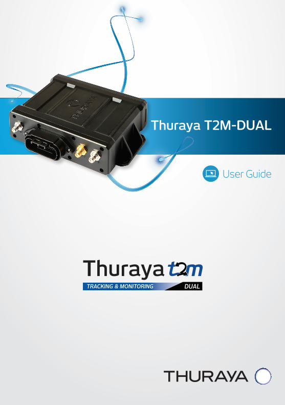
1 INTRODUCTION................................. 3 1.1 Overview ................................................ 3 1.2 T2M-DUAL System Diagram...... 3
2 GETTING STARTED ......................... 4 2.1 In the Box ............................................... 4 2.2 Connection Diagram ....................... 5 2.3 Features ................................................. 5
3 HARDWARE ........................................ 6 3.1 T2M-DUAL (Thuraya Tracking and
Monitoring) ............................................ 6 3.2 SAT & GPS Antenna ........................ 10 3.3 I/O Cable Assembly ......................... 11 3.4 3G Antenna .......................................... 13 3.5 Back-Up Battery ............................... 13 3.6 Antenna Cables ................................. 14
4 FUNCTIONAL DESCRIPTION .14 4.1 Communication Mode .................... 14 4.2 Track mode and GPIO mode ...... 15 4.3 Data Logger ......................................... 15 4.4 Necessary and Selectable Data .......................................................... 15 4.5 Data Sampling Interval
(For periodic data) ........................... 17 4.6 Event Data (Non-Periodic Data) ......................... 17 4.7 GPIO Port ............................................... 18 4.8 Over Speed Alarm Setting........... 18 4.9 Shock Limit Setting ......................... 18 4.10 Speed, RPM and Brake
Coefficient Setting ........................... 18 4.11 J1939 CAN Data................................. 19 4.12 Driving Report .................................... 20 4.13 Geo-Fence ............................................ 20
5 I/O PORTS DESCRIPTION ............ 21 5.1 GPIO Port ............................................... 21 5.1.1 Digital Input .......................................... 21 5.1.2 Digital Output ..................................... 22 5.1.3 Analog Input ......................................... 23 5.2 Serial Interfaces .............................. 23
6 INSTALLATION ................................. 24 6.1 Prepare for the installation ....... 24 6.2 Select the proper mounting
locations ............................................... 25 6.2.1 Antenna Location ............................. 25 6.2.2 Terminal location .............................. 26 6.3 Mounting the antenna ................... 26 6.3.1 Magnet mounting ............................. 26 6.3.2 Screw mounting using bracket . 26 6.4 Mounting the terminal ................... 27 6.5 Routing the SAT & GPS antenna cables ........................ 29 6.6 Connecting the 26 pin I/O cable ......................................................... 29 6.7 Terminal power up and operation. ..................................................................... 29
7 SPECIFICATIONS .............................. 30 7.1 General specifications ................... 30 7.2 Terminal specifications ................. 30 7.3 Antenna specifications ................. 31 7.4 Accessories .......................................... 31
8 LIMITED WARRANTY ...................... 32 LIMITED WARRANTY ................................... 32
CONTENTS
1
Thuraya T2M-DUAL
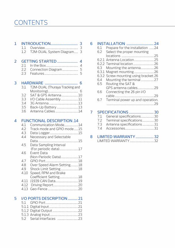
TABLES
TABLE 1 TERMINAL ANTENNA INTERFACES ............................................................................................. 6TABLE 2 TERMINAL REAR SIDE INTERFACE ............................................................................................... 7TABLE 3 LED FUNCTIONS ...................................................................................................................................... 8TABLE 4 DIP SWITCH FUNCTIONS .................................................................................................................... 9TABLE 5 SAT&GPS ANTENNA .............................................................................................................................. 10TABLE 6 CONNECTOR PIN DESCRIPTION .................................................................................................... 12TABLE 7 ANTENNA CABLES ................................................................................................................................. 14TABLE 8 COMMUNICATION MODES ................................................................................................................ 14TABLE 9 TRACK & GPIO MODES ........................................................................................................................ 15TABLE 10 NECESSARY & SELECTABLE DATA ............................................................................................... 16TABLE 11 PERIODIC DATA ......................................................................................................................................... 17TABLE 12 EVENT DATA ............................................................................................................................................... 17TABLE 13 I/O PORT ....................................................................................................................................................... 18TABLE 14 ANALOG COEFFICIENT ........................................................................................................................ 19TABLE 15 J1939 CAN DATA ....................................................................................................................................... 19TABLE 16 GENERAL SPECIFICATIONS .............................................................................................................. 30TABLE 17 TERMINAL SPECIFICATIONS ............................................................................................................ 30TABLE 18 ANTENNA SPECIFICATIONS ............................................................................................................. 31TABLE 19 ACCESSORY SPECIFICAITONS ........................................................................................................ 31
FIGURES
FIGURE 1 T2M-DUAL SYSTEM DIAGRAM ....................................................................................................... 3FIGURE 2 BOX CONTENTS ..................................................................................................................................... 4FIGURE 3 T2M-DUAL CONNECTION DIAGRAM .......................................................................................... 5FIGURE 4 T2M-DUAL TERMINAL FRONT SIDE ............................................................................................ 6FIGURE 5 T2M-DUAL 1 TERMINAL REAR SIDE ........................................................................................... 7FIGURE 6 LEDS ................................................................................................................................................................ 8FIGURE 7 DIP SWITCH ................................................................................................................................................. 9FIGURE 8 SAT & GPS ANTENNA ........................................................................................................................... 10FIGURE 9 26 PIN I/O CABLES ASSEMBLY ....................................................................................................... 11FIGURE 10 CABLE ASSEMBLY DRAWING .......................................................................................................... 11FIGURE 11 CONNECTOR PIN ALLOCATION...................................................................................................... 12FIGURE 12 3G EXTERANL ANTENNA ................................................................................................................... 13FIGURE 13 BACK-UP BATTERY ................................................................................................................................. 13FIGURE 14 DIGITAL INPUT ........................................................................................................................................... 21FIGURE 15 DIGITAL OUTPUT ..................................................................................................................................... 22FIGURE 16 ANALOG INPUT ......................................................................................................................................... 23FIGURE 17 ANTENNA MOUNTING LOCATION ................................................................................................ 25FIGURE 18 ANTENNA BRACKET FIXING ............................................................................................................. 26FIGURE 19 ANTENNA FIXING .................................................................................................................................... 26FIGURE 20 SIM, BATTERY, DIP SIWTCH ............................................................................................................... 27FIGURE 21 DIP SWITCH POSITION ......................................................................................................................... 27FIGURE 22 INSTALLING THE REAR COVER ..................................................................................................... 28FIGURE 23 TERMINAL MOUNTING ........................................................................................................................ 28
2
Thuraya T2M-DUAL
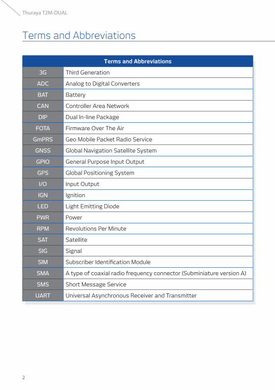
Terms and Abbreviations
3G Third Generation
ADC Analog to Digital Converters
BAT Battery
CAN Controller Area Network
DIP Dual In-line Package
FOTA Firmware Over The Air
GmPRS Geo Mobile Packet Radio Service
GNSS Global Navigation Satellite System
GPIO General Purpose Input Output
GPS Global Positioning System
I/O Input Output
IGN Ignition
LED Light Emitting Diode
PWR Power
RPM Revolutions Per Minute
SAT Satellite
SIG Signal
SIM Subscriber Identification Module
SMA A type of coaxial radio frequency connector (Subminiature version A)
SMS Short Message Service
UART Universal Asynchronous Receiver and Transmitter
Terms and Abbreviations
3
Thuraya T2M-DUAL
1.1 OVERVIEW
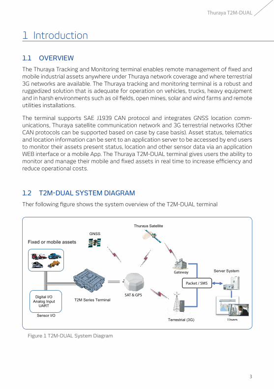
The Thuraya Tracking and Monitoring terminal enables remote management of fixed and mobile industrial assets anywhere under Thuraya network coverage and where terrestrial 3G networks are available. The Thuraya tracking and monitoring terminal is a robust and ruggedized solution that is adequate for operation on vehicles, trucks, heavy equipment and in harsh environments such as oil fields, open mines, solar and wind farms and remote utilities installations.
The terminal supports SAE J1939 CAN protocol and integrates GNSS location comm-unications, Thuraya satellite communication network and 3G terrestrial networks (Other CAN protocols can be supported based on case by case basis). Asset status, telematics and location information can be sent to an application server to be accessed by end users to monitor their assets present status, location and other sensor data via an application WEB interface or a mobile App. The Thuraya T2M-DUAL terminal gives users the ability to monitor and manage their mobile and fixed assets in real time to increase efficiency and reduce operational costs.
1.2 T2M-DUAL SYSTEM DIAGRAM
Ther following figure shows the system overview of the T2M-DUAL terminal
Figure 1 T2M-DUAL System Diagram
Gateway
SAT & GPS
Packet / SMS
1 Introduction
4
Thuraya T2M-DUAL
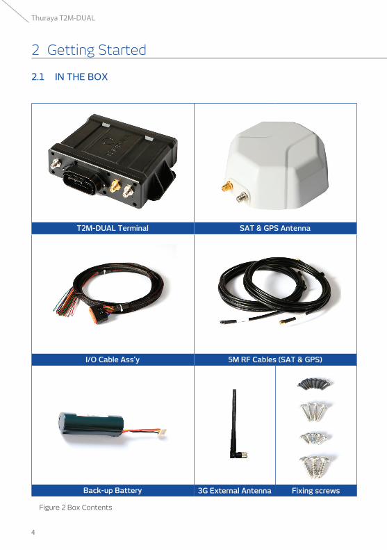
Back-up Battery 3G External Antenna Fixing screws
I/O Cable Ass’y 5M RF Cables (SAT & GPS)
T2M-DUAL Terminal SAT & GPS Antenna
Figure 2 Box Contents
2 Getting Started
2.1 IN THE BOX
5
Thuraya T2M-DUAL
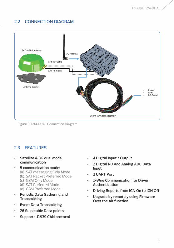
2 Getting Started 2.2 CONNECTION DIAGRAM
Figure 3 T2M-DUAL Connection Diagram
2.3 FEATURES
• Satellite & 3G dual mode communication
• 5 communication mode: (a) SAT messaging Only Mode (b) SAT Packet Preferred Mode (c) GSM Only Mode (d) SAT Preferred Mode (e) GSM Preferred Mode
• Periodic Data Gathering and Transmitting
• Event Data Transmitting
• 26 Selectable Data points
• Supports J1939 CAN protocol
• 4 Digital Input / Output
• 2 Digital I/O and Analog ADC Data Input
• 2 UART Port
• 1-Wire Communication for Driver Authentication
• Driving Reports from IGN On to IGN Off
• Upgrade by remotely using Firmware Over the Air function.
GPS RF Cable
SAT RF Cable
Power CAN I/O Signal
SAT & GPS Antenna
Antenna Bracket
3G Antenna
26 Pin I/O Cable Assembly
6
Thuraya T2M-DUAL
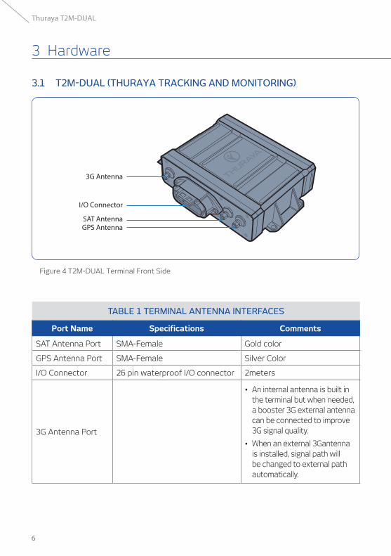
3.1 T2M-DUAL (THURAYA TRACKING AND MONITORING)
Figure 4 T2M-DUAL Terminal Front Side
TABLE 1 TERMINAL ANTENNA INTERFACES
Port Name Specifications Comments
SAT Antenna Port SMA-Female Gold color
GPS Antenna Port SMA-Female Silver Color
I/O Connector 26 pin waterproof I/O connector 2meters
3G Antenna Port
• An internal antenna is built in the terminal but when needed, a booster 3G external antenna can be connected to improve 3G signal quality.
• When an external 3Gantenna is installed, signal path will be changed to external path automatically.
3 Hardware
3G Antenna
I/O Connector
SAT AntennaGPS Antenna
7
Thuraya T2M-DUAL
3 Hardware
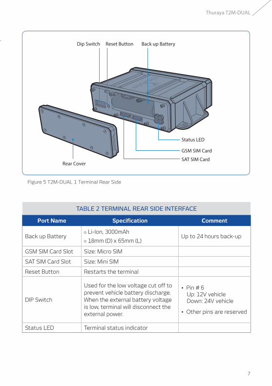
Figure 5 T2M-DUAL 1 Terminal Rear Side
TABLE 2 TERMINAL REAR SIDE INTERFACE
Port Name Specification Comment
Back up Battery Li-Ion, 3000mAh
18mm (D) x 65mm (L)Up to 24 hours back-up
GSM SIM Card Slot Size: Micro SIM
SAT SIM Card Slot Size: Mini SIM
Reset Button Restarts the terminal
DIP Switch
Used for the low voltage cut off to prevent vehicle battery discharge. When the external battery voltage is low, terminal will disconnect the external power.
• Pin # 6 Up: 12V vehicle Down: 24V vehicle
• Other pins are reserved
Status LED Terminal status indicator
Back up Battery
Status LED
GSM SIM Card
SAT SIM CardRear Cover
Reset ButtonDip Switch
8
Thuraya T2M-DUAL
PWRSAT
GSMGPS
ON1 2 3 4 5 6
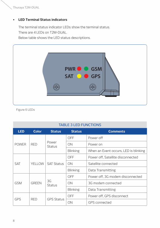
• LED Terminal Status indicators
The terminal status indicator LEDs show the terminal status.
There are 4 LEDs on T2M-DUAL.
Below table shows the LED status descriptions.
Figure 6 LEDs
TABLE 3 LED FUNCTIONS
LED Color Status Status Comments
POWER REDPower Status
OFF Power off
ON Power on
Blinking When an Event occurs, LED is blinking
SAT YELLOW SAT Status
OFF Power off, Satellite disconnected
ON Satellite connected
Blinking Data Transmitting
GSM GREEN3G Status
OFF Power off, 3G modem disconnected
ON 3G modem connected
Blinking Data Transmitting
GPS RED GPS StatusOFF Power off, GPS disconnect
ON GPS connected
9
Thuraya T2M-DUAL
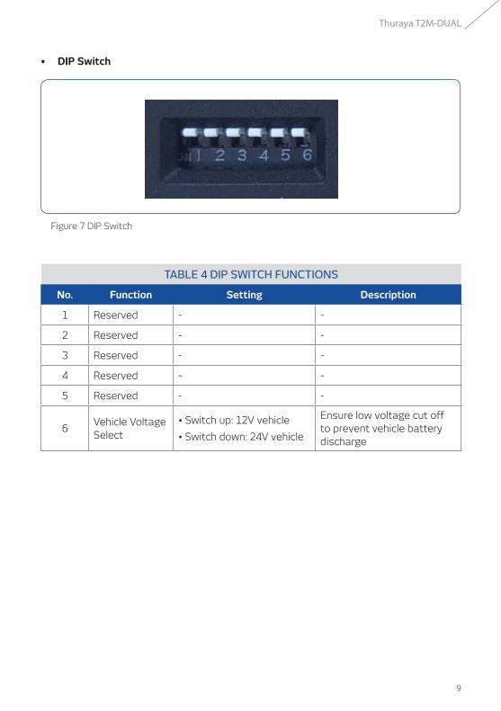
• DIP Switch
Figure 7 DIP Switch
TABLE 4 DIP SWITCH FUNCTIONS
No. Function Setting Description
1 Reserved - -
2 Reserved - -
3 Reserved - -
4 Reserved - -
5 Reserved - -
6Vehicle Voltage Select
• Switch up: 12V vehicle
• Switch down: 24V vehicle
Ensure low voltage cut off to prevent vehicle battery discharge
10
Thuraya T2M-DUAL
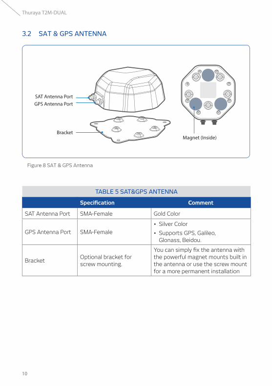
3.2 SAT & GPS ANTENNA
Figure 8 SAT & GPS Antenna
TABLE 5 SAT&GPS ANTENNA
Specification Comment
SAT Antenna Port SMA-Female Gold Color
GPS Antenna Port SMA-Female
• Silver Color
• Supports GPS, Galileo, Glonass, Beidou.
BracketOptional bracket for screw mounting.
You can simply fix the antenna with the powerful magnet mounts built in the antenna or use the screw mount for a more permanent installation
BracketMagnet (Inside)
GPS Antenna PortSAT Antenna Port
11
Thuraya T2M-DUAL
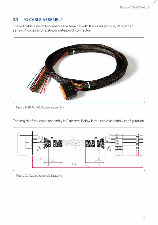
3.3 I/O CABLE ASSEMBLY
The I/O cable assembly connects the terminal with the asset (vehicle, RTU, etc.) or sensor. It consists of a 26-pin waterproof connector.
Figure 9 26 Pin I/O Cables Assembly
The length of the cable assembly is 2 meters. Below is the cable assembly configuration
Figure 10 Cable Assembly Drawing
12
Thuraya T2M-DUAL
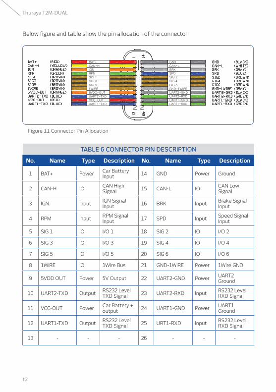
Below figure and table show the pin allocation of the connector
Figure 11 Connector Pin Allocation
TABLE 6 CONNECTOR PIN DESCRIPTION
No. Name Type Description No. Name Type Description
1 BAT+ Power Car Battery Input 14 GND Power Ground
2 CAN-H IO CAN High Signal 15 CAN-L IO CAN Low
Signal
3 IGN Input IGN Signal Input 16 BRK Input Brake Signal
Input
4 RPM Input RPM Signal Input 17 SPD Input Speed Signal
Input
5 SIG 1 IO I/O 1 18 SIG 2 IO I/O 2
6 SIG 3 IO I/O 3 19 SIG 4 IO I/O 4
7 SIG 5 IO I/O 5 20 SIG 6 IO I/O 6
8 1WIRE IO 1Wire Bus 21 GND-1WIRE Power 1Wire GND
9 5VDD OUT Power 5V Output 22 UART2-GND Power UART2 Ground
10 UART2-TXD Output RS232 Level TXD Signal 23 UART2-RXD Input RS232 Level
RXD Signal
11 VCC-OUT Power Car Battery + output 24 UART1-GND Power UART1
Ground
12 UART1-TXD Output RS232 Level TXD Signal 25 URT1-RXD Input RS232 Level
RXD Signal
13 - - - 26 - - -
13
Thuraya T2M-DUAL
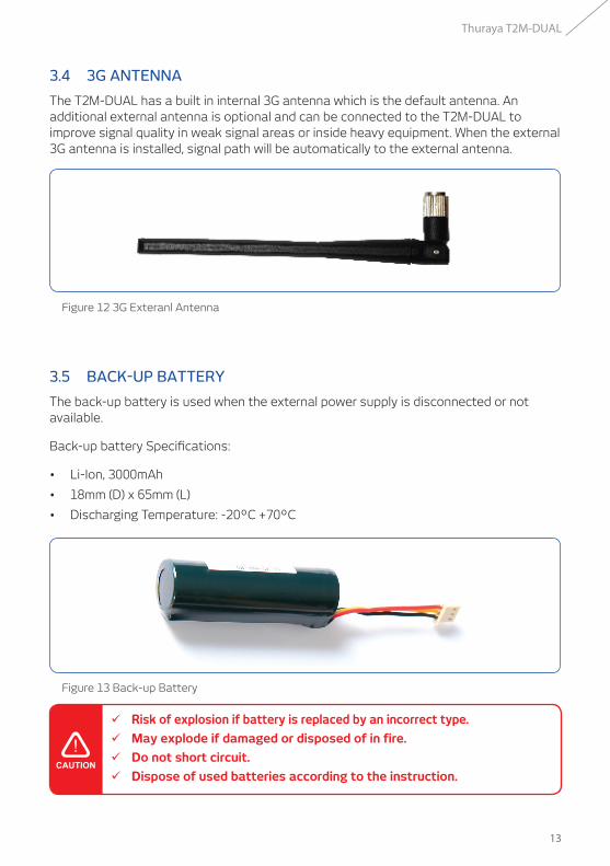
3.4 3G ANTENNA
The T2M-DUAL has a built in internal 3G antenna which is the default antenna. An additional external antenna is optional and can be connected to the T2M-DUAL to improve signal quality in weak signal areas or inside heavy equipment. When the external 3G antenna is installed, signal path will be automatically to the external antenna.
Figure 12 3G Exteranl Antenna
Figure 13 Back-up Battery
3.5 BACK-UP BATTERY
The back-up battery is used when the external power supply is disconnected or not available.
Back-up battery Specifications:
• Li-Ion, 3000mAh
• 18mm (D) x 65mm (L)
• Discharging Temperature: -20ºC +70ºC
ü Risk of explosion if battery is replaced by an incorrect type.
ü May explode if damaged or disposed of in fire.
ü Do not short circuit.
ü Dispose of used batteries according to the instruction.
14
Thuraya T2M-DUAL
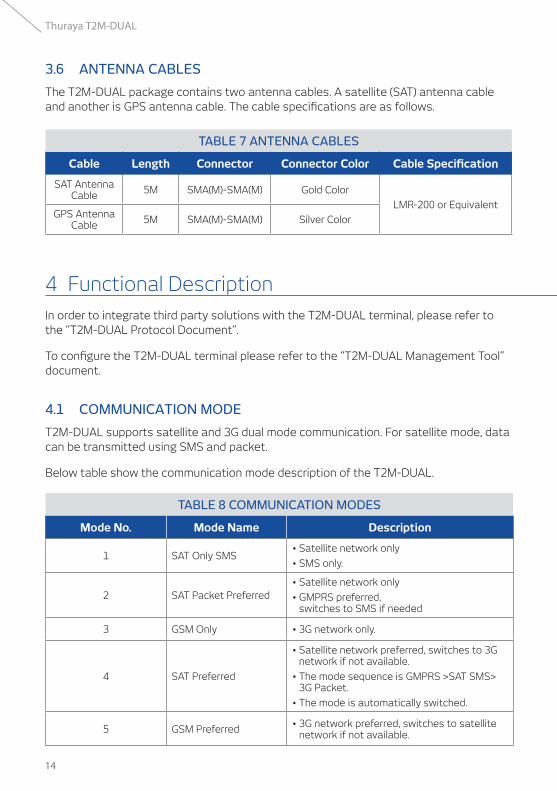
3.6 ANTENNA CABLES
The T2M-DUAL package contains two antenna cables. A satellite (SAT) antenna cable and another is GPS antenna cable. The cable specifications are as follows.
TABLE 7 ANTENNA CABLES
Cable Length Connector Connector Color Cable Specification
SAT Antenna Cable 5M SMA(M)-SMA(M) Gold Color
LMR-200 or EquivalentGPS Antenna
Cable 5M SMA(M)-SMA(M) Silver Color
In order to integrate third party solutions with the T2M-DUAL terminal, please refer to the “T2M-DUAL Protocol Document”.
To configure the T2M-DUAL terminal please refer to the “T2M-DUAL Management Tool” document.
4.1 COMMUNICATION MODE
T2M-DUAL supports satellite and 3G dual mode communication. For satellite mode, data can be transmitted using SMS and packet.
Below table show the communication mode description of the T2M-DUAL.
TABLE 8 COMMUNICATION MODES
Mode No. Mode Name Description
1 SAT Only SMS• Satellite network only
• SMS only.
2 SAT Packet Preferred• Satellite network only
• GMPRS preferred, switches to SMS if needed
3 GSM Only • 3G network only.
4 SAT Preferred
• Satellite network preferred, switches to 3G network if not available.
• The mode sequence is GMPRS >SAT SMS> 3G Packet.
• The mode is automatically switched.
5 GSM Preferred • 3G network preferred, switches to satellite network if not available.
4 Functional Description
15
Thuraya T2M-DUAL
4 Functional Description
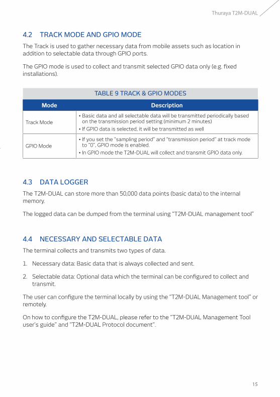
4.2 TRACK MODE AND GPIO MODE
The Track is used to gather necessary data from mobile assets such as location in addition to selectable data through GPIO ports.
The GPIO mode is used to collect and transmit selected GPIO data only (e.g. fixed installations).
TABLE 9 TRACK & GPIO MODES
Mode Description
Track Mode• Basic data and all selectable data will be transmitted periodically based
on the transmission period setting (minimum 2 minutes)
• If GPIO data is selected, it will be transmitted as well
GPIO Mode• If you set the “sampling period” and “transmission period” at track mode
to “0”, GPIO mode is enabled.
• In GPIO mode the T2M-DUAL will collect and transmit GPIO data only.
4.3 DATA LOGGER
The T2M-DUAL can store more than 50,000 data points (basic data) to the internal memory.
The logged data can be dumped from the terminal using “T2M-DUAL management tool”
4.4 NECESSARY AND SELECTABLE DATA
The terminal collects and transmits two types of data.
1. Necessary data: Basic data that is always collected and sent.
2. Selectable data: Optional data which the terminal can be configured to collect and transmit.
The user can configure the terminal locally by using the “T2M-DUAL Management tool” or remotely.
On how to configure the T2M-DUAL, please refer to the “T2M-DUAL Management Tool user’s guide” and “T2M-DUAL Protocol document”.

16
Thuraya T2M-DUAL
The table below details the necessary data and all selectable data.
TABLE 10 NECESSARY & SELECTABLE DATA
No Collection DataCollection
MethodNecessary Selective Comment
1 Time GPS V
• Default Data
2 Longitude GPS V
3 Latitude GPS V
4 Angle GPS V
5 IGN GPS V
6 Wheel Based Speed CAN / Sensor V
7 RPM (Engine Speed) CAN / Sensor V
8 Altitude (B1) GPS V
9 GPS Speed (B2) GPS V
10 Moving Distance (B3) Terminal V
11 Vehicle Battery Voltage (B4) Sensor V
12 G-Sensor (Shock) (B5) Sensor V
13 Internal Battery Voltage (A1) Sensor V
14 Terminal Temperature (A2) Sensor V
15 1-Wire (A3) Sensor V • Driver Authentication
16 Fuel Level (C1) CAN V
• These data from CAN are depends on the vehicle manufacturer and year.
• Support J-1939 protocol
17 Engine Hours (C2) CAN V
18 High Resolution total vehicle distance (C3) CAN V
19 Engine Coolant temparature (C4) CAN V
20 Ambient Temperature (C5) CAN V
21 Instantaneous Fuel Economy (C6) CAN V
22 Fuel Rate (C7) CAN V
23 Accelarator Pedal Position (C8) CAN V
24 Current Gear (C9) CAN V
26 IO 1 Digital V
27 IO 2 Digital V
28 IO 3 Digital V
29 IO 4 Digital V
30 IO 5 (ADC) Analog/Digital V
31 IO 6 (ADC) Analog/Digital V
32 UART 1 Data V
33 UART 2 Data V Ex) Thermometer
17
Thuraya T2M-DUAL
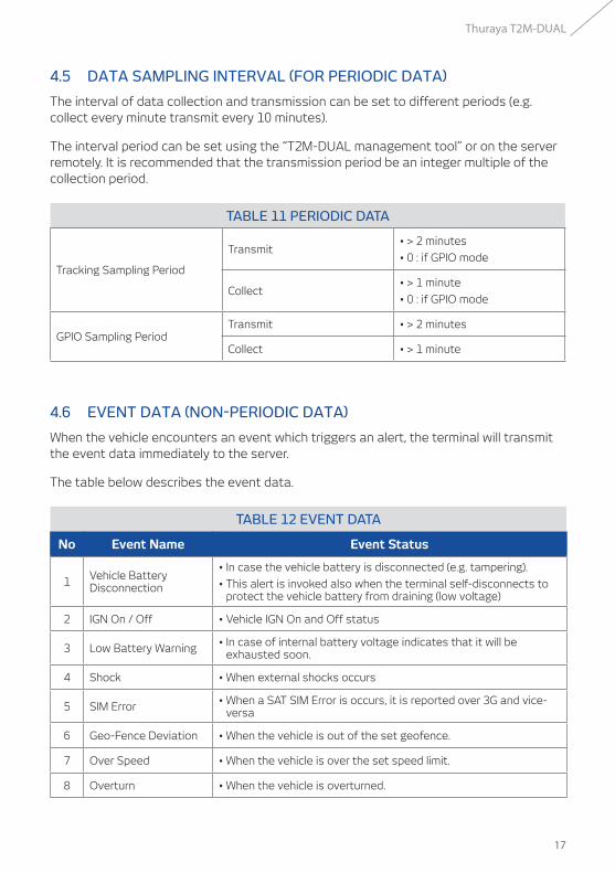
4.5 DATA SAMPLING INTERVAL (FOR PERIODIC DATA)
The interval of data collection and transmission can be set to different periods (e.g. collect every minute transmit every 10 minutes).
The interval period can be set using the “T2M-DUAL management tool” or on the server remotely. It is recommended that the transmission period be an integer multiple of the collection period.
TABLE 11 PERIODIC DATA
Tracking Sampling Period
Transmit• > 2 minutes
• 0 : if GPIO mode
Collect• > 1 minute
• 0 : if GPIO mode
GPIO Sampling PeriodTransmit • > 2 minutes
Collect • > 1 minute
4.6 EVENT DATA (NON-PERIODIC DATA)
When the vehicle encounters an event which triggers an alert, the terminal will transmit the event data immediately to the server.
The table below describes the event data.
TABLE 12 EVENT DATA
No Event Name Event Status
1 Vehicle Battery Disconnection
• In case the vehicle battery is disconnected (e.g. tampering).
• This alert is invoked also when the terminal self-disconnects to protect the vehicle battery from draining (low voltage)
2 IGN On / Off • Vehicle IGN On and Off status
3 Low Battery Warning • In case of internal battery voltage indicates that it will be exhausted soon.
4 Shock • When external shocks occurs
5 SIM Error • When a SAT SIM Error is occurs, it is reported over 3G and vice-versa
6 Geo-Fence Deviation • When the vehicle is out of the set geofence.
7 Over Speed • When the vehicle is over the set speed limit.
8 Overturn • When the vehicle is overturned.
18
Thuraya T2M-DUAL
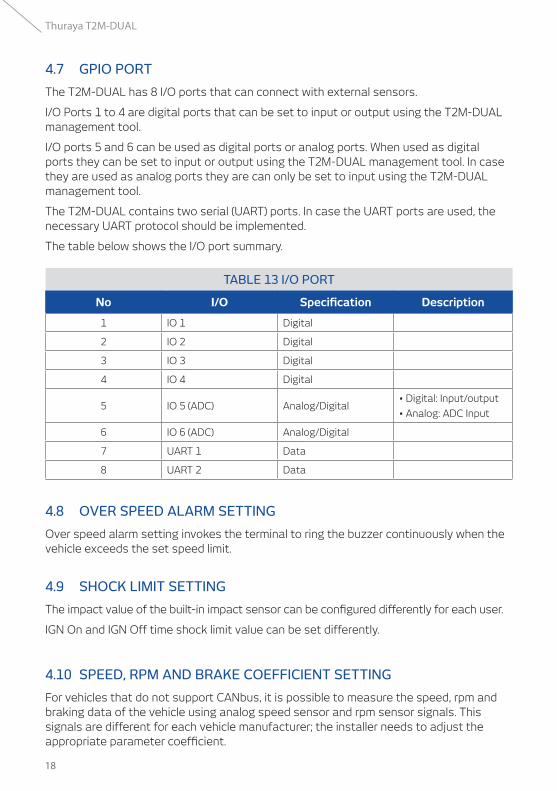
4.7 GPIO PORT
The T2M-DUAL has 8 I/O ports that can connect with external sensors.
I/O Ports 1 to 4 are digital ports that can be set to input or output using the T2M-DUAL management tool.
I/O ports 5 and 6 can be used as digital ports or analog ports. When used as digital ports they can be set to input or output using the T2M-DUAL management tool. In case they are used as analog ports they are can only be set to input using the T2M-DUAL management tool.
The T2M-DUAL contains two serial (UART) ports. In case the UART ports are used, the necessary UART protocol should be implemented.
The table below shows the I/O port summary.
TABLE 13 I/O PORT
No I/O Specification Description
1 IO 1 Digital
2 IO 2 Digital
3 IO 3 Digital
4 IO 4 Digital
5 IO 5 (ADC) Analog/Digital• Digital: Input/output
• Analog: ADC Input
6 IO 6 (ADC) Analog/Digital
7 UART 1 Data
8 UART 2 Data
4.8 OVER SPEED ALARM SETTING
Over speed alarm setting invokes the terminal to ring the buzzer continuously when the vehicle exceeds the set speed limit.
4.9 SHOCK LIMIT SETTING
The impact value of the built-in impact sensor can be configured differently for each user.
IGN On and IGN Off time shock limit value can be set differently.
4.10 SPEED, RPM AND BRAKE COEFFICIENT SETTING
For vehicles that do not support CANbus, it is possible to measure the speed, rpm and braking data of the vehicle using analog speed sensor and rpm sensor signals. This signals are different for each vehicle manufacturer; the installer needs to adjust the appropriate parameter coefficient.
19
Thuraya T2M-DUAL
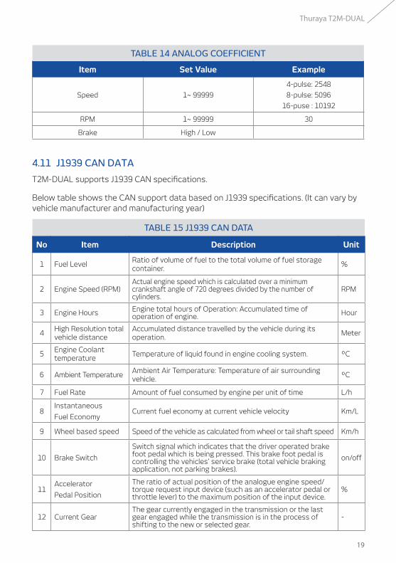
TABLE 14 ANALOG COEFFICIENT
Item Set Value Example
Speed 1~ 99999
4-pulse: 2548
8-pulse: 5096
16-puse : 10192
RPM 1~ 99999 30
Brake High / Low
4.11 J1939 CAN DATA
T2M-DUAL supports J1939 CAN specifications.
Below table shows the CAN support data based on J1939 specifications. (It can vary by vehicle manufacturer and manufacturing year)
TABLE 15 J1939 CAN DATA
No Item Description Unit
1 Fuel LevelRatio of volume of fuel to the total volume of fuel storage container.
%
2 Engine Speed (RPM)Actual engine speed which is calculated over a minimum crankshaft angle of 720 degrees divided by the number of cylinders.
RPM
3 Engine Hours Engine total hours of Operation: Accumulated time of operation of engine. Hour
4High Resolution total vehicle distance
Accumulated distance travelled by the vehicle during its operation.
Meter
5Engine Coolant temperature
Temperature of liquid found in engine cooling system. ºC
6 Ambient TemperatureAmbient Air Temperature: Temperature of air surrounding vehicle.
ºC
7 Fuel Rate Amount of fuel consumed by engine per unit of time L/h
8Instantaneous
Fuel EconomyCurrent fuel economy at current vehicle velocity Km/L
9 Wheel based speed Speed of the vehicle as calculated from wheel or tail shaft speed Km/h
10 Brake Switch
Switch signal which indicates that the driver operated brake foot pedal which is being pressed. This brake foot pedal is controlling the vehicles’ service brake (total vehicle braking application, not parking brakes).
on/off
11Accelerator
Pedal Position
The ratio of actual position of the analogue engine speed/torque request input device (such as an accelerator pedal or throttle lever) to the maximum position of the input device.
%
12 Current GearThe gear currently engaged in the transmission or the last gear engaged while the transmission is in the process of shifting to the new or selected gear.
-
20
Thuraya T2M-DUAL
4.12 DRIVING REPORT
If you turn off the vehicle key, a driving report will be generated and sent to the back-end application server. The driving report is part of the selectable data.
The followings data points are included in the driving report:
• IGN On time
• IGN Off time
• Driver’s name
• Driving distance (in meters)
• Number of brakes
• Number of harsh brakes
• Number of harsh accelerations
• Maximum speed during the driving
• Maximum RPM during the driving
4.13 GEO-FENCE
Geo-fences can be generated on the server and transferred to the terminal. If terminal receives the geo-fence data from the server, the terminal will store the data in the internal memory. If the vehicle is outside the geo-fence, the terminal beeps and sends an alert/ event to the back-end application server. Geo-fences can be set by packet mode only.
The T2M-DUAL terminal supports up to 128 geo-fencing polygons of geo-fence. A polygon can be defined by up to 64 points.
21
Thuraya T2M-DUAL
5.1 GPIO PORT
The terminal’s 6 configurable GPIO lines are each independently operable in one of following modes:
• Digital Input
• Digital Output
• Analog Input (I/O# 5, 6)
• Disabled.
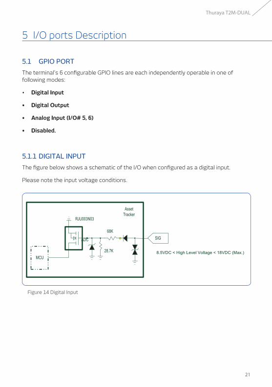
5.1.1 DIGITAL INPUT
The figure below shows a schematic of the I/O when configured as a digital input.
Please note the input voltage conditions.
Figure 14 Digital Input
5 I/O ports Description

22
Thuraya T2M-DUAL
5.1.2 DIGITAL OUTPUT
The figure below shows a schematic of the I/O when configured as digital output.
Please note the voltage and current curves.
Figure 15 Digital Output
23
Thuraya T2M-DUAL
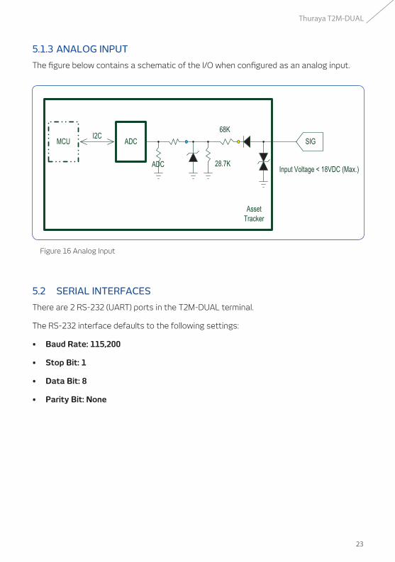
5.1.3 ANALOG INPUT
The figure below contains a schematic of the I/O when configured as an analog input.
Figure 16 Analog Input
5.2 SERIAL INTERFACES
There are 2 RS-232 (UART) ports in the T2M-DUAL terminal.
The RS-232 interface defaults to the following settings:
• Baud Rate: 115,200
• Stop Bit: 1
• Data Bit: 8
• Parity Bit: None
24
Thuraya T2M-DUAL
This section outlines the standard installation guidelines for the installers. During the installation, the installer should take all the necessary safety precautions. The installer should take every precaution in order not to damage the vehicle during the installation procedure. The general installation procedure is as follows.
1. Prepare for the installation.
2. Select proper locations for antenna and terminal.
3. Mount the antenna.
4. Mount the terminal
5. Rout the SAT & GPS antenna cable
6. Connect the 26pin I/O cable
7. Key on and operating.
6.1 PREPARE FOR THE INSTALLATION
Before installation, the installer should prepare the following:
1. Prepare the necessary tools and auxiliary materials for required for mounting the hardware
2. Set the terminal using “T2M-DUAL Management Tool” for communication mode, selectable data, server IP, short code and any other necessary configurations.
3. Insert the SIM cards and back up battery into the terminal and set the vehicle voltage DIP switch.
4. Affix the back cover and fasten the screws.
6 Installation
ü The installation must be done by a skilled installation professional.
ü The installer must comply with all safety precautions and not to damage the vehicle.
ü Before the start of the installation of the terminal, Set the terminal parameters using the “T2M-DUAL Management Tool”.
25
Thuraya T2M-DUAL
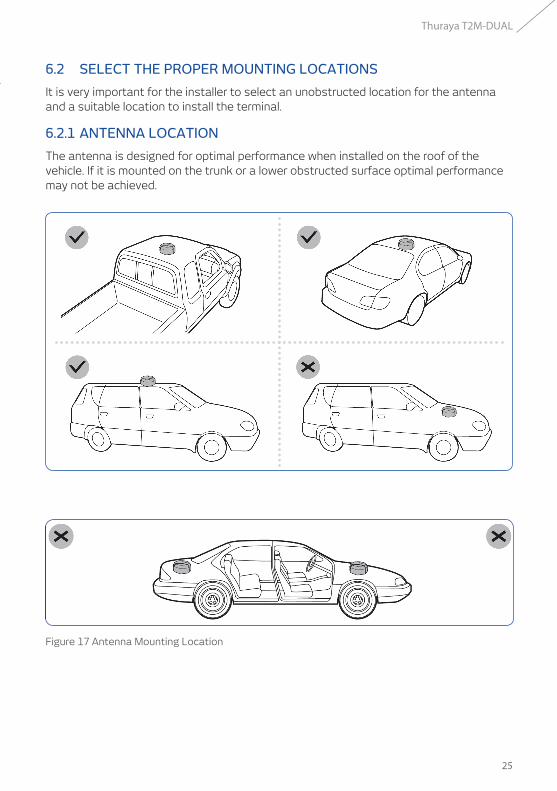
6 Installation 6.2 SELECT THE PROPER MOUNTING LOCATIONS
It is very important for the installer to select an unobstructed location for the antenna and a suitable location to install the terminal.
6.2.1 ANTENNA LOCATION
The antenna is designed for optimal performance when installed on the roof of the vehicle. If it is mounted on the trunk or a lower obstructed surface optimal performance may not be achieved.
Figure 17 Antenna Mounting Location
26
Thuraya T2M-DUAL
6.2.2 TERMINAL LOCATION
Some suggested locations to install the T2M-DUAL terminal are under the passenger seat or under the dashboard. When mounting the T2M-DUAL, it is important to keep the terminal as horizontal as possible.
6.3 MOUNTING THE ANTENNA
The antenna should be fixed after selecting the proper mounting position. There are two methods to fix the antenna. Either by simply fixing it on the top of the vehicle using the magnet mounts or the screw mounting bracket for a more permanent installation.
6.3.1 MAGNET MOUNTING
There are 4 magnets in the inside of the antenna bottom. Therefore, it can be mounted on conductive (metal) surface on the roof of the vehicle. It will withstand very high velocity of the vehicle. Before mounting, remove and clean the dust on the surface to be installed. And put the antenna there.
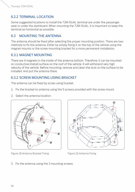
6.3.2 SCREW MOUNTING USING BRACKET
The antenna can be fixed by screw using bracket.
1. Fix the bracket to antenna using the 5 screws provided with the screw mount.
2. Select the antenna location.
Figure 18 Antenna Bracket Fixing Figure 19 Antenna Fixing
3. Fix the antenna using the 3 mounting screws.
27
Thuraya T2M-DUAL
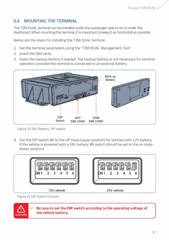
6.4 MOUNTING THE TERMINAL
The T2M-DUAL terminal can be installed under the passenger seat or on or under the dashboard. When mounting the terminal, it is important to keep it as horizontal as possible.
Below are the steps for installing the T2M-DUAL terminal.
1. Set the terminal parameters using the “T2M-DUAL Management Tool”
2. Insert the SIM cards.
3. Insert the backup battery if needed. The backup battery is not necessary for terminal operation provided the terminal is connected to an external battery.
Figure 20 SIM, Battery, DIP siwtch
Figure 21 DIP Switch Position
4. Set the DIP switch #6 to the off state (upper position) for vehicles with 12V battery. If the vehicle is powered with a 24V battery, #6 switch should be set to the on state (lower position)
ü Be sure to set the DIP switch according to the operating voltage of the vehicle battery.
28
Thuraya T2M-DUAL
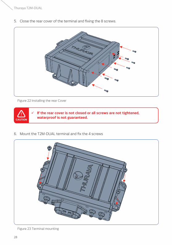
5. Close the rear cover of the terminal and fixing the 8 screws.
6. Mount the T2M-DUAL terminal and fix the 4 screws
Figure 22 Installing the rear Cover
Figure 23 Terminal mounting
ü If the rear cover is not closed or all screws are not tightened, waterproof is not guaranteed.
29
Thuraya T2M-DUAL
6.5 ROUTING THE SAT & GPS ANTENNA CABLES
Connect the 5M RF cables from the antenna to the terminal.
Route the RF cables so that the door or window closes properly and does not damage the cable. Be careful not to twist or break the cable and tighten the RF cable using cable tie.
6.6 CONNECTING THE 26 PIN I/O CABLE
Prior to working on any cabling, ensure that the terminal is powered off while work is in progress.
Connect the I/O connector to the terminal and also connect the opposite side of the cable to the vehicle and appropriate monitoring sensors and peripherals (Digital/ analog sensors, serial devices, I wire cable etc.).
The pins #1(BAT+), #14(GND), and #3(IGN) associated with the power supply must be connected. The remaining cables are connected to the various sensors as needed. Please refer to Table 6 for a detailed cable pin description.
6.7 TERMINAL POWER UP AND OPERATION.
After connecting the cable, plug the 26-pin connector into the terminal.
The terminal will be turned on automatically.
Data transmission will start and should be received at the server.
ü Be careful not to twist or break the antenna RF cables.
ü The pins #1(BAT+), #14(GND), and #3(IGN) associated with the power supply must be connected
ü Prior to working on any cabling, ensure that the terminal is powered off and unable to start while work is in progress.
30
Thuraya T2M-DUAL
7.1 GENERAL SPECIFICATIONS
7.2 TERMINAL SPECIFICATIONS
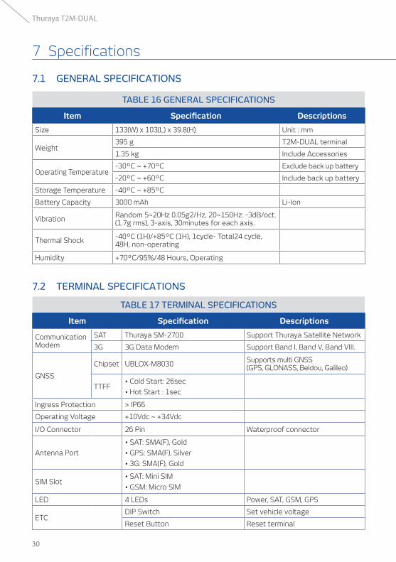
TABLE 16 GENERAL SPECIFICATIONS
Item Specification Descriptions
Size 133(W) x 103(L) x 39.8(H) Unit : mm
Weight395 g T2M-DUAL terminal
1.35 kg Include Accessories
Operating Temperature-30ºC ~ +70ºC Exclude back up battery
-20ºC ~ +60ºC Include back up battery
Storage Temperature -40ºC ~ +85ºC
Battery Capacity 3000 mAh Li-Ion
Vibration Random 5~20Hz 0.05g2/Hz, 20~150Hz: -3dB/oct.(1.7g rms), 3-axis, 30minutes for each axis.
Thermal Shock -40ºC (1H)/+85ºC (1H), 1cycle- Total24 cycle, 48H, non-operating
Humidity +70ºC/95%/48 Hours, Operating
TABLE 17 TERMINAL SPECIFICATIONS
Item Specification Descriptions
CommunicationModem
SAT Thuraya SM-2700 Support Thuraya Satellite Network
3G 3G Data Modem Support Band I, Band V, Band VIII.
GNSS
Chipset UBLOX-M8030 Supports multi GNSS (GPS, GLONASS, Beidou, Galileo)
TTFF• Cold Start: 26sec
• Hot Start : 1sec
Ingress Protection > IP66
Operating Voltage +10Vdc ~ +34Vdc
I/O Connector 26 Pin Waterproof connector
Antenna Port
• SAT: SMA(F), Gold
• GPS: SMA(F), Silver
• 3G: SMA(F), Gold
SIM Slot• SAT: Mini SIM
• GSM: Micro SIM
LED 4 LEDs Power, SAT, GSM, GPS
ETCDIP Switch Set vehicle voltage
Reset Button Reset terminal
7 Specifications
31
Thuraya T2M-DUAL
7 Specifications 7.3 ANTENNA SPECIFICATIONS
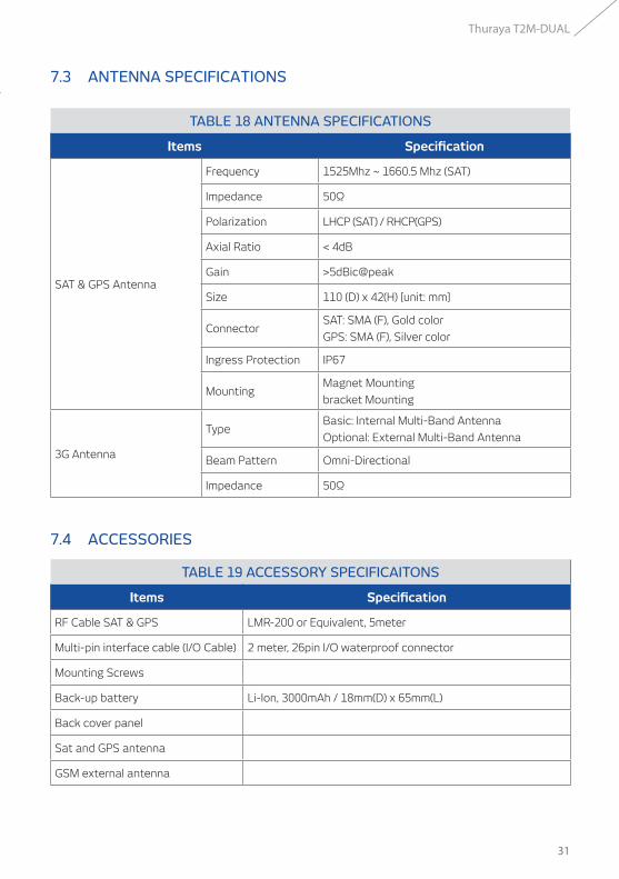
TABLE 18 ANTENNA SPECIFICATIONS
Items Specification
SAT & GPS Antenna
Frequency 1525Mhz ~ 1660.5 Mhz (SAT)
Impedance 50Ω
Polarization LHCP (SAT) / RHCP(GPS)
Axial Ratio < 4dB
Gain >5dBic@peak
Size 110 (D) x 42(H) [unit: mm]
ConnectorSAT: SMA (F), Gold color
GPS: SMA (F), Silver color
Ingress Protection IP67
MountingMagnet Mounting
bracket Mounting
3G Antenna
TypeBasic: Internal Multi-Band Antenna
Optional: External Multi-Band Antenna
Beam Pattern Omni-Directional
Impedance 50Ω
7.4 ACCESSORIES
TABLE 19 ACCESSORY SPECIFICAITONS
Items Specification
RF Cable SAT & GPS LMR-200 or Equivalent, 5meter
Multi-pin interface cable (I/O Cable) 2 meter, 26pin I/O waterproof connector
Mounting Screws
Back-up battery Li-Ion, 3000mAh / 18mm(D) x 65mm(L)
Back cover panel
Sat and GPS antenna
GSM external antenna
32
Thuraya T2M-DUAL
LIMITED WARRANTY
This Limited Warranty is provided to the original end-user purchaser (the ‘Buyer’) of any new Thuraya T2M-DUAL terminal. This Limited Warranty is non-transferable.
Warranty Coverage and Service
Thuraya warrants all new Thuraya T2M-DUAL terminals (the ‘Product’) under normal use and wear to be free from defects in material and workmanship for a period of one (1) year from the date of purchase by the original Buyer (the ‘Warranty Period’). If, under normal use and wear, the Product becomes defective in materials or workmanship and is returned at Buyer’s expense to a Thuraya Authorized Service Center during the Warranty Period, the Product will be repaired or replaced, at Thuraya’ sole and exclusive option, and at no charge to Buyer. Buyer will be required to provide reasonable proof of date of purchase.
Reconditioned replacement components, parts, units or materials may be used if the Product is repaired or replaced. Costs incurred in the removal, de-installation or reinstallation of the Product are not covered.
THIS LIMITED WARRANTY DOES NOT COVER AND THURAYA WILL NOT BE RESPONSIBLE FOR THE FOLLOWING:
This Limited Warranty will be void in its entirety if the Product is serviced by anyone other than Thuraya or a Thuraya Authorized Service Centre. Buyer’s sole and exclusive remedy shall be the repair or replacement of the defective product, as specifically described above. Thuraya neither assumes nor authorizes any Authorized Service Centre or any other person or entity to assume any other obligation or liability beyond that which is provided for in this Limited Warranty.
This Limited Warranty is conditioned upon proper use of the Product and does not cover the following:
• products or accessory equipment not manufactured or provided by Thuraya
• failures or defects caused by misuse, abuse, accident, alteration, dampness, sand, unusual physical, electrical or electromechanical stress or neglect
• unauthorized installation, removal or repair
• failure to follow instructions
• fire, flood or other nature caused accidents
• spills of food or liquids; moisture
8 Limited Warranty .....
8 Limited Warranty .....
• normal wear and tear
• scratches, dents and cosmetic damage
• improper installation, maintenance or improper storage
• operation or repair; performance of the Product when used in combination with other products or equipment not manufactured or provided by Thuraya
• payments for labor or service to representatives or service centers not authorized by Thuraya
This limited Warranty of the Product does not cover the operation, availability, coverage, range or grade of service provided by the satellite systems.